#help-with-arduino
1 messages · Page 82 of 1
 reef ravine
 silver tundra
Sorry to jump in here, but have a kinda random question and am not sure which channel this should go into. I know that the NeoPixel Matrix library can be used for scrolling text, but was curious if someone has a nice article that explains the math behind how that works?
reef ravine
and the current only flows when the transistor is on
@silver tundra either here or #help-with-projects
silver tundra
I am trying to scroll the text on an arduino and have my own function to "render" what I want on an 8x8 display, but just don't understand the scroll piece. I have everything I want to render as byte arrays, is the scroll just a shift with of the bits?
 hoary canopy
Sorry, I'm hogging the channel! Just one last thing, this whole deal is because we're dealing with different voltages? If the sensor was working on 5v, this wouldn't be necessary?
reef ravine
because I2C uses open drain, they are needed, regardless of voltage
 stuck coral
@silver tundra if you know the width of a row, then you can translate the coordinates from 2d space to a 1D array (WIDTH * row) + column (No translation for alternating rows)
hoary canopy
Alright thanks for your patience, I'll go digest that now 😛
reef ravine
happy hacking!
silver tundra
@stuck coral I have an 8x8 matrix, so for each letter I do 8 * 8 * character count?
So basically if I have 10 letters, each letter is 8 columns wide, then I would have a single array that is 80 characters long. Then run a for loop that moves through each 1D "pixel"?
stuck coral
No, so if you are drawing to a display buffer, and you have an X and Y coordinates for drawing the text, you can translate it to a 1D buffer-
buffer[( DISPLAY_WIDTH * x ) + y)] = value
IS your display RGB or RGBW or BRG?
silver tundra
GRB
stuck coral
Okay, one moment
#define WIDTH 8
#define HEIGHT 8
#define VALS 3

uint8_t frame_buffer[WIDTH*HEIGHT*VALS]; // create a 192 byte buffer for 64 GRB values

void draw(int x, int y, uint8_t R, uint8_t G, uint8_t B){
  framebuffer[(VALS * WIDTH * x) + y] = G;
  framebuffer[(VALS * WIDTH * x) + y + 1] = R;
  framebuffer[(VALS * WIDTH * x) + y + 2] = B;
}

void write(){
  function_to_write_to_neopixels(&frame_buffer, sizeof frame_buffer);
}
I thinkj I got that right, Im pretty tired
silver tundra
No worries, sorry I am a bit new so I'm trying to digest this. The VALs is 3 because we have each of the three colors to render?
stuck coral
Right
Not there is no bi-column translation here
There is a technical word for what I am thinking of but Im blanking
silver tundra
Sorry, I'm still trying to understand the code. I'm still learning so it's taking me a bit to wrap my brain around this. I don't think I understand vals still though, since we already have 3 frame buffers
stuck coral
I dont know what you already have, I am showing you an imlpementaion with one single frame buffer so that you dont need an extra buffer which just consumes memory for no reason
Because if you have three buffers each the total number of LEDs per color, then you need to make a final buffer three times that size to combine them before sending to the neopixels
Unless you bitbang, which you dont want to do
I think I got x and Y backwards
Or something else
silver tundra
Sorry, I'm reading online. I think I may be bitbanging right now in my project haha
Basically, I have a few byte arrays like this:
{B00011000,B00111100,B01111110,B11011011,B11111111,B00100100,B01011010,B10100101}
Each bit of the byte reflecting which LED to turn on. I then do a for loop for each row/column and then set the pixel if 1.
stuck coral
Ah, very different problem, so you dont want color?
And what do you need from this then?
silver tundra
Ah, so today I pass the color in along side with the byte array on the drawShape function I have.
Displaying the pixel and color I think I have working, I just don't understand the math to "scroll" my drawing
stuck coral
Ah got it, well I need to go soon and that is going to take more time than I have, maybe someone here can answer or Im sure google has many related results
silver tundra
no worries, I do appreciate the help.
 shell palm
Hello all, first time posting here. Would someone be able to suggest how to have a 3.3v microcontroller (Teensy or Pro Mini) control 5v X9C102 digital potentiometer? I've tried level converting but wiper doesn't move. The X9C102 works fine when used with my 5v microcontollers but I am upgarding a project and haven't been able get 5v digital potentiometer to play nice with 3v microcontroller.
hoary canopy
Wow. I just looked up details on what open drain is and all of this finally makes sense!
I assumed it worked like the top switch, but it works like the bottom one https://ferdz.needs-to-s.top/AVDH3oE.png

 north stream
@shell palm It ought to work fine, the input high threshold is 2 volts, so 3.3V logic should control it without needing level shifting. Make sure your power pins are hooked up appropriately for your signal levels, and everything shares a 0V reference.
reef ravine
@hoary canopy yes, the top one is more like a relay or SPDT switch (where 2 can connect to 1 or 3), a transistor switch is more like the the bottom one (where 1 is connected to 2 or it is not)
picture the gate or base as an electronic way of pushing the button. only a little force on the button can control a large current flow (not a perfect analogy but...)
hoary canopy
One thing I do not understand about the level shifting schematic is, shouldn't the gate be controlled by the signal? As I read it, it appears to be controlled by the 3.3V lane (which would always be high) https://ferdz.needs-to-s.top/6djHVvW.png
 reef ravine
now you get to details 🙂 a fet is controlled by the voltage between the gate and source
so if you hold the gate to a certain voltage and change the source voltage it's the same as moving the gate voltage
hoary canopy
My understanding of earlier would've let me to think of it like this 🤔 https://ferdz.needs-to-s.top/432CpL5.png

Actually that ground should've been on the lower side
reef ravine
thats very similar, just spin 90 deg and connect the resistor to Vcc
the devices on the other end can pull the pins low
hoary canopy
Ok hold on
reef ravine
both fets and bjts can be used as switches (and also as linear amplifiers), but internally they work on a different principle
hoary canopy
This looks more right? https://ferdz.needs-to-s.top/2bJwXiU.png
 reef ravine
that level shifter is not a good circuit to study to get a basic grip on transistors
one device "talks" source to drain, the other device "talks" drain to source
the gate is held at a fixed voltage and the changing data levels on the wire change the fets conduction
it's a pretty clever circuit actually, but it takes advantage of things such as the "inherent diode" shown in the fet schematic symbol
hoary canopy
I see, I'll have to dig into it more to understand
Is my naive design correct though? Would it make sense to toggle the gate based on the 3.3v data?
reef ravine
for arduino projects you'll usually see something like this:
hoary canopy
I think I understand that one, you control the motor using the digital PWM of D3, but you're supplying the power with an external device
reef ravine
R1 prevents the gate from "floating", R2 provides some degree of protection, but isn't stricly speaking necessary (it is on the BJT equivalent circuit!) When the Arduino pin goes high the fet can control a high current and higher voltage "load" ( a motor in this case)
hoary canopy
"Communicating" how much power there needs to be by vibrating toggling that transistor
reef ravine
if the gate is high enough the current flow is limited only by the load (basically)
hoary canopy
Does the current from the gate ever goes "into" the motor's circuit?
reef ravine
on a BJT there is a current flow into the base, on a fet there is virtually no current flow in the gate
BJT's are current driven, FET's are voltage driven devices
hoary canopy
I think I understand that circuit fairly well
reef ravine
FETs are preferred because internally there is very little resistance and so they don't heat up as much as a BJT would for a given current
the 2n7001 is rated for 5 ohms, some can get down to milli ohms for high power applications
a bjt might be 100 ohms or more
hoary canopy
Ok so that's good
reef ravine
for arduino projects it isn't a big issue, for a high power transmitter, for example, it is
 vivid rock
100 ohms? I never thought their resistance is that high
hoary canopy
That resistance applies for the current that goes from souruce to the drain?
vivid rock
but then I am more used to fets
reef ravine
maybe a little exaggeration to make the point, but they have much higher internal resistance 🙂
@hoary canopy yes
hoary canopy
So that's why a lot of them come with this little metal tab heatsink thing?
reef ravine
yes, power dissipation (heat) goes up with current
hoary canopy
Huh
reef ravine
lets say the device was internally 10 ohms, if you pass 1 amp then you have power = 1^2 * 10 = 10 Watts, if the device is .1 ohm you have 1^2 * .1 = .1 Watt, it runs much cooler
 pine bramble
I can't remember those details unless I do repeated work, using them. Instead, I keep a breadboard handy, with an example FET driver, all ready to be used.
vivid rock
10 W is a heater... you do not ever want on your board a part which dissipates that much heat - unless, of course, you have no choice
hoary canopy
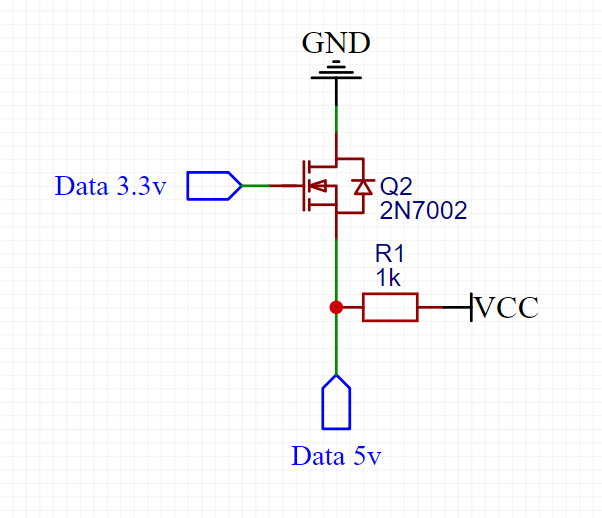
So circling back to the schematic I sent earlier, does it make sense in this case? I noticed that maybe the transistor is directional, so that could be wrong https://ferdz.needs-to-s.top/3F1V3P7.png
 reef ravine
just to illustrate why they add heatsinks...
hoary canopy
I don't plan on passing in anywhere close to that much power, so I'm not worried
pine bramble
There's a good datasheet on Adafruit

Because the Arduino (and Basic Stamp) are 5V devices, and most modern sensors, displays, flash cards and modes are 3.3V-only, many makers find that they need to perform level ...
reef ravine
in the above the drain and source need to be flipped and ground is by convention shown on the bottom
pine bramble
hoary canopy
Oh that looks pretty useful!
Thanks for that, I'll order it so I can play around with it
hoary canopy
in the above the drain and source need to be flipped and ground is by convention shown on the bottom
They need to be flipped due to the polarization, right?
reef ravine
it's late here i gtg, good luck with your project!
look up N channel and P channel fets
hoary canopy
Thanks for all the help! Really appreciated
pine bramble
@hoary canopy This is the MicroChip document:
MicroChip Compiled Tips 'n Tricks Guide
http://ww1.microchip.com/downloads/en/DeviceDoc/01146B.pdf
iirc it covers level shifting and maybe other topics.
Section/page 8-3
Chapter 8:
3V Tips 'n Tricks.
Figure 6-1 (on page 8-6) .. in particular ..
.. is an example of what I remembered from this document.
TIP #6 3.3V → 5V Using a MOSFET
Translator
In order to drive any 5V input that has a higher Vih than the Voh of a 3.3V CMOS part, some additional circuitry is needed. A low-cost two component solution is shown in Figure 6-1.
✈️
TIP #11 5V → 3.3V Active Clamp
One problem with using a diode clamp is that it injects current onto the 3.3V power supply.
In designs with a high current 5V outputs, and lightly loaded 3.3V power supply rails, this injected current can float the 3.3V supply voltage above 3.3V.
me: I had no idea that was true.
I often wondered where the 'bad thing' goes, when you clamp to the supply rail.
Apparently, the 'bad thing' is what they're calling injected current and its effect is to raise the rail above (say) 3.3V.
 obtuse spruce
@pine bramble - that doc is a gem! full of all sorts of useful bits - and most applicable beyond just PIC devices. -- I went digging for more and found they run this whole site: https://microchipdeveloper.com/ which also has tons of useful info.
Thanks for posting it and bringing it to our attention!
 gaunt glacier
I purchased an esp32-s2 after having worked with the esp8266 for a while, but after trying to look up tutorials on it, it seems it doesnt have much support since spring/early summer. Has this changed much?
stuck coral
Its brand new, I saw Scott working on it last week
There should be a development branch of whatever you are using
gaunt glacier
cant find much material on it, and last i read Arduino is not very compatible with it yet. As in you cant even upload from the IDE
stuck coral
Yeah that makes sense, its brand spanking new, check out scotts streams on adafruit im sure it will fill you in on the current state
 green heath
Is anyone else having a terrible experience with IDE 1.8.12? Constant crashing, freezing being slow
stuck coral
Lol, yep, I use PlatformIO
green heath
Right now it froze my taskmanager
green heath
Yeah right. Only IDE does it but anyway
I was trying to test my GPS receiver with IDE
Since it should be powered but it isnt turnin on the statud led
stuck coral
You can say that, but hundreds of thousands of people use it on Windows, MacOS, Linux, and BSD and with windows machines with low resources or with weird Java installs causes issues and is the only trouble platform.
Might be a USB issue too
Windows and USB dont mix well
green heath
Never had these issues using xloader and codeblocks but well
stuck coral
You can do embedded development in codeblocks?
green heath
Yes
stuck coral
Well,. I guess its just a IDE so why not
green heath
XD
stuck coral
Neato
green heath
I need some help with my gps
I am using the GPS6MV2 with 5 volt (conflicting sources say it works on 5 volt) but the status light doesnt turn on
And i cant troubleshoot it in IDE right now :/
stuck coral
Well you started with Arduino IDE crashing, I suggest checking java and USB issues first since those are common windows issues, but ultimatly check out platformIO its way better arduino IDE. Let me check that model so I can get more info one moment
Which arduino board are you using?
green heath
UNO
Technically i want to know how serial works of an avr
IDE just makes me check if all the parts work
stuck coral
I dont really know what you mean, the IDE is just a place to edit text with the toolset integrated, not sure what your last point was. What part of serial do you want to know about? And how do you have this GPS connected to the UNO?
Be careful using that GPS, 3.3V logic
green heath
I program in C and for neat personal benefit i wanted to learn how to program serial.
The gps is connected to the arduino with 5v and ground. Tx en rx are not attached as of now
stuck coral
Well in Arduino I would use the built in Serial library, but AVR serial implementations are platform specific
green heath
Yeah so. The first tutorial that i followed didnt mention it at all
Another said it as an internal logic converter
And I am thoroughly not amused
stuck coral
Typically there is a block of registers that are used for configuring serial, and a few IRQs that are triggered when you get data. To read and write there will be registers you can read and write to
green heath
Thanks but right now I need to know if the gps still works. Its quite expensive if you ask me
stuck coral
Sure, are you using a module with a GPS6MV2 on it? IF so can you link me to the module
green heath
Um store site, datasheet or picture?
stuck coral
Store site for now
green heath

TinyTronics
Een GPS module die werkt met UART (TX en RX) signalen. De bijbehorende GPS antenne wordt meegeleverd.Specificaties:Spanningsbereik: 3.3-5V DC
Spanning TX en RX signalen: 3.3V (let op: gebruik een level converter voor het RX signaal als je een 5V microcontroller hebt)
Standaard...
stuck coral
Okay, got it, thanks, can I see your setup?
stuck coral
It looks like the ground is disconnected to me
And can I get a close up of the solder on the pins?
green heath
It's unconnected because i keep reading 3.3 v or 5v on different sites. I have attached it to 5 v already
stuck coral
So that board is able to regulate a 5V supply to 3.3V so connect the ground, but leave the serial wires unconnected for now
We should be able to safely read the data from the GPS, but trying to send data to it might damage it
green heath
Camera isnt focusing on the solder
stuck coral
I see unsoldered pad, it looks like you need to redo those joints from here
It doesnt have to be super close
green heath
stuck coral
Oh that looks way better up close
So if you connect the ground wire on the module to the same ground as the arduino, and you feed in 5V nothing happens?
stuck coral
Just for now do you want to disconnect the power from that?
Just to remove as many potential issues as possible, we can readd it once we get the GPS working
green heath
Nothing
stuck coral
Okay, so from the GND pin on the arduino you have that going to the - rail on the breadboard, then there is a wire from there to the GPS? And a wire from the 5V arduino pin to the + rail on the breadboard with a wire from there to the GPS VCC?
green heath
Right now? Directly going to the arduino
stuck coral
Oh okay, and the Arduino LEDs are still on?
green heath
Yes
stuck coral
Do you have a multimeter?
green heath
Yes
stuck coral
Can you test the voltage between the VCC and GND pins? It should read 5V. Then we can test for the 3.3V rail
green heath
But dinner is ready so i will have to take a break. 30 minutes or so
stuck coral
Sounds good
stuck coral
When you get back please just let me know what the voltage here is, if you see ~3.3V then try bringing it outside and see if it suddenly starts flashing
Sorry the red circles are thin
stuck coral
If you have 3.3V supplied from the output of the regulator, either it outputs all the time or only when it has a lock, I cant see which on the data sheet.
It either does not have a lock, or does not work
green heath
Ok. But do i keep supplying 5v or 3.3 v?
stuck coral
5V, didnt you test the 3.3V rail with the multimeter?
green heath
No
stuck coral
Oh. can you do that for me?
The picture I attached shows where to probe
Keep 5V attached
green heath
Measures 3.3 volt
stuck coral
Then the module should be powered and working
green heath
Ok let me look outside
Even cellphone reception can be hard to find inside
Nothing
stuck coral
Okay, hold on lets see if we can get any serial data from it
green heath
I cant measure anything outside
stuck coral
Connect the module's TX to pin 4 but do not connect the pin marked RX on the GPS module
#include <SoftwareSerial.h>

SoftwareSerial ss(4, 3); // GPS Module’s TX to D4 & RX to D3

void setup(){
  Serial.begin(9600);
  ss.begin(9600);
}


void loop(){
  while (ss.available() > 0){
    byte gpsData = ss.read();
    Serial.write(gpsData);
  }
}
Then open a serial port to the arduino
green heath
Delft
I might need to walk or drive a bit around to get a reading
Btw thats the nearest city
stuck coral
Weird, I would think that part of the world has more then 2 GPS sats nearby
green heath
Yeah I found it weird as well haah
I have a gps navigation in the car that almost always has connection
stuck coral
Hm, well try to upload the code I gave you, is anything sent over serial?
green heath
Will have to restart to unfreeze IDE 😅
stuck coral
If it freezes for a while, I find that is usually a USB issue which is pretty annoying.
Arduino IDE is old
Works great on everything but windows 😆 But we need a more modern IDE
green heath
Well its not just ide it's taskmanager as well
stuck coral
Still might be a USB issue, the "executive mode" as windows USB driver runs in is crap and its amazing we still have these problems in modern computing
Sad the NT kernel never was what it could have been
stuck coral
The VCC input can use 5V, but the IO is 3.3V
Which is why I said not to connect the RX pin
green heath
Aight i will upload the sketch first incase one of the pins is written as output
HAHAHAHA. It froze the ide as soon as I attached it xD
stuck coral
Yeah, USB, are you using a laptop or desktop?
green heath
Laptop
stuck coral
Weird, maybe try another cable
green heath
Btw this is aftrr i uploaded the sketch
stuck coral
Usually the issue is front panel desktop USB connectors
green heath
Thats going to take a while to find
I will try again and then on my deskopt back panel
stuck coral
If you're having the issue with the laptop, I am going to guess its the cable
Might also be the arduino if its a cheap clone but unlikely
green heath
Can I use serial monitoring software?
stuck coral
Yeah, Putty works nice but anything should work
stuck coral
What does it say?
green heath
stuck coral
Nice! Im not sure how to decode it but it lookg like you dont have a lock
Which might be why the LED isnt blinking
green heath
I am inside right now so that explains that. And my phone cant get a lock either
Well so far so good :D :D
Also about the IDE. I attached the cable to the next usb slot over
That didnt make a difference haha
Oh well thanks alot :D. Now i need to figure out the serial in C
stuck coral
Give platformIO a try, at least its multithreaded so any USB or serial issue doesnt block the IDE thread
And which serial implementaion?
You are using two
green heath
Rx and tx
stuck coral
You are using hardware and software serial
green heath
So i can read the gps and display it on the lcd
green heath
My goal is to exercise with string functions and learn how to program the hardware serial
stuck coral
Try not to use strings
Character buffers are better in C, I dont see why you would need strings here
green heath
For LCD so i can output a string to the lcd
stuck coral
Well "string objects"
In C, there isnt a string, there are character arrays, and string objects
green heath
Yeah yeah haha. Thats why i need to learn how to use char arrays better xD
stuck coral
In other languages, in the background they are using string objects, but that uses a lot of memory when people just default to using string objects
A "lot" in the context of systems programming anyways with the microcontroller
green heath
Oh yeah the overall design i hope is going to be a walkie talkie sized speedometer that i can attach to my belt and measure my speed on my bike, during horseback riding and such
stuck coral
Is that your final display? 😜 Looks a little chunky
shell palm
@shell palm It ought to work fine, the input high threshold is 2 volts, so 3.3V logic should control it without needing level shifting. Make sure your power pins are hooked up appropriately for your signal levels, and everything shares a 0V reference.
@north stream Thanks for confirming for me that it should be working. After trying a million different things the problem ended up being the pinmode had to be set to output on Teensy while on Pro mini it wasn't needed. I overlooked pinmode as it was not included in the X9C library example version I choose to use and didn’t effect the programs execution on a 5v Pro mini. Again thanks a lot, now I can finally complete my projects hardware upgrade .
north stream
Good job tracing that down
green heath
@stuck coral i have another 16x2 display. I got this one on school after i soldered my older one wronf 😜
stuck coral
Got it, lol
green heath
The arduino will become a single 328p. I think the biggest component will be the 3 aaa batteries
stuck coral
If your display supports 3.3V operation, I recommend using a 3.3V board, then you can connect the tx of the display, and its easier to use a battery
In fact, I recommend the Adafruit feather, its small, it comes with a battery charger and connector while operating at 3.3V.
Then you just have the display atop the feather atop a battery, nice and compact
green heath
Oh no product placement. I will have to take a look xD
stuck coral
Well and the GPS thrown in there somewhere
I dont work for adafruit, but honestly even at work I use Adafruit, I have deployed a ton of LoRa mesh extenders that are just the Feather M0 w/ SX127x because there was just no reason to spin my own board. They had a battery circuit for backup, but were plugged in most of the time so the fact they aren't designed for super low power operation wasnt a big deal
On of my jobs at work is to reverse engineer competitors products and I use adafurit boards to interface to them
green heath
Mmmh i have taken a look. I am unfamiliar with other boards than arduino. It seems quite a bit more expensive than say a nano or just an atmega
stuck coral
When I deploy remote programmers, its just a Pi Zero W I got from adafruit. I have learned dont reinvent the wheel when time is money, and so far over years of buying adafruit products I can be sure its good quality.
green heath
Also thats a cool job
stuck coral
There is a premium, not gonna lie. Thats the least cool part of my job 😉
green heath
Haha. Well i am going to have to survive 3.8 years of advanced mechatronics first xD
stuck coral
But since we collect biomechanical data, if we find a competitor who produces bad data, I reverse engineer it, and find out why. Then there is a guy who writes whitepapers about why our stuff is just way better.
I give him the data and we make cool graphics
Last one was pretty bad, I got a trace of their PSU output and we overlayed it with the output and proved their software low pass filter was implemented quite poorly. Not to mention their hardware was so bad
green heath
Quite honestly
This project covers half of my next semester of AVR programming. Char arrays, interrupts and timers.
stuck coral
Nice, the hard part is doing it without Arduino 😉 Just GCC and VIM
Also, did you mention the XC toolchain earlier? That works too but Ive found issues with it
green heath
Your job sounds way over my head haha. I cant even troubleshoot on my own xD
I use xloader to uoad and codeblocks for development
But i might switch to atmel studio. I heard that programs quite well
stuck coral
Kinda, just to me the AVR days are over and I never got into atmel studio
There are a few places where thats not true, but for the most part
green heath
I am generally not a fan of arduinoese. It only shows how and not why it works
stuck coral
Honestly Arduino turned into python for me, I grew to dislike it as well.
green heath
I get python next year if i survive for that long. Looking forward to it
stuck coral
I use it, but I want something better, and I think wiring can be a lot better
I dont like python, I did at first
green heath
Well i like c right now because i cant do anything else xD
stuck coral
Ive been learning rust recently, and last week I compiled two blinkies one in C and another in Rust, they were the same size I am running out of reasons to continue with C
Im working on a project right now but I think there is a happy solution to all my problems
green heath
Yep. I wish there was a c+ but not quite c++
stuck coral
Should try rust, there are methods like in golang and similarly there are no objects
Also the rust slice implementation makes so much sense, and the syntax makes you aware of what you're doing in memory
And compiled binaries are guaranteed memory safe in code not in a unsafe{} block, its as fast as C, and the toolset is modern
green heath
I will have to take a look. I know of a C openGL framework with rust bindings. Could be worth it
Its called raylib btw
stuck coral
I am compiling a rust library to use in a Android, iOS, Linux, MacOS, and Windows app, its super cool.
You can bind any C code you want into rust
And vice versa
green heath
Nice
north stream
Heh, I heard about one company that built a microscope illuminator with a power supply that acted like a pulse amplifier, so even a small surge on the incoming mains would burn out the bulb. They did a ton of testing on the bulbs and wiring, but it wasn't until someone who really understood electronics looked at their power supply before they found out what the real problem was.
stuck coral
The product I am talking about costs tens of thousands of dollars and I wish I could share pictures and stuff because it looks like someone threw a sticky note at the first person they saw in a university arts wing and told them to make a circuit board. They bought a off the shelf data collector, and wired in their own PCB that was total garbae. They for some reason had a 24V DC input even though the entire thing ran on 5V, and even though the product in question requires USB anyways which already has 5V, they were using linear regulators for 24V-5V, but they have 3 because there was probably too much heat from one, the PCB is huge because its just acting like a heat sink due to three linear regulators dissipating 10W and the case is enclosed, and even with the linear regulators, they didnt put nearly enough caps on the outputs and the 5V rail is garbage which they are feeding directly into their sensors
Basically just a negligent rip off
north stream
That's depressingly common.
stuck coral
We get all their customers and imagine being the poor guy whos only job is to clean up years of garbage data. They didnt train anyone how to use their product either. And I know, (shh) the company I work for has a terrible PCB, but its not nearly as bad as everyone elses.
I dont understand how so much money is thrown around for garbage, and I know its common, it just amazes me
Cant wait until my version is out, its cheaper to make than everyone elses, has more features than everyone elses, is more user friendly, is more accurate, and the output isnt garbage
pine bramble
My boss said there were transistor radios with all three legs soldered to the same pad on the board, just to up the count, as in those days they advertised how many transistors there were in the radios sold.
 pulsar junco
I remember the megapixel wars, kinda similar
stuck coral
Thats true
So @pulsar junco speaking of that era
I was looking at a picture from a 2004 Sony digital camera I had, and compared it to my phone. The phone's quality is garbage am I the only one who thinks this?
pine bramble
It is actually a process you go through, to tell the truth and to be honest. It doesn't happen automatically. It's a willful activity. ;)
pulsar junco
My phone is older and it's just OK. I used to know something about digital cameras but I've forgotten.
stuck coral
I have like, a modern flasghip
pine bramble
That works for things like pride in your work as well.
stuck coral
The image depth is sooo bad. And I quit my last job because they told me to lie to a customers face about their security, I love taking pride in my work
pulsar junco
ages come and pass and little surpasses film
stuck coral
It feels like we've lost the science of taking a good picture to begin with vs just applying a lot of processing
Even just ignoring film, just digital photos
A modern nice DSLR should be okay, but the phones camera is not as marketed to me
I dont see how I can take a 2004 camera and beat the 2020 phone the way its marketed
pine bramble
Was there something you wanted to know wrt Arduino, since we're here?
stuck coral
No I think the last two people needing help are good to go
pine bramble
;)
stuck coral
I just kept talking
north stream
That nonsense was prevalent in the tube days too: they'd add "ballast" tubes (basically resistors in glass housings) to up the tube count
stuck coral
I mean, at leas the final product functioned correctly right?
I consider their product to be so bad as to call it unusable. Like when you jump, it reports you jumped 11 feet in the air if you do it when the low pass filter buffer empties
north stream
I'm amused by the part number of this R2D4 ballast tube
stuck coral
Lol, your favorite steampunk star wars character
north stream
Some of them did have a circuit function, varying their resistance to provide (more or less) constant current with varying supply voltage and load. They were constructed of iron wire in a hydrogen atmosphere.
pine bramble
I remember those.
green heath
I have been reading the setbaud.h and it includes a function to set the Uart. but it just outputs a bunch of error messages that some registers and values are undefined
stuck coral
Its hard to follow Arduino code, its links in ways that are just impossible to follow
green heath
yeah, not to mention the code differs from the USART C code example in the datasheet
 raven wing
This is my current prototype setup. Does anyone have a neat idea of how I can eliminate the breadboard?
stuck coral
Use a protoboard or make a PCB
raven wing
I have some perf board here I will try to use next.
green heath
also tiewraps are a cable managers best friend
raven wing
So, think I should solder a wire directly to the perfboard (for my GND, for example) and use a female header on that wire to connect to a male GND pin on the arduino?
There seem to be so many ways to connect parts. Trying to get a feel of best practices
pine bramble
The only one I don't like is a male pin on the end of a wire (Dupont style).
raven wing
Is there an easy way to get 4 to 1?
Like, I have 4 cables that all need to go to 1 pin
*wires
pine bramble
I strip them all and then crimp them together with a crush-able crimp.
squid geometry
raven wing
"crushable crimp"
pine bramble
crimp connector
 raven wing
Hm. Not quite what I'm looking for
Crimp, either.
Wish someone was in my brain
Not that you aren't being helpful
pine bramble
I get the same way about music.
north stream
I like these for joining wires https://www.adafruit.com/product/874

These are like the fancy electronics equivalent of the wire nuts electricians use to bind wires together. They are a lot easier to use as well! Each block connector has a metal block inside ...
raven wing
Maybe it could make sense to just sodler a perf board directly to the back of my pro micro
*solder
 grand basin
Hello, I have a question with a little bit of code. I forget, do I post the code here or should I host it somewhere and link here?
vivid rock
@grand basin if it is short (like 10 lines), post it here; otherwise, upload it to pastebin or a similar service and post link here
green heath
this is odd, I get a fix for my GPS when coding in C. (I litterally just uploaded C code.) wouldve been nice to see in arduino IDE xD
 zenith orchid
Anyone free to help me with my code...
north stream
Maybe describe your issue, some people have different areas of expertise
zenith orchid
It's pwm control for bldc motors that have hall effect sensors...I'm trying to write the code for the controller for each of the six lol motors :P
north stream
Sounds like a lot of keeping track of state and timing
zenith orchid
Kinda a weird one....but I'm pretty hyped....so far my code can move two wheels.....and I think I could easily expand that to four or six....but the issue is I'm sending commands through the serial monitor.....when I'd like to have wireless control....I have a esp3266 to run the website and stuff. And it's not too bad so far....I haven't had it on the ground quite yet but
I don't have the esp3266 hooked up quite yet though...just have it in my house to use with the project
north stream
Nice! Motion is good. Is the ESP running the motors or acting as a WiFi coprocessor?
zenith orchid
It's not doing anything yet, hasn't been included in the project...currently I've just been using pins 1 - 13 as pwm control for the escs I got
Problem is there's no data sheet for them
On a mega lol
Sorry forgot that part
So I've got my mega hooked up to my pc and I've got three wires plus gnd running to the mega from one esc I could hook up more to get the hall sensor position....but I'm not sure that's needed or is possible with the mega
This is how one is hooked up
Let me get a better photo
This is the exact board I'm using
grand basin
This section of my code sends MIDI CC values. The other section of the code loads an array of EEPROM addresses when the button is pressed, and replaces the value of the pot, with the value stored in EEPROM. Think presets on a synth.
The intention of the abs() in this code is so that the EEPROM value doesn't perform the undesired behavior of 'snapping' to the value of the pot if the pot is jittery (jumping between 2 values).
It works fine, but the abs() function limits the resolution of the CC value (so if threshold = 2, the CC value will go from 2-4 instead of 1-2-3-4). 0 - 127 is the same distance, but it skips numbers.
So let's say I don't care about jitter at all. What I desire, is for the EEPROM value to overwrite the value of the pot, until the pot is only turned a certain amount just once, instead of constantly following the pot. That's where I'm stuck. Please let me know if that doesn't make sense
        initPot[i] = map(analogRead(potPin[i]), 0, 1023, 0, 127);
      if (abs(initPot[i] - lastInitPot[i]) > threshold) {
        lastInitPot[i] = initPot[i];
              potVal[i] = initPot[i];
               MIDI.sendControlChange(CCChannel[i], potVal[i], 1);
      }
}```to simplify all of that, what I want is:
- press EEPROM.read button > "potVal" is value stored in EEPROM
- until initPot changes by an absolute value of say, 8
- then potVal = initPot, with no threshold (give me all the jitter)
green heath
I need some help with USART.
- I am receiving things
- the Tx/Rx leds are not saying its recieving things.
this is in c
 */

#include <avr/io.h>
#include <avr/interrupt.h>
#include <util/delay.h>

#define BAUD 9600

#define FOSC F_CPU // Clock Speed
#define BAUD 9600
#define MYUBRR FOSC/16/BAUD-1
#include <util/setbaud.h>

void USART_Init( unsigned int ubrr)
{/*Set baud rate */
    UBRR0H = (unsigned char)(ubrr>>8);
    UBRR0L = (unsigned char)ubrr;
    /*Enable receiver and transmitter */
    UCSR0B |= (1<<RXEN0);
    UCSR0B |= (1<<TXEN0);
    /* Set frame format: 8data, 2stop bit */
    UCSR0C = (1<<USBS0)|(3<<UCSZ00);
}

uint8_t recieve_Byte(void)
{
        loop_until_bit_is_set(UCSR0A, RXC0);
        return UDR0;
}


int main(void)
{
    char byte = 0;

    USART_Init(MYUBRR);

    lcd_init();
    lcd_clrscr();
    lcd_puts("hello world...");

    while(1)
    {
        byte = recieve_Byte();

        lcd_clrscr();
        lcd_putc(byte);
        _delay_ms(1000);
    }


    return 0;
} ```the output of the LCD screen changes per byte recieved. yet the Rx/Tx leds dont show they are doing anything
oh yeah its working. I am getting the right values so far when I put the recieve byte into a character array
vivid rock
can someone confirm my understanding that on Adafruit nRF52840 boards (at least on ItsyBitsy), ADC is configured to use 3.6v as reference voltage, instead of usual 3.3v?
It seems so from reading https://learn.adafruit.com/adafruit-itsybitsy-nrf52840-express/pinouts
More general question, is there some way of finding the reference voltage for different boards other than reading adafruit's learn guides? like standard macro VREF or something like this?
hoary canopy
@pine bramble Thanks for those articles you sent yesterday, I'm reading through the first one you sent, and this section got me confused. Wouldn't it be HIGH anyways because it's connected to the Vdd2?
 sage raven
Hey y'all. I'm brand new to electronics and Arduino, and I could really use some help!
I'm trying to use an Arduino Nano (3.3v) to switch a 12v LED panel for my aquarium that has three leads:
- cathode
- anode white LEDS
- anode blue LEDS
The LED panel came pre-installed with a 3-stage switch (on white, on blue, and off), and I'd like to replicate that behavior with my Arduino. I've successfully used an N-channel MOSFET to control a single color on the panel, but I'm struggling to design a circuit to control both colors.
My confusion is due to the common cathode between the sets of LEDs. All similar examples I'm finding online are for RGB LED strips which usually contain a common anode I believe?
Does anyone have an any pointers on how I can accomplish this? I've seen online that maybe a comparator may be a better option in this case rather than a transistor?
pine bramble
Is there an arduino library like keyboard.h that supports XF86 keys?
 cedar mountain
@vivid rock I interpret the docs the same way... it's got a 0.6V internal reference with a 1/6 gain on the inputs, so effectively a 3.6V ADC scale. Unusual, but makes reasonable sense.
vivid rock
@cedar mountain thanks!
I wish there was a way to get this info in code, like a #defined macro. Would make it easier to write sketches which could run on different boards without modification
cedar mountain
Or just an API that returns a voltage instead of a count, which would also deal with variable bit resolution, etc.
vivid rock
For now I managed by including this in code
#ifdef ARDUINO_NRF52_ITSYBITSY
#define VREF 3600L
#else
#define VREF 3300L
#endif
but it only covers one specific board...
reef ravine
@sage raven use P-channel MOSFETs and do high side switching, see https://www.baldengineer.com/low-side-vs-high-side-transistor-switch.html. Depending on the positive supply voltage you may need an NPN to interface between the mcu and the FET. (One reason 4 wire RGB strips are common anode, low side drivers are easier to implement on mcus.)
 fiery merlin
i've got this small fan with 2 wires and it isn't being turned on with PWM
I've got a periodic message going to the serial monitor and i tested wire continuity so it is running
and the code works fine for an LED
vivid rock
do you connect the fan directly to pins of arduino or similar board?
fiery merlin
breadboard
using an arduino uno, pin 3
Orange is fan positive, white is fan negative
sage raven
@reef ravine Okay I see, thanks so much for your reply. My supply voltage is 12v and my logic level output is 3.3v. Obviously I’ll need a driver to boost my Arduino’s output signal and shut off the MOSFET. Any pointers on picking parts for this application? Super new to electronics
vivid rock
@fiery merlin arduino can only provide very small current direclty, maybe 20 mA - enough to light up an LED, not enough to run a motor. If you want to run motors, even small ones, you need to use a transistor/mosfet, or a dedicated motor driver
vivid rock
motor drivers are easily available and inexpensive
fiery merlin
no the bad news is much more complicated than that
i am terrible with circuitry/wiring, it just doesn't make sense to me, but this project i'm on
falsely advertised that its relevant for several majors including mine
when literally only electrical engineering is applicable here
i still dont understand how what i have works entirely and it's extremely simple
vivid rock
good news is that many components can be treated as black boxes. You do not need to know what is inside motor driver, all you need to know is that it takes low-current input such as pwm signal from arduino, and produces much higher current suitable for driving motors at the other end. This makes life much simpler
fiery merlin
is this something i could get in an actual store
vivid rock
online is easier and faster
which country are you in?
vivid rock
you can get one on amazon - with prime delivery it will be there in two days
fiery merlin
that is not quick enough 😦
vivid rock
I mean.. of course one can pay $25 for overnight delivery from digikey...
or maybe buy some toy car in nearest toy store and cannibalize that
fiery merlin
it gets better because there's no documentation about any of the parts in this, which were all made in-house by previous semesters on this project
vivid rock
does the instructor know anyhting?
fiery merlin
no, and several weeks of trying to contact the guy who did this went nowhere
this is whatever the polar opposite of pog is
vivid rock
then I think it may be easier to begin from scratch, parts are cheap
overnight delivery is expensive, though
fiery merlin
although as to not be completely useless i might just dedicate the last few weeks of the semester to actually making thorough documentation, and telling the professors to cut everything that isn't electrical off the list
that is not within a realistic time span... this was a last-resort effort to get something to work as intended
vivid rock
have to run
if you happen to have some transistors lying around, here are some docs on how you build the circuit yourself
https://cdn.sparkfun.com/assets/resources/4/4/DC_motor_circuits_slides.pdf
fiery merlin
also this is further complicated by the existence of 3 other components past the fan, 2 as i mentioned were developed in-house and i have literally nothing on how they work aside from hearsay of someone else who sorta worked with them
mate idek what a transistor does, i was lied to about my major being relevant to this project and got stuck with an EE's task
vivid rock
if you have time, get motor driver, e.g. https://www.amazon.com/Controller-H-Bridge-Stepper-Control-Mega2560/dp/B07WS89781
then you do not need to know anything about transistors
fiery merlin
well i could but it won't deliver before the showcase... might as well bite the bullet :/
well, thanks for the help anyways
pine bramble
@hoary canopy I haven't had my c0ffee (or even enough water to drink) as I just got up. 77 new messages here after yours. ;)
@pine bramble Thanks for those articles you sent yesterday, I'm reading through the first one you sent, and this section got me confused. Wouldn't it be HIGH anyways because it's connected to the Vdd2?
@hoary canopy I guess we really do need the quoty-quote now. ;)

BSS138 level-shifter board from Adafruit is one of their oldest.
http://adafru.it/757 and contains the above App Note on its listing.
NPX AN10441
@hoary canopy Pull-ups act on circuits that can go either way without a lot of current flowing.
They influence which logic level is asserted.
So a pullup brings a logic pin to a HIGH state in the absence of something trying to bring it LOW.
In your highlighted scenario, something has asserted a bus line LOW on the 3 volt side (the left).
That's a stated condition (we don't see just what does this; it's assumed one of the devices there is doing it, though).
The paragraph you highlighted describes what happens, once a 3.3 volt logic device has asserted a bus line LOW.
The best way to answer your question is to construct this circuit on a breadboard, and manually assert a bus line LOW - and take measurements.
Probably just measure the potential difference from ground of each line, and also, the current flowing through parts you may otherwise suspect are drawing very high current (They are not; the measurements prove they're not).
🛩️
I found this scheme confusing and I wasn't entirely convinced, on first read-though (maybe two years ago).
Now, because I accept it as fact, I don't balk (at all) when I read the description of how it works.
- - -
I'd have to think about it, but my intuition suggests the discussion on the physical circuit that makes up a GPIO port pin, in both INPUT and in OUTPUT modes, would help here, to understand what the rest of the circuit is doing (and looks like).
If I was teaching this, I'd have a slide I'd show right about now, with the basic layout of a GPIO pin, showing how it gets reconfigured as an INPUT or an OUTPUT ..
..(push-pull, or open drain, depending on .. I don't know what. ;).
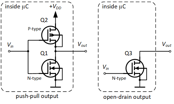
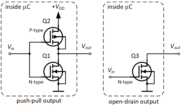
Wrt push-pull vs open-drain output:
https://circuitdigest.com/sites/default/files/inline_users/u1759/05outputs.png
Sorry, I think it just occurred to me: I meant to differentiate between Open Drain and Open Collector .. that'd be mosfet vs bipolar junction transistor.
But the above (accident/conflation) helps me, because it shows a pair of mosfets connected push-pull, and contrasts that output with an open drain output.
So you could implement the equivalent using BJT's and still have either push-pull, or open collector (this time).
🛬 The open drain, to me, looks like it can only sink current to ground (cannot source current). I may be wrong about that.
I think one (or both) of the i2c bus lines (SDA, SCL) must be configured on a GPIO only as open drain, because of the signalling used.
Basically, a device on the far end of the bus can bring the bus low - which amounts to (asserting) a ground.
If you were push-pull that'd be a dead short and very high current.
When (in contrast) you want to light up an LED using a GPIO pin, you set it to output, but not open-drain: you set it to push-pull, instead, so that it can (this time) source current, rather than sink current.
north stream
Or hook the LED to a positive voltage (via a current limiting resistor), at which time an open-drain (or open-collector) output can operate it too.
And you're right, open-drain and open-collector outputs can only sink current.
 fallen jetty
Hello everyone,
I'm currently trying to program an adafruit huzzah32 (esp32) board via arduino ide.
Unfortunately I can't find the board on the COM Port. When I unplug and plug the board back in,
even when I restart arduino ide - it can't find the board.
I installed the drivers for windows (CP210x_Universal_Windows_Driver) and I used
espressif -> arduino-esp32 install instructions from github as well.
Anyone has an idea what I'm doing wrong?
north stream
Some USB cables are power-only, and won't let you communicate with devices.
fallen jetty
this is a cable I used already for another project to program a board. But not a esp32, it was something else (I can't remember at the moment)
north stream
Okay, so it's not the cable. The next thing I'd suggest is finding out if it enumerated as a USB device.
fallen jetty
How would I find that out.
When I plug it in, Windows wont "react". No Sound, no popup
north stream
I know how to check it on Linux and MacOS, but not windows, but it sounds like it's not enumerating.
north stream
The normal process is that the device enumerates on USB, then the computer uses the information from that (vendor ID, product ID, etc.) to attempt to associate it with a driver, then the driver attaches to the device and exposes an interface (like a COM port) for programs to access it. Debugging the process basically involves figuring out which phase failed.
pine bramble
(Thanks for those comments @north stream )
@fallen jetty what bodger just said.
In Linux, you can always see some change when a USB device is plugged in.
(soft 'always' there's usually a caveat somewhere)
You can get a liveCD and boot Linux on many machines (including using a USB thumb drive instead of a CDROM) and prove the hardware that way. May be more than you want to take on, of course.
There are a lot of articles showing how to troubleshoot not-recognized USB devices.
Click on the Power Management tab and uncheck the Allow the computer to turn off this device to save power box.
from
https://www.online-tech-tips.com/computer-tips/usb-device-not-recognized
That's one I haven't seen before.
Until it is recognized, it is in no way an Arduino-related problem. It's an operating system problem (in this case, Windows).
reef ravine
what if the CP210x chip failed on the board? that wouldn't be a windows issue
fallen jetty
mhh @reef ravine, that could be. luckily I have a second one (which i forgot about until just now xD)
So I'm going to try the second one now
reef ravine
your best bet, see if that cable works on the other board, if so it's the board, else it's the cable
fallen jetty
well, second one works...
i soldered the pins on the first one... maybe I destroyed something 😦
reef ravine
check VERY carefully for shorts
pine bramble
caveat noted (good call)
Presumption is that the hardware (other than the USB cable) is fine.
reef ravine
i'm a hardware guy, i always assume hardware failure 😉
pine bramble
check for /dev/ttyUSB in linux
@reef ravine For students I like to assume the hardware's fine, as they so often just expect it died.
So that messes with things when the hardware in fact is at fault. ;)
Kind of like viruses/trojans in 1989 .. people leapt to the conclusion (that one is present) when that was almost never the case.
reef ravine
it's like the old adage, if all ya have is a hammer...
reef ravine
i fear i do sometimes hand out disinformation, but never deliberatively 🙂
pine bramble
;) yeah me too.
I used to know what I knew.
now, it's more like remembering than knowing
fallen jetty
i checked for shorts, nothing found
now i plugged it back in and windows recognizes the board
pine bramble
@fallen jetty It's good to put stuff aside when it's not urgent.
 dark shard
Good morning yalls I'd like to ask your advice on a library I'm trying to use but I don't want to derail the conversation, would you be willing to @ me if one are you are willing to hear me out?
When it is a good time that is.
reef ravine
LOL, my theory: you are born with no knowledge, it grows until you know everything at 18, then you know less and less 🙂
dark shard
LOL, my theory: you are born with no knowledge, it grows until you know everything at 18, then you know less and less 🙂
@reef ravine LOL
pine bramble
@dark shard I'll look in #general-tech and see what's going on there.
dark shard
Oh, Roger. I assumed with all these sub groups I needed to go to the specific. Thanks for the tip!
pine bramble
It's open. I'll see if I can help, there.
dark shard
Thank you kindly.
reef ravine
<goes off to day job, have fun all>\
fallen jetty
Arduino now recognizes the com port
When I try to program it it says "done uploading" though, on the serial monitor I only see gibberish and the board itself does nothing :/.
Anyone available for a quick private chat to try to figure out whats wrong? I'm pretty new in hardware development, usually a software guy
pine bramble
I like to keep those conversations in public, since lurkers may benefit from what is discussed. ;)
 clear valve
@fallen jetty Check that your baud rate in your serial monitor matches the one in your code.
pulsar junco
Figured this is a good spot for bitmath questions
I want to ensure a number is between 1 and 3
by forcing it with a mask, is that possible?
north stream
(x % 3) + 1?
 north stream
You didn't specify a mapping...
pulsar junco
ah yeah I want to retain the original value that was passed in sorry
north stream
Maybe you wanted: ```
0 -> 1
1 -> 1
2 -> 2
3 -> 3
4 -> 3
Retain the original value if it's 1-3, then do ... something ... with values that aren't?
pulsar junco
yeah exactly, I was not clear
I can do it with an if statement but it's kinda hacky
north stream
x = (x < 1) ? 1 : (x > 3) ? 3 : x?
It's abuse of ternary operators: arguably hackier than using if
pulsar junco
what I had is (in python, sorry arduino folks):
if not 1 <= rows <= 3:
  Raise ValueError("rows must be 1-3 inclusive")
rows = rows & 0x03
if not rows:
  rows +=1
The second if is superfluous, as the first one catches the not rows (an obfuscated way to say "rows == 0")
pulsar junco
hm
north stream
You can either correct the value or throw an error, but doing both seems pointless to me.
pulsar junco
I kinda agree but I saw it in a lib and thought I'd see what I can do with it
it made more sense to me to return with an exit coide
code
north stream
You could add a "do what I mean" or "permissive" flag and correct it if that's set, otherwise throw an exception
pulsar junco
what do you mean by that?
north stream
if not 1 <= rows <= 3:
  if args.permissive:
    rows = 1 if rows < 1 else 3
  else:
    Raise ValueError("rows must be 1-3 inclusive")
You could invert the logic on the inner if since Raise interrupts flow and then fall through to the other clause 🤔
pulsar junco
what about
rows = 1 if rows < 1 else 2 if rows < 3 else 3
idk if that works let me check
north stream
That's equivalent to my other ternary abuse but worth a try
pulsar junco
I am trying to think of a simple bitmask that works but I can't think of one
north stream
It's not a bitmask problem, it's an inequality problem (Graphing Calculator is great for illustrating such things)
north stream
Your valid value space is 3 values wide, bitmasks work with powers of two.
Not even then: ((rows - 1) & 0x3) + 1 yields: ```
0 -> 4
1 -> 1
2 -> 2
3 -> 3
4 -> 4
Unfortunately, bitmasks only work for ranges that are powers of 2. 0x03 matches a range of 4 values.
pulsar junco
could you not do 0x04?
north stream
Sure you could, but it would work even less well.
0 -> 0
1 -> 0
2 -> 0
3 -> 0
4 -> 4
Oh sorry I did that thing where I don't say my whole thoughts, I meant if you wanted values 0-4 to be valid could you use 0x04
but it seems not
Ah i see
north stream
Alas, that doesn't work either. A range of 1-3 is 3 values (not a power of 2), so it won't work with a bitmask. A range of 0-4 is 5 values (also not a power of 2), so it won't work with a bitmask either.
pulsar junco
darn you arithmatic
north stream
A range of 0-3 is 4 values, which is a power of 2, so that is achievable with a bitmask.
pulsar junco
/fundamental rules of reality
north stream
Now in base three, the rules are different!
pulsar junco


 north stream
It's more like the fundamental rules of binary, not reality
I had the amazing (dis)advantage of a mother who was a math teacher and started teaching me number theory when I was 3 years old. The difference between a chalk mark in the shape of "2", versus the actual number two. The difference between digits and numbers, and the existence of numbers outside of arbitrary bases or other representations. Heady stuff. Guaranteed to get me in trouble with math teachers until my later college years.
pulsar junco
until college I had very few math teachers with a background in math
"just focus on your times tables"
north stream
Same here. I got in big trouble for trying to explain negative numbers to my kindergarten teacher, who insisted the number line ended at zero, and anything past it was possibly the work of the devil.
pulsar junco
I guess they never overdrafted their account
so regarding the HT16K33, I'm trying to figure out what command I need to write to it in order to have it send back the key data.
it's not the key data address pointer is it?
north stream
It's just reading stuff from registers. You tell it you want to read 6 bytes starting at the key register address, then read in the 6 bytes.
pulsar junco
ah so it is the pointer then
north stream
Looking at my Arduino code, it does ```arduino
Wire.beginTransmission(i2c_addr);
Wire.write(KEY_ADDR);
Wire.endTransmission();
Wire.requestFrom(i2c_addr, (uint8_t) KEY_LEN);
then calls Wire.read() six times in a loop
pulsar junco
idk if I should move htis to the python channel, I just came here because this is the land of bits and bytes
what is the value of KEY_ADDR?
north stream
It's 0x40, right out of the HT16K33 data sheet
north stream
Yup. I vaguely recall the data sheet advises reading all 3 rows (all 6 bytes) every time, even if you aren't using all the values.
pulsar junco
it does
I just wasn't sure if writing to 0x40 would cause that
reading all at once that is
north stream
My circuit uses all 3 rows anyway (I'm using it with a 3x4 keypad)
The write just sets the starting address, then six reads read 0x40, 0x41, 0x42, etc.
pine bramble
Working on a button box/usb media controller for my desktop. button input is going to be setup as a 4x4 matrix keypad. I've got the code set and a working prototype. Now I'm building the actual button panel I'll be using. My question is which direction to I face the diodes? i.e. is power flowing from rows to columns of columns to rows?
north stream
It depends on which scanning library you're using and how you hook it up.
pine bramble
I figured it out. Just finished up getting the final product working electrically. Now I just need to sand/stain the case, and screw the Arduino down inside.
fallen jetty
anyone here got experience with adafruits 2.13" e-ink monochrome feather? I can't seem to get the display working :/
fallen jetty
yup
 wraith current
8266 or esp32 ?
fallen jetty
I try to use the epd example, but it doesn't update the screen
esp32
using arduino ide (so c code, not python)
wraith current
ok. because esp32 pins are different than 8266 pins. lemme check my code.
fallen jetty
oh.. that could be the problem, thanks
wraith current
pin defines for esp32 feather#define SD_CS 14 #define SRAM_CS 32 #define EPD_CS 15 #define EPD_DC 33
fallen jetty
mhh, I tried the same - though, I don't have SD_CS in my example codes
wraith current
Adafruit_SSD1675 epd(250, 122, EPD_DC, EPD_RESET, EPD_CS, SRAM_CS, EPD_BUSY);
oh these too #define EPD_RESET -1 // can set to -1 and share with microcontroller Reset! #define EPD_BUSY
fallen jetty
#define EPD_CS     15
#define EPD_DC      33
#define SRAM_CS     32
#define EPD_RESET   -1 // can set to -1 and share with microcontroller Reset!
#define EPD_BUSY    -1 // can set to -1 to not use a pin (will wait a fixed delay)

Adafruit_SSD1675 display(250, 122, EPD_DC, EPD_RESET, EPD_CS, SRAM_CS, EPD_BUSY);
that's what I have
wraith current
did you solder in all the pin headers to both boards ?
wraith current
hmm. can you post a pastebin of the entire code ?
fallen jetty
sure, give me a sec
Pastebin
Pastebin.com is the number one paste tool since 2002. Pastebin is a website where you can store text online for a set period of time.
wraith current
that's got the red color display lines in there.
fallen jetty
yeah, it said something in the comments, if you use it with the monochrome it will be light gray
oh.. maybe I deleted too much from the old code, I'll update it
ah nevermind, it uses predefined variables
wraith current
hmm. the example code looks ok to me. Sure you don't have mis-asligned pin connection between the boards ?
fallen jetty
well... not 100% sure. I'm not a hardware guy and have no idea how to check it properly
but the eink is a wing, so there shouldn't be any problems.
the huzzah was soldered by me, so it could be a bad solder
wraith current
post a picture of the two boards. It's not hard to connect them just one pin off.
wraith current
well definitly looks like pin 33 could use a better soldering job and that one is used for the EPD
fallen jetty
is it A9/33?
wraith current
yeah #define EPD_DC 33
fallen jetty
alright, I try to fix it, thanks
wraith current
touch on pin 32 as well, that the SRAM pin used.
and remove the SD card if you're not using it.
wraith current
good luck.
wraith current
fallen jetty
Is it possible to get rid of the debug output from the featherwing?
in serial port, each time the display updates I get ram address info etc
fallen jetty
@wraith current do you have a code example to display an image onto the wing?
 mortal bison
hello!
Im sort of new to Arduino, and i'm trying to clean my code up a bit
but im reading from a multiplexer and the pins it uses are defined as some sort of object {2,3,4,5}
I want to store this in a definitions area in my script to re-use it for multiple multiplexers
but I don't think this is correct pin muxSerial = {2, 0, 4, 5};
its not a pin, but is it an array?
mortal bison
do I declare pins are an int? what about analog pins?
I get 'pin' does not name a type
if I use int muxSerial[] = {2,3,4,5}
I get the following error convert '{muxPin_D1, muxSerial}' from '<brace-enclosed initializer list>' to 'AH::CD74HC4067 {aka AH::AnalogMultiplex<4u>}'
 deep salmon
hey guys, I need to find a timer that runs from a set time, something like 8pm - 8am. The thing is, it needs to turn on the circuit for 1 min every 20 mins. Any ideas, I cant seem to google correctly
JVR 12V Timer Switch Programmable Digital 12 Volt DC/AC/Solar Battery Powered - - Amazon.com
been using this, but it doesnt have enough programmable settings for what I need
zenith orchid
So I got my wheels spinning
With this code.
Pastebin
Pastebin.com is the number one paste tool since 2002. Pastebin is a website where you can store text online for a set period of time.
but......it's not very expandable ie. I have six wheels I'll need to control, and the way the code is now....you can change the speed on the fly...but I'd really one day like to get this thing moving with maybe a ps3 controller or something like that
wraith current
@zenith orchid nice, you the motors working. what was the problem before ?
zenith orchid
Yes I've got two of the motors working which is cool. That wasn't to bad to figure out.....but this code is really hard to work with......and it doesn't let you go wireless since commands need to be sent through the serial monitor
 humble spindle
Hi!
I'm new to Arduino and electronics and I'm seeking some kind of approval for a test I want to perform. So any help is much appreciated!
To give a little bit more background: I'm following a Udemy Arduino intro course but temporarily stopped since I needed to solder things... which I don't have the right equipment for yet.
In the mean time I bought an Adafruit Neopixel RGB 60 led strip 1 meter which I want to playtest (starting with running the strandtest light show example).
The documentation states that a capacitor is recommended to prevent power spikes and damaging the pixels. I don't have a capacitor right now.
**1. **Is my setup with a breadboard power supply at 5V enough to fix this? Or do I really need that capacitator? The breadboard power supply should regulate to a steady 5V no?
I'm using an Arduino Uno, which will be powered by the USB cable.
The strip has 4 cables: 2 black, 1 white and 1 red.
1 white (PIN 6) and 1 black(GND) are connected to the Arduino. A 470 Ohm resistor is in between the white connectors.
Other black (GND) and red (5V) are connected to the breadboard and it's power supply. Ok, they are connected clumsy but I don't have any other way of connecting them right now.
2. Do those connections look ok? Or do I need to change something?
3. The led strip also has wires at the end. Do I need to cut the strip to remove them? Or can I just leave them there?
Product: https://www.adafruit.com/product/1138?length=1
Info on basic connections: https://learn.adafruit.com/adafruit-neopixel-uberguide/basic-connections

You thought it couldn't get better than our world-famous 32-LED-per-meter Digital LED strip but we will prove you wrong! You wanted twice the LEDs? We got it (well, its 1.875 times as ...

Adafruit Learning System
Everything you always wanted to know about Adafruit NeoPixels but were afraid to ask
 topaz compass
Didn't realize udemy had such a course. Can you link to it? Coincidentally, I'm just about to restart an LED strip experiment myself. I'm fairly confident the answer to your 3rd question is NO, you don't have to remove the end wires on the strip. And yes, you should keep the capacitor, as the adafruit guide states.
humble spindle
@topaz compass thanks for the info. I'm following the Arduino Step by Step: Getting started course:
https://www.udemy.com/course/arduino-sbs-17gs/
wraith current
@zenith orchid I would suggest reading up on mqtt. It could work as a control protocol.
mortal bison
how do I use this?
template <setting_t N>
class PotSelector : public Updatable<> {
  public:
    PotSelector(Selectable<N> &selectable, CD74HC4067 _analogMux, int pinRead)
      : selectable(selectable), mux(_analogMux), pinIn(pinRead) {}

    void begin() override {}

    void update() override {
        setting_t setting = map(mux.analogRead(pinIn), 0, 128, 0, N);
        selectable.select(setting);
    }

  private:
    Selectable<N> &selectable;
    AnalogMultiplex<7> mux;
    int pinIn;
};

PotSelector test = {12,muxPin_A,3};```I've never use a template/class before
I modified the above class for my needs but I don't know how to instantiate/use it
PotSelector test({12,muxPin_A,3});
invalid use of template-name 'PotSelector' without an argument list
PotSelector<12,muxPin_A,3> test;
wrong number of template arguments (3, should be 1)
 gleaming void
hi guys! I am new to arduino.
I was looking to get some help with these IR trasmitters and receivers I was using.
For some reason when I send the signal the light on the receiver turns on saying its receiving but when I try to print the output to serial it just keeps giving me 0.
These are the sensors I am using: https://www.amazon.com/gp/product/B0816P2545/ref=ppx_yo_dt_b_asin_title_o02_s01?ie=UTF8&psc=1
I am using the IRremote library to send and receive signals.
Here is the test code I am trying to use. I am constantly transmitting the signal:
#include <IRremote.h>
IRsend irsend;
IRrecv irrecv(11); // Receive on pin 11
decode_results results;

void setup() {
  Serial.begin(9600);
  irrecv.enableIRIn();
  Serial.println("Testing...");
}

void loop() {
  irsend.sendSony(0x640C, 15);
  if(irrecv.decode(&results)){
    Serial.println("Here comes a value..");
    Serial.println(results.value, HEX);
    delay(1000);
    irrecv.resume(); // Continue receiving
  }
}
 manic torrent
Hi, im trying to connect a bme/bmp 280 to an esp8266, is this the right place?
 tulip storm
Hey is there any way to power a feather m4 express without using the usb port??
north stream
@gleaming void I'm not familiar with using the library that way, handing it a pointer to a structure.
@tulip storm Yes, you can feed it 5V or use a lithium cell
 willow dirge
This might be the wrong place to ask this but does anyone know how to get non-maskable interrupts to work with the Arduino IDE on the Adafruit Metro M4? The NMI pin (PA08) is attached to the flash so I have to solder to it to get to it. On Atmel Studio I can get NMI working by writing directly to the registers but when I port the code to the Arduino IDE the pin stays low even after I set the pin to be an input. I need the NMI because I have a crucial interrupt that needs to take priority over everything and Serial print statements apparently have higher priority and mess up the timing on my important interrupt.
I'm thinking there's something in the background that maybe has to do with the flash that's pulling the line low all the time. Is there a way to disable that?
tulip storm
So just put 5v on usb and ground to ground?
north stream
north stream
You might be able to wireless using the same port, but you would then not have the serial monitor
gleaming void
@north stream any recommendations or pointers on how to go about it a different way?
I’m just trynna to create a signal between the transmitter and receiver so that when someone passes through it detects that
north stream
The library comes with a bunch of example code, that's what I was looking at.
mortal bison
@north stream are you familiar with templates/classes? I want to pass 3 arguments but the code I edited still only accepts 1
north stream
I'm used to instantiating classes with new, but that appears to be some construction I'm not familiar with.
cedar mountain
Looks like you may wantPotSelector<{12,muxPin_A,3}> test;passing in the struct as a single template parameter.
cedar mountain
I was just guessing based on your statement that you wanted to pass three arguments. So I suspect the actual API is something different. Is there no example code you can reference for how this library is supposed to be instantiated?
mortal bison
its a custom 'handler' for the library since I want to use logic to calculate the pin
without getting to complicated, the default api takes two pins that it monitors for changes and maps it to a looping field
I asked the developer about how to give logic, and he gave me a custom handler, but he never told me how to use it
this is the original
class PotSelector : public Updatable<> {
public:
PotSelector(Selectable<N> &selectable, pin_t analogPin)
: selectable(selectable), pot(analogPin) {}
void begin() override {}
void update() override {
if (pot.update()) {
setting_t setting = map(pot.getValue(), 0, 128, 0, N);
selectable.select(setting);
}
}
private:
Selectable<N> &selectable;
FilteredAnalog<7> pot;
};``` elder hare
i have this function
    void Log(const char* message)
    {
        if(debug_mode)
        {
            Serial.print(message);
        }
    }
how to pass this
"[WIFI][INFO][DNS] Adress : " + Config::Wifi::DNS
into that function?
Config::Wifi::DNS is const char *DNS
 zealous cosmos
Hi, I need help on toggle buttons.
I want the CPX to do the following sequence:
- Plug the USB cable to the board
- All ten built-in neopixels turn red by default
- Press the left button
- The five neopixels at pins 0, 1, 2, 3, 4 turn from default red to green and stay lit
- The other neopixels at pins 5, 6, 7, 8, 9 still stay red by default
- Press the same (left) button
- The same five neopixels at pins 0, 1, 2, 3, 4 turn from green to default red and stay lit
- Press the right button
- The other five neopixels at pins 5, 6, 7, 8, 9 turn from default red to green and stay lit
- Press the same (right) button
- The same five neopixels at pins 5, 6, 7, 8, 9 turn from green to default red and stay lit
- The other neopixels at pins 0, 1, 2, 3, 4 still stay red by default
This sketch works so far:
#include <Adafruit_CircuitPlayground.h>
#include "Keyboard.h"
bool leftButtonPressed;
bool rightButtonPressed;
char ctrlKey = KEY_LEFT_CTRL;
char altKey = KEY_LEFT_ALT;
char shiftKey = KEY_LEFT_SHIFT;
char tabKey = KEY_TAB;
char returnKey = KEY_RETURN;
void setup() {
CircuitPlayground.begin();
Keyboard.begin();
}
void loop() {
leftButtonPressed = CircuitPlayground.leftButton();
rightButtonPressed = CircuitPlayground.rightButton();
if (leftButtonPressed) {
CircuitPlayground.clearPixels();
delay(50);
CircuitPlayground.setPixelColor(0, 255, 0, 0);
CircuitPlayground.setPixelColor(1, 255, 0, 0);
CircuitPlayground.setPixelColor(2, 255, 0, 0);
CircuitPlayground.setPixelColor(3, 255, 0, 0);
CircuitPlayground.setPixelColor(4, 255, 0, 0);
delay(50);
Keyboard.press(altKey);
Keyboard.press('a');
delay(100);
Keyboard.releaseAll();
delay(100);
}
if (rightButtonPressed) {
CircuitPlayground.clearPixels();
delay(50);
CircuitPlayground.setPixelColor(5, 0, 255, 0);
CircuitPlayground.setPixelColor(6, 0, 255, 0);
CircuitPlayground.setPixelColor(7, 0, 255, 0);
CircuitPlayground.setPixelColor(8, 0, 255, 0);
CircuitPlayground.setPixelColor(9, 0, 255, 0);
delay(50);
Keyboard.press(altKey);
Keyboard.press('v');
delay(100);
Keyboard.releaseAll();
delay(100);
}
}
Attached INO file
 pearl shard
I found a fun project but not being familiar with arduino I cannot make heads or tails of this diagram
what are all the dotted lines? there are wires that look like they are in the same slot as temperature sensor and the LCD, how does that work or do I just put it one slot away
what orientation does the potentiometer go in
why is the photoresistor in never never land
pearl shard
I read somewhere its optimization from fritzing?
and now actually part of the setup?
but not sure
pearl shard
may have misinterpreted

I have no idea, usually i just put the things in the right place but this diagram I cannot tell what the right place is
mortal bison
tldr, one row of those pins is power, the other is ground
pearl shard
yes
mortal bison
pearl shard
heck
mortal bison
no, I find fritzing/schematic software to be more of a pain than useful
pearl shard
I'm trying to follow this https://create.arduino.cc/projecthub/Parry21/temperature-and-light-on-an-lcd-74c390

Arduino Project Hub
Display the ambient light and temperature of a place. By Parry21.
mortal bison
90% prep for connecting wires
pearl shard
and the diagram was a fritzing file
argh
so what is the problem with that resistor?
mortal bison
its going no-where
mortal bison
it should be grounded or connected to a power depending on that component
its because the software is a glorified paint program
you can physically double insert, but its not recommended, as you can bend pins, etc
pearl shard
I payed $13 to open this file and now I find out it's br0ke 
mortal bison
ah, that's different
pearl shard
and fritzing is monies unless I want to take the github code and do it myself
sigh
do u think the resistor is just in the wrong place
mortal bison
it most likely is
mortal bison
to what?
mortal bison
it's marked as an LM35
pearl shard

mortal bison
pearl shard
temperature sensor
pearl shard
ok
mortal bison
connecting 5v to ground can kill your board
pearl shard
ack
this is the only project I have been able to find that will output ambient light onto an lcd
why is it so reeeeee
pearl shard
ye
mortal bison
so long as you follow the proper pins, you should be fine
power to power, ground to ground
data pin to A0
pearl shard
it should be a pretty basic setup but I am not comfortable enough in my knowledge to do it correctly 
most of the wires on the left are correct I think?
the ones connecting to the lcd
pearl shard
haha
ok the wire on the left is power going to ground on teh lcd
then one over is ground to volts on the lcd
then a power to the read write pin
ground to the anode
mortal bison
I dont like that
pearl shard
power to the cathode
mortal bison
joining power to ground again here
pearl shard
ye
it seems the wires literally just ground to power power to ground
a bajillion times
if I just remove them i wonder if it will affect anything
ok it's way too late at night and I have no idea what's happening, ty for the info !
elder hare
can someone with a brain tell me why my ESP32 was crashing with (brownout detection) and when i commented the Wifi code part out it worked.. and when i uncommented it went back to crashing and all i needed todo was unplugging the USB cabel and plugging it back in and now it is working.....
 safe shell
Sounds like for some reason USB wasn't providing enough current. When wi-fi spikes, current draw can go up to ~250mA so if it isn't available brownout wouldn't be surprising.
zealous cosmos
Hi I'm new here. How do I know if my post last night was answered? Please advise.
 woven mica
Scroll up there
 left elm
Hi guys! I am going to use multiple I2C peripherals made with attiny2313. And I want to be able to update FW of these peripherals from the main MCU later over I2C bus. Could you please suggest me I2C bootloader for attiny2313 that I can use in this case? Thanks.
obtuse spruce
@zealous cosmos - your post didn't have a clear question... but I think I understand what you're after: The left button toggles pixels 0 ~ 4 between green and red; the right button does the same for 5 ~ 9. I infer, from the code, that on some of those transitions, you want to simulate a key sequence. Have I got that right?
 vestal oak
Hey, i'm hoping to get some help with a Matrix Portal project. I was trying to follow the "Animated GIF Player" project here: https://learn.adafruit.com/animated-gif-player-for-matrix-portal?view=all#compiling-and-customizing
I have a 64x64 matrix so I was trying to follow the "Compiling and Customizing" section but i'm getting the following error when I go to compile the Adafruit Protomatter animated_gif sketch:
invalid conversion from 'void* (*)(char*, int32_t*)' {aka 'void* (*)(char*, long int*)'} to 'void* (*)(const char*, int32_t*)' {aka 'void* (*)(const char*, long int*)'} [-fpermissive]
I did the code for my 64x64 matrix (vs 64x32 in the tutorial) but I get the exact same error when I compile the example as well. Here is the code that I am trying to compile: https://gist.github.com/aarongzmn/ab0f9940d6bcca09737cc4621b64d4f1#file-animated_gif-pde-L334
It says the code is related to line 334 which contains:
                   GIFReadFile, GIFSeekFile, GIFDraw)) {
        matrix.fillScreen(0);```
I have the full error details here: https://gist.github.com/aarongzmn/ab0f9940d6bcca09737cc4621b64d4f1#file-error-txt-L259

I'm thinking it might have something to do with the compiler not being able to access the folder the gifs are stored in? Just a guess honestly, i'm pretty lost here. I was able to load the Protomatter Pixeldust example just fine after adjusting the code to fit my 64x64 matrix but so far i've had no luck with the animated_gif sketch.No... the problem has to do with that one of the functions passed to GIF.open has the wrong type.
Oh - simple - you need to declare GIFOpenFile like so:
void *GIFOpenFile(const char *filename, int32_t *pSize)
note the const I added
@vestal oak - If you need more explaination for why it needs that, just ask.
vestal oak
@obtuse spruce hey, thanks! I'm trying to make sense of this. I'm looking up what a constructor is, i'm more familiar with python. Do you think the example code is broken then?
obtuse spruce
no no
The code is fine - you just need to change line 72
What you're not used, coming from Python, is that in C++, when you define a function (like GIFOpenFile) you must declare the types. Here, the type on line 72 is a function that takes two arguments, the first is of type char *, and the other is int32_t *.
However, later, when you call GIF.open, and pass that function as the first argument --- GIF.open's first argument is expected to be a function that takes two arguments, the first of type const char * and the second of int32_t *.
You can see that the second arguments match, but the first do not. The difference being the const modifier on the type.
char * is a pointer to character(s). A const char * is a pointer to characters that can't (won't) be changed.
GIF.open wants to pass a pointer to the file name to the open function ... but it doesn't want the open function to change those characters. SO - it insists that the open function (your GIFOpenFile) take a const char * --- ensuring that the compiler won't let it modify the characters.
vestal oak
Hey, thank you so much for the explanation! I really appreciate it. I just recompiled the program and it worked this time! It's gonna take me a bit to process what you wrote above but I think I get the idea.
Thanks again @obtuse spruce
obtuse spruce
welcome
obtuse spruce
@zealous cosmos - I edited your code and added some helpful (I hope) comments on how to approach this: https://gist.github.com/mzero/a7c636f68856c936fc036f1dfa2e5f4e
 sharp swallow
Has anyone played around with the Adafruit Itsy Bitsy nRF52840 Board?
stuck coral
Yes
sharp swallow
I'm currently on the Arduino BLE UART: Controller example. I'm getting all the necessary data to my phone.
It's working great!
stuck coral
Oh not the itsy bitsy, but the nRF52840
sharp swallow
I'm stuck trying to add an additional sensor to the code and get readings to my phone
Is there a difference with code between the itsy bitsy and the nRF? @stuck coral
stuck coral
No, the itsy bitsy is just a development board for the nRF52
sharp swallow
Ok, awesome
Would you happen to know how I could go about using the Arduino BLE UART: Controller example to add an additional sensor to it and get the data displayed on my phone?
Or am I going about this wrong?
sharp swallow
I'm not to familiar with GATT
Is there any sample code to try out to better understand?
stuck coral

Adafruit Learning System
Get started now with our most powerful Bluefruit board yet!
So you can have your sensor data at a BLE characteristic, and you can set that value as READ, WRITE, NOTIFY, or INDICATE which you can use in a android or iOS app
sharp swallow
Thank you! @stuck coral
I'm going to read this right now. Do you know what app I will need to use to display the data on my phone?
Will Bluefruit Connect or nRF Beacons work?
stuck coral
It will still connect, and the beacons are still there, I am not familiar with those apps but the nrf connect app can read the values and you can use MIT app inventor to make a simple android app of your own to read the values
sharp swallow
I'm currently using an iphone. Will this be an issue?
stuck coral
Lol, yeah. Just means you cant use app inventor, ifk if nrf connect is on the app store. But if you write your own app Apple has easy to use APIs to read from GATT services
sharp swallow
Just looked it up. Apple store has nRF Connect
I may be back for more questions after I read through this lol
stuck coral
Okay
sharp swallow
Not sure if this chat allows for voice channels? But that would be fantastic
stuck coral
@sharp swallow no, but L2CAP which is the network layer under GATT and serial can be used for that
sharp swallow
lol apologies @stuck coral I meant voice channel for discord
stuck coral
Oh lmao. Got it.
sharp swallow
I'm looking at the Heart Rate Example from the BLECharacteristic and it's showing the Heart Rate UUID. The sensor I'm trying to implement is Analog which I don't believe has a UUID. Am I missing something?
stuck coral
The UUID is a bluetooth term, you can write any value to want, think of it like a key:value store
The UUID is the key, and the sensor value is the value, so your app just needs to know what UUID you assigned to the sensor
Some UUIDs are standardized, such as the heart rate UUID so applications work with many devices
sharp swallow
Oh, so I can just make up any number to refer to the sensor I'm using
stuck coral
Basically, there is a whole document about it but you dont really need to think much about it
sharp swallow
lol
Ok, I'm going to try to write something up. Is there a side channel on here that reviews code?
stuck coral
Not really
sharp swallow
Apologies for some many questions. This is my first BLE coding attempt
stuck coral
All good, I wasnt born knowing about BLE
sharp swallow
You seem to be extremely educated on it though. I appreciate all the help so far
 half plover
Hey yall, I have a question question. Does the code for the arduino nano 33 cross over with the adafruit itsy bitsy nrf52840? Im a beginner using the itsy bitsy but have been seeing a lot of support and tutorials for the nano 33
stuck coral
Everything that uses the arduino framework, and only the arduino framework, and if the same libraries are supported for the platform
half plover
beautiful thank you @stuck coral
pearl shard
@mortal bison not sure if you care haha but I figured out the wacky diagram, i followed the wiring diagram instead of the pic and even that was  , took 3 hours to realize person listed the wrong resistor strength and had his digital pins going to places that were different than the coding
The ton of power to ground wires were fine
zealous cosmos
@zealous cosmos - I edited your code and added some helpful (I hope) comments on how to approach this: https://gist.github.com/mzero/a7c636f68856c936fc036f1dfa2e5f4e
@obtuse spruce Your feedback on coding is so much appreciated. I like how clean it looks. You really are a professional. Here's the observation after I upload your sketch to the CPX. When I initially pressed either button, they switch from default red to green. Good there. But when I pressed either button the second time, nothing happens. It's supposed to toggle green and red colors. Please advise. Thank you very much for you valuable time.
obtuse spruce
@zealous cosmos - yes, I see the problem... hold on
sharp swallow
Hey @stuck coral, would I need to implement any interrupts when trying to use a generic sensor? I'm trying to piggyback off of the Heart Rate Monitor but it seems the data only increments.
Though I seem to be getting a little confused. The sample code seems to use the hrms and hrmc libraries?
obtuse spruce
@zealous cosmos - The issue is that none of this code debounces the buttons - that is ensures that they are down solidly (real switches jitter up/down on transition) -- and the code you wrote triggers as long as it is down --- whereas I think maybe you want to only trigger when the button goes down... right?
I updated the gist with two additional delay(250) -- which is a hack, but will work as long as you don't hold the button down. Real debouncing is probably what you neeed.... and I can add code for that --- but you should review this code first
obtuse spruce
@zealous cosmos - I just updated the gist again --- this time without the extra delays --- but added a debouncer class. This runs nicely on my CPE device (even types your characters!)
stuck coral
@sharp swallow not really sure what you're asking, brb. If your sensor doesnt need a IRQ dont implement one. But thr ble requires some IRQs the library handles for you
 rose vortex
What have y’all found to be the most dependable way to communicate from an arduino into PureData? I used to use pduino with pd-extended and it doesn’t work on Mac OS Catalina. Also seems old school. Curious to know how people are doing this currently.
stuck coral
@rose vortex wireless or wired?
rose vortex
@stuck coral Wired
obtuse spruce
@rose vortex I'd use plain ol' MIDI. (Also... Perhaps ask in #help-with-audio )
stuck coral
@rose vortex does just USB serial work?
obtuse spruce
MIDI over USB sure does. If you do serial then you need yet another extension in Pd for that
And if you want help encoding you data over MIDI... I can help with that
rose vortex
@obtuse spruce interesting! I haven’t done arduino -> midi -> usb -> pd before. But then My data resolution would be limited to 127 values correct?
@stuck coral Just serial could work, I think the comport extension will work on Catalina? Not totally sure, I haven’t written my own data output via serial print for PD ingestion in a while. Pduino was handy that I could quickly get data from arduino and also send to arduino. Maybe I need to do more research/just try it
obtuse spruce
@rose vortex MIDI over USB is easy and directly supported with any USB stack. and no, you need not limit to 7 bits... You can encode using multiple CCs for a value and reconstruct in plain Pd
Or use sysex... Or send via pitch bend which is 14bits
stuck coral
@rose vortex my understanding was pduino could work on just about anything
Including smoke signals
Im not confused about the inclusion of MIDI
Maybe I dont understand it
pine bramble
Hello! I'm trying to make 4 LEDS turn randomly on, with the help of a pushbutton and an LCD. This is my current code:
#include <LiquidCrystal.h>
// initialize the library with the numbers of the interface pins
LiquidCrystal lcd(12, 11, 5, 4, 3, 2);
int led1 = 8;
int led2 = 9;
int led3 = 10;
int led4 = 13;
int myPins[] = {8, 9, 10, 13};
int pushButton = A0;
void setup() {
pinMode(8, OUTPUT); //LED1
pinMode(9, OUTPUT); //LED2
pinMode(10, OUTPUT); //LED3
pinMode(13, OUTPUT); //LED4
pinMode(A0, INPUT_PULLUP);
digitalWrite(led1, LOW);
digitalWrite(led2, LOW);
digitalWrite(led3, LOW);
digitalWrite(led4, LOW);
// set up the LCD's number of columns and rows:
lcd.begin(16, 2);
// Print a message to the LCD.
// Save: lcd.print(random(myPins[]));
}
void loop() {
// set the cursor to column 0, line 1
// (note: line 1 is the second row, since counting begins with 0):
lcd.setCursor(0, 1);
int randNumber = random(1,5);
if(pushButton=1){
if(randNumber == 1) {
lcd.print("LED1");
digitalWrite(led1, HIGH);
delay(2000);
digitalWrite(led1, LOW);
}
if(randNumber == 2) {
lcd.print("LED2");
digitalWrite(led2, HIGH);
delay(2000);
digitalWrite(led2, LOW);
}
if(randNumber == 3) {
lcd.print("LED3");
digitalWrite(led3, HIGH);
delay(2000);
digitalWrite(led3, LOW);
}
if(randNumber == 4) {
lcd.print("LED4");
digitalWrite(led4, HIGH);
delay(2000);
digitalWrite(led4, LOW);
}
}
else{
digitalWrite(led1, LOW);
digitalWrite(led2, LOW);
digitalWrite(led3, LOW);
digitalWrite(led4, LOW);
}
}
This is the picture of my circuit. The LED lights seem to be going in a specific sequence and the pushbutton isn't of any use. Could anyone help me by chance?
cedar mountain
Looks like it's just a = versus == typo:if(pushButton=1){
pine bramble
Oh thank you, I didn't catch that
cedar mountain
But I don't immediately see where you're actually reading the button pin, either.
pine bramble
I'm quite new to this, I'm trying to use an analog pin for the button instead of a digital one
do I have to use analogRead?
cedar mountain
You can use a digitalRead() on it, but you do need a read function. Just comparing pushButton == 1 itself is comparing the integer variable containing whatever pin number the A0 constant is.
pine bramble
Will the digitalRead() be used in the loop?
cedar mountain
Whenever you want to get the current state of the pin, so likely yes.
pine bramble
pushButton = digitalRead(A0); , right?
cedar mountain
(Never mind, my mistake.)
But the button is wired weird still. It's connected to power and to the input pin, so it seems to be expecting the pin to be pulled down, but you have INPUT_PULLUP mode. So it likely will always read as 1.
pine bramble
I've made this wiring so I'm not entirely sure if it's correct. I've just done it like this based upon the LCD and LED's I've added in
does it have to be wired differently?
cedar mountain
The simplest change would be to change the left button wire to connect it to ground instead of to power. That changes the sign of the behavior, though, so pushButton == 0 would be pressed in the code, and 1 would be not-pressed.
pine bramble
Oh
With those changes in place, the LEDs still go in a specific order. Is that due to the if statement I've made with the pushButton?
cedar mountain
That's likely due to the limitations of random number generation. Many microcontrollers are completely deterministic... they boot up in exactly the same way each time, and this is a feature. But that also means that the "random" numbers they generate mathematically are also the same each time, unless they have a special source of entropy noise to use.
pine bramble
Oh
cedar mountain
The Arduino programming language Reference, organized into Functions, Variable and Constant, and Structure keywords.
pine bramble
Does that mean I have to make the if conditions seperately?
So the use of randomSeed() will finialize the given random number for each if statement?
I haven't gotten into randomSeed() yet, though it seems like that's the basic description to it.
cedar mountain
You'd typically call randomSeed() once in your setup, and it would kick off a different sequence of random numbers for the rest of the code.
pine bramble
How does randomSeed() work in this scenario? Or does it have to be managed in void setup?
Oh I see. It's established in setup and it should function in the conditional statements, right?
cedar mountain
You can imagine the random-number generator as, say, reading numbers out of a big book. The randomSeed() function tells it to start from a different page, so every subsequent call to random() won't be identical.
pine bramble
I see, so this applies to all of the random() functions.
cedar mountain
Yep
pine bramble
Even after adding randomSeed(), there's another sequence established. Is it because of this portion of code? :
if(pushButton == 1){
if(randNumber == 1) {
lcd.print("LED1");
digitalWrite(led1, HIGH);
delay(2000);
digitalWrite(led1, LOW);
}
if(randNumber == 2) {
lcd.print("LED2");
digitalWrite(led2, HIGH);
delay(2000);
digitalWrite(led2, LOW);
}
if(randNumber == 3) {
lcd.print("LED3");
digitalWrite(led3, HIGH);
delay(2000);
digitalWrite(led3, LOW);
}
if(randNumber == 4) {
lcd.print("LED4");
digitalWrite(led4, HIGH);
delay(2000);
digitalWrite(led4, LOW);
}
}
cedar mountain
What does your randomSeed() call look like?
pine bramble
randomSeed(analogRead(pushButton));
pushButton representing A0
I also plugged in 0 for "if(pushButton == 0)". This means the button has to be pushed in order for the code to continue, right?
cedar mountain
You probably should use a different, disconnected analog pin. Since the button is connected to ground, it will likely always read 0 volts, or close to it.
pine bramble
What do you mean by disconnected? Are you referring to pin the button is using?
cedar mountain
I mean like A1 or A2 or some pin you haven't wired to anything.
pine bramble
Sorry for asking so many questions haha
What will that allow the button to do if I switch the pins?
cedar mountain
Sorry, I'm not explaining this well. The point of the parameter to randomSeed() is to give it some unpredictable number, like randomSeed(47) or randomSeed(312). If you read the voltage on a pin that isn't connected to anything, you'll just read noise, so it acts like an unpredictable number.
pulsar junco
question: I'm rusty on my arduino, but could you replace the ifs with an array of function pointers and do fn_array[randnumber+1]?
or I guess a switch case would be simpler
pine bramble
Is that because the pushButton is connected to ground instead of 5V/Power? Sorry to interupt you Lews.
pulsar junco
no ignore me, i was interrupting you!
cedar mountain
Because pushButton is connected to ground, it will always read as 0 volts, so it'll be like doing randomSeed(0) every time.
pine bramble
Is that a good thing in terms of what I want the code to do?
cedar mountain
(Actually, no, it's pulled up, so it'll read 1023 probably, but the principle is the same.)
No, if you want different random values, you want to use like randomSeed(analogRead(A1)), using a pin that will read 1.23V or 0.49V or some noisy value each time.
pulsar junco
unconnected pins are "floating" and don't have a consistent value
pine bramble
I was playing around with the values and circuit, sorry about that. When using A0 for pushbutton, it makes me have to hold the button down in order for the program to function, which is what I want I think. What would the difference be if I switched it to A1?
cedar mountain
It wouldn't work. I think you're conflating two things... your button is wired to A0, so that's what you want to use for button-related logic. The only reason to use another pin is for the random seed.
pine bramble
Is that why the intervals / Delay's of the code isn't working properly?
when using A0
or is that related to something else
cedar mountain
That's probably something else. What is not working there?
pine bramble
here I'll show you. In words, when holding the button down, the forth try waits 4 seconds instead of 2, unless that means it's undergoing the same pin twice.
wait it seems like it's random, not just the fourth try.
fourth*
cedar mountain
It's totally possible to pick the same pin twice, which would happen about 25% of the time.
pine bramble
I think it might be that the random function had the same numbers each time
yeah
it seems like that is what's happening
otherwise, it seems to be working I believe. I'll post the code here again to make sure there aren't any errors. Thank you for your help as well!
cedar mountain
If you don't want it to do that, you can store the last choice in a variable and have it try again if it picks the same one, or you could have it pick a number between 1 and 3 and use that as an offset from the last LED, etc.
pine bramble
It should be fine, but here's the code thus far :
#include <LiquidCrystal.h>
// initialize the library with the numbers of the interface pins
LiquidCrystal lcd(12, 11, 5, 4, 3, 2);
int led1 = 8;
int led2 = 9;
int led3 = 10;
int led4 = 13;
int myPins[] = {8, 9, 10, 13};
int pushButton = A0;
void setup() {
pinMode(8, OUTPUT); //LED1
pinMode(9, OUTPUT); //LED2
pinMode(10, OUTPUT); //LED3
pinMode(13, OUTPUT); //LED4
pinMode(A0, INPUT_PULLUP);
digitalWrite(led1, LOW);
digitalWrite(led2, LOW);
digitalWrite(led3, LOW);
digitalWrite(led4, LOW);
// set up the LCD's number of columns and rows:
lcd.begin(16, 2);
// Print a message to the LCD.
// Save: lcd.print(random(myPins[]));
randomSeed(analogRead(pushButton));
}
void loop() {
// set the cursor to column 0, line 1
// (note: line 1 is the second row, since counting begins with 0):
lcd.setCursor(0, 1);
int randNumber = random(1,5);
pushButton = digitalRead(A0);
if(pushButton == 0){
if(randNumber == 1) {
lcd.print("LED1");
digitalWrite(led1, HIGH);
delay(2000);
digitalWrite(led1, LOW);
}
if(randNumber == 2) {
lcd.print("LED2");
digitalWrite(led2, HIGH);
delay(2000);
digitalWrite(led2, LOW);
}
if(randNumber == 3) {
lcd.print("LED3");
digitalWrite(led3, HIGH);
delay(2000);
digitalWrite(led3, LOW);
}
if(randNumber == 4) {
lcd.print("LED4");
digitalWrite(led4, HIGH);
delay(2000);
digitalWrite(led4, LOW);
}
}
else{
digitalWrite(led1, LOW);
digitalWrite(led2, LOW);
digitalWrite(led3, LOW);
digitalWrite(led4, LOW);
}
}
I was planning on using "int myPins[] = {8, 9, 10, 13};" but I don't need it anymore, my bad on that part.
pine bramble
@cedar mountain If I may ask, how do I program the code to make it so I only push the button once instead of holding it down?
cedar mountain
You mean, you want to push the button once to start it automatically cycling between LEDs thereafter?
pine bramble
I believe so, and to stop that cycle once pressing it again
cedar mountain
The classic way to do this is with a "state machine", where you have a variable that stores a number to indicate the status of the system, and update it with the button inputs. So you could have states for "stopped", "running and waiting for button to be released", "running", and "stopped and waiting for button to be released", for instance.