The Arduino programming language Reference, organized into Functions, Variable and Constant, and Structure keywords.
#help-with-arduino
1 messages · Page 42 of 1
 north kelp
north kelp
north kelp
Surely!
 north kelp
Where are the graphics, like dewalt defined?
 slender spruce
in there own c files
north kelp
Can you share that?
slender spruce
Sure whats the best way to do that?
north kelp
Pastebin just one of them.
north kelp
That's greenvac, drawn by:
myGLCD.drawBitmap(87.5, 33, 125, 50, greenvac);
right?
slender spruce
Yes
north kelp
Are 125 and 50 width and height?
slender spruce
Yeah. but ive been playing with the sizes
so I may have given you the wrong one for the code i shared
This one should be the older one to suit the code
north kelp
Oh yeah, that's better. It's 125 x 50, whereas the other one you shared was 220 x 70
slender spruce
yeah in the code i was drawing boxes behind the images
i was trying to phase out the boxes behind and just have the image be the right side
size
cause it was getting a weird refresh on the display
my thought was the box behind was being re drawn over the image then the image itself was drawn which caused that
north kelp
Drat. I was just about to suggest drawing small icon BMPs over red boxes.
slender spruce
I mean that is probably an easy way out
and at the end of the day the weird refresh probably isnt a big deal in this use case
Just ocding over it
north kelp
As would I!
north kelp
No worries!
Looking at the library, there's a 6th parameter on drawBitmap for scale
Which means you could use graphics that are 1/4 the size, and use a scale of 2. They'd look more pixelated, but would save memory.
void drawBitmap(int x, int y, int sx, int sy, const uint16_t *data, int scale=1)
The graphic would take less in memory, and would be stretched by 2 at run time.
If you wanted to try it, you could re-render the 125 x 50 graphic as 62 x 25.
slender spruce
newbie error @north kelp didnt account for needing a way to put files on the SD card
awks
I could use my Dash cam via USB t o load files
haha
 reef gull
Running the strandtest example for the neopxl8 arduino library. It looks like it's almost doing it right, but a lot of the segments are flickering random colors as they fade out
I made sure my grounds are all connected this time. Any other ideas?
reef gull
Figured it out. I added a delay(2) at the end of the loop() method and the flickering went away. I guess I was calling the show() method too quickly.
north kelp
@slender spruce Clever! That would likely work!
@reef gull That's interesting, and sounds like there might be another issue in your code. Can you share your code?
 undone oracle
Hey guys. So i want to power an arduino with a 3.7 lipo battery. Is there any way to put a button between the battery and arduino so its not on all the time?
reef gull
@north kelp When I had the problem, it was just the verbatim strandtest example sketch.
I did swap the top few lines to switch it from the default to the one labeled Feather M0, which is what I am using
@undone oracle If the arduino you're using has an Enable pin, you can have a switch connect that to ground and that would be your power. Or, yeah, could totally just stick a switch right in the middle there.
My impulse is to put a powerboost in the middle there and use the enable pins on that to do the switching. That way, it tries to keep the input voltage to your arduino relatively consistent. Do you know what input voltages your model accepts?
undone oracle
@reef gull i am using the arduino nano. I may need to get a 5v booster circuit but im not sure. It could work without the boost i think
reef gull

PowerBoost 500C is the perfect power supply for your portable project! With a built-in battery charger circuit, you'll be able to keep your project running even while recharging the ...
Maybe one of those, plug the battery into the JST connecter (MAY NEED TO REVERSE THE RED/BLACK WIRES. TEST FIRST) and hook up the + and - to the arduino in any way you prefer
To switch it, put a switch or button or whathaveyou between the EN and GND pins on this bugger. When EN connects to GND, the arduino will not receive power, but the battery will still charge
Video below shows other powerboosts that might fit your use case better.
undone oracle
Interesting. I will take a look
reef gull
For connecting it up, I think I'd aim for the 5V and GND pins for the + and - on the powerboost, respectively.
Or, you know, a very short usb cable would work, too XD
 cyan jasper
@undone oracle If you willing to go little bit advanced atmega328p is fine with ~3.6v (lipo range) just changing some fuse bits
undone oracle
Right thats what i thought
I will use a charging curicuit for sure, but i dont really think a 5v boost is necessary
cyan jasper
you can burn arduino bootloader with 2.7v brownout detection and (theorically haven't checked the schematics) supply 5v pin with lipo out
undone oracle
Yup i used a 3.7 lipo to power an arduino uno for one of my projects and it worked fine
cyan jasper
IDK maybe arduino bootloader already 2.7v 🤷
slender spruce
Could someone read this example : https://github.com/prenticedavid/MCUFRIEND_kbv/blob/master/examples/showBMP_not_Uno/showBMP_not_Uno.ino
Im trying to make sense of the bits i need to load an image of an SD card into a pre existing scene rather than having a slide show. I know my file names so i dont need all the auto discovery of files logic. Am interpreting the example correctly that its setting up the ability to draw the bmp's from within the sketch as apposed to calling it from the library?

GitHub
MCUFRIEND_kbv Library for Uno 2.4, 2.8, 3.5, 3.6, 3.95 inch mcufriend Shields - prenticedavid/MCUFRIEND_kbv
 barren scaffold
I see loop() calling showBMP(), and that part definitely appears to be reading BMP files on its own.
 north stream
@undone oracle This product might be just what you need https://www.adafruit.com/product/3064

By popular request - we now have a way you can turn on-and-off Lithium Polymer batteries without unplugging them.This PH2 Female/Male JST 2-pin Extension Cable comes with an ...
 glass charm
hi im in the general chat if someone could point me in the right direction
 shy marten
@glass charm I don't see any message from you in #general-tech. What did you want to know?
 earnest apex
hello, I'm a newbie, and had a quick question on the bluefruit nRF52 feather.. is this the correct room to ask? :)Thank you!
 odd fjord
@earnest apex if it is about using the Arduino environment, this is it. If it is more general, #help-with-projects may also be good. In either case just go ahead and ask.
earnest apex
@odd fjord thank you! I wanted to know if I could use the bluefruit nRF52 in the standard bluetooth Serial Port Protocol mode, like the HC05; or if that was not possible at all. Apologies in advance if this is a silly question.
odd fjord
@earnest apex I would suggest asking that in #help-with-projects . I think you are asking if the nrf52832 can do Bluetooth Classic and I don’t thing so, but I may have misunderstood your question. Ask over there while I go check something.
earnest apex
thank you!
 mild elk
I just came up with an idea and I wanted to share it: you can sample a lot of buttons with just one analog pin. I'm currently reading 4 buttons just with A0 pin. I think this might be useful so I just thought I'd write here about that. If anyone was interested in details on how it is done, please ping me.
mild elk
I got 6 buttons on one analog pin, with more than six it becomes harder to read.
undone oracle
@north stream thank you. I actually have something like that, but its for my raspberry pi
 burnt island
A voltage divider network? I seem to remember reading something like that being used to read numeric keypads in the olden days. A good write-up is always welcome
cyan jasper
@mild elk hah you know what's better implementing that to matrix I've had idea for 2 pin matrix but never tried it
 safe shell
@mild elk Is more than 6 hard because the hardware gets unweildy, or accuracy of the resistors / voltage levels etc?
mild elk
Voltage levels start getting close on lower end because of the way it's wired, and I found that 6 buttons is this point where values are still distinguishable from eachother, but at 7 and above they start getting so close that you could start registering buttons that are not pressed. 6 buttons per pin gives you 36 (48 on my board) in total so I'd say its still a pretty good number.
north kelp
@mild elk With carefully chosen resistors, it appears you can read simultaneous button presses.
https://rayshobby.net/wordpress/multiple-button-inputs-using-arduino-analog-pin/
mild elk
Yeah, it's just lazy me that throws in the same resistor values
north kelp
Another option is just extending the number of GPIOs or analog inputs:
https://www.adafruit.com/product/3657

Adafruit seesaw is a near-universal converter framework which allows you to add and extend hardware support to any I2C-capable microcontroller or microcomputer. Instead of getting ...
mild elk
This is also an option, although I didn't want to use additional ICs
Something like 74hc165 is easy to use, but when your PCB space is limited you want to reduce conponent count
north kelp
Oh, and I see there's this 16 input/output expander, too!
https://www.adafruit.com/product/732

Add another 16 pins to your microcontroller using a MCP23017 port expander. The MCP23017 uses two i2c pins (these can be shared with other i2c devices), and in exchange gives you 16 general ...
mild elk
Hey, this chip looks interesting
I think I'll have a closer look at it
Although I don't need it for the project, but still
north kelp
@mild elk: @narrow thorn mentioned this ESP32 Audio Kit in #general-tech the other day:
https://www.hackster.io/news/seeed-drops-new-esp32-audio-development-kit-for-audio-related-iot-projects-ad38d1f02637

Hackster.io
With all the attention going toward ESP32 boards with camera integration as of late, it’s nice to see the SoC microcontroller getting some…
People were worried about the 6 buttons using up pins, until they saw that they share one analog pin. 🙂 Here's their schematic. Apparently the specific resistor values are left as an exercise to the reader to figure out.
https://wiki.ai-thinker.com/_media/esp32/docs/esp32-audio-kit_v2.1-open_custom.pdf
(keys section detail)
 solar sail
That's a popular trick for hooking up multiple buttons with few wires. The cruise control buttons in my car are like that 🙂
cyan jasper
@north kelp do you understand about both audio and esp32? I have some curiosity regarding to that. Last I heard onboard ADC of esp32 is horrible what about DAC? Can you really get consumer headphone sound? (not the Marshalls etc. More like Sony's and stuff.)
Or do you want i2s dac for it to be useful?
 lost notch
Hello everyone. I have already discussed this at #help-with-projects but i want to discuss it here even further
So i have a little project that sends sms notifications with gps when a treshold of alcohol is detected in the alcohol sensor..
This project has two arduinos. Arduino Uno and Arduino Pro Mini. Both connected via HC05 bluetooth modules..
The Arduino Uno's bluetooth is set as master and Pro Mini's as slave..
The gps and the alcohol sensor is connected to the Pro Mini (slave) and now im wondering how will i send multiple variables (alcohol sensor value, latitude, longitude) to the Uno (master) via bluetooth when there's only one serial monitor? Like how will i handle those three values individually after it's sent in the serial monitor that the master's code would assign each variable to it? Please help me 😟
The gsm module is connected in the master btw..
north stream
You just need to have a protocol. I'll often use a really simple one where something like ```
A=15\n
would mean "alcohol value is 15"
This is human readable (which makes debugging easier) and simple to parse/synchronize (which makes coding simple).
You can also use existing protocols (such as Firmata) that let you send things like data structures over a serial link.
lost notch
\n means just new line right?
Should i display this on the serial monitor? How about the other variables?
Sorry im still a noob at arduino 😅
I dont really understand the point you are trying to come across
north stream
Yeah, I like to separate the messages with newlines, because then the code can just look for a newline and start parsing a message after that. You can assign any codes you like for the other variables.
 wet crystal
Does someone have a clue why this don't run with the example sketch or how can I get it running? It says detected camera not supported, on all 5 examples in the sketch.
wet crystal
And somehow it says upload finished but doesnt run the wifiscan example sketch.....
wet crystal
Fixed it by adding more power......
north kelp
@lost notch I don't know about the quality of the DAC on the ESP32. It looks like there's some good discussion in this thread at Espressif's official ESP32 forum:
https://esp32.com/viewtopic.php?t=3693
Espressif ESP32 Official Forum
 errant geode
Is there any way to fix pcb "eyelets" in home? Becouse i want to un solder pins, and now i cant solder wire in some holes.
north kelp
@errant geode Yep! There are a few good options. This is very common:
https://www.adafruit.com/product/148

Strangely enough, that's the technical term for this desoldering vacuum tool. Useful in cleaning up mistakes, every electrical engineer has one of these on their desk.To use, depress the ...
And here's the version people rave about:
https://www.adafruit.com/product/1597

Ever go to a diner and they give you a bottle of ketchup and it says "Extra Fancy" and you're thinking to yourself "what makes this ketchup 'extra fancy' ...
Those are my best choices.
north stream
Unless you actually mean literal eyelets like http://www.soldertools.net/pcb-eyelet-eylt026040093-100/

BEST Inc Store
PCB Eyelet Eylt026040093 Eyelet .026 ID .040 OD .093 LUF. QTY 100Please call with questions at 847-797-9250.
north kelp
Others use braid:
https://www.adafruit.com/product/149

5ft spool - Used along with the solder sucker to clean up soldering messes. Wick really comes in handy when soldering or desoldering surface-mount parts. Even if you don't have the best ...
north stream
However, I strongly suspect oesterle's suggestions for plated through holes is what you're looking for.
north kelp
(That's my guess.)
errant geode
Ok, but i already dont have them, so "Solder Sucker" can't help me. I de solder from pcb more that i want to. But maybe something easier: How to connect something like this: https://aliexpress.com/item/32840333697.html? Is there any "adapter" or something? This is my display without pcb.

aliexpress.com
Smarter Shopping, Better Living! Aliexpress.com
north stream
You might be able to get away with something like https://www.adafruit.com/product/1436 but it's getting into some real engineering (and you probably want a matching FPC connector instead of soldering directly to the flex cable)

You will roll lucky 7's and connect to nearly any kind of FPC/flex cable with Ladyada's Super Lucky 40-pin FPC to breadboard adapter plate. You get 40 pads of 0.5mm, 0.6mm, 0.7mm, ...
Even better: https://www.adafruit.com/product/1932

This breakout board is something we designed in-house to help us work with 'dot-clock' 40-pin TFT displays that require the RGB pixel data to be clocked in continuously. These ...
north kelp
@errant geode In a pinch, you can heat the soldered through-hole while pushing a wire or header pin through the opposite side. (If a header pin, don't try it with your bare hands.)
north stream
There are stainless steel pins available for the purpose (solder doesn't wet stainless steel, so they're less likely to get stuck in place), but an ordinary straight pin or sewing needle would probably do.
lost notch
@north stream ahh i think i get what you mean. For example in the gps module i can first generate the latitude first and then send that over bluetooth, get the info in master's, process it there and move on to the longitude?
north stream
More like each variable has a name. You could call alcohol level "A", latitude "B", and longitude "C".
north stream
While it's tempting to just do something like "the first one is alcohol, second one latitude" and so forth, it's all too easy to get out of synch
lost notch
Hmm
north stream
One per line makes it easier to get/stay in synch and figure out which is which
lost notch
Alright..
Wait
Okay so i'm just gonna send a value of the alcohol sensed in one line
Then the latitude in second line and longitude in the third line
How will i separate those values in the master?
north stream
Yeah, something like ```
A=15
B=118.5
C=-78.2
Yeah, I would read characters into a string until I got a newline. Then I'd look at the first character to decide which string it was (A, B, or C), then convert from the third character on into a number.
lost notch
Hmm
north stream
char buf[10];
char * ptr = buf;
char ch;

while (Serial.available()) {
  ch = Serial.read();

  if (ch == '\n') {
    // end of string
   *ptr++ = '\0';
    value = atof(buf + 2);
    switch (buf[0]) {
      case 'A':
        processalcohol(value);
        break;

      case 'B':
        processlatitude(value);
        break;
    }
  } else {
    *ptr++ = ch;
  }
}
Something along those lines (I admit I glossed over a bunch of stuff, but that's the basic idea)
north stream
I think that's the function to convert a string to a floating point number
It's from memory, so it could be wrong
north stream
Packing up values into a serial stream (known as "serializing") and unpacking them reliably at the other end is trickier than people tend to realize at first.
This is why I mentioned that there are libraries available to do it for you, that may be overkill and have their own learning curve, but might be worth considering.
north stream
Here's a link to one I've used from time to time: https://www.arduino.cc/en/reference/firmata
lost notch
If there isn't any then i'll have to code it manually
Thanks man!
Sorry im still a noob at both arduino and coding 😂😅
north stream
We all start out as beginners
lost notch
If i really couldnt get this to work then i'll just move the gps on the master arduino 😂
north stream
Alternatively, you could do that while you get the rest of it working, then once you're not distracted with the rest of it, you can look at moving the GPS back if you feel like it.
I like trying to do things a piece at a time instead of all at once (sometimes referred to as "boiling the ocean")
lost notch
I guess i could do that 😅
I'm more on moving the gps on the master arduino at the moment
I don't really feel like doing this coding yet
But i'll keep learning how to code this
We'll see in a week or so..
 elder hare
erh
i got to flash "AiThinker_ESP8266_DIO_8M_8M_20160615_V1.5.4.bin" this onto the ESP-01 successfuly!
but when i open the serial monitor and reset the ESP-01 all i get is this
and no AT commands work :S
north stream
Try changing the speed
elder hare
did
it should be working on 115200
but it's not :/
i get this on (baud rate 74880) that is the boot load mode
 ets Jan  8 2013,rst cause:2, boot mode:(3,6)

load 0x40100000, len 25020, room 16
tail 12
chksum 0xef
ho 0 tail 12 room 4
load 0x88888888, len -2004318072, room 12
flash read err, ets_unpack_flash_code
ets_main.c
it says "Flash read err"
north stream
That's annoying.
 pine bramble
Can anyone tell me if a standard Arduino-sized shield will fit the Mega-sized Grand Central?
burnt island
I don't think there is any compatibility between the sizes, so no
safe shell
I think they are the same width (2.1" / ~53 mm) and core pinouts, just different lengths... see: this proto shield fits UNO and Mega https://www.adafruit.com/product/2077 (Beware voltages 3.3v vs. 5v on oddball boards). Grand Central product page https://www.adafruit.com/product/4064 says it's compatible with shields.
This prototyping shield is the best out there (well, we think so, at least), and now is even better with Version R3 - updated for the most compatibility with just about all the Arduinos! It ...

Are you ready? Really ready? Cause here comes the Adafruit Grand Central featuring the Microchip ATSAMD51. This dev board is so big, it's not named after a Metro train, it's a whole ...
burnt island
huh, I thought the mega was a wider form factor. I guess not
safe shell
This might be helpful https://learn.adafruit.com/adafruit-arduino-selection-guide/arduino-comparison-chart (a bit out of date though), or https://en.wikipedia.org/wiki/List_of_Arduino_boards_and_compatible_systems#Footprint-compatible

This is a non-exhaustive list of Arduino boards and compatible systems. It lists boards in these categories:
Released under the official Arduino name
Arduino "shield" compatible
Development-environment compatible
Based on non-Atmel processorsWhere different from the Arduino ...
lost notch
Anybody know what does two slow blinks every 2 seconds on an HC05's bluetooth module mean?
I got that one to pair with another HC05 but that one is two quick blinks every 2 seconds :/
Are they both paired or not? :/
Okay so i keep changing the baudrate of the bluetooth module that slow blinks to 38400 but every time i repower it it always defaults back to 4800... Is this a faulty HC05 Module? :/
wet crystal
@lost notch How do you power your bluetooth module?
I had the issue with a wifi+bt module, that it just got errors because the 500mah from my Computer wasnt enough
lost notch
Vcc -> 5v
GND -> GND
Rx -> Rx
Tx -> Tx
I have the Rx resisted in a voltage divider from GND to Rx of Bluetooth there is a 1k resistor and from Rx of Bluetooth to Arduino there is a 2k ohm resistor..
The power shouldnt be an issue because i can configure AT commands in it
Changing the baudrate just wouldnt save
Only the Role and Cmode commands..
pine bramble
@burnt island @safe shell Thanks for the responses.
 hasty flame
Hey there! So this past year I've been diving ever deeper into the world of long range fpv on fixed wing UAV platforms and I'm ready to start on a new ground station project that is to include a high gain antenna with tracking capability. The plane has a GPS onboard and I plan on using Latitude and Longitude as well as the reading from the borometer to simulate the plane's position of a flat 3D coordinate plane, while using the init position when the plane is powered on (next to ground station) as the home reference point. Having these two points, it's just a matter of some simple math to determine with a good deal of accuracy where the antenna tracker needs to be orientated.
The problem that I'm running into is determining how to go about getting that GPS and telemetry data from the aircraft back to the ground station. The most promising solution seems to be using the audio line of the video transmitter onboard the plane, as the tracker on the ground will be receiving it and is the piece of equipment that needs the data to track. My question is, can I feed a digital signal through the audio line of the VTX on the plane and get a digital signal back on the other side? Or do I need to convert digital to analog plane side and covert back to digital on the ground? If you guys have any ideas, I would much appreciate it. :)
As a side note, I'm aware that there are commercial solutions for sending telemetry to ground station. I'm trying to avoid broadcasting a 3rd frequency from the plane to avoid interference, and If I can get this working using an Arduino or ARM controller, I'm allowed that much more freedom to fiddle with the program later and implement new features later.
Huh, didn't realize how long this message was. It should have been a forum post, lol.
north stream
@hasty flame Essentially what you want is a modem, something that converts digital data into audio tones and back. There are a couple of approaches possible. You could use a Terminal Node Controller (TNC) circuit like amateur radio operators use to send packet data. Or you could use ordinary frequency shift keying (FSK) like old-style phone modems, using chips like CMX624 or LM565. Alternatively, you could use dual tone multifrequency (DTMF) signalling, like telephone touch tones.
 deep hazel
hmm, anyone know about any issues with reading the lipo battery voltage on a Feather 32u4?
deep hazel
nevermind, didn't read docs as close as I should have, it's A7 on the M0, but A9 on the 32u4
 stuck bough
How can I get the arduino to recognize keyboard inputs in real-time (i.e. light an LED when the spacebar is held and turn off when released)? From what I've tried "cin" is too slow so is there a library I can use?
north stream
What sort of keyboard?
stuck bough
The one currently in my computer
north stream
So, the keyboard is on your computer, and your computer talks to the Arduino via the USB-serial interface?
stuck bough
Yep
north stream
You should be able to use Serial.available() and Serial.read() to get input in a timely fashion.
stuck bough
Can these functions be used to interpret multiple key presses at once?
north stream
They just receive data, your computer would have to do all the keyboard processing (unless you're programming it to pass through the raw key data, in which case it might make more sense to just plug the keyboard directly into the Arduino)
 river osprey
I was using the wandering eye Arduino code on my ItsyBitsy M0 and it worked perfectly, but I tried it on an ItsyBitsy M4 board, and it's failing - well, it plays a short bit of the eye animation, then the screen goes black - is there something I need to do to the code?
hasty flame
@north stream Thank you for the reply! You've definitely helped.
 acoustic spear
lost notch
acoustic spear
lost notch
Okay so im following this tutorial for serializing JSON stuff in arduino. He's using the ArduinoJson library in the code https://youtu.be/AwlDPnuuC9U

A tutorial that explains how to parse a simple JSON object with the library ArduinoJson.
At 1:06 he declared a char array json..
I was wondering how will i code that in a way that i have already the value for that char array except i saved it in a String variable datatype..
Or is the char array datatype really coded that way like in the video?
Im trying to split up the variables from a String text in my project... Thats why i use this ArduinoJson library...
north stream
It looks like that library may include some support for the String type as well.
 rocky igloo
@shrewd mural You still around? My TFT display module finally showed up a few days ago and I've got it working now. Give a yell if you want to take another shot at it and I can tell you what worked for me.
 shrewd mural
I am!
I’d love to try again
@rocky igloo how’d you do it?
Also, can you send a pic of the screen? There’s many versions
 pulsar charm
Has anyone encountered weird serial output even before Serial.begin() gets called on the mega / nano?
Happens right at the start, and once and once only.
Its about half of what's suppose to be "Staging Mode", a Serial output that gets called much later (so possibly something left in the buffer)
I've tried using serial_flush (note not the Serial.flush() shown in picture) to clear the serial buffer - no difference
I've been informed it might be a unique feature of the mega / nano's bootloader probing. Some hints here: https://forum.arduino.cc/index.php?topic=26810.0
Reducing the bootloader delay
rocky igloo
@shrewd mural Use the hardware MOSI and SCK pins plus any 3 other digital pins. You need to do voltage level shifting somehow as we suspected since your Micro has 5 volt signals and the display wants 3.3 volt signals. I'll get front and back pictures for you in a couple of minutes.
There are 5 signals total. A standard way to do the level shifting is to put a 1k ohm resistor between each of the five Arduino pins and the matching display pin plus a 2.2k resistor from each display pin to ground. Lemme type up a list of all the connections.
2.  TFT+ connect to 3.3V
3.  SD_CS not used
4.  MOSI not used
5.  MISO not used
6.  SCK not used
7.  CS connect to a digital output
8.  SCL connect to Arduino SCK
9.  SDA connect to Arduino MOSI
10. A0 connect to a digital output
11. RESET connect to a digital output
12. NC not used
13. NC not used
14. NC not used
15. VCC connect to 3.3V
16. GND connect to GND```The sketch that I used:
Sorry, I'm not a great photographer!
rocky igloo
Oh, you don't need the #include <SPI.h> line at the top of the sketch. I put that in when I was testing something and forgot to delete it when I had finished.
 dull bison
'setColor' was not declared in this scope. Where can I ask for help with my code?
north stream
That usually means the code has referenced a variable named setColor that was not defined. This often happens when you're including part of some code.
dull bison
Yeah weird, cuz I do declare it at the bottom in a void setColor(){}
north stream
Ah, that's known as a "forward reference". The compiler doesn't know about stuff you define after it's used. There are two possible fixes. One is to move the subroutine above where it's used. The other is to put a declaration at the top of your code telling the compiler about it (header files are full of this sort of thing): ```c
void setColor();
Ty timvictor! I’ll test it out when I get home
 hidden lintel
I'm trying to upload the Arduino examples for the Neotrellis M4, specifically, the Filter_FIR_Trellis example. It works when I just upload the .UF2, but, won't compile and upload from the Arduino IDE. There are a bunch of errors, one reading: "'AudioInputAnalogStereo' does not name a type"
rocky igloo
@hidden lintel First thing I'd check is to make sure the latest versions of all the libraries are installed. If that doesn't fix it, it might have been broken by a library that's changed, and you'd either need to revert to an older library or update the example code. But start with the latest everything.
hidden lintel
@rocky igloo Thank you. I did update everything, to no avail. There are a lot of 'duplicate library' errors as well, but I think those normally won't stop it from compiling right?
rocky igloo
Might have something to do with it, maybe if there's something else getting pulled in by #include <Audio.h> instead of the Audio library you want. That would explain why it doesn't recognize AudioInputAnalogStereo as a type for sure. It's a pretty generic name.
hidden lintel
Ahh, okay, I'll check to see if there is another Audio library I can remove.
Thanks again for your help!
 long briar
Hello, I'm working on some lighting effects for my son's Halloween costume and I need some help. The effect I'm going for is a sort of electric-pulse-charge from his Space-pirate backpack to his big blaster gun. I have a WS2812B - 144LED strip that I'm controlling with a Trinket M0. I found an effect that is almost perfect, but it only sends 1 pulse. I can get it to send several pulses, but when (i == NUM_LEDS * 2) the pulses stop and fade and then it starts over.
Maybe there's a way to trigger a new pulse when i = certain numbers... 36, 72, etc.
https://www.tweaking4all.com/hardware/arduino/adruino-led-strip-effects/#LEDStripEffectMeteorRain
  meteorRain(0xff,0xff,0xff,10, 64, true, 30);
}

void meteorRain(byte red, byte green, byte blue, byte meteorSize, byte meteorTrailDecay, boolean meteorRandomDecay, int SpeedDelay) {
  setAll(0,0,0);

  for(int i = 0; i < NUM_LEDS+NUM_LEDS; i++) {


    // fade brightness all LEDs one step
    for(int j=0; j<NUM_LEDS; j++) {
      if( (!meteorRandomDecay) || (random(10)>5) ) {
        fadeToBlack(j, meteorTrailDecay );
      }
    }

    // draw meteor
    for(int j = 0; j < meteorSize; j++) {
      if( ( i-j <NUM_LEDS) && (i-j>=0) ) {
        setPixel(i-j, red, green, blue);
      }
    }

    showStrip();
    delay(SpeedDelay);
  }
}

void fadeToBlack(int ledNo, byte fadeValue) {
 #ifdef ADAFRUIT_NEOPIXEL_H
    // NeoPixel
    uint32_t oldColor;
    uint8_t r, g, b;
    int value;

    oldColor = strip.getPixelColor(ledNo);
    r = (oldColor & 0x00ff0000UL) >> 16;
    g = (oldColor & 0x0000ff00UL) >> 8;
    b = (oldColor & 0x000000ffUL);

    r=(r<=10)? 0 : (int) r-(r*fadeValue/256);
    g=(g<=10)? 0 : (int) g-(g*fadeValue/256);
    b=(b<=10)? 0 : (int) b-(b*fadeValue/256);

    strip.setPixelColor(ledNo, r,g,b);
 #endif
 #ifndef ADAFRUIT_NEOPIXEL_H
   // FastLED
   leds[ledNo].fadeToBlackBy( fadeValue );
 #endif
}```
In this article I'll show you a several LED strip effects for NeoPixel and FastLED. The code works for both libraries and any strip they support (theoretically).
north kelp
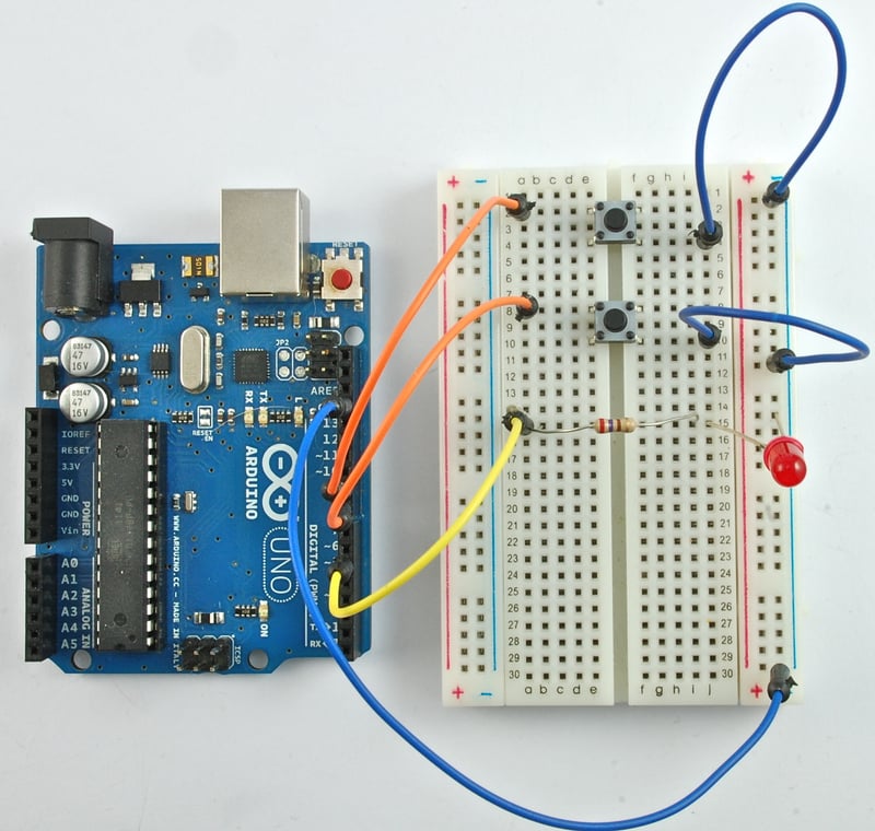
@long briar Here's a tutorial on using push buttons, from the Adafruit Learning System:
https://learn.adafruit.com/adafruit-arduino-lesson-6-digital-inputs/overview
 wet crystal
Does someone know the few lines of code I need to add to the ESP32-Cam that it turns on the led as soon it is too dark?
north kelp
@wet crystal Who makes that board? Can you link to the product?
wet crystal
Nvm the LED gets way too hot
north kelp
Perhaps you can use external LED(s) to light, based on a histogram of brightness levels.
wet crystal
Its not that important
pine bramble
Hey all! I've been running an Adafruit Feather M0 with a 5V PSU to power a LOT of LED strips for the last year. The other night, I kicked out the ground wire from the PSU going back to the arduino. I tried doing a quick fix on the fly, but I kept getting flashing of the LEDs meaning the ground wasn't right. Where to I attach the GND wire from the Arduino on the PSU? To the ground of the PSU or the negative of the LED strip on the PSU?
pine bramble
I have been attaching the GND from the Arduino to the GND on the PSU, but the random flashing (telltale ground problem) persists.
long briar
Thanks @north kelp
pine bramble
I fixed my problem! I had stepped on the Adafruit Feathe M0, bending the pin slots onto the reset button 🙂 doh!
 knotty rover
Adafruit Feather Lora M0 question: I got 2 of them up and talking today. I have a basic sketch that read some buttons, and sends a struct of their state on state change. when I press the buttons really fast though, it misses some presses. I removed all the delays from the example, and still am dropping some? any ideas? I can work on cleaning up an example to upload later tomorrow if anyone is up for helping take a look and see if anything sticks out
burnt island
LoRA is really slow so that's not to unexpected
north stream
If you really don't want to miss presses, you might have to write up code that keeps track of the presses using interrupts and then batches them up and sends them over the radio link.
odd fjord
You may want to investigate if you are missing the button presses or missing the radio messages. Different problems requiring different solutions. For missed messages, you can look at the "reliable datagram" options.
knotty rover
i'm seeing the presses on the transmit node
@north stream tracking all state changes will matter, so press release press, is different the press, and stay press. so i'd have to batch up an array of states in that instance
low latency is my main concern
i wish there was an rf24 feather, as I had everything working great on there. Lora feels like its my only fcc certified feather option for rf modules integrated in the board
I have a bluefruit le m0 feathe ras well, but i have had trouble getting bidirectional communication with it and windows hosts
north stream
Yeah, low latency with a limited bandwidth, random delay connection is ... tricky.
knotty rover
i've considered doing a polling setup, and treating it like udp
i know that will affect battery life
but worst case i just use a big battery and be spammy
less then ideal for sure . . .
part of why I came here for ideas 🙂
on the tx side if any inputs are set, spam their state till all are off again
then in idle it won't affect battery life, but if its pressed i just send updates
 tawny veldt
@knotty rover have you considered using LoRaWAN?
knotty rover
@tawny veldt I hadn't looked into it so far
 worthy thistle
Anyone here have experience running Arduino CLI on a Raspberry Pi?
 chilly valve
Looking for a bit of help with a very short-notice, quick and dirty project I'm doing with some LEDs.
Trying to figure out exactly what items I would need.
rocky igloo
@chilly valve Most likely you'll need some LEDs. Probably need some resistors too, around 1k ohm give or take, one per LED. Need more details to say more than that. 😁
chilly valve
Hah, was waiting to see if anyone was around before I text dumped.
tl;dr is I have a gas mask. I want to stick LEDs on the inside of the lenses/lens frames so they light up.
rocky igloo
Do you have something already picked out as the controller?
chilly valve
I don't easily have access to a soldering iron, is a limitation.
And no, I do not. Buying everything as one.
....bonus points if I can grab some sort of itty bitty mic so I can make the brightness sound-sensitive, but that's 100% optional.
rocky igloo
Color of LEDs? Changing or fixed?
chilly valve
Figured I need the LED strips, the controller, and any connecting wires. Plus a power sources, whatever would be good for that.
Green.
Imma make a cheapo techpriest mask.
rocky igloo
I'm an old engineer guy. I don't know what that is. 😉
chilly valve
Warhammer 40k thing, it's a sci-fi thing.
rocky igloo
OK, I know what sci-fi is.
rocky igloo
OK, whatever floats your boat my friend.
chilly valve
Hah. You get what I mean though.
I have a mask. I just need to grab some components to make the eyepieces glow.
rocky igloo
Gotcha. I'm thinking about what the options might be.
chilly valve
something plug-and-playish (discounting the need for coding, obviously) and lightweight, if possible. It is for a costume.
Figure if I can get some adhesive strips and wires I can bind everything together and go grab some scripts from somewhere
rocky igloo
I'm thinking that this Learn Guide has I lot in it that I don't know about. Maybe you could give it a scan too and see if it fills in any blanks for you. The guy who wrote it has done more of this stuff than most folks. https://learn.adafruit.com/kaleidoscope-eyes-neopixel-led-goggles-trinket-gemma

Adafruit Learning System
Fashion headwear for cyberpunks, steampunks and Daft Punks.
chilly valve
ah, that
yeah, requires soldering, so no-go.
I'll have another crack at this tomorrow. Thank you, though.
rocky igloo
Yeah, I just don't know of any strips or rings like that which don't have to be soldered. Maybe tomorrow afternoon or evening when there are more folks on here, someone will be able to help more. Good luck with it.
 narrow thorn
The way PT was talking on the "ask an engineer" show last night it sounded like Arduino Pro was not supporting any hardware except arduino.. I don't think this is the case. I see a sparkfun board listed as well as the arduino boards and there is still the boardmanager that should be able to pull in other 3rd party boards like the old "classic" version did. There is a bug that it doesn't run on windows 10, so I can't test this theory of mine.. but I really don't think they would do a HUGE 180 and shutout other boards. I think it's more of an it's an early alpha peek and they are understandably testing it on their stuff first since I would imagine that is what they have easy access to.
I mean I hope I am right.. because if that were their attitude I would have to question supporting them.
I love CircuitPython.. but there are things like FastLED that make things possible that you just can't do in CP. Adafruit_fancyled adds some of them but not all and the speed is no contest especially when you enable parallel writes in FastLED.
north stream
@chilly valve There are a few possibilities that come to mind. One is to use a Circuit Playground Express, which has the CPU, LEDs, and microphone all on one board. If there's room for that in your mask, it might be the easiest route forward.
Failing that, there are LED strips with built-in connectors like https://www.adafruit.com/product/3919 which can either plug directly into boards that have the matching connector or use adapters like https://www.adafruit.com/product/4046 with spring terminal blocks like https://www.adafruit.com/product/1074 and push-on jumper wires to connect to CPU boards with presoldered headers.
 surreal pawn
would you expect the same code to run nearly 10x faster on pygamer m4 (samd51) than on hallowing m0 (samd21) ?
odd fjord
@surreal pawn are you seeing that or asking if you would expect it.? If you are seeing that, are you running the same version of CircuitPython on both. there have been some major recent improvements in the speed of CP execution so changes may be due to more than just the clock speed difference.
surreal pawn
I'm running c++ code on both using platformio's arduino and unit testing nonsense
I'm not using floating point either
I'm working on some software audio synth stuff and timing it with micros(). to generate about 1/4 second of samples takes 157000 micros on hallowing m0 vs about 16000 on pygamer m4
odd fjord
ah -- sorry -- I have no idea ... factor of 10 sounds a bit high -- clock speed , I think went from 48 to 120 MHz but lots of other things may be contributing.
just realized this is the #help-with-arduino channel -- I should not have chimed in with CP comments. 😳
north stream
micros() may be inaccurate in some cases if there's timer/interrupt contention.
chilly valve
@north stream apologies for the delayed response, I'm squeezing things in on lunch break. Preferably, I would be able to to use extender wires with headers and such to sort of separate the components a bit. Not far, it would just be best to put the mic near the mouth of the mask, the speaker externally, the lights in the eyepieces. Also, sticking the controller and power source on the exterior. Then I can tuck them into the big robe hood or somewhere else.
north stream
Yeah, you said you'd be away, but I figured I'd put down my thoughts so you could have them whenever you were available again.
chilly valve
Much appreciated in that regard.
If absolutely necessary, I CAN get a soldering iron; I've done some before. It's just something I'm trying to avoid for the sake of speed.
I was hoping to stick to components and a controller that come with pins and headers already integrated.
north stream
There are a few controllers available with headers already assembled like https://www.adafruit.com/product/3379
Then you can use male/female extension wires like https://www.adafruit.com/product/825 and the spring connectors to hook up to the LED strip adapter.
Alternatively, as I mentioned, you can get a controller board the LEDs can plug into directly
chilly valve
Well that would work just perfectly, if I can make the wires a tad longer and stick a mic to it too.
Then it's all just finding the scripts and sorting the power source.
Probably would have to trim the LEDs and use an adhesive variant, but if I was reading correctly most of them are trimmable with wire cutters.
north stream
Yeah, the LED strips can be cut.
Many of the controller boards have a built-in power connector that matches the one on the LiPo cells that AdaFruit sells, so you can just choose one with the size and capacity that suits your project and plug it right in. The Feather boards even include built-in charging circuitry.
chilly valve
Well hell, that sounds quite perfect for my needs. Feather boards can hook up to a mic too?
I dont actually need any sound output. Just the ability to have the brightness of the LEDs spike when it detects noise.
Easy way to indicate speech when there's no moving mouth.
north stream
You might have to get a little creative for a microphone, but some boards support this PDM microphone https://www.adafruit.com/product/4346
chilly valve
....hahaha. I just tried reading that and the sheer technical density just sent my eyes spinning in different directions
north stream
Yeah, a simple MEMS or electret microphone would probably do, but then you need to deal with bias, amplification, etc (most of the breakout boards I've seen require soldering)
chilly valve
Oh lordy.
north stream
You have one of those pesky multiple interacting requirements type of projects.
chilly valve
Unfortunately, yes. And not a lot of time to puzzle it out.
north stream
What are your feelings on sewing with conductive thread?
chilly valve
.....I could make it work.
Though if I manage to stab AND shock myself at the same time I would not be surprised.
I have the grace of a hippo on roller skates.
north stream
I figured if you were building a costume, that might be an option.
north stream
You could then use the Circuit Playground Express, which takes care of the power, CPU, and microphone, then attach it to https://www.adafruit.com/product/2566 with conductive thread, banana plugs, or alligator clips, then plug the LED strip into that.
chilly valve
Biggest issue with that is that the mic cant just be built into the circuit board due to mask constraints.
It's an honest to god military surplus gas mask. There is very little room between the mask and my face.
....huh
Apparently swears of any type are bad. Deleted my message.
north stream
It should duct sound around pretty well. You might be able to hide the CPX in one of the filter canister holders (it's round, it might fit) or tuck it off to one side or along your neck.
Yes, this Discord is open to all ages, so we try to keep it family friendly here.
chilly valve
I was just apologizing for being picky, and saying I appreciate all the help.
north stream
Alternatively, you could opt for the Grove ecosystem, which includes all sorts of plug-together sensors like http://wiki.seeedstudio.com/Grove-Sound_Sensor/
chilly valve
Aaaargh, I wish I wasnt on my phone
Would be so much easier to compare back and forth
north stream
Oh yeah, doing research on a phone can be truly frustrating.
chilly valve
On the plus side, it's my day off from after work streaming, so I can dig into this and get a part list together after work
Only 4 more hours, weee
So I have some options, excellent. If all goes well, I can have a part list picked out and ordered tonight.
north stream
It turns out that there is a ready-made Grove adapter available https://www.adafruit.com/product/4309
chilly valve
Huh. So get a particle feather board, one of these, two LED strips, and a grove mic? Plus the cables to connect the stuff.
And whatever adafruit power source fits the feather board, right.
north stream
Sounds about right.
chilly valve
Excellent.
Hope you'll be around in a few hours. It would be much appreciated to run a parts list by you before I click purchase.
safe shell
Does Adafruit have pins_arduino.h hiding somewhere for the ESP32 boards? I can't find it at https://github.com/adafruit/Adafruit_Arduino_Boards/tree/master/variants or https://github.com/espressif/arduino-esp32/tree/master/variants

GitHub
Configuration and other support files to use Adafruit's boards like Trinket, Pro Trinket, Gemma, Flora, and more with the Arduino IDE 1.6.x - adafruit/Adafruit_Arduino_Boards

GitHub
Arduino core for the ESP32. Contribute to espressif/arduino-esp32 development by creating an account on GitHub.
found it (Feather) https://github.com/espressif/arduino-esp32/blob/master/variants/feather_esp32/pins_arduino.h (I was looking for "A"dafruit like in the board manager) Huzzah Breakout is slightly different, can work around that
GitHub
Arduino core for the ESP32. Contribute to espressif/arduino-esp32 development by creating an account on GitHub.
chilly valve
@north stream picking out parts now. Could appreciate some final assistance, if you're around.
north stream
Was watching a movie 🎥
chilly valve
olo
was looking at these for the LEDs https://www.adafruit.com/product/2241
Move over NeoPixels, there's a new LED strip in town! These fancy new DotStar LED strips are a great upgrade for people who have loved and used NeoPixel strips for a few years but want ...
unless I can get away with cheaper ones, I unno
@north stream https://www.adafruit.com/product/3995 combined with the grove shield you linked

Woohoo, it's time for a Particle Mesh party! And the Particle Xenon Kit is the most basic element (ha!) for your mesh network. The Xenon is a low-cost mesh-enabled development kit that ...
north stream
Those are the "Dotstar" (4 pin) ones, as opposed to "NeoPixel (3 pin) ones like https://www.adafruit.com/product/3919
chilly valve
Hm, I see
change to the neopixel version then
grabbed a 1200 mAh 3.7V battery with the Particle kit
and then I believe you suggested this? https://www.seeedstudio.com/Grove-Sound-Sensor.html
north stream
Yeah, solderless options for microphones are thin on the ground.
chilly valve
that looks like it'd work though. Not like you need quality for it.
just the ability to sense volume.
does it just detect sound, or can it detect decibel levels?
north stream
It just detects sound, you'd have to do a little postprocessing to detect envelope, decibels, etc.
chilly valve
that's scripting though, not hardware
north stream
Yeah, at that point it's a software problem
chilly valve
that's dealable with
So there's nothing I'm missing from my list then....besides making sure I have the right cords?
controller works?
north stream
You'll need to figure out a way to lash the LED strip to it. I'm not sure what you mean by "controller works"
chilly valve
there's nothing wrong with my selection, I mean
Just need to figure out connecting the LED strip to the controller, I think.
north stream
Aside from I don't know if you have the parts you'll need to hook up the LED strip
chilly valve
grove mic just needs a compatible cord to hook to the shield
so that's one thing
lemme look
north stream
Yeah, ordinary Grove cable will work for that (Seeedstudio should have them)
chilly valve
So, looking at this
grove shield apparently works with stemma cords
Adafruit Industries, Unique & fun DIY electronics and kits : - Tools Gift Certificates Arduino Cables Sensors LEDs Books Breakout Boards Power EL Wire/Tape/Panel Components & Parts LCDs & Displays Wearables Prototyping Raspberry Pi Wireless Young Engineers 3D printing NeoPix...
apparently there's a bunch of converter cables.
example: specifies grove. https://www.adafruit.com/product/3955

This cable will let you turn a JST PH 4-pin cable port into 4 individual wires with high-quality 0.1" male header plugs on the end. We're carrying these to match up with any of our ...
north stream
It would be cool if there were a JST-PH to JST-SM cable and if the Grove connectors had a pinout compatible with the DotStar strips.
chilly valve
do they not?
north stream
However the cable you linked, plus some short male-to-male, plus the spring terminal blocks, plus a JST SM receptacle will get you there, and let you adjust the pinout as needed.
Oh, that's a male header cable so you don't need the male-to-male bits, just the spring terminal blocks https://www.adafruit.com/product/866 and the 3-pin JST SM receptacle https://www.adafruit.com/product/1663 should get you there
I don't know if the Grove connectors have a compatible pinout for DotStars or not.
chilly valve
I'll have a look.
north stream
Might want to try to find a way to run 3.7V from the LiPo to the LEDs (3.3V is a bit low, and the on-board regulator providing the 3.3V would probably be overloaded if trying to power the LEDs)
Looks like the Grove adapter has an extra row of contacts outside the Feather ones, so you'd just need to plug a wire in to the Vbat pin and run it to the +V lead of the LEDs.
chilly valve
gah, so many parts
undone oracle
@mild elk i think its about time i order a RTC DS3231. I think my DS1302 is giving me problems
mild elk
Good, it's a great RTC. You can also try my library
north stream
@chilly valve Yeah, it's a lot of parts, mostly to avoid soldering. 🤷
@undone oracle Note that a lot of the "DS3231" parts out there are are counterfeit and will give problems, make sure to get one from a trusted vendor.
mild elk
My DS3231s seem legit...
mild elk
I need more than two decimal places when calculating roots of numbers
Is it possible to do that?
north stream
I believe the "float" type in Arduino has around 6 decimal digits of precision: perhaps the results have the precision you want, but the method you're using to print them is truncating?
knotty rover
i have two feather m0's with lora, sending a string back and forth, I think i'm seeing a little endian issues because I send 1|0|0|0 and receive 0|0|0|1. what is the right way to solve this?
mild elk
@north stream i'm using a double data type, and computing roots with pow(number1, 1/number2)
north stream
In Arduino (except Due), doubles are the same as floats. Can you give an example?
mild elk
I can even give the entire code
north stream
I'm guessing either I'm misunderstanding what you're saying, precision is getting lost in printout, or you're hitting cases where precision is lost due to scaling in the calculation. Just trying to narrow down what's going on.
mild elk
Alright, I'm manually inputing numbers that are saved as double data type. Then, I calculate the root with pow(number1, 1/number2) and printing it over serial
Alright, I got it
I need to use Serial.println(number, 6)
Now I need to think of something that knows how many decimal places are needed to display the result
north stream
Not sure what you mean there, are you looking for a known-width printout or something?
Or are you expecting numbers like 123.456 as well as 0.000000078?
undone oracle
@north stream @mild elk do either of you guys have an amazon link to a ds3231?
mild elk
@north stream I mean that if the result is for example 2.2, I'd like to display 2.2 and not 2.200000
mild elk
@undone oracle no, sorry, I don't have one :(
chilly valve
@north stream right, I've got a bit more time to look this over. Grove mic cable determined, looking at trying to figure out the exact set of cables for the battery and the the LED connections.
undone oracle
@mild elk where did u buy ur ds3231 from?
mild elk
From my local electronics shop
undone oracle
Oh. I don't think anyone near me has ds3231
north stream
I wouldn't recommend buying DS3231 from amazon, they have a lot of sketchy merchandise.
@mild elk Ah, you want trailing zero blanking. That's trickier than it looks because roundoff error means you'll often get 2.199999 or 2.200001 instead of 2.2 so you'll need to decide whether those cases are important to you and what you wish to happen. For the simple 2.20000 case, you can convert it to a string and then just have a loop that checks if the last character is a zero and if so, removes it. For the other cases, you'd need to do some comparisons/rounding and decision making.
@chilly valve The battery connection is pretty easy, the cells AdaFruit sells already have JST connectors on them that mate with the one on the Particle board.
chilly valve
Didnt you say I should try to make it go to the LEDs though?
That the 3.3V the particle board puts out arent enough
north stream
Yeah, I think your best bet for running the battery connection to the LED is to use a jumper wire from the Vbat pin on the Grove adapter to a spring connector to the power lead to the LED strip.
mild elk
I do care about these cases (1.999999 etc), but I'm not sure if I can convert it to string because later I want to display it on display and I don't know if I can write a string to for example PORTB
north stream
That's two different things: you may need to convert it to a string and then modify it for display, and keep the numeric value as well for use internally for controlling things.
chilly valve
Okay....so grove adapter, as in the shield, yes?
Gah, I need like a diagram or something to keep this all straight
north stream
  float root;
  char rootbuf[10];

  root = pow(n1, 1/n2);
  dtostrf(root, 9, 5, rootbuf);

  // now you have your value in "root" and your string in "rootbuf"

  while (rootbuf[strlen(rootbuf) - 1] == '0') {
    // last character is a zero, discard it
    rootbuf[strlen(rootbuf) - 1] = '\0';
  }
Yes, pictures are a great thing for builds like this.
I can doodle one out, but you'd probably get more value out of drawing it yourself.
mild elk
Alright, but I want to display rootbuf, do I convert it back to double or what?
north stream
Don't need to, Serial.print() supports strings so ```c
Serial.print(rootbuf);
Ok, but if I had for example SPI 7 segment display
north stream
The only reason for converting it to a string is to clean it up for display, so converting it back to double makes it pointless.
Ah, for a 7 segment display, you'd have two choices, either use the string and map characters to segments, or mathematically convert it a digit at a time, and convert the digits (and decimal point location) to segments (and have some other logic to blank trailing zeros).
mild elk
Wait, I can read rootbuf one character at a time, right? Then I could create a loop that reads a character, converts it, send it and deletes from rootbuf
And something for decimal point as well
Does that make sense?
north stream
Yeah, that's the first option I described.
mild elk
Ok, good
Thanks!
 dense kiln
How does the arduino uno connect to computers via USB? I want to connect a stand alone atmega via usb, without ftdi breakout boards, but I'm not sure how
solar sail
It uses one of the USB atmegas (atmega16u2)
dense kiln
Thanks a lot
north stream
The 32U4 is a popular USB-capable standalone AVR mega.
dense kiln
My aim is not to use that mcu but a more powerful one, but thanks for the suggestion
I'll have to research about how to use the 16u2
rocky igloo
@dense kiln The ATmega 16u2 is a less expensive lower spec chip compared to the 32u4; same family but 16k of flash instead of 32k, 512 bytes of RAM instead of 2.5k. Maybe not what you're looking for to get something more powerful...
What about a SAMD21? They're the same price and worlds away for features.
dense kiln
Oh I didn't explain myself properly. My project will consist of an ATmega2560, standalone, and some other thing, probably the 16u2 to be used for programming via USB
Sorry
north stream
I wonder if there's a nice ATmega2650 class chip with built-in USB.
surreal pawn
yeah it was in the teensy 2
wait that's the 32u4 that's in the leonardo
bigger would be AT90USB1286 or AT90USB1287
chilly valve
@north stream I have a rough diagram. I'm just trying to understand the last cable setup.
north stream
Ah, okay. The one to the LED strip?
chilly valve
Yup. I'm looking specifically to nail down EXACTLY what I need.
So the battery that comes with the xenon gets plugged directly into it. Got that.
The grove shield goes on top of the xenon.
the mic uses one of the grove-compatible cable to connect to the grove shield.
So the only mystery to me is A) which of the LED strips am I using, and B) how do I hook them to both the battery and the xenon.
You mentioned the VPin and a spring connector and the like, but that's a tad confusing.
I've been looking for the vpin on the grove shield pictures, but I can't determine which is it.
north stream
The Xenon pinout is here (it's compatible with the Feather standard): https://docs.particle.io/assets/images/xenon/xenon-pinout-v1.0.pdf
The power pins are on this end
You'll want the ground pin (fourth one down on the long row) and the LiPo+ pin (top one on the short row)
The connector I mentioned is this one https://www.adafruit.com/product/866 which will let you connect wires without having to solder them

These are like the fancy electronics equivalent of the wire nuts electricians use to bind wires together. They are a lot easier to use as well! Each block connector has a metal block inside ...
You can use either the NeoPixel or DotStar LED strips, you'd just need the right connector. One workable choice is this one https://www.adafruit.com/product/3919

Plug in and glow, this Adafruit NeoPixel LED Strip with JST PH Connector has 30 total LEDs in a "60 LED per meter" spacing, and is 0.5 meters long, in classy Adafruit Black. Its ...
For that strip, you can use this connector to plug into it, then the other ends of the wires go to the wire connectors. https://www.adafruit.com/product/4046

This cable will let you turn a JST PH 3-pin cable socket into 3 individual tinned wires. These are great to match up with our JST 3-PH cables, for extending and connecting sensors or LEDs, ...
The only thing left is wires to go from the Grove adapter to the wire connectors. If you already have some solid core wire, you can use that. Otherwise you can use these https://www.adafruit.com/product/759

Handy for making wire harnesses or jumpering between headers on PCB's. These premium jumper wires are 3" (75mm) long and come in a 'strip' of 40 (4 pieces of each of ten rainbow colors). ...
 vestal nebula
Hey everyone, so I’ve been meaning to make a diy game pad and came across the adafruit video on how to do so. Then I checked, and the blue fruit ez key was discontinued but the equipment is the blue fruit LE module. Can I still use similar steps just with a different module? Thanks guys
chilly valve
@north stream So basically, I am using two spring connectors so I can link each LED strip to both the lipo pin and the ground pin, yes?
I then have two questions: what do I do with the third wire, and what's this about the grove adapter going to the wire connectors?
north stream
Right with the spring connectors.
The third wire will go to one of the unused data pins on the Xenon (choose a pin that can support the NeoPixel format)
The Grove adapter has a double row connector on each side of the Xenon. I'm guessing that the pairs of holes are connected in parallel, so if you put a wire in next to a Xenon pin, it will be connected to that pin.
chilly valve
we are talking about the shield, correct?
north stream
Yeah, the board the Xenon plugs into.
chilly valve
Okay, oooookay
I see what you're talking about now. I get it.
Right, so the spring jumpers go into....the grove ports?
but those are 3.3V....
hm.
north stream
You'll need some wires to go from the plugs in the Grove adapter to the spring connectors.
chilly valve
Ooooooooooooooh.
I get it. Okay.
Right so it goes LED plug => plug to 3 wire adapter => Spring connector
And how do the spring connectors connect to things? Do they slide over pins, or can you clamp wires on the other end?
do spring connectors combine the wires into one output here?
north stream
They just accept wires. So you'll have one wire going from the Grove adaptor receptacle to the connector, and one wire from the JST adapter to the connector
chilly valve
ahhhhhh, I see. So they just link things.
So I have...three spring adapters.
One in which I stick each of the power wires, with the third slot going to the parallel port for the lip power
since you said to bypass the 3.3V, and that's what it looks like the grove adapters can only put out if I'm reading the text on them right.
Or would I say screw it and use the grove adapters anyways?
north stream
I'm not quite sure what you're asking. Here's how I envision the LED strip wiring. The orange boxes are the connector blocks. The three wires coming from the right side are the JST adapter the LED strip plugs in to.
Where it says "Grove goes here", it should say "Xenon goes here", oops
chilly valve
Hm....I see.
That looks like it's only for one LED strip though.
would I be somehow linking the two strips, or would I choose different ports?
Or wait, the spring connectors have three slots
would I just double up the input wires?
And then I can just slot the mic into one of the unused grove ports.
chilly valve
@north stream if what I'm saying is correct, please confirm. Because then that's it, I know what I need to buy.
I mean, assuming I can run two LED strips off of one pin.
power-wise.
north stream
The power and the data are two different things.
The power in the diagram I showed is coming directly from the battery, the two strips should be able to share that.
chilly valve
Oh, right. Okay. so the power and grounds can be doubled up, but I'd need a fourth spring connector to connect it to a new data pin, yes?
north stream
What to do with the signal depends on whether you want the two strips to do identical things.
chilly valve
Also oh yes
they are supposed to be identical
I'm just using two strips because there's two eyepieces.
north stream
Then you should be able to drive both of their data in pins with the same data out pin from the controller. However, you'll need a second strip and a second adapter.
chilly valve
by strip, you mean LED strip.
north stream
Yes.
chilly valve
Just being absolutely certain, apologies.
Then yeah, I get it. I just double up the wires in the connectors.
.....absolutely brilliant. Sorry it took about three days for me to get my head around it.
north stream
It is a little going around the block to get next door, due to what's available that doesn't need soldering.
chilly valve
Hah, that's fair.
When I have more time and funds to get myself a decent soldering iron and more projects, I'll probably indulge that then.
north stream
Yeah, you suddenly get a lot more options at that point (including being able to use bits of LED strips you cut off for other projects)
chilly valve
Right right, I gotcha.
north stream
When I was designing a project for children, I made sure to build it in a way that didn't require soldering, so it's all clip leads and tape. However, I didn't think clip leads would work reliably inside a mask that's being pulled over your head and moving around.
chilly valve
Oh, just out of curiosity: if I wanted to go with a dotstar strip, I'd just increase the number of connectors by one? Use two data pins instead of one?
Also yes, absolutely not. I'm going to be using wires to keep as much of the parts external as possible, frankly.
north stream
Right. The DotStars take two signals (clock and data). There are a couple of special pins with hardware support for them, but you don't even have to use those (they're handy when you're controlling large numbers of LEDs and need maximum update speed).
chilly valve
Gotcha.
Well, that's really a question of a different fish
Which density of LEDs would be best to make the general eyepieces glow
Figured more dense might be more effective.
north stream
Depends on the effect you're going for. You can get more light with better consistency and finer control with denser LEDs. Side emitting strips might be good too, depending on how you plan to mount them.
The strip I suggested was mostly because it was short (you don't need a lot of length for eyepieces), already had a connector (no soldering required), and fairly inexpensive (you did remark that one of the other strips you were looking at was costly).
I did find some ridiculously high density strips overseas but shipping alone was $50
chilly valve
Oh lordy, no
And well, you how they use pulsing lights in entertainment to denote speech in robots and AI?
That's the effect I'm going for
I'll probably wear like a thin blindfold to make sure my eyes aren't visible inside the mask
north stream
I was wondering if you were going for solid color effects like that, which might be doable with just a few emitters and some light guides.
And yes, these LEDs can be very bright, eye protection is a good idea!
There are even LED rings that can make it really quick to have lights around your eyes, but as far as I know, they all require soldering https://learn.adafruit.com/kaleidoscope-eyes-neopixel-led-goggles-trinket-gemma
Adafruit Learning System
Fashion headwear for cyberpunks, steampunks and Daft Punks.
mild elk
Is it possible to run an Arduino on 16,384MHz crystal? Are there going to be any problems?
chilly valve
Wish I could use the rings, but the eyepieces are irregular shaped.
and SIGNIFICANTLY larger.
Uh
quick question
was looking at the grove sound sensor on amazon
lists its operating voltage at 4V - 12V
is that gonna be an issue?
north stream
Huh, I'm not sure. It says it works with things like Beaglebone and I think those are 3.3V?
The manual says "Vcc of the Grove interface is normally 3.3V" https://www.mouser.com/catalog/specsheets/Seeed_101020023.pdf
north stream
The spec sheet on Seeed also says 4-12V, but I'm not sure where they get that, since it's supposed to be Grove compatible.
chilly valve
Parts have been ordered.
I'll have them come the weekdays.
we'll just have to see, ey?
Now to go find C++ scripts
rocky igloo
@mild elk Assuming that's a Euro-style comma (not 16+ GHz!) the ATmega328p is spec'd to run up to 20 MHz so no problem there. Arduinos actually underclock the chip. You should probably look in the configuration files for the clock frequency constant definition, and some libraries might break anyway because people take shortcuts. But you ought to be able to make it work. It's only a 2% difference, right?
 dense ridge
Hello, I have a small issue with my feather m0. It seems like it hangs in the bootloader every time I upload a program. Any thoughts on what might be causing this?
Also, would this be better to take to the customer support forums?
 candid island
New guy here. Anyone willing to help a newb out with what seems like an easy project? I appreciate it and look forward to learning more. Thanks all!
north stream
You're better off asking a specific question, as different people have different fields of knowledge.
 void vortex
Hello , i was working on a project with heltec esp32 lora development board but i am stuck in something
I wanted to interface neo 6M gps module with this board and read the $GLL string ,pars it and send the data over lora network
Mainly the longitude and latitude
north stream
Seems fairly straightforward. You could parse the string with strtok() or somesuch, extract the fields you want, then send either the resulting strings or convert them with atof() and send the values.
candid island
Makes sense...
I have a nano and an a4988 driver, the capacitor I need and some switches. I wanted to build it so that buttonA will spin the motor at a speed for x rotations or steps or whatever. Then I want the other switch to do the same thing in the other direction. Thanks all.
candid island
Okay, so I am to a point where my code compiles and everything just fine. The switches move the stepper motor at the speed I have set, but they both move it the same way. Having issues with the dirPin high/low in my sketch. I'm using if statements for each of the switch and it seems to be working fine and compiling fine like I mentioned just both switches do the same thing.
Thanks
 random oyster
@candid island it looks like AccelStepper takes care of setting the direction based on the speed you give it. positive speed is one direction, negative speed is the other direction. so you'll want to change the speed to change direction.
pine bramble
Whats up folks! I'm having an issue trying the StrandtestBLE example for my adafruit feather m0 in the IDE. When I try to verify it, it says "BLEPeripheral.h" no such file or directory
Ah, installed the library, problem solved. Does anyone know offhand what modifications need to be made to StrandtestBLE to use RGBW LED strips? I know you replace NEO_GRB with NEO_RGBW in one of the first lines of code, do I need to make other changes (like adding a fourth integer to all lines containing RGB to make it RGBW) ?
Whenever I upload the code, the serial monitor says ⸮⸮
pine bramble
Well, fixed that by switching up the baud. Still no proper colors on my LED strip or any response from Bluefruit app. Halp 😄
mild elk
Seems like the Arduino will work with 16.384MHz crystal with no issues.
north stream
@pine bramble Try using NEO_RGBW and see if it compiles?
@mild elk Yeah, the chip is rated to 20MHz (at 5V). However, timing might be slightly different (there's an F_CPU #define you can change if you're using things like delay() or millis() and you want them to be accurate)
pine bramble
@north stream I did, it compiles, but in the comments at the top it says I need to add suppport for the NRF52 based boards. When I install that, it now says "Error: No Valid JTAG interface configured." when compiling
@north stream err when uploading. It compiles fine.
Weird, its set to be an arduino zero, I didn't do that.
north stream
I was going to ask if you had the board and programmer configured right. That is weird, but should be an easy fix.
pine bramble
Hmm. When I go to upload the code, it freezes and changes from an Arduino Feather M0 to Arduino Zero... scratches head
and (Programming Port)
pine bramble
What's most annoying is that I have to restart my computer every time I try uploading this sketch, as my board isn't recognized after.
north stream
I wonder if those two issues are related. They're both a little out of the ordinary.
pine bramble
Hmm. Now my IDE won't recognize my board at all. 😦
There's a red light on the feather m0 next to the USB power which isn't usually on. I tried pressing reset but got nothing. Now I just want to get back to what I had instead of bluetooth lol darn
Hmmm.... my feather is not showing up in Ports in the IDE on my laptop either. The windows explorer window opens when I connect it to PC, but that's about it. I wonder how this can be solved.
Gonna try device recovery
Nope, that didn't work. Still not showing up under ports. Very confusing, as it's been working all morning.
 proven mauve
I am having a devil of a time with a 328p chip
I have a program running on two chips, one with internal 8mhz, one with external 16mhz crystal. Same program, but the 8mhz runs it too slow, at about 2/3 speed.
So...
On the breadboard, both chips work great, except the speed difference
I've tried moving it to a proto board 3 times over the last 3 days and each time I get no working 16mhz setup
So on the 3rd attempt I've broken it down to steps... connected only the oled... works with the 8mhz chip
connected the crystal, 8mhz still works, 16mhz wont
it uses short wires to connect the chip to the crystal pins, to 20pf cap pins, and from the cap pins to ground
unfortunately this extended project has almost run me out of wire so my colors are all jacked up atm.. ground is blue to gray to the yellow between the oranges
mild elk
I don't see a reset pullup resistor anywhere on that board
And I see no decoupling caps as well
proven mauve
I added a 100nf decoupling cap after that pic
mild elk
But the chip has two vcc pins
From my experience it's the best to buy small smd caps and solder them directly across the pins
proven mauve
Gotcha. I just can't figure out why it will consistently work in a breadboard but as soon as I start soldering, no dic
*dice
but the 8mhz chip works just fine
mild elk
Maybe your crystal is faulty
Or you connected it to wrong pins
Triple check the connections, even with multimeter
candid island
@random oyster thank you for pointing that out, I had forgotten about that. Had a little trouble making a negative value so what I did was create another AccelStepper up top called Xaxis with the same pins and in setup set Xaxis max speed to a negative value and was good to go! Thanks all!
 inland anvil
I've got a strip of 144LED/Meter all white dotstars and I'd like to be able to turn them on and off using a momentary switch. I understand that you can simply wire in a switch to cut power but there might be some lag time when it starts back up due to processor lag. I was told that I can wire in a switch to any GPIO on my Metro Mini and use the colorWipe function and assign it to the button.
I have no idea how to do this on my sketch. All I'm doing is adding this feature to the standard "strand test". If anyone can help, I'd greatly appreciate it! Thanks!
 potent ferry
hello guys. I need help please. I am trying to run on an arduino 2 accelerometers to control 1/2 of the rotation of 1 servomotor, and 2 pressure sensors to control the other 1/2 of rotation of the same servomotor. I am using this line of arduino
else if (y1_axis > -95 && y1_axis < 20 && y2_axis > -90 && y2_axis < 20 && sensorBL < 10 && sensorBR < 10) //flat dead end no servo movement - center position
{
servo1.write(90 , 100, true); //center speed = 0-255
}
else if ((y1_axis < 80 y1_axis > 75) && (y2_axis < 80 y2_axis > 75))
{
servo1.write(80 , 25, true);
delay(100);
}
Serial.println("y1: " + String(y1_axis) + " y2: " + String(y2_axis) + " L: " + String(sensorBL) + " R: " + String(sensorBR) + " SPeed: " + String(speed)+" agnle: "+String(angle));
delay(100);
}
The problem I am facing is that when I move accelerometer #1 of a certain angle, the motor rotates from the center (original position) to an angle (final position) ; and then the motor rotates back to the center when I bring back the accelerometer # 1 to its original position.
that is fine, but I am using 2 accelerometers and I would like that the accelerometer #2 would work at the same time of acelerometer #1, so that if I move accelerometer #2 from its center (original position) to an angle (final position) , while accelerometer #1 is going from its final position - back to the center (original position) , the servomotor remains in the position of the final angle. Practically, I want the accelerometer #1 and #2 controlling at the same time the motor. Right now it seems that for accelerometer #2 to control the servomotor, accelerometer #1 has to finish the whole motion from center to the angle and from the angle back to the center.
Can you please tell me a line of coding that could fix this ? Thnaks
rocky igloo
@inland anvil Take a look at the Button sketch in File/Examples/02.Digital. It shows how to configure a GPIO as input and read the status of a switch. Where the example turns an LED on or off, use your code to change the state of the strip to all on or all off.
mild elk
I wrote a simple code that creates a rainbow animation on a Nopixel LED. It works, but the Neopixel randomly blinks. Any ideas why is that?
inland anvil
@rocky igloo thank you for this! so you're saying I could simply modify that example code, then copy and paste into the strand test sketch?
rocky igloo
Modify it, or strip out a line here and a line there and blend it with your code--whatever suits you the best.
inland anvil
@rocky igloo I'd like to keep the animation that is in the strand test the way it is and simply have that momentary pushbutton telling when to start the loop and when to cut it off...hope that clarifies what I'm going for
forgive me if any of my questions sound stupid but I'm a complete newbie to Arduino and trying to figure this all out.
rocky igloo
There are some declarations at the top of the file, some initialization in setup(), and then a test of the input in loop(). I think that if you look at it for a couple of minutes you'll get the gist of it, and then you can incorporate the switch test into your program.
Ask if you have questions. Sounds like it might be a good learning opportunity. This isn't hard.
inland anvil
ok cool. so the colorWipe thing isn't even necessary? Must be simpler than that, right? lol
just taking that button sketch and incorporating it into the strand test in the right places...that's what I'm getting from this
rocky igloo
@mild elk Just how random is it? Figuring that out might go a long way toward fixing the problem. If you make a small change in your code, like the rate of the animation, does that affect how often the blinks happen?
mild elk
Blink always occurs when I start decreasing value of any color
This is done with for loops
Color value is changed every 10ms
@rocky igloo
rocky igloo
I'd start by checking my math in that situation, maybe go really slow and print the current color to Serial each time it changes. It's easy to have a loop variable that's off by one and then white wraps around to black, or something like that.
mild elk
Maybe it wraps to -1 or something like that
rocky igloo
Yeah, if it's happening regularly. That kind of bug is really common.
mild elk
Nope, still does the same
rocky igloo
@inland anvil Use colorWipe if you want the wiping animation to happen. If don't want it to animate, you can just call setPixelColor() for each neoPixel and then show() to update the strip.
@mild elk What did you change?
mild elk
I changed for loops to check if color value is greater than 1 instead of 0
@rocky igloo
I can post my code, it's really short
rocky igloo
@mild elk If the blink happens when you start to decrease the value of any color, shouldn't you be looking at the other test--the one where you check if the color is 255 or 256 or whatever?
Yeah, go ahead. I'll take a look.
mild elk
Adafruit_NeoPixel pixels(1, 6, NEO_GRB + NEO_KHZ800);

void setup() {
  pixels.begin();
  pixels.clear();
  pixels.setBrightness(50);
}

void loop() {
  for(int red=0; red<255; red++) {
    pixels.setPixelColor(0, pixels.Color(red, 0, 255));
    pixels.show();
    delay(10);
  }
  for(int blue=255; blue>0; blue--) {
    pixels.setPixelColor(0, pixels.Color(255, 0, blue));
    pixels.show();
    delay(10);
  }
  for(int green=0; green<255; green++) {
    pixels.setPixelColor(0, pixels.Color(255, green, 0));
    pixels.show();
    delay(10);
  }
  for(int red=255; red>0; red--) {
    pixels.setPixelColor(0, pixels.Color(red, 255, 0));
    pixels.show();
    delay(10);
  }
  for(int blue=0; blue<255; blue++) {
    pixels.setPixelColor(0, pixels.Color(0, 255, blue));
    pixels.show();
    delay(10);
  }
  for(int green=255; green>0; green--) {
    pixels.setPixelColor(0, pixels.Color(0, green, 255));
    pixels.show();
    delay(10);
  }
}```@rocky igloo
inland anvil
@rocky igloo I just want to make the strip start running through the strandtest loop when i keep the button pressed and then turn it off when button is released
rocky igloo
@inland anvil. OK. The only tricky thing is that putting the button test in loop() wouldn't stop in the middle of the animation. Testing the button has to happen in the colorWipe() function, but that's easy enough to do.
Are you using any of the other demos in strandtest or just colorWipe?
@mild elk That looks right to me. I modified it to run with GCC on my PC and the transitions look right. Eg: fc 00 ff fd 00 ff fe 00 ff ff 00 ff ff 00 fe ff 00 fd ff 00 fc
What else could it be?
mild elk
@rocky igloo honestly I have no idea, that's why I'm asking
rocky igloo
@mild elk Thinking out loud... 🤔
@inland anvil I think so, although I'm trying to be sure about exactly what you want it to do.
Do you want the strip to go all black when you release the button, or do you just want to pause the stripTest animation?
inland anvil
i want to start with the strip off with nothing showing then push a momentary switch/button and have the strand test start looping through while the button/switch is pressed. The strip will cut off when the momentary switch is released.
rocky igloo
@inland anvil When the button is pressed again, do we start over from the beginning or pick up where we left off?
Even before writing anything, starting over from the beginning is probably much simpler to do.
inland anvil
Definitely for sure
simple is better for me 😉
@rocky igloo so yes a start over is just fine
rocky igloo
@inland anvil Looks like a lot of it can be stolen from the NeoPixel buttoncycler sketch. I hadn't looked at that one before.
inland anvil
Oh? So you’re saying to incorporate pieces of that sketch with the strand test? Where can I find the button cycler?
rocky igloo
@inland anvil Yes, steal a line here and a line there. It's in File/Examples/Adafruit NeoPixel.
inland anvil
I'm in the Library Manager and there are several Adafruit Neopixel libraries
rocky igloo
@mild elk How hard would it be to do what I suggested before, make the delay bigger and print the color value to Serial each time? Knowing what color you're trying to display when it blinks would really help.
@inland anvil. Lucky you! I only have one.😁
Do any of them have a buttoncycler example?
inland anvil
I"m checking right now lol...trying to figure out which one...
Will probably install several ones
If I search for Neopixel in the libraries manager, there's loads of them
Trying to read the descriptions but haven't found a button cycler example yet
rocky igloo
Things have gotten complicated with bundles, libraries that include other libraries, etc. Apparently you have NeoPixel installed a few times.
inland anvil
here's what I see
rocky igloo
I didn't look in the libraries manager, just Files/Examples/Adafruit NeoPixel in the menu bar. Even if you have more than one Adafruit NeoPixel it should just take a few seconds to look in each one.
inland anvil
aha found it!
I actually had to find it in the libraries manager and install it...wasn't installed until now
so, yes I do see the buttoncycler
rocky igloo
OK, where are you so far? Do you have a sketch open that you've started working on?
inland anvil
I've got button cycler open yes
mild elk
@rocky igloo i can do that, but I'll do it tomorrow since it's really late today
inland anvil
trying to figure out the difference between button pin and pixel pin
rocky igloo
@mild elk OK, cool. Sorry I couldn't be more help. I'm sure you'll get it.
inland anvil
right now I've got two separate pins going into my metro mini...one for clock and one for data
mild elk
@rocky igloo no, that's fine. I'll ping you tomorrow to let you know how it's going
inland anvil
and I have no idea what a pulp resistor is...is this a component I need to buy or just a way of wiring things?
*pull-up
rocky igloo
@inland anvil The comment is misleading there. You can use a pull-up resistor along with a button to control what happens when the button isn't pressed, but you don't have to in this case.
inland anvil
oh ok cool
rocky igloo
The effect of the line that says pinMode(BUTTON_PIN, INPUT_PULLUP); is that the Arduino does that for you. The "resistor" (which isn't really a resistor) is inside the chip. Like I said, the comment is confusing. It shouldn't have mentioned a resistor at all.
inland anvil
gotcha ok good to know
I'm confused here:
#define BUTTON_PIN 2 // I understand this is where the digital input for one side of the button goes...other side goes to GND
#define PIXEL_PIN 5 // Digital IO pin connected to the NeoPixels. This is what I don't understand because there needs to be 2 pins. One for Clock and the other for Data
#define PIXEL_COUNT 144 // Number of NeoPixels (mine is a 144/meter strip...I'm assuming this is correct here)
rocky igloo
Lemme see about the pixel_pin definition. The others look ok.
inland anvil
ok
rocky igloo
Wanted to double-check just to be sure but yes, NeoPixels only use one pin. Clock, data, all the same thing. https://learn.adafruit.com/adafruit-neopixel-uberguide/basic-connections

Adafruit Learning System
Everything you always wanted to know about Adafruit NeoPixels but were afraid to ask
rocky igloo
Is it possible that you have a DotStar strip?
inland anvil
Yes, sorry thought I mentioned that in my original question
rocky igloo
OMG I missed that.
Yes I just scrolled back and you did say that. Sorry!
Explains why you didn't have the NeoPixel library installed...
inland anvil
hoping this will simplify things?
rocky igloo
Probably not much different really, not a big thing.
inland anvil
seems like there's a bunch of unnecessary stuff that I can delete then?
rocky igloo
The DotStar strandtest is way simpler.
inland anvil
like the rainbow cycle, marquee pattern etc
yes strand test all the way! So that means then I should just go back to incorporating pieces of the button sketch with the strand test?
rocky igloo
Yes, decide which pin you're going to put the button on, put in the #define BUTTON_PIN statement like you did above, intialize the button in setup() by copying over the pinMode statement, ... For starters.
That's not all of it but it's most of it.
Rainbows and marquees and things are fun too! But I'd get the button working first.
inland anvil
I"m sooooo close on this one lol
rocky igloo
Yes! 😁
inland anvil
the pinMode statement goes under void loop?
rocky igloo
No, it goes under void setup().
The mode only has to be set once, when the sketch initializes things.
rocky igloo
Indeed.
inland anvil
pinMode (powerbutton, INPUT)
rocky igloo
pinMode(BUTTON_PIN, INPUT_PULLUP);
BUTTON_PIN has to match the identifer in your #define BUTTON_PIN 2 line.
inland anvil
correct or I can call it whatever I want as long as it's consistent in both places, correct?
rocky igloo
Yes.
inland anvil
and the INPUT_PULLUP thing makes this act as a resistor when the button is pressed vs. not pressed?
rocky igloo
Yes, that's it. When the button is pressed, it connects the pin to ground so that digitalRead(BUTTON_PIN) returns the value LOW. When the button isn't pressed, something has to make the pin go to HIGH. INPUT_PULLUP makes it do that all by itself instead of "floating".
inland anvil
meaning the strip will not show anything until the button is pressed...after button pressed, it will continuously run through the loop until the momentary button is released then go "off" again?
rocky igloo
Yes, that's what we're going for. We need to add the button test inside void loop() to make that work, but getting the button initialized is where we're starting.
inland anvil
oh! good point!
again we have this issue
const int ledPin = 13; // the number of the LED pin
dotstars have two pins for input so what to do in this case?
dense kiln
Is the FT232R a suitable IC to communicate (including programming) an ATmega with, instead of, say, the 16u2 that is used on the Uno? (trying to learn electronics by making my own Arduino-compatible board).
According to my research it should, but I want to make sure because I'm a noob.
rocky igloo
@inland anvil const int ledPin = 13; is for the standard LED on the Arduino board, the one you blink in the basic Blink sketch. You don't need to have it in your sketch.
inland anvil
oh, perfect
const int powerbutton = 2; // the number of the pushbutton pin should be the same name and number as what I declared above that in the strand test, correct?
rocky igloo
@dense kiln I have several FT232R breakouts and have used them to talk to Arduinos many times.
inland anvil
oh and I guess I don't need this either: // initialize the LED pin as an output:
pinMode(ledPin, OUTPUT);
rocky igloo
@inland anvil One or the other... #define powerbutton 2 and const int powerbutton = 2; are two different ways to do the same thing, old school and new school basically. You don't need or want both.
inland anvil
ok thought so
rocky igloo
Historical artifcats. It's confusing.
 vague kettle
heya! im trying to pick up a project i ragequit a few months ago. just wanna bounce ideas off the chat, if yall dont mind
rocky igloo
Nope, don't need to call pinMode for ledPin.
inland anvil
this too is unnecessary? // initialize the pushbutton pin as an input:
pinMode(powerbutton, INPUT);
that was already an INPUT_PULLUP
vague kettle
got all the other parts of the project working, current problem is making an arduino deumillanove talk to a raspi-1b. im thinking usb/serial isnt gunna work, might need to invest in a level converter
rocky igloo
@inland anvil Yes, INPUT_PULLUP is correct. Nuke the other one.
vague kettle
im thinking i gotta use the GPIO serial pins with a level converter, or the i2c pins with a level converter. does anybody know if i can get them to talk via usb port? serial over usb?
rocky igloo
@vague kettle Why wouldn't you expect USB serial to work? A Raspberry Pi is a legit USB master.
inland anvil
@rocky igloo so there's no need to even include the void setup that came with the button sketch then? Because I'm seeing two void setups now
rocky igloo
@inland anvil Yes, one setup and only one. The sketch isn't going to compile if there's more than one.
vague kettle
timvictor, only cuz i was having issues a few months back. had problems at work and had to put the project on hold. im trying to dig back into it now
inland anvil
perfect
vague kettle
i was sending something over, but it came over as gibberish
rocky igloo
@vague kettle Probably best to go back to the simple obvious setup and see if it can work. Gibberish might mean bad serial parameters -- baud rate, 8N1, all that.
vague kettle
as long as it "should" work, ill dig back in. just wanted to make sure i wasnt trying something futile
rocky igloo
Yeah, it "should" work but it a lot of times it takes some fiddling around before it does.
inland anvil
@rocky igloo would you mind checking the sketch as I have it now? I think I (hopefully) have combined them keeping what is needed from the button sketch, removing what isn't, and incorporating it into the strand test.
vague kettle
im used to it needing fiddling around
rocky igloo
@inland anvil Sure, no prob.
vague kettle
as long as im not barking up the wrong tree
rocky igloo
That's how it's meant to work. What do you have reading serial on the RPi side?
rocky igloo
Can you use the plus button on the left side and send it as an attachment?
inland anvil
been trying
vague kettle
ok so... im making a space station pointer (eventually a star + planet pointer too, but lets start with the space station). i could easily do it with a more powerful board. my self-imposed limitation, is to do it using parts i have, and without looking at other ppl's code
i wanna do it myself
inland anvil
this is what I'm doing but afterwards it doesn't attach
rocky igloo
@inland anvil Are you sending the .ino file or something else? Sketches aren't big, shouldn't be an issue.
rocky igloo
Got it
vague kettle
i have a motor rig that can point, and my arduino can point them. the math is too much for the arduino tho, so i gotta do the math on a pi
i need to send the info to the arduino. usb->serial are the only parts i have
a level converter is cheap tho, so i can still justify it if needed
rocky igloo
@vague kettle My gut feeling is you'd trade an easy problem for a harder one. Getting serial working is only a little bit of a pain.
Serial port setup in C++ is kind of obtuse though. It's definitely good to start with an example that works. Put a really simple sketch on the Arduino, maybe convert lowercase to uppercase and echo it back, just get that part nailed down.
vague kettle
so...
ive got the arduino talking to my pc via serial monitor. i also have a 2x16 LCD display that talks serial, and it works on pi
***the LCD works on both arduino and pi
the pi talks to my pc just fine
but the pi wont talk to the arduino
rocky igloo
You can install the Arduino application on a Pi and open the serial monitor and see if that works. But it shouldn't be any different from a pc.
Do you have a monitor and keyboard on your Pi?
@inland anvil Looking at your sketch now. I'll make a few changes. Are you set up to test now?
vague kettle
its a pain to pull those out, been trying to avoid it
my parts arent even out. just wanted to make sure it was a possible thing to do lol
inland anvil
@rocky igloo yes I'm ready
vague kettle
thank you for your help sir. take care of vallantine
inland anvil
@rocky igloo just give a holler when you're set. I've got the IDE open now
rocky igloo
@inland anvil OK, I'm still tinkering a bit.
inland anvil
👍
 cinder nexus
is there a way via code to fire off a sound on the monster m4sk? In my scenerio, I have an esp32 with Esphome that does a bunch of controll stuff (from home assitant). I would love to be able to "fire off" events on the Monster M4sk like sound. Would it be easy as tieing a line from my esp32 to "high" and have the monster mask do something?
inland anvil
cool, I'm gonna grab some water brb
rocky igloo
I wrote the button logic. Untested but it compiles. Probably a miracle if it works the first time but I'm too lazy to wire up a DotStar strip and test it here. 😁 See how close I got.
rocky igloo
🤞
inland anvil
ok so we're almost there!
It starts off, then runs through when I push the button but stops where it is in the cycle if I release the button
@rocky igloo any way it can be tweaked so that it turns "off" and resets back to the beginning after releasing the button?
because right now it's just paused halfway through the strip still on
@rocky igloo I would also like it so that it doesn't start at the beginning before the pattern ends. Would like the pattern to completely end, then restart at the top
rocky igloo
OK, lemme check.
inland anvil
cool
rocky igloo
OMG, worst rookie mistake possible... LIne 65, change if (oldState = LOW) to if (oldState == LOW).
😡
inland anvil
got it
ah ok so that makes it now go back to the beginning
now just have to adjust something so that there is a "pause of like 1-2 seconds after pattern is complete before restarting (if I was holding down the button
@rocky igloo is this just a head or tail adjustment?
rocky igloo
I'm not sure what you're saying. Is there a pause of 1-2 seconds that you don't want to be there? Or do you want a pause and there isn't one?
inland anvil
meaning after the "snake" travels all the way to the end of the strip, I'd like it to pause for a second or two with nothing lighting up yet before it restarts
it's actually restarting the pattern before the last cycle ends which is what I DON'T want in this case. I'd like it to fully finish, then wait a second or two before restarting. Hope that made sense
rocky igloo
Yes, that helps. Thinking for a second about the best way to do that.
inland anvil
ok
rocky igloo
See what happens if you change the if(++head >= NUMPIXELS) { block to this: if (++head >= NUMPIXELS + 10) { // Increment head index. Off end of strip? head = -10; // Yes, reset head index to start tail = -20; // Yes, reset head index to start if((color >>= 8) == 0) // Next color (R->G->B) ... past blue now? color = 0xFF0000; // Yes, reset to red }
Replace everything down to and including the if(++tail >= NUMPIXELS) tail = 0; // Increment, reset tail index line.
inland anvil
so keep if(++tail >= NUMPIXELS) tail = 0; // Increment, reset tail index line.
but replace the stuff above it?
inland anvil
sorry...stupid me..was looking at the older version I made LOL
had like 3 versions of sketches open at the same time...(extreme rooking dummy mistake there)
YES! that did it!
Now for future reference, if I wanted to adjust the timing of that restart, what will I need to do?
and if I wanted to add lets say 50-100 more LEDs to the pattern by soldering more to the meter I have, will this code work if I simply adjust the NUMPIXELS? I have a large enough power bank (10,000maH)
rocky igloo
Yes, changing NUMPIXELS is all you need to do. Everything else is based on that value.
inland anvil
👍
rocky igloo
They way I paused it was to let it crawl until the value of the variable head was 10 more than NUMPIXELS, so the blip (10 leds long) had gone totally down the strip.
Then I reset head to -10 and tail to -20. That way nothing happens for 10 ticks, until head gets incremented up to 0 and the first led lights up.
If you set them to lower values, it will delay longer.
inland anvil
so simply play with these values here
head = -10; // Yes, reset head index to start
tail = -20;
rocky igloo
Xactly
inland anvil
ok great and what about the speed the snake travels?
Nevermind just figured it out
Dude....you've been literally a lifesaver on this project!
BIG MASSIVE THANK YOU TO THE ONE AND ONLY TimVictor 🙏
rocky igloo
It was fun. Take care and enjoy the snake.
inland anvil
Without your help I seriously would have been "spinning my wheel" (pun intended) for weeks! Maybe months!
rocky igloo
I hope you picked up a little more about Arduino sketches. We all started somewhere and it's stepping stones like this where you can learn a lot.
inland anvil
I did, yes!
rocky igloo
Don't be afraid to go in and muck around. Just save your original working code so that you can always get back to it.
inland anvil
It was definitely a hands on learning experience for me all around
YES! that is exactly what I was thinking...Must save this thing...I added helpful comments in there in plain English so I can remember what the hell we did
Oh and one more question (really the last one)...If I ever wanted to use a locking tact switch instead of momentary, would that require a big change to the sketch?
rocky igloo
@inland anvil Sorry, dinner break... Meaning that you want it to run as long as the tact switch is down, then stop when you press it again and it comes up? No, no change needed if that's it.
inland anvil
no sorry if I wasn't clear
a click on-click off switch I meant
where you press and click and it stays locked in the "on" position when you release pressure....to turn off, you have to click it again to "unlock" it
rocky igloo
That's what I took it to mean. And the lights will run while it's locked on.
Heck, hook it up and see. It won't burn the house down no matter what. 😁
It'd be a tiny change to get what you want if that isn't exactly what you wanted.
inland anvil
haha ok why not lol
what I'm learning from this whole thing is not to be afraid to break stuff
I'll get over it 🙃
inland anvil
what ya know it works! nothing burnt
 golden dune
Hi All, So I was successful in getting John Park's project Wireless Image Transfer with Circuit Playground Bluefruit and TFT Gizmo working. But it really didn't teach me anything. I could not locate any source code or the steps in getting this work other than copy a file CPB_Image_Transfer.UF2. Can anyone help me understand how this scanner works?
proven mauve
I desoldered the clock and caps off my proto board and plugged the 328p and clock setup back into the bread board and everything fired right up...
this is getting rediculous
if the short wires are the problem I don't see why the breadboard wouldn't be too
proven mauve
Resoldered everything without wires, added pullups to reset, added .1uf caps to both powers, used the working parts off the breadboard, doesn't work with 16mhz chip, works fine with 8mhz chip sigh
proven mauve
I figured it out...
It was my flux. It's plumbing flux. Luckily I had been cleaning the board with rubbing alcohol and a toothbrush between sessions, but I had to burn it out of all the connections I had made. It was corrosive enough to cause the issue.
north stream
Ouch. Yeah, it's not just corrosive but conductive and will cause all kinds of problems. Glad you figured it out!
mild elk
@rocky igloo I slowed the animation and printed all the values to serial as you suggested. It seems like it actually flashes very quickly a couple times
rocky igloo
@mild elk Sounds promising. Any ideas about how to fix it?
Is it bad RGB values or something else?
mild elk
Honestly I have no Idea
It reports correct values - ranging form 0 to 255
@rocky igloo
rocky igloo
OK, must be something out-of-the-box then. Can you think of some reason why there might be a communication problem between the Arduino and the NeoPixel? Some kind of power issue? Something happening on an interrupt?
Do you have a different Arduino to test the sketch on? I've got NeoPixels here if you'd like me to try it.
north stream
Maybe it's just racing through the code and needs some delays?
mild elk
Yeah, I have a different one I can try on
You can also try yourself, as this could confirm if my neopixel isn't faulty
rocky igloo
Is this the Arduino that you put a 16.384MHz crystal on? NeoPixels are notorious for being very sensitive to timing because the pixel data has no clock.
mild elk
No, it has standard 16MHz clock
Acually both of my Arduinos have 16MHz clock, 16.384 was just the test, I'm currently not using it.
pulsar charm
How many leds are you using?
and just to confirm that you're using an arduino and not an esp? Because if its the latter it could be interrupts from wifi
rocky igloo
@mild elk I just ran the sketch that you posted last night and it works perfectly; beautiful rainbow fade, no blinking or flashing. Definitely swap parts--different Arduino, different NeoPixel, recheck connections, etc.
mild elk
Alright, so at the moment I can only try with other arduino, since I have only one neopixel (more on the way)
If it stilk flickers it means faulty neopixel
rocky igloo
Reasonable conclusion at least...
north stream
You only have one pixel, or a strip? Certainly recheck connections and make sure it's not a 3V Arduino (shouldn't be, at 16MHz).
mild elk
I have one pixel as funny as it might sound 😂
Just checked on another Arduino, works flawlessly
It's probably loose breadboard connections of my other Arduino which is kinda hacked together on a breadboard
I really have to think about getting a proper board manufactured
cinder nexus
I'm working on a project with the monster m4sk and and an esp32. Is there reason i can't use an esp32 to simulate a button press to trigger something like the fizzigg example?
Tie the pins low?
cinder nexus
Hmm. Ardunio pins, are active high? Or low?? My m4sk is going crazy
Guess i have to set the control pin to active low. I'm confused as to why that is
the monster m4sk must be looking for a high to turn it on?
pine bramble
after ordering 3 more feathers, my arduino shows up in ports finally, and gives me this msg:
Arduino: 1.8.9 (Windows Store 1.8.21.0) (Windows 10), Board: "Adafruit Feather M0"
Sketch uses 12088 bytes (4%) of program storage space. Maximum is 262144 bytes.
java.io.IOException: Cannot run program "{runtime.tools.bossac-1.7.0.path}/bossac": CreateProcess error=2, The system cannot find the file specified
at java.lang.ProcessBuilder.start(ProcessBuilder.java:1048)
at processing.app.helpers.ProcessUtils.exec(ProcessUtils.java:26)
at cc.arduino.packages.Uploader.executeUploadCommand(Uploader.java:129)
at cc.arduino.packages.uploaders.SerialUploader.runCommand(SerialUploader.java:383)
at cc.arduino.packages.uploaders.SerialUploader.uploadUsingPreferences(SerialUploader.java:197)
at cc.arduino.UploaderUtils.upload(UploaderUtils.java:77)
at processing.app.SketchController.upload(SketchController.java:732)
at processing.app.SketchController.exportApplet(SketchController.java:703)
at processing.app.Editor$UploadHandler.run(Editor.java:2070)
at java.lang.Thread.run(Thread.java:748)
Caused by: java.io.IOException: CreateProcess error=2, The system cannot find the file specified
at java.lang.ProcessImpl.create(Native Method)
at java.lang.ProcessImpl.<init>(ProcessImpl.java:386)
at java.lang.ProcessImpl.start(ProcessImpl.java:137)
at java.lang.ProcessBuilder.start(ProcessBuilder.java:1029)
... 9 more
An error occurred while uploading the sketch
This report would have more information with
"Show verbose output during compilation"
option enabled in File -> Preferences.
I used the updated version of Arduino IDE and it seems to have worked.
rocky igloo
@pine bramble Did you by chance install the Adafruit SAMD Boards package but not the Arduino SAMD Boards package? You need both of them.
pine bramble
This is strange, and borderline dangerous, but when I touch my PSU, my LED strips work fine, when left alone, they have a grounding issue and flash like crazy
ok I will try that
rocky igloo
Or maybe you needed the updated version of Arduino IDE. 😁
pine bramble
there is some kind of grounding failture that I cant wrap my head around
PSU keeps winding up and down, LED strips keep going normal and then ground faulting
rocky igloo
Is everything plugged into the same outlet? I wonder if it has something to do with USB connection to the computer and it not being at quite the same ground potential as the power supply.
rocky igloo
I know that ground loops and such are an eternal pain in production studios, where you have different gear plugged in at different points.
pine bramble
problem is worse now, but still similar, touching the PSU makes it better again, but not as much as previous config
ive used this setup hundreds of times without issue... hmm
atleast my arduino is working again
rocky igloo
Turn the plug around if it isn't 3 prong. (Total hail Mary but easy to try.)
pine bramble
its 3 prong
rocky igloo
What was the last thing you did? Did you change any connections recently? I'm thinking that it used to work, so something's different now.
pine bramble
I tried to upload bluetooth code to get StrandtestBLE working, but it crashed several times during upload, then wouldn't be recognized by arduino IDE under ports for 24+ hours
all the while, when I plug the feather into the PC, windows explorer recognizes it
now I have to squeeze the PSU at a specific tightness for the strips to work. This is huge progress from yesterday where I ordered 3 more feathers because I thought this one was bricked
ok I think I found the problem. If i hold the positive and negative cables side by side, the grounding issue goes away. I must have a bad connection there
squeezing the PSU just happened to also fix the problem
holding the wires together solves the problem completely
rocky igloo
OK, cool! It sounds like you've got it cornered now. Have fun with your lights.
pine bramble
I do! 🙂 TY
pine bramble
The squeezing only demonstrated that the connected equipment was not permanently damaged.
pine bramble
I must have a break in one of my wires because the only way I can get it working is by fiddling with the cables
@pine bramble What kind of cables? Function they serve? Length? Paired or singletons?
I think they are 12AWG single cables, 2 foot in length, they go from the PSU to the LED strip.
Been working flawlessly for a year now, but all of a sudden I'm getting toubles with my Arduino and now apparently my wiring. Maybe it is the Arduino that's gone. I have 3 more arriving today, but I don't think that's the problem.
I just resoldered the wires that were fixing it when held together. Now the problem is back and the wires don't fix it. I know this is a ground issue by the way the LEDs are flashing wildly
Hmm, well I've really narrowed it down now. It's working perfectly when I hold my hand on the PSU, then back to chaos when I take my hand off.
Maybe it's the power cable going to the 120V outlet that's broken? Hmm
mild elk
Which Arduino should I buy? I'm thinking about getting another one. I'm looking at the Micro and Nano 33 IoT.
I want to know what Nano can do and how easy to use it is. Does anyone have some experience with it?
pine bramble
@pine bramble I would use a different power supply and suspect noise is the basic problem. Do all the suggested noise suppression things in the Uberguide.
Basically, bridge the positive and negative leads of the PSU with capacitors.
One big electrolytic, and small disc ceramic.
There should be a disc ceramic across the LED strip power input pins, right at the strip itself.
As far as the source of the noise, turn off everything in the house powered by 120 VAC. Preferably, pull the main fuse. That should rule out quite a few noise sources that may've been introduced recently.
Those are 'easy' tests to do, and might yeild some insight.
north stream
@mild elk You might also look at the ItsyBitsy 32U4, it's basically a tiny Arduino.
rocky igloo
@mild elk Lately I find myself using 3.3V/8MHz Pro Mini boards most often. No USB on board but they can be programmed with an FTDI breakout and then go off and do their thing--make it part of a project and leave it there. (The latest batch were $2.24 each.)
mild elk
For that purpose I usually go with barebones ATmega
I wanted something for prototyping other than uno
rocky igloo
I guess it depends on what you're prototyping then. Do you need to have traditional Arduino headers? What kind of ecosystem is there for Nano-format addons? I like Feather Wings myself.
But I use the Pro Mini boards to prototype as much as any.
rocky igloo
Just looked at the specs of the Nano 33 IoT... SAMD21, ESP32, LSM6DS3, ATECC608A, ... It looks like a good package for the price. A lot of us are essentially curating our own amateur microcontroller board museums so it's not like we're not going to tell you not to buy one. 😁
mild elk
No, I don't care for standard Arduino header format, since the only shield I have is DIY AVR programming shield for ArduinoISP
I just wanted to know how well Nano 33 IoT is supported (like uno or maybe not as much)
pine bramble
@pine bramble It started working again on its own somehow, but I will add the Uberguide items 🙂 Thanks!
@pine bramble ;)
Maybe the electric toothbrush neighbor went on an overnight trip somewhere. ;)
lmao
BTW take a battery operated AM broadcast radio and just quickly sweep the room and adjoining rooms.
Tune to a very weak DX station at night, or just between stations.
Wave it near your small gadgets, too (like the WiFi router).
pine bramble
Oh? Strange noises?
pine bramble
Not strange enough to call up the local newspaper and tell them you have a story for them, no. ;)
 obsidian bolt
Hi! Found this discord from the website when I was trying to figure out why I can't get my Trinket M0 doing what I want. Before I start bothering people with questions, is this the correct place for that kind of thing?