#help-with-arduino
1 messages · Page 23 of 1
 waxen sierra
 charred salmon
You just need to make sure that the Feather/computer communication is going through the correct serial port. By default it's likely going to try to use the onboard USB serial, rather than the dedicated serial.
charred salmon
The RX and TX pins next to the USB A socket. GND should be connected too to establish a common ground, but I'm not sure if the 5v needs to be connected since I imagine the board is already being powered.
waxen sierra
charred salmon
The RX and TX pins next to the USB A socket. GND should be connected too to est...
Yeah the other device will power it
How do you connect the pins doesn't look like it plugs in with just that adapter?
charred salmon
Does the Feather not have any pinheaders soldered to it?
charred salmon
Ah. That would be a problem then. I guess I kind of just assume that anyone working with boards like that will be able to do soldering.
Unfortunately anything I could suggest would be temporary, or incredibly ill advised.
waxen sierra
Yeah that's why I was thinking of using the usb port somehow but guess it isn't possible ?
charred salmon
Unfortunately no. The A socket on the feather is explicitly host only, and that's at the hardware level.
Unless someone else can chime in with something, I think you're stuck without being able to solder.
waxen sierra
Yeah that's annoying, what i was really looking for was one with 2 identical usb ports but i don't think they are a thing?
 strong moss
I'm just getting started with the RP2040 based devices (coming from Atmel type devices) and was about to pick up a Pico W and was wondering if there is wifi support in the Philhower core. I have a project that I am porting and thought it would be nice if I didn't have to pair a separate Airlift with it, but I am not really finding anything about the onboard Wifi on the Pico.
 inland gorge
strong moss
I'm just getting started with the RP2040 based devices (coming from Atmel type d...
inland gorge
strong moss
I'm just getting started with the RP2040 based devices (coming from Atmel type d...
Yes there is WiFi support https://arduino-pico.readthedocs.io/en/latest/wifi.html
strong moss
inland gorge
Yes there is WiFi support https://arduino-pico.readthedocs.io/en/latest/wifi.htm...
Thanks for that. Apparently I cannot perform proper searches today. I guess when I searched I was looking for the Pico 2W when I was really looking for the Pico W like I mentioned in the thread.
 blissful summit
I'll compile to get the errors. It's mostly with pxmatrix but one is with the actual Tetris library
In both tetrisletters.h and tetrisnumbers.h, The very last line of the code gives an error saying " control reaches end of non-void function"

The main error stems just from the include on the highlighted file
Wondering if I could just make it avoid function
A void function**
 midnight sleet
I'm trying to use TinyUSB on a circuit playground Bluefruit, but for some reason, I can't reconnect Serial half the time after these lines run:
usb_msc.begin();
if (TinyUSBDevice.mounted()) {
  TinyUSBDevice.detach();
  delay(50);
  TinyUSBDevice.attach();
}
does anyone know why this happens? it's driving me insane
I've tried doing nothing and waiting for serial, calling Serial.begin again, calling Serial.end first and then calling Serial.begin, and probably more that I'm forgetting
out of all of those, doing nothing works, like, 1/3 of the time
the others, I can't tell
 stable forge
midnight sleet
I'm trying to use TinyUSB on a circuit playground Bluefruit, but for some reason...
stable forge
midnight sleet
I'm trying to use TinyUSB on a circuit playground Bluefruit, but for some reason...
maybe try a loop to wait for .mounted() for a couple of seconds at least? I'm not familiar with that library, but maybe the negotiation with the host needs to finish.
midnight sleet
... I just figured it out and now I feel stupid
I need to select the board again because remounting changes the COM port sometimes
and now I just forgot to account for endianness in my code
I am really not doing good at this today
inland gorge
blissful summit
The main error stems just from the include on the highlighted file
but what is the error
charred salmon
blissful summit
Wondering if I could just make it avoid function
You will break everything if you do that Digging into the tetris library, as well as "control reaches end of non-void function" I see two things.
First, that's not an error, but a warning (from what I'm seeing at least it shouldn't be an error). The code will still compile, but the compiler has found something it doesn't like.
Second, the library makes some assumptions about data validity. Specifically both the letters and numbers .h files contain what looks like a helper function. These functions have loads of return values, but return nothing if an out of bounds input is passed. The compiler sees that there is a way for these functions to finish without returning something despite being declared as having return values and throws a warning.
If you can ensure that there is absolutely 100% zero chance of bad values being passed, and it really is a warning, not an error, then you can ignore them.
If it is an error that's stopping compilation, then you will probably have to modify the library.
The letters file is easy enough, just add
default:
return a63[blockindex];```
after the last break in the giant switch statement.
(this will make it return the data for a question mark, which I felt appropriate)
The numbers file is trickier as it's a series of if statements, but no else statements. The way I see it, you have two options. Rebuild it into a switch statement, and stick a default on the end to return something if all else fails, or turn it into a super nasty 10 layer if/else chain, just so you can put an else at the very end that again returns a default.finally got my hello world / blink program running... it's been days 😭
charred salmon
Hey, everyone's gotta start somewhere. Especially if you're working on something you've never worked with before. Progress is progress, learning is learning. It doesn't matter how small.
Just yesterday I got quite happy that I added a single button to my project. You'd think after building my own circuit board a button would be mundane, but it still made me happy to see it working, and my silly little LED controller expanding.
blissful summit
charred salmon
If you can ensure that there is absolutely 100% zero chance of bad values being ...
I dug around in forums and someone suggested just turning off compilation warnings because it said treating some warnings as errors and that actually did make it compile but it didn't actually run on the board
Lol
I just get "..........." From the serial monitor
charred salmon
As in you're getting a series of periods, or nothing at all? Because there's a big difference.
blissful summit
Although I might be confusing that with when I tried to change the LED Matrix library on the animated giftproject
A series of periods
The hub75-DMA library achieves the best refresh rate that I've seen on this board, but it does make wifi kinda janky
charred salmon
Ok. At least it's sending something. Which is good in that the code is running. Might not be doing anything useful, but it's running.
I can't really help right now as I have to make some calls for my actual job.
blissful summit
Kewl ty though
 limber blaze
Hello, all! I'm not sure if this should go in Arduino, or into Hardware, but... here I am. 😄
I've got a MCP9601 (https://www.adafruit.com/product/5165) that I'm having a heck of a time with. My program puts a QT PY on my wifi, connects to my MQTT server and then starts submitting readings via MQTT. The QTPY, MCP9601, and thermocouple aren't moving at all, and yet readings are very hit-or-miss:

Thermocouples are very sensitive, requiring a good amplifier with a cold-compensation reference. The Adafruit MCP9601 I2C Thermocouple Breakout (a.k.a MCP96L01) does all that for you and can ...
Has anyone seen this behavior before? I can't figure it out. I've tried a longer interval between readings.. I've tried all kinds of stuff..
 leaden walrus
does the example from the product guide work as expected?
https://learn.adafruit.com/adafruit-mcp9601/arduino#example-code-3101122
 dusk orchid
limber blaze
And I've tried multiple thermocouples as well.
dusk orchid
limber blaze
And I've tried multiple thermocouples as well.
Try inserting the wires an extra bit further than you think possible while still having the metal wires contacting the terminal plates. Mine were very short and I was sure connected fine, but similar issue. Once I got them 2-3mm further and **tightly **screwed it was all good. Wish they exposed more of the wires. I hot glued in the second one after getting it in far enough as it was slightly shorter and kept falling out but I didn't want to cut the sleeving any further as it's high risk + probably not recommended.
Just removing the hot glue [for photo] and pulling the wire left and right to ensure it was still connected, one wire pulled out of the screw terminal. It then took me four attempts and re-straightening of the wire after to get the screw terminal to grip it again without pulling out when you yank or bend the cable gently left and right to test it.
dusk orchid
 leaden walrus
@limber blaze can you post a photo of your setup showing the t/c connections. in general, seems like a connection issue. also - what t/c is being used?
limber blaze
I'm using these thermocouples: https://a.co/d/c2R36dW where I've taken the quick disconnect off the end. I'll post a photo in a moment.

Features:
The K type sensor can be applied for general purpose temperature applications, fast responding and suitable for contacting point and solid object temperature measurements.
The K type sensor probe is suitable for most thermometer gauges that accept type K probes.
Specifications:
M...
It's hard to see the bare wires due to the insulation.

 leaden walrus
what do the bare wires ends look like?
 leaden walrus
remove them for another photo. maybe they aren't long enough?
also, it's possible to get the wires in wrong on the terminal block - like missing getting it in the actual clamping part
limber blaze
I've had them installed the same way the whole time.. I doubled them over, twice, and made sure that they're in the actual clamping part of the terminal block.


 harsh solar
Anyone know exactly what _read() in this is doing on the I2C bus?
https://github.com/adafruit/Adafruit_BusIO/blob/master/Adafruit_I2CDevice.cpp
I'm familiar with the I2C specs and how it is typically used for reading (start, send address with write bit, send register you want to read, then restart in read mode and read), but I'm getting all high bits back when trying to read from a Seesaw device (the gamepad QT). I've tried to follow the rabbit hole down to where the actual I2C stuff is going on, but I've gotten stuck at twi_readFrom(). And possibly worse, even if I did get there, I suspect it would be using on-chip I2C that handles protocol stuff automatically, which doesn't help since I'm using a bitbangging I2C driver.

GitHub
Arduino library for I2C & SPI abstractions. Contribute to adafruit/Adafruit_BusIO development by creating an account on GitHub.
 solemn cliff
harsh solar
Anyone know exactly what _read() in this is doing on the I2C bus?
https://githu...
solemn cliff
harsh solar
Anyone know exactly what _read() in this is doing on the I2C bus?
https://githu...
are you not using the seesaw driver ?
https://learn.adafruit.com/adafruit-seesaw-atsamd09-breakout/using-the-seesaw-platform
https://learn.adafruit.com/adafruit-seesaw-atsamd09-breakout/reading-and-writing-data#reading-data-2937118
A register read is accomplished by first sending the standard I2C write header, followed by the two register bytes corresponding to the data to be read. Allow a short delay, and then send a standard I2C read header (with the R/W bit set to 1) to read the data.
so without the delay you might get invalid data
you can also wait for the ready pin to toggle, if setup. Here is how the Circuitpython driver does it:
https://github.com/adafruit/Adafruit_CircuitPython_seesaw/blob/94c541f45313dc7eb98a4cd1a6c3af39f001cc49/adafruit_seesaw/seesaw.py#L495-L504
dunno if that's your issue, but that's what I can think of
harsh solar
There is no Seesaw driver for the CH552. (I guess I didn't mention what microcontroller I was using.) I'm attempting to write a bare bones one that has just enough for the gamepad. (This one: https://www.adafruit.com/product/5743)
harsh solar
solemn cliff
<https://learn.adafruit.com/adafruit-seesaw-atsamd09-breakout/using-the-seesaw-p...
I'm pretty sure this is what I'm doing. Does the Seesaw platform expect an I2C stop between? Normally a restart is issued instead, so that another device can't grab the I2C bus.
I put in the same delay that is in the Adafruit driver (500 microseconds).
I did manage to find twi_readFrom() for AVR, but it's doing hardware I2C, which handles protocol details automatically, such that I can't determine what's actually happening.
harsh solar
That's a long delay for an I/O device...
solemn cliff
yeah, it's usually much shorter when using the ready pin
harsh solar
Yeah, the Arduino driver does a 500 microsecond delay (with a note that it might need tuning). I guess I can try experimenting with that.
In case it helps, here's the code for the function I wrote (I'm going to release it under the MIT license, once I've got it working, so I'm not concerned about IP):
gpad_buttons gpad_read_buttons(void) {
        gpad_buttons buttons = {0};
        uint8_t *buf = (uint8_t*)buttons;

        // read(SEESAW_GPIO_BASE, SEESAW_GPIO_BULK, buf, 4);
        I2C_start();
        I2C_send(RL(gpad_addr));

        I2C_send(0x01);
        I2C_send(0x04);

        I2C_restart();

        I2C_send(RL(gpad_addr) | 1);

        for (uint8_t i = 0; i < 4; i++)
                ((uint8_t*)buttons)[i] = I2C_read();

        return buttons;
}
RL is a macro that invokes the hardware left rotate instruction.
Wait... This one doesn't have the delay! It looks like I only put the delay in the joystick function and forgot it here. I'll be right back.
Ok, that didn't fix it, but one bug down I guess.
 ashen robin
what did i do wrong with my SD card reading? note that i'm stupid and this was my attempt to convert some pico project that used FatFS and not SdFat and i had to do this all because the project i'm trying to port doesn't work with my ST7735R display for whatever reason.
also, the code does compile, it won't boot without an SD(intended behavior) but it wont do any folder creating or reading when i need it to.
ashen robin
aand i just realized that i'm stupid and i misplaced some brackets
 oblique nova
harsh solar
In case it helps, here's the code for the function I wrote (I'm going to release...
oblique nova
harsh solar
In case it helps, here's the code for the function I wrote (I'm going to release...
(Just wondering) - does the peripheral ACK the address when this code gets going? (all high I guess is just that no-one is responding); but just a sanity check everything works up to the point the read commences? (I guess also the source for the bit-banged I2C_foo() code if handy)
harsh solar
You can find the code for the I2C library here: https://github.com/Rybec/ch552_qt_py_libs/blob/main/lib/I2C.c
I haven't checked the ACK, however I've written a driver for the SSD1306 display driver (also in that repo, actually), and at least the I2C outgoing communication works fine. I'm starting to suspect I may have a bug in the I2C_read() function, but if I'm going to start analyzing the I2C library, I'm definitely starting with making sure I get an ACK. (That's the next step at this point. I just haven't had a chance to start in on that.)

GitHub
A set of small, high performance libraries for Adafruit's CH552 QT Py. - Rybec/ch552_qt_py_libs
And yes, all high does suggest that no one is responding!
(I do have the SSD1306 on the same I2C bus though, and it's working perfectly fine.)
oblique nova
harsh solar
(I do have the SSD1306 on the same I2C bus though, and it's working perfectly fi...
Ah, cool - gotcha.
harsh solar
In fact, at this point, I might as well add some basic error checking and check for ACK at each step during the initialization process. (The CH552 has very limited resources, so if I can get away with omitting error checking, I do.)
Ok, so it looks like some step during initialization is not getting an ACK. The first step (sending the address with the R/W bit off) is getting an ACK. So the device does seem to be responding. I'm going to work through the initialization to see if I can isolation where the error is happening.
The send directly before the stop and return is where I'm not getting an ACK.
        I2C_start();
        uint8_t conn = I2C_send(RL(gpad_addr));

        // write(SEESAW_GPIO_BASE, SEESAW_GPIO_DIRCLR_BULK, cmd, 4)
        conn |= I2C_send(0x01);  // SEESAW_GPIO_BASE
I2C_stop();
return conn;
        conn |= I2C_send(0x03);  // SEESAW_GPIO_DIRCLR_BULK
        for (uint8_t i = 0; i < 4; i++)
                conn |= I2C_send(pins[i]);
Interesting! Fwiw, I noticed the Adafruit code seems to do a software reset of the device over I2C before very much happens. https://github.com/adafruit/Adafruit_Seesaw/blob/985b41efae3d9a8cba12a7b4d9ff0d226f9e0759/Adafruit_seesaw.cpp#L93
harsh solar
Good point. I assumed that was just to allow reinitialization, but maybe it is necessary...
oblique nova
Do you think maybe getting the HW_ID would be a simpler sanity check (from the PoV of the device?)( That'd at least confirm it's in the interaction with the device and not the library maybe?) Either way, sounds lke you're in the thick of sorting it out, good luck 🙂
harsh solar
I don't think the lack of reset is the problem, because the first step is the same as the one it fails at above.
I could try getting the HW_ID. The main reason I'm not is to save program memory, but as a temporary sanity check it wouldn't hurt. I wonder if the first byte of that is different. Maybe checking hardware ID is a step that is expected by the device that it won't initialize without doing first... Seems like not terribly great design if that's the case, but maybe it's worth a try.
oblique nova
Ack - yea, would be surprising if the device needed it; but it feels like this one would be a "stateless" operation from the device's PoV, so it might be the most reliable data from it for a temporary sanity check.
(Yea - it's from a different base offset from the one you were testing it seems.)
harsh solar
Ok, if it's a different base offset, maybe it won't fail in the first try. I'll try that.
(Doing the reset made no difference. I'll leave it in for now though.)
oblique nova
harsh solar
(Doing the reset made no difference. I'll leave it in for now though.)
Wonder if it ack'ed at all the right places when the reset was written? (Hope you have a logic analyzer handy 🙂 to help )
harsh solar
I don't have a logic analyzer. I'm guessing the reset failed to ACK on the first byte, since it is the same first byte as the other one that failed. I do have a display attached that I can use for output though. That makes debugging way easier!
oblique nova
Ah well 🙂 you ran the reset off the SEESAW_STATUS_BASE (0x0) I'm assuming? (The one failing initially was 0x1)
harsh solar
Oh, no I didn't. I accidentally used GPIO_BASE! One moment.
On a side note, HW_ID seems to be returning 0. I'll see what happens with that after I fix the reset.
Nope. Sending 0x00 (SEESAW_STATUS_BASE) is also not getting an ACK.
There is one odd thing I'm getting.
    I2C_start();
    uint8_t conn = I2C_send(RL(gpad_addr));

    // read(SEESAW_STATUS_BASE, SEESAW_STATUS_HW_ID, &c, 1);
    I2C_send(0x00);
    I2C_send(0x01);
            // Adafruit delays 500 microseconds here
    delay_us(250);
    delay_us(250);

    I2C_restart();
    I2C_send(RL(gpad_addr) | 1);
    conn = I2C_read();

    return conn;
When I do this, I'm getting 0. That's definitely not the device ID, but it's also not no reponse (which would be 0xff).
oblique nova
(Just double-checking the delay timings in the library for anything goofy) - the clock should be ticking around 100KHz to stay in spec, no? (that should be around 5-10 microseconds to let the devices get a chance to reply? The other potential issue might be whether it's clock stretching. (Probably sanity check would be to let go of the SCL and check if it's being held low, as a sanity check.)
I haven't used this device though, so I could be completely off the mark. But if those numbers on the library are correct, wonder if it might be running a bit too quick; but this is pure speculation.
harsh solar
According to https://learn.adafruit.com/gamepad-qt/circuitpython-and-python,
The Pi OS default I2C baudrate is 100 kHz, but the Gamepad works best at 400 kHz.
My I2C library should be managing around 350kHz.
If the device is supposed to go slower, then my I2C library is certainly too fast, but the Learn guide says the gamepad prefers 400kHz, so it should work fine.
You are right, I guess it could be trying to do clock stretching. Dealing with that would make my I2C library substantially more complicated though.
oblique nova
I'm sure you're already thinking of this 🙂 but just to reduce the potential issues, maybe could slow the existing I2C SCL clock way way down temporarily, just to reduce the chance of running into this... the HW_ID returning 0's does feel a bit interesting - it's starting to respond, and this is probably teh first place the code is waiting to get bits from the device.
Other thing might be to watch the clock line if you can hack up something to observe the SDA/SCL lines from a pico or something - I know some devices I had would glitch the SDA line when resetting its pin direction. But this feels like quite some low-level work - hope you're able to track this down - your github library seems pretty handy for otherpeople using the CH552!
harsh solar
Yeah, I wish I had better equipment. I've gotten pretty good at figuring things out without, but it can be a huge pain. I can adjust the timings in the I2C library reasonably easily, if precision isn't important, so temporarily reducing the clock speed is a good option. I might be able to adjust some pieces of the I2C code to do observation. It won't be as good as an external device (and it will definitely be more of a pain), but I'm sure I can make it work.
And yeah, my goal with that library is to make the CH552 more accessible. Because there's only a C complier for it, it has really poor library support. I'm working on fixing that, little by little.
Anyhow, thanks for the help. Even if I haven't solved it yet, I think it helped me make some progress.
oblique nova
harsh solar
Anyhow, thanks for the help. Even if I haven't solved it yet, I think it helped...
Glad to be a sounding board if nothing else 🙂 good luck!
harsh solar
Thanks! I appreciate it.
midnight sleet
I'm trying to use the adafruit MicroSD breakout+ in a project with a pi pico w
Around half the time, my call to begin() fails, with an error like
SdError: 0X17,0X0
But the other half the time it works fine.
is this likely to be a hardware issue or is there some software problem I should look out for?
And is there a good way to determine where a hardware issue might be? or do I just have to guess among my header pin soldering and wiring?
dusk orchid
midnight sleet
And is there a good way to determine where a hardware issue might be? or do I ju...
What code are you running, and what arduino settings+libraries are you using for the pico? Normally though it's a wiring situation if used with a breadboard, as a wire is often noisy or has the odd intermittent connection to the inner clips. Show image of wiring. Can also try gently pulling each one to check they're tight, replacing one at a time, using shorter wires generally. Otherwise soldered headers and sockets or soldered wires are a much better connection if it is that issue.
Hopefully someone here will offer better diagnostics
midnight sleet
My wiring

Another picture of the soldering, I'm wondering if that's the issue

My code is a mess, let me throw together a minimal reproducible example real quick
... Today I'm trying to run the examples from the adafruit SDfat fork and it just freezes when it calls begin...
midnight sleet
dusk orchid
What code are you running, and what arduino settings+libraries are you using for...
I'm running the adafruit SDfat QuickStart example, and I'm getting either error code 0x17 or error code 0x12 every time
(or it works sometimes but IDK how relevant that is to figuring out the times it doesn't)
I'm so confused... When it works it works reliably but when it fails, it fails reliably (even same error code) until I unplug the pico and plug it back in
inland gorge
midnight sleet
I'm so confused... When it works it works reliably but when it fails, it fails r...
That almost sounds like intermittent solderless breadboard connectors or a dodgy wire. The act of unplugging jostles the wires/connectors, putting them in a new state.
midnight sleet
That sounds plausible
So should I try changing out the wires and see if it helps?
Changing the breadboard seems tricky, this is my best one and removing the pico would be quite annoying
midnight sleet
midnight sleet
Another picture of the soldering, I'm wondering if that's the issue
Also I guess it's not really the right channel but does the soldering look good?
inland gorge
midnight sleet
Also I guess it's not really the right channel but does the soldering look good?
Looks okay from that photo but hard to tell without spinning in front my face. 😀 Whenever I suspect soldering, I’ll reheat the pins in question with a tiny bit of fresh solder or flux just to be sure
 steep swift
midnight sleet
Also I guess it's not really the right channel but does the soldering look good?
steep swift
midnight sleet
Also I guess it's not really the right channel but does the soldering look good?
Soldering looks fine enough to me from what I can see, but if you're unsure I'd go with what todbot said
limber blaze
limber blaze
Now, after disassembling and reassembling to take those photos, the problem is even worse..
 leaden walrus
limber blaze
Now, after disassembling and reassembling to take those photos, the problem is e...
leaden walrus
limber blaze
Now, after disassembling and reassembling to take those photos, the problem is e...
do you only have the one thermocouple?
limber blaze
I've tried multiple. They all behave erratically. This particular one was behaving "better" than what I just showed, prior to disassembly. It just feels like there's a design issue with the board or something. There shouldn't be this kind of intermittent issue when reading temperature of a thermocouple that isn't moving. I'd understand if the thermocouple were moving around, where the wire was being flexed and conductors might short out or what not, but this is literally hanging static in dead air space not moving at all.
leaden walrus
all t/c's tested are from same vendor? it'd be good to somehow rule out the t/c's themselves. do you have some other way to read them?
limber blaze
They were indeed a 3-pack from the same vendor.
I don't have any other way to read them.

Features:
The K type sensor can be applied for general purpose temperature applications, fast responding and suitable for contacting point and solid object temperature measurements.
The K type sensor probe is suitable for most thermometer gauges that accept type K probes.
Specifications:
M...
limber blaze
Yes, the terminal blocks came pre-soldered. It is one of these two boards; don't recall which:
https://www.adafruit.com/product/5348 or https://www.adafruit.com/product/5325

What has your favorite Espressif WiFi microcontroller, comes with our favorite connector - the STEMMA QT, a chainable I2C port, and has lots of Flash and RAM memory for your next IoT ...

What has your favorite Espressif WiFi microcontroller, comes with our favorite connector - the STEMMA QT, a chainable I2C port, and has lots of Flash and RAM memory for your next IoT ...
leaden walrus
try the example from the learn guide again:
https://learn.adafruit.com/adafruit-mcp9601/arduino#example-code-3101122
and post what output you see when running that

 livid osprey
limber blaze
Now, after disassembling and reassembling to take those photos, the problem is e...
livid osprey
limber blaze
Now, after disassembling and reassembling to take those photos, the problem is e...
How is your qtpy powered? How often is your qtpy transmitting data over WiFi?
My first guess would be noise on power rails, which could be fixed by staggering wifi tx and tc reads, or adding better power filtering.
 pine bramble
This hardware issue is also present on the rp2350
https://github.com/hathach/tinyusb/issues/2478
pretty much if you the deatch the usb, and then reattach it, it cannot recognize it anymore unless you do reboot
reinizializating the stack does not work
is there any fix? I could not find any

GitHub
Operating System Linux Board Raspberry Pi Pico Firmware #include "Adafruit_TinyUSB.h" void setup() { pinMode(LED_BUILTIN, OUTPUT); Serial.begin(115200); Serial1.begin(115200); //for debug...
limber blaze
livid osprey
How is your qtpy powered? How often is your qtpy transmitting data over WiFi?
The QTPY is powered from a small OEM Apple USB charger brick (the little white one). There's a(n admittedly long) USB cable between the power brick and the QTPY itself, as I didn't have power where I wanted to monitor temperature. I can change that out to a shorter cable as a test. I'll look into ensuring that I'm not taking a temperature reading at the same time as transmitting a MQTT message (I believe these are currently decoupled anyways, running on separate "timers"; in quotes here, because not using a hardware timer, just a "if millis()>lastruntimestamp" type approach).
limber blaze
I eliminated the 10' USB cord. Here's my setup now...
 limber blaze
(It's still failing constantly)
 heavy mango
Greetings, I have recently received a new Rapsberry Pi Pico W and an Adafruit Proto Doubler PiCowbell. I attempted to connect two different STEMMA modules (BME280 and APDS-9960) to the STEMMA port on the Proto Doubler. I tried to use the lastest CircuitPython, but that didn't work, so I switched over to use C on Arduino IDE with the Earl F. Philhower, III pico w library, Here is the test code I'm using to test for i2c devices. This code executes successfully when connected directly to the board via pin headers, but not when connected via STEMMA cable on the Proto Doubler. Could this be a faulty proto doubler, or am I overlooking something?
inland gorge
heavy mango
Greetings, I have recently received a new Rapsberry Pi Pico W and an Adafruit Pr...
on the Proto Doubler PiCowbell, the StemmaQT/Qwiic port is on GPIO4 & GPIO5 for SDA/SCL, not GPIO0 & GPIO1 as in your sketch
https://learn.adafruit.com/adafruit-proto-doubler-picowbell/pinouts#i2c-logic-3167748
heavy mango
inland gorge
on the Proto Doubler PiCowbell, the StemmaQT/Qwiic port is on GPIO4 & GPIO5 for ...
Thank you for the kind response and pointer to the docs
heavy mango
inland gorge
on the Proto Doubler PiCowbell, the StemmaQT/Qwiic port is on GPIO4 & GPIO5 for ...
I was able to recode it in Python with the correct GPIO pins selected. It works perfectly. Thanks again.
 cerulean onyx
Hi,👋 I'm looking for help understanding how to properly connect and use the 2.2" 18-bit color TFT LCD display with microSD card breakout - EYESPI Connector with a featherESP32-S3 board. I'm leaving a link to my forum post that explains the situation a little more. Thank you very much!
=> https://forums.adafruit.com/viewtopic.php?t=219450
 safe shell
@cerulean onyx can you post a clear photo of the board-to-TFT wiring? Could be a code issue too, would help if you can post code (or simplified code). (chatgpt will convincingly lie)
cerulean onyx
safe shell
<@1080896165232521298> can you post a clear photo of the board-to-TFT wiring? Co...
Yes, with pleasure. When I go to work tomorrow, I'll take some photos (it's 11 p.m. here, so I'm going to log out now). Thank you for taking the time to reply.
 main pollen
I am trying to add cellular to my ESP32C3 using the BK-SIM7080G board. Everything will be powered by a 3.7v 2800mAh battery. I have access to level shifters like this one.The datasheet of the SIM7080G from SIMCom shows that I need those capacitors, ferrite, and TVS diode. I am confused on if the BK-SIM7080G has those or not and if it is plug and play or not. I have very small space and likely will need SMDs. Anyone have suggestions?

 cerulean onyx
safe shell
<@1080896165232521298> can you post a clear photo of the board-to-TFT wiring? Co...
cerulean onyx
safe shell
<@1080896165232521298> can you post a clear photo of the board-to-TFT wiring? Co...
Hi, I just updated the post on the forum. I hope that will be enough to identify my mistakes. https://forums.adafruit.com/viewtopic.php?p=1062574#p1062574 🙏
 marble reef
hi folks! having an issue with my ESP32 S2 mini, can anyone help?
I put it in DFU mode, it becomes visible to windows. I click "upload sketch" in the Arduino IDE, and it disconnects. I need to put it in DFU mode again for it to reconnect.
leaden walrus
are you seeing that behavior even with a simple blink example sketch?
also - what is the specific ESP32 S2 mini arduino board being used?
marble reef
Yeah, it's just Blink that i've tried so far
Board is an S2 mini V1.0.0
Bought from this listing to be specific https://www.aliexpress.com/item/1005007684075877.html
leaden walrus
do they provide any info on using with arduino?
marble reef
No, actually. Not for this specific model. I started following a guide for a different board and that's how I ended up using arduino
The board is listed in the espressif arduino libraries so I don't see why it shouldn't work
leaden walrus
what are you currently selecting for "board" in the arduino ide?
marble reef

Tried switching upload mode from UART to Internal USB and still same behaviour
Enabled "USB-CDC on boot", it now reconnects after disconnecting but the blinky sketch isn't working
leaden walrus
it has native USB, so you need that enabled
that would explain why it would not show up after sketch upload
blinky not working could just be wrong pin

what pin are you using in blink sketch?
marble reef
It's set to LED_BUILTIN, that very well may be wrong
marble reef
A serial exception error occurred: Cannot configure port, something went wrong. Original message: OSError(22, 'A device which does not exist was specified.', None, 433)
Note: This error originates from pySerial. It is likely not a problem with esptool, but with the hardware connection or drivers.
For troubleshooting steps visit: https://docs.espressif.com/projects/esptool/en/latest/troubleshooting.html

Failed uploading: uploading error: exit status 1```This shows after setting it to 15
/*
  Blink

  Turns an LED on for one second, then off for one second, repeatedly.

  Most Arduinos have an on-board LED you can control. On the UNO, MEGA and ZERO
  it is attached to digital pin 13, on MKR1000 on pin 6. LED_BUILTIN is set to
  the correct LED pin independent of which board is used.
  If you want to know what pin the on-board LED is connected to on your Arduino
  model, check the Technical Specs of your board at:
  https://docs.arduino.cc/hardware/

  modified 8 May 2014
  by Scott Fitzgerald
  modified 2 Sep 2016
  by Arturo Guadalupi
  modified 8 Sep 2016
  by Colby Newman

  This example code is in the public domain.

  https://docs.arduino.cc/built-in-examples/basics/Blink/
*/

// the setup function runs once when you press reset or power the board
void setup() {
  // initialize digital pin LED_BUILTIN as an output.
  pinMode(LED_BUILTIN, OUTPUT);
}

// the loop function runs over and over again forever
void loop() {
  digitalWrite(15, HIGH);  // turn the LED on (HIGH is the voltage level)
  delay(1000);                      // wait for a second
  digitalWrite(15, LOW);   // turn the LED off by making the voltage LOW
  delay(1000);                      // wait for a second
}
not changed in setup()
marble reef
ah, snap. good eye!
leaden walrus
reverting to DFU can get around any upload weirdness
marble reef
Is that the reset trick with the two onboard buttons?
AHA!
blinky is working!!!!
Thank you so much for your help
The sheer relief from seeing this LED
leaden walrus
yep, use the two buttons. that should always work. that engages the ROM bootloader.
you generally only need to do that if something messes with the native usb
marble reef
cool! I'll do that before every upload now just to be sure
leaden walrus
shouldn't need to
try changing the blink rate
and re-upload sketch again
without ROM bootloader
just regular upload
should work
leaden walrus
generally shouldn't be needed, so not sure what is happening there
maybe a menu setting
marble reef
It doesn't bother me too much, I'm just happy I can upload code at all now
leaden walrus
more info on "native usb" fwiw:
https://learn.adafruit.com/dude-where-s-my-com-port/native-usb-boards
marble reef
Thanks for the extra reading, interesting stuff!
 sharp shadow
i just got my hands on adafruit feather 2040 with usb host a and i started coding it for a controller and a mouse remap but i'm having issues with the polling rate it's not even getting to 200Hz which is too low to function properly if there's anyone out with the board i would be graceful to work together with him.
the code is just beginner level as it's my first code on adafruit board and i dont know much bout what libraries and alternatives are available
 grave mortar
Probably late night brain issues but I'm dealing with a 3,000,000 baud UART and I'm just trying to figure out the best way to do something based on receiving a 17 character long line in the middle of a bunch of lines. The basic serial receive examples aren't fast enough 😦
 wanton sedge
that's a pretty high baud rate - I don't think a lot of "run of the mill" chips are going to support that speed. (CP2102 caps out at 921600 bps for example) Just curious what board(s) you're using for UART comms?
grave mortar
I can read the serial on the pico but it seems like I have 3 or 4 instructions between characters, I'm reading the board off commercial device.
wanton sedge
Hmm, I'm seeing the pico's max baud rate (with hardware UART) is also 921600 - so my immediate thought is it's just not reading fast enough, but I'd wait for someone smarter than me to verify that hunch 😄
grave mortar
interesting, I thinkg it's definitly reading 3,000,00 because putting it at 2.9M gets me scrambled characters?
wanton sedge
I'd imagine it's just catching bits and the CPU is processing as such, but the actual UART portion of the chip can't keep up. (so it's calculating checksums with 3m, but it's only reading at it's max) so guessing you'd be missing 1/3 characters bytes (roughly)
it does look like you can overclock the CPU and use PIO to get those speeds (apparently up to 7x faster than hardware UART) - might have to go down that route unless you happen to have an actual USB to UART adapter you could test with to compare.
Not quite 3m but 🙂
https://forums.adafruit.com/viewtopic.php?t=211895
 sharp turret
Section 4.2.1 of the RP2040 datasheet goes into detail on how the UART clocking works.
grave mortar
I don't think I'm missing any characters 😦
grave mortar
wanton sedge
Not quite 3m but 🙂
https://forums.adafruit.com/viewtopic.php?t=211895
doesn't this say 7M or and I that tired?
wanton sedge
grave mortar
doesn't this say 7M or and I that tired?
yeah I'd have to actually read down that far ;D but yeah does show 7.8 Mbaud in the datasheet too
 grave mortar
wild yeah was just getting there in the datasheet.
well huh that's something for sure, now to figure out how to read something out the middle of the stream
wanton sedge
are there any delimiters in the data? (comma, period, tab, colon, etc) my immediate thought would be to parse by that if so.. or if the data stream is always the same length - could just dump data up until then (and after reading the 16 chars)
grave mortar
there's line breaks but like I can barely do any operations mid message 😦
 thin sentinel
Hey everyone. I was wondering if anyone knows which UART interfaces the QT Py SAMD21 has? I am using a sparkfun RFID tag reader which communicates over UART. my tx/rx on qt py are already occupied and so is the SDA pin(i know that it is possible to use SCL/SDA as an alternative for UART communication). I wanted to know if maybe you know which other options the QT Py has for UART communication? I tried looking for info online, but I can not find any ”straight forward” answer.
 wispy basin
thin sentinel
Hey everyone. I was wondering if anyone knows which UART interfaces the QT Py SA...
wispy basin
thin sentinel
Hey everyone. I was wondering if anyone knows which UART interfaces the QT Py SA...
I believe all sercom pins can be used as UART, SPI or I2C, so you may need to experiment with repurposing SPI and I2C pins. look at a pinout: https://learn.adafruit.com/adafruit-qt-py/pinouts

What a cutie pie! Or is it... a QT Py?
thin sentinel
wispy basin
I believe all sercom pins can be used as UART, SPI or I2C, so you may need to ex...
i will look in to it, thanks
wispy basin
np
marble reef
Anyone here used U8G2? Got a couple issues I'd like help with
- The display draws slowly, despite HW I2C bus speed being set to 1mhz
- The circles drawn have "crosshairs" and weird borders
#include <Arduino.h>
#include <U8g2lib.h>

#ifdef U8X8_HAVE_HW_SPI
#include <SPI.h>
#endif
#ifdef U8X8_HAVE_HW_I2C
#include <Wire.h>
#endif
#define I2C_MASTER_FREQ_HZ 1000000

U8G2_SSD1306_128X64_NONAME_F_SW_I2C u8g2(U8G2_R0, 40, 39, U8X8_PIN_NONE);

void setup(void) {
  Wire.setClock(1000000);
  u8g2.begin();
  u8g2.clearBuffer();
  u8g2.setFont(u8g2_font_disrespectfulteenager_tu);
  u8g2.drawStr(15, 28, "KBMCPAD");
  u8g2.sendBuffer();
}

void loop(void) {
  delay(500);
  drawMap("A", "B", "C", "D", 0);
  delay(1000);
  drawMap("A", "B", "C", "D", 1);
  delay(100);
  drawMap("A", "B", "C", "D", 0);
  delay(1000);
  drawMap("A", "B", "C", "D", 2);
  delay(100);
  drawMap("A", "B", "C", "D", 0);
  delay(1000);
  drawMap("A", "B", "C", "D", 3);
  delay(100);
  drawMap("A", "B", "C", "D", 0);
  delay(1000);
  drawMap("A", "B", "C", "D", 4);
  delay(100);
  drawMap("A", "B", "C", "D", 0);
}

void drawMap(const char* key1Char, const char* key2Char, const char* key3Char, const char* key4Char, int pressedIndex) {
  u8g2.clearBuffer();
  u8g2.setFontMode(1);
  u8g2.setBitmapMode(1);
  u8g2.setFont(u8g2_font_timR14_tr);
  if (pressedIndex == 1) {
    u8g2.drawFilledEllipse(64, 16, 13, 13);
    u8g2.setDrawColor(2);
    u8g2.drawStr(57, 22, key1Char);
    u8g2.setDrawColor(1);
  } else {
    u8g2.drawEllipse(64, 16, 13, 13);
    u8g2.drawFilledEllipse(62, 14, 13, 13);
    u8g2.setDrawColor(2);
    u8g2.drawFilledEllipse(62, 14, 12, 12);
    u8g2.setDrawColor(1);
    u8g2.drawStr(55, 20, key1Char);
  }
  if (pressedIndex == 2) {
    u8g2.drawFilledEllipse(36, 31, 13, 13);
    u8g2.setDrawColor(2);
    u8g2.drawStr(29, 37, key2Char);
    u8g2.setDrawColor(1);
  } else {
    u8g2.drawEllipse(36, 31, 13, 13);
    u8g2.drawFilledEllipse(34, 29, 13, 13);
    u8g2.setDrawColor(2);
    u8g2.drawFilledEllipse(34, 29, 12, 12);
    u8g2.setDrawColor(1);
    u8g2.drawStr(27, 35, key2Char);
  }
  if (pressedIndex == 3) {
    u8g2.drawFilledEllipse(91, 34, 13, 13);
    u8g2.setDrawColor(2);
    u8g2.drawStr(84, 40, key3Char);
    u8g2.setDrawColor(1);
  } else {
    u8g2.drawEllipse(91, 34, 13, 13);
    u8g2.drawFilledEllipse(89, 32, 13, 13);
    u8g2.setDrawColor(2);
    u8g2.drawFilledEllipse(89, 32, 12, 12);
    u8g2.drawStr(82, 38, key3Char);
    u8g2.setDrawColor(1);
  }
  if (pressedIndex == 4) {
    u8g2.drawFilledEllipse(63, 49, 13, 13);
    u8g2.setDrawColor(2);
    u8g2.drawStr(56,55, key4Char);
    u8g2.setDrawColor(1);
  } else {
    u8g2.drawEllipse(63, 49, 13, 13);
    u8g2.drawFilledEllipse(61, 47, 13, 13);
    u8g2.setDrawColor(2);
    u8g2.drawFilledEllipse(61, 47, 12, 12);
    u8g2.setDrawColor(1);
    u8g2.drawStr(54, 53, key4Char);
  }

  u8g2.sendBuffer();
  return;
}
Using ESP32 S2 Mini with SSD1306 display
oblique nova
marble reef
- The display draws slowly, despite HW I2C bus speed being set to 1mhz
(hopefully someone familiar will respond) but looking at the constructor - is the code using bit-banged rather than hardware I2C? (xxx_SW_I2C)?
marble reef
ohhhhhh good eye!
I can't run a serial scanner sketch to check if the hw i2c is working, I think I'll resolder the SCL and SDA pins to the standard ones
oblique nova
marble reef
- The circles drawn have "crosshairs" and weird borders
The circle border at least - maybe confirm if the ellipse values are what you intended? It looks like the radii and centers are different across the various calls in the unfilled button. (Just curious - Did you find something that needed multiple calls to draw ellipses? It seemed like just a single drawcircle visually is what would be enough)
marble reef
This is what I'm trying to draw

But I've tried drawing only a single filled circle with inverted text, and it's still as slow
I'm figuring it's because I used software I2C, can't get HW working so I'm going to resolder the pins elsewhere
marble reef
HW I2C doesn't work with the pins resoldered either
aaand now my previous sw i2c code doesn't work with the pins changed
turns out i clumsily soldered the wrong pin
SW code works again!
HW I2C still does not work with the pins soldered correctly to default SCL/SDA (35 and 33)
marble reef
New problem. Switched the selected board from "esp32s2 dev module" to "LOLIN S2 MINI" and it refuses to upload, stating:
(could not open port 'COM8': PermissionError(13, 'Access is denied.', None, 5))

Hint: Check if the port is not used by another task```it works!!!
Now I just need help with the weird crosshairs
safe shell
thin sentinel
Hey everyone. I was wondering if anyone knows which UART interfaces the QT Py SA...
and the pin finder at https://learn.adafruit.com/adafruit-qt-py/circuitpython-uart-serial#wheres-my-uart-2985036 (CP though)
thin sentinel
safe shell
see also: <https://learn.adafruit.com/using-atsamd21-sercom-to-add-more-spi-i2c-...
this is literally what i needed, thank you so much
oblique nova
marble reef
Now I just need help with the weird crosshairs
Have you tested if it occurs when commenting out the drawstr()? (Maybe then would it help to comment out each of the drawing operations to see the effect and narrow down the issue? )
marble reef
oblique nova
Have you tested if it occurs when commenting out the drawstr()? (Maybe then woul...
That's a good idea, I can't believe I didn't try that first. I'll give it a go tomorrow.
 verbal aspen
can some one help me because my code gives me some errors? )=
#include <Wire.h>
#include <Adafruit_GFX.h>
#include <Adafruit_SSD1306.h>
#include <DHT.h>
DHT dht(26, DHT11);
Adafruit_SSD1306 display(128,64,&Wire,-1);
void setup() {
// put your setup code here, to run once:
display.begin(SSD1306_SWITCHCAPVCC, 0x3c);
dht.begin();
delay(2000);
}
void loop() {
// put your main code here, to run repeatedly:
float temp = dht.readTemperature();
float hum = dht.readHumidity();
display.clearDisplay();
display.setTextSize(3);
display.setTextColor(WHITE);
display.setCursor(4,0);
display.println("T");
display.setCursor(24,0);
display.println(temp);
display.setTextSize(3);
display.setTextColor(WHITE);
display.setCursor(7,25);
display.println("H");
display.setCursor(25,25);
display.println(hum);
display.display();
delay(2000);
}
sharp turret
what errors
verbal aspen
redefinition of 'Adafruit_SSD1306 display redefinition of 'void setup()' redefinition of 'void loop()'
sharp turret
do you have more than one .ino file in the project's directory?
verbal aspen
leme check
there was i deleted one
thanks it let me upload it now still dosent work but thats most likely because of a brocken screen
 runic shoal
hello im trying to load the sample code for the rgb666 display found here https://learn.adafruit.com/adafruit-qualia-esp32-s3-for-rgb666-displays/arduino-product-demo and it is for sure not seeming to be running right but I have not a single clue why. This is what is displaying:

Use the new Qualia ESP32-S3 to add a higher resolution Dot Clock RGB-666 Display to your next project
 dusk orchid
runic shoal
dusk orchid
runic shoal
Which screen exactly (adafruit product ID) do you have? Did you adjust this commented out bit I screenshotted to use the round screen? You might have more luck trying the circuitpython test code, as it includes instructions for more screen sizes/models (like the 4inch round one). We can get the arduino instructions updated to include more models if that is the issue...
 runic shoal
I did have it set to the correct display it’s the 2.1” non touchscreen
runic shoal
I’m trying to make a project similar to the lines of the gif playing ornament with just one or two changes
leaden walrus
sanity check the hardware using the rainbow demo UF2 from here:
https://learn.adafruit.com/adafruit-qualia-esp32-s3-for-rgb666-displays/arduino-rainbow-demo
scroll down to green buttons, click one for that display, download UF2
then double press reset for UF2 bootloader mode and drag UF2 file to boot folder
runic shoal
I was previously able to deploy that rainbow display from arduino before the current issue
leaden walrus
does the pre-compiled UF2 no longer work as well?
using the UF2 does not require arduino - which is good for troublehshooting. just copy the correct UF2 file to the BOOT folder and rainbow demo should run.
sharp shadow
sharp shadow
i just got my hands on adafruit feather 2040 with usb host a and i started codin...
i'm facing issues in my mouse remapper using adafruit rp2040 with usb host a . could i get a possible fix .
dusk orchid
runic shoal
I was previously able to deploy that rainbow display from arduino before the cur...
You might need to erase the board, and then flash the TinyUF2 bootloader to the board. That will fix the partition scheme which can be related, along with restoring the tinyuf2 bootloader. You can do that with the circuitpython installer button on your board download page, or using the Arduino IDE (like uploading the blink sketch) and selecting the partition scheme to match one of the TinyUF2 labelled partition schemes before uploading your Arduino sketch.
That gets you back to a running board, with uf2 bootloader. Then maybe try the rainbow uf2, or the circuitpython example for your screen.
 frosty whale
I have two identical ATm32U4 "Pro Micro" clones from unofficial sources, but they enumerate as different boards.
One of them, as expected, enumerates as a "Sparkfun Pro Micro", while the other shows up as an "Arduino Leonardo". Each works fine since I have both drivers installed, and I know those boards both use the 32U4, so the difference must be the bootloader? Or perhaps the fuse configuration?
It's admittedly a convenient way to tell them apart, but can someone help me understand why they enumerate differently, whether there's any limitation to using the "incorrect" Leonardo driver, and how I might change the configuration with AVRDUDE?
leaden walrus
yah, that'd be a difference in the bootloader
or possibly the firmware, depending on what the sketch being loaded is
to replace the bootloader, you'd need programming hardware and then use something like avrdude
 pearl spear
no idea why automod blocked this but still looking for help here
 solemn cliff
pearl spear
no idea why automod blocked this but still looking for help here
solemn cliff
pearl spear
no idea why automod blocked this but still looking for help here
seems like a false positive (a mod might come by and be able to see why), but you can put the code in a gist or pastebin (with the C type or extension), that would make it easier to read (and go around the automod)
pearl spear
will do
i’ve also run some diagnostics on the hardware itself (loopback tests, etc.) i can confirm the feather itself is not malfunctioning, neither is the rs-232 instrument, so very perplexing.
 tawny wigeon
is it rs232 or is it ttl
because people use the two terms interchangeably without regard for actual operating voltages
rs232 is +(3 to 15)v for space and -(15 to 3)v for mark. ttl uses 0v for space and +(2.4 to 5)v for mark. usb to "rs232" cables are usually ttl
leaden walrus
void setup() {
  // Initialize USB serial monitor
  Serial.begin(115200);
  while (!Serial) { ; }

  // Initialize Feather hardware serial for sensor (Serial1)
  Serial1.begin(38400);
  Serial.println("Reader Started");
}

void loop() {
  // Check if data is available
  if (Serial1.available()) {
    String line = Serial1.readStringUntil('\n');
    line.trim();
    if (line.length() == 0) return;

    // Parse the five space-separated values
    float speed, azimuth, elevation, sos, temp;
    int parsed = sscanf(line.c_str(), "%f %f %f %f %f", &speed, &azimuth, &elevation, &sos, &temp);
    if (parsed == 5) {
      Serial.print("Wind Speed (m/s): "); Serial.println(speed);
      Serial.print("Azimuth (°): "); Serial.println(azimuth);
      Serial.print("Elevation (°): "); Serial.println(elevation);
      Serial.print("Speed of Sound (m/s): "); Serial.println(sos);
      Serial.print("Sonic Temp (°C): "); Serial.println(temp);
      Serial.println("-----------------------------");
    } else {
      Serial.print("Unrecognized data: "); Serial.println(line);
    }
  }
}
@pearl spear unclear what triggered the block. but recovered your code example above.
frosty whale
leaden walrus
yah, that'd be a difference in the bootloader
Thanks, @leaden walrus. I've used AVRDUDE extensively to flash binaries, but haven't had to burn any bootloaders yet. Now that I know that's the cause of the incorrect identification, I should be able to figure it out.
leaden walrus
do you see the same difference if you load the blink example to each board?
frosty whale
leaden walrus
do you see the same difference if you load the blink example to each board?
Yes, the uploaded sketch does not matter.
leaden walrus
using the same PC and arduino setup? and double checking board setting before upload?
frosty whale
leaden walrus
using the same PC and arduino setup? and double checking board setting before up...
Yes, I appreciate that you're merely eliminating variables, but it's decidedly not user error. From the moment I plugged these boards in, they've enumerated differently.
I just need to spend some time comparing the various bootloaders available, and then setup a second microcontroller for the burn.
leaden walrus
ok. weird. it's the firmware that runs after the bootloader, and at that point, it'd be the firmware determining the USB behavior. so might be the bootloader, but also might be something else.
but seems like something lower level if simply uploading the same sketch to both boards does not remedy it.
frosty whale
leaden walrus
ok. weird. it's the firmware that runs after the bootloader, and at that point, ...
The perils and pitfalls of AliExpress clones; only cheap if your time is free.
frosty whale
leaden walrus
but seems like something lower level if simply uploading the same sketch to both...
I think I understand that you're saying the bootloader doesn't affect the device enumeration?
I guess I have more research to do.
leaden walrus
the bootloader would, but since that's generally separate code, the firmware can also contribute
solemn cliff
frosty whale
Yes, I appreciate that you're merely eliminating variables, but it's decidedly n...
but what board setting are you using ? Are you using Pro Micro for both ?
Since the USB is handled in the 32u4 (unless it has a serial chip then the chip does it), it stands to reason that the VID/PID and/or descriptions are set by the Arduino code, which then will probably depend on whichever board config you are using.
so in Arduino the VID/PID are set in boards.txt, where you will find for example:
leonardo.build.vid=0x2341
leonardo.build.pid=0x8036
leonardo.build.usb_product="Arduino Leonardo"
so I assume one of the boards came in setup as a leonardo, and presumably the Arduino IDE automatically selects that board when programming it so it stays like that. You should be able to simply select pro micro and force it to "become" one.
frosty whale
solemn cliff
so I assume one of the boards came in setup as a leonardo, and presumably the Ar...
Informative, @solemn cliff. Let me experiment further.
 atomic harbor
what esp32 version is the newest protomatter library compatiible with ? I have 3.30 esp32 and 1.7.0 and i get compilation error: gpio_hal_iomux_func_sel'; did you mean 'gpio_hal_func_sel'
 mental adder
atomic harbor
what esp32 version is the newest protomatter library compatiible with ? I have 3...
mental adder
atomic harbor
what esp32 version is the newest protomatter library compatiible with ? I have 3...
It seems that the latest version of that library (https://github.com/adafruit/Adafruit_Protomatter/releases/tag/1.7.0) was only tested with version 3.0.0-rc1 of the Arduino core for ESP32. Try downgrading the Arduino core version to 3.0.7, which is the most recent 3.0.x version available.
atomic harbor
thanks! that worked
mental adder
atomic harbor
thanks! that worked
I'd recommend filing an issue on GitHub with info on the workaround: https://github.com/adafruit/Adafruit_Protomatter/issues
leaden walrus
frosty whale
Informative, <@199811382793863168>. Let me experiment further.
that was why i was asking about behavior after uploading blink. seems odd that any of the USB PID/VID differences would persists with all else being the same - same arduino setup, same board being selected, etc.
frosty whale
solemn cliff
so I assume one of the boards came in setup as a leonardo, and presumably the Ar...
I cleared a corner on the bench to fiddle with my two Pro Micro clones, attempting to solve their disparate USB enumeration, and finally managed to make them both identify correctly.
I wasn't using the native Arduino IDE to build, but rather PlatformIO in WSL, so I needed to edit platformio.ini with the appropriate [env] section settings.
Thanks to @solemn cliff and @leaden walrus for the helpful VID/PID boards.txt info and background details. No new bootloader was needed, just some changed build details, and now I further understand the enumeration process. I appreciate the assistance.
 tulip sierra
Hello everyone i just got a LED matrix and an esp32 for my very first electronics project but I believe the matrix is malfunctioning. There are dark pixels in the last 1/4 of it like this:
and I have also noticed how the last 16 pixels are really dark and washed out as well. I would really appreciate some input since i have no idea what im doing

I verified that it is wired up correctly, I used all the official cables and my power supply is rated well above what it is pulling (5V 5A and its pulling just above 0.5A)
Its as if those pixels i circled in the image are delayed by a split second compared to everything else and random pixels turn dark in it over and over
The code should not be an issue since its the example that is being linked to by the wiki and they have a video of it working fine
When turning every pixel fully white those last few also turn yellowish
Im also concerned by the fact that the esp32 is contributing power to the led matrix trough the data pins even though both are powered separately but thats another story
frosty whale
I spoke too soon.
Flashing my problematic Pro Micro (that identified as a Leonardo) with a binary built for the "correct" board fixed the enumeration issue, but bricked it so that it can't be flashed at all anymore (won't enter bootloader mode).
I realize this is in no way Adafruit's problem to solve, but wanted to warn others not to make my stupid mistake and ruin their hardware. I wish I'd just left it alone.
frosty whale
tulip sierra
Hello everyone i just got a LED matrix and an esp32 for my very first electronic...
I've not used the ESP32 nor a matrix of that size, so I'm certainly no expert, but it seems like a power issue.
Even though you're providing enough current at the start of the matrix, the traces on each panel aren't thick enough to carry it to the end. You can mitigate this by attaching power/gnd (but not data) at multiple points in the matrix without worry.
tulip sierra
frosty whale
I've not used the ESP32 nor a matrix of that size, so I'm certainly no expert, b...
Hi, the matrix only has one dedicated point where power is inserted and I simply attached the official cable that came with it

It is currently unplugged so don't mind the unused data connection
There are two red and two black wires going into the panel, attached directly to the PSU
frosty whale
tulip sierra
There are two red and two black wires going into the panel, attached directly to...
Then I will wisely shut my mouth rather than mislead.
tulip sierra
I would also have expected this to feed power in at both ends
But it seems like either it doesn't, or those pixels are broken somehow
frosty whale
tulip sierra
I would also have expected this to feed power in at both ends
If each panel has a power input, can you attach power to a middle panel rather than the first?
tulip sierra
Oh this is a single 64x64 panel where everything is wired internally, sorry for the confusing wording.
It just appears to be made up of several 16x16 modules, thats why i called them that
Its a single 64x64 unit
frosty whale
tulip sierra
Oh this is a single 64x64 panel where everything is wired internally, sorry for ...
Understood. Bowing out.
stable forge
tulip sierra
I think i'll message waveshare support then
If you have a multimeter, you might measure the voltage at the panel to see if it's sagging when all the pixels are lit (especially lit brightly). Maybe the voltage is already marginal and is now below spec at the further pixels on the panel. If it's low, also measure the voltage at the power-supply, to see if there's a drop in the cabling to the panel.
Also see what happens if you lower the brightness: do you still see issues in the same place/
tulip sierra
stable forge
If you have a multimeter, you might measure the voltage at the panel to see if i...
I dont have a multimeter here right now so I cant verify that, but the power supply is displaying 5V and the highest amperage reading ive seen so far from it was around 1.1A with everything white and 50% brightness. It does not happen if i just have a static red/green/blue color, but those last pixels flicker a little when everything is white.
Changing the brightness hasnt shown much of a difference, I even went as low as 10% but i still see some glitchy/flashy pixels: https://www.youtube.com/shorts/lunP2k7TH9E

^ This effect in the video stays regardless of brightness
The issue with random black pixels only happens in the last 1/4th of the panel, and only when lots of different colors are displayed
Because of the 13 days shipping time ive been suspecting that something broke during it, but now Im very unsure since it could also be a software problem or a power issue which I cant check right now
Here is an additional recording https://www.youtube.com/watch?v=Ssd3HJOWyTg
If it was a power issue, i would expect these to gradually get less bright instead of this seemingly random pattern here
 stable forge
is there an alternate matrix library or demo that waveshare supplies that you could use to test the panel? This might be a marginal timing issue. I agree you've ruled out a power issue
tulip sierra
Let me check
At https://www.waveshare.com/wiki/RGB-Matrix-P2-64x64#Example_Running_Effect_2, specifically the video https://www.waveshare.com/w/upload/3/39/RGB-Matrix-ESP32-PatternPlasma.mp4, shows the exact demo that I'm running as well
So I would expect it to be compatible
Using the same exact hardware

I can try running the raspberry pi demo, but that would take some time since I'd have to remove all the attachments that i have on it right now
frosty whale
Is there any way to determine which bootloader is burned on a µC? I've managed to put one of my boards into an unflashable state, and I think I'm going to need a bootloader deep-dive to salvage it.
I'm trying my hardest to be self-sufficient, but the bottomless layers of complexity are sometimes overwhelming. Any general advice, or pointers to helpful resources, is greatly appreciated.
oblique nova
frosty whale
Is there any way to determine which bootloader is burned on a µC? I've managed t...
(just curious) is this for the attiny85 or some other MCU?
frosty whale
oblique nova
(just curious) is this for the attiny85 or some other MCU?
Another non-Adafruit board, so I'm soliciting general info and not outright tech support (a Pro Micro clone).
 tardy iron
if it's a clone with native USB, it might very well be lying about VID/PID as well. if you must know, and have no other way to tell, hook up a debug probe (though at that point you could just burn a new bootloader)
frosty whale
tardy iron
if it's a clone with native USB, it might very well be lying about VID/PID as we...
Yes, it appears to be VID/PID related (I flashed a binary built for a different board). I'm not as well-equipped as some (no logic analyzer, scope, or debug), so I'm slightly flailing at the moment.
tardy iron
frosty whale
Yes, it appears to be VID/PID related (I flashed a binary built for a different ...
there's a way to use an Arduino (or really any microcontroller with SPI, if it's been ported) as an ICSP programmer. i forget if it can dump existing firmware (and that might depend on fuse settings)
frosty whale
My next step was indeed flashing a bootloader from another board, but I have zero experience and only surface knowledge. Do you have any pointers to deeper resources?
tardy iron
frosty whale
My next step was indeed flashing a bootloader from another board, but I have zer...
hm, how confident are you that it's a genuine ATmega32u4 chip?
frosty whale
tardy iron
hm, how confident are you that it's a genuine ATmega32u4 chip?
I have no reason to doubt it thus far. I know the marking can't be trusted, but I was successfully flashing it as a "Leonardo" for months. Then tried flashing it as a "Pro Micro" and now can't flash it again (can't enter bootloader mode in avrdude).
tardy iron
frosty whale
I have no reason to doubt it thus far. I know the marking can't be trusted, but ...
you might have gotten unlucky and wound up with fuse settings that let you overwrite the bootloader using itself. i think the Arudino IDE has some additional checks to prevent it, but they won't necessarily work if you selected the wrong board
or you might have flashed a binary that broke the native USB in a way that prevented the IDE from signaling it to go into bootloader mode. there's supposed to be an app boot delay that lets you get into the bootloader anyway, but that's highly dependent on the particular bootloader (and your timing of starting an upload)
frosty whale
tardy iron
or you might have flashed a binary that broke the native USB in a way that preve...
Let me also mention that I'm using PlatformIO with avrdude and not the Arduino IDE, so I've dug myself this hole and am trying to find my own way out.
frosty whale
tardy iron
or you might have flashed a binary that broke the native USB in a way that preve...
Since it seems like a bootloader burn is in my future, is there one you recommend over another?
I foolishly tugged at a loose thread that I was clueless about, and now I've ruined one of my limited hardware resources. Lesson learned.
tardy iron
frosty whale
Since it seems like a bootloader burn is in my future, is there one you recommen...
if it claims to be a Pro Micro, start with that bootloader and see if it starts working?
 iron sierra
i've managed to rip out the JST pins from my ESP32 QT PY BFF charger module, could someone please tell me how to wire up a 3.7 V LiPo battery correctly ? I know I could wire up the - pole to the ground pin, but what about the + ? (yeah the little copper bridges came off with the pins as well)
 leaden walrus
these are the two pads to use. there's a +/- label next to each.

do you have any soldering equipment to attempt a repair?
iron sierra
yes, I do - however, can i just solder to the pads, directly to the pcb that is ? shouldn't there be the copper bridge that was ripped out with the jst connector ?
safe shell
if there's just a pinhole-sized connection left after the pads were ripped off, there are a couple of other places where VBAT and GND are exposed https://cdn-learn.adafruit.com/assets/assets/000/110/652/original/adafruit_products_LiPoBFF_sch.png?1649449121
leaden walrus
oh. the pads got ripped up to 🙁
the - connection is easy, that's just tied to GND
there's the + connection trace

i think you'll need to bodge somewhere
iron sierra
aa cool, thanks a lot. so i could try soldering to one of these places, right ? (sorry for the noob questions, i m kind of having to fast forward through a process, but i ll get back to fill in the knowledge gaps)
 iron sierra
IT WORKSSS. thanks a lot for all the answers !
frosty whale
I've read LadyAda's page on AVR programming, Adafruit's Bootloader Basics learn guide, Sparkfun's page on installing bootloaders, Arduino's page on burning a bootloader, @sharp turret's page on Arduino bootloaders, and so many github repos, forum posts, and comment sections, all with conflicting, confusing, and varyingly outdated information.
I have a shell-shocked thousand-yard stare at the moment, I'm now more uncertain than ever about what to do, and I'm terrified to so much as make an attempt.
Is there anyone here brave enough to help me burn a bootloader to an ATm32U4? I have another 32U4 or RP2040 to use as ISP, but is it even possible without a dedicated programmer (some sources say "no")?
sharp turret
I’ve never programmed a 32u4 without a dedicated programmer. I have used a USBtinyISP and a (very) old bus Pirate.
Other than processors that support UPDI, I haven’t ever been successful using a generic microcontroller board as a programmer for anything.
frosty whale
sharp turret
I’ve never programmed a 32u4 without a dedicated programmer. I have used a USBti...
Thanks for the info.
inland gorge
frosty whale
I've read LadyAda's page on [AVR programming](https://ladyada.net/learn/avr/inde...
There are many different kind of bootloaders, usually different for every chip type, and even a single chip can have different kinds of bootloaders. So it's not surprising you're getting conflicting information.
The usual solution is to get an AVR-ISP programmer (both Adafruit & SparkFun sell them), hook it up, and use "Burn Bootloader" in Arduino after setting "Programmer".
For the ATmega32U4, I believe there is an unfortunate state you can get into where you can upload a program that changes the "fuse bits" in the chip to a state that disables the oscillator, making the board appear dead.
When it's in this state, you won't be able to use a normal AVR-ISP programmer. The only solution is to have a "high-voltage" AVR-ISP programmer ("high voltage" here means the use of a 12V signal to the RESET pin instead of the 5V signals normally used)
But when ever I get a "dead" AVR board, I first try to program it with normal AVR-ISP and if that doesn't work, figure out how to get a high-voltage programmer cobbled together (or maybe just move on to a known-working board)
tardy iron
HV programming for AVR chips is often parallel-only, which might require access to enough otherwise-used pins that it's easiest to remove the chip from the board (not fun if it's surface-mount)
inland gorge
True. Last time I used HV programming was in the Atmega328 days
sharp turret
If an SMD AVR needs a HV program then replacing the chip is probably easier. 😉
oblique nova
frosty whale
I have no reason to doubt it thus far. I know the marking can't be trusted, but ...
I don't have this board, but I am wondering if you already tested (eg double tapping the reset pin and seeing if the bootloader serial port connects to your computer) if you still have a working bootloader?
(Iiuc, the sequence leading up to this was using avrdude with the pro micro rather than the Leonardo setting.)
If you haven't tested, https://learn.sparkfun.com/tutorials/pro-micro--fio-v3-hookup-guide/troubleshooting-and-faq#ts-reset for the reset details for both bootloaders
 raw ruin
can anyone please help me figure out how to flash the uf2 circuit pything software ony my esp32 s3 so i can use the arduino ide, i treied the esp32 tool and it dosent help me at all
stable forge
raw ruin
can anyone please help me figure out how to flash the uf2 circuit pything softwa...
you don't need CircuitPython or the UF2 bootloader if you are going to use Arduino. Instead, put the board into ROM bootloader mode by holding down the BOOT button when you press reset.
raw ruin
and then?
stable forge
then you upload to the board from Arduino
raw ruin
wait no i meant i have circuit python on the esp32 s3
but now i can upload arduino code bc of it
so i want to flash the esp32
stable forge
it's not circuitpython, it's the UF2 bootloader. An Arduino sketch will overwrite CircuitPython
CircuitPython is not a bootlaoder
"now I can upload" do you mean it works now, or is that a question?
which board is it?
raw ruin
stable forge
it's not circuitpython, it's the UF2 bootloader. An Arduino sketch will overwrit...
well wait let me try that
raw ruin
stable forge
which board is it?
i got the esp32 s3 n16r
stable forge
the espressif DevKit board?
raw ruin
with the 0v2640 cam module
raw ruin
stable forge
the espressif DevKit board?
yes
stable forge
could you link to the board?
raw ruin
you mean where i bought it or what
raw ruin
raw ruin
stable forge
it's not circuitpython, it's the UF2 bootloader. An Arduino sketch will overwrit...
this is what happends if i use the otg port and hold boot then press rest whilst holding boot
 raw ruin
stable forge
yes
raw ruin
stable forge
yes
so is there anything i can do?
stable forge
i'm trying a similar board
ok, got it to work. Are you sure it's COM24? When you put it in ROM bootloader mode like I said, check the Tools->Port menu and make sure the correct port is listed
it may change from the previous port (i.e. be something other than COM24)
I am using the "ESP32S3 Dev Module", like you are
raw ruin

yes its still com 24
if i plug it out com24 dissaperas
the when i plug it back in (also in boot mode) its still com 24
stable forge
do you have a terminal program open that is connected to COM24
stable forge
that should be ok if esptool is not actually running. Leavei it open and try "esptool.py --port COM24 chip_id"
close arduino first
you may not need to put it in bootloader mode if you are connected to the OTG port
raw ruin
i typed esptool --port COM24 chip_id
and got this
C:\Users\KoGam>esptool --port COM24 chip_id
Warning: Deprecated: Command 'chip_id' is deprecated. Use 'chip-id' instead.
esptool v5.0.2
Serial port COM24:
Connecting.............
A serial exception error occurred: Write timeout
Note: This error originates from pySerial. It is likely not a problem with esptool, but with the hardware connection or drivers.
For troubleshooting steps visit: https://docs.espressif.com/projects/esptool/en/latest/troubleshooting.html
C:\Users\KoGam>
wait let me use the right command bc it supposed to be chip-id
stable forge
bootin my windows machine... (I was trying on Linux)
raw ruin
ah ok
esptool --port COM24 chip-id
same thing C:\Users\KoGam>esptool --port COM24 chip-id
esptool v5.0.2
Serial port COM24:
Connecting.............
A serial exception error occurred: Write timeout
Note: This error originates from pySerial. It is likely not a problem with esptool, but with the hardware connection or drivers.
For troubleshooting steps visit: https://docs.espressif.com/projects/esptool/en/latest/troubleshooting.html
stable forge
installing same version of esptool...
working for me. In Device Manager:


open Device Manager and the Ports menu. You have a different board, but it should be about the same. However, there is very little info at that product link (no schematic, etc.)
 stable forge
try the other port
 raw ruin
stable forge
try the other port
raw ruin
stable forge
try the other port
you mean the ttl port on the esp32?
stable forge
yes, not sure what they mean by that. also be careful, "esp32" is a specific chip, it's not a generic name. esp32-s3 is the specific name. That's not an issue here, but it can be very confusing.
there's esp32, esp32-s3, esp32-s2, etc
raw ruin
this is the com on the ttl port
 stable forge
ok, yes, try that one
raw ruin
and theres no boot mode
stable forge
you don't need boot mode with that one
raw ruin
ah ok
stable forge
it's bypassing the USB hardware on the S3, and using a USB-serial chip on the board. ... well, you might need bootloader mode, but try it without first
I'm trying on an erased board, so no existing software
raw ruin
 stable forge
go back to esptool first. Let's just get esptool.py to talk to the board first
see if you can get chip-id to work
KOGames ESP32-S3 trouble
raw ruin
C:\Users\KoGam>esptool --port COM14 chip-id
esptool v5.0.2
Serial port COM14:
Connecting......................................
A fatal error occurred: Failed to connect to Espressif device: Wrong boot mode detected (0x4)! The chip needs to be in download mode.
For troubleshooting steps visit: https://docs.espressif.com/projects/esptool/en/latest/troubleshooting.html
C:\Users\KoGam>
stable forge
let's do this in the thread I created
raw ruin
if i cant erase the circuit python software i guess the esp32 will now forever run on python
raw ruin
stable forge
let's do this in the thread I created
alright
 oak spade
hey guys, would really love some help. i've got a circuit with an arduino nano that should be playing audio to a dfplayer mini. it worked perfectly fine on the breadboard, and now that i've wired everything together, no matter what i do, it will not work. my code couldn't be the issue, since i've tried about a thousand code samples to test the dfplayer yet it won't connect. does anyone have some advice? i've been working on this for about six hours and im not sure what else to try, thank you

 oblique nova
oak spade
hey guys, would really love some help. i've got a circuit with an arduino nano t...
oblique nova
oak spade
hey guys, would really love some help. i've got a circuit with an arduino nano t...
Others might have a better idea, just wondering if you've already done the sanity check of verifying with a connectivity tester whether the pins you expect connected are indeed connected, and there are no accidental shorts to adjacent pins?
livid osprey
oak spade
hey guys, would really love some help. i've got a circuit with an arduino nano t...
It looks like you soldered the header pins to the wires without soldering your arduino to them. Not sure how you had it working on the breadboard, but that is not how you use header pins.
Try soldering the short end of the header pins to the plated holes on your arduino. This should allow you to stick the long ends down into a breadboard to recheck your hardware and connections, or into your perfboard for soldering to your final circuit.
oak spade
got that fixed now, i sure feel like a dummy lol
iron sierra
hey guys, i m trying to add a 3 pin on off switch to make my esp32 qt py s2 with the charger shield go in and out of deep sleep. having ripped out the jst pins and now using the ground pin for the lipo battery, would it be ok for me to solder the ground of my switch in the spot marked on the eagle file ?


 graceful crescent
Issue with Logitech Superlight 2 Mouse bInterval on RP2040 USB Host
Hi all, I'm working on a project using the Feather RP2040 as a USB host, and I’m running into an issue with the Logitech G Pro X Superlight 2 mouse.
The problem is that when the mouse is connected through the RP2040, it only reports a polling rate of 100Hz, rather than the expected 1000Hz it gets when connected directly to a PC. I've tracked this down to the bInterval value in the interrupt endpoint descriptor.
The Superlight 2 uses the OTHER_SPEED_CONFIGURATION descriptor, and depending on the detected speed (Full-Speed vs High-Speed), it sets bInterval accordingly. When operating at Full-Speed (which is what the RP2040 supports), the mouse sets bInterval = 10, which limits polling to 100Hz. On a PC (at High-Speed), it uses bInterval = 1, achieving 1000Hz polling.
What I’ve Tried:
Attempted to override the bInterval by modifying it manually after the device is mounted.
Tried hardcoding the bInterval inside _hw_endpoint_init() in the TinyUSB stack.
No matter what I do, the polling interval doesn't change and remains at 100Hz.
It seems like the RP2040 correctly enumerates the mouse, but there's no logic in place to override the mouse's chosen bInterval or force a different one. I’d like to force the mouse to use a bInterval = 1 even at Full-Speed, if possible.
Has anyone dealt with this kind of issue before? Is there a recommended way in TinyUSB to override or patch the endpoint descriptor during or after enumeration?
Any advice or guidance would be really appreciated!
 spiral carbon
Hello.
im trying to use the get time Adafruit IO sketch (adafruitio_17_time_subscribe.ino), which ive done many times before.
i now gets stuck (for 60 seconds) on the lines:
 while(io.mqttStatus() < AIO_CONNECTED) {
    Serial.print(".");
    delay(500);
  }
i saw there was an update to the fingerprint july 14, can that have anything to do with this?
in other examples (e.g. pub_sub) this is used and works:
// wait for a connection
  while(io.status() < AIO_CONNECTED) {
    Serial.print(".");
    delay(500);
  }
whats the difference? can i use the latter in time sketch?
leaden walrus
iron sierra
hey guys, i m trying to add a 3 pin on off switch to make my esp32 qt py s2 with...
GND locations shown

 rotund python
anyone have a fix for a code that doesnt function correctly unless the serial monitor is open
tardy iron
rotund python
anyone have a fix for a code that doesnt function correctly unless the serial mo...
make sure your code doesn’t start with waiting for a serial connection. a lot of example code does the wait, so you won’t miss serial output, but it isn’t great for standalone operation
rotund python
tardy iron
make sure your code doesn’t start with waiting for a serial connection. a lot of...
in the setup it only has serial begin and in the loop it has serial.println but nowhere do i see the while.serial like i find everywhere when googleing it
tardy iron
rotund python
while (!Serial && --to) {
in setup()
rotund python
wow i quit without saving lol sorry got mad at it i had the whole serial.begin through delay(1) deleted so should i just comment out the while line?
tardy iron
rotund python
wow i quit without saving lol sorry got mad at it i had the whole serial.begin t...
delete the entire while() loop at least
iron sierra
leaden walrus
GND locations shown
yet again, much appreciated !
rotund python
tardy iron
delete the entire `while()` loop at least
void setup() {
Serial.begin(9600); // Or use whatever speed you want
unsigned int to = 1000;
SPI.begin();
mfrc522.PCD_Init();
ok idk how to put it in the block thing on discord
rotund python
tardy iron
https://discord.com/channels/327254708534116352/330410763594498050/9003664646897...
alright i got rid of the while() part and seems to work but with a slight RFID read delay and wont save new cards to EEPROM
verbal aspen
hello i have a problem where when i connect my arduino uno/nano my pc says that the usb device was not recocniced when i look at the error it says "USB device descriptor request failed" withe error code 43 please help its my first time using arduino before i only used esp32`s
raw ruin
hello could anyone be willing to help me find a way to use my st7796s screen using a esp32_s3?
ive treid everything such as the adafruit gfx libraries and also the lovyangfx library and nothing works,
please someone help so i can finish my phone project
 gusty carbon
Hi there everybody! I've been trying to work on a project with the 2.8" TFT display (https://www.adafruit.com/product/1774) and I can't seem to get it working at all! I've been following the tutorial from the breakout board, however I don't have the breakout board. I've soldered the TFT display to a 50 pin connector and am using that instead. I'm trying to just get the demo program to run.
I've attached a pinout diagram I made, but it's not the most clear so I'll just explain my connections. (Attached is also the interface description).
VCI (Pin 42) -> Arduino 5V pin
GND (Pin 50) -> Arduino GND
D/CX(SCL) (Pin 37) -> Arduino Digital 13
SDO (Pin 33) -> Arduino Digital 12
SDI (Pin 34) -> Arduino Digital 11
CSX (Pin 38) -> Arduino Digital 10
WRX(D/CX) (Pin 36) -> Arduino Digital 9
I've also connected IM1-3 to the 3.3V to select SPI mode!


This is a screen for advanced hackers who like the look of the TFT screen we've put into the PiTFT, TFT shield v2 and 2.8" TFT breakout. This display has 320x240 pixels and is ...
leaden walrus
photos of your actual hardware setup would help. a good photo of the soldering done on the TFT ribbon cable. how the connections to the arduino board are being made. etc.
gusty carbon
leaden walrus
photos of your actual hardware setup would help. a good photo of the soldering d...
Thank you!

 leaden walrus
yep. that helps. couple of issues.
the ribbon cable needs to be inserted better and then the black plastic tabs need to be pushed in to secure it

this will not work without soldering

do you have headers pins and soldering gear?
gusty carbon
I do, i just thought i could do it with dupont wires
Also the specs say that it takes 2.8V but the tutorial is telling me to connect it to the 5V pin on the arduino
I think the tutorial is for 2 different models so would the 2.8" one actually need a smaller voltage
gusty carbon
leaden walrus
do you have headers pins and soldering gear?
Once i solder the header pins and connect with that this connection should be fine?
leaden walrus
also, you're shorting pins with this breadboard connection approach
 gusty carbon
Ahh how come?
leaden walrus
these two rows would work better for a breadboard
 gusty carbon
Hmm ok
leaden walrus
and span the gap on the breadboard
gusty carbon
Slightly inconvenient based on how i soldered the screen but it should be fine
Thank you so much for your help btw!
leaden walrus
solder blob?
 gusty carbon
Oop you might be right
gusty carbon

I'm still having trouble getting it working!
It won't even give status information like it's meant to, so i assume the MISO line isn't working at all?
Better picture of the breakout board in case it helps

I'm also not seeing any bridges in the adapter

 winged hedge
leaden walrus
winged hedge
leaden walrus
@gusty carbon soldering is most likely still an issue. is there a reason you are using the bare TFT module instead of the same TFT on a ready-to-go breakout?
https://www.adafruit.com/product/1770
gusty carbon
leaden walrus
<@416910004361232396> soldering is most likely still an issue. is there a reason...
If I'm being real it's cuz i got impatient when buying and it wasn't in stock
 wheat aurora
harsh solar
You can find the code for the I2C library here: https://github.com/Rybec/ch552_q...
wheat aurora
harsh solar
You can find the code for the I2C library here: https://github.com/Rybec/ch552_q...
Hello Lord Rybec, thanks for your interesting post about I2C comm between the Gamepad QT (Atmel ATtiny816) and the CH552's 8-bit 8051. Is your code on Github a 'final' version and working. I ask because I want to establish I2C comm between Gamepad QT and a STM32G071RB processor. The Adafruit and Arduino libraries don't help here, so starting a new C-program seems to be the best option.
mental adder
wheat aurora
Hello Lord Rybec, thanks for your interesting post about I2C comm between the Ga...
What's wrong with something like https://github.com/stm32duino/Arduino_Core_STM32/wiki/Getting-Started?
harsh solar
wheat aurora
Hello Lord Rybec, thanks for your interesting post about I2C comm between the Ga...
That code on Github is working. I'm eventually going to add some additional functions for sending arrays faster, and I'm considering adding a set of slower versions. The reason I'm considering adding slower versions is that I can't get that code to work with the Gamepad QT specifically. It is working fine for the monochrome I2C displays, and my math indicates that it should be getting speeds of around 350kbps. According to the Learn page, the Gamepad QT should work up to 400kbps fine, but I can't get the Gamepad to even initialize.
Also note that my library is hard coded for the CH552 and specifically for the QT Py CH552. It might work for other 8051 microcontrollers, if they are using the same pins for I2C, but it won't work for the STM32G071RB. It would probably be easier to write a full I2C driver from scratch than it would be to port my code to a completely different microcontroller like that.
I may eventually write a similar library for the SAMD21, which is also an ARM processor, but I don't know how similar they are, and even if I do and it would work, that's a ways out. I've got two major projects to finish before I even get to starting work on the SAMD21.
harsh solar
harsh solar
That code on Github is working. I'm eventually going to add some additional fun...
Also worth noting: The STM32G071RB seems to have hardware I2C capabilities. My driver is a bitbanging software I2C driver, because the CH552 does not have hardware I2C. You would be far better off finding a hardware I2C driver for your microcontroller. My driver monopolizes the CPU during I2C transactions, while hardware I2C does not.
 blissful forge
Hi everyone, I am trying to run this example but I cannot detect the i2c sensor, even with ch32vfun, does anyone have experience? Thanks
https://learn.adafruit.com/adafruit-qt-py-ch32v203/i2c-scan-test

The cutest 32-bit RISC-V core
inland gorge
blissful forge
Hi everyone, I am trying to run this example but I cannot detect the i2c sensor,...
Which exact i2c sensor are you using?
blissful forge
inland gorge
Which exact i2c sensor are you using?
Oled 128x32 1306
inland gorge
blissful forge
Oled 128x32 1306
Do you know if it has built-in I2C pull-up resistors?
blissful forge
Yes, i have pullups
inland gorge
Hmm, that's the main issue for I2C scans. The other is powering the I2C device. I assume you've wired +3.3V and Gnd to it
blissful forge
inland gorge
Hmm, that's the main issue for I2C scans. The other is powering the I2C device. ...
I have tried it with the wch development board and it works
inland gorge
blissful forge
I have tried it with the wch development board and it works
Did you solder header pins on the QTPY?
blissful forge
inland gorge
Did you solder header pins on the QTPY?
Yes
 slate badger
is there an adapter for stemma qt to regular stemma?
Bought a stemma compatible servo and a tiny2350 only to realize stemma qt and regular stemma are not the same.
Hoping to find some setup where I can connect a servo to a microcontroller directly with minimal wiring.
 odd fjord
Will this do it? https://www.adafruit.com/product/4424

Are you a maker in the midst of a STEMMA dilemma? This 200mm long 4-wire cable is a fantastic chimera-cable fitted with STEMMA QT / Sparkfun Qwiic JST SH on one end, and STEMMA JST ...
slate badger
odd fjord
Will this do it? https://www.adafruit.com/product/4424
My motor is 3 pin, is that a problem?
https://www.adafruit.com/product/4326
If the qt and non qt connector are the same pin for pin, I might just crimp my own. Wasn't sure if there was a real difference besides form factor.

This tiny little servo can rotate approximately 180 degrees (90 in each direction), and works just like the standard kinds you're used to but smaller. You can use any servo code, ...
odd fjord
slate badger
My motor is 3 pin, is that a problem?
https://www.adafruit.com/product/4326
If ...
You might find more help on this in #help-with-projects
slate badger
odd fjord
You might find more help on this in <#330406777009209346>
Ok, thank you
dusk orchid
slate badger
My motor is 3 pin, is that a problem?
https://www.adafruit.com/product/4326
If ...
The larger 3pin JST on the servo you linked can accept male dupont jumper cable pins inside it, which is a quick adapter technique and usually people have some lying around, or use the stemmaQT (small one 4pin) to male pins then plug them into the larger 3pin jst/Stemma. The issue is your motor will be limited to 3v3 and whatever the onboard regulator can manage, and it uses very thin gauge wiring. Maybe worth rethinking the plan
slate badger
dusk orchid
The larger 3pin JST on the servo you linked can accept male dupont jumper cable ...
Thank you for the info.
I was primarily hoping to connect a servo to a non-wifi-enabled microcontroller without jumpers or soldering. It may have been a bit of a long shot, though.
My purpose also requires that the servo be relatively weak, I doubt I would find better compatibility without going up in strength.
spiral carbon
i have a problem that shows up every now and again. i programmed my ESP32 reverse TFT via Arduino (nothing special, a battery draining program (with deep sleep)
it compiled and uploaded. now it sits there doing something (not correct, doesnt show anything etc), and i cant get the port to work anymore. tried to restart arduino and the mac to no avail. theres nothing showing up when i should choose port (just bluetooth etc). this used to happen before, specially when you use deep sleep, but what to do now? ive tried singel and double clicking on reset, still no port to choose from.
spiral carbon
spiral carbon
i have a problem that shows up every now and again. i programmed my ESP32 revers...
holding down BOOT (D0) and pressing reset did somthing, can now choose a port, but see nothing in the serial console
dusk orchid
spiral carbon
holding down BOOT (D0) and pressing reset did somthing, can now choose a port, b...
you won't see anything in the serial console during bootloader mode. Using boot zero and reset puts the ESP into bootloader mode and it's waiting to receive new firmware. Try selecting that port and then you should be able to upload from Arduino again
leaden walrus
your sketch might be doing something to mess up the native USB on the ESP32-S3 used on the reverse TFT
see if you get the same behavior ("cant get the port") with the basic blink example sketch
more info here:
https://learn.adafruit.com/dude-where-s-my-com-port
 pallid jewel
i think the sketch is just sending the board strait into sleepmode no? does not say awake long enough to connect.
spiral carbon
the plan is to drain batteries to 3.6 V so i better can compare my heliostat with a static panel with same level on the batteries. i figure wifi uses a lot of amperes and thats why i do that. but you guys might have a better idea?
spiral carbon
leaden walrus
your sketch might be doing something to mess up the native USB on the ESP32-S3 u...
thanks for that link!
 robust spoke
hi, i am trying to get the 2.13" Diagonal E-Ink Display connected to my uno r3 board, however, all the text is coming out in jibberish stripes across my board.
i followed and copied all the connections from the Adafruit guide and ran the sample code. i've double checked my wiring and it looks correct. here is my connections:

 quartz furnace
I tried to get this Adafruit demo working -- link -->. https://learn.adafruit.com/pico-bluetooth-keyboard-bridge/code-the-bluetooth-bridge. ---But get this error in the Arduino IDE. "'sm_init' was not declared in this scope; did you mean 'sem_init'?"
I did a google search on the error -- attempted to modify the line " sm_init();" to " sem_init(); But now get this error* "too few arguments to function 'void sem_init(semaphore_t*, int16_t, int16_t)'"*
stable forge
quartz furnace
I tried to get this Adafruit demo working -- link -->. https://learn.adafruit.c...
which board are you trying this on?
The error above would give a line number, probably from some other #include line.
 outer vessel
Hello everyone, i am just starting out with learning coding on an arduino, i found a good tutorial from sunfounder who teached the basics but that just coverd the basics, i understand how that works but i am looking for a series wich goes in depth more and teaches it in simple terms
quartz furnace
stable forge
which board are you trying this on?
The error above would give a line number, p...
I tried on both the RP2040 wireless versions (W and 2W)
stable forge
quartz furnace
I tried on both the RP2040 wireless versions (W and 2W)
got it, and what is the full error, with context information (line numbers, etc.)?
 rancid osprey
I am trying to find the Write.h in some of the RealTimeClock - RTC datalogger inos. Its very well hidden. Any help?
// Date and time functions using a DS1307 RTC connected via I2C and Wire lib
#include <SPI.h>
#include <SD.h>
#include <Wire.h>
#include "RTClib.h"
RTC_DS1307 rtc;
char daysOfTheWeek[7][12] = {"Sunday", "Monday", "Tuesday", "Wednesday", "Thursday", "Friday", "Saturday"};
void setup () {
Serial.begin(57600);
Wire.begin();
if (! rtc.begin()) {
Serial.println("Couldn't find RTC");
Serial.flush();
while (1) delay(10);
}
We have in inventory Adafruit RCTdatalogger clones and have True Adafruit RTC/DL s arriving. The project is a cleanup to oust the clones as our suspicion is they have intermittent failures which clobber the SD data and files. The initial design team years ago thought a lean budget would save the day. Yeah right. Hence the work I am in now. So we are trying to figure out where the Write.begin() is located to doco the possible failure. Its all daylight till the lights go out.
The board is Uno r3, RTC is DS1307, Serial.println("Couldn't find RTC");
 carmine tapir
wait nvm i fixed it
This is my 3rd time resoldering it and my OLED still isn’t displaying

https://learn.adafruit.com/1-5-and-2-4-monochrome-128x64-oled-display-module/wiring-and-test
Im trying to do this

Ready-to-go monochrome OLED modules with 128x64 white pixels
The back
 oblique nova
rancid osprey
I am trying to find the Write.h in some of the RealTimeClock - RTC datalogger in...
oblique nova
rancid osprey
I am trying to find the Write.h in some of the RealTimeClock - RTC datalogger in...
(Not familiar with the rtclib, but just for my curiosity) do you mean Wire.begin() or Write.begin() ?
carmine tapir
does anyone know what i could do or is it possible they gave me a defective oled ?
rancid osprey
oblique nova
(Not familiar with the rtclib, but just for my curiosity) do you mean `Wire.begi...
I tried some other code examples and this clone always responds with rtc not found. I am thinking the DS chip is bad. There is another clone to try as I wait for the adafruit to arrive. The board layout is just too simple for a clone not to work. But stranger things have happened.
rancid osprey
DS1307 is bad. Swapped the shield out with another one and it works.
wanton sedge
carmine tapir
This is my 3rd time resoldering it and my OLED still isn’t displaying
looks like the IC is missing a ground and the grey cable appears to be going to pin 5, and looks like it should be pin 4? (hard to tell with angles :))

 rancid osprey
I have a multistack question since this my first time stacking. I have the datalogger shield in an uno r3. I want to stack an LCD shield on top of that. The first step is to see any pin overlaps and then change the code with the pin changes? Is there a doco that discusses this?
pallid jewel
rancid osprey
I have a multistack question since this my first time stacking. I have the datal...
A docu? Just look up the documentation of both shields and note the type of data transfer (like spi, uart, or i2c, there are a lot 😉 ) and pin out, then yes overlap the pins. But what you really want to know is what types of serial communication they use. Then you can check/overlap the PCB's and see what is available 🙂
Some serial uses a bus, and some use dedicated line. Sounds like a good learning moment ^.^
Send the hardware details and I'm sure we can help you along
robust spoke
carmine tapir
does anyone know what i could do or is it possible they gave me a defective oled...
Make sure the level shifter is oriented the right way... I had the same product and it took forever to debug
carmine tapir
wanton sedge
looks like the IC is missing a ground and the grey cable appears to be going to ...
I'll be sure to check this out when I'm home!:)
carmine tapir
robust spoke
Make sure the level shifter is oriented the right way... I had the same product ...
I believe mine is
carmine tapir
wanton sedge
looks like the IC is missing a ground and the grey cable appears to be going to ...
Here’s some more photos, I teied what you said, mot sure if the grounded part meant I was missing a. Wire so I added one but I tried to fix it and notging still came up


 pallid jewel
carmine tapir
Here’s some more photos, I teied what you said, mot sure if the grounded part me...
pallid jewel
carmine tapir
Here’s some more photos, I teied what you said, mot sure if the grounded part me...
I would pull out a multimeter and check every wire from the arduino side to the little solder points on the screen. I've gotten stuck one time on something like this do to a faulty breadboard. The resistance was so high it did not work properly.
But those wires and the connections that are squeezed on the end can also get really dodgy
Id say they are all china-grade.
Unfortunately that is all you can do.... That is when you are really sure the wires are wired correctly and the right sketch is loaded ...
Well not really. You could pull out a multi meter and check the voltage on those solder points of the screen to see if there is voltage. If that is correct you can use an oscilloscope to see if you have any data moving on the data pins.
Pocket oscilloscopes ain't that expensive and really cool...
Pokit has some really cool ones but I just use a DSO nano
carmine tapir
pallid jewel
I would pull out a multimeter and check every wire from the arduino side to the ...
I’ll try a multimeter and see how that works
I’ve never used an oscilloscope (well I did once in analytical chem) nor own one so IDK how’d I go about that
pallid jewel
carmine tapir
I’ll try a multimeter and see how that works
I’ve never used an oscilloscope (we...
Yeah it's not something most people have. But the beeping through the wires is something you can do 🙂 and checking the voltages on the screen gnd an VCC or Vin or what ever it is called.
And we assume you enabled SPI mode on the screen? 😉
Don't know if you have an arduino due laying about, apparently they support 3.3v logic so you could get rid of the chip
 tawdry sluice
Hello, I'm trying to run the neopixel strandtest example on a Seeed XIAO nRF52840 Sense board, but it's giving me the following compilation errors. Any help would be appreciated:
In file included from /Users/jeremycook/Documents/Arduino/libraries/Adafruit_NeoPixel/Adafruit_NeoPixel.cpp:63:0:
/Users/jeremycook/Library/Arduino15/packages/Seeeduino/hardware/mbed/2.9.3/cores/arduino/pinDefinitions.h:8:8: error: redefinition of 'struct _PinDescription'
 struct _PinDescription
        ^~~~~~~~~~~~~~~
In file included from /Users/jeremycook/Documents/Arduino/libraries/Adafruit_NeoPixel/Adafruit_NeoPixel.h:54:0,
                 from /Users/jeremycook/Documents/Arduino/libraries/Adafruit_NeoPixel/Adafruit_NeoPixel.cpp:46:
/Users/jeremycook/Library/Arduino15/packages/Seeeduino/hardware/mbed/2.9.3/cores/arduino/pinDefinitions.h:8:8: note: previous definition of 'struct _PinDescription'
 struct _PinDescription
        ^~~~~~~~~~~~~~~
In file included from /Users/jeremycook/Documents/Arduino/libraries/Adafruit_NeoPixel/Adafruit_NeoPixel.cpp:63:0:
/Users/jeremycook/Library/Arduino15/packages/Seeeduino/hardware/mbed/2.9.3/cores/arduino/pinDefinitions.h:16:8: error: redefinition of 'struct _AnalogPinDescription'
 struct _AnalogPinDescription
        ^~~~~~~~~~~~~~~~~~~~~
In file included from /Users/jeremycook/Documents/Arduino/libraries/Adafruit_NeoPixel/Adafruit_NeoPixel.h:54:0,
                 from /Users/jeremycook/Documents/Arduino/libraries/Adafruit_NeoPixel/Adafruit_NeoPixel.cpp:46:
/Users/jeremycook/Library/Arduino15/packages/Seeeduino/hardware/mbed/2.9.3/cores/arduino/pinDefinitions.h:16:8: note: previous definition of 'struct _AnalogPinDescription'
 struct _AnalogPinDescription
        ^~~~~~~~~~~~~~~~~~~~~
In file included
And there's a bit more if needed, but apparently I hit my character limit
inland gorge
tawdry sluice
Hello, I'm trying to run the neopixel strandtest example on a Seeed XIAO nRF5284...
Sounds like you're using the Seeed nRF52 Arduino core. They seem to have not kept up with their fork of the Adafruit nRF52 core. And their repo doesn't accept issues. sigh.
You can try installing the Adafruit nRF52 Arduino core and setting the board type to "Nordic nRF52840 DK" perhaps. You won't get the nice pin defines for your board, but Adafruit_NeoPixel will at least compile.
The other option is to try another WS2812 library like FastLED or NeoPixelBus. NeoPixelBus compiles under the Seeed nRF52 Arduino core but FastLED does not because it doesn't have a callout for the Seeed Xiao nRF52840
tawdry sluice
inland gorge
Sounds like you're using the Seeed nRF52 Arduino core. They seem to have not kep...
Thanks! I think I will try the Adafruit nRF52 Arduino core as you suggested. How do I figure out what output pins that I'm using? (Really D6 is the only one I'm interested in here)
inland gorge
tawdry sluice
Thanks! I think I will try the Adafruit nRF52 Arduino core as you suggested. How...
Okay buckle up. Here's my approach. It's full of dumbness, but I've not found a simpler way of discovering Arduino pin mapping to chip GPIO:
- Look up board pin diagram (e.g. https://wiki.seeedstudio.com/XIAO_BLE/) to find pin. D6 == P1.11
- Look in the Seeed Arduino core's "variants" directory for your board ("Seeed XIAO nRF52840") and find "variant.h" and "variant.c", e.g. https://github.com/Seeed-Studio/Adafruit_nRF52_Arduino/tree/master/variants and see that "D6 = 6" in variant.h and that in variant.cpp (https://github.com/Seeed-Studio/Adafruit_nRF52_Arduino/blob/master/variants/Seeed_XIAO_nRF52840_Sense/variant.cpp), the
g_ADigitalPinMapmakes "6" corresponds to "43", which is actually P1.11. (crazy, yes) - Look in the Adafruit Arduino core's "variants" directory for possible replacement board ("Nordic nRF52840 DK" aka "pca10056" (its part number)) and check out its "variant.cpp" where its
g_ADigitalPinMapis laid out more rationally and you can see that its "P1.11" also maps to "43". (https://github.com/Seeed-Studio/Adafruit_nRF52_Arduino/blob/master/variants/Seeed_XIAO_nRF52840_Sense/variant.cpp) - Which means (I think) that you can just change your Board to "nRF52840 DK", use pin D6 on the Xiao and it'll still mean the same thing
tawdry sluice
inland gorge
Okay buckle up. Here's my approach. It's full of dumbness, but I've not found a ...
Thanks!
tawdry sluice
Seriously thanks, I would never have been able to figure that out 😄
If I ever meet you in real life I'll have to buy you a beer or candy bar or something.
Hmm, still giving me some grief. Had to change D6 to 6, FWIW

Taking a different route: Any recommendations on a small device that has battery charging builtin and will run a strandtest without issue? Should be smaller than a Feather.
inland gorge
tawdry sluice
Taking a different route: Any recommendations on a small device that has battery...
That XIAO BLE board has built in lipo battery charging via the two BAT pads on its bottom. Otherwise maybe add the QTPY BFF that has a lipo charger? https://www.adafruit.com/product/5397
Is your QT Py all alone, lacking a friend to travel the wide world with? When you were a kid you may have learned about the "buddy" system, well this product is kinda like that! A ...
tawdry sluice
Yeah, that's why I was using the XIAO board. That being said, I think I'm going to go with a Nano using a 9V.
A bit simpler solution.
 thorny heart
Hi, I have a Rev-TFT Feather that I'm trying to rotate the display on. I can write text to the screen fine horizontally with the Adafruit_ST7789 library, but if I rotate the display to vertical it doesn't work. Is there something I need to do beyond tft.setRotation() to use the display vertically?
Currently it produces a few lines of correct pixels, a few lines of compressed unreadable text, and then the bottom 1/2 of the screen is random pixels like it hadn't initialized, so it looks to me like the buffer is set up wrong. I've tried inverting the rows/cols size and leaving it set up for horizontal and it made no difference
thorny heart
nevermind! i got it. the trick was to leave the tft.init() using the w, h of an unrotated display
mental adder
That wouldn't work for multiple reasons, including but not limited to the lack of "HUB75" on https://kno.wled.ge/basics/compatible-led-strips/.
sharp turret
Seems like the wrong answer generator doesn't understand what the Matrix Portal M4 is, nor what WLED runs on.
and if you and googled "WLED matrix portal m4" the first search result would have given you the correct answer.
 storm pebble
Does Adafruit's fork of SDFat not support software SPI? Or do the ATSAMD21/51 chipsets not support it? The Software SPI example doesn't compile for my Feather M4, gives a bunch of undefined reference errors to 'Serial' and and several to 'Adafruit_USBD-CDC' functions
oh you can't be on the TinyUSB USB stack, weird
storm pebble
New question, has anyone managed to get an SD card and a USB host for a USB drive working at the same time? Alone each works fine, but when using both at once I've tried a bunch of things but all I've managed to do is crash my Feather.
storm pebble
Also it now seems that having the USB Host featherwing plugged in to the feather tripler stops Windows from recognizing the feather, it was working fine earlier
Anyone got experience troubleshooting these things or am I at the point of reaching out to support?
 proper pivot
Hello, first post here. I was hoping to get some help with hooking up the ArduCAM MINI 5MP PLUS to any of the following: Adafruit Metro M4, Arduino UNO, or the ESP32S3. I have tried all three and I cant manage to make it work.
I am fairly new to the world of microcontrollers and wiring but Im certain I have everything wired up correctly (currently trying to get it to work with the UNO):
CS->Digital pin 7
MOSI->MOSI
MISO->MISO
SCK->SCK
VCC->3.3V
GND->GND
SCL->SCL
SDA->SDA
I am a bit confused by the Memorysaver.h step as well as which library to install.
I have Arducam_mini library (by Arducam) installed.
In memorysaver.h I have
#define OV5642_MINI_5MP_PLUS uncommented and nothing else.
Can someone first let me know if the ArduCAM Mini 5MP Plus works with any or all three of the microcontroller boards im testing?
this is the exact model of the Arducam I purchased:
Arducam Mini Module Camera Shield 5MP Plus OV5642 Camera Module, Compatible with Arduino UNO Mega2560 Board
sharp turret
proper pivot
this is the exact model of the Arducam I purchased:
Arducam Mini Module Camera S...
The OV5642 is an old sensor, so there should be signifciant support for it with Arduino libraries. When used with an Uno, you should be powering it by the 5V pin, not 3.3V.
proper pivot
I was finally able to get a photo off it, but I switched the MOSI MISO and SCK from the group of 6 pins next to ICSP, to pins 11, 12 and 13. I was under the impression those 3x2 pins on the right middle would work for those three Arducam pins.
And yeah, switching to 5V as well, so thanks for the tip @sharp turret
ultimately the quality of the pics is too low so I will explore better/more expensive options.
sharp turret
proper pivot
I was finally able to get a photo off it, but I switched the MOSI MISO and SCK f...
On an Uno, those are the same connections. But it’s possible you got them mixed up.
(that is not the case on all
arduino boards)
oblique nova
(I may be missing a trick) - are there some "standard, lightweight" testing frameworks or approaches for MCU code (Arduino or otherwise)? I've been rolling my own by splitting the hardware dependent and independent bits for my hobby projects; but it would be amazing if there was some well-trodden library or mechanism I can learn from or use easily.
 plush reef
Not sure if this goes here or in audio, but I'm throwing it here.
To preface this I am 100% a complete and total noob trying to teach myself this stuff. I figured "Speaker + volume control should be easy, right?"
I have a music maker shield + an arduino uno + an SD card with music + an appropriately sized speaker. I have it loaded up and can play music just fine, so that's working.
I want to add a pot or pair of buttons to adjust volume but I cannot for the life of me find the code for using an input to alter the volume. The library includes info on how to set volume to a specific value but I've been looking online for something that can increment it up or down based on input and have had no success finding any info about how to use an input to adjust the volume on a sketch that's already running.
What am I missing? I feel like it's probably super obvious and either I'm overthinking it or I'm just not using the right words in my searches.
Feel free throw resources to read at me instead of answering directly and/or give me advice about how I could have found resources if there's something I should have been referencing and derped out on.
oblique nova
plush reef
Not sure if this goes here or in audio, but I'm throwing it here.
To preface t...
(just to gauge things) are you already familiar with the Arduino loop() and how you can read and set things from that loop?
(If so, maybe all you need is something like this to read from a potentiometer and - in your case, change the volume instead of the LED brightness.) https://roboticsbackend.com/arduino-control-led-brightness-with-a-potentiometer/
plush reef
Yep yep, thank you!
Ok so I am at least passingly familiar with that. I've followed instructions and used a sketch to adjust brightness, which is part of why I knew it was possible, I think it's just not clicking how to translate that into volume.
Lemme dig around in what you posted and see if I can't figure it out.
plush reef
- I defined pin A1 as the input for the pot
- I threw these lines into the loop:
int potentiometerValue = analogRead(POTENTIOMETER_PIN); int volume = potentiometerValue / 4;
Meanwhile, musicPlayer.setVolume(0, 0); is how you set volume but in the sketch I'm building on, it's in the setup section, not the loop. I get a "Compilation error: 'musicPlayer' does not name a type" error when I try to put it in the loop section.
If I try to replace the values for volume with 'volume' for the original instance of that line in the setup, I get a "Compilation error: 'volume' was not declared in this scope" error.
I'm gonna go do some reading on the compilation error to see if I can't find info on what I did wrong.
 frosty pewter
is the "musicPlayer" object created in the setup void?
plush reef
Yeah one sec
Actually lemme confirm
I think that's actually part of the library for the shield, yeah?

Play MP3/Ogg/WAV/MIDI and more on any Arduino
Hmmm maybe not.
Lemme poke at this a bit more see if I can't parse it. Sorry for being slow on the uptake here.
frosty pewter
might want to set it up in the global score outside of setup and loop
//includes of you code, like libraries

//construct your object here
ObjectClass musicPlayer();

void setup() {
  musicPlayer.setVolume(0, 0);
}

void loop() {
 // can refer to musicPlayer here aswell if you declare it in the global scope
}
this is some psuedo arduino cpp code that uses the global scope for the object class.
//includes of you code, like libraries

void setup() {
  //local construct of your object here, you will not be able to refer to this from within the loop function
  ObjectClass musicPlayer();
  musicPlayer.setVolume(0, 0);
}

void loop() {
  //this call will nopt work
  musicPlayer.setVolume(0, 0);
}
example of what will not work iirc from my knowledge
plush reef
I think it would be this then
Adafruit_VS1053_FilePlayer musicPlayer = Adafruit_VS1053_FilePlayer(SHIELD_RESET, SHIELD_CS, SHIELD_DCS, DREQ, CARDCS);
frosty pewter
make sure thats in the global scope (like my first example) 🙂 and it should work?
edit: fixed typo
plush reef
Ok cool lemme double-check that.
Ok yeah it's defined above the void setup so idk what's up here. Hrm.
frosty pewter
let me read your initial message again, i might be a little tired and can misread (nearly 3am here lol)
plush reef
No worries, sorry for the trouble!
frosty pewter
do you have the adafruit library in question installed in the right location?
seems your code cannot find the library hooks for the calls
plush reef
I believe so, since it does, at least, play music in its initial state.
frosty pewter
is the library find-able in arduino/libraries folder in your documents? (not zipped)
edit: added clarification)
is it maybe not included in your sketch?
plush reef
 frosty pewter
other than that i have no idea what could be causing it out of my head
plush reef
Actually that's a good question lemme check
frosty pewter
so it is installed
plush reef
Ah
frosty pewter
did you include the library in your sketch?
plush reef
It's defined as #include <Adafruit_VS1053.h> instead of #include <Adafruit_VS1053> I wonder if that makes a difference.
Wait no they all have the h
frosty pewter
#include <Adafruit_VS1053.h>
``` should be correct#include <Adafruit_VS1053.h> yeah
There's also no rush, it's for something next summer.
I'll table it for tonight and circle back later. See what I can find.
frosty pewter
lemme share a bare bones script that compiles just fine for the arduino uno that i just made from an empty sketch
#include <Adafruit_VS1053.h>

#define SHIELD_RESET 8
#define SHIELD_CS 9
#define SHIELD_DCS 6
#define DREQ 5
#define CARDCS 1
#define POTENTIOMETER_PIN A3

Adafruit_VS1053_FilePlayer musicPlayer = Adafruit_VS1053_FilePlayer(SHIELD_RESET, SHIELD_CS, SHIELD_DCS, DREQ, CARDCS);

void setup() {
  // put your setup code here, to run once:
  musicPlayer.setVolume(0, 0);
}

void loop() {
  // put your main code here, to run repeatedly:
  uint16_t potentiometerValue = analogRead(POTENTIOMETER_PIN);
  uint8_t volume = (uint8_t)potentiometerValue / 4;
  musicPlayer.setVolume(volume , volume );
}
i encourage you to check that code, if that compiles on your end, and if it does, figure out what you did differently that causes the issue. helps you learn 🙂 (please report back what went wrong if you can, helps you document coding errors too, useful skill in the future)
edit, fixed the call to the loop musicPlayer.setVolume(0,0) to call the volume variable
i also re-declared the potentiometer and volume variables as the setVolume class function only accepts uint8_t inputs
plush reef
Nice. Restarting my ide since it's on a crappy computer and locked up
frosty pewter
also saves some ram compared to int's which are 32bit (4 byte each)
plush reef
Nice.
Honestly the example I'm basing mine on did more than I needed it to and I had to remove a bunch of stuff involving servos that I'm not using so that might also have an impact.
frosty pewter
lmk if you need more assistance later on, im usually free to help when im not asleep lol
plush reef
I appreciate it!
I'll let myself struggle a bit before asking again though, since struggling is how you learn.
frosty pewter
a solid mindset. i respect that
plush reef
Lol let's just see how closely I can stick to it. That's the real proof.
Yeah that compiled. I'll regroup tomorrow and dig in a bit to see if I can't spot the difference. Thank you again!
frosty pewter
no problem 🙂
make sure to ping me if you want me to see the message of the result. 🙂
plush reef
I think I screwed up something with the brackets. I put it at the top of the loop and it compiled! Still not sure why I got that specific error but I think I put it outside of the final curly bracket.
 sand escarp
Welcoming any and all advice about why I can’t get this LED toggle switch to work.
Works when gnd and the pin are connected to the bottom 2 terminals.
Can’t get it to work in any of the configurations listed on the product page for utilizing the built in LED.
https://www.adafruit.com/product/3218
With a multimeter, I get 1.7v when it should be low without any changes to code.
With the pin mode set to INPUT_PULLDOWN or with a 10k resistor wired between the pin and gnd, it stays low on both switch options.


Fire up your engines because these are the hot-rods of toggle switches! Equipped with an aerodynamic red protective casing, and a red LED at the tip of the switch, this Red LED ...
QTPY ESP32-S2 and code is as follows
`void setup() {
Serial.begin(115200);
pinMode(17, INPUT); // or INPUT_PULLDOWN
}
void loop() {
Serial.println(digitalRead(17));
delay(100);
}`
Starting to feel silly as this seems like a simple problem a lot of other people have encountered and the answer is usually a pulldown resistor but I've tried multiple versions of that to no avail
inland gorge
sand escarp
Starting to feel silly as this seems like a simple problem a lot of other people...
I think the switch is wired up a little wrong. Do you have a multimeter with beeper mode so you can test it out of circuit? From reading the product page, the switch is connected between the headlamp pin ("=D") and the plus pin ("+") (the two pins on the bottom) It looks instead like you're using the pin on the side, which is for the LED. It's a very confusing switch
sand escarp
inland gorge
I think the switch is wired up a little wrong. Do you have a multimeter with bee...
It DOES work as a normal switch when just using the 2 terminals at the bottom. But you're supposed to be able to enable the LED build into it by wiring it other ways?
Like option A works. Options B and C do not.

https://learn.adafruit.com/mystery-box-crypto-countdown-case/build-the-circuit
this guide goes into a little more detail about needing to use INPUT_PULLDOWN if you want to utilize the LED

This Cold War-era mystery box's disarm code must be toggled in before the timer reaches zero!
sand escarp
... which doesn't work for me
stable forge
sand escarp
... which doesn't work for me
Some forum posts about the switch:
https://forums.adafruit.com/viewtopic.php?p=975541 (this is the best -- it has a schematic)
https://forums.adafruit.com/viewtopic.php?p=955208
https://forums.adafruit.com/viewtopic.php?p=1046085
I found this to be a very weird connection scheme
sand escarp
it is super weird and every other forum post I've found on it agrees.
That first link is indeed the best - not having much luck getting it to work though and my brain is fried. Will try again in the AM.
 wispy reef
I can light up one of these buttons such that it hints user which button to press? https://www.adafruit.com/product/5296?utm_source=chatgpt.com
I am to have 8 buttons in total and create a game for kids. any suggestions are welcome 🙂
The only thing better than a glowy arcade button is, perhaps, FOUR glowing arcade buttons - and that's what the Adafruit LED Arcade Button 1x4 QT I2C Breakout will let you do! ...
 vivid rock
yes, you should be able to do that. The board you linked to (note: you need to get buttons and cables separately, this product is just the controller board) allows you to control LEDs individually, in any way you like. You will need to get two boars and set different I2C addresses for them, the Learn guide has the instruction on doing that.
plush reef
frosty pewter
lemme share a bare bones script that compiles just fine for the arduino uno that...
Had to fix some pin definitions but volume control works! Thank you again!
frosty pewter
no problem. glad you got it resolved in the end. happy coding 😛
 thorn nimbus
Hi all, I am trying to create a compact 9-key macro pad for my PC, I want to use neopixels for backlighting but I am having a hard time finding a very small level shifter for use with my RP2040 to control them. any recommendations?
Pic for reference
 inland gorge
Most modern WS2812-compatible LEDs don't strictly require a level-shifter. However, if you want to be on the safe-side, you can get a single-gate version of 74x125 buffer in the 74HCT1G125DBV. It's in a SOT-23 or SOT-553 package. Costs about $0.13. You can see it in use in Adafruit's line of ItsyBitsy boards, where it's used as a level-shifter for neopixels: https://learn.adafruit.com/introducing-adafruit-itsybitsy-m4/downloads
stable forge
thorn nimbus
Hi all, I am trying to create a compact 9-key macro pad for my PC, I want to use...
same shifter is used in the MacroPad: https://learn.adafruit.com/adafruit-macropad-rp2040/downloads
 twilit halo
There's another cost effective level shifting solution mentioned in the Stemma QT tech specs.
https://learn.adafruit.com/introducing-adafruit-stemma-qt/technical-specs#data-lines-3035228
inland gorge
twilit halo
There's another cost effective level shifting solution mentioned in the Stemma Q...
I’m pretty sure the FET + pull-up resistor technique is too slow for the very fast data rate of neopixels
twilit halo
Oh good to know! I suppose that guide only used the Neopixel strip as an example to plug in. Good to be clear not to use a node built with that technique earlier in a daisy chain.
quartz furnace
Heyyy 👋
plush reef
So circling back with my music maker shield+ Arduino. I see in the library that there is a line for stopping playback but I'm not sure if it's only available for non-interrupt playback. (I need interrupt based for volume control.)
I'm considering making the "off" button just mute the sketch and make the "play music" button reset the sketch which also includes a line to set the volume to 20 in the setup section before volume control kicks in.
Should I move forward with trying the stopPlaying option or should I focus on programming it to ise the volume/reset workaround?
(mostly just checking for advice before I invest a ton of time in one or the other direction.)
plush reef
Ended up coding in the workaround version. Gonna mock it up and test, because this is honestly faster/easier/less coding.
plush reef
Hrm it isn't working. Might change it so that if it detects the buttons being pressed it will say so in the serial monitor to test whether it's recognizing button triggers.
 pale sentinel
If someone has the Adafruit SD card breakout (https://www.adafruit.com/product/254), could you please hook up the DO pin to an oscilloscope, power the board with 5V, and verify that the voltage on the DO line (MOSI) is not 5V like the schematic would suggest? I'm trying to make a pcb with an nrf24 attached as well and I need to make sure that the MOSI lines are the same voltage. My scope is cheap and I was getting inconclusive readings. Please ping with any reply.
oblique nova
pale sentinel
If someone has the Adafruit SD card breakout (https://www.adafruit.com/product/2...
(from the schematic at least) does D0 seem just directly connected to the SD card? I'd have thought it'd be a 3.3V output.
pale sentinel
oblique nova
(from the schematic at least) does D0 seem just directly connected to the SD car...
Yes, I did some better readings (and calibrated my scope), and it does appear that DO is at 3.6 volts, but I just want to double check with others
plush reef
Meanwhile for me and my music maker project, I used this bit of code in the loop to try to reset the board on button press. I've confirmed it recognizes button presses via serial monitor but I can't get it to actually trigger a reset, am I doing something wrong?
if (musicPlayer.GPIO_digitalRead(8) == HIGH){ void(* resetFunc) (void) = 0;//declare reset function at address 0 }
Oh derp looks like I should move that wire over to the reset pin. 
sharp turret
plush reef
Meanwhile for me and my music maker project, I used this bit of code in the loop...
That code doesn't do anything. You created the pointer but didn't do anything with it.
plush reef
sharp turret
That code doesn't do anything. You created the pointer but didn't do anything wi...
Yeah I realized I can just use the reset pin. Working on stopping the music next.
sharp turret
Also, jumping to address 0, if that's where the reset vector is, doesn't completely reset the microcontroller. It needs a hardware reset
sharp turret
plush reef
Yeah I realized I can just use the reset pin. Working on stopping the music next...
Just using an IO pin isn't enough. You should use a one-shot circuit (like with a 555) that holds RESET low for the minimum pulse time required. Yanking it down with a GPIO doesn't guarantee that.
plush reef
Gotcha. Admittedly the documentation online for restarting sketches through software wasn't super clear but I guess that's probably because why would you do that if you can just connect reset to gnd
I did get the reset to work with a button on a breadboard so that works.
sharp turret
It is incredibly rare you need to reset a microcontroller via software. That's one reason most microcontrollers have a watchdog timer. If the software fails to update it, then the watchdog forces a hardware reset.
plush reef
Fair enough.
sharp turret
why are you trying to reset the board from software?
plush reef
I'm not anymore. I went ahead and reset it through hardware with a button.
Also because I am a noob to be honest. Went down the wrong path first before I figured out a better way.
Basically I wanted a simple way to start the music and resetting the board seems like the easiest way to do that.
plush reef
Essentially my goal is to do something where one button turns on the music, a second button stops it, and a pot controls volume.
I've got the "start music" covered through the reset button and I've got volume control sorted, I just need to code the stop the music part using the command from the music maker shield library.
I wanna make a crappy yet fun relatively low effort costume for con where I hijack a button from a toy or something that will play a random meme song in hopes of making people laugh, but I also need to be able to turn it down and off at will, so if I can get that covered I can move on to figuring out power consumption.
 wild zenith
Hello, I am new to this. And I have a problem. I am wondering how I should connect the screen, and the pulse sensor to this board. Thank you.
 sharp turret
FYI to others than want to help, there are more details in this cross-post: #help-with-circuitpython message
wild zenith
wild zenith
Hello, I am new to this. And I have a problem. I am wondering how I should conne...
So would I connect this to the board?
sharp turret
@wild zenith Please don't send DMs
pale sentinel
- You'll need to solder the header pins to the screen, 2) what kind of screen is it?
If you google the part number, it should show you a wiring diagram that should get you started. Because you're using a feather and not an arduino uno, the pin numbers will be different, but their functions (MOSI, SCK, etc) should be the same
wild zenith
sharp turret
<@1154516450766225450> Please don't send DMs
Sorry
The screen is a diymore I2C display module.
pale sentinel
What voltage does the screen need?
wild zenith
it does not show sorry.
I went back to where I bought it but it still does not show.
Will I have to solder these pins to the board too?

I’m very confused right now.
pale sentinel
You typically use whats called a breadboard (solderless breadboard) for prototyping stuff
wild zenith
pale sentinel
You typically use whats called a breadboard (solderless breadboard) for prototyp...
I don’t have those
Where should I get them
pale sentinel
What equipment do you have?
wild zenith
What do you mean?
pale sentinel
What stuff do you have?
wild zenith
I only have this board, the screen, and the sensor.
pale sentinel
What about those jumper wires?
wild zenith
Those are connected to the sensor
pale sentinel
Ah
wild zenith
 pale sentinel
Yeah, you'll need a breadboard and some jumper wires at least
wild zenith
So more jumper wires?
pale sentinel
And a breadboard
wild zenith
Ok
If I have a breadboard then I will not need to solder the screen to the board right?
And also where should I get them
The jumper wires and the breadboard
pale sentinel
If you have a breadboard, you can connect things together without having to solder them together, yes. But you'll still need to solder those header pins to the screen.
Amazon sells jumper wires (called dupont wires) and breadboards. Adafruit sells them too

 pale sentinel
wild zenith
Hello, I am new to this. And I have a problem. I am wondering how I should conne...
pale sentinel
wild zenith
Hello, I am new to this. And I have a problem. I am wondering how I should conne...
Do you see the holes in the screen? And the metal pins with black plastic on them?
wild zenith
Yes
pale sentinel
You'll need to solder those pins into the holes in the screen
wild zenith
But it still won’t fit
When I match the holes on the screen to the pins with the black plastic behind them it just won’t fit
wild zenith
And then it will connect?
pale sentinel
That's the general idea, yes. Look up how a breadboard works
obviously you'll need to make the right connections, I just picked random ones
pale sentinel
Yes
wild zenith
pale sentinel
obviously you'll need to make the right connections, I just picked random ones
The way you know that u made right connections is to look at the diagrams from the board?
pale sentinel
Yes. i2c needs 4 connections: Power, Ground, SCL, SDA. Hook them up together to the right places and it should be fine, assuming the board is good and the screen is good and your code works 😛
 pale sentinel
Those are a good choice. You could also get shorter ones
 rapid kraken
Is this still accurate? So I can't use FLACs because of the extension?

Okay, so I can play mp3s with other names but still not the FLAC. hmm
Is there any reason this wouldn't support FLACs? Should I just stick with MP3s? (Obviously, that's the easy approach; I'm just curious if there's something simple that would get FLACs working as well.)

Bumpin' tooonz for your Feather board
safe shell
Overview page of that link says the VS1053 chip "can decode a wide variety of audio formats such as MP3, AAC, Ogg Vorbis, WMA, MIDI, FLAC, WAV (PCM and ADPCM)" https://learn.adafruit.com/adafruit-music-maker-featherwing/overview, but you may need to rename files so they fit in 8.3
The guide only mentions MP3 and MIDI, it's not clear if the Arduino library supports other formats?
There's an example in the github repo for recording OGG, using a plug-in, everything else is MP3
stable forge
rapid kraken
Is there any reason [this](https://learn.adafruit.com/adafruit-music-maker-feath...
It looks like the chip needs a software "plug-in" for supporting FLAC, as mentioned in the datasheet. There is support in the library for loading plugins, but I I don't know how you indicate that a datastream is of a particular format.
rapid kraken
Thanks, all! I'll limit it to MP3s.
rapid kraken
If I have a File, how do I get the path to it? I can use name() to get the filename, but I need the whole path.
sharp turret
rapid kraken
If I have a `File`, how do I get the path to it? I can use `name()` to get the ...
In order to open the file you would have had to already know the path to it.
rapid kraken
yes. so you're saying it doesn't keep that info and i need to track it separately?
sharp turret
rapid kraken
yes. so you're saying it doesn't keep that info and i need to track it separate...
I don't know what "it" is in this case.
If you mean the file class in the Arduino library, I would have expected the name to include the file path.
rapid kraken
it = the path. .name() provides the filename only, not the full filepath.
But I'm now tracking the directory separately, so that's fine.
rapid kraken
Okay, running into an issue that's crashing my board.
I have a circular linked list like this:
class FileLinkedListItem {
  public:
    File current;
    FileLinkedListItem* next;
};

FileLinkedListItem* playlist_item;
Trying to delete all the items in it is the problem:
void deletePlaylist() {
  FileLinkedListItem* current = playlist_item;
  FileLinkedListItem* next = current->next;
  while (next != playlist_item) {
    current = next;
    next = current->next;
    delete current;
  }
  delete playlist_item;
}
This is how I'm filling it, if that matters:
String pickFolder() {
  int dirCount = countDirectories();
  if (dirCount > 0) {
    File directories[dirCount];
    fillDirectories(directories, dirCount);
    int selected = random(dirCount);
    String dir = directories[selected].name();
    return "/" + dir;
  }
  return "/";
}

void generatePlaylist() {
  String directory = pickFolder();
  current_directory = directory + (directory.length() > 1 ? "/" : ""); // add trailing slash only if we're not at the root of the card
  int fileCount = countFiles(directory);

  File files[fileCount];
  int order[fileCount];
  fillFiles(directory, files, fileCount);

  for (int i = 0; i < fileCount; i++) {
    order[i] = i;
  }

  if (directory.length() == 1) {
    for (int i = 0; i < fileCount; i++) {
      int j = random(fileCount);
      int temp = order[i];
      order[i] = order[j];
      order[j] = temp;
    }
  }

  FileLinkedListItem* first = new FileLinkedListItem;
  first->current = files[order[0]];
  FileLinkedListItem* current = first;
  for (int i = 1; i < fileCount; i++) {
    FileLinkedListItem* next = new FileLinkedListItem;
    next->current = files[order[i]];
    current->next = next;
    current = next;
  }
  current->next = first;

  playlist_item = first;
}
Any direction would be very helpful. I'm trying to avoid a memory leak. (I've also been coding C++ for <24 hours, so be gentle, please!)
 merry cargo
rapid kraken
Okay, running into an issue that's crashing my board.
I have a circular linked ...
merry cargo
rapid kraken
Okay, running into an issue that's crashing my board.
I have a circular linked ...
If it's crashing, I'd say one of the next pointers somewhere in the list is invalid, causing it to delete data that isn't a FileLinkedListItem.
Wild guess is that something might be going wrong when you randomize the playlist, causing the linked list not to be circular (e.g. two entries with the same next value). Have you tried commenting out the block that randomizes the list to see if deleting works better? It should be OK from what I can tell, but it couldn't hurt to remove that as a potential cause.
Another thing to do would be to put in some "Serial.print" statements when generating the list and deleting it, to see which items it's adding / deleting and in what order. (e.g. print out "Adding " or "Deleting ", followed by the file name and the next pointer value, and see if the Adding list matches the Deleting list).
 foggy temple
Hey I have a question does someone know of a Shild that is possible to charge 2 LiIon Batterys at once or a shild where i can chain the 2 output to reach 8V and not 4,4V?
rapid kraken
merry cargo
If it's crashing, I'd say one of the **next** pointers somewhere in the list is ...
I think the delete isn't making the check for whether playlist_item exists false. Adding playlist_item = nullprt; after deleting seems to work.
wild zenith

Is keeps saying I have an error with AsyncTCP.h
It says I have more than one library found, but I have only installed one
World Famous Electronics llc.
Pulse Sensor, Heartbeat, Arduino, Raspberry Pi, littleBits, micro:bit, and more.
With this the sensor I’m trying to get it work with the Adafruit feather v2 huzzah.
oblique nova
(not familiar with this exact setup) but it sounds like a good idea to first verify I2C is working. maybe, hook up just the HT16K33 to the esp32, share pictures of the breadboard and the actual code - hopefully there'll be more info for someone to spot any issues
If you haven't done it, a quick sanity check (with a multimeter) that the pins from the HT16K33 are connected to the esp32, power etc
safe shell
@next valley also answered in #general-tech (Please don't cross-post, it makes for confusion)
stable forge
Those connections look unsoldered. They are not good enough just touching like that.
 next valley
Update: one digit is flashing red now.
Okay thank you! I will purchase a solder! Appreciate the tip
stable forge
you could try pushing them at an angle to make a better connection temporarily. But see https://learn.adafruit.com/adafruit-led-backpack/0-dot-56-seven-segment-backpack-assembly#step-3052924
stable forge
next valley
Update: one digit is flashing red now.
see #welcome for how to post formatted code
carmine tapir
It still won’t work, the Arduino wiring and testing for OLED display (will link in a second) I tried to fix the soldering since there wasnt. Alot of solder on it


following: https://learn.adafruit.com/1-5-and-2-4-monochrome-128x64-oled-display-module/wiring-and-test
Ready-to-go monochrome OLED modules with 128x64 white pixels
The back
 pallid jewel
carmine tapir
It still won’t work, the Arduino wiring and testing for OLED display (will link ...
pallid jewel
carmine tapir
It still won’t work, the Arduino wiring and testing for OLED display (will link ...
what kinda tools do you have? first thing would be to take a volt-meter to the 3v and gnd pin, see if that is there. after that, if you are sure you programmed everything right and got the connections right, you could check the SPI signal with a oscilloscope... they are kinda expensive but fun to use and really helpfull. i got me a DSO nano, but if i had to purchase something new id probably get me a pokit. https://shop.pokitmeter.com/en-eu/products/pokitmeter
anyways start with making sure there is power on it.then it also looks like it uses 3V, so i hope you used a level-shifter, if not then it might have gotten 5v on the data and broke...

Pokit Innovations
Pokit is the world's smallest and most versatile electronics debugging tool. Featuring an all in one multimeter, oscilloscope, spectrum analyzer and logger that fits in your pocket. Debug your Arduino projects as a professional for only $98.
at work i got me a real
Rigol. but im just the regular house electrician and so i do not get to use it to often unfortunatly
pallid jewel
carmine tapir
It still won’t work, the Arduino wiring and testing for OLED display (will link ...
just remembering, i ran into somting like this once, it was the bloody breadboard. those things can be dodgy. specially cheap ones... then again i do not know any 'expensive' ones...
rapid kraken
Is there a way to hot reload an sd card that's available over SPI?
stable forge
rapid kraken
Is there a way to hot reload an sd card that's available over SPI?
you mean that's presenting as a USB device?
stable forge
pallid jewel
just remembering, i ran into somting like this once, it was the bloody breadboar...
"Premium breadboards" https://www.adafruit.com/search?q=premium+breadboard
rapid kraken
stable forge
you mean that's presenting as a USB device?
No, it's the Music Maker FeatherWing, so it's over SPI
stable forge
rapid kraken
No, it's the Music Maker FeatherWing, so it's over SPI
I don't know if the VS1053 supports that or not. Certainly you could just reset the VS1053.
rapid kraken
stable forge
I don't know if the VS1053 supports that or not. Certainly you could just reset ...
So like, stop reading when it signals it's out, then reset when it signals it's back?
stable forge
rapid kraken
So like, stop reading when it signals it's out, then reset when it signals it's ...
could you point to the arduino sketch you are uisng?
rapid kraken
stable forge
could you point to the arduino sketch you are uisng?
It's modified off the Examples->Adafruit_VS1053->player_simple
stable forge
rapid kraken
Which I found off here https://learn.adafruit.com/adafruit-music-maker-shield-vs...
you call SD.begin(...) to start. You can call SD.end(), and then call SD.begin() again. From the SD.h file:
      //call this when a card is removed. It will allow you to insert and initialise a new card.
      void end();
kind of weird this is not in the online doc
rapid kraken
Thank you!!
rapid kraken
Okay, so the 'Wing doesn't have a card detect switch, so need to do it with software
rapid kraken
Wait, I do see it on the schematic
I don't know if it's possible to access it though. I don't think it's exposed
Okay, from the reading I'm doing, trying to do it in software is a bad idea
Okay. No hot reload. That's okay
If I switch to the RP2040 Prop-Maker Feather, I can attach an SD card breakout with DET
rapid kraken
Is there any reason to use 254 over 4682 if connecting to a feather board?
 peak tree
I am having a hard time getting the memento camera in Arduino Cpp to capture photos in the 3 highest resolutions. I am not entirely sure whats happening. When I use the provided arduino code for the camera it also fails to take pictures in the highest resolutions. The camera worked fine with circuit python so I know its not a hardware malfunction. I have tried several rewrites of the code to no avail. Here is my current code. I really want to spend time writing code outside of python and specifically to write code in c, arduino and cpp.
dusk orchid
peak tree
I am having a hard time getting the memento camera in Arduino Cpp to capture pho...
Hey that's great feedback, thanks. If an official example (from the Adafruit github / learn guides) doesn't work as expected, then please do file an issue on the github repository, or using the Contact Us / Feedback links on the adafruit site. You can get official support on the forums too, where the equivalent can take place.
Which arduino code (learn guide / examples) where you following from?
peak tree
dusk orchid
Hey that's great feedback, thanks. If an official example (from the Adafruit git...
this learning guide is the one I was building off. Sorry fairly new to GitHub and didn’t realize it was a bug.

Capture all of your favorite memories with MEMENTO
dusk orchid
not at all, you're all good, just sometimes a good place to "leave" long running issues.
dusk orchid
peak tree
[this learning guide](https://learn.adafruit.com/adafruit-memento-camera-board/u...
There's been no guide feedback submitted so far, I'll give it a go from the learn guide.
I wonder if switching the arduino framework version in the platformio.ini file might be needed, there's been some flux in that area over the last few years.
which resolutions where failing for you?
peak tree
dusk orchid
There's been no guide feedback submitted so far, I'll give it a go from the lear...
FRAMESIZE_UXGA,
FRAMESIZE_QXGA,
FRAMESIZE_QSXGA
dusk orchid
peak tree
FRAMESIZE_UXGA,
FRAMESIZE_QXGA,
FRAMESIZE_QSXGA
looks like the Adafruit Arduino PyCamera library might need a tweak, setting line 346 of lib/Adafruit_PyCamera/Adafruit_PyCamera.cpp to have the framesize set to FRAMESIZE_QSXGA seems to resolve the cam_hal: FB-OVF (framebuffer overflow from esp_camera HAL) issue. Maybe you can try that out.
I've pinged Liz to get her to confirm/take a look, then we can update the library and zip in the guide.

GitHub
Running the example from this library with an SD card installed. Works as expected for resolutions up to 1600x1200: Snap! Reconfiguring resolution Snapped 1st 14106 bytes (1600 x 1200) in 235641 ms...
 dusk pumice
Is there a trick to getting the serial port working on the MatrixPortal S3 using the Arduino framework in C++?
I'm able to upload and have my sketch run on the matrix, but there's no USB serial to connect to. In fact, to upload I have to use the hold boot while resetting technique to be able to get a COM port to upload to in the first place. Asfter resetting to get my code to run, the USB disappears and there's no new one despite calling Serial.begin(115200) in setup()
dusk orchid
dusk pumice
Is there a trick to getting the serial port working on the MatrixPortal S3 using...
try picking USB-CDC -> Enabled in the tools/options menu
dusk pumice
dusk orchid
try picking USB-CDC -> Enabled in the tools/options menu
I will give it a go, thanks
dusk orchid

i thought it was on anyway, other thing to check is the usb mode maybe, or someone might suggest something. Maybe re-read the product learn guide
dusk pumice
dusk orchid
i thought it was on anyway, other thing to check is the usb mode maybe, or someo...
Yeah, that was already on - I'll re-read the guide
dusk orchid
Oh the other one is possibly if you are on windows, the ZaDig thing, where you check device manager for a usb device that is not as expected, and then replace it with a WinUSB generic device, then should work. Can't remember the specific guide, and not sure it's the correct thing for this so wouldn't recommend it, but maybe a last resort if no resolution by the weekend.
 dusk pumice
dusk orchid
Oh the other one is possibly if you are on windows, the ZaDig thing, where you c...
dusk pumice
dusk orchid
Oh the other one is possibly if you are on windows, the ZaDig thing, where you c...
I have been messing with that to no avail, but I get the same behavior on Mac OS too, so probably not a window thing.
I'm now looking at the USB Firmware MSC on Boot option
dusk orchid
What usb mode do you have selected? The MSC bit should be fine disabled
Also, which version of arduino board support package installed (the espressif / esp32 entry in board manager)
dusk pumice
Seem to have it working now
Changed USB Mode to Hardware CDC and JTAG
USB port doesn't disappear and I can upload without doing the BOOT/Reset button juggle
Thanks for the help!
 proper heart
Hi there! My name is Hannah and I'm a graduating Industrial Design Master student. For my project I am using the MLX90395 3D Magnetometer.
I found this library by Adafruit for it: https://github.com/adafruit/Adafruit_MLX90395
Currently only I2C is implemented, but I really need SPI support. I'm not sure where to get started with Adafruit_BusIO. Can anyone perhaps point me in the right direction? Any help is appreciated!

GitHub
Arduino Library for Adafruit MLX90395 magnetometer - adafruit/Adafruit_MLX90395
stable forge
proper heart
Hi there! My name is Hannah and I'm a graduating Industrial Design Master studen...
We never ended up selling an MLX30395 breakout, so I think the library development stopped. The MLX303093 is similar but not code-identical (and is supported under SPI), and we do sell that breakout.
There are multiple libraries that do use Adafruit_BusIO and support both I2C and SPI. See this search: https://github.com/search?q=org%3Aadafruit Adafruit_SPIDevice.h&type=code and look for '.h' files that include both:
#include <Adafruit_I2CDevice.h>
#include <Adafruit_SPIDevice.h>
and you can probably crib from one of them.
do you need SPI for speed reasons?
proper heart
stable forge
We never ended up selling an MLX30395 breakout, so I think the library developme...
Yes I know, but I'm making my own breakout for it. Thanks for the lookup tip! I'll see if I can find some code for a similar Melexis chip.
proper heart
stable forge
do you need SPI for speed reasons?
I need it because I2C only supports two devices without multiplexer. I want to have several of these sensors on the same microcontroller
That goes hand in hand with speed I suppose, but mainly that I am not restricted to two sensors
stable forge
so even with two I2C buses you are running out, I guess. Which microcontroller are you using?
proper heart
Raspberrypi Pico 2. So RP2350A. I can also switch to RP2350B which has more io (for chip select lines)
Has two instances of each hardware interface (UART, I2C, SPI)
stable forge
got it. some like SAMD have more SERCOM's, but the two-only restriction on the RP2xxxx can be a problem. Of course, implementing the driver may be more work than wiring up a multiplexer, but you're making that trade-off
proper heart
Perhaps it takes some time, but it is only around 16 methods for the MLX90395 class I think? I2C is there already
And in my physical design I do not want the bulk of a multiplexer
I'll give it a shot! See how far I can come
stable forge
it should be pretty simple, since what you're sending and receiving is the same, and the Adafruit_BUSIO library helps to make that easier.
mental adder
proper heart
Raspberrypi Pico 2. So RP2350A. I can also switch to RP2350B which has more io (...
Another option would be to merge https://github.com/raspberrypi/pico-examples/tree/master/pio/i2c and https://arduino-pico.readthedocs.io/en/latest/spi.html#software-spi-master-only.

GitHub
Contribute to raspberrypi/pico-examples development by creating an account on GitHub.
stable forge
There is also a SoftI2C library for Arduino that does bit-bang I2C
mental adder
mental adder
Another option would be to merge https://github.com/raspberrypi/pico-examples/tr...
I wonder why Arduino-Pico has PIO-based implementations of UART and SPI, but not I2C.
proper heart
mental adder
Another option would be to merge https://github.com/raspberrypi/pico-examples/tr...
I'm pretty sure that's not needed. I'm programming on the Arduino Pico, which is pretty great. But I do want to actually use the SPI hardware, no need for I2C haha
for my personal application at least
But Arduino Pico is pretty great! I was doing Pico SDK C for a while, but you have to write up everything yourself...
Arduino Pico is pretty well optimized from what I can tell. It also works with the debug probe!
dusk orchid
proper heart
I need it because I2C only supports two devices without multiplexer. I want to h...
Just so you're aware for future, there is a chip that transparently alters the I2C addresses of anything downstream (flipping bits of just the address for any I2C device), openning up more alternative addresses, so you might be able to get up to the number you need that way. https://www.adafruit.com/product/5914
proper heart
dusk orchid
Just so you're aware for future, there is a chip that transparently alters the I...
Thank you! That is very useful. Does it add significant latency?
I'm not sure yet how successful my spi endeavors it will be, but I am hoping to have in the 10s, maybe even a 100 of these sensors on one device. And they need to be fast. It is meant for a MIDI device
dusk orchid
Hmm not sure how many you could support. Possibly just, and altering the i2c bus speed from 100kHz to 400kHz might make the difference [assuming sensor supports]
To be fair the i2c multiplexer [8port] doesn't slow you down much [just one extra i2c command per sensor] and instantly allows loads more [8 per mux and each mux can have one of 8 addresses so 64x normal amount - i.e. 2 possible addresses for BMP means over 100 sensors over i2c with muxes]
Still, your right to consider SPI if you have enough pins for one CS[chip select] per sensor
proper heart
dusk orchid
Still, your right to consider SPI if you have enough pins for one CS[chip select...
Yeah I really hope I'll get it to work.
If I ever run out of pins I can always use a decoder or something like that. Multiple 74HC154 or similar
carmine tapir
Can someone help why my SSD1305 testing SPI mode isn't working for the test? It's never worked since I got it and I've been playing around with it since Aug...is there a support form I can use to request some refund or something? No voltage readings https://imgur.com/a/SBQ37sd Other photos here
Tried a multimeter on DC and still 0 Voltage

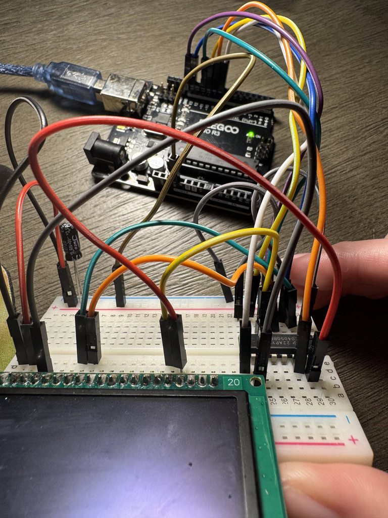 pale sentinel
I have a super dumb question, but I'm new to using radio communications:
I have two radios. I push a start button on the first module and then the second module starts recording data to an SD card. I push a stop button on the first module and then the second module will transmit the SD card data over the radio to the first module which will then write it to its own SD card.
I feel like I need two types of packets: The first telling it to start and stop, the second as just SD card data. Because there's only a 32 byte payload limit, I'd like to maximize the amount of SD card data being sent over per packet.
What's a good way to do this? maybe a packet ID variable in the payload?
pale sentinel
pale sentinel
I have a super dumb question, but I'm new to using radio communications:
I have...
Hey, guess what?! It turns out that the RF24Network actually has this capability built in with its header system. You can set the header to a custom number between 0 and 127 (65-127 if you want auto ack, anything below 64 wont ack), and then just use network.peek() to actually check the header for what type it is, and then decide what to do with that information! HOLY MOLY I WISH THIS WAS BETTER DOCUMENTED
leaden walrus
@carmine tapir please post in the forums with info on the OLED setup:
https://forums.adafruit.com/
and ping me with a link the post when done, i'll follow up there
 fringe carbon
I have been using the jack-o-lantern guide with code to flicker Neopixels to use in a pumpkin. My wife wants to change the color to purple. I tried and the effect is not the same, it flickers many different colors and seems much faster than when using orange color. I thought I could just change the end of the line where variable c (for color) is created. I don't follow the math, but at the end of line it ANDS the value with a hex color that corresponds to orange (0x6A329F) I tried changing the value to a purple 0x39038E3 but effect seems not right
uint32_t c = (((int)(pow((float)y1 / 255.0, 2.7) * 255.0 + 0.5) // Gamma
                 * 0x1004004) >> 8) & 0xFF3F03; // Expand to 32-bit RGB color
https://learn.adafruit.com/circuit-playground-jack-o-lantern/arduino-code

A no-soldering Halloween project
 trail ledge
hey all! anyone know if an arduino nano could power and animate an assessable 3ft led strip with 144 leds? i’m attempting to complete an identity disc protect and absolutely cannot get around the current draw problem
stable forge
trail ledge
hey all! anyone know if an arduino nano could power and animate an assessable 3f...
If a significant number of the LED's are going to be illuminated at the same time, you will probably need a separate power supply. See the detailed description of such a strip here: https://www.adafruit.com/product/1506, and read about its power requirements. And see https://learn.adafruit.com/adafruit-neopixel-uberguide/powering-neopixels and also the rest of that guide
trail ledge
the issue is the space inside the identity disc, i have the room for a maximum of three 18650s, the leds, and the controller, that’s about it
livid osprey
I don’t think I’m familiar with the concept of an “identity disc.” How are the LEDs arranged within your structure?
The regulator on the Arduino nano is rated for 900mA with a heating, so even with additional cooling the regulator is going to limit your power draw. Adding another 5v supply would be ideal if you need the brightness.
merry cargo
livid osprey
I don’t think I’m familiar with the concept of an “identity disc.” How are the L...
Something like this, I'd expect: https://learn.adafruit.com/trondisc

Build an LED TRON Disc
trail ledge
eventually i figured it out, i just used 3 18650s in series which gives me ~11.1v, which is enough to run the LEDs directly
fringe carbon
I have a project with 12 servos running off an Adafruit PCA9685 board.
https://learn.adafruit.com/16-channel-pwm-servo-driver/hooking-it-up
It runs fine when I use this small 3amp variable DC voltage converter.
https://www.amazon.com/dp/B08HQDSQZP
I wanted to have more current for the servos so I ordered this larger board.
https://www.amazon.com/dp/B0CWL8YMRZ
I have wired up the 5v 5amp board but the PCA9685 board will not power on. When I switch it on, the voltage begins to change then drops to zero instantly. I tested the 5 amp converter with a high load and it was providing a stable 2.3 amps of current at 5 volts. I hooked it up to 5 volt Trinket running 60 neopixels and it works fine. I tried another one from the pack and it does the same thing. I even tried another step up converter that outputs about 4.8 volts and the servo board works.
I guess some kind of protection is activating on the 5volt 5amp board? Really stumped at what is going on.


Drive many servos easily

Specification: Module Properties: non-isolated buck Rectification Methods: synchronous rectification Input Voltage: 4.75V-23V Output Voltage: 1.0V-17V Output Current: Peak 3A, long 1.8A Conversion Efficiency: 96% (the highest) Switching Frequency: 340KHz Output Ripple: 340mV (empty cut pm) Load R...

Output voltoge : 5v
Input voltage: 7-20v
Output current : <5a (Long-distance > 4A requires heat dissipation)
Differential pressure: >2v
Operating frequency: 500khz
Conversi on efficiency: 99%(max)
Operating temperature: -40° C~+85° C
Module nature: non-isolated buck
Rectificotio n method:...
leaden walrus
what is the input power source being used?
fringe carbon
leaden walrus
what is the input power source being used?
3S lipo battery. 11.4 volts. I use the same battery on the smaller converter with no issues.
leaden walrus
these are how the output wires from the buck are being connected to the PCA?

no other items in between? these go straight to PCA?
 fringe carbon
leaden walrus
no other items in between? these go straight to PCA?
fringe carbon
leaden walrus
no other items in between? these go straight to PCA?
Yes
 fringe carbon
leaden walrus
any difference if you try connecting via the terminal block?
fringe carbon
leaden walrus
any difference if you try connecting via the terminal block?
Yes thats where I hook it up.
Large board, same hook up, no power.
leaden walrus
the button is just a simple in-line connection with the battery? open/closing connection of battery to setup?
fringe carbon
leaden walrus
the button is just a simple in-line connection with the battery? open/closing co...
Yes On/off switch.
leaden walrus
and the same battery/switch/buck assembly shown works on the other things mentioned?
fringe carbon
leaden walrus
and the same battery/switch/buck assembly shown works on the other things mentio...
Yes first video is battery and switch circuit working with smaller DC converter, 2nd video is with the larger board.
leaden walrus
ok, looked like maybe a different battery in the video
yah, weird behavior
what's the behavior if you solder the power indicator LED jumper and then power the setup disconnected from the PCA?
 fringe carbon
leaden walrus
what's the behavior if you solder the power indicator LED jumper and then power ...
fringe carbon
leaden walrus
what's the behavior if you solder the power indicator LED jumper and then power ...
I now have a red light illuminated with power is applied. And it goes out when i touch the leads to the terminal block
leaden walrus
seems like one of its protection mechanisms is kicking in for some reason
in the video with the smaller buck that works, the neopixel ring and servos come on with power
is the idea the battery/buck will power the entire setup?
fringe carbon
leaden walrus
in the video with the smaller buck that works, the neopixel ring and servos come...
Yes. Its for a pumpkin. I wanted to put a large lipo inside pumpkin and let it run Halloween night
fringe carbon
leaden walrus
seems like one of its protection mechanisms is kicking in for some reason
THIS is the solution/problem. So i touched the top of the terminal blocks with the smaller converter providing volts, then I turned on the larger board, removed the other 5volts and the now the large board stayed ON. So a protection circuit is kicking in. MAYBE because the capacitor on the board
leaden walrus
or possibly just some kind of initial transient, since everything is on
try adding a simple delay() in your sketch
before any of the code that does neopixel or servo stuff
start super conservative with something like delay(1000)
fringe carbon
leaden walrus
or possibly just some kind of initial transient, since everything is on
I will try that later. Thanks for your help
leaden walrus
np. hope it's just something simple like that.
cool looking project
a pumpkin with 12 servo googly eyes and neopixels?
fringe carbon
leaden walrus
cool looking project
Yes. This was a test run.
carmine tapir
I brought this AVR programmer for this project (https://youtu.be/Kp_Hqacm7tM?si=gNUlBLspJFSyGLZg), that uses an ATTiny 85, and I was wondering, for the setup, I was gonna solder the leds/capitator/etc. to the board... but would I not solder the ATTINY85 to the board and instead put it on the AVR programmer, run the code, then would it be transferred to the Tiny85? Cuz how does this guy in the video have it on the board if he had to get the code on there?


A very small yet addictive game running on an ATtiny85 that is mounted onto the back of a 9v battery.
Source code: http://pastebin.com/7kWwrXh6
Inspiration: http://www.raspberrypi.org/archives/1488
ATtiny85 specs: http://www.atmel.com/devices/attiny85.aspx
Charlieplexing: http://en.wikipedia.org/wiki/Charlieplexing
The circuit design is on lin...
carmine tapir
Also is my setup ok / would still work like the one in the video? I couldnt find a board as tiny as he uses but this is what I have so far (I gotta add the GND and else what)
 leaden walrus
they are using headers that have sockets. the headers are soldered onto to the protoboard, but not the attiny.

that way the attiny is removable for programming
its similar to what the programmer itself does
you could use something like this:
https://www.adafruit.com/product/2202
^^ that gets soldered to the protoboard
 dusty seal
Hello, I am not sure if this is the right channel, sorry. I have recently returned to making and bought an Adafruit Feather express with nRF525840 product id 4062. Yesterday, when it was delivered, I opened the package and started following the tutorial mentioned on product page. Installed windows drivers, Arduino ide library. I've chosen the board and COM port. And from tutorial I got a basic blink sketch just to find if board works. When plugged in, the orange led starts rapidly blinking, which seems to be normal afaik. Then I pressed upload and after successful compilation I got
`nordicsemi.exceptions.NordicSemiException: No data received on serial port. Not able to proceed.
Possible causes:
- Selected Bootloader version does not match the one on Bluefruit device.
Please upgrade the Bootloader or select correct version in Tools->Bootloader. - Baud rate must be 115200, Flow control must be off.
- Target is not in DFU mode. Ground DFU pin and RESET and release both to enter DFU mode.`
The tutorial suggested upgrading bootloader if this is happening, so I proceeded to do that but got the same message after choosing the settings and pressing burn bootloader.
So I tried to understand the DFU mode. I found that, to enter it, I need o press reset button twice or to hold user button and then press reset button. The device should blink with red LED. But nothing happens so I think I am unable to enter the DFU mode.
The suggested cause with correct baudrate is something I dont know how to check.
Where did I made a mistake? What can I do to fix this? Thank you in advance.
leaden walrus
dusty seal
Hello, I am not sure if this is the right channel, sorry. I have recently return...
where did you order the board from?
dusty seal
leaden walrus
where did you order the board from?
From Botland, Poland. should be original adafruit. There in Czech Republic is no reseller that has it in stock other than this shop from poland or Mouser but with much higher shipping. 😉 https://botland.cz/desky-kompatibilni-s-arduino-adafruit/21017-feather-nrf52840-express-bluefruit-le-kompatibilni-s-arduino-adafruit-4062.html

BOTLAND
Feather nRF52840 Express Bluefruit LE - kompatibilní s Arduino - Adafruit 4062 z kategorie: Arduino kompatibilní desky - Adafruit k zakoupení v obchodě Botland robotics. Velmi rychlé odeslání!
leaden walrus
dusty seal
From Botland, Poland. should be original adafruit. There in Czech Republic is no...
thanks. this might be a case of needing a replacement. please post this up in the adafruit forums:
https://forums.adafruit.com/
and ping me with a link to the post and i'll follow up there.
if you still have the bag the feather came in, a photo of the white sticker on that bag would help as well if you can add to forum post.
dusty seal
leaden walrus
thanks. this might be a case of needing a replacement. please post this up in th...
thanks, will do.
rapid kraken
I'm trying to use a child class:
class FileLinkedListItem {
  public:
    File current;
    String directory;
    FileLinkedListItem* next;
};

class DirectoryLinkedListItem : public FileLinkedListItem {
  public:
    FileLinkedListItem* last;
};
This is in my main file. Then I have a method in a .ino file:
DirectoryLinkedListItem* expandDirectory(File &dir) {
However, I get:
Compilation error: 'DirectoryLinkedListItem' does not name a type
Any direction at all would be so very appreciated. I'm new to the C/C++ world.
leaden walrus
what do you mean by "main file"? how is that different that your .ino file?
rapid kraken
I have three .ino files, one of which is named after the project/folder, and the other two get compiled in after it.
As far as I understand how Arduino works.
leaden walrus
three tabs open in arduino ide?
rapid kraken
yes
I can use FileLinkedListItem*s in code, jus the derived class that it doesn't like
And only in the declaration of the method and where I call it. Elsewhere in the method, it doesn't object.
rapid kraken
leaden walrus
what are the three files?
Yet another directory listing, powered by Directory Lister.
leaden walrus
yah, arduino probably cant stitch everything together with how they are spread out between files
try re-organizing and move your class code into .h and .cpp files
and then #include that in your main sketch .ino file
rapid kraken
How do you include .h/.cpp files in the sketch?
like, do i just put them in the same folder?
i tried before but it didn't like it and i gave up
leaden walrus
you can just use "New Tab" in the arduino ide and it will create the files
they will end up in the same folder


 rapid kraken
See, I get
Compilation error: LinkedList.h: No such file or directory
leaden walrus
you have a tab named LinkedList.h ?
rapid kraken
yes
leaden walrus
and what is the code line the compilation error is happening on?
leaden walrus
weird it wasnt more robust about that.
but in general "" is for things local (sketch folder) and <> for things elsewhere (like in arduino/lib folder)


 rapid kraken
thank you 🙂
leaden walrus
one set of .cpp/.h files per class
dusty seal
leaden walrus
thanks. this might be a case of needing a replacement. please post this up in th...
Here is a link to forums https://forums.adafruit.com/viewtopic.php?t=220754 Thank you
leaden walrus
dusty seal
Here is a link to forums https://forums.adafruit.com/viewtopic.php?t=220754 Than...
thanks. looks like another support has already responded, so no need for me to reply as well. they'll give you info on how to get a new feather sent out.
proper heart
stable forge
We never ended up selling an MLX30395 breakout, so I think the library developme...
I dived pretty deep into the MLX90395 datasheets last couple weeks and got to work on implementing SPI for library. Everything works perfectly with the current implementation!
This is my fork: https://github.com/FrostiFish/Adafruit_MLX90395
I am nowhere near done, but I was wondering how you feel about merging my fork with the Adafruit version at some point. If so, are there any things, style wise, I should keep in mind?
I could also continue to develop it on my fork and keep it separate.

GitHub
Arduino Library for Adafruit MLX90395 magnetometer - FrostiFish/Adafruit_MLX90395
stable forge
proper heart
I dived pretty deep into the MLX90395 datasheets last couple weeks and got to wo...
Hi - I will ask management.
mental adder
@slim tide, I'll respond here instead of #help-with-projects. I'd recommend retrying the Arduino IDE setup steps, starting from where it says "In the Tools → Board submenu …" at https://learn.adafruit.com/adafruit-qt-py-esp32-pico/arduino-ide-setup onwards.

The cutest ESP32!
 slim tide
mental adder
<@882234318557175809>, I'll respond here instead of <#330406777009209346>. I'd r...
slim tide
mental adder
<@882234318557175809>, I'll respond here instead of <#330406777009209346>. I'd r...
I did everything there. If it helps I used esptools and it gave the same error
I assume it's supposed to automatically set the mode, but I can't find out how exactly
mental adder
slim tide
I assume it's supposed to automatically set the mode, but I can't find out how e...
Try entering the ROM bootloader. The instructions to do so can be found here: https://learn.adafruit.com/adafruit-qt-py-esp32-pico/pinouts#buttons-3119048
slim tide
mental adder
Try entering the ROM bootloader. The instructions to do so can be found here: ht...
I had tried that, but it didn't work, or at least it didn't work with the ide
mental adder
slim tide
I had tried that, but it didn't work, or at least it didn't work with the ide
Also, have you confirmed that the USB cable that you're using can transmit data in addition to power?
slim tide
mental adder
Also, have you confirmed that the USB cable that you're using can transmit data ...
Yep
mental adder
slim tide
Yep
Can you hover your mouse over the Tools menu within the Arduino IDE, and share a screenshot of it?
slim tide
mental adder
Can you hover your mouse over the Tools menu within the Arduino IDE, and share a...
Sure, give me a bit
slim tide
mental adder
Can you hover your mouse over the Tools menu within the Arduino IDE, and share a...
You mean this?
 mental adder
slim tide
I did everything there. If it helps I used esptools and it gave the same error
mental adder
slim tide
I did everything there. If it helps I used esptools and it gave the same error
Assuming you've followed every step on that webpage, including the installation of the USB-to-serial drivers, then I don't have any other ideas. Hopefully someone else can help.
slim tide
mental adder
Assuming you've followed every step on that webpage, including the installation ...
I bought 3 assuming I'd accidentally blow one up or something, I might try another one to make sure it isn't like defective or anything
slim tide
mental adder
Assuming you've followed every step on that webpage, including the installation ...
Well I'll be contacting Adafruit for a refund
2nd one worked
(I probably messed something up so I'll try a factory reset first)
Thanks for the help!
stable forge
slim tide
Thanks for the help!
Open a thread in https://forums.adafruit.com if you don't succeed. That is the official support channel.
 untold depot
Howdy folks, I'm running this very simple test code:
void setup() {
  // put your setup code here, to run once:
  Serial.begin(9600);
  pinMode(7, OUTPUT);
}

void loop() {
  // put your main code here, to run repeatedly:
  Serial.println(x);
  delay(5000);
  if (x % 2 == 0) {
    digitalWrite(7, HIGH);
  }
  else {
    digitalWrite(7, LOW);
  }
  x++;
}```

but for some reason, I stop receiving serial messages after the first one. I know the code is still executing because the built-in LED is still blinking. I've tried swapping out usb cables, multiple Feather RP2040 (and one RP2350 as shown) boards, even tried a different computer, they all do the same thing. If I set the delay to only 1000 though, I get full communication for hundreds of loops. I've googled my brains out and can't find anything about RP20xx boards doing this. What's going on?are you using the philhower arduino core or something else?
I was trying with this, very similar:
void setup() {
  Serial.begin(9600);
  //while (!Serial) {}
  // initialize digital pin LED_BUILTIN as an output.
  pinMode(LED_BUILTIN, OUTPUT);
}

int i = 0;
// the loop function runs over and over again forever
void loop() {

  Serial.println(i);
  digitalWrite(LED_BUILTIN, HIGH);  // turn the LED on (HIGH is the voltage level)
  delay(5000);                      // wait for a second
  digitalWrite(LED_BUILTIN, LOW);   // turn the LED off by making the voltage LOW
  delay(5000);                      // wait for a second
  i++;
}
it's working OK for me
what is the host computer or the Serial receiver here?
untold depot
stable forge
are you using the philhower arduino core or something else?
I'm using the philhower core, yes
untold depot
stable forge
what is the host computer or the Serial receiver here?
right now it's a framework 13 running debian 12
stable forge
untold depot
I'm using the philhower core, yes
Try my test above, with and without the while (!Serial) {} commented out. When it stops working, does /dev/ttyACM0 disappear?
are you just using the Serial monitor in the Arduino IDE? Which version of Arduino IDE are you using, the latest 2.x.x?
You could also connect with a terminal program. I like tio.
untold depot
stable forge
Try my test above, with and without the `while (!Serial) {}` commented out. When...
it doesn't disconnect with or without the loop commented out.
untold depot
stable forge
are you just using the Serial monitor in the Arduino IDE? Which version of Ardui...
2.3.6, and tio has the same problem
stable forge
untold depot
it doesn't disconnect with or without the loop commented out.
I'm confused, do you mean my test program works ok, but yours doesn't?
untold depot
stable forge
I'm confused, do you mean my test program works ok, but yours doesn't?
sorry, both your test and my test don't disconnect from /dev/ttyACM0 (as if I had used Serial.end()) it just doesn't receive text input.