#help-with-arduino
1 messages · Page 20 of 1
 north stream
The idea of this Discord is to help everybody, information in DMs doesn't do that. Additionally, people (including me) come and go during the day
 icy dome
ok, no problem! 🙂
I'll post the code of the animation, without any button in it
and I'd start from this for the buttons:
buttonState = digitalRead(buttonPin);
if (buttonState == HIGH) {
do something
} else {
turn back to the previous state
}
in void loop
north stream
Maybe in setup() have something like ```arduino
pinMode(buttonPin, INPUT_PULLUP);
randomSeed(analogRead(A0));
And then in loop(), have something like ```arduino
if (!digitalRead(buttonPin)) {
for (int led = 0; led < NUM_LEDS; ++led) {
leds[led] = setRGB(random(255), random(255), random(255));
}
}
It would basically reset the colors when the button was pressed (really: over and over as long as the button is held down), with no notion of a previous state
if you preferred, you could do a subset of the LEDs instead of all of them, or set a row of N to the same random color, or whatever you wanted
icy dome
north stream
And then in `loop()`, have something like ```arduino
if (!digitalRead(buttonPin)...
I got an error here
"'setRGB' was not declared in this scope"
north stream
That's what I get for coding when I just woke up. Try leds[led].setRGB(random(255), random(255), random(255));
icy dome
oh great that's working, but now the question is:
if I want to change the led color but keep the animation that's going on, is it possible?
the led color inside the animation I mean
void setup() {
FastLED.addLeds<SK6812, DATA_PIN, GRB>(leds, NUM_LEDS);
FastLED.setBrightness(100);
FastLED.clear();
pinMode(buttonPin1, INPUT_PULLUP);
randomSeed(analogRead(5));
// Frame 1
leds[0].setRGB(150, 0, 255);
leds[1].setRGB(150, 0, 255);
leds[2].setRGB(150, 0, 255);
leds[3].setRGB(150, 0, 255);
I mean this value here
north stream
It is possible, but it's a little tricker. It looks like the current setup is 4 LEDs have a non-black color and the rest are black. So you could modify the updater to just choose another (non-black) color and only update the LEDs that are currently non-black.
icy dome
could you explain it better, please?
north stream
I'm thinking something like this:
bool allblack(CRGB color)
{
  if color.r != 0:
    return FALSE;

  if color.g != 0:
    return FALSE;

  if color.b != 0:
    return FALSE;

  return TRUE;
}

if (!digitalRead(buttonPin)) {
    CRGB newcolor;

    // choose a color that is not black
    while (allblack(newcolor)) {
      newcolor.r = random(255);
      newcolor.g = random(255);
      newcolor.b = random(255);
    }

    for (int led = 0; led < NUM_LEDS; ++led) {
        if (!allblack(leds[led]) {
          leds[led] = newcolor;
        }
    }
}
So when it's time to update, it chooses a new color that is not black, then it goes through all the LEDs and replaces any that are not black with the new color
icy dome
it looks nice, I'll test it
this has to be put in setup? or outside?
north stream
The allblack() routine goes outside, the stuff from digitalRead() on replaces the old stuff in loop()
icy dome
thanks
I get two errors
error: expected '(' before 'color'
if color.b != 0:
error: expected ')' before '{' token
if (!allblack(leds[led]) {
 manic nimbus
Missing an extra close paren after leds[led]
There should be two. One for the function call, one for the if conditional
icy dome
ok, thanks, wait
error: 'FastLED' does not name a type
FastLED.show();
and also:
error: expected ')' before '{' token
if (!allblack(leds[led]) {
icy dome
icy dome
and also:
error: expected ')' before '{' token
if (!allblack(leds[led]...
this now is ok
icy dome
icy dome
error: 'FastLED' does not name a type
FastLED.show();
for this I don't know what it wants
 sullen loom
I think there are some confusions on the pins I'm using. I'm using the Left and Right pins from the TRRS to convert the stereo audio to mono, but I want to use the RSw(from what I found online, I only need to use one of the switch pins) to detect when an aux cable is plugged in. It looks like the RSw pin (Yellow) needs to be connected to a pullup resistor but I can't figure out how to make it work. For testing, I'm trying to turn on the internal LED from the ESP32 when the aux cable is connected and turn off when I remove the cable. I want to use the RSw to detect the aux cable.
 north stream
I understand that. But putting a capacitor in series with the signal will cause it to not work.
sullen loom
north stream
I understand that. But putting a capacitor in series with the signal will cause...
How do I make the audio input and the RSw work? I can detect the audio fine with this setup
north stream
I'd try removing the capacitor entirely. Possibly the resistors too.
sullen loom
If I remove the capacitor and the resistors, will the microcontroller be damaged if the incoming audio is too loud? I'm using my phone to play music
icy dome
icy dome
error: 'FastLED' does not name a type
FastLED.show();
@north stream , no solution for this error?
north stream
icy dome
this now is ok
Add a close parenthesis and it should fix both errors
north stream
sullen loom
If I remove the capacitor and the resistors, will the microcontroller be damaged...
I thought those pins were the switch pins. They shouldn't have any audio (unless it's a different kind of jack where the switch pins connect to signal instead of ground, I don't know)
icy dome
just done, but nothing fixed
error: expected '(' before 'color'
if color.r != 0:
and also this
north stream
Oh yeah, you need parentheses around those expressions (again, coding before I fully wake up - I was hoping you'd spot and fix my errors)
So they'd look like ```arduino
if (color.r != 0) {
return FALSE;
}
I had been thinking in Python
icy dome
north stream
Oh yeah, you need parentheses around those expressions (again, coding before I f...
man I'm sorry, but if I knew it, I'd not ask 😓
north stream
Change all three of them like the sample I did for red
icy dome
I changed, now that error seems ok, but still asking for that FastLED error, as it misses a close parentesis
ok, fixed also this one
but still this error:

 north stream
Make it look like my example: you put parentheses around the expression, but you also need to delete the colon (and ideally put an open brace after the close parenthesis and a close brace after the return statement
icy dome
{
if (color.r != 0)
{
return FALSE;
}
if (color.g != 0)
{
return FALSE;
}
if (color.b != 0)
{
return FALSE;
}
{
return TRUE;
}
}
you mean something like that?
it looks correct, but still get an error
error: expected unqualified-id before '{' token
{
and I would specify that I'm putting this outside, after bool allblack(CRGB color);
north stream
You don't need braces around the final return TRUE one
north stream
Still get which error?
 manic nimbus
What's on line 13?
icy dome
this

 livid osprey
icy dome
this
livid osprey
icy dome
this
Remove the semicolon at the end of line 12.

 livid osprey
Change them to lowercase.
icy dome
jeez, sorry guys
didn't look at it
now test it
ok guys, it works, but only one time
I mean, first time I press the button it changes the animation color, but if I press it again, nothing happens
icy dome
this is the full code now:
livid osprey
icy dome
this is the full code now:
Your while loop that generates a random non black color doesn’t ever run after the first time because newcolor is no longer black. In your if(!button) statement, you need to reset newcolor to 0,0,0 in order to generate a new random color.
icy dome
uhm
 muted gyro
random info/rant maybe interesting for someone here:
Adafruit GFX doesn't work when using the Arduino online editor. I would expect that other adafruit libraries are also affected.
To reproduce, just open the Adafruit GFXcanvas example. It doesn't compile. (1st screenshot) It tries to use some library called "EIS" to get Adafruit_I2CDevice.h instead of the original Adafruit BusIO library.
Fix: manually include Adafruit BusIO at the top of your .ino sketch.
I think this library is the culprit: https://github.com/DBSStore/EIS/tree/v0.0.1 They copy-pasted a ton of Adafruit-library files into their library. (without crediting adafruit and without including the adafruit license too)

 icy dome
livid osprey
Your while loop that generates a random non black color doesn’t ever run after t...
icy dome
livid osprey
Your while loop that generates a random non black color doesn’t ever run after t...
I'm sorry, but I don't know how to do this, I'm going to ask if you can write this code for me, cause I'm a bit inexperienced on Arduino coding
icy dome
Anyone to help, please? 🥹
north stream
Maybe, if you're in no hurry at all
icy dome
Of course! Sorry, I didn't want to get hurry 🫶🏻
 vague shale
same here
Also, anyone know how to compile arduino code with PlatformIO with VSCode for the Playground Express?
livid osprey
icy dome
I'm sorry, but I don't know how to do this, I'm going to ask if you can write th...
if (!digitalRead(buttonPin1)) {
  CRGB newcolor;
  newcolor.r = 0;
  newcolor.g = 0;
  newcolor.b = 0;
  // choose a color that is not black
  while (allblack(newcolor)) {
    newcolor.r = random(255);
    newcolor.g = random(255);
    newcolor.b = random(255);
  }
Thanks man, I'm going to test it in an hour
icy dome
livid osprey
```arduino
if (!digitalRead(buttonPin1)) {
CRGB newcolor;
newcolor.r = 0;
...
ok, man it's working on one button (buttonPin1)
what if I would do it on X buttons (buttonPinX)? is it enough to repeat the function and change the buttonPin?
thanks a lot 🙂
 mighty elbow
https://buildmusic.net/ So I'm going to attempt to build this. I have a question: Is it POSSIBLE to have the sound of the midi on a soundfont play as the physical xylophone is playing?

The Robotic Xylophone that you can build to play your favorite songs.
if so how?
This basically uses midi to have the Xylophone play on its own
you only hear the Xylophone and ideally I'd like to modify this so that the midi plays on an organ soundfont ON TOP of the xtylophone
This runs off 5 arduinos so I have a lot of wiring to do when the parts arrive
north stream
Yeah, it's possible. There are three main ways I can think of. The simplest is having something like optical sensors detect when the bars are struck and triggering the appropriate note. Next is having something like piezoelectric sensors on the bars themselves which can detect when the bar is vibrating. This would take more processing, but would have the advantage of being able to give some measure of how loudly a given bar is vibrating. The most complicated implementation (with the simplest sensor) would have a microphone listen to the xylophone and do a lot of processing to figure out which notes were sounding. This would be further complicated by the need to separate out the sounds from the soundfont from the sounds of the physical instrument.
mighty elbow
What if I somehow also had a midi socket in one of the arduinos and have that connected to a midi sound module set to an organ sound?
so the midi thats being fed into the xylophone module is also playing through a midi sound module
Not sure if I'm explaining correctly
Though the cheapest midi sound module I could find was 80 bucks provided I can't build a one myself
livid osprey
Splitting the midi signal to multiple outputs is absolutely possible. You may need to introduce a small delay to synchronize the physical hits to the digital MIDI output, but that shouldn't be a dealbreaker.
icy dome
livid osprey
```arduino
if (!digitalRead(buttonPin1)) {
CRGB newcolor;
newcolor.r = 0;
...
i've done it, thanks 🙂
mighty elbow
livid osprey
Splitting the midi signal to multiple outputs is absolutely possible. You may ne...
When I get to that point can I dm you? I need to wait for all the parts before I start
 golden matrix
mighty elbow
This basically uses midi to have the Xylophone play on its own
golden matrix
mighty elbow
This basically uses midi to have the Xylophone play on its own
It's definitely possible. What do you want to use to play the soundfont? At a glance it seems the slave boards are daisy chained and pass the entire message to each other, so you could add another board in the chain to handle that. Alternatively you could use I2C out of the master arduino to send the signal to whatever you use to play the organ. Replacing the master with a mega would also give you more options.
mighty elbow
I actually have a mega too
can I use an arduino to play the sound font? (which will literally just be a general midi organ sound)
I need to find a midi sound module if not
Are there any cheap options?
I know there’s a professional one but it’s 80 bucks and it’s a bit overkill
 stable forge

Bend all audio files to your will with the Adafruit Music Maker FeatherWing! It's a fun-size version of our Music Maker shield for Arduino! This powerful wing features the ...

This breakout board is the ultimate companion for the VLSI VS1053B DSP codec chip. The VS1053 can decode a wide variety of audio formats such as MP3, AAC, Ogg Vorbis, WMA, MIDI, FLAC, WAV ...

Bend all audio files to your will with the Adafruit Music Maker shield for Arduino! This powerful shield features the VS1053, an encoding/decoding (codec) chip that can decode a wide variety ...
stable forge
mighty elbow
Are there any cheap options?
see above. All use VS1053 which has a MIDI synth onboard
I don't know how it sounds
stable forge
mighty elbow
can I use an arduino to play the sound font? (which will literally just be a gen...
mighty elbow
stable forge
see above. All use VS1053 which has a MIDI synth onboard
Thank you!
golden matrix
I don’t think Arduinos can play sounds other than a square wave buzz. Danh sent some good options though
mighty elbow
I’m going to experiment with one of these
But I plan to get the main xylophone part working first
I have to wait for a lot of parts
 amber loom
Hello. I'm new. I just came from the 'help-with-circuitpython' group. They told me to switch to arduino.
I'm using a Qualia ESP32-S3 and Round RGB 666 TTL TFT Display.
My goal = To display a looping 480x480 pixel video (mp4 or mjpeg) on the 480x480 screen.
Could someone help me with the simplest code possible to achieve this? Happy to be led to a tutorial if it matches what I'm after.
 eternal cloud
amber loom
Hello. I'm new. I just came from the 'help-with-circuitpython' group. They told ...
eternal cloud
amber loom
Hello. I'm new. I just came from the 'help-with-circuitpython' group. They told ...
You already have the code in the guide for the video https://learn.adafruit.com/qualia-s3-fireplace/software-setup-and-use
amber loom
Yes, but that one has multiple videos and references to touch screens and so on. I just want something simple and readable to a noob (me).
eternal cloud
amber loom
Yes, but that one has multiple videos and references to touch screens and so on....
This is a project code, there isn't anything simpler already written. And if you're using the exact hardware described in the project, you don't have to edit the code, or even compile it.
You can put your videos on the SD card, drag and drop the UF2 image on the board, done
amber loom
I don't have an SD card. I'm using the internal memory
eternal cloud
You can't do that in arduino.
amber loom
wot 😮
Guess I need to go buy a micro SD then
How does this look:
`#define MJPEG_FOLDER "/videos"
#define MJPEG_OUTPUT_SIZE (820 * 320 * 2)
#define MJPEG_BUFFER_SIZE (MJPEG_OUTPUT_SIZE / 5)
#include <Arduino_GFX_Library.h>
#include <SD_MMC.h>
#include "MjpegClass.h"
Arduino_XCA9554SWSPI *expander = new Arduino_XCA9554SWSPI(
PCA_TFT_RESET, PCA_TFT_CS, PCA_TFT_SCK, PCA_TFT_MOSI, &Wire, 0x3F);
Arduino_ESP32RGBPanel *rgbpanel = new Arduino_ESP32RGBPanel(
TFT_DE, TFT_VSYNC, TFT_HSYNC, TFT_PCLK,
TFT_R1, TFT_R2, TFT_R3, TFT_R4, TFT_R5,
TFT_G0, TFT_G1, TFT_G2, TFT_G3, TFT_G4, TFT_G5,
TFT_B1, TFT_B2, TFT_B3, TFT_B4, TFT_B5,
1, 50, 2, 44, 1, 16, 2, 18);
Arduino_RGB_Display *gfx = new Arduino_RGB_Display(
320, 820, rgbpanel, 0, true, expander, GFX_NOT_DEFINED, tl032fwv01_init_operations, sizeof(tl032fwv01_init_operations));
static MjpegClass mjpeg;
File mjpegFile, video_dir;
uint8_t *mjpeg_buf;
uint16_t *output_buf;
void setup() {
Wire.setClock(400000);
gfx->begin();
gfx->fillScreen(BLUE);
SD_MMC.setPins(SCK, MOSI, MISO, A0, A1, SS);
SD_MMC.begin("/root", true);

video_dir = SD_MMC.open(MJPEG_FOLDER);
mjpeg_buf = (uint8_t *)malloc(MJPEG_BUFFER_SIZE);
output_buf = (uint16_t *)heap_caps_aligned_alloc(16, MJPEG_OUTPUT_SIZE, MALLOC_CAP_8BIT);
}
void loop() {
if (mjpegFile) mjpegFile.close();
mjpegFile = video_dir.openNextFile();
if (!mjpegFile || mjpegFile.isDirectory()) {
    esp_sleep_enable_timer_wakeup(1000);
    esp_deep_sleep_start();
}

mjpegFile.seek(0);
if (!mjpeg.setup(&mjpegFile, mjpeg_buf, output_buf, MJPEG_OUTPUT_SIZE, true)) {
    return; // Handle setup failure
}

while (mjpegFile.available() && mjpeg.readMjpegBuf()) {
    mjpeg.decodeJpg();
    int w = mjpeg.getWidth();
    int h = mjpeg.getHeight();
    int x = (gfx->width() - w) / 2;
    int y = (gfx->height() - h) / 2;
    gfx->draw16bitBeRGBBitmap(x, y, output_buf, w, h);
}
}
`
But change the 820320 to 480480
livid osprey
eternal cloud
You can't do that in arduino.
It’s not recommended for beginners, but there is SPIFFS for esp32. Technically it is possible to modify the project to use that…
sullen loom
north stream
I thought those pins were the switch pins. They shouldn't have any audio (unles...
I want to use the RSw to detect the aux cable
 north stream
sullen loom
I want to use the RSw to detect the aux cable
north stream
sullen loom
I want to use the RSw to detect the aux cable
Yes, I get that. Is this jack an input or an output? What kinds of signals are on it?
sullen loom
north stream
Yes, I get that. Is this jack an input or an output? What kinds of signals are...
The jack is an input. It’s whatever sound will come out of my phone
 tardy iron
sullen loom
The jack is an input. It’s whatever sound will come out of my phone
tardy iron
sullen loom
The jack is an input. It’s whatever sound will come out of my phone
are you using a TRS or TRRS plug coming from the phone?
sullen loom
I was using a TRRS plug but I also have TRS that I just order but I haven’t tried it yet.
tardy iron
i’d check for mic power on the sleeve (assuming a modern pinout) or for shorting to ground (TRS plug) instead of relying on the switch pins. the switch pins are somewhat easier to use if the jack is an output, because you don’t have to worry about backfeeding an output on the other end
 elfin hare
interesting. https://learn.adafruit.com/adafruit-rs232-pal/arduino says no additional libraries are needed, but when I run the sample code it says that the SoftwareSerial.h library is not found. 🤔

A pal for your RS-232 devices
Probably because that library comes with the Metro, but not the QT Py ESP32 Pico I'm using
stable forge
elfin hare
Probably because that library comes with the Metro, but not the QT Py ESP32 Pico...
I was just looking, yes, it's on classic Arduino boards. But for boards like the QT Py, you can use most pins for hw serial
 hard dune
hey, I have a flora board but can’t see the board listed on Arduino IDE 2.3.3. Any help would be greatly appreciated
livid osprey
hard dune
hey, I have a flora board but can’t see the board listed on Arduino IDE 2.3.3. A...
Addressed in #general-chat. In the future, please don't post the same inquiry in multiple channels at the same time.
amber loom
livid osprey
It’s not recommended for beginners, but there is SPIFFS for esp32. Technically i...
After installing Arduino IDE and connecting to the board, I tried downloading 'esp32fs.jar' into 'E:\Documents\Arduino\tools\ESP32FS\tool' and nothing new appears in the 'tools' menu of Arduino IDE. Another dead end there.
How Do I connect an SD or microSD card to my Adafruit Qualia ESP32-S3? There is no card reader.
Please keep advice simple, layman's terms.
What do I need to buy? I only have a week left to get this done.
I'm going to try an animated GIF again, but failing that I'll use mjpeg or Mp4. Here's the code so far:
`#include <SPI.h>
#include <FS.h>
#include <SPIFFS.h>
#include <AnimatedGIF.h>
#include <Adafruit_GFX.h>
#include <Adafruit_ILI9341.h> // Change based on your display driver
#define TFT_CS 15
#define TFT_RST 16
#define TFT_DC 17
Adafruit_ILI9341 tft = Adafruit_ILI9341(TFT_CS, TFT_DC, TFT_RST);
AnimatedGIF gif;
void setup() {
Serial.begin(115200);
tft.begin();
tft.setRotation(1);
tft.fillScreen(ILI9341_BLACK);
if (!SPIFFS.begin(true)) {
Serial.println("SPIFFS Mount Failed");
return;
}
if (gif.open("/portal.gif", GIFOpenFile, GIFCloseFile, GIFReadFile, GIFSeekFile, GIFDraw)) {
Serial.println("GIF opened successfully");
} else {
Serial.println("Failed to open GIF");
}
}
void loop() {
while (gif.playFrame(true, NULL)) {
// Loop until the GIF is finished
}
gif.close();
delay(1000); // Delay before restarting
}
void GIFDraw(GIFDRAW *pDraw) {
tft.drawRGBBitmap(pDraw->iX, pDraw->iY, pDraw->pPixels, pDraw->iWidth, pDraw->iHeight);
}
// File handling functions
void *GIFOpenFile(const char *fname, int32_t *pSize) {
File f = SPIFFS.open(fname, "r");
*pSize = f.size();
return (void *)&f;
}
void GIFCloseFile(void *pHandle) {
File *f = (File *)pHandle;
f->close();
}
int32_t GIFReadFile(GIFFILE *pFile, uint8_t *pBuf, int32_t iLen) {
File *f = (File *)pFile->fHandle;
return f->read(pBuf, iLen);
}
int32_t GIFSeekFile(GIFFILE *pFile, int32_t iPosition) {
File *f = (File *)pFile->fHandle;
f->seek(iPosition);
return f->position();
}
`
livid osprey
amber loom
How Do I connect an SD or microSD card to my Adafruit Qualia ESP32-S3? There is ...
You'll need to buy a breakout to add a card slot to your Qualia. https://learn.adafruit.com/2-1-round-ornament-tft/circuit-diagram shows the connections needed for the SD card breakout, for your reference.
amber loom
Whelp, that's not going to arrive in time
livid osprey
I don't have any idea what esp32fs.jar is, I don't recall ever using any such tool in my very brief experiments with SPIFFS.
amber loom
Maybe I chose the wrong one?
GitHub
Arduino plugin for uploading files to ESP32 file system - me-no-dev/arduino-esp32fs-plugin
Is this what I need to transfer files to the ESP32-S3's memory?
livid osprey
amber loom
Maybe I chose the wrong one?
What version of Arduino IDE are you using?
livid osprey
Yup, that's the wrong one. That only works for 1.8 IIRC.
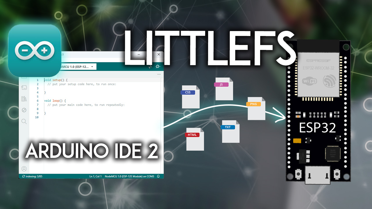
Upload files to the ESP32 LittleFS Filesystem using Arduino IDE 2 or a higher version. We'll install an uploader plugin that will add a new menu to the Arduino IDE.
amber loom
Ty I'll try right now
arduino-littlefs-upload-1.3.0.vsix

GitHub
This release rewrites the ESP32 partitions.csv support to allow for things like using "M" and "K" to specify partition sizes, as well as automatic sequential assignment of addre...
livid osprey
I believe so
amber loom
Currently stuck on Step #2. Can't find the folder on the computer it's after, haha
nvm got it
amber loom
Windows. Up to the uploading step. Stuck on Step 7
"
ERROR: Partition file not found!"
Sketch Path: E:\Documents\Arduino\sketch_nov15b
Data Path: E:\Documents\Arduino\sketch_nov15b\data
Device: ESP32 series, model esp32s3
Using partition: tinyuf2
Partitions: C:\Users\jvill\AppData\Local\Arduino15\packages\esp32\hardware\esp32\3.0.5\tools\partitions\tinyuf2.csv
Should I change the partition scheme?
I tried every partition scheme and 4x had the same error. 2x said not enough space, but recognised the file I wanted to copy over.


I went to that folder and the partition file does indeed not exist:
 livid osprey
amber loom
I tried every partition scheme and 4x had the same error. 2x said not enough spa...
livid osprey
amber loom
I tried every partition scheme and 4x had the same error. 2x said not enough spa...
How large a file is it? I believe you need a scheme with a large enough littlefs/spiffs partition.
amber loom
I manually created the tinyuf2 file myself with this code:
ESP-IDF Partition Table
Name, Type, SubType, Offset, Size, Flags
bootloader.bin,, 0x1000, 32K
partition table,, 0x8000, 4K
nvs, data, nvs, 0x9000, 0x6000, # 24 KB for NVS
otadata, data, ota, 0xf000, 0x2000, # 8 KB for OTA data
app0, app, ota_0, 0x10000, 0x7C000, # 508 KB for App0
app1, app, ota_1, 0x8FC000, 0x7C000, # 508 KB for App1
spiffs, data, spiffs, 0x17FC000, 0x3F0000, # 4 MB for SPIFFS
The GIF is 3.65mb

COM port was wrong for some reason, so I had to fix that. The error above is what I get.
I'm guessing the GIF is too big? Kind of silly how CircuitPy had like 32Mb of partition space to play with, but had s###ty code, and Arduino only let's me have like... 2 mb.
These partition schemes don't seem to have the files matching, meaning I had to make my own partition files.

I'll come back for more assistance tomorrow. 😦
livid osprey
Large SPIFFS didn’t take…?
amber loom
The custom one I made above? No.
Oh this one?

I'll try to make it now.
Using this partition table for 'large_spiffs':
ESP-IDF Partition Table
Name, Type, SubType, Offset, Size, Flags
bootloader.bin,, 0x1000, 32K
partition table,, 0x8000, 4K
nvs, data, nvs, 0x9000, 0x6000, # 24 KB for NVS
otadata, data, ota, 0xf000, 0x2000, # 8 KB for OTA data
app0, app, ota_0, 0x10000, 0x480000,
app1, app, ota_1, 0x488000, 0x480000,
spiffs, data, spiffs, 0x900000, 0x6A0000,
Looks like it's working, 1 moment.

You're a genius, Hem

So now I just need to get the code right.
amber loom
I'm trying to code with Arduino, but I have no idea what I'm doing. The online tutorial isn't helpful. Just trying to play an Animated GIF.
Adafruit Qualia ESP32-S3
amber loom
I'm trying to keep the code basic to begin with, just trying to make the screen red. This code doesn't produce any errors, but nothing comes up on the screen either:
`#include <Adafruit_GFX.h> // Core graphics library
#include <Adafruit_ILI9341.h> // Library for ILI9341 display
#include <Wire.h> // Include if I2C communication is needed
// Create the display object with typical SPI pin configurations
#define TFT_CS 10 // Chip select pin
#define TFT_DC 9 // Data/command pin
#define TFT_RST 8 // Reset pin (can be set to -1 if connected to ESP32 reset)
#define TFT_MOSI 11 // MOSI pin
#define TFT_SCLK 12 // Clock pin
Adafruit_ILI9341 display(TFT_CS, TFT_DC, TFT_RST);
void setup() {
// Start serial communication for debugging
Serial.begin(115200);
// Initialize the display
display.begin();
// Set up display
display.fillScreen(ILI9341_RED); // Fill the screen with red
Serial.println("Display initialized and set to red.");
}
void loop() {
// Nothing needed here for just displaying a static color
}
`
I hate this code.
north stream
There's not much to hate, the code doesn't do much
amber loom
Okay? So... what am I doing wrong?
`#include <TFT_eSPI.h> // Core graphics library
// Initialize the TFT display
TFT_eSPI tft = TFT_eSPI(); // Create TFT object
// Define color constants
#define TFT_RED 0xF800 // RGB565 for red
// Initialization sequence
const uint8_t init_sequence[] = {
0xff, 0x05, 0x77, 0x01, 0x00, 0x00, 0x13,
0xef, 0x01, 0x08,
0xff, 0x05, 0x77, 0x01, 0x00, 0x00, 0x10,
0xc0, 0x02, 0x3b, 0x00,
0xc1, 0x02, 0x10, 0x0c,
0xc2, 0x02, 0x07, 0x0a,
0xc7, 0x01, 0x00,
0xcc, 0x01, 0x10,
0xcd, 0x01, 0x08,
0xb0, 0x10, 0x05, 0x12, 0x98, 0x0e, 0x0f, 0x07, 0x07, 0x09, 0x09, 0x23, 0x05, 0x52, 0x0f, 0x67, 0x2c, 0x11,
0xb1, 0x10, 0x0b, 0x11, 0x97, 0x0c, 0x12, 0x06, 0x06, 0x08, 0x08, 0x22, 0x03, 0x51, 0x11, 0x66, 0x2b, 0x0f,
0xff, 0x05, 0x77, 0x01, 0x00, 0x00, 0x11,
0xb0, 0x01, 0x5d,
0xb1, 0x01, 0x2d,
0xb2, 0x01, 0x81,
0xb3, 0x01, 0x80,
0xb5, 0x01, 0x4e,
0xb7, 0x01, 0x85,
0xb8, 0x01, 0x20,
0xc1, 0x01, 0x78,
0xc2, 0x01, 0x78,
0xd0, 0x01, 0x88,
0xe0, 0x03, 0x00, 0x00, 0x02,
0xe1, 0x0b, 0x06, 0x30, 0x08, 0x30, 0x05, 0x00, 0x07, 0x00, 0x33,
0xe2, 0x0c, 0x11, 0x11, 0x33, 0xf4, 0x00, 0x00, 0x00, 0xf4, 0x00, 0x00, 0x00,
0xe3, 0x04, 0x00, 0x00, 0x11, 0x11,
0xe4, 0x02, 0x44, 0x44,
0xe5, 0x10, 0x0d, 0xf5, 0x0f, 0xf0, 0x0f, 0xf7, 0x0f, 0xf0, 0x09, 0xf1, 0x0f, 0xf0, 0x0b, 0xf3, 0x0f, 0x00,
0xe6, 0x04, 0x00, 0x00, 0x11, 0x11,
0xe7, 0x02, 0x44, 0x44,
0xe8, 0x10, 0x0c, 0xf4, 0x0f, 0xf0, 0x0e, 0xf6, 0x0f, 0xf0, 0x08, 0xf0, 0x0a, 0xf2, 0x0f, 0x00,
0xe9, 0x02, 0x36, 0x01,
0xeb, 0x07, 0x00, 0x01, 0xe4, 0xe4, 0x44, 0x88, 0x40,
0xed, 0x10, 0xff, 0x10, 0xaf, 0x76, 0x2b, 0xcf, 0xff, 0xff, 0xfc, 0xb2, 0x45, 0x67, 0xfa, 0x01, 0xff,
0xef, 0x06, 0x08, 0x08, 0x08, 0x45, 0x3f, 0x54,
0xff, 0x05, 0x77, 0x01, 0x00, 0x00, 0x00,
0x11, 0x80, 0x78,
0x3a, 0x01, 0x66,
0x36, 0x01, 0x00,
0x35, 0x01, 0x00,
0x29, 0x80, 0x32
};
`
`
// Timing parameters
struct TFTTiming {
uint32_t frequency;
uint16_t width;
uint16_t height;
uint16_t hsync_pulse_width;
uint16_t hsync_back_porch;
uint16_t hsync_front_porch;
bool hsync_idle_low;
uint16_t vsync_pulse_width;
uint16_t vsync_back_porch;
uint16_t vsync_front_porch;
bool vsync_idle_low;
bool pclk_active_high;
bool pclk_idle_high;
bool de_idle_high;
};
TFTTiming tft_timings = {
15000000, // frequency
480, // width
480, // height
2, // hsync_pulse_width
10, // hsync_back_porch
10, // hsync_front_porch
false, // hsync_idle_low
6, // vsync_pulse_width
10, // vsync_back_porch
10, // vsync_front_porch
false, // vsync_idle_low
true, // pclk_active_high
false, // pclk_idle_high
false // de_idle_high
};
void setup() {
tft.init(); // Initialize the display
tft.setRotation(1); // Set rotation if needed
// Send the initialization sequence
for (size_t i = 0; i < sizeof(init_sequence); i++) {
    tft.writecommand(init_sequence[i]);
}

// Fill the screen with red
tft.fillScreen(TFT_RED);
}
void loop() {
// Nothing to do here
}
Can't even get the screen to turn red.
north stream
I can only guess. Perhaps the screen doesn't match that driver, perhaps the screen is misconfigured, or there could be a wiring problem
livid osprey
amber loom
Okay? So... what am I doing wrong?
`#include <TFT_eSPI.h> // Core graphics libr...
Try using https://learn.adafruit.com/adafruit-qualia-esp32-s3-for-rgb666-displays/arduino-rainbow-demo as your basis and see if that gets your display working.

Use the new Qualia ESP32-S3 to add a higher resolution Dot Clock RGB-666 Display to your next project
 cold lagoon
Hey. I'm currently building a keyboard with an rp2040 and the earlephilhower core. My question is, would it be possible to get NKRO to work if so how?
stable forge
cold lagoon
Hey. I'm currently building a keyboard with an rp2040 and the earlephilhower cor...
you need the right HID report descriptor. We have a write-up for CircuitPython here: https://learn.adafruit.com/custom-hid-devices-in-circuitpython/n-key-rollover-nkro-hid-device but you could use the same idea in philhower/arduino
amber loom
livid osprey
Try using https://learn.adafruit.com/adafruit-qualia-esp32-s3-for-rgb666-display...
Error with the very first line of code. The library is not recognised (even when installed).


Even the most basic tutorial doesn't work.
amber loom
And now I have no idea what to do.
amber loom
Pretty sure the beginning of my code needs to be:
`#include <Arduino_GFX_Library.h>
#include <Adafruit_FT6206.h>
#include <Adafruit_CST8XX.h>
#include <AnimatedGIF.h>
#include <FS.h>
#include <SPIFFS.h>
Arduino_XCA9554SWSPI *expander = new Arduino_XCA9554SWSPI(
PCA_TFT_RESET, PCA_TFT_CS, PCA_TFT_SCK, PCA_TFT_MOSI,
&Wire, 0x3F);
Arduino_ESP32RGBPanel rgbpanel = new Arduino_ESP32RGBPanel(
TFT_DE, TFT_VSYNC, TFT_HSYNC, TFT_PCLK,
TFT_R1, TFT_R2, TFT_R3, TFT_R4, TFT_R5,
TFT_G0, TFT_G1, TFT_G2, TFT_G3, TFT_G4, TFT_G5,
TFT_B1, TFT_B2, TFT_B3, TFT_B4, TFT_B5,
1 / hsync_polarity /, 50 / hsync_front_porch /, 2 / hsync_pulse_width /, 44 / hsync_back_porch /,
1 / vsync_polarity /, 16 / vsync_front_porch /, 2 / vsync_pulse_width /, 18 / vsync_back_porch */
// ,1, 30000000
);
Arduino_RGB_Display *gfx = new Arduino_RGB_Display(
// 2.8" 480x480 round display
480 /* width /, 480 / height /, rgbpanel, 0 / rotation /, true / auto_flush /,
expander, GFX_NOT_DEFINED / RST */, TL028WVC01_init_operations, sizeof(TL028WVC01_init_operations));
//////////////////////////////////////////////////////////////////////////////////////
// Create an instance of the AnimatedGIF class
AnimatedGIF gif;`
amber loom
`
void setup() {
// Initialize Serial for debugging
Serial.begin(115200);
// Initialize SPIFFS
if (!SPIFFS.begin(true)) {
    Serial.println("SPIFFS Mount Failed");
    return;
}

// Initialize the display
gfx->begin();
gfx->fillScreen(0x0000); // Clear the screen with black color

// Load and play the GIF
playGIF("/portal.gif");
}
void loop() {
// Keep the loop empty; the GIF will play in the background
}
void playGIF(const char* filename) {
// Open the GIF file
////////////////////////////////////DEBUG CODE BECAUSE I CAN'T FIND ANY FILES IN THE SPIFFs///////////////////////////
//CHECK if file exists
if (!SPIFFS.exists(filename)) {
Serial.println("GIF file does not exist");
}
//List all files on the SPIFF
Serial.println("Listing files in SPIFFS:");
// Open the root directory
File root = SPIFFS.open("/");
if (!root) {
Serial.println("Failed to open directory");
return;
}
// Iterate through the directory
File file = root.openNextFile();
while (file) {
    Serial.print("File: ");
    Serial.print(file.name());
    Serial.print(" Size: ");
    Serial.println(file.size());
    file = root.openNextFile(); // Get the next file
}
/////////////////////////////////////////END DEBUG///////////////////////////////////////////////////////////////////
`
`
File gifFile = SPIFFS.open(filename, "r");
if (!gifFile) {
Serial.println("Failed to open GIF file");
return;
}
// Read the file into a buffer
size_t fileSize = gifFile.size();
uint8_t* buffer = new uint8_t[fileSize];
gifFile.read(buffer, fileSize); // Read the file into the buffer

// Attempt to open the GIF using the buffer
if (gif.open(buffer, fileSize, nullptr)) {
    Serial.println("Playing GIF...");
    int delayMilliseconds; // Variable to hold the delay for each frame
    while (gif.playFrame(true, &delayMilliseconds)) {
        // The GIF will be played in the background
    }
    gif.close();
} else {
    Serial.println("Failed to open GIF");
}

gifFile.close();
delete[] buffer; // Free the allocated buffer
Serial.println(fileSize);
Serial.println("GIF finished playing");
}
Problem is it can't find any files in the SPIFF, even though I thought I formatted and set it up correctly.
@livid osprey
 half moss
hey guys, i have a couple Neopixel RGBW Buttons, So im doing this strip of 6, connected like the pic, Why isnt it working? can somebody explain? Only the first 3 work.
Does the power actually have to go through them to the next for it to work?
can it not be split up into these 2 parallel strips power wise, but 1 data?
 livid osprey
amber loom
Problem is it can't find any files in the SPIFF, even though I thought I formatt...
livid osprey
amber loom
Problem is it can't find any files in the SPIFF, even though I thought I formatt...
Did the filesystem work when you followed the tutorial with the txt file?
Hm, looks like littlefs is actually a substitute for spiffs and they might not be directly interchangeable.
half moss
half moss
hey guys, i have a couple Neopixel RGBW Buttons, So im doing this strip of 6, co...
update, i just did a stupid in code. Problem solved
amber loom
I've switched all mentions of SPIFFs to LittleFS. No errors.
I forgot to reupload the files using CTRL+SHIFT+P with the upload feature. I'm trying that now but receiving a new error.
`LittleFS Filesystem Uploader v1.3.0 -- https://github.com/earlephilhower/arduino-littlefs-upload
Sketch Path: E:\Documents\Arduino\sketch_nov15b
Data Path: E:\Documents\Arduino\sketch_nov15b\data
Device: ESP32 series, model esp32s3
Using partition: large_spiffs
Partitions: C:\Users\jvill\AppData\Local\Arduino15\packages\esp32\hardware\esp32\3.0.7\tools\partitions\large_spiffs.csv
Start: 0x910000
End: 0xff0000
Building LittleFS filesystem
Command Line: C:\Users\jvill\AppData\Local\Arduino15\packages\esp32\tools\mklittlefs\3.0.0-gnu12-dc7f933\mklittlefs.exe -c E:\Documents\Arduino\sketch_nov15b\data -p 256 -b 4096 -s 7208960 C:\Users\jvill\AppData\Local\Temp\tmp-8664-DYygUKhV6nY0-.littlefs.bin
/New Text Document.txt
/portal.gif
Uploading LittleFS filesystem
Command Line: C:\Users\jvill\AppData\Local\Arduino15\packages\esp32\tools\esptool_py\4.6\esptool.exe --chip esp32s3 --port COM6 --baud 921600 --before default_reset --after hard_reset write_flash -z --flash_mode dio --flash_freq 80m --flash_size detect 9502720 C:\Users\jvill\AppData\Local\Temp\tmp-8664-DYygUKhV6nY0-.littlefs.bin
esptool.py v4.6
Serial port COM6
A fatal error occurred: Could not open COM6, the port doesn't exist
ERROR: Upload failed, error code: 2`
Ever since I've been doing this code, I've noticed another weird problem. Every 2nd time I tried uploading the code to the board, whenever it was connected to Port 6, it would disconnect in the middle of the upload, and therefore fail. Then I'd reset, and for some reason the board would then be on Port 7. I'd upload again, and it would be fine. Waaah?
I wonder if this is related.
I was able to reproduce the problem on the other port:
A fatal error occurred: Could not open COM7, the port doesn't exist ERROR: Upload failed, error code: 2
@livid osprey might be a way with how I've set up LittleFS?
AI is giving me generic advice (ie: check drivers, make sure cable is good, are you on the right port, etc).
north stream
Every time the bus re-enumerates, it's assigned a different port name
amber loom
Okay
So what do I do?
Why is it saying the port doesn't exist when I'm connected to the correct one?
north stream
That's the problem, the "correct" one changes when the bus re-enumerates (this is easy to fix in Linux, which can be told to keep the name through re-enumeration)
amber loom
So you're saying LittleFS doesn't work with Windows?
The reason it wasn't uploading was because of this easy-to-miss instruction:

Finally uploading. Will report back in a moment.
 amber loom
Successfully initialised the board. One hurdle was forgetting to turn on the backlight, meaning even if anything was on my screen, I couldn't see it. I was able to make the screen briefly turn red for 3 seconds. Yay.


Now I just need code to play the GIF, which I'm stuck on. Will report back soon if I get stuck.
amber loom
I'm looking here at AnimatedGIF examples and I don't know which one will work for me. Can someone help me identify which of these is relevant to me?
https://github.com/bitbank2/AnimatedGIF/blob/master/examples/adafruit_gfx_memory/adafruit_gfx_memory.ino
The GIF file has successfully been transferred through LittleFS.
GitHub
An optimized GIF decoder suitable for microcontrollers and PCs - bitbank2/AnimatedGIF
amber loom
This is my attempt at the animated GIF code:
`void playGIF(const char *filename) {
//open the file
File gifFile = LittleFS.open(filename, "r");
if (!gifFile) {
Serial.println("Failed to open GIF file");
return;
}
// Read the file into a buffer
size_t fileSize = gifFile.size();
uint8_t *buffer = new uint8_t[fileSize];
gifFile.read(buffer, fileSize); // Read the file into the buffer
// Attempt to open the GIF using the buffer
if (gif.open(buffer, fileSize, nullptr)) {
Serial.println("Playing GIF...");
int delayMilliseconds = 100; // Variable to hold the delay for each frame
while (gif.playFrame(true, &delayMilliseconds)) {
// The GIF will be played in the background
}
gif.close();
} else {
Serial.println("Failed to open GIF");
}
gifFile.close();
delete[] buffer; // Free the allocated buffer
}`
What am I doing wrong?
Code transfers over to the device. Screen is working. File was transferred properly. But animation doesn't appear, just a blank screen.
The serial monitor prints out 'Playing GIF...', so it's getting inside the IF statement.
north stream
Try printing out file size and so forth, to see if it's reading what you want it to
amber loom
File size worked. It found the file.
amber loom
Thought I'd show my progress, or lack thereof. Here's initialisation.

Here's setup() and loop():

I converted the animation from a GIF to an 8-bit C string of raw data:

Although the actual screen I'm using is apparently 16-bit, I should still able to draw an 8-bit bitmap, right?
Yet, when the code uploads and the device is reset, the screen shows an animating black and white static noise image.
Anyway, I've run out of time. I can't use it anyway.
 robust tangle
Hello everyone, I was following this tutorial https://www.youtube.com/watch?v=t1T9xcsWHkk&t=512s and everything was going well, but when its time for me to upload the code to the device its showing that its not connected


Temperature and Humidity Monitor using Arduino IOT Cloud and ESP 8266
Required Components
- ESP8266
- Temperature and Humidity Sensor
- Connecting Cable
- Connecting Wires
Components Link
-
ESP8266 - https://www.electronicscomp.com/nodemcu-esp8266-development-board-cp2102-ic-based-india
-
Temperatu...
north stream
It seems to say "done uploading", so perhaps the upload succeeded.
robust tangle
I thought so too but that was just for the verifying part
 sharp holly
is is possible to use software SPI with the adafruit flash library? I have an ESP32 with the 8MB PSRAM built in, so I cant use the default SPI bus. My external flash chip is on a custom PCB, so there isnt much I can do to change it. I thought I saw a way to use custom SPI buses with the library, but I am not sure now.

 supple egret
Question: bootloader-samd pulsating LED indications?
Sometimes the discrete red LED (not a neopixel) will pulse slowly and sometimes it will pulse fast.
I know slow pulse is good.
What does quick pulse mean and what causes it?
stable forge
supple egret
Question: **bootloader-samd pulsating LED indications?**
Sometimes the discrete...
quick pulse means the bootloader is not seeing USB
supple egret
stable forge
quick pulse means the bootloader is not seeing USB
Thank you! I couldn't find that info online. Makes sense
supple egret
When using the Adafruit_DAP library and performing flashing, if anything should happen with the low level read/write functions the library goes into an infinite loop.
(1) is there a better library to use?
(2) how likely is this library to be updated?
The first question is because - from about 30 minutes of digging - fixing this issue is a ton of work because most of the low level code doesn't percolate errors up and the midlevel code doesn't check.
stable forge
supple egret
When using the Adafruit_DAP library and performing flashing, if anything should ...
i don't know if the library is used at the factory for flashing.
how likely is this library to be updated?
not that likely by us except to fix clear bugs, I would say
 limber blaze
Is there any reason that I wouldn't be able to use the Adafruit Motor Bonnet (designed for RPI) with a NodeMCU ESP-32S?
supple egret
stable forge
i don't know if the library is used at the factory for flashing.
>how likely is...
The library is used by adafruit for their in-house testers and programmers.
If I end up with 2-3 days to spare, I may take a whack at fixing it but it's unlikely a PR would be accepted given how extensive the changes would need to be.
stable forge
limber blaze
Is there any reason that I wouldn't be able to use the Adafruit Motor Bonnet (de...
you already have one? it's similar to the other TB6612 motor drivers.
limber blaze
Yeah, I do. I've compared the schematics between it and the Adafruit MotorShield V2, and they seem to be pretty much the same guts, just different connectors.
stable forge
supple egret
The library is used by adafruit for their in-house testers and programmers.
If I...
of course you are free to fork it for your own purposes. It's not less valuable to you even if your changes don't make it back in
supple egret
stable forge
of course you are free to fork it for your own purposes. It's not less valuable ...
That is what I would do if I get to that point.
stable forge
limber blaze
Yeah, I do. I've compared the schematics between it and the Adafruit MotorShield...
we try to keep things similar so the software is portable
limber blaze
So basically, hook it up to SDA/SCL, share 3v3 and gnd, and "see if it works" as a Motor Shield? 😄
stable forge
limber blaze
So basically, hook it up to SDA/SCL, share 3v3 and gnd, and "see if it works" as...
yes, it should work. double-check the wiring before applying power, of course
limber blaze
Naturally. Thanks @stable forge !
 lean totem
Could someone please help me with this I’m struggling really bad

I’m using this reflective infared sensor but I don’t think I’m wiring it right
It’s supposed to work like the one in this video
 north stream
There are basically two halves to it, an emitter and a detector. The emitter is an infrared LED, so needs a voltage supply (of the right polarity) and an appropriate current limiting resistor. The receiver is usually wired as some sort of voltage divider, with a pull-up resistor.
lean totem
okay I ran this code % Setup the Arduino connection
a = arduino(); % Create an Arduino object
% Set up the pin for the IR sensor input (change the pin number if needed)
irReceiverPin = 'D2'; % Assuming IR sensor is connected to digital pin 2
configurePin(a, irReceiverPin, 'DigitalInput'); % Set the pin as input
% Start a loop to continuously check for IR signal
while true
% Read the signal from the IR sensor
irSignal = readDigitalPin(a, irReceiverPin);
% Display output based on IR signal
if irSignal == 1
    disp('No IR detected');
else
    disp('IR detected');
end

pause(0.5);  % Pause for a moment before checking again
end but it says its being detected each time whether theres something theree or not but im not sure where I could of went wrong wiring this
north stream
There are a variety of reasons this can happen. It could be too much light, the surface isn't reflective enough, it's too far away, etc. Sometimes changing the value of the pull-up resistor can help, or it could be a wiring problem (a voltmeter can be very helpful in both of these cases)
lean totem
okay thank you
 tender pike
Hi everyone! Im working with NRF-based boards and am trying to get a few Adafruit Feather Sense boards into a BLE Mesh network. I've succesfully flashed several basic Zephyr examples but am struggling with the BLE Mesh ones. I get it to show up in the phone (NRF Mesh app) and the provisioning looks like its going well but gets stuck in "Getting composition data" step and the device starts throwing :
00:01:07.582,458] <err> bt_mesh_transport: Out of network advs
[00:01:10.102,569] <err> bt_mesh_beacon: Unable to allocate beacon adv
[00:01:10.102,600] <err> bt_mesh_beacon: Failed to advertise subnet 0: err -12
uart:~$ mesh models cfg gatt-proxy off
Unable to send GATT Proxy Get/Set (err -105)
[00:01:14.753,509] <err> bt_mesh_transport: Out of network advs
[00:01:20.102,691] <err> bt_mesh_beacon: Unable to allocate beacon adv
[00:01:20.102,722] <err> bt_mesh_beacon: Failed to advertise subnet 0: err -12
Among others.
Does anyone have experience with this? The same sample works well with Thingy53 tho
north stream
That "out of network advs" message is probably the relevant one: it seems like something is running out of resources (memory? channels? I dunno)
tender pike
Yeah I've tried tweaking the proj.conf allocating more memory but the same issue occurs. The same thing happens in XIAO Nrf52840 Sense board as well so its not just adafruit 🙂
 dusk orchid
@pseudo estuary here for arduino things. There's an older guide for the original pico (non wifi), but it's basically the same process: https://learn.adafruit.com/rp2040-arduino-with-the-earlephilhower-core/
 pseudo estuary
hai
dusk orchid
👋
in theory that looks okay. you probably need to update the pins used in the sketch for it to match the pico SDA/SCL pins
pseudo estuary
dusk orchid
<@456467420744384524> here for arduino things. There's an older guide for the or...
reading this
installing the earle library
dusk orchid
Ah good, that bit gives you the community edition of the raspberry pi core, it's updated regularly.
You might find that sorts you out. Otherwise this page has some i2c scan code that suggests in a comment that the pins are already mapped to gpio 4/5 (i.e. the code just uses wire.begin) https://learn.adafruit.com/picowbell-proto/arduino-i2c-scan#i2c-scan-code-3131414
pseudo estuary

States that there is not RP 2040 however it is able to have a port open for the RP 2040
dusk orchid
do the boot switch while resetting it (replug usb while holding bootsel button)
pseudo estuary
YAY
it uploaded
Thank you
Ill be back with more projects sooner or later lolol
Have a goodnight!
dusk orchid
You too!
 fluid bay
Not sure where to ask this, but I'm having problem with the Adafruit esp32-s3 tft feather in platform-io. Specifically it seems like it is not configured with psram, so when I try to allocate graphics memory the malloc call fails.
Compare these lines in platform-io configuration for the different variants (without tft, with tft and reversed tft)
https://github.com/platformio/platform-espressif32/blob/268f561df4793d631d02e4ff5e67b6b11d1be4ec/boards/adafruit_feather_esp32s3.json#L13
https://github.com/platformio/platform-espressif32/blob/268f561df4793d631d02e4ff5e67b6b11d1be4ec/boards/adafruit_feather_esp32s3_tft.json#L13
https://github.com/platformio/platform-espressif32/blob/268f561df4793d631d02e4ff5e67b6b11d1be4ec/boards/adafruit_feather_esp32s3_reversetft.json#L14
I've tried to just set this build flag in my platform.ini file, but that didn't seem to help. Maybe it's something else that is needed?
 quartz oracle
I purchased this board:
Adafruit QT Py ESP32 Pico - WiFi Dev Board with STEMMA QT - 8MB Flash 2MB PSRAM PID: 5395
I keep throwing this error:
A fatal error occurred: Unable to verify flash chip connection (Packet content transfer stopped (received 8 bytes)).
No matter WHAT board I select in the AdrduinoIDE 2.3.3 I throw that error. Right now I have this board selected:
Adafruit QT Py ESP32-S3 (4M Flash 2M PSRAM)
Any ideas????
 solemn cliff
quartz oracle
I purchased this board:
Adafruit QT Py ESP32 Pico - WiFi Dev Board with STEMMA Q...
solemn cliff
quartz oracle
I purchased this board:
Adafruit QT Py ESP32 Pico - WiFi Dev Board with STEMMA Q...
you want the Adafruit QT Py ESP32 (see here) https://learn.adafruit.com/adafruit-qt-py-esp32-pico/arduino-ide-setup)
Also see on that page the thing about drivers, some default OS drivers don't work properly with the WCH USB to serial chips
quartz oracle
@solemn cliff Thanks! Don't know CircuitPython do you? Been waiting for an answer for a couple of days
 upper wraith
quartz oracle
<@199811382793863168> Thanks! Don't know CircuitPython do you? Been waiting for ...
upper wraith
quartz oracle
<@199811382793863168> Thanks! Don't know CircuitPython do you? Been waiting for ...
Do you first know python (some say CPython, as on you might have on your PC or *NIX system)?
quartz oracle
upper wraith
Do you first know python (some say CPython, as on you might have on your PC or *...
Nope. I'm a former SQL Data analyst and a big time Arduino hobbyist, mostly LED strips
 crimson fjord
I'm currently following a tutorial on Arduino's project hub and cannot seem to recreate what the author made.
What works so far:
- I can connect to the Arduino via the module.
- The DC motor produces a small hum when I use the controls on my phone.
Possible sources of error?
- How my DC Motor is wired
- The circuit diagram doesn't have any gaps in its busses and rails but mine does


Arduino Project Hub
Control a DC motor's speed and direction via Bluetooth through a mobile app.
upper wraith
quartz oracle
Nope. I'm a former SQL Data analyst and a big time Arduino hobbyist, mostly LED ...
Well then, I recommend you take the approach of finding example CircuitPython (CPy) code and copying the project. Then try to understand the parts. You might learn quickly that way. Adafruit has lots of examples with code well documented. This approach might also lead you to become a more prolific hobbyist, rather than trying to become an expert first or trying something very complicated first. Then you can branch out using "help-with-circuitpython".
quartz oracle
I'm kind of at that point butI haven't found anyone with some examples of the adadfruit_bluetooth_connect libraries. Somewhere ther has to be an example of how to get the plotter to plot in BluefruitConnect. I really want to send to BLExAR but I have the same issue. I know the data is getting there just not to the right place. Been emailing BLExAR but the only example that is close to what I want to do uses a tiny BLE board and I'm using a Feather Sense nRF52840, a CLUE and a QT Py ESP32 Pico. I have gotten over a lot of urdles butthe one that remains is getting the data to plot. Although I really want to get to visualization but I have started down that road until I know how to send the data
 stark mist
hi, is this the correct channel to get help with flashing an nrf52 feather sense, it seems to be being pretty stubborn, I get similar out put either trying to update the bootloader in arduino or with the nrfutil app:

the light on the board is green. and if I double hit the reset I get the drive pop up with the existing UF2 in there. But if I try to upgrade it or load a sketch I get pretty similar output to the above.
stark mist
disregard I got it working
stable forge
fluid bay
Not sure where to ask this, but I'm having problem with the Adafruit esp32-s3 tf...
We don't submit boards or otherwise support platform.io. There was a single-board PR to add PSRAM support to the Rev TFT: https://github.com/platformio/platform-espressif32/pull/1414. The same should have been done for other boards with PSRAM, but was not.
dusk orchid
fluid bay
Not sure where to ask this, but I'm having problem with the Adafruit esp32-s3 tf...
Setting in the platformio.ini file should be enough. Make sure to do a full clean. Here's what we do to set it for the s3 tft feather https://github.com/adafruit/Adafruit_Wippersnapper_Arduino/blob/main/platformio.ini#L233
 oblique nova
Not arduino specific, lmk if there's a better place to ask this: I've been running into a likely memory corruption when accessing program memory on an attiny412, and I'm guessing I have a bug that's eluding me. The symptom is that the led doesn't flash the correct number of times (it seems to be 255, so 0xff likely) in this code, when using this approach: symbol(MY_TABLE[msg[i]].count, MY_TABLE[msg[i]].values);
#include <stdint.h>
#include <avr/io.h>
#define F_CPU 1000000
#include <util/delay.h>

#define PIN_LED PIN1_bm

typedef struct my_struct {
  uint8_t count;
  uint8_t values;
} my_t;

static const my_t MY_TABLE[] = {
  {2,0b01000000},
  {4,0b10000000},
};

void clock_init(void) {
  // User fuse already set to select 16Mhz
  // Enable prescaler and scale down by 16 to get 1MHz
  _PROTECTED_WRITE(CLKCTRL.MCLKCTRLB, CLKCTRL_PDIV_16X_gc | CLKCTRL_PEN_bm);
}

void port_init(void) {
  // set buzzer pin
  PORTA.DIRSET = PIN_LED;
}

void symbol(const uint8_t count, const uint8_t values) {
  for (uint8_t offset = 0; offset < count; offset++) {
    PORTA.OUTSET = PIN_LED;
    _delay_ms(500);
    PORTA.OUTCLR = PIN_LED;
    _delay_ms(500);
  }

  _delay_ms(3000);
}


int main(void) {
  clock_init();
  port_init();

  int msg[] = {0, 1, 0, 1};
  while (1) {
    for (int i = 0; i < 4; i++) {
      symbol(MY_TABLE[msg[i]].count, MY_TABLE[msg[i]].values);
    }
  }
}
A working version (for example) is symbol(MY_TABLE[1].count, MY_TABLE[1].values);
north stream
oblique nova
Not arduino specific, lmk if there's a better place to ask this: I've been runni...
That looks right to me, and it doesn't appear to be using program memory. My next step would be to print some things.
oblique nova
north stream
That looks right to me, and it doesn't appear to be using program memory. My ne...
Ack, thanks for looking it over! I thought that const on the tiny cores with avr-gcc would automatically put things in progmem, but could be wrong.) Trying to triangulate what's going on - also checking the linker options in case I missed something.
north stream
I think you need to use the PROGMEM pragma to store it in program memory, then use special functions to access it, but I could well be wrong (or it might have changed)
You can also compile it with the (I think) -S flag to get an assembly listing
oblique nova
Thanks for the tips!
oblique nova
oblique nova
A working version (for example) is `symbol(MY_TABLE[1].count, MY_TABLE[1].values...
(just in case someone stumbles on this) - this was an objdump -> hex mistake I made during compilation. I'd missed adding the .rodata section when creating the hex file prior to flashing the device. The working version: $(OBJCOPY) -j .text -j .data -j .rodata -O ihex ... . Thanks for the hints @north stream - getting an objdump listing made me realize there was data in that section.
north stream
That's a tricky one, good job finding it!
fluid bay
stable forge
We don't submit boards or otherwise support platform.io. There was a single-boar...
I submitted a PR with the changes needed.
fluid bay
fluid bay
I submitted a PR with the changes needed.
I also discovered that putting GFXcanvas16 gfx = GFXcanvas16(w, h); outside of main doesn't work, it seems like the malloc inside it isn't able to use psram yet, so I had to move it into the setup() function. Not sure if this is an arduino problmer or not, as I'm sure I've done it like that for other boards.
 plain iris
I have a question about adafruit tinyusb
in the mouse example, it checks if usb_hid.ready() returns true before sending the mouse movement data
if it returns false, does it wait for it to be true, or does it just continue executing code?
if it continues executing code, that would mean an input didn't get sent to the computer, right?
also, if my understanding is correct, this is kinda what the conversation between PC and usb device looks like:

if we're on 1000Hz USB speed, so 1ms delay
is the blue line gonna be 1ms duration or the red line?
 jade peak
I am trying to use Bluefruit to contorl my Metro ESP32-S2. I'm using the uart example sketch from the ESP32 BLE Arduino library. When I try to verify the code, I get errors relating to things from the BLE library not being recognized, but I do have it installed.
sorry I sent this before but I wanted to edit it
 high sorrel
anything leaping out to anyone on what im doing wrong with this? Im trying to connect
this https://www.adafruit.com/product/254
to an arduino nano. (Yes I've followed the tutorial word for word, 5v to 5v, gnd to gnd, clk to 13, do to 12, di to 11, cs to 10)
It doesnt seem like the microsd breakout board is even getting power from the nano, and the uploaded example code meant to recognize the card doesn't pick up that one is even inserted.
Sorry if this is a stupid question but I've searched youtube and forums endlessly and I don't know where else to go.


Not just a simple breakout board, this microSD adapter goes the extra mile - designed for ease of use.Onboard 5v->3v regulator provides 150mA for power-hungry cards3v level shifting means ...
jade peak
Is it possible to control a Metro ESP32-S3 with Bluefruit?
livid osprey
high sorrel
anything leaping out to anyone on what im doing wrong with this? Im trying to co...
No such thing as a stupid question. Header pins need to be soldered to ensure a reliable electrical connection.
livid osprey
jade peak
Is it possible to control a Metro ESP32-S3 with Bluefruit?
If you’re referring to the Bluefruit Connect app, I believe the only requirement is that the device advertises a UART service, and the Metro ESP32-S3 is definitely capable of that.
See the example in https://learn.adafruit.com/bluefruit-le-connect/controller for reference.

Learn how to use your iOS or Android device to control and communicate with Bluefruit LE.
high sorrel
livid osprey
No such thing as a stupid question. Header pins need to be soldered to ensure a ...
thank you, I thought a resting contact would be enough. Ill go solder the header to the board and hopefully itll work
high sorrel
livid osprey
No such thing as a stupid question. Header pins need to be soldered to ensure a ...
Soldered the headers to the boards and still no luck, faulty microsd board maybe?
livid osprey
high sorrel
Soldered the headers to the boards and still no luck, faulty microsd board maybe...
What code are you running? Do you see anything in the serial monitor?
high sorrel
The SD arduino library has an example code called "cardinfo" which is supposed to be able to tell me if it's a compatible card or not
 livid osprey
Can you send a picture of your solder work as well?
high sorrel
it's really hard to get a decent picture of something that small, but i can assure you i didnt screw it up too bad
livid osprey
A picture in focus is usually fine enough for identifying cold solder joints.
high sorrel
 high sorrel
ye the arduino board is the same way but i dont wanna unplug it
livid osprey
I’ll take your word for it then haha
high sorrel
I've quadruple checked all the wiring, I think i mightve just recieved a lemon
livid osprey
high sorrel
I've quadruple checked all the wiring, I think i mightve just recieved a lemon
You said you don’t see any light on the ACT led?
high sorrel
Correct, no light on the LED
livid osprey
Yeah assuming your 5v and sck are wired correctly that should flash when you run the code. Contact support@adafruit.com for more assistance.
high sorrel
Thanks for your help
 forest gorge
I'm working through Arduino tutorials (Paul McWhorter's stuff on YouTube, I kind of love his TechEd teacher vibes). Does anyone have a preferred Arduino simulator for Windows or Mac? I'd like to get by without the hardware if possible just so I don't have to carry the Arduino and components around with me.
stable forge
forest gorge
I'm working through Arduino tutorials (Paul McWhorter's stuff on YouTube, I kind...
take a look at https://wokwi.com/arduino
and the home page of that too
 edgy ibex
Not sure the correct channel for this, it actually relates to the Windows FTDI console cable: https://www.adafruit.com/product/954
Since I'm using it in an Arduino'esque environment, I'm asking here. I get directed to Silicon Labs site to download the drivers for this, and there appear to be three choices that could be used:
- CP210x Universal Windows Driver
- CP210x VCP Windows
- CP210x Windows Drivers
Any suggestions which one I should use assuming I want to program and talk to an ESP8266 Huzzah Breakout using PlatformIO.
Or does it even matter?

The cable is easiest way ever to connect to your microcontroller/Raspberry Pi/WiFi router serial console port. Inside the big USB plug is a USB<->Serial conversion chip and at the end ...
 inland gorge
edgy ibex
Not sure the correct channel for this, it actually relates to the Windows FTDI c...
inland gorge
edgy ibex
Not sure the correct channel for this, it actually relates to the Windows FTDI c...
You want the most recent driver download from Silabs, which from this page: https://www.silabs.com/developer-tools/usb-to-uart-bridge-vcp-drivers?tab=downloads would be "CP210x Windows Universal Driver" dated 8/9/2024. It contains the most recent VCP drivers ("virtual com port", which is what you want) for all versions of Windows
The CP210x USB to UART Bridge Virtual COM Port (VCP) drivers are required for device operation as a Virtual COM Port to facilitate host communication with CP210x products. These devices can also interface to a host using the direct access driver.
edgy ibex
tyvm
edgy ibex
inland gorge
You want the most recent driver download from Silabs, which from this page: http...
Following up, I D/L the drivers you recommended, installed them, plugged in the Console cable, and I am able to communicate with the ESP8266 just fine. Thanks again for the help.
 regal star
Hi all - I am trying to work with a Adafruit QT Py SAMD21 (ItsyBitsy M0 Express) and just get a very simple blink example working... in the neopixel example script on adafruits website they reference "PIN_NEOPIXEL" but when I do that I get an error that "PIN_NEOPIXEL" was not declared in this scope.... I think that the neopixel pin is pin 11 - I try to reference that instead and while I don't get an error, no light goes on - any ideas?
 odd fjord
regal star
Hi all - I am trying to work with a Adafruit QT Py SAMD21 (ItsyBitsy M0 Express)...
odd fjord
regal star
Hi all - I am trying to work with a Adafruit QT Py SAMD21 (ItsyBitsy M0 Express)...
The basic LED is on Pin 13 for the "blinky" sketch. NeoPixels require additional code and libraries to use.

What's smaller than a Feather but larger than a Trinket? It's an ItsyBitsy!
Sorry - do you have a QTPy or an Itsy Bitsy M0?
THe QTPy does not ahve a simple LED and the Neopixel is on pin 11, but it will not just "blink"
If you are using the ItsyBitsy M0 Board definitions on a QTpy, the pin names will not be correct.

What a cutie pie! Or is it... a QT Py?
regal star
sorry - got a bit confused with the instructions - it looks like I have a QT Py M0 - not an ItsyBitsy M0
I selected the correct board now, and "PIN_NEOPIXEL" does compile but still not getting any LED to show up
odd fjord
The standard "blink" sketch will not work with a NEOPIXEL
You will need to use the neopixel library https://learn.adafruit.com/adafruit-neopixel-uberguide/arduino-library-installation
or connect an LED to a GPIO PIN!
regal star
looks like it is working! thank you for your support and help!
odd fjord
Great. Glad I could help.
regal star
next silly question (I hope)... I am working with a seesaw I2C to NeoPixel Driver with my QT Py M0 (via I2C) - I am trying to use the example code... it claims that the seesaw started OK but my neopixel does not turn on
I notice in the example code they are using PIN 15 - how do you know what PIN to use when using a seesaw?
I am trying to power a single neopixel that is hooked up directly to the seesaw using the 5v, grd, data directly on the seesaw board (not using external power)
my concern is that PIN 15 is not the correct pin to specify
livid osprey
regal star
I notice in the example code they are using PIN 15 - how do you know what PIN to...
Could you share which example you’re using? Which pin is the neopixel data connected to?
regal star

NeoPixels over I2C!
I am using PIN 15 in the example - but I do not know how to confirm if that is the actual PIN that the neopixel is using?
I have the neopixel connected directly to the green breakout bar... red wire to 5v, black wire to grnd, white wire to data
one other thing of note - on the seesaw, I have a green led and a much dimmer red led
livid osprey
I don’t think there should be any variations the the pin definition for this board. For other seesaw boards there may be multiple options, but this board should just be 15.
How is the driver board connected to your qtpy?
regal star
the seesaw is connected via I2C cable - from its I2C port to the I2C port on the Qt Py
livid osprey
regal star
the seesaw is connected via I2C cable - from its I2C port to the I2C port on the...
If you’re using the stemma qt cable, you need an additional 5v wire to power the neopixel, as the stemma qt cable only provides 3.3v. This is enough to power the driver board’s at1616, not the neopixels.
The external power is required for this board, as I understand it.
regal star
ahh - darn - do you think I can just solder a single wire for 5v power onto the Qt Py's 5v pin? and then let it get still get ground from the seesaw?
livid osprey
If you intend to power the qtpy over usb, using the 5v pin as a power source is fine. The grounds do appear to be internally connected so that should be sufficient.
regal star
ok - I will give that a try - thank you for your help!
I guess one thing that is confusing to me though - on the seesaw - why would you have a breakout bar that is labeled as 5v?
looks like that works - still a bit confusing though - wish they would be able to provide 5v power via i2c
stable forge
regal star
looks like that works - still a bit confusing though - wish they would be able t...
The STEMMA/QT cable is for low-power use. Its connectors and wires are not for the kind of power a bunch of NeoPixels would draw.
regal star
sure - but what about just 1 neopixel 🙂
stable forge
you can drive one neopixel with 3.3V. It won't be as bright, but it will work.
which seesaw board is this?
regal star
In this scenario I found that it actually does not work at all - its the seesaw I2C NeoPixel driver board
but if I take 5v from the Qt Py then it does work
stable forge
ok, that makes sense
if you are driving just one neopixel you don't really need the seesaw board. You can just connect the neopixel data line directly to the QT Py, and power it with 3.3V or 5V
regal star
fair point
if I do use the seesaw, and I run it off the 5v from the Qt Py - how many neopixels do you think I can drive without running seperate external power for the neopixels?
stable forge
it depends on how bright, and how much current the 5v into the QT Py can supply. Also note there is a protection diode on the QT Py on the 5V line. That will get fried if you try to draw too much current (>500mA, I think 1A)
stable forge
There is a 5V pad on the bottom of the board. I'm checking whether that is before the diode or not.
a regular neopixel is 60mA at max brightness
that diode is a 1A diode
regal star
so maybe 8 neopixels max?
stable forge
that's about 500mA
regal star
so if it can handle 1amp then maybe 15-16 max?
stable forge
you don't want to draw 1A from the 1A supply all the time if it's not a really robust supply. It will get hot
regal star
ok - so then maybe 8ish is a safe range?
stable forge
8 should be fine. what is the application that is max brightness?
regal star
a few homemade christmas lights
stable forge
If they are twinkling colors, it won't be drawing max power all the time. Also consider that max brightness is really bright. Outside maybe you want max. Inside, might be blinding.

OK, the 5V pad on the bottom is connected to the 5V pin, so after the diode
so that's no different
regal star
each one is going in something similar to this (but a white bulb):
https://www.homedepot.com/p/Home-Accents-Holiday-3-ft-Battery-Operated-LED-Jumbo-Red-Bulb-Holiday-Yard-Decoration-24PA02500/329329461
basically taking out all the guts and replacing with a neopixel

The Home Depot
Create a festive Christmas display with this 3 ft. Battery Operated LED Jumbo Red Bulb Holiday Yard Decoration from Home Accents Holiday. This yard light is suitable for indoor or outdoor use. It has a red LED glow and features a durable construction. It's battery operated for flexible placement. It's the perfect yard decoration for your home, f...
there is a smaller version of this that hangs on trees - I wanted to kinda daisy chain a few - have one Qt Py powering them - not sure if I can do that big of a distance between neopixels though
stable forge
that should be no problem
regal star
great - thank you both for your help!
livid osprey
@regal star there is also https://www.adafruit.com/product/5645 for the qtpy. It’s a lot simpler to interface and the additional level shifter will prevent issues relating to 3.3v data with 5v power.
Our QT Py boards are a great way to make very small microcontroller projects that pack a ton of power - and now we have a way for you to quickly add a strand of NeoPixels with a 5V level ...
Distance could be a problem more for power than data, but if you use a thick enough wire you shouldn’t have major issues with resistivity losses.
regal star
Thank you - yeah I have used that BFF add-on before - I was just looking for a solution with less soldering
 thorn snow
Hi, Is someone here knowledgeable with ESP32 and arduino-cli on Debian? I have rather limited resources and Arduino IDE is a pile of crap that also consumes unreasonable amount of RAM. I'm trying to switch to a text editor + arduino cli combo. The board and the libraries were all already installed through the IDE. I can connect to my Feather ESP32 V2 just fine and see the serial output. I tried to compile my code that basically just lights up the on board neopixel led. Compile stuck on PIN_NEOPIXEL not being defined. I replaced it with the actual value (i.e. zero). If I upload the code via the IDE, it runs fine and the led lights up. Compiling & uploading via the cli itself is successful, but the led does nothing -- though the program is running because I get the continuous serial output on the serial monitor.
How can/should I build and upload arduino code and upload it on the ESP32 V2? What I run is: arduino-cli compile -vu -p /dev/ttyACM0 -b esp32:esp32:lilygo_t_display test.ino (I got the board ID from arduino-cli board list)
I know the IDE automatically assumes #include <Arduino.h> which I added to my code explicitly. Is there anything else?
Thanks in advance.
north stream
My usual approach is to turn on verbose debugging on the IDE and copy the upload command the IDE uses
quartz oracle
I have started throwing an errors "not declared in this scope" in precompiled libraries. I am trying to write to the flash memory on a FeatherSense nRF52840 and keep banging my head on these precompiled errors. I originally was throwing a duplicate Adafruit_TinyUSB error so I moved one of the duplicate TinyUSB files ans started throwing file not found so I moved the TinyUSB back and now nothing compiles correctly. Can and how do I fix this?
quartz oracle
I get
dfu-util: Warning: Invalid DFU suffix signature
dfu-util: A valid DFU suffix will be required in a future dfu-util release
trying to run arduino code on a giga r1. How do I fix this?
stable forge
quartz oracle
I get
dfu-util: Warning: Invalid DFU suffix signature
dfu-util: A valid DFU suf...
it's just a warning - you don't have to fix it. I've been seeing this warning for years. As long the firmware is actually loading, you can ignore it
quartz oracle
There was an issue with the code. I had a basic BLE client running with a message "waiting for connection". I added code to create a list of available BLE devices and the code just stopped. So I have installed MicroPython on the Giga and will go back to writing in Python.
but thanks for the update on the error message!
quartz oracle
I thought Arduino programs would run automatically on a board. I have a Feather Sense board that won't run code unless it is connected to a running Arduino IDE. If it is powered by a CHARGED battery or connected to a USB port that is not connected to Arduino IDE it won't run. Any ideas?
stable forge
quartz oracle
I thought Arduino programs would run automatically on a board. I have a Feather ...
It should run. But if you have a while(!Serial) { } it will wait forever for the USB serial to connect, if it's not connected to a host computer.
So I suspect something in your code. You can test this by loading File->Examples->Basics->Blink, which does not do any Serial checking.
quartz oracle
thats what I get for copying and pasting code without checking it out. That was it. Hey, You have a few minutes?
stable forge
go ahead - i may answer slowly
quartz oracle
The AHRS modules I'm using are getting slower to the point where they aren't usable on the CLUE. What I am thinking is sending the raw sensor data to the Giga, doing the AHRS and the 3D visualization on the Giga and sending the feedback data back. All of this over BLE. On the CLUE the feedback data would draw the data as 2 lines and a large dot that moves between the front and back of the display.
On the Sense I would use an array of 5 LEDs to display the same data. I'll send a picture later
stable forge
quartz oracle
The AHRS modules I'm using are getting slower to the point where they aren't usa...
Is the CLUE code in Arduino?
Does the CLUE depend on very timely delivery of the computed feeback data? I'm thinking about latency.
quartz oracle
No the CLUE code is in CircuitPython. Latency is also what I was thinking about. Right now I'm trying to get the code on the Giga running in C++. It actually needs to be slowed down to wait for BLE info to show up. I also can't get the names showing up, just the Bluetooth addresses. I get a bunch of "Unknowns" but not the Sense which is sending "SENSE" out as a name. This is leftover code from when I first was learning how to use BLE services.
I'll be away until late this evening so I'll talk to you later.
quartz oracle
Just remembered what I wanted to ask/note about Bluefruit Connect. The Sense prints to the Serial monitor as it is sending data. When it connects to Bluefruit Connect I saw a noticeable slowdown of data being printed to Serial. If my code is using a delay of time.sleep(0.01) in the CircuitPython code and delay(10) in Arduino why is the printing slowing down when connected to Bluefruit Connect?
I also see it in Thonny.
stable forge
quartz oracle
Just remembered what I wanted to ask/note about Bluefruit Connect. The Sense pri...
I think that there is BLE stuff going on in the background, maybe at a relatively high interrupt rate, and those interruptions are slowing down the printing. Or, if the slowing down is irregular, then there are blocking operations that are stalling the printing at some points.
 indigo herald
Getting this error while burning bootloader to arduino nano clone via arduino as isp. Checked connections, checked selected programmer,board,port
 stable forge
indigo herald
Getting this error while burning bootloader to arduino nano clone via arduino as...
stable forge
indigo herald
Getting this error while burning bootloader to arduino nano clone via arduino as...
Please copy/paste the error instead of taking a picture. It's much easier to read.
indigo herald
avrdude: Device signature = 0x000000
avrdude: yikes! Invalid device signature
Double check connections and try again, or use -F to override
this check.
avrdude done
Thank you,
stable forge
indigo herald
Getting this error while burning bootloader to arduino nano clone via arduino as...
Are you trying to update the bootloader, or trying to load a sketch? Why do you want to burn the bootloader?
Are you following the instructions here? https://support.arduino.cc/hc/en-us/articles/4841602539164-Burn-the-bootloader-on-UNO-Mega-and-classic-Nano-using-another-Arduino
 prime hill
Hi i'm working with a esp32 feather v2 and a B/W epaper display
I'm trying to get lvgl 9.xx working with it but I'm running into an issue where I apparently don't have enough DRAM. There should be something wrong with the way I am setting up my project but I'm not sure where I'm going wrong. I'm working in arduino IDE
c:/users/fisho/appdata/local/arduino15/packages/esp32/tools/esp-x32/2302/bin/../lib/gcc/xtensa-esp32-elf/12.2.0/../../../../xtensa-esp32-elf/bin/ld.exe: C:\Users\fisho\AppData\Local\arduino\sketches\3F198FFDC9DCB918E2E27AD5EF46B75D/hardCodeUI.ino.elf section `.dram0.bss' will not fit in region `dram0_0_seg'
c:/users/fisho/appdata/local/arduino15/packages/esp32/tools/esp-x32/2302/bin/../lib/gcc/xtensa-esp32-elf/12.2.0/../../../../xtensa-esp32-elf/bin/ld.exe: DRAM segment data does not fit.
c:/users/fisho/appdata/local/arduino15/packages/esp32/tools/esp-x32/2302/bin/../lib/gcc/xtensa-esp32-elf/12.2.0/../../../../xtensa-esp32-elf/bin/ld.exe: DRAM segment data does not fit.
c:/users/fisho/appdata/local/arduino15/packages/esp32/tools/esp-x32/2302/bin/../lib/gcc/xtensa-esp32-elf/12.2.0/../../../../xtensa-esp32-elf/bin/ld.exe: region `dram0_0_seg' overflowed by 10944 bytes
collect2.exe: error: ld returned 1 exit status

exit status 1

Compilation error: exit status 1
here's my lv_conf.h file https://pastebin.com/Sadqa5S1
and my .ino file https://pastebin.com/Hp9E2aBk
north stream
Hmm, it looks like the bss segment is large, which makes me think you have a lot of stuff in RAM that could probably live in flash (what Arduino calls PROGMEM). My first guess would be that font data.
 subtle umbra
Hi All! I have my first feather board, its an esp32 S2. I'm loading up my first blink program and i'm getting the expected error here. However pressing the reset button doesn't seem to do anything.
I also don't see a new port created like the instructions say would happen after clicking "reset".
indigo herald
stable forge
Are you trying to update the bootloader, or trying to load a sketch? Why do you ...
Its a new board and it doesnt have the arduino bootloader so i am burning it i did it before without any problems and now it doesnt work and i have tried multiple boards and multiple computers
subtle umbra
subtle umbra
Hi All! I have my first feather board, its an esp32 S2. I'm loading up my first ...
Answering my own question:
In Arduino IDE, I had ESP32S2 Dev Module selected.
I needed to select Adafruit Feather ESP32-S2
stable forge
indigo herald
Its a new board and it doesnt have the arduino bootloader so i am burning it i d...
Since it used to work and now it doesn't then I think the possibilities are:
- wiring change
- The Arduino that you are using as an ISP is not running the right software
- Settings are not the same somehow.
Otherwise I don't have a solution, sorry.
quartz oracle
I have a Giga running Arduino BLE code to connect with a Feather Sense. The 2 boards are within 6 inches of each other but yet the Giga only picks up unknown BLE devices. Bluefruit Connect and BLExAR both see the Sense so the only conclusion is the Giga code is incorrect. Anyone have any links to code that might work or a suggestion as to what the issue might be?
 jade gust
Can anyone help me get started with the Qualia board? I can only find CircuitPython examples
eternal cloud
jade gust
Can anyone help me get started with the Qualia board? I can only find CircuitPyt...
There are a couple of examples of setting it up in Arduino in the learn guide https://learn.adafruit.com/adafruit-qualia-esp32-s3-for-rgb666-displays/arduino-rainbow-demo
jade gust
Yeah unfortunately the screen I'm using is not in there (320x960)
I'm tryna make it work now, maybe I'll figure it out
eternal cloud
jade gust
Yeah unfortunately the screen I'm using is not in there (320x960)
It should be similar to the 3.7" 240x960 rectangle bar display definition, just with the correct width and name HD458002C40_init_operations
jade gust
Yeah already changed that but now checking the timings
For some reason the timings of the 2 Arduino code examples and the CircuitPython code example are completely different for the 2.1" 480x480 round display


 jade peak
I am trying to power servos controlled with an Arduino
How do I connect a 2S battery to the servos?
can I solder it?
jade gust
2S lithium? That could deliver 8.4V, can the servos handle that?
jade peak
yeah it's 9 20 kg-in servos
 tough comet
i have a dumb question: i have pro micros and nanos and i have LED buttons from adafruit. is there any website or youtube video yall could point me to so i can teach myself how to power these things and determine the appropriate resistor needed and so on. thanks
stable forge
tough comet
i have a dumb question: i have pro micros and nanos and i have LED buttons from ...
https://learn.adafruit.com/all-about-leds for plain LED's. What is the part number of what you have?
tough comet
stable forge
<https://learn.adafruit.com/all-about-leds> for plain LED's. What is the part nu...

 stable forge
tough comet
stable forge
tough comet
Depending on which button you have, the LED's inside are connected in different ways. Exactly which ones did you buy?
3429, 3431, 1479?
stable forge
The product pages for each describe what's going on:
https://www.adafruit.com/product/1479
The body is a black plastic with the LED built inside. There are two contacts for the button and two contacts for the LED, one marked + and one -. The forward voltage of the LED is about 3V so connect a 220 to 1000 ohm resistor in series just as you would with any other LED to your 3V or higher power supply.
https://www.adafruit.com/product/3433
As noted they have two surface mount LEDs with resistors built in, buried in the button body. Next to the switch contacts are two additional contacts for powering/controlling the LEDs. The two LEDs are connected in parallel with ~1K resistors each, so you can power the LED from a microcontroller pin or direct from 5V (say USB) with 10mA draw. You can go down to 3.3V power, only 2mA per button, but they'll be dimmer.
https://www.adafruit.com/product/3430
Note that the Red and Yellow versions of these mini LED buttons cannot run at 3.3V because the LEDs are in series! 5V or higher is required.

A switch is a switch, and an LED is an LED, but this LED illuminated button is a lovely combination of both! It's a medium sized button, large enough to press easily but not too big that ...
A button is a button, and a switch is a switch, but these translucent arcade buttons are in a class of their own. Particularly because they have LEDs built right in! That's right, ...
A button is a button, and a switch is a switch, but these translucent arcade buttons are in a class of their own. Particularly because they have LEDs built right in! That's right, ...
Read each description carefully - they are not the same
tough comet
stable forge
The product pages for each describe what's going on:
https://www.adafruit.com/pr...
I appreciate it. Are there any resources where I could learn to calculate what I would need in the future
stable forge
tough comet
I appreciate it. Are there any resources where I could learn to calculate what I...
The https://learn.adafruit.com/all-about-leds has a page about calculating the resistors. There's often a wide range of acceptable values, depending on the brightness and power consumption you want.
tough comet
A pro micro has a 5v pin on it, can I just make a five volt bus off that pin or do normal digital pins carry 3-5 volts and I can put one on each pin
stable forge
tough comet
A pro micro has a 5v pin on it, can I just make a five volt bus off that pin or ...
Are you trying to turn the LEDs on and off programmatically or just illuminate the buttons?
tough comet
Programmatically would be fantastic but even just illuminated all the time is fine
I have a 5v pro micro, I suppose I’d need a 3.3v one for this
I have some nanos laying around that have 3 volt pins on them though.
stable forge
if illuminated all the time, you can use the 5v pin. Programmatically, you can use individual pins, but they have a current limit. looking it up...
is the pro micro 5v GPIO voltage? There are variants. The 32u4 on the board can drive up to 40mA per pin but that's a lot, try to keep lower, and the whole thing should not add up to more than 200mA for all pins
a genuine Arduino Nano is a 5V board
also 40mA per pin
if the LED does not have a series resistor, you need to add one (like on the 16mm buttons). The other buttons have resistors and you could use the built-in ones
tough comet
I’m trying to learn all this stuff. Ashamed to say my job title the last 20 years has been “electronics technician “ but they don’t teach us anything 😂😂😂
stable forge
again, check to make sure via the product description page
stable forge
tough comet
I’m trying to learn all this stuff. Ashamed to say my job title the last 20 year...
Books I would recommend:
https://www.amazon.com/Exploring-Arduino-Techniques-Engineering-Wizardry/dp/1119405378
Check the public library.
jade peak
jade peak
How do I connect a 2S battery to the servos?
can anyone help por favor
stable forge
jade peak
can anyone help por favor
what kind of leads are on the battery, and what kind of connectors on the servos? Could you give URL's for both?
and what is controlling the servos? An Arduino directly, or a servo shield of some kind?
stable forge
it looks like the 20kg servos can draw a lot of current each, like 2.5 amps when stalled. A soldered connection would not be adequate. Can the battery power all 9 under load?
This may be interesting: https://forum.arduino.cc/t/advice-on-20-kg-servo-setup/1199791
jade peak
stable forge
what kind of leads are on the battery, and what kind of connectors on the servos...

Zeee
Zeee 2S 5200mAh Lipo battery specially compatible with 1/8 and 1/10 rc car, Losi, HPI Strada XB 1/10 RTR Electric Buggy, Team Associated, Axial, Tamiya, Duratrax, Jammin, Redcat Racing, Exceed RC, ElectrixRC, Emaxx, Bandit, Rustler version
stable forge
jade peak
https://a.aliexpress.com/_mOozlDN
that arduino forum post shows a servo power distribution board for hi amps: https://www.gobilda.com/servo-power-distribution-board-8-channel/
also at: https://www.servocity.com/power-distribution-boards/
jade peak
is it possible to do without buying another board
stable forge
well, how were you planning to connect to the servos, or is that your first questions?
stable forge
I would not do that. It makes it hard to service, and the high current that it may draw may not work well with a soldered connection.
What is this, some robot thing?
stable forge
so were you going to cut the connectors off the servos?
jade peak
that or connect wires to the leads and solder those wires onto the perfboard
stable forge
it's not clear to me the battery will drive all the servos
jade peak
I have 2 of them..if that makes a difference
stable forge
I would use some heavier-duty terminal strips or similar. are you near home depot or other hw stores?
stable forge
at the very least use a nice hefty bare wire to solder all the power leads to
and same for ground
you may be able to find some "terminal blocks" or home wiring connectors that are well-rated. I don't see them at Ace, but I do at the big box stores.
Use wires as thick as the wires coming off the batteries
 zenith silo
Hi guys, I'm new in this server so I don't know if this is the right place where to ask.
I'm working on an arduino project using an adafruit Feather M4 CAN as main board and I need to send PWM signal with a specific frequency like 25kHz... In the past, I always used the function analogWrite for them as I didn't have to change the frequency, so now I don't know how to handle this, any idea? Thanks for your attention
stable forge
zenith silo
Hi guys, I'm new in this server so I don't know if this is the right place where...
are you trying to vary the frequency, or just use a different frequency.
The Feather M4 uses our board support package to support SAMD51. There is no general PWM library for Arduino (there should be).
jade peak
stable forge
Use wires as thick as the wires coming off the batteries
thank you
zenith silo
No I don't have to vary the frequency while the code is running, just use a specific frequency for PWM signals as the board is on
So I just need to setup a different frequency on the setup part of the code and then just to change the duty cicle in the loop
@stable forgeare there any library that allow me to change that parameter via software?
stable forge
zenith silo
<@329766224093249548>are there any library that allow me to change that paramete...
not that I see. On SAMD51, analogWrite() will do an actual DAC analog value if it's on a pin that can use the DAC.
The PWM code is here: ArduinoCore-samd/cores/arduino /wiring_analog.c.
It's crazy to me there's not a general PWM library for Arduino, but there isn't
It's a lot easier in CircuitPython.
zenith silo
So I could not change a simply (apparently) parameter like frequency with Arduino?
stable forge
There are writeups for doing it on classic AVR arduino: https://www.etechnophiles.com/change-frequency-pwm-pins-arduino-uno/
and similar chip-specific techniques on other boards
zenith silo
Because I'm working on a project with the Feather M4 CAN using Arduino as framework. Among the many things the board has to do is to control a fan for a cooling system, just to give an idea, so I would like to study difference behaviours at difference frequency. Till now, I found that the board has an default frequency of 3kHz or something like that, while the fan datasheet says that the preferred operating frequency is 25kHz for example
So in order to enhance the performance of the system I would need to achieve that frequency in someway
stable forge

the repo is archived, so it's not being worked on anymore, but it's still available
tough comet
stable forge
Read each description carefully - they are not the same
Looks like all the arcade buttons have theirs built in already
quartz oracle
is it absolutely neccessary to define read and write characteristics for a BLE device? Does the Arduino Giga work with BLE or just classic Bluetooth?
quartz oracle
Even with characteristics defined the Giga doesn't read the data. Switching to an Uno R4 WiFi which has an ESP32 BLE chip.
quartz oracle
I am having issues with reading data from a ble device (Adafruit Sense nRF52840) that is sending data using CircuitPython:
char buffer[128];
snprintf(buffer, sizeof(buffer), "%.2f,%.2f,%.2f\n", roll, pitch, yaw);
bleuart.print(buffer);
What would I need to code on the Arduino side to read this into an array of floats?
I have read and write characteristics setup on the Sense as follows:
BLECharacteristic readChar("2A57", BLERead, 128); // Read characteristic
BLECharacteristic writeChar("2A58", BLEWrite, 128); // Write characteristic
But I think thats wrong. Any help, please?
north stream
Parsing floating point decimal numbers can be tricky, it might be simpler to convert them into something easier to parse (one approach I've seen is to multiply them by 100 and just send the integer part of the result: dividing them by 100 on the other side yields 2 digits after the decimal point)
 near pike
Hello I need help getting st7789 graphics test to run on adafruit esp32 s2. I am using 240x320 spi display with sda going to mo, Sck going to Sck & dc going to pin 8. I have rst and cd -1. Blink sketch works great, and when trying graphics test, I get serial output and black lit screen. I have edited the user_setup for proper pins and tried just adding them to the sketch. I have tested a second screen. My nano ble 33 runs the sketch fine. I am also having trouble getting the same sketch to run on adafruit rp2040 itsybitsy
eternal cloud
near pike
Hello I need help getting st7789 graphics test to run on adafruit esp32 s2. I am...
Please don't spam messages in multiple channels.
quartz oracle
north stream
Parsing floating point decimal numbers can be tricky, it might be simpler to con...
I LIKE IT! Although I'm going to need to go into 3 digits. Will need to use the map() syntax to get the numbers into a different range as well. But I still need to get the numbers into the R4
 split zinc
Hello, I'm using an ESP32-s3 to read and send data feeds in my AIO account. I'm using the ESParklines library to draw graphs of my data over time, but to graph my data over time, I need to collect the data back from AIO. I was wondering if there was a way to collect like the last 50 samples from my feeds and store it in an array?
quartz oracle
split zinc
Hello, I'm using an ESP32-s3 to read and send data feeds in my AIO account. I'm ...
Hi, I collecting sensor data, 9 data points, manipulating it with a AHRS module to give me a tuple with roll, pitch and yaw data. I am working on sending it to an Uno R4 WiFi. When I get the transfer working I'll be capturing those numbers into arrays of 80 sets (8 secs @ 10 per sec) of tuples. I'll be capturing a lot of those sets ~25 and storing it for transfer to an Excel .csv file for analysis. I'd like to do the analysis on the R4 but I'm going to need an SD to implement that.
If I get the storage piece working I'll be happy to share it with you.
Whoops, just noticed you're using AIO. Sorry. I tried AIO and it just didn't fit my needs unless I wanted to use the upgraded AIO. If you ever decide to save it to an SD card just get in touch.
 runic quarry
I wanted to ask about this on the Arduino forums, but I'm having trouble getting them to load, so I'll try here. I got a Teknic ClearCore motion controller that's based on an Atmel SAMD5x MCU, and they have Arduino support for programming it. I'm able to build the examples on macOS using Arduino 2.x, but programming the chip (using bossac) fails to verify. It does seem to write something, but it always fails to verify. Doing the same with Arduino on Windows works fine.
I emailed them over the weekend with a detailed message, but they just came back saying they don't support macOS.
Unfortunately, while Arduino on macOS shows the bossac invocation, it doesn't show the invocation or programming parameters on Windows.
I'm wondering if there’s something wrong with the way the macOS setup is invoking bossac:
"/Users/rmann/Library/Arduino15/packages/arduino/tools/bossac/1.9.1-arduino1/bossac" -i -d -a --port=cu.usbmodem3224101 -U -e -w -v --offset=0x4000 "/Users/rmann/Library/Caches/arduino/sketches/71F55F8C0907EEFE4D496BFF118C38F3/AsgWithMeasuredTorque.ino.bin" -R
The device seems to have a UF2 bootloader on it. When you connect it, a drive mounts with CURRENT.UF2 and INFO_UF2.TXT which contains
UF2 Bootloader v2.3.1-Teknic.4 SLFHRO
Model: ClearCore
Board-ID: SAME53N19A-ClearCore-F1
Is there any way to get the details of how the Windows programmer is invoked? Any other ideas to try?
stable forge
runic quarry
I wanted to ask about this on the Arduino forums, but I'm having trouble getting...
In File->Preferences->Settings in Arduino, you can check the boxes for "Show verbose output" during [ ] compile [ ] upload". The upload log should then show a log of invoking the bossac command.
runic quarry
stable forge
In File->Preferences->Settings in Arduino, you can check the boxes for "Show ver...
Thanks for that. Sadly, it's the exact same invocation. I do notice the programming seems much faster on Windows than on macOS; at least the verification is fast (maybe that's because it's failing on macOS)
stable forge
Sonoma >14.4 and Sequoia write disk drives < 1GB very slowly. https://github.com/adafruit/circuitpython/issues/8918
it's really annoying. They keep breaking and only partially fixing FAT filesystem support.
runic quarry
stable forge
it's really annoying. They keep breaking and only partially fixing FAT filesyste...
Oh is bossac just writing to a drive? I thought it was doing something more directly flashing the device. I've experienced the problem of writing to the drive, but I don't think this is the same, is it?
stable forge
runic quarry
Oh is bossac just writing to a drive? I thought it was doing something more dire...
no, I'm wrong, sorry, it's late
runic quarry
stable forge
no, I'm wrong, sorry, it's late
no worries!
stable forge
runic quarry
no worries!
try a really simple program, like blink
subtle umbra
Hi all, hoping somebody can take pitty on me. I'm just getting started with learning iot and I feel like I'm missing something very fundamental. I bought an adafruit ESP-S2 feather with some onboard sensors. I also bought a lipo battery from adafruit. The feather has an onboard MAX17048 fuel guage.
When I load up the sample program, it runs and returns data almost immediatley:
https://github.com/adafruit/Adafruit_MAX1704X/blob/main/examples/MAX17048_basic/MAX17048_basic.ino
I have a small program myself that pulls some sensor data. When I add the battery functions at the top of setup, it takes over a minute to return the data. Here are the first few lines of that program. I know it is stuck in my while loop because I see the blue neopixel blinking.
#include <Wire.h>
#include <Adafruit_Sensor.h>
#include <Adafruit_BME280.h>
#include <Adafruit_NeoPixel.h>
#include "Adafruit_MAX1704X.h"
#include <BH1750.h>
#include <WiFi.h>
#include <PubSubClient.h>
#include <esp_sleep.h>

//#include "BatteryFunctions.h"
#include "Secrets.h"

// NeoPixel Pin definitions
...

// Wi-Fi configuration
...

// MQTT configuration
...

// Debug mode configuration
...

// Deep sleep configuration
...

// Create sensor objects
Adafruit_NeoPixel pixel(NUMPIXELS, NEOPIXEL_PIN, NEO_GRB + NEO_KHZ800);
Adafruit_BME280 bme;  // BME280 sensor object
BH1750 lightMeter;    // BH1750 sensor object
Adafruit_MAX17048 maxlipo;

// MQTT client
WiFiClient espClient;
PubSubClient client(espClient);


void setup() {
  Serial.begin(115200);
  while (!Serial) delay(10);

  // Manually power up the NeoPixel
  pinMode(NEOPIXEL_POWER, OUTPUT);
  digitalWrite(NEOPIXEL_POWER, HIGH);

  // Initialize NeoPixel
  pixel.begin();
  pixel.setBrightness(76); // ~30% brightness
  pixel.show(); // Clear all pixels

  Serial.print(F("Initializing MAX17048 battery sensor"));
  while (!maxlipo.begin()) {
    blinkColor("blue", 500);
    Serial.print(F("."));
    delay(2000);
  }
  Serial.println();
...
So my question, why does the battery seem to take longer to return data even when I put it near the top of my program? It seems to align a little bit with this issue because when I had it elsewhere in my program, it was taking even longer and eventually returning results but of 0V and 0%
https://github.com/adafruit/Adafruit_MAX1704X/issues/3
quartz oracle
runic quarry
I wanted to ask about this on the Arduino forums, but I'm having trouble getting...
Good luck with the Arduino forums I just got booted for taking issue with being treated like a 5 year old.
I just got an Adafruit ILI9486 and am trying to interface it with an Arduino Giga. Before I purchased the display I was told (guess where) that the Giga and the Mega were pin compatible, but while the display fires up thats all it does. I tried the graphicstest.ino example. While I get a lot of information back on the serial monitor nothing happens on the display. I get the feeling I'm missing something.
 remote valve
Hello, I am trying to transmit a packet using Bluefruit to an android device which reads the packet when a notification arrives.
When connected, the android device sends a handshake packet and the arduino responds
So the code is like
void onStanzaRecv(uint16_t handle, BLECharacteristic* chr, uint8_t* buffer, uint16_t len) {
  size_t newBufSize = // [...]
  uint8_t* newBuf = new uint8_t[newBufSize];
  // [...] Create response packet
  appBoundChar.write(newBuf, newBufSize);
}
This is how the appBoundChar variable is created:
BLECharacteristic stanzaAppChar = BLECharacteristic(UUID_CHR_STAPP);
stanzaAppChar.setProperties(CHR_PROPS_NOTIFY | CHR_PROPS_READ);
stanzaAppChar.setPermission(SECMODE_OPEN, SECMODE_NO_ACCESS);
stanzaAppChar.setMaxLen(200);
stanzaAppChar.setUserDescriptor("Stanza G TO A");
stanzaAppChar.begin();
The write is performed, but the app doesn't receive the notification / packet and the arduino crashes after a second or two.
Any ideas of what's wrong?
north stream
quartz oracle
I just got an Adafruit ILI9486 and am trying to interface it with an Arduino Gig...
Do you have a part number? I can't find that product on the AdaFruit website. Most such things use a standard interface (such as I2C or SPI), and sometimes a few more pins for things like mode selection, reset, interrupts, etc. Even if a microcontroller isn't pin compatible, there's generally a way to get I2C ir SPI working without too much effort. I don't mean to treat you like a 5 year old, but there might be some clues in the information sent to the serial monitor.
quartz oracle
north stream
Do you have a part number? I can't find that product on the AdaFruit website. ...
First, my bad! It is not Adafruit part so you won’t find it on the Adafruit site. When I asked if I would have issues using it, I was told, by the manufacturer, HiLetgo, that the board would plug right into a Giga because it was pin compatible with the Mega. AND the Adafruit GFX library would work fine. That is where I got the Adafruit reference from. Again, my bad. But I also tried the display on a Mega which “will work”. I got the exact same result, 3 diagonal pink lines and what looked like a couple of lite blue characters. I spent a lot of time speaking with an Arduino guy who came to the same conclusion I did. Bad display. So back it goes and hopefully the new one, which is already on the way, will fire up on the Mega before I try it on the Giga.
But I do appreciate your response and will update this thread when I find out if it works.
 harsh solar
This is a very deep Arduino question. I just got a QT Py CH552, and I'm messing around in the CH55xduino code. In some of the code (wiring.c and USB handler stuff), I've come across a few #ifndefs for USER_USB_RAM. Any idea what this is? I'm trying to figure out exactly where Arduino sets this and why, in part because I'm worried that it could interfere in bootloader function if I mess with it.
Grepping around has uncovered these:
boards.txt:ch552.menu.usb_settings.user148.build.extra_flags=-DUSER_USB_RAM=148
boards.txt:ch552.menu.usb_settings.user0.build.extra_flags=-DUSER_USB_RAM=0
boards.txt:ch552.menu.usb_settings.user266.build.extra_flags=-DUSER_USB_RAM=266
To me this suggests that there's a setting for this somewhere in the Arduino menus. It doesn't tell me what it is for though.
quartz oracle
I've gone back to coding on the Giga until the new display board arrives but during one of my code uploads using Arduino IDE a red led start blinking on the side opposite the usb-c connector and the green led. I get the following error messgae:
Port monitor error: command 'open' failed: no such file or directory. Could not connect to /dev/cu.usbmodem101 serial port.
But if Itry to do a board info from the tools menu it shows me the Giga with the board SN. I have tried reconnecting the cables and the Giga but I can't get code to upload. All i get is that message. Any idea what might be going on?
And I checked all the cables and restarted the Arduino IDE
stable forge
quartz oracle
I've gone back to coding on the Giga until the new display board arrives but dur...
Try setting the port in the Arduino menu, in case it lost its mind. You might also need to reboot the Mac. Occasionally we have seen a USB port get into a bad state.
quartz oracle
I tried setting the board and device all over. I set the board to another device and port and the went back in and set it back to the Giga and it'd port. Any idea what the blinking red light is? It's right by the boot switch.
stable forge
quartz oracle
I tried setting the board and device all over. I set the board to another device...
quartz oracle
Thank you master librarian! Also considering moving to a Raspberry Pi 4 B. Just need to consider the mobile power requirements. Not real happy with Arduino at the moment!
Hmmm. Wondering if I got it into DFU mode, in which case I'm going to need to find the bootloader file.
Its in bootloader mode. Now I need to find the file. 2 of the pages on the Arduino site for the file but were 404 pages. Anyone familiar with writing the bootloader back onto the Giga?
stable forge
quartz oracle
Its in bootloader mode. Now I need to find the file. 2 of the pages on the Ardui...
I don't know about that, sorry. I'll say I ran into another Giga R1 problem almost a year ago, still open: https://github.com/arduino/ArduinoCore-mbed/issues/829. I don't use this board. I was debugging a user problem (having to do with getting a touch screen working).
quartz oracle
Thanks dan. I'm kind of tired of trying to make this board work. Thats why I was asking about the Pi. Can't seem to get on their Discord channel. You have any experience with the Pi?
stable forge
I and many others have used the Pi's for various things
certainly much easier to get support
quartz oracle
I think you have an idea where I'm trying to go. Mobile, small display (480,320), pull the data from the Sense, do analysis, draw graphs and 3D visualization. Was thinking Raspberry Pi 4 B 4GB, touchscreen. Thoughts?
stable forge
higher power budget
quartz oracle
looking at the Adafruit USB 10000 mAh. Didn't see if it had pass through so I could charge and program at the same time. Then go mobile.
quartz oracle
now if I can only get on the Raspberry Pi discord server
 mental adder
harsh solar
This is a very deep Arduino question. I just got a QT Py CH552, and I'm messing...
mental adder
harsh solar
This is a very deep Arduino question. I just got a QT Py CH552, and I'm messing...
Is there a reason you went with the QT Py CH552? If it's a matter of cost, the Raspberry Pi Pico 2 is the same price. Also see: (https://xyproblem.info/)
 timid helm
Hi guys, I am trying to program a Xiao ESP32S3 to control an Adafruit NeoPixel stick with 8 neopixels, this one https://www.adafruit.com/product/1426
I program it in Arduino IDE and just tried loading the strandtest example, but corrected for the right number of pixels and using GPIO 9 instead of 1.
It works.
However, in order to use all 8 pixels, I have to define the number of pixels to 10.
If I define 8, only 6 are used.
Any idea why?

Make your own little LED strip arrangement with this stick of NeoPixel LEDs. We crammed 8 of the tiny 5050 (5mm x 5mm) smart RGB LEDs onto a PCB with mounting holes and a chainable design. ...
inland gorge
timid helm
Hi guys, I am trying to program a Xiao ESP32S3 to control an Adafruit NeoPixel s...
You're running this strandtest? https://github.com/adafruit/Adafruit_NeoPixel/blob/master/examples/strandtest/strandtest.ino
stable forge
timid helm
Hi guys, I am trying to program a Xiao ESP32S3 to control an Adafruit NeoPixel s...
If you bought an RGBW stick instead of an RGB stick, then you would be seeing this "short" behavior.
could you check your order?
timid helm
inland gorge
You're running this strandtest? https://github.com/adafruit/Adafruit_NeoPixel/bl...
That's the one.
stable forge
RGBW sticks take 4 bytes of color data instead of 3, so you would see 3/4 of the pixels
and the colors would be wrong
timid helm
stable forge
could you check your order?
I had it sitting around for a few years, so I don't think I have the order data anymore, but I can just change the code for RGBW and see.
Sounds plausible.
stable forge
this is not an uncommon problem
timid helm
stable forge
this is not an uncommon problem
I love when it turns out to be a common problem 🤣
Good catch, I'll check shortly.
timid helm
stable forge
RGBW sticks take 4 bytes of color data instead of 3, so you would see 3/4 of the...
You were right, thank you 🙂
harsh solar
mental adder
Is there a reason you went with the QT Py CH552? If it's a matter of cost, the R...
I'm using the QT Py CH552 for two reasons. One is the form factor. The other is that I want to learn to use the chip. This isn't for a specific project, at least at this point. I recently bought a couple QT Py 2040s, a QT Py SAMD21, and two of these QT Py CH552s. The 2040s are my default project boards. The SAMD21 is because I want to play with a basic ARM processor, and the CH552 is because I want to play with a basic 8-bit processor. I chose QT Pys because I like the form factor.
My primary gripe with the CH552 is that it is so light on things like memory that it really isn't optimal programmed in any language but C, but Adafruit only provides an Arduino tutorial for it. So what I'm currently doing is turning ch55xduino into a pure C library (with some mild optimizations) and writing my own tutorial on using the CH552 in C. I'm 99% of the way there at this point. It all compiles. But, I have to know what this USER_USB_RAM is for, because I don't want to interfere with the bootloader, and supposedly there are some USB things that will.
quartz oracle
Got my new HiLetgo Display for Mega. Installed it and I still get nothing on the display using the graphicstest.ino in the ILI9486_SPI examples folder. Which examples should I be using?
mental adder
harsh solar
This is a very deep Arduino question. I just got a QT Py CH552, and I'm messing...
After browsing around the Arduino IDE menu options, I'm assuming you can configure that in the Arduino IDE by going to Tools > USB Settings
mental adder
harsh solar
This is a very deep Arduino question. I just got a QT Py CH552, and I'm messing...
Oh, reading the Adafruit documentation, it looks like it's for enabling the possibility to use the USB for purposes other than uploading code, with the caveat that you'll need to do something different the next time you want to upload a new Arduino sketch:
Bootloader mode is the only way you can reprogram the chip after uploading HID code that is compiled with the USER CODE USB settings
– https://learn.adafruit.com/adafruit-ch552-qt-py/bootloader-mode

The cutest 8051 ever!
harsh solar
mental adder
After browsing around the Arduino IDE menu options, I'm assuming you can configu...
That appears to be the case. I found the part in the Arduino QT Py Ch552 tutorial about USB affecting the bootloader. It says that if you combine HID code with the USER CODE option in USB options, it will prevent the serial upload from working, requiring the use of the bootloader button to load new code. I don't think any of the command line flashing tools use the serial upload, but I would rather maintain full functionality of the bootloader unless someone specifically wants to do HID stuff, so that if a less experienced user attempts this C tutorial and fails, they can revert back to Arduino without any hoops to jump through.
harsh solar
mental adder
Oh, reading the Adafruit documentation, it looks like it's for enabling the poss...
Right, this is what I was talking about.
I'm not sure how the USER CODE setting is involved with the USER_USB_RAM setting, and I want a default where it doesn't change the default bootloader behavior.
It looks like I may also need to enable the pullup on P3.6 (the bootloader pin). The bottom of the Arduino IDE Setup page for the board says to do that in the Arduino IDE, and this may be another thing that could impact bootloader functionality if I don't do it.
mental adder
harsh solar
Grepping around has uncovered these:
```
boards.txt:ch552.menu.usb_settings.use...
This is just an educated guess, but I believe that file (https://github.com/DeqingSun/ch55xduino/blob/800bf8b330c9956a57838b8e0651c676a98cdb9f/ch55xduino/ch55x/boards.txt#L38) creates an alias in which each menu option under USB Settings corresponds to a few internal compilation options.
mental adder
mental adder
This is just an educated guess, but I believe that file (<https://github.com/Deq...
After some searching online, it looks like those options are documented here: https://arduino.github.io/arduino-cli/1.1/platform-specification/#custom-board-options
Arduino Command Line Interface
harsh solar
That does appear to be the case. Maybe I need to look through that more closely. Based on all of this and the specific bits of code gated by USER_USB_RAM, I'm starting to suspect that it is the specific variable that determines whether the serial bootloader is active or not. This means I'm going to have to pull in the USB code as well (meaning I'm only ~75% done), if I want to retain bootloader behavior. That will add bloat, but I can instruct users to set USER_USB_RAM to 0 to disable this (and then to remove that to restore serial bootloader behavior).
Thanks for finding those. I'll look through them and see if I can find what I'm looking for.
Oh, that might answer another question I had, how Arduino does the serial upload!
harsh solar
mental adder
After some searching online, it looks like those options are documented here: ht...
Ok, yes, USER_USB_RAM is what the USER CODE options are setting! So that means I need to leave that undefined by default and add the USB libs, to preserve the default bootloader behavior. So I'm not as far done as I thought.
Thanks for helping me find the information I needed! I really appreciate it.
quartz oracle
why would boards not show up for a new sketch? If I look at a sketch I already have a board and port selected for I can see the list of all the boards and ports. If I open a new sketch no boards show up. Any ideas?
stable forge
quartz oracle
why would boards not show up for a new sketch? If I look at a sketch I already h...
can you just select the board with the "Select other board and port..." in the dropdown?
quartz oracle
BAH! THANKS APPLE! NOT......
Finally resigned myself to doing a restart and things are happy again.
@stable forge No, the list under the board field was totally bare. "No boards available" or some such message. Sketches that had boards already selected had the boards list fully populated but I didn't want to go through the exercise of opening a working script, saving it under another name, and the selecting the proper board and port.
Especially when I going thru dozens of examples trying to get the HiLetgo 3.5" TFT display to work. What's an Adafruit display that will work with Mega/Giga and is also touch? I expect I'll find a lot more docs and examples with Adafruit.
quartz oracle
I am having a lot of issues with the Arduino IDE on the iMac. A sketch which compiles and runs on my MacBook Air throws compilation errors on the iMac although I have installed the same libraries on both machines. The IDE has also been giving other errors that I don't see on the Air. I think a reinstall of a clean IDE may clear up the problems but do I need to backup the entire ~/Documents/Arduino folder.
Is there a link to a reinstall procedure for the Arduino IDE?
stable forge
quartz oracle
I am having a lot of issues with the Arduino IDE on the iMac. A sketch which com...
which is running Sequoia and which is running Ventura?
There is a ~/Library/Arduino15/ folder where the board support packages and other things are stored.
https://support.arduino.cc/hc/en-us/articles/360021325733-Uninstall-Arduino-IDE
quartz oracle
not running Sequoia on the Air. I am still on Sonoma. The iMac is running Ventura 13.6.4. Arduino on the Air works fine. I just need a USB-C to USB adapter. The adapter I had isn't working so I have to write code for the Mega on the iMac
quartz oracle
stable forge
which is running Sequoia and which is running Ventura?
There is a `~/Library/Ard...
I was reading that link. The ~/Library/Arduino15/. So I need to back that up as well?
stable forge
quartz oracle
I was reading that link. The ~/Library/Arduino15/. So I need to back that up as ...
you can delete that and reinstall everything in there. That would be a clean reinstall. You need to update the list of web paths in Preferences to include the third-party .json files as you have done in the past.
also the other files/dirs mentioned .arduinoIDE and arduino-ide
quartz oracle
yeah I should copy that in a text file so I can paste it back in. So just delete ~/Library/Arduino15/
stable forge
just deleting those would be a clean reinstall
well, if there is some wrong setting in those files, I'd take that away. you can save .arduinoIDE as guidanace. But don't copy stuff back wholesale except for Documents/Arduino. And that doesn't get changed by replacing the app anyway
quartz oracle
I've got the paths in a .txt document and have the Documents/Arduino folder backed up. I'll have a chance to just put back stuff I need now, not stuff from 10 years ago
new copy of IDE is installed so I copy libraries folder from my backup into the new Documents/Arduino and any of the folders/sketches?
quartz oracle
DARN! All this effort and I'm STILL throwing the same error:
Multiple libraries were found for "Adafruit_TinyUSB.h"
Used: /Users/jbanko/Documents/Arduino/libraries/Adafruit_TinyUSB_Library
Not used: /Users/jbanko/Library/Arduino15/packages/adafruit/hardware/nrf52/1.6.1/libraries/Adafruit_TinyUSB_Arduino
exit status 1
Compilation error: 'Kalman' does not name a type; did you mean 'Kalman_h'?
The boards and all the libraries are freshly installed. And the Kalman library is DEFINITELY installed, the code is exactly the same to the Air sketch which runs without any issues. I'm baffled. Any ideas?
north stream
The sketch needs to know the Kalman library is used. The "multiple libraries" error could be because you restored it too well, and you have conflicting libraries
 sharp turret
quartz oracle
DARN! All this effort and I'm STILL throwing the same error:
Multiple libraries ...
sharp turret
quartz oracle
DARN! All this effort and I'm STILL throwing the same error:
Multiple libraries ...
“Multiple libraries” isn’t an error. It’s telling you which one it is using. The error is that the compiler doesn’t know what Kalman is.
(I guess the multiple libraries could be considered an “error” if the compiler is picking the wrong one.)
quartz oracle
I only have the libraries that I installed manually in the libraries folder. When I install a library I find it in my backup folder and change the color so I don't move them. But the error keeps showing up. I did copy the preferences from a text file.
sharp turret
again. finding multiple libraries isn’t an error. And since it gives you the path, you can go delete the one you don’t want the compiler to use.
the error in this case is that you’ve either forgot to include Kalaman.h or it’s not in the right place.
quartz oracle
it is in the Kalman folder, right where it's supposed to be. When you install from the library side panel everything gets installed where it should be, right?
I just had a bad habit of making sure I really don't get rid of something I might need, un ti I'm sure I don't need it. But I doubt the IDE would look for a library in a folder named "backup_of_ard"
sharp turret
I don’t know what the “Kalman folder” is.
and again, the IDE is saying what libraries it is using. the message you posted doesn’t say anything about backup_of_ard so I don’t see the relevance here.
quartz oracle
This is the error:
Compilation error: 'Kalman' does not name a type; did you mean 'Kalman_h'
The Kalman library is code that takes roll and pitch values that were generated by an Attitude Heading Reference System, AHRS library, in my case Mahony.
The raw accelerometer, gyro and magnetometer data generated by the sensors of an Adafruit Feather Sense nRF52840 is read into the Mahony library which then spits out roll, pitch and yaw data.
The Kalman filter smooths out the transitions of the roll and pitch values. Those values are sent along with a yaw transition filter that I cobbled together, send the 3 floating point numbers as a tuple over BLE. Right now I have the numbers being read by both Bluefruit Connect and BLeXAR apps running on an iPad and being plotted on a graph and in the case of BLeXAR, sent as a .cvs file to my email..
That is an oversimplification of what my code is doing.
On my MacBook Air the code compiles and runs just fine. I have EXACTLY the same libraries on my iMac, at least the same library folders. But when compiling on the iMac, the code which was copied from the Arduino IDE and put in a text file, is sent to the iMac and copied into a new sketch, I get the error shown above.
 silk geyser
I'm trying to organize my Arduino project using folders, but I'm running into a lot of linker issues. This is even further complicated because I'm mixing C and C++
My file structure looks like this
myproject/
├── folder1/
│   ├── file1.cpp
│   ├── file1.h
│   └── somefile.c
├── folder2/
│   ├── file2.cpp
│   ├── file2.h
│   └── anotherfile.c
└── myproject.ino
In the file1/2 scripts, I'm including the C files with an extern "C"
extern "C"
{
#include "somefile.h"
// -- or --
#include "anotherfile.h"
}
So as far as I can tell, file1/2 are including the C files fine, the issue comes when including file1/2 in myproject.ino
#include "folder1/file1.h"
This is how I'm including the files, but the Arduino IDE doesn't seem to be picking up on the source C++ files and is giving undefined reference errors
However, if I use src as the name for one of the folders, that works perfectly!
quartz oracle
sharp turret
and again, the IDE is saying what libraries it is using. the message you posted ...
The relevance is that before I uninstalled the Arduino IDR, I copied the entire Documents/Arduino folder into a new folder named "backup_of_ard" so I could keep track of all the libraries I was using. I did that so I could do fresh installs of the libraries I needed by checking the contents of "backup_of_ard".
As I installed libraries listed in that folder using my newly installed Arduino IDE, I would make the color of the file that was the same as the newly installed library, red so that I knew I had the libraries that I needed freshly installed NOT copied from the backup folder. I'm an old programmer and back EVERYTHING up util I'm sure I don't need it, old habit from being burned by not having a backup.
Does that clear up what I mean?
quartz oracle
This is getting nuts! Has the Arduino compiler been changed? I am throwing the same error on my MacBook Air that I am throwing on my iMac:
Compilation error: 'Kalman' does not name a type; did you mean 'Kalman_h'
Compilation error: 'MahonyAHRS' does not name a type; did you mean 'MahonyAHRS_h'
I removed the libraries, downloaded and installed the libraries from github.
?????????????
eternal cloud
silk geyser
However, if I use `src` as the name for one of the folders, that works perfectly...
That seems to be the rule for compiling code from subfolders in your sketch, they need to be inside a src folder. So creating src/folder1 and src/folder2 , and including the files from there should work.
 minor flax
Morning! I have a trivial interrupt on my ESP32 which is crashing the ESP32. attachInterrupt(digitalPinToInterrupt(STEPA_STALL_PIN), stallInterruptA, HIGH); will call
void IRAM_ATTR stallInterruptA()
{ // flag set for motor A when motor stalls
  stalled_A = true;
}
And stalled_A is declared as volatile bool stalled_A = false;
I'm stumped. Setting a single bool crashing the ESP32 is not like the typical stuff I'm finding on google.
 stiff nova
Hi does anyone know if there's a way to offset a bmi088 imu ? I've been working on a flight computer that I built and my smartass mounted the bmi088 at a 45° angle for aesthetic purposes without a second thought and now I can't figure out how to set an offset so I can get proper acceleration values or if that's even possible in the first place
quartz oracle
Iam in bootloader mode on my Giga. How do I get out?
silk geyser
eternal cloud
That seems to be the rule for compiling code from subfolders in your sketch, the...
Thanks that works!
quartz oracle
been stuck in bootloader (red led 4 slow blinks/red led fast 4 blinks repeat
north stream
minor flax
Morning! I have a trivial interrupt on my ESP32 which is crashing the ESP32. ` ...
How is stalled_A declared? If it's being modified by an ISR, it should probably be declared volatile. However, I don't see how that could cause a crash, that sort of thing normally just causes compiler misoptimizations
Oh wait, you did point out it was volatile. Hmm.
north stream
stiff nova
Hi does anyone know if there's a way to offset a bmi088 imu ? I've been working ...
You might have to do it mathematically after the fact.
quartz oracle
still nop help on my bootloader issue? The Arduino forums haven't helped and I am getting desperate/
I just bought the Giga Display shield and its going right back. How the heck did it get like this
If I go in and select the board and the port and quickly go to Tools/Board Info, it shows me the board, its serial number, etc. But then in a couple of seconds, I get a message can't connect to that port and have have to pull the cable and plug it back in to see the board and the the connection drops.
Does ANYONE have any idea what is wrong with the board???
quartz oracle
stiff nova
Hi does anyone know if there's a way to offset a bmi088 imu ? I've been working ...
are you doing any processing on the accelerometer data? Mahony, Madgwick????
quartz oracle
On my own, I finally found out how to get the board out of bootloader mode, if anyone is interested......
silk geyser
I'm using an ST7789 display with an ESP32. I'm quite sure Adafruit_GFX can't do DMA with that setup and I'm running into speed issues right now. Anyone know of a library that can do DMA or just is faster
- i can only use SPI bc the QT Py has limited pins
- TFT_eSPI is too big to use on my board (i still need to test further)
 static sinew
Hey all, trying to use an ESP8266 on a power window blind project. Got switches attached to inputs, but setting an interrupt on Change seems unreliable - I'm debouncing the input with a 150ms delay, and I suspect that on first triggering, by the time the code reads the status it might already have changed (at least sometimes).
I have an If clause to do one thing if the switch has turned on,a nd another if it's been turned off, of course. But the trigger for off only works about half the time... so, I tried setting both RISING and FALLING triggers, but apparently you can't have more than one interrupt per pin on an ESP8266 of course
Given I'm using AccelStepper it's important to keep the code looping so it can call .run() as often as possible. I used to do that with a timer but now have it in the main loop() and moved everything else to handlers.
Anyhow I'm just looking for a better way to make the controls work. It's a DPST rocker switch for up and down, of course, and I want AccelStepper to keep running for a moment after the button is released to give the motor a smooth stop. But too often, it just runs to its MaxHeight (or 0) as it misses the release of the switch.
eternal cloud
static sinew
Hey all, trying to use an ESP8266 on a power window blind project. Got switches...
150ms is way too long a delay for debounce, which is probably why the off trigger is unreliable, it's being missed while the microcontroller is sleeping. Depending on the switch, you shouldn't need more than 50ms.
But since you need precise timing for the rest of the code, I'd suggest skipping the blocking delay() call, and using millis() + state variables instead. Check out this video for examples: https://youtu.be/fyejkPCFCqk?t=275 (from 4:35)
static sinew
eternal cloud
150ms is way too long a delay for debounce, which is probably why the off trigge...
Thanks for that - I am using millis() - globalVar already, and will trim the debounce delay.
minor flax
north stream
Oh wait, you did point out it was volatile. Hmm.
I'm going to strip away some libraries. Maybe they have some bad code.
 pallid eagle
Does anyone here know how i can make this weird RPI pico 2 board's 9 neopixels's turn green when it enters bootloader mode like a circuit playground express? Its the Defcon 32 Badge with the 2350A. Im guessing id need to modify the bootloader somehow? (resources here https://github.com/earlephilhower/arduino-pico/issues/2713#issue-2754431219)

GitHub
THE DC32 This board was created as a collab by a bunch of people including RPi themselves for DEFCON 32. This board is included in the PicoSDK here. This board has no RAM so I want to make sure tha...
pallid eagle
Ok new question
how do i map the pins from the board's pinout to the pin defines in arduino for a board variant?

GitHub
Contribute to raspberrypi/pico-sdk development by creating an account on GitHub.
pallid eagle
should i be using gpio names or the number next to the pin in the schematic?
north stream
There is a mapping from (which is often a port and bit position) and a mapping to (which is up to you, but typically it follows the GPIO numbering). The physical pin number on the chip is only relevant for circuit design.
stable forge
pallid eagle
how do i map the pins from the board's pinout to the pin defines in arduino for ...
The variant.cpp file includes an array in Arduino pin number order that describes the characteristics of the pin and which actual hw pin is being used
pallid eagle
stable forge
The `variant.cpp` file includes an array in Arduino pin number order that descri...
oh thank you!
pallid eagle
stable forge
The `variant.cpp` file includes an array in Arduino pin number order that descri...
where would that be? is it supposed to be in the specific board/variant's sub folder inside the variants folder?
i am trying to add my board to the arduino-pico core https://github.com/earlephilhower/arduino-pico
stable forge
pallid eagle
oh thank you!
there ais at least one tutorial on this, but I don't know how thorough it is:
https://www.instructables.com/Arduino-IDE-Creating-Custom-Boards/
for the philhower core, I'd suggest looking at a pull request that adds a similar board, and see what files it adds.
pallid eagle
stable forge
for the philhower core, I'd suggest looking at a pull request that adds a simila...
ok thank you
pallid eagle
stable forge
there ais at least one tutorial on this, but I don't know how thorough it is:
<h...
its fairly old, thats the one i was ussing
stable forge
It's surprising to me there is not more documentation on this, but 🤷
pallid eagle
arduino had some last time i tried to do this but i cant find it anymore
i was hoping ladyada or someone else who does all the arduino support for all of adafruit's boards might have an idea
pallid eagle
there used to eb a whole page of documentation for custom cores and used adafruit's BME280 Feather as an example
stable forge
pallid eagle
there used to eb a whole page of documentation for custom cores and used adafrui...
we basically never delete a Learn Guide, so if you could track that down, that woul be interesting. Was it on learn.adafruit.com?
quartz oracle
I apologize for the length of these following messages. Let me know if they are inappropriate or I should send them another way. Thanks!!
I have an Adafruit Feather Sense nRF52840
that is running a sketch that sends sensor data using BLE
#include <Wire.h>
#include <Adafruit_LSM6DS3TRC.h>
#include <Adafruit_LIS3MDL.h>
#include <Adafruit_Sensor.h>
#include <bluefruit.h>
#include <Adafruit_LittleFS.h>
#include <InternalFileSystem.h>
#include <MadgwickAHRS.h>

//other defines
//...

// BLE services and characteristics
BLEDis bledis;
BLEUart bleuart; // Use BLE UART service for RX and TX

//more code
//...

    // Send data over BLE
    char buffer[128];
    snprintf(buffer, sizeof(buffer), "%.2f,%.2f,%.2f\n", roll, pitch, yaw);
    bleuart.print(buffer); // Send data using the UART service
The code above works. I have left out all the math and calls to the MadgwickAHRS
and the sensor setup information. The roll, pitch, yaw variables carry the results of the
MadgwickAHRS and the math.The Sense has logic that will only send data
when a switch is pressed and stops when it is pressed again. I have verified that data is being
sent because Bluefruit Connect and BLExAR receive and plot the data on an iPad.
I want to use a Giga R1 WiFi as the receiving device and also to display the data
as a graph and for 3D visualization. I'll work on that when the Giga is reading the data
Below is the code fragment I am using but it doesn't work.
#include <ArduinoBLE.h>

// Target BLE device address
const char* targetAddress = "f8:64:58:eb:a9:72";

void setup() {
  Serial.begin(115200);
  while (!Serial);

  Serial.println("Initializing BLE...");
  if (!BLE.begin()) {
    Serial.println("Failed to initialize BLE!");
    while (1);  // Halt execution if BLE fails to initialize
  }
  Serial.println("BLE initialized.");
}
//this code is in void loop ()
//scan until device is found and connect to it
//...
//here is the function that is called after the device is connected
//from the void loop()

void handleBLEConnection(BLEDevice device) {
  while (device.connected()) {
    // Discover the service and characteristic for reading
    BLEService service = device.service("361b42f7-b23b-4b72-a7b1-92efe663fafa");device UUID
    if (service) {
      BLECharacteristic readCharacteristic = service.characteristic("2A57");// Reading characteristic UUID

      if (readCharacteristic && readCharacteristic.canRead()) {
        int length = readCharacteristic.valueLength();
        if (length > 0) {
          const uint8_t* readBytes = readCharacteristic.value();
          String readValue = String((const char*)readBytes);  // Convert to String
          Serial.print("Received data: ");
          Serial.println(readValue);
        }
      } else {
        Serial.println("Cannot read data from characteristic.");
      }
    } else {
      Serial.println("Service not found.");
    }

    delay(1000);  // Adjust polling rate
  }
  Serial.println("Device disconnected. Clearing BLE stack...");
  BLE.stopScan();  // Ensure scanning is stopped
  delay(2000);     // Allow the BLE stack to reset
}
The target address, UUID of the device and the read characteristic UUID are correct
I don't get the "Received data: " or "Cannot read data from characteristic." messages
I just get the "Service not found." and "Device disconnected. Clearing BLE stack..." messages
Any comments or suggestions?
pallid eagle
stable forge
we basically never delete a Learn Guide, so if you could track that down, that w...
i dont think so sadly
stable forge
quartz oracle
The target address, UUID of the device and the read characteristic UUID are corr...
it looks like you are doing discovery over and over again, every time around the while loop. You can just do that once when you first detect you're connected. Then just read from the characteristic every time around the loop.
quartz oracle
What I'm worried about is that I am sending sets of 80 tuples. The start and end of the sets is started/stopped over and over. But I think you're saying is to take the characteristic definitions out of the loop and put them in the setup section, correct?
stable forge
when you enter handleBLEConnection(), do you know you're already connected?
quartz oracle
yes
stable forge
so before the loop, yes, do the setup and get the characteristic, and then read it over and over again in a loop that checks whether you are still connected. You may well read incomplete chunks and will need to reassemble them on the receiving side.
quartz oracle
first I have to receive them and thats the issue. I have to optimize the code a lot anyway. I just take the kitchen sink mode and throw everythng in based on my flowchart.
stable forge
there is a helper library to do BLE UART already, here is an example: https://learn.adafruit.com/bluefruit-nrf52-feather-learning-guide/central-bleuart
quartz oracle
I also pulled a lot of the code from examples.
Thanks for the link! More reading. BTW, I got the Madgwick AHRS running on the Sense and its not as slow as I thought it might be. I'd also like to talk to you about the _h errors I was getting. I think the library .cpp needs to be changed because compiling using a Mega works but the Giga throws the _h error
What'sup with the Bluefruit.h file, do I just drop that in the libraries folder or do I need to dowload the whole library from github?
pallid eagle
pallid eagle
i dont think so sadly
nope 😦
quartz oracle
OK Trying to run the Adafruit code from the above link I get:
Compilation error: bluefruit.h: No such file or directory
Where is the library?
Will the library run on a Giga?
pallid eagle
pallid eagle
nope 😦
i think im at the point where i just need to udnerstand what types of pins you can define in the variants subfolders
stable forge
quartz oracle
OK Trying to run the Adafruit code from the above link I get:
Compilation error:...
We don't support our Bluetooth libraries on the Giga. There is Arduino-provided support: https://docs.arduino.cc/learn/communication/bluetooth/
stable forge
quartz oracle
Will the library run on a Giga?
The Bluefruit libraries were developed by Adafruit to run natively on an nRF52xx microcontroller with integral Bluetooth. The Arduino Bluetooth libraries all use a coprocessor and have a different API. The way you use the two library families is different.
quartz oracle
big DUH on me! made more sense after I looked at the last link which also why the code I wrote for the Giga won't work with Adafruit. DUHHHHH......
quartz oracle
read and re-read the Arduino documentation but I'm still missing something having to do with UUIDs and characteristics.
I have a UUID for my BLE device, do i need a different UUID for the service characteristic and the another UUID for the read service for UART?
This is seriously confusing! WHY do I need all these UUIDs to read and write BLE UART data?
PLEASE HELP!!!
north stream
Bluetooth grew out of a collection of proprietary protocols that got sort of glommed together, and it shows
quartz oracle
I tried putting examples together and even the examples failed. I'm sending data and its being picked up by a couple of iOS apps but I can't pick it up on a Giga.
pallid eagle
pallid eagle
i think im at the point where i just need to udnerstand what types of pins you c...
I got it added as a board variant!!!!!!!
Took all day but I got it working
Looks like there’s some sneaky stuff about the arduino-pico core not using the right board from the SDK and just using a generic ish one
static sinew
eternal cloud
150ms is way too long a delay for debounce, which is probably why the off trigge...
I've stripped my code down to just the interrupt handler(s), and a timer to blink the LED. Still isn't reliable. Detects "On" (pin going low) about 90% of the time and Off (pin going high) maybe 60%.... Before I punch something, if anyone can see where I can improve my code, let me know...?
const int upPin = D1;   // manual switch, up position
const int LEDpin = D4;  // onboard blinky

volatile boolean blinky = false;

volatile long int tsTime2 = millis();  // blinky timer
volatile long int btnTime = millis();  // debounce timer for the interrupt handler(s)

// make an ESP8266 timer for running the stepper
#define USING_TIM_DIV1 true  // sets most accurate timer mode
#include "ESP8266TimerInterrupt.h"
ESP8266Timer ITimer;

// ============================================
IRAM_ATTR void runTimer() {
  // a timer for every quarter of a second, just to update the error blinky
  if ((millis() - tsTime2) > 250) {
    tsTime2 = millis();
    if (blinky) {
      digitalWrite(LEDpin, !digitalRead(LEDpin));  // invert (blink on or off) every quarter second
    } else {
      digitalWrite(LEDpin, HIGH);  // turn off LED if no error
    }
  }
}

// ==========================================
void IRAM_ATTR GoUp() {             // triggers on change
  if ((millis() - btnTime) > 50) {  // debounce here
    btnTime = millis();

    if (digitalRead(upPin)) {  // is it down or up, we trigger on any change
      // a true result means it's not being pressed -
      blinky = false;
    } else {  // switch is activated (on = low = false)
      blinky = true;
    }
  }
}

// =============================================
void setup() {
  pinMode(upPin, INPUT_PULLUP);  // manual switch is connected to these two pins

  pinMode(LEDpin, OUTPUT);       // LED for error blinkies

  attachInterrupt(upPin, GoUp, CHANGE);

  ITimer.attachInterruptInterval(5 * 1000, runTimer);  // 5ms interval -

}

void loop() {
}
(I know it's weird to have a millis()-timeVar inside of a timer handler, but in my main project the timer is also doing other things)
and I probably shouldn't be making volatile Long Ints - but how else to keep time stamps?
static sinew
Maybe I should just trigger on FALLING and then check for the release during the loop that calls Stepper.run() , though I'd have to check for both up and down buttons every loop I guess
trying that - I still get some unreliability. Also looked into whether a wee capacitor could smooth things out, but it's hard to find a consensus on that!
sharp turret
static sinew
```
const int upPin = D1; // manual switch, up position
const int LEDpin = D4;...
Two comments. One, if you wrap (top and bottom) your code in three backticks ``` it is easier to read.
two, attachInterrupt()s first argument isn't always an arduino pin number. You should call it with digitalPinToInterrupt(upPin) to ensure it is getting configured for the intended pin.
sharp turret
static sinew
and I probably shouldn't be making volatile Long Ints - but how else to keep tim...
millis() timestamp variables should be unsigned long or uint32_t. You can use smaller variables types if you know the longest they'll run without being checked. But you definitely need to be using unsigned.
Instead, you should react the first time the ISR is called. Then set a flag (and millis timestamp) to know if you should ignore the next ISR calls. nevermind. that's what you are doing.
quartz oracle
this is getting really annoying and counterproductive.
About 2 weeks ago I had an issue with my Giga. Apparently it went into bootloader mode. Red LED next to boot switch, 4 fast blinks, 4 slow blinks. I had ordered a Giga Display Shield and was going to send it back.
A couple of days ago I was trying different things and at one point pressed the boot switch, while the Giga was unplugged, and then plugged it back in. The red LED stopped blinking and I could send code into the Giga and thought everything was good. I mounted the Giga Display shield and was running some code over the past couple of days. I started going thru the Arduino Giga tutorial and then the LVGL examples and all of a sudden the red LED started up again. And now I can't get rid of it, even using the "fix" I thought I had found. The red LED will stop blinking but when uploading a sketch it goes thru the erase mode goes into the download mode, tells me the download was successful then I get the following message:
dfu-util: Error during download get_status
Failed uploading: uploading error: exit status 74
and back into bootlloader mode.
HOW the heck do I fix this and WHY does it happen?
stable forge
quartz oracle
this is getting really annoying and counterproductive.
About 2 weeks ago I had a...
This is really a question for the Arduino forum or Arduino discord. We don't sell the Giga and we have little experience with it. I have used it a little, but I have to research each answer. I know you had trouble in one of those places, but it might be worth persisting.
quartz oracle
unfortunately one of the moderators is not going to let me back on the Arduino forum but I have posted on the Arduino Discord channel but if I keep having these untraceable errors I am going to have to return the display and a case which was pricey @$65 + $30 + for the case so I'm trying to get an answer before I'm not able return these items. Just hoping someone here might have a clue.
But thanks @stable forge
static sinew
sharp turret
`millis()` timestamp variables should be `unsigned long` or `uint32_t`. You can ...
James, thanks for the tips, I'll implement them - unfortunately I don't think any of them will affect the current reliability issue as the code DOES work most of the time.
I'm wondering if I can improve grounding somehow... if I had time (trying to get this done for Xmas) I'd set up a better test rig to explore how it reacts to interrupts, as Serial.print is obviously too slow and we need some kind of LED array I reckon. But I've never had - or never noticed? - this problem in previous projects.
sharp turret
static sinew
James, thanks for the tips, I'll implement them - unfortunately I don't think ...
well, first, correct the variable types. that will manifest itself in weird ways.
Next, if you think it is a noise issue, then add a strong external pull-up resistor (like 4.7k)
static sinew
And now I see in the code where the debouncing is moved outside of the ISR - I think - so maybe I can try that too. Thanks -
um ..."the code" being the example code I thought you sent me in Wokwi but apparently someone else did? Anyhow - set a global boolean in the ISR and then check the result in the main loop, is the idea. I'm not sure how that will make a diff but it's worth trying.
sharp turret
static sinew
um ..."the code" being the example code I thought you sent me in Wokwi but appar...
That’s how I do it. (And why I originally misread your code.)
The #1 goal of an ISR is to get out as fast as possible.
static sinew
I started using interrupts in the first place because there was too much else going on in the main loop - I had to check for MQTT messages, service the OTA update function and so on, so the stepper.run() was too slow. Then I moved stepper.run() to a timer, but I was wrestling with a lot of other over-complicated things at the time and the whole project got near to being dropped... now I'm just trying to make a simplified version work and I'm wondering if using an interrupt is unnecessary.
But, even so, it should still be more reliable than what I'm seeing, or this would be a widespread issue everyone knows about - I myself should have run into it before!
static sinew
hmm - "ticker" - never came across this before - https://circuits4you.com/2018/01/02/esp8266-timer-ticker-example/
There are two timers in ESP8266 Timer0 and Timer1, one timer is used by its WiFi functions. We get only one timer to work. To avoid crash issues use ticker.
wow - dramatic improvement in interrupt reliability just by switching my Timer to a Ticker.
supple egret
Which is correct: CR, LF, or CRLF?
When writing serial output, where the destination platform and serial monitor is unknown, which string message termination is "correct"?
This has come up again recently with the text adventure games I am working on. The biggest issue is with Linux/Mac users who use screen to interact with the serial device. There are no options with screen for translating line endings.
Is CRLF always the correct answer?
tardy iron
CRLF is what teletypes used (for mechanical reasons), and lives on in modern terminal emulators. Unix uses LF in many places, but there’s a translation layer that turns it into CRLF when outputting to a terminal
tardy iron
supple egret
**Which is correct: CR, LF, or CRLF?**
When writing serial output, where the de...
i recall that when screen opens a serial device, it’s in “raw” mode, so no translation occurs. so the serial device has to output CRLF to avoid either stairstepping or overstriking. it will also send CR for Return typed at the keyboard
stable forge
supple egret
**Which is correct: CR, LF, or CRLF?**
When writing serial output, where the de...
CircuitPython at a low level converts LF to CRLF, when printing out text that is meant to be human readable. When bytes are sent over binary-data channels, like usb_cdc.data or busio.UART, no such translation is done.
supple egret
Thanks @stable forge and @tardy iron
I will change my low level code to output CRLF since all serial output is meant for humans.
pallid eagle
Does anyone here know how I could modify the raspberry pi 2350 bootloader itself to turn all the neopixels green/red for connected/unconnected to computer (aka green for bootloader mode) like the circuit playground express bootloader does?
stable forge
pallid eagle
Does anyone here know how I could modify the raspberry pi 2350 bootloader itself...
The UF2 bootloaders on RP2350 and RP2040 are in ROM and are not alterable.
pallid eagle
I know it’s a different chip but they both have UF2 bootloaders
pallid eagle
stable forge
The UF2 bootloaders on RP2350 and RP2040 are in ROM and are not alterable.
Ugh
And it is the bootloader on the CPX that turns the neopixels green/red right?
stable forge
It's the same kind of bootloader. But the CPX bootloader is in internal flash. The original chip does not come with a bootloader. The RP2xxx have a UF2 bootloader in "hardware", so to speak
pallid eagle
stable forge
It's the same _kind_ of bootloader. But the CPX bootloader is in internal flash....
So the update/burn bootloader in the arduino ide does nothing?
pallid eagle
stable forge
is there a burn bootloader when you set the board to RP2350?
I made my own variant for the board but yeah
It’s the arduino-pico core
pallid eagle
stable forge
that's right
So there’s no way to update the bootloader/ UF2 loader either?
stable forge
no -- I'm looking to see if "Burn bootloader" actually does anything.
... nope, it doesn't
sharp turret
Just for a minor clarification, the RP2xxx calls the hardcoded firmware the Bootrom. It contains the UF2 support (among other features). There is support for a Bootloader, but that runs after the Bootrom and more intended for managing firmware updates of your application code.
As @stable forge said, you can't modify the UF2 behavior.
 craggy pendant
I tried to upload a code in ardiuno, but I'm getting an error

Compilation error: AFMotor.h: No such file or directory
I have installed the right library, but I'm getting this error. I also tried by installing the library manually, still getting the error
stable forge
craggy pendant
This library is deprecated and hasn't been updated in years. Install the Adafruit Motor Shield V2 library, unless you have some elderly clone V1 motor shield. The include file name is different for that.
However, you should still be able to install the old library and compile, so that's an odd error...
Try restarting the Arduino IDE, if you have not already done so.
There is a recent problem reported that causes the includes to fail if you have non-ASCII characters in your library path (e.g. if your username has non-ascii characters). See
https://forum.arduino.cc/t/no-such-file-directory-even-though-i-have-already-installed-the-related-library/1300806/4
https://github.com/arduino/arduino-cli/issues/1239
quartz oracle
Hi @danh! Merry Christmas. Quick question. Do you know if the TinyGL and lvgl libraries are being updated? TinyGL says it's in experimental status.
stable forge
quartz oracle
Hi @danh! Merry Christmas. Quick question. Do you know if the TinyGL and lvgl li...
Hope you are having a good holiday too. I don't know anything about TinyGL. lvgl is in active use by a lot of people.
quartz oracle
Trying to learn it (lvgl) and of course the first demo that really would have helped me, gears.ino blows up. I spent a couple of hours trading emails with a person who seemed to know alot but as usual "examples" don't work! Time for a lot more egg nog......
 storm fiber
Hello folks!
I've made a little rc rubber band launcher.
I'd like some advice on how to code the rf communication to smoothly aim the little guy.
I can reliably aim up/down, left/right with stepper motors via large choppy steps through the serial port. I'm about to rig up pwm speed control to move more slowly. When I code the remote, I'll have two rotary encoders to control x,y movement. What information/format should I send the messages to the launcher?
I'm thinking [x or y][speed][duration] like "x10,10" or "y-10,3" (and "f0" for firing). I'm wanting the launcher to pretty much only move while I turn the encoder knobs, but avoid a jerky start-stop motion. Ideas?
storm fiber
storm fiber
Hello folks!
I've made a little rc rubber band launcher.
I'd like some advice on...
Upon further consideration, I think the best play would be to pick an ideal speed and then simply send "x1", "x-1", "y1", or "y-1". When received, the nano will either start moving the stepper(if not already moving) or increase a small timer. When the timer runs up, it'll stop the motor. Then it'll just be a game of figuring out how much time to add before shutting off. This may also let me move both motors at once (if the power supply allows it)
north stream
That makes sense to me, basically send on what you get from the encoder
quartz oracle
@danh Well no more Arduino for me. I have been permanently banned from their forum so all Arduino products that I can return are being returned. Does Adafruit have a comparable or similar micro controller? Or do I need to move to Raspberry Pi platform? Oh yay.....Linux
stable forge
quartz oracle
@danh Well no more Arduino for me. I have been permanently banned from their for...
What features do you want?
quartz oracle
BLE, 3D visualization. Started getting into lgvl. Does Adafruit support those libraries or something similar? I've gotten some interest in my project again.
quartz oracle
I need the power to do matrix math along with the 3D graphics. The BLE is needed to log and record tuples of 6 floats. the floats can be transformed into strings if easier. Or I could make the floats into integers by multiplying by 100/1,000 transmitting as integers and then dividing by the factor I used to multiply. Only interested in 2 decimal places for analysis and as integers for 3D visualization.
stable forge
quartz oracle
I need the power to do matrix math along with the 3D graphics. The BLE is needed...
Maybe an nRF52840 Feather with a larger display like one of these larger TFT Featherwings: https://www.adafruit.com/search?q=tft+featherwing
or ESP32-S3 Metro with a display shield or ESP32-S3 Feather with a TFT Featherwing
quartz oracle
I actually have a metro. Looks like I'll still be programming with the Arduino IDE. BTW, I've come to really like Thonny once I figured out you can use it for more than CircuitPython. It's one of the two programming tools on the Pi. Thanks for the suggestions. It's scary the amount of power in these little chips. Gotta run, get my Jeep thru a recall and oil change.
I've also been toying around with doing the math on the Pi. Definitely enough horsepower just not real thrilled with dragging around battery packs.
north stream
There other options, such as the Teensy 4, which can handle heavy math without drawing too much power. However, the Teensy 4 doesn't have BLE onboard, so you'd need to add that separately.
quartz oracle
north stream
There other options, such as the Teensy 4, which can handle heavy math without d...
Tryng to stay away from multiple moving pieces. More things to lose in a mobile environment but if I can run off a 2500mAh battery for a couple of hours then it might be an option. Thanks
quartz oracle
what ble board would work with the teensy 4.1 board. BLE is essential to my project
quartz oracle
Adafruit Bluefruit LE SPI Friend???
stable forge
yes but those coprocessor boards are old and not used much. I thought you had one of those already?
quartz oracle
it fell into the black hole of my office. BTW I am sitting in the Jeep dealer. Been told the recall would take most of the day so I brought all my comms and my Air
stable forge
any coprocessor board would work. But ESP32-S3 has native BLE. We don't have a plain ESP32 Metro-shaped board. Note that ESP32-S2 does not support BLE.
I don't know a lot about Arduino support of BLE on ESP32 or ESP32-S3, but people do use it.
quartz oracle
how difficult to wire it to the Teensy? I really like the specs on the Teensy
stable forge
Just the usual SPI pins
like any other SPI peripheral
Teensy has its own Arduino ecosystem. You'll need to learn that.
there is a Teensy forum
quartz oracle
that works. Arduino is going to be VERY DIFFICULT. Ah!! Then. I don't have to go on anything Arduino other than the IDE
stable forge
I mean it has a board support package and some of its own upload tools. It's still Arduino IDE.
quartz oracle
I don't mind the IDE. Don't think Arduino can stop me usinf the IDE
the teensy is pretty kick butt 600mHz
typing on this little desk is a challenge
north stream
No, Arduino can't stop you, nor do they want to: it's open source for a reason
There's even an entire Arduino IDE clone https://energia.nu/ for the TI MCUs
quartz oracle
Oh really! Arduino and I aren't real happy with each other at the moment.
north stream
I'd venture a guess that there's a fair distance between Arduino (the company) and the Arduino Discord
quartz oracle
There's a fair distance between the forum moderators and Arduino the company. I would think that a company would have degree of control over a site that uses their logo and name.
I kind of was p'd and left the Arduino Discord server.
north stream
There is another company that makes fine products, but their toxic Discord drove me away
quartz oracle
Can't understand toxicity when all you're looking for is help.
north stream
That company torpedoed my enthusiasm for FPGAs so hard, I put all my dev boards in a box and stopped playing with them. That was a couple of years ago, and that box is still on the shelf, unloved.
quartz oracle
I had some Arduino products that were still within return date range. I dropped them at UPS this AM
Thats why I'm looking at alternatives. I can't see spending time with a company's products when they can't support me in return. "We don't control that" is not an acceptable response for something that has your name on it.
I designed a custom lighting setup for APA102 LED strips that could be controlled with DMX. Had a bunch of DJ's that bought the systems. The next version I do will be run by Adafruit controllers. But I'll have to get back into the DMX protocols.
Those were all UNO R3. I just sold the code and how to hook them up, none. of the products.
Gonna go take a look at the Energia IDE. I downloaded it.
north stream
It's basically the Arduino IDE, but targeting some different MCUs: might not be useful in this case.
I had a similar project that supported dimming multiple channels, controllable with either simple human-readable commands, or the Renard protocol. The inexpensive Teensy 2 just plugs in and runs everything.
 sharp turret
I thought Energia development stopped years ago.
If you’re looking for an alt IDE, then I’d look at PlatformIO in VSCode.
 runic quarry
Is there a preferred library for implementing a REST server on Arduino using EthernetServer?
static sinew
static sinew
wow - dramatic improvement in interrupt reliability just by switching my Timer t...
still fighting this supposedly-simple project - I finally got rid of all timers and interrupts, and even AccelStepper - I'm just using the TMC2209 driver and telling it to .moveAtVelocity until the button is released. So now, at least the motor moves when it's told - but, for some reason, torque is a lot lower?
The same motor that drove the blind up and down just fine now simply buzzes... and that's with the same setup I was using when the motor was being driven via AccelStepper (STEP/DIR pins). I've tried fiddling with speed and setMicroStepsPerStep but it doesn't seem to help - what was AccelStepper doing that the TMC2209 library won't do?
stepper_driver.setup(serial_stream);
  stepper_driver.setRunCurrent(100);
  stepper_driver.setHoldCurrent(0);
  stepper_driver.useInternalSenseResistors();          // this goes with the following one, I'm told, but should check...?
  stepper_driver.enableAutomaticCurrentScaling();      // switches to current control mode, recommended but not default
  stepper_driver.enableAutomaticGradientAdaptation();  // are we sure about this one?
  stepper_driver.setMicrostepsPerStep(microSteps);
  stepper_driver.setHoldDelay(4);
it spins fine with no load, so it's something about how it's being driven, I'm fairly sure
 unreal path
I am using the Arduino Uno R4 Minima for a project where I need 10 GPIO. Trying to keep the analog pins available and considering if I can use any of the protocol-specific pins (I got I2C peripherals only).
D0 and D1 I seem to recall from earlier Uno's aren't great to mess with because it's also the serial comms for uploading sketches? But the R4 is the new Renesas chip and all that...
north stream
The R4 has native USB support, so it doesn't need to use D0 and D1 for serial comms. It does share A4 and A5 with the I2C signals (it doesn't have to, the Renesas chip has enough I/O to separate them, but this is presumably done for software compatibility), but that still leaves the other 4 analog pins, which is hopefully enough (if not, the Renesas chip does have more, but you'd have to tack wires to the chip and modify the software to access them).
unreal path
Thanks, I'll try out the D0 and D1 for now. Can always switch if I do get some oddities
 desert sigil
Greetings, just a quick question.. I have RP2040 adalogger, and I'm trying to use it through Arduino IDE 2.3.4. To upload a sketch, i must hold down the BOOT and then select the board USB as UF2_Board to upload a sketch. Immediately after uploading, the Port selection goes grayed out and I'm unable to further select RP2040 as USB, therefore I'm unable to use Serial Monitoring. Why?
Maybe more importantly.. how would I need to change the settings to enable usual serial monitoring behavior?
eternal cloud
desert sigil
Greetings, just a quick question.. I have RP2040 adalogger, and I'm trying to us...
After you flash the software, the board is not in bootloader mode anymore, and the serial port number changes. Select the new port, and it should work.
desert sigil
eternal cloud
After you flash the software, the board is not in bootloader mode anymore, and t...
I'm not sure what was wrong earlier but now it works, thanks...
quartz oracle
@danh All that grief trying to get the Giga to read data from the Sense. Took me about 10 minutes of finding Python examples on theRaspberry Pi. Now onto matplotlib. Still want to find an Adafruit product that will run Python. Will the teensy 4 do it? and I do need to add BLE to it.
sharp turret
An actual Pi or the RP2040-based Pi Pico?
stable forge
quartz oracle
@danh All that grief trying to get the Giga to read data from the Sense. Took me...
Are you using bleak on the RPi? We have many boards that run CircuitPython, but the BLE code will be different.
quartz oracle
An actual Raspberry Pi 4 B. I am running bleak and matplotlib. It’s cumbersome on the Pi and I’d like to use something else like GL or LVGL but both of them look to have pretty steep learning curves. Because I had the data being read I am working on building and storing each data line into a 6 element tuple which is then stored into any array.
I think I AM going to run into BLE issues moving off the Pi and onto something else. @north stream had suggested the teensy 4 but then I don’t have onboard BLE.
sharp turret
You need to recognize that moving off a Linux-based Pi to a microcontroller means you need to take a block approach to what you’re doing.
As you already pointed out, moving to a far more limited microcontroller platform means now considering a) what hardware pieces need to be added and b) what software/driver support is available.
stable forge
quartz oracle
An actual Raspberry Pi 4 B. I am running bleak and matplotlib. It’s cumbersome o...
what you are doing with bleak can probably be translated into using the CIrcuitPython BLE library.
quartz oracle
stable forge
what you are doing with bleak can probably be translated into using the CIrcuitP...
I wish I could have figured out the CircuitPython side, I really do. I invested a lot of time and effort into the Sense and really got a good handle on everything EXCEPT the BLE side. I could send out just fine, but I never got reading the data working. I thought moving to the Arduino was a viable option but I ran into the same issues with not being able to read the data. Also had my issues with the forum so I decide to try the Pi after talking to my son and it literally took me 20 minutes of looking at Python examples and I had the Pi reading BLE data to the point I could start working on how to handle the data. But I really did like CircuitPython, the simplicity and compactness so at one point I’ll see if I can break thru on reading the BLE data. Pre Op tomorrow so I’m dropping off now.
 pine bramble
hey guys, Can anyone help me make my project. my project is like an esp32 connected to an oled, the esp32 recieves notifications via bluetooth from my android phone and displays them on the oleds. im trying to find it on yt but all of them do not help. DM me if you are willing to help
 plucky dune
Hey trying to work with an adafruit esp32-s3 tft, ive noticed on some of my more complex sketches it will static out after a flash. any clue what may be happening?
 eternal cloud
pine bramble
hey guys, Can anyone help me make my project. my project is like an esp32 connec...
eternal cloud
pine bramble
hey guys, Can anyone help me make my project. my project is like an esp32 connec...
You are welcome to ask specific questions about your code and project design, but it is very unlikely someone will volunteer to build the project for you.
Also, please don't spam multiple channels with requests.
eternal cloud
plucky dune
Hey trying to work with an adafruit esp32-s3 tft, ive noticed on some of my more...
is this during actual flashing of the code? does it work correctly after?
plucky dune
eternal cloud
is this during actual flashing of the code? does it work correctly after?
Post flash. Trying to isolate why this happens. I simplified code and some of what I wanted to display shows but still static

just reverting back to 30 mins ago when it all worked
 pine bramble
eternal cloud
You are welcome to ask specific questions about your code and project design, bu...
pine bramble
eternal cloud
You are welcome to ask specific questions about your code and project design, bu...
Sorry for the misunderstanding, I dont want people do build my project but just help me build it.
north stream
pine bramble
Sorry for the misunderstanding, I dont want people do build my project but just ...
What are you looking for? Parts suggestions? Architecture? Something else? Also, folks around here don't DM much, as the idea is for the discussion to benefit others as well.
pine bramble
@north stream I am looking for suggestions to build my project
quartz oracle
pine bramble
<@348911944486486016> I am looking for suggestions to build my project
What's the end product? Does it roll? Does it walk? Does it swim? Does it fly? Does it generate energy for the entire planet???? JEEZ!!!!!
As @north stream says, this board is for specific issues with some parameters.
Try #help-with-projects.
 atomic prairie
im using the adafruit display, anyone know where i can find the details for the ribbon cable part to be able to add it to my custom schematic?
eternal cloud
atomic prairie
im using the adafruit display, anyone know where i can find the details for the ...
Which Adafruit display..?
pine bramble
ok @quartz oracle
atomic prairie
eternal cloud
Which Adafruit display..?
The 1.69” rounded tft display
livid osprey
atomic prairie
im using the adafruit display, anyone know where i can find the details for the ...
The ribbon cable is an 18-pin 0.5mm pitch FFC connector, so you can spec any connector designed for such. Just beware of contact direction when you define the cable and connector layout…
limber blaze
Quick question. On an ESP32-S2 QTPY, if I have an LED connected to the "SCK" pin, which I'd like to just blink like in the Blink example, what GPIO pin would I use in Arduino IDE?
Would it be "digitalWrite(36, HIGH);", or would it be "digitalWrite(GPIO36, HIGH);" ? Or maybe "digitalWrite(SCK, HIGH);"?
 sharp turret
limber blaze
Quick question. On an ESP32-S2 QTPY, if I have an LED connected to the "SCK" pin...
sharp turret
limber blaze
Quick question. On an ESP32-S2 QTPY, if I have an LED connected to the "SCK" pin...
36. Although, SCK might work too.
limber blaze
Thank you! 🙂
 leaden walrus
silk geyser
leaden walrus
silk geyser
I'm having an issue with two libraries having a colliding name. I'm using Adafruit GFX, which #defines the name bitmap. Then, in another library im including, it has a variable named bitmap, and because of the define, I get a lot of issues.
I tried fixing it by moving the Adafruit GFX include to another c++ file, and just make the tft object there and including it, but that doesn't work because the C++ file i made has a header, and I can't declare the tft object there without including Adafruit GFX in the header
And if i include it in the header, then its back to square one with the #define
stable forge
silk geyser
I'm having an issue with two libraries having a colliding name. I'm using Adafru...
I don't see the #define bitmap, could you give me a filename and line?
silk geyser
/Arduino/libraries/Adafruit_GFX_Library/gfxfont.h:22:12
Oh wait nevermind, Adafruit GFX doesn't define it
It's the otherway around, my library defines it
Here it is
In file included from /src/smsplus/shared.h:44,
                 from /src/smsplus/smsplus.h:1,
                 from sms.ino:5:
/src/smsplus/system.h:128:16: error: expected ';' at end of member declaration
 #define bitmap smsplus.bitmap
                ^~~~~~~
/Arduino/libraries/Adafruit_GFX_Library/gfxfont.h:22:12: note: in expansion of macro 'bitmap'
   uint8_t *bitmap;  ///< Glyph bitmaps, concatenated
i would fix the other library to use a less generic name
silk geyser
stable forge
i would fix the other library to use a less generic name
I'll try but its a large library and I also don't want to tweak its code too much
I'll try that though
stable forge
maybe you don't need to include the file that has the #define? Do you have a pointer to this library?
silk geyser
stable forge
maybe you don't need to include the file that has the `#define`? Do you have a p...
It's automaticlly included when I include the main file. And I really don't want to dice up the code of it
silk geyser
silk geyser
I'll try that though
Ok i had some luck replacing bitmap with bitmap_sms but i need to do some more adjustsments
stable forge
I am looking at https://github.com/libretro/smsplus-gx/blob/master/source/system.h and I don't see that #define
silk geyser
stable forge
<https://github.com/libretro/smsplus-gx/> ?
I'm using a port of SMSPlus to esp-idf in retro-go
But i'm porting it over to work with Arduino
stable forge
I would consider that #define to be poor coding practice
also input and option, bad ideas
silk geyser
Yeah, but I guess it had no issues in esp-idf
DISCLAIMER:
The authorship wasn't preserved by the time I (ducalex, 2020) found this source.
It's very difficult to trace back the history of this particular fork.
Best I can ascertain is that those two original authors created the bulk of the code:
anybody who used any variables named bitmap, input, or option would have trouble
silk geyser
I'm just adding an _sms suffix right now
silk geyser
silk geyser
```
DISCLAIMER:
The authorship wasn't preserved by the time I (ducalex, 2020) fo...
this tells me its probably an older fork
Great, @stable forge replacing option with option_sms, along with bitmap compiles fine
thanks for the help!
atomic prairie
I am using an esp32 board i bought on amazon that has 2 usbc ports and a neopixel. For some reason I can only see the serial monitor output on one, and uppload my sketch using the other. Is there a way to make it so I can use one port for serial monitor and uploading sketches?
solemn cliff
is it an ESP32 or an ESP32-S2 or S3 ? Those are the ones that I see with multiple USB ports usually (one for the programming serial, one for native USB)
atomic prairie
Its an esp32-s3, I couldnt get both working over usb, but i downloaded and installed the right drivers and got both working on the uart one!
atomic prairie
I'm having a really difficult time connecting my st7789 display to my esp32-s3 hoping someone ca help. I cant manage to find Adafruit_ST7789 compatible with an m1 mac on platformIO and cant get anything to show onscreen with this library "TFT_eSPI"
main.cpp
#include <Arduino.h>
#include <SPI.h>
#include <TFT_eSPI.h>  // Include the TFT_eSPI library
#include <Adafruit_GFX.h>


// Create an instance of the TFT_eSPI class
TFT_eSPI tft = TFT_eSPI();

void setup() {
  // Start the Serial Monitor
  Serial.begin(115200);
  Serial.println("Initializing TFT...");

  // Initialize the TFT display
  tft.begin();  // Initialize the display (no need for a check here)

  // Set the rotation (0-3, 0 is normal orientation)
  tft.setRotation(0);

  // Fill the screen with black
  tft.fillScreen(TFT_BLACK);

  // Set text color to white and background color to black
  tft.setTextColor(TFT_WHITE, TFT_BLACK);

  // Set text size (1-5, where 1 is small and 5 is large)
  tft.setTextSize(2);

  // Draw a string at position (10, 10) on the screen
  tft.drawString("Hello, ST7789!", 10, 10);

  Serial.println("TFT initialized successfully!");
}

void loop() {
  // No code needed in loop for static display
}
User_Setup.h
#define USER_SETUP_INFO "User_Setup"
#define ST7789_DRIVER

#define TFT_HEIGHT 240 // ST7789 240 x 240
#define TFT_WIDTH  240 // ST7789 240 x 240 and 240 x 320


#define TFT_CS    10  // Chip select control pin (GPIO 10)
#define TFT_DC    8   // Data Command control pin (GPIO 8)
#define TFT_RST   -1  // Reset pin (use -1 if not connected or handled via software)

#define TFT_SCLK  12  // Clock pin (GPIO 12)
#define TFT_MOSI  11  // Data input (GPIO 11)
#define TFT_MISO  -1  // MISO pin (not needed for ST7789 display)

...
I think I just need to work on something for like a day post here then i instantly solve my problem lol... For anyone else who may run into this issue this link would help: https://www.atomic14.com/2023/08/31/esp32-s3-adafruit-st7789-hardware-spi
Also, idk why but at first it said my mac was incompatible? but then later it was able to get the drivers no problem on platformio
atomic14
I've had some commenters point out the issue with the slow display updates in my recent Arduino Nano ESP32 video. It turns out, the software SPI of the Adafruit_ST7789 library was the culprit. Lo a...
 faint raptor
i am a bit confused, arduino ide says my qualia board only has 2MB of Flash when uploading, even though it recognizes it to have 16MB
using the esp32-s3 version
here is definetly says 16MB: https://www.adafruit.com/product/5800

There's a few things everyone loves: ice cream, kittens, and honkin' large TFT screens. We're no strangers to small TFT's - from our itsy 1.14" color display that graces ...
the tools menu also says that
stable forge
faint raptor
i am a bit confused, arduino ide says my qualia board only has 2MB of Flash when...
Are you looking at the size of the BOOT drive? That drive is fake and the size is not meaningful.
faint raptor
the upload/compile log says: Sketch uses 721952 bytes (34%) of program storage space. Maximum is 2097152 bytes.
2097152 bytes this is about 2MB
stable forge
faint raptor
the upload/compile log says: Sketch uses 721952 bytes (34%) of program storage s...
This is due to the Partition Scheme you have chosen:
 faint raptor
i have chosen nothing, that was the default
stable forge
you can change that
faint raptor
ight, good to know
stable forge
The assumption is that a TinyUF2 bootloader is installed
note also that other partition schemes leave varying amounts of space for an onboard filesystem
solemn cliff
you need your code to do something with it, for example use tinyUSB to show as a drive, otherwise it's just a partition that's sitting there doing nothing
faint raptor
i meant, why do i not see the FATFS on my system?
if its fat formatted, i should be able to see it
solemn cliff
no it's in the flash of the board, it's not a drive unless you program the board to be a drive
stable forge
 hollow halo
i am stuck creating one
hollow halo
i am stuck creating one
a board def or a whole core?
hollow halo
a whole core for pic micros
it interfaces with sdcc compiler installed onto the computer
that way i can bake very cheap microcontroller boards
faint raptor
solemn cliff
you need your code to do something with it, for example use tinyUSB to show as a...
do you have any resources on how to achieve that?
hollow halo
stable forge
a board def or a whole core?
would more specific info be needed
stable forge
hollow halo
would more specific info be needed
There was a multi-person project for this, Pinguino, in the past. The last viable website snapshot appears to be https://web.archive.org/web/20231115183258/https://pinguino.cc/ . Here is the source code: https://github.com/PinguinoIDE
I can't find any info about why it went defunct
hollow halo
the site was taken down for supporting illegal weapons
I’m just simply having an issue with one line of it I’ve created everything fine, but I don’t know what I’m experiencing is a bug in the Arduino ID or not because I reached out to Arduino for clarification as the documentation doesn’t cover something and I was told in order to fix the error you have to fix the error. That’s exactly what I was given.
recipe.preproc.macro="{compiler.path}{compiler.cpp.cmd} -E {source_file} > {preprocessed_file_path}" is creating the issue
everything else is fine
solemn cliff
faint raptor
do you have any resources on how to achieve that?
Unfortunately I don't quite have a guide to give you, but there's the arduino library, with examples (directly in the IDE or from the repository https://github.com/adafruit/Adafruit_TinyUSB_Arduino) and there are learn guides that use it, but usually to do a lot more so you'd have to trim it. One thing I noticed is that they usually install Circuitpython first (only once), so that it formats the drive, then upload the sketch normally.
Like this project, that does have an ESP32S3 version. There's a link to the code in the "Compiling and Customizing" page.
https://learn.adafruit.com/animated-gif-player-for-matrix-portal
faint raptor
thank you very much ❤️
stable forge
hollow halo
the site was taken down for supporting illegal weapons
Do you have any background on that?!
stable forge
hollow halo
recipe.preproc.macro="{compiler.path}{compiler.cpp.cmd} -E {source_file} > {prep...
what's the error you are seeing?
 brittle bluff
Moving a joystick to to the y=0 position causes a Adafruit Metro mini v2's Serial output to stop(sometimes temporarily until Y returns to ~512, other times completely till reset). X value outputs fine from 0-1024 and the joystick button press outputs correctly. Tried swapping joysticks, and mapping Y value to a different analog pin with the same result. Any ideas?
Update: Metro Mini v2 is connected to as7341. Issue doesn't occur when it's initialized but when running a reading (getChannel) in side void loop(), issue occurs


The Adafruit AS7341 10-Channel Light / Color Sensor Breakout is a multi-channel spectrometer, which is a special type of light sensor that is able to detect not only the amount of light ...
sharp turret
brittle bluff
Moving a joystick to to the y=0 position causes a Adafruit Metro mini v2's Seria...
That picture doesn't show the sensor connected. And what does your code look like?
brittle bluff
sharp turret
That picture doesn't show the sensor connected. And what does your code look lik...
sensor is connected through STEMMA QT. Turns out the issue seems to only happen with A5-A3. Update/Possible Solution: A2 and A1 seem to be working.
  Serial.begin(115200);
  Serial.println("START_SETUP");

  pinMode(JSB_PIN, INPUT_PULLUP); //#define JSB_PIN 3

  es_last_trigger = millis();
  sort_servo.attach(SORT_SERVO_PIN);
  sort_servo.write(sort_pos);
  Serial.println("sort servo position 90");
  if (!as7341.begin()) {
    Serial.println("Could not find AS7341");
    while (1) {
      Serial.println("Still Could not find AS7341");
      delay(10);
    }
  } else {
    Serial.println("AS7341 established");
    as7341.setATIME(ATIME_VAL);
    as7341.setASTEP(ASTEP_VAL);
    as7341.setGain(AS7341_GAIN_2X);
    as7341.enableLED(true);
    as7341.setLEDCurrent(AS_LED);
  }

  Serial.println("SETUP_COMPLETE");

}
void loop() {
  read_cur_color();
  xValue = analogRead(VRX_PIN);
  yValue = analogRead(VRY_PIN);
  if(xValue>1000) {
   sort_pos = min(sort_pos+2,180);
   sort_servo.write(sort_pos);
  } else if (xValue < 100) {
    sort_pos = max(sort_pos-2,0);
    sort_servo.write(sort_pos);
  }
  if (yValue>1000) {
    //myStepper.step(1);
  } else if (yValue < 100) {
     //myStepper.step(-1);
  }
}
A4 and A5 are the I2C signals
 mystic sparrow
hey, im trying to use a external W25Q32BV flash module, with a pi pico. I managed to get it working with low-level SPI commands, but I'd like to use the Adafruit_SPIFlash library.
Problem is, even though the library somehow communicates with the chip, it can't even read the JEDEC ID correctly. I then tried reading the 0x0 address through the library, and the output of the first 4 bytes was 0xFFB1AA, which is weird, because i know it should be 0xB1AAFF, the bytes are somehow misplaced. (When using readBuffer(), also happens, but they're misplaced differently).
Has anyone tried using the library on the pi pico with external flash? I suspect the culprit might be the library is configuring itself for the onboard flash.
sharp turret
mystic sparrow
hey, im trying to use a external W25Q32BV flash module, with a pi pico. I manage...
Just looking at the library quickly, where/how do you tell it what pins the (extra) external flash module is connected?
mystic sparrow
There is a file named flash_config.h (copied from the examples) in the src folder. There you define the CS pin and which SPI to use. You have to set the SPI pins manually with SPI.setTX() etc. beforehand.
However i think i figured it out, i was wrong about bytes, they are indeed read correctly.
What the library does wrong though, is that in "Adafruit_SPIFlashBase.cpp", line 64, there is a check which assumes that every pi pico uses ONLY the onboard flash, and automatically skips any attempts to recognize the flash chip.
Upon changing the check to return false, and thus enabling the check that would happen on other platforms, the JEDEC is read correctly and the flash size is also now detected as it should.

i think the same problem would happen on the esp32..
sharp turret
That's where I was headed, but not smart enough to see it. 🙂
mystic sparrow
Yeah i spent like a day trying different libraries, not to mention after the first maybe 3 hours i found out my breadboard wasn't connecting on the clock pin😐 .
hollow halo
stable forge
Do you have any background on that?!
I tried to view the website and it says it’s for sale because it seized and then I can’t remember where I looked but somewhere else says it was banned for that I don’t think they were directly supporting it. I believe they just didn’t put the correct preventative measures to prevent it being misused I don’t think they were activelydoing anything.
recipe.preproc.macro patern errors
hollow halo
stable forge
Do you have any background on that?!
This domain name (without content) may be available is put on the page now
 velvet sedge
Is this the correct spot to ask for troubleshooting help with the Trinket?
stable forge
velvet sedge
Is this the correct spot to ask for troubleshooting help with the Trinket?
if you are programming it in Arduino
velvet sedge
Specifically programming via the Arduino IDE
stable forge
then yes
velvet sedge
I am getting the Could not find USBtiny device (0x1781/0xc9f)
I have hit the button, and I get a solid light for a bit, then nothing
stable forge
which Trinket is this?
velvet sedge
I have also used an UNO to reflash the firmware/bootloader
5V
USB2.0 Hub...two different computers, 2 different cables...I'm looking for more ideas to check into
stable forge
The Trinket has a software-based USB implementation, which does not work with USB3. See https://learn.adafruit.com/introducing-trinket/faq#faq-1805243
velvet sedge
I am using a USB2.0 hub in the middle
velvet sedge
That link you sent said to put a USB 2 hub in the middle
I bought it for Christmas, it was a gift for my son
stable forge
what is the host computer model # and OS?
velvet sedge
One was Windows 10, the other was Windows 7
both don't have model numbers they are home built
stable forge
and neither has native USB 2 ports?
velvet sedge
The Windows 7 one does
stable forge
It needs drivers installed: https://learn.adafruit.com/introducing-trinket/windows-setup. DId you do that?
You can avoid spending further time on this by buying a more modern board. We don't recommend this board anymore. We still stock it in case people want to do old projects, but we put a warning at the top of the product description: https://www.adafruit.com/product/1501
velvet sedge
stable forge
It needs drivers installed: <https://learn.adafruit.com/introducing-trinket/wind...
Yes
yeah, so looking at the NeoPixel Goggle Kit I got I assume the 20160201 is whe date, so I got some old stock
north stream
I still have a few of those old boards, they work fine with my white plastic Macbook (which I keep around to support various old hardware and software)
velvet sedge
I want this to work, so what do I need to pick up?
stable forge
velvet sedge
I want this to work, so what do I need to pick up?
you can get a trinket m0. Did you buy the Goggle kit from us?
north stream
I think there are two basic routes: one is to use ISP programming instead of the software USB. The other is to find a sufficiently old computer that doesn't care too much about USB timing.
stable forge
the third is not to spend hours on this. It's not worth your time, considering the price of a replacement board
maybe pishop will help you out
The guide has updated instructions: https://learn.adafruit.com/kaleidoscope-eyes-neopixel-led-goggles-trinket-gemma
velvet sedge
Thanks @stable forge I'll source one of these M0s, Have a great rest of your day
stable forge
velvet sedge
Thanks <@329766224093249548> I'll source one of these M0s, Have a great rest of...
yw - sorry for the trouble!
north stream
The M0 is also a much more capable board, if you want to use it for other projects
 versed python
Hi, I am having difficulty reading values from SCD30 chip with Adafruit ESP32 Feather V2 and Arduino IDE. I tested SCD41 with Sensirion I2C SCD4x library and that works well. However, when I test SCD30 with Adafruit SCD30 library, it fails to read any values. I have tested three different SCD30 sensors and all report the same error message. Also note that I2C address is still correctly identified as 0x61. Please help!
 stable forge
versed python
Hi, I am having difficulty reading values from SCD30 chip with Adafruit ESP32 Fe...
stable forge
versed python
Hi, I am having difficulty reading values from SCD30 chip with Adafruit ESP32 Fe...
Are these Adafruit-made SCD30 breakouts? I have encountered users with counterfeit SCD30's.
versed python
stable forge
Are these Adafruit-made SCD30 breakouts? I have encountered users with counterfe...
These are Adafruit-made SCD30s (#4867), I bought them from Mouser Electronics
stable forge
versed python
Hi, I am having difficulty reading values from SCD30 chip with Adafruit ESP32 Fe...
Which version of the Arduino ESP32 board support package are you using?
versed python
I’m using esp32 by Espressif Systems, version 3.1.0
stable forge
versed python
I’m using esp32 by Espressif Systems, version 3.1.0
what is the error message you saw?
versed python
stable forge
what is the error message you saw?
Here’s the serial output that I get every time
rst:0x1 (POWERON_RESET),boot:0x13 (SPI_FAST_FLASH_BOOT)
configsip: 271414342, SPIWP:0xee
clk_drv:0x00,q_drv:0x00,d_drv:0x00,cs0_drv:0x00,hd_drv:0x00,wp_drv:0x00
mode:DIO, clock div:1
load:0x3fff0030,len:4688
load:0x40078000,len:15460
ho 0 tail 12 room 4
load:0x40080400,len:4
load:0x40080404,len:3196
entry 0x400805a4
Adafruit SCD30 test!
Failed to find SCD30 chip
stable forge
I've got to sleep but will check back. If you have any non-ESP32 boards, do those work with the same library?
versed python
I don’t have any non-ESP32 boards unfortunately, other than a couple of old Arduino UNO R3
leaden walrus
@stable forge @versed python fwiw - i'm seeing same behavior with 3.1.0 BSP:
rst:0x1 (POWERON_RESET),boot:0x13 (SPI_FAST_FLASH_BOOT)
configsip: 271414342, SPIWP:0xee
clk_drv:0x00,q_drv:0x00,d_drv:0x00,cs0_drv:0x00,hd_drv:0x00,wp_drv:0x00
mode:DIO, clock div:1
load:0x3fff0030,len:4688
load:0x40078000,len:15460
ho 0 tail 12 room 4
load:0x40080400,len:4
load:0x40080404,len:3196
entry 0x400805a4
Adafruit SCD30 test!
Failed to find SCD30 chip
also, some previous issue threads:
https://github.com/adafruit/Adafruit_SCD30/issues/17
https://github.com/espressif/arduino-esp32/issues/5875
stable forge
leaden walrus
<@329766224093249548> <@866000252615917608> fwiw - i'm seeing same behavior with...
Thanks for looking up the previous issues. That was going to be my next step. It sounds like there was an issue with 2.0.1 and it was fixed (those issues were closed, apparently after testing). I think it has re-broken. ESP-IDF v5.x has made a number of I2C changes. It might be worth rolling back the BSP's to see if there's one that works. If an earlier one post 2.0.1 works then we can file an issue.
