#help-with-arduino
1 messages · Page 13 of 1
 charred salmon
Maybe it's the 3ms delay I have while initializing my IO expander. Which would be interesting because that's before even turning on the charge pump option on the SSD1306
 north stream
It could be the logic takes a little bit to initialize, but the display output (which depends on the charge pump) is independent.
charred salmon
I should honestly just refactor my IO initialization anyway. I'm being kinda stupid about it. Right now I deassert the chip, wait 1ms, and then reassert it so I can change the next setting I want. However the chip allows you to just write all 10 registers in sequence, so really I should just do that.
But it works for now, so I'm not too worried about it.
 native pumice
I’m having trouble with a Qt Py esp32-s3 with 4mb flash and 2mb psram. I can’t get it to load the very basic Neopixel blink sketch in the Arduino IDE . I get the error qt py:
xtensa-esp32s3-elf-g++. warning: {build.zigbee_mode}: linker input file unused because linking not done. I followed the instructions on the learn page for the board and got the Esp32 board files directly from GitHub.
 stable forge
native pumice
I’m having trouble with a Qt Py esp32-s3 with 4mb flash and 2mb psram. I can’t g...
stable forge
native pumice
I’m having trouble with a Qt Py esp32-s3 with 4mb flash and 2mb psram. I can’t g...
I think that the advice in the guide not to use the regular Espressif board package might be outdated. Try instead the advice here: https://learn.adafruit.com/adafruit-qt-py-esp32-s3/arduino-ide-setup-99bba7be-288a-490d-b27b-1e63d17882fc which is the 8MB board advice, and just choose the correct 4MB/2MB board when you actually plug the board in.
native pumice
stable forge
I think that the advice in the guide not to use the regular Espressif board pack...
After following those instructions and reflashing the boot loader I got it to work. Thanks for your help.
stable forge
native pumice
After following those instructions and reflashing the boot loader I got it to wo...
Thanks for trying it out. I have updated the guide to make the instructions for the 4MB/2M and the 8/0 one the same except for the actual board designated.
 safe crown
greetings all, fetching experts for a custom tool chain / core / platform settings forked from the SAMD51
I'm trying to have bossac uploading tool local to my toolchain / core
it's stored in Arduino15/packages/<package-name/hardware/samd/1.0.2/system/bossac/1.8.0-48-gb176eee/
Path that works => points to the samd arduino tool chain (that has to be installed to have it to work)
tools.bossac18.path={runtime.tools.bossac-1.8.0-48-gb176eee.path}
I want to use my local toolchain storage of bossac and I tried
tools.bossac18.path={build.system.path}/bossac/1.8.0-48-gb176eee/
{build.system.path} correctly references the platform's /system subfolder where I have the c++ compiler (9-2019q4) and it's been working great when I used this path var for compiler.path
however, when it comes to bossac, it's not finding it and not even evaluating the path var as such
{build.system.path}/bossac/1.8.0-48-gb176eee//bossac.exe -i -d --port=COM7 -U -i --offset=0x4000 -e -w -v C:\Users\ME\AppData\Local\Temp\arduino_build_220275/Sketch.ino.bin -R
java.io.IOException: Cannot run program "{build.system.path}/bossac/1.8.0-48-gb176eee//bossac.exe": CreateProcess error=2, Le fichier spécifié est introuvable
north stream
You may need a $ as in ${build.system.path} depending on what command interpreter you're using
safe crown
thank you @north stream testing now
safe crown
Cannot run program "${build.system.path}/bossac/1.8.0-48-gb176eee//bossac.exe":
same issue with $. Any hint ? (I just noticed the // and adjusting the the path now but I'm concerned about not having the { } path var interpreted as such (and taken as text instead)
while it works when using the runtime path {runtime.tools.bossac-1.8.0-48-gb176eee.path}
(same issue after fixing the // )
 vivid rock
safe crown
greetings all, fetching experts for a custom tool chain / core / platform settin...
vivid rock
safe crown
greetings all, fetching experts for a custom tool chain / core / platform settin...
I ma just testing a tool specifically for custom SAMD boards. Do you want to give it a try?

If you have created a custom board using SAMD21 or SAMD51 MCU, building hardware is only half of the story. After that, you need to create and flash a bootloader, and if you want to use the board with arduino, you need to create a board support package.
Doing it requires careful reading of long specification documents and a lot of copy and past...
It is not fully finished yet, but so far works for my test cases
I'd appreciate any feedback
vivid rock
But the way it works is that instead of having its own copy of tools (gcc, bossac,...) it refers tot he ones provided by adafruit. This is a perfectly legal and supported way of doing it - and saves me a lot of trouble (and bandwidth), as I do not have to install tools on my own.
safe crown
vivid rock
But the way it works is that instead of having its own copy of tools (gcc, bossa...
Thanks a lot. My toolchain is functional since 2019 and everything is local to it except bossac, reason why I asked. It currently relies on having Arduino tools which I want to avoid in my case
I should be able to refer to my platform's path for bossac and don't understand why it's not the case
 slate pendant
hey IDK if it's the best place to ask but I've been using VS Code with the Arduino Extension from Microsoft for a while and I wanted to check how I can best setup the IDE for development.
During my research I came across clangD and wanted to give it a try but I have the following errors and have no idea whats going wrong, despite the fact that the "code" compiles.
Unknown argument '-free'; did you mean '-fsee'?
Unknown argument: '-fipa-pta'
Unknown argument '-mlongcalls'; did you mean '-mlong-calls'?
Unknown argument: '-mtext-section-literals'
If you have any answers please ping me :)

 fallow valve
when I have the Spirit Halloween Life Sized Proton pack and when I crack open the borning Nuetrona Wand and add in a arudino mega (need it as I'll use as many leds to make a bargraph from)
can it have a hold from a push button like if I just press it will hold it in an amount of time if I use it on a adafruit sound board?
north stream
There are various ways to achieve that sort of behavior. Which ones are appropriate depend a lot on what you're connecting it to
fallow valve
well it's gonnabe a push button to be the venting sound for the sound fx mini 16mb version I'm replacing the original location of that "on/off" button as my venting button
north stream
Should be straightforward enough
fallow valve
hopefully once I have that thing I'm getting that mega (somehow) and work on the circuit from that Shield (if still being made) once I have it I'll figure something out
 viral prawn
Update: it works perfectly on the Adafruit Feather ESP32-S2. I don't want to use this, however. I didn't change any settings except selecting the board. Maybe it is just because I can't select OTG? Any ideas?
Now that I look closer the one I was using says solo 2 on the chip and the one that works says mini 2
 inland gorge
viral prawn
Update: it works perfectly on the Adafruit Feather ESP32-S2. I don't want to use...
inland gorge
viral prawn
Update: it works perfectly on the Adafruit Feather ESP32-S2. I don't want to use...
no clue. From the datasheets comparing the two modules, they appear to have equal pin numbering pinouts for USB. And in the ESP universe, once you're on a specific class of chip ("S2", "S3", "C6", etc), compilation is the same. (https://www.espressif.com/sites/default/files/documentation/esp32-s2-solo-2_esp32-s2-solo-2u_datasheet_en.pdf https://www.espressif.com/sites/default/files/documentation/esp32-s2-mini-1_esp32-s2-mini-1u_datasheet_en.pdf )
The last thing I could think of perhaps is maybe you're running an old version of the ESP arduino board package? Current version is 2.0.14 https://github.com/espressif/arduino-esp32
 inland gorge
viral prawn
inland gorge
viral prawn
I would try updating it to get 2.0.14
viral prawn
It doesn't show in the list. Do I just dl and replace it in the filesystem?
inland gorge
viral prawn
It doesn't show in the list. Do I just dl and replace it in the filesystem?
Hmm that's weird. Normally you can choose newer versions from the version drop-down. Or go up to "Type:", pick "Updateable" and choose to update that way. How did you install the ESP32 board package? Did you install it using this step of adding the "package_esp32_index.json" to the Board Manager URLs in Settings? https://docs.espressif.com/projects/arduino-esp32/en/latest/installing.html Or some other method?
 modern void
I need Some help selecting the correct MicroController for a project that I am Undertaking
My project is an Ethanol content analyzer and it is based on this project in the Youtube video:https://youtu.be/_JJjw7CJzf0?si=pXFA46deXi1idbjq

Build your own Bluetooth BLE Ethanol Content Analyzer for those who run E85 to prevent climate crisis global meltdown.
Parts can be found on ebay, Amazon, or AliExpress, however for the sake of convenience I've already gathered everything and made
available in one place in pre-programmed DiY & fully assembled variants:
https://www.turbokeychai...
The Board that is specified I cant really find, but I was looking at the Adafruit Metro Mini 328 V2 - Arduino-Compatible - 5V 16MHz - STEMMA QT / Qwiic

One of our star development boards is the Adafruit METRO Mini 328, an excellent lil fellow that lets you make your Arduino-based project tiny. Recently we had to ...
Basically, the primary Goal is to Convert the PWM signal (0-255) that is sent from the GM Ethanol Sensor, to my Haltech and Hondata ECU's in my Hot Rods. These require an analog 0-5v Analog signal. The Small screen is just a bonus, I will mount it on the dash as a performance gauge or something, its cool. In the project linked above everything is pretty much sorted out, to include the code. The Primary focus is to send the Analog
My main issue is with Product selection, Would the Metro Mini 328 be a compatible Controller for my project Purposes?
Is there a better Microcontroller offered by Adafruit to suit my needs?
Im a n00b to to the "Stem/Maker" circles, but have experience in many fields that have confluence. This is my first IC/Microcontroller project and would appreciate any assistance with proper selection of the correct controller. Barring that, I will resort to what I know and just order a handful of various ATMega 328 Controller boards and use the process of elimination, would like to avoid taht
 worldly oracle
hi,
i need an help
when i use the l293d motor driver shield with the ultrasonic sensor the speed of the motor decreases
if i delete the code of the ultrasonic sensor the motor run at full speed
 leaden walrus
can you share complete code listing?
 gilded swift
And also your hardware setup too
The motor speed decreasing when running the ultrasonic sensor leads me to think your power supply isn’t strong enough to do both
vivid rock
modern void
https://www.adafruit.com/product/2590
Metro Mini 328 doesn't have Bluetooth, so the parts of that project that require BLE (e.g. mobile app) wouldn't work with it. (BLE stands for Bluetooth Low Energy)
I do not think there are any MCUs left that use 5v logic and also have BLE.
modern void
vivid rock
Metro Mini 328 doesn't have Bluetooth, so the parts of that project that require...
The original Creator of the Project linked to a knock off Arduino Nano board with bluetooth, but I would rather purchase from AdaFruit than order off of AliExpress
vivid rock
It would be much easier to work with 3.3v logic - almost all boards nowadays use 3.3v. Adafruit has just a couple of 5v boards.
Does the output have to be 0-5v scale?
leaden walrus
oops. interleaving convo's. sry. @worldly oracle can you share complete code listing?
leaden walrus
@modern void that project has some confusing aspects. it's not clear how bluetooth is actually being used. the arduino code only has some serial prints (to a BLE module?). it's also not clear what the PWM and DAC outputs are used for? the inputs are also confusing. looks like there's a PWM input as well as an analog input?
but in general, it looks like the general idea is: (a) read a sensor output and (b) display it somehow? or is there more to it?
modern void
leaden walrus
<@1025356260381569094> that project has some confusing aspects. it's not clear h...
The bluetooth is to interface with the cell phone app the creator also developed
leaden walrus
modern void
The bluetooth is to interface with the cell phone app the creator also developed
but there's no obvious arduino code supporting that, so its confusing
modern void
@leaden walrus Im a little confused as well, like why does the Nano need the Resistor in the video?
However I will say this. The GM ethanol sensor I do know quite well
leaden walrus
the pull up is probably due to the nature of the output from the sensor
modern void
It operates on 8.6v-16V, and has a PWM signal output. GM is the ONLY manufacturer that uses PWM input on the Vehicle ECU. All others use an Analog sensor
leaden walrus
are there good docs available on the GM ethanol sensor? that give tech details about its output, etc?
 odd heron
i uploaded a code into my EPS32 S3 and was successful. When i open the serial plotter, i am getting the following error
23:42:28.931 -> ESP-ROM:esp32s3-20210327
23:42:28.931 -> Build:Mar 27 2021
23:42:28.931 -> rst:0x1 (POWERON),boot:0x2b (SPI_FAST_FLASH_BOOT)
23:42:28.931 -> SPIWP:0xee
23:42:28.931 -> mode:DIO, clock div:1
23:42:28.931 -> load:0x3fce3808,len:0x44c
23:42:28.931 -> load:0x403c9700,len:0xbd8
23:42:28.931 -> load:0x403cc700,len:0x2a80
23:42:28.931 -> entry 0x403c98d0
23:42:29.152 -> E (260) opi psram: PSRAM ID read error: 0x00000000, PSRAM chip not found or not supported, or wrong PSRAM line mode
23:42:29.152 -> E (265) spiram: SPI RAM enabled but initialization failed. Bailing out.
Can anyone help me what the error is and how to resolve it
modern void
So in order to be able to make sweet turbo noises with E85 and Tuning, Need the signal to be readable by other ECU's
modern void
leaden walrus
are there good docs available on the GM ethanol sensor? that give tech details a...
Let me find you a link
leaden walrus
@odd heron what specific ESP32 S3 board are you using? (link to product page)
odd heron
Waveshare
ESP32-S3 Microcontroller, 2.4 GHz Wi-Fi Development Board, dual-core processor with frequency up to 240 MHz | ESP32-S3-Pico
leaden walrus
odd heron
https://www.waveshare.com/esp32-s3-pico.htm
which board are you selecting in the arduino ide?
odd heron
eps32-s3-box
stable forge
odd heron
eps32-s3-box
those boards are not compatible. the waveshare board has 2MB of quad PSRAM; the S3 BOX has 16MB of octal PSRAM.
you need to choose the board that you have. If it's not in the list, you need to find a close one that has the same specs
See the "Arduino section" far down the page here: https://www.waveshare.com/wiki/ESP32-S3-Pico
odd heron
stable forge
you need to choose the board that you have. If it's not in the list, you need to...
okay thanks for the input. I will check for other boards in Arduino IDE which is close to mine
leaden walrus
 stable forge
thanks @cater; waveshare chooses a generic board def
leaden walrus
@stable forge thanks for finding wiki. much better docs. i was rooting thru BSP stuff 🙂
stable forge
i was hoping they had some support info
north stream
It's not hard to turn an PWM signal into an analog signal
modern void
leaden walrus
are there good docs available on the GM ethanol sensor? that give tech details a...
This Image is the best I could find, and I can see based on the Data sheet the need for the 10K pullup resistor
 leaden walrus
interesting. uses both frequency and pulsewidth to encoded two different parameters.

 leaden walrus
 modern void
@leaden walrus The link here under the specifications tab

Ballenger Motorsports Continental Ethanol Content Sensor / Flex Fuel Sensor Kit (SNSR-25032) for only $99.99!
modern void
leaden walrus
I could care less about reading Fuel Temp
I need to send the ethanol Content detected by the sensor to my Car's ECU
leaden walrus
oh, ok, that would be the output side of things (car's ECU)
is that what the DAC output is used for?
// raw signal reading
unsigned long highTime = pulseIn(SENSOR_PIN, HIGH);
unsigned long lowTime = pulseIn(SENSOR_PIN, LOW);

// computed value
unsigned long pulsetime = highTime + lowTime;


// ETHANOL CONTENT
long eContent = int((1000000 / pulsetime) - eContentSkew);

// FUEL TEMPERATURE
float frequency = float(1000000 / pulsetime);
float dutyCycle = 100 * (highTime / float(lowTime + highTime));
float totalTime = float(1.0 / frequency);
float period = float(100 - dutyCycle) * totalTime;
int temperature = 40.25 * 10 * period - 81.25;
int temperatureF = temperature * 1.8 + 32;
in terms of reading the GM ethanol sensor, that's all the magic there
@modern void do you have info on what's needed for the output? what does the car's ECU input need?
modern void
leaden walrus
<@1025356260381569094> do you have info on what's needed for the output? what do...
Sorry, watching BTC go to the moon. The Car's ECU requires analog 0-5v input
modern void
modern void
Sorry, watching BTC go to the moon. The Car's ECU requires analog 0-5v input
So the Sensor output is PWM in a range of 0-255. The Car ECU input needs to see analog DC 0-5V
@leaden walrus This is my first STEM related project I am taking on myself, I appreciate the help. Closest thing I have done to this is Build 3 Voron 3d Printers
leaden walrus
the sensor output is a 12V PWM signal with frequency between 50 and 150 Hz and duty cycle (pulse width) between 1ms and 5ms.
modern void
leaden walrus
the sensor output is a 12V PWM signal with frequency between 50 and 150 Hz and d...
Im gonna take your word for that! LOL, The sensor does operate on 12V DC, typical Automotive Starting/Charging system
@leaden walrus With the code I provided, and the description of the project, what ADAFruit controller would you recommend? It will be protected in a 3d Printed Carbon Fiber Nylon Enclosure and all wiring is going to be Tefzel w/ Rachem Heatshrink
leaden walrus
it doesn't sound like bluetooth is actually needed?
modern void
I would like the ability to use the app that this dude developed, just to check, but thats not a deal breaker
The most important aspect is sending a good signal to the Car ECU
I will sacrifice Bluetooth if it means purchasing a quality Adafruit product
leaden walrus
it's tough to give a single recommendation. i'd expect getting this all working to be a bit of an adventure and learning experience. and different boards would help at different points.
how much do you have in the way of test equipment? like multimeters, scopes, etc?
modern void
ALL of it
I install a lot of StandAlone engine management systems for High performance Cars, so I have a full range of gear
One of our star development boards is the Adafruit METRO Mini 328, an excellent lil fellow that lets you make your Arduino-based project tiny. Recently we had to ...
would this one work, just no BT and no app?
I like the form factory and the IO on this board
Based on the code does it HAVE to be an ATMega 328? or just Arduino IDE compatible?
leaden walrus
there is at least one AVR specific line of code in their sketch:
TCCR1B = TCCR1B & 0b11111000 | 0x01;
the ATMega 328 is AVR
that's the original chip used by arduino
on the board called the UNO
it would work. and might be a good starting point.
i'd be inclined to start fresh with the code though
like make a sketch that reads the GM sensor and prints values to the arduino serial monitor
(most of the code needed i posted above)
but also - there are more "powerful" chip options than the 328
for just reading that GM sensor, doing some math, and then maybe outputting a simple DAC signal - the 328 should be fine
but i'd be open to the idea that you might want to switch to a different board as you proceed and learn more and the project evolves, etc.
modern void
I would be interested in the More powerful options, as the Data being fed to the car's ECU needs to be as low latency as possible
leaden walrus
tbh - you might find the 328 to be perfectly fine
the more powerful options will all end up being 3.3v logic
you're dealing with 12v levels, so even with 5v logic, will need to possibly deal with level shifting
i'm guessing there will be 12v power generally available for the setup?
north stream
Arduino does offer one oddball 5V high performance board
odd heron
I am using BLE in EPS32 s3 and this is the my code this code is written in a seperate cpp file. In the main sketch inside the setup() function i am calling the ble_loop() function.
When compiling i am getting the following error
\ble_adv.cpp: In function 'void ble_tx()':
\ble_adv.cpp:88:3: error: 'pCharacteristic_tx' was not declared in this scope
pCharacteristic_tx->setValue(&txValue, 1);
^~~~~~~~~~~~~~~~~~
\ble_adv.cpp:88:3: note: suggested alternative: 'pCharacteristic'
pCharacteristic_tx->setValue(&txValue, 1);
^~~~~~~~~~~~~~~~~~
i am stuck on increasing the visibility of the variable pCharacteristic_tx
leaden walrus
could maybe move this to global scope
  // Create the BLE Characteristic for transmitting data (TX)
  BLECharacteristic* pCharacteristic_tx= pService->createCharacteristic(
      CHARACTERISTIC_UUID_TX,
      BLECharacteristic::PROPERTY_NOTIFY
  );
Absolutely, will be powered from the Car
So 12-16V DC
fallow valve
are they're a compatible atmega chip through hole of the Arudino Mega's chip that the boot loader can be loaded to?
fallow valve
or find a led multiplex chip to control a 20 led bargraph since I only have an uno
fallow valve
how to make the six analog pins to become digital ones? what's the code on the uno one can do that
 safe shell
typically any pin that can do analog can also do digital
odd heron
stable forge
i was hoping they had _some_ support info
I changed the board to ESP32S3 Dev which was mentioned in Waveshare site https://www.waveshare.com/wiki/ESP32-S3-Pico#Arduino . When i uplaod my sktech, i am getting the following error
16:00:56.033 -> ESP-ROM:esp32s3-20210327
16:00:56.033 -> Build:Mar 27 2021
16:00:56.033 -> rst:0x1 (POWERON),boot:0x2b (SPI_FAST_FLASH_BOOT)
16:00:56.033 -> SPIWP:0xee
16:00:56.033 -> mode:DIO, clock div:1
16:00:56.033 -> load:0x3fce3808,len:0x44c
16:00:56.033 -> load:0x403c9700,len:0xbd8
16:00:56.033 -> load:0x403cc700,len:0x2a80
16:00:56.033 -> entry 0x403c98d0
16:00:56.286 -> Guru Meditation Error: Core 0 panic'ed (LoadProhibited). Exception was unhandled.
16:00:56.343 ->
16:00:56.343 -> Core 0 register dump:
16:00:56.343 -> PC : 0x42009135 PS : 0x00060330 A0 : 0x820076d8 A1 : 0x3fceb1e0
16:00:56.343 -> A2 : 0x00000094 A3 : 0x3fceb234 A4 : 0x00000094 A5 : 0x0000002d
16:00:56.343 -> A6 : 0x00ff0000 A7 : 0xff000000 A8 : 0x82007680 A9 : 0x3fceb1b0
16:00:56.343 -> A10 : 0x3fceb23c A11 : 0x3c111754 A12 : 0x3c111761 A13 : 0x0000ff00
16:00:56.377 -> A14 : 0x00ff0000 A15 : 0xff000000 SAR : 0x00000018 EXCCAUSE: 0x0000001c
16:00:56.377 -> EXCVADDR: 0x000000d0 LBEG : 0x40056f5c LEND : 0x40056f72 LCOUNT : 0xffffffff
16:00:56.377 ->
16:00:56.377 ->
16:00:56.377 -> Backtrace: 0x42009132:0x3fceb1e0 0x420076d5:0x3fceb200 0x42007877:0x3fceb270 0x420035d8:0x3fceb2d0 0x42019762:0x3fceb2f0 0x40376c1b:0x3fceb320 0x403cd83b:0x3fceb350 0x403cdafa:0x3fceb380 0x403c9925:0x3fceb4b0 0x40045c01:0x3fceb570 |<-CORRUPTED
16:00:56.408 ->
16:00:56.408 ->
16:00:56.408 ->
16:00:56.408 ->
16:00:56.408 -> ELF file SHA256: 844b6d425251bba4
16:00:56.408 ->
16:00:56.408 -> E (382) esp_core_dump_flash: Core dump flash config is corrupted! CRC=0x7bd5c66f instead of 0x0
16:00:56.408 -> Rebooting...
16:00:56.408 -> ESP-ROM:esp32s3-20210327
Note-I had erased my flash before uploading

 stark kindle
odd heron
I changed the board to ESP32S3 Dev which was mentioned in Waveshare site https:/...
stark kindle
odd heron
I changed the board to ESP32S3 Dev which was mentioned in Waveshare site https:/...
That would mean that your program successfully loaded and that something bad happened with the stack (like a buffer overflowing) or a pointer while it was running. So it got past where it was having trouble before (mismatch on the amount and type of memory), which is progress 🙂
You can use the ESP Exception Decoder with that backtrace to pinpoint where the program was when it crashed. The repository has instructions on how to use it.
GitHub
Exception Stack Trace Decoder for ESP8266 and ESP32 - GitHub - me-no-dev/EspExceptionDecoder: Exception Stack Trace Decoder for ESP8266 and ESP32
leaden walrus
@modern void was asking about 12V power for considering what general power requirements are needed (like ability to battery power the setup, etc.). ping me if you are still around and want to continue talking about options. unfortunately, it probably won't be as simple as a single obvious "best" option.
 native dagger
Having an issue with my qtpy 2040 where when I flash arduino code to it, suddenly windows doesn't recognize the board
I can get circuitpython on there, but if I try to run any arduino code, I can't access the serial port and device manager has this error, and no COM ports open

what might cause this?
The only port available when I do the double press on the qtpy is "uf2 board"
stable forge
native dagger
Having an issue with my qtpy 2040 where when I flash arduino code to it, suddenl...
if you flash something simple, like blink, does it work? Your program might be crashing and bringing down USB with it
native dagger
stable forge
if you flash something simple, like blink, does it work? Your program might be c...
Here's my code. I'll try to find blink and flash it.
#include <DFRobotDFPlayerMini.h>
#include <Adafruit_NeoPixel.h>

DFRobotDFPlayerMini myDFPlayer;
Adafruit_NeoPixel pixels(1, PIN_NEOPIXEL);
void setup() {
  // put your setup code here, to run once:

  Serial.begin(9600);
  if(!Serial)
  {
    delay(2);
  }
  pixels.begin();
  pixels.setPixelColor(0, pixels.Color(255, 0, 0));
  pixels.show();


  myDFPlayer.volume(30);
  Serial.println(myDFPlayer.readVolume());
  myDFPlayer.enableLoopAll();
  myDFPlayer.play(1);
}

void loop() {
  // put your main code here, to run repeatedly:

}
Blink produces No monitor available for the port protocol uf2conv. Could not connect to UF2_Board uf2conv port. error
stable forge
native dagger
Here's my code. I'll try to find blink and flash it.
```cpp
#include <DFRobotDFP...
did you try rebooting? Windows may be confused.
are you using the philhower arduino core?
native dagger
Will do. And yes I sm
stable forge
what version of Arduino IDE?
 digital rose
Funny enough I came here to ask the same question 😅 Trying to run the sample code for the RP2040 RFM95 Feather and running into the same problem. It does seem like an issue the code is causing because other code doesn't cause the same behavior. Not sure how to debug though, especially since I'm using sample code that you'd expect to work.
native dagger
stable forge
what version of Arduino IDE?
Latest 2.0
native dagger
I restarted my PC, still getting the same error. With blink and with my code above
I'm getting this error when I use the two button method to get the UF2 thing to mount.
Sketch uses 54532 bytes (0%) of program storage space. Maximum is 8384512 bytes.
Global variables use 10288 bytes (3%) of dynamic memory, leaving 251856 bytes for local variables. Maximum is 262144 bytes.
Converting to uf2, output size: 144896, start address: 0x2000
Scanning for RP2040 devices
Flashing D: (RPI-RP2)
Wrote 144896 bytes to D:/NEW.UF2
No monitor available for the port protocol uf2conv. Could not connect to UF2_Board uf2conv port.
 stray sierra
Hello, I am trying to port a code that uses u8g8 library for I2C OLED screen to a SPI RGB screen
I want to display XBMP that I already have
I tried drawGrayscaleBitmap, but it does not display it properly...
can anyone help?
how to display XBMP on RGB display?
 edgy ibex
native dagger
I restarted my PC, still getting the same error. With blink and with my code abo...
edgy ibex
native dagger
I restarted my PC, still getting the same error. With blink and with my code abo...
Sounds like Arduino is able to upload. Because "reasons" UF2 devices like to show as a disk drive for uploading, rather than a COM port. And then Arduino makes it difficult, if not impossible, to select a monitor COM port that doesn't actually exist. (+)
- Does the blink sketch actually cause the LED to blink? That's your first check, to make sure that the sketch is running.
- Assuming 1. is OK, if you add
Serial.begin(115200);at the top ofsetup()check and see what Windows device manager shows. Specifically open the "Ports (COM & LPT)" section and see what appears there. It will sometimes take a few seconds (I've seen up to 10) for Windows to recognise the new com port coming on line, but it'll eventually show.
native dagger
edgy ibex
Sounds like Arduino is able to upload. Because "reasons" UF2 devices like to sh...
Blank does not run
edgy ibex
OK. It looks like it's uploading. Never mind checking 1 is OK, what do you see in device manager if you add the Serial.begin(115200); line to setup()? Stay with blink. just add the one line.
Also, I have a memory tickling the back of my mind that with some UF2 boards, I've had to explicitly reset them after an upload. After uploading blink, what happens if you power cycle the board?
 somber siren
I'm using the lsm6ds33 on a feather nrf52840 sense. Everything is working as expected except that it seems insensitive to slow rotations. I have not enabled the high pass filter and the datasheet indicates it is disabled by default. (As far as I can tell the ctrl7 register is never even touched by Adafruit_LSM6DS33.h.)
With the 125dps data range I cannot detect rotations of 1dps even when I'd expect a raw int16_t value of around 228 = 1000mdps / (4.75mdps / LSB). Moreover I expect to see noise jitter when the board is at rest but I just see zero.
Is this a basic limitation of these sensors? Is there another noise suppression mechanism I could try disabling?
(When trying to view ST's datasheet for the lsm6ds33 I get a 404, but mouser has a copy https://www.mouser.com/datasheet/2/389/lsm6ds33-1849769.pdf )
 soft pollen
Hello! Is anyone able to help me with an issue that I am having with a Bluefruit nRF52832 board? I keep getting an assertion issue printed into the serial monitor when I pair it with my phone via bluetooth.
 elfin hare
What is it?
soft pollen
Hold on, discord is telling me that something in my message is blocked by the server moderators, but I'm not sure what, one second
Hmm, I am basically just copying and pasting what it printed into the serial monitor, but it says it contains a word that goes against code of conduct
"assertion "pcache->block == 0xffffffff" failed:
Thats the first part
Then it just lists the files location on my computer, and it is line 183 in the lfs.c file for LittleFS
lfs_cache_prog is the actual line
elfin hare
Can you take a screen shot and post it?
 vivid rock
They have a very strict content moderation bot.
Much stricter than my grandmother used to be when I was a kid.
So it is quite possible to trigger it unitnetionally
maybe it was six * ?
soft pollen
I added that into the screenshot just cause that had my name there. the original message, I just deleted it, so I'm not sure
Six * turns into two italicized *
 idle gust
Any idea if a tiny uf2 bootloader will be avaible for arduino nano esp32? Since its based on the esp32 s3 , it should technically work
stable forge
idle gust
Any idea if a tiny uf2 bootloader will be avaible for arduino nano esp32? Since ...
Adafruit is not going to do one, but we are fine with a pull request. Since it is a 16MB Flash / 8MB PSRAM, you could start with the Metro ESP32-S3 and revise the pins, etc.
native dagger
Above is my code I'm trying to get working, having "solved" the issue I was having with my arduino IDE
I can't find "Com Error 6" anywhere in the github for the library. However, there don't seem to be CPP files there? How can that be?
north stream
I thought the Arduino IDE was in Java. However, some of the utilities like the compilers, avrdude, etc. may be implemented in other languages.
native dagger
north stream
I thought the Arduino IDE was in Java. However, some of the utilities like the ...
I mean for the library itself, how can those not be there?
north stream
That is weird, I haven't looked
native dagger
It's disappointing because the default library is crashing my 2040 but this Alt lib is badly documented
vivid rock
native dagger
I can't find "Com Error 6" anywhere in the github for the library. However, ther...
    DfMp3_Error_Busy = 1,         //  busy                  busy
    DfMp3_Error_Sleeping,         //  frame not received    sleep
    DfMp3_Error_SerialWrongStack, //  verification error    frame not received
    DfMp3_Error_CheckSumNotMatch, //                        checksum
    DfMp3_Error_FileIndexOut,     //  folder out of scope   track out of scope
    DfMp3_Error_FileMismatch,
seems error 6 is "Error_FileMismatch"
vivid rock
alternative meanings: " folder not found | track not found"
native dagger
I'll have to check the SD card
native dagger
vivid rock
alternative meanings: " folder not found | track not found"
What do you think? This is my file structure


 umbral pawn
Hi, I'm having an issue getting the arduino ide to recognize the adafruit feather M0 LoRa I'm using. I followed the instructions outlined here: https://learn.adafruit.com/adafruit-feather-m0-radio-with-lora-radio-module/setup and here: https://learn.adafruit.com/adafruit-feather-m0-radio-with-lora-radio-module/using-with-arduino-ide and my ide still wont recognize the device in any of the port. Im using a proper data cable and I've tried doing this with 5 different computers but to no avail. Does anyone know what issue is casuing this?

Adafruit Learning System
Send your message really really far and wide
Adafruit Learning System
Send your message really really far and wide
 trail plaza
anyone ever messed with this Canduino thing?
i dig it for being an arduino nano with the correct canbus controller all on the same board, super compact (which for an automotive project, is a good thing)
https://www.tindie.com/products/massivegroup/canduino-v31-atmega328p-with-can-bus/

Tindie
We sell an Arduino Nano which has an integrated CAN-bus and USB-C. It is a bit wider but the pin order is the same as on the Arduino Nano.
im worried it'll have some goofy proprietary drivers or quirks like that
 inner seal
Hi I'm recreating following projekt
However I want to add a speech to text, where you can say your own prompts. Also i want it to be able to use a text to speech function to read it out loud. I'm thinking of using a “Adafruit RP2040 Prop-Maker Feather” to connect it with a speaker. However I am having trouble figuring out the microphone part as I am having trouble finding the right components.
Do anyone have recommendations on microphone components that can record audio and is compatible with Adafruit RP2040 Prop-Maker Feather and Raspberry Pi Pico W?

Adafruit Learning System
Push Button, Get Superpower
 grave mortar
I'm struggling so much with 1.8v i2c is there any arduino compatible boards that support this natively?
vivid rock
grave mortar
I'm struggling so much with 1.8v i2c is there any arduino compatible boards that...
never seen one like this.
you tried level shifters, right? they don't work?
grave mortar
vivid rock
never seen one like this.
you tried level shifters, right? they don't work?
I did the main issue I had there is that for the life of me I can't get the pico to drive a 1.8v supply nor is it accesible on the other device. Like I tried voltage dividers on the 3.3v and the 5v suppy and for some reason they simply don't work. I think I may just need to copy an actual circuit but can't find any examples where the arduino drives the 1.8v
vivid rock
I did a circuit like that.
for power, I just used a 1.8 LDO which was powered by 3.3v line.
for I2C, level shifters, let me find which one
grave mortar
gotcha, kk I'll see if I can source an LDO or buy one locally
vivid rock
(corrected previous post)
grave mortar
I have the yfo8e https://www.ti.com/lit/ds/symlink/txs0108e.pdf
vivid rock

Digi-Key Electronics
Power Management (PMIC) Voltage Regulators - Linear, Low Drop Out (LDO) Regulators are in stock at DigiKey. Order Now! Integrated Circuits (ICs) ship same day
this is what I used for level shifting:
https://www.adafruit.com/product/757

Because the Arduino (and Basic Stamp) are 5V devices, and most modern sensors, displays, flashcards, and modes are 3.3V-only, many makers find that they need to perform level ...
grave mortar
Nice i do have one of those I'll try that too, thanks!
 river yacht
I don't understand why, but for some reason the tft is getting a blue background, even though the background is supposed to be set to black? It works, but when one of my classes that is supposed to use the gfx, instantiates it draws the test rectange from the class and turns the back ground blue. What should I be looking for?
river yacht
If I hold the Boot0 button, the blue background turns back to black, and everything else still seems to function fine. Long term that isn't a suitable option mind you
inner seal
Hi, I'm looking for a microphone that can record audio on adafrut.com. However, I'm having a hard time figuring out with recorded audio and with measuring the noise level.
https://www.adafruit.com/search?q=microphone
Can someone clarify which ones can record audio?
Adafruit Industries, Unique & fun DIY electronics and kits : Search Results - Tools Gift Certificates Arduino Cables Sensors LEDs Books Breakout Boards Power EL Wire/Tape/Panel Components & Parts LCDs & Displays Wearables Prototyping Raspberry Pi Wireless Young Engineers 3D printing NeoPixels Kits & Projects Robotics & CNC Accessories Cosplay/Co...
north stream
inner seal
Hi, I'm looking for a microphone that can record audio on adafrut.com. However, ...
Microphones don't record audio by themselves, they just turn a sound signal in air into an electrical representation. There are various digital and analog ways to represent audio. Once it's in electrical form, other circuitry is used to record it.
inner seal
north stream
Microphones don't record audio by themselves, they just turn a sound signal in a...
Thanks, on that note do you have any recommendations on hardware that make it possible to record audio with a microphone? I'm having a hard time understanding.
vivid rock
depends on what you plan to do with that audio.
If you want to listen to it, or process and use in some soundtracks, the easiest way would be connecting a microphone to a laptop - there are plenty of wired and wireless microphones that can be connected to a computer.
Or you coudl use one of dedicated sound recorders such as TASCAM or ZOOM.
if you need to record a really short clip to use as sound effect, you can use something like this:
https://www.adafruit.com/product/4757
and a raspberry pi.

Your Raspberry Pi computer is like an electronic brain - and with the Adafruit Voice Bonnet you can give it a mouth and ears as well! Featuring two microphones and two 1 Watt speaker outputs ...
inner seal
vivid rock
if you need to record a really short clip to use as sound effect, you can use s...
Thanks, that would probably work, do you now if it can only handle short clips ore can handle bit longer sentences as i'm trying to make a chat-bot.
vivid rock
I haven't used it myself, but check this guide: https://learn.adafruit.com/using-google-assistant-on-the-braincraft-hat

Adafruit Learning System
This project makes use of the BrainCraft HAT to easily get Google Assistant up and running
inner seal
Thanks
inner seal
Do anyone now if you can use circutpython with this?
 north stream
inner seal
Do anyone now if you can use circutpython with this?
https://learn.adafruit.com...
north stream
inner seal
Do anyone now if you can use circutpython with this?
https://learn.adafruit.com...
The Raspberry Pi supports Python directly, so you don't really need CircuitPython. However, some of the CircuitPython libraries to talk to various devices are available as Blinka. https://learn.adafruit.com/circuitpython-on-raspberrypi-linux/installing-circuitpython-on-raspberry-pi

Adafruit Learning System
Make hardware and interface with sensors super easy using CircuitPython libraries
inner seal
Ok thanks, I was looking on other project which used CircuitPython so I was wondering. However i have found other exampels that are beter. Anyway @north stream and @vivid rock thanks for all the help, it was really needed.
 wooden lion
Hi! New to the discord! Can I ask questions here on the hardware / software side? I’ve got a lolin d1 mini and lolin ssd1680 250x122 epaper board, and I’m at wits end as I can’t get the epaper display to do literally anything. I swapped for a new d1, tried a wave share epaper module, different pinouts etc, and I can’t for the life of me get the displays to do anything. LMK if I’m in the wrong place for help!
north stream
wooden lion
Hi! New to the discord! Can I ask questions here on the hardware / software si...
Is it the one with the additional RAM chip?
 silent spruce
Has anyone used the BNO055 breakoutboard? I am currently reading out their system calibration variables and I get a 0 80% of the time
 rain kindle
hi! good afternoon and wonder friday to you all!
I was digging through my parts box and found a Wemos D1 R32 (Arduino Uno clone with ESP32), a Velleman VMA207, 4x Adafruit 5v-6v Peristaltic pumps and a Adafruit 5v 10A switching power supply
Links to Products:
D1 R32 "Arduino Uno" : https://www.instructables.com/How-to-Set-Up-WeMos-TTgo-ESP32-Uno-D1-R32/ -> sorry, wish I had the datasheet, this is what I got from the shop i bought it from
purchased from here: https://www.electrokit.com/en/product/utvecklingskort-esp32-uno/
Vellman VMA207: https://www.velleman.eu/products/view/?id=439178
purchased from here: https://www.kjell.com/se/produkter/el-verktyg/elektronik/utvecklingskit/arduino/shields/motor-shield-for-arduino-p87198
Peristaltic Pumps: https://www.adafruit.com/product/3910
Power Supply: https://www.adafruit.com/product/658
Now I believe, the VMA207 is a clone of Adafruit's MotorShield (V1) based on the L293D in which case it's covered in this Learn guide : https://learn.adafruit.com/adafruit-motor-shield

I am planning on building (for the kids for christmas) a (alcohol free!) cocktail bot. And thought I had everything dialed, until I read the docs and had a few questions, that I am hoping someone with a second set of eyes can help me resolve
 muted gyro
I recommend to just ask the questions 😄
rain kindle
he he! got interrupted by said kids in the middle of writing! 😄
Power:
As per the Adafruit product site, the peristaltic pumps will pull up to 500mA; x4 = 2A - this is within spec for the MotorShield, from the Vellman page (which again, looks to be cut+paste from Adafruit): 0.6 A per bridge (1.2 A peak). The Arduino Uno ESP32 Clone (according to https://makershop.ie/wemos-r32 - again, haven't found the proper datasheet) says it's working voltage is 3V3; but it has DC Input Voltage of 5V -> 12V DC and will draw max 250mA. Thus with all motors, the D1 R32 and some head room we are < 3A; well within the spec of the 10A power supply. But clearly I will need to run the system from something other than USB... hence the 10A power supply.
Reading the Motor Shield Learn guide, particularly the page on Power Requirements: https://learn.adafruit.com/adafruit-motor-shield/power-requirements - the advice is to run the Arduino and Pumps from seperate power supplies to reduce the noise from the motors impacting the the digital Arduino side. Thus in use, I think the best plan is to split the Power Supply

so! the question is how to configure the MotorShield - i was slightly confused by the documentation
north stream
rain kindle
Power:
As per the Adafruit product site, the peristaltic pumps will pull up to ...
That splitter doesn't provide separate (as in independent, which is what you want) power supplies, it just allows connecting several things to one supply.
rain kindle
north stream
That splitter doesn't provide separate (as in independent, which is what you wan...
japp, so reading the documentation
so! the question is how to configure the MotorShield
in one case
If you would like to have 2 seperate DC power supplies for the Arduino and motors. Plug in the supply for the Arduino into the DC jack, and connect the motor supply to the PWR_EXT block. Make sure the jumper is removed from the motor shield.
If you have a Diecimila Arduino, set the Arduino jumper to EXT. This is a suggested method of powering your motor project
remove this jumper - power the Arduino by the DC jack, then break out the other DC jack to wires to the EXT_PWR header -> that should do the trick for normal use

then, for debugging - I can power the Arduino by USB and use the USB Serial interface with no issue, right?
If you would like to have the Arduino powered off of USB and the motors powered off of a DC power supply, plug in the USB cable. Then connect the motor supply to the PWR_EXT block on the shield. Do not place the jumper on the shield. This is a suggested method of powering your motor project
(If you have a Diecimila Arduino, don't forget to set the Arduino power jumper to USB. If you have a Diecimila, you can alternately do the following: plug the DC power supply into the Arduino, and place the jumper on the motor shield.)
My concern here is that I am basing this on the equivalence of the R1 D32 and an Arduino UNO - and without the docs for the R1 D32 I think i am right!
and as is the case, in explaining to someone else, you end up answering your own questions! I was originally thinking about powering everything from one supply - either powering the motor shield, and the arduino taking power from the shield (though I think this might be a bad idea - the arduino will take 5v, despite being 3v3 core logic)... but powering by the header pins might be dangerous here.... also I am not sure if the arduino will like giving me a serial port over USB when powered by the headers/motor shield
powering everything by the DC jack - the docs talk about the arduino inteligently switching between USB and DC power - but the DC Power has to be a diode drop or so higher than VUSB - and that wont be the case with a 5V DC supply, so that's out of the picture too... and it seems that the max you can power an arduino with is 2A by the DC Jack, which won't be enough for 4x pumps.. and on top of that - if you power by the DC Jack, does it keep the USB Serial Port available? (and again, this assumes the Uno and the D1 R32 behave the same... which I wouldn't want to guarantee)
(I know I can "just try" but right now im not in the mood to fry an arduino. my one motorshield of my macbook! for the sake of asking a stupid question)..
but then, unless someone can point out an error - I will power the Arduino from the DC Jack in normal usage (to simplify wiring), and via the USB for development - the MotorShield will be powered by the EXT_PWR with the PWR Jumper removed
the way this is written : "If you would like to have the Arduino powered off of USB and the motors powered off of a DC power supply, plug in the USB cable. Then connect the motor supply to the PWR_EXT block on the shield. Do not place the jumper on the shield. This is a suggested method of powering your motor project" implies that the order is important... though that shouldn't be the case right? as the schematic says the PWR Header (JP1) will completely disconnect the shield power from the arduino... so you can have the USB plugged in and MotorShield powered at the same time

sorry for taking time! turned out i just needed to rubber ducky! (maybe Discord should implement a Rubber Ducky bot, to just listen to you explain your problem! :D)
 final yacht
Hello all, struggling a bit with multiple definitions of interrupt vectors when I include the Adafruit_VS1053 library and the interrupt
library https://github.com/GreyGnome/EnableInterrupt which I'm using for decoding the output of a hobby RC receiver. I assume that both libraries are assigning interrupt vectors, I've been poking through both libraries and I can't quite see where the conflict is. When I include both the VS1053 library and the EnableInterrupts library I get the following error repeated 8 times:
WInterrupts.c.o (symbol from plugin): In function 'attachInterrupt':
(.text+0x0): multiple definition of __vector_1'
sketch/faceMotorsSensorsSoundHobbyRC.ino.cpp.o (symbol from plugin):(.text+0x0): first defined here
I get 8 of these, one for each interrupt vector.
Any suggestions as to how I can use both of these libraries?
Edit: Since I'm on a Mega I have plenty of hardware interrupts so I don't need this right now, but I'd be curious to know how to solve this anyway
inner seal
Hi, does anyone know if you can use a “Raspberry Pi Pico W” with a “Adafruit Voice Bonnet for Raspberry Pi”?
https://www.adafruit.com/product/5526
https://www.adafruit.com/product/4757
Or do I need a different raspberry pi to be the middleman?

The Raspberry Pi foundation changed single-board computing when they released the Raspberry Pi computer, now they're ready to do the same for microcontrollers with the release of the ...
Your Raspberry Pi computer is like an electronic brain - and with the Adafruit Voice Bonnet you can give it a mouth and ears as well! Featuring two microphones and two 1 Watt speaker outputs ...
north stream
final yacht
Hello all, struggling a bit with multiple definitions of interrupt vectors when ...
I'm guessing the enableinterrupts library tries to grab all of 'em by default. There may be an option to specify which it is to handle. Otherwise, you may need to dive into the code and tweak it yourself.
north stream
inner seal
Hi, does anyone know if you can use a “Raspberry Pi Pico W” with a “Adafruit Voi...
The Pi and Pico are two very different boards. The Pi is an entire computer with an operating system, the Pico is a microcontroller.
final yacht
Thanks @north stream I'll follow up on that at some point
inner seal
north stream
The Pi and Pico are two very different boards. The Pi is an entire computer wit...
Ok thanks, in that case i probably need a raspberry pi to be a middleman to be able to both use the Adafruit Voice Bonnet and a Raspberry Pi Pico W. Do you have any recommendations on what Pi I should use? In the exampel i'm looking at they use a “Raspberry Pi 4 Model B - 2 GB RAM”
https://learn.adafruit.com/using-google-assistant-on-the-braincraft-hat?view=all
However I don't know if you can connect it with a Raspberry Pi Pico W to be able to access the internet?
Adafruit Learning System
This project makes use of the BrainCraft HAT to easily get Google Assistant up and running
vivid rock
inner seal
Ok thanks, in that case i probably need a raspberry pi to be a middleman to be a...
but why do you need a pico?
a raspberry pi 4 can connect to internet on its own, it has wifi out of the box
you could also take a look at pi zero 2w:
https://www.raspberrypi.com/products/raspberry-pi-zero-2-w/
it is a raspberry pi - with full operating system, all the tools you might need, with wifi.
it is not as powerful as pi4B, but should be powerful enough.
And it is smaller and cheaper than pi4B
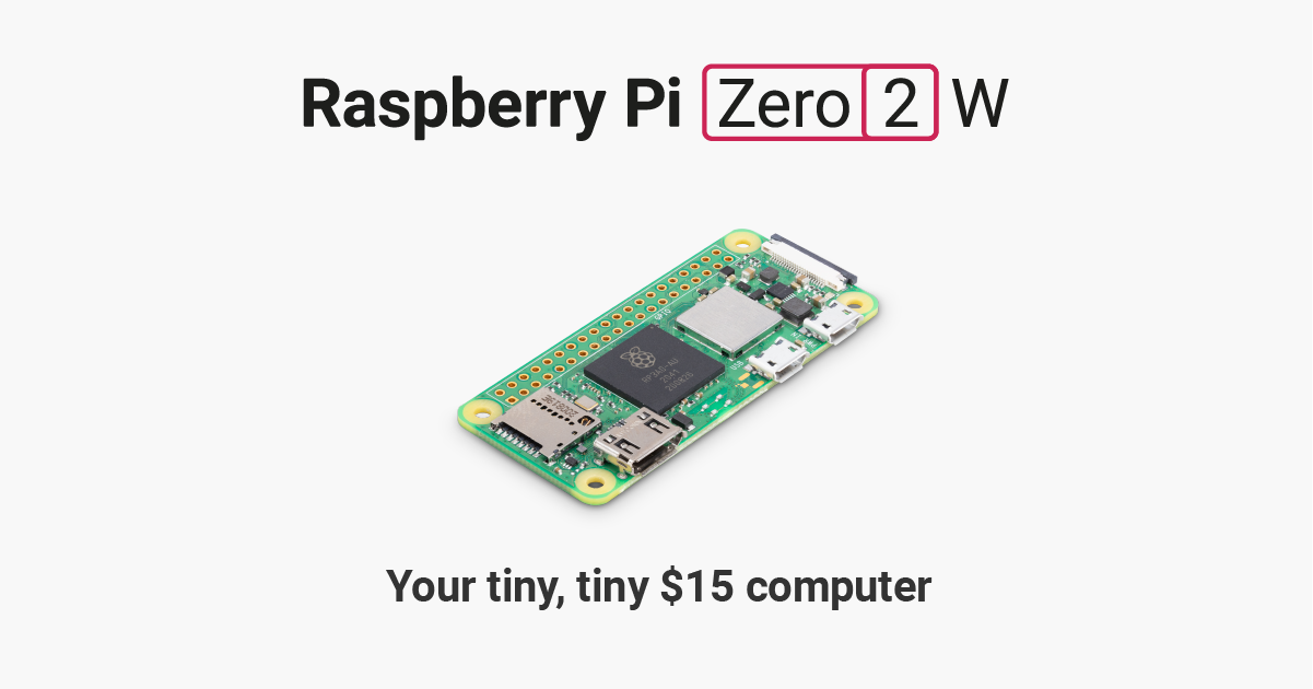
the only thing I am not sure about is whether it is compatible with the BrainCraft hat
inner seal
vivid rock
but why do you need a pico?
a raspberry pi 4 can connect to internet on its own...
huh neat, it seams I need to learn how to read beter. Anyway thanks for the help, is appreciated
muted gyro
I think that bonnet might actually theoretically work with a pi pico. Looks like it's just I2S for audio + I2C for configuration. Both are supported by the Pi Pico. I2S depends on what exact I2S format it is. And if you're using circuitpython or Arduino. I think theoretically the RP2040 can do any I2S format, in the worst case you just have to write the entire thing yourself and in the best case there's already a library for it. And for the I2C configuration there is probably no library. Might be a fun challenge.
stable forge
inner seal
huh neat, it seams I need to learn how to read beter. Anyway thanks for the help...
Voice Bonnet will work with Zero 2 W. From the guide:
Your Raspberry Pi computer is like an electronic brain - and with the Adafruit Voice Bonnet you can give it a mouth and ears as well! Featuring two microphones and two 1 Watt speaker outputs using a high quality I2S codec, this Pi add-on will work with any Raspberry Pi with a 2x20 connector - from the Pi Zero up to the Pi 4 and beyond (basically all but the very first ones made).
 lusty vault
inner seal
Ok thanks, in that case i probably need a raspberry pi to be a middleman to be a...
lusty vault
inner seal
Ok thanks, in that case i probably need a raspberry pi to be a middleman to be a...
oh good, I am not the only one to label the RAM amount specifically on the rpi ethernet port 😂
 rose echo
I'm having a lot of trouble getting my 128x64 SH1107 OLED to work with a Seeeduino Xiao SAMD21. I'm working on a DIY filament pen and this is the code but I've also tried the basic example code and it's also not worked:
If anyone could point me in the right direction I'd be appreciative; I've always had trouble getting these screens to work with arduino code and only managed to with a feather s2 running python.
vivid rock
rose echo
If anyone could point me in the right direction I'd be appreciative; I've always...
it would help you posted the actual basic example code and exact error message you are getting.
"not worked" is not very useful for debugging.
rose echo
vivid rock
it would help you posted the actual basic example code and exact error message y...
it compiles and uploads but doesn't display anything, here is the example code and resource https://learn.adafruit.com/adafruit-128x64-oled-featherwing?view=all

Adafruit Learning System
Easily add a gorgeous 128x64 OLED to your Feather project!
my encoder, stepper, feed button, and thermostatic block heating are all working with my code but nothing at all displays on the screen. I've checked connections multiple times and everything seems correct - only caveat is I don't have the RST wired but i don't really want or need it by my understanding.
vivid rock
two obvious questions:
- is it definitely SH1107?
there are many similar displays, e.g. SSD1306 - is the I2C address correct?
- do you have pullups on SDA and SCL?
can you do I2C scan and see if the address 0x3C shows up?
rose echo
- it is definitely SH1107
- the address is correct: it is written on the back of the board
- I don't think I do have pullups on them, can you help me there?
- i don't know how to do a scan, can you help me with that as well?
 vivid rock
anything from 1.8k to 10k should work.
I normally use 3.3k
as for i2scan, see e. g.
https://learn.adafruit.com/scanning-i2c-addresses/arduino

Adafruit Learning System
Hello? Are you there? Scan and find out.
rose echo
I'm finding the OLED with the pullups on the pins but I still can't draw anything
22:38:53.813 -> Scanning...
22:38:53.857 -> I2C device found at address 0x3C !
22:38:53.857 -> done
river yacht
Are there any tutorials on how to put bitmaps onto the external memory of the qualia esp32-s3 rgb666?
river yacht
I'm trying to put a 300ish kb image onto it for display, but it says it's overflowing the memory
odd heron
Hi need a help in ESP32 s3 RTC
This is my code to get the rtc and i am printing the local_time correclty. But when i access RTC inside a new tab/cpp file to print the time i am getting a different time.
rtc_esp32.cpp file
#include <Arduino.h>
#include<time.h>
#include<WiFi.h>
#include "global.h"
#include<ESP32Time.h>
#include "rtc_esp32.h"
const char* ntp_server="pool.ntp.org";
ESP32Time rtc;
void print_local_time()
{
Serial.println("inside print");
while (1){
Serial.println(rtc.getTime("%A, %B %d %Y %H:%M:%S"));
delay(1000);
}
}
void get_rtc_time()
{
Serial.println("inside Rtc function");
if(WiFi.status()==WL_CONNECTED){
Serial.println("Setting up RTC");
configTime(RAW_OFFSET, DST_OFFSET, ntp_server);
struct tm timeinfo;
if(getLocalTime(&timeinfo)){
rtc.setTimeStruct(timeinfo);
}
//print_local_time();
}
else{
Serial.println("WiFi is not connected");
}
}
Second file disp_time.cpp
#include <ESP32Time.h>
ESP32Time rtc;
while(1)
{
Serial.println(rtc.getTime("%A, %B %d %Y %H:%M:%S"));
delay(1000);
}
in the above print i am getting 1921s time.
north stream
river yacht
I'm trying to put a 300ish kb image onto it for display, but it says it's overfl...
RGB666 is 18 bits per pixel, most implementations will use 32 bits to store that, so it ends up 4 bytes per pixel, so a 300k pixel image would be well over a megabyte.
north stream
odd heron
Hi need a help in ESP32 s3 RTC
This is my code to get the rtc and i am printing ...
You may need to set the RTC. And when you set it, you need to set the year/century correctly. And you need to use the correct format character when printing the year.
odd heron
north stream
You may need to set the RTC. And when you set it, you need to set the year/cent...
i mean to say that the whole to the time is getting reset to Sep19 2021 with a random time. Using the rtc_esp32.cpp file i was able to get the right time and date.
So my concern is that if i am setting the RTC correctly.
vivid rock
rose echo
I'm finding the OLED with the pullups on the pins but I still can't draw anythin...
nothing else immediately comes to mind, sorry
rose echo
vivid rock
nothing else immediately comes to mind, sorry
Thanks for the help anyway! I'll let you know if I solve it.
rain kindle
hey all - if anyone has used the D1 R32 - can you comment on compatibility? according to the limited info out there its hardware compatible with the Uno
I just put my stack together with a clone of the Adafruit V1 Motor Shield and noticed the top two pins on each header don't get used by the shield. According to the adafruit docs, the shield is compatible with Uno and looking at the pinouts, i think it's all ok - it would appear the R1 D32 has a 5V and GPIO pin, and SCL/SDA that are not used - apart from the signal names, the power/grounds line up


however comparing to the Uno pin out - the R1 D32 has a reset pin and the Uno has AREF (3rd pin from top on the right);
the Uno on the left header, has IOREF vs the R1 D32's 5v (I guess that matches), then the R1 on the top left has an I/O, and the Uno is unlabelled
I plugged it all into a USB supply and it didn't release the magic smoke and the shields PWR LED lit up, so seems ok

 shy oasis
odd heron
So my concern is that if i am setting the RTC correctly.
shy oasis
odd heron
So my concern is that if i am setting the RTC correctly.
What I think you are saying is you have to different programs and in 1 you set the RTC from NTP and then you flash another one and try to read the time from the RTC without setting it. Since there isn't a battery backup on the ESP32 for the RTC, it won't persist if power is lost (also don't know if flashing it would clear it). From the datasheet, the RTC is kept running even in deep sleep. So I think as long as you set when you first start, then you can go into deep sleep and it should be correct when you exit deep sleep. Which makes sense since you can use a timer to exit deep sleep...
inner seal
Dose anyone know the height of a Adafruit Voice Bonnet for Raspberry Pi?
Your Raspberry Pi computer is like an electronic brain - and with the Adafruit Voice Bonnet you can give it a mouth and ears as well! Featuring two microphones and two 1 Watt speaker outputs ...
odd heron
@shy oasis my fault in not being clear. i have 3 files thats of importance the main .ino file has the following code
#include <Arduino.h>
#include <WiFi.h>
#include "wifi.h"
#include "get_ip.h"
#include "rtc_esp32.h"
#include "nimBLE.h"
#include "disp_time.h"
#include "global.h"
void setup() {
// put your setup code here, to run once:
wifisetup();
while(1)
{
Serial.println("Waiting for WIFI Connection");
delay(2000);
if(WiFi.status()==WL_CONNECTED)
{
break;
}
}
Serial.println("WIFI is connected");
get_ip();
get_offset();
get_rtc_time();
disp_loop();
}
void loop() {
// put your main code here, to run repeatedly:
}
and i have 2 cpp files rtc_esp32.cpp which has the function get_rtc_time() and disp_time.cpp which ash disp_loop()
i have already posted the code for rtc_esp32.cpp
This is the disp_time.cpp which has disp_loop() function.
#include<Arduino.h>
#include<ESP32-HUB75-MatrixPanel-I2S-DMA.h>
#include"disp_time.h"
#include <ESP32Time.h>
#include"global.h"
#define R1_PIN 11
#define G1_PIN 12
#define B1_PIN 13
#define R2_PIN 14
#define G2_PIN 15
#define B2_PIN 16
#define A_PIN 18
#define B_PIN 33
#define C_PIN 34
#define D_PIN 35
#define E_PIN 17 // required for 1/32 scan panels, like 64x64px. Any available pin would do, i.e. IO32
#define LAT_PIN 36
#define OE_PIN 38
#define CLK_PIN 37
HUB75_I2S_CFG::i2s_pins _pins={R1_PIN, G1_PIN, B1_PIN, R2_PIN, G2_PIN, B2_PIN, A_PIN, B_PIN, C_PIN, D_PIN, E_PIN, LAT_PIN, OE_PIN, CLK_PIN};
HUB75_I2S_CFG mxconfig(
64, // Module width
64, // Module height
1, // chain length
_pins // pin mapping
);
//MatrixPanel_I2S_DMA dma_display;
MatrixPanel_I2S_DMA *dma_display = nullptr;
//Setting up the color values
uint16_t myWHITE = dma_display->color565(255, 255, 255);
uint16_t myBLACK = dma_display->color565(0,0,0);
void disp_setup() {
// Display Setup
dma_display = new MatrixPanel_I2S_DMA(mxconfig);
dma_display->begin();
dma_display->setBrightness8(50); //0-255
dma_display->clearScreen();
dma_display->fillScreen(myBLACK);
// fix the screen with time
dma_display->setTextSize(1); // size 1 == 8 pixels high
dma_display->setTextWrap(true); // Don't wrap at end of line - will do ourselves
dma_display->setCursor(0, 0); // start at top left, with 8 pixel of spacing
dma_display->setTextColor(dma_display->color444(15,15,15));
while(1)
{
Serial.println(rtc.getTime("%A, %B %d %Y %H:%M:%S"));
delay(1000);
}
while(1)
{
String time= rtc.getTime("%H:%M:%S");
dma_display->println(time);
delay(500);
}
}
void disp_loop() {
Serial.println("Inside Disp loop");
disp_setup();
}
when i print the time inside the rtc_esp32.cpp file i get the correct local time. but when i display the time inside the disp_time.cpp i am getting a different time.
shy oasis
odd heron
when i print the time inside the rtc_esp32.cpp file i get the correct local time...
So in global.h you have "extern ESP32Time rtc;"?
odd heron
shy oasis
So in global.h you have "extern ESP32Time rtc;"?
i didnt try that.
i had it inside the rtc_eps32.cpp.
odd heron
@shy oasis @north stream ..thanks for the help and suggestion. I have solved the issue
river yacht
north stream
RGB666 is 18 bits per pixel, most implementations will use 32 bits to store that...
The binary for it was ~300kb, but I've got the Qualia ESP32-S3. It has 16mb of flash and 8 mb of ram, but the progmem is ~300kb available total and the dynamic memory seems to be even less... so there has got to be a way to add the image to the flash and load it into ram?
north stream
river yacht
The binary for it was ~300kb, but I've got the Qualia ESP32-S3. It has 16mb of ...
There probably is. I think there is some sort of flash file system support. It may be that you have to load the image into RAM and to the display a chunk at a time, I don't know.
river yacht
My google foo has been insufficent to find an answer and chat gtp gets confused...
north stream
Unfortunately, I don't know much about that chip. Hopefully someone else here will.
stark kindle
river yacht
My google foo has been insufficent to find an answer and chat gtp gets confused....
I was going to reply earlier but wanted to double check.
PSRAM should be available when you call malloc() in an Arduino program on an ESP32-S3 that has PSRAM. So you should be able to malloc(300000) successfully. I just ran a test that allocated 500K with no problem.
Are you sure you've selected the correct board in the Arduino IDE? If you select an S3 that has no PSRAM I don't think it will detect the extra RAM and use it.
You can try this program to confirm that it sees the PSRAM:
#include <Arduino.h>
#include <Esp.h>

void setup() {
  Serial.begin(115200);
  delay(2000);
  Serial.print("psram? ");
  Serial.println(psramFound());

  Serial.print("available memory ");
  Serial.println(ESP.getHeapSize());
  Serial.print("psram size ");
  Serial.println(ESP.getPsramSize());
}

void loop() {
}```The getHeapSize() method will only report on built-in memory, that won't include PSRAM.
river yacht
i did check the psram size and it was just shy of 8mb. Though I still need to store the image somewhere, so somehow I have to add it to the 16mb flash? sorry if this seems like a dumb question!
stark kindle
It's not a dumb question. There's a filesystem in the flash, you should be able to store it there and then read it into RAM when you need to use it. It's possible there may be helpers for the display you'll use that can display directly from a file, I can't say for sure.
 lethal yacht
hey, i am a bit new with building circuits so if it sounds like i have no idea what im saying please point it out because you are probably right. i have the BNO08x that i am trying to use, is it possible to use the IMU without using the library? im trying to use a regular arduino uno(ideally it would be a nano but im prototyping still) and the library takes up too much memory for the board. is it possible to just not use that library and write my own code? i wanted to make sure that its possible before i attempt to do it
leaden walrus
the BNO08x is complex, so the supporting libraries will end up being fairly large
for using with the UNO, the RVC of the BNO08x might help?
 shell folio
Hi! This is my first time odd this discord group and I’m sorry if I sound my rude.
I want to ask you about using air pump with Arduino. Now I think about purchasing “air pump and vacuum DC moter(https://www.adafruit.com/product/4699 )”.Can I use this using Arduino? or only with the circuit series? Could you please let me know if there is a website or other reference to use for this! Thank you.
Make inflatables or air-powered projects with this simple air pump. It's great for beginner projects and super easy to use! The pump is basically a DC motor that is powered with ~4.5V ...
vivid rock
shell folio
Hi! This is my first time odd this discord group and I’m sorry if I sound my rud...
Arduino (or any other microcontroller board) by itself can only provide tiny current from each of its pins - not enough to power the
pump.
So you need an arduino-like board + a motor driver (which amplifies the current). For example, one of Adafruit feather boards + motor "wing" (feather add-on board).
or you can buy a board like this, which combines microcontroller (rp2040) and motor driver IC on one board:
https://www.cytron.io/amp-p-maker-pi-rp2040-simplifying-robotics-with-raspberry-pi-rp2040

Cytron Technologies
Simplifying Robotics with Raspberry Pi® RP2040Cytron Maker Pi RP2040 features the first microcontroller designed by Raspberry Pi - RP2040, embedded on a robot controller board. This board comes with dual channel DC motor driver, 4 servo motor ports and 7 Grove I/O connectors, ready for your next
 random lion
Hey I am on a student atv building team who designed a teensy based data logger. We wanted to add a lcd screen to our car and found this one on digikey https://www.seeedstudio.com/WT32-4-3-Inch-Display-p-5543.html
It says it uses an rgb interface and we know it works with some version of their proprietary chinese gui designer. The driver is the st7701 as stated in the datasheet. We would really like to use the GFX library with it if anyone has any info on using the st7701 with the gfx library that would be very helpful.
Some more info is that this is the pinout we have found in the datasheet. We dont understand why the rgb lines are in such random amounts (4r 7g 5b) we think this is due to it only being a 480x272 screen instead of 480x480. As well as the fact that it does not seem like it uses SPI while every other resource we have found on the st7701 seems to use spi. Do we need to make our own screen type declarations in the gfx library? We just dont really know.
Lastly we did see that https://www.adafruit.com/product/5792 this adafruit product uses the st7701s driver so maybe we can use something from that.


WT32 4.3 Inch Display is a standard serial port LCD screen, Based on ESP32-S3 and core efficient development platform 8ms(8MS.XYZ), which can quickly help products to complete the application of networking + color screen upgrade.

This is a screen for advanced hackers who like the look of a nice, round TFT screen with tons of pixels. The 2.1" diagonal sized display has 480x480 16-bit full-color pixels and is ...
Pinout
 shell folio
vivid rock
or you can buy a board like this, which combines microcontroller (rp2040) and mo...
shell folio
vivid rock
or you can buy a board like this, which combines microcontroller (rp2040) and mo...
I see. Thank you so much for your help!!! I would consider purchasing this boat.
north stream
random lion
Hey I am on a student atv building team who designed a teensy based data logger...
The RGB lines are distributed like that for color fidelity, not size. Since the human eye is more sensitive to green, it has higher resolution (7 bits) that red or blue. The total was chosen to add up to a nice round 16 bits so supporting hardware can store a pixel in a 16-bit value.
random lion
That makes sense
random lion
Any good resources on setting up the gfx library
odd heron
i am using Adafruit_gfx_library and there are some fonts available in the fonts folder. However i want use other types of fonts that are not availabel default in the lib. is there any other utility that can convert ttf to c header file fonts ?
north stream
native dagger
I want to use this library (https://github.com/mathertel/Dmxserial) but it only supports boards like this one (https://www.electromaker.io/shop/product/beetle-cm-32u4-compatible-with-arduino-leonardo-atmega32u4), is it wild to use one of these to just take in dmx signals communicate with a more advanced board ?

GitHub
An Arduino library for sending and receiving DMX packets. - GitHub - mathertel/DMXSerial: An Arduino library for sending and receiving DMX packets.
 quartz furnace
Got a new ESP32-C6 capable of doing Zigbee protocol
I don’t see any starter examples in the Arduino IDE , anyone have a guide ? Or is just the standard Zigbee library?
north stream
native dagger
I want to use this library (https://github.com/mathertel/Dmxserial) but it only ...
It's reasonable to use a small MCU like that as a signal translator to talk to something else. I've done stuff like that.
 crimson kraken
Hello, I'm using the raspberry pi pico and I'm trying to use the adafrut HC-SR04 ultrasonic distance sensor. I am getting just random measurements from 0 to 2000 (and seemingly any random value in between.) while the sensor is facing a wall not moving. I can't detect a pattern. I removed the triggering logic and just printed out the high/low of the echo pin and it rapidly flips back and forth. Has anyone else seen this? I started with using this style shown in this tutorial https://dev.to/apollolabsbin/embedded-rust-and-embassy-timer-ultrasonic-distance-measurement-31mj but in debugging have landed here but with basically identical results. Could someone help me possibly see what I am missing? Here is my code https://gist.github.com/rust-play/42dfdeb1d284dfe3cb44b2013634a92c

DEV Community
This blog post is the fifth of a multi-part series of posts where I explore various peripherals in...

Gist
Code shared from the Rust Playground. GitHub Gist: instantly share code, notes, and snippets.
inland gorge
crimson kraken
Hello, I'm using the raspberry pi pico and I'm trying to use the adafrut HC-SR04...
You may not get many responses in this channel as it’s for Arduino and not many folks here know Rust
crimson kraken
Yeah I understand. The question in my mind isn't focused on the Rust as much as why would the echo io be flipping high/low without a trigger. I would think that issue is language agnostic.
It happens even when the pico isn't connected to the ultrasonic sensor.
inland gorge
crimson kraken
Yeah I understand. The question in my mind isn't focused on the Rust as much as ...
Ah, okay. Is it exactly that Seeed Grove sensor or some random similar ultrasonic sensor? I ask because most of the random sensors only work at 5V (designed for original 5V Arduino boards) and the Seeed sensor is designed to work at the 3.3V used by the Pico.
oh no wait you said you're using the Adafruit part. You should wire it up like in the Learn Guide for that part then https://learn.adafruit.com/ultrasonic-sonar-distance-sensors/python-circuitpython
 merry drum

 proven hound
Hey all, I hope this is the correct channel to ask in, but I have a brand new Feather M0 w/RFM69 module on it, and it's stuck in bootloader mode doing some strange things. When I try to access the D: drive it hangs Windows Explorer, when in bootloader mode (double clicking the reset) it shows the bootloader files but doesn't let me open the .txt or copy over a new bootloader. I have tried multiple USB cables (known good) and different USB ports. I've also tried closing down any USB related apps like Corsair iCue and Steelseries GG in hopes they were somehow conflicting. Any help here would be greatly appreciated.
proven hound
I figured it out, Arduino IDE v2.2.1 has some apparent major issue with the Feather M0 boards, it nearly bricked mine. Reverting to 1.8.19 everthing works perfectly. Although I'm struggling to get the RFM69 module to initialize. Atleast it works now, sorta.
viral prawn
Yo dudes I'm trying to wire Ethernet up to my ESP32-S2 dev kit using one of these https://www.amazon.com/gp/aw/d/B0B6G27DC1?psc=1&ref=ppx_pop_mob_b_asin_title but I can't find the proper way to wire it up

Features High-Performance 10/100 Ethernet Physical Layer Transceiver (PHY) Supports single 3.3V supply Supports the reduced pin count RMII interface Supports HP Auto-MDIX Onboard chip package: 24-pin QFN (4x4 mm) Lead-Free RoHS Compliant package Flexible Power Management Architecture Integrated 1...
I'm trying to use eth.h and everyone seems to just define two pins in code. What do I do with all the other pins? Also I don't want poe
viral prawn
Also some people were saying they needed to flash new firmware. Is that applicable still?
stark kindle
viral prawn
Also some people were saying they needed to flash new firmware. Is that applicab...
Flash what new firmware? Your firmware will have to be built supporting Ethernet, firmware built without support for it won’t just start working with it.
viral prawn
Is there documentation for this?
stark kindle
I believe the ESP32-S2 only supports Ethernet via SPI. This looks like an Ethernet PHY module - basically a transceiver. It might work with a regular ESP32 but I don’t think it’s compatible with the S2, which doesn’t have Ethernet PHY support, sorry.
stark kindle
viral prawn
Is there documentation for this?
There is in ESP-IDF, and some for Arduino. Web search should find it.
 frail pawn
A conundrum, Is there any reason I couldnt use a HUZZAH32 with the DC motor feathering AND a PCA9685?
leaden walrus
in general no. just make sure the PCA's have unique I2C addresses.
frail pawn
jumped the last line of pads which should m ake ot 0x41 i think?
is the power LED on the PCA9685 MEANT to flash..
 vale mauve
Hey, my friend wanted to get into embedded programming. I don't feel qualified to give him a strong recommendation. What do you recommend he gets? (He already has an arduino but that's it)
Though I did recommend, a basic robotic arm might be a good starter project. (He has a CNC machine, basic programming knowledge but I have a good amount so I can help him there)
So maybe a soldering iron kit or something could be good?
charred salmon
frail pawn
is the power LED on the PCA9685 MEANT to flash..
Judging by the schematic, no. This section appears to be the IO header, and shows that the LED is between VCC and ground by way of a single resistor.

 livid osprey
Is your VCC pin wired to your power source?
frail pawn
PWM motor shield
the feather thing
oh wait, i might hav ehad the VCC hooked to the wrong thing for the last 4 hours
let me check
big brighty healthy red glow on the power LED
amazed i didnt let any magic smoke out
thankyou lollbomb, if you hadnt mentioned the LED being tied to VCC i probably would have been stuck even longer
leaden walrus
you have one of these?
https://www.adafruit.com/product/2927
frail pawn
yep thats the badger, it seems to be working now, just had VCC hooked uip to er...IO17 by accident
leaden walrus
but you mention another PCA9685 being used as well?
frail pawn
yes, i had accidently hooked up io17 from the huzzah32 into the PCA9685
the servo is at least moving now so i think i am getting there
frail pawn
its the 16 channel servo/LED driver thing
leaden walrus
one of these?
https://www.adafruit.com/product/815
frail pawn
thats the one, they seem to work happily together now
just gotta work out how the servo library works now, only used the circuitpython one before which is v simple
leaden walrus
sounds like the mainboard is not a feather? the "HUZZAH32"?
 frail pawn
i am, the wing passes through the pins so ive tapped them off for the PCA9685

It's a little ugly rn
leaden walrus
the VCC pin issue was on the PCA breakout?
the feather and wing should just mate pin-to-pin without any issue
frail pawn
simply a mistake on my part, i though it was first pin from the right in that image, it was in fact first on the left
the red wire on the mated stack was on the wrong pin, just me getting left and right mixed up 🙂
leaden walrus
ah. ok. that makes sense.
wasn't sure if it was a feather/featherwing issue or elsewhere
it was elsewhere - on the breakout
frail pawn
nah, old school PEBKAC
problem exists between keyboard and chair 😄
now to work out how the servo library works, ty for the help!
leaden walrus
yah, no worries. we all do those.
be mindful of this pin as well, since it has the motor power exposed
 frail pawn
right, ill make sure nto to wire that up wrong haha
charred salmon
frail pawn
It's a little ugly rn
All projects go through that phase. My tabletop counter currently has a veritable afro of wires, some of which are redundant because I didn't want to alter the original wiring that I knew worked while also switching from a Trinket M0 to standalone ATTiny85.
grave mortar
kind of a weird question but I picked up an uno second hand only to get home and realize that I'm now worried that the person could have uploaded malicious code. Any advice is appreciated.
 rough torrent
A plain Arduino Uno R3 (ex. no WiFi or BT module) will probably not be malicious, as long as the hardware wasn't modified
The only possibility I can think of is that they uploaded custom firmware to the USB to serial chip and then it will act as a bad USB
charred salmon
Judging by the version I have, doing that wouldn't be hard per se. The USB chip is just another ATMega, but QFN package (I think). The ICSP header for it is right there.
That said, you'd have to consider "why?" What purpose could someone possibly have to do that?
If you're particularly paranoid, and have the ability to program over ICSP, you could in theory reflash both chips with their respective manufacturer loadouts.
grave mortar
true true kk I'll think it over, I really wish I could just program a attiny85 with my pi pico
north stream
You should be able to do so: the programming protocol is fairly simple. It's easy enough to program one with an ordinary Arduino.
 charred grove
Guys i really need some help with my project. I’m implementing duplex communication via mqtt. But .onMessage() function is not getting called at all.
Please if someone can take out a couple mins and review my code, I’ll be v thankful.🙏🏻🙏🏻
Here’s the link (single .ino file)
https://github.com/moizghumann/IoT_Temperature_Control/blob/main/sketch_dec3c.ino
GitHub
Contribute to moizghumann/IoT_Temperature_Control development by creating an account on GitHub.
 finite wind
Hello guys I am doing a college project for my Embedded Systems Class. We are using an B-L475E-IOT01A board and STM Cube IDE. I am using the Paho MQTT library for subscribing and publishing to Adafruit IO (free account). My teacher provided us with the project template. The problem I have is that I cant subscribe to more than 5 topics using the STM microcontroller. It can be any 5 topics, but the 6th and the following always fail instantly. If I use an online MQTT client such as MQTT.cool I can subscribe to all the topics and it works perfectly. I am attaching the main.c from my project. If I use "g00409592/feeds/#" I subscribe to all feeds and that works. But I then get a JSON, csv and other formats of responses that I dont really need.
This is the section where I try to subscribe
ret = MQTTSubscribe(&client, "g00409592/feeds/00", QOS1, (subscribeMessageHandler));
    if (ret != MQSUCCESS) {
        printf("\n\rSubscribe failed: %ld\r\n", ret);
    }
    else {
        printf("\n\rSubscribed to 00\n\r");
        ret = MQTTYield(&client, 2500);
    }

    ret = MQTTSubscribe(&client, "g00409592/feeds/01", QOS1, (subscribeMessageHandler));
    if (ret != MQSUCCESS) {
        printf("\n\rSubscribe failed: %ld\r\n", ret);
    }
    else {
        printf("\n\rSubscribed to 01\n\r");
        ret = MQTTYield(&client, 2500);
    }

    ret = MQTTSubscribe(&client, "g00409592/feeds/02", QOS1, (subscribeMessageHandler));
    if (ret != MQSUCCESS) {
        printf("\n\rSubscribe failed: %ld\r\n", ret);
    }
    else {
        printf("\n\rSubscribed to 02\n\r");
        ret = MQTTYield(&client, 2500);
    }

    ret = MQTTSubscribe(&client, "g00409592/feeds/10", QOS1, (subscribeMessageHandler));
    if (ret != MQSUCCESS) {
        printf("\n\rSubscribe failed: %ld\r\n", ret);
    }
    else {
        printf("\n\rSubscribed to 10\n\r");
        ret = MQTTYield(&client, 2500);
    }

    ret = MQTTSubscribe(&client, "g00409592/feeds/11", QOS1, (subscribeMessageHandler));
    if (ret != MQSUCCESS) {
        printf("\n\rSubscribe failed: %ld\r\n", ret);
    }
    else {
        printf("\n\rSubscribed to 11\n\r");
        ret = MQTTYield(&client, 2500);
    }

    ret = MQTTSubscribe(&client, "g00409592/feeds/12", QOS1, (subscribeMessageHandler));
    if (ret != MQSUCCESS) {
        printf("\n\rSubscribe failed: %ld\r\n", ret);
    }
    else {
        printf("\n\rSubscribed to 12\n\r");
        ret = MQTTYield(&client, 2500);
    }
Anyone have any experience listening to their automotive can-bus with the can m4 feather?
odd heron
Hi can anyone help me in understanding the inner if statement in following code
if(WiFi.status()==WL_CONNECTED)
{
Serial.println("Setting up RTC");
//Getting the time based on RAW Offset and DT Offset
configTime(19800, 0, ntp_server);
struct tm timeinfo;
if(getLocalTime(&timeinfo))
{
Serial.println("inside the if statement");
rtc.setTimeStruct(timeinfo);
}
//print_local_time(); Printing RTC for testing purpose.
Serial.println("get_rtc_status function executed");
Serial.println("RTC timer set");
Serial.println(rtc.getTime("%A, %B %d %Y %H:%M:%S"));
return rtc_status=true;
}
 odd fjord
odd heron
Hi can anyone help me in understanding the inner if statement in following code ...
odd fjord
odd heron
Hi can anyone help me in understanding the inner if statement in following code ...
If getLocalTime(@timeinfo) returns a non zero value then the result will be used to set the rtc. If the getLocalTime call fails, it will return a 0 (false). https://github.com/espressif/arduino-esp32/blob/master/cores/esp32/esp32-hal-time.c#L95 The code continues on to return rtc_status= true regardless of the previous result. This is prbably not what you want.
 opal iris
Hello all,
I am working with HC 05 Bluetooth module but I am not able to connect it to my laptop. In device manager, I am able to see com ports. But not able to connect.
grave mortar
god I'm so close using TinywireS I can write back a multibyte response but I need to write back 45 hex values and my attiny85 locks up when I do like 10 or more. I can't figure out what to searchto fix this.
 grave mortar
ah okay so I've found that 'm not supposed to send more than 1 byte but can't for the life of me figure out how to send a 90 byte reply 😦
frail pawn
a random google suggests tinywire has a maximum 16byte buffer
idk if this will help at all
but yoiu could try
#define TWI_RX_BUFFER_SIZE ( 128 )
#define TWI_TX_BUFFER_SIZE ( 128 )
#include <TinyWireS.h>
but i will caveat this with i have no experience with the library itself and this is simply a comment i found on github
grave mortar
frail pawn
a random google suggests tinywire has a maximum 16byte buffer
Thanks, after some extensive digging it seems like the sequential read in Rambo's Tinywire isn't working correctly https://github.com/rambo/TinyWire/issues/36 it looks like you're supposed to be able to put everything into the array and it should work. I'm going to try this older version to see if it's pre-code break https://github.com/svoisen/TinyWire/tree/master/TinyWireS
frail pawn
Gl!
grave mortar
frail pawn
Gl!
nice yeah the older library works now I just can't figure out how to make the wire library read more than 32 bytes ahah'
frail pawn
just out of interest what are you communicating between
grave mortar
currently an uno and an attiny85, the 85 is to emulate a battery gas gauge on another device, so I think I'll actually be okay because that i2c host shouldn't crap out like the uno
frail pawn
ah right, i was going to say one of the bits of adbvice ive been given befire is dont use i2c between two microcontrollers
but i guess that doesnt apply
grave mortar
yeah I think I'm good now hopefully I can run the 85 at 1.8v but if bot I'll just level shift
frail pawn
i only looked into this because the little rover ive been building has an esp32 and a pi0 and i was considering making them talk to each other
grave mortar
what would they talk about
frail pawn
and someone was like "ppf use uart fool"
well rnh the pi0 literally just transmit video from the onboard camera, the esp32 controls the motors and servos, if they talk i can control the rover from a web interface as well as send feedback of certain sensros and such to the video stream
there is a very simple pan tilt for the camera with servos but there is no indication of where the servos currently are so it can get disorentation, you try to dry the rover forward but turns out WOOPS you have the pan head 10 degrees to the left so it doesnt drive straight
grave mortar
lol nice that's sick
uart is good if it's available and reliable but i2c is pretty cool
frail pawn
im using i2c for the servos and motors so that was my first idea
the problem is now i have it together and working the ADHD bit of my brain is like "you no longer care about this"
 vague inlet
excuse the terrible drawing

I was wondering if anyone knows the best way to go about this, I want to use an arduino to control a motor (I was thinking stepper) to pull a weight of about 2.5 kg from and too a specific height. the motor would roll up and lower a chain or rope that is attached to the object, so I dont think the chain or rope will move too far away from drive shaft. I did just try it with a nema 17 and a a2988 board but from my tests its seems really weak.
was thinking about swithcing to nema with planetary gear reduction https://www.omc-stepperonline.com/nema-17-stepper-motor-bipolar-l-48mm-w-gear-ratio-27-1-planetary-gearbox-17hs19-1684s-pg27 like this one
frail pawn
you need to calculate the torque required, which is based on the weight of the load and the width of the pulley and stuff, im not an expert, you can probably find a calculator online
 granite pecan
Hi, I am looking the BMP3XX example code and struggle to understand it. I want to use it at RPi Pico which has 2 I2C ports (Wire and Wire1). Where is the Wire.begin() code? https://learn.adafruit.com/adafruit-bmp388-bmp390-bmp3xx/arduino

Adafruit Learning System
The BMP3xx has better precision than ever, which makes it excellent for environmental sensing or as a precision altimeter. It can be used in either I2C and SPI configurations.
Is it written in the included codes or something?
quartz furnace
https://github.com/gabrielchristino/ANCS/blob/main/ANCS.ino
This is a neat library that allows you to connect a ESP32 with Bluetooth to your iOS device to get the notifications (ANCS)
It works perfectly and prints messages with serial print
It’s either getting the data as individual strings or as a single data dump
I’m having a problem finding where the “message” of the notification is — example if it’s a WYZE Camera notification— what the message was from WYZE
This

GitHub
Projeto para ESP32 suportar as notificações do iPhone, usando ANCS - gabrielchristino/ANCS
What I’m looking to do is find the actual “message” and be able to print it to a TFT
I’ve gone on my laptop and did a “find” for the usage of “Serial.print”
I looked at all 37 and it’s not clear how they name the storage of the notification

Above shows the print outs
I’ve only been able to find how it’s prints the “ category” based on a “case statement”
374 lines of code — with a .cpp file and a .h file as well. I just can’t determine the data type message is stored to be able to update a TFT display
frail pawn
You could contact the creator?
quartz furnace
I might have to do just that —- but it would have to be somewhere within the code ?
unless if they’re doing some kind of secret code magic
frail pawn
oh its in there, but if you can get an answer from the person who wrote it its going to be much easier than hoping someone with the knowledge has half an hour to trawl through it 😛
 unreal monolith
OK, figures all I had to do was post and I'd find the answer!
With my last ESP32 board I didn't want to reset the board when I connected the serial terminal so I made the default state of DTR/RTS as OFF. Turns out that for some reason either CP or the ESP32-S2 needs DTR ON in order for the serial terminal to work.
Now I'm curious if this is a CP thing or something with the ESP32-S2. I know for sure that with a ESP32 I can have DTR OFF and communication works just fine but of course that's not going through USB like I'm currently connected.
 dusk orchid
granite pecan
Hi, I am looking the BMP3XX example code and struggle to understand it. I want t...
dusk orchid
granite pecan
Hi, I am looking the BMP3XX example code and struggle to understand it. I want t...
Wire.begin has usually been called for you. Sadly the learn guide doesn't show the call to begin, but it does link you to the driver repo on GitHub. There you can see in the header file the driver takes an argument for a wire object here https://github.com/adafruit/Adafruit_BMP3XX/blob/master/Adafruit_BMP3XX.h#L45-L46 then in the cpp file in same repo https://github.com/adafruit/Adafruit_BMP3XX/blob/master/Adafruit_BMP3XX.cpp#L83-L86 it relies on an Adafruit BusIO (mentioned in library.properties file) object called Adafruit_I2cDevice which starts the wire device here https://github.com/adafruit/Adafruit_BusIO/blob/master/Adafruit_I2CDevice.cpp#L31
fallow valve
how I two program shift regs to control a 20 led bar segment? since two can control 10 leds
dusk orchid
fallow valve
how I two program shift regs to control a 20 led bar segment? since two can cont...
Have an LED control function that switches the output of the correct shift register based on requested LED number <10
fallow valve
Working with 20 is the harder thing to do
 west quarry
I am using an Arduino to get data from various sensors (e.g. temp, humidity, pressure, etc)
I have the Arduino connected to a rpi which will read the serial data and send it to a DB.
My question is what is the best data format? Should I send all sensor data at once, or each sensor value independently?
Any help would be great! (please ping me)
leaden walrus
how are you talking between the arduino and the pi? serial?
west quarry
leaden walrus
how are you talking between the arduino and the pi? serial?
Yes, I haven't tested it yet, but I think the RX and TX pins on both the Arduino and Pi work just the same as plugging the arduino into the pi? (using a zero, so want to avoid using a usb cable)
leaden walrus
yep. uno is 5V.
pi's are 3.3V logic. so might need to level shift to wire direct.
but in terms of when/what to send, should be fine to send everything at once.
sort of depends on your use case
could just send a json string with the data in it
that'd make parsing on the pi side easy
west quarry
Gotcha, that would work, yeah
can the RX/TX pins be used for sending this kind of data? or am I totally wrong? 😅
west quarry
A couple of them are, but some are just analog
I got a handful of sensors to try out, my current plan is to get them all working and since there's crossover, see which ones are more accurate/reliable
leaden walrus
could also maybe read the sensors directly from the pi?
would need to get an ADC for the analog sensors
but there are numerous I2C based ADCs available
unless there are sensors that have really specific hard timing requirements that make using the UNO necessary
west quarry
These are the sensors in questions
https://thepihut.com/products/adafruit-stemma-soil-sensor-i2c-capacitive-moisture-sensor-ada4026
https://thepihut.com/products/capacitive-soil-moisture-sensor
https://thepihut.com/products/dht22-temperature-humidity-sensor
https://thepihut.com/products/adafruit-bh1750-light-sensor-stemma-qt-qwiic
https://thepihut.com/products/adafruit-dps310-precision-barometric-pressure-altitude-sensor
https://thepihut.com/products/bme280-breakout-temperature-pressure-humidity-sensor
Currently I have the DHT-22 and the BME280 ready to use - I haven't soldered or tried out the rest yet
leaden walrus
the DHT-22 will be the most finicky device in the lot
https://learn.adafruit.com/modern-replacements-for-dht11-dht22-sensors/overview
other than the one soil sensor, the rest are I2C
since it would make things simple, might be worth considering getting everything hosted on the pi
west quarry
Would the pi zero be able to handle all of these sensors at once?
leaden walrus
no pi would be happy with the DHT-22
and pi's don't have ADC, so no way to read the one soil sensor without one
but a pi would have no issues reading a half dozen I2C sensors
pi's have native I2C (in case that wasn't clear)
west quarry
Gotcha. The other sensors also handle what the DHT-22 does, so not a big deal
part of the reason why I got overlap in the first place (mainly because I was worried I'd screw up soldering somewhere)
leaden walrus
for that, could utilize the STEMMA QT connectors as much as possible

that connector is for I2C. full details here:
https://learn.adafruit.com/introducing-adafruit-stemma-qt/what-is-stemma
there are lots of cable options:
https://www.adafruit.com/category/619
west quarry
awesome, thanks for your help!
west quarry
I did actually pick up a few of these cables at the same time. A bunch of 4 pin ones
Seem to be way too big though. I guess there are other variants
lusty vault
way too big? 
west quarry
Same connectors used by the DHT-22 - I guess they are not the same type of connector. Pretty sure they are needed for one of the soil sensors. I can't find the sensors right not to check.
leaden walrus
the DHT-22 is not i2c. it's its own thing.
west quarry
Both soil moisture sensors have that connector - I guess I need to get those I2c small cables!
west quarry
I may just solder them instead. At least for the board sensors.
leaden walrus
the i2c cables will do nothing to help with the DHT-22
 desert bough
hello, very much a noob with the more technical part of electronics and am hesitant to dip my toes in for fear of breaking something. recently i began a project which will require me to make a switching voltage regulator circuit with a MOSFET and some other components to provide 5V down from a 12V supply (relatively high load - many neopixels being driven off of one regulator). However, I know switching regulators can be very noisy, at least compared with linear regulators, and was worrying about how a microcontroller might react to a noisy power feed. would a normal mcu, like the metro mini, do ok with that? what inductor and capacitor do i pick for the switching circuit to minimize noise?
leaden walrus
there are ready made products for dealing with converting 12V to 5V. but it sounds like you need to design your own?
 lethal yarrow
I would recommend powering the MCU off the 12V source as the energy loss will be minimal. Leave the big switching regulator to power the LEDs.
Assuming you are ok with using a prebuilt switching regulator module, I recommend getting a mean well DC-DC converter. While there are chips that make switching regulator design relatively easy, there are still some design complexities that are best avoided when possible.
native dagger
Is accel stepper compatible with the rp 2040 or samd21?
I can't find a straight answer.
lethal yarrow
Looking at the source code, I don't see anything that is architecture-dependent. That being said I would consider its implementation to be... suboptimal. It tries to implement the timing purely in software with calls to micros(), which can result in a lot of jitter if you are doing other things and don't call the runStepper() function fast enough.
https://github.com/waspinator/AccelStepper/blob/master/src/AccelStepper.cpp

GitHub
Fork of AccelStepper. Contribute to waspinator/AccelStepper development by creating an account on GitHub.
native dagger
How would you characterize fast enough?
native dagger
lethal yarrow
Looking at the source code, I don't see anything that is architecture-dependent....
Any other options you'd consider?
lethal yarrow
Depends on your requirements. I would probably use a stepper driver though.
native dagger
I am using a stepper driver, this library allows for that. Driver takes just step enable and direction. All I need is to spin a stepper and read a pin
lethal yarrow
Then just use it I guess, unless you're needing much more precise realtime control.
 sacred lake
hello, i have an arduino nano with just a potentiometer hooked up and the little "TX" light is flickering and it randomly freezes. this is my just my current code:
void setup() {
  Serial.begin(9600);
}

void loop() {
  int analogValue = analogRead(A0);
  float percentage = (float) analogValue / 1023 * 100;
  int roundedPercentage = (int) floor(percentage);
  String output = String(roundedPercentage);

  Serial.println(output + "%");
  delay(50);
}```ive tried 100ms of delay but its still happening
stable forge
sacred lake
hello, i have an arduino nano with just a potentiometer hooked up and the little...
i believe the String library can generate garbage and eventually you will run out of RAM. Try this instead:
  int roundedPercentage = (int) floor(percentage);

  Serial.print(roundedPercentage);
  Serial.println("%");
  delay(50);
that seems to have fixed it. one more thing:
i'm on linux and everytime i re-plug the arduino, i get a permission denied error on /dev/ttyUSB0 and have to run sudo chmod a+rw /dev/ttyUSB0. i've created the dialout group and added myself but that didnt change anything
stable forge
sacred lake
that seems to have fixed it. one more thing:
i'm on linux and everytime i re-plu...
which Linux are you using?
Did you reboot after adding the dialout group and adding yourself? Just logging out from the desktop and logging yourself back might not add yourself to the group immediately.
sacred lake
stable forge
which Linux are you using?
Did you reboot after adding the dialout group and add...
im using archlinux (btw) and have rebooted, it didnt work
stable forge
sacred lake
im using archlinux (btw) and have rebooted, it didnt work
do you have modemmanager installed/running?
remove that package, it's not really useful these days
sacred lake
i just removed it
 coarse prism
Hello, I am trying to use the Adafruit Pygamer with Arcada utilizing PlatformIO as the dev environment. I can compile and upload Arcada examples to the Pygamer and everything works except the display. The same code compiles, uploads and works fine with the Arduino IDE.
I found this issue: https://github.com/adafruit/Adafruit_Arcada/issues/44 which seems to be related to what I'm experiencing.
Anyone got a clue how I can get going? All the device's bells and whistle work, just it seems drawing commands are broken when compiled with PlatformIO.
I uploaded my PlatformIO project, but it's not much more than an Arcada example, https://github.com/dustinlacewell/arduino-pong
inland gorge
coarse prism
Hello, I am trying to use the Adafruit Pygamer with Arcada utilizing PlatformIO ...
Did you try the workarounds described in this comment to that issue? https://github.com/adafruit/Adafruit_Arcada/issues/44#issuecomment-1067317712
coarse prism
Yeah I did. Actually the latest versions have some new code to check if you're using those boards and automatically ifdef them out. But I commented it out anyway, Still doesn't work.
It seems like the board doesn't hang when the drawing routines are called, but they don't seem to do anything. When any program I write boots up I just get a white screen. LEDs, gyro, speaker, buttons, etc all work. Just no drawing commands make it to the screen.
coarse prism
I'm probably stuck with circuitpython
I've tried everything for hours
I tried to boil it down to just the display:
#include <SPI.h>
#include <Adafruit_ST7789.h>

#define ARCADA_TFT_SPI SPI1
#define ARCADA_TFT_CS 44  // Display CS Arduino pin number
#define ARCADA_TFT_DC 45  // Display D/C Arduino pin number
#define ARCADA_TFT_RST 46 // Display reset Arduino pin number
#define ARCADA_TFT_LITE 47
#define ARCADA_TFT_ROTATION 3
#define ARCADA_TFT_DEFAULTFILL 0xFFFF
#define ARCADA_TFT_WIDTH 320
#define ARCADA_TFT_HEIGHT 240

Adafruit_ST7789 *tft;

void setup() {
  // put your setup code here, to run once:
    new Adafruit_ST7789(&ARCADA_TFT_SPI, ARCADA_TFT_CS, ARCADA_TFT_DC, ARCADA_TFT_RST);

    tft->init(240, 320);
    tft->setRotation(ARCADA_TFT_ROTATION);
    tft->fillScreen(ARCADA_TFT_DEFAULTFILL);
}

void loop() {
  // put your main code here, to run repeatedly:
  tft->fillScreen(0xFF00);
  delay(100);
  tft->fillScreen(0x00F0);
  delay(100);
  tft->fillScreen(0x000F);
  delay(100);
  tft->fillScreen(0x0000);
  delay(100);
}
Still nothing 😩
fallow valve
https://learn.adafruit.com/adafruit-audio-fx-sound-board/serial-audio-control would this be any arudino for UART Mode? - I'll need to nab an Mega just for programing tons of code for lights and sound almost like this code here
https://www.youtube.com/watch?v=2IxWJWbTv5s - has the sounds on the FX Board but I'm doing with lights too then just the stock lights the spirit pack has
edgy ibex
I'm looking to build a project using one of these: https://www.adafruit.com/product/3357 to provide playback of ogg-vorbis files. I note from the associated learn guide at: https://learn.adafruit.com/adafruit-music-maker-featherwing/play-music that interrupt based playback doesn't work on ESP32 Feathers. What about the ESP8266? I happen to know from another project I've built that interrupts work just fine on an ESP8266, but I'm concerned that if the "more sophisticated" ESP32 family won't work, it may also mean that ESP8266s won't work.
Before I commit to starting this, is there any explicit information about interrupt playback and an ESP8266 Feather? The lack of interrupt playback will be a complete deal-breaker, given what else the project is going to be doing.

Bend all audio files to your will with the Adafruit Music Maker FeatherWing! It's a fun-size version of our Music Maker shield for Arduino! This powerful wing features the ...

 analog stag
I downloaded the Aurdino IDE last night? Then installed the OLED 1306 - as I recall, in order to use for the ESP32-S3 display? Umm... now my OS broken 😆 - its on Linux.
I'm assuming the issues are related because it was the only thing I was doing. Prior to the only thing strange that happened leading up was that Nautilus was uninstalled - which I don't know how or why.
I'm not sure if that's a virus related thing but, just wanted to let someone know. Related things occurring? Not even sure how to word that as a concern.
sacred lake
Hi, I just got some new Nanos and they're not quite working with my breadboard. GND and 5V work via the breadboard but not the analog and digital IO ports. What I mean by that:
I have a Potentiometer connected to A1 and it gives out a random output (like when nothing is connected to the port) when I connect it via the breadboard. But if I hold it onto the pin, it works and spits out the correct value. Fritzing pics will follow as soon as it finishes compiling...
OR analogRead(A1) just prints out 0
also they are not soldered on (the pins)
coarse prism
Hello, when I am using bossac to write my image to my Adafruit Pygamer flash, it seems all QSPI flash filesystem data is also lost. I'm not using the -e erase flag, so what else can I do to keep that data persisted?
Actually it seems to lose that data even after power cycling the device 🤔
 viscid nacelle
Is there somewhere a Ardunio specification, telling A0 is the default, first "DAC" pin or is this by pure luck 🙂
sacred lake
sacred lake
Hi, I just got some new Nanos and they're not quite working with my breadboard. ...
Some quikc and dirty Fritzing sketches.. This one doesn't work and spits out arbitrary values

this DOES work
 frail pawn
what is the orientation of the rails on your breadboard
because usually those central rows in the orientation shows would only connect to each other vertically
so the first one wouldnt work because there is no connection
this is how you would usually put a nano on a breadboard
 sacred lake
frail pawn
this is how you would usually put a nano on a breadboard
sacred lake
frail pawn
this is how you would usually put a nano on a breadboard
oh yeah just an errror in the sketch
thats how my breadboard looks
muted gyro
those pins all look connected and you don't want that.
 frail pawn
100% would be
we cant troubleshoot your sketch if it isnt the same as what you have 😛
sacred lake
frail pawn
we cant troubleshoot your sketch if it isnt the same as what you have 😛
well, this is what it looks like
 frail pawn
are those headers on the nano soldered on the bottom?
sacred lake
nope
frail pawn
then that is almost certainly the problem, the pin isnt making a solid connection to the hole on the board
sacred lake
frail pawn
then that is almost certainly the problem, the pin isnt making a solid connectio...
so I have to solder the pins to the nano?
bc on my old one they were already soldered on
frail pawn
at the moment you have no solid connection between the board and the pins, that means you are relying on the pins touching the pads and that isnt a good connection
so yeah, if you want to use it like this on a breadboard you will have to solder the headers on
frail pawn
np
coarse prism
coarse prism
Hello, when I am using bossac to write my image to my Adafruit Pygamer flash, it...
Anyone got a clue about this? Should the external onboard flash get erased after restart of the device?
coarse prism
I could share my code -- but could someone simply confirm for me that the 8MB flash memory on the pygamer shouldn't get reset on power-cycle or reflash?
north stream
I'm wondering if there's a startup routine that clears the flash when it's reflashed.
Or the procedure just overwrites the entire thing instead of just the code portion. But I don't know.
frail pawn
Yeah i have no experience with it sadly, you could always flash example code or something and see if that does it too
coarse prism
Yeah I feel like it should be persistent but some bug in my code is gaslighting me and making me unsure lol
I will study the examples more closely
north stream
It would sure be handy if the filesystem part were persistent but I don't know much about how that end of things works.
coarse prism
Ah the problem is in order to use the filesystem stuff you literally have to format the flash data with a filesystem
makes sense... lol
safe crown
Greetings i have a question about the esp32-S3 Arduino toolchain. I'm designing a board for our lab, it will be released a OH. Nothing fancy, esp32-s3 with some specifics, sensors and form factor. We need custom partition tables and some default pinout remapping / renaming hence a nzw variant in the core.
Our options are:
- fork the toolchain and install a repo at our gitlab
- ask to have our board integrated in the current toolchain
Anyone here knows what is the process for our institute to apply for board support integration at Espressif ?
stable forge
safe crown
Greetings i have a question about the esp32-S3 Arduino toolchain. I'm designing...
I'm not sure you need to apply. We submit PR's for Adafruit boards all the time:
see https://github.com/espressif/arduino-esp32/issues/7726 for an example of someone with the same q
here are PR's we've submitted to the BSP: https://github.com/espressif/arduino-esp32/pulls?q=is%3Apr+is%3Aclosed+in%3Atitle+adafruit+
you have to sign a Contributor agreement when you first make a PR
safe crown
Awesome @stable forge exactly what i needed to know. I'll place pull request when the board is mature !!!
 pliant aurora
I have a strip of WS2812B LEDS, I'm only trying to power 5 of them on my nano. I can test voltage throughout the strip but the lights won't turn on. Is this the right place to ask for help?
leaden walrus
are you using arduino?
viral prawn
Hey guys, I want to add Ethernet to my project. I have an esp32-s3-wroom-1 dev kit and a esp32-s2-solo-2 devkit. I have some lan8720 boards for Ethernet. I loaded up the Ethernet example in Arduino IDE, but there is no indication of how to wire it up and I can't seem to find any good examples online either. Can I get some advice on how to proceed or can you point me to some example? Also, if it's possible that this is not a good esp32, then can someone tell me which I should use that will allow me to use this Ethernet chip?
Thanks dudes
In all the examples provided in eth.h it seems that gpio pins are only assigned are mdc and mdio though other pins seem to be necessary. I'm pretty new to all this, but for example do I just connect the clock pin to gpio 0 without doing any setup on it?
inland gorge
viral prawn
Hey guys, I want to add Ethernet to my project. I have an esp32-s3-wroom-1 dev k...
I believe the Arduino Ethernet library is only for W5100-based Ethernet shields and will not work for the LAN8720 boards. I don't think anyone has written any generic Arduino drivers for the LAN8720. All the ones I've seen are STM32-specific
inland gorge
viral prawn
Hey guys, I want to add Ethernet to my project. I have an esp32-s3-wroom-1 dev k...
But it does look like the ESP-IDF can support the LAN8720 https://docs.espressif.com/projects/esp-idf/en/latest/esp32/api-reference/network/esp_eth.html#internal-emac-external-phy
viral prawn
So what shield can I buy that will work?
Or please tell me if this is stupid and I should be doing it a different way
https://github.com/espressif/arduino-esp32/blob/master/libraries/Ethernet/src/ETH.h this is the library isn't it? It has an example config for lan8720 unless I'm mistaken

GitHub
Arduino core for the ESP32. Contribute to espressif/arduino-esp32 development by creating an account on GitHub.
inland gorge
oh yeah looks like Espressif has exposed their Ethernet API to arudino-esp32. They even have an example for the LAN8270: https://github.com/espressif/arduino-esp32/blob/master/libraries/Ethernet/examples/ETH_LAN8720/ETH_LAN8720.ino
GitHub
Arduino core for the ESP32. Contribute to espressif/arduino-esp32 development by creating an account on GitHub.
viral prawn
Yeah I've been trying that, but how do I know what pin goes where? Like rx0, rx1, tx1, nc, tx_en etc?
I assumed this was written with the olimex in mind or something similar

 granite field
Anybody know if it it’s possible to extend the height of a rotary knob? Need it to go through 3/4” piece of wood.
 inland gorge
granite field
Anybody know if it it’s possible to extend the height of a rotary knob? Need it ...
inland gorge
granite field
Anybody know if it it’s possible to extend the height of a rotary knob? Need it ...
I've made pot shaft couplers out of tubing or 3d printed pieces. Here's a 3d printable one on Printables https://www.printables.com/model/543306-potentiometer-shaft-adapter-extender-updated-1222 (I've not tried it but it's similar to ones I've made myself)

Printables.com
Adapts an available (Philmore) D-Shaft volume control pot to a long split-spline-shaft. | Download free 3D printable STL models
granite field
inland gorge
I've made pot shaft couplers out of tubing or 3d printed pieces. Here's a 3d pr...
Nice! Unfortunately I don’t have access to a 3d printer (although our library has a makerspace that is about to get one). Any purchasable options you’ve seen around?
You’ve given me the words I need to google at least, and there incredibly helpful! I was about to just say screw it and shallow out a section of the wood.
inland gorge
granite field
Nice! Unfortunately I don’t have access to a 3d printer (although our library ha...
yeah I would try "shaft coupler" or "knob extender". e.g. here's another 3d printable one, this for the D-shaft style you showed: https://www.thingiverse.com/thing:4750018 but as for commercially-availble versions? hmmm

A simple entender for the extrusion knob of the Ender 3 V2 so it can fit on the direct drive extruder.
inland gorge
granite field
Nice! Unfortunately I don’t have access to a 3d printer (although our library ha...
For DIY-ing without a 3d printer, I've used 1/4" (6mm) flexible tubing (slips over the pot/encoder shaft) and a 1/4" chunk of aluminum shaft to act as the new shaft for the knob. It's not perfect, as the flexible tubing has give and makes the knob kinda "spongey" but I've used it to extend a knob about 6" (150mm)
hopefully that makes sense
granite field
inland gorge
For DIY-ing without a 3d printer, I've used 1/4" (6mm) flexible tubing (slips ov...
That might work. I really only need a smidge more, so it could do. And yeah, that makes sense!
granite field
inland gorge
For DIY-ing without a 3d printer, I've used 1/4" (6mm) flexible tubing (slips ov...
I appreciate the help! You’ve definitely helped me know more of what to look for, and given me a few options. Thanks!
opal iris
Did anyone use DRV8833 motor driver to driver N20 motors?
AO1 & BO1 are not getting high when AIN1 & AIN2 are digitally high..
AIN1 goes to 5v but AO1 goes to only 0.17v

Please help me to resolve this issue
 deep merlin
Can anybody recommend a library for driving larger (more then 64x64) RGB matrix displays using an Arduino mega? Alternatively, would an raspberry PI be better?
north stream
inland gorge
I've made pot shaft couplers out of tubing or 3d printed pieces. Here's a 3d pr...
The tubing idea is a good one. Radio Snack used to offer a "color TV adjustment tool" set which contained a variety of plastic drivers for trimpots, hex tuning cores, etc. that also included a nice piece of ribbed plastic tubing that worked great as a potentiometer shaft extender. My dad and I would cut bits off it for various pots, then buy another set when we ran out. While Radio Shack isn't really relevant any more, the tools are still out there. Here's one example https://tecratools.com/product1120.html. Apparently the bit I'm referring to is called the "Extend-It" and is made of delrin (or "derlin" as the product description reads).
odd fjord
@north stream I always wondered what that was for 😉
 north stream
It is presumably intended to increase the reach of the tools themselves, but I think I've only used it that way once.
viral prawn
inland gorge
oh yeah looks like Espressif has exposed their Ethernet API to arudino-esp32. T...
Any advice for where I can look for implementation help on this?
inland gorge
viral prawn
Any advice for where I can look for implementation help on this?
No clue, sorry. Just the esp-idf docs and maybe their source files is where I’d start poking around
inland gorge
viral prawn
Any advice for where I can look for implementation help on this?
And from those , it looks like all you need is the MDIO & MDC pins?
inland gorge
viral prawn
Any advice for where I can look for implementation help on this?
Ooo here’s a useful blog post https://github.com/flusflas/esp32-ethernet
GitHub
Just a few notes about how to wire and program an ESP32 to a LAN8720 module. - GitHub - flusflas/esp32-ethernet: Just a few notes about how to wire and program an ESP32 to a LAN8720 module.
viral prawn
inland gorge
Ooo here’s a useful blog post https://github.com/flusflas/esp32-ethernet
Yeah I have read this but this is for the old chip that is not recommended for new designs. The functionality for some of the pins they are using does not appear to be present on the wroom-1 from the docs. For instance, it does not have a tx_en pin. How can I figure out what modern chip i should actually use?
 cold lagoon
Hey. Is it possible to have functions inside the second esp32 core? or is it possible to access functions in core 1 from core 2?
stark kindle
cold lagoon
Hey. Is it possible to have functions inside the second esp32 core? or is it pos...
On dual core ESP32s, Arduino programs run on the second core. WiFi and the network stack run on the first core. You can run tasks on either core using the FreeRTOS task functions that are built into ESP-IDF, the SDK that the Arduino core is built on. Lots of tutorials online about how to do that. Just be careful about protecting access to shared data between cores, and be careful not to lock up the core the network stack is running on.
charred salmon
opal iris
Did anyone use DRV8833 motor driver to driver N20 motors?
AO1 & BO1 are not get...
Are you pulling STBY high? According to the datasheet it's internally pulled low which disables the chip.
Also, wait, you're putting input to AIN1 andAIN2 at the same time? I'm pretty sure that puts the motor into "braking" mode, which effectively shorts the outputs together (but not to power) in order to cause the motor to self brake and come to a stop.
Ok, yeah. If you're putting digital high on both AIN pins, you're causing the motor to go into a braking state.
If you're using PWM to get speed control the truth table is... weird.

Additionally it sounds like your motor is between AOUT1 and BOUT1, which is wrong. It should be between AOUT1 and AOUT2.
opal iris
charred salmon
Are you pulling STBY high? According to the datasheet it's internally pulled lo...
Yeah, I am giving 5v from arduino to STDY
AIN1 ->HIGH
AIN2 ->LOW
 radiant wind
Yo would it be possible to use an arduino with a 128x64 OLED i2c display to show my PC CPU and GPU Temps? I have the screen running with the adafruit code library that has examples so the screen works but I dont know how I could get the CPU and GPU temps up and running or if it's possible at all.
This is bc for some reason I couldn't get the backlight to work on a 16x2 display and had one of these, which are way easier to get up and running
Although if anybody knows why a 16x2 lcd might show rectangles that fade in and out with a 10k potentiometer but never show anything, that would help too.
 boreal peak
Hello!
Is it possible to use the ST7735 160x128 breakout shield with the Arduino Rp2040 connect?
The normal TFT works but not the SD card reader.
Is there a way to use both with the Mbed core and not the Pico core?
I really want to make use of the built in accelerometer and WiFi module which supposedly only works with the Mbed core.
But the SD reader on the Display doesent work.
edgy ibex
I'm switching an ESP8266 feather project from Arduino to PlatformIO. Everything seems to be OK, except for one warning that's coming up:
src\sprinkler.cpp: In function 'void ProcessWeb()':
src\sprinkler.cpp:644:35: warning: 'WiFiClient WiFiServer::available(uint8_t*)' is deprecated: Renamed to accept(). [-Wdeprecated-declarations]
  644 |         webClient = web.available();
      |                                   ^
The arduino documentation is less than helpful, I can't find any mention of the fact that WiFiServer::available() has been deprecated. Should I just replace the call with webClient = web.accept(); and move on with my life, or is there some subtle difference in the bahaviour of available() and accept() that might cause me problems?
 icy echo
How can I download Arduino.h on linux so I can compile C files for the arduino
leaden walrus
i think you want arduino-cli
https://github.com/arduino/arduino-cli
 left mauve
how do I get started with writing c/c++ (using arduino i guess) for the pygamer
leaden walrus
left mauve
I have alreadyd downloaded the bootloader
left mauve
leaden walrus
<https://learn.adafruit.com/adafruit-pygamer/setup>
I've downloaded the "joystick test" example from the arcada github but nothing is happenning
leaden walrus
leaden walrus
the sketch compiled and uploaded without issue?
(blink works so your basic arduino setup seems OK)
 leaden walrus
looks like the sketch has a wait for serial:
https://github.com/adafruit/Adafruit_Arcada/blob/08f1730cc14100697e8e3700d571c7470af2d432/examples/joystick_test/joystick_test.ino#L6
so it wont run until serial monitor is opened
you can comment out that line so it'll run after uploading
that wait is mainly useful for troubleshooting
leaden walrus
yes. but it's doxygen. which isn't great:
https://adafruit.github.io/Adafruit_Arcada/html/index.html
and more API doc than "how to" doc
this page has a brief overview:
https://learn.adafruit.com/adafruit-pygamer/arcada-library
left mauve
leaden walrus
and more API doc than "how to" doc
If it's possible, I would recommend adding the link to the documentation on the readme file of the arcada github.
 icy echo
leaden walrus
i think you want arduino-cli
<https://github.com/arduino/arduino-cli>
icy echo
leaden walrus
i think you want arduino-cli
<https://github.com/arduino/arduino-cli>
How can I get the Arduino.h file and its dependencies in a spot where gcc can use them
leaden walrus
i don't think its that simple. you'd basically be recreating arduino-cli.
icy echo
I could try platformio but I really just want to beable to write code without arduino.h but I want to make sure I can compile code with arduino.h first
leaden walrus
if you want to use arduino "stuff", arduino-cli is what you want
if you want to just bare bones, than don't even need to touch arduino stuff
not sure what you mean by "without arduino.h"
icy echo
I know but I want to make sure I can compile and upload code before getting rid of Arduino.h
leaden walrus
somewhere something will include that, if using arduino build environment
why are you wanting to not include that?
icy echo
To try to learn how to write code to control the outputs without Arduino.h
leaden walrus
if you're using arduino, you need arduino.h
are you wanting to just learn how to build code without arduino in general?
icy echo
yes.
I saw this video https://www.youtube.com/shorts/lUaPIvgBfdE where he says after doing arduino stuff to write raw avr C and I want to do that
Live on Twitch: https://twitch.tv/lowlevellearning
Arduino - AVR - STM32 📚🚀 #Cplusplus #CodingTips #OperatorOverloading #MatrixMultiplication #CodeTricks
🏫 COURSES 🏫 Check out my new courses at https://lowlevel.academy
🙌 SUPPORT THE CHANNEL 🙌 Become a Low Level Associate and support the channel at https://youtube.com/c/LowLevelLearning/join
...
leaden walrus
ok. one sec. ill look at that to get more context.
unfortunately what they describe is a bit vague
you can do "raw avr" in ardunio if you want
that would probably be an easier way to transition
do you have any hardware programmers? for bare metal uploading to an AVR chip?
icy echo
No.
leaden walrus
then you won't be able to do things fully without arduino
in general
what arduino board do you have?
icy echo
A arduino mega 2560
leaden walrus

i guess you could gcc compile and then upload via the bootloader
that'd be all without arduino
i think avrdude would be the command line tool for uploading
icy echo
Ok
muted gyro
leaden walrus
i guess you could gcc compile and then upload via the bootloader
In class I'm right now using Atmelstudio to write completely arduino-less raw c or even assembly.
But we had to install the Arduino IDE to get the drivers and avrdude.
Then we run avrdude (from the Arduino install) from inside Atmelstudio. Basically a copy-paste cli command.
So we're only using the drivers and avrdude from Arduino.
(as hardware we're using Arduino Nano)
leaden walrus
^^ yah, something like that
icy echo
I found a video about writing raw C on the arduino uno https://www.youtube.com/watch?v=j4xw8QomkXs&ab_channel=LowLevelLearning

When I started writing code for the Arduino, I felt like the code was abstracted too far away from the processor. While this is the intent of Arduino, I wanted to get down to a lower level. In this video, we learn how to write native C code without any of the Arduino IDE overhead and flash it directly to your Arduino. We go deep into the world o...
leaden walrus
i'd still suggest just starting with "raw AVR" in arduino first
can just ignore that arduino is in the mix
@icy echo i think that video is describing the workflow you want. does it help?
left mauve
how do you draw frames on the pygamer
I've found:
if (! arcada.createFrameBuffer(ARCADA_TFT_WIDTH, ARCADA_TFT_HEIGHT)) {
Serial.print("Failed to allocate framebuffer");
while (1);
}
framebuffer = arcada.getFrameBuffer();
how do you draw to the framebuffer and do you need to use a framebuffer to draw to the screen?
 elder hare
erh me so stupid! question:
i have a class "Effects" that is going to use some variables from the class "MatrixDisplay"
how do i reference the MatrixDisplay class inside the Effects class so i can get access to the variables i need to use in Effects? 🙂
left mauve
is it normal that it takes long to compile arduino code using the arcada library
leaden walrus
define long
@elder hare there's no generic answer to that. you could pass a reference, but if the variables are private, you'd wouldn't be able to access them.
elder hare
leaden walrus
<@214906127354298368> there's no generic answer to that. you could pass a refere...
the vars are public 🙂 so i should be able to access them! (just came back to my old project) been away from coding for 3 years 😅 i forgot ALOT of basic stuff
and no i am not an advanced coder xD never have been
leaden walrus
yah, it could become a whole OO design discussion.
but if public, pass a ref and access directly.
left mauve
leaden walrus
<@214906127354298368> there's no generic answer to that. you could pass a refere...
it takes longer than compiling similar code for a arduino uno
leaden walrus
seconds? minutes? hours?
left mauve
leaden walrus
seconds? minutes? hours?
regular arduino code only takes a few seconds. With pygamer it took around a minute to compile this simple program:
Adafruit_Arcada arcada;

uint16_t *framebuffer;

const int16_t width  = ARCADA_TFT_WIDTH;  // TFT dimensions
const int16_t height = ARCADA_TFT_HEIGHT;

#define BLUE 0x001F  // Define BLUE color

void setup(void) {
  Serial.begin(9600);
  // Start TFT and fill black
  if (!arcada.arcadaBegin()) {
    Serial.print("Failed to begin");
    while (1);
  }
  arcada.displayBegin();

  // Turn on backlight
  arcada.setBacklight(255);

  if (! arcada.createFrameBuffer(width, width)) {
    Serial.print("Failed to allocate framebuffer");
    while (1);
  }
  framebuffer = arcada.getFrameBuffer();
}


void loop() {
  px(0, 0, BLUE);
  arcada.blitFrameBuffer(0, 0, true, false); // block on blit
  }

void px(uint8_t x , uint8_t y, uint16_t clr){
  framebuffer[y * width + x] = clr;
}```it could be
UNO is a much simpler chip
and arcada brings in the kitchen sink in terms of libraries
so there will be a lot to compile
left mauve
well, it doesn't matter that much.
leaden walrus
@elder hare
class Foo1 {
  public:
      int bar = 23;
};

class Foo2 {
  public:
    void bar(Foo1& foo);
};

void Foo2::bar(Foo1& foo) {
  Serial.println(foo.bar);
}

Foo1 f1 = Foo1();
Foo2 f2 = Foo2();

void setup() {
  Serial.begin(115200);
  while (!Serial);
  Serial.println("Foo Class Test.");

  f2.bar(f1);
}

void loop() {
}
There's Probably A Better Way™®©
@left mauve that sketch took about 30 seconds to compile here. i think the main culprit is acarda's kitchen sink approach to library includes (which is by design). but ARM builds (like pygamer) are also generally going to take longer than AVR builds (like an uno, not sure if thats what you mean by regular arduino)
left mauve
leaden walrus
<@701338511927803954> that sketch took about 30 seconds to compile here. i think...
Thank you. The compile time probably also depends on the computer (I have a pretty slow laptop).
leaden walrus
yep. definitely. mines not super fast either tbh.
i go have lunch with some builds 🙂
 midnight pewter
nvm, I have figured it out 😅
left mauve
leaden walrus
yep. definitely. mines not super fast either tbh.
what does arcada.display->dmaWait(); do? i can't find it on the docs
leaden walrus
left mauve
I'm just drawing directly to the framebuffer so I don't think it does anything
left mauve
leaden walrus
that one is inherited:
<https://adafruit.github.io/Adafruit-GFX-Library/html/cla...
how do I clear the framebuffer? I've tried using memset(framebuffer, 0, sizeof(framebuffer)); but it doesn't work
I guess I could use arcada.display->fillScreen(ARCADA_BLACK); but I don't know how preformant that is
leaden walrus
left mauve
leaden walrus
try:
<https://github.com/adafruit/Adafruit_Arcada/blob/08f1730cc14100697e8e3700d...
that for some reason makes the whole screen white instead of black
after resetting the view is back to normal but it doesn't clear anything
what type is the framebuffer? is it an array?
I found this in the pixeldust example:
memset(framebuffer, 0x00, width*height*2);
it makes the top part of the screen flicker for some reason
left mauve
thanks
leaden walrus
not sure why you are getting white for black
this works as expected testing here on a pygamer
#include <Adafruit_Arcada.h>
Adafruit_Arcada arcada;

void setup() {
  Serial.begin(9600);
  Serial.print("Hello! Arcada TFT Test");

  // Start TFT and fill black
  if (!arcada.arcadaBegin()) {
    Serial.print("Failed to begin");
    while (1);
  }
  arcada.displayBegin();

  // Turn on backlight
  arcada.setBacklight(255);
}

void loop() {
  arcada.display->fillScreen(ARCADA_BLACK);
  delay(1000);
  arcada.display->fillScreen(ARCADA_RED);
  delay(1000);
  arcada.display->fillScreen(ARCADA_GREEN);
  delay(1000);
  arcada.display->fillScreen(ARCADA_BLUE);
  delay(1000);
  arcada.display->fillScreen(ARCADA_WHITE);
  delay(1000);
}
Hello. Sorry to write again but I really need help. I have tried to figure it out today again but couldn't.
elder hare
void Effects::MoveX(byte delta)
{
    CRGB tmp = 0;

    for (int y = 0; y < _matrixDisplay.VPANEL_H; y++)
    {
        tmp = leds[_matrixDisplay.XY16(0, y)];
        for (int m = 0; m < delta; m++)
        {
            // Do this delta time for each row... computationally expensive potentially.
            for (int x = 0; x < _matrixDisplay.VPANEL_W; x++)
            {
                leds[_matrixDisplay.XY16(x, y)] = leds[_matrixDisplay.XY16(x + 1, y)];
            }

            leds[_matrixDisplay.XY16(_matrixDisplay.VPANEL_W - 1, y)] = tmp;
        }
    }
}
so i edited the byte delta to float delta cause using byte even if i set it to 1 it would move way to fast! so to try and slow it down i made it a float and tried 0.001 as a value but does not work :S what am i missing?
 fathom plover
Im running into a strange problem with my esp32 huzzah and 128x64 feather oled. I have code that works with my esp8266 but when switching over to the esp32 and changing the pins. My A button is acting like its being pressed. I have switched the pins for different ones. forcing me to have my oled separated from the esp32 so i can wire the buttons to different pins to make it work
inland gorge
fathom plover
Im running into a strange problem with my esp32 huzzah and 128x64 feather oled. ...
Which pins? And what level does "pressed" mean? Some ESP32 pins have internall pull-downs or pull-ups always enabled I think
fathom plover
14, 32, 15. pressed as in pin 14 or 15 on the oled is cycling in my menu. but on my eps8266 it works just fine.
Pastebin
Pastebin.com is the number one paste tool since 2002. Pastebin is a website where you can store text online for a set period of time.
inland gorge
fathom plover
14, 32, 15. pressed as in pin 14 or 15 on the oled is cycling in my menu. but o...
The Feather OLED button pinouts change depending on the Feather being used. See this page of the Learn Guide: https://learn.adafruit.com/adafruit-128x64-oled-featherwing/pinouts#optional-buttons-3071174 For ESP32:
Button A is 15
Button B is 32
Button C is 14
Adafruit Learning System
Easily add a gorgeous 128x64 OLED to your Feather project!
fathom plover
i have already change to those pins. its working with the example. so its something with my code i think
fathom plover
inland gorge
The Feather OLED button pinouts change depending on the Feather being used. See...
Pastebin
Pastebin.com is the number one paste tool since 2002. Pastebin is a website where you can store text online for a set period of time.
safe crown
Hi ! I'd like to compile a custom version of TinyUF2 on ESP32. In which env should I do that ? Do I need the raw IDF from espressif, or can it be done with a customized project in like platformIO with the ESP arduino toolchain in the background ? Thanks
elder hare
i want to control the amount of stars that are on the matrix display at one time! that would require me to keep track of lit pixels in some sort of array? and check if that pixel has faded all the way to black THEN spawn a new star at a random location but how would this be done? 🙂 any help would be AWSOME 🙂
HEADER :
#pragma once

#include <Arduino.h>
#include "matrixdisplay.h"
#include "effects.h"

enum colorType
{
    WHITE = 0,
    MULTI = 1,
};

class NightSky
{
    public:
        MatrixDisplay& _matrixDisplay;
        NightSky(MatrixDisplay& matrixDisplay);
        ~NightSky();

        bool bEnableStars = true;
        colorType ct = MULTI;
        CHSV colorStars;
        uint8_t randomAmountStars = 64;
        uint8_t starTimer = 25;

        void stars(Effects &effects);
        void show(Effects &effects);
        void fadeStars(Effects &effects);

    private:
};
CPP:
#include <Arduino.h>
#include "nightsky.h"
#include "matrixdisplay.h"
#include "effects.h"
#include "utils.h"

NightSky::NightSky(MatrixDisplay& matrixDisplay): _matrixDisplay(matrixDisplay)
{
}

NightSky::~NightSky()
{
}

void NightSky::stars(Effects &effects)
{
    if(!bEnableStars)
        return;

    if (Update2(starTimer) )
    {
        int x = random(_matrixDisplay.virtualDisp->width());
        int y = random(_matrixDisplay.virtualDisp->height());

        switch (ct)
        {
        case WHITE: colorStars = CHSV(100, 0, 255); break;
        case MULTI: colorStars = CHSV(random(255), 255, 255); break;
        default: colorStars = CHSV(255, 255, 255); break;
        }

        if (random(randomAmountStars) == 1)
        {
            effects.leds[_matrixDisplay.XY(x, y+1)] += colorStars;
            effects.leds[_matrixDisplay.XY(x-1, y)] += colorStars; effects.leds[_matrixDisplay.XY(x, y)] += colorStars; effects.leds[_matrixDisplay.XY(x+1, y)] += colorStars;
            effects.leds[_matrixDisplay.XY(x, y-1)] += colorStars;
        }
        else
        {
            effects.leds[_matrixDisplay.XY(x, y)] += colorStars;
        }
    }
}

void NightSky::fadeStars(Effects &effects) {
    for (int x = 0; x < _matrixDisplay.VPANEL_W; x++)
    {
      for (int y = 0; y < _matrixDisplay.VPANEL_H; y++)
      {
        if (random(25) == 1)
        {
          effects.leds[_matrixDisplay.XY(x, y)] = effects.leds[_matrixDisplay.XY(x, y)].fadeToBlackBy(50);
        }
      }
    }
}

void NightSky::show(Effects &effects)
{
    stars(effects);
    fadeStars(effects);
    effects.ShowFrame();
}
keep in mind that uint8_t randomAmountStars = 64; is not "Amount of stars" it is just the number for the randomness between a big star and a 1 pixel star 🙂 (might rename it so as not to be confusing) 😛
stable forge
safe crown
Hi ! I'd like to compile a custom version of TinyUF2 on ESP32. In which env shou...
See https://github.com/adafruit/tinyuf2/tree/master/ports/espressif#readme and also the main README: https://github.com/adafruit/tinyuf2/blob/master/README.md. We do not build on PlatformIO and it may well be a headache.
safe crown
thanks a lot @stable forge I'll see if I can setup either this in platform IO / VC + IDF or if I install a linux sub system under windows. Cheers
stark kindle
edgy ibex
I'm switching an ESP8266 feather project from Arduino to PlatformIO. Everything...
Not sure if you ever got an answer on this - yes, just use web.accept() - the warning is because the name of the method is being changed, but it's the same method. You can also leave your code as-is but a future version of the Arduino framework will drop the available() method and your code will stop building properly at that point.
You can check this out for yourself if you want - the Arduino framework is open source, so the code is online.
GitHub
ESP8266 core for Arduino. Contribute to esp8266/Arduino development by creating an account on GitHub.
left mauve
I can't find the LED pins on the pygamer pinout

(it has 5 neopixel leds on the front)
north stream
They're presumably connected to pins on the MCU and not to external pins
leaden walrus
do you mean the neopixels?
and if neopixels are new to you:
https://learn.adafruit.com/adafruit-neopixel-uberguide/the-magic-of-neopixels
 valid hazel
elder hare
i want to control the amount of stars that are on the matrix display at one time...
valid hazel
elder hare
i want to control the amount of stars that are on the matrix display at one time...
Make a class of star to hold it's location, age and can set it's own color. Then you can spawn them all over and when one goes "black" change it's location and restart it.
elder hare
i'm about to go mad....
Header:
#pragma once

#include <Arduino.h>
#include "matrixdisplay.h"
#include "effects.h"

enum colorType { WHITE = 0, MULTI = 1 };

class NightSky
{
    public:
        NightSky(MatrixDisplay& matrixDisplay);
        ~NightSky();

        void manageStars(Effects &effects);         // Process the starfield
        void spawnStar(Effects &effects);           // Spawns a new "popup" star when needed
        void fadeStar(Effects &effects);            // Looks in the array of lit pixels and fades them
        void show(Effects &effects);                // Shows the starfield

    private:
        MatrixDisplay& _matrixDisplay;

        bool bEnableStars = true;        // Enable or disable the starfield
        colorType ct = MULTI;            // Change the colors of the stars, white or Multi color
        CHSV colorStars;                 // Holding the colors for the stars
        uint8_t randomSizeStar = 64;     // This is for the random() function where if random(RandomSizeStar) = 1, we spawn a big star (5 pixels) if not we do a 1 pixel star
        uint8_t starTimer = 10;          // This is the update timer using millis()
        bool litPixels[64][64];          // Use appropriate dimensions
        int numStars = 0;                // Keep track of how many stars we have in our starfield
        int maxStars = 500;                // How many stars we want at any given time
        int starFadeAmount = random(5);  // Adjust fading amount as needed
};
CPP:
#include <Arduino.h>
#include "nightsky.h"
#include "matrixdisplay.h"
#include "effects.h"
#include "utils.h"

NightSky::NightSky(MatrixDisplay& matrixDisplay): _matrixDisplay(matrixDisplay)
{
}

NightSky::~NightSky()
{
}

void NightSky::manageStars(Effects &effects)
{
    if (!bEnableStars)
        return;

    if (timeToUpdateStar(starTimer) )
    {
        // Count current stars
        int currentStars = 0;
        for (int x = 0; x < _matrixDisplay.VPANEL_W; x++)
        {
            for (int y = 0; y < _matrixDisplay.VPANEL_H; y++)
            {
                CRGB currentColor = effects.leds[_matrixDisplay.XY(x, y)];
                if (currentColor.r > 0 || currentColor.g > 0 || currentColor.b > 0)
                {
                    currentStars++;
                }
            }
        }

        if (currentStars < maxStars)
        {
            // Check for faded pixels and spawn a new star there
            for (int x = 0; x < _matrixDisplay.VPANEL_W; x++)
            {
                for (int y = 0; y < _matrixDisplay.VPANEL_H; y++)
                {
                    CRGB currentColor = effects.leds[_matrixDisplay.XY(x, y)];
                    if (currentColor.r == 0 && currentColor.g == 0 && currentColor.b == 0 && currentStars < maxStars)
                    {
                        spawnStar(effects);
                        currentStars++;
                    }
                }
            }
        }
    }
}

void NightSky::spawnStar(Effects &effects)
{
    int x = random(_matrixDisplay.virtualDisp->width());
    int y = random(_matrixDisplay.virtualDisp->height());

    switch (ct)
    {
    case WHITE: colorStars = CHSV(100, 0, 255); break;
    case MULTI: colorStars = CHSV(random(255), 255, 255); break;
    default: colorStars = CHSV(255, 255, 255); break;
    }

    if (random(randomSizeStar) == 1)
    {
        effects.leds[_matrixDisplay.XY(x, y+1)] += colorStars;
        effects.leds[_matrixDisplay.XY(x-1, y)] += colorStars; effects.leds[_matrixDisplay.XY(x, y)] += colorStars; effects.leds[_matrixDisplay.XY(x+1, y)] += colorStars;
        effects.leds[_matrixDisplay.XY(x, y-1)] += colorStars;
    }
    else
    {
        effects.leds[_matrixDisplay.XY(x, y)] += colorStars;

    }
}

void NightSky::fadeStar(Effects &effects)
{
    // Loop through all the pixels and randomly reduce their brightness
    for (int x = 0; x < _matrixDisplay.VPANEL_W; x++)
    {
        for (int y = 0; y < _matrixDisplay.VPANEL_H; y++)
        {
            CRGB currentColor = effects.leds[_matrixDisplay.XY(x, y)];
            // Randomly reduce the brightness of each non-black pixel
            if (currentColor.r > 0 || currentColor.g > 0 || currentColor.b > 0)
            {
                effects.leds[_matrixDisplay.XY(x, y)] = currentColor.fadeToBlackBy(starFadeAmount);
            }
        }
    }
}

void NightSky::show(Effects &effects)
{
    manageStars(effects);
    fadeStar(effects);
    effects.ShowFrame();
}
So here is my problem! when i run this the program just "in your face" BAM 500 stars on the matrix instantly... how can i controll it and "spawn" them softly
frail pawn
I cant check your code cos im on my phone and i will give myself a migraine but my first guess would be do you have any sort of delay in there or is it running as fast as it possible can?
elder hare
frail pawn
I cant check your code cos im on my phone and i will give myself a migraine but...
i am using millis() yes
north stream
I'm guessing a problem with timeToUpdateStar(), maybe it's not being updated when a star is created.
elder hare
north stream
I'm guessing a problem with `timeToUpdateStar()`, maybe it's not being updated w...
bool timeToUpdateStar(int _delay)
{
    if ( millis() - _update >= _delay )
    {
        _update = millis();
        return true;
    }
    else
    {
        return false;
    }
}
When you enter this function, _update is not initially set - I suspect it is always returning true. I think you have to also save an pass in _update
north stream
I like to precompute the turnover value instead of doing the subtraction every time: ```arduino
static unsigned long next;
unsigned long now = millis();
if (now > next) {
// do update stuff
next = now + INCREMENTINTERVAL;
}
@odd fjord @north stream my millis functions and vars are in utils.h! should i move it to my nightsky class?
elder hare
north stream
I like to precompute the turnover value instead of doing the subtraction every t...
is it better that way or just a pref?
 gloomy sandal
Hey,
I'm using an Arduino Nano to read a PWM signal. However, whenever the signal reaches values of 0 or 255, the Arduino crashes. It's critical for the Arduino to remain operational as it transmits the read PWM signal via I2C to another microcontroller. Does anyone have a solution to prevent the Arduino from crashing under these conditions?
north stream
elder hare
is it better that way or just a pref?
It's theoretically faster, but the difference is too small to really matter, so, yes, it's basically a preference
north stream
gloomy sandal
Hey,
I'm using an Arduino Nano to read a PWM signal. However, whenever the signa...
That's an odd one. It could be a variable type problem?
elder hare
and the second thing i made was this
bool NightSky::hasNeighborStar(int x, int y, Effects &effects) {
    // Check if there's a star in any neighboring positions
    for (int dx = -radiusBetweenNeighbors; dx <= radiusBetweenNeighbors; ++dx) {
        for (int dy = -radiusBetweenNeighbors; dy <= radiusBetweenNeighbors; ++dy) {
            int neighborX = x + dx;
            int neighborY = y + dy;

            // Ensure the neighbor position is within bounds
            if (neighborX >= 0 && neighborX < _matrixDisplay.VPANEL_W &&
                neighborY >= 0 && neighborY < _matrixDisplay.VPANEL_H) {
                CRGB neighborColor = effects.leds[_matrixDisplay.XY(neighborX, neighborY)];

                // Check if the neighbor pixel is not completely dark (considered as lit)
                if (neighborColor.r > 0 || neighborColor.g > 0 || neighborColor.b > 0) {
                    return true; // Neighbor star found
                }
            }
        }
    }
    return false; // No neighbor star
}
it was super annoying that if i had "maxStars = 500" on my 64x64 matrix display it would sometimes spawn a new star ontop of a star that hadn't faded 100% out + spawning stars close to each other! now they are perfectly spaced (all be it totaly random) ❤️ beautiful to watch i might add! 😄
 sudden quarry
hi all, have anyone worked on myoware 2.0 EMG sensor? I am not able to get the exact electrode pads position/location. I am getting random values.
 north stream
I think they read voltage, not position?
inner seal
Hi i'm trying to set up an adafruit voice bonnet on a raspberry pi 4 B and following the guide, however when i try to do the “Blinka setup” i get the error “externally-managed-environment” message when i try to use the command "sudo pip3 install --upgrade adafruit-python-shell". Does anyone know how to fix this?
https://learn.adafruit.com/adafruit-voice-bonnet/blinka-setup
stable forge
inner seal
Hi i'm trying to set up an adafruit voice bonnet on a raspberry pi 4 B and follo...
See https://learn.adafruit.com/circuitpython-on-raspberrypi-linux?view=all#setup-virtual-environment-3157129 and surrounding info. I think the guide you are using may need to be updated.
north stream
My usual approach these days is to start off by creating my own virtual environment and then installing everything into that. One of the advantages is sidestepping "externally managed" issues as it's now my own environment, and I manage it.
inner seal
stable forge
See <https://learn.adafruit.com/circuitpython-on-raspberrypi-linux?view=all#setu...
thanks thet worked
rain kindle
Hi all! couple quick questions for a project I am working on and could do with some advice - does anyone have any experience with shiftr.io?
(this is related to this question regarding adafruit.io: #help-with-wippersnapper-and-adafruitio message)
I am trying to get my MKR NB 1500 to connect to a cloud IoT Backend - I would like to use Adafruit.io but have not quite got my head around getting an LTE-M Client working that the Adafruit (or Arduino) MQTT Library can then use..
When i look into the Arduino MQTT Docs there is an example for NB1500 using the shiftr.io backend (https://github.com/256dpi/arduino-mqtt/blob/master/examples/ArduinoMKRNB1500/ArduinoMKRNB1500.ino)
as per: https://github.com/256dpi/arduino-mqtt
Arduino ClientConstructor: https://www.arduino.cc/en/Reference/ClientConstructor (though actually the NB1500 Client here: https://www.arduino.cc/reference/en/libraries/mkrnb/client/) is more relevant

 unborn thunder
I am running into an issue with RP2040 and CAN.
I am using an MCP2515 with an RP2040, and I am trying to take all of the CAN messages on the bus and store it in a map.
However, basically no matter what I do, I cannot get it to run fast enough to process over 1500 messages/sec. I don't really think that is a lot of messages, and I know slower mcus that are able to process all of that.
I first tried interrupt driven events (when rx buffer is full the MCP2515 triggers an interrupt). That works well for under under 1500 messages/sec but it doesn't work past that and will lock up (interrupts stop triggering, code freezes) if you go over that (my goal is 5000 messages/sec based on a sample CAN log I have).
The only way I get it to work is if I basically do a while(true) on core1 where I do nothing but read messages from the MCP2515, but then the hashmap resource is basically continuously locked up and I cannot get any messages out of it.
My next step is using SPI DMA but I'm not really sure I will get too much of a speedup for a 1 byte status frame and maybe a 10 byte message read. What do you all think?
edgy ibex
elder hare
So here is my problem! when i run this the program just "in your face" *BAM* 500...
Throwing my $0.02 into the ring, I would say it's probably because of the if (currentStars < maxStars) test, which means it'll spawn a star on each iteration. If you're iterating really quickly, then yes it'll fill up that fast.
I'd attack this by creating a new variable currentMaxStars, using that in the test, and then having that slowly climb from some starting count up to maxStars over a few seconds, or however long you want to take to populate the stars.
Maybe add a method
void nightSky::AllowMoreStars(uint32_t increment)
{
    uint32_t const newMaxStars = currentMaxStars + increment;
    currentMaxStars = std::min(newMaxStars, maxStars);
}
And call that from time to time from loop() to add a few more stars.
 celest elm
Is there a C implem of adafruit_ov5640 for arduino?
 vale mason
Is there a way to make the equivalent of TON (timer on delay) in arduino IDE i tried millis() but it has its own disadvantages any help?
elder hare
working with the AnimatedGIF lib with ESP32-HUB75-MatrixPanel-I2S-DMA
Header:
#pragma once

#include <Arduino.h>

#define FASTLED_INTERNAL

#include "FS.h"
#include "SD.h"
#include "SPI.h"
#include "Wire.h"

#include <AnimatedGIF.h>
#include <ESP32-HUB75-MatrixPanel-I2S-DMA.h>
#include "matrixdisplay.h"

#define NFC_SCLK 33
#define NFC_MISO 32
#define NFC_MOSI 21
#define NFC_SS 22

class GIFDisplay
{
public:
    GIFDisplay(MatrixDisplay& matrixDisplay);
    ~GIFDisplay();

    AnimatedGIF gif;
    File FSGifFile;
    File GifRootFolder;
    SPIClass spi = SPIClass(HSPI);
    uint8_t x_offset, y_offset;
    uint8_t _GifSelected = 3;
    uint8_t _CurrentGif = 3;
    uint8_t _Temp_Brightness = 255;

    void GIFDraw(GIFDRAW *pDraw);
    void *GIFOpenFile(const char *fname, int32_t *pSize);
    void GIFCloseFile(void *pHandle);
    int32_t GIFReadFile(GIFFILE *pFile, uint8_t *pBuf, int32_t iLen);
    int32_t GIFSeekFile(GIFFILE *pFile, int32_t iPosition);
    void freeBuffer(GIF_FREE_CALLBACK *pfnFree);
    void showGIF(char *name);
    void begin();
    void loop();

private:
    MatrixDisplay& _matrixDisplay;
};
CPP:
void GIFDisplay::showGIF(char *name)
{
    if (gif.open(name, GIFOpenFile, GIFCloseFile, GIFReadFile, GIFSeekFile, GIFDraw))
    {
        x_offset = (_matrixDisplay.VPANEL_W - gif.getCanvasWidth()) / 2;
        if (x_offset < 0)
            x_offset = 0;
        y_offset = (_matrixDisplay.VPANEL_H - gif.getCanvasHeight()) / 2;
        if (y_offset < 0)
            y_offset = 0;

        while (gif.playFrame(true, NULL))
        {
            if (_CurrentGif != _GifSelected)
            {
                Serial.printf("GIF WAS STOPPED! \n");
                Serial.printf("GIF WAS CHANGED TO %d \n\n", _GifSelected);
                _CurrentGif = _GifSelected;
                break;
            }
        }
        gif.close();
    }
}
Error:
src/GIFDisplay.cpp: In member function 'void GIFDisplay::showGIF(char*)':
src/GIFDisplay.cpp:154:84: error: invalid use of non-static member function 'void* GIFDisplay::GIFOpenFile(const char*, int32_t*)'
     if (gif.open(name, GIFOpenFile, GIFCloseFile, GIFReadFile, GIFSeekFile, GIFDraw))
                                                                                    ^

 lilac ginkgo
elder hare
CPP:
```c++
void GIFDisplay::showGIF(char *name)
{
if (gif.open(name, GIFOpe...
lilac ginkgo
elder hare
CPP:
```c++
void GIFDisplay::showGIF(char *name)
{
if (gif.open(name, GIFOpe...
never used C++, so im just trying to make sense of the message based on my C(and other langs) knowledge...
seems like gif.open expects the argument to be static(whatever that keyword means in this scenario) and the GIFOpenFile function isn't, which makes the compiler bail out
total guessing at this point: maybe the static here means "do not modify the GIF"(you are only meant to read but not write it), but the func isn't matching the expectation?
or maybe you just need void ... to become static void ... 🙃
is this one of those "CPP error messages are confusing" scenarios? part of the error seems to be pointing at GIFDraw while the other half yells at GIFOpenFile 😅
 lilac ginkgo
and those CALLBACK things are, im assuming, something liketypedef void (* CALLBACK)(char *, ...); (or however you write that on CPP)
i'd start by double-checkinf that your function signatures match with those (apparently they dont)
elder hare
lilac ginkgo
i'd start by double-checkinf that your function signatures match with those (app...
 lilac ginkgo
next time send text please, easier to work with (:
both Draw and Open match as far as i can tell, funny...
time to wait for somebody with actual knowledge to chime in 😛
elder hare
yea
 tardy iron
@elder hare could you give some pointers to the specific code you're using (GitHub, etc)?
but yeah, non-static member functions can't generally be used as callbacks in C++
stable forge
@elder hare the automod deleting posts is due to a kind of silly match on a Russian vulgarity. I will fix that
tardy iron
@elder hare are you using this AnimatedGIF library? https://github.com/adafruit/AnimatedGIF is the code that is calling into AnimatedGIF stuff you wrote, or did you get it from elsewhere?
GitHub
A lightweight Arduino GIF decoder for playing animated files from memory or files on SD cards - GitHub - adafruit/AnimatedGIF: A lightweight Arduino GIF decoder for playing animated files from memo...
elder hare
tardy iron
<@214906127354298368> are you using this AnimatedGIF library? https://github.com...
it was my code! i rewrote it into a namespace instead of a class! 🙂 i could keep it in a class and just write the AnimtedGIF lib functions outside (as they are globals) but works fine within a namespace
tardy iron
elder hare
it was my code! i rewrote it into a namespace instead of a class! 🙂 i could kee...
yeah, if you look at the examples that use the callback APIs, at least some use global functions defined outside of any class
i think static member functions will also work as callbacks (because they don't take the hidden this argument, which the caller of the callback won't provide)
 digital spindle
Hello, I'm trying to display battery information on a small oled. I'm using a MAX17048 fuel gauge, but my values are coming in long strings for some reason. Batt Voltage: 335544.312 V
Batt Percent: 16777216.0 %. Any ideas on how to get these values trimmed down?
 stark kindle
lilac ginkgo
total guessing at this point: maybe the `static` here means "do not modify the G...
stark kindle
lilac ginkgo
total guessing at this point: maybe the `static` here means "do not modify the G...
In this case static means a class-level function rather than a method that operates on an instance of the class. const would mean don't modify the thing. C++ overloaded the meaning of static from merely indicating scoping, in a slightly confusing way (const gets its meaning weirdly overloaded too).
Folks getting caught on trying to use methods as callbacks happens a lot.
Sometimes you can use a C++ lambda expression to create a function binding the method to the instance but then you may end up dealing with the difference between C++ functions and C++ functors and will start regretting your life choices.
lilac ginkgo
stark kindle
In this case `static` means a class-level function rather than a method that ope...
oh, makes sense(as in, sounds useful)... so static is equivalent to @classmethod (and not @staticmethod XD)?
stark kindle
lilac ginkgo
oh, makes sense(as in, sounds useful)... so `static` is equivalent to `@classmet...
Yes! That's a better way to put it, too. 🙂
lilac ginkgo
digital spindle
Hello, I'm trying to display battery information on a small oled. I'm using a MA...
no code = nothing we can try and fix/debug
curious to know what's the equivalent to @staticmethod now hahaha
ie: only in the class scope, but nothing to do with it
stark kindle
I'm not enough of a pythonista here, I'm going to go find out 🙂
tardy iron
lilac ginkgo
curious to know what's the equivalent to `@staticmethod` now hahaha
the @staticmethod decorator in Python is akin to static methods in C++ (in the class namespace, but not taking an implicit instance argument). i'm not sure offhand if there's an equivalent to @classmethod in C++
lilac ginkgo
yeah, that makes a little more sense, maybe C++ does not have a concept of class-level values... such that a "classmethod" and "staticmethod" would effectively be the same?
(i mean: classes/methods being syntax sugar on top of "regular" structs, and not really having a concept of "common stuff" in a class, you just have instances of it and the namespace)
tardy iron
i'm not sure C++ has a concept of a type as a first-class object in the same way that Python does
stark kindle
C++ does have class variables - another use of static
class Thing {
  public:
    static int i;
}
so then every-thing(pun intended) shares the same value for i?
stark kindle
yup
I believe it could be private as well, in which case static class functions could still see it
I'm at my limit here with C++'ness though and could easily be wrong
lilac ginkgo
in that scenario i can see some usecases for supporting both static and class methods, but maybe they dont exist even then (:
i always find it very interesting to see how diff languages handle some stuff
stark kindle
Agreed, it's fascinating and sometimes frustrating. Also when languages have features for convenience and readability that lead to folks writing code that's inconvenient and unintelligible with a PhD in whatever language it's in 🙂
digital spindle
lilac ginkgo
no code = nothing we can try and fix/debug
This is what I'm using to print the values to the display.
display.print("Battery: ");
display.print(maxlipo.cellVoltage(), 3);
display.println(" V");
display.print("Percent: ");
display.print(maxlipo.cellPercent(), 1);
display.println(" %");
I can share the whole sketch, should I paste it in here, or upload as a file?
stark kindle
lilac ginkgo
i always find it very interesting to see how diff languages handle some stuff
and @tardy iron
So this works as expected (mostly):
#include <stdio.h>

class Thing {
private:
  static int value;

public:
  Thing(int arg) { Thing::value = arg; }

  static void do_something() { printf("%d\n", Thing::value*2); }
};

int Thing::value = 3;

int main(int argc, char **argv) {
  Thing foo(5);

  Thing::do_something();
}
outputs 10 (more importantly, compiles). So a static class function can see a private static class variable. Which if I understand the Python version of all this well enough makes me think C++ static class methods are more like "classmethod" than "staticmethod" (not arguing it, just seeking clarity)
I was surprised to find that I had to include the int Thing::value line or else no storage was allocated for value, which seemed counterintuitive.
I did some digging into this and some of the more esoteric static/const/constexpr stuff and decided I'd rather do something else with my day 😉
lilac ginkgo
digital spindle
This is what I'm using to print the values to the display.
display.print("Bat...
So, looks like the funcs are returning a float, and you tell print how many places to show, right?
Does that work fine if you input something like 100 instead of a function call? (ie confirming that print works as expected)
digital spindle
lilac ginkgo
So, looks like the funcs are returning a float, and you tell print how many plac...
Yes, that number at the end dictates how many decimal places.
I've attempted to merge parts from this example from Adafruit, https://learn.adafruit.com/adafruit-max17048-lipoly-liion-fuel-gauge-and-battery-monitor/arduino#example-code-advanced-3125785

Adafruit Learning System
Monitor your battery over I2C!
if i run that example by it's self on an uno r3, it shows values normally. It's after the merge I'm getting these odd long values.
 leaden ruin
Is there an EYESPI shield?
 zealous crow
Quick question -- I uploaded a sketch to my Feather m0 express, but it seems to hose the device and I cannot seem to upload a different sketch to replace it -- is there a way to reset or not have it autorun the sketch while plugged into the IDE? I have to run to the post office now but will check when I am back.
charred salmon
Typically with Adafruit's boards if you double click the reset button you can force the board into bootloader mode. Assuming you haven't done something that destroys the bootloader code (you typically need to go out of your way to do this, and would know that you did) you should be able to upload again from there. You may need to pick a different COM port though.
zealous crow
Cool thank you @charred salmon that did the trick.
 lucid jackal
hey could someone help me out here
i got an esp32 s2 and im having trouble programming it
is there something i forgor to dowload or idk
frail pawn
you need to give a bit more explanation of whats wrong, are you getting errors or?
lucid jackal
i connect the board to com 7, upload example code to the board and it says its finised uplaoding but it just doesnt run
its really strange
frail pawn
what board is it
lucid jackal
ive worked with similar boards but this one is new to me
esp32 s2
qt pyy
Adafruit QT Py ESP32-S2 WiFi Dev Board with STEMMA QT this exact one <<
frail pawn
try clicking the reset switch and see if your code starts running?
lucid jackal
already tried
i had a serial print that would run if it didnt correctly initialize the accelorometer and when i disconnected the sensor it ran that part
im so confused
frail pawn
is it possible it IS running your code, but your code is wrong
try uploading an example code
frail pawn
screenshot what the arduino IDE says when you are done uploading?

 frail pawn
yeah looks fine, that suggests it may be a code problem or something up with your physical setup
lucid jackal
im testing out the gps now as an exmaple
its connect with the quick connector and is lighting up
frail pawn
just for the sake of checking,
Serial.println("Waiting for serial");
put that before "while (!serial)
frail pawn
I think the code is hanging waiting for serial connection tbh, you could try running an example that doesnt use anything fancy, just the blink example or w/e
lucid jackal
ok
zealous crow
I think I know -- I worked with this one last week @lucid jackal it doesn't have native USB file system support
I flashed it with the adafruit circuitpython bin using esptool and then you can edit/view the files with thonny.
Unless you are already past that part
oh nevermind, arudino -- duh
I actually have an arduino question regarding the feather m0 -- I have interupt working, but I'd like to put the device to sleep and wake it up on interupt but I cannot figure out that part.
zealous crow
I finally got it worked out
zealous crow
This is a reduced example of using an ADXL on A5 which is Int2 -- part of how I got it to work was using the registers directly and I think I just enabled waking on all interupts since I spent a couple hours trying to figure it out waking on just Int 2 without avail, but this works:
sacred lake
Let's say I have an arduino nano and need more analog I/O pins, is there some sort of I/O expansion board or do I have to use some sort of I²C?
safe shell
@sacred lake PWM, ADC, and / or DAC?
 true bane
I am having issues setting up Bluetooth with the FLORA
End goal is to use the BlueFruit app to command the neopixels
But it tells me that a custom sketch is required and I don't know what that means
So I went back to the basics tutorials, with atcommand.
I run the example code, but it errors out at the factory reset
-------------------------------------
Initialising the Bluefruit LE module: OK!
Performing a factory reset:
AT+FACTORYRESET

<- Couldn't factory reset```

 So I went to the factory reset example to see if I could find the issue but

```Adafruit Factory Reset Example
------------------------------------------------
Initialising the Bluefruit LE module: OK!
Performing a factory reset:
AT+FACTORYRESET

<- Couldn't factory reset```

OK. So I change the '#define FACTORYRESET_ENABLE      0` line on atcommand and try again

I get this tomfoolery
```Adafruit Bluefruit AT Command Example
-------------------------------------
Initialising the Bluefruit LE module: OK!
ATE=0

<- Requesting Bluefruit info:
----------------
----------------
AT > ATI


<- AT > AT+HELP


<- AT > ```

What am I missing homiesPower issue? Baud rate issue? Line terminator issue? Not much to go on here.
true bane
Baudrate is set to 115200 per the tutorial, don't know anything about the line terminator issue, and far as I can tell everything is wired correctly

I just started with arduino yesterday so I don't even know what I don't know
north stream
Note there are two baud rates: one from the computer to the MCU, and another from the MCU to the Bluetooth module.
I vaguely remember they have a sketch that's just a passthrough, so you can type stuff on the computer and it just forwards it to the Bluetooth module and sends back the reply. It might be worth loading that up and trying a few basic commands just to see if the module is replying. There ought to be a few basic AT command where it will give a reply (even if that reply is just "OK")
true bane
The atcommand example has these lines in the setup
delay(500);

Serial.begin(115200);
Serial.println(F("Adafruit Bluefruit AT Command Example"));
Serial.println(F("-------------------------------------"));```

and I have the serial monitor set to the 115200It looks like these tutorials are from 2015, and there have been some changes to the examples since then. Are there any updated guides around?
north stream
That would be the link between the MCU and the host computer. There would presumably be another link from the MCU to the Bluetooth module
Unfortunately I don't know if there are any updated guides.
true bane
I don't see any other references in the examples, how would I check this?
Should I post the .ino and config here?
true bane
Here is what I have so far, and the serial output i get is
14:26:10.071 -> --------------------------------
14:26:10.071 ->
14:26:10.071 -> Please connect using the Bluefruit Connect LE application
14:26:10.071 -> Initialising the Bluefruit LE module: OK!
14:26:11.089 -> ATE=0
14:26:11.089 ->
14:26:11.089 -> <- ```

It is getting stuck on line 157 I think
```  while (! ble.isConnected()) {
      delay(500);
  }```

Edit: I found in the example code where the debugging for ble was turned off, turned it back on and now it spams
 ```15:46:31.138 -> AT+GAPGETCONN
15:46:31.138 ->
15:46:31.138 -> <-``` peak badge
rp2040 PIO: having some trouble understanding the difference between individual statemachines and individual PIO's. Can i use two seperate statemachines to run two seperate interfaces(E.g. i2c and spi) in only one pio module, saving the second for something else?
edgy ibex
peak badge
rp2040 PIO: having some trouble understanding the difference between individual ...
As far as I can tell, all four state machines in a single PIO "block" are independent. They should all be able to run different programs. So in one block you could use one for I2C, another for SPI and still have two spare state machines. And that's not even looking at the second block.
Having only ever used one state machine at a time myself, the one thing I'd check for is whether there's any clocking interdependencies between state machines. I doubt there is, but it would be wise to check.
lethal yarrow
edgy ibex
As far as I can tell, all four state machines in a single PIO "block" are indep...
All of the state machines within a PIO unit have to run the same program memory... but you can assign different entry points for each state machine.
edgy ibex
Although whether you could fit both an I2C and and SPI state machine into the 32 words of instruction memory is n open question.
peak badge
lethal yarrow
All of the state machines within a PIO unit have to run the same program memory....
Looking at the docs they seemingly have to share gpio configs aswell. This shouldn’t be a problem as long as they have independent shift registers
 lime minnow
does anyone know why some lcds have different pin names? I keep seeing different layouts, and I don't know if my display will still work in certain prjects
it goes: VCC, GND, DIN, CLK, CS, DC, RST, BL
but I usually see: GND, VCC, SCL, SDA, RES, DC, BLK
stark kindle
lime minnow
does anyone know why some lcds have different pin names? I keep seeing different...
There's no standardization in pinouts. Companies like Adafruit are pretty good about keeping pinouts as similar as possible across products but lots of other companies don't bother, and there are no standards that companies follow.
In the case you mentioned, it sounds like the first one is likely an SPI device (DIN, CLK, CS, DC tend to imply SPI) whereas the second is an I2C device (SCL, SDA tend to imply I2C though I have no idea what DC would mean in this case). Those are two different kinds of hardware interconnects that aren't compatible with one another. That said, some companies don't even use pin names consistently.
lime minnow
stark kindle
There's no standardization in pinouts. Companies like Adafruit are pretty good a...
thanks
now I need to hunt down a I2C display
lethal yarrow
DC might be the backlight power supply.
rough torrent
I've used (cheap) SPI displays that have SCL and SDA represent CLK and DIN - it's weird
inland gorge
If you've got a "DC" pin, it's an SPI display (or 8-bit parallel, but that'd be more obvious)
stark kindle
rough torrent
I've used (cheap) SPI displays that have SCL and SDA represent CLK and DIN - it'...
Yeah I’ve seen that a couple of times too, very frustrating
stark kindle
lethal yarrow
DC might be the backlight power supply.
I figured that was probably BL/BLK (K though?)
stark kindle
inland gorge
If you've got a "DC" pin, it's an SPI display (or 8-bit parallel, but that'd be ...
DisConnected! 😉 No, I agree, DC usually means SPI
charred salmon
inland gorge
If you've got a "DC" pin, it's an SPI display (or 8-bit parallel, but that'd be ...
Can confirm. DC would be the "data/command" pin
 scarlet wagon
Is there a pins.arduino.h (or some equivalent) for the QY_PY_ESP32-S3? Something to make pin naming a little more readable?
odd fjord
I think you will find it here < https://github.com/adafruit/arduino-esp32/tree/master/variants>
there are 2 adafruit_qtpy_esp32s3 boards
 viscid trail
Hoi, for screens, what does 7 pin benefit over 4 pin for screens?
 scarlet wagon
odd fjord
there are 2 adafruit_qtpy_esp32s3 boards
scarlet wagon
odd fjord
there are 2 adafruit_qtpy_esp32s3 boards
That's great - thanks! Unfortunate there is no STEMMA pin enumerated, but it's better than nothing
odd fjord
The STEMMA QT connector IO pins in Arduino are 40 (SCL1) and 41 (SDA1) and are available on Wire1
inland gorge
viscid trail
Hoi, for screens, what does 7 pin benefit over 4 pin for screens?
4 pin are I2C, more pins (I've seen 6,7,8) are usually SPI. SPI buses can go into the tens of MHz range whereas I2C buses are generally 0.4 MHz
viscid trail
Alrright. What's the "fps" the I2C can do? Like can it do "high fps pixel animatons"?
As i'm currently preparing to print a macroboard box for the atmega arduino for up to 16 keys, or if this one can only do 14 keys, leave rest for the screen.
https://vi.aliexpress.com/item/1348800135.html? this is what i will use. The usb C variant
inland gorge
viscid trail
Alrright. What's the "fps" the I2C can do? Like can it do "high fps pixel animat...
not really. maybe for small monochrome OLED. If you want high framerate, you should defnitely be looking at SPI displays. And while an older Arduino like you link could perhaps get around 10 fps on a color screen, you should really be looking at an ARM-based board (which can still use the Arduino IDE), using chips like SAMD21, RP2040, or ESP32. Those have high-speed SPI and have enough CPU power to calculate the graphics
viscid trail
inland gorge
not really. maybe for small monochrome OLED. If you want high framerate, you sho...
So as this one isn't color, but just black and white, it's gonna be max 10 there as well? Cause i can always just convert a video to monochrome 10 fps gif, or whatever animated imagery format it can read the best :)
inland gorge
viscid trail
So as this one isn't color, but just black and white, it's gonna be max 10 there...
Oh, right! Give it a try, you'll likely find it works good for you. There's lot of youtube vids on the board+display combo you're using. Here's one explicitly about making the FPS as fast as possible: https://www.youtube.com/watch?v=sFGsYZ0Hszk (he has a lot of good videos about Arduinos and displays too) Also this one is I2C: https://www.youtube.com/watch?v=o3PhC_VJdXo
viscid trail
holy crap he spoke fast. Need to set video to half speed lol
scarlet wagon
odd fjord
from <https://learn.adafruit.com/adafruit-qt-py-esp32-s3/pinouts>
Thanks - this is where I started the journey and would appreciate insight: I couldn't find where Wire1 was defined. It doesn't seem to be defined in the 'pinouts' file you linked, which cross references to TwoWire::initPins. Unfortunately when I lookup TwoWire on github it has no initPins, nor does Wire1 appear in the library (that I found). So basically I wind up having to enter the pin numbers manually, which isn't very portable. Is there a canonical way to do this portably?
odd fjord
scarlet wagon
Thanks - this is where I started the journey and would appreciate insight: I co...
Hopefully someone more arduino fluent that me will jump in to help.
scarlet wagon
odd fjord
Hopefully someone more arduino fluent that me will jump in to help.
To kinda answer my own question: Examples I looked at use SDA1 and SCL1 to define the pins used by the STEMMA connector, and SDA1/SCL1 are defined in pins_arduino.h, so I'm guessing that's the tradition
fathom plover
I'm having a odd problem with my esp32 feather board and my feather oled. It gives me this error. But it was working before.
Connecting....
Chip is ESP32-D0WD-V3 (revision v3.0)
Features: WiFi, BT, Dual Core, 240MHz, VRef calibration in efuse, Coding Scheme None
Crystal is 40MHz
MAC: 40:22:d8:f4:20:ec
Uploading stub...
Running stub...
Stub running...
Changing baud rate to 921600
Changed.
WARNING: Failed to communicate with the flash chip, read/write operations will fail. Try checking the chip connections or removing any other hardware connected to IOs.
Configuring flash size...
Flash will be erased from 0x00001000 to 0x00005fff...
Flash will be erased from 0x00008000 to 0x00008fff...
Flash will be erased from 0x0000e000 to 0x0000ffff...
Flash will be erased from 0x00010000 to 0x0004bfff...
Compressed 17568 bytes to 12204...
A fatal error occurred: Packet content transfer stopped (received 8 bytes)
Failed uploading: uploading error: exit status 2
stark kindle
fathom plover
I'm having a odd problem with my esp32 feather board and my feather oled. It giv...
Try a lower speed. I'd start at 115200 and work my way up.
fathom plover
stark kindle
Try a lower speed. I'd start at 115200 and work my way up.
uploading works fine without the oled. Im getting this on my serial monitor.
19:47:29.093 -> rst:0x10 (RTCWDT_RTC_RESET),boot:0x33 (SPI_FAST_FLASH_BOOT)
19:47:29.140 -> invalid header: 0xffffffff
stark kindle
fathom plover
uploading works fine without the oled. Im getting this on my serial monitor.
19:...
I would still try lowering the speed. 921600 is really pushing it.
fathom plover
stark kindle
I would still try lowering the speed. 921600 is really pushing it.
no dice
fathom plover
stark kindle
I would still try lowering the speed. 921600 is really pushing it.
its only showing this error with the oled connected. I tried looking up the error but found nothing that was relevant
 ashen star
Is it possible to disable the on LED on the Circuit Playground Classic? I couldn't find a programmatic way to turn it off on Google
 junior berry
Did you run it on Arduino or VSCode ??
river yacht
Yeah I did actually! @junior berry
 iron harbor
Hey guys I’m pretty new to using my arduino and stuff. I was wondering how I should go about making a thermal camera project that I found online. Like should I use Eagle for the circuit of the design and like 3D print the camera outside? I’m honestly new to 3D printing as well. If anyone could give me any pointers I would really appreciate it.
odd fjord
iron harbor
Hey guys I’m pretty new to using my arduino and stuff. I was wondering how I sho...
Please don't cross-post. Your post in #help-with-projects is probably the best place for this.
odd fjord
No problem -- Usually it is best to pick what you think is the best channel. Then be patient...
junior berry
river yacht
Yeah I did actually! <@1051576656445317150>
Did you use framework = espidf or arduino? I did and Arduino project with RGB666 in Arduino IDE 2.xxx It worked but too heavy with the library. I don't want it. I've found a code written in C and PlatformIO , I could compile it but it did not run properly. I did some post on PlatformIO comunity but no reply still, I'm looking for a help
river yacht
@junior berry Please forgive me, I'm still pretty new at this. I did get it to work using the libraries as described in the adafruit documentation. I do all my development in vscode and compile in arduino ide.
sorry arduino cli
viscid trail
Hoi, which macro board firmware is recommended?
https://www.makerluis.com/making-a-macro-pad-from-scratch/#arduino
read here that with VIAL, i can change stuff in realtime instead of flashing it for every test/change.

Making stuff after office hours
I designed and built a QMK/VIAL macro pad from scratch. Let me tell you about the things I learned and useful resources I found as a beginner.
 thorn thistle
I'm trying to write the Blink Arduino sketch to my Feather RP2040 DVI and I get the following message: Exception executing udisksctl. Exception: [Errno 2] No such file or directory: 'udisksctl'
any suggestions?
north stream
thorn thistle
I'm trying to write the Blink Arduino sketch to my Feather RP2040 DVI and I get ...
You may need to install the udisks2 package with apt-get, yum, dnf, or whatever is appropriate for your distro
lilac ginkgo
viscid trail
Hoi, which macro board firmware is recommended?
https://www.makerluis.com/makin...
for completeness: both VIA and VIAL are extra layers on top of QMK for editing stuff on the go (without recompiling/flashing), using (at least for the most part) a GUI software on the computer
- both of them only offer a sub-set of options, for full control you'd use code
- VIA has a smaller set of functionality than VIAL, but it is part of the QMK codebase (ie: they are up to date)
- on the other hand, VIAL has more aggressive changes to the "core" code and their forks tends to be a few months out of date (ie: missing bugfixes or new features)
anyway, all 3 projects have their own discord servers which would be better suited for the question
other options could be KMK(uses CircuitPython) or ZMK(mainly focus on wireless).
as with anything, there is no"best" alternative, but the one that suits you best, and thus nobody can recommend on that 😉
viscid trail
lilac ginkgo
for completeness: both VIA and VIAL are extra layers on top of QMK for editing s...
Indeedd :P can say QMK be coded in arduino IDE? Or does it need a different software?
lilac ginkgo
QMK is not Arduino.
viscid trail
Gotchu. Trying to learn what is actually what and what needed to add X to the device and such :P As i'm not familiar with any of this yet, i might throw a bunch of questions :P
thorn thistle
north stream
You may need to install the `udisks2` package with apt-get, yum, dnf, or whateve...
It says sudo apt-get install udisks2 ... udisks2 is already the newest version (2.8.4-1ubuntu2). 0 upgraded, 0 newly installed, 0 to remove and 0 not upgraded.
thorn thistle
north stream
You may need to install the `udisks2` package with apt-get, yum, dnf, or whateve...
Do I need to run the IDE as root?
At one point there is a message "converting to UF2" Is there a way to get it to put that uf2 on my harddisk so I can drag it onto the device myself?
elder hare
does anyone know if WLED supports HUB75 matrix?
 runic quarry
I rarely code in C++ any more but needed to this weekend. I just noticed (using the Arduino IDE and whatever version of C++ compiler it has) that I don't seemt to have to forward-declare a function. Is that something new in C++? I have a function uint16_t computeCRC(const uint8_t* inData, uint16_t inLength) defined after where I call it, and the compiler doesn’t mind. I tried googling about this, but couldn't find anything other than explanations of what a forward declaration is.
stark kindle
elder hare
does anyone know if WLED supports HUB75 matrix?
I've not seen any kind of support for them. WLEDs primary focus is driving addressable LEDs like WS2812s (though it does support other kinds of LEDs), and HUB75 devices work differently and have very different hardware requirements. I think it's possible WLED could be adapted to support them but I don't believe it does right now.
You're probably better off looking at Adafruit's Protomatter or other HUB75-specific projects.
muted gyro
runic quarry
I rarely code in C++ any more but needed to this weekend. I just noticed (using ...
It's a quirk of Arduino
runic quarry
muted gyro
It's a quirk of Arduino
oh no kidding
muted gyro
As far as I know, the Arduino IDE does some pre-processing to just add the forward-declaration for you
runic quarry
I see, thank you. That explains it. Not sure they should do that but oh well
muted gyro
yeah, I think that feature is kinda controversial 😄
stark kindle
Yeah I’d say so 🙂
runic quarry
😆
charred salmon
Sometimes it will forward declare stuff.
I didn't even know it was a thing until I ran into some problem where the compiler whined endlessly until I moved a function declaration above where I used it even though I had done similar other times already.
Actually it'll probably usually forward declare stuff, and I just managed to find a case where it randomly didn't.
 rich coral
can you use a J-Link clone to flash blackmagic probe to a ST-LINK v2?
stable forge
rich coral
can you use a J-Link clone to flash blackmagic probe to a ST-LINK v2?
you mean you want to convert a blackmagic into an ST-LINK v2? Seems to me that would only work if they are pretty much identical hw
 storm sigil
stable forge
you mean you want to convert a blackmagic into an ST-LINK v2? Seems to me that w...
storm sigil
stable forge
you mean you want to convert a blackmagic into an ST-LINK v2? Seems to me that w...
Actually, there’s a surprising number of boards which can be converted to BMPs (and I believe the ST-LINK v2) is among them. I went the other way and used an ST-LINK v2 to convert a Blue Pill to a BMP. I know there’s firmware out there to convert an ST-LINK v2 to a J-Link, but I’m only 75% confident that it could also be converted to a BMP
rich coral
stable forge
you mean you want to convert a blackmagic into an ST-LINK v2? Seems to me that w...
I mean converting ST-LINK v2 to BMP, but all guides I found require another ST-LINK v2. I only have one, but I have another J-LINK clone
tardy iron
in theory, i think some ST-LINKs use a MCU that has a ROM bootloader that can be accessed via USART. though i don't know if they all make those pins accessible
rich coral
Isn't the second ST-LINK is just used as SWD interface, so can J-LINK or even a samd21 do it?
 agile palm
Hello,
I recently bought many 2050 LCD with integrated Touchscreen, they all works great with an Arduino Mega 2560.
I bought an Arduino Giga R1 because SPI speed of the MEGA 2560 is really too slow.
So I use the ILI9341_GIGA_n Library for the screen and it work well.
But i can't use the touchscreen with the adafruit touchscreen library, the card always read the same value from the touchscreen and don't detect any push on it.
I’m sure it’s not a connection problem with the card.
I tried the STM32 Arduino core and it's not working to... I've got plenty of error messages about missing files...
Do you have any solution or working library to solve this problem ?
Best regards.
stable forge
agile palm
Hello,
I recently bought many 2050 LCD with integrated Touchscreen, they all...
The 2050 uses analog reads to read the resistive touchscreen values. So something is going wrong with those reads. I'd check the wiring very carefully, and make sure that the pins you think are being read are the ones actually being used. Also check that the analogRead range is the same, or set the solution as needed. E.g. maybe this is a manifestation of https://github.com/adafruit/Adafruit_TouchScreen/issues/39 ?
you could test the analog pins you are using manually with a potentiometer and a test program
agile palm
Hello, pins i'm using are the good ones. I can read values from a potentiometer correctly.
I think i'm gonna try to configure the ADC on 10 bits reading in a first time. i'm asking myself if it's not a problem of applied voltage on ADC (on a MEGA 2560 ADC can handle 5V, i'm pretty sure it's 3.3V on a giga r1...)
it seems that i found someone with similar problem here : https://github.com/adafruit/Adafruit_TouchScreen/issues/15 But i don't speak english very well... i need to understand first !
stable forge
agile palm
it seems that i found someone with similar problem here : https://github.com/ada...
try doing analogReadResolution(10); after you create the TouchScreen() object
 quick maple
agile palm
I think i'm gonna try to configure the ADC on 10 bits reading in a first time. i...
quick maple
agile palm
I think i'm gonna try to configure the ADC on 10 bits reading in a first time. i...
yeah the giga r1 is 3.3V but looking at the datasheet for the touch IC since it's rated for 3.3V it might actually be an issue for the reverse (going from 3.3V to 5V). That is why I deleted my comment about it. So I'll let danh handle this without interfering 😄
agile palm
I'm trying with this code : analogReadResolution(10);
TSPoint p = ts.getPoint();
if (p.z < MINPRESSURE || p.z > MAXPRESSURE) //si la pression est supérieure à la tempo minpressure et inférieure à maxpressure, retour de l'information avec l'appel à la fonction return
{
return;
}
// Scale from ~0->1000 to tft.width using the calibration #'s
p.x = map(p.x, TS_MINX, TS_MAXX, 0, tft.height()); //vient chercher la position de x avec la calibration de la valeur TS_MINX, TS_Maxx, la première valeur est 0 la dernière valeur possible est la largeur de l'écran défini par la fonciton tft.width().
p.y = map(p.y, TS_MINY, TS_MAXY, 0, tft.width());
Serial.print("X = "); Serial.print(p.x);
Serial.print("\tY = "); Serial.print(p.y);
Serial.print("\tPressure = "); Serial.println(p.z);
but it's not reading anything... it's stay stuck, expect if i delete :: if (p.z < MINPRESSURE || p.z > MAXPRESSURE) //si la pression est supérieure à la tempo minpressure et inférieure à maxpressure, retour de l'information avec l'appel à la fonction return
{
return;
}
stable forge
whhat values are printed for X= and Y= ?
agile palm
in this case i'm just reading X = 335 Y = 464 Pressure = 0