#help-with-arduino
1 messages · Page 7 of 1
 leaden walrus
 wide shadow
It is now. I was under the assumption it was D11, but that didn't work
leaden walrus
yep, in arduino, it's just the integer number
 balmy crow
Goodday everyone, I have a problem with arduino and I dont know what to do anymore. When I try to upload to any board beside arduino uno test board it doesnt work. I want to upload coding to a pro trinket, nano board, or feather it all doesnt work because I always get the notification that it cant find the board. I tried diffrent cables, diffrent libraries, diffrent ports, diffrent board settings, and ofc pressing the button a 100 times on the trinket and I'm lost. if anyone could help or have an idea I would love to hear it. Kind regards Dobi.
 north stream
balmy crow
Goodday everyone, I have a problem with arduino and I dont know what to do anymo...
north stream
balmy crow
Goodday everyone, I have a problem with arduino and I dont know what to do anymo...
Does the board show up in the "ports" menu?
balmy crow
no, its in com 3 and only com 4 and 5 are visible in the menu, but when I use the arduino uno the com 3 does show.
north stream
How do you know it's in com 3? Normally when you plug in a different device, it shows up on a different port.
balmy crow
I tried all the coms but never worked sadly
north stream
The older Pro Trinkets don't work with modern computers, so you may want to concentrate on the Feather or Nano.
balmy crow
tried both of those and dont work either
north stream
Do they show up on the USB device tree?
balmy crow
it does
leaden walrus
which specific feather is being used?
balmy crow
feather 32u4 basic proto atmega32u4 8mhz 3.3v
leaden walrus
it's unclear where/how a COM port is showing up, or not showing up
there is no COM port option for the Feather 32u4 showing up in the Arduino IDE when the Feather is plugged in?
balmy crow
avrdude: ser_open(): can't open device "\.\COM3": The system cannot find the file specified. is what shows up or the message cant find tinyusb
leaden walrus
COM3 is showing in the Arduino IDE? you say above only COM4/5 show up in the menu?
balmy crow
yes it doesnt show in the menu but its what the message says
leaden walrus
what board are you selecting in the Arduino IDE? under Tools->Boards
balmy crow
right now I have the pro trinket 5v plugged in so I have that one selected from the adafruit boards, with the nano I have arduino nano every
leaden walrus
for the pro trinket, the issue could be as mentioned above
what error message are you getting when trying to upload to the Feather 32u4?
balmy crow
SAM-BA operation failed
Arduino: 1.8.20 Hourly Build 2021/12/20 07:33 (Windows 10), Board: "Adafruit Feather M0 (SAMD21), Small (-Os) (standard), Arduino, Off"
Sketch uses 13136 bytes (5%) of program storage space. Maximum is 262144 bytes.
SAM-BA operation failed
An error occurred while uploading the sketch
Invalid library found in C:\Users\ryanv\OneDrive\Documents\Arduino\libraries\contest: no headers files (.h) found in C:\Users\ryanv\OneDrive\Documents\Arduino\libraries\contest
Invalid library found in C:\Users\ryanv\OneDrive\Documents\Arduino\libraries\motor: no headers files (.h) found in C:\Users\ryanv\OneDrive\Documents\Arduino\libraries\motor
This report would have more information with
"Show verbose output during compilation"
option enabled in File -> Preferences.
leaden walrus
wrong board being selected
Adafruit Feather M0 (SAMD21)
the Feather M0 is different
see here for Feather 32u4 setup:
https://learn.adafruit.com/adafruit-feather-32u4-basic-proto/arduino-ide-setup
balmy crow
okay yeah thx that one worked now but the others still dont hahah but thats maybe for an other day
leaden walrus
there may be no hope for the pro trinket
The Pro Trinket bit-bang USB technique it uses doesn't work as well as it did in 2014, many modern computers won't work well. So while we still carry the Pro Trinket so that people can maintain some older projets, we no longer recommend it.
the nano also dosnt work
leaden walrus
may be running into that
leaden walrus
which specific board is the nano? is it this one?
https://store-usa.arduino.cc/products/arduino-nano
balmy crow
I have this one
 leaden walrus
what does other side of board look like?
balmy crow
 leaden walrus
^^ that
balmy crow
aah okay thank u!
leaden walrus
the pro trinket tries to do the same thing directly - via bit banging
which isn't as robust as the dedicated usb-to-serial converter chip
balmy crow
aah okay! this is very hulpfull I'll go check it out thank you all ❤️
 elfin thorn
Hi y'all! I'm looking to change some colors in an arcada sketch for the Clue. It's currently using; ARCADA_BLACK, ARCADA_BLUE, pink, greanyellow, cyan, white, and darkgrey.
But if I put in something like ARCADA_ROYALBLUE, it gives me an error saying that ROYALBLUE is not defined... However, I can't find where any of the other colors are defined in the sketch. Is there a list of official colors arcada uses or would I define ROYALBLUE as something like ROYALBLUE=65, 105, 225?
Thanks!
north stream
elfin thorn
Hi y'all! I'm looking to change some colors in an arcada sketch for the Clue. It...
It's defined in Adafruit_Arcada_Def.h https://github.com/adafruit/Adafruit_Arcada/blob/master/Adafruit_Arcada_Def.h
elfin thorn
Awesome sauce! Thanks @north stream !
north stream
It's probably easier to define your own ROYALBLUE, but you'd have to convert the values to the 16-bit 5:6:5 format. So 65 >> 3 is 8, 105 >> 2 is 26, and 225 >> 3 is 28. So I think ROYALBLUE would end up being 0x435C
elfin thorn
I'll give that a shot,
'cause I can't find the file for the arcada def.
So, my definition should look something like this?
#define ROYALBLUE 0x435C
north stream
Looks right to me. You could name it ARCADA_ROYALBLUE if you wanted, but I'd just have it like that.
 upper robin
Why has there been NO press on the Arduino Giga R1? I ordered one while I wait for the Metro M7.
 teal bluff
ops. sorry I meant to post in circuitpython channel..
Hi guys, I was directed here, hopefully not cutting anyone else for their chain. Has anyone worked with the mini gif player tutorial here: https://learn.adafruit.com/mini-gif-players/.My 147 is only showing black screen but it’s on. The serial port shows the below in repeat. It is stuck at frame 1.
Successfully opened GIF blinka-172.gif; Canvas size = 320 x 172 frame count: 1 duration: 80 ms max delay: 80 ms min delay: 10000 ms 14 2023-03-01 18:44 code.py 0 2020-01-01 00:00 .Trashes 0 2020-01-01 00:00 settings.toml 0 2023-03-01 16:34 lib/ 137 2020-01-01 00:00 boot_out.txt 0 2023-03-01 19:50 .fseventsd/ 139620 2023-03-01 13:18 blinka-172.gif
I looked at some history and found someone with similar problem, but with no conclusive solutions. I tried the file cater sent out earlier, but didn't do much.
I checked the feather board with the blink code. it is working. I double/tripple checked the wiring, and can't seem to identify the problem
 livid osprey
teal bluff
Hi guys, I was directed here, hopefully not cutting anyone else for their chain....
livid osprey
teal bluff
Hi guys, I was directed here, hopefully not cutting anyone else for their chain....
Sounds like a brownout reset. What power source is this project using?
teal bluff
The feather is pluged into my computer
but there's also a lipo batter according to the tutorial, I tried with and without the batter
none of them worked
teal bluff
livid osprey
Sounds like a brownout reset. What power source is this project using?
What would cause a browout reset?
Wait, are those the safe mode stuff? What should I do when this is the case?
 cedar mountain
teal bluff
What would cause a browout reset?
cedar mountain
teal bluff
What would cause a browout reset?
A brownout would tend to happen if the battery is too weak to maintain a working voltage under larger power loads, like running a chain of Neopixels or a motor. But it sounds like that's unlikely to be the case here, if it's running from USB power. In this case it's probably some sort of a software crash instead... Is the directory listing expected from your code?
I see this note in the Learn guide: "Invisible Mac files will crash the gif decoder. Make sure to remove all hidden files created by Mac OS". So I'm worried about things like the ".Trashes" file shown in that directory listing.
teal bluff
Hm
I tried doing rm from terminal
rm: ./.Trashes: Operation not permitted
is what happen when I try to remove that
but I will keep trying
thank you

now this is what my directory listing
Successfully opened GIF blinka-172.gif; Canvas size = 320 x 172 frame count: 1 14 2023-03-01 18:44 code.py 0 2023-03-01 23:26 .fseventsd/ 0 2020-01-01 00:00 settings.toml 0 2023-03-01 16:34 lib/ 137 2020-01-01 00:00 boot_out.txt 106725 2023-03-01 13:18 badger-320.gif Successfully opened GIF badger-320.gif; Canvas size = 320 x 240 frame count: 1
now this is what's in serial port
Still no display
Successfully opened GIF blinka-172.gif; Canvas size = 320 x 172 frame count: 1 14 2023-03-01 18:44 code.py 0 2020-01-01 00:00 settings.toml 0 2023-03-01 16:34 lib/ 137 2020-01-01 00:00 boot_out.txt 139620 2023-03-01 13:18 blinka-172.gif
Blinka-172 no luck too
🥺
 solemn cliff
the invisible files thing would be about the extended attributes files (._blinka-172.gif) since it would try to open it as a gif, but that doesn't seem to be the issue here according to the file name it gives
teal bluff
FML I really can't think of what is wrong...
 manic axle
Hello, i'm searching an usb hid library for the adafruit macropad with rp2040.
upper robin
manic axle
Hello, i'm searching an usb hid library for the adafruit macropad with rp2040.

Adafruit Learning System
Twelve buttons, an OLED, and rotary encoder - it's the MacroPad RP2040!
manic axle
there is no usb hid library
upper robin
manic axle
there is no usb hid library
That sounds odd since the whole idea is that it is a keyboard. I don't have one so I'm out of ideas.
manic axle
there is only a library for circuitpython
i read that HID-Project library is adding support for rp2040
upper robin
manic axle
i read that HID-Project library is adding support for rp2040
The folks at Adafruit are really pushing the Circuitpython language. I'd like to see equal love for the C++ users but since the whole java thing with Oracle, Python has really seen a huge uptake, and well, Circuitpython seems like a good bet.
upper robin
manic axle
i read that HID-Project library is adding support for rp2040
Try here: You may have to adapt the library a bit. --> https://docs.arduino.cc/tutorials/nano-rp2040-connect/rp2040-01-technical-reference

Learn how to set up the Nano RP2040 Connect, get a quick overview of the components, information regarding pins and how to use different Serial (SPI, I2C, UART) and Wireless (Wi-Fi, Bluetooth®) protocols.
Search the page for HID
livid osprey
manic axle
Hello, i'm searching an usb hid library for the adafruit macropad with rp2040.
I’d probably use QMK as a starting point? https://learn.adafruit.com/using-qmk-on-rp2040-microcontrollers/adafruit-macropad-with-qmk
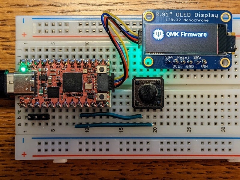
Adafruit Learning System
Build & Install an Open Source keyboard firmware for RP2040 microcontrollers
 whole saffron
How would people recommend using an Arduino with a bunch of inputs to be used as a controller for a game?
north stream
Have it send a representation of the inputs along to the machine hosting the game?
whole saffron
I kinda want it to have custom keyboard inputs if possible
upper robin
whole saffron
How would people recommend using an Arduino with a bunch of inputs to be used as...
What did ya have in mind, like a macro-based keyboard for wasd games or an enhancement for a gamepad controller? PC, Console or homebrew?
whole saffron
upper robin
What did ya have in mind, like a macro-based keyboard for wasd games or an enhan...
PC, specifically DCS :3
solemn cliff
and by "an arduino" do you have one you want to use (which one?) or can you be convinced to use one that has native usb and can act as a HID keyboard or controller ? (Like an arduino micro or a raspi pico)
whole saffron
Its an Uno
upper robin
solemn cliff
and by "an arduino" do you have one you want to use (which one?) or can you be c...
It would be a lot easier with a microcontroller that supports HID.
solemn cliff
ah that doesn't have USB OTG, that's gonna be complicated
in fact considering the low price of the pico and other similar boards, I would consider a much better choice to buy one of those than deal with the complexity of trying to do it with a Uno
upper robin
whole saffron
Its an Uno
I agree with @solemn cliff I just picked up a pi pico W at micro center for $5.
solemn cliff
(and use QMK or look at one of the many CP macropad guides on the adafruit website)
upper robin
And the pico has a HID/keyboard library available
whole saffron
solemn cliff
in fact considering the low price of the pico and other similar boards, I would ...
Sounds good. I was actually gonna buy some from a store in town tomorrow
livid osprey
An original uno can be modified to add usb hid, but it’s a fairly complex process that involves reflashing the 32u4 that’s typically used as usb to serial. Better to use a pico or something.
Oh shoot that was from yesterday woops
 tardy iron
i think it's either an ATmega8u2 or ATmega16u2, depending on revision, and yeah, you have to be comfortable with using SPI for programming it
i guess you could put a USB CDC bootloader on it, but it might be quite cramped for application code after that
whole saffron
Question about the Pico, any advantages the Pico has over the Pico W?
upper robin
whole saffron
Question about the Pico, any advantages the Pico has over the Pico W?
The W has WiFi and costs a dollar or two more.
If the command set were kept on the smallish side the DigiSpark would be worth a look too.
balmy crow
good afternoon, I have an ancoded mp3 file and used progmem, however I want the sound to play when I use a button and cant figure out how to code it. I have it in pin 11 when it works but cant find in the code where it says its directed to pin 11 does anyone know?
north stream
balmy crow
good afternoon, I have an ancoded mp3 file and used progmem, however I want the ...
I'm not sure what you're asking here. My best guess is you have some software that plays an MP3 when it receives a signal on pin 11, but you can't find where the software specifies pin 11?
balmy crow
#include <PCM.h>
const unsigned char sample[] PROGMEM = { enter code for mp3 here };
void setup()
{
startPlayback(sample, sizeof(sample));
}
void loop()
{
}
I have this to play the sound and want it to activate with a button
thats what I'm trying and it only plays when in pin 11 I excluded the code for the sound bc its very long
north stream
Something like this? ```arduino
#define BUTTONPIN 11
void setup()
{
pinMode(BUTTONPIN, INPUT_PULLUP);
}
void loop()
{
if (!digitalRead(BUTTONPIN)) {
startPlayback(sample, sizeof(sample));
}
}
im gonna try a few things but it allready helped, I just started playing a zooming noise but its something haha
balmy crow
I might have something wired wrong? Because I tried a few things but the speaker just makes a weird sound and the button does nothing 😅🙏
 tardy iron
an Arduino Uno is probably going to have trouble driving a magnetic speaker directly (and flyback voltage may damage the chip’s GPIO circuitry)
the button looks like it’s wired to connect a 4.7k resistor between 5V and ground?
balmy crow
its connected to a resistor and that one to ground and the other pin of the button is connected to 5v but wasnt sure how to connect the grnd pin of the speaker, the way it is now it just makes sound but could have done it wrong
 heavy star
Connecting the button to ground and 5V is just gonna short your power
The speaker might be making a sound because of the sudden voltage change when you press the button?
balmy crow
it makes the sound regardless of pressing the button, even if I take the button out it makes the sound haha
tardy iron
that seems consistent with the code you posted previously. it doesn’t read the pin. also, no GPIO pin is wired to the button
heavy star
Ah. Well, the button won’t do anything like that
The button should be connected to a GPIO and either ground or 5V, but not both, and your code needs to read if the GPIO is pulled high by connecting to 5V or low by connecting to ground
tardy iron
for a simple on/off input, the resistor isn’t strictly necessary, but can help prevent damage to the chip if you have the wiring or code set up wrong
balmy crow
aah okay thank you, I looked at a few vids and they did it this way. im very new to it haha
heavy star
Some videos make it hard to tell what they’re actually doing, lol
And some do things that are unnecessary because they don’t know any better
tardy iron
still good to use one in case you accidentally set a GPIO to output or something. though i’d personally use something smaller like 1k
livid osprey
balmy crow
good afternoon, I have an ancoded mp3 file and used progmem, however I want the ...
Looks like the pin is defined in the PCM library. https://playground.arduino.cc/Code/PCMAudio/
It does say to use only pins 3 or 11, as the code seems to call out the specific peripheral tied to those pins.

 wheat condor
Hi, I need to connect to a feather ESP32s3 (the one with the TFT) using JTAG and OpenOCD, but neither the vanilla 0.12 nor the ESP32 fork want to connect to it. I noticed, that the USB IDs are different and tried the ones from my board, but no luck. Are there any resources that explain how to connect to the USB Serial JTAG? Anything I'm missing here?
north stream
If it's USB-serial, then it should appear as a serial port. If it doesn't appear as a serial port, you may need a different driver.
wheat condor
north stream
If it's USB-serial, then it should appear as a serial port. If it doesn't appea...
That's actually didn't help at all. If someone is interested, the reason seems to be, that the ESP32S3 is in a different mode due to the stock firmware, opening Arduino, choosing Hardware CDC and JTAG as USB Mode, setting the other options to CDC and JTAG-related settings and flashing a sketch will put that right. Now I can connect to it via OpenOCD, rather simple fix, had to install the Arduino IDE (1.8) though. Now both vanilla as well as the ESP32 fork detect the board
wheat condor
Can someone give me a reasonable power draw, the Feather S3 TFT can handle, my setup seems to keep resetting in certain situations I've yet to suss out, but it looks like the 3v3 rail collapses
 wraith current
@wheat condorunder what circumstances does it collapse ? At random or with a full brightness event or what ?
wheat condor
Well, I run a DRV2605, a VS1053, seesaw and an OrangeCrab off it, normally things are fine, but if I try to play sound on the VS1053, chances are high and if I have the DRV2605 play a longer rumble it tends to at minimum reset the seesaw
I'm running a very small ERM off the DRV2605
bit of a bigger setup, hence my question
north stream
It might make sense to run some of those off the VIN supply instead of loading down the 3.3V regulator powering the logic (and possibly putting spikes on it).
wheat condor
I'm using Stemma cabling for the DRV, the seesaw and VS1053 are run off the Feather rails, so I don't have any control over those and well, the OrangeCrab I could, it's a bit inconvenient though, since I then can't connect the 3v rail
 sage lichen
So I have a fairly large arduino project, and I am trying to figure out how to run it locally only with the libs that arduino has access to
So like without the std library
north stream
What, the Arduino core library?
tardy iron
do you mean you want to simulate an Arduino on your computer?
sage lichen
Pretty much I am able to make "sim" versions of the libraries we've made for interacting with sensors and encoders and stuff, but I'm just looking for a way for me to have a local test env for me to run everything
I dont need to interact with pins or read values from pins or anything
Since all that is abstracted away anyways and can be easily swapped out
Just looking for a way to be able to test my code to make sure i'm not going out of the arduino standard library
 zinc mortar
If you're just checking your calls, then compiling & linking should do the trick, no?
wheat condor
sage lichen
Just looking for a way to be able to test my code to make sure i'm not going out...
Why? STL is a very good set of tools, even on embedded and it compiles down to almost nothing in most cases. It's just a matter of learning to use it and then quality of of the libs you use as well as your own code will be much better than what's currently floating around built purely on Arduino
sage lichen
Pretty much its a flight controller for an airbake on a HPR and we have past sensor data that we are able to run through it, but we just want to make sure the algorithms are working correctly now and make further changes without having to recompile onto the board. Also can allow for actual TDD and stuff like that. One of the issues that prompted this was someone wrote a bunch of code that used stuff in the standard library but not available within arduino without doing some craziness
So just want to be able to test (not just compile, but execute) all that code without having to put it onto an actual microcontroller
Just speeds up the development process a ton
Really I'm just trying to figure out what solution they use in the industry for testing. Found something for doing exactly this, but for the STM32 in Rust
tardy iron
i think there is at least one AVR simulator. i don't know how easy it is to use, though
sage lichen
Yeah I had found something but it required running a jypiter notebook and stuff
I just wanna force the compiler to only use the arduino standard library
Emulate arduino standard library functionality such as "millis()"
And map "Serial.out.println()" and stuff like that to use stdout
zinc mortar
So you want to basically mock that stuff like you would in a unit test?
sage lichen
If this doesn't exist I'll just make it myself ig
Yes
But an integration test
One step below HIL
zinc mortar
Sounds like you have a lot of work to do; there's a lot in that API 🙂
sage lichen
Yeah that was why I was hoping there was something already out there 😅
I would just implement the functions we're actually using but still thats effort that could actually go into getting it to work lol
wheat condor
sage lichen
Pretty much its a flight controller for an airbake on a HPR and we have past sen...
I would actually do the crazyness to get access to STL. I'd also try to use those types in favour of Arduino. Then you can actually test your code as you normally would, just refrain from bit-twiddling past the architecture size. Since the Arduino standard library isn't as big, you could also mock that, but really, just use proper C++ and STL
sage lichen
Thats true
tardy iron
mocking the (AVR) Arduino API on a computer won't catch the kinds of bugs you'll run into that are due to the AVR being 8 bits and your computer being 32 or 64 bits
sage lichen
Ok I guess I should have started with asking the actual question instead of jumping towards my (unoptimal) solution 🤣
The actual problem we ran into was people used vectors in a bunch of code
For matricies and stuff
And I didn't want to rewrite that stuff to not use vectors if I didn't have to since its way way above my head (I haven't taken linear algebra or anything)
tardy iron
compiling without uploading would have caught stuff like that, right?
sage lichen
Yeah it would've they were really dumb for even doing that
But at the same time, theres no intellisense in the old arduino ide
And the new ide is complete trash
So everyone just uses vscode (or clion)
tardy iron
there is a VS Code plugin for Arduino. it's a bit buggy and maybe not very well maintained
sage lichen
Yeah
wheat condor
That's your next mistake then, Arduino and its IDE is meant for small projects, use a real IDE, no VS Code, no Sublime, use Qt Creator or Visual Studio, mod your boards to upload via JTAG instead of the weird Serial and use proper debuggers
sage lichen
Oh trust me I am
Step by step tho
I'm working on a stm32 based board running rust with a jtag connector that can be emulated locally and have full test coverage and everything
But for this specifically we just have to work with what we have
tardy iron
proper on-chip/in-circuit debugging is amazing once you get it to work. my experience is you have to fight a lot to get the debug tools to work in any particular setup
sage lichen
Yeah I can imagine
wheat condor
Just got my first ESP32, was a bit of a pain to get USB JTAG running, but not too bad
sage lichen
But yea I try to use CLion for my contributions to everything, I'm just trying to figure out how to get it set up to work correctly (ie: recognize imported libs, etc)
Would something like this work? https://github.com/maniacbug/StandardCplusplus/blob/master/README.md

GitHub
Standard C++ for Arduino (port of uClibc++). Contribute to maniacbug/StandardCplusplus development by creating an account on GitHub.
wheat condor
Anyways, using std::vector for matrix math is a bad decision on that coders part, there are better types, since the size is static, but you should be able to convert that to straight up arrays easily. You can even try to rename std::vector to std::array and see what breaks. I'm not sure if uClib++ is even necessary to be honest, I'd just use the STL to get started and see what needs optimization later
sage lichen
Thats true
Yeah I guess I should just put in the work instead of finding a workaround
No reason for dynamic memory allocation for fixed sized matricies
wheat condor
Best way to not have to deal with stuff like that btw.: Talk to the coder, build guidelines and add linting and tests, that prevent this in the first place
sage lichen
Yea the problem was they kind of flaked on us
All of this was supposed to be done by them and ready by our launch yesterday
It wasn't 😦
And they didn't let us know until like 2 days prior
But yeah I def wanted to add tests which was one of the reasons for my initial question haha
wheat condor
also a typical occurance with at least 1/3rd of professional devs
sage lichen
But yea it should be pretty simple to write a header library to create bindings for some for the arduino standard library stuff like millis and serial.out
sage lichen
wheat condor
also a typical occurance with at least 1/3rd of professional devs
Oh yeah I've been there too
wheat condor
Anyways, good luck
 valid hazel
@sage lichen Have you looked at wokwi? https://wokwi.com/ You can add whatever libraries you want and it seems to be a very good emulator.

Arduino Simulator: Uno, Mega, ESP32, FastLED, LCD1602, Servo, Raspberry Pi Pico, Sensors. Designed for makers, by makers.
sage lichen
valid hazel
<@1010519081230811186> Have you looked at wokwi? https://wokwi.com/ You can add ...
Interesting, thanks for the send
Was hoping for something I could run on my own machine so I could do tests and stuff but beggars cant be choosers haha
tardy iron
the one i've heard of is called avrsim or something like that. i don't know how easy it is to work with
sage lichen
Omg I'm very stupid
So remember that emulator I was talking about earlier
The one that works with rust
Well uh
It works with the machine code generated after compiling rust (duh)
Which means it works just fine with arduino stuff 💀
If anyone wants to know the name its called QEMU
Sorry about that, had a huge brain fart lol
tardy iron
whoa, i didn't know qemu did AVR
upper robin
sage lichen
If anyone wants to know the name its called QEMU
Thanks for sharing ..... I'm going to look into it.
 cinder sonnet
Hey ya'll - I wanna get an arduino or raspberry pi on my network so I can WOL my PC and NAS remotely. I haven't ever an arduino ro raspberry pi. Any recommendations on what to get if WoL was it's only purpose?
wheat condor
cinder sonnet
Hey ya'll - I wanna get an arduino or raspberry pi on my network so I can WOL my...
Have you checked, if you can flash your router firmware? Might already be the additional device you need. Otherwise, the smaller and lower power you go, the more complicated. You may even be able to do it with an Atmega328 with ethernet powered via USB, but it's a "project". I'd look for the smallest device with an ethernet port and linux capabilities, a Raspberry Pi is a pretty safe and reasonably easy bet.
cinder sonnet
wheat condor
Have you checked, if you can flash your router firmware? Might already be the ad...
That's really helpful. Thanks Paul. Unfortunately I have to go this route because I'm on an ISP provided router so flashing not an option (I assume not anyway). Plus, I'll be using Tailscale with this pi/arduino device so I don't have to poke holes in my firewall on the router. I'm going to be looking at some cheapo Raspberry Pi's per your rec. Thank you!
wheat condor
cinder sonnet
That's really helpful. Thanks Paul. Unfortunately I have to go this route becaus...
BreadBee might be interesting, 5V/138mA according to the GitHub page. Haven't tried it though
cinder sonnet
wheat condor
BreadBee might be interesting, 5V/138mA according to the GitHub page. Haven't tr...
That does look interesting. I just picked up a Raspberry Pi so I'll start there. I just picked up an older Raspberry Pi w/ ethernet. If that fails, I'll let you know if I give that BreadBee a shot!
🙏
wheat condor
Hmm, yeah, a 1st gen Pi might be a really good choice as well
 quaint nebula
Arduino cannot seem to detect the adafruit itsy bitsy
north stream
Which ItsyBitsy? The 32U4 should show up as a serial device, but most of the others may default to mass storage devices at first.

 north stream
That looks like a driver issue, but I didn't think the 32U4 needed a driver. Weird.
The learn guide does have a link for drivers if you're running windows https://learn.adafruit.com/introducting-itsy-bitsy-32u4/using-with-arduino-ide
quaint nebula
I’m updating windows rn
 north stream
Does it show up as a USB device? Are you sure you have a good cable (that's a data cable, not a charging cable)?
quaint nebula
Lemme check
 inland gorge
quaint nebula
inland gorge
quaint nebula
I believe 32u4 devices will only show up as a USB device if they’re in bootloader mode (double click reset) or have already had an Arduino sketch uploaded to them
 urban crater
Hi all! I have bought a Trinket 3.3v. Currently I have downloaded Arduino IDE and installed the boards thru board manager but still have no connection to my trinket. I can see it in device manager but not thru Arduino. Any advice to get my trinket connected?

 north stream
The old ATtiny based Trinkets don't work well with modern USB chipsets. You may need to set the programmer type to "USBtiny" or somesuch in Arduino, and sometimes an old USB hub can act as a data converter.
 elder hare
could you run discord.py lib on an ESP32 running micropython? 🤔
 sage fern
anyone here have issues with the max6675 thermocouple reader?
frequently it reports that the thermocouple has disconnected, and a hard reset is required
 half pollen
Can I use the Elegoo Uno R3 with the PN532 shield or would the M7 be a better option. New to hardware coding but I think I should use Circuitpython with Mu and I2C.
north stream
The shield should work with either, but CircuitPython won't run on the Uno.
 safe summit
have a nice day. I try bno055 with stm32 and i have issue about connection i think. pls chechk this link https://electronics.stackexchange.com/questions/658286/adafruit-bno055-sensor

Electrical Engineering Stack Exchange
Have a nice day.
My sensor is https://learn.adafruit.com/adafruit-bno055-absolute-orientation-sensor/overview
I tried to run it using different libraries but it never worked.
I want to see sersor r...
north stream
safe summit
have a nice day. I try bno055 with stm32 and i have issue about connection i th...
Have you tried the suggestions people made there? Did you do an I2C scan to see if anything answers up?
safe summit
actually sir , i tried answer one
first write chip_ıd then try get data
HAL_I2C_Mem_Write(&hi2c3, (0x28 << 1), BNO055_CHIP_ID, 1, &Data, 1, 1000);
still not work
north stream
Try doing an I2C scan
half pollen
Would this be the place to get help for the Metro M7?
safe summit
north stream
Try doing an I2C scan
i tried and not working hmmm
 rugged merlin
I have the esp32 s3 2mb psramm, and the arduino software succesfully sees the com port, however when i try to upload code it says "A fatal error occurred: Could not open COM4, the port doesn't exist"
rugged merlin
However, the board does work with circutpython, which is weird.
But I'd rather use arduino IDE if thats an option
Nevermind, I got iit working
north stream
safe summit
i tried and not working hmmm
If it doesn't show up on an I2C scan, that implies you have a hardware problem
safe summit
have a nice day .I performed an I2C scan on a different sensor mpu6050 using the same pins and it was successful. I don't think it's an issue with my mcu.
north stream
Ah, that does narrow it down. So it seems to be an issue with that particular peripheral.
safe summit
hmm what do u mean?
north stream
As you discovered, the MPU6050 shows up on an I2C scan, so it and its wiring, along with the CPU and it's I2C port, are working. However, the BNO055 doesn't show up on an I2C scan with (presumably) the same connection, implying the problem lies with the BNO055 or its wiring.
 whole ibex
Not sure if this is the right channel to ask at but
I am beginner and I just came across this

Is this table correct?
north stream
It's not really an Arduino question, but we'll go with it. The table does not look correct to me. The first column looks like NOT (A OR B) to me and the second column looks like NOT (A XOR B)
Um, I just saw the prime symbols, so that may be right
At least the first column
whole ibex
If A+B is 0+0=0 and then that (0)' = 1 isnt it?
whole ibex
I was trying to find a logisim evo discord since that is the program I am running the simulations at but there doesnt seem to be one
north stream
I don't know of one, but I only hang out on a few Discords
whole ibex
Well, what has confused me is that in the simulation for the first function, 0,0 inputs give 0 output
When I was expecting 1
livid osprey
whole ibex
Well, what has confused me is that in the simulation for the first function, 0,0...
What are you using for simulation?
whole ibex
It works now, It was a problem with the switches
 glossy grove
Hi! I'm having trouble understanding the General Timers, particularly the GTCCR. I did try to read through the datasheet but that has not helped simplify things for me. There are 3 marked bits in it( 0, 1 & 7) however I don't quite understand what the other ones are doing.
 cedar mountain
glossy grove
Hi! I'm having trouble understanding the General Timers, particularly the GTCCR....
cedar mountain
glossy grove
Hi! I'm having trouble understanding the General Timers, particularly the GTCCR....
The other bits are unused. The diagram just says they will always read as 0 and can't be written to.
glossy grove
thamks!
glossy grove
I have another question, when disabling PWM output, do we have a choice to clear the OCR registers or the timers? Will either one work? For context, I'm trying to write my own digital read & write functions
 earnest stratus
I have a question about the ESP32-S3 TFT Feather. There's an LED that lights up when the device is charging. Is there a way to read the status of that light, or power source, from arduino code?
solemn cliff
the only thing connected to the battery pin is the LC709203F battery monitor, I don't know what it says when it's charging or if it can be used to know that it is
earnest stratus
Thanks.Yeah, if it's in the LC709203F library, it isn't clear where.
 dry quiver
I ran into a similar question but with the Qt Py lipo charger bff, which uses the same charger as the TFT feather apparently. That chip (MCP73831) has a stat pin, which powers the LED before going to VBUS.
What the bff does that is different from the feather though is that there's a voltage divider from VBUS that is hooked up to an analog pin so you can reference the battery voltage from there.
You can probably emulate that by doing the same externally.
 rugged mirage
does anyone know what exactly the arduino IDE does to open a serial port, i'm trying to write C++ code to mimic the serial monitor behavior and i can send data just fine but reading it is weird, m code works to read if I've already opened u the port, so to say, with the serial monitor in the arduino IDE, but my code wont read anything, it can still write, from the arduino if i unplug it and run my code without first "initializing?" the serial port in the arduino IDE with the serial monitor
tardy iron
serial port stuff is often very OS-dependent. also, if you have multiple processes opening the same serial port for reading, it can be unpredictable which of them gets the output at any particular time
rugged mirage
im using this hacky serial/serial library for C++ i found in some tutorial maybe i should just learn how to do it in windows. the hope was this library was cross platform and more portable and also easier to wrap my head around but i think it just doesn't wokr well
 glossy cradle
Going out on a limb but anyone have some reference material for writing code to communicate with a LTC1864 with either Pico, Arduino, or STM32. It uses 3 wire SPI instead of the usual 4 wire, referred to as MICROWIRE™
livid osprey
glossy cradle
Going out on a limb but anyone have some reference material for writing code to ...
It's a weird SPI chip, using only MISO and SCK for the SPI bus, and a single GPIO for conversion. A standard SPI bus peripheral should read data just fine with CONV as CS, but the conversion timing might be weird if you're not reading the ADC at short intervals.
 glossy cradle
It is indeed a weird SPI chip, I will try using the standard SPI library as you suggest
Just have a feeling I'm in for some pain with the conversion timing
glossy grove
can someone help me debug a part of the code, I absolutely don't understand whats happening and I don't know if I should copy paste the whole thing since it annoys some people. I'm just starting with the error: if someone can help me understand what it means;
avr-gcc -o .pio/build/circuitplay_classic/FrameworkArduino/wiring_digital.c.o -c -std=gnu11 -fno-fat-lto-objects -mmcu=atmega32u4 -Os -Wall -ffunction-sections -fdata-sections -flto -DPLATFORMIO=60106 -DARDUINO_AVR_CIRCUIT_PLAYGROUND_CLASSIC -DF_CPU=8000000L -DARDUINO_ARCH_AVR -DARDUINO=10808 -DUSB_VID=0x239A -DUSB_PID=0x8011 -DUSB_PRODUCT="Adafruit" -DUSB_MANUFACTURER="Adafruit" -I/home/aira/.platformio/packages/framework-arduino-avr/cores/arduino -I/home/aira/.platformio/packages/framework-arduino-avr/variants/circuitplay32u4 /home/aira/.platformio/packages/framework-arduino-avr/cores/arduino/wiring_digital.c
In file included from /home/aira/.platformio/packages/framework-arduino-avr/cores/arduino/Arduino.h:258:0,
from /home/aira/.platformio/packages/framework-arduino-avr/cores/arduino/wiring_private.h:31,
from /home/aira/.platformio/packages/framework-arduino-avr/cores/arduino/wiring_digital.c:26:
/home/aira/.platformio/packages/framework-arduino-avr/variants/circuitplay32u4/pins_arduino.h:292:1: error: expected '=', ',', ';', 'asm' or 'attribute' before 'const'
const uint8_t PROGMEM analog_pin_to_channel_PGM[] = {
^~~~~
*** [.pio/build/circuitplay_classic/FrameworkArduino/wiring_digital.c.o] Error 1
===================== [FAILED] Took 0.26 seconds =====================
 hexed sphinx
Arduino Forum
Hi, I'm using the autowp-mcp2515 and Arduino_PortentaBreakout library for a CAN BUS interface using the Arduino Portenta H7 Lite. #include #include #include struct can_frame canMsg; MCP2515 mcp2515(SPI1_CS); void setup() { Serial.begin(115200); mcp2515.reset(); mcp2515.setBitrate(CAN_125KBPS); mcp2515.setNormalMode(); Ser...
 dusk orchid
Hello helpful people, I'm getting a redefinition error, I'm including lvgl_glue which includes another library that defines one class. I then need to include another touchdriver and it also declares that class. How can I stop the conflict, or undefine the first one, or specify the FT version rather than STMPE version?

 thorny cedar
Hello! Anyone know how to configure pin 13 on the feather m0 adalogger board to work as a TX pin in a serial communication, without interfering with the red LED? Any tips would be appreciated!
My code:
#include <Arduino.h>
#include "wiring_private.h"

#define BAUD_RATE (9600)
#define SERIAL_CONFIG (SERIAL_8N1)

/*
Pin    Arduino 'Pin'    SERCOM        SERCOM alt
-----------------------------------------
PA18    D10        SERCOM1.2    SERCOM3.2
PA16    D11        SERCOM1.0    SERCOM3.0
PA19    D12        SERCOM1.3    SERCOM3.3
PA17    D13        SERCOM1.1    SERCOM3.1

Source: https://learn.adafruit.com/using-atsamd21-sercom-to-add-more-spi-i2c-serial-ports/creating-a-new-serial
*/
const uint8_t RX_PIN = 11;
const uint8_t TX_PIN = 13;
//Uart mySerial(&sercom1, RX_PIN, TX_PIN, SERCOM_RX_PAD_0, UART_TX_PAD_2);
Uart mySerial(&sercom3, RX_PIN, TX_PIN, SERCOM_RX_PAD_0, UART_TX_PAD_2);

void setup()
{
  // I guess the problem is here
  // pinMode(13, INPUT_PULLUP);
  digitalWrite(13, LOW);

  mySerial.begin(BAUD_RATE, SERIAL_CONFIG);

  pinPeripheral(11, PIO_SERCOM_ALT); // Assign RX function to pin 11

  pinPeripheral(13, PIO_SERCOM_ALT); // Assign TX function to pin 13
}

/*
void SERCOM1_Handler()
{
  mySerial.IrqHandler();
}
*/

void SERCOM3_Handler()
{
  mySerial.IrqHandler();
}

void loop()
{
  // This works (RX)
  if (mySerial.available() > 0)
  {
    Serial.println(mySerial.readString());
  }
  delay(1000);
  // This is not working (TX)
  mySerial.println("foo");
  Serial.println("foo");
  delay(1000);
}
 gilded swift
thorny cedar
Hello! Anyone know how to configure pin 13 on the feather m0 adalogger board to ...
gilded swift
thorny cedar
Hello! Anyone know how to configure pin 13 on the feather m0 adalogger board to ...
It’s not really possible, D13 is directly connected to the LED. You could remove it’s resistor if you don’t want it turning on.
thorny cedar
gilded swift
It’s not really possible, D13 is directly connected to the LED. You could remove...
Thanks!
 craggy wren
Quick question: I'm currently using some Arduino Nanos and the RadioHead library ReliableDatagram manager with Adafruit RFM69HCW modules. I'd like to replace that hardware with Arduino Megas and RFM96W LoRa modules and use RHMesh instead of ReliableDatagram. My expectation is that I'll include and use a different driver and manager from the library and otherwise everything will work just the same - right?
The Mega shouldn't have any memory issues in particular?
 icy nimbus
glossy grove
can someone help me debug a part of the code, I absolutely don't understand what...
icy nimbus
glossy grove
can someone help me debug a part of the code, I absolutely don't understand what...
This looks more of a platform io issue, check over with them.
 leaden pike
hey, does anyone know how to fix a problem I'm having with the 4x4 adafruit trellis and button cover? when we run the test code on one of the PCBs, 5 buttons aren't taking input (not lighting up when pressed, and not displaying as pressed in the arduino serial moniter), even though they light up when the code starts.
thorny cedar
Hi! Does anyone know how I can perform differential analog readings using the built-in ADC of Feather M0 Adalogger?
 inner crest
Hello all, I recently got a adafruit feather 32u4 and a featherwing power relay and because they are so new, there are not many tutorials on how to code them, I want the code the feather 32u4 to turn on and off the relay, how would I do that in the Arduino IDE?
livid osprey
inner crest
Hello all, I recently got a adafruit feather 32u4 and a featherwing power relay ...
The Relay Featherwings are controlled by a single GPIO of your choice. Just close one of the solder jumpers on the bottom of the board to connect it to the pin you want, and digitalWrite(pin, HIGH) turns the relay on.
 inner crest
livid osprey
The Relay Featherwings are controlled by a single GPIO of your choice. Just clos...
inner crest
livid osprey
The Relay Featherwings are controlled by a single GPIO of your choice. Just clos...
alright I soldered the bottom part then put it on the feather 32u4 but how do I code the relay to turn on and off at any time I want?
// digitalWrite(pin, HIGH) turns the relay on.
// digitalWrite(pin, LOW) turns the relay off. (will see below, pin = motor)


// the setup function runs once when you press reset or power the board
void setup() {
  // initialize digital pin motor(1) as an output.
  pinMode(motor, OUTPUT);
}

// the loop function runs over and over again forever
void loop() {
  digitalWrite(motor, HIGH);   // turn the motor on (HIGH is the voltage level)
  delay(5000);                       // wait for 5 seconds(while on high)
  digitalWrite(motor, LOW);    // turn the motor off by making the voltage LOW
  delay(2000);                       // wait for 2 seconds (while on off)
}'''` and ' are different haha
inner crest
yup... lol
livid osprey
Code looks right. Did you solder pin 9?
inner crest
ya
inner crest
I need to switch the wires from the uno to the bluefruit but haven’t managed yet
No errors
livid osprey
No click in the relay at all?
livid osprey
inner crest
Your wires might be too long? If the resistance of the wires is too high, your coil might not be able to draw enough current to actuate the relay?
inner crest
oh no, sorry, it works just the CIM motor doesnt fully turn and I don't know how to code it to rotate more/in different positions and is there a way to set a button to turn the relay on/off?
north stream
It's easy enough to have the relay on while the button is pushed, but I'm guessing you want it to toggle?
livid osprey
inner crest
oh no, sorry, it works just the CIM motor doesnt fully turn and I don't know how...
I can’t tell exactly what kind of motor you have, but I do see a motor controller that could possibly be stopping your motion?
inner crest
I have a Spark motor controller, a 12V Cim motor, 2x 9V batteries in series connection to make 18V, the Uno, and the feathers
I tried the two seperate circuits and they worked. (the spark controller, the cim motor and the battery) and (the relay and bluefruit 32u4, and the battery and a small dc motor) but just trying to get them together
inner crest
north stream
It's easy enough to have the relay on while the button is pushed, but I'm guessi...
Ya, eventually I want to code an ios app to basicly turn the relay on/off with a button on the app and that turns the tech on/off
north stream
You could make the app take care of it but with a physical switch, you'd read it in a loop, keep track of the previous state, and toggle when the state has changed from "not pressed " to "pressed "
 loud horizon
Can anyone help me on this?
"Hello, I'm confused about this apparent avrdude error that keeps coming up when connected. It's recognized as a ch340 device with updated drivers for the 340, but nowhere on the chip does it say it's a 340. Can anyone help?"
 inner crest
north stream
You could make the app take care of it but with a physical switch, you'd read it...
inner crest
north stream
You could make the app take care of it but with a physical switch, you'd read it...
Alright but then how would I code the CIM to move more smoothly along with the relay toggle? This is what I currently have:
// digitalWrite(pin, HIGH) turns the relay on.
// digitalWrite(pin, LOW) turns the relay off. (will see below, pin = motor)


// the setup function runs once when you press reset or power the board
void setup() {
  // initialize digital pin motor(1) as an output.
  pinMode(motor, OUTPUT);
}

// the loop function runs over and over again forever
void loop() {
  digitalWrite(motor, HIGH);         // turn the motor on (HIGH is the voltage level)
  delay(5000);                       // wait for 5 seconds(while on high)
  digitalWrite(motor, LOW);          // turn the motor off by making the voltage LOW
  delay(2000);                       // wait for 2 seconds (while on off)
}
Looks like a protocol issue, not a driver issue: try changing the programmer type
loud horizon
Any help for me?
inner crest
loud horizon
Any help for me?
that is for you mate...
inner crest
north stream
Looks like a protocol issue, not a driver issue: try changing the programmer typ...
@loud horizon
loud horizon
sorry i assumed you were responding to that other guy
 hazy moon
I'm looking for a working example of Arduino code that wakes a MagTag from ESP32 deep sleep with a press on any of the onboard buttons. Per https://learn.adafruit.com/adafruit-magtag/pinouts, there are no pullups for these pins and go LOW when pressed. I've used the ESP32 ExternalWakeUp example (it appears in almost every online tutorial with minor modifications) with odd results. Using esp_sleep_enable_ext0_wakeup, I can wake from sleep on GPIO14 properly, but not GPIO15 or GPIO12 . Reviewing the MagTag pinout diagram, it's not clear what difference between GPIO14 and GPIO12 would be to cause this. Using esp_sleep_enable_ext1_wakeup doesn't work at all, regardless of what pins I set in the bitmask. ext1 has the disadvantage of its second parameter being any pin in the bitmask HIGH or all pins in the bitmask LOW. I added an rtc_gpio_pulldown_en() for one pin and modified the bitmask to use only that pin, but that didn't work either. I'm stumped and hope someone in the community figured this out. I've also got a Adafruit Feather ESP32S2 with the 2.9" epd Featherwing attached (three buttons, D11,12,13) that has the same problem with ext1. I haven't tested ext0 with it, as I really need the solution to respond to any of the buttons, not one specific button.
 digital sonnet
Does anyone know if the TinyVideoLoops library is still available?
 shy oasis
hazy moon
I'm looking for a working example of Arduino code that wakes a MagTag from ESP32...
shy oasis
hazy moon
I'm looking for a working example of Arduino code that wakes a MagTag from ESP32...
There is a note on page 93 in https://cdn-learn.adafruit.com/downloads/pdf/adafruit-magtag.pdf that says that the ESP32-S2 is limited to one or two pins when pulled low for wakup.
digital sonnet
digital sonnet
Does anyone know if the TinyVideoLoops library is still available?
Does this even exist?
digital sonnet
Im trying to figure out how to play back a video file with a TFT display pulling from an SD card over SPI
 sick thicket
Hey there! I'm trying to make a keyboard but I'm encountering an issue where the hardware isn't detecting or appears to be running any code when I do the following setup:
#include <Adafruit_TinyUSB.h>
#include <Adafruit_NeoPixel.h>

uint8_t const desc_hid_report[] = { TUD_HID_REPORT_DESC_KEYBOARD()};

Adafruit_USBD_HID usbhid (desc_hid_report, sizeof(desc_hid_report), HID_ITF_PROTOCOL_KEYBOARD, 2, false);

bool activeState = false;

void setup(){
  #if defined(ARDUINO_ARCH_MBED) && defined(ARDUINO_ARCH_RP2040)
    TinyUSB_Device_Init(0);
    #endif

  usbhid.begin();
  pinMode(LED_BUILTIN, OUTPUT);
  digitalWrite(LED_BUILTIN, LOW);

  while(!TinyUSBDevice.mounted()){delay(1);}
}

void loop(){
  delay(10);
  Serial.println("Hello!");
}
I'm not sure what's wrong with this code, my raspberry pi pico w isn't being detected when I run it. Thank you for your help!
 languid quartz
I've got an MPL3115A2 and an Arduino Nano RP2040 Connect using CircuitPython and I'm trying to just read from it but it doesn't work. It gives me the error
Failed to find MPL3115A2, check your wiring!
Here's the code I'm using.
import time
import board
import adafruit_mpl3115a2

i2c = board.I2C()
sensor = adafruit_mpl3115a2.MPL3115A2(i2c)
sensor.sealevel_pressure = 1022.5

print('Pressure: {0:0.3f} pascals'.format(sensor.pressure))
print('Altitude: {0:0.3f} meters'.format(sensor.altitude))
print('Temperature: {0:0.3f} degrees Celsius'.format(sensor.temperature))
It works with my other arduino uno but not my RP2040
cedar mountain
languid quartz
I've got an MPL3115A2 and an Arduino Nano RP2040 Connect using CircuitPython and...
Well, I mean the obvious question is, what is your wiring like?
languid quartz
cedar mountain
Well, I mean the obvious question is, what is your wiring like?
3v to vin
Ground to Ground
SCL to A5 (SCL)
SDA to A4 (SDA)
I can send a picture if you want
cedar mountain
Cool, that sounds correct. Is it using a breadboard or soldered connections? (Read: are the connections solid or maybe somewhat loose?)
languid quartz
cedar mountain
Cool, that sounds correct. Is it using a breadboard or soldered connections? (Re...
Breadboard, all the connections seem to be solid.
cedar mountain
Do you happen to have a multimeter to check some voltages? The SCL and SDA pins should idle high at 3.0-3.3V, and the "3vo" pin on the breadboard should also be at 3.0V if it's getting power on Vin.
languid quartz
cedar mountain
Do you happen to have a multimeter to check some voltages? The SCL and SDA pins ...
SCL and SDA are giving 3.0-3.3 volts and so is the 3v pin.
cedar mountain
Cool, are you reading the same when probing on the Nano side of the SCL and SDA connections?
languid quartz
cedar mountain
Cool, are you reading the same when probing on the Nano side of the SCL and SDA ...
They're both reading 3 volts on the nano
cedar mountain
Cool. This is all looking good so far. Have you triple-checked that you're actually on A4 and A5 in the right order? It looks like the top side of the board doesn't have labels on it.
languid quartz
cedar mountain
Cool. This is all looking good so far. Have you triple-checked that you're actua...
yeah, they're at the right spot.
cedar mountain
Hmmm, this is getting to the "well, it should just work, then" stage, heh heh. The next step would probably be trying an I2C scanner sketch to see if anything is detected on the bus at all.
languid quartz
I ran the code at https://learn.adafruit.com/scanning-i2c-addresses/circuitpython and it gave me this I2C addresses found: ['0x60', '0x6a']

Adafruit Learning System
Hello? Are you there? Scan and find out.
cedar mountain
Great! The 0x60 is the standard address of the sensor, so it's being seen. I'm not sure what the 0x6A one is, but probably some other chip on the Nano board.
Hmmm, although I am seeing some references to the Nano detecting those addresses by itself, too. You might try disconnecting the MPL and scanning again... it's possible there may be an address conflict with something already built in to the Nano board.
languid quartz
cedar mountain
Hmmm, although I am seeing some references to the Nano detecting those addresses...
It's still retuning I2C addresses found: ['0x60', '0x6a']
cedar mountain
The 0x6A seems to be the IMU on the board.
languid quartz
cedar mountain
The 0x6A seems to be the IMU on the board.
Yeah, that's what I found. I decided to search MPL3115A2 in this discord, and there's a lot of references to it working weirdly with the RP2040. I found that the sensor uses SPI I2C. I'm not sure if that changes anything.
cedar mountain
I can't find what the WiFi radio's address is, but it has an I2C connection in the schematic too, so I suspect it's the 0x60 address conflict. 😢
So, unfortunately you're probably going to need to wire up the pressure sensor to a second I2C bus instead.
I'm not quite sure how CircuitPython handles this sort of thing, though.
 tacit jewel
what ethernet hat is compatible with arduino zero
north stream
sick thicket
Hey there! I'm trying to make a keyboard but I'm encountering an issue where the...
Does it enumerate at all?
dusk orchid
I'm crossing fingers that anyone can help...
I'm using the adafruit lvgl glue library, and it conflicts with one of the adafruit touch IC libraries (FT6206), because both STMPE610 included by lvgl glue and the ft6206 include the TP_Point class. The other thing is the Lvgl glue Begin() overloads require the STMPE610 which maybe could be rethought rather than adding the FT6206 overload and others too. I've gone down the route of using the Begin overload without touch, then I'll manually add touch.
So firstly thanks to the maintainers for latest fixes over the last few months, they've meant I can get lvgl going on the esp32s3 on wokwi (online or vscode arduino+esp32+pico simulator).
https://wokwi.com/projects/359264266487565313
How am I best proceeding if I don't want to include STMP610 which is brought in by lvgl-glue, should I create my own header file of matching name and include that first (with a define guard and recreate the class but without the TP_Point structure/class)

Run IoT and embedded projects in your browser: ESP32, Arduino, Pi Pico, and more. No installation required!
sick thicket
north stream
Does it enumerate at all?
I’m not sure what you mean, but I’m getting 0 output. The LED doesn’t turn on or off (this might just be because I’m using pico w and not the regular pico) and it’s not printing anything in the serial monitor. It doesn’t show up on device manager under USB, keyboard or COM ports. For the record other code ran just fine
north stream
sick thicket
I’m not sure what you mean, but I’m getting 0 output. The LED doesn’t turn on or...
Enumeration is the first step of connecting a USB device. If that succeeds, then a driver can attach to it, then software can work with it. If something doesn't work, I try to figure out where in the process if failed, which gives information on how to fix it
sick thicket
north stream
Enumeration is the first step of connecting a USB device. If that succeeds, then...
Right, that sounds great. But the thing is I have no clue how any of this works... I know that when a device would like to a communicate to a host it brings either D+/D- high based on what speed it would like to communicate. Then the host sends some data packages to ask for descriptors and configuration and then communication effectively happens. I don't know how to check any of this. I know this in theory from some youtube videos but I've never actually done any of this. I've tried using C/C++ and the pico-sdk to make my keyboard, but there is something wrong with the descriptors, I spent so much time trying to understand what is wrong but I don't have the tools to figure out what's going on. So I thought that using arduino + adafruit_tinyUSB would be a simpler option and I just followed the example, but it's either missing something or I am. Here is the example I was effectively copying: https://github.com/adafruit/Adafruit_TinyUSB_Arduino/blob/master/examples/HID/hid_boot_keyboard/hid_boot_keyboard.ino
and other than the fact that I'm not using neo-pixel I don't think there is much of a difference in the setup

GitHub
Arduino library for TinyUSB. Contribute to adafruit/Adafruit_TinyUSB_Arduino development by creating an account on GitHub.
hazy moon
shy oasis
There is a note on page 93 in https://cdn-learn.adafruit.com/downloads/pdf/adafr...
Thanks! Very useful data
north stream
sick thicket
Right, that sounds great. But the thing is I have no clue how any of this works....
Normally your computer will log things like USB attach events somewhere and you can examine the log to see what devices enumerate, and often which ones have drivers attached. Some systems offer tools to view this information as well.
sick thicket
north stream
Normally your computer will log things like USB attach events somewhere and you ...
I'll look into it thank you so much!
 random zealot

Blessed be. “Bring the whole tithe into the storehouse, that there may be food in My house. ‘Test Me in this,’ says the Lord Almighty, ‘and see if I will not throw open the floodgates of Heaven and pour out so much blessing that there will not be room enough to store it’” –Mal. 3:10.
OKAY BESIDES THIS INTRO
- FREQUENCY ARDUINO CODE
- ELECTRICAL OUTPUT W/FREQUENCY, WAVE ARDUINO CODE
- AUDIO OUTPUT W/FREQUENCY, WAVE ARDUINO CODE
....
Do you think you could help me find SNIPPETS of those codes? Blessed be ADAFRUIT
north stream
The general approach is generally to set up something like a timer interrupt that clocks out your samples at the desired rate.
random zealot
okay, sounds great! I wrote it in caps after a prayer because i found a lot of help in greek church
north stream
I have some code does that sort of thing but it was written before the handy libraries were available
 glacial viper
Hello, everyone, I have a question about displaying images on a Adafruit 2.9" E-Ink Display - Displaying 1-bit image
I am able to display a black & white image to the display using the display.drawBitmap() function. The successful image draw uses const unsigned char data stored in PROGMEM (see below):
const unsigned char epd_bitmap_small_logo [] PROGMEM = {0x00, 0x00, 0x06....ect};
However, I want to display image data sent over from a Python program that I wrote, that program converts an image into black & white pixels & stores the data in a byte array.
Then the byte array is sent over Serial to an Arduino MEGA 2560 in hex format so I can use it to write the image to the display. I have also verified the hex data that is being sent over is correct. But the no matter what I try the image is garbled.
Has anyone successfully displayed an image to one of these displays using data that came from Serial & is not stored in PROGMEM?
cedar mountain
glacial viper
Hello, everyone, I have a question about displaying images on a Adafruit 2.9" E-...
On the Arduino side, are you converting the data back from ASCII hexadecimal into the raw bytes? That is, 0x10 should be the byte 16, not two bytes of "1" and "0".
glacial viper
I think that is were I am going wrong & it seems like you know more about this than I do, despite reading everything I can find. I am almost certain I have two bytes of "1" and "0". I am stripping off the 0x from the ASCII hexadecimal, then I have a function that uses strtok to grab each hex value & store it into an unsigned char array which is then used with the drawBitmap function. An image is displayed, but its garbage.
char *sSample = "00 00 00 00 00 00 00 00 00 00 00 06..ect";
unsigned char Words[MAX_WORD_COUNT];
int word_count;
void setup() {
display.begin(THINKINK_TRICOLOR);
display.clearBuffer();
word_count = split_message(sSample);
display.drawBitmap(0,30,Words,62,60, COLOR1);
display.display();
}
byte split_message(char* str) {
int word_count = 0; //number of words
char * item = strtok (str, " "); //getting first word (uses space as delimeter)
while (item != NULL) {
   if (word_count >= MAX_WORD_COUNT) {
   break;
}
Words[word_count] = item;
item = strtok (NULL, " "); //getting subsequence word
word_count++;
}
return word_count;
}
Based on your suggestion, I think I got it partially figured out.
I needed to change Words[word_count] = item to:
Words[word_count] = 16*(item -'0')+((item+1)-'0');
rugged mirage
still having a really weird issue with some Cpp code I'm writing thats meant to mimic the arduino IDEs serial monitor/plotter. basically I've got arduino code that monitors some sensors on its analog inputs and sends the values over the COM port every cycle. my Cpp code can successfully detect and open the port, and send instructions to the arduino. and it can read the data from the arduino, in a very specific circumstance. my code right now can only read from the COM port if I first (best guess here) "initialize" the connection by opening the serial monitor inside the arduino IDE. if I unplug the arduino, plug it back in and run my code without opening the serial monitor in the IDE, I read absolutely nothing, i can still send to the arduino just fine, but no data can be read. my best guess is the arduino IDE does something whenever I open the serial monitor that tells the arduino to start sending characters into the COM port, but im not entirely sure what it's doing.
cedar mountain
rugged mirage
still having a really weird issue with some Cpp code I'm writing thats meant to ...
To clarify, is your code talking to the Arduino over a different serial port than the one used by the serial monitor?
rugged mirage
does the serial monitor use a different COM port than what I'm uploading to? using a pro micro, so I assume I only have the one COM port, I didn't wire up a secondary COM port.
my app can't read from the arduino WHILE the serial monitor is open. but it can if i open the serial monitor, close it, and then run my app
but not if i unplug, plug it back in, then run my app wihtout first opening the same COM port in the arduino IDE with the monitor
cedar mountain
Hmmm. Is there some sort of boot message printed by the Arduino, which your code is getting confused by but it works correctly if the serial monitor eats that initial data first?
rugged mirage
shouldn't be the case because I'm erasing everything in the buffer before I read
and i should at least be able to read the boot message
the only writing I'm doing in my code to the serial monitor is in one serial.println() call that writes the entire string containing all the sensor values
cedar mountain
The only other thing which comes to mind is maybe there's some sort of a delay, like the Arduino has to spend a little time between when the serial port is opened and when it's ready to receive a command, whereas your code is opening the port and sending something immediately.
rugged mirage
might be the case. i can replicate my success with another app called realterm
so maybe im making some kind of mistake while im opening the port
solemn cliff
does your code use flow control ? dts/cts ? I don't know if it's necessary, but I know that C# serial for example doesn't do it by default and it can cause issues in some cases
while terminal apps typically do it
rugged mirage
does ther arduino serial monitor use flow control?
i believe my app does not use flow control
yeah the default is no flow control and im not manually setting it to on in my constructor
yeah and when i open it with realterm im opening it with no flow control either
rugged mirage
cedar mountain
The only other thing which comes to mind is maybe there's some sort of a delay, ...
dont think this is it. setting a delay in my code after I open the port doesn't fix my issue
cedar mountain
Gotcha, yeah, I'm kind of grasping at possible straws at this point, short of just blaming Windows for weird COM port management. It's a puzzling problem.
rugged mirage
plus it can recieve just fine. i just cant read anything from it
should i try a different computer
hmmm
cedar mountain
How are you determining that the Arduino is receiving?
rugged mirage
im able to send instructions over the COM port to redefine some variables. i have LEDs that light up when a specific analog threshold is met. I can redefine what the threshold is by sending over a string with the values
cedar mountain
That's super-weird, then, to have a working connection but only in one direction.
rugged mirage
im also able to save the new values to the eeprom with a string command, and i can test that thats working by unplugging and plugging back in
the only possible explanation i can think of is that the arduino is waiting for some kind of signal before it starts talking over the com port
cedar mountain
Any chance it's something like CR versus CR-LF line termination in your command format, where the terminal is doing it one way but your app is doing it another?
rugged mirage
using println so the strings should be terminated with \r\n
i dont see how opening the monitor would change that
and thats what i see when i use realterm
zinc mortar
This sounds like you’re not setting COM port settings correctly- they’ll stick to the port after each application changes settings
rugged mirage
but id be able to send data with incorrect settings?
zinc mortar
If you omit one, then yeah
For example, if the port defaults to hardware flow control and you’re not explicitly setting it to software flow control, but the Arduino serial monitor does set it, then opening the Arduino one first would let yours work
rugged mirage
i got baudrate 9600, bytesize 8 bits, no parity, one stop bit, no flow control. that matches what i open the port up with realterm with.
hmmm
i can also change all the realterm settings and still see the data coming through
thats crazy
why would i be able to read whats coming from the arduino if im telling realterm that theres only 7 databits and 2 stop bits?
zinc mortar
Depends on the data, that’s still 9 bits
rugged mirage
okay so maybe realterm overrites the port settings? and the port settings arent on the arduino? but in windows? so maybe my app isnt writing the port settings correctly?
zinc mortar
Yeah, that’s what it sounds like
It’s always really finicky/annoying dealing with UARTs in Windows/Linux/MacOS
Sometimes you can check the current settings of a port using Device Manager too, BTW
I don’t know if you can inspect the settings (without changing them) using Realterm
rugged mirage
okay so I've directly mentioned all the terms in my constructor in my cpp code, i was letting them stay as default before, as they were still correct. that didn't seem to help
i can monitor the port settings in device manager
and opening the serial monitor in the IDE does not change them
but it still "fixes" my code
zinc mortar
Have you tried testing this with either a hardware loopback connection (like a USB UART with Tx and Rx connected) or a simple sketch that just loops back the data you read on the Arduino?
rugged mirage
not exactly sure what you mean by loopback.
you're saying i should write a sketch that reads data from the serial port and just prints it back out
zinc mortar
Exactly!
rugged mirage
still doesnt seem to work hmmm
but it still works on the monitor
wow
i can use my app to send some text to the loopback
try to read in my app, get nothing, open the monitor in the IDE and see the message i sent from the app being looped back
theres gotta be something im missing, some kind of command thats normal to send to serial devices but not necessary
zinc mortar
Wait, you see the text you sent in the serial monitor? If you were actually reading it, then you shouldn't see it in the serial monitor
It sounds like the text is still in the UART buffer, so perhaps your read() call isn't working like it should
rugged mirage
zinc mortar
Wait, you see the text you sent in the serial monitor? If you were actually rea...
the serial monitor isnt just a bunch of reads?
oh hold on
zinc mortar
rugged mirage
the serial monitor isnt just a bunch of reads?
It is! But if you were actually reading the data you sent, then the serial monitor wouldn't see it
rugged mirage
so when im calling read in my app im getting nothing.
but when i open the serial monitor i see it
so when im calling read in my app for some reason the data isnt coming out of the buffer
zinc mortar
Are you using a blocking read call?
rugged mirage
not sure
zinc mortar
Did you specifically set it to "nonblocking" mode anywhere?
rugged mirage
no
zinc mortar
So then when you call read(), your application should literally hang there until there's data available
If that read() call is returning and there's no data, that usually indicates an error. I think you then need to get the last error and then figure out what the error code means
rugged mirage
okay i think i can do that
zinc mortar
I think it's like GetLastError() or something in the Win32 API (it's been a few years since I've done C++ in Windows)
zinc mortar
Good luck!
 blazing crane
I have these two snippets of code (from the USBHost library for the Arduino Due, plus the "CUSTOM PRINT"s)```cpp
TRACE_USBHOST(printf("CUSTOM PRINT (section 10) - Pre poll loop\r\n");)
// Poll connected devices (if required)
for (uint32_t i = 0; i < USB_NUMDEVICES; ++i)
if (devConfig[i])
{
TRACE_USBHOST(printf("CUSTOM PRINT (section 10) - Pre poll call\r\n");)
rcode = devConfig[i]->Poll();
TRACE_USBHOST(printf("CUSTOM PRINT (section 10) - Post poll call\r\n");)
}``````cpp
template <const uint8_t BOOT_SUBCLASS, const uint8_t BOOT_PROTOCOL>
uint32_t HIDBoot<BOOT_SUBCLASS, BOOT_PROTOCOL>::Poll()
{
TRACE_USBHOST(printf("CUSTOM PRINT (section 8) - Polling\r\n");)
uint32_t rcode = 0;
if (!bPollEnable)
    return 0;

if (qNextPollTime <= millis())
{
    qNextPollTime = millis() + 10;

    const uint32_t const_buff_len = 16;
    uint8_t buf[const_buff_len];
    uint32_t read = epInfo[epInterruptInIndex].maxPktSize;

    rcode = pUsb->inTransfer(bAddress, epInfo[epInterruptInIndex].deviceEpNum, &read, buf);

    if (rcode)
    {
        return rcode;
    }

    TRACE_USBHOST(printf("CUSTOM PRINT (section 8) - Post time check w/ pRptParser = %d\r\n", pRptParser);)

    if (pRptParser)
    {
        TRACE_USBHOST(printf("CUSTOM PRINT (section 8) - pRptParser check passed\r\n");)
        pRptParser->Parse((HID*)this, 0, (uint32_t)read, buf);
        TRACE_USBHOST(printf("CUSTOM PRINT (section 8) - Post parse\r\n");)
    }
}

TRACE_USBHOST(printf("CUSTOM PRINT (section 8) - Polling end w/ rcode = %lu\r\n", rcode);)

return rcode;
}The program gives the following output
HIDBoot::Init : HID device configured successfully
USBHost::Configuring : found device class!
- USB_STATE_RUNNING
CUSTOM PRINT (section 10) - Pre poll loop
CUSTOM PRINT (section 10) - Pre poll call
CUSTOM PRINT (section 8) - Polling
=> SetAddress deviceEP=4 configued as hostPIPE=1 sending to address=1
=> dispatchPkt token=256 pipe=1 nak_limit=0
CUSTOM PRINT (section 8) - Post time check w/ pRptParser = 537332360
CUSTOM PRINT (section 8) - pRptParser check passed
CUSTOM PRINT (section 9) - Parsed
CUSTOM PRINT (section 8) - Post parse
CUSTOM PRINT (section 8) - Polling end w/ rcode = 0```I know that the code is hanging somewhere, as it doesn't return the the main loop function of the.inofile. The fact that it printed "Polling end" didn't print "Post poll call" seems to imply that it failed on the return... Any idea what's happening?
cedar mountain
One possibility is that you might be seeing some time-delay distortions... like the next print statement is still in a buffer somewhere, but the code crashes immediately after that in such a way that it prevents the trace message from being sent. You might consider including a delay after the missing "post poll call" statement to let it be fully output before proceeding. (No idea if this is the real problem, but I've sometimes run into this sort of thing with printf debugging in general.)
 obsidian geyser
Does BLE.scanForUuid(...) [1] have a timeout associated with the scan? Does a "failure" (0) return code mean the scan timed out without finding a device or does it mean that the scan actually failed due to a hardware problem?
[1] https://www.arduino.cc/reference/en/libraries/arduinoble/ble.scanforuuid/
The Arduino programming language Reference, organized into Functions, Variable and Constant, and Structure keywords.
blazing crane
cedar mountain
One possibility is that you might be seeing some time-delay distortions... like ...
Neither delay(200); nor delay(400); worked (right after the section 10 printf ofc)
Nor did returning a hardcoded 0 from Poll instead of the rcode
cedar mountain
Bummer. It's so frustrating when the debugging techniques themselves are behaving weirdly...
blazing crane
Any ideas? I don't think a function return can cause a hang, and I don't believe there's any asynchronous/threading/anything else happening at that moment in time that would cause it to break at that point...
I will also note that it works perfectly fine when connected to a mouse, it's only the DualShock4 that breaks this. I had a USB cable I'd hacked together that I could use to view the USB packets between the Due and DS4, but the cable broke and I'm still waiting on the supplies to make one "properly"
Gonna try printing the contents of some buffers to see if there's an issue there
cedar mountain
The only thing I can think of is that somehow the stack frame has been corrupted so that the return doesn't have a valid pointer to use.
blazing crane
Any way to check that?
zinc mortar
Usually you'd use a hardware debugger for that- the Due has the standard 10-pin Cortex debug header on it
blazing crane
Yeah, there's the little 10 pin JTAG port and a bigger (2.54mm) 4 pin "debug"
I'll see if there's a hardware debugger around, though I doubt it
Unless I can use another Arduino/Pi or my DSLogic Plus (logic analyzer), then probably not
zinc mortar
There could be a port of Blackmagic Probe for Due? I haven't checked
blazing crane
Ok, so the code has a buffer of length 16 for storing the incoming report data. The DS4's reports are 64 bytes long. I'm trying increasing the buffer 64 to see if that fixes anything ¯_(ツ)_/¯
that might have done it!
zinc mortar
Woo!
blazing crane
Think it overflowed (overflew?) and messed up the stack?
zinc mortar
Certainly plausible
blazing crane
It's still just a stream of unparsed bytes, but it finally works!
blazing crane
Data successfully parsed & useable
This is when I began on this project... granted, it's been very off and on, and sat neglected for many months in between, but still... nearly a year
Looking back at those messages, I don't think year-ago-me could have done it even if he'd put in the time and effort
But hey, growth and whatnot
 woeful pike
i am trying to add the code from the example Adafruit IO Digital Output to my code. the example code will compile fine but when i add it to my sketch i get a error Feather_DS18_DTH_RElay:71:22: error: 'handleMessage' was not declared in this scope
71 | digital->onMessage(handleMessage);
| ^~~~~~~~~~~~~
C:\Users\play2\Documents\Arduino\Feather_DS18_DTH_RElay\Feather_DS18_DTH_RElay.ino: In function 'void loop()':
Feather_DS18_DTH_RElay:242:43: error: a function-definition is not allowed here before '{' token
242 | void handleMessage(AdafruitIO_Data *data) {
| ^
exit status 1
'handleMessage' was not declared in this scope
cedar mountain
woeful pike
i am trying to add the code from the example Adafruit IO Digital Output to my ...
You seem to still have some problems with braces. The handleMessage function ends up inside loop() instead of having the closing brace of loop() before that next function begins.
tacit jewel
we had a setup where a raspberry pi was connected to i2c and we sent commands to it and it controlled the arduino but are raspberry pi broke so what is a cheap replacement that can run a minimal operating system would a esp32 work
cedar mountain
tacit jewel
we had a setup where a raspberry pi was connected to i2c and we sent commands to...
Depends on what you mean by "operating system". The ESP32 is a microcontroller, so it can run an RTOS, but not a full Linux environment.
tacit jewel
cedar mountain
Depends on what you mean by "operating system". The ESP32 is a microcontroller, ...
just so we can send ethernet commands to the esp to the arduino i2c to control it
but it cant be like a arduino with no os at all
cedar mountain
The ESP32 has built-in WiFi, so you can get a network connection for that sort of thing. Not sure of the Ethernet options off the top of my head, but it's likely possible with some boards.
tacit jewel
is there a feather that can run a os like a rpi
tacit jewel
cedar mountain
The ESP32 has built-in WiFi, so you can get a network connection for that sort o...
i saw adafruit makes ethernet featherwings for the feathers
cedar mountain
Not a full Linux OS in a Feather, I don't think.
tacit jewel
is a esp just like a arduino what does a arduino run a rtos
cedar mountain
tacit jewel
is a esp just like a arduino what does a arduino run a rtos
It's a beefier Arduino, with faster processor and more memory.
 wintry echo
I don't know where to ask this but I have an ItsyBitsy nrf52840 sketch written in the Arduino IDE that works fine on a Mac but Serial.begin() never returns true when the device is plugged into a Windows 10 machine. Strangely a COM port appears as soon as the device is plugged in and if you double click the reset Windows opens a folder to the disk drive on the ItsyBitsy. But if you do nothing it spins forever in while(!Serial.begin()); I have tried this on two different Windows machines.
leaden walrus
wintry echo
I don't know where to ask this but I have an ItsyBitsy nrf52840 sketch written i...
do you have a
#include <Adafruit_TinyUSB.h>
in your sketch? may be related to this:
https://learn.adafruit.com/introducing-the-adafruit-nrf52840-feather/arduino-board-setup#4-run-a-test-sketch-2860620
wintry echo
Thanks Cater. I do include <Adafruit_TinyUSB.h> because it is needed for the BLE stuff however I am not having a problem with loading becuase I loaded the Sketch when the device was connected to the Mac. The code only makes it a couple of lines Serial.begin(57600); // Initialize serial port I/O. while (!Serial) // Wait for serial port to connect. Required for native USB! { digitalWrite(PIN_LED1,!digitalRead(PIN_LED1)); // Blink while waiting delay(20); }
leaden walrus
wintry echo
Thanks Cater. I do include <Adafruit_TinyUSB.h> because it is needed for the BLE...
that's slightly different code. it's not looping on while(!Serial.begin());
this code snippet:
Serial.begin(57600);
while (!Serial);
will loop until something opens a connection to the serial port - like the Arduino Serial Monitor. just plugging in and seeing a COM port show up is not enough.
 feral lantern
Any tips for trying to learn C++ for Arduino?
 pine bramble
feral lantern
Any tips for trying to learn C++ for Arduino?
pine bramble
feral lantern
Any tips for trying to learn C++ for Arduino?
Start with a project
Although Arduino CPP (reading from your other post) it's not exactly CPP but some subset, I am not sure, their website definition is sorta confusic, but it shouldn't matter that much
dry quiver
Try simple projects with it. I ended up dipping into Arduino's flavor of C++ because I was forced into it with a project that I couldn't do as fast with Python and I needed the speed. So I tried rebuilding the same concept in C++ and pretty much built off from there.
gilded swift
Blinking some LEDs is a great way to start and build confidence 🙂
dry quiver
Yup. Start by figuring out how digital/analog inputs and outputs work since you'll be interfacing with something one way or the other using those.
 slate badger
Add heat-vision to your project with an Adafruit AMG8833 Grid-EYE Breakout! This sensor from Panasonic is an 8x8 array of IR thermal sensors. When connected to your microcontroller (or ...
anyone know what the max res for this thermal camera is?
i want to put it into a hud for a helmet
 rough torrent
Add heat-vision to your project with an Adafruit AMG8833 Grid-EYE Breakout! This sensor from Panasonic is an 8x8 array of IR thermal sensors. When connected to your microcontroller (or raspberry Pi) it will return an array of 64 individual infrared temperature readings over I2C. It's like those fancy thermal cameras, but compact and simple enough for easy integration.
so 8x8?
The Raspberry Pi also has an i2c interface, and even better has processing capability to interpolate and filter the sensor output. By adding processing power, you can 'turn' the 8x8 output into what appears to be a higher-resolution display.
https://learn.adafruit.com/adafruit-amg8833-8x8-thermal-camera-sensor/raspberry-pi-thermal-camera
The Pi has the power to run bicubic interpolation to make it higher res
slate badger
rough torrent
> The Raspberry Pi also has an i2c interface, and even better has processing cap...
interesting
thanks for the info
could i run this off of a raspberry pi zero or would i need more power
rough torrent
I'm sorry, I do not know. You may be able to inspect the code linked in the Learn guide to see if you think it could run off one.
slate badger
rough torrent
I'm sorry, I do not know. You may be able to inspect the code linked in the Lear...
ok thank you
slate badger
rough torrent
I'm sorry, I do not know. You may be able to inspect the code linked in the Lear...
rearead it and it looks like i can, Thanks :D
 rough torrent
Nice! I must have skipped over that lol.
feral lantern
how would you go about tracking the rpm of a bike wheel using arduino's?
cedar mountain
feral lantern
how would you go about tracking the rpm of a bike wheel using arduino's?
There may be some easy off-the-shelf solutions for that, but in a DIY approach, I might go for an optical sensor that would trigger once or a few times per revolution, and have the Arduino time the difference between the pulses. Like having a little reflector on the wheel and the Arduino with a LED and photodetector mounted on the frame looking at it.
 stable forge
feral lantern
how would you go about tracking the rpm of a bike wheel using arduino's?
stable forge
feral lantern
how would you go about tracking the rpm of a bike wheel using arduino's?
There is some discussion of third-party bike RPM sensors in this guide:https://forums.adafruit.com/viewtopic.php?t=199950. They usually use a small magnet mounted on a spoke and a Hall effect sensor mounted on something stationary.
cedar mountain
Ah, good thought. Even easier than optical.
 smoky kayak
Hi all, I'm trying to read the battery level from a LiPo connected to an Adafruit Feather nRF52 Bluefruit in software. I've found several references to the BLEBas battery helper, but all example uses show it simply being set to 100% at the top of a program, then not being touched again.
Can this helper be used to read the battery level of a LiPo as a percentage relative to the total capacity of the battery, or is this only meant to read the battery discharge over time relative to its capacity at the time it was set to 100% in software?
stable forge
smoky kayak
Hi all, I'm trying to read the battery level from a LiPo connected to an Adafrui...
The service only reports what you want it to. It will change what it reports when you call blebas.update(percentage);. It is up to to you to read the battery voltage and compute the percentage you want to present.
 prisma mauve
Was directed here from general chat-
Does anyone know how I would go about using the Adafruit QT Py ESP32 Pico with PlatformIO? I don't see it listed on their site so maybe I'd have to add in support for it myself? Any direction or advice on how to approach this would be awesome! 😄
smoky kayak
stable forge
The service only reports what you want it to. It will change what it reports whe...
Ah, thanks so much! That makes perfect sense.
 dim tree
hi, I own two Hallowing processor with a TFT display 128x128 and I was looking up information on a step by step on converting a image on the tutorial Electronic Animated Eyes for ARM Microcontrollers by Phillip Burgess I downloaded the file Uncanny Arduino Code and i can change the code to use the different eyes that are pre made on the code, but I am wanting to use my own image that I made with photoshop of a eye to be used with this code but the tutorial doesn't really show how that process works. any help with that would be great. Thanks
 lusty wyvern
ok I have a display/expansion board in SPI mode now so where do I tell Arduino what i/o slot the pins are in
 hollow flint
hi all: I have some questions on AREF for the SAMD21 (specifically for the qtpy m0). What is the maximum allowable potential on AREF? 3.3V or 5V? The arduino manual reference says 5V, but I wonder if this is for 5V chips like the 328. Thanks in advance.
cedar mountain
hollow flint
hi all: I have some questions on `AREF` for the `SAMD21` (specifically for the `...
Yeah, your wondering is likely correct... don't use 5V. Actually according to the SAMD21 datasheet, the VREF range is from 1.0V to VDDANA-0.6V, so assuming 3.3V for the analog supply, you'd want to keep to 1.0V-2.7V for a reference level.
hollow flint
cedar mountain
Yeah, your wondering is likely correct... don't use 5V. Actually according to th...
thanks, super helpful. @cedar mountain , I should have went to the correct manual.
pine bramble
Hello everyone!
I posted a question on help-with-projects and it was suggested to repost it here.
First of all I'm new to this.
So in the context of BLE communication and working with nrf52s... I've been looking at the Adafruit examples and when a peripheral device advertises itself to the world, they always include the device name to ScanResponse. From my understanding and from what I read, in a scan event there are 31 data bytes sent first, and eventually with the right configurations a second 31 data bytes can be sent by the peripheral to the central device. The ScanResponse goes in the second one. This is what I could understand.
In order to get the second 31 data bytes the scanner (in central) should have useActiveScan set to true, and then in setRxCallback a scan_callback where we handle the event.
The scan_callback has a parameter ble_gap_evt_adv_report_t* report from where we can actually can get some information about the peripheral device. Unfortunatelly so far I couldn't get successfully the device name if the device name is add to the ScanResponse. I can successfully get it if and only if I add it to the first 31 data bytes:
  uint8_t buffer[10];
  memset(buffer, 0, sizeof(buffer));

  uint8_t res = Bluefruit.Scanner.parseReportByType(report, BLE_GAP_AD_TYPE_COMPLETE_LOCAL_NAME, buffer, sizeof(buffer) - 1);
  Serial.printf("Got successfully device name? %u \n", res);
I spent some time exploring... I also print in the scan_callback the following:
Serial.printf("scan_response is: %u\n", report->type.scan_response);
And the value is always zero, from my understanding I was guessing this value could change to "1" if it was a scan response.
So what I am trying to achieve is getting the device name from a ScanResponse without connecting with the device, at scan (GAP) level, not at connect (GATT) level.
Note: I used the smartphone apps Bluefruit LE Connect and nRF Connect (from Nordic) and in both I can with a scan get the device name, so the device name goes for sure in the advertisement.
Anyone can help me?
Thank you in advance!
pine bramble
pine bramble
Hello everyone!
I posted a question on help-with-projects and it was suggested ...
Also I want to include that in meanwhile I've been exploring and trying to understand what's going on.
I notice something strange, if I do only Bluefruit.setName the nRF Connect (Nordic app) can't see the device name, but the Bluefruit LE Connect can! Notice no name added to the advertising or scanresponse! And the raw data is: "02 01 06 02 0A 04 03 03 0F 18 11 07 4C 40 60 FC 9D D5 CA 92 FB 48 AB 11 89 65 FE 2F", is already full, it contains the BLE_GAP_AD_TYPE_FLAGS (01), BLE_GAP_AD_TYPE_TX_POWER_LEVEL (0A), BLE_GAP_AD_TYPE_16BIT_SERVICE_UUID_COMPLETE (03) and BLE_GAP_AD_TYPE_128BIT_SERVICE_UUID_COMPLETE (07). Filling in total 28 bytes of the 31 available. It is needed 5 bytes to include the string "T01" (what I need to include), so no room for it.
But for me this is a mystery. How Bluefruit LE Connect can see it?
I don't have a sniffer, so this is what I can tell from observation.
I also saw a related post in the forum (with no answers). The person was using this example: https://github.com/adafruit/Adafruit_nRF52_Arduino/blob/master/libraries/Bluefruit52Lib/examples/Central/central_scan_advanced/central_scan_advanced.ino
I tried the same, and got nothing, apparently nRF52 is unable to read the ScanResponse from the one that is advertising.
Note: I still look at the Bluefruit LE Connect and nRF Connect and both can read the device name from scan response like it was nothing.
GitHub
Adafruit code for the Nordic nRF52 BLE SoC on Arduino - Adafruit_nRF52_Arduino/central_scan_advanced.ino at master · adafruit/Adafruit_nRF52_Arduino
rugged mirage
okay I've changed languages and now im not using any third party weird libraries but im still having trouble opening my serial port. looks like its pretty much confirmed that I don't know what the Port settings are supposed to be, but things like the arduino IDE serial monitor, PuTTy, RealTerm, and the MVS serial monitor can all open the portand read the data coming in. so they have to be able to detect the correct settings. does anyone know of some kind of program I can run that will output the correct Serial Port settings?
wheat condor
Is there a way, I can improve the frame rate on a Feather ESP32 S3 TFT if I'm only ever drawing a canvas? I'm getting only 10 FPS at the moment, if the 40MHz I set on the display SPI is what is actually being used, it should be way higher than that
random zealot
1, I have code made out of stable pieces
2, I need to combine it together to make it work
3, Can you help me? 🙂
 safe shell
@random zealot you'll need to link to the pieces or upload them (use the "+" to the left to upload a file)
random zealot
This is one of the pieces
safe shell
generally, Arduino code has one-time set-up code, then a loop that runs forever. each of your pieces is probably already structured like this. you'll need to put the set-up pieces sequentially, then put the loop pieces sequentially within your main loop
there should only be one setup() and one loop() when you're done
(theoretically, you could have three different setup functions, each named differently
e.g., setup_rtc(), setup_neppixel(), etc.
but you have to call them somewhere before the main loop
 quaint nebula
Good morning all. I'm hoping someone has seen this glitch before, and can steer me in the right direction.
Using new ESP32-S2 Feather 2MB PSRAM (item 5477).
Using Arduino IDE 2.0.4
First time trying to verify a test sketch and get this error
                 from /.../.../Library/Arduino15/packages/esp32/hardware/esp32/2.0.4/tools/sdk/esp32s3/include/newlib/platform_include/sys/reent.h:17,
                 from /.../.../Library/Arduino15/packages/esp32/tools/xtensa-esp32s3-elf-gcc/gcc8_4_0-esp-2021r2-patch3/xtensa-esp32s3-elf/sys-include/stdio.h:60,
                 from /.../.../Library/Arduino15/packages/esp32/hardware/esp32/2.0.4/cores/esp32/Arduino.h:27,
                 from /private/var/folders/y1/nfkm4d5x4ksdm3h9g8n37wdh0000gn/T/arduino/sketches/E0F2B8D9762ED7614B7B42AFF83D4FDF/sketch/GPS_TEST.ino.cpp:1:
/.../.../Library/Arduino15/packages/esp32/hardware/esp32/2.0.4/tools/sdk/esp32s3/include/newlib/platform_include/assert.h:20:10: fatal error: sdkconfig.h: No such file or directory
 #include <sdkconfig.h>
          ^~~~~~~~~~~~~
compilation terminated.

exit status 1

Compilation error: exit status 1```

I can't find an sdkconfig.h file in my Library tree, so can't try moving it into that location.
Any help most welcome!connecting a tft display to an esp32. What pin do i connect the spi to? https://learn.adafruit.com/1-8-tft-display/breakout-wiring-and-test


Adafruit Learning System
128x160 pixels in 18 bit color with a microSD
 tame topaz
slate badger
connecting a tft display to an esp32. What pin do i connect the spi to? https://...
tame topaz
slate badger
connecting a tft display to an esp32. What pin do i connect the spi to? https://...
This may help
 slate badger
tame topaz
This may help
slate badger
tame topaz
This may help
where did u get this from?
these pins dont match perfectly but close 👍
 tame topaz
slate badger
where did u get this from?
tame topaz
slate badger
where did u get this from?
OK found it. Used this to set mine with variations as needed. Don't know what the sound is like as can't hear. Maybe ok for you. https://www.youtube.com/watch?v=ZFqVvDtgLLU
Quick little video to show how to set up an ESP32 and a TFT ST7789 using SPI. The display does NOT have a CS pin. This will likely be the same for the arduino, you just need to ensure it is on the proper SCK and MOSI (SDA) pins. The following links are relevant for finding the information:
ESP32 resources:
https://www.espressif.com/en/prod...
 iron sonnet
Does anyone know why this code is not working? I am writing to an external EEPROM (AT24C02) over I2C:
/*
 * EEPROM Write
 *
 * Stores values read from analog input 0 into the EEPROM.
 * These values will stay in the EEPROM when the board is
 * turned off and may be retrieved later by another sketch.
 */

#include <AT24Cxx.h>
#define i2c_address 0x50

/** the current address in the EEPROM (i.e. which byte we're going to write to next) **/
AT24Cxx eep(i2c_address, 2);

void setup() {

  Serial.begin(9600); // initialize serial and wait for port to open:
  while (!Serial) {
    ; // wait for serial port to connect. Needed for native USB port only
  }

  eep.write(0, 60);
  delay(1000);
  eep.write(1, 61);
  delay(1000);
  eep.write(2, 62);
  delay(1000);
}

void loop() {

}
 thorny chasm
Hi there,
I implemented CAN-TP (Transport Protocol) for the Adafruit Feather M4 CAN board.
If interested you can check the repo https://github.com/MLeganes/arduino-CAN-ISO-TP

GitHub
An Arduino library for sending and receiving data using ISO 15765-2 or ISO-TP (Transport Layer) over CAN-Bus protocol. - GitHub - MLeganes/arduino-CAN-ISO-TP: An Arduino library for sending and rec...
north stream
iron sonnet
Does anyone know why this code is not working? I am writing to an external EEPRO...
It could be the serial port failed to initialize.
iron sonnet
That doesn't seem to be the problem
livid osprey
iron sonnet
Does anyone know why this code is not working? I am writing to an external EEPRO...
How do you know it isn’t working? Are you observing errors, or failing to read expected values?
Also, what microcontroller are you using, and how is it wired to the eeprom?
iron sonnet
I am using an Arduino Uno, but I plan to use an Arduino M0 later. I know it isn't working because the readings are incorrect. More specifically it is just giving me 180 as the value. It is wired correctly using I2C.
 fair acorn
Hi all, I'm working on the Particle Boron and I'm having trouble with the SD library. Really struggling because in one environment I can easily get the SD lib to work but in another I struggle with OLED libs. Here's the error that I want to solve, I've cleaned the environment per the Particle environment options but still get thrown this. Seems simple but I have all the required header and .cpp files included...

Another project has no issue compiling and working with the SD libraries but this one with identical files under /src/ has issues and I really can't figure it out, wondering if anyone has insight into working with arduino libraries and the Particle environment
slate badger
anyone know if i can purchase male qt qwiic connectors?
I have two boards super close and all cables are too long
livid osprey
slate badger
anyone know if i can purchase male qt qwiic connectors?
Not board-mounted, no.
To mount boards side by side, I’ll usually use a protoboard underneath, and make the connections using the 0.1” headers.
 muted plaza
hi there, does anyone have experience flashing firmware onto custom nrf52840 chips to work with arduino? I tried using the adafruit bootloaders but they aren't working for me as I'd hope
slate badger
livid osprey
Not board-mounted, no.
Ah, OK thanks
north stream
You'll need to be more specific about the help you need. It seems like you're saying you have the app already, so you should be good to go, but since you're asking for help, I'm guessing something is missing?
stable forge
muted plaza
hi there, does anyone have experience flashing firmware onto custom nrf52840 chi...
are you using the Adafruit Board Support Package or the Arduino BSP?
muted plaza
stable forge
are you using the Adafruit Board Support Package or the Arduino BSP?
I used this github repo: https://github.com/adafruit/Adafruit_nRF52_Bootloader/releases to download the hex files, then using the nRFconnect tool flash firmware onto the custom chip using SWD through a J-link
I can flash the firmware onto the chip, but its not showing up on com ports.
stable forge
and did you do make BOARD=... flash-sd and then make BOARD=... flash. The first will get the SoftDevice onto the flash, the second will flash the bootloader. Then double-click reset to get the BOOT drive.
perhaps worth trying the process with a PCA10056 or PCA10059 dev board to vet the recipe
 woeful flicker
Does anyone have a deep knowledge of the Adafruit DotStar Library? I'm having big issues between Serial.out(); and Adafruit_DotStar Strip1(dotStarCount, dotStarDataPin, dotStarClockPin, DOTSTAR_BGR); where either I can serial out information or communicate with the DotStar but not both. Super confusing. Strand test works fine. Happy to pay for help. Thanks! https://github.com/matteblackrobotics/CalendarRingGit/tree/main/Wyzant/Test2

GitHub
Contribute to matteblackrobotics/CalendarRingGit development by creating an account on GitHub.
tacit jewel
Good Morning, I have an arduino Zero with a pin 7 wired as output. Instead of using variables for known state of output I used digitalRead(7
) == HIGH This is always return false. I am looking at pin 7 and I am toggling it High and Low and it is changing state. If a pin is defined as output, how can I know the state of the pin?
 minor narwhal
Im trying to upload code onto my gemma but the arduino ide says that "A programmer is required to upload" even though i set the programmer to usbtinyisp already
is this a common isue or am i doing something wrong?
 modern sundial
Hi. I'm trying to discover the remote control button codes in arduino IDE but i don't get any message in the Serial Monitor. The IR Receiver blinks when i press the remote control button but i don't receive the code of the button in the Serial Monitor. What could it be? Thanks!
north stream
Could be a serial monitor problem, could be an IR receiver/decode problem, could be a data format problem
modern sundial
north stream
Could be a serial monitor problem, could be an IR receiver/decode problem, could...
Hmm.. that made me even more confused. Should i try a simple arduino code to see if the code is the issue? I took this FASTLED code from github and simplified a bit. Code compiled fine without any problems. I was thinking that if the IR sensor blinks things should work.
north stream
That's what I'd do: break the problem into pieces and test each piece individually. Divide and conquer.
modern sundial
north stream
That's what I'd do: break the problem into pieces and test each piece individua...
Sure, i'll see what i can do. Thanks! 🍻
 main gull
Wanted to show what I came up with thru trial/error (gloat gloat). May not be new to youse guys... On a TFT display ST7735 (Adafruit_GFX lib), instead of having to clear/redraw the whole display, I have one line showing data frequently updated. So, use fillRect to clear a small rectangle of the previous value - set color to whatever backgound is (black for me), then show the new text. Very fast and works well for my use... Code:
tft.fillRect(40, 84, 72, 22, ST77XX_BLACK);
tft.setCursor(42, 98);
tft.print(mins); tft.print("m:"); tft.print(secs); tft.print("s");
Took some tweaking to get the coordinates right...
 faint gulch
Hello everyone, I'm measuring height with the BMP280 sensor, and was wondering if it is possible to start a buzzer when the value is above a certain level (say, 290m) and not stop until the arduino is reloaded/turned off, even when going below that level

I'm a complete noob so I might need some assistance
cedar mountain
faint gulch
Hello everyone, I'm measuring height with the BMP280 sensor, and was wondering i...
Sure, that's possible, it just would be part of how you write the code that's reading the sensor and controlling the buzzer.
faint gulch
cedar mountain
Sure, that's possible, it just would be part of how you write the code that's re...
Okay, how would I do that and where should I put it? This is my code:
here is everything after void loop:
void loop()
{
/*   Smooth data collection
       COLLECT_NUMBER                    // The collection range is 1-100
*/
  int16_t ozoneConcentration = Ozone.readOzoneData(COLLECT_NUMBER);
  Serial.print("O3:       ");
  Serial.print(ozoneConcentration);
  Serial.println(" PPB");
  mySerial.print ("O3:       ");
  mySerial.print (ozoneConcentration);
  mySerial.println (" PPB");

    int percentage;
    float volts;

    volts = MGRead(MG_PIN);

    percentage = MGGetPercentage(volts,CO2Curve);
    Serial.print("CO2:      ");
    mySerial.print ("CO2:      ");
    if (percentage == -1) {
        Serial.print( "<400" );
        mySerial.print ( "<400" );
    } else {
        Serial.print(percentage);
        mySerial.print(percentage);
    }
    Serial.print( " PPM" );
    mySerial.print( " PPM" );

    Serial.print('\n');
    mySerial.print('\n');

    Serial.print(F("Temp:     "));
    mySerial.print(F("Temp:     "));
    Serial.print(bmp.readTemperature());
    mySerial.print(bmp.readTemperature());
    Serial.println(" C");
    mySerial.println(" C");

    Serial.print(F("Druk:     "));
    mySerial.print(F("Druk:     "));
    Serial.print(bmp.readPressure());
    mySerial.print(bmp.readPressure());
    Serial.println(" Pa");
    mySerial.println(" Pa");

    Serial.print(F("Hoogte:   "));
    mySerial.print(F("Hoogte:   "));
    Serial.print(bmp.readAltitude(1038)); // this should be adjusted to your local forcase
    mySerial.print(bmp.readAltitude(1038)); // this should be adjusted to your local forcase
    Serial.println(" m");
    mySerial.println(" m");

    Serial.println();
    mySerial.println();

    delay(1000);

}

float MGRead(int mg_pin)
{
    int i;
    float v=0;

    for (i=0;i<READ_SAMPLE_TIMES;i++) {
        v += analogRead(mg_pin);
        delay(READ_SAMPLE_INTERVAL);
    }
    v = (v/READ_SAMPLE_TIMES) *5/1024 ;
    return v;
}

int  MGGetPercentage(float volts, float *pcurve)
{
   if ((volts/DC_GAIN )>=ZERO_POINT_VOLTAGE) {
      return -1;
   } else {
      return pow(10, ((volts/DC_GAIN)-pcurve[1])/pcurve[2]+pcurve[0]);
   }
}```the output pin, digital 6, is already set in setup
faint gulch
does anyone know?
dim tree
anyone know how to help with how to figure out a question about a error im getting with arduino
safe shell
@dim tree generally you give some context, post your code (use the "+" to the left, or for small snippets you can format it in a message - see the #welcome channel for how to format), and the specific question or issue you're having
dim tree
okay all look that up
livid osprey
faint gulch
does anyone know?
Initialize a value to be false, and if the height is exceeded, set to true. Then, have your buzzer start only if the value is true.
safe shell
@faint gulch you'll need some if statement with the thresshold value, triggering the output. The BMP is good at relative altitude, but absolute is challenging, you'd need to frequently adjust MSL
 cold lagoon
Hi. I'm having troubles getting EEPROM to work on my ESP8266. I can save stuff to the EEPROM and also read it, but when i save a other value in a other spot (address) the first value sometimes gets 0 or something else.
In my code im setting 3 different presets for RGB Values, so Preset 1 is (Red on address 1, Green on 2, Blue on 3) and the same for the other colors (with other addresses). But when reading them sometimes it works, and sometimes i get a random color or none at all.
Here is the full code im running: https://pastebin.com/MrR4HZaT
Pastebin
Pastebin.com is the number one paste tool since 2002. Pastebin is a website where you can store text online for a set period of time.
faint gulch
safe shell
<@595263165814538275> you'll need some `if` statement with the thresshold value,...
something like this?
  int height = bmp.readAltitude(1003);

  if (height > -3){
    digitalWrite(6,HIGH);
ignore the -3 that's for testing
faint gulch
faint gulch
something like this?
```
int height = bmp.readAltitude(1003);
if (height ...
alright this doesn't seem to work. any assistance possible?
dim tree
Trying my first time to right out a format to explain my question and problem with this Arudino and Python code that I am trying to figure out.
Problem
It is trying to customize a eye with python code using a code that is from Adafruit website called “Electronic Animated Eyes for ARM Microcontrollers” by Phillip Burgess
There is info on this how to customize but me being brand new to python I can’t figure out the missing steps.
They say you need Python and Python Imaging Library installed and I have them both Python 3.10.10
The python script is located in the convert folders from there Github repository -tablegen.py- which I have in the folder on my computer C:\Users\NAME\Uncanny_Eyes-master\convert and I have python install folder in this same folder because I was reading that you might need to do this.
So they say to recreate the deafultEye.h file which Is in the Uncanny_Eyes-master folder you go to the “CONVERT” directory and enter this command (as a single line) python tablegen.py defaultEye/sclera.png defaultEye/iris.png defaultEye/lid-upper-symmetrical.png defaultEye/lid-lower-symmetrical.png defaultEye/lid-upper.png defaultEye/lid-lower.png 80 > defaultEye.h
Now after that I open up my cmd prompt on my windows 10 computer and use this code and get this error
C:\Users\NAME>python tablegen.py defaultEye/sclera.png defaultEye/iris.png defaultEye/lid-upper-symmetrical.png defaultEye/lid-lower-symmetrical.png defaultEye/lid-upper.png defaultEye/lid-lower.png 80 > defaultEye.h
python: can't open file 'C:\Users\PHOENIX REBORN\tablegen.py': [Errno 2] No such file or directory
Now I am unsure how what that means I did read its because it can’t the file in the directory because its looking for it someplace else but I am not sure how to redirect that file to be found?
This adafruit site has just that one page talking about how to customizing but doesn’t show how to problem solve if u have errors so if I could get some guidance on this it be most appreciated.
solemn cliff
dim tree
Trying my first time to right out a format to explain my question and problem wi...
you should check your paths, are all the files in "Uncanny_Eyes-master" ?
like, is the "defaultEye" directory there too ?
ah they are in convert
so you want to:
cd "Uncanny_Eyes-master\convert"
so that all the paths are relative to that, and the command should work
dim tree
solemn cliff
you should check your paths, are all the files in "Uncanny_Eyes-master" ?
like, ...
oh okay so i typed that in and it popped out C:\Windows\System32\Uncanny_Eyes-master\convert>
safe shell
@faint gulch how is the buzzer wired... pin 6 to buzzer, buzzer other pin to ground?
solemn cliff
oh I don't know what that's doing there, but does the command work ?
faint gulch
safe shell
<@595263165814538275> how is the buzzer wired... pin 6 to buzzer, buzzer other p...
yeah. buzzer positive to 6, ground to ground
dim tree
the command im gonna try right now
dim tree
solemn cliff
oh I don't know what that's doing there, but does the command work ?
C:\Windows\System32\Uncanny_Eyes-master\convert>python tablegen.py defaultEye/sclera.png defaultEye/iris.png defaultEye/lid-upper-symmetrical.png defaultEye/lid-lower-symmetrical.png defaultEye/lid-upper.png defaultEye/lid-lower.png 80 > defaultEye.h
Traceback (most recent call last):
File "C:\Windows\System32\Uncanny_Eyes-master\convert\tablegen.py", line 19, in <module>
from PIL import Image
ModuleNotFoundError: No module named 'PIL'
safe shell
@faint gulch do you have a meter (or even an LED) to check that the pin 6 level is as you expect?
I assume the buzzer works on constant voltage, not pwm
livid osprey
Don’t buzzers use tone() instead of digitalWrite()?
safe shell
both kinds are available
faint gulch
safe shell
I assume the buzzer works on constant voltage, not pwm
i don't really know but i tested it with a simple digitalwrite high-low script and it worked fine
safe shell
was the high-low script rapidly alternating high-low?
faint gulch
1 second intervals
safe shell
hm
faint gulch
tbh i don't really care what it does as long as i can hear a loud beeping, so tone() would be fine i think
it's going to be used as a retrieval system for something
using the buzzer so that i can hear where it is
but yeah, i'm a newbie
like super new
only know a few basics so i don't have a clue what i'm doing. it's for a school project and we didn't get enough time to properly learn arduino sadly. i'm trying though!
solemn cliff
dim tree
C:\Windows\System32\Uncanny_Eyes-master\convert>python tablegen.py defaultEye/sc...
so you would need to run this to install the PIL library I believe
python -m pip install pillow
let me try that right now
dim tree
solemn cliff
so you would need to run this to install the PIL library I believe
```py
python ...
Requirement already satisfied: pillow in c:\users\phoenix reborn\appdata\local\packages\pythonsoftwarefoundation.python.3.10_qbz5n2kfra8p0\localcache\local-packages\python310\site-packages (9.4.0) said its already installed
safe shell
@faint gulch do you have a link to the buzzer product? double-check wiring, maybe put your buzzer high-low test code in the setup to confirm on startup that's it's working like when you tested it
faint gulch
safe shell
<@595263165814538275> do you have a link to the buzzer product? double-check wir...
i don't have a link unfortnunately. Ill try the setup
solemn cliff
dim tree
Requirement already satisfied: pillow in c:\users\phoenix reborn\appdata\local\p...
oh, hmmmm now that is a little puzzling to me
faint gulch
faint gulch
i don't have a link unfortnunately. Ill try the setup
yep setup works @safe shell
 dim tree
solemn cliff
oh, hmmmm now that is a little puzzling to me
dim tree
solemn cliff
oh, hmmmm now that is a little puzzling to me
Yeah is it maybe a issue because i have multiple version of python on the computer? or am i missing something
solemn cliff
I don't know, since both commands use the same "python" (which is why I use python -m pip instead of calling pip.exe) that should not happen, maybe it's missing some configuration with python on windows, but that's beyond my knowledge
I'm also surprised with the path it took you to when you entered the example directory, maybe check that the zip is properly decompressed and not like a shortcut ?
dim tree
solemn cliff
I don't know, since both commands use the same "python" (which is why I use `pyt...
well i was using administarive mode on cmd actually
solemn cliff
ah that might be why it took you to system32
dim tree
solemn cliff
ah that might be why it took you to system32
ooooo okay now after i got it i got this >defaultEye.h
so i think it works now
solemn cliff
🎉
dim tree
solemn cliff
🎉
Thanks@!! now i just have to figure out how to make my own name for the file
faint gulch
safe shell
<@595263165814538275> do you have a link to the buzzer product? double-check wir...
any further info?
so i guess the buzzer works, but now it needs to be only triggered when the height value has been above a certain level. then stay on
safe shell
what is the value of height?
 safe shell
if you print it there, you'll know the value, and know that you're reaching that part of the code
ah, ok
faint gulch
safe shell
ah, ok
okay so.. i think i made some progress:

this works. i see it print
however, the normal reading shows, for example, 0.88. "Height" shows 0.
When it reaches, for example, 2.32, "height" shows 2. Not a problem to me because i will be using a rough number like 100 anyway
but now i'm stuck on how to continue from here
dim tree
solemn cliff
🎉
hmm i got to work once but now getting that same error about the No Module named "PIL"
solemn cliff
make sure it is run in the same environment as before, check you are not in admin mode or... something ?
dim tree
solemn cliff
make sure it is run in the same environment as before, check you are not in admi...
yeah im in just regular command prompt mode not admin mode which first time it worked but now its not working i do have a mac book i can try this as well
solemn cliff
try the pip install again in that prompt maybe ? restart a new prompt ? It would be weird if the script itself broke the environment, but 🤷
safe shell
@faint gulch you declared height as an int, so it will truncate
I don't know why the comparison to -3 wouldn't work
dim tree
solemn cliff
try the pip install again in that prompt maybe ? restart a new prompt ? It would...
ohhhhhhhh okay did that installed it again and try the code and it worked again weird
faint gulch
safe shell
<@595263165814538275> you declared height as an int, so it will truncate
ah okay, well it's okay i don't need an accurate reading of the height int
faint gulch
safe shell
I don't know why the comparison to -3 wouldn't work
i tried adding that into the code. Now it shows this:
 safe shell
probaly some syntax thing like no semicolon or no closed-curly brace
faint gulch
uh
hold on ill try something
nevermind it didn't work and i don't know how to fix it
so, i assume that i need to add that -3 script thingy over here: is there any thing i should look out for?

note: if beepheight is not big enough, the script under it still needs to be ran
(Yeah I changed height to beepheight so it’s more easy to remember what is does)
Oh wait I found something online which might make it work
faint gulch
Okay. It doesn't give an error anymore, but it doesn't work either

anyone know why?
zinc mortar
Does bmp.readAltitude() return an integer or a floating-point number?
faint gulch
zinc mortar
Does bmp.readAltitude() return an integer or a floating-point number?
I made beepheight the samse as bmp.readAltitude() and that prints just fine in serial

it prints for example when bmp.readAltitude is 1.34, 1 for beepheight
safe shell
but truncated to an int it will not be strictly greater than
faint gulch
safe shell
but truncated to an int it will not be strictly greater than
sorry?
i'm not a native enlish speaker and a bit of a noob
safe shell
how about: if (beepheight >= 0) just for test
safe shell
putting a float (bmp.readAltitude) into an int will truncate it as you posted earlier (.88 becomes 0)
faint gulch
same thing
faint gulch
safe shell
putting a float (bmp.readAltitude) into an int will truncate it as you posted ea...
is that the issue? it should still be able to determine if it is more than 1 right?
safe shell
what is the value of beephight?
faint gulch
i went up the stairs and got beephight to 3 and things still didnt do a thing
faint gulch
safe shell
what is the value of `beephight`?
at the moment 2
safe shell
digitalWrite(6, HIGH) works in setup(), right?
faint gulch
yes
safe shell
does it work without the if () in loop()?
faint gulch
ill check
doesn't seem to work, no.

that might be the problem then (?)
is there a fix?
safe shell
you still have this <#help-with-arduino message> in setup() and it beeps every time you restart it?
faint gulch
safe shell
you still have this <https://discord.com/channels/327254708534116352/53736576000...
no i removed it because it was annoying but if i re-add it it still beeps yes
WAIT
i found my error
i'm so stupid
i deleted pinMode(6, OUTPUT) 
now it works. i only need to check if it stops or not when it is below the trigger
safe shell
glad you figured it out
hard for us to spot that kind of thing with just snippets of (ever-changing) code
faint gulch
yeah sorry about that
faint gulch
faint gulch
now it works. i only need to check if it stops or not when it is below the trigg...
and it doesn't stop. Awesome! that fixed it
You are amazing. Thank you so much for the help!
safe shell
intentionally annoying 😉
 tribal oxide
I'm having trouble uploading to the new Gemma M0 I just got. The instructions online specify that you need to choose "adafruit Gemma" and not "arduino Gemma", but the Boards menu only shows the Arduion version. I've tried my old 1.8.3, and 2.0.4
I keep getting "A programmer is required to upload..."
(I can't seem to find Adafruit Gemma anywhere on the boards manager...)
livid osprey
tribal oxide
(I can't seem to find Adafruit Gemma anywhere on the boards manager...)
Give https://learn.adafruit.com/add-boards-arduino-v164/setup a read. The pictures may be a bit dated, but the setting to define third party libraries is in there somewhere…

Adafruit Learning System
Easily add support for Adafruit boards to Arduino v1.6.4!
tribal oxide
Ah, I think I see the Adafruit Gemma in there. Hopefully that does it!
Yep, working now. Thank you!
 sacred ivy
When using GLCDs, how do you lay it out nicely? I have something pre-done (like a sketch) but I need to do all the coordinates and what not and I feel that putting in random values and mucking around to see if it works takes up a lot of time
 cerulean urchin
When reading serial monitor from my Wemos D1 i get this constantly
And the led is also blinking at a fast rate
Program:
#include <Arduino.h>

#define hall_sensor_pin 4

unsigned int hall_count = 0;
unsigned long int last_count_time = 0;

void hall_counter()
{
  if ((millis() - last_count_time) >= 50)
  {
    hall_count += 1;
    last_count_time = millis();
    Serial.println(hall_count);
  }
}

void setup()
{
  Serial.begin(115200);
  pinMode(hall_sensor_pin, INPUT);
  last_count_time = millis();
  attachInterrupt(digitalPinToInterrupt(hall_sensor_pin), hall_counter, FALLING);


}

void loop()
{
}
 zinc mortar
I don't think you can call millis() inside an interrupt
And possibly Serial.println() is not allowed either
Also if you're modifying values like that in an interrupt, you should declare them as volatile
But if you're really looking to measure pulse widths like that, you'll probably need to set up a timer for it. The Arduino "irremote" library is a decent example of how to do it
cerulean urchin
I just used millis() so it wouldn't count to fast
cerulean urchin
zinc mortar
But if you're really looking to measure pulse widths like that, you'll probably ...
Thanks
zinc mortar
Also, "rst cause 2" is a watchdog reset, which usually means you spent too much CPU time and the WiFi stuff didn't get a chance to run
livid osprey
cerulean urchin
I just used millis() so it wouldn't count to fast
Most interrupt functions are designed to be as minimal as possible to prevent it from blocking regularly scheduled cpu tasks. Usually it’s just increment some global byte or switch a Boolean to true, then your loop function does the heavier processing outside the interrupt as it reads the values at its regular intervals.
cerulean urchin
Someone helped me to fix it with:
ICACHE_RAM_ATTR void hall_counter()
north stream
sacred ivy
When using GLCDs, how do you lay it out nicely? I have something pre-done (like ...
Sometimes I'll use an image editing program to lay things out
 patent pine
Hi, how do i non linearly accelerate my stepper motor?
 steep relic
Hi guys, probably a stupid question but I am rusty and this will be my first time using the WS2812 neopixel 5050 sticks. Is it possible to use them together to elongate the strip I am working on a race car project where everything is Arduino and open source and I am building a race dash so to put it simply the rpm range starts from left to right on the first stick and flows over as it goes up to red line and all flash together to indicate time to shift gears
leaden walrus
yep. should be.
neopixels in general are just one long chain
so can add more and then update code to new total number of pixels
steep relic
ah ok so join the sticks in the middle and then extend the array from 8 to 16?
leaden walrus
you using one of these?
https://www.adafruit.com/product/1426
steep relic
yes
leaden walrus

the pads on the back are setup for chaining
up to you how to make the actual physical connections
DOUT from one goes to DIN of the next one, etc.
and for other pins, connect one-to-one. GND to GND, VDC to VDC
steep relic
awesome thank you so much for the help, really appreciate it. warm regards from Port Elizabeth, South Africa
leaden walrus
cool. no problem. good luck with your project 
just noticed one of the product photos actually shows two chained together
steep relic
leaden walrus
cool. no problem. good luck with your project <:adabot:342384086473637891>
Many thanks, also a sub project will be using a adalogger m1
M0 sorry
lol
leaden walrus
 steep relic
leaden walrus
steep relic
leaden walrus
awesome
leaden walrus
probably just header pins soldered in as jumpers
inner crest
Does anyone know about the Adafruit Bluefruit 32u4 or just Adafruit Bluefruit in general?
livid osprey
inner crest
Does anyone know about the Adafruit Bluefruit 32u4 or just Adafruit Bluefruit in...
If you have a question, better to just ask it directly. Most of us would not consider ourselves directly familiar, but could provide an answer regardless haha
 peak abyss
hey, not sure if this is the right channel, please let me know. trying to get this gps (https://www.adafruit.com/product/4415) working along with an altimeter and radio, but some really strange things happening. essentially can't get a fix and read data at the same time. when given 5v only, the red led will start blinking to indicate a fix, but when rx and tx are connected, even with no code (using nano), it loses and won't regain fix. tried switching to software serial, and it got a fix once, but never when my computer is connected to the arduino to read it's data. please let me know if anyone has any advice, i'm on a tight timeline and am running out of ideas lol

This miniature GPS breakout is only 1" x 1" (~ 25mm x 25mm) but houses a complete GPS/GNSS solution with both I2C and UART interfaces. There's even an antenna on top, so ...
inner crest
@livid osprey Alright, I have the Adafruit Bluefruit 32u4 and have a working circuit, and working code but I am in the phase of testing the Bluetooth connection with the provided code by Adafruit called “bleuart_cmdmode” and I keep getting this page (below) when checking the serial monitor after the code is uploaded. What can I do, bc I have reset the board a few times and tried a various ways of turning it on but no difference in the result.
 livid osprey
inner crest
<@98211350907490304> Alright, I have the Adafruit Bluefruit 32u4 and have a wor...
livid osprey
inner crest
<@98211350907490304> Alright, I have the Adafruit Bluefruit 32u4 and have a wor...
Which example is this?
zinc mortar
peak abyss
hey, not sure if this is the right channel, please let me know. trying to get th...
Do you have a coin cell in the device to allow for warm starts?
livid osprey
@inner crest have you followed the https://learn.adafruit.com/adafruit-feather-32u4-bluefruit-le/configuration page to configure your pins in BluefruitConfig.h?

Adafruit Learning System
Bluetooth Low Energy on a board that's thin and light, just like a...
peak abyss
zinc mortar
Do you have a coin cell in the device to allow for warm starts?
No, I don't. Im going to go outside like right now and test for about 45 minutes to make sure it's not time
zinc mortar
peak abyss
No, I don't. Im going to go outside like right now and test for about 45 minutes...
It might take a while to get a fix but it should spit out NMEA sentences even before it gets a fix. If you're using a Nano, you'll need to use SoftwareSerial since you only have one UART on the Nano and it's probably in-use by the PC. The Adafruit "GPS_SoftwareSerial_EchoTest" sketch should work- you should see a bunch of effectively blank NMEA data while it's obtaining a fix
inner crest
livid osprey
<@593865236830748693> have you followed the https://learn.adafruit.com/adafruit-...
@livid osprey Yes, I think it's a problem with putting the chip in command mode, but I have followed the directions with putting it into cmdMode by putting a jumper on gnd and through the mode pin then reseting the board while plugging it into power then trying to upload the code again, it hasn't worked yet.
peak abyss
zinc mortar
It might take a while to get a fix but it should spit out NMEA sentences even be...
Yeah I get the blank values but no fix
I'm using that example though
zinc mortar
peak abyss
Yeah I get the blank values but no fix
Gotcha, yea it sounds like you need a clearer view of the sky
zinc mortar
Good luck!
One of those sentences tells you how many satellites are in view, but I can't remember if that field gets populated before it has a fix
 gleaming island
I have a Arduino UNO with a W5100 controller and it is detected. I am calling Ethernet.begin(MAC, IP, GATEWAY, SUBNET) I then call Ethernet.hardwareStatus() and it returns type EthernetW5100.
Ethernet.localIP() returns: -22336
Ethernet.gatewayIP() returns: -1
Ethernet.subnetMask() returns: -1
These do not sound correct to me.
My goal is to talk to a MQTT Server, When I call connect to MQTT server it returns -2.
I Call:
mqttClient.SetServer(IP, 1883);
mqttClient.setBufferSize(500);
mqttClient.connect(device name, user, password) This fails and mqttClientt.state() retuerns "-2"
cedar mountain
gleaming island
I have a Arduino UNO with a W5100 controller and it is detected. I am calling ...
What are the GATEWAY and SUBNET values you are providing to begin()?
The -22336 is probably the integer value of 192.168.255.255.
gleaming island
GateWay: 192,168.1.1
SubNet: 255.255.255.0
cedar mountain
Yeah, something seems a bit weird in how those values are being used in the initialization.
gleaming island
My IP should be 192.168.1.138
 thick stag
I've got a Particle Boron LTE device and I've setup a Particle account and identified my board with the web app. However, It the webapp, the device status is Waiting to Connect and the last handshake is never connected . I've got cell signal with Google Fi and T-Mobile where I'm trying to use the device. Is there something I'm missing here?
random zealot
I am a particular MORON - I have an ATMEL ICE - I need to connect to Arduino - LOST - NO ChatGPT- Nobody was able to help me!

i connected - code wont pass because terminal
random zealot
yes, it has. both do. I just took it down for photo
livid osprey
You shouldn't need an Atmel ICE for an Arduino board. Is there something wrong with the bootloader?
random zealot
usb micro - 10-pin IDE port and OLIMEX cable to ATMEL ICE debugger
 livid osprey
random zealot
usb micro - 10-pin IDE port and OLIMEX cable to ATMEL ICE debugger
livid osprey
random zealot
usb micro - 10-pin IDE port and OLIMEX cable to ATMEL ICE debugger
Did you select the Atmel ICE programmer under Tools > Programmer?
slate badger
How can I put to sleep the qwiic connector on a esp32 s2 tft feather
livid osprey
slate badger
How can I put to sleep the qwiic connector on a esp32 s2 tft feather
digitalWrite(TFT_I2C_POWER, LOW);
Thanks :D
random zealot
livid osprey
Did you select the Atmel ICE programmer under `Tools > Programmer`?
yes sir
 floral sapphire
Hello everyone! I am using a Raspberry Pi Pico and a BNO055 and I am trying to get the 12C pins of the BNO055 to communicate with pins 21 and 22 of the pico (GP16 and GP17 respectively). When I do Wire.begin(21, 22); I get the following error :
error: no matching function for call to 'arduino::MbedI2C::begin(int, int)'
   Wire.begin(21, 22);
What does this mean and how can I resolve it?
livid osprey
floral sapphire
Hello everyone! I am using a Raspberry Pi Pico and a BNO055 and I am trying to g...
Wire.begin() does not take PIN numbers as arguments. See https://arduino-pico.readthedocs.io/en/latest/wire.html for how to configure the pins used for I2C.
thorny cedar
Hello. I'm using interrupts on my SAMD21 (48 MHz) to perform analog sampling at 30 kHz (actually 31.25 kHz, as I am using a prescaler of 256). The interrupt routine call intervals are very precise. Does anyone know how I can implement direct DMA data buffering to an SD card? I need to continuously read the analog pin by the processor and the time it takes to write the buffer to the SD card executed by the processor is significant and causes a loss of signal timing.
cedar mountain
You generally wouldn't be able to do a "direct" DMA to the SD Card, but the general pattern would probably be to have the sampling interrupt fill up a larger circular buffer, and when you've accumulated enough samples, you'd perform a SD write in a non-interrupt context. That could be processed either by DMA or by FIFO-filling interrupts depending on how your SPI driver handles things.
thorny cedar
cedar mountain
You generally wouldn't be able to do a "direct" DMA to the SD Card, but the gene...
How could I process that by DMA?
cedar mountain
I'm not familiar with the SAMD21's DMA capabilities, but generally I'd expect there to be a way to set up a "memory to peripheral" transfer where the SPI would tell the DMA controller when it's ready for another byte.
 rich coral
https://github.com/stm32duino/BoardManagerFiles/raw/master/STM32/package_stm_index.json is deprecated
please update stm32 feather webpage
thorny cedar
cedar mountain
I'm not familiar with the SAMD21's DMA capabilities, but generally I'd expect th...
I'm trying something like:
// Initialize SPI
    SPI.begin();
    SPI.setClockDivider(SPI_CLOCK_DIV8); // Set SPI clock to 1.5 MHz

    // Initialize DMA
    ADC_DMA.setTrigger(SERCOM4_DMAC_ID_TX); // Use SERCOM4 TX as DMA trigger
    ADC_DMA.setAction(DMA_TRIGGER_ACTON_BEAT);
    stat = ADC_DMA.allocate();
    ADC_DMA.printStatus(stat);

    // Configure DMA descriptor
    ADC_DMA.addDescriptor(T2, (void *)(&SPI.), BUFFER_SIZE / 4,
                          DMA_BEAT_SIZE_BYTE, true, false);

    // Set DMA transfer callback
    ADC_DMA.setCallback(dma_callback);
I'd generally advise you not to try to go directly from the ADC to SPI with one DMA transfer, since the SD Card driver is going to want to do other SPI writes to manage the filesystem as well. You probably would want to buffer up samples in memory somewhere first.
thorny cedar
cedar mountain
I'd generally advise you not to try to go directly from the ADC to SPI with one ...
The ADC is storing the data in variable T2, which is my buffer.
cedar mountain
Gotcha, I was confused about what you're doing from the use of the SPI TX as the DMA trigger.
 livid osprey
rich coral
please update stm32 feather webpage
livid osprey
rich coral
please update stm32 feather webpage
Best place for this feedback is the “Feedback? Corrections?” Link on whatever page you see this from.
 pallid grail
@leaden walrus Can I load the Philhower core through a clone of the repository? I think I remember how to do it, but I've only ever done it for ESP, I think, and I am not sure that concept applies to everything or not.
leaden walrus
sounds like a manual BSP install? if so...should be nominally same process as ESP
pallid grail
OK, I'll try to find those instructions. I think I found where it goes, but I'm not certain what determines the directory structure that contains the clone
I figured it out. And it worked.
Thanks!
leaden walrus
cool. np.
floral sapphire
livid osprey
Wire.begin() does not take PIN numbers as arguments. See https://arduino-pico.re...
I have done this:
Wire.setSDA(21);
Wire.setSCL(22);
And I still get this following error:
/var/folders/t4/4yy3m0f15_vb604mb2trhhvm0000gn/T/arduino_modified_sketch_236195/rawdata.ino: In function 'void setup()':
rawdata:37:8: error: 'class arduino::MbedI2C' has no member named 'setSDA'
   Wire.setSDA(21);
        ^~~~~~
rawdata:38:8: error: 'class arduino::MbedI2C' has no member named 'setSCL'
   Wire.setSCL(22);
        ^~~~~~
exit status 1
'class arduino::MbedI2C' has no member named 'setSDA'
Any other ideas?
 fathom bolt
Hey guys, I have an l298N h bridge and I have my Arduino d4 and d5 hooked up to IN1 and IN2 on the power input the hbridge im reading 12.5 volts but no matter what I do with the code the outs aren't measuring anything. When I meaasure d4 and d5 its going between 0 and 4.5 which makes sense. Any help would be very much appreciated. Thanks
int IN1 = 4;
int IN2 = 5;
// the setup function runs once when you press reset or power the board
void setup() {
// initialize digital pin LED_BUILTIN as an output.
pinMode(IN1, OUTPUT);
pinMode(IN2, OUTPUT);
pinMode(LED_BUILTIN, OUTPUT);
}
// the loop function runs over and over again forever
void loop() {
digitalWrite(LED_BUILTIN, HIGH); // turn the LED on (HIGH is the voltage level)
digitalWrite(IN1, HIGH);
digitalWrite(IN2, LOW);
delay(1000); // wait for a second
digitalWrite(IN1, HIGH);
digitalWrite(IN2, HIGH);
digitalWrite(LED_BUILTIN, LOW); // turn the LED off by making the voltage LOW
delay(1000); // wait for a second
}
north stream
Note that the L298 has two power inputs, one for the logic (which should get 5V) and a separate one for the motors. Note that it also has current sense and enable pins which also need to be connected correctly.
livid osprey
floral sapphire
I have done this:
```
Wire.setSDA(21);
Wire.setSCL(22);
```
And I still get th...
Ah, you’re using Arduino mbed core, not philhower. I have no idea how to change those pins, I think wire for mbedOS is locked into pins 4 and 5…
MbedI2C myi2c(p14,p15);
Adafruit_SSD1306 display = Adafruit_SSD1306(128, 32, &myi2c);
GitHub
No matter what I try, I can't get I2C to work. I'm using the following i2c-scan to discover a SSD1306 display: #include <Arduino.h> #include <Wire.h> void setup() { Wire.begin()...
 edgy ibex
Just starting to play with Tasmota. Before I pony up for an actual device like a bulb or switch, what's the likelihood that I can at least test basic functionality on an esp8266 feather? This means getting wifi working, at least establishing a connection to an MQTT broker, and maybe poking at the web UI, and seeing if I can flash using the OTA upgrade workflow.
 hallow plover
Hello, has anyone had issues with connecting the datalogger shield to their arduino? The RTC works fine, but I cannot seem to connect the chipset 10 SD card.
north stream
I think that's the shield I used in my water heater logger, and it seemed to work well for me.
pallid grail
Bugger. @leaden walrus Are you idle-idle or not-looking-at-Discord-idle?
I'm in a hurry and having issues I don't know how to troubleshoot.
leaden walrus
@pallid grail whats up?
pallid grail
So I installed the Philhower core locally.
and tried to load the blink sketch
I'm getting this: ```In file included from /Users/kattni/AdafruitDev/Arduino-1x/hardware/earlephilhower/arduino-pico/cores/rp2040/Arduino.h:28,
from sketch/Blink.ino.cpp:1:
/Users/kattni/AdafruitDev/Arduino-1x/hardware/earlephilhower/arduino-pico/cores/rp2040/api/ArduinoAPI.h:2:10: fatal error: ../../../ArduinoCore-API/api/ArduinoAPI.h: No such file or directory
2 | #include "../../../ArduinoCore-API/api/ArduinoAPI.h"
| ^~~~~~~~~~~~~~~~~~~~~~~~~~~~~~~~~~~~~~~~~~~
compilation terminated.
exit status 1
Error compiling for board Adafruit Feather RP2040 RFM.
Invalid library found in /Users/kattni/AdafruitDev/Arduino-1x/hardware/earlephilhower/arduino-pico/libraries/HID_Joystick: no headers files (.h) found in /Users/kattni/AdafruitDev/Arduino-1x/hardware/earlephilhower/arduino-pico/libraries/HID_Joystick
Invalid library found in /Users/kattni/AdafruitDev/Arduino-1x/hardware/earlephilhower/arduino-pico/libraries/HID_Keyboard: no headers files (.h) found in /Users/kattni/AdafruitDev/Arduino-1x/hardware/earlephilhower/arduino-pico/libraries/HID_Keyboard
Invalid library found in /Users/kattni/AdafruitDev/Arduino-1x/hardware/earlephilhower/arduino-pico/libraries/ESP8266SdFat: no headers files (.h) found in /Users/kattni/AdafruitDev/Arduino-1x/hardware/earlephilhower/arduino-pico/libraries/ESP8266SdFat
Invalid library found in /Users/kattni/AdafruitDev/Arduino-1x/hardware/earlephilhower/arduino-pico/libraries/HID_Mouse: no headers files (.h) found in /Users/kattni/AdafruitDev/Arduino-1x/hardware/earlephilhower/arduino-pico/libraries/HID_Mouse
Invalid library found in /Users/kattni/AdafruitDev/Arduino-1x/hardware/earlephilhower/arduino-pico/libraries/Adafruit_TinyUSB_Arduino: no headers files (.h) found in /Users/kattni/AdafruitDev/Arduino-1x/hardware/earlephilhower/arduino-pico/libraries/Adafruit_TinyUSB_Arduino
And I got all that Invalid library found stuff on every sketch I had open after installing it, repeatedly.
So when I wasn't even trying to compile anything.
Wait, did I need to do a git submodule --init --update or something on the Philhower clone?
update --init oops.
leaden walrus
that's my guess. based on quick look at the repo
pallid grail
OK, trying that now.
pallid grail
.... It says it's not a git repository.
Wait I used the zip. Ugh. Ok, deleting and actually cloning
That worked.
Well, I mean it's running now.
Time will tell if it works.
pallid grail
leaden walrus
it has some submodules
This is an understatement.
reloading Arduino.
@leaden walrus Now I'm getting this. In file included from /Users/kattni/AdafruitDev/Arduino-1x/hardware/earlephilhower/arduino-pico/cores/rp2040/api/../../../ArduinoCore-API/api/ArduinoAPI.h:30, from /Users/kattni/AdafruitDev/Arduino-1x/hardware/earlephilhower/arduino-pico/cores/rp2040/api/ArduinoAPI.h:2, from /Users/kattni/AdafruitDev/Arduino-1x/hardware/earlephilhower/arduino-pico/cores/rp2040/Arduino.h:28, from sketch/Blink.ino.cpp:1: /Users/kattni/AdafruitDev/Arduino-1x/hardware/earlephilhower/arduino-pico/cores/rp2040/api/../../../ArduinoCore-API/api/IPAddress.h:26:10: fatal error: lwip/init.h: No such file or directory 26 | #include <lwip/init.h> | ^~~~~~~~~~~~~ compilation terminated. exit status 1 Error compiling for board Adafruit Feather RP2040 RFM.
leaden walrus
did you do the submodule thing? looks like probably also needs the pico-sdk
pallid grail
I did.
I can try it again. Says pico-sdk checked out though
In the list of things it did
Running it again did nothing.
leaden walrus
./pico-sdk/lib/lwip/src/include/lwip/init.h
is that showing up in your local copy?
leaden walrus
what was your submodule command?
leaden walrus
try --recursive
pallid grail
Uff. Trying that.
leaden walrus
git submodule update --init --recursive
pallid grail
That looks like it might fix this issue.
It is doing more, and I see lwip going by.
Uff this is like running that in CircuitPython, lol.
Not nearly as bad, I'm sure, but this is a lot happening.
If it works, I don't care.
leaden walrus
the submodules probably have submodules that use submodules that depend on submodules, etc.
pallid grail
Exactly what this looks like.
Yo dawg. I heard you like submodules.....
Done
Trying again.
Got a bunch of whitespace warnings, but it compiled. Then, this. java.io.IOException: Cannot run program "/Users/kattni/AdafruitDev/Arduino-1x/hardware/earlephilhower/arduino-pico/system/python3/python3": error=2, No such file or directory at java.lang.ProcessBuilder.start(ProcessBuilder.java:1048) at java.lang.Runtime.exec(Runtime.java:620) at java.lang.Runtime.exec(Runtime.java:485) at processing.app.helpers.ProcessUtils.exec(ProcessUtils.java:11) at cc.arduino.packages.Uploader.executeUploadCommand(Uploader.java:129) at cc.arduino.packages.uploaders.SerialUploader.runCommand(SerialUploader.java:383) at cc.arduino.packages.uploaders.SerialUploader.uploadUsingPreferences(SerialUploader.java:197) at cc.arduino.UploaderUtils.upload(UploaderUtils.java:77) at processing.app.SketchController.upload(SketchController.java:732) at processing.app.SketchController.exportApplet(SketchController.java:703) at processing.app.Editor$UploadHandler.run(Editor.java:2061) at java.lang.Thread.run(Thread.java:748) Caused by: java.io.IOException: error=2, No such file or directory at java.lang.UNIXProcess.forkAndExec(Native Method) at java.lang.UNIXProcess.<init>(UNIXProcess.java:247) at java.lang.ProcessImpl.start(ProcessImpl.java:134) at java.lang.ProcessBuilder.start(ProcessBuilder.java:1029) ... 11 more An error occurred while uploading the sketch
This is very much helping me get this done quickly. 🤦🏻♀️
Should have known better than to think it would be smooth.
leaden walrus
pallid grail
Sigh.
How has the released version been working this whole time?
Why would it fail on that now?
I'm not even running Arduino 2x because Limor said no for guides.
leaden walrus
i think you've done most of that
maybe that last bit?
cd ../tools
python3 ./get.py
yah, try that
# This script will download and extract required tools into the system directory.
Ok, yeah. Got it.
Reloading Arduino.
Sigh. It's crashing.
Trying again.
@leaden walrus Ok, it's crashing when I click on the Tools menu now on a fresh load. The only sketch pulled up is the Blink sketch built into the IDE.
Trying to start it without the board plugged in
leaden walrus
the arduino ide is crashing?
pallid grail
Yes
Even without the board.
Open the app, let it load, Blink sketch is there, click Tools, rainbow wheel-crash.
.<
leaden walrus
have you used that core before? installed thru the arduino ide?
pallid grail
Yes. It's there from the board manager as well. But that doesn't have this board, so here we are.
pallid grail
Looked like it. It ran and then went back to my command line.
leaden walrus
what's in the tools folder now?
pallid grail
 leaden walrus
oops. sry. meant the system folder
/Users/kattni/AdafruitDev/Arduino-1x/hardware/earlephilhower/arduino-pico/system
pallid grail
 pallid grail
llol
I was thinking moving the whole directory, loading Arduino, picking a different board, then moving it back to see if it is stuck in some weird state from not having everything the first time I opened Arduino.
leaden walrus
maybe. let me run through the manual install also.
pallid grail
Thank you
I did delete all I had and go through their exact steps
So, we'll be in the same place if you do too
Ok defaulted to Flora. One more time.
No crashing this time.
Trying Blink again
Hooray!!
No errors at all!
@leaden walrus That did it
So I guess, pro tip: Don't open the IDE until you follow all the instructions. 😄
leaden walrus
cool. working now?
pallid grail
Yes! Thank you so much!
leaden walrus
yay! np
pallid grail
Whew! Now I can actually get the last pages in this guide done to try to get it in before show deadline.
😅 .
pallid grail
@mystic raven Did you find a good place to ask your question? I wanted to make sure you hadn't gotten lost in the scrollback.
 mystic raven
I am a total noob with respect to Discord, so probably screwed it up. I tried to repost the message as a new thread. Not sure if it actually worked.
thorny cedar
cedar mountain
Gotcha, I was confused about what you're doing from the use of the SPI TX as the...
https://github.com/adafruit/Adafruit_ZeroDMA/blob/master/examples/zerodma_spi1/zerodma_spi1.ino
Would you know if it is possible to adapt this code so that the buffer is written to a file via DMA?

GitHub
DMA helper/wrapped for ATSAMD21 such as Arduino Zero & Feather M0 - Adafruit_ZeroDMA/zerodma_spi1.ino at master · adafruit/Adafruit_ZeroDMA
cedar mountain
thorny cedar
https://github.com/adafruit/Adafruit_ZeroDMA/blob/master/examples/zerodma_spi1/z...
For some value of "possible". I mean, right now you don't have any sort of filesystem at all, it seems. And it would take some doing to hook the DMA into such a library, especially since it might be using SPI DMA under the hood itself.
thorny cedar
cedar mountain
For some value of "possible". I mean, right now you don't have any sort of files...
I admit I'm a bit lost. I tested this code and indeed the cpu was free while transferring task from "source_memory" to "&SERCOM4->SPI.DATA.reg", but I don't know how to transfer this data from "&SERCOM4->SPI.DATA.reg" to a file, if I may say so.
Has anyone with some SAMD21 experience had any success writing to SD without CPU usage?
cedar mountain
I'd tend to recommend you get it working without DMA first, just to familiarize yourself with how to write files at all, etc. And then go back to optimize things if you have to.
mystic raven
Huzzah output charging current?
Apologies in advance if I've posted this to the wrong list. Does anyone know the output charging current for the Huzzah ESP8226. It seems to be taking forever to charge my 4400mA battery.
The battery wasn't dead, and powers the Huzzah fine. These batteries are new and haven't been used, so I thought its best to fully charge them so they don't discharge while being stored.
I was just performing a full charge on the battery.
It been already been over 12 hrs charging and the charge indicator hasn't gone out.
I know the charging is working because I also charged 2 other 2000mA batteries with it, although it took sevearl hours each to fully charge them.

 leaden walrus
oooo..yah...i think the default charge rate is tiny
We don't recommend setting the charge rate below 100mA or above 500mA but as long as its well documented why you chose it, its fine.
specific to the feather esp8266, per the schematic:
https://learn.adafruit.com/adafruit-feather-huzzah-esp8266/downloads

looks like it's about 200ma
which maths out to be about a ~22 hour charge time 😦
for the 4400mAh battery
the reasoning for such a small default charge rate is to support the small lipos that are also in the shop - like the 150mAh one
hallow plover
north stream
I think that's the shield I used in my water heater logger, and it seemed to wor...
Thank you for the help! I didn't realize I needed to solder the 2x3 header. Oops!
north stream
Oh yeah, the SPI signals go through the ISP connector
thorny cedar
cedar mountain
For some value of "possible". I mean, right now you don't have any sort of files...
Even if the CPU is used, I hope it's faster than the usual way of writing the buffer:
//...
//DMA routine
//...

for (int i = 0; i < BUFFER_SIZE; i++) {

    byte data = SERCOM4->SPI.DATA.reg;
    myFile.write(data);
  }
What do you think about it?
 covert vigil
Hey can someone help me out? 😅 Im trying to use DMA to read multiple pins and store it in a struct so when all pins have been read the loop is allowed to print this data. Reading 1 pin works just fine but anything greater then like 2 doesnt work properly. The data gets associated to the wrong pin.
// Define the pins to read from
const uint8_t ANALOG_PINS[] = {A0, A1, A2, A3, A6, A7};
const uint8_t NUM_ANALOG_PINS = 6;
Adafruit_ZeroDMA ADC_DMA;
DmacDescriptor *dmac_descriptor_1;
DmacDescriptor *dmac_descriptor_2;
uint16_t adc_buffer[SAMPLE_BLOCK_LENGTH * 2];
uint16_t adc_sample_block[SAMPLE_BLOCK_LENGTH];
volatile bool filling_first_half = true;
volatile uint16_t *active_adc_buffer;
volatile bool adc_buffer_filled = false;
//volatile int pins_read = 0;
std::atomic<int> pins_read(0);
struct ADC_Data {
uint8_t pin;
uint16_t value;
};
ADC_Data adc_data[NUM_ANALOG_PINS];
void dma_callback(Adafruit_ZeroDMA *dma) {
(void) dma;
// Double buffering prevents when the DMA transfer is ongoing and the buffer is being filled with new samples, the microcontroller may not have enough time to process the data before the next round of ADC sampling begins.
if (filling_first_half) {
// DMA is filling the first half of the buffer, use data from the second half
active_adc_buffer = &adc_buffer[SAMPLE_BLOCK_LENGTH];
filling_first_half = false;
} else {
// DMA is filling the second half of the buffer, use data from the first half
active_adc_buffer = &adc_buffer[0];
filling_first_half = true;
}
adc_buffer_filled = true;
uint8_t pin = ANALOG_PINS[pins_read];
uint16_t value = active_adc_buffer[0]; // Store only one value for simplicity
adc_data[pins_read].pin = pin;
adc_data[pins_read].value = value;
pins_read = pins_read+1;
if (pins_read >= NUM_ANALOG_PINS) {
pins_read = 0;
}
ADC->INPUTCTRL.bit.MUXPOS = g_APinDescription[ANALOG_PINS[pins_read]].ulADCChannelNumber;
}``` lament dune
does anyone know how to use the SoftWire library with the Adafruit_BME680 library?
north stream
It looks like the BME680 constructor accepts an argument of an I2C object, so presumably you'd just hand it the SoftWire object.
lament dune
awesome, would that be in the .begin part or before the void setup part
sorry if that’s a dumb question i’m new to arduino
cedar mountain
thorny cedar
Even if the CPU is used, I hope it's faster than the usual way of writing the bu...
Yes, it should be more efficient to accumulate a batch of data in an array and then write it to the file at once. SD Cards typically use 512-byte blocks, so that's the order of magnitude which you may want to buffer.
cedar mountain
covert vigil
Hey can someone help me out? 😅 Im trying to use DMA to read multiple pins and ...
It looks like the code is purposefully only looking at one data value in the buffer, so there's a disconnect between which pin is being stored in the buffer by the ADC and which pin is getting labeled for that one data point:uint16_t value = active_adc_buffer[0]; // Store only one value for simplicity
north stream
lament dune
awesome, would that be in the .begin part or before the void setup part
You can replace the usual Adafruit_BME680 bme; line with something like Adafruit_BME680 bme(&myi2cport); with a pointer from the SoftWire library.
lament dune
awesome thanks!
when i tried that i got an error that it couldn’t convert SoftWire to TwoWire
north stream
Unfortunately, I'm unfamiliar with the SoftWire library, I was hoping it exposed a TwoWire interface. Since it doesn't, you would either need to find a different I2C library that does, or get into some software modification.
You can't use the existing I2C port for some reason?
lament dune
yeah, the i2c bus overlaps some analog pins and i need those for sensors