#help-with-arduino
1 messages · Page 6 of 1
 north stream
 hollow pivot
No I don't. I had to copy it from a PDF and realign everything
ServoEasing servoTop;
ServoEasing servoBottom;
const int action_pin = 2;
const int ledPin = 6;
const int potPin = A0;
int location = 31;
int bottom_closed = 107;
int top_closed = 167;
int bottom_open = 20;
int top_open = 20;
int value;
int maxBrightness;
void setup()
{
  pinMode(action_pin, INPUT_PULLUP);
  pinMode(potPin, INPUT);
  servoTop.attach(9);
  servoBottom.attach(10);
  setSpeedForAllServos(190);
  servoTop.setEasingType(EASE_CUBIC_IN_OUT);
  servoBottom.setEasingType(EASE_CUBIC_IN_OUT);
  synchronizeAllServosStartAndWaitForAllServosToStop();
}
void loop()
{
  value = analogRead(potPin);
  maxBrightness = map(value, 250, 750, 0, 255);
  int proximity = digitalRead(action_pin);
  if (proximity == LOW)
  {
    if (location > bottom_open) {
      servoTop.setEaseTo(top_open);
      servoBottom.setEaseTo(bottom_open);
      synchronizeAllServosStartAndWaitForAllServosToStop();
      location = bottom_open;
      delay(10);
      analogWrite(ledPin, 0);
    } else {
      servoTop.setEaseTo(top_closed);
      servoBottom.setEaseTo(bottom_closed);
      synchronizeAllServosStartAndWaitForAllServosToStop();
      location = bottom_closed;
      delay(50);
      analogWrite(ledPin, maxBrightness / 3);
      delay(100);
      analogWrite(ledPin, maxBrightness / 5);
      delay(100);
      analogWrite(ledPin, maxBrightness / 2);
      delay(100);
      analogWrite(ledPin, maxBrightness / 3);
      delay(100);
      analogWrite(ledPin, maxBrightness);
      delay(100);
      }
    }
}
Nothing out of the ordinary there, you may be able to just hook up the equivalent pins and have it work
hollow pivot
I hope so. However, I don't know what the equivalent is
north stream
I found this handy pinout diagram https://www.mischianti.org/2021/02/17/doit-esp32-dev-kit-v1-high-resolution-pinout-and-specs/
It looks like there may not be the same I/O pin numbers available, so you may need to change things like the servo pins in the code and where you hook them up: ```arduino
servoTop.attach(12);
servoBottom.attach(13);
I'll admit I don't know for sure how ADC pins are referred to on the ESP boards, but you can try it and see, and hook the potentiometer to the ADC1_0 pin as a guess.
And hook the potentiometer power side to 3.3V instead of 5V
hollow pivot
How do I know if it is a digital or analog pin?
north stream
The pins on the diagram that have the orange boxes with "ADC" and some digits are the analog-capable pins
north stream
Pretty much all of them support digital I/O, but the top 4 on the left are input only.
The potentiometer is the only one that has to be hooked to an analog capable pin.
I don't know if the ESP pins can supply enough power to light the LEDs, you may end up needing to add driver transistors.
hollow pivot
Okay. Thank you for your help and clarifying a lot. Now I hope that I can do this tonight
north stream
I would probably put it together a piece at a time instead of trying to get everything working at once.
hollow pivot
north stream
I would probably put it together a piece at a time instead of trying to get ever...
That makes sense. The final question I have for right now is how do I know where to hook up the interrupt for the button?
north stream
The code does not appear to use interrupts, it just reads the button in the main loop
hollow pivot
north stream
The code does not appear to use interrupts, it just reads the button in the main...
So how do I change it? Because I am not seeing anything for the button inside the code. According to the Arduino pinout it is a interrupt pin
north stream
I think it's the one referred to as action_pin in the code, so you'd change that from 2 to whichever pin you choose to hook the switch to
hollow pivot
okay and thank you again
 light yacht
but the sensro has its own light source . its got an LED on the board beside the sensor
 dusky compass
would pi pico be faster when it play/get GIF data from microSD card?
currently i'm using the internal storage and i want to move to microSD card
but i'm not sure if it will be faster when using microSD card instead of using internal storage
north stream
light yacht
but the sensro has its own light source . its got an LED on the board beside the...
It does, but I'd be tempted to use either an outboard LED, or a light guide/mirror arrangement for this particular use case.
 livid osprey
dusky compass
would pi pico be faster when it play/get GIF data from microSD card?
livid osprey
dusky compass
would pi pico be faster when it play/get GIF data from microSD card?
Generally, the pico reads faster from internal storage than it does an SD card. That generally means slower loading times, but if your gif is stored entirely in memory while it’s being played, there shouldn’t be a noticeable slowdown in animation speed.
 elder hare
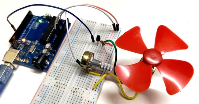
following this guide
https://circuitdigest.com/microcontroller-projects/dc-motor-speed-control-using-arduino-and-potentiometer
what pins on this ESP32-WROOM-32UE can i use
https://www.etechnophiles.com/wp-content/uploads/2021/02/pinout.png?ezimgfmt=ng:webp/ngcb40
 north stream
You'd need pins with PWM output capability, which is probably most of them
hollow pivot
I have no idea if this is the proper channel for this to go but this is where I'm going to be putting it for now. I got everything for my Iron Man helmet wired up after changing it from an Arduino nano to an ESP32 module. I then change the code from the original project to suit my new board. However, now that I have everything hooked up, I finally have movement but the face servo keeps rotating back and forth. When instead both servos should be moving only when the button is pressed. I will be posting my code as well as my pin out as well as a video of what is going on


ServoEasing servoTop;
ServoEasing servoBottom;
const int action_pin = 2;
const int ledPin = 26;
const int potPin = 19;
int location = 31;
int bottom_closed = 107;
int top_closed = 167;
int bottom_open = 20;
int top_open = 20;
int value;
int maxBrightness;
void setup()
{
  pinMode(action_pin, INPUT_PULLUP);
  pinMode(potPin, INPUT);
  servoTop.attach(33);
  servoBottom.attach(35);
  setSpeedForAllServos(190);
  servoTop.setEasingType(EASE_CUBIC_IN_OUT);
  servoBottom.setEasingType(EASE_CUBIC_IN_OUT);
  synchronizeAllServosStartAndWaitForAllServosToStop();
}
void loop()
{
  value = analogRead(potPin);
  maxBrightness = map(value, 250, 750, 0, 255);
  int proximity = digitalRead(action_pin);
  if (proximity == LOW)
  {
    if (location > bottom_open) {
      servoTop.setEaseTo(top_open);
      servoBottom.setEaseTo(bottom_open);
      synchronizeAllServosStartAndWaitForAllServosToStop();
      location = bottom_open;
      delay(10);
      analogWrite(ledPin, 0);
    } else {
      servoTop.setEaseTo(top_closed);
      servoBottom.setEaseTo(bottom_closed);
      synchronizeAllServosStartAndWaitForAllServosToStop();
      location = bottom_closed;
      delay(50);
      analogWrite(ledPin, maxBrightness / 3);
      delay(100);
      analogWrite(ledPin, maxBrightness / 5);
      delay(100);
      analogWrite(ledPin, maxBrightness / 2);
      delay(100);
      analogWrite(ledPin, maxBrightness / 3);
      delay(100);
      analogWrite(ledPin, maxBrightness);
      delay(100);
      }
    }
}
(PS. I know my soldering connections don't look good)
hollow pivot
Is anyone available to help?
north stream
The code looks fine to me, so I don't know what to say.
 cedar mountain
hollow pivot
Is anyone available to help?
cedar mountain
hollow pivot
Is anyone available to help?
I'd probably check to see whether the code thinks that the button is being constantly pressed or not. There may be something off with the button wiring.
hollow pivot
cedar mountain
I'd probably check to see whether the code thinks that the button is being const...
I didn't write the code so I have no idea what does what
cedar mountain
hollow pivot
I didn't write the code so I have no idea what does what
The easiest thing to do is to print out the value of proximity. If things are working normally, it would be "1" except when it changes to "0" for button presses. If something is messed up in the wiring, then it might print a constant "0" instead.
hollow pivot
cedar mountain
The easiest thing to do is to print out the value of `proximity`. If things are ...
How do I do that?
cedar mountain
Makerguides.com
Step-by-step guide to print to the Serial Monitor and format the data to make it more readable and user-friendly!
hollow pivot
cedar mountain
https://www.makerguides.com/how-to-print-to-serial-monitor-on-arduino/
It is constantly printing 0
cedar mountain
So I'd have a closer look at your switch. Normally you'd have one side of the switch connected to the data pin, and the other side connected to ground.
If the button has 4 pins, probably two of them are "one side" and two of them are "the other side". So you might have two of the same side wired up.
hollow pivot
I believe I do. I have one connected to ground and the other connected to D2.
This is the button I'm using. I have black going to ground and red going to D2
 cedar mountain
The other possibility is that there's a short in the D2 wiring, so you may want to have a close look at that solder connection to make sure it isn't touching any other metal.
hollow pivot
cedar mountain
The other possibility is that there's a short in the D2 wiring, so you may want ...
After resoldering and making sure it wasn't a short, it's still produces zeros
cedar mountain
hollow pivot
After resoldering and making sure it wasn't a short, it's still produces zeros
Do you happen to have a multimeter?
hollow pivot
cedar mountain
Do you happen to have a multimeter?
i do
cedar mountain
Cool. So you can double-check things by reading the voltage at D2, and seeing if it changes when you press the button.
hollow pivot
cedar mountain
Cool. So you can double-check things by reading the voltage at D2, and seeing if...
What setting do I put it to?
cedar mountain
"DC volts". If it has a manual range, pick something like 20V.
hollow pivot
cedar mountain
"DC volts". If it has a manual range, pick something like 20V.
It goes from 0.73 to 0 when I press the button
cedar mountain
That's a little weird. Do you know if it's a button with a built-in LED or something like that?
hollow pivot
cedar mountain
That's a little weird. Do you know if it's a button with a built-in LED or somet...
The button does not have a built-in LED.
cedar mountain
Do you have any other different type of button to use? I'm just suspicious that there's something funky about how this one is wired up internally.
cedar mountain
The other thing to check is to disconnect the button and read the voltage on D2 directly. It should idle at around 3.3V, but if it also reads only 0.7V, then it may have been damaged.
hollow pivot
cedar mountain
The other thing to check is to disconnect the button and read the voltage on D2 ...
The D2 was still giving me .73 without anything on it and then I switched it to RXO which is pin 40 because it was giving me 3.3v after hooking both switches up it still gives me zeros. Is there anything special I have to add in the code, possibly an interrupt?
cedar mountain
You should probably pick a different D pin instead of RX0, which is a little special, and changeconst int action_pin = 2;to whichever one you use.
hollow pivot
cedar mountain
You should probably pick a different D pin instead of RX0, which is a little spe...
I switched it to the opposite side of the board and that seemed to fix everything
cedar mountain
hollow pivot
I switched it to the opposite side of the board and that seemed to fix everythin...
Excellent! That's an unusual type of difficulty to run into, so good work chasing it down. 👍
hollow pivot
cedar mountain
Excellent! That's an unusual type of difficulty to run into, so good work chasin...
Well thank you for helping me figure this out. I kid you not. I have been staying up late all week and doing this in my free time in order to figure this out
cedar mountain
hollow pivot
Well thank you for helping me figure this out. I kid you not. I have been stayin...
Heh heh, well hopefully you can sleep soundly tonight for a change. 😴
 modest pine
Hi all!
I’ve spent the last few hours banging my head, trying to decipher this PCB inside of a children’s toy I’m hacking to use as a button panel w/ a microcontroller.
When the toy itself is on, I can short any of the yellow, green, or blue points marked here on the PCB with the red circled trace and it will trigger said button for the toy.
On my microcontroller, however, digital inputs don’t seem to work and are always detected as low voltage. (for reference, each one of these colored points is connected to a different pin on my XIAO nrf52840, and the circled red is connected to GND)
I tried using analog read in desperation and found that when the button is pressed, voltage goes to zero. When up, voltage hovers around ~0.3v.
Any ideas as to what I’m missing here? I’m not an EE and feel like I’m missing something super obvious.

when i use my multimeter in continuity mode across, for example, blue and red here, and press the button, it doesn't beep, but displays ~100 ohms instead
modest pine
i'm realizing now that i might need to cut these other connections i see the device making, marked in purple...
 livid osprey
modest pine
Hi all!
I’ve spent the last few hours banging my head, trying to decipher this ...
livid osprey
modest pine
Hi all!
I’ve spent the last few hours banging my head, trying to decipher this ...
Did you enable pull-ups on your xiao’s digital inputs?
modest pine
yes!
orange_button.switch_to_input(pull=Pull.UP)
purple_button.direction = Direction.INPUT
purple_button.switch_to_input(pull=Pull.UP)
blue_button.direction = Direction.INPUT
blue_button.switch_to_input(pull=Pull.UP)
(using circuitpython, assuming i'm doing that correctly)
 pine bramble
Hey all,
What stepper motor can I use that I can control from an Arduino that can lift say 15kg?
Thanks all.
I found this
https://amzn.asia/d/1Z4Mlna
But idk how easy it would be to control

Greartisan DC 12V 11RPM Turbo Worm Geared Motor High Torque Turbine Worm Gear Box Reduction Motor 6mm Shaft JSX950-370
 opal iris
Hi, i am trying to simulate my arduino project in protieus 8. I wanted to add 5v submersible water pump and a 12v dc solenoid valve. I am not getting the library for that. Can someone please help me with this?
 slate pebble
Hello, I need to store data "permanently" on the seeed xiao nrf52840. And I can't seem to find any working libraries. I don't use the mbed soft version just the"normal one" because the bluefruit lib works very nicely :). Did I missed something? has anybody succeed this?
elder hare
so im messing around with the ESP32-HUB75-MatrixPanel-I2S-DMA library for my 4 x 64x64 panels and i need to use the VirtualMatrixPanel class for this
at the top i have #include <ESP32-HUB75-MatrixPanel-I2S-DMA.h> but im given the error
identifier "VirtualMatrixPanel" is undefinedC/C++(20)
'VirtualMatrixPanel' does not name a type; did you mean 'MatrixPanel'?
the code
#pragma once

#include <Arduino.h>
#include <ESP32-HUB75-MatrixPanel-I2S-DMA.h>

MatrixPanel_I2S_DMA *matrix = nullptr;     // placeholder for the matrix object
VirtualMatrixPanel *virtualDisp = nullptr; // placeholder for the virtual display object
scratch that! i just read on the github that now i have to add #include <ESP32-VirtualMatrixPanel-I2S-DMA.h>
elder hare
not matter what code i upload my ESP32 crashes
rst:0x1 (POWERON_RESET),boot:0x13 (SPI_FAST_FLASH_BOOT)
configsip: 0, SPIWP:0xee
clk_drv:0x00,q_drv:0x00,d_drv:0x00,cs0_drv:0x00,hd_drv:0x00,wp_drv:0x00
mode:DIO, clock div:2
load:0x3fff0030,len:1184
load:0x40078000,len:12784
load:0x40080400,len:3032
entry 0x400805e4
why?
north stream
pine bramble
Hey all,
What stepper motor can I use that I can control from an Arduino that ca...
The amount a motor can lift depends on the length of the lever arm (or, equivalently, the diameter of the pulley), as well as any intervening gear trains. The motor you linked to appears to be a brushed DC motor, not a stepper motor, but stepper motors are mostly used for positioning, not lifting things, unless you want to raise things by specific amounts without other measuring/feedback mechanisms. Assuming it is a brushed DC motor, it's normally just on/off control, but you can get in-between behaviour by PWM modulating the on-off signal. Since motors are inductive loads, you need circuitry to protect against the inductive spikes they generate.
pine bramble
north stream
The amount a motor can lift depends on the length of the lever arm (or, equivale...
I am planning on measuring things without feedback systems
Nema 23 Stepper Motor 4.2A 3.0Nm (425oz.in) 100mm Length for CNC Mill Lathe Router https://amzn.asia/d/guGGlQo this is the new one I am looking at

This is the most powerful Nema 23 stepper motor available. With 1.8 deg step angle (200 steps/revolution). Each phase draws 4.2A, allowing for a holding torque of 3.0Nm (425oz.in). Specifications: Manufacturer Part Number: 23HS45-4204S 57x100 Step Angle: 1.8 Holding Torque: 3.0Nm(425oz.in) Rated ...
hollow pivot
I don't know if this is an Arduino question but I am coding with Arduino.
Is there a way to make a servo spin in reverse ?
cedar mountain
hollow pivot
I don't know if this is an Arduino question but I am coding with Arduino.
Is th...
"Servo" is a little vague. Can you clarify what kind of motor you're driving? A normal servo would move to an angle, not spin at all per se.
hollow pivot
ES08MA
cedar mountain
Yeah, that seems to be a "move to the commanded angle" servo.
hollow pivot
cedar mountain
Yeah, that seems to be a "move to the commanded angle" servo.
How do I get it to go in the opposite direction then?
cedar mountain
hollow pivot
How do I get it to go in the opposite direction then?
What is it doing now? Turning to an extreme position and then stopping? Or spinning forever?
hollow pivot
Nothing is wrong besides the position I need it to be in. I just needed to rotate. Maybe 10 degrees opposite. Every time I set it to negative 10 it doesn't move
cedar mountain
Typically you command an absolute angle, like 0-180, not relative to where it is now.
hollow pivot
cedar mountain
Typically you command an absolute angle, like 0-180, not relative to where it is...
Oh. I think I understand
hollow pivot
cedar mountain
Typically you command an absolute angle, like 0-180, not relative to where it is...
Then how can I get it to rotate towards the green arrow. When I set it to go 10 degrees it rotates towards the yellow arrow
 cedar mountain
It is probably starting from 90, so try commanding like 160 to go the other direction.
hollow pivot
cedar mountain
It is probably starting from 90, so try commanding like 160 to go the other dire...
Setting it to 160 causes both servos to stop moving
elder hare
effects.h
in here i have this
#pragma once

#include <Arduino.h>
#include <ESP32-VirtualMatrixPanel-I2S-DMA.h>
#include <FastLED.h>
#include "config.h"

uint16_t XY16(uint16_t x, uint16_t y)
{
    if (x >= VPANEL_W)
        return 0;
    if (y >= VPANEL_H)
        return 0;

    return (y * VPANEL_W) + x + 1; // everything offset by one to compute out of bounds stuff - never displayed by ShowFrame()
}
there is red underline under VPANEL_W and VPANEL_H but these are found in the #include "config.h"
// Virtual Panl dimensions - our combined panel would be a square 4x4 modules with a combined resolution of 128x128 pixels
#define VPANEL_W PANEL_RES_X *NUM_COLS // Kosso: All Pattern files have had the VPANEL_W and VPANEL_H replaced by these.
#define VPANEL_H PANEL_RES_Y *NUM_ROWS //
so why
identifier "VPANEL_W" is undefinedC/C++(20)
'VPANEL_W' was not declared in this scope
 inland gorge
elder hare
`effects.h`
in here i have this
```c++
#pragma once
#include <Arduino.h>
#inclu...
inland gorge
elder hare
`effects.h`
in here i have this
```c++
#pragma once
#include <Arduino.h>
#inclu...
looks like PANEL_RES_X or NUM_COLSis not defined. where is those supposed to come from?
elder hare
inland gorge
looks like `PANEL_RES_X` or `NUM_COLS`is not defined. where is those supposed to...
they are defined and declared in #include "config.h"
inland gorge
elder hare
they are defined and declared in `#include "config.h"`
and they're declared above VPANEL_W? (hard to debug without seeing the code you're talking about)
elder hare
inland gorge
and they're declared above `VPANEL_W`? (hard to debug without seeing the code y...
i found the problem! i dont want to talk about it BUT.... i had for some godly reason included effects.h in config.h and config.h in effects.h 😅 👍
hollow pivot
Why are my servos making this noise?
cedar mountain
hollow pivot
Why are my servos making this noise?
Best guess is that they're having a little trouble holding the weight against gravity, so they're needing to periodically re-engage the motor a little to maintain their position as they drift off the target angle.
 spare sun
Hello there!
I bought an MKR Zero a while back now, and long story short I borked the microcontroller. It would still function (at least as far as all the functionality I was using at the time) but would rapidly heat up, I'm quite certain I just wasn't paying attention when plugging something in, and was only a matter of time before it completely killed itself. Given that I've got a solder rework station, I bought just the SAMD21G18A and replaced it, but now I seem to be having some trouble getting the replacement chip to do what I want.
I can use openOCD with a raspberry pi to connect via SWD to the SAMD, and it does successfully connect, but when going to flash the bootloader with
at91samd bootloader 0
reset halt
flash write_bank 0 samd21_sam_ba_arduino_mkrzero.bin
at91samd bootloader 8192
reset run
I don't get the functionality I expect. The arduino doesn't show up in Device Manager or the Arduino IDE after connecting to my computer, and the built in led on the board flashes in a manner that I don't see much pattern in, being quite rapid and fairly sporadic, as well as very dim (the LED is not fried, I temporarily swapped back to the old MCU just to be sure that it wasn't a board issue)
I've also tried just the blink example, but that gives me a hard fault in the openOCD log, which I've found references to in some forum posts, so it seems like that might just be a bug with arduino atm?
Not sure, but I've tried what feels like a million different ways to flash this thing, tried lots of different examples, and I'm at my wits end. I can't seem to find anything online that's similar to my issue.
Any and all help I will appreciate, and let me know if there's any more information I should provide.
north stream
spare sun
Hello there!
I bought an MKR Zero a while back now, and long story short I bor...
Did you unset the BOOTPROT fuse? Does it appear as a mass storage device when connected to a computer?
I'm not sure if 8192 is the address you want, I think the bootloader for the SAMD21 goes at 0 and the application goes at 0x2000 (8192) [or 0x1000 if only using one I/O interface]
spare sun
north stream
Did you unset the BOOTPROT fuse? Does it appear as a mass storage device when c...
From what I understood, at91samd bootloader 0 sets the size of the protected area to 0, and is the same as setting the fuse to 0x7, and vice versa at91samd bootloader 8192 would protect the newly written bootloader. It would seem I'm mistaken? I've not seen another way to unset that fuse with openOCD's tools (not sure how familiar with them you are)
No, it doesn't show up as anything when plugged into a computer. My understanding on this was that since the MKR Zero's USB port is directly connected, more or less, to the chip, if the USB CDC code isn't running, there simply won't be anything to recognize, and the bootloader is supposed to have this code in it as well as the normal sketches.
spare sun
north stream
I'm not sure if 8192 is the address you want, I think the bootloader for the SAM...
hmm... so you're saying at91samd bootloader sets where the bootloader begins? and that it should end before 8192 (so 8191?)
Regarding the protection, with that command set to 8192 and attempting to write, I get the same NVM error I've seen a lot online related to the BOOTPROT fuse, when it's set to 0, that error goes away and it seems to flash properly. (The code doesn't work, but the flash and verify sees nothing wrong)
spare sun
        Show or set the bootloader size, stored in the User Row. Please see
        Table 20-2 of the SAMD20 datasheet for allowed values. Changes are
        stored immediately but take affect after the MCU is reset.
  at91samd chip-erase
        Erase the entire Flash by using the Chip-Erase feature in the
        Device Service Unit (DSU).
  at91samd dsu_reset_deassert
        Deassert internal reset held by DSU.
  at91samd eeprom [size_in_bytes]
        Show or set the EEPROM size setting, stored in the User Row. Please
        see Table 20-3 of the SAMD20 datasheet for allowed values. Changes
        are stored immediately but take affect after the MCU is reset.
  at91samd nvmuserrow [value] [mask]
        Show or set the nvmuserrow register. It is 64 bit wide and located
        at address 0x804000. Use the optional mask argument to prevent
        changes at positions where the bitvalue is zero. For security
        reasons the lock- and reserved-bits are masked out in background
        and therefore cannot be changed.
  at91samd set-security 'enable'
        Secure the chip's Flash by setting the Security Bit. This makes it
        impossible to read the Flash contents. The only way to undo this is
        to issue the chip-erase command.

This seems to corroborate my initial thoughts on how the command worked
I'm pretty sure (mostly) that's not my issue...
spare sun
This is quite puzzling to me. I might just need to go all the way down the rabbit hole to find my answer, it just doesn't seem like it should be this difficult.
spare sun
I've no clue if it matters, but the written size and verified sizes are different
> flash write_image erase unlock samd21_sam_ba_arduino_mkrzero.hex 00000000
Adding extra unprotect range, 0x00001a00 .. 0x00003fff
auto erase enabled
auto unlock enabled
wrote 6656 bytes from file samd21_sam_ba_arduino_mkrzero.hex in 2.865152s (2.269 KiB/s)

> flash verify_image samd21_sam_ba_arduino_mkrzero.hex
verified 6408 bytes from file samd21_sam_ba_arduino_mkrzero.hex in 0.671973s (9.313 KiB/s)
perhaps that's just the difference that the hex formatting makes?
spare sun
I simply don't understand
if it writes the code without issue
and it verifies the code without issue
what could possibly prevent the code from working?
It's not like the code itself is unusual... it's just the default bootloader
I've got to be overlooking something somewhere, I just don't know what
The further I'm looking into this the more it seems like it should work
 brittle bluff
I'm using the adafruit flora color sensor which returns rgb values as uint16_t values.
after a bit of debugging, I discovered my comparison function is broken.
  double sum = sq(ri-rf) + sq(gi-gf) + sq(bi-bf);
  Serial.print("yo:");
  Serial.print(ri);Serial.print("-");Serial.print(rf);Serial.print("=");
  Serial.print(ri-rf);Serial.println("");
  Serial.print((ri-rf)*(ri-rf));Serial.print("~");Serial.print(sq(ri-rf));

  Serial.println("");
  return sqrt(sum);
}```
is returning
```yo:184-1024=64696
For some reason and I have no idea why it's failing to do the subtraction first. Any ideas?
cedar mountain
brittle bluff
I'm using the adafruit flora color sensor which returns rgb values as uint16_t v...
All of your variables are unsigned types, so negative values are wrapping around to numbers near 0xFFFF. If you want a signed difference, you may need to cast them to int16_t.
brittle bluff
Can I just set them as int16_t in the function to cast them?
cedar mountain
I think that would work, though it might be somewhat confusing to people reading the code if the original values are really 16-bit unsigned.
brittle bluff
okay so casting them as int16_t worked for the subtraction but the square is returning all sort of wrong
-6871~-6871
845**2 does not equal 6871 and I think I'm unlearning math at this point lol
cedar mountain
What kind of type is sq() defined to return?
845*845 = 714025 = 0x000AE529, so if it was being truncated to int16_t, that would be 0xE529 = -6871.
If you're squaring a 16-bit number, you need 32 bits to hold the full range of results.
 timber goblet
did you ever find out mate?
north stream
Looks like this block transfer call is the fast one https://github.com/earlephilhower/arduino-pico/blob/master/libraries/SPI/src/SPI.h#L39
livid osprey
timber goblet
did you ever find out mate?
It should already be integrated into the arduino core. I’m running a 320x240 ili9342 at 12fps with full frame buffer sends, which shouldn’t be possible without this fix…

 green reef
hey ! I got a bunch of these srd-05vdc-sl-c relay modules... just wnder if there are any prototype boards I can order to use them ?
the pins seems to be misaligned to be used with a standard protoyype borard?

 plain lintel
i cant seem to get noinit working with the nrf5r2 adafruit bootloader. does any one have this working?
north stream
green reef
the pins seems to be misaligned to be used with a standard protoyype borard?
Yeah, I think the pins aren't on a 0.1" grid. There are lots of relay boards out there, it may be possible to find a design you could order from one of the board houses that lets you order designs other people make available.
 final yacht
green reef
hey ! I got a bunch of these srd-05vdc-sl-c relay modules... just wnder if there...
final yacht
green reef
hey ! I got a bunch of these srd-05vdc-sl-c relay modules... just wnder if there...
I'm not aware of any. I end up soldering short solid core wires to the leads to use in a breadboard
 inner crest
Hey, I am doing a project that includes a 18V battery, some type of mosfet/transister to transfer the 18V into 5V which is the intake of the Arduino feather, the project also includes an L298N motor controller, and a 12V CIM motor.
My goal is for the Arduino to control the transistor and to act like a switch to turn on the circuit and if there is no arduino, the circuit cannot turn on.
What concepts do I have to understand to order that transistor and how might I get it to work? I think I have a general understanding of the gate, source and drain voltages, but other than that, Digi-key has a confusing order process
 tiny vector
Hello everyone, I'm a beginner Arduino hobbyist and I'm thinking of doing a wearable project that involves Bluetooth LE and a vibration motor wherein through an android app I'd be able to send a command to activate the vibration motor through the bluetooth LE connection. I've done some prior research and decided to use the Flora V3 board and its Bluetooth LE module for the bluetooth connection aspect and the DRV2605L Haptic Controller Breakout to control the vibration. I would just like to ask for help regarding coding of the Flora board itself as I've scoured the forums and have been unsuccessful finding concrete relevant resources that would help my idea come to reality.
north stream
inner crest
Hey, I am doing a project that includes a 18V battery, some type of mosfet/trans...
Basically the circuit you need is known as a "voltage regulator". There are two main types, linear and switching. A linear regulator has the advantage of being simple (you can build one out of a transistor, zener diode, and a couple of resistors), but the disadvantage of being inefficient (it simply transforms the excess voltage to heat, so 18V in and 5V out would yield about 28% efficiency, which is a lot of heat to deal with and shortened battery life due to the wasted energy. A switching regulator is efficient, but more complicated, it works by switching the transistor on and off quickly so it's not dissipating much energy, and adjusting the on/off ratio to produce the desired output voltage.
north stream
tiny vector
Hello everyone, I'm a beginner Arduino hobbyist and I'm thinking of doing a wear...
There's a nice learn guide on how to drive the Haptic controller https://learn.adafruit.com/adafruit-drv2605-haptic-controller-breakout/overview and you may be able to use a phone app such as AdaFruit's "BlueFruit LE Connect" or Blynk.
tiny vector
Is there a way to integrate the app functions needed into a custom android app?
tiny vector
north stream
There's a nice learn guide on how to drive the Haptic controller <https://learn....
Thank you for the suggestions
livid osprey
tiny vector
Is there a way to integrate the app functions needed into a custom android app?
While I’m sure there is, android app development would fall outside the scope of this channel (and my own knowledge unfortunately.) You could try asking in #general-tech or #help-with-projects perhaps?
tiny vector
livid osprey
While I’m sure there is, android app development would fall outside the scope of...
Understood I will do just that thank you for the help
pine bramble
Can the MKR 1010 WiFi power Adafruit LED boards that need 5V DC power supply?
Or will I damage the MKR board by connecting the LEDs?
This LED in specific: https://www.adafruit.com/product/2858
Be the belle of the ball with the NeoPixel Jewel! These NeoPixel Jewels now have 4 LEDs in them (red, green, blue, and white) for excellent lighting effects.This is the Warm White ...
The MKR has a 5V output, but through reading about it, it seems that it's not capable of powering 5V LEDs? I'm Confused
livid osprey
pine bramble
Can the MKR 1010 WiFi power Adafruit LED boards that need 5V DC power supply?
Or...
The mkr 1010’s 5v pin is directly tied to usb 5v. You may be able to power a few LEDs off of this pin, though I’m not sure if the 5V is available when running off a battery. For powering more than one jewel or anything larger than a jewel, I recommend using an external 5V source.
 leaden walrus
@pallid grail yes. am i 2 late?
 pallid grail
leaden walrus
<@330227457296957440> yes. am i 2 late?
pallid grail
leaden walrus
<@330227457296957440> yes. am i 2 late?
I asked Liz. 🙂 Basically, I wanted verification that Arduino for the ESP32-S2 Reverse TFT Feather was doing a thing on boot. I found the code that does it, but wanted to make sure I was reading it right, because I was excluding a bunch of warnings from the Pinouts page due to my understanding of it, and wanted to make sure I wasn't wrong. I was not wrong.
leaden walrus
cool. good call. esp since i haven't picked up one of those yet.
pallid grail
It pulls the TFT_I2C_POWER pin high on start.
You no longer need to manually do it in Arduino.
leaden walrus
yah, shouldn't. it's been added into the BSP, so is "on" by default.
pallid grail
I need to get Eva to update all the guides that say it's manual. Limor updated all of them to be automatic. But we haven't gone back and updated the guides to reflect that. I mean, it doesn't hurt to pull it high in code too, but still.
north stream
Limor is like that, wants things to be as smooth an experience as practical, so beginners won't get frustrated, and more experienced people can have a simpler flow.
leaden walrus
@pallid grail yep. it's a temporary issue thing. like for the reverse tft - it's been added to the BSP, but has not been released yet. so the only way (right now) to use it is via a manual BSP install. once espressif makes a new release, then it's back to normal.
here's the PR that added it for general ref:
https://github.com/espressif/arduino-esp32/pull/7794
leaden walrus
up to espressif
leaden walrus
just whenever they want to make a new BSP release
pallid grail
Ah
leaden walrus
it's like with core circuitpython
tons of PR's get merged between each release
when/where to draw the line on a release is up to CP dev team
dusky compass
im not sure if this is question for this channel. After uploading code to mcu, i cant boostsel+reset
no matter how many time i press reset button
🤔 did i brick my mcu?
leaden walrus
@dusky compass which board?
dusky compass
feather rp2040
leaden walrus
unbrickable
unless you crush it with a brick
so probably just something else
are you not getting the RPI-RP2 folder to show up if you hold the BOOTSEL button and press RESET?
dusky compass
yep
dusky compass
nothing
leaden walrus
but it worked before?
dusky compass
yes, before i upload code to it
leaden walrus
and you are currently using the same USB cable, computer, etc?
dusky compass
yes the same 1
dusky compass
only screen
leaden walrus
go ahead and remove that for now
any anything else attached, so it's just feather + usb cable
let's make sure you can get back to ROM bootloader mode
leaden walrus
youre getting RPI-RP2 again now?
dusky compass
yep
leaden walrus
do you know what fixed it?
dusky compass
i have no idea
leaden walrus
ok. well at least it's back now.
and other than physically damaging or electrically shorting things, there is essentially no way to brick that board
it may get in a weird state and seem to be not working, can't upload a sketch, etc.
but should always be able to get back to ROM bootloader and recover from there
dusky compass
thank you
light yacht
hi i was wondering if anyone what the standoff height for the adafruit as7341 10channel spectrometer was ?
leaden walrus
can you clarify what you mean by standoff height?
 stuck trout
A house light switch should work with an Arduino right to act as a switch? Like I'm not going to face some weird resistance of the switch issue?
 tardy iron
stuck trout
A house light switch should work with an Arduino right to act as a switch? Like ...
tardy iron
stuck trout
A house light switch should work with an Arduino right to act as a switch? Like ...
how are you planning to use it? as a GPIO input? as a power switch to that board? mechanical switches often have some minimum current that they "like" to switch, and they get dirty or corrode if they don't see that minimum
stuck trout
tardy iron
how are you planning to use it? as a GPIO input? as a power switch to that board...
As a GPIO input. It seems like the cheapest way to get a larger tactile toggle switch for a Maker Faire project.
tardy iron
stuck trout
As a GPIO input. It seems like the cheapest way to get a larger tactile toggle s...
yeah a line voltage light switch that's meant to switch multiple amps might not work reliably switching 5V at a few milliamps. it might work OK at first, but become flaky or bouncy when it doesn't see its minimum "wetting current" to clean the contact points
stuck trout
tardy iron
yeah a line voltage light switch that's meant to switch multiple amps might not ...
How long do you think that’d take? Any recommendations on big toggle switches?
tardy iron
stuck trout
How long do you think that’d take? Any recommendations on big toggle switches?
how long? it depends on a lot of factors, including environmental conditions. if it works well enough in a prototype, it might be last long enough for Maker Faire. how large a toggle switch do you want? what shape?
 whole saffron
Might there be a way for a Feather Rp2040 to do keyboard input from say a button press?
 solemn cliff
whole saffron
Might there be a way for a Feather Rp2040 to do keyboard input from say a button...
solemn cliff
whole saffron
Might there be a way for a Feather Rp2040 to do keyboard input from say a button...
yep, what else do you want to do with it ? There's ready-made firmware like QMK, using tinyusb HID keyboard in your arduino sketch, or you can use Circuitpython as we have many examples of macropads using it
stuck trout
tardy iron
how long? it depends on a lot of factors, including environmental conditions. if...
I don't know exactly. I'd that flat kind and pretty long. I want something you could easily grab onto. It seems like a lot of toggle switches are small, and I'd like something more like a light switch/ industrial size.
 keen pond
@whole wedge is this one too big?
https://nz.rs-online.com/web/p/emergency-stop-push-buttons/1104566
there are also black ones
Sorry, I'm on the wrong way
tardy iron
stuck trout
I don't know exactly. I'd that flat kind and pretty long. I want something you c...
you could always try it and see. if it seems flaky, try having more current than usual pass through it (use smaller external pullup resistors, etc to have tens of mA instead of the more typical hundreds of microamps of an internal pullup) to "wet" the switch contacts, staying within the allowed input current for the GPIO pins
stuck trout
keen pond
Sorry, I'm on the wrong way
That’s pretty cool but a bit outside my price range 🙂 (looks like it’s 90 usd)
keen pond
@stuck trout what would be controlled by the switch? (Only that I have a idea for my part of my brain wich is responsible for design)
stuck trout
keen pond
<@508990365303439360> what would be controlled by the switch? (Only that I have ...
A big step sequencer so just gpio.
keen pond
I'm I right when I throw a few words in like: audio, lfo, synth...
@stuck trout could it be also a momentary switch? To run your machine?
JM-TM100-BUT is cool
around 12$?!
stuck trout
keen pond
<@508990365303439360> could it be also a momentary switch? To run your machine?
Definitely, i guess I wanted the state to be handled by the hardware but could use a momentary. “JM-TM100-BUT” those are cool!
keen pond
I see. Yes I have to buy one too 😄
in Germany we have those in wet rooms:
https://asvendo.de/media/image/product/116/md/aufputz-lichtschalter-wechselschalter-ip44-anthrazit-grau.png

65 x 75 x 48 mm
... also for line voltages. But I see no special problems to use a about 1000 times to set a gpio with it.
@stuck trout To ensure a safe working, you could let run 100mA over it... But I think it will be not nessesary.
The forces onto the contacts are that strong, they must switch 16 amps for multiple 1000 times.
Ok, I would recommend a new one, so the contacts are fresh and clean
here the link to the switch above: https://asvendo.de/Aufputz-Lichtschalter-Wechselschalter-IP44-anthrazit-grau
Maybe you can find something similar

Aufputz / Lichtschalter / Wechselschalter / IP44 / anthrazit grau, 3,
Der vorliegende Aufputzlichtschalter / Aufputzwechselschalter in der Farbe anthrazit eignet sich ideal für den Innen - und Außenbereich (z B : Hallen, Lager
 spice sparrow
Anyone know where to buy a screw terminal shield and a DIN rail mount for the Arduino Due?
I was able to find some good ones below for the Mega.
https://www.dfrobot.com/product-2574.html
https://www.dfrobot.com/product-2582.html
The shield adopts terminal blocks to secure wires so as to make connections stable and reliable. And multiple 3.3V, 5V and GND ports are provided for easy wiring.
This DIN Rail Mount Bracket provides quick and easy mounting for Arduino, which allows you to conveniently build up your Arduino-related applications.
Turns out I'm stupid, the due and the mega have the exact same board size. Correct me if I'm wrong
 acoustic flume
is it a known thing that a TFT display connected to an ili9341 via spi, the screen response is terrible and slow? even with spi baudrate set to 4294967296? flickering constantly, slow writing to screen... just... bad
livid osprey
acoustic flume
is it a known thing that a TFT display connected to an ili9341 via spi, the scre...
Spi baudrate is capped to the limits of your board, so it’ll be limited by your cpu clock. As for flickering and slow writes, there are means of improving quality somewhat, such as using a frame buffer to reduce flickering. I get around 12fps on a pi pico running 26MHz spi clock at the moment on a similar 240x320 display…
It’s an ili9342, but it’s spi interface and the frame rate in the top right is basically accurate. No visible flickering.
 acoustic flume
livid osprey
It’s an ili9342, but it’s spi interface and the frame rate in the top right is b...
acoustic flume
livid osprey
It’s an ili9342, but it’s spi interface and the frame rate in the top right is b...
133mhz or 62.5mbps on my raspi pico, and im lucky to not get flicker on 4fps
livid osprey
acoustic flume
133mhz or 62.5mbps on my raspi pico, and im lucky to not get flicker on 4fps
Share your code perhaps? I’ve played with pico plus spi displays a bit, so I might be able to offer some optimization tricks to try.
Also spi clock is not the same as cpu clock, pico won’t let me drive spi faster than 26MHz without over clocking haha
 heavy star
Bus clocks are usually different than processor clocks
acoustic flume
livid osprey
Share your code perhaps? I’ve played with pico plus spi displays a bit, so I mig...
im using this lib that i wrote based on the adafruit lib: https://github.com/bizzehdee/pico-libs/tree/master/src/common/ili934x pretty sure that if im struggling to get a decent looking ui at more than 4fps, and you can easily get 14fps, that ive done something wrong in the lib
livid osprey
acoustic flume
im using this lib that i wrote based on the adafruit lib: https://github.com/biz...
You wrote your own library? Adafruit has their own ILI9341 library don’t they?
acoustic flume
livid osprey
You wrote your own library? Adafruit has their own ILI9341 library don’t they?
they do, but its for the arduino platform rather than the native ras-pi pico sdk
i ported the adafruit arduino library to native raspi
livid osprey
Huh. I just used https://github.com/moononournation/Arduino_GFX because I’m actually using an ILI9342…

GitHub
Arduino GFX developing for various color displays and various data bus interfaces - GitHub - moononournation/Arduino_GFX: Arduino GFX developing for various color displays and various data bus inte...
This one does support RPiPicoSPI, so I guess I got lucky haha
 placid hound
Where's a good place to ask about Adafruit GFX?
leaden walrus
here's fine. that's an arduino library.
placid hound
basically, I wanted to ask what's the expected timeframe for a PR review or whom to ask about expediting it
I was working on a tram table recently and learned the hard way that it doesn't support UTF-8 so with some effort I ported other solutions to make it work: https://github.com/adafruit/Adafruit-GFX-Library/pull/414

GitHub
As progress on #200 and #244 seems to have stalled, here is the code, I've used to enable UTF-8 glyphs on an HUB75 RGB LED Panel with Adafruit-GFX-Library.
To test it, I've created a UTF-8 ...
Now I have to reference both the official library and my fork in the PlatformIO config (or install the fork with Arduino IDE) which is less than ideal
leaden walrus
unfortunately, no known timeframe. just whenever a dev can take a look. that repo has a lot of open issues and PRs. and is complex. so it could take some time.
 thorny cedar
Hey there! I'm a newbie here. Can anyone give me a simple rundown of how to connect the microcontroller to a digital device using the RX and TX pins on the Feather M0 Adalogger? I tried using the SoftwareSerial library, but ran into some file problems. Think there might be an easier way? Appreciate any help, thanks!
 quaint nebula
Hey are there any 5V Lithium battery’s I can gun my nano off of for my neopixels?
heavy star
Nope, LiPo standard is 3.7/4.2v — you’ll need a 5v boost converter
quaint nebula
Know any good boost converters?
heavy star
There are a few in the Adafruit store — the PowerBoost 500C and 1000C are good 500mA and 1A options respectively
quaint nebula
I looked up the previous 2 but they were sold out and can’t find them anywhere else
heavy star
The 1000 Basic and MiniBoost are both good and in stock
quaint nebula
Can they be wired into a normal arduino nano or only adafruit trinkets?
heavy star
They work with anything :D just a straight 5v output
tiny vector
Is anyone aware how much a energy an Adafruit Flora Bluefruit LE module consumes while on?
heavy star
Here’s what the datasheet says for the module itself — board power should be similar
 tiny vector
Thank you!
 modern seal
I have found nobody, through Google, using the two of these together... so I'd figure I ask here.
Seeeduino Xiao and the USR-ES1 ethernet module.
I'm currently trying to use the Ethernet3-main library (which was made to specifically work with the USR-ES1) but not having luck making it receive packets I send from the PC.
Has anyone any experience with getting the XIAO to work with Ethernet?
 manic jewel
thorny cedar
Hey there! I'm a newbie here. Can anyone give me a simple rundown of how to conn...
manic jewel
thorny cedar
Hey there! I'm a newbie here. Can anyone give me a simple rundown of how to conn...
The Feather M0 has hardware serial. So, you can use Serial https://www.arduino.cc/reference/en/language/functions/communication/serial/. SoftwareSerial is for pins other than RX/TX.
 quartz furnace
Hello all, need some help with the Feather RP2040 Scorpio with Arduino.

So I am trying to read an external board with Serial, I would use Serial1 , correct ?
And GPIO pins 24 and 25?
 quartz furnace
I thought those pins .. RX TX are on the same as the USB?
I want to make sure I am not on that same Serial
So I thought I needed to find TX1 and RX1
quartz furnace
leaden walrus
should be Serial1. see above for pins.
That was it,,, Thank you! Got it working!
leaden walrus
yep. usb is different. Serial for that.
 elfin thorn
Hi y'all!
I'm running a customized version of the Adafruit Clue Sensor Plotter. We never changed anything about the pressure sensor except for the name, but I'm getting almost two orders of magnitude more than it should be showing (99500+-).
Can someone check the code and see if maybe a value is wrong in there? I've gone through it with a fine tooth comb, but I don't have the knowledge to find it. Thanks so much!
cedar mountain
elfin thorn
Hi y'all!
I'm running a customized version of the Adafruit Clue Sensor Plotter....
Values around 100,000 would be correct if pressure is reported in Pascals. Is that a possibility?
leaden walrus
thorny cedar
manic jewel
The Feather M0 has hardware serial. So, you can use Serial <https://www.arduino....
I'm using this function: "Serial.println(Serial1.readString())" but the output is a weird character: �
leaden walrus
check baud rate
 safe shell
could also be non-ASCII
manic jewel
@thorny cedar Can you provide some details on what you are connecting to?
thorny cedar
manic jewel
<@646386147886628874> Can you provide some details on what you are connecting to...
I made a small app in Flutter and connected it to the board. The library that writes the data to the serial port in Flutter takes a List of Bytes object as input. I tried using the "readBytes" function from this library that was suggested to me but I wasn't successful with it either. Can you suggest a simple code for reading in the Arduino code?
This is my code:
#define CTDSerial Serial1

void setup() {
  // put your setup code here, to run once:
  Serial.begin(9600);
  while (!Serial) {
    // wait for serial port to connect. Needed for Native USB only
  }

  CTDSerial.begin(9600, SERIAL_8N1);
  while (!CTDSerial) {
    // wait for serial port to connect. Needed for Native USB only
  }

void loop() {
if (CTDSerial.available() > 0)
  {
    Serial.println(CTDSerial.readString());
  }
}
The code accesses the "if (CTDSerial.available() > 0)" condition when I send a message from the Flutter app, which means the connection is okay, right? In the Flutter app, I also set up the serial communication the same way as in Arduino:
this.port.BaudRate = 9600;
this.port.ByteSize = 8;
this.port.StopBits = 1;
this.port.Parity = 0;
Is that right?
leaden walrus
try adding a simple banner text print after the serial wait:
  Serial.begin(9600);
  while (!Serial) {
    // wait for serial port to connect. Needed for Native USB only
  }
  Serial.println("Testing CTD serial pass thru.");
just to make sure you are seeing that OK
elfin thorn
@cedar mountain oh, you are correct sir. For some reason I thought pascels were about 1000 at a little above sea level.
Thanks! Glad it's good! 😅
manic jewel
thorny cedar
I made a small app in Flutter and connected it to the board. The library that wr...
Is your app sending ASCII characters?
thorny cedar
manic jewel
Is your app sending ASCII characters?
Yes! "Hello" -> [104, 101, 108, 108, 111]
thorny cedar
leaden walrus
try adding a simple banner text print after the serial wait:
```cpp
Serial.beg...
No output 🙄
leaden walrus
this is with the Arduino IDE and using the Serial Monitor?
leaden walrus
weird. should figure that out.
int count = 0;

void setup() {
  Serial.begin(9600);
}

void loop() {
  Serial.println(count++);
  delay(500);
}
try that maybe?
thorny cedar
It's normal.. 1..2..3..
leaden walrus
ok, so maybe the serial wait isn't working as expected
and just missed the single print
is that your actual sketch code above? looks like it's missing a closing curly on setup()
thorny cedar
267
268
� <- "Hello" command
269
 quick maple
how do I modify the frequency of the ir receiver that came with my arduino?
leaden walrus
that looks like it's working, with just some leading non ascii something
or did you add <- "Hello" command ?
thorny cedar
should've seen "Hello" on that line when receiving the "Hello" string on the serial port
leaden walrus
flutter app may not be sending what's expected
leaden walrus
quick maple
how do I modify the frequency of the ir receiver that came with my arduino?
can you link to info on ir receiver? if it's the kind for TV remotes, it may be fixed
quick maple
give me a sec to find the book for my arduino board
basically my remote transmit on two frequencies one for TV and one for VCR so I'd like to know if it's possible to change something the 2nd receiver of my arduino so that it could get the vcr signal when the switch is flipped to video on the remote
dir /s is going to be a bit slow so dont hold your breath I'll let you know
hum it doesn't show but the manual has a graph for PNA4601M/4608M/4610M the remote is a sony rmt-v402A
the tv buttons work but if I switch to video I dont get the video version of the button just the TV ones. Some docs on github Im trying to find says that the video uses a different frequency and a different pulse length (so I guess the pwm settings would be different)
but it's not clear for me if there is something I can do like amplify the IR signal or transform it like you can do with radio waves with IR
 quick maple
it's optical though right? can't i put a lens in front of it or sand off the crystal?
leaden walrus
not readily finding DS for the 4608M or 4610M variants
they may be different freqs - but all are probably fixed
another example:
https://www.adafruit.com/product/157
quick maple
bah I thought could alter it physically and change the frequency or something since they are so cheap
leaden walrus
same deal. can come in different freqs, but it's part number specific.

this talks about the IR signals:
https://learn.adafruit.com/ir-sensor/ir-remote-signals
to better understand the carrier frequency
these IR receivers are pretty simple - they take care of the first step of decoding - they pull the on/off pulses out of the raw carrier signal
quick maple
there is another thing that isnt correct with my IR receiver
leaden walrus
they don't do any actual decoding beyond that
quick maple
related to pulse lenght or width or someting that I have no control over
so I had to adjust it by waiting 400-500ms before accepting another input
and I cant detect two buttons pressed at once because of this
probably bandwidth?
I wish I could find the docs that was on github again
I was surprised it even worked honestly...
leaden walrus
there's only ever the one signal
two buttons would either be sent back-to-back, or as a special code
quick maple
why do I still get a code in 38 khz even though it's in video mode but I get the tv code?
Could the remote have two IR transmitters?
Like the github doc said another code for play in video mode
leaden walrus
maybe - can try the "look at it with your phone camera" trick
see what LEDs might be showing up with button presses
quick maple
but I still get the tv code when on my arduino when pressing it when the remote is in video mode
hum Ill try to find it and my old code and come back when I do
modern seal
modern seal
I have found nobody, through Google, using the two of these together... so I'd f...
*bump
thorny cedar
leaden walrus
flutter app may not be sending what's expected
Turns out the issue was with the Flutter code itself, but with the serial port setup, which should be done after opening the port and not before.
    this.port = SerialPort(port);
    var config = SerialPortConfig();
    this.port.openReadWrite();
    config.baudRate = 9600;
    config.bits = 8;
    config.stopBits = 1;
    config.parity = 0;
    this.port.config = config;
}
Problem solved. Thanks everyone!
 knotty rover
does anyone have a good btle -> Unity tutorial. I've bought the two main unity plugins for doing btle an android on unity, but I still have a hard time wrapping my brain around how to do everything with gatt, and get data in and out. I'm sorta familiar with firmata, from trying to find a solution, but haven't been able to get to a working setup yet. I've been using old bluetooth with spp up till now, but none of the new super tiny micro controllers support spp anymore, so to make use of them I'm forced into the btle world, which i've put off for years.
I'm really just looking to be able to read analog pin change inputs from the microcontroller, and send the microcontroller a signal from unity to do stuff. that was trivial with spp.
north stream
I haven't used Unity, but I was also sorta familiar with Firmata, but ended up going with the newer Telemetrix in a recent project, as it seemed to have better support these days. Annoyingly, there are several products using the same name, this is the one I ended up using https://mryslab.github.io/telemetrix/
timber goblet
This isn't my project so I don't have the code but he's using c

Is there a reason the letters like lower case g and j and anything that extends down is getting cut off?
qypgj in lower case
north stream
I'm guessing either the typeface doesn't render the descenders, or the glyph painting algorithm isn't using coördinates below the baseline.
 brazen falcon
north stream
I'm guessing either the typeface doesn't render the descenders, or the glyph pai...
brazen falcon
north stream
I'm guessing either the typeface doesn't render the descenders, or the glyph pai...
Or its treating every line as a seperate tile and overwriting the descenders with the next line.
north stream
Good point, that could be too.
timber goblet
timber goblet
This isn't my project so I don't have the code but he's using c

GitHub
Pico display library for the ST7735. Contribute to bablokb/pico-st7735 development by creating an account on GitHub.
 faint gulch
Hey everyone, i'm in desperate need for help. i tried everything and it still does not work. I have to get an adafruit BMP280 sensor to work by tomorrow, and it says it's not detected. Here is my code: ```/***************************************************************************
This is a library for the BMP280 humidity, temperature & pressure sensor
Designed specifically to work with the Adafruit BMEP280 Breakout
----> http://www.adafruit.com/products/2651
These sensors use I2C or SPI to communicate, 2 or 4 pins are required
to interface.
Adafruit invests time and resources providing this open source code,
please support Adafruit andopen-source hardware by purchasing products
from Adafruit!
Written by Limor Fried & Kevin Townsend for Adafruit Industries.
BSD license, all text above must be included in any redistribution
***************************************************************************/
#include <Wire.h>
#include <SPI.h>
#include <Adafruit_Sensor.h>
#include <Adafruit_BMP280.h>
#define BMP_SCK 13
#define BMP_MISO 12
#define BMP_MOSI 9
#define BMP_CS 8
#define BMP280_ADDRESS 0x76
Adafruit_BMP280 bmp; // I2C
//Adafruit_BMP280 bmp(BMP_CS); // hardware SPI
//Adafruit_BMP280 bmp(BMP_CS, BMP_MOSI, BMP_MISO, BMP_SCK);
void setup() {
Serial.begin(9600);
Serial.println(F("BMP280 test"));
if (!bmp.begin()) {
Serial.println(F("Could not find a valid BMP280 sensor, check wiring!"));
while (1);
}
}
void loop() {
Serial.print(F("Temperature = "));
Serial.print(bmp.readTemperature());
Serial.println(" *C");
Serial.print(F("Pressure = "));
Serial.print(bmp.readPressure());
Serial.println(" Pa");

Serial.print(F("Approx altitude = "));
Serial.print(bmp.readAltitude(1013.25)); // this should be adjusted to your local forcase
Serial.println(" m");

Serial.println();
delay(2000);
}
i have vcc connected to 3.3v, grd to gnd, sck to d13, sda to d9, csb to d8, and sdo to d12
cedar mountain
faint gulch
i have vcc connected to 3.3v, grd to gnd, sck to d13, sda to d9, csb to d8, and ...
It sounds like you're following a SPI wiring guide, but your code is expecting the sensor to be connected over I2C.
faint gulch
cedar mountain
It sounds like you're following a SPI wiring guide, but your code is expecting t...
can i fix this without resoldering? bit of a noob, sorry
cedar mountain
You'd want to comment out the first line here and uncomment the third line, most likely:Adafruit_BMP280 bmp; // I2C //Adafruit_BMP280 bmp(BMP_CS); // hardware SPI //Adafruit_BMP280 bmp(BMP_CS, BMP_MOSI, BMP_MISO, BMP_SCK);
faint gulch
cedar mountain
You'd want to comment out the first line here and uncomment the third line, most...
how do i do that? sorry if its a dumb question
cedar mountain
It should end up looking like this instead://Adafruit_BMP280 bmp; // I2C //Adafruit_BMP280 bmp(BMP_CS); // hardware SPI Adafruit_BMP280 bmp(BMP_CS, BMP_MOSI, BMP_MISO, BMP_SCK);The // sequence at the start of the line tells the compiler "ignore this", so which line has and doesn't have that indicates which of three configuration options your code is using.
faint gulch
Ohhhh right
I'll try that
Awesome, it works! Thanks a lot, learn something new every day i guess
now it says my altitude is -200m but ill figure that out
cedar mountain
The altitude will be dependent on the weather ("high pressure" or "low pressure" systems), so that'll mostly be good for relative measurements from a baseline.
faint gulch
alright
this thing will be shot up to approx. 1km height and then read data on it's way down which we will collect in real time using a big antenna
big school project
thanks a lot for the help!
cedar mountain
faint gulch
this thing will be shot up to approx. 1km height and then read data on it's way ...
Hahaha, awesome!
 faint gulch
here i am back again with another question

how to get that local forcase number?
and is it possible to convert the pascal to bar in serial? with a math formula or something?
north stream
faint gulch
I'm guessing that's a typo, and they mean the current barometric pressure from your local forecast
leaden walrus
yep. it should be whatever current sea level pressure is at your location. which may be trickier to determine then you'd think.
more info:
https://learn.adafruit.com/clue-altimeter
north stream
Another way to get that information if you have an airband capable radio, is listen to the broadcast from your local airport and use their station pressure or altimeter setting pressure.
leaden walrus
might be worth (if not already doing) to send back raw sensor pressure in the telemetry. the altitude can always be post processed.
faint gulch
leaden walrus
yep. it should be whatever current sea level pressure is at your location. which...
1038 I think then
 north stream
faint gulch
and is it possible to convert the pascal to bar in serial? with a math formula o...
north stream
faint gulch
and is it possible to convert the pascal to bar in serial? with a math formula o...
Yes, it's an easy formula: 1 bar is 100000 Pascal
leaden walrus
hPa = Pa / 100
faint gulch
north stream
Yes, it's an easy formula: 1 bar is 100000 Pascal
Alright. And how do I put that in the code? Can i just do x x 0.000001 or something?
north stream
Yes, that should work
faint gulch
Nice. Thanks!
north stream
Er, x 0.00001
faint gulch
Whoops, I put one 0 too many 😅
 waxen sun
does an arduino version of the example shown in https://learn.adafruit.com/adafruit-oled-featherwing/python-usage exist

since i want to use the full power of my VL52L4CX without doing, uhhh, this

thats a bit off topic anyways yeah
north stream
waxen sun
does an arduino version of the example shown in https://learn.adafruit.com/adafr...
waxen sun
hmmhm ty
solemn cliff
there's a guide for the GFX library https://learn.adafruit.com/adafruit-gfx-graphics-library
waxen sun
o thats helpful too thankss
 inland prawn
Hello, I have an arduino motor shield (l293D) and nrf24l01 which both require connecting pins 11 and 12 on the arduino uno board. Is there a way I can make one of them function on other free pins?
Or can't I connect both the arduino motor shield and nrf24l01 module using one female to female jumper (maybe 2) to the same 11 and 12 digital pins on the arduino uno?
brazen falcon
You might want to consider the Adafruit motor shield instead, as I remember the official arduino one uses a ton of pins and leaves almost nothing left over.
Whereas the adafruit v2 only uses A4/A5 and optionally D9/D10
inland prawn
brazen falcon
You might want to consider the Adafruit motor shield instead, as I remember the ...
I use the adafruit one but I can't identify whether it's v1 or v2
 north stream
That does not appear to be the AdaFruit one, it looks like the Last Minute Engineering one, which is basically a clone of the Arduino one.
However, I think that board uses a 75HC595 shift register as a simple port expander, it's often used as if it were an SPI peripheral (which would explain the use of pins 11 and 12, which are the SPI MOSI and MISO signals). I think the nRF24L01 can also act as an SPI peripheral. The trick might be to use whatever pins are left as chip select signals, in order to use a shared SPI bus to talk to both of them. However, this is largely guesswork on my part and I'm not sure I'm right (for example, the SPI clock signal is typically pin 13, and I don't know if the 75HC595 is wired up that way)
inland prawn
As of what I've read, this shield doesn't use pin 13

And I also, I didn't quite understand the trick you gave me
north stream
Ah, then perhaps it's not an SPI interface
inland prawn
inland prawn
Also, I want to clarify something. I am not planning to attach the motor shield to the arduino uno to be able to connect the nrf24l01
As of what I understand, m1 uses pins 11 and twelve, m2 uses pins 3 and 4, m3 uses pins 5 and 7, m4 uses pins 6 and 8
Is this correct?
So right now I just want to test m2
I've connected the motor wires and connected pin 3 in the arduino to pin 3 in the motor shield and pin 4 in the arduino to pin 4 in the arduino shield
I've wrote a code, but the 2nd motor doesn't work
Could this be something in the code or just in the wiring between arduino uno and motor shield?
north stream
According to the image you posted, M1 uses pins [4,7,8,12] and 11. M2 uses pins [4,7,8,12] and 3.
inland prawn
Wait so I am required to connect pins 4 7 8 12?
But nrf24l01 also uses pin 12
How can I resolve this
north stream
That depends on what they're using pin 12 for, and how hard that is to change.
inland prawn
My guess is that it is using pin 12 for maybe something related to motor 1 (which uses pin 11). I thought looking at the adafruit motor driver library, I thought it help but the code is too complex for me
north stream
The 4, 7, 8, 12 pins are used by the motor shield to talk to the serial to parallel chip. Since those aren't all SPI pins, I'm guessing they're not using hardware SPI to talk to it, so presumably, you could change pin 12 to some other pin (wire it that way, and change the library to match)
inland prawn
north stream
The 4, 7, 8, 12 pins are used by the motor shield to talk to the serial to paral...
The library code itself? I mentioned it's too large (upto 1000 lines) and actually too complex for me to understand as it uses cpp (I've always used python and nodejs for my normal programming)
inland prawn
I've tried to go through the code, but I haven't found anything that relates to pin 12
north stream
Where is the code for the library you're using?
inland prawn
GitHub
Adafruit Motor shield V1 firmware with basic Microstepping support. Works with all Arduinos and the Mega - Adafruit-Motor-Shield-library/AFMotor.cpp at master · adafruit/Adafruit-Motor-Shield-library
north stream
Ah, the pins are in the header file. It may be the only line you need to change is https://github.com/adafruit/Adafruit-Motor-Shield-library/blob/master/AFMotor.h#L138
inland prawn
OK so after all of this I'll have 3 pins left, I'll have to use 3 motors instead of 4
BTW can I use the 0 and 1 pins?
Or can I make one of my analog pins act as a digital pin?
And thank you so much for your help so far
You really helped me a lot, like really a lot
I am going to have to change the 12 pin to 10
inland prawn
inland prawn
But here pin 10 is used for servo
Should I make any more code changes?
 tardy zealot
Can anyone help decode this? Using ESP32 WROOM
 north stream
inland prawn
BTW can I use the 0 and 1 pins?
north stream
inland prawn
BTW can I use the 0 and 1 pins?
The 0 and 1 pins do double duty as the serial port, so you can only use them if you're not using the serial link to the host.
north stream
inland prawn
Or can I make one of my analog pins act as a digital pin?
Yes, the analog pins work as digital pins as well.
north stream
tardy zealot
Can anyone help decode this? Using ESP32 WROOM
It looks like something called bleRequestData() which in turn called connectToServer() which ended up doing something with memory that didn't work out well (my guess is it tried to free some memory that wasn't marked as allocated)
inland prawn
north stream
Yes, the analog pins work as digital pins as well.
Alright so right now I just removed the whole nrf24l01 module and directly attached the shield onto the arduino uno
And I also uninstalled the library and installed it again to remove any changes I've done
Now the only thing I can do to connect the nrf24l01 back is use the analog pins from 0 to 6
But I've read that they use spi and they must be added in pins 11-13 (which I still don't exactly understand why) but I also read about something called software spi which allows them to be added on any pins
So my question right now is: how can I make the analog pins act as digital pins and use this software spi to be able to connect the nrf24l01 module
north stream
You pretty much answered your own question: set up software SPI to use the available pins, connect the board to those, and arrange for your code to use the software SPI port instead of the chip's built-in hardware SPI (the built-in hardware SPI is why those specific pins are used)
inland prawn
Actually what I was asking is how to this software spi
Any videos/documents or references to it?
north stream
There's this library, but documentation seems a little thin https://github.com/MajenkoLibraries/SoftSPI
inland prawn
north stream
There's this library, but documentation seems a little thin <https://github.com/...
I think this is pretty much self explanatory

^^this
But in my case, I'll use A01, A02, and A03.
 lone agate
I noticed STMPE610 is discontinued. Is there a recommended replacement?
whole saffron
solemn cliff
yep, what else do you want to do with it ? There's ready-made firmware like QMK,...
How would I do this with a capacitive touch sensor
Sorry, I'm doing it in CircuitPython so this might not be the right place to discuss it
inland prawn
Hello
I connected my nrf24l01 module using software spi using analog pins
But for some reason it doesn't seem to be receiving stuff from the other nrf24l01 module
 inland prawn
Is this necessary? Because they were already communicating before
And I didn't use capacitors
Tho there was something in the nrf24l01 setup code which had MAX which I changed to MIN
brazen falcon
It can give you more reliability
quartz furnace
Have a mmWave Radar coming soon from an order …. When looking at the code

Would I just need to create an int called (example) RadarData and then
RadarDate = radar.Bodysign_judgment(dataMsg, 1, 15); ?
I’d like to make an If statement from the results of radar.Bodysign_judgment(dataMsg, 1, 15);
Or would be best in the ‘for loop ‘ to construct the result?
 native dagger
Is there a source online for docs for the adafruit arduino libs? Specifically neopixel?
found it
Is there a way to denote sub sections of a strip of neopixels?
Like if I want to break it into 6 sections that may or may not be contiguous
safe shell
you can use slices, or are you asking if the pixels within a section can be non-contiguous? (I think you'd have to write some abstraction for that)
(sorry, python terminology)
native dagger
Hm. I can probably do what I want with slices, but I'd like to be able to do built in operations from the neopixel library like rainbow or colorWipe on separate sections of the same strip
whole saffron
Anyone know how to do Midi Controlling with a MPR121?
native dagger
Is there an official way to get adafruit boards into the VSCode PlatformIO extension?
 dry quiver
whole saffron
Anyone know how to do Midi Controlling with a MPR121?
dry quiver
whole saffron
Anyone know how to do Midi Controlling with a MPR121?
Looking at the sample code for the MPR121 and MIDI learn guides, you can probably build off the MPR121 sample code and have each "button" run a callback function that sends midi messages when triggered.
Try the Arduino MIDI library. It's pretty robust.
 frail pawn
Hey, im not sure if this is exactly an arduino problem but since im using the IDE I thought I would ask here, I have an ESP32 feather v2 that I am trying to connect to my pc, but my pc doesnt seem to recognise it at all? I have tried installing both possible drivers suggested but my pc essentialy doesnt recognise it, no com port shows up etc. If there is a better place for this question please let me know!
leaden walrus
verify USB cable is good
frail pawn
Works fine with other devices
leaden walrus
moves data?
leaden walrus
just to double check feather, it's this one?
https://www.adafruit.com/product/5400
frail pawn
i think itsd the non stemma one im not sure
let me check
no iwas wrong, it is thast one
leaden walrus
does PC react at all when plugged in?
leaden walrus
anything attached to the feather other than USB cable?
frail pawn
nothing at all
leaden walrus
weird. it should do something when connected. even if drivers aren't working. PC should see the USB-to-serial adapter.
frail pawn
ok so on the board itself
leaden walrus
have you tried other USB cables?
frail pawn
im getting a small red LED flashing to the left of the USB connector, then the neopixel goes GREEN, then cycles a couple of colours, then GREEN, cycle again, and the led next to the cable stops flashing when it goes green
nmot sure what the default demo is so thought i would mention
leaden walrus
that's probably shipped firmware running on the ESP32
frail pawn
right, i ave tried two cables both of which work with other devices
leaden walrus
and indicates the feather is at least getting power
do you have access to another PC as another check?
frail pawn
i do, give me 2 minutes
leaden walrus
simple check - just plug feather in and see if it reacts. like "something plugged in" ding.
no need to install drivers
leaden walrus
🙂
frail pawn
right, nothing on that one either
leaden walrus
weird. acting like there's a hardware issue. like a connection issue on the USB pins.
please post this in the forums along with a photo of the feather:
https://forums.adafruit.com
can ping me with forum link once up
leaden walrus
feather topic is fine:
https://forums.adafruit.com/viewforum.php?f=57
frail pawn
would you prefer images directly embedded at meh quality or a link to an imgur album for example
leaden walrus
imgur link is ok
 small thorn
I'm having a terrible time getting around screen flicker on an Adafruit 1.9" 320x170 Color IPS TFT Display - ST7789 using Adafruit_GFX library on an Arduino Mega 2560 Pro mini. In a nut shell, I have a pretty static graphics display onscreen at all times except I want to display a number that can increment. No matter what method I use to display the numbers it either flickers terribly or else the canvas feature paints the numbers in a painfully slow manner.
My specific application needs to mimic a 7-segment display so I had to create and import a custom 36pt font based off the Segment7 font found online. Because of this, I don't get the benefit of the digits painting over themselves using black background color like you get with the built in mono spaced fonts (even though my custom font happens to be a monospaced font).
Is this display and library just that slow or are there ways to speed up the redraws when using a canvas? I'll be glad to share code if someone is willing to help. Thanks!
frail pawn
Well that help was quick, sadly i ordered the board through a UK supplier so I may have to contact them haha
Thanks for your help!
 mild cave
small thorn
I'm having a terrible time getting around screen flicker on an Adafruit 1.9" 320...
mild cave
small thorn
I'm having a terrible time getting around screen flicker on an Adafruit 1.9" 320...
According to adafruit product page
so i would make sure that it is using hardware spi
 small thorn
mild cave
According to adafruit product page
so i would make sure that it is using hardwar...
small thorn
mild cave
According to adafruit product page
so i would make sure that it is using hardwar...
I saw that when wiring up and followed the basic learning guide here (https://learn.adafruit.com/adafruit-1-9-color-ips-tft-display/arduino-wiring-test). Per their instructions I used pin 52 SCK and pin 51 MOSI. So I believe I'm using the boards built in SPI hardware pins correct?
mild cave
small thorn
I saw that when wiring up and followed the basic learning guide here (https://le...
yeah, looks like you are using correct pins
I am not too sure , but maybe the arduino is not fast enough ? 🤷♂️
or maybe ur other code is taking too long ?
small thorn
mild cave
yeah, looks like you are using correct pins
I am still hoping someone can help me here with the stock GFX library, but after I posted here, I searched the regular Adafruit forum and found this jewel! https://forums.adafruit.com/viewtopic.php?p=960462&hilit=gfx+canvas#p960462 Copying in gammaburst's fastDrawBitmap() function, it COMPLETELY SOLVES the issue and my LCD seven segment display works absolutely flawlessly! I am trying to figure out why this was never rolled into the GFX library to take the place of their method which apparently draws each pixel, one at a time which must be why it is so incredibly slow.
mild cave
Great
 gray owl
Just jumped in.... Hackoholic that sounds great!!!
small thorn
mild cave
Great
I just went back to the forum where I found this and see that gammaburst only posted his new fastDrawBitmap() function (4) days ago! Hoping @heady sparrow or others see his work and are able to roll it into the GFX library seeing as it so **dramatically **improves the ability to rapidly update canvas items that use custom fonts.
 heavy star
Assuming you only need up to 1A, and have undervoltage protection if you’re using a LiPo battery, yeah, it’s a great option
quick maple
Im so confused by "arduino"
like if a board uses a atmel used on an arduino and is arduino ide compatible isn't that an arduino ?
ie: quack like a duck, act like a duck but doesn't look like a duck except for the head and the beak ?
 gilded swift
quick maple
like if a board uses a atmel used on an arduino and is arduino ide compatible is...
gilded swift
quick maple
like if a board uses a atmel used on an arduino and is arduino ide compatible is...
Arduino really only refers to the boards manufactured by Arduino and the IDE itself
Though it has become synonymous with anything that can be programmed through Arduino
heavy star
I detailed the specifics already XD #general-tech message
heavy star
First half was specifically about Arduino vs. Arduino compatible
gilded swift
Phew I panicked there for a minute
quick maple
someone told me this week that my zumo 32u4 robot is basically the same thing as the arduino version (which is either a uno r3 or leonardo) when I told them Id like to upgrade it with a mega 2560 which didn't make sense for them
and I'm still confused by that statement
quaint nebula
Also can you run two neopixel animations on one board
quick maple
but even if it was very similar to a leonardo it's still very underpowered vs a mega 2560...
quaint nebula
Like one animation running through one data pin and another one on another data pin
quick maple
or a teensy 4.1...
heavy star
quaint nebula
Also can you run two neopixel animations on one board
Depends on how many NeoPixels and what board
quaint nebula
Arduino nano
quick maple
ok for the context I asked how I could upgrade my 32u4 and I said I should have bought the arduino version and they said the above
but the atmel is just the brain, the whole body make a leonardo not just the brains, right ?
solemn cliff
same chip, same features
number of pins will change possibly
what's the zumo 32u4 ?
quick maple
a tracked robot with some onboard peripherals
solemn cliff
oh it works like a shield
quick maple
but I feel like I wasted money because it uses 2-56 screws and the very low 8kb of RAM
no it's preprinted board
peripherals are soldered directly on the board so some pins can't be used even if they are physically available
because internally they are soldered to the board and the chip
solemn cliff
ah it's not the shield model ok
heavy star
quaint nebula
Arduino nano
Definitely depends on how many pixels
quick maple
so Im basically trying to evaluate wheter to spend more money on this or just give up and change the board to a teeny 4.1 or grand central m4 and re-procure every drivers/sensors on it
but 8kb isnt a great bit of capability for sure
quaint nebula
One is 42 neopixels and the second is 14
quick maple
I know I can sorta workaround that by using a better board and using the 32u4 as a sort of language interpreter kinda like lego mindstorms or logo
but I`d rather have a board with 8mb+ of RAM, flash memory for data and itself being able to process images and navigate
solemn cliff
yeah you can use the 32u4 as a coprocessor for a bigger one
quick maple
tbh Im mostly scared about losing the hall sensor and the quadrature rotary encoder embedded in the motors because the motors are 2/3 of the cost of the whole thing... and the hall sensor right over them
solemn cliff
kind of like Adafruit's seesaw and Crickit
quick maple
this is what has stopped me so far because the sensors are really basic otherwise or not for my planned use
solemn cliff
the shield model offers more flexibility and can probably work with a board like a Metro which gives you plenty of choice https://eu.robotshop.com/fr/products/zumo-tracked-robot-kit-arduino-751-hp-motors
but since you already have a thing, I would rather find a way to use it
quick maple
so you'd go with say carry a second pack of batteries as a trailer to use a better board with it that process stuff and output a command like an interpreter to it ?
ie: like FWD 30 for forward 30cm so it doesn't need to do any processing just turn on the engines to roll 30cm?
for context it carry 4 AA batteries mostly used for the engines. The 32u4 can't power another board like a teensy 4.1 or grand central so I'd need separate batteries for that or a really long usb cable
solemn cliff
powering from the same source should be possible, but maybe not easy
quick maple
last about 1h with the engines going on at a normal rate, 10h without engine at idle
I estimate that a board like a mega because it doesnt have a wireless / wifi would probably last 30 mins with engines
solemn cliff
just don't send the 5V directly into a 3V board's pins
quick maple
a more capable one with wireless probably not more than a few minutes
solemn cliff
hmmmm
quick maple
I heard that my qt py esp32-s2 are big power hogs apparently with wireless on
and will use their full 950mA
and something far more speedy like m4 grand central and teensy 4.1 in the hundreds of mhz would probably be far worse
I'd expect they burn throught batteries like a pi2b+
solemn cliff
it can have larger spikes, but an ESP32 is more like 50-150mA I believe, and that's wifi, it might be lower in BLE mode for example
Don't quote me on that though, I'm not sure, this depends of so many parameters
quick maple
a last alternative, but far more complicated would be to use an expensive trasmitter like taranis or the opentx drone control protocol and use a receiver to uart module and run some intelligence on the transmitter so that in effect it's a "semi-automatic" system that send and receiver
but that is probably actually much more complicated than it sounds
anyway I think wireless is a dead-end
because this thing can still go at 15mph and need to react "fast"
don't have time to wait for a tcp packet or something similar to travel back and forth and adjust danger detection with the "relativity" of the motion vs the wireless signal speed
hollow pivot
I just got the elligoo nano and it has the ATmega328P and CH340 chip instead of FT232 and it says I need to install the driver first. How do I do that?
I believe that is the main reason why my servos are not working
solemn cliff
I believe this guide shows how to install the WCH drivers
https://learn.adafruit.com/how-to-install-drivers-for-wch-usb-to-serial-chips-ch9102f-ch9102
this would be the direct link ?
http://www.wch-ic.com/downloads/CH341SER_ZIP.html
with different OSs listed
hollow pivot
I am about ready to give up. What is going on here
quick maple
hollow pivot
I am about ready to give up. What is going on here
Sounds like you are powering your servos with your arduino instead of an external power source like batteries and expecting it to works ?
or a variation of this ?
or you have some motor driver shield in there ?
hollow pivot
I have no idea of what any of that means.
But I have now eight AAA batteries powering it and it seems to be working fine
quick maple
hollow pivot
I have no idea of what any of that means.
But I have now eight AAA batteries po...
I'm trying to explain to you what it going on
and that it is normal that you can't power 6 servos from your arduino as they need about 400-750mA each
servo are usually arduino driven but not arduino powered
hollow pivot
I only have two servos
And was plugged into my computer as well as having six additional AAA batteries
quick maple
and when you disconnect/switch off the 6 AAA batteries the servos don't work anymore ?
hollow pivot
Yes. In the instructions. It said it only needed four AAA batteries
quick maple
instructions for the nano or the helmet ?
hollow pivot
The helmet
quick maple
ok so it would also work with a single 9V battery too, but not for long, could also use 6 AA batteries
the issue is that your servos need 400 to 800mA and there is two of them + the arduino which might need up to 500mA
but your usb plug provide 1000mA
so it quickly runs out
that is why it turns off without the batteries
hollow pivot
6 didn't work. I needed the 8 so I would need a 12v source
This project has been nothing but roadblocks and fails. I have been working on the electronics for over two weeks and all I get are fails
 wide shadow
Using EyeSPI and the MemCS pin, how does one access the display RAM?
 deft flame
Can anyone give me some guidance on applying change of a usb register of samd21 with arduino? So far I tried just rewriting it which didn’t have effect, and my reset efforts resulted in usb being bricked, can’t figure out how to apply the changes.
north stream
What are you trying to do? The Arduino IDE will let you configure the USB port for Serial, HMI, etc.
deft flame
north stream
What are you trying to do? The Arduino IDE will let you configure the USB port ...
I want to try to configure it for audio, I found two mentions online of it being done with this mcu so I believe it possible. But even though I have experience with registers I am new to usb stuff and it’s more complicated, didn’t even figure out how to change device name and such, and especially not these more in depth thigns
But that’s kinda different to my initial question as I figured that out, but still about samd21 usb
elfin thorn
Hi y'all! I'm working with the MLX90640 on the Clue using the MLX90640 ArcadaCam sketch. At first I thought it was a hardware issue, as I was getting zero data from the serial monitor nor the temp colors on the screen (Screen is on but blank).
When I test the hardware in Circuit Python, everything works beautifully (Circuit Python 8.0.2), but none of the Arduino sketches are working; Adafruit's Learning Guide, the GitHub repository (Adafruit's), and the sketch example in Arduino.
It was working with no issues several months ago but now I can't figure this out. Thanks!
I just uninstalled and re-installed the libraries but that had no affect.
 sacred ivy
Is there an arduino or variant of, that has an integrated touch screen in it?
Or is there an TFT screen shield for the Arduino?
heavy star
Currently out of stock, but there is a shield https://www.adafruit.com/product/1651

Spice up your Arduino project with a beautiful large touchscreen display shield with built in microSD card connection. This TFT display is big (2.8" diagonal) bright (4 white-LED ...
sacred ivy
I was afraid of that lol
solemn cliff
the pyportal is in stock
and the pyportal titano but not the pynt
not a cheap device what with the SAMD51 and stuff
wide shadow
sacred ivy
I was afraid of that lol
I prefer the Capacitive touch variant. I have both as a shield with presoldered pins.
sacred ivy
I see that there is a a ESP-32 with a TFT screen but it may be too much
not price wise, just over kill
I also need mounting holes (I think). I need to find examples of how people attached displays to a wall/enclosure
solemn cliff
yeah there are ESP32 with touch displays like the ESP box or the "ESP32-4827S043" and the "ESP32-2432S028R" or whatever they're called and similar ones, but you know if the price is right, overkill is just a bonus 😉
 summer aspen
I accidentally uploaded broken code to my brand new adafruit 32u4 adalogger, and when trying to do the steps for 'repairing' it the connection always hangs at Waiting for upload port... when the bootloader mode is active, and as soon as it goes back to regular mode it says that No upload port found. It seems to be trying to do something but the board doesn't seem to respond :( Does any know what I might try next? I am using a M2 Macbook air, and a proper quality usb 3.0 cable with data. The exact steps I was trying to follow was the Ack! I "did something" and now when I plug in the Itsy/Feather, it doesn't show up as a device anymore so I cant upload to it or fix it... FAQ on adafruit.
summer aspen
same exact thing happens on my linux desktop
summer aspen
Flashing onto a different 32u4 board worked no problem
but the other one still has the problem :(
 edgy ibex
I'm working with an ESP32-S2 feather as an IoT device. I'd like it to initially come up as an access point running a local web server for configuration. In turn, I'd like the AP it provides to use a few octets of the MAC address to reduce collisions if there's two of these active at the same time.
Is there any way to get the MAC address without actually starting a local AP?
wide shadow
From what I remember, there is a way to SCAN for nearby SSIDs and get a list of MAC address from those SSIDs. This could help with the collisions aspect of things.
wide shadow
summer aspen
I accidentally uploaded broken code to my brand new adafruit 32u4 adalogger, and...
I've done something similar as this where I flashed M0 firmware onto an M4 🤔 or maybe it was the other way around. I followed this guide to fix it and refhash the right firmware: https://learn.adafruit.com/make-a-simple-debugging-featherwing-for-the-m0?view=all and https://learn.adafruit.com/how-to-program-samd-bootloaders?view=all
safe shell
@edgy ibex by default, each device will have a unique MAC address so there would be no collisions. you can change it if you want pre-designated addresses of your choosing for each device (I know you can in CircuitPython and ESP-IDF, not positive about Arduino)
maybe I'm misunderstanding
before it starts up the AP, it could check its own MAC address (station and AP will be off by a small number in the last octet... predictable)
edgy ibex
Can't reply to my own post, but for future reference, it's a bit of a no-brainer to get the MAC address, and without needing to set anything up either. Just as simple as calling
WiFi.macAddress()
which returns a string holding the MAC address in standard colon separated form. I'll probably trim off the last three octets, strip out the colons, and append that to a fixed string, yielding something like "Device_73A46B". Likelihood of a collision now is 16 million to one against, which is odds I can live with.
wide shadow
edgy ibex
Can't reply to my own post, but for future reference, it's a bit of a no-brainer...
Do keep in mind that MAC addresses have a brand identifier in them: https://mac.lc/
Revese search a mac address to find manufacturer information, and related devices.
cedar mountain
Yep, you may find the odds of a collision are higher than expected for random numbers depending on which bytes in a MAC address you keep. Slightly better might be something like XORing the first 3 and last 3 together if you only want to keep 24 bits of identifier.
north stream
Yes, it's a variant of the "birthday problem" and collisions are more likely than they might initially seem. However, the XOR trick is unlikely to buy you much, as the first 3 octets are (relatively) fixed and thereby won't expand the data space significantly.
safe shell
however, if you're deploying devices from the same manufacturer, the upper 3 octets will be the same or from a small set
I think lower 3 is pretty typical for IoT devices (uniqueness of the base name varies)
but yeah, the OUI space is very unevenly distributed
summer aspen
wide shadow
I've done something similar as this where I flashed M0 firmware onto an M4 🤔 o...
Thank you for your help, It didn't seem to be that. I tried using PlatformIO and that allowed me to flash like normal, seems like a bug with arduino IDE of some sort
native dagger
I downloaded ide 2.0 onto a new computer and am having trouble getting the adafruit boards to populate
Here's all I see
 solemn cliff
native dagger
I downloaded ide 2.0 onto a new computer and am having trouble getting the adafr...
solemn cliff
native dagger
I downloaded ide 2.0 onto a new computer and am having trouble getting the adafr...
did you do the required setup ?
solemn cliff
you have to add the adafruit, earlephilower and espressif things
well the learn guide is fighting my CPU, so it's hard to get the links, I don't know if centralized in a guide, each board has a section about setting up the Arduino IDE
native dagger
Ahh I remember this
solemn cliff
basically adding those:
https://adafruit.github.io/arduino-board-index/package_adafruit_index.json
https://github.com/earlephilhower/arduino-pico/releases/download/global/package_rp2040_index.json
https://raw.githubusercontent.com/espressif/arduino-esp32/gh-pages/package_esp32_dev_index.json
Ahh yes. Thank you
edgy ibex
wide shadow
Do keep in mind that MAC addresses have a brand identifier in them: https://mac....
Of course. I'm very familiar with that detail. That's why I plan to take the last three octets because the first three contain the brand identifier, and therefore run a great risk of not being unique for two devices based on esp32 chips.
The last three are the 16 million values that a given manufacturer can use to produce individual devices, so they serve the purpose I need.
Of course, a company like Espressif may well have produced more than 16 million ESP chips, I'd be very surprised if they haven't by now. So at this point, they probably have several brand identifiers. That does lead to a risk of collisions, but as I noted it's still 16 million to one against.
north stream
Not really (because of the "birthday problem")
quaint nebula

Alright I got it in today and I’m confused as to where I should hook up the li polymer battery
leaden walrus
Vin to LiPo +
GND to LiPo -
this cable could be useful if lipo is one from Adafruit with JST PH connector:
https://www.adafruit.com/product/3814
 viral badger
hello at all, im a absolute beginner and I will try for a Arcade Project use this Joystick
my question to the specialists, which Adruino board should I use? from the code I would like to simulate the keyboard arrows, would that work, thanks also for your help
 quaint nebula
Gotcha
quaint nebula
Any lipo battery chargers?
north stream
viral badger
hello at all, im a absolute beginner and I will try for a Arcade Project use thi...
Most boards will interface with that unit, but you probably want one with native USB (such as M0 or 32U4) if you want it to operate as a USB HID device such as keyboard or mouse.
north stream
quaint nebula
Any lipo battery chargers?
Lots of them https://www.adafruit.com/category/918
quaint nebula
Thank you
quaint nebula
Oh sweet
Also is this Amazon cord a good alternative to this?


I don’t wanna pay the shipping on adafruits stuff
stuck trout
I’m trying to get this ULN2803 I ordered from Adafruit to work with my Arduino Mega clone. And i can’t get to work. Is it wired correctly? Im not sure which notch is the top. And the code in the MIDI Drum tutorial on the adafruit site uses Circuit Python so im just using digital write HIGH in Arduino.

Green wire is ground , reds are power, and orange is digital from pin 2 on the board
north stream
The big rectangular notch at the top denotes pin 1
stuck trout
Thank you, I was confused because it has 2 notches
north stream
Yes, that can be worrisome.
 lament solstice
hi there!
im playing with my first arduino and Adafruit 8x8 matrix
can i find some coordinates or cool code for this adafruit?
north stream
There's a learn guide here https://learn.adafruit.com/adafruit-led-backpack and there are also several cool projects on the learn site based on those matrices
lament solstice
oh yea
Mine is already runing
im just wonder if there code already made
make a coordinates by me self sound hard
north stream
There's a "virtual pet", a "BMO" animation, a space invader display, and others https://learn.adafruit.com/search?q=led%2520matrix%2520backpack
lament solstice
i did it!

take a while do the coordinates
will be cool have any tool to do it faster
 viral badger
north stream
Most boards will interface with that unit, but you probably want one with native...
viral badger
north stream
Most boards will interface with that unit, but you probably want one with native...
Hi so this will be a good one Genuino Micro mit Atmega32u4
 willow igloo
Factory reset of Huzzah ESP32
 bronze mist
Anyone can teach me how to make a flip flop circuit that would act as arduino's kill switch (turns power supply on/off)?👀
 pallid sage
sounds like a flipflop with a power transistor hanging off of one of the outputs, I'm not cool enough to generate a diagram, but kudos to whoever does
for a battery operated case, having it use little power is probably good
 cold lagoon
Help i cant figure out what im dooing wrong. I've connected an SD card to an ESP8266 and i wanted to display images, that are stored on the SD card on a 2.4" display.
But first i wanted to check if the SD read/write works. I loaded up the example sketch from the SD library but i cant upload it to the ESP. No matter which example code i use i always get a HUGE error report and exit status 1
north stream
viral badger
Hi so this will be a good one Genuino Micro mit Atmega32u4
That one should be fine
north stream
bronze mist
Anyone can teach me how to make a flip flop circuit that would act as arduino's ...
What are you looking to do, have the Arduino turn itself off after a while by toggling an I/O pin or somesuch?
bronze mist
north stream
What are you looking to do, have the Arduino turn itself off after a while by to...
It will be a RBF circuit for Altair (a cubesat that I'm working on)
(I assume you know how RBF circuits work...😅)
north stream
Nope, that's not one I'm familiar with
bronze mist
Basically there are two switches in a series, one audio jack/pull pin and the second is the kill switch, which looks like this, and then there is something that turns the Arduino on when are both switches unlatched (the pin pulled and the kill switch pop out)...
 north stream
Hmm, so like a latching power circuit that's energized when the two switches both actuate?
bronze mist
north stream
Hmm, so like a latching power circuit that's energized when the two switches bot...
Yea...
north stream
bronze mist
Yea...
There are a few ways to do things like that https://circuitcellar.com/resources/quickbits/soft-latching-power-circuits/
 silent spruce
Has anyone had problems with the BNO085 IMUs? The default example code isn't even running on my esp32 for it
cedar mountain
silent spruce
Has anyone had problems with the BNO085 IMUs? The default example code isn't eve...
Can you clarify "isn't even running"? Is it printing out an error message?
silent spruce
cedar mountain
Can you clarify "isn't even running"? Is it printing out an error message?
Yh, the standard cannot find I2C address and BNO08x chip not found ones
cedar mountain
Gotcha. 90% of the time it's a wiring problem... wrong pins or loose connections.
silent spruce
I will try another set of cables. But in general, the IMUs behaviour is weird. When I run an I2C scanner with only it connected, the systems finds like 15 addresses and they all change all the time
cedar mountain
silent spruce
I will try another set of cables. But in general, the IMUs behaviour is weird. W...
Yeah, something's wrong there... some sort of noise on the SDA line?
silent spruce
Might be. I'll try out a different ESP32 I have and see
 crimson kraken
I'm a newbie to electronics. I would like to connect some larger LEDs to a Arduino but they ask 24v. I'm assuming I need a relay and some sort of converter but how do I do that? Is there a way to avoid having 2 plug ins?(1 for Arduino one for LEDs)
silent spruce
crimson kraken
I'm a newbie to electronics. I would like to connect some larger LEDs to a Ardui...
If your LEDS need 24V you might need an external psu to power them
Depends on the necessart amps to be fair
crimson kraken
Okay, could that power both the LEDs and the Arduino at same time?
What do I look for in a psu
silent spruce
crimson kraken
Okay, could that power both the LEDs and the Arduino at same time?
if you convert the voltage to the necessary voltage for your MCU, yh
silent spruce
cedar mountain
Yeah, something's wrong there... some sort of noise on the SDA line?
New esp32, new cables and it is still not working
cedar mountain
silent spruce
New esp32, new cables and it is still not working
That implies that there may be something wrong with how you're hooking things up in the same way on both boards, so that'd be where I'd start double-checking things next.
north stream
That could be a missing pull-up resistor or somesuch
silent spruce
cedar mountain
That implies that there may be something wrong with how you're hooking things up...
Currently SDA is to GPIO 21 and SCL to GPIO 22
silent spruce
north stream
That could be a missing pull-up resistor or somesuch
could be, but doesn't the ESP32 have those in built?
north stream
I don't think so, although some ESP32 boards (or your target boards) might include them. However, the results you're seeing are odd, and missing resistors might explain what you're seeing
silent spruce
north stream
I don't think so, although some ESP32 boards (or your target boards) might inclu...
Might be. I'll try it out tomorrow, else I might just throw my board against the wall
silent spruce
north stream
I don't think so, although some ESP32 boards (or your target boards) might inclu...
Might explain why an I2C scanner cannot find a MPU6050 either
cedar mountain
I was assuming you were using an Adafruit sensor board, which should have pullups on it. Are you using some other device?
silent spruce
Nope. I am using an Adafruit BNO085 IMU with an AzDelivery ESP32
cedar mountain
The fact that you're getting similar problems with a multitude of different boards and sensors might indicate that it's something more fundamental, like... (random example) not wiring up power and ground correctly. Or something so "obvious" we might not even think to ask about it.
Another example like that which sometimes comes up is people just sticking the header pins into the holes without soldering them and assuming that's good enough to make an electrical connection.
Or... not knowing how a breadboard's rows are wired up. I'm kind of grasping at straws, but that's the sort of thing I'm suspicious of now.
silent spruce
It is not the power conenction. I am using an external power supply with my breadboard and both sensor types had the power LED on. My suspicion is that I messed up the I2C bus somehow, as it is the first time I am working with it
Pins are all soldered in, in the case of the BNO085 I am using a JST SH 4 pin cable, I made myself
If I2C needs a pull up resistor for the entire bus, than that might be it
cedar mountain
"Cable I made myself" = red flag, heh heh...
silent spruce
cedar mountain
"Cable I made myself" = red flag, heh heh...
I come from the mechanical keyboard hobby, where making cables yourself is quite common. But I will check the connector tomorrow. Pinout for Stemma is GND, V+, SDA, SCL?
cedar mountain
Not sure off the top of my head.
silent spruce
Appears to be that way. Though thank you for your support for now!
stuck trout
I'm very lost. I am following this guide: https://learn.adafruit.com/midi-solenoid-drum-kit/circuit-diagram I can not get the ULN2803A to work with my Arduino. The ULN2803A I received from Adafruit doesn't look like the picture, it's a Texas Instruments KEG-ULN2803AN. I have tried even just tapping the 5v output to the inputs on the ULN2803A and it's not working. I know the actuator works.

This is the chip I received: , I can't find docs for this and it's not mentioned on Adafruit's site.
 north stream
stuck trout
I'm very lost. I am following this guide: https://learn.adafruit.com/midi-soleno...
north stream
stuck trout
I'm very lost. I am following this guide: https://learn.adafruit.com/midi-soleno...
The circuit diagram in the guide looks like it may have a wire missing to connect the ground from the Arduino to the ground to the ULN2803
stuck trout
That didn't work 😦 I found it's data sheet https://www.sparkfun.com/datasheets/IC/uln2803a.pdf
I'm still confused as to why my IC isn't the toshiba one advertised on the adafruit site.
The toshiba picture is on my bill of materials receipt in the box, but not what I got.
tardy iron
it should be the same pinout and specs
tardy iron
stuck trout
That didn't work 😦 I found it's data sheet https://www.sparkfun.com/datasheets/...
could you please show the rest of your setup? also, what are you using for power sources?
stuck trout
It works!
@north stream i think it was just bad connections and that ground wire.
@tardy iron and @north stream thank you for your help, feel so dumb.
north stream
I did submit feedback on that learn guide pointing out the missing ground connection.
tardy iron
yeah, maybe also a big cap near the power connections on the driver chip, to prevent spikes from reaching the Feather
stuck trout
@tardy iron what Farad rating would you recommend?
stuck trout
north stream
I did submit feedback on that learn guide pointing out the missing ground connec...
Thank you for doing that!
tardy iron
stuck trout
<@824013908490059826> what Farad rating would you recommend?
hard to say; i'd start with something around 1µF maybe? it depends on how much current the solenoids draw. personally, i'd probe some stuff with an oscilloscope if i were running intro trouble
north stream
I'd probably try something like 100 or 470µF, but it's one of those "every bit helps" sort of situations
tardy iron
in some situations, too much capacitance can cause trouble with inrush currents at turn-on. but that's mostly an issue for stuff like bus-powered USB devices
north stream
My thinking is, that with high current loads like solenoids, the power supply will need to accommodate surges anyway, which is why I was thinking a lot of bulk capacitance. In many cases without loads like that, 1-10µF is plenty
edgy ibex
And another question.
#include <Arduino.h>
#include <map>
using std::map;
causes a compiler failure because Arduino.h on the esp32 declares a function long map(long, ...) Is it possible to prevent Arduino.h doing this because making std::map inaccessible is a bit of a deal-breaker.
silent spruce
cedar mountain
The fact that you're getting similar problems with a multitude of different boar...
I switched back to the MPU just to check if pull resistors were the missing part. Everything connected to the 5V rail of the power supply module. The esp is being powered through USB. All that wired up was the yellow and orange line to the esp

Still doesn't find any device through a I2C scanner
silent spruce
cedar mountain
The fact that you're getting similar problems with a multitude of different boar...
I found the mistake and you were right... fml...
cedar mountain
silent spruce
I found the mistake and you were right... fml...
No common ground connection to the ESP32? That'd do it... 😅
silent spruce
Jup. Me bigbrain™
cedar mountain
Heh heh, you're in good company. This sort of thing happens a lot, both in terms of the specific problem and in terms of the general "missing the forest for the trees" thing. Humans aren't really built for this, so it's all a fight against our own instincts sometimes...
silent spruce
Now I only need to figure out how to use multiple IMUs with an I2C multiplexer
dry quiver
Is there a way to change the SPI bus being used when, say, using the SD card library? I just migrated my RP2040 project to the Scorpio variant and quickly realized that the pins aren't lining up properly with the buses for SPI and I2C. I compared the pinout sheets and the pins_arduino.h files for the base feather and Scorpio and got I2C working (it was pointing to the wrong bus) but I'm kind of stuck with SPI at the moment since the library is looking at SPI0, whose pins are now SPI1 for the Scorpio according to the pinout sheet (SPI0 is now at the 8x2 pins).
For completeness—and I put in an issue for it—I believe the I2C pins should be these:
#define PIN_WIRE0_SDA (16u)
#define PIN_WIRE0_SCL (17u)
#define PIN_WIRE1_SDA (2u)
#define PIN_WIRE1_SCL (3u)
SPI should have a similar deal though changing the pins wouldn't help me in this case.
cedar mountain
dry quiver
Is there a way to change the SPI bus being used when, say, using the SD card lib...
It'll depend a little bit on what device library you are using, but many of them will have optional initialization parameters to do things like provide a SPI bus object for it to use.
dry quiver
Alright. I'm using the SdFat library and it does seem a little more involved, though I think I found what I'm looking for... hopefully since it's a few layers deep in the included libraries.
dry quiver
There we go. Got it working via the library's software SPI class. No biggie though this does raise an incompatibility issue on featherwings with ready-made arduino examples that use SPI since you kinda expect both RP2040 flavors to be the same.
 latent valve
Hello! Got a real doozy for you guys. Does anyone know why my code won’t go to the bottom servo?


I’m sure it’s not a code problem, I just loaded it. It’s an example sweep.
silent spruce
latent valve
Hello! Got a real doozy for you guys. Does anyone know why my code won’t go to t...
Might be a power issue. How many servos are running and are all of them being powered through the arudino?
heavy star
latent valve
Hello! Got a real doozy for you guys. Does anyone know why my code won’t go to t...
Do you have a ground to the Arduino? I see your servos ground to the breadboard, but I don’t see a ground from the breadboard to the Arduino. Also, you have the positive going to VIN — if you’re powering the servos, you’ll want to use the 3.3v or 5v pins (depending on what your servos want); VIN is for voltage input to the Arduino
pine bramble
dry quiver
There we go. Got it working via the library's software SPI class. No biggie thou...
The expectation there doesn't track well - if you look at both schematics you can see where they made them quite different and what was kept the same between them.
That is in fact the very basis of many designs found vended by Adafruit: different pinouts.
When you're porting you discover all of this, possibly as a surprise - but it becomes obvious when you know what to look for (possibly pre-shopping your choice for such differences).
-
Case in point: Crickit CPX. I saw it was SAMD21 and reasoned it'd be directly programmable without using the factory SeeSaw firmware it was delivered with.
Through trial and error, I found that the ItsyBitsy M0 was quite a good match to it, in that the wiring of the two were similar enough that the ItsyBitsy M0 standard firmware works pretty well with it, with few mods required.
Nothing else I looked at was nearly as close to the Crickit's physical wiring. Interesting moment of discovery. ;) (I think it was ItsyBitsy M0, did not check for this very post. ;)
/back_quiet
silent spruce
Does anyone know if I can define an array of Adafruit_BNO08x for all my IMUs and then just cycle through them with a for loop?
 versed plinth
I just bought a new Ardruino, I think I bricked it because all the drivers are
installed but it's not showing up on my pc. My question is if I can burn a new boot
loader onto it with an Esp8266 NodeMCU, I thought this could maybe work,
because the ESP can also be programmed in the Arduino IDE. I don't want to buy
a second uno, kind regards
north stream
silent spruce
Does anyone know if I can define an array of Adafruit_BNO08x for all my IMUs and...
Yes, I like using that approach with multiple copies of sensors/drivers
silent spruce
north stream
Yes, I like using that approach with multiple copies of sensors/drivers
How can you do that? just Adafruit BNO08x imu[x]?
north stream
versed plinth
I just bought a new Ardruino, I think I bricked it because all the drivers are
i...
While you might be able to burn a bootloader that way, it might make sense to see where the problem is first. Does the serial port show up?
silent spruce
sorry: imu(BNO08x_RESET)[x]?
north stream
I'm not entirely sure, as I haven't used that particular sensor, but I'm guessing something like ```arduino
#define NSENSORS 8
static Adafruit_BNO08x_RVC rvcs[NSENSORS];
void setup()
{
int n;
for (n = 0; n < NSENSORS; ++n) {
rvcs[n] = Adafruit_BNO08x_RVC(init[n]);
rvcs[n].imu(BNO08x_RESET);
}
}
However, I don't know the per-sensor configuration details (serial port? pin number?) nor the methods available.
silent spruce
the imus initialises with a reset-pin, which defines if it is running in SPI or I2C/UART config
versed plinth
north stream
While you might be able to burn a bootloader that way, it might make sense to se...
The Adruino Uno is completely not showing up, all drivers installed. If I connect it via USB the LEDs are on, but it won’t recognize on my pc. I also tried resetting via Pins, didn’t worked.
cedar mountain
versed plinth
The Adruino Uno is completely not showing up, all drivers installed. If I connec...
Check your USB cable. Lots of charge-only ones are floating around.
versed plinth
No it’s definitely an Data Cabel, and the only thing I could imagen is an broken Bootloader
silent spruce
north stream
I'm not entirely sure, as I haven't used that particular sensor, but I'm guessin...
Could you pls explain this approach in detail?
leaden walrus
versed plinth
The Adruino Uno is completely not showing up, all drivers installed. If I connec...
UNO's have a serial-to-USB converter chip which is what the PC should see. should see a COM port, or at least an attempt to open one, separate from what might be happening with the 328.
north stream
silent spruce
Could you pls explain this approach in detail?
No, I'm not familiar enough with that sensor to know the details
leaden walrus
silent spruce
Could you pls explain this approach in detail?
how are you connecting to and using the BNO08x's? are you actually using UART-RVC mode?
silent spruce
leaden walrus
how are you connecting to and using the BNO08x's? are you actually using UART-RV...
Nope. I am using I2C with 2 TCAs
silent spruce
north stream
No, I'm not familiar enough with that sensor to know the details
Aye, no worries
leaden walrus
silent spruce
Nope. I am using I2C with 2 TCAs
seen this guide yet?
https://learn.adafruit.com/working-with-multiple-i2c-devices
silent spruce
leaden walrus
seen this guide yet?
<https://learn.adafruit.com/working-with-multiple-i2c-devic...
Yup. But it isn't 100% applicable to the BNO085
leaden walrus
silent spruce
Yup. But it isn't 100% applicable to the BNO085
impossible to write the guide to be 100% exact for all possible use cases. but general approach should work. adapt the thee device example and reduce it to two. (i dont think the bno08x has an alt i2c address?)
silent spruce
Yes. But if you cannot use an array, you cannot call the functions through a for loop though
north stream
You can use an array with a bus multiplexer, but the code would be different. I'd probably write a wrapper class that encapsulates the desired operations and then call methods on an array of those wrapper objects.
leaden walrus
yah. you can use an array if you want. that's just a storage thing. the guide code is intentionally bare bones so the basic idea of how things work is more obvious.
silent spruce
north stream
You can use an array with a bus multiplexer, but the code would be different. I...
Probably what I am going to do. Cheers though, lads and ladies
leaden walrus
np. hopefully the guide code helps as a general example.
 slim cloak
Is there a interface that allows a PC gamepad to output to midi channels. I would like to link to an animation program I have that has a plugin using midi channels. Any ideas?
north stream
USB MIDI or current loop MIDI?
slim cloak
USB midi
I did find a nice direct one (RBC 1.2) for Blender but the MIDI idea is for another app.
north stream
slim cloak
USB midi
Something like this might get you pointed in the right direction https://learn.adafruit.com/raspberry-pi-pico-led-arcade-button-midi-controller-fighter
mild cave
Hey guys , i have ina219 module that measures current. it can measure upto 3.2A of current . The amount of current measured is decided by the shunt resistor, which is 0.1 ohm currently.
So from what i have read online (on adafruit page etc) is that , by reducing the shunt resistor value, i can measure larger currents (with less precision ofc). According to adafruit page , a 0.01 ohm resistor will allow to measure currents upto 32A.
So my question is , after changing the resistor on pcb, what other changes do i need to make to circuit / code in order to measure current (I am using adafruit_ina219 library rn)?
 north stream
mild cave
Hey guys , i have ina219 module that measures current. it can measure upto 3.2A ...
north stream
mild cave
Hey guys , i have ina219 module that measures current. it can measure upto 3.2A ...
Note that the traces on the board may not support that much current. Other than that, you'd just scale the output values appropriately (such as multiply them by 10 if you're using 1/10 as much shunt resistance)
mild cave
north stream
Note that the traces on the board may not support that much current. Other than...
So i would have to modify the library ? or not ?
north stream
mild cave
So i would have to modify the library ? or not ?
I'm not sure, as I haven't looked at it closely, but many of the libraries work like you ask for a reading and they give back a value, and it may be all you have to do is multiply that value.
livid osprey
mild cave
So i would have to modify the library ? or not ?
You could modify the library to modify the calibration settings, or add a conversion layer in your code to compensate for the difference in readings.
All of the calculations used are conveniently already in the Adafruit_INA219.cpp file under each calibration set method.
mild cave
livid osprey
All of the calculations used are conveniently already in the Adafruit_INA219.cpp...
Ohh, ok. Ill take a look at that 👍
Thanks for the help
 stray folio
Hello, I am rather new at doing low level programming, done tons with higher level languages but not as much with lower level. I am currrently working on a project where I have a LEDManager class that, well, manages my LED objects. Going down to the most simple I can make it, the LED class has a way to track state (on/off) and pin number with a method to digitalWrite high and low. That works fine. No problems. When I add that object to my LEDManager instance, weird behavior starts to happen. It seems as though the state of the LED object resets itself to false for no reason. I have walked through all of my code a few different times and commented just about everything out. So, my main question is can you nest a class inside a class as an attribute the way I am attempting to? Thanks in advance.
EDIT:
Gist Link: https://gist.github.com/AustinRJakusz/a0b896101b93e55807b7eb9774b5b231
Arduino Mega 2560
cedar mountain
stray folio
Hello, I am rather new at doing low level programming, done tons with higher lev...
Yes, that should be possible in general. If you share a minimal code example with pastebin or something like that, people may be able to spot what's going weird.
stray folio
cedar mountain
Yes, that should be possible in general. If you share a minimal code example wit...
I am working on getting a gist setup. Just trying to remove the stuff that don't matter. I will have it shortly.
stray folio
cedar mountain
Yes, that should be possible in general. If you share a minimal code example wit...
https://gist.github.com/AustinRJakusz/a0b896101b93e55807b7eb9774b5b231
There is the gist link (I will also update my first post). I have uploaded that code as well to my Arduino and confirmed the issues still exist.
cedar mountain
I think what might be going on is that when you pass a LED object around, it's actually creating a copy instead of keeping a reference to the original one, so the copy and the original can have different internal states depending on what operations are done to them. That might look like the state getting reset to false again, but you're just looking at a different copy.
stray folio
cedar mountain
I think what might be going on is that when you pass a LED object around, it's a...
Is there a way that I can fix that?
cedar mountain
Yes, you'd probably want to have your LEDManager hold a pointer (or a reference) to the LED object rather than having it hold a LED object itself.
stray folio
cedar mountain
Yes, you'd probably want to have your LEDManager hold a pointer (or a reference)...
Of fun. Pointers. I have managed to get this far without them. Now I need to figure them out yay.
north stream
Things like classes and methods are generally wrappers around the concept of pointers.
quick maple
stray folio
Of fun. Pointers. I have managed to get this far without them. Now I need to fig...
a pointer is a memory adress, * is the content of the memory array. Pointer arithmetic is taking the address (says 0x00000010) then add the size of the type (4 bytes for ints) so it know where the next one is in memory (0x00000014). Super simple
Because of this you can easily read or write a file with a struct because using a pointer to it will assign the space in memory for it and will move to next instance of the struct in memory or on a file so really handy
stray folio
quick maple
a pointer is a memory adress, * is the content of the memory array. Pointer arit...
I understand what it is. Just when I go to start doing stuff with them, nothing works and I decide to start another project. <-- causes my multi-project buildup...
quick maple
for me the template system in C++ segmentation fault my brain
quaint nebula
Alright so I got a usb data cable from adafruit for my adafruit trinket and arduino cannot seem to recognize it for find a port
But something like an arduino works just fine
 north stream
Which Trinket is this? The older ones use a bit-bang USB implementation that doesn't work well with newer computers.
 north stream
Yes, the very first line in the product description now reads "Deprecation Warning: The Pro Trinket bit-bang USB technique it uses doesn't work as well as it did in 2014, many modern computers won't work well."
I have a bunch of these older Trinkets, but I have one of the old white plastic Macbooks that I use to work with older gear like that.
 tardy iron
what characteristics of the trinkets are important to you?
livid osprey
I think she’s looking for 5v logic
quaint nebula
Yeha 5V
livid osprey
quaint nebula
Any new trinkets that work it neopixels?
The 3.3v trinkets work fine with sk6812s
Aka most rgbws IIRC
north stream
quaint nebula
Any new trinkets that work it neopixels?
I'm fond of the ItsyBitsy boards for working with NeoPixels, they include a 5V level shifted output for the purpose.
quaint nebula
Nice
I’ll get the itsy bitsy
It sucks because aspects of cosplay led tutorials are a bit outdated now from this
livid osprey
https://www.adafruit.com/product/5645 pairs with all qtpys if you want something smaller than itsybitsy.
north stream
Amusingly, as you can see in the picture I posted, that old 5V Trinket is indeed being used to control NeoPixels
livid osprey
quaint nebula
Alright so I got a usb data cable from adafruit for my adafruit trinket and ardu...
Oh, alternatively, I hear some people can get it to work by putting an old USB 1.1 Hub between PC and Trinket.
tardy iron
quaint nebula
Yeha 5V
yeah, ItsyBitsy 32u4 (AVR, so quite constrained and no CircuitPython) is 5V logic, but as other have said, other ItsyBitsy boards have a built-in 5V level shifter on one GPIO pin that's useful for driving NeoPixels
cold lagoon
Hi. I've connected an ILI9341 2.4" LCD, and an SD Card to my ESP8266. Both things work separately (I've tested it with the ILI9341 graphic-test sketch and the SD read-files sketch)
But when i combine both the esp isn't able to initialise the SD card anymore.
Here is the combined code: https://pastebin.com/bdEYkfxw
(Ignore the MPR121 it is on the I2C lines and shouldnt affect the SPI connection)
Pastebin
Pastebin.com is the number one paste tool since 2002. Pastebin is a website where you can store text online for a set period of time.
pine bramble
factor that loop. There's only one use of delay(10) and one more use that is irrelevant -- in setup().
Sometimes if you factor your code the problem just falls out of it.
cold lagoon
what do you mean by factor?
pine bramble
It's hard to describe. Make the loop much smaller. What is required to do so, is part of what it means to factor the code.
cold lagoon
so i need to make the loop smaller, for the code to work?
pine bramble
So for example if you only used global variables, you'd factor any way that suits you, as the variables are always in scope in that situation (at least for the purpose of illustration).
'less complex'
cold lagoon
uhh thats bad. this is only a test code and i plan on making it much more komplex...
pine bramble
Fewer typed characters between each enclosing curly brackets
'{' and '}' is a good indicator you've done some factoring.
Functions that have about a dozen lines (or fewer) is another indication.
It may require a detailed explanation to get even the basics of factoring.
cold lagoon
ive just deleted the whole content of the loop and it still doesn't work
pine bramble
Refactoring generally means to alter the way a piece of code/module/program is written without actually changing its functionality. Some of the goals of refactoring include increased readability, decreased coupling, and easier code reuse (i.e. fixing what's wrong with poorly factored code.)
Specifically I'm thinking about 'decreased coupling' wrt your original code's loop().
cold lagoon
i don't think that's the problem. even if i delete the whole loop it doesn't work and i think it doesn't even get to the loop. The sketch already ends in line 66 if the SD card doesn't get initialised
pine bramble
cold lagoon
jeah this code works
pine bramble
I did not see any pinMode for the ili93xx so the lib takes care of it if required.
cold lagoon
hmm it seems that ive fixed it, by first initialising the sd card and then printing on the screen
pine bramble
Yeah I was going to suggest reversing the order things get initialized in. ;)
The other thing I was thinking about was wiring, although for the most part (if not entirely) if one thing works at a time but both don't work together - I doubt that'd be wiring to account for it. Not sure on that one.
cold lagoon
well i would create a fritzing schematic, but i couldn't find the ILI9341 display
pine bramble
 loud horizon
Hey, trying to upload some code on my arduino and this is what I'm getting g
livid osprey
loud horizon
Hey, trying to upload some code on my arduino and this is what I'm getting g
What are you getting?
loud horizon
avrdude: error: programmer did not respond to command: exit bootloader
avrdude: error: programmer did not respond to command: leave prog mode
 timid elbow
Im curious if I need to use one of the two displays mentioned in this guide
https://learn.adafruit.com/mini-gif-players/overview
or if this 1.69 display https://www.adafruit.com/product/5206 would be acceptable. I've noticed from some digging here that others have had similar issues to mine (code running properly but a black screen) with this guide so maybe I just need to do some trouble shooting

Don't be such a square - throw a curve-ball into your electronics with a curved-edge miniature display. Here's a new "round rect" TFT display - it's 1.69" ...
livid osprey
timid elbow
Im curious if I need to use one of the two displays mentioned in this guide
htt...
The stl files aren’t designed for that display, but I don’t see why the code wouldn’t work with some adjustments to display height and width.
timid elbow
livid osprey
The stl files aren’t designed for that display, but I don’t see why the code wou...
Thanks for the reply! I'll be designing and printing my own enclosure as I have a little more experience with that than I do the coding and electronicss side. I'll try a couple things and put an update here tomorrow, hopefully with good news.
modern seal
Anyone had luck making the 1602 LCD work with the 595 shift register using the XIAO on non-SPI pins?
Seem to be getting the dreaded block characters on the first line.
Checked the connections at least 6 times and swapped out the LCD for a new one.
 coarse furnace
Hi!
I am trying to upload a normal blink sketch to my esp32 feather board by adafruit. I can´t get it to connect while uploading. It just times out. What do I do wrong?
I have installed the CP2104 driver and selected the correct board and COM-port, as well as checked that the cable I use works by testing to upload a sketch to my esp8266 which works without a problem.
north stream
modern seal
Anyone had luck making the 1602 LCD work with the 595 shift register using the X...
I haven't tried that, the approach I usually see is an LCD with a PCF8574. However, it seems to me it would work with a shift register.
pine bramble
adafruit went to a 'new' chip - CP2102N wasn't on the market all that long before they did.
CH9102F per
https://www.adafruit.com/product/5400 if that's the right board here.
driver page at adafruit:
https://learn.adafruit.com/how-to-install-drivers-for-wch-usb-to-serial-chips-ch9102f-ch9102
modern seal
north stream
I haven't tried that, the approach I usually see is an LCD with a PCF8574. Howe...
In this case, I am just tying the 595 with the last 4 data pins, r/w and En pins on the 1602.
 brittle flint
I've got a sanity-check question here for before I order parts. I'm looking to connect several MAX6675 modules to a single board, Adafruit library here: https://github.com/adafruit/MAX6675-library It make sense to me logically that I can setup 5 devices with the same MISO and CLK pins and give each of them their own CS.

GitHub
Arduino library for interfacing with MAX6675 thermocouple amplifier - GitHub - adafruit/MAX6675-library: Arduino library for interfacing with MAX6675 thermocouple amplifier
However every example I've found has every MAX6675 setup to their own CS, MISO, and CLK pins.
That is, every example I found shows:
MAX6675 thermocouple_A(4, 5, 6);
MAX6675 thermocouple_B(7, 8, 9);
MAX6675 thermocouple_C(10, 11, 12);
It make sense to me that:
MAX6675 thermocouple_A(4, 6, 5);
MAX6675 thermocouple_B(4, 7, 5);
MAX6675 thermocouple_C(4, 8, 5);
The method signature of the MAX6675 is MAX6675(int8_t SCLK, int8_t CS, int8_t MISO);
Just because this is exactly how the SPI protocol was designed to be used doesn't necessarily mean that the MAX6675 library was written to support it correctly.
timid elbow
timid elbow
Im curious if I need to use one of the two displays mentioned in this guide
htt...
I was able to reference everybody else's countless problems with this project and get mine functioning properly!
My next step, if this is possible, is I would like to add a button that cycles through a few gifs that I have loaded onto the RP2040. This is my first electronics project and I'm not sure where to begin, both with the wiring and the coding side of this to make this happen (if it is possible)
does anyone have any input? Appreciate all the feedback 🙏
I can share my code if it helps, but the code is still identical to the project other than adjusting the resolution for my screen and commenting out one line of code.
livid osprey
timid elbow
I was able to reference everybody else's countless problems with this project an...
Pictured is the block of code that handles the looping and termination of the current gif image. In order to modify this to allow for button advance, you would have to
- wire up the button to a digital input,
- create a condition that detects a button press within the for and while loops, and
- use that event to break both loops to get to the gif.close() line when that happens.
I’m not at my PC to write or test any proper code examples, but hopefully this gives you some direction to explore.
 coarse furnace
pine bramble
adafruit went to a 'new' chip - `CP2102N` wasn't on the market all that long bef...
coarse furnace
pine bramble
adafruit went to a 'new' chip - `CP2102N` wasn't on the market all that long bef...
Ok! the board I use is this one: https://www.adafruit.com/product/3405
and when going to its description page: https://learn.adafruit.com/adafruit-huzzah32-esp32-feather/using-with-arduino-ide
it tells me to download the CP2104 driver

Aww yeah, it's the Feather you have been waiting for! The HUZZAH32 is our ESP32-based Feather, made with the official WROOM32 module. We packed everything you love about Feathers: built ...
 pine bramble
coarse furnace
Ok! the board I use is this one: https://www.adafruit.com/product/3405
and when ...
pine bramble
coarse furnace
Ok! the board I use is this one: https://www.adafruit.com/product/3405
and when ...
yes indeedy - schematic not updated since 2017 when CP2104N was still plentiful:
https://learn.adafruit.com/assets/41630
That fancy reset circuit**, I was told, is a great thing to have on 'these' boards.
** Cell C3 on the schematic.
there are two distinct .json files listed on the espressif web page.
coarse furnace
pine bramble
That fancy reset circuit\*\*, I was told, is a great thing to have on 'these' bo...
ok is that to set the board into boot loader mode?
coarse furnace
pine bramble
there are two distinct `.json` files listed on the espressif web page.
yes I have inserted the stable url into the arduino IDE
 wet crystal
Hello,
if I choose this driver to drive a small motor, I just hook it up to out 1 and out 2
To control directions I just switch In1 or in 2 to high while the other stays low, is that right?
pine bramble
coarse furnace
yes I have inserted the stable url into the arduino IDE
looking at Linux I find (again!) that esptool.py doesn't get called correctly out of the box.
I bypassed the entire problem in platformio, but haven't done so in the Arduino IDE itself.
coarse furnace
pine bramble
looking at Linux I find (again!) that esptool.py doesn't get called correctly ou...
Nice, my initial intent was to use visual studio code and platformio but thought it would be a safer bet to start with the simplest IDE.
would you mind pointing me in the right direction of how you managed to bypass the problem using platformio?
pine bramble
"Pyserial is not installed for /usr/bin/python3. Check the README for installation instructions." is the error I just noticed.
pine bramble
coarse furnace
Nice, my initial intent was to use visual studio code and platformio but thought...
I don't remember how i did it but I think I traversed the platformio structure to find where it was.
If I'd installed pyserial the problem probably would not have developed.
python3-serial wasn't installed. Debian Bullseye amd64.
 crimson lark
Hey guys, I really need help with something.
I have a servo that requires 8.4v for maximum performance
And I have a battery for 12V. However, how can I use the 12V battery along with an Arduino to power it? I can use resistors to get it down to 8.4v, but how can I use an arduino if the maximum I can draw from it is 6.6V
?
native dagger
Which servo?
 grave mortar
curious if anyone knows of any projects when arduino can receive play/pause/skip etc commands from bt headphones, looking to transmit audio but control something else with the received commands
solemn cliff
I believe those are HID Consumer Controls, I would lookup connecting a bluetooth keyboard to an Arduino and look from there
grave mortar
Hmmm interesting I think the main issue is actually finding a Bluetooth board that will receive those.
 digital mesa
crimson lark
And I have a battery for 12V. However, how can I use the 12V battery along with ...
digital mesa
crimson lark
And I have a battery for 12V. However, how can I use the 12V battery along with ...
Power supply module would prolly be what you need
north stream
crimson lark
And I have a battery for 12V. However, how can I use the 12V battery along with ...
Resistors won't work, but there are adjustable buck regulators that could produce 8.4V from 12V. And there are lots of products that can convert 12V to 5V for the Arduino. I'm unsure what you mean by "the maximum I can draw from it is 6.6V"
gilded swift
Probably current draw? Are they AA/AAA type batteries?
AA can source up to 2A max 💀
That’s a lot of juice
 livid osprey
Physically, or in Arduino?
 prime tartan
physically aha @livid osprey
like
do i just put it on the square in front of it on the breadboard? 😂
livid osprey
prime tartan
do i just put it on the square in front of it on the breadboard? 😂
No, you would have to carefully solder a wire to the pin that 43 is connected to.
That pin is normally used for an SD card, so it’s typically not broken out to the breadboard.
prime tartan
Ahh gotcha thank you
Yeah someone wrote the code I'm using for an Arduino mega which has all pins on one side
Will just change up the pin #s
Ty!
 severe thistle
hi guys i have a couple of the sht40 breakout boards. I want to use them on the same I2C bus but there's an issue of them having the same address. I know that there are no hardware pins on the sensor itself to change the address but is there a way I can do it through software?
silent spruce
severe thistle
hi guys i have a couple of the sht40 breakout boards. I want to use them on the ...
Not that I know of, but you can use an I2C multiplexer
Does anyone know, why I cannot initialise 2 or more instances of the BNO08x in C++?
severe thistle
silent spruce
Not that I know of, but you can use an I2C multiplexer
Would want to avoid doing that.
I tried connecting it to the I2C1 bus on the portenta and a solid red led lit up
not letting me flash anything
livid osprey
severe thistle
hi guys i have a couple of the sht40 breakout boards. I want to use them on the ...
Nope, those chips are fixed to their addresses. Though the ICs are offered with two I2C address options, the breakout boards are all 0x44.
severe thistle
Can't find the chips with the alternate addresses anywhere either
 floral cedar
Hello guys I am trying to make a weather balloon with an esp32 in it, but I encounter some problems with the mpu6050 sensor, can someone help me with this?
 livid osprey
severe thistle
Can't find the chips with the alternate addresses anywhere either
livid osprey
severe thistle
Can't find the chips with the alternate addresses anywhere either
The I2C multiplexer would likely be your best bet, then.
severe thistle
or using a different temperature sensors
livid osprey
Unless you want to explore alternatives to the SHT4x
That is a valid approach, I guess.
livid osprey
floral cedar
Hello guys I am trying to make a weather balloon with an esp32 in it, but I enco...
Looking at the example code in Adafruit’s mpu6050 learn guide, that mpu.getEvent() function is expecting three pointers, one for acceleration, one for gyro, and one for temperature.
floral cedar
livid osprey
Looking at the example code in Adafruit’s mpu6050 learn guide, that mpu.getEvent...
So I Can't use/choose one
livid osprey
floral cedar
So I Can't use/choose one
No, you would have to get all three at once. There nothing saying you have to use the other two, though.
 dusk orchid
severe thistle
hi guys i have a couple of the sht40 breakout boards. I want to use them on the ...
dusk orchid
severe thistle
hi guys i have a couple of the sht40 breakout boards. I want to use them on the ...
I believe you can do I2C to any pins and have a couple of hardware i2c buses on the ESP32 family, equally the pico/picow (rp2040). Altenatively the mux/multiplexor, or maybe better yet you can use Software i2c instead of hardware, assuming the lowest data rate supported is acheivable. This is for arduino and illustrates the idea: https://wiki.seeedstudio.com/Arduino_Software_I2C_user_guide/
Seeed Product Document
wide shadow
I have a https://www.adafruit.com/product/3061 that I'm using with Arduino IDE. What is the PIN constant that I need to use to identify D11? I have a relay I need to turn on/off.

Feather is the new development board from Adafruit, and like its namesake it is thin, light, and lets you fly! We designed Feather to be a new standard for portable microcontroller cores. ...
north stream
Probably just 11 but possibly D11

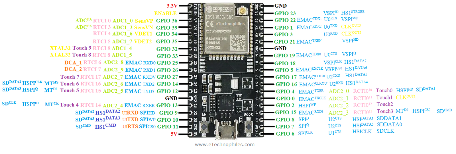
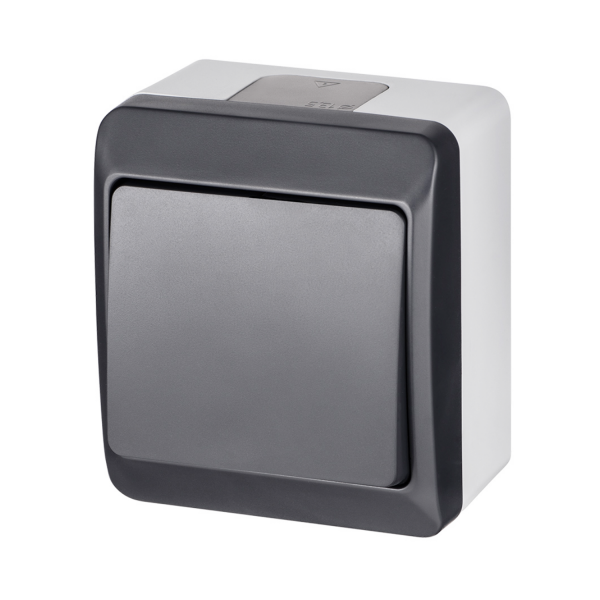 wide shadow
Yeah, I have that. I just couldn't tie that to Arduino programming.