#help-with-arduino
1 messages · Page 2 of 1
 quick maple
yeah I assume you want to know if it works to make sure it's not Dead on Arrival as well?
and when you say doesn't work what exactly do you mean? Do you expect a led to tell you it works ?
 grim bane
I expect the i2c scanner sketch to pick it up
quick maple
or did you do a sketch to scan for i2c adress?
grim bane
I am getting voltage through the SDA and SCL pins, I have two of the same sensor and both are not working.
 tardy iron
did you pull up the CSB pin as suggested earlier? 1k resistor to VCC might be safe/good enough?
grim bane
@tardy iron I did with the 10k-47k tries. Just tied 1k and 510 resistors with no luck either
I just directly connect the CSB pin to the power line right?
bois and girls I think we did it
I think I had to "reset" the chip by disconnecting the power to it and not just hitting the reset button on the arduino
it is switch addresses its finding each time tho... ?
 tardy iron
oh yeah, it might latch its bus mode on power-up there are address selection pins (CAD0 and CAD1, though your board has CADY?) that you might have to wire to GND or VCC to keep a stable address, or maybe it's a weird part that has multiple addresses?
basically if there aren't pullups or pulldowns internally on those address lines, it might read noise from them and keep changing its apparent address
grim bane
I put all other pins onto ground and it seems to be sitting on 0x0C stable
thank y'all ❤️
 snow quest
i'm trying to attach and detach an interrupt within my main program, and getting unexpected results. is this not possible?
i.e. in the loop() function rather than setup()
there should be no difference right?
 sturdy plover
That file does not exist
 gilded swift
sturdy plover
That file does not exist
gilded swift
sturdy plover
That file does not exist
Okay, you should be able to add the library through the library manager. Once you do that, try building it
 native dagger
Never got an answer to this, but I'll ask in another way. Does anyone else experience this? The arduino IDE constantly forgets boards that I have loaded into it on restart. Not just reverting to the UNO, that's fine I can always switch back. Instead it actually forgets that I have installed for example adafruit SAMD boards, and I have to re-do it every time. Anyone else?
 pine bramble
Nope. That's bizarre.
The packages directory and staging directory hold all the files.
staging holds the .zip files.
Need to do a careful study of where these files are kept. I'd never noticed it keeps a copy of every .zip .. in an entirely separate subtree from the active unzipped libraries.
quick maple
native dagger
Never got an answer to this, but I'll ask in another way. Does anyone else exper...
For the record, You did get an answer but for some reason decided that mine was bad or something and stopped replying to any questions I had like if it worked fine if you ran it as admin or if you got it from the windows store or arduino site and if there were logs from defender/etc indicating blocked. So I assumed it worked or you had found what was blocking it or something so I didn't insist
native dagger
I must have gotten distracted
pine bramble
Recently rebuilt IDE subsystem on Linux:
https://termbin.com/35wy
quick maple
he is on windows
 vale leaf
Where is the documentation about BMP3xx sampling settings
vale leaf
Anywhere where it explains what the differences between these are?
 leaden walrus
difference between what? like data rate vs. oversampling? or what each one's options are?
vale leaf
what each option of oversampling does
leaden walrus
checkout the datasheet for those details
 analog lagoon
I'm learning I2C for the first time for a project using PCA9685 16-channel servo drivers (except I'm using them for driving RGB LEDs.) I've gotten the drivers to successfully activate the LEDs, but when I try to turn them off the LEDs are just very very dim. I'm using this function: pwm1.setPWM (0, 4095, 0); On the adafruit site FAQ for this product it says to use 4096 rather than 4095 to turn it off completely; when I tried that it turned them on to full brightness. Any idea what might help with this?
analog lagoon
I'm not sure if it's an error on the adafruit site, or something I'm doing wrong, but when I change the function to pwm1.setPWM (0, 0, 4096); that actually turns it all the way off. On the adafruit site it says to use pwm1.setPWM (0, 4096, 0); Being lost in noobtown is rough sometimes, but through accidental trial and error I have figured out a working solution.
leaden walrus
it shows both full on and off?
https://learn.adafruit.com/16-channel-pwm-servo-driver/library-reference#using-as-gpio-2980401
analog lagoon
Yeah you're right... didn't see that. I was referencing the FAQ where it has it flipped around: https://learn.adafruit.com/16-channel-pwm-servo-driver/faq

Adafruit Learning System
Learn how to connect and program the 16-channel 12-bit PWM/Servo Driver with Arduino, Python or CircuitPython
sturdy plover
How can I get my adafruit bluefruit sense to send battery, temperature, humidity, barometric pressure and illuminance via the bthome (https://bthome.io/) standard? Whould it be comparable to this (https://learn.adafruit.com/adafruit-feather-sense/advertising-beacon) example?

BTHome
Free and open standard for broadcasting sensor data over Bluetooth LE.

 deft depot
not much going on the website. research the open home I guess. Or home assistant. Or something from Adafruit's tutorial lol. how did you hear of bthome?
 north stream
sturdy plover
How can I get my adafruit bluefruit sense to send battery, temperature, humidity...
north stream
sturdy plover
How can I get my adafruit bluefruit sense to send battery, temperature, humidity...
It looks like it wraps up the sensor data in a structure and sends the result with the BTHome protocol in this module: https://github.com/rbaron/b-parasite/blob/main/code/b-parasite/src/prst/ble.c

GitHub
🌱💧 A Bluetooth Low Energy (BLE) soil moisture sensor. - b-parasite/ble.c at main · rbaron/b-parasite
sturdy plover
deft depot
not much going on the website. research the open home I guess. Or home assistant...
I heard about it on a livestream with one of the head developers for home assistant. I want to have an esp32 to work as a wifi bridge through esphome that can read the sensor data from my Bluefruit sense.
native dagger
Would anyone be willing to pull request the pins required for the RP2040 board for this library in the #if defined section? I am working on making sure I have the right pins
Nevermind! The pins are already correct
I came across someone using the DS3231 RTC and the VS1053 together and having severe issues, but unfortunately the post never came to a conclusion and is 5 years old. They weren't using adafruit libs however. Can anyone think of a reason why adafruit I2C RTC library might interfere with an adafruit SPI MP3 player library?
 cedar mountain
native dagger
I came across someone using the DS3231 RTC and the VS1053 together and having se...
cedar mountain
native dagger
I came across someone using the DS3231 RTC and the VS1053 together and having se...
Not offhand. They ought to be pretty independent, but it's also not the sort of conflict that anyone would be specifically testing for.
native dagger
yeah that's fair
I think I'm going to just use the internal RTC
bypass the issue. The internal is good enough for my purposes
 sage lichen
Hi, would somebody be able to help me with reading from an i2c sensor?
It doesn't have a library so I am trying to implement it myself using the wire library
quick maple
which sensor ?
sage lichen
I3G4250D
This is the datasheet I am using as reference: https://www.st.com/content/ccc/resource/technical/document/datasheet/e4/b1/d1/62/1a/e6/44/2f/DM00168691.pdf/files/DM00168691.pdf/jcr:content/translations/en.DM00168691.pdf
Whenever I read from the OUT_X_L and OUT_X_H registers, I am just getting 11111111
quick maple
are you interfacing directly with it or you use an intermediadry like a breakout, or i2c expander or i2c backpack ?
sage lichen
Interfacing directly with it
quick maple
and did you use the 10k pullups on sda/scl ?
sage lichen
Yeah
And another I2C device on the same bus is working correctly
This is the pcb its all on haha
quick maple
doesn't work with this: https://github.com/RAKWireless/RAK12025-I3G4250D ?

GitHub
Library for the RAK12025 Gyroscope Module. Contribute to RAKWireless/RAK12025-I3G4250D development by creating an account on GitHub.
tardy iron
are you checking for errors from the Wire methods? consistently reading all-ones sounds suspiciously like a non-responsive device on I2C, so you might be getting undetected NAKs if you're not checking for errors
sage lichen
quick maple
doesn't work with this: https://github.com/RAKWireless/RAK12025-I3G4250D ?
Yeah I saw that but it seems to be for a specific breakout board
sage lichen
tardy iron
are you checking for errors from the `Wire` methods? consistently reading all-on...
Oh do the methods return 1 if there is an error?
quick maple
sure but the way it read the values etc could be used as an inspiration
tardy iron
sage lichen
Oh do the methods return 1 if there is an error?
can you show your code, please?
quick maple
the rest is just a couple more capacitors/sensors
sage lichen
tardy iron
can you show your code, please?
Yeah
byte x0, x1;

void loop() {
  Wire.beginTransmission(0x68);
  byte error = Wire.endTransmission();
  if(error != 0) {
    Serial.println("Gyroscope Disconnected :(");
    Serial.println("===================================");
  }

  Wire.requestFrom(0x28, 2);
  if(Wire.available() <= 2) {
    x0 = Wire.read();
    x1 = Wire.read();
  }

  Serial.print("X0: ");
  Serial.println(x0);
  Serial.print("X1: ");
  Serial.println(x1);

  idleLed();

  delay(10);
}
are you talking to two different devices? one at 0x68 and one at 0x28? or are you trying to access a register that's at internal address 0x28 on the device?
sage lichen
The register is at 0x28 on the device
And I was requesting 2 bytes from it because I thought that the register address was the start address and I needed to read the value from that register and the next register
 tardy iron
sage lichen
The register is at 0x28 on the device
tardy iron
sage lichen
The register is at 0x28 on the device
yeah, then you need to use the same address 0x68 for the requestFrom, but you typically need to first send the byte 0x28 to address 0x68 to tell it that's where you want to read from. (and there's additional complication if it requires a "repeated START", but not all devices require it)
sage lichen
Oh
Wait the repeated start thing seems familiar
I think it was in the datasheet
One sec

And then this was the table
 tardy iron
oh, it's got a weird thing going where you set the high bit of the register number to request auto-increment mode
sage lichen
What does that mean 😅
tardy iron
roughly, it means you bitwise-or 0x80 with the desired register address if you want to turn on auto-increment to read or write multiple consecutive registers in a single transaction
you don't need to worry about "SAD+R/W" stuff; that's taken care of by Wire
sage lichen
Ohhhh ok cool that makes sense
So that was what I was thinking it would already let me do by default
So how do I turn on auto-increment specifically? @tardy iron
tardy iron
yeah, so i think 0xA8 instead of 0x28 as the register address to turn on auto-increment
sage lichen
Ah ok
tardy iron
and to get a repeated START condition, specify the optional argument stop like false like Wire.endTransmission(false) when you're sending the register address
sage lichen
Ah ok I see
byte x0, x1;

void loop() {
  byte error;
  Wire.beginTransmission(0x68);
  error = Wire.endTransmission();
  if(error != 0) {
    Serial.println("Gyroscope Disconnected :(");
    Serial.println("===================================");
  }
  Wire.beginTransmission(0x68);
  Wire.write(0x28);
  Wire.requestFrom(0xA8, 2);
  Wire.endTransmission(false);

  // step 5: receive reading from sensor
  if(Wire.available() <= 2) {
    x0 = Wire.read();
    x1 = Wire.read();
  }


  Serial.print("X0: ");
  Serial.println(x0);
  Serial.print("X1: ");
  Serial.println(x1);

  idleLed();

  delay(10);
}
So this would be the new program?
tardy iron
sage lichen
So this would be the new program?
not quite… more like
  Wire.beginTransmission(0x68);
  Wire.write(0xA8);
  error = Wire.endTransmission(false);
  // add error checking here
  error = Wire.requestFrom(0x68, 2);
  // add error checking here
i think. i haven't tested or compiled it
 tardy iron
you might need to do some setup of sampling frequency first
sage lichen
Wait is this important?
 tardy iron
sage lichen
Wait is this important?
tardy iron
sage lichen
Wait is this important?
that's what i was referring to when i said you should bitwise-or 0x80 with the desired register address if you wanted to turn on auto-increment
sage lichen
Ohhhh I misunderstood the first time and thought you meant with the device address
Ok that makes more sense
quick maple
I guess someday I can write a library too, this datasheet seems complicated 😦
sage lichen
quick maple
I guess someday I can write a library too, this datasheet seems complicated 😦
Ikr
Once I get it figured out I might
@tardy iron This seems to be the issue: error = Wire.requestFrom(0x68, 2);
(I added some error handling)
tardy iron
sage lichen
<@824013908490059826> This seems to be the issue: ```error = Wire.requestFrom(0x...
what value is error?
sage lichen
One sec
tardy iron
sage lichen
<@824013908490059826> This seems to be the issue: ```error = Wire.requestFrom(0x...
oh wait, sorry, maybe that gives the length actually read
sage lichen
Ah yeah
quick maple
I feel like I made a mistake getting a pricey 4-in-1 sensor 😦
sage lichen

And the value is "2" which is correct
So I guess its not giving an error after all
tardy iron
yeah, sorry, i was misremembering how that method behaved. i think in practice most people ignore the return value and use available() instead
sage lichen
All good
Strangely, it gives different values after each restart
But the values stay the same
So there must be something I have to do to tell it that I've read the values or something
tardy iron
yeah, you probably need to read the datasheet in more detail about how to configure it. some sensors need to be commanded to take a new sample, and others have a mode where they keep taking samples at a regular rate, etc.
 quick maple
there is a stream mode apparently too, I have to ask but I suppose you used the resistors/capacitors they said to use for the the filter ?
 tardy iron
you might want to look at Arduino libraries for related devices from ST; their command structures tend to be similar
quick maple
yeah even if it's not 100% correct it might give you an idea of the right sequence to arm it/read from it
sage lichen
Yeah
quick maple
that breakout doesn't seem very complicated or I'm blind
probably just provide the filter they asks about
sage lichen
Yeah honestly thats probably it
Giving it a shot now
Oh it actually works 💀
Woah this thing is precise
So much better than the mpu3060 or whatever
sage lichen
Its expensive if you're going to make more than 1 unit
They cost like $10 each
So more than pretty much everything else combined on my pcb 🤣
But now I see why. This thing is awesome
quick maple
Well the base of the robot was 150$
and cameras are likely to be 175$ each + 300$ for FLIR, so yeah cost around 10$ not going to faze me
sage lichen
Oh wow yeah you'll be good then 🤣
Meanwhile I'm over here hoping to sell these for $50/each eventually
That $10 part is pretty expensive then 🤣
quick maple
probably even going to have two to do sensor fusion/sampling (these might do that already internally)
sage lichen
Oh yeah thats the plan
I forgot to put a magnetometer on this version of the board but this gyro is accurate enough that I'm not too nervous
quick maple
that robot is a life project though, hopefully I finish it. By the time I'm done hopefully thermal cameras available for DIY will be much less
sage lichen
But yeah going to have to fuse it with the accelerometer
sage lichen
quick maple
that robot is a life project though, hopefully I finish it. By the time I'm done...
Oh yeah
quick maple
and we're going to have a battery technology that provide as much density as gasoline like they keep promising us...
quick maple
nah they say nanowire might approach gasoline and that air-metal battery might be 5x better
sage lichen
Oh wow
quick maple
can't wait to see it. Meanwhile walmart sells r/c toys with 1810 zinc-carbon batteries 😦
sage lichen
🤣
quick maple
I'm sure if it was less expensive they'd use the 2nd oldest type of battery, lemon juice in a jar off metal
sage lichen
Oh yeah
quick maple
make me facepalm every time I see "heavy duty" on them... kinda like seeing Turbo GTR on a 40hp car.... but I disgress
sage lichen
I mean you could put a turbo on a 40hp engine
quick maple
Yeah it's that and putting Gran Turismo which is a competition to last 24h in a race and go really fast on a car with a lawmmower enginew
even if you put turbo on it and NOS you'll get at most 80hp
sage lichen
🤣
quick maple
meanwhile a "shareware"/cut-down version of a V8 will probably give you 280hp..
quick maple
What is your take on this: I feel like a I made a mistake getting a Pimironi PIM357- BME680 Breakout - Air Quality, Temperature, Pressure, Humidity Sensor. Like I was checking for a sensirion temp/humidity sensor and saw those Bosch 4-in-1
but since sensirion are 20$ and BME is 29$ I guess the accuracy is going to be really bad
cedar mountain
quick maple
What is your take on this: I feel like a I made a mistake getting a Pimironi PIM...
You shouldn't take the price of a breakout board as a proxy for the quality of the sensor... there are a lot of other factors that go into that. But the Bosch sensors are generally well-regarded, so you should check the datasheets to compare specs before getting too worried.
 sand steppe
Hi All,
I am using Adafruit Grand Central M4, I have added OTA support for the same over Ethernet. If there is a power failure during this re-write, the operation is interrupted and does not complete. The application region does not have the complete code re-written and the system breaks. When I power ON the board again, it is unable to execute the new firmware and cannot rollback on to the old firmware either. Can anyone help me to built a bootloader which has a rollback feature, when the system breaks.
cedar mountain
sand steppe
Hi All,
I am using Adafruit Grand Central M4, I have added OTA support for the s...
A common technique to mitigate this is to have a checksum for the firmware, so the bootloader will be able to detect a corrupt image and choose not to run it.
sage lichen
Let me know if this is the wrong channel, but in general, should I run a calibration script for my gyro each time on boot, or just do 1, more comprehensive, calibration and hard-code the offsets for future use?
native dagger
Adafruit libs are cpp/h files, so it should be possible for me to modify one and then make it into a library for arduino right?
Specifically I'm looking to add to the VS1053 library and add reading decode time into the mix
It sure seems like it's really simple, just reading from the decode time register
 eternal cloud
native dagger
Specifically I'm looking to add to the VS1053 library and add reading decode tim...
eternal cloud
native dagger
Specifically I'm looking to add to the VS1053 library and add reading decode tim...
Do you mean this one https://github.com/adafruit/Adafruit_VS1053_Library ? This is already an Arduino library, you should be able to add functionality to it and use it no problem
native dagger
Yeah that's the one, I just wasn't sure how to get it on the arduino
That said it turns out the functionality on the chip is really minimal and not sufficient for my needs
eternal cloud
native dagger
Yeah that's the one, I just wasn't sure how to get it on the arduino
The Adafruit libraries are already available for download in the Arduino IDE, or you can add your own with modifications https://docs.arduino.cc/software/ide-v1/tutorials/installing-libraries
native dagger
Ah I wasn't sure if they were editable. I haven't done arduino in a while
sand steppe
cedar mountain
A common technique to mitigate this is to have a checksum for the firmware, so t...
Thank you for your reply. Is there are any examples or getting started documents for the same to add CRC or checksum for validation of firmware.
north stream
sand steppe
Thank you for your reply. Is there are any examples or getting started document...
A very simple checksum algorithm is to add up all the bytes and just keep track of the least significant byte of the result. Then store the result somewhere. To check it, add up all the bytes and see if the last (or only) byte of the result matches. Many implementations complement the result or start with some value other than zero, but the basic notion is the same. You could also use XOR instead of add. For more reliability, you could use a CRC8 calculation instead of just adding or xoring the bytes.
sage lichen
Hey guys, for some reason my ESP12f is crashing when I run WiFi.begin()
Any ideas as to what could cause this?
sage lichen
Nvm, looks like it was due to not enough power
 ember geyser
Hello! looking for help changing the brightness on my POV led staff. shurik179 build. Istybitsy m4. unfamiliar with code, Is there any way to easily turn down the brightness to conserve battery life? we put 9000mah batteries in this thing but it still eats it up fast and honestly its too bright you cant even look at the thing
quick maple
my apologies, maybe I'm missing something, but don't they have to be very bright for the effect to work ?
ember geyser
no, I don't believe so
 inland gorge
ember geyser
Hello! looking for help changing the brightness on my POV led staff. shurik179 b...
inland gorge
ember geyser
Hello! looking for help changing the brightness on my POV led staff. shurik179 b...
Do you have a link to the code? Most Arduino-based LED projects have a brightness setting, but it depends on the library used
Is your POV staff this code? https://github.com/shurik179/povstaff/blob/main/code/povstaff/povstaff.ino
If so, then since it's using FastLED, you should be able to add to line 80 (after FastLED.addLeds()):
FastLED.setBrightness(128); // 0-255, 128 = "half"
Looking for help: I'm using a few PCA9865s to drive a bunch of RGB LEDs. When I disconnect the external power supply, and just have the arduino plugged in (to my computer for example, while updating code), the LEDs still activate. My worry is this will fry my arduino (I'm using 20 RGB LEDs, so essentially 60 LEDs.) Am I wrong here? Should this be happening?
leaden walrus
how are the LEDs being powered?
eternal cloud
analog lagoon
Looking for help: I'm using a few PCA9865s to drive a bunch of RGB LEDs. When I...
When the arduino board is powered (from the USB) , the whole circuit is powered, so yes, the LEDs should light up.
And yes, if you have a lot of LEDs and draw a lot of current at once, you could fry something  (depending on the protection circuits that are on the boards...)
I think the external power supply is better kept connected, just in case
analog lagoon
Thanks so much… I read somewhere it might not be safe to have both an external supply and usb plugged into the arduino at once. Is that true? The external supply powers the arduino as well when it’s not plugged in via USB. Eventually it will be a standalone thing so I want the arduino and LEDs to be on the same external supply. It’s a 2amp 5v barrel jack.
quick maple
It's hard to imagine that much leds with a servo board not using like 6A
and the board specifically say to not power the servos from the arduino
(or anything that take a couple of amps like so much leds etc)
eternal cloud
analog lagoon
Thanks so much… I read somewhere it might not be safe to have both an external s...
I'm pretty sure the safety warning was about the voltage of the power supply, you don't want to have different voltages in your circuit
Since your external power supply is 5V , just like the USB , it's okay
analog lagoon
Total beginner here: I was thinking each pin has a 220ohm resistor on it, and green/blue are max 3.2v. So each pulls less than 20mA. So 20mA x 60leds = 1.2amps. Is this wrong? Closer to 6A?
eternal cloud
Current draw for LEDs is not constant, depends on the brightness, and the length of time they are on.
2A should probably be enough, but if you want to light them all at the same time on full brightness, or if you notice that some of them are dimmer , you can always get a higher current power supply.
PWM and lower brightness are your friends though 😆
analog lagoon
Yeah I was planning on mapping max brightness to much lower, since 60leds are extremely bright.
ember geyser
inland gorge
Do you have a link to the code? Most Arduino-based LED projects have a brightnes...
Thank you, sorry just getting back to this
sage lichen
I have a question about some code that I found
#include <Wire.h>
#include <math.h>

#include <FRAM_MB85RC_I2C.h>


//define a struct of various data types
typedef struct MYDATA_t {
    bool data_0;
    float data_1;
    long data_2;
    int data_3;
    byte data_4;
};

//define a struct joining MYDATA_t to an array of bytes to be stored
typedef union MYDATA4I2C_t {
 MYDATA_t datastruct;
 uint8_t I2CPacket[sizeof(MYDATA_t)];
};

MYDATA4I2C_t mydata; //data to be written in memory
MYDATA4I2C_t readdata; //data read from memory

//random address to write from
uint16_t writeaddress = 0x025;

//Creating object for FRAM chip
FRAM_MB85RC_I2C mymemory;

void setup() {

    Serial.begin(9600);
    while (!Serial) ; //wait until Serial ready
    Wire.begin();

    byte arraySize = sizeof(MYDATA_t);

    Serial.println("Starting...");

    mymemory.begin();


//---------init data - load array
    mydata.datastruct.data_0 = true;
    if (mydata.datastruct.data_0) Serial.println("true");
    if (!mydata.datastruct.data_0) Serial.println("false");
    mydata.datastruct.data_1 = 1.3575;
    mydata.datastruct.data_2 = 314159L;
    mydata.datastruct.data_3 = 142;
    mydata.datastruct.data_4 = 0x50;


//----------write to FRAM chip
    byte result = mymemory.writeArray(writeaddress, arraySize, mydata.I2CPacket);

    if (result == 0) Serial.println("Write Done - array loaded in FRAM chip");
    if (result != 0) Serial.println("Write failed");
    Serial.println("...... ...... ......");
}
This program stores an object created from a struct to FRAM storage
But I don't understand where I2CPacket is given a value
Because it seems that that is what is actually storing the bytes of data to be written, but I don't understand how it is given a value
north stream
sage lichen
But I don't understand where I2CPacket is given a value
That's what the union does: it tells the compiler "these things share the same chunk of memory", so writing to datastruct and I2CPacket are overlaid. Some code does this with pointer punning, this code does the same thing with the union.
 crimson lark
Hey guys
I need some help
I'm just trying to make a circuit to control a servo using a flex sensor
So if someone can help me, that'd be great
Pls ping me if you can
Thanks in advance
<@&617066238840930324>
cedar mountain
crimson lark
So if someone can help me, that'd be great
The rule of thumb is just to go ahead and provide enough specifics for someone to be able to usefully answer a question for you and get you past where you're stuck. It's rare for someone to volunteer as a tutor and hand-hold you through the whole process, but many folks will be able to understand where you are and help you fix a bug or point you in the right direction for the next step.
crimson lark
I would also prefer to vc
crimson lark
cedar mountain
The rule of thumb is just to go ahead and provide enough specifics for someone t...
Oh, I mightve not explained this
But I made the circuit
Just need someone to help me check it
And I also have many questions
So I feel like vcing would be the most efficient wau
Way
cedar mountain
For a circuit review, #help-with-hw-design is probably the best place, if you can post your schematic and maybe point out areas where you are uncertain.
crimson lark
Okay thank you
sage lichen
Hey guys, I am facing an issue that has me stumped
I am programming an ESP-12f to read everything stored in FRAM storage into an array of objects instantiated from a struct
But for some reason, I am getting a software wdr crash after the setup function now
void setup() {
  // put your setup code here, to run once:
  Serial.begin(115200);
  Wire.begin();
  delay(5000);

  i2cScan();

  sensorManager.begin();
  storageManager.begin();
  //storageManager.clearFlightData();

  const int dataSize = 250; //285
  AlphaStorageManager::DATA_t flightData[dataSize];
  storageManager.getFlightData(flightData, dataSize);

  for(int i = 0; i < dataSize; i ++) {
    Serial.print("Datapoint: ");
    Serial.println(i);
    Serial.print(flightData[i].g);
    Serial.print(",");
    Serial.print(flightData[i].a);
    Serial.print(",");
    Serial.print(flightData[i].alt);
    Serial.print(",");
    Serial.println(flightData[i].timestamp);
  }

  strip.begin();           // INITIALIZE NeoPixel strip object (REQUIRED)
  strip.clear();
  strip.show();            // Turn OFF all pixels ASAP
  strip.setBrightness(255);

  delay(500);
}
The crash is after the setup function but before the loop function
So I am super confused as to what could be the cause
Actually, it appears to be crashing inside of the loop function...
But inside of the loop function everything is commented out except for a function that has been working in the past and just interacts with a neopixel
tardy iron
memory corruption bugs can cause nonlocal effects that are difficult to diagnose
tardy iron
overrunning an allocated array or structure is one thing that can cause a delayed crash in a future allocation. i guess exhausting heap memory is another
sage lichen
Yeah I think I was exhausting the heap memory
Because when I decreased the size to 50 it worked
Guess I should've known that I cant load 8kb into heap memory lol
tardy iron
depends on the device, i guess, and what else is in RAM
sage lichen
tardy iron
depends on the device, i guess, and what else is in RAM
How would I store an array in ram? Never done it before
Actually never mind, I think I'll just paginate the data
So it only has to store 1/5 in memory at once
tardy iron
sage lichen
How would I store an array in ram? Never done it before
what do you mean? usually in C, all arrays are in RAM, unless they're tiny enough to be optimized into registers, or you're explicitly storing them somewhere else like flash or EEPROM
sage lichen
Ah never mind
So I was storing it in ram then
And I guess heap memory is a subset of ram?
tardy iron
yeah
cedar mountain
sage lichen
And I guess heap memory is a subset of ram?
In this case, since you declared the array as a local variable of setup(), it would have been allocated on the stack. Heap memory gets used with new or malloc().
sage lichen
cedar mountain
In this case, since you declared the array as a local variable of `setup()`, it ...
Is there more heap memory than stack?
tardy iron
ah, i missed that part
tardy iron
sage lichen
Is there more heap memory than stack?
on most architectures, they're allocated from the same RAM, but at opposite ends, and they grow toward each other. don't let them collide
cedar mountain
I'm not sure how the Arduino ESP framework works. If it's got FreeRTOS running underneath it, there may be separate (more limited) stacks associated with each task.
sage lichen
I ended up going with pagination
And just looping over pages of the data which can all fit within the memory limitations
Just needs to be able to spit it all out over serial so it'll work
Thanks for the help though @tardy iron @cedar mountain . Definitely wouldn't have figured out that it was a memory issue lol
 neat shoal
hello 👋
excuse me i have problem with blynk app .. previously i was using the old version of blynk with esp-01 but now when i changed to blynk 2.0 it doesn't work properl ..
my circuit to display temp and humidity on blynk and controls the relay with one click bottom .. the sensor working and have data on blynk the problem only with bottom doesn't work
neat shoal
neat shoal
hello 👋
excuse me i have problem with blynk app .. previously i was using the ...
#define BLYNK_PRINT Serial // Comment this out to disable prints and save space
#include <ESP8266WiFi.h>
#include <BlynkSimpleEsp8266.h>
#include <DHT.h>
char auth[] =
char ssid[] =
char pass[] =
#define DHTPIN 2
#define DHTTYPE DHT11
DHT dht(DHTPIN, DHTTYPE);
SimpleTimer timer;
void sendSensor()
{
float h = dht.readHumidity();
float t = dht.readTemperature(); // or dht.readTemperature(true) for Fahrenheit
if (isnan(h) || isnan(t)) {
Serial.println("Failed to read from DHT sensor!");
return;
}
// You can send any value at any time.
// Please don't send more that 10 values per second.
Blynk.virtualWrite(V5, h);
Blynk.virtualWrite(V6, t);
Serial.print("Temp = ");
Serial.print(t);
Serial.print(" Humi = ");
Serial.println(h);
}
void setup()
{
//pinMode(3, OUTPUT);
Serial.begin(9600); // See the connection status in Serial Monitor
Blynk.begin(auth, ssid, pass, "blynk.cloud",80);
dht.begin();
// Setup a function to be called every second
timer.setInterval(1000L, sendSensor);
}
void loop() {
Blynk.run(); // Initiates Blynk
timer.run(); // Initiates SimpleTimer
}
BLYNK_WRITE(V4)
{
// button was pressed
if (param.asInt() == 1)
{
digitalWrite(3, HIGH);
timer.setTimeout(60000L, relayOff);
}
}
void relayOff()
{
digitalWrite(3, LOW);
}
deft depot
is there an error message?
if they can't answer here maybe you could ask:
https://community.blynk.cc
maybe the new lib has a bug?
You said you did not change your code at all?

Blynk Community
Friendly community of developers who build projects with Blynk. Ask questions and share your ideas.
 terse lava
Hey all! Long time no issues 🙂
A more general question;
I'm using the VEML7700 to capture lux values and the VL53L4CX for distance. The VL53L4CX polls distance values very fast but the lux values take an integration time to capture (between 25ms all the way up to 800ms). Is there such a thing as continuing to run the rest of the loop while the VEML is still polling?
I ask because I'm trying to capture light with a diffuser over the sensor, so the integration time tends to lean on the higher end while using the AUTO method
sage lichen
terse lava
Hey all! Long time no issues 🙂
A more general question;
I'm using the VEML7700 ...
I would suggest implementing a state machine
So you can switch to one state while the sensor is polling, as well as store the time that integration began
And after each loop, if the state is set to "polling", check how long it has been since integration began
If the time is greater than the integration time, then you can switch into another state where you would complete the post-integration tasks and then go back into the original state to start over again
terse lava
ah, that would be very useful!
sage lichen
Yup!
terse lava
thank you! apologies for not being familiar with the term
sage lichen
No problem haha, don't worry abt it
 tame sun
Hello, I am working on a project with the adafruit i2c rotary encoders and the 1x4 neokey. I have them both connected to my feather rp2040's stemma qt port(I2C1). I have just switched from circuit python to ardunio code and my question is: the example code I am trying to use for both these devices seems to be using the I2C0 bus on the feather. I can't seem to find a obviously to change what bus is being used. Is this possible? Thanks.
 livid osprey
tame sun
Hello, I am working on a project with the adafruit i2c rotary encoders and the 1...
livid osprey
tame sun
Hello, I am working on a project with the adafruit i2c rotary encoders and the 1...
In Arduino, you would declare Wire1.begin() in place of Wire.begin()?
tame sun
livid osprey
In Arduino, you would declare Wire1.begin() in place of Wire.begin()?
I think I got it working for the encoder using:
Adafruit_seesaw ss = Adafruit_seesaw(&Wire1); seesaw_NeoPixel sspixel = seesaw_NeoPixel(1, SS_NEOPIX, NEO_GRB + NEO_KHZ800,&Wire1);
tame sun
livid osprey
In Arduino, you would declare Wire1.begin() in place of Wire.begin()?
Not sure about the neokey this does not seem to work: Adafruit_NeoKey_1x4 neokey = Adafruit_NeoKey_1x4(&Wire1);
tame sun
livid osprey
In Arduino, you would declare Wire1.begin() in place of Wire.begin()?
How would you use Wire.begin()?
livid osprey
tame sun
How would you use `Wire.begin()`?
After including <Wire.h>, you would call Wire1.begin() in your void setup() section.
Or Wire.begin(), depending on which bus you’re trying to initialize.
It’s similar to how one would initialize a Serial port with Serial.begin(baudrate), but without any baudrate argument.
https://learn.adafruit.com/scanning-i2c-addresses/arduino has an example in the bus scanner code, you can use this (or any other existing I2C code) as a reference and copy the relevant sections as needed.

Adafruit Learning System
Hello? Are you there? Scan and find out.
tame sun
livid osprey
After including <Wire.h>, you would call Wire1.begin() in your void setup() sect...
Will give this a go, thanks
Still not working with the neokey. Adding WIRE.begin() had no effect. Here is the full code
livid osprey
tame sun
Still not working with the neokey. Adding WIRE.begin() had no effect. Here is th...
Have you tried running the scanner sketch to verify your connection on the I2C bus?
tame sun
livid osprey
Have you tried running the scanner sketch to verify your connection on the I2C b...
I have
tame sun
livid osprey
Have you tried running the scanner sketch to verify your connection on the I2C b...
I2C Scanner
Scanning...
I2C device found at address 0x30 !
I2C device found at address 0x31 !
I2C device found at address 0x36 !
I2C device found at address 0x37 !
I2C device found at address 0x38 !
I2C device found at address 0x3A !
I2C device found at address 0x3C !
I2C device found at address 0x3D !
done
On the I2C1 bus(Wire1)
livid osprey
@tame sun Ah, the &Wire reference is inside the Neokey constructor. Try replacing “Adafruit_NeoKey_1x4 neokey;” with “Adafruit_NeoKey_1x4 neokey(0x30, &Wire1);” and see if that works.
tame sun
livid osprey
<@441445435572355083> Ah, the &Wire reference is inside the Neokey constructor. ...
Great, that works. Thanks very much for your help
sage lichen
I don't know if this is the right place to ask or not, but I've run into a programming issue that I just for the life of me cannot solve
I am outputting a bunch of data over serial from my microcontroller, and I created a website that uses the web serial api and is supposed to read the data coming in over serial
It works sometimes, but other times it throws an error saying "A buffer overrun has been detected."
It should only be like 4kb of data, so I'm a bit confused as to how this could be happening on my computer
cedar mountain
sage lichen
It should only be like 4kb of data, so I'm a bit confused as to how this could b...
It looks like the web serial port defaults to a 256-byte buffer size. You can add a parameter to the port open() call to change that to something larger, though.
sage lichen
Thanks!
sage lichen
cedar mountain
It looks like the web serial port defaults to a 256-byte buffer size. You can ad...
So I changed it to 1mb, and it worked for a few refreshes but now it is back to throwing the same buffer overrun error. Is there a way to purge / clear the buffer?
cedar mountain
sage lichen
So I changed it to 1mb, and it worked for a few refreshes but now it is back to ...
Hmmm, I wonder if there's something happening more at the OS level, then... it's weird that a 1M buffer would be overrun by 4k of data.
tardy iron
is your device streaming data over serial continuously, or only sending when requested?
sage lichen
Only when requested
I send a command "!flightData" and then it replies with the data and terminates with "!end"
And the strange thing is it works for a few times (with me refreshing the site between each attempt), but then after a few times it throws the error and doesn't work anymore
Even stranger, when I change the buffer size it works again for a few times before breaking once again...
Even if I decrease the buffer size
north stream
Sounds like the buffer is not being released when the data is read
 rich coral
anyone managed to get RP2040 Connect OTA working?
 merry cargo
So, I've got a Feather 328P, and I'm looking for the Arduino equivalent of CircuitPython's touchio. Does that exist, or should I just give up and learn CircuitPython? 😃
 solemn cliff
merry cargo
So, I've got a Feather 328P, and I'm looking for the Arduino equivalent of Circu...
solemn cliff
merry cargo
So, I've got a Feather 328P, and I'm looking for the Arduino equivalent of Circu...
here is a guide for capacitive touch in Arduino on a Flora, which is a 32u4 (which equally doesn't have builtin support for touch, so should work the same on 328 ?)
https://learn.adafruit.com/capacitive-touch-with-conductive-fabric-and-flora
if I understand correctly, to do cap touch you put a large resistor to a pin and gnd, pull up then read and measure how long it takes to go back down, the longer the higher the capacitance, the more likely somebody is touching it
(not that it matters, there's a library for it)
pine bramble
;)
I've used a simple inverter (DIP package) as a kind of theramin input antenna. Floating inputs move around quite a bit if you bring your body close to them, at least sometimes they do.
merry cargo
I ended up using the ADCTouch library. Not very precise, but it'll work for my purposes. https://github.com/martin2250/ADCTouch

GitHub
touch sensing library for Arduino. Contribute to martin2250/ADCTouch development by creating an account on GitHub.
 turbid totem
Can I ask ESP32 questions in here or is there a better room?
tardy iron
are you using Arduino to program it? or you could just ask and we can redirect you if there's a better channel
turbid totem
arudino ide
I can get this ESP32 WROOM to power up via USB or via the 5vdc pin on the board. That said, I cannot get it to connect to wifi if powered via the 5vdc pin. I can only connect to wifi if powered via the usb. I've got 1a going to the pin which should be more than enuf. any ideas?
tardy iron
which board are you using? if it's an Adafruit board, what's the product ID? is your sketch possibly waiting for serial input from USB?
turbid totem
btw, tyvm for using pronouns.
mine are she/her
I think it's an adafruit board but I got it from a friend. It's soldered down now so I cant check. The sketch works if I d/c the 5vdc input and power the board via the usb on a battery.
so not usb input
tardy iron
turbid totem
I think it's an adafruit board but I got it from a friend. It's soldered down n...
like connecting a USB power bank to the USB connector? yeah, that does kind of suggest it's some kind of power issue rather than a USB serial absence issue. i'm not personally familiar with these boards, so hopefully someone more experienced with them can chime in
turbid totem
tyvm
native dagger
turbid totem
btw, tyvm for using pronouns.
If you want, you can have a server specific username that uses your pronouns.
That's how I did it 🙂
livid osprey
turbid totem
I can get this ESP32 WROOM to power up via USB or via the 5vdc pin on the board....
An esp32 WROOM module has no 5v pin for input. Are you using a dev board or a custom pcb?
turbid totem
I'm using a NodeMCU dev board
 cold lagoon
Help i cant burn the bootloader on my ATTINY 44A-SSU. The datasheet says it has a 20Mhz clock speed, which isn't available in the tools menu.

 north stream
I see "External 20 MHz" as an option in the tools menu
cold lagoon
doesn't work either i've tried them all
north stream
What clock are you supplying to the chip?
cold lagoon
does it even have a internal crystal? or do i need a external. i thought i read that it hat an internal clock
cold lagoon
north stream
What clock are you supplying to the chip?
so it needs an external clock?
north stream
It has an internal RC (not crystal) oscillator, I don't know if the blank chips have that enabled or not. If so, you should be able to program them with the speed set correctly (if all the connections are correct). If not, you would have to supply an external signal.
A little web searching indicates the default CKSEL fuse bits are 0010, which should enable the internal 8MHz oscillator, so it should be flashable without supplying an external clock (unless the fuse bits have been changed to something else)
I see you have "Arduino as ISP" selected as the programmer, is that the programmer you're using (i.e. an Arduino running a sketch that allows it to act as an AVR programmer)?
cold lagoon
north stream
I see you have "Arduino as ISP" selected as the programmer, is that the programm...
waaaait a minute
jeah i thought i missed something lol thanks 🙂
 acoustic flume
hi, i have a tft here that claims to have a ili9341 driver, pinout is gnd, vcc, scl, sda, rst, dc, cs. im using the Adafruit_ILI9341 library, and the problem im getting is, it should be 320x240, it does fill noise/snow across all of the screen, but when i try and do a fillScreen on it, the first 80 pixels on the left of every row remains as snow, and a square 240x240, right aligned on the screen shows. anybody any idea why this might be?
inland gorge
acoustic flume
hi, i have a tft here that claims to have a ili9341 driver, pinout is gnd, vcc, ...
what arduino board are you using and what's the wiring between that board and the tft?
acoustic flume
raspberry pi pico, but using arduino framework, and my pins are Adafruit_ILI9341(5, 6, 3, 2, 7) (SPI0 CS, DC, SPI0 TX, SPI0 CLK, RST)
inland gorge
acoustic flume
raspberry pi pico, but using arduino framework, and my pins are Adafruit_ILI9341...
You're using this Arduino core for the Pico? https://github.com/earlephilhower/arduino-pico
acoustic flume
couldnt say, as im using platformio using platform = raspberrypi
board = pico
framework = arduino
inland gorge
without knowing the core, it's hard to say what Arduino pin numbers map to which GPIO pins. It's probably direct, but some cores map Arduino pin numbers to board pin numbers (e.g. on the Pico, GP15 is board pin number 20)
acoustic flume
is there any way of me figuring out which core it is from the core's source? also, ive checked the PinNames and the gpio pins are a direct mapping, p0 == 0
inland gorge
Try these pin choices instead:
const int tft_cs   = 5;  // SPI0 CSn, GP1, GP5, GP17
const int tft_dc   = 4;  // SPI0 MISO, but we're not doing readbacks
const int tft_mosi = 3;  // SPI0 MOSI, must be GP3, GP7, GP19
const int tft_sck  = 6;  // SPI0 SCK, must be GP2, GP6, GP18
const int tft_rst  = 7;  // any pin
Adafruit_ILI9341( tft_cs, tft_dc, tft_mosi, tft_sck, tft_rst);
(I like using named constants for these classes with long argument lists because I get confused args go when)
 inland gorge
I would try Arduino IDE with https://github.com/earlephilhower/arduino-pico core. I have had a bunch of weird issues with platformio
also, did you change your wiring to match?
acoustic flume
i did yes
not a fan of arduino ide. platformio is already installed, was hoping to shortcut having to write a ili9341 library for pico-sdk 😦
odd thing is.. is if i set the rotation, i can move those 80 pixels to the other side of the screen.. :S
inland gorge
I have used that library in Arduino, but I don't think I've used it on RP2040-based boards. It's just doing normal SPI though and I've used many other SPI-based TFTs on Pico. You could also try Arduino_GFX library: https://github.com/moononournation/Arduino_GFX
Do you have a picture or link for the TFT board you're using?
acoustic flume
https://www.aliexpress.com/item/4000830895622.html?spm=a2g0o.order_list.0.0.56b41802bqDq6Y <<< the 2.4" version

aliexpress.com
Smarter Shopping, Better Living! Aliexpress.com
inland gorge
Are you powering it with 5V or 3v3?
acoustic flume
tried with both
inland gorge
Looks like you need to short J1 if you want to power it with 3v3? It's not very clear
acoustic flume
it just works with 3.3 or 5v
inland gorge

that may be only for the touch screen part though
You may have better luck finding a forum for whatever Arduino core your platformio is using
Okay, maybe this works?
#include <SPI.h>
#include <Adafruit_ILI9341.h>
const int tft_cs   = 5;  // SPI0 CSn, GP1, GP5, GP17
const int tft_dc   = 4;  // SPI0 MISO, but we're not doing readbacks
const int tft_mosi = 3;  // SPI0 MOSI, must be GP3, GP7, GP19
const int tft_sck  = 6;  // SPI0 SCK, must be GP2, GP6, GP18
const int tft_rst  = 7;  // any pin

Adafruit_ILI9341 tft = Adafruit_ILI9341(tft_cs, tft_dc); // uses "SPI" by default

void setup() {
  SPI.setSCK(tft_sck); // "SPI" is SPI0, "SPI1" is SPI1
  SPI.setTX(tft_mosi);
  tft.begin();
}
this is assuming the Arduino core you're using is the earlephilhower one
 lyric pivot
Anyone else tried the VEML7700 lib
I cannot get it working at all

Returns a gain of 1 regardless of what I set it to, returns an integration of 100ms regardless of what I set it to, returns fixed 0 for every value regardless of how much light I shine on it
possible my ESP32 BSP is out of date as I look at closed github issues, checking
Fixed, ignore me then, away I disappear
I did indeed have to bump the BSP
 charred tree
Has anyone tried the #4026 Adafruit Soil i2C Sensor soilsensor_example file in the seesaw library? I can't get it to work with my QT PY ESP32 S2. I'm using the Qwiic/stemma connector which on the QT board requres an extra line in setup Wire1.setPins(SDA1, SCL1);
sage lichen
Sorry if this is the wrong channel, but what would be the best way for me to make a simple desktop app?
I know pretty much every major programming language so that isn't a problem, and this app doesn't have to be pretty either
I usually would just go with electron / neutron and build it like a website but that takes a while and produces a huge executable
 rough torrent
Probably wld be better in #help-with-projects unless your desktop app interacts with a Arduino.
My personal suggestion would be PyQt5 and pyinstaller, although tkinter can also work
sage lichen
ok
cold lagoon
can one arduino have two or more different i2c addresses? if yes how?
eternal cloud
cold lagoon
can one arduino have two or more different i2c addresses? if yes how?
What do you mean exactly?
A microcontroller board can support multiple I2C busses, yes, depending on the specific chip.
A peripheral board using I2C has one fixed address (sometimes you can choose it from a range by physically soldering some jumpers)
native dagger
What's the reasoning behind #include-ing "Arduino.h"?
rough torrent
it includes the core Arduino API (so you can use pinMode, digitalWrite, delay, etc.)
usually needed for Arduino libraries or PlatformIO using the Arduino framework
native dagger
Huh
 native kelp
not sure if i should ask here or in #help-with-projects but i've been trying to have an esp32 run on wifi as a webserver for a little smart home project, and for some reason after some time the esp32 somehow looses its ip address from my router, but it stays connected to it, and im not sure why is it happening
void initWiFi(){
  WiFi.mode(WIFI_STA);
  WiFi.begin(ssid, password);
  Serial.print("Connecting to WiFi ..");
  while (WiFi.status() != WL_CONNECTED) {
    Serial.print('.');
    delay(1000);
  }
  Serial.println('.');
  if (!WiFi.config(local_IP, gateway, subnet)){
   Serial.println("STA Failed to configure");
  }

  WiFi.setHostname(hostname); //define hostname
  Serial.println(WiFi.localIP());
}``` this is how i connect to the internetvoid loop() {
#ifndef ASYNC
server.handleClient();
#else
#endif
ArduinoOTA.handle();
unsigned long currentMillis = millis();
if ((WiFi.status() != WL_CONNECTED) && (currentMillis - previousMillis >=interval)) {
Serial.print(millis());
Serial.println("Reconnecting to WiFi...");
WiFi.disconnect();
WiFi.reconnect();
previousMillis = currentMillis;
}
if(currentMillis - previousRSSIDMillis >= RSSIDinterval){
previousRSSIDMillis = currentMillis;
//Serial.print("WiFi Strength: ");
//Serial.println(WiFi.RSSI());
}
if(WiFi.status() != WL_CONNECTED)
digitalWrite(LED_BUILTIN, LOW);
else{
digitalWrite(LED_BUILTIN, HIGH);
}
}``` and this is how i try to handle the esp32 disconnecting from the wifinow i cant really easily debug the esp32 since its placed outside and i dont know how long does it take for the magical disconnected yet still connected state to happen
can there not being any serial connection to a device cause a problem, as i have Serial.begin(9600) and a bunch of serial print commands
although im not reading anything
cedar mountain
native kelp
can there not being any serial connection to a device cause a problem, as i have...
Sometimes. If it's a regular UART, it won't matter, since it's just flipping pins whether or not anything is listening, but if it's USB serial, then the initialization will sometimes block until a connection to a PC is established.
native kelp
hmm
alright
if i just remove serial.begin and leave other lines intact would it cause problems?
cedar mountain
native kelp
if i just remove serial.begin and leave other lines intact would it cause proble...
I'm not sure, but I'd probably expect problems from the other serial functions if they are run without a begin.
native kelp
okay then, next time i get to flash the esp ill remove all the serial calls
cedar mountain
native kelp
okay then, next time i get to flash the esp ill remove all the serial calls
Just note that at this point you're several levels deep into "this may or may not be the real problem" territory, heh heh.
solemn cliff
native kelp
if i just remove serial.begin and leave other lines intact would it cause proble...
many Arduino examples start with something like while(!Serial) ; to wait for a serial tool to open the connection on the host side, you don't have that, do you ?
native kelp
nope
mainly because its not gonna be connected to a serial interface, so holding the whole thing up wouldn't make a lot of sense for me
i just used the serial for some debugging
solemn cliff
ah and I was mixing the threads with somebody else's problem somewhere else 🤦
native kelp
ah
acoustic flume
@inland gorge thanks for your help the other day. I've figured out what if was. The library needs a patch to fix some issues it has with rp2040. Gonna tidy up my code and submit a pr for it
inland gorge
acoustic flume
<@352910176736772096> thanks for your help the other day. I've figured out what ...
oh awesome! would love to see a link to the PR when you do, to understand what the heck was going on! 🙂
 lyric kindle
Has anyone ever figured out how to software reset a PCA9685 in the Arduino IDE? I have been tinkering with the PCA9685 without the library to learn the module in-depth at the registry level. .
 chilly plover
I see a mention of a SWRST call that I presume can be sent as a command over the I2C bus.
Data sheet seems to cover it.
inland gorge
lyric kindle
Has anyone ever figured out how to software reset a PCA9685 in the Arduino IDE? ...
I use details from library code all the time when I don't want all a library provides. In this case, looks like one of the Adafruit libraries does basically this for a soft reset:
Wire.beginTransmission(i2caddr);
Wire.write(0x00);  // PCA9685 MODE1 register
Wire.write(0x80);  // PCA9686 MODE1 RESTART bit, "7.3.1.1 Restart mode" in datasheet
Wire.endTransmission();
Thank you, but that appears to be restart, not software reset, slightly different. So, I took your code and modified slightly. Part of the confusion is 0x00 is a reserved i2caddr I believe, but in Arduino, it appears to allow it. See what you think. From page 28 in datasheet, I interpret Wire.beginTransmission(0x00); Wire.write(0x06); Wire.endTransmission(); Maybe throw in some delays.
native kelp
how can i completely disable esp32 sleep modes
so it doesnt go into sleep
unless it doesnt go into sleep modes on its own and requires code for that to happen
because im thinking maybe my problems are because it goes into modem sleep mode, which might cause it to still be sort of connected to the router, but not have an ip assigned
inland gorge
lyric kindle
Thank you, but that appears to be restart, not software reset, slightly differen...
I2C addr 0x00 is the broadcast address, it sends to all I2C devices. I don’t think you’re meant to send to that addr. My code sends to some I2C addr stored in the variable “i2caddr” and then writes two bytes: 0x00, 0x80
oh wait no, you're right Section 7.6 "Software reset" of the datasheet does send to the General Call (broadcast) I2C address. That's kinda bonkers to me but okay, NXP
tardy iron
it's part of the I2C spec but i hadn't previously heard of any devices actually implementing it before now. not surprised it's an NXP device, though
 silk token
is the process for storing uint8_t in eeprom the same as int or do I have to modify this code I found? I am working with 15 byte rfid tag information from pet microchips
https://roboticsbackend.com/arduino-store-array-into-eeprom/
inland gorge
silk token
is the process for storing `uint8_t` in eeprom the same as `int` or do I have to...
you can use that code, but you'd be using double the space (30 bytes)
silk token
how would I modify it to use the correct amount of space?
inland gorge
silk token
how would I modify it to use the correct amount of space?
Your read & write functions become a lot easier. They could look like:
void writeUInt8ArrayIntoEEPROM(int address, uint8_t numbers[], int arraySize) {
  for (int i = 0; i < arraySize; i++) {
    EEPROM.write(address+i, numbers[i]);
  }
}
void readUInt8ArrayFromEEPROM(int address, uint8_t numbers[], int arraySize) {
  for (int i = 0; i < arraySize; i++) {
    numbers[i] = (uint8_t) EEPROM.read(address+i);
  }
}
thank you for the help! Is there a script to slim/strip code from libraries or does the compiler remove comments and whitespace and unused code segments?
north stream
Comments don't take any space, the compiler will remove anything that's blocked out with #if, #ifdef type stuff, but may not remove code it doesn't know is not to be included. I've several times modified libraries by carving out chunks with #ifdef so I can include them or not with a simple compiler definition
 obsidian geyser
native dagger
What's the reasoning behind #include-ing "Arduino.h"?
obsidian geyser
native dagger
What's the reasoning behind #include-ing "Arduino.h"?
AFAIK, anytime you compile something with the Arduino IDE, it adds this include behind the scenes. Building Arduino sketches with GNU Make, I have to add the include explicitly to my .ino
native dagger
ahhh ok thanks
 fresh pendant
does the OG AVR microcontroller in Arduino Mega not have open collector I/O? I'm wondering why https://github.com/Kalidomra/AdamNet-Drive-Emulator/blob/master/Connection Diagram.jpg introduces the transistor -- 19 is used as the input and 21 as the output on the bidirectional bus "ADAMNet Data"..
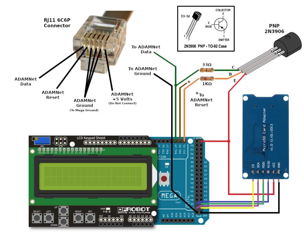 north stream
fresh pendant
does the OG AVR microcontroller in Arduino Mega not have open collector I/O? I'm...
north stream
fresh pendant
does the OG AVR microcontroller in Arduino Mega not have open collector I/O? I'm...
The I/O pins can be set to several modes, drive high, drive low, pull high, and high impedance (by setting them as inputs). An open collector behavior can be implemented by setting the output low and then switching the direction register between input (high-Z, open) and output (drive low).
fresh pendant
Based on the source code of AdamNet-Drive-Emulator, it looks like "AdamNet" is just 8N1 serial on an open collector bus, with software arbitration. My interest is in replacing the controller portion of the network so I can interface to a keyboard.
 torn panther
Can anyone provide a best practice on handling dual grounds when either developing with arduino (or similar micros) or with a finished system, where there's a potential ground loop. I've seen mention of using a device based on the ADUM3160 chip.

Mainly I'm interested in making sure my laptop is protected from any situation where it could be damaged by potential differences.
But also of course I want to avoid spurious signals that could affect proper operation of the setup
Clearly in the above example I could use a 12 V to 5V dc-dc converter, but some times that's not practical or I'm in development and don't want to deal with the extra component.
Here's an isolator device, is this suitable? https://a.co/d/4z4mRHD

HiLetgo ADUM3160 B0505S 1500V USB to USB Voltage Isolator Module Support 12Mbps 1.5Mbps
north stream
It depends on whether the DC supplies you use are isolated or not. If they're already isolated/floating, you're good to go.
torn panther
Thanks but how does one determine if a supply is isolated?
north stream
Some will be labelled, otherwise you can check for continuity between the mains plug pins and the output voltages.
torn panther
You mean literally checking static resistance with a DVM is a reliable check?
Everything nowadays is typically a switching supply, no?
as opposed to a transformer with an air gap
north stream
It's mostly reliable, but there are cheap supplies out there that don't follow all the recommended safety practices. The switching supplies use a transformer too, it's just a smaller transformer as it's operating at a higher frequency.
torn panther
I just found this: https://www.adafruit.com/product/2107

Have some USB logic analyzer, multimeter or oscilloscope and bumping up against the frustration of a shared earth ground? The Offspring (known for being electrical engineers) wisely sang ...
I think this may be a good way to go.
thanks for your help. open to any other advice you or others may have
that device's 100mA limit likely an issue for some projects but I've seen others with greater capacity.
 feral tartan
#help-with-projects message I have posted this issue, in another channel, is it okay if I link it here too?
 nova charm

This is a preprogrammed Atmega328P chip, useful if you want to make your own Arduino-compatible or repair a damaged chip on an exisiting Arduino UNO, Duemilanove, Diecimila, or NG!This chip ...
will this ever been in stock? 😭
gilded swift
nova charm
will this ever been in stock? 😭
In 104 weeks
That’s the current lead time
nova charm
awesome. (dies inside)
thanks though
i saw the digikey lead time but i thought maybe the answer would be slightly more optimistic here
north stream
nova charm
https://www.adafruit.com/product/123
How many do you need?
nova charm
around 20
north stream
I may have a tube of 25 lying around. They're blank, but I could flash bootloaders onto them
chilly plover
aliexpress seems to have some if your willing to risk it.
inland gorge
nova charm
around 20
Looks like All Electronics has some in stock https://www.allelectronics.com/item/ard-24/atmega328-w/arduino-optiboot-uno/1.html

All Electronics Corp.
An ATmega328 in DIP package, pre-loaded with the Arduino Optiboot (Uno 16MHz) Bootloader. This will allow you to use Arduino code in your custom embedded project without having to use an actual Arduino board.Atmel's ATMega328 8-Bit Processor in 28 pin DIP package. 23 I/O lines, 6 of which are channels for the 10-bit ADC. Runs up to 20MHz with ex...
nova charm
north stream
I may have a tube of 25 lying around. They're blank, but I could flash bootload...
Thanks for the offer, but I don’t think I can take them.
 supple turret
I could, but that depends on the price.
 hushed frigate
So i have an Arduino micro and an Ultimate GPS breakout v3. What program should i be running and how should i be wiring it?
solemn cliff
hushed frigate
So i have an Arduino micro and an Ultimate GPS breakout v3. What program should ...
have you looked at the learn guide ?
https://learn.adafruit.com/adafruit-ultimate-gps
 safe halo
Does anyone have any examples of using the Espressif TWAI drivers to talk over a CANBUS? I have 2 that setup as receive and Send and are using the code from the API documentation but they are not talking to each other.
 sacred ivy
This was posted on digikeys insta:
https://www.instagram.com/p/Ci0ev4xsjtM/
Is that a real arduino? Because that looks pretty sweet with the display


 unique flame
That's edited. That display looks like one of these (Adafruit #181), and they aren't the size that that display is. Also, the screws are way too small and would be going into traces.

It's almost like they expect their audience to not know what those parts are
eternal cloud
it's a stock photo of an arduino in an acrylic case, with a LCD display mounted on top (or photoshopped on)
unique flame
not to mention the wifi symbol...where is the radio there
Am I the only one having flashbacks to those stock photos of soldering? [trigger warning: unsafe soldering technique]


 deft bane
new adafruit feather nrf52840 sense not showing in arduino com port list in arduino ide. pls help
deft bane
lol nvm it was the cable i hate cables
cedar mountain
Happens way too often...
chilly plover
USB hub got me the other day. Works for most things but I couldn't upload to the mega I was using.
sacred ivy
I kind of figured it was shopped but I was also hoping it would be based off a real product.
north stream
sacred ivy
I kind of figured it was shopped but I was also hoping it would be based off a r...
You could make one... https://www.adafruit.com/product/661

These displays are small, only about 1" diagonal, but very readable due to the high contrast of an OLED display. This display is made of 128x32 individual white OLED pixels, each one is ...
sacred ivy
Honestly thats what I thought it was
north stream
Or if you wanted a tiny high rez colour display... https://www.aliexpress.com/item/3256802208624658.html

aliexpress.com
Smarter Shopping, Better Living! Aliexpress.com
livid osprey
north stream
Or if you wanted a tiny high rez colour display... https://www.aliexpress.com/it...
An arduino with a high res display? Not sure if that’s the best combination, considering the memory limitations. If we replace the arduino with a metro, though…
But holy moly that is a tiny 1080p. I assume those are probably intended for a be headset or something?
 modern seal
I can't find too many people that have experience with the USR-ES1 ethernet shield.. anyone here that does, is it a pretty good shield?
Follow up question to that, if anyone here has... I imagine it would work with the Seeduino XIAO, yes?
north stream
livid osprey
An arduino with a high res display? Not sure if that’s the best combination, con...
Yeah, it's not a realistic option for an Arduino, just an amusing thought. It would make an interesting display for a Pi Zero.
pine bramble
Ok. Odd question. Whilst using a metro esp32. I’m using a 0-5V sensor and using analogRead. When I print it to the serial monitor. Im getting a value of 1470. Maybe I’m out to lunch here
But isn’t it 1025?
cedar mountain
pine bramble
But isn’t it 1025?
The ESP32 has a 12-bit ADC, so it'll give you values of 0-4095.
pine bramble
cedar mountain
The ESP32 has a 12-bit ADC, so it'll give you values of 0-4095.
Thank you
cedar mountain
Note that it's a 3.3V chip, so you don't want to give it a full 5V signal.
pine bramble
Wait.
So if I put 5V on the analog in it kills it
I’m familiar with arduino uno boards. But wanted to step the game up here. So I got the this metro.
cedar mountain
Possibly, yes. You may be able to use a resistor divider to reduce the voltage.
 faint raft
pine bramble
Sounds like I need to find 3.3v sensors if I’m going to use this board.
faint raft
pine bramble
Sounds like I need to find 3.3v sensors if I’m going to use this board.
could you use a step-down?
pine bramble
You mean a resistor to step the voltage down?
cedar mountain
Many sensors will be happy with either voltage sometimes.
faint raft
logic level shifter is the name I was looking for
pine bramble
I will have to google that I suppose
Am sure I’m not the first person to cross this bridge
faint raft

Because the Arduino (and Basic Stamp) are 5V devices, and most modern sensors, displays, flashcards, and modes are 3.3V-only, many makers find that they need to perform level ...
cedar mountain
A level-shifter wouldn't generally help with analog sensors.
faint raft
oh, yeah, forgot that it was analog
Ed, what about this one? https://www.adafruit.com/product/395

Because the Arduino (and Basic Stamp) are 5V devices, and most modern sensors, displays, flashcards, and modes are 3.3V-only, many makers find that they need to perform level ...
pine bramble

Interesting. Here I was gonna look for a new board that maybe had the ability to still do wifi stuff but handle 5V more robustly
cedar mountain
Same. Any logic shifter only deals with 0 and 1, not intermediate analog voltages.
pine bramble
I think maybe a different sensor and or controller will do the job. Or at least the answer that’s coming into my head.
faint raft
I think I was thinking they were using like a breakout board with i2C or something, not the "raw" sensor itself, my bad, sorry for the confusion
pine bramble
Just raw sensor. Sorry I didn’t specify clearer.
 safe shell
a voltage divider as Ed suggested would be pretty easy, the 0-5V analog input range would become 0-2.5V with equal resistors (lose some precision), or you could choose resistor values to give better precision and use closer to the full 0-3.3V range
 granite lily
I had a general quesiion on arduino and arduino like products. Often times there are more pins than ports on the actual microprocessor. Does this mean that DigitalRead/Write handle dealing with muxing ?
tardy iron
granite lily
I had a general quesiion on arduino and arduino like products. Often times there...
do you have a specific example you're thinking of?
note that the term "port" as used in most MCU datasheets often means a grouping of GPIO pins that can be accessed together using a single I/O operation (though the Arduino API mostly doesn't expose this)
native dagger
tardy iron
note that the term "port" as used in most MCU datasheets often means a grouping ...
Is that operation truly simultaneous? Or is it a "for loop" of sorts under the hood?
tardy iron
native dagger
Is that operation truly simultaneous? Or is it a "for loop" of sorts under the h...
read the datasheet for details. for example, on AVR, which is an 8-bit architecture, the GPIO ports are 8 bits wide, and all bits of a port can be read or written simultaneously with a single CPU instruction
native dagger
neat
tardy iron
i think some 32-bit MCUs have GPIO ports that are 32 bits wide, though i think not all do
sometimes not all bits of a GPIO port are present on the chip pinout, and sometimes they're not even all present on the die! but this gets into all kinds of design tradeoffs that the designer makes
native dagger
by that you mean 32 GPIO per port?
solemn cliff
that did make me second guess is that all chips usually have more pins than port, so maybe the answer is: yes ?
as in: setting an individual pin is done by bitwise operations on the whole port (like changing one bit)
tardy iron
solemn cliff
that did make me second guess is that all chips usually have more pins than port...
that's why i asked for specific examples, because the terminology can be confusing that way
solemn cliff
yup
tardy iron
solemn cliff
as in: setting an individual pin is done by bitwise operations on the whole port...
yes, and on MCUs like AVR, there are special instructions that can manipulate a single port bit without doing an explicit read/write/modify at the CPU level
granite lily
The MCU i have in mind is SAMD51
#define PIN 47


void inter() {

int val = digitalRead(PIN);
digitalWrite(13, val);

}

void setup() {
  // put your setup code here, to run once:
pinMode(13, OUTPUT);
digitalWrite(13, HIGH);
delay(1000);
digitalWrite(13, LOW);
  pinMode(PIN, INPUT);
digitalWrite(51, HIGH);
//attachInterrupt(digitalPinToInterrupt(52), INT52, CHANGE);

}

void loop() {
  // put your main code here, to run repeatedly:

Serial.println(digitalRead(PIN));

}
Any idea why this just keeps outputting 1?
I connect pin 51 to pin 47 (and disconnect it, 1 no matter what)
tardy iron
granite lily
```cpp
#define PIN 47
void inter() {
int val = digitalRead(PIN);
digitalWrite...
you're only ever writing pin 51 to HIGH in setup(), and nothing inside loop() is changing it. also, you have some unused code, and stuff going on with pin 13 that you might not have wired up?
granite lily
tardy iron
you're only ever writing pin 51 to `HIGH` in `setup()`, and nothing inside `loop...
pin 13 is LED, the unused code is disabled to try to isolate the problem, the goal is that unconnecting 51 and 47 will give me 0, and connecting them will give me 1
granite lily
I tried it with , INPUT, INPUT_PULLUP, and INPUT_PULLDOWN
all 3 do the same thing except that pulldown is always 0 instead of always 1
by the way my board is a Grand Central in case thats important
tardy iron
have you checked the voltage on pin 51?
granite lily
yes I set 51 to output and got like 3.18 on that, and same with 47
tardy iron
i would suggest putting a delay in your loop() so you're not constantly flooding your serial port with output. and your serial console is set to auto-scroll?
granite lily
how do i check that auto scroll thingy,
i really should update to the non beta 2.0 ide
tardy iron
which version of the Arduino IDE?
there should be a checkbox or something on the serial console window
but i haven't used the Arduino 2.0 IDE yet
tardy iron
are you still running exactly the code you posted before? can you describe exactly what physical manipulations you're doing during your test?
granite lily
tardy iron
are you still running exactly the code you posted before? can you describe exact...
sure i have a single wire between pins 47 and 51, I start with the wire disconnected, and then connect it, and then disconnect
etc...
#define PIN 47
#define PIN_POWER 51


void inter() {

int val = digitalRead(PIN);
digitalWrite(13, val);

}

void setup() {
  // put your setup code here, to run once:
pinMode(13, OUTPUT);
digitalWrite(13, HIGH);
delay(1000);
digitalWrite(13, LOW);
  pinMode(PIN, INPUT_PULLDOWN);
digitalWrite(PIN_POWER, HIGH);
//attachInterrupt(digitalPinToInterrupt(52), INT52, CHANGE);

}

void loop() {
  // put your main code here, to run repeatedly:

Serial.println(digitalRead(PIN));
delay(1000);

}
current code im running
tardy iron
and what does it print?
tardy iron
regardless of whether 47 is wired to 51? can you show a photo of your setup with the wire in place?
granite lily
tardy iron
regardless of whether 47 is wired to 51? can you show a photo of your setup with...
sure

the green wire is the one that is in use
tardy iron
have you soldered the header pins to the board? can you show a photo of the solder joints?
granite lily
tardy iron
have you soldered the header pins to the board? can you show a photo of the sold...
sure
 tardy iron
granite lily
tardy iron
granite lily
did you intentionally only solder the pins you were planning to use?
granite lily
yep, the solder job is crude but it works for.. well at least 51 and 47. (its old solder)
I have also tried using a tipped wire to connect directly (on the back of the board) yielding 0 success
tardy iron
if you connect pin 47 to 3.3V, does it read as 1?
granite lily
HEY yeah that worked
i connected it to 5v
You think im not meating the threshold for interrupt?
tardy iron
don't do that
i'm pretty sure it's a 3.3V logic chip, so giving it 5V might damage the input buffer or other parts of the chip
eternal cloud
it is
tardy iron
did you set pinMode(51, OUTPUT) anywhere? i think digitalWrite() doesn't automatically do that
granite lily
ok wow it all of a sudden works
granite lily
tardy iron
did you set `pinMode(51, OUTPUT)` anywhere? i think `digitalWrite()` doesn't aut...
it does on SAMD platforms
which is why i never use that accursed function with timer inturrupts
😛
tardy iron
yeah, i just remembered that digitalWrite() might not change the pin mode, because setting the pin high when it's set as input is one way that you turn on pullup on AVR chips
eternal cloud
you didn't change anything in the code? and it suddenly works ?
eternal cloud
then you might reaaaaaally want to reconsider the solder job around those pins
it looks messy at best
granite lily
eternal cloud
then you might reaaaaaally want to reconsider the solder job around those pins
i mean the job is terrible so im redoing it sometime, but I dont think that was the issue, I used a different wire
tardy iron
yeah, bad jumper wires happen sometimes
granite lily
the thing is , the terrible solder job, made it so that using the back of the board did not work
eternal cloud
so do flaky solder joints, that sometimes work, and other times don't
granite lily
You may be onto something with this solder joint stuff snakey
I just used the same wire, and it worked
tardy iron
5V might have made large currents flow through the pin due to the protection diodes, so might have locally melted parts of marginal solder joints
this is not a recommended technique for solder reflow
granite lily
noice, so if i have issues with pins, just OVERvolt them
eternal cloud
that's how you meet
granite lily
Oh I made a spark Ring once, i connected 12v DC to a metal ring, like both GND and V+
roomate was anger, but not as anger as when I lit napkins on fire in a bowl
Thanks for the help guys
safe halo
I have a byte array that I am trying yo convert to a double . The number being sent is 3107. The number is being converted to an 8 byte array that is being sent is to my receiver. it is
035,012,000,000,001,000,000,000
How do I now convert these bytes back to an array?
I have tried using a memcopy to assign it but it comes back as blank.
  memcpy( &f, vals, 8 );
Serial.println(f, 0);```Could be a byte order issue
 indigo cargo
I'm starting my first foray into an LED project and I'm wondering how people go about choosing which microcontroller they use
cedar mountain
indigo cargo
I'm starting my first foray into an LED project and I'm wondering how people go ...
Familiarity from past projects is a big one. These days, in-stock availability is forcing some choices. Beyond that, specific peripheral features or hardware specs (amount of RAM, for example), or the quality of the development toolchain and available libraries.
 unreal yacht
Hello, Can somebody help me in Parsing the DataString recieved = "blhk,215,255,86,255\n"; Which i'm sending via serial to my arduino, I need to split the 4 set of integer values and assign them to separate variables
Like
int red = 215;
int green = 255;
int blue = 86;
int white = 255;

i know there is strtok method to split the character array into tokens but in my case, it's not charachter array instead it's String Format
unreal yacht
okay, nevermind, i solved it using Substring method and indexOF
cedar mountain
unreal yacht
okay, nevermind, i solved it using Substring method and indexOF
That works too. In the future, the sscanf() function for C-style strings is a good option.
pine bramble
safe shell
a voltage divider as Ed suggested would be pretty easy, the 0-5V analog input ra...
I wanted to follow up and let you know that I tried this. I had some strange readings with the sensor. So I’m unsure if it’s bad sensor or maybe something strange electrically. Going to keep messing with it
Thanks also @cedar mountain
safe shell
@pine bramble feel free to post circuit, code, or unexpected output... anything where more eyes may help
pine bramble
safe shell
<@456226577798135808> feel free to post circuit, code, or unexpected output... a...
Will do
safe halo
how do you format a number on printf to have 3 leading zeroes and 3 trailing zeroes? I have tried this but it isnt working
Serial.printf("%3.3f,%3.3f,%3.3f\n", x, y, z);
I think you use the leading zero flag (a zero first in the format specification), then set the field width to the entire thing (3 zeros before plus a radix point plus 3 zeros after would be 7 characters wide), so something like %07.3f maybe?
pine bramble
@safe shell @cedar mountain this ended up being the best way to display it as I use tinker cad on the web and haven’t dipped my toe into the fritzing tub yet.

Generic sensor I’m using.
I should specify also
I’m using the Metro328 Esp32-S2
My sketch is nothing more than analog read and serial print
But I get very strange inconsistent inputs on A0
I’m leaning on that it’s a cheap sensor but then I’m wondering too if I am missing something?
cedar mountain
pine bramble
But I get very strange inconsistent inputs on A0
Could you quantify the A0 readings you're getting? Some people have different assumptions about how much noise is unreasonable on an ADC.
pine bramble
cedar mountain
Could you quantify the A0 readings you're getting? Some people have different as...
When I get home tonight I’ll log it and show it
cedar mountain
One thing that strikes me as a little bit suspicious is that the resistors are relatively large. Depending on the chip, ADCs will usually specify a typical input impedance, since they have to draw a bit of a current from the signal to read it accurately in a short sampling time. So having too large resistors might result in distorted readings. Adding a little capacitor at the input pin to buffer the voltage might help if that's happening.
pine bramble
cedar mountain
One thing that strikes me as a little bit suspicious is that the resistors are r...
I ended up on those values because reading on the arduino forum there was talking you go too low you’ll pull the pin to zero via the resistors. But then I’m a pretty big novice so the recommended ratio was that but using 100k on the out of the divider sort of forces you into that ratio. I also read sometimes it’s beneficial to add a cap on the input pin. But I’m guessing here that by input impedance that you’re saying, if you choke out any current on the input to the chipset it has no forward bias to the adc? Because it’s stopped flat as opposed to directly having all the current the sensor would output?
cedar mountain
pine bramble
I ended up on those values because reading on the arduino forum there was talkin...
Yes, more or less. The ADC will typically have a small internal sampling capacitor that it measures the voltage of, so to charge that capacitor, it needs to draw current through the input pin. If that current is limited because of a resistor, then the capacitor won't get a full charge during the time window available for the sample.
pine bramble
Maybe my input to the adc is too great. I will try to lower it I think I have a good selection of resistors on hand
I wouldn’t think I’m the first person to cross or burn this bridge
cedar mountain
It may not be your actual problem, just a possibility.
 whole dagger
Maybe you have to put a certain load resistance on the sensor. The sensor specs say something about that, but it really makes no sense.
 pine bramble
whole dagger
Maybe you have to put a certain load resistance on the sensor. The sensor specs ...
pine bramble
whole dagger
Maybe you have to put a certain load resistance on the sensor. The sensor specs ...
I’m suspicious those are just copy and pasted amongst the 9 billion Chinese sellers of said sensor. I did request a data sheet for it.
Really the actual fix is to buy a reputable sensor from a reputable source with proven data sheets. The issue becomes at that point I could just build a plc out of industrial hardware. That’s not a part of this experience and learn tho.
 autumn oxide
I can't get my trinket to show up on mac or windows. I tried the cord with other devices and they appear. The trinket appears in devices but not as usb.


 livid osprey
autumn oxide
I can't get my trinket to show up on mac or windows. I tried the cord with othe...
livid osprey
autumn oxide
I can't get my trinket to show up on mac or windows. I tried the cord with othe...
Try a hub or a different port?
 autumn oxide
Did both
livid osprey
Have you tried https://learn.adafruit.com/introducing-trinket and followed the boot loader and driver pages?
 autumn oxide
I did the driver part but not the bootloader drive I can't access it as a drive.
autumn oxide
I misread what you said. Yes I have gone through the bootloader pages.
tardy iron
which Trinket is it, exactly? can you link to a product page? note that there are warnings about how the bit-bang USB used by the earlier Trinkets isn't compatible with many modern computers and OSes
autumn oxide

Deprecation Warning: The Trinket bit-bang USB technique it uses doesn't work as well as it did in 2014, many modern computers won't work well. So while we still carry the Trinket so ...
I used a usb hub.
I'm using a 2012 mbp and windows 10 computer with a usb hub.
When I bought this I thought I got the m0. Once I went to use it I realized it was not.
tardy iron
i'm pretty sure that non-M0 Trinkets won't mount as USB storage devices
livid osprey
Ah. @autumn oxide were you expecting it to mount as a drive? It should not, it doesn’t have that capability by default. You’re supposed to flash it using the arduino ide or similar programming tool.
If your pc can enumerate it as a Trinket, you should be able to configure Arduino IDE to program it.
autumn oxide
Yes I was.
I want to use it as a payload injector
I wonder if I can use it for switch modchip like trinket m0
But just flash it using arduino ide instead of transferring through USB.
There are 2 uf2 files and a bin file
tardy iron
autumn oxide
There are 2 uf2 files and a bin file
where are you finding UF2 files for the plain Trinket?
livid osprey
tardy iron
where are you finding UF2 files for the plain Trinket?
No, it’s for the m0. I think his question is how to use it with the attiny trinket…
livid osprey
autumn oxide
There are 2 uf2 files and a bin file
Unfortunately you can’t use uf2 files with the trinket. The bin is a format you can flash, but if it’s built for the m0 it’s not going to work.
autumn oxide
Thr bin is used for any payload injector. But considering I can't flash the uf2 files it wouldn't work. I don't know much about stuff like this. I know a bit about the pico, arduino uno and uno based 3d printers.
Thanks for the help.
pine bramble
cedar mountain
Yes, more or less. The ADC will typically have a small internal sampling capacit...
// C++ code

int sensorPin = A0;
int delayTime = 500;
int val = 0;
float pressureCorrected;
float pressure;


void setup()
{
  //sensorVal == sensorPin;
  pinMode(sensorPin, INPUT);
  Serial.begin(9600);

}

void loop()
{

  pressure = (analogRead(sensorPin));
  pressureCorrected = (pressure-830)*0.12;
  Serial.print("Pressure - ");
  Serial.println(pressureCorrected);
  delay(delayTime);

}
Actually now that I post it I see an error
The .12 is actually the conversion for the resolution
and the 830 is the base number I took out of the sensor for zero
I have it at about 1atm or 14.4psi at open. I'm going to connect it back to my air compressor and see what it do.
I guess if you see something weird with my code do let me know.
Oh also.
I lowered the divider resistance
to 570 and 1k respectively
the number seems much more stable now. But of course thats not at any sort of load on the sensor either.
I get close to a .5-1psi differential as it floats along there.
cedar mountain
This is the 300psi sensor? I think it advertises something like a 0.2% full-scale error, so that'd be about 0.6psi.
pine bramble
yes
looking
looking at it point to point is smaller. But maybe I could slow down the readings?
cedar mountain
You might also consider reading and averaging several values.
pine bramble
Thats actually a good idea
I will have to google how to keep furthering the math in the code however. I'm a dumb sparky by trade so this is new world for me.
ok a bit of plumbing and resetting the whole setup and I'll let you know how I fare.
 cedar mountain
Let me double-check your conversion formula, hang on. The 830 offset seems weird at first glance.
pine bramble
looking with a meter mid stream I'm getting about 1.2vdc
I came up with 830 offset just leaving the sensor at atmosphere pressure.
cedar mountain
I get that it should be about psi = (value - 395) * 0.095 from the specs, but that doesn't match what you're seeing at atmospheric pressure, so that's a bit weird.
pine bramble
Yeah without the fudge factor and conversion to psi
Just raw reading at 110psi I’m getting 3869 from the analogread.
cedar mountain
That's quite odd. Maybe they sent you a 100psi sensor instead?
pine bramble
I’m wondering that.
The printed thing on the side says 300 but that means nothing
So if the metro input is good for 3.3V
And I’ve got a voltage divider at 2.5V max center potential
That’s uhh
75% of full scale
3070 would be the possible resolution?
cedar mountain
Your divider center should be higher than 2.5, since the resistors aren't even.
pine bramble
Let me measure it again to verify
cedar mountain
Should be 5V->3.2V for 570/1k, I think.
pine bramble
I think my math is correct
Assuming that VCC is going to be 5V max
But actually the sensor is 4.5Vmax
So my math is even worse
Holy crap. If that’s right my Vmax at my voltage divider is 1.53
cedar mountain
I think you have that backwards... The 1k is on the ground side, right?
pine bramble
Yes
cedar mountain
So it should be like 3.5V, not 1.5V.
 cedar mountain
Easy mistake to make. It's good to develop some intuition for which side of the divider is the majority or the minority.
pine bramble
Which at 110psi I have 1.2V to A0.
cedar mountain
I wonder if the ADC is configured to use an internal lower-voltage reference instead of the 3.3V rail by default?
pine bramble
Hmm. I will pull the data sheet on Adafruit
I don't see anything about it being other than 3.3vdc
So curiously.
hear me out here.
ah nvm
I'm running low on brain power on this one...
pine bramble
Going to contact the manufacturer. Because outside of the arduino sketch just verifying output at 150psi I should have 2.5VDC. I do not. I have about 1.8.
Faulty sensor perhaps
cedar mountain
Stupid question, did you check the 5V rail with the multimeter, just to make sure it's not being powered from 3.3V or something?
pine bramble
Interestingly enough I did
I actually abandoned the metro all together just to isolate the sensor
cedar mountain
Good thought.
pine bramble
At 110psi I’m getting 1.8V. Which isn’t even close to the 2.5V as advertised.

I’m going to start from square one on this and go back to the beginning.
Tomorrow I’ll make an excel file doing all the math clearly laid out
So I’m not working over myself
I do appreciate the help though
autumn oxide
Well I bought an m0. But is there anything useful I can use the other one for?
gilded swift
autumn oxide
Well I bought an m0. But is there anything useful I can use the other one for?
Making a simple data logger
autumn oxide
gilded swift
Making a simple data logger
Maybe, I'm kind of annoyed I accidentally bought this microcontroller. I looked up trinket m0 and I got the cheapest one according to the filter and didn't notice that the led was not in the center.
gilded swift
Admittedly you can do more in Arduino with the M0, and there’s lots you can do for optimization as well
autumn oxide
Yeah the original seems pretty useless. I have plans for the m0. It's going to be a payload injector.
north stream
It's fairly limited, but hardly useless. I've built them into several things.
livid osprey
autumn oxide
Well I bought an m0. But is there anything useful I can use the other one for?
Lots of little projects here and there, most common seems to be little wearables that light up. https://learn.adafruit.com/trinket-slash-gemma-space-invader-pendant
 north stream
I built one into this LED projector

 mild nova
Hello - I want to use this motor: https://www.adafruit.com/product/4640 -- can someone point me to the smallest controller that will power (pwm) and drive it -- usb c if possible. I don't know which microcontrollers will work. Thanks
The first step in a robotics project is to get a motor spinning. Once you've done that you quickly learn that not all motors go the same speed, even if they are the same part number! ...
 stoic scroll
Hi all, anyone has experience with M5StickC esp32 wake up feature using multiple external GPIO's? I am using esp_sleep_enable_ext1_wakeup(BIT_MASK,ESP_EXT1_WAKEUP_ALL_LOW) and BIT_MASK = 2^26+2^25 in hex but it doesn't work. However , it works if I just pass one GPIO.
cedar mountain
stoic scroll
Hi all, anyone has experience with M5StickC esp32 wake up feature using multiple...
By "doesn't work", do you mean it doesn't go to sleep, or doesn't wake up? The "all low" flag is a little bit unusual, is this the mode you want for multiple wakeup sources?
inland gorge
stoic scroll
Hi all, anyone has experience with M5StickC esp32 wake up feature using multiple...
I think maybe you should do BIT_MASK = (2**26) | (2**25) instead of what you showed. Addition can have overflow and I don't think ^ does what you expect.
A more common approach would be something like BIT_MASK= (1<<GPIO25) | (1<<GPIO26) where GPIO25 and GPIO26 are defines provided by the library
stoic scroll
cedar mountain
By "doesn't work", do you mean it doesn't go to sleep, or doesn't wake up? The "...
It doesn't wake up. I have pullups on those GPIOS and switches which go low when they are pressed.
cedar mountain
stoic scroll
It doesn't wake up. I have pullups on those GPIOS and switches which go low when...
And you're pressing both switches simultaneously to test it? (Sorry for the stupid question, I just want to be sure we're on the same page.)
stoic scroll
inland gorge
I think maybe you should do `BIT_MASK = (2**26) | (2**25)` instead of what you s...
I actually convert it to hex and do like #define BIT_MASK 0x6000000
inland gorge
stoic scroll
I actually convert it to hex and do like #define BIT_MASK 0x6000000
okay that should work then (assuming those are the right bits to set. better to use #defines from the vendor)
stoic scroll
inland gorge
okay that should work then (assuming those are the right bits to set. better to ...
The gpio here is also 36 and not 25, but that doesn't work .https://www.adafruit.com/product/4290
The ESP-32-based M5Stick-C is a wee, super portable, open-source IoT development board, like a fun-sized version of the M5Stack.Jam-packed with a Wi-Fi & Bluetooth ...
inland gorge
you could try setting all pins as wakeable like https://github.com/SensorsIot/ESP32-Deep-Sleep/blob/master/ExternalWakeUp_EXT1/ExternalWakeUp_EXT1.ino
stoic scroll
cedar mountain
And you're pressing both switches simultaneously to test it? (Sorry for the stup...
I am hoping to make it wake up when one of the buttons go low.
cedar mountain
stoic scroll
I am hoping to make it wake up when one of the buttons go low.
The "all low" flag means it waits for all of them to be pressed in this case, I think. You might need to flip the buttons to pulldowns and use the "any high" flag.
stoic scroll
cedar mountain
The "all low" flag means it waits for all of them to be pressed in this case, I ...
is there any low option ?
cedar mountain
Not that I can see, unfortunately.
stoic scroll
cedar mountain
Not that I can see, unfortunately.
how about esp_sleep_enable_ext0_wakeup(GPIO_NUM_26,LOW); and esp_sleep_enable_ext0_wakeup(GPIO_NUM_25,LOW); ?
cedar mountain
stoic scroll
how about esp_sleep_enable_ext0_wakeup(GPIO_NUM_26,LOW); and esp_sleep_enable_...
I'm not sure offhand whether those would add or whether the second call would just overwrite the first configuration.
stoic scroll
cedar mountain
I'm not sure offhand whether those would add or whether the second call would ju...
It doesn't work and not even for one pin.
 charred light
Anyone know how to fix the error below while trying to upload to a Circuit Playground Bluefruit in the Arduino IDE?
"RuntimeError: Click will abort further execution because Python was configured to use ASCII as encoding for the environment."
I've tried updating the LC_ALL and LANG variables but still getting the problem
eternal cloud
charred light
Anyone know how to fix the error below while trying to upload to a Circuit Playg...
Is this the first time you use this CPB board in Arduino ?
charred light
eternal cloud
Is this the first time you use this CPB board in Arduino ?
Yes
I'm actually preparing 10 for my students.
charred light
Yes I did
I tried it in bootloader and non bootloader mode. I've downloaded the additional board definitions and have it setup to build using the Bootloader DFU as the programmer.
charred light
eternal cloud
https://learn.adafruit.com/adafruit-circuit-playground-bluefruit/arduino-support...
Do I need to upgrade the firmware?
eternal cloud
charred light
Do I need to upgrade the firmware?
No idea unfortunately, the closest thing I could find was https://github.com/microsoft/vscode-arduino/issues/1136
I also reproduced this issue when programming the Adafruit ItsyBitsy nRF52840 Express board on the Arduino IDE 2.0 Beta. But on Arduino IDE Release 1.8.13, it works fine.
Maybe try a different version of the Arduino IDE?
Hopefully someone else saw this before and has a solution
pine bramble
@cedar mountain as an update this is what I looked at today

And @safe shell if you’re interested in my foray into cheap sensor stuff
cedar mountain
Cool. Note that the linear scaling is a little inaccurate because the sensor outputs 0.5V at 0psi, whereas you're assuming 0.0V.
pine bramble
safe shell
does it output 4.5v at 300 psi?
pine bramble
You’re right
pine bramble
safe shell
does it output 4.5v at 300 psi?
Haven’t got that far yet. I can’t get it to output 2.5 or even close to at 110
I’ll bring it with me tomorrow and put it on a real pressure calibrator and see.
pine bramble
I’m using a voltage divider to drop the voltage so it will be handled by the adc on the esp32-s2
pine bramble
safe shell
I'd start with simple psi-to-voltage data.
That’s what I’ll do tomorrow. Like a 5 point reference with a bench supply and see if the output is right
safe shell
ah, right, so 2.87 is your max input voltage
pine bramble
Yes
I wondered initially if I had just missed something in the arduino side of the world but I’m leaning on it being a faulty sensor
I was however bummed that it wasn’t 1-5V on the esp32 but that’s more my fault of spec looking than anything
safe shell
if it's linear response of voltage to PSI, and if 0.5v=0PSI and if 4.5v=300PSI, then 110PSI should be 1.47v ?
I may have missed it, but there is no datasheet showing V/PSI response for this sensor?
pine bramble
It’s listed on the Amazon page. Let me ss it

As far as actual “data sheet” ehhhh. I’m sus it’s not that accurate a thing
More of “in shenzchen I have 8000 of these dohickeys to sell”
safe shell
I think you've identified the possibilities... faulty, wrong sensor, not as to-spec as advertised. But a few across the PSI-range readings of raw voltage will sort that out
(I'm assuming no faulty fluke 😉
pine bramble
What’s funny about that
I have a degree in electronics and had to do a bunch of labs. But I followed the instructor about using their crappy “ELENCO 100” or whatever.
safe shell
it's possible, but occam's razor
pine bramble
I have such high confidence in that crappy meter that when I bought my fluke 87 to treat myself after school. I tested the source voltage with the ELENCO as a verification method for the fluke.
Meanwhile the fluke probably costs hundreds more
But that stupid crappy ELENCO never lied. Ever
It was always me not using it right
Simpson is a nice meter. ;)
My ELENCO never lied and my cheap scope never lied.
pine bramble
pine bramble
_Simpson_ is a nice meter. ;)
I’ll bet they don’t lie either
They have a nice pop out thing for if you take a measurement way overrange.
I actually bought some Simpson analog metering stuff for monitoring current on a circuit just the other day. It’s always nice stuff.
I think when you push it back in it actuates a relay.
safe shell
it's good that you build some slack into your voltage range... the esp32-s2 doesn't handle the extremes well
comt to think of it though, it may not be able to measure more than 2.6v... lemme check...
pine bramble
safe shell
it's good that you build some slack into your voltage range... the esp32-s2 does...
I wish I’d have known this when I ordered it. A simple 5V arduino wouldve done what I needed to do but the wifi seemed enticing
pine bramble
I jumped to GPIO pin 6 last night being sus of that
safe shell
a 2.5V range at 12 bits should give plenty of resolution for this sensor
precision beyond the accuracy I suspect
pine bramble
I would assume that’s the case
Honestly I’m shocked, that Adafruit doesn’t sell a similar sensor.
Wouldn’t think I’m the first to be here
cedar mountain
Not the first, but it's relatively specialized. Most people never encounter pressures higher than their car tires.
pine bramble
I could agree to that. This was really an exercise for my air compressor anyway.
Either way how this fares. I appreciate all the help
pine bramble
i have a feather esp32-s2, and i uploaded my sketch to board and seems to be working ish?... can't quite tell as there are bugs in the code.
but now the board isn't showing up as a port
it is showing up as a removal drive.
any ideas?
You may have to reinitialize it using the button for it to communicate. At least I have to with my metro 328 esp
reset button?
yeah.. that didn't work
Let me look at the guide

Have you walked through this yet?
livid osprey
@pine bramble wrong esp32
livid osprey
pine bramble
it is showing up as a removal drive.
Is there a file system visible?
pine bramble
livid osprey
<@456226577798135808> wrong esp32
Ah yes my bad. This is why I don’t try to be helpful. Lol
livid osprey
No worries, you’re certainly not the first to mix up a v2 and an s2. Not by a long shot.
pine bramble
livid osprey
Is there a file system visible?
Yes. And I can access it
livid osprey
Are there any files?
pine bramble
livid osprey
Are there any files?

the index page takes me here: https://www.adafruit.com/product/5000

What's Feather-shaped and has an ESP32-S2 WiFi module? What has a STEMMA QT connector for I2C devices? What has your favorite Espressif WiFi microcontroller and lots of Flash and RAM ...
which is the board
livid osprey
Ah, it's loading up into bootloader mode for some reason. Either the boot signal is being pulled the wrong way on power-up/reset, or something in your sketch/IDE is configured wrong.
@pine bramble If you try to upload a sketch without a port, (I believe) it should auto-detect a board in bootloader mode and upload the code anyway. You can go ahead and try again, or post more source code/screenshots if it persists.


 livid osprey
Doesn't look like a source code issue, but I don't recall seeing THAT many upload options for my ESP32-S2.
Then again, I have had some poor experiences getting esptool.py to work the way I want it to.
pine bramble
yeah. i just left it as all the defaults i didn't want to touch something wrong
livid osprey
Maybe someone with more recent experience can help?
gilded swift
pine bramble
yeah. i just left it as all the defaults i didn't want to touch something wrong
Are you on windows?
gilded swift
If you hold boot and press reset, do you get a com port under device manager?
pine bramble
hold on i will do that now

that might have done it, let me go try in ardunio
i was able to select a port, and now i'm trying to upload.
gilded swift
Sometimes on the first go you have to put it in download mode, from there it should be auto detected after you upload your sketch
pine bramble
thanks
gilded swift
Got it working?
pine bramble
yeah. i'm able to upload... i just need to figure out whats wrong me source code...
gilded swift
Awesome 😎
 hoary canopy
Has anyone played around with HamShield or ham radio on Arduino? Looks like the HamShield project is done and I don't see an alternative
north stream
hoary canopy
Has anyone played around with HamShield or ham radio on Arduino? Looks like the ...
Are you looking for a TNC or digital modes or a transceiver, or what? There are some SDR boards out there, but I don't know if an Arduino is powerful enough to run those.
hoary canopy
north stream
Are you looking for a TNC or digital modes or a transceiver, or what? There are...
Probably an FM transceiver on amateur bands. As low power as I can get it, probably no more than 2 watts. It's just so I can have small projects that I can send code using my handheld radio, and the arduino or Pi could answer back over voice modulated FM
Like if it detects a specific tone on a frequency, the arduino can control a basic robot, then answer back on the frequency
north stream
That's an interesting use case. There are some nice low-power HF transceivers out there (RockMite, etc.), but FM is less common. I hadn't been familiar with the HamShield or the AU1846 chip it uses, that was a neat little niche product. I might look into getting a low end HT and just connecting the audio/PTT to an Arduino, possibly along with a serial control link if you want the Arduino to be able to control it as well.
While the HamShield is open source, so it wouldn't be hard to get boards made, there are a lot of specialized parts on it, so it might be tricky to assemble one of your own.
Poking around, I find there are a few similar projects out there like the ArduTrx (based on Dorji or NiceRF HF modules), the Arduino Walkie Talkie (based on NiceRF or Sunrise modules), and assorted APRS projects that could likely be leveraged for your uses (searches for APRS and Arduino bring up lots of things)
hoary canopy
A DIY HamShield is for sure an option. I've printed & assembled a few PCBs thanks to the help of the people here. Though since the main goal isn't really to assemble a PCB I would've liked to have a mostly ready board. ArduTrx also looks good. I'd have to see which one I could reasonably fabricate
It's true that it could simply be a cheap ham transceiver, with the mic in & speaker out connected to the ardunio. That would technically be all I need, no need for it to be able to change frequencies or Tx power by itself
hoary canopy
Am I right to think these modules from Adafruit are for packet (data) radio tx/rx only? Any support for voice? https://www.adafruit.com/product/3071

"You see, wire telegraph is a kind of a very, very long cat. You pull his tail in New York and his head is meowing in Los Angeles. Do you understand this? And radio operates ...
cedar mountain
Not directly, no. You could send audio as data, but that would be up to your software.
hoary canopy
Ok thank you. Then maybe a better option for me at this point would be a Pi with one of the USB transceivers
supple turret
Is that.... An Adafriut board, without a QT?!?
livid osprey
supple turret
Is that.... An Adafriut board, without a QT?!?
Yeah, it’s one of their older offerings, and has no I2C interface that would benefit from having QT.
Unless we’re looking at two different things, which is also entirely possible.
supple turret
livid osprey
Yeah, it’s one of their older offerings, and has no I2C interface that would ben...
It's SPI.
I've always fancied having a play around with LoRa, but using a Pi of some kind.
 odd fjord
supple turret
It's SPI.
odd fjord
supple turret
It's SPI.
Just to clarify, the RFM69 cannot do LoRA -- You need the RFM9x for that. Very similar boards.
supple turret
odd fjord
Just to clarify, the RFM69 cannot do LoRA -- You need the RFM9x for that. Very s...
Ahh, yes.. I was misreading
odd fjord
The "bonnets" work well on Pis https://www.adafruit.com/product/4087
as do the breakouts.
supple turret
I suppose I don't need LoRa.. but it would be nice for a toy. Lol
hoary canopy
For me the idea's a remote model rocket launcher. Setup the rocket, then walk back and enter a sequence on the ham radio. The launcher would detect that sequence and transmit back a countdown
cold lagoon
Hi its me again :). Im trying to upload an bootloader to an Attny44 which is mounted on an PCB (with no other components soldered on) Im getting this error:
avrdude: Device signature = 0x000000
avrdude: Yikes! Invalid device signature.
Double check connections and try again, or use -F to override this check.
I've already tripple checked all connections but they're fine.
inland gorge
cold lagoon
Hi its me again :). Im trying to upload an bootloader to an Attny44 which is mou...
Is the board getting power? Which programmer are you using? Many programmers do not supply power to the target, so you need to supply that separately
cold lagoon
im using an arduino uno. but the problem seems to be the pcb or the chip. i 3d printed an SOIC Clamp to programm a nother attiny44 thet was not mounted on the pcb and it worked fine
 copper laurel
Hi, it was suggested I ask for help here with the rtc+sd adalogger I have.
I'm able to make the feather m0 it's on Blink, so yay for some connectivity, but when I try to send an example from RTClib the arduino IDE just says 'uploading' endlessly. Mu claims nothing's connected at all.
pine bramble
Isn’t mu the python editor?
copper laurel
Yes- the feather says it works on either arduino ide or micropyton via Mu, so I tried both
More success with the arduino ide (Blink works on the M0)
copper laurel
the feather boards are stackable, so I've been hoping to make them actually work when stacked
rough torrent
Mu is typically used for boards that have CircuitPython installed, and Arduino and CircuitPython can't co-exist at the same time.
Can you post the full error? (make sure to enable full errors and warnings or whatever its' called in preferences during compilation and upload and then do a pastebin here)
copper laurel
The error, seens in arduino ide, is that it simply says 'uploading' and stays there, never advancing to either 'upload failed due to X' or to 'upload successful'
 swift wind
can I use the adafruit image reader library to load images from a sd card which is connected to an arduino via a sd card adapter
pine bramble
cedar mountain
Not the first, but it's relatively specialized. Most people never encounter pres...
Coming full circle to this. I set it down for a few days.
It must be either the sensor output doesn’t enjoy my voltage divider and or the input of the s2 doesn’t enjoy it either.
cedar mountain
Yikes, that 200psi point is awful...
pine bramble
Yeah. Not great is it.
Wait
Let me check my numbers again
I misclicked
I had missed a digit. Good lord
 cedar mountain
Cool, much better.
pine bramble
cedar mountain
Cool, much better.
I went ahead and ordered a metro mini 5V version and I’ll see what that yields in terms of not messing with the output. Although I’m still at a loss why the voltage divider didn’t end up working.
cedar mountain
My best guess is something funky with the ADC reference voltage, but I'm not familiar with the S2 there.
safe shell
@pine bramble What was the issue with the voltage divider? ESP32-S2 only goes to 2.5v analog in. There is also a calibration value in efuse, but it doesn't typically change the curve that much (up to ~10%).
Is this Arduino? I haven't used it for ESP32-S2, but I would hope they're using the 11dB attenuation by default (0-2.5v).
charred light
I'm still struggling with this problem. Updated locale and language variables in my terminal. I'm going crazy


Anyone have any ideas?
pine bramble
safe shell
<@456226577798135808> What was the issue with the voltage divider? ESP32-S2 only...
So, using a voltage divider I stepped it down to 2.8V max in to A0 or Pin6. But for whatever reason it didn’t look like the s2 was happy reading it even on the low end. I was using the arduino IDE yes. But my testing on the spreadsheet was with a fluke and pressure calibrator.
I would have 1/3 scale readings off of an air compressor and the readings on the metro 32-s2 were really erratic.
pine bramble
@charred light ^^
probably stuff a config file such as ~/.cshrc with a command to set the required environment variables.
charred light
They're in my .zprofile and bash_profile
pine bramble
Probably not detected so needs tweaking (change the spelling, capitalization &c.)
charred light
If I look at my locale in terminal all of the UTF options show but when I build in the Arduino IDE I get the same error. Is there a way to force environment variable in the IDE?
pine bramble
Is it an old version of CPython?
charred light
charred light
I'm still struggling with this problem. Updated locale and language variables in...
Thisis from the arduino IDE
I've only got one Python3 interpretter on this machine. The one that is bundled with xcode
pine bramble
Yeah I don't recognize that environment; the early part looks like Arduno C++ compilation, but then all of a sudden CPython shows up to say 'tada'. Platformio comes to mind, some.
charred light
Yeah, I'm pretty sure it compiles and links everything with the adafruit-nrfutil (which I think is Python) so somehow when it's opening that Python script it is not receiving my local variables
I'm downloading Arduino 1.8 to see if it builds there
pine bramble
Okay got you - I have seen some of that. In Linux I think that stuff lives below ~/.arduino15 and yeah it can be Python.
I have 132 python scripts in that subdirectory structure. ;)
I have played with it -- edited scripts found in that tree. STM32 cube had a script down there iirc and I messed with it to get it to 'go'.
The Arduino IDE was in no position to validate those scripts so it just runs them as it finds them. I don't know exactly how the hooks get installed, but you can probably modify any script in that tree.
pine bramble
;) At least you'll be able to use your time for something besides finding bugs in the dev environment. ;)
try typing pytho and hit tab two or three times, in Terminal.app. In Linux this is how I quickly discover I'm in python3.9.
silk token
hello! I am needing assistance with some code, I would try to do it the hard way and solve the issue myself but I am hosting people who's homes were caught in the hurricanes eyewall for 12 hours and my study space is occupied by speaking people who distract me, the issue is as follows:
I need to convert RFID tag information sized as uint32_t into uint8_t[4] The RDM3600 library uses uint32_t for everything but storage in EEPROM as uint8_t would be easier for me for various reasons. This is the code I have found elsewhere (SO and blogs) I have yet to test it but I wanted to run it by more experienced C/C++ coders who can point out any errors for me. I had one before the storm hit but I started writing code to begin testing various control flows and it will take some time to replicate the error.
Platform is arduino mega, I plan on using a nano for the finished product, thank you in advance for any assistance.
uint8_t convertu32_to_u8(uint32_t number_to_convert, int method){
    if (method == 1){
        uint8_t *arr;
        //uint32_t Tx_PP= 0x02F003E7;
        arr=(uint8_t*) &number_to_convert;
        return &arr;
    }
    if (method == 2){
        union {
            unsigned long the_number;
            unsigned char bytes[4];
        } Converter;
        Converter.the_number = number_to_convert;
    }
}
I swear to god they see me typing code and studying and just ignore the fact I am focusing on something else and demand my attention like entitled brats
pine bramble
safe shell
Is this Arduino? I haven't used it for ESP32-S2, but I would hope they're using ...
I’m not familiar by what you mean here.
safe shell
I haven't seen Arduino ADC code or libraries, but there is a setting in Espressif's API that affects the input voltage range https://docs.espressif.com/projects/esp-idf/en/v4.4.2/esp32s2/api-reference/peripherals/adc.html#adc-attenuation the library presumably chooses a default, imho 11dB would be the most natural to meet user expectations of wider input voltage range
safe shell
Arduino-specific doc: https://docs.espressif.com/projects/arduino-esp32/en/latest/api/adc.html I looked at the Arduino core code and I think it defaults attenuation to 11dB, which allows 0-2.5v
 junior crane
So I have a project where Adafruit itsybitsy is the controller and it is The I2C controller of a SMBus switch which controls 2 retimers
My ItsyBitsy is directly connected to the switch PCA9545A, this switch is connected to 2 retimers to Channel 3 and Channel 0. When I do the I2C scanner sketch, I get 1 I2C device address which is 0x73 because I am writing the pins D9 and D7 high, so when I do a I2C write according to Figure 8 in the Switch datasheet to the address 0x73 I am expecting to read F9 and if I run my I2C scanner sketch I should see 2 more addresses but instead I read all FF and still see only the switch address? I am asserting A0 and A1 of the switch high
This is my function to write and read to the switch
void writeSwitch(byte address,byte channel)
{
 Wire.beginTransmission(address);
 Wire.write(channel);
 Wire.endTransmission();

}

void readSwitch(byte address)
{
 byte read1;
 byte read2;
 Wire.requestFrom(address, 1); // select number of bytes to get from the device (2 bytes in this case)
 read1= Wire.read(); // read next byte from the following register
 read2=Wire.read();
// Serial.print(switch_address);
 Serial.print("First byte: ");
 Serial.println(read1,HEX);

}

How do I write the I2C code properly to ensure that I am actually writing to the peripherals? Whenever I do a read after write using the Wire library
 viral spade
can i use the feather M4 using ardunio programing to work with the LIS3MDL Triple-axis Magnetometer
safe shell
junior crane
Or is there a better channel to ask my question?
safe shell
this channel is fine, people come and go and it may take some time before someone with ideas about your question responds
eternal cloud
junior crane
My ItsyBitsy is directly connected to the switch PCA9545A, this switch is connec...
junior crane
Great I needed something like this
eternal cloud
The multiplexer is not going to assign different I2C addresses to your devices, so you can see them in the scan
it just forwards the information to the devices connected to it
fresh pendant
How do folks like Arduino IDE 2.0 so far? I'm advising a friend who's just starting, but haven't tried 2.0 myself. Their project is for esp32 if that matters.
pine bramble
fresh pendant
How do folks like Arduino IDE 2.0 so far? I'm advising a friend who's just start...
I’ve had pretty good luck with it so far. Have also been using it for a 32-s2
 wind drift
Is there a way to create large scale capacitive touch sensor? What material would I have to use for that? just a piece of aluminum foil? Or some kind of spray paint/coating?
pine bramble
fresh pendant
How do folks like Arduino IDE 2.0 so far? I'm advising a friend who's just start...
It has an editor similar to wokwi.com (which in turn is supposed to be like a popular editor 'everybody' uses, vscode or the like).
So it suggests very short completions to existing syntax as you type.
Runs on Debian Bullseye amd64. Seems a bit resource hungry when it starts up; even after quitting the arduino-ide, when restarted it seems 'faster' than on a cold start (when stuff gets swapped out to make room for it).
Compilation of an empty Uno sketch subjectively feels 'faster' than the 1.8.19 IDE does.
I would guess if /friend/ has a modern PC with 4GB RAM (or more) they'd be fine and should try it just to see which environment they like better.
livid osprey
wind drift
Is there a way to create large scale capacitive touch sensor? What material woul...
Yes, foil is pretty good for diy in the absence of conductive paint. Worth noting are some of the drawbacks of large-area capacitive sensors, as seen on page 7 of this application note from microchip: https://ww1.microchip.com/downloads/aemDocuments/documents/TXFG/ApplicationNotes/ApplicationNotes/Capacitive-Touch-Sensor-Design-Guide-DS00002934-B.pdf
wind drift
thanks!
are there any other alternatives I could use? The surface area I need t ocover is roughly an A4 or A3 sheet of paper in size
It just needs to turn on/off an LED
gilded swift
wind drift
thanks!
are there any other alternatives I could use? The surface area I need t...
I’d highly suggest using a multi-channel touch sensor
Use multiple channels and just read it’s status register which should tell you if any of the channels detect touch.
livid osprey
What is the surface reacting to?
Is it a finger touch or something else?
I know if it’s like a pressure plate designed to be stepped on, people have made momentary switches using foil and cardboard…
eternal cloud
wind drift
Is there a way to create large scale capacitive touch sensor? What material woul...
If you're interested in larger capacitive touch projects, look at people who do work in museums, or art galleries, with large scale installations
There are projects on this site, for example https://www.bareconductive.com/
https://www.bareconductive.com/blogs/resources/electric-paint-sensor-design-rules-of-thumb
They mainly give examples using their conductive paint (which is awesome), but the designs work with other conductive materials too.