#help-with-circuitpython
1 messages · Page 1 of 1 (latest)
 viral flume
 abstract turret
ov5640; QVGA (320x240)
viral flume
That's 2.3 million pixels per second. Where are you storing them?
the OV5640 datasheet isn't clear to me if the max transfer rate is with or without JPEG compression. (I'd expect with to be slower.)
I also don't know how fast an ESP32 can injest that data. but even 30 fps seems fast to me.
abstract turret
I don't have a way to calculate fps now but I got it at an acceptable rate with SVGA (800x600)
viral flume
I mean if using a larger image got you the FPS you wanted, then why not use the larger size?
abstract turret
I also switched to a different streaming approach
 wanton wigeon
Hi!
Any help is appreciated. 🙂
I've followed the steps as instructed by the wonderful Prof G in the video linked below (1), but I keep getting the error message shown in the screenshot. I am using a Pi Pico RP2040.
Is my board broken?
(1) https://www.youtube.com/watch?v=gPnyEJX0bUY&list=PLBJJ76R_ry5T3X72OIDkMOXQIdmcvSkue&index=3


Learn to use the print statement to output text to the console. We'll use the code editor at code.circuitpython.org, learn about the code.py file, code completion, color-coded printing, , and more!
Part of the playlist for Prof. John Gallaugher's university course Physical Computing: Art, Robotics, and Tech for Good. You can find the entire fr...
Reinstallation of the UF2-file a second time in the bootloader helped!

 hoary frigate
wanton wigeon
Reinstallation of the UF2-file a second time in the bootloader helped!
hoary frigate
wanton wigeon
Reinstallation of the UF2-file a second time in the bootloader helped!
So it's all working now?
wanton wigeon
So far 😅
 waxen topaz
Are there any alternatives to print debugging in CircuitPython? Currently just connecting to serial console, running my code, and checking the output. Would be nice to have a pdb equivalent so I can evaluate line by line. Any ideas?
 shrewd meadow
waxen topaz
Are there any alternatives to print debugging in CircuitPython? Currently just c...
shrewd meadow
waxen topaz
Are there any alternatives to print debugging in CircuitPython? Currently just c...
There is a new IDE named Rovari that was mentioned here on discord and in the newsletter recently. I think it's not released for general use yet but there were some videos shared of a debugger feature in it. Keep an eye out for that and it maybe worth a try.
As for right now one option is to utilize the REPL to execute code one line at a time. Or even combine local files with the REPL to run a program up to a certain point and then have live REPL access to instpect variables or run whatever is needed next to see how it behaves. You can save the "setup" portion of your code in a file like "start.py" or whatever name you want and then in the REPL run it with import start. The code inside of it will execute and assuming it doesn't contain an infinite loop the REPL will get control afterward with all of the variables and functions from start available.
waxen topaz
@hot bison a couple questions on the ANCS library (going off of the docs):
- is the property
active_notificationsequivalent to "notifications already in ANCS since connection was established between my peripheral and iOS" ? - Each notification has a boolean property "removed" to signal they have been cleared from the iOS device, but I'm seeing that the
wait_for_new_notificationsfn only returns a generator for new active notifications, and theactive_notificationsdict only returns, well, notifications that have not been cleared. Is this property just inherited from the ANCS Specification or is there a way to get notifications that were visible, but have since been cleared?
 hot bison
it's been a while since I used it
I think it was meant to show the current state
I was using it on my CP watch
I've switched to android now though...
waxen topaz
Looks like these lines handle "removed notifications" state, but it sets the removed attribute on a notif to true and then deletes the notif altogether lol
https://github.com/adafruit/Adafruit_CircuitPython_BLE_Apple_Notification_Center/blob/main/adafruit_ble_apple_notification_center.py#L253
hot bison
right, in case you have your own copy of the notification still
 fresh merlin
Hey, im currently trying to get an ST7735R SPI display working on my xiao rp2040, and im currently running the circuitpython 10.1.4 release from the circuitpython website.
i've managed to get everything working for the most part but as soon as i try to load the fourwire module, it seems to be missing
has this module been deprecated in the newer versions of circuitpython, or am i missing something
 abstract wedge
it should be there, what is the exact error you are getting?
fresh merlin
in the init for my display i'm calling this function:
display_bus = displayio.FourWire(
it's returning this error
AttributeError: 'module' object has no attribute 'FourWire'
abstract wedge
do you have a file anywhere on your CIRCUITPY drive called fourwire.py or fourwire.mpy?
ah, sorry, no
shrewd meadow
fourwire moved to it's own module instead of displayio I believe.
abstract wedge
ignore that
what @shrewd meadow says, you have to do import fourwire and then fourwire.FourWire(
fresh merlin
that seems to have fixed it, thanks @abstract wedge & @shrewd meadow , i was stuck at that for longer than i'd like to admit 😅
shrewd meadow
@fresh merlin did you find example code somewhere with the displayio import in it? If so please link to it so we can get it corrected.
fresh merlin
shrewd meadow
<@143426192756834304> did you find example code somewhere with the displayio imp...
I think I mistakenly carried it over from an older version of my code, since the seeed-studio provided .uf2 files are for circuitpython v7.x, and that's what I started my project on.
Everything on docs.circuitpython.org seems to point to fourwire.Fourwire() now that i'm looking at it, sorry for the inconvenience.
shrewd meadow
ok no worries. Glad you got it worked out. We did a push to get everything converted but possible some got missed so always worth a check.
hoary frigate
I have an S3 Reverse TFT Feather and I'm trying to update it from CircuitPython 9.03 to 10.x on macOS. I've tried on two different Macs, and when I drag the UF2 to it, I get the error: The operation can't be completed because the device disappeared. The other thing weird thing is that it's permantenly in bootloader mode now - if I unplug it from the Mac and plug it back in or into a different Mac, it shows up as FTHRS3BOOT, not CircuitPy. Anyone seen this happen on a Mac before?
Errors out on Windows too. Maybe something with the board?

 dense olive
staying in bootloader may mean the CircuitPython volume is corrupted, not sure why dropping a UF2 wouldn't work
(all the usual troubleshooting steps: UF2 matches the board, power and cables good, try esptool or web serial tool)
hoary frigate
Thanks for confirming - let's see if the factory test UF2 will work: https://learn.adafruit.com/esp32-s3-reverse-tft-feather/factory-reset
hoary frigate
So I get an error when trying to copy the factory test UF2, but then it does reboot and runs the test UF2 successfully. Putting it back into boot mode, I cannot copy over the normal UF2 or connect it to the "Open Installer" on its CircuitPython download page, it's unable to open a serial connection. 🤷
 lone cloud
hoary frigate
So I get an error when trying to copy the factory test UF2, but then it does reb...
lone cloud
hoary frigate
So I get an error when trying to copy the factory test UF2, but then it does reb...
IIRC there was a change to the bootloader for 10.x to change the memory mapping. Have you tried doing a full update via the website installer?
also, i had to close Chrome and restart it at one point to get the web installer to be able to use the port,..
dense olive
oh, right, the 4MB boards had the OTA partition removed
 halcyon summit
In my foolish haste, I thought that displayio.bitmap could be used for a monochrome bitmap. It can, but it doesn't do any bitpacking, so it's not actually any more memory-efficient than a bytearray, which is what I'd replaced. Thus, now I'm wondering:
- If there's a different builtin that's better-suited to my use-case, or
- How best I should go about adding a custom extension—is there a Cython-like facility, for example? Or am I going to be rolling my own .UF2?
 sick cairn
There is an mpy compiler or you can add features to the UF2
It depends whether you want to implement in C or Python
halcyon summit
I'm looking for the perf of C, but I'd certainly welcome the ability to implement in Python. I've seen .mpys floating around, but don't really know much about them. Raw bytecode?
sick cairn
Bytecode for the Python VM, yes. You build the mpy compiler as part of the toolchain for building circuitpython. Bitpacking in Python is awkward though because the integers don’t have a fixed size. So I think a C implementation is what you want.
hoary frigate
lone cloud
IIRC there was a change to the bootloader for 10.x to change the memory mapping....
Thanks - the website installer won't connect to the board when it is in FETHRBOOT mode, it's unable to open a serial connection.
lone cloud
hoary frigate
Thanks - the website installer won't connect to the board when it is in FETHRBOO...
I’m pretty sure that I had one board where I had to use esptool to do the bootloader upgrade... But I'm equally sure that I forgot the details as soon as I was done with the process. 🙂
hoary frigate
lone cloud
I’m pretty sure that I had one board where I had to use esptool to do the bootlo...
lol, I know that feeling well. 🙂
shrewd meadow
hoary frigate
Thanks - the website installer won't connect to the board when it is in FETHRBOO...
I think the website bootloader installer needs the device to be in ROM boot mode instead of normal UFT/FEATHERBOOT mode. Hold boot button and press reset instead of double press reset. Neopixels and display should remain off in ROM boot mode I believe.
hoary frigate
shrewd meadow
I think the website bootloader installer needs the device to be in ROM boot mode...
Thanks - what's weird is that my Mac wasn't seeing the Feather, but when I put it into ROM boot mode using boot and reset, it now does show FTHRS3BOOT on my Mac, but Tio still doesn't see it nor does it appear as an option in the web installer
Copying the CircuitPython UF2 still results in an error "The operation can't be completed because the device disappeared" and it reboots into FTHRS3BOOT again. 🙁
I'm gonna pivot to using a MatrixPortal for now
dense olive
ROM boot mode + esptool should work ...if not there may be something deeper going on
 dusky shard
hoary frigate
Thanks - what's weird is that my Mac wasn't seeing the Feather, but when I put i...
dusky shard
hoary frigate
Thanks - what's weird is that my Mac wasn't seeing the Feather, but when I put i...
I will second the notion that using ROM boot mode (hold boot while resetting and then release) and loading the latest bootloader combined image (using esptool usually in my case) has fixed problems and allowed me to load the UF2s using a simple copy from my Mac. I will note that even the successful UF2 copies result in the error you mentioned about the drive disappearing during copy.
halcyon summit
hoary frigate
Copying the CircuitPython UF2 still results in an error "The operation can't be ...
One reason could also be a faulty cable (or an iffy solder-job on the USB header on the board). I don't know the equivalent tool in Mac-world, but if you have a Linux machine handy, you'll see the disconnect/reconnect dance happening in dmesg.
dusky shard
hoary frigate
Thanks - what's weird is that my Mac wasn't seeing the Feather, but when I put i...
"when I put it into ROM boot mode using boot and reset, it now does show FTHRS3BOOT on my Mac"
It if was placed in ROM boot mode using boot and reset it should not show the FTHRS3BOOT. According to this page: https://learn.adafruit.com/esp32-s3-reverse-tft-feather/factory-reset#factory-reset-and-bootloader-repair-3107941
"No USB drive will appear when you've entered the ROM bootloader. This is normal!". The UF2 bootloader mode is where the FTHRS3BOOT shows up. Also when you next have it at UF2 (FTHRS3BOOT drive showing) check the INFO_UF2.TXT file. If it shows version 0.32.0 or earlier you have the wrong flash layout for Circuit Python 10.0.0+ and need to update the bootloader. (see the bottom of the page: https://circuitpython.org/board/adafruit_feather_esp32s3_reverse_tft/ ).
I've gotten pretty accustomed to using epstool because I keep switching my boards between Arduino IDE (wiping out the UF2 Bootloader) and Circuit Python. For a while I was directly flashing the Circuit Python .bin files instead of the .uf2 version but found that I liked being able to drag a different CP version when testing bugs to the FTHRS3BOOT rather than always using esptool so reflashed the uf2 bootloader (tinyuf2-adafruit_feather_esp32s3_reverse_tft-0.35.0-combined.bin) using the ROM bootloader mode.
You probably already know but any CP drive files are lost when reflashing the UF2 bootloader but are 'normally' preserved when changing CP versions by copying a CP .uf2 file to the FTHRS3BOOT drive -- backups are still a good idea.
 dusk badge
Current goal is to outline touch hotspots on a project that started with this code https://learn.adafruit.com/pyportal-alarm-clock
and led to this code
https://pastebin.com/VvgEM39Y
@ line 254 is the button section I am working on
I have read about displayio, display-shapes, display-text, and between api changes and different forum opions I am very confused

Wake up on time, see what the weather is, and start your robot coffee maker... all before getting out of bed.
Pastebin
Pastebin.com is the number one paste tool since 2002. Pastebin is a website where you can store text online for a set period of time.
no outline shows up as it is in the pastebin
sick cairn
What is your question?
dusk badge
Current goal is to outline touch hotspots
how do I outline the touch areas
?
I try reading the Adafruit learn section but everytime I think I have a solution, its old api that no longer works
posting in forum
dusk badge
I have trouble communicating sometimes I will just use forum .maybe I wont add to noise there. I know many of you are tired of me bringing this project here. I understand
sick cairn
You want to draw rectangles around the on-screen buttons?
 coral needle
Help installing circuit Phyton on HD-WF2 Its ESp32-s3 based
dense olive
@coral needle if there isn't already a board definition (https://circuitpython.org/downloads), you have two options: (1) create one; (2) find a board with similar MCU module/chip, RAM, pins, etc. ...good place to start are the Espressif dev kit boards.
dusky shard
Assuming something like a QtPy ESP32-S3 or Feather ESP32-S2/3 should I be able to see console/boot up output on the board.TX pin? Looking at the CircuitPython source it looks like the UART Console is enabled but maybe I'm mistaken on what that refers to. If not by default is there an environment variable to enable. I thought it would be nice to have a secondary way to debug -- for instance when on battery and not usb connected.
dense olive
iirc board.TX will have the debug console, which won't get much output except on reset unless DEBUG is enabled in the build
DEBUG=1
you can add additional print statements to code that will output there
dusky shard
coral needle
Help installing circuit Phyton on HD-WF2 Its ESp32-s3 based
I can confirm that often a close board download can be used if an exact match is not available. Beware of needing the same type of flash between the one you have and the one downloaded from CircuitPython. A lot of the pin definitions may be wrong (e.g. SPI, I2C, etc) so you will have to research and use direct pin numbers rather than the nice ones. For instance board.TX might be referring to the wrong pin on your board. Also things like a neopixel may not work since the pin that is on is compiled in. This note says someone 'successfully' compiled CircuitPython for the board in Feb of last year but they obviously did not submit their results back to the CircuitPython Github since it is not in there. https://github.com/mrcodetastic/ESP32-HUB75-MatrixPanel-DMA/discussions/667#discussioncomment-12040392
dusky shard
dense olive
`DEBUG=1`
Thanks a bunch -- good to know. I did add print statements to make sure my monitor system was working. So even crashes etc won't got to UART TX unless DEBUG=1?
dense olive
that is correct, must rebuild
if you are getting the reset dump of a few lines when restting the board, that's a good start
Idon't know if this is on by default on something like a QT Py, but for a dual-connector board like Espressif dev kits, reset will trigger some output lines on the alternate USB
dusky shard
I'm not desperate yet 😀 but I guess I'll need to practice my first CP build in case I need it.
As an example of wishing to have better/quicker info, sometimes there is some register dump that I miss the first part of when CP is booting (in green if I recall correctly). An always on/instantly available TX serial would capture that where the USB serial needs to fully come up to show the date.
I do have a couple of dev kits so I'll try that out. Most of my stuff is QtPy or Feather ESP32-Sx.
dense olive
looking at the QT Py learn guide, TX is GPIO5, so I'm not sure if anything goes there by default
I think there's a way to re-route console debug to another pin from default, but I'm not sure the mechanics
dusky shard
BINGO, thank you for that last insight. I don't know why I assumed that the QtPy and the Feather ESP32-S3 TX pins would act the same. The feather even says Debug next to its TX pin. I get ALL the boot stuff on the Feather while watching the TX pin. I don't have to have debug everywhere -- on my preferred platform of the feathers it is perfect!
This is a lot of the information I've wished I could get easily. Thank you!!
dense olive
P.S. if you do rebuild with DEBUG=1, you may find there's not enough room. You have to disable one or more modules in that case... ulab is a big one and sometimes enough, though it's been awhile since I've done it so I'm not sure how tight the debug build is
dusky shard
Looking closer at the Feather ESP32-S3 4MF 2MPSRAM I have there are two TX pins called out with the one on the end labeled Debug and DB on the front side of the board -- So now I see that there are two different UARTs with one having the Debug TX pin.
dense olive
I assume DB is where you're seeing the output upon reset
dusky shard
Yep.
I did find that nothing from Circuit Python operation seems to go to that port -- haven't managed a crash yet. So I guess I can't use the DB port for catching fatal errors in my CP programs with an unattached USB cable.
dense olive
not without building DEBUG=1
 warped flicker
there's no chance we can use pip packages in circuitpython, right?
https://pypi.org/project/signalrcore/
sick cairn
warped flicker
there's no chance we can use pip packages in circuitpython, right?
https://pypi....
If it’s pure python it might work.
warped flicker
even if it is, it probably relies on some stdlib stuff that cp doesn't port
i think i'll just stick to raw websockets for talking to the feathers
dusky shard
dense olive
not without building `DEBUG=1`
Thanks again for all the suggestions and help. I just built my first CP fork with DEBUG=1 and can see all the CP debugging on the Feather debug serial port.
 edgy mountain
Hey all, I'm struggling with memory allocation on a Trinket M0. I've been doing my best to rearrange code, force the garbage collector, and overall do whatever I can think of to keep memory purged and allow the code to load but I'm just failing miserably. The exact spot in code changes at times, sometimes it fails to load a library (like adafruit_ds3231) and others it fails in my code where it's trying to assign a variable.
I've also gone through the process of compiling down to .mpy and then just having the main code.py import that .mpy file but that's not helping either.
This is affecting different files as well for different functions (I'm writing a program that can do one of three things depending on what file it sees in storage). One of them has a large lookup table that I can't really reduce further than I have, another one for some reason just taps out even though the file is only about 3 kB in size.
Any suggestions would be appreciated.
 bleak tartan
GitHub
Tailscale-compatible VPN client for ESP32. Full ts2021 protocol support with WireGuard encryption, DERP relay, DISCO path discovery, and STUN. Connect your ESP32 devices to your tailnet and communi...
can this run alongside CP
dense olive
@edgy mountain You're probably aware of https://learn.adafruit.com/memory-saving-tips-for-circuitpython. The M0 boards, unfortunately, are very RAM (and flash) constrained. Would it be possible to use a more powerful processor? You could post your code and see if anyone has additional suggestions.
@bleak tartan I think you'd have to build it into the CircuitPython core, ideally as a native module with CP APIs. At first glance, it looks resource-heavy and it may be very challenging to fit it without removing other modules (perhaps many).
Another option might be to implement it on a co-processor, with some API interface to a CP library on the main processor?
edgy mountain
@dense olive Yeah, I went through pretty much everything on that page trying to get the footprint down. As it is I seem to be starting the script with only 14 kB of RAM so it appears half of it has gone to the CircuitPython environment. In my case the code is a lot of basic calculations to generate a list for generating bit patterns to send out one of the digital ports but once the list is created it's static and I delete all the other temporary variables. Even with my largest program I'm measuring about 11 kB free after loading libraries for board, time, adafruit_ticks, and digitalio (so a total of 2 kB consumption).
But the biggest problem is wanting to use the DS3231 for RTC functions in my application. As soon as I load that library I'm out of RAM. I finally tested it and simply loading the library tries to allocate over 12 kB of RAM and I'm already short. I'm sure it's a combination of many of its dependencies, too, but that's amazingly large compared to some of the other libraries. Given that much RAM allocation I couldn't even really run something else with the RTC, too, because I only have 14 kB to start. Maybe that library needs some major refactoring and cleanup?
dense olive
the DS3231 library itself looks fairly light, and only imports what it needs from bus_device and register, so maybe those are large (I wouldn't be surprised if I2C takes a chunk)
edgy mountain
Yes that's true the DS3231 is slim since it's relying heavily on the I2C functions. However, the I2C being a heavily used library I'm a bit surprised it's so large. I would think there are ways of lightweighting it or making it more modular so that only the necessary pieces are pulled in instead of the whole thing. Either way it's unfortunate. I was using the M0 because of its low power operation and small size but I also did want the calendar on the DS3231. And the main reason for using the CircuitPython over regular C was because the M0 has the flash-drive over USB feature so I don't have to have a compiler to make changes.
dusky shard
I have a QtPy ESP32-S3 4M2PSRAM that has been running fine for months with a WiFi connection to a line of sight AP 15 feet away. All of a sudden it was completely refusing to connect to the AP. Tried other APs and SSIDs and it was just like the WiFi radio was broken "Unknown Failure 2". I upgraded the UF2 Bootloader and installed latest CP 10.1.4 and libraries and still the WiFi refused to connect. I moved everything to a brand new board taken from the plastic wrap and it immediately started working.
While playing with the 'defective' board I saw the default wifi.radio.tx_power was 20. I set it to 8 and immediately all the various WiFi tests started it working again. So the board worked with tx_power=20 for months but now is only working at a lower power. tx_power is now being set in that board's boot.py to make it usable.
Has anyone ever seen this before?
sick cairn
Never had that issue. Sounds like a thermal problem with the amplifier- maybe it gets distortion when it heats up?
 ancient crown
it could be a general issue with the power setting - but why it was working and then suddenly stopped is a mystery
is 8 the only value that works?
dusky shard
It is possible that it is running slightly hotter since it is summer in Southern Calif but I try and keep the room under 80. @ancient crown I'm trying it currently at 10 and it is working so far. I need to write some code to disconnect/reconnect and log failures.
ancient crown
ok, could be thermal related as well.
i ran into something similar when using a qt py mounted on a breadboard
had to adjust the tx_power setting to get it working
if it seems to be connecting ok with the lower setting, then that's a good solution
dusky shard
Interesting to find, it won't be enough to place the tx_power setting in boot.py only. In many of my programs I use wifi.radio.enabled=False to save power when I don't need a connection and I just found that when reenabling by setting back to True the tx_power is defaulted again to 20. So I'll have to make sure that wherever I re-enable the WiFi I set the tx_power to 15 which seems to be the sweet spot for being able to connect to WiFi.
dense olive
there's some possibility the access point(s) are changing some of their settings due to changes in the local environment
 lament peak
Hi all — I'm running CircuitPython 10.1.4 on an Adafruit Qualia ESP32-S3 driving a 3.4" 480×480 RGB TTL TFT (SQUARE34). I'm seeing screen tearing/glitching that appears to be a race between display.refresh() and the parallel RGB DMA scan.
Setup:
auto_refresh=False throughout
Single display.refresh() call per event (dirty flag pattern)
Display group has: 1 full-screen background bitmap, 1 full-screen face bitmap (480×480, pre-built with bitmaptools.blit()), a static battery icon, and ~15 labels
Telemetry refreshes every 10s, face state changes every 5s
What I've tried:
auto_refresh=True — made it worse
Reducing refresh frequency — helps, but glitch still occurs on each refresh
Expanding all bitmaps to full 480×480 to eliminate per-pixel bounds checking — helped
Baking divider lines into the background bitmap to reduce layer count — helped
Removing dynamic bitmap writes (animated battery fill) — helped
Observation: The glitch is clearly in sync with display.refresh() calls. My understanding is the ESP32-S3 RGB peripheral DMA is continuously scanning the single framebuffer while CircuitPython composites into it — no vsync or double-buffering.
Questions:
Is there a way in CircuitPython to sync a refresh with the DMA scan (vsync / frame-complete interrupt)?
Does the Qualia driver support double-buffering, or is there a roadmap for it?
Any other strategies people have used to reduce tearing on parallel RGB displays with displayio?
Thanks!
 sick cairn
Tearing on Adafruit Qualia with Square34 TFT
 pseudo elm
Hey everyone, I’m an electrical engineer specializing in PCB design (schematic + layout), and I’ve been working with clients on Fiverr since last year.
I’m looking to expand beyond Fiverr and was wondering if anyone has advice on where to find more opportunities or connect with people who need PCB/electronics work.
hot bison
pseudo elm
Hey everyone, I’m an electrical engineer specializing in PCB design (schematic +...
Please only post in one place
warped flicker
how do i make a websocket request, as a client,
from cp?
like, initiate the connection from a feather to a server
warped flicker
looking through the implementation, it doesn't look like websockets are set up to be clients, only servers
https://github.com/adafruit/Adafruit_CircuitPython_HTTPServer/blob/main/adafruit_httpserver/response.py
GitHub
Simple HTTP Server for CircuitPython. Contribute to adafruit/Adafruit_CircuitPython_HTTPServer development by creating an account on GitHub.
dense olive
@warped flicker this is from a couple of years ago, but might be starting place: https://github.com/Neradoc/websockets-for-circuitpython ...there may be other libraries out there
 silver copper
Hello, I don't know if this is the right place but I have the RP2040 Feather Adalogger with which I log data via UART onto an SD card. This setup was installed on a UAV and worked during several flights on one day. Then next day we powered it up the setup and I got the error "module object has no attribute 'SD_CLK'" and couldnt proceed with logging. This error pops up in Mu Editor for Circuit Python, I am using the same lines as in the example: https://learn.adafruit.com/adafruit-feather-rp2040-adalogger/sd-card. However when using the example script in Arduino, there is no error and the example file saves normally on the SD card. I was wondering what could be the problem? When I check the available pins, there are no pins with 'SD' in their names.
abstract wedge
silver copper
Hello, I don't know if this is the right place but I have the RP2040 Feather Ada...
the pins are defined, so they should be there, are you sure you flashed the correct uf2 for that board? https://github.com/adafruit/circuitpython/blob/main/ports/raspberrypi/boards/adafruit_feather_rp2040_adalogger/pins.c#L51
 misty sorrel
someone maybe have Adafruit Feather RP2040 with USB Type A Host?
i rly need help bcs i cant use my mouse when im im pluging it into feather
 gray cargo
silver copper
Hello, I don't know if this is the right place but I have the RP2040 Feather Ada...
gray cargo
silver copper
Hello, I don't know if this is the right place but I have the RP2040 Feather Ada...
Could you paste your code, and screenshot or paste the output you are seeing, including the startup prompts? Are you doing board.SD_CLK? Did you load a new UF2? In Mu, are you sure you are running the code on the board, or maybe you are accidentally trying to run the code on the host computer under Blinka?
silver copper
abstract wedge
the pins are defined, so they should be there, are you sure you flashed the corr...
I can describe this situation in more detail so you have more context. I have used this board as a logger for a sensor on a UAV. First, I have tested in laboratory conditions. Then we went to field measurements. The first day, everything work as expected, i.e. I plugged the board to the computer to send it time (I don't have a clock or a gps module yet, so this is a workaround), and make sure that the data is saving, then I plug a li-po battery and unplug the board from the computer. Then After the UAV lands, I disconnect the board from the battery and take the SD card to the computer to download the data. I have done it before in the lab many times. My code (which I can upload tomorrow since I don't have discord at my work computer) has a data buffer so the data is saved every x seconds so I minimise the probability of corrupting the data.
So after one day of flying, I went to sleep and went with the same procedure Ive done before. I have not changed any uf2 file or any code, it was all the same. However, when I plugged in the board to the computer to load the time it looked like the board reset because I could see the uf2 folder, and I don't exactly remember how it went from there because I acted fast, but I remember getting the error above, but I don't remember if I flash nuked it first and then got the error but I reset the board, gave it the new uf2 and the necessary packages, and tried to run the code and it gave me the same error. I repeated it 2 times since then making sure I have the correct version, and even running the example SD code:
import os
import busio
import digitalio
import board
import storage
import adafruit_sdcard
Connect to the card and mount the filesystem.
cs = digitalio.DigitalInOut(board.SD_CS)
sd_spi = busio.SPI(board.SD_CLK, board.SD_MOSI, board.SD_MISO)
gives me the error that Attribute Error: "module" object has no atribute 'SD_CLK'
However, via arduino IDE the example SD card code worked and the example file saved normally.
abstract wedge
silver copper
I can describe this situation in more detail so you have more context. I have us...
what is the exact name of the uf2 you flashed on it?
silver copper
I need to check at my work tomorrow
silver copper
abstract wedge
what is the exact name of the uf2 you flashed on it?
Is there anything else I should check?
abstract wedge
silver copper
Is there anything else I should check?
the only hypothesis I can think of is that you flashed a uf2 for another feather, not the adalogger one, and that's why it's missing those pin definitions
make sure you use uf2 from this page https://circuitpython.org/board/adafruit_feather_rp2040_adalogger/
silver copper
I only used it from there afaik
 glass wigeon
Im trying to use asyncio with the circuit playground express board. I've installed the asyncio and adafruit_ticks libaries in the lib folder on the board but when I try to import i get this error:
Traceback (most recent call last):
File "code.py", line 1, in <module>
File "asyncio/init.py", line 16, in <module>
File "asyncio/core.py", line 17, in <module>
ImportError: no module named 'select'
What do I do to fix this
gray cargo
glass wigeon
Im trying to use asyncio with the circuit playground express board. I've install...
CPX does not support async/await because there's not enough room in the flash for the feature. See the warning box on this page: https://learn.adafruit.com/cooperative-multitasking-in-circuitpython-with-asyncio
 mortal spear
hello, i am using a nrf52840 supermini from ali express running circuit python
i want to use codedphy as like
a radio thing
but i can figure out how to use codedphy
sick cairn
mortal spear
ig u cant use circuitpy
Submit an issue. The support is already there in the Nordic SDK, it might not be hard to add to circuitpython.
mortal spear
i mean theres a lot of support for stuff in the nordic and zephyr sdk that isnt supported in circuitpy
its probably more work to add it to corcuitpy
also i might not have enough flash space for circuitpy to be viable for my application
 lucid atlas
WIll the busio.uart method reset_input_buffer() flush all chars from the input buffer or do I need to write my own function to do this using in_waiting or just read in a loop until no chars are found?
dense olive
it should, I just tested it on RP2350
lucid atlas
dense olive
it should, I just tested it on RP2350
Thanks! I had my doubts and Gemini also indicated there was no function either. I've been trying to correct a serial to RS232 issue and suspect stray or remaining chars in the buffer.
dense olive
there are platform-dependent quirks to UART buffering (and quirks depending on whether flow control is used)... there are several levels of buffering (UART peripheral, CircuitPython software receiver_buffer_size buffer, etc.), and written and in_waiting may or may not be correct (see https://github.com/adafruit/circuitpython/issues/10621)
silver copper
abstract wedge
make sure you use uf2 from this page https://circuitpython.org/board/adafruit_fe...
Ok I managed to fix it by reinstalling the uf2 for the 4th time, however the board reset itself for unknown reason so I should keep eye for that
wanton wigeon
Hallo!
I am playing around with microcontrollers and would like to move to CircuitPython.
I have rudimentary understanding of Python due to some accidental years at university, but I am very much in the Google-copy-&-paste stage of my coding. I mainly do simple IoT's, such as ON/OFF states control of electronics through WIFI.
I have found excellent (✨) introductory material for how to code these kinds of projects using Aurdino IDE in particular online, but not for CircuitPython.
My question for you, do you have any recommended resource that does "whole project walkthroughs" of IoTs using CircuitPython?
abstract wedge
wanton wigeon
Hallo!
I am playing around with microcontrollers and would like to move to Circ...
gray cargo
wanton wigeon
Hallo!
I am playing around with microcontrollers and would like to move to Circ...
https://learn.adafruit.com/circuitpython-essentials might be a good place to start for the control details, then look at all the IoT and WiFi control projects
 subtle mantle
Hello, I'm having a problem with an STM32F411CE WeAct BlackPill with 8MB SPI flash, version 3.1. The CIRCUITPY drive isn't showing up.
I have successfully tested the following CircuitPython versions: 8.2.0, 9.2.4, 9.2.8, 9.2.9, 10.0.0, 10.0.1, 10.0.2, 10.0.3.
With CircuitPython versions 9.2.2 and 9.2.3, the CIRCUITPY drive is no longer displayed, but this is documented.
With versions greater than or equal to 10.1.1, the CIRCUITPY drive is also not displayed. Even the self-compiled versions do not work as expected.
Does anyone have any advice?
THX
gray cargo
subtle mantle
Hello, I'm having a problem with an STM32F411CE WeAct BlackPill with 8MB SPI fla...
Please open an issue: https://github.com/adafruit/circuitpython/issues/new/choose
abstract turret
this one has me scratching my head:
Aborted installing module adafruit_led_animation - not enough free space (103160 < 41984)
On a Gemma M0
Maybe the operator is just flipped in the message
 solar orchid
I think '103160' is actually a negative number that isn't getting printed correctly. The M0 boards have very little space to install additional libraries, and adafruit_led_animation is a pretty big library
abstract turret
solar orchid
I think '103160' is actually a negative number that isn't getting printed correc...
I created a pull request to make this error more descriptive.
 grand berry
Hi,
I would like to connect a USB MIDI controller to a raspberry pico/pico 2 with its USB in host mode in CirPy. I search adafruit learning guides and try some examples but they end up with a runtime error "No usb host port initialized " when it call usb.core.find(). I guess it want a 2nd usb like the rp2040 feather usb host. I know it is feasible to use the pico usb alone using tinyusb lib in arduino but I have not found yet any example with CirPy that works. Can it be done?
sick cairn
grand berry
Hi,
I would like to connect a USB MIDI controller to a raspberry pico/pico 2 wi...
Does the native USB peripheral support host mode? The USB host feather uses the PIO https://www.adafruit.com/product/5723

You're probably really used to microcontroller boards with USB, but what about a dev board with two? Two is more than one, so that makes it twice as good! And the Adafruit Feather ...
sick cairn
sick cairn
Does the native USB peripheral support host mode? The USB host feather uses the ...
But the API only seems to support the PIO method https://docs.circuitpython.org/en/latest/shared-bindings/usb_host/
I expect that using the native USB port in host mode won't cooperate with CircuitPython's USB workflow. It could possibly work with the web workflow, or you might have to take a different approach (i.e. not CircuitPython)
grand berry
Yep it works using aduino or platformio with adafruit TinyUSB, was just curious if was possible with CirPy but seems it's not
sick cairn
Sorry. I think it violates the USB spec to be a USB host and device at the same time on the same port
viral flume
OTG allows a "device port" to be a "host port", but not at the same time
sick cairn
But might be possible if you disable the USB endpoints and only program it in safe mode
You’d have to debug over UART then
viral flume
which is possible
sick cairn
You can redirect the REPL?
viral flume
but, for CP, it'd be much easier to use a board with a dedicated host port
viral flume
sick cairn
You can redirect the REPL?
yes. but it'd be a pain to access the "flash drive" to edit the code
on an RP2040, Host on PIO is the only practical"host" option when working with CP.
viral flume
grand berry
Yep it works using aduino or platformio with adafruit TinyUSB, was just curious ...
I missed your question when I started replying to @sick cairn.
My understanding is that CP does support making an RP2040 pins a HOST. However, you cannot use the Pico(2)'s USB port as a HOST port in CP.
the RP2040's dedicated USB hardware doesn't support device and host roles at the same time.
abstract turret
Every time I save code.py on my Adafruit MatrixPortal S3 and it resets I get a OSError: [Errno 5] Input/output error that sometimes persists indefinitely until I re-install CircuitPython. Sometimes hitting the reset button fixes it. It seems like I'm in a spot where I can't recover from it again without a re-flash
dense olive
@abstract turret When you save code.py, the code-re-runs, so the exception is probably coming from code.py. You can post the code and the full exception trace (showing line numbers), that will help narrow down the reason. You shouldn't need to re-install if it's code-related.
abstract turret
dense olive
<@640562270568448010> When you save `code.py`, the code-re-runs, so the exceptio...
If I reflash and copy the same code it's fine. It's an Adafruit MatrixPortal S3.
https://learn.adafruit.com/adafruit-matrixportal-s3/overview
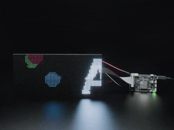
CircuitPython Powered Internet RGB Matrix Display
dense olive
It could just be that the exception is intermittent. What is the full exception trace, with line numbers?
lucid atlas
I have an rp2040 at a remote site. It is performing data capture and analysis. However, I would to record the data, perhaps up to 1 GB which is greater than the storage of the rp2040 filesystem. What solution might I use to write to a flashdrive?
sick cairn
I know there’s support for SD card storage, but I’m not sure about USB flash drives
gray cargo
abstract turret
Every time I save code.py on my Adafruit MatrixPortal S3 and it resets I get a `...
This sounds like CIRCUITPY getting corrupted. Try backing up CIRCUITPY and then doing
import storage
storage.erase_filesystem()
from the REPL.
shrewd meadow
lucid atlas
I have an rp2040 at a remote site. It is performing data capture and analysis. H...
This library is intended to support USB flash drives: https://github.com/adafruit/Adafruit_CircuitPython_USB_Host_Mass_Storage. But there is an open issue that indicates some trouble with it. I think storage is the least tested USB host functionality. Sticking to SDCard is probably a good idea. It has much better and more well tested support.
abstract turret
New night, new issue. I have several variations of the ESP32-S3 boards (Qt Py with PSRAM, Feather, etc). All of my boards work flawlessly except my 2 brand new Qt Py with no PSRAM. Neither of them can connect to wifi. I tested the same settings.toml and code.py on all other boards and it works fine.
ConnectionError: Unknown failure 2
dusky shard
I’ve had the same problem with a qtpy. You might try importing wifi in boot.py. Followed by ‘wifi.radio.tx_power=15’
I found the default of 20 would frequently cause that error. It’s worth a try anyway. Be advised that each time you reinit the WiFi (eg wake from sleep or disable/reenable WiFi you must reset power to 15 because all WiFi resets set it back to 20.
gray cargo
abstract turret
New night, new issue. I have several variations of the ESP32-S3 boards (Qt Py wi...
I would be very interested if @dusky shard 's suggestion worked for you as well.
abstract turret
@dusky shard @gray cargo that seems to have worked....
Adafruit MatrixPortal S3 Corruption
gray cargo
abstract turret
<@813601856156598273> <@329766224093249548> that seems to have worked....
Great! Could you or @dusky shard open an issue https://github.com/adafruit/circuitpython/issues/new/choose to report that this fix worked? Specify the board exactly. We have had to do this on other Qt Py boards. THe small antenna they use can get too hot, and is not that well matched to the RF output. That causes the transmitter to eventually back off power or shut down.
abstract turret
gray cargo
Great! Could you or <@813601856156598273> open an issue <https://github.com/ada...
Bug report?
gray cargo
abstract turret
Bug report?
Yes, bug report, with BobG's workaround fix. We can set the default tx_power to not be 20, and that would be the fix
abstract turret
gray cargo
abstract turret
Done - https://github.com/adafruit/circuitpython/issues/10914
thanks!
lone cloud
I want to access google calendar from an esp32s3 feather. the pyportal calendar example says This project's code uses the CircuitPython OAuth Library for authentication with Google services. Due to Google's update to the OAuth "authentication flow", the library became incompatible. As a result, this project does not currently work (but may in the future)!. It looks like something still doesn't work, can't call google_auth.request_codes(). Anyone know if there's a working way to do this?
my code is
scopes = ["https://www.googleapis.com/auth/calendar.readonly"]

google_auth = OAuth2(
    requests,
    getenv("GOOGLE_CLIENT_ID"),
    getenv("GOOGLE_CLIENT_SECRET"),
    scopes,
)

google_auth.request_codes()
using latest oauth2 via circup this morning.
i get oserror -29312.
gray cargo
lone cloud
I want to access google calendar from an esp32s3 feather. the pyportal calendar ...
I think we gave up on this because it was complicated and maybe the path to a solution was not clear.
lone cloud
🙁
gray cargo
I think we could not figure out an easy to use the OAuth flow, but I don't remember that well.
lone cloud
gray cargo
I think we could not figure out an easy to use the OAuth flow, but I don't remem...
i'm actually getting inconsistent results. most of the time i get that oserror.... but I just got a successful one.
 sick cloak
Once again a specific problem:
I have a custom PCB - close to what the RP2040 propmaker feather is.
I am able to copy the circuitpython over. But when I try to edit the code it says something about not having permission.
How do I avoid that? (Also I only see one COM port in device manager. usually there are 2)
abstract wedge
sick cloak
Once again a specific problem:
I have a custom PCB - close to what the RP2040 p...
is the drive called CIRCUITPY or something else?
sick cloak
Yes CIRCUITPY
abstract wedge
are there any files on it?
sick cloak
 abstract wedge
you can delete that uf2 file from it
sick cloak
no permission to delete eitehr 😄
abstract wedge
sounds like your operating system remounted the drive read-only, possibly because of filesystem errors, do you have access to the REPL?
sick cloak
I believ so yes
abstract wedge
you can re-format the drive by doing import storage; storage.erase_filesystem()
after that, the board should restart and your CIRCUITPY drive remount
sick cloak
hm unable to write - maybe too fast to enter REPL?
 abstract wedge
press enter in that window
 abstract wedge
that sounds like there is something wrong either with the communication with the board or the board itself...
sick cloak
hmm will try another one - I tried one before this and that worked without any problems
I am using MU for REPL (However it closes REPL when the board restarts and I need like 2-3 sec to open it again) - or is there a better option?
abstract wedge
I usually use tio
but I'm a terminal kind of person
you could also try a different usb port, different cable, with/without usb hub, etc.
dusky shard
I use tio also and it is pretty fast to connect. Also the UF2 you had on the circuit python drive. That should have been copied to the UF2 bootloader drive often something like RP2xxx. Do you have a boot button to press while powering on? Of course you can always look at boot_out.txt to see that you're running the version of CP you think you are.
sick cloak
I have boot and reset button yes
dusky shard
dejhipu's suggestion of reinitializing the disk using the REPL commands is a great first step, if that doesn't work I'd do the boot button on poweron and reload CP. Just make sure you have local copies of any files because the former will definately clear the disk and the latter may also.
sick cloak
I already tried boot + reset button.
When I try to install a different version of circuitpython it again shows a permission error.
When I use the same circuitpython version it also shows permission error.
When I remove it from USB and put it in again it seems to have installed circuitpython again and shows the CIRCUITPY drive


oh I think I got it
or half at least
was able to delete the uf2 file now
hm but now stuck again
very strange just tried another board and there circuitpython 10.1.4 it showed an error. But on 10.0.0 it worked fine
sick cloak
okay fixed it now I think.
Other PC, other USB port, other USB cable and sticking to version 10.0.0 for now
abstract wedge
it's possible there is some usb-related bug in 10.1.4...
lone cloud
what would cause CP to not reload on save? esp32s3-tft feather, 10.1.4. it's been working fine for the last day or two since i started this project, but today it's not reloading. save is fine, pressing reset gets to the new code.
gray cargo
lone cloud
what would cause CP to not reload on save? esp32s3-tft feather, 10.1.4. it's bee...
if you are at the >>> prompt it will not restart automatically. It's only if it's running.
It could be some kind of write delay going on from the host computer.
The reload is triggered by the detection of a write to CIRCUITPY. We wait 0.75 seconds (I think) after that, so that the write can complete.
lone cloud
i'm saving via vscode(windows). sometimes it works, sometimes it doesn't. can't really tell where it is in the code... usually is in a loop where there's a time.sleep(x) involved.
gray cargo
lone cloud
i'm saving via vscode(windows). sometimes it works, sometimes it doesn't. can't ...
is there an SD card attached to the board?
lone cloud
no
gray cargo
and this is 10.1.4?
lone cloud
yes
gray cargo
but if it was the same yesterday, I'm not sure I can come up with a reason. vscode is constantly updating (new version every two weeks + intermediate bugfixes). You might try another editor and see if there's any effect.
did you install anything else recently, like some drivers or a new utility program?
lone cloud
doesn't help my mood when my wifi seems to be uncooperative... starts with 'unknown error 2' when doing radio.connect, then everything i try to connect to has to have retry loop around it. timeouts, bad data in an oauth call, you name it.
nothing new that i can remember.
not since yesterday afternoon, anyway.
lone cloud
was reported on a feathers3 as well.
i'll try that, and also try downgrading to 10.0.0.3
10.0.0.3 didn't help.
gray cargo
it could be a somewhat corrupted filesystem. Backup, do storage.erase_filesystem() , and restore the backup
don't think that would explain the network problems, though
lone cloud
@hot bison is there a link to a .uf2 of the the esp-idf 6 build you mentioned in your stream? i would love to see if it helps with the wifi issues i've been having. (esp32s3 tft feather)
this is the full range of errors i'm seeing during a requests.get() on a google calendar api endpoint:
Error occurred while fetching calendar events, retrying:  [Errno 116] ETIMEDOUT
Error occurred while fetching calendar events, retrying:  -29312
Error occurred while fetching calendar events, retrying:  Out of sockets```
often takes anywhere from 10-30 repeats 1 second apart to get a successful result. sometimes makes it the first try.
lots of similar things getting time from NTP and getting tokens from oauth2, as well as various problems with `wifi.radio.connect()`.See the artifacts for this actions run: https://github.com/adafruit/circuitpython/actions/runs/23958506278

GitHub
CircuitPython - a Python implementation for teaching coding with microcontrollers - Migrate espressif port from ESP-IDF v5.5.3 to v6.0 · adafruit/circuitpython@6a34aa1
lone cloud
tyvm
hot bison
np, feel free to comment on the PR about how its going: https://github.com/adafruit/circuitpython/pull/10922
 lone cloud
will do!
hot bison
I only tested the wifi on the c6 briefly today
lone cloud
speaking of wifi... any idea what a ConnectionError with Unknown failure 2 or Unknown failure 4 means?
hot bison
you'd need to dig into the error source and figure out what enum it comes from
lone cloud
k
 real gazelle
hi, can someone help me get serial over usb for adafruit trellis m4 express working on windows / wsl2?
got it working using this: https://learn.adafruit.com/adafruit-neotrellis-m4/using-with-arduino-ide

The NeoTrellis M4 is an all-in-one USB + NeoPixel + Elastomer + Audio board.
 river shore
Hello, was hoping to find some information about ulab.utils.spectrogram in CP 10.0.0.3
I have code that is based off of: https://learn.adafruit.com/mini-led-matrix-audio-visualizer/code-the-audio-spectrum-light-show
( among a bunch of other code. )
My code sometimes crashes with an out of memory error while calling spectrogram complaining that it can't allocate 1k. I have gc.collect running every 20seconds or so, and print out the mem_free before and after. I have never seen the free value before running collect lower than 2kb, and usually it goes to 20kb afterwards.
I am calling spectrogram roughly 10 times a second. My assumption is that it is fragmentation that is causing the issue. I would like to pre-allocate the buffer for spectrogram.
Looks like ulab for micropython has a commit from 2024 that allows for a scratchpad:
https://github.com/v923z/micropython-ulab/commit/c0b3262be49de3162c9c0a7082bcd2d52907012e
I found a github repo for circuitpython ulab: https://github.com/adafruit/circuitpython-ulab but that seems to be 6 years out of date. I see issues mentioning ulab in the main circuitpython repo, but no spectrogram method. Looks like the version might be 6.5.3-2D from ulab.version?
Questions:
- Where can I look to see how ulab is included in CP?
- Is there a way I can backport the newest ulab as a separate module? Or would that be really difficult?
- Is there another way I should approach this memory issue?
shrewd meadow
river shore
Hello, was hoping to find some information about ulab.utils.spectrogram in CP 10...
ulab is connected to the circuitpython repo as a submodule inside of extmod/ https://github.com/adafruit/circuitpython/tree/main/extmod It looks like it is pointing to micropython-ulab, but is pinned to a commit older than that pre-allocation feature perhaps.
I think the new version should not be included as a separate module, but instead the existing submodule should get updated. I'm not entirely sure how the rest of the ulab/circuitpython integration works though. I do not know if/how much else there would be to do beyond updating the submodule to a newer commit and fixing any build errors and making sure the new stuff works as expected.
river shore
Ah-ha! Thanks for the link @shrewd meadow Yep, that explains what is linked. Agree that updating the extmod is the right path overall. Maybe I will see if I can set up a build environment.
Another question, is there a way to get circuit python boards into uf2 programming mode without pushing the physical button? Through a supervisor call or something? ( The code is running on assembled pieces, and it will be hard to push the reset button
shrewd meadow
river shore
Ah-ha! Thanks for the link <@382939733107408897> Yep, that explains what is lin...
There is. More details on this guide page: https://learn.adafruit.com/circuitpython-essentials/circuitpython-resetting
import microcontroller
microcontroller.on_next_reset(microcontroller.RunMode.UF2)
microcontroller.reset()
Perfect. Thank you!
shrewd meadow
yep you're welcome
solar orchid
Yes! I use this all the time as a one-liner to copy-n-paste to let me update remote CircutPython boards
import microcontroller; microcontroller.on_next_reset(microcontroller.RunMode.UF2); microcontroller.reset()
 crimson mountain
regarding the OV5640 and RP2350 feather: is there a specific GPIO that is required to output a stable clock for the XCLK input, or can it be any free GPIO? it seems like on the MEMENTO there's nothing special about the GPIO chosen but I can't find any information on what is required for this external clock
abstract wedge
import microcontroller as m; m.on_next_reset(m.RunMode.UF2); m.reset()
you can shorten it somewhat ;-)
abstract wedge
crimson mountain
regarding the OV5640 and RP2350 feather: is there a specific GPIO that is requir...
it has to support pwm
I think on the rp2350 all pins do
crimson mountain
gotcha, that goes for the xclk and the pixel clock i'm assuming?
abstract wedge
I think the pixel clock is trickier, but I don't really remember. AFAIK the camera on the rp boards is implemented using pio, so the pins need to be consecutive? But I may be wrong, it's been a while since I used it.
you don't need xclk if the camera module has an oscillator on board, by the way
crimson mountain
my plan was to break out the HSTX pins on the feather and use GPIO12-19 as the 8 consecutive data pins, so that (i hope) shouldn't be an issue but I have like zero experience with this HSTX bus
crimson mountain
abstract wedge
you don't need xclk if the camera module has an oscillator on board, by the way
i figured but i wasn't sure if the onboard clock wasn't stable enough or something, which is why they connect it to the microcontroller in all the examples
abstract wedge
I don't think it needs to be stable, it's just a clock for the internal processor, it doesn't need to run smooth
io is buffered anyways
looking at my own camera shield for the pi pico, the pixel clock doesn't need to be consecutive with the data pins
crimson mountain
abstract wedge
looking at my own camera shield for the pi pico, the pixel clock doesn't need to...
okay that's very good to know, thanks!
abstract wedge
this is the connections I used, and it works

but that was on the rp2040, with no hstx
crimson mountain
ok thanks! here's what i have in mind (tft is one of the 240x240 lcds with the microSD ports on the back), let me know if anything jumps out as being wrong
 crimson mountain
it is yes, it's internal to the feather
abstract wedge
I would use larger resistor values for the battery voltage monitor
you get less precision, but less discharge of the battery
100k perhaps
crimson mountain
ooo okay that's good to know too
i'll probably be hooking up a GPIO expander for buttons as well (did not realize how much the screen and camera would suck up) but that would just chain off of the i2c
abstract wedge
well, if you don't need the sd card, you can skip the miso pin for display, and you can have pull-down resistors on camera's reset and pwdn pins instead of gpio
and you can skip the backlight control if you don't need it
you can also use a shift register for buttons, the keypad module has support for it built in
it's cheaper and faster than expander
crimson mountain
abstract wedge
well, if you don't need the sd card, you can skip the miso pin for display, and ...
sd card is used to save photos taken, so i'd want to have those. good point on the reset and power down pins i forgot why i connected those
actually removing reset, pwdn, and backlight should give me 6 free GPIO (counting the 3 ADC channels i'm not using) so I might be all set there!
dusky shard
Is there a reason that CP 10.1.4's WiFi connection can still send every 10 minute updates to Adafruit IO but becomes unresponsive to Web Workflow without a physical visit to the board to press reset? Board is a UM TinyS2 but it has also happened on various Adafruit ESP32-Sx boards. And the current code is not set to sleep or disconnect WiFi.
hot bison
This sounds an issue that we have open
dusky shard
So I logged an issue with BLE Workflow #10785 and see another for unreachable after watchdog reset #10054. I'm using WiFi not BLE in this case and I don't think (but can't guarantee) that a watchdog reset occurred -- the code does have a watchdog in it. I'm not sure how to best troubleshoot since it is happening remotely with no system connected via USB. Also issue #9128 talks about user WiFi connect vs AutoConnect. This board starts out with AutoConnect but my code will detect a disconnect and do it's own connection so #9128 might be in play here.
P.S. I'm already sending to an AIO feed a log of the system start. I'm going to add the reset reason so hopefully I'll find out if it is due to watchdog or not. I'll log info against one of the open issues if I can document it still happening. Otherwise, I'm not sure what else to look for.
Added a comment to Watchdog Reset issue with details of testing. 10054 Comment
 bitter valley
Good Afternoon Everyone
I hope you all doing alright. I started a personal project, on which i am using the rp2350a4 with the 12MHz Abracon Oscillator and the W25Q128JV Flash. I designed this schematic after the hardware design guide provided by raspberry pi. Yesterday i started programming with installing by flashing the newest versing of circuitpython to the drive (from the boards i choose the standard raspberry pi pico 2), which worked. After that i tried editing the code.py file using vs code and the circuitPythonSync extension, which worked at first but after about 2 min or 2-3 saves and uploads of the code.py file, i got an error message, that the circuitpython drive is mounted read-only. I tried to reconnecting the board by unplugging and plugging in again, but i wasn't able to do anything on the drive. Im using windows 11 on my computer. I tried flashing different versions of circuitpython but i experience the same behavior every single time. I'm a bit suprised, becaused i used the rp2040 on a similar project about a year ago and never had any problems. I also tried some other things mentioned in other forums but nothing worked. Does anyone experience a similar behavior or is there a solution out there that i missed? Thanks for all your help in advance.

 sick cairn
bitter valley
Good Afternoon Everyone
I hope you all doing alright. I started a personal proje...
sick cairn
bitter valley
Good Afternoon Everyone
I hope you all doing alright. I started a personal proje...
I assume you’re not remounting “/“ as read-write in boot.py, which would cause this. Which release of circuitpython are you using? Does safe mode work?
bitter valley
i don't have a boot.py file in my circuitpython drive, and i am using the latest stable release (v10.1.4). I never got into safe mode, should i try entering safemode manually?
abstract wedge
the operating system may decide to remount a filesystem in read-only mode if it thinks it's corrupted
 twilit badge
Hi everyone! I have just finsihed soldering together a custom RP2350 project. It boots ok and I'd like to use Cicuit Python, but when I went to the website, I realized I don't know which uF2 to download because this is not a Circuit Python board, but something custom. Should I just pick any file or try to find the most similar one with respect to GPIOs and such?
 sick cairn
twilit badge
Hi everyone! I have just finsihed soldering together a custom RP2350 project. It...
sick cairn
twilit badge
Hi everyone! I have just finsihed soldering together a custom RP2350 project. It...
The pico 2 is a good choice, or you can make your own board definition
Are you going to share schematics and tell us what interesting things you’re doing?
sick cairn
In the circuitpython project, look under ports/raspberrypi/boards
Rp2350 is one of the faster builds, but it’s still easier in Linux
twilit badge
I am actually planning on making a video talking about this board. But it's a model rocket flight computer I tried to use AI to design. It went horribly - so AI is not really ready for even simple 4 layer boards haha. It ended up taking me way more time than if I just did it myself in KiCAD.
I just shared some info on the previous computer in #show-and-tell
This is good news so far!
 warm umbra
Added a 'mouse wiggler' to my LED glasses project. Keeps the laptop from shutting down while my long processing runs are active.
 chrome turret
I'm doing the button tutorial on the Pico 2, and for some reason, once I press the button, it doesn't switch back to false when I let go. Cant seem to google the problem. Anyone know why that's happening?
chrome turret
Solved it with a resistor. Not sure why the tutorial doesnt mention that.
sick cairn
Maybe they use a pull-up?
The internal pull-ups on RP2350 are known to be weak
chrome turret
I tried the tutorial in up instead of down and it worked fine. For some reason all the tutorials I've seen default to down, and dont show a resistor being used. When I search it everyone seems to be saying the pico doesnt need one.
Not sure why mine seems to be different
solar orchid
bitter valley
Good Afternoon Everyone
I hope you all doing alright. I started a personal proje...
Are you on MacOS or Windows? Macs have an issue where sometimes USB drives stop working and only a reboot of the Mac solves it.
abstract wedge
chrome turret
I tried the tutorial in up instead of down and it worked fine. For some reason a...
the old revision of the rp2350 had a hardware bug that made the internal pull-down resistors not work, the later revision of the chip fixed it, maybe you have the old revision of the chip?
chrome turret
would that not only be present on the original pico? ive got the pico 2
oh wait i see. the 2350 is the 2. that might be the case
abstract wedge
the suggested workaround is to use an external resistor
chrome turret
I bought it from a Canadian distributor that might have had old ones lying around. makes sense. would there be any downside to using the switches in up, and not using a resistor? or would that be unreliable?
i only have 2 10ks on hand lol
abstract wedge
I believe using pullups and button connecting to gnd is actually the default way most devices do it.
chrome turret
sounds good. thanks!
abstract wedge
the only downside is that you have to negate the button in code, but if you use a library like keypad, it does it for you
bitter valley
solar orchid
Are you on MacOS or Windows? Macs have an issue where sometimes USB drives stop...
im using windows 11 and i tried rebooting many times but it didn't help at all
bitter valley
sick cairn
I assume you’re *not* remounting “/“ as read-write in boot.py, which would cause...
to answer your question about safe mode, i am not able to enter safe mode, but i also don't see an advantage in this mode. As far as i understood, this mode just doesn't execute the code.py file, but thats what i would want it to do. So cloud you please explain further?
solar orchid
bitter valley
to answer your question about safe mode, i am not able to enter safe mode, but i...
 magic meteor
Foolish question with a Circuitpython board - the QTPy RP2040. It's been a long while since I've dealt with the USB-mounted CP boards. I'm connecting it to my Linux Mint machine. It worked yesterday, but now it always mounts the filesystem on the host as read-only. I can't get it to remount rw to update code...
gray cargo
magic meteor
Foolish question with a Circuitpython board - the QTPy RP2040. It's been a long ...
The CIRCUITPY filesystem is probably corrupted. Copy off anything you want to keep, and then type this in the REPL via the serial connection:
import storage
storage.erase_filesystem()
That will erase and reformat CIRCUITPY.
magic meteor
Thanks.
twilit badge
I’m bringing up a custom RP2350 board where I accidentally wired the I²C pins reversed (SCL → GP8, SDA → GP9), so CircuitPython hardware I²C throws “Invalid pins” and only bitbang I²C works. Bitbang can detect devices (0x53, 0x6A) but fails to reliably communicate with sensors (e.g., ADXL375 init fails and the bus sometimes locks), so I’m wondering if this is a CircuitPython limitation or a deeper hardware/signal integrity issue.
@sick cairn mentioned creating my own board definition, but I'm not sure I can just swap the bus definition and then I don't need to bitbang.
Chat GPT says I should use RP2350 SDK and C++ but all the code I have is for Circuit Python.
ancient crown
this is where a logic probe helps a ton. if you have one, set it up and see what the actual i2c traffic is when sensor init is failing.
if you have a pi pico board (rp2040) lying around, it could be turned into a perfectly good logic probe for i2c
gray cargo
twilit badge
I’m bringing up a custom RP2350 board where I accidentally wired the I²C pins re...
I'm not sure what you mean. Do you have I2C devices on board, and you accidentally swapped SCL and SDA? That is not fixable except by using bitbangio,because only certain RP2xxxx pins can be used for SCL and SDA. Or are you talking about external connections? Could you show the line of code that is failing?
twilit badge
Ohhh, I do have a few RP2040s around. Any guides you know of on how to create a logic probe from it @ancient crown ? THis is a cool idea.
@gray cargo There are several i2c devices onboard - a BMP384, ADXL375, and LSM6DSOXTR. They are all on the same bus.

 ancient crown
it's been...years? since i played with it. but sigrock + pulseview was the general setup
gray cargo
use backticks, not apostrophes for code
ancient crown
there should be a UF2 you can just dump on a pico RP2040
twilit badge
THis is the code I tried running:
import time
import board
from bitbangio import I2C
import adafruit_adxl37x

print('Test starting!')

# Setup BITBANG I2C (your custom pins)
i2c = I2C(scl=board.GP9, sda=board.GP8)


while not i2c.try_lock():
    pass
i2c.unlock()

# Initialize accelerometer
accelerometer = adafruit_adxl37x.ADXL375(i2c)

G_CONVERSION = 9.80665  # Convert m/s² to Gs

# Measured offsets based on stationary readings
X_OFFSET = 1.15
Y_OFFSET = 0.44
Z_OFFSET = 1.81

print("ADXL375 initialized!")

while True:
    try:
        x, y, z = accelerometer.acceleration

        x_g = (x / G_CONVERSION) - X_OFFSET
        y_g = (y / G_CONVERSION) - Y_OFFSET
        z_g = (z / G_CONVERSION) - Z_OFFSET

        print(
            f"Raw: {x:.2f} {y:.2f} {z:.2f} m/s² | "
            f"Calibrated: {x_g:.2f} {y_g:.2f} {z_g:.2f} G"
        )

    except Exception as e:
        print("Read error:", e)

    time.sleep(0.5)
Same result with the LSM, the init fails.
gray cargo
twilit badge
THis is the code I tried running:
```
import time
import board
from bitbangio im...
are you saying that BOARD.GP9 is really GPIO8, and BOARD.GP8 is really GPIO9?
the schematic doesn't look wrong, but you routed those GPIO lines to the wrong pins on the RP2350?
can you cut the traces and wire them up to reverse them?
if you have these parts on breakouts, try using bitbangio on a regular RP2350 board to connect to them to vet whether it's a software problem or not
while not i2c.try_lock():
    pass
i2c.unlock()
is unneeded
you could try varying the frequency and the clock stretch timeout. You can make the timeout much longer. But first see whether it works on a board with no pin-swap problems.
twilit badge
I am saying that Circuit Python insists that SCL must be GP9 and SDA must be GP8 - if you try to reverse them in your object definition, it says "File "code.py", line 16, in <module> ValueError: Invalid pins"
On my PCB, they are reversed.
gray cargo
that is true; it is a lmitation of RP2xxxx hardware
twilit badge
Oh, chat GPT says the hardware can do it, but it is a limitation of circuit python. But I've found chat is often wrong
gray cargo
but you said i2c = I2C(scl=board.GP9, sda=board.GP8)
so is board.GP9 not really GPIO9?
twilit badge
On my circuit, SDA = GP9 and SCL = GP8
 twilit badge
Yes, agreed, I read the datasheet backwards and messed this up
viral flume
twilit badge
Oh, chat GPT says the hardware can do it, but it is a limitation of circuit pyth...
Please do not waste time and energy asking the random word generator engineering questions. Especially for embedded platforms.
twilit badge
Now I'm trying to fix it in software
gray cargo
but then you would do i2c = bitbangio.I2C(scl=board.GP8, sda=board.GP9)
because you want to use GP8 as SCL
because you accidentally connected GP8 (not GP9) to all the SCL pins
if i understand you correclty
twilit badge
Oh this is backwards too. Let me try this
Yep, still the invalid pins error from:
import board
import busio
import adafruit_adxl37x

print('Test starting!')

# Setup I2C
i2c = busio.I2C(scl=board.GP8, sda=board.GP9)

accelerometer = adafruit_adxl37x.ADXL375(i2c)

G_CONVERSION = 9.80665  # Convert m/s² to Gs

# Measured offsets based on stationary readings
X_OFFSET = 1.15  # Adjust this based on your actual data
Y_OFFSET = 0.44
Z_OFFSET = 1.81  # Since it should be -1 G, subtract 1.81 - (-1) = 0.81

while True:
    x, y, z = accelerometer.acceleration
    x_g = (x / G_CONVERSION) - X_OFFSET
    y_g = (y / G_CONVERSION) - Y_OFFSET
    z_g = (z / G_CONVERSION) - Z_OFFSET

    print(f"Raw: {x:.2f} {y:.2f} {z:.2f} m/s² | Calibrated: {x_g:.2f} {y_g:.2f} {z_g:.2f} G")
    time.sleep(0.5)
```no, use bitbangio, not busio
busio will not work; it's pointing out the hardware limitation`
bitbangio.I2C is a completely different implementation internally than busio.I2C
twilit badge
Oh my god
.]0;ðŸcode.py | 10.1.4.\Test starting!
Raw: 11.05 2.88 8.17 m/s² | Calibrated: -0.02 -0.15 -0.98 G
Raw: 11.05 1.44 1.92 m/s² | Calibrated: -0.02 -0.29 -1.61 G
Raw: 9.13 1.44 5.77 m/s² | Calibrated: -0.22 -0.29 -1.22 G
Raw: 9.61 2.88 2.88 m/s² | Calibrated: -0.17 -0.15 -1.52 G
Raw: 10.09 3.84 5.29 m/s² | Calibrated: -0.12 -0.05 -1.27 G
Raw: 11.05 2.88 3.36 m/s² | Calibrated: -0.02 -0.15 -1.47 G
Raw: 10.09 0.96 7.21 m/s² | Calibrated: -0.12 -0.34 -1.08 G
I wish I came here first instead of the depressing 2 hours of talking with Chat GPT yesterday
gray cargo
if you must talk to an LLM, use one of the Codex or Claude models, not ChatGPT. but in general, go to a human source first if you can
we use models quite successfully to write code, but we know when they're wrong
we are the experts leading the interns
ancient crown
I wish I came here first instead of the depressing 2 hours of talking with Chat GPT yesterday
^^ need that printed on coffee mugs / tshirts 🙂
twilit badge
Seriously! I think it's easy to fall into the trap of Chat GPT knows everything, but really not always. I
looked back through the entire thread to figure out what went wrong and Chat GPT swapped my SDA/SCL lines in the definition even though I gave it to it correctly. However, I did learn about bit banging which I never heard of before so you win some, you lose some!
hot bison
twilit badge
Seriously! I think it's easy to fall into the trap of Chat GPT knows everything,...
I think we all need to fall in that trap to better use LLMs. 🙂
 surreal crane
what editor/ide do y'all prefer to use for circuitpython 10? i had wanted to use vs code, but the extension only currently supports 9.x
shrewd meadow
surreal crane
what editor/ide do y'all prefer to use for circuitpython 10? i had wanted to us...
I use PyCharm mostly. There is a guide page here https://learn.adafruit.com/welcome-to-circuitpython/pycharm-and-circuitpython that documents the things I setup within it. Though it is perhaps out of date at this point some of the settings screenshots are likely not exactly the same anymore but general concepts still apply. Prof G has a video covering the setup as well and links to more info: https://www.youtube.com/watch?v=5LoXTVGlNVU
solar orchid
surreal crane
what editor/ide do y'all prefer to use for circuitpython 10? i had wanted to us...
One approach is kinda "a la carte". For e.g., the Zed editor is quite good for Python work and then opening a Zed terminal running tio to get the serial REPL. I believe this is what JP uses for most of his workshops: https://www.youtube.com/watch?v=gAs45AOycrg
To get Zed to know CircuitPython classes, install the python packages pip3 install circuitpython-stubs, then you can do circuitpython_setboard raspberry_pi_pico2 or whatever board you have. Maybe install other CircuitPython packages you may use like pip3 install adafruit-circuitpython-displayio-ssd1306 for those little OLEDs. Oh I see FoamyGuy points to ProfG's videos and PyCharm. It's about the same idea I've described here but with PyCharm
surreal crane
thank you both!
abstract turret
surreal crane
what editor/ide do y'all prefer to use for circuitpython 10? i had wanted to us...
I use Kiro (basically VS Code) with the nRF Terminal extension which provides a decent serial terminal. The same extension should work with VS Code.
surreal crane
Thanks!
crimson mountain
currently working on loading a gif from disk and displaying it on this display https://www.adafruit.com/product/6178 on the RP2350 feather w/ the 8MB PSRAM. the gif plays but is particularly slow, i'm using the example that sends the data directly over the display bus rather than with displayio (this example https://docs.circuitpython.org/en/latest/shared-bindings/gifio/index.html). is there anything i can do to speed it up at all, or am i bottlenecked by processor speed/PSRAM speed?
'Round these parts we enjoy unusually-shaped displays. And this one certainly fits the description - it's a 1.28" diagonal TFT that comes in a round shape and contains a high ...
i haven't tried it with only displayio but i'm assuming it would be even slower that way
 compact creek
Ok I know least in version 9 of circuit python the ble didn’t work for the esp32 feather boards
compact creek
So the blue fruit iOS app connects to the circuitpython serial/repl fine
I might have to modify my script to just dump the can data to serial if it isn’t already and connect it to real dash
gray cargo
compact creek
Ok I know least in version 9 of circuit python the ble didn’t work for the esp32...
It wasn't enabled on boards with 4MB flash. That changed in 10.x.x.
lone cloud
if i've started an access point with wifi.radio.start_ap(...), how do i find out what channel the AP is actually using? I pass it a channel, but it's apparently in use so it picks a different one. i swear it used to work to call wifi.radio.ap_info.channel, but ap_info is none if it's an access point. (gonna have to go back to several old projects and see why they worked 🙂 ) (esp32s3 feather)
lone cloud
how/where do i file an issue with a docs page? from time.monotonic_ns(): "Return the time of the monotonic clock, which cannot go backward, in nanoseconds. Not available on boards without long integer support. Only use it to compare against other values from time.monotonic() during a single code run." Should say from time.monotonic_ns()?
gray cargo
lone cloud
how/where do i file an issue with a docs page? from `time.monotonic_ns()`: "Retu...
file an issue on the adafruit/circuitpython repo: the doc is in the source code. Yes, I think that's a typo.
lone cloud
and... weird numbers coming out of monotonic_ns() :
rpm = 60 * 1e9/ (time.monotonic_ns() - self.lastAnemometerTime)
is giving values 10X what's expected. at what should be 60 rpm, i'm getting time diffs of around 100,000,000 ns... which calculates to 600 rpm
lone cloud
gray cargo
file an issue on the adafruit/circuitpython repo: the doc is in the source code....
ok thx
lone cloud
i'm running two esp32s3's that talk using espnow. one sets up an access point and the other connects to it. (doing this mostly to avoid issues with the relatively closed network that they'll be running near, or i'd just have them connect to it). the first needs to connect to the external network on startup momentarily to call NTP to get the current time. it then calls wifi.radio.stop_station() and proceeds to set up the access point and turn on espnow. It all looks like it succeeds, but espnow isn't receiving any messages sent by the other side. If I don't connect and get NTP, it all works fine. I'm figuring there must be something else getting in the way. If I'm not mistaken, espnow automatically uses the current wifi.radio connection... is there something more than wifi.radio.stop_station() that I need to do to make sure it can connect? Any other ideas what might be going badly?
gray cargo
lone cloud
i'm running two esp32s3's that talk using espnow. one sets up an access point an...
If I'm not mistaken, espnow automatically uses the current wifi.radio connection
I don't think that is right. I think it is independent. You could trywifi.radio.enabled = False, for instance.
ESPNOW doesn't care about the local network
gray cargo
if you skip the NTP step, and remove any wifi setup info from settings.toml, does it work better?
lone cloud
if i skip NTP it works. current NTP code is:
        wifi.radio.stop_ap()
        wifi.radio.connect(os.getenv("CIRCUITPY_WIFI_SSID"), os.getenv("CIRCUITPY_WIFI_PASSWORD"))
        socket_pool = adafruit_connection_manager.get_radio_socketpool(wifi.radio)
        ssl_context = adafruit_connection_manager.get_radio_ssl_context(wifi.radio)
        requests = adafruit_requests.Session(socket_pool, ssl_context)

        ntp = adafruit_ntp.NTP(socket_pool, socket_timeout=30)
        dt = ntp.datetime
        rtc.RTC().datetime = dt
        wifi.radio.stop_station()
wifi.radio.enabled = False```i could just as well do it without the settings.toml part
but nothing else uses it except for this
gray cargo
if CIRCUITPY_WIFI_SSID and PASSWORD are in settings.toml, then it will autoconnect on hard reset.
lone cloud
hrm. ok.
gray cargo
if you name them something else, it will not autoconnect
you don't need the requests assignment. It's not used
not expensive, but not needed
you don't need the stop_ap() at the top either
just try the .enabled = False
lone cloud
gray cargo
just try the .enabled = False
still nothing.
i'm assuming that some network has to be set up, access point or otherwise.
gray cargo
lone cloud
i'm assuming that _some_ network has to be set up, access point or otherwise.
no, should not be necessary
lone cloud
back to MACs. 🙁
gray cargo
try the bare-bones example here: https://docs.circuitpython.org/en/latest/shared-bindings/espnow/index.html
ESPNOW does not live on top of TCP or UDP; it's much more low level. No access point, no router
lone cloud
right
i just tried turning off all wifi connections on both sides... and I get espidf.IDFError: ESP-NOW error 0x306d when trying to send a message
gray cargo
lone cloud
i just tried turning off all wifi connections on both sides... and I get `espidf...
if you use JUST the example I linked to above, no settings.toml, no messing with wifi, doe it work?
.enabled may be shutting down the radio chip or something
gray cargo
do a hard reset or power cycle
lone cloud
gray cargo
do a hard reset or power cycle
yes, example works.
lone cloud
gray cargo
ESPNOW does not live on top of TCP or UDP; it's much more low level. No access p...
if i haven't told espnow anything about the network, how does it know what channel to listen on ? the 306d error I get on the sender without connecting to wifi first is 'channel error'
lone cloud
hrm.
gray cargo
we didn't write the espnow module; it was contributed. I will look at the MicroPython version.
lone cloud
thanks
gray cargo
https://docs.micropython.org/en/latest/library/espnow.html#introduction
in the example, says:
# A WLAN interface must be active to send()/recv()
https://docs.micropython.org/en/latest/library/espnow.html#espnow-and-wifi-operation
so .... I don't know exactly what needs to be up. You don't need to be connected, but wifi.radio needs to be on. maybe wifi.radio.start_station() or .start_ap() is good enough, without connecting.
lone cloud
normally it is.
it's just if i've turned it on and off and on again that it won't receive.
gray cargo
so i'm sorry I led you astray. we don't have a wifi.radio.disconnect() API. The wifi.radio API was developed only with wifi in mind, not considering ESPNOW
lone cloud
🙂
lone cloud
gray cargo
so i'm sorry I led you astray. we don't have a `wifi.radio.disconnect()` API. Th...
looks like I was just being too thorough. I assumed that if you wanted to switch from station to AP that you should call stop_station ... not necessary, and espnow works if you don't call stop
now i just have to worry about getting permission for it to talk to NTP... it's a home-brew weather station for my wife's environmental science course... so i have to deal with the school district's network 🙂
gray cargo
lone cloud
looks like I was just being too thorough. I assumed that if you wanted to switch...
you could open an issue about this, and we can explore it in more detail. something about "allow espnow to work without being connected to a wifi network"
if you just do start_station, and never do anything else, is that good enough?
without scanning for wifi networks
or trying to connect
lone cloud
i don't scan, i know the AP name in advance. if i call wifi.radio.connect() to get to ntp, then call wifi.radio.start_ap, it works. just don't do anything to turn the first one off in between.
gray cargo
that sounds fine. Suppose you just call start_station, without connecting?
lone cloud
gray cargo
that sounds fine. Suppose you just call start_station, without connecting?
at which point? when getting ready to call ntp? (would be helpful if the start_station() docs would say what it's doing, or at least what it expects)
gray cargo
start_station happens implicitly when you connect. But suppose you were not trying to connect to NTP. is start_station() good enough to get espnow to run?
why are you doing start_ap()? Is it to specify the channel?
lone cloud
i need a network to connect to if i want to use web workflow to update code on the remote end... the base station i can plug into, the actual weather station i can't
hopefully it will never come to that, but we all know how likely THAT is.
@gray cargo how good is automatic garbage collection? say i need to read a series of json files off of the sd card, retaining just a couple of values from each. should i be manually GCing in between file reads? or is it going to happen by itself OK?
also thinking about just breaking the files up more, but it's making my head hurt. 🙂
gray cargo
lone cloud
<@329766224093249548> how good is automatic garbage collection? say i need to re...
it will happen automatically. The main reason to do it yourself is to prevent fragmentation. If for instance a large buffer is allocated, and then is not freed before the next large buffer is allocated, then both buffers have to exist briefly:
while True:
    buf = make_a_big_buf()
    # do something else
The old buffer will be garbage, but only after the assignment. On the other hand if you do this:
while True:
    buf = make_a_big_buf
    # ...
    buf = None
    gc.collect()
Then the old buf will definitely get freed and returned to free storage before it's created a second time.
We do have a number of API's that take an existing buf so you can reuse the buf immediately. But that's not always available.
lone cloud
and will probably be more responsive overall than hitting one big GC all at once.
dense olive
I may have missed it above, but channel is critical for ESP-Now... if you use wifi to connect to an AP, then the channel will be set to the AP channel, and it may not match ESP-Now
gray cargo
that is true, but there is also less garbage to scan if you do gc frequently
gray cargo
dense olive
I may have missed it above, but channel is critical for ESP-Now... if you use wi...
do you mean before or after? If you connect to an AP, then ESPNOW will use the current channel, I think. Our API doesn't allow channel setting, I think.
lone cloud
dense olive
I may have missed it above, but channel is critical for ESP-Now... if you use wi...
yes, i've known that. it helps knowing i can set peer.channel to 0 and have it just use the station/ap one
you can set channel for an AP
dense olive
there are ways to work around the channel and change it for ESP-Now
lone cloud
or at least request one
gray cargo
if either of your can think of API improvements or doc improvements, they are welcome
dense olive
later comments here https://github.com/adafruit/circuitpython/issues/7903 talk about fudging the ESP-Now channel
gray cargo
i forgot about that issue!
dense olive
it's been 3 years, my recollection could be faulty, but I thought if you set channel with AP or Monitor, then ESP-Now would use that channel ≠ 1, but I'm not positive
lone cloud
interesting... i've been using channel 2 until a few minutes about when I saw I can set it to 0...
i.e., setting peer.channel to 2 (matching what I request for the AP)
dense olive
(of course, all ESP-Now nodes need to use the same channel)
but I don't think it works to directly change channel in ESP-Now API
found my last example code... looks like I couldn't get channel changing to work by using station or monitor (or ESP-Now API), so creating an AP with a channel≠1 was the only way I knew of... once that's done, you can wifi.radio.stop_ap() but the new channel should stick then for ESP-Now (at least I think that's what used to happen)
it may have been a lucky fluke that the channel wasn't cleared when AP was stopped
lone cloud
i tell ya, AI gets a little unnerving at times. I'm not using it directly, like via claude or whatever, but the AI autocomplete in VSCode freaks me out when it completes what i was thinking before I even start typing it.
dense olive
(I don't know what effect, if any, wifi.radio.enabled = False will have if done between the AP channel-setting and the start of ESP-Now). But wifi.radio.stop_ap() was OK. _...edit: _ wifi.radio.enabled = False will revert the channel to 1.
lone cloud
@danh did anything ever come out of the need to keep the terminal from grabbing a display automatically? you'd mentioned wanting to put a flag in settings.toml or something like that.
gray cargo
lone cloud
@danh did anything ever come out of the need to keep the terminal from grabbing ...
I can't remember if there's an issue, but I have several things I want to add to settings.toml. Thanks for reminding me.
lone cloud
yw 🙂 i thought there was one for the terminal stuff. as i'm working on something with a display, it's started bugging me again. 🙂
gray cargo
also want to do "no USB SD card", no BLE wait, safe mode delay length
 split laurel
I've been using Adafruit CircuitPython boards for a while I recently bought 3 QT py s2 boards (Esp32s2) purchased through a local distributor I'm in Australia. On first connecting the boards none of them showed up on my Linux mint computer. After slow double clicking to get into I downloaded the newest UF2 for the boards after copping the file to the boot drive the drive disappears but instead of rebooting into into the CIRCUITPY Drive it reloaded as QTPYS2BOOT. so unable to program it in circuit python at the moment is there something I need to do to to enable me to boot into CIRCUITPY Drive then. Looking through the learn guide I tried to use the factory reset UF2 leaving the drive undetected by Linux
split laurel
After getting back into QTPYS2BOOT drive the info_uf2.txt file has the Tiny Bootloader 0.10.2 something I read on the lean pages said something about needing bootloader ver. 33 is this easy to do? I recoppied the newest stable version of the Uf2 to the Boot drive but still no luck any help appreciated thanks
gray cargo
split laurel
After getting back into QTPYS2BOOT drive the info_uf2.txt file has the Tiny B...
Follow the directions here carefully: https://learn.adafruit.com/adafruit-qt-py-esp32-s2/update-tinyuf2-bootloader-for-circuitpython-10-4mb-boards-only
CircuitPython 10.2.0-rc.0 is released! Please try it so we can release 10.2.0 final.
https://blog.adafruit.com/2026/04/16/circuitpython-10-2-0-rc0-released/
Highlights:
- New audiotools.SpeedChanger.
- New qspibus support for displayio.
- Stability improvements to USB SD card handling.
- Merge of MicroPython v1.27.
- Update to ESP-IDF v5.5.3.
- Many additions to the Zephyr port.
- Simulated hardware testing is now being done in the Zephyr port.
lone cloud
gray cargo
also want to do "no USB SD card", no BLE wait, safe mode delay length
re: usb SD card: my current project isn't loading the SD in windows - any idea why it wouldn't? (10.1.4)
gray cargo
lone cloud
re: usb SD card: my current project isn't loading the SD in windows - any idea w...
I did a lot of work on this in https://github.com/adafruit/circuitpython/pull/10887. You could try 10.2.0-rc.0.
It can take a number of seconds (>10 or 15 sometimes) to mount, depending on the size of the card and the number of files visible at the top level. It's slow for the host to read the card to get enough info to mount it.
lone cloud
gray cargo
I did a lot of work on this in <https://github.com/adafruit/circuitpython/pull/1...
RC doesn't seem any different.
esp32s3 n4r2 feather, 3.5" cap touch TFT wing with 32gb SD card.
gray cargo
is the card definitely being mounted in your program?
lone cloud
code is standard:
    sdcard = adafruit_sdcard.SDCard(board.SPI(), scs)
    vfs = storage.VfsFat(sdcard)
    storage.mount(vfs, "/sd")
no exceptions thrown, i do get an expected oserror 2 when trying to open a non-existent file. will try to get a file list, 1 sec
ya, file list is []
gray cargo
what is the host OS?
lone cloud
yes, it's in an asyncio loop
gray cargo
try a really simple mounting program without asyncio. Just mount it, do os.listdir() to check it's ok, then and put in a while True: time.sleep(1)
lone cloud
k
gray cargo
if that doesn't work, try a totally different computer, not windows, if you have one
lone cloud
nothing on this computer, or on win11 laptop. no non-windows, unfortunately.
compact creek
So I can see my esp32 with blue fruit app but it doesn’t show up as a can logger with other software. I’ll have to look into how to make a gatt profile to simulate what those look for.
Does the esp32 now support ble workflow in 10.0?
gray cargo
compact creek
Does the esp32 now support ble workflow in 10.0?
it should, but it could be broken too.
 summer kite
tried 10.2.0-rc.0 on a Matrix Portal S3 running a pretty active display program (lots of MQTT traffic and visual updates)... initially thrown by the os.getenv() changes (code was reading the broker's port number from settings.toml) but once I fixed that the code's been running well and ran overnight without any issues, so it's working well for me 🙂
gray cargo
summer kite
tried 10.2.0-rc.0 on a Matrix Portal S3 running a pretty active display program ...
what did you have to change about reading the port number?
were you expecting os.getenv() to return an int?
(which was a bug, basically).
supervisor.get_setting() will now return the int. os.getenv() will always return a string.
I think I checked all the Guide code for possible repercussions, but of course not user code.
summer kite
gray cargo
were you expecting `os.getenv()` to return an int?
Yup, was expecting an int, understand about that not being intended behavior. Found and fixed it already, not a real problem, the documentation was clear. rc.0 seems solid for me🙂
compact creek
So I upgraded my board to 10.1 without backing up my script….
I used Claude to knock together a pretty good replacement
But it seems to have created an issue where the ble service tries to start advertising again when a device connects
So should I call stop advertising when a connection hits
gray cargo
compact creek
So should I call stop advertising when a connection hits
advertising should stop automatically when a connection happens.Does your code look something like this? https://github.com/adafruit/Adafruit_CircuitPython_BLE/blob/main/examples/ble_uart_echo_test.py is a simple example. Also see the other examples in that directory. If something else is happening, let us know more, including which board this is.
 deep minnow
Hello,
I am having some issues with a rather unique setup. I have a Seeed Studio XIAO nrf52840 running CircuitPython 10.1.4, hooked up to a esp32 devkit 1 running NINA-fw 3.3.0 via SPI
I am able to run a simple test example from the adafruit_esp32spi repository with no issues.
However I have tried to use adafruit_esp32spi ESP_SPIcontrol create_AP and I keep getting an unknown error 0xfe
Searches on Google tell me that it's possibly a power related issue however I have tried both USB power and an external power supply with the same result.
I am unable to find any example of any usage of create_AP on the internet.
My goal is to use the esp32 as a access point to serve a webpage to control data on my nrf52840 as I was having little to no luck with BLE on either device.
My current pinout:
nrf52840 5V => esp32 VIN
nrf52840 GND => esp32 GND
nrf52840 SCK (D8) => esp32 (D18)
nrf52840 MISO (D9) => esp32 (D23)
nrf52840 MOSI (D10) => esp32 (D14)
nrf52840 CS (D2) => esp32 (D5)
nrf52840 BUSY (D3) => esp32 (D33)
nrf52840 RESET (D4) => esp32 (EN)
My current script:
from os import getenv

import adafruit_connection_manager
import adafruit_requests
import board
import busio
from digitalio import DigitalInOut
from adafruit_esp32spi import adafruit_esp32spi

ssid = getenv("CIRCUITPY_WIFI_SSID")
password = getenv("CIRCUITPY_WIFI_PASSWORD")

spi = board.SPI()
esp32_cs = DigitalInOut(board.D2)
esp32_ready = DigitalInOut(board.D3)
esp32_reset = DigitalInOut(board.D4)

esp = adafruit_esp32spi.ESP_SPIcontrol(spi, esp32_cs, esp32_ready, esp32_reset)

pool = adafruit_connection_manager.get_radio_socketpool(esp)
ssl_context = adafruit_connection_manager.get_radio_ssl_context(esp)
requests = adafruit_requests.Session(pool, ssl_context)

if esp.status == adafruit_esp32spi.WL_IDLE_STATUS:
    print("ESP32 found and in idle mode")
print("Firmware vers.", esp.firmware_version)
print("MAC addr:", ":".join("%02X" % byte for byte in esp.MAC_address))

while not esp.is_connected:
    try:
        # esp.connect_AP(ssid, password)
        esp.create_AP(ssid, password)
    except OSError as e:
        print("could not create AP, retrying: ", e)
        continue
have you tried non-ap operations? Do they work fine? If so, it's unlikely to be power. It could just be a bug.
 empty fjord
Hi Everyone, quick question.
When I have a settings.toml that has wifi and pasword for the web editor configured the code.py does not execute automatically when restarting the device only when I edit and save it.
Is this intended behaviour?
dusky shard
What version of CP are you running?
empty fjord
Latest from the main branch. CircuitPython 10.2.0-rc.0-3
dusky shard
So I'm not an official CP developer but I've filed a bug that exhibits that exact behavior as issue <url=https://github.com/adafruit/circuitpython/issues/10957#issue-4289467265"> #10957</url>. I might suggest going back to 10.1.4 unless you want to help debug 🙂

GitHub
CircuitPython version and board name Adafruit CircuitPython 10.2.0-rc.0 on 2026-04-16; Adafruit Feather ESP32-S2 TFT with ESP32S2 Adafruit CircuitPython 10.2.0-rc.0 on 2026-04-16; TinyS2 with ESP32...
empty fjord
Can't go back as I have just built my own firmware as my board was missing.
dusky shard
empty fjord
Have to test the microcontroller.reset() part.
I got it working as expected when I removed the settinggs.toml
dusky shard
Do you have storage.disable_usb_drive in boot.py? That is what got me into the wedged state. Also I found as you did that settings.toml with WiFi and Web Workflow enabled was a requirement. I think I recall you can have WiFi enabled but leave off the Web Workflow password and not trigger the issue I found. Your path into the no auto execution of code.py may be a dfferent one and if you figure it out either log a new bug or add to #10957 as you feel appropriate.
empty fjord
I didn't even had a boot.py
But I had wifi-settings and the web-ui port and password set.
Will try if I can replicate it consistently.
dusky shard
Interesting. I'll have to go back and retry my bug workflow steps.
empty fjord
dusky shard
dusky shard
So perhaps we're seeing similar stuff (except for boot.py being involved for me). To trigger the bug I found required all three of boot.py disable_usb_drive, WiFi credentials and Web Password in settings.toml. I did verify that either removing the boot.py or settings.toml resolved the bug and allowed code.py to run.
empty fjord
Hi Everyone, does anyone know if there is a CircuitPython library for image comparison?
I am trying to compare to captured images (OV camera) that are in a memoryview.
I am looking for something like OpenCVs SSMI where I can compare two images and calculate the meaningfull difference percentage and only send the images when they are different enough.
deep minnow
gray cargo
have you tried non-ap operations? Do they work fine? If so, it's unlikely to be ...
I am leaning towards bug as I got everything working in C++/Arduino
It is also possible that my board doesn't have enough memory for both circuitpython and creating an access point.
I will test all of the examples in the near future to see what I get as a result.
 proven nimbus
Hi everyone! Im in search of an RP2350 board that has a USB C connector, and I found the DFRobot Beetle RP2350 board.
Unfortunately, it's not on the official list of supported boards here: https://circuitpython.org/downloads
But it's just using the RP2350, so would there be any problems if I took the Pi Pico 2 Firmware and flashed it onto the Beetle? Is there any way for me to check without actually buying the board and trying it out?

CircuitPython supported boards.
abstract wedge
proven nimbus
Hi everyone! Im in search of an RP2350 board that has a USB C connector, and I f...
should work
gray cargo
proven nimbus
Hi everyone! Im in search of an RP2350 board that has a USB C connector, and I f...
There are quite a few RP2350 boards with USB-C among the list here: https://www.adafruit.com/search?q=rp2350, including our own Feathers, Metor. Pimoroni has Pico-shaped boards with USB-C
we have specific builds for some of them, but they vary little from the Pico 2 builds
proven nimbus
Out of curiosity, why the different builds if it's the same chip, just packaged in a different form factor?
gray cargo
proven nimbus
Out of curiosity, why the different builds if it's the same chip, just packaged ...
sometimes there is an LED on a different pin or one or more connectors. And it shows up with the proper name
many boards don't break out all the pins, and the pins they do choose to break out are different. unavailable pins are omitted on those builds
third-party board builds are often created by community members
proven nimbus
Ahh alright then, makes sense.
Thanks a lot - I'll have a look at the boards on the adafruit storefront and see which one fits my form factor.
Thanks a bunch!
lone cloud
anyone know if there's an easy way to grab glyphs (either one at a time, or passing a desired string) out of a bitmapfont? i'm using a Graph class originally descended from the one in the https://learn.adafruit.com/ez-make-oven project - it draws itself into a bitmap which goes into a tilegrid. I'm wanting to draw axis labels directly in the bitmap, instead of trying to keep displayio labels aligned in the right positions.

Make your own reflow oven with this easy to build project
shrewd meadow
lone cloud
anyone know if there's an easy way to grab glyphs (either one at a time, or pass...
The Font class has a get_glyph() function that takes an int for a codepoint of a character. It returns Glyph object that has the source bitmap and geometry values that can be used to extract the portion of the bitmap that represents that glyph. It doesn't return just the single glyph bitmap though, you have to cut out the section that represents the glyph you're interested in "manually" bitmaptools.blit() could help with that.
>>> terminalio.FONT.get_glyph(ord("a"))
Glyph(bitmap=<Bitmap>, tile_index=65, width=6, height=12, dx=0, dy=0, shift_x=6, shift_y=0)
thank you! that's exactly what I was looking for... but couldn't figure out where it was in the docs. 🙂
 cosmic swift
Random post. I am not a programmer. Today I learned I can reset a counter automatically using the % operator. Yeah not exciting to most of you, but being able to replace
count += 1
[do stuff]
if count > 150:
    count = 0
with count = (count + 1) % 151 I thought was pretty cool.
sick cairn
cosmic swift
Random post. I am not a programmer. Today I learned I can reset a counter automa...
You can also do it with bitwise AND if the denominator is a power of 2
compact creek
Should a program use a try catch for keyboard interrupt to do de init and delete?
@gray cargo it did look similar to that. It is using a esp32 huzzah v2. 8mb flash 2mb psram. It works if I have the toml set up to be ble device and add additional services and notify when I want to publish something to those services
If I remove the ble config in the toml, and use code similar to the example it sits and spins when things try to connect.
gray cargo
compact creek
<@329766224093249548> it did look similar to that. It is using a esp32 huzzah v2...
if I understand you correctly, you could use atexit. But what you are describing sounds like a bug. Try an older version, like 9.2.9 or 10.0.3.
empty fjord
Hi everyone, I have a question regarding espcamera.
I have a couple of boards that run on ESP32-S3 N16R8 and have a camera port. I was searching through the circuitpython sdkconfigs and not one single board definition has the OV3660 or OV5640 enabled. Is there a way to enable these without to recompile the firmware?
gray cargo
empty fjord
Hi everyone, I have a question regarding espcamera.
I have a couple of boards t...
See my reply here: https://github.com/adafruit/circuitpython/pull/10959#issuecomment-4297103757
empty fjord
gray cargo
See my reply here: <https://github.com/adafruit/circuitpython/pull/10959#issueco...
Thank you! Does this mean the espcamera module should be available on most of the ESP32-S3 board configs as well?
gray cargo
it is on by default in mpconfigport.mk
empty fjord
Thanks, in that case I will try the esp32s3_devkitc_1_n16 as that should have everything except the pre-defined pin mappings MP_ROM_QSTR.
gray cargo
empty fjord
Thank you! Does this mean the espcamera module should be available on most of th...
there is not an Espressif dev board build for n16r8
that n16 has no PSRAM specified, though it might be autodetected, depending on the settings.
empty fjord
Ah it is missing the psram
gray cargo
if you go to espressif/boards, this line will find all the 16/8 boards:
grep 'PSRAM_SIZE = 8MB' -l */mpconfigboard.mk |xargs grep 'FLASH_SIZE = 16MB'
for instance the metro s3 is 16/8, but it doesn't have all the pins
Espressif does not actuall make a devkit board that is 16/8
empty fjord
Yeah, I assume the ones I got a cheap knockoffs ... I already orderes some real bran ones.
the yd_esp32_s3_n16r8 seems to have the exact same pin config - Minus the camera pins and I can map the manually in the python.
Will test with this board. If that works I don't need the pull request.
empty fjord
The yd_esp32_s3_n16r8 works perfectly with custom pin-mapping in code. Thanks again!
empty fjord
I was using the really good beginners guides and tutorials at https://learn.adafruit.com/welcome-to-circuitpython/exploring-your-first-circuitpython-program to learn about circuitpython and I think what made me tumble was a simple silly missing information - that is now clear as daylight to me in hindsight.
The board.LED or board.NEOPIXEL are just alias names.
If the firmware you used for your board does not have that alias this is no big deal as you can always use the pins directly. They are either called board.IO{number} or board.GPIO{number} depending on the firmware.
Is there a way to propose a change to that tutorial?
It would be nice to mention that in the "Exploring your first program" section.
gray cargo
empty fjord
I was using the really good beginners guides and tutorials at https://learn.adaf...
That is a good suggestion. The best place to leave that feedback is to click on the "Feedback? Corrections?" link in the left sidebar in that Learn Guide. That enters it into our internal system for feedback for guides.
empty fjord
Done
dusky shard
@empty fjord Nice job figuring out the 'unknown manufacturer' pinouts for the camera board. Somewhere in these threads I think you said you found an official version. I'm not finding one easily, could you post a url I'd like to compare it with the one you currently have.
 bleak pagoda
I am trying to add the M5Stack StickS3 to CircuitPython, but I am confused what to put in board.c. What do I need to put in the board files?
gray cargo
bleak pagoda
I am trying to add the M5Stack StickS3 to CircuitPython, but I am confused what ...
normally you don't need to add anything to board.c unless you need to initialize a display or do something with a pin on startup or pin reset
bleak pagoda
gray cargo
normally you don't need to add anything to board.c unless you need to initialize...
How would I initialize its display? It appears to be a ST7789P3
gray cargo
find another board with the same display, if you can
bleak pagoda
The StickC PLUS2 has a ST7789v2
gray cargo
i don't know what the difference is. It will involve studying datasheets. You could try the previous one. You may need to move pins around if they have changed.
the initialization sequence may be slightly different, the row or column offsets may be different, etc. if you can find some code they wrote for the StickS3, that may be helpful
bleak pagoda
gray cargo
the initialization sequence may be slightly different, the row or column offsets...
There is an Arduino library for it. I will try and see what it does to initialize the display.
gray cargo
CircuitPython 10.2.0 is released!
https://blog.adafruit.com/2026/04/22/circuitpython-10-2-0-released/
Highlights:
- New audiotools.SpeedChanger.
- New qspibus support for displayio.
- Stability improvements to USB SD card handling.
- Merge of MicroPython v1.27.
- Update to ESP-IDF v5.5.3.
- Many additions to the Zephyr port.
- Simulated hardware testing is now being done in the Zephyr port.
gray cargo
bleak pagoda
There is an Arduino library for it. I will try and see what it does to initializ...
probably helpful to compare it with the arduino library for the display on the other stick
warped flicker
is the circuitpython filesystem fat32?
i just reinstalled linux on my PC, and the drive isn't showing up
i prob forgot to install fat32 file support
installing dosfstools and a reboot fixed it
gray cargo
warped flicker
is the circuitpython filesystem fat32?
it is fat12, fat16, fat32, or even possibly exFAT, but the type is determined by the size of the filesystem
empty fjord
dusky shard
<@456882986676125706> Nice job figuring out the 'unknown manufacturer' pinouts f...
You can look at the pull request I opened and closed after I figured out which existing board was working for the boards I have.
https://github.com/adafruit/circuitpython/pull/10959#issuecomment-4298959352
- There is a picture of my boards
- The existing board firmware "yd_esp32_s3_n16r8" I ended up using
- and the pin-mapping I use in code.py to get the camera working.
GitHub
I followed the official guide and created a fork.
Built circuitpython and my board defintion.
Flashed the board with the new firmware.
Used the pre-commit automatic checks.
Added code.py and deepsl...
compact creek
So how might I make a script to target the esp32 wroom on the huzzah or the one on the racecapture board
Circuitpython doesn’t have #defines would I need to look at os parameters?
dusky shard
empty fjord
You can look at the pull request I opened and closed after I figured out which e...
I saw that post but earlier in this channel you had said, "Yeah, I assume the ones I got a cheap knockoffs ... I already ordered some real bran ones." and I was curious which ones were the real/official ones -- I'll keep searching around. I prefer to avoid the knockoffs when possible.
 carmine spire
Can anyone point me toward an ADC button resistor ladder example? I swear I've stumbled across an existing library before, but of course now that I need it I can't seem to find it again.
I'm working with a common 5 button module on a single analog pin, and would rather not reinvent the wheel if possible.
gray cargo
carmine spire
Can anyone point me toward an ADC button resistor ladder example? I swear I've s...
carmine spire
gray cargo
<https://gist.github.com/todbot/fe9bfb4eebbd52d4d2e5f000b01d46f7>
Bravo, Dan. I don't know how you manage to remember the answer to all of my questions.
gray cargo
carmine spire
Bravo, Dan. I don't know how you manage to remember the answer to all of my ques...
I didn't remember; I did a websearch circuitpython adc button ladder
not the top thing, but on the first page, and it was todbot, so seemed likely!
I decided to pay for kagi and am liking it
results look similar to google or bing without all the advertising cruft
carmine spire
gray cargo
I didn't remember; I did a websearch `circuitpython adc button ladder`
my search term was circuitpython adc analog button resistor ladder but returned too much noise.
solar orchid
compact creek
So how might I make a script to target the esp32 wroom on the huzzah or the one ...
Do you mean being able to select different setup code for different boards in your code.py? If so, there' s a couple of different approaches. You can test board.board_id to get the official board name:
if 'rasperry_pi_pico' == board.board_id:
  # do pico setup
elif 'adafruit_qtpy_esp32s3_nopsram' == board.board_id:
  # do qtpy esp32s3 setup
You can also test os.uname().sysname to get chip you're on (e.g. "ESP32" vs "RP2040", etc). And you can also get the human-readable name from os.uname().machine. I have a few more examples here: https://github.com/todbot/circuitpython-tricks#determine-which-board-youre-on
sick cairn
How many buttons can you reasonably connect with the resistor ladder? Five seems reasonable, but I expect 7 would be too much to ask from 1% resistors
empty fjord
dusky shard
I saw that post but earlier in this channel you had said, "Yeah, I assume the on...
I bought some Seeed Studio XIAO ESP32S3 Sense (~10-13€) and they work like a charm. With the nonames I had a lot of problems with wifi stability for example and overheating. None of that happenes with the SEED so far and I have one of them running for 30+ hours now. And you can tell the difference just by looking at build quiality.
I also got some other cheap ones (ordered them vefore I knew what I wanted) those seem to be the exact yd_esp32-s3_n16r8 with an IPEX antenna port. They also seem to work well (although they don't have a dedicated camera flat cable port)
dusky shard
empty fjord
I bought some Seeed Studio XIAO ESP32S3 Sense (~10-13€) and they work like a cha...
Thank you, I see the Seeed Studio XIAO Sense has the advantage of being more compact if you don't need additonal pins. And the dedicated camera flat cable port seems nice -- not that I avoid soldering always but I'm happy to skip it when I can. Just good to know what works well or not.
It's funny how often I get a new project by seeing a post, like yours. I didn't have an ESP32 camera yet and now I want one. 😀
empty fjord
dusky shard
Thank you, I see the Seeed Studio XIAO Sense has the advantage of being more com...
And Seed Studio have a nice selection of extension boards for example for Grove plug and play sensors. Nice to tinker and play around with.
empty fjord
dusky shard
Thank you, I see the Seeed Studio XIAO Sense has the advantage of being more com...
Yeah, and my journey started two weeks ago with a toot on Mastodon 🙂
 flint cloud
Hello. Just recieved my Feather NRF52840 Express. When I download the Project Bundle, The CircuitPython folders only have code.py in them. There are no lib folder or files. Any thoughts on what I'm doing wrong or are the libs somewhere else?
abstract wedge
flint cloud
Hello. Just recieved my Feather NRF52840 Express. When I download the Project Bu...
which project? it might be only using built-in libs
flint cloud
abstract wedge
which project? it might be only using built-in libs
The download file from this page: https://learn.adafruit.com/introducing-the-adafruit-nrf52840-feather/circuitpython-pins-and-modules

The first Bluefruit Feather with USB and CircuitPython support
abstract wedge
yeah, that code doesn't use external libraries
flint cloud
Ok, thanks. I thought that would include all the libraries.
abstract wedge
flint cloud
Ok, thanks. I thought that would include all the libraries.
you get that from the bundles at https://circuitpython.org/libraries
sick cairn
flint cloud
Ok, thanks. I thought that would include all the libraries.
The reason being, all the libraries is a pretty big bundle, and you may want some that space for something else. Like audio, graphics, or logfiles
flint cloud
sick cairn
The reason being, ***all*** the libraries is a pretty big bundle, and you may wa...
Thanks. I saw there are more libraries than space so I'll be loading the ones I need as I need them.
gray cargo
flint cloud
Thanks. I saw there are more libraries than space so I'll be loading the ones I ...
The circup tool makes it easy to load only the libraries you need. It does dependency processing.
For more about libraries read https://learn.adafruit.com/welcome-to-circuitpython/circuitpython-libraries and https://circuitpython.org/libraries
viral flume
It helps big time to keep them updated.
(Great when you have a couple different devices for different reasons.)
dusky shard
Yeah, I was doing manually for the first month or two and then converted to circup. Besides the main
circup install -a
I frequently employ:
circup update --all
to make sure I have the latest. Took me months to realize I could even update a remote device OTA using web workflow:
circup install -a --host a.b.c.d --password mypass
gray cargo
https://blog.adafruit.com/2026/04/30/circuitpython-10-3-0-alpha-1-released/
Highlights of this release:
- Improve SD card USB presentation on macOS.
- Prefer
foo.pyoverfoo/package when importing, like CPython. - Pin fixes.
- Enable
gifioandstoragein Zephyr port.
 ruby notch
So, few things
Looking to start a project with a raspi I have laying around with a PN532 NFC controller
It seems like my best bet for connecting over i2c is the adafruit pn532 circuitpython library
- To my understanding, circuitpython code will all run fine under normal python given a compatibility layer is installed?
- Many of the methods in the docs all reference mifare cards over generic NFC. Do those methods only work with mifare cards? (
read_passive_targetfor example) - I can't think of any reason why it wouldn't, but I assume the library will work with any PN532 board, not just the official adafruit board? I assume it will, considering it's the same chip, but figured I'd rather be safe than sorry
- Not directly circuitpython related, this'll be my first "hardware" project, though it should only need the pi and nfc controller, and maybe an LED or two if I'm feeling fancy. What are some common pitfalls or mistakes I should look out for?
solar orchid
ruby notch
So, few things
Looking to start a project with a raspi I have laying around with...
If the host you're running normal Python on has I2C (like a Raspberry Pi) or you have a supported USB-to-I2C converter, then yes, you can use Blinka (the CircuitPython compatibility layer) to run a CircuitPython program that uses adafruit_pn532. The read_passive_target() method is just sending an I2C command to the PN532 controller, so if you can talk to it at all, that method will work. As for supporting other PN532 boards, some others support SPI or UART, which all are supported by the library, but it's something you should watch out for.
 gray yoke
Hello! I am trying to get circuit-python up on the ESP32-C6-DevKitC-1-N8. I was able to flash 10.2 & get REPL working with mpremote. I then followed the web workflow in https://learn.adafruit.com/circuitpython-with-esp32-quick-start/setting-up-web-workflow and it seems to be crashing a bunch. I came across https://github.com/adafruit/circuitpython/issues/10892 and it matches my symptoms. Can I install 10.0.3 and get it to work? I am not sure where to find that. Or... maybe there is a different way to cp my code.py file to the device?

Install and Code CircuitPython on ESP32 boards

GitHub
CircuitPython version and board name Adafruit CircuitPython 10.1.4 on 2026-03-09; Adafruit Feather ESP32-C6 4MB Flash No PSRAM with ESP32C6 Code/REPL # No code changes Behavior Not a code issue Des...
gray cargo
gray yoke
Hello! I am trying to get circuit-python up on the ESP32-C6-DevKitC-1-N8. I was ...
yes, try 10.0.3. I have been working on the C6 10.1.x and later bug but haven't solved it yet
ruby notch
solar orchid
If the host you're running normal Python on has I2C (like a Raspberry Pi) or you...
Alright, thank you!
dusky shard
gray yoke
Hello! I am trying to get circuit-python up on the ESP32-C6-DevKitC-1-N8. I was ...
To get previous versions click the browse S3 under previous versions of Circuit Python and look for the version you want.
gray yoke
dusky shard
To get previous versions click the browse S3 under previous versions of Circuit ...
Ah, thx for the link!
carmine spire
I've been trying to abandon VSCode and switch to KDE's Kate as my primary IDE, but one of the features I miss most is the wmerkens CircuitPython v2 plugin, which was an absolute joy to use.
Kate has decent Language Server Protocol support, but I'm unsure how to provide its Python LSP with the appropriate CircuitPython references to enable similar "intellisense" abilities.
Can anyone here with applicable experience share their knowledge or advice?
hoary frigate
carmine spire
I've been trying to abandon VSCode and switch to KDE's Kate as my primary IDE, b...
I don't know about Kate, but I think that's the purpose of the circuitpython-stubs python library. Foamyguy did a video a couple years ago about using stubs in PyCharm, maybe that will spark something: https://www.youtube.com/watch?v=QEnd_rCW-dQ
carmine spire
hoary frigate
I don't know about Kate, but I think that's the purpose of the `circuitpython-st...
Yes, the stubs infrastructure is what the VSCode plugin used, but the details were unknown to me. Thanks for the resource, that's where I'll start.
hoary frigate
carmine spire
Yes, the stubs infrastructure is what the VSCode plugin used, but the details we...
Good luck! You can download circuitpython-stubs via pip on pypi
 shrewd pilot
carmine spire
Yes, the stubs infrastructure is what the VSCode plugin used, but the details we...
shrewd pilot
carmine spire
Yes, the stubs infrastructure is what the VSCode plugin used, but the details we...
if you want some further info, the reason for that package to work is that language servers and other tools (like mypy or pyright) use .pyi files to gather type information (as per PEP 561)
the initial use-case for such files (they do nothing at runtime, the interpreter can't even import them) was for library authors to distribute type hints without adding them into the actual code, such that they could maintain compatibility with Python2's syntax
however, it is also a great tool for micro/circuit python, because they can be used to "show the contents" of the modules built into this "special" Python implementation
carmine spire
shrewd pilot
if you want some further info, the reason for that package to work is that langu...
I appreciate the additional info. pip install circuitpython-stubs complained about an externally-managed-environment under Arch (CachyOS), so I still have further to climb down this rabbit hole before reaching my goal.
I'm not sure if Kate's Python LSP uses or needs a virtual environment, or if it's even wise to install the stubs system wide, but it's helpful to read the PEP proposals to understand the inner workings. Thanks.
shrewd pilot
that is nothing specific to the lib or your distro
it is a python enhancement (another PEP whose number i wont look for) to try avoid issues due to installing several packages with different versions of the same library
you should make a virtual environment (it is best practice anyway)
 narrow minnow
hey there all, I could use some help with a board that seems to be resisting having CircuitPython installed.
It's one of these - https://circuitpython.org/board/adafruit_qtpy_esp32s2/
I've had it for a while, but just pulled it out to work on a new project. I noticed that the TinyUF2 loader needed to be updated, so I took care of that (hopefully correctly!)
The board only boots into the bootloader mode (QTPYS2BOOT as the drive label).
If I try to copy a CircuitPython release from the website onto the drive, it copies, but then reboots back to the bootloader again.
The INFO_UF2.TXT file reads:
TinyUF2 Bootloader 0.35.0 - tinyusb (2a364ca27)
Model: Adafruit QT Py ESP32-S2
Board-ID: ESP32S2-QTPY-revB
Date: Jul 3 2025
Flash Size: 0x00160000 bytes
So I think I got the update correct, although that "Flash Size" parameter doesn't look right to me.
Any tips on what to try next?
shrewd pilot
shrewd pilot
you should make a virtual environment (it is best practice anyway)
(but yeah, some stubs that don't even affect the runtime, should not break anything)
carmine spire
shrewd pilot
(but yeah, some stubs that don't even affect the runtime, should not break anyth...
Well, the error messages from pip mentioned using pacman and other suggestions for "non-Arch-packaged" solutions, but it's admittedly beyond my understanding.
I just wanted a pleasant CircuitPython experience without Microsoft's invasive telemetry, but I just can't figure it out.
shrewd pilot
iirc there is a flag like --break-system-packages or the like on pip install
gray cargo
carmine spire
I appreciate the additional info. `pip install circuitpython-stubs` complained a...
See this about virtual envs and Python: https://learn.adafruit.com/python-virtual-environment-usage-on-raspberry-pi. It was written for Rasbperry Pi but is relevant in general. On modern systems, it's really best to set up a venv to use python. You install stuff into it. You can have multiple venvs with different sets of pip-installed packages
gray cargo
narrow minnow
hey there all, I could use some help with a board that seems to be resisting hav...
Did you use the OPEN INSTALLER button on the board page you linked to? Did you have it erase the the flash? Could you take pictures of the top and the bottom of the board?
narrow minnow
gray cargo
Did you use the OPEN INSTALLER button on the board page you linked to? Did you h...
I've tried to use the "Open Installer" button, but after I select the serial port (I pick TinyUF2 CDC), the dialog just hangs at "Connecting..."


ooh, i bet I'm not in the "ROM bootloader" mode - let me try that real quick.
gray cargo
narrow minnow
I've tried to use the "Open Installer" button, but after I select the serial por...
you don't want to be in ROM bootloader mode when copying the UF2 file to the board. you want to see the BOOT drive. What is the exact name of the UF2 file?
By the way, the headers are on upside down. I don't know if that's deliberate or not. The USB plug should be on top and the chip on the bottom.
narrow minnow
gray cargo
you don't want to be in ROM bootloader mode when copying the UF2 file to the boa...
Yes, I chose "Full CircuitPython 10.2.0 Install" from the "Open Installer" dialog. The first step there is to put the board in ROM bootloader mode (I assume to flash the latest TinyUF2). I missed that step, and so when the installer tries to connect over serial, it just hangs.
After flashing TinyUF2, then the installer proceeded to have me reset into the new TinyUF2 and is downloaded the CircuitPython uf2 file to the board.
It looks like this time it took! It rebooted into CircuitPython.
I'm not sure what went differently this time; the TinyUF2 info looked the same as it was before. But the installer did erase the flash, so maybe that was part of it?
narrow minnow
gray cargo
By the way, the headers are on upside down. I don't know if that's deliberate or...
ah, yeah, I soldered the headers on myself. I wasn't really paying attention to any particular Adafruit guide; I just chose a direction based on vibes 😉
gray cargo
it might have been the flash erase. yes, the size shown was odd. Mine showed a different size. In any case, it sounds like success!
we try to have the pin labels on the top of the board (unlike Pi Pico, which deliberately went for a more bare esthetic)
narrow minnow
yeah, I can see how that would be helpful. In my case, I typically install them this way because I will often mount the board in a case, and so having the headers + the buttons + the USB port all on one side makes it easier for my purposes.
Well, I will say - this is a fantastic form factor. I love all the QtPy boards I have with various SoCs on them, and they're almost always my first choice if I don't need all the I/O on a larger board.
gray cargo
if you use this one with the matching "BFF" boards, just be careful about orientation. BFF boards are already a little confusing, because they are used back-to-back with the QT Py's, unlike FeatherWings.
sick cairn
carmine spire
I appreciate the additional info. `pip install circuitpython-stubs` complained a...
Yeah. System-wide Python packages are managed by the system package manager. Make a venv if you want to use pip
 stone sonnet
Just saw the stream on I2S in and am wondering now if I can use PDMIn to receive I2S signals so that I can pass audio data between two boards..
Otherwise I also found the adafruit library that uses PIO for I2S and seems much more flexible than the audiobusio library
So yay pretty much my questions/prayers from far back have been answered
carmine spire
gray cargo
See this about virtual envs and Python: <https://learn.adafruit.com/python-virtu...
Thanks, but that is way too many tedious hurdles for autocomplete. Besides, writing code by hand is dead at this point anyway, so I'll just go back to manually referencing the docs on the increasingly rare occasions when I even bother at all anymore.
I do sometimes miss how delightful VSCode's CircuitPython devops experience was, but not enough to install Microsoft's tentacles again on Linux.
shrewd pilot
given that:
- typing stubs wont break anything (as they do nothing, other than affect some tooling)
- none of your installed packages will depend on it anyway, so it's not like something could break due to mismatched version
i would just install them system wide (pip install --break-system-packages ...) and call it a day
or is that flag missing/blocked on your pip?
carmine spire
shrewd pilot
given that:
* typing stubs wont break anything (as they do nothing, other than a...
That option was clearly named to discourage its use, and since the one lesson I've learned from this forum is to never follow any advice given without knowing exactly what I'm doing, I'm choosing to not break system packages.
Autocomplete was a nice feature, but not nearly worth this kind of hassle and risk. Thanks for the suggestion though.
shrewd pilot
Yeah, it is not something you should regularly do, but given the use-case, there is no risk as far as im aware
Just in case there is a misunderstanding here: the flag is not "lets break system packages" but "i know it could break things, let me install this one time"
As I briefly described the other day, the point for this feature is to protect you from breaking something if you had a package A installed, that depends on another package B, because you could happen to install another thing C that updated B to a version that is no longer compatible with A(ie: breaking A)
But this library has no dependencies (ie: no other packages would be affected in your system) and nothing will depend on the stubs themselves either
Disclaimer: I don't mean pushing you into installing anything, im just trying to give some insight on why the thing exists and why I suggested to hack around it with the flag
carmine spire
shrewd pilot
Yeah, it is not something you should regularly do, but given the use-case, there...
I very much appreciate the explanation, and will consider your advice when I have time to research it further.
 molten marten
I am connecting a esp32 feather v2 to a motor feather wing, when i try to talk to this over i2c it disconnects the REPL almost immediately, anyone know why?
(i have recenty used this configuration with the appropriate library perfectly fine, i just want to test out some busio i2c commands)
 dapper finch
molten marten
I am connecting a esp32 feather v2 to a motor feather wing, when i try to talk t...
dapper finch
molten marten
I am connecting a esp32 feather v2 to a motor feather wing, when i try to talk t...
I think it's because of power burnout or something
Or it's a system crash
molten marten
I thought maybe but it happens via usb or battery and it doesn't happen if I use the proper library
So my thought is maybe a crash of some sort but I can't see why that would happen
Since im running some very basic commands
dapper finch
See when you activate it the motor will demand more power that's why it happens
molten marten
Theres no motor attached and its attached to a seperate power source anyway
dapper finch
Ohh that's interesting you finish coding
dapper finch
If you've finished coding then use a battery and see what happens
molten marten
I havent because I havent worked out whats caused the issue lol
dapper finch
molten marten
I havent because I havent worked out whats caused the issue lol
That's good
How did you do that
Was the issue power burnout
molten marten
Ive tried with the feather board and a seperate i2c sensor and both times i end up with the board disconnected from REPL anytime I try anything to do with i2c, including just scanning for devices, though the scan does return addresses the board disconnects shortly after
molten marten
 gray cargo
molten marten
Ive tried with the feather board and a seperate i2c sensor and both times i end ...
gray cargo
molten marten
Ive tried with the feather board and a seperate i2c sensor and both times i end ...
if you have no I2C device connected does it still disconnect?
molten marten
it doesnt
also if i have the device connected but dont do anything with it, it also doesnt disconnect
gray cargo
and which I2C devices do you have on hand to test with?
do you have other CircuitPython boards besides the ESP32 V2?
molten marten
SO i have a CJMCU-008 which is a magnenometer board and i have a feather motor driver which communicates via i2c apparently
erm, i got a pi pico 2 literally this morning, that can do circuitpython right?
molten marten
it does
though i was using the library with it yesterday and that worked fine
(i havent tested this recently)
gray cargo
so just the scan is an issue?
molten marten
im unsure, it always disconnects after a scan thougyh, so far
gray cargo
can try CircuitPython 10.1.4 or 10.0.3 or 9.2.9. That will help us diagnose. I will try ESP32 V2 later with some I2C breakouts.
It's likely to be specific to the ESP32
molten marten
Allrighty, i have a few things to do irl rn but ill try this out when i get the chance, ty for the idea
 mellow marsh
I have a patch for an Unexpected Maker Feather S3 (D Series) board that I think I'm ready to make a PR for. Can I get a pre-review before PR creation?
gray cargo
mellow marsh
I have a patch for an Unexpected Maker Feather S3 (D Series) board that I think ...
what does the patch do? Submitting a PR is fine and is easy to deal with because we can see the diffs directly -- it doesn't have to be in absolutely final shape before we take a look. If it's an UnexpectedMaker board we may ask UM themselves to take a look.
molten marten
gray cargo
can try CircuitPython 10.1.4 or 10.0.3 or 9.2.9. That will help us diagnose. I w...
SO i downgraded the circuitpython version to 10.1.4 and i can now scan for the i2c devices and even send commands to them
i actually have no idea if what im getting back is CORRECT, but it does seem to be working
gray cargo
molten marten
SO i downgraded the circuitpython version to 10.1.4 and i can now scan for the i...
ok, that is very helpful. I'll try a few things myself.
molten marten
I dont really know enough to know if im getting actual useable info back, but it appears to work, and hasnt disconnected so far
gray cargo
molten marten
I dont really know enough to know if im getting actual useable info back, but it...
Well, it looks like a problem. I tried to reproduce: I put 10.2.0 on a Feather ESP32 V2, and then attached a Feather MotorWing. I am getting good scanning. I simplified your REPL trial a bit:
Adafruit CircuitPython 10.2.0 on 2026-04-22; Adafruit Feather ESP32 V2 with ESP32
>>> import board
>>> i2c = board.I2C()
>>> i2c.try_lock()
True
>>> i2c.scan()
[96, 112]
>>>
Maybe try loading 10.2.0 again. If you are using the OPEN INSTALLER method, it may not be working quite right, so you could try esptool.
molten marten
i used the web app to install if that helps
ill try uploading 10.2.0 again
yeah after the reinstall of 10.2.0 i can use your trial and it works fine
gray cargo
molten marten
yeah after the reinstall of 10.2.0 i can use your trial and it works fine
i think it may have not quite completed the flash write or something like that. Glad it's working!
molten marten
Thanks for your help!
now i just need to work out how to get usable data off this thing!
gray cargo
molten marten
now i just need to work out how to get usable data off this thing!
The pico is somewhat easier to use because you have direct filesystem access via the CIRCUITPY drive to the filesystem, instead of having to use Thonny or similar to get files on and off.
but if you need wifi, then you can use what you have. An Espressif ESP32-S3 board would also be good for hat.
and would present CIRCUITPY
molten marten
well originally i was going to use a pico (for the picocalc) and the esp32 i allready had
but i accidently ordered two pico 2 w
so i guess im putting one in the picocalc and i can use the other one as a seperate platform?
gray cargo
could do that sure
molten marten
i shall think about it anyway!
 crystal shadow
@forest stag @solar orchid. Greetings Music lovers. I am attempting to build a MIDI converter. We lost our organist to a tragic accident and I picked up the slack. Problem is I dont play the keyboard. So I found a program call MuseScore 4 that I can peck the notes in and it plays mp3 on an iPad. There ar times when the Key Signatures slow me down. I do great I C and G major but after that it take forever to put in a 3 minute hymn in. I want to use Esp32 to convert from Arturia keyboard to my laptop and in-between. I have 5 pin MIDI plugs or USB. Does this sound plausible. Do I need special hardware?
solar orchid
crystal shadow
<@327304398143488001> <@352910176736772096>. Greetings Music lovers. I am attem...
Hi! If your Arturia keyboard has USB and shows up as a MIDI device without drivers on a Mac or PC, then it'll work just fine with an iPad. No need for an ESP32. Which Arturia keyboard?
crystal shadow
solar orchid
Hi! If your Arturia keyboard has USB and shows up as a MIDI device without drive...
What i am attempting to do with the esp32 is have it change the key signature on command. So I leave my music in C and I have a rotary select say G major so every time I press F it switches it to F# and input it in musescore as F# if that make sense
solar orchid
crystal shadow
What i am attempting to do with the esp32 is have it change the key signature on...
Ah! The easiest to get going would be the MIDI Featherwing and just about any Feather. Doesn't have to be ESP32, unless you want WiFi for some reason. If you want it smaller then you'll be soldering. The MIDI part of the code is pretty straightforward, something like:
while True:
    msg = midi_uart.receive()  # receive MIDI from IN 5-pin jack
    if msg:
        print("midi msg:",msg)
        if (isinstance(msg, NoteOn) or isinstance(msg, NoteOff)):
            msg.note = msg.note + scale_adjustment
        midi_uart.send(msg)      # forward to MIDI devices on OUT 5-pin jack
I would not recommend using the USB host stuff and try to plug the USB cable from your keyboard in because the USB host stuff doesn't work reliably
crystal shadow
Oh didnt think about that. I look to see if I have that in my inventory
crystal shadow
solar orchid
Ah! The easiest to get going would be the MIDI Featherwing and just about any Fe...
Which feather board would you recommend.
solar orchid
crystal shadow
Which feather board would you recommend.
Probably the Feather RP2040. It's very popular and CircuitPython on it is very stable. But one of the ESP32-S3 feathers with a built-in display and buttons is also nice if you don't want to wire up a rotary encoder, you could just use the display & buttons as the UI
crystal shadow
solar orchid
Probably the Feather RP2040. It's very popular and CircuitPython on it is very s...
Thanks tod I'll take a look at what I have to do to wire this up.
carmine spire
If I want to remove all items in list foo[], is there any semantic difference between foo.clear() and foo=[]?
Is one strategy more efficient than the other, or is one perhaps a better choice for triggering garbage collection? If foo[] was especially large, should I delete it manually and then call gc.collect() myself? Advice welcome.
ruby notch
disclaimer: my knowledge is generally for pure python, so I'm not sure how much it'll apply here, but it should?
clear vs assigning a new variable mostly depends on if you want to reuse the same object instance, like if it's part of a class or there's a reference passed around somewhere
generally assigning a new variable is fine and probably(?) slightly faster, except in those edge cases
For large lists, you can just del foo, i dont think there's ever really any advantage in doing GC manually with python (though this might be different in embedded systems)
carmine spire
ruby notch
disclaimer: my knowledge is generally for pure python, so I'm not sure how much ...
thanks for the advice, appreciated.
ruby notch
o7
do watch in case anyone more experienced with circuitpython has anything else, especially on garbage collection
sick cairn
Can I use an RTC with sub-second datetime resolution?
I understand that the code says
Milliseconds are not supported by this RTC
https://github.com/adafruit/Adafruit_CircuitPython_PCF8523/blob/28187e912a1ddd5ae544857fb449198ea1914197/adafruit_pcf8523/pcf8523.py#L41
GitHub
Adafruit CircuitPython drivers for the PCF8523 realtime clock. - adafruit/Adafruit_CircuitPython_PCF8523
But maybe someone has found a way?
One way might be to grab the RTC datetime at the top of the script, subtract the builtin datetime, and store it as a timedelta that you add to every datetime. But this assumes that the builtin datetime doesn't drift
 storm spire
sick cairn
Can I use an RTC with sub-second datetime resolution?
storm spire
sick cairn
Can I use an RTC with sub-second datetime resolution?
what are your requirements?
sick cairn
storm spire
what are your requirements?
I'm hoping to log data at several kHz with real timestamps. So I need precision but not accuracy
Maybe that's unrealistic for circuitpython? I don't know yet
storm spire
sick cairn
Maybe that's unrealistic for circuitpython? I don't know yet
not sure. you can always run tests for your specific scenario
sick cairn
I want to monitor equipment vibration. I don't know the frequency range of interest yet, but I suspect it's around 10kHz. I found an accelerometer that can measure at 32kHz, so I'm going to try that and see if we can keep up. https://www.digikey.com/en/products/detail/tdk-invensense/EV-ICM-42688-P/18634550
Now, you might say that it's unecessary to log every timestamp
I think TDMS only does one timestamp at the top and then measures elapsed time?
storm spire
sick cairn
I'm hoping to log data at several kHz with real timestamps. So I need *precision...
for higher accuracy, there’s the DS3231. but it also only reads out in seconds. for greater precision, you’ll probably want to enable a square wave output, and sample that against the CircuitPython monotonic clock
sick cairn
Hmmm. I guess the single-timestamp option would be a lot simpler
Thank you for your input. I will consider
It's too bad there's no method in adafruit_datetime to set the current date
 graceful vine
when I plug my s3 matrix portal in directly in pic 2 it works perfectly fine is there a way to do it in pic 1 since I don’t want it sticking out. Do I just have to “rotate” the pins in my code

 solar orchid
graceful vine
when I plug my s3 matrix portal in directly in pic 2 it works perfectly fine is ...
solar orchid
graceful vine
when I plug my s3 matrix portal in directly in pic 2 it works perfectly fine is ...
No it has to be plugged in as in pic 2. The sticking out is how it was designed
graceful vine
hmm why would it be good to have it sticking out im afraid of it breaking lol i guess ill just use a cable
solar orchid
graceful vine
hmm why would it be good to have it sticking out im afraid of it breaking lol i ...
Agreed I think it’s a suboptimal design. I think the intent is that you may have a case around it and then the buttons would just barely stick out
graceful vine
ah right the buttons that makes sense never really used em but i see the vision
warm umbra
Can Circuitpython read raw 802.11 beacon frames? I want to detect commercial delivery drones.
abstract wedge
warm umbra
Can Circuitpython read raw 802.11 beacon frames? I want to detect commercial del...
no
sick cairn
warm umbra
Can Circuitpython read raw 802.11 beacon frames? I want to detect commercial del...
What about scanning for networks? Won’t this detect beacons?
warm umbra
I think the drone remote id frames get filtered out. As I haven't received one yet I don't know. Using idf to gather field data.
 gilded dove
I have a question:
Is it possible to have a UART REPL with circuitpython, so that I can use the USB port for bulk communication?
sick cairn
gilded dove
I have a question:
Is it possible to have a UART REPL with circuitpython, so tha...
Are you out of endpoints? Often you can do both
gilded dove
sick cairn
Are you out of endpoints? Often you can do both
you can use multiple? Can I have a Serial REPL and USB bulk communication on the same USB port?
 foggy osprey
seems like REPL/Console on hardware UART was requested, but not implemented, yet: https://github.com/adafruit/circuitpython/issues/4761
gray cargo
foggy osprey
seems like REPL/Console on hardware UART was requested, but not implemented, yet...
@foggy osprey @gilded dove It is implemented via compile switches. However, you can enable a secondary USB CDC (serial) channel for sending data, that is separate from the REPL: https://learn.adafruit.com/customizing-usb-devices-in-circuitpython/circuitpy-midi-serial#usb-serial-console-repl-and-data-3096590. I think this addresses your original need. This does not work well on Espressif chips due to endpoint limitations, but is fine on most other chips: https://learn.adafruit.com/customizing-usb-devices-in-circuitpython/how-many-usb-devices-can-i-have
dense olive
warm umbra
Can Circuitpython read raw 802.11 beacon frames? I want to detect commercial del...
Yes using wifi.Monitor(). I've been doing this for years, and actively detect drones. It's especially nice, because of the height, I can pick them up sometimes from >4 miles away. /cc: @abstract wedge
Beacon frames, yes. I haven't proven out using Action frames (or whether or how frequently they're used) https://github.com/opendroneid/specs/blob/master/OpenDroneID_Wifi_0.64.3.pdf
abstract wedge
dense olive
Yes using `wifi.Monitor()`. I've been doing this for years, and actively detect ...
I thought you need to put it in the promiscius mode first, which requires a specific version of firmware?
or is that only for sending frames?
dense olive
if we're talking about espressif microcontrollers, monitor works out of the box with CircuitPython
monitor is not implemented for the raspberrypimicrocontroller port
abstract wedge
thanks for the correction
dense olive
sending frames would be handy, but that's not implemented (yet?)
It's possible that some drones use some other form of Open Drone ID / Remote ID besides Beacon frames (Bluetooth?). Over the past two years, I've only detected DJI drones using Beacon frames... not sure if that's because that's all that's happening near me, or whether other drones are using some other method.
gilded dove
gray cargo
<@113896178621480969> <@854725608126677004> It is implemented via compile switch...
thanks, I didn't know that USB could do multiple types of communication on the same port. The serial REPL isn't a thing that I want anymore . Since USB CDC is enabled by default, how do I add a raw USB bulk communication to the board?
solar orchid
gilded dove
thanks, I didn't know that USB could do multiple types of communication on the s...
What do you mean by "raw USB bulk communication"? Do you mean data over USB CDC? Do you mean sending/receiving USB HID INPUT, OUTPUT, or FEATURE reports? Or do you mean low-level USB packets (Handshake, token, data) that's normally done by the USB stack? If the latter, no. If USB "Raw HID", then yes. There are several examples of this, here's one: https://gist.github.com/todbot/6c39e9f2e9719643e5be8f1c82cf9f79 If you mean packaging up data into a protocol over USB CDC, that's up to you. Many times you can do a formatted print (e.g. print("%0.2f %10s\n", a_float, a_string)) and have the corresponding parser on the host. You can also use struct.pack() and struct.unpack() if you want a byte-oriented protocol.
Oh and if you mean you want a second USB CDC channel that doesn't interfere with the REPL, you can do usb_cdc.enable(console=True, data=True) in boot.py to get a second USB CDC port for just data transmission
gilded dove
solar orchid
What do you mean by "raw USB bulk communication"? Do you mean data over USB CD...
I think I want none of those options. im looking to get "bulk communication". I believe that it just uses an IN and OUT endpoint to send arbitrary data. No CDC or underlying protocols on top of the endpoints
I also dont think its HID related
im looking for an equivalent of this micropyton code but in circuitpython and as a UDB host
https://github.com/freshev/micropython/blob/master/examples/usb/usb_simple_device.py
GitHub
Micropython port for A9/A9G, Air780e, Air724UG modules - freshev/micropython
solar orchid
gilded dove
I think I want none of those options. im looking to get "bulk communication". I ...
asfaik, you cannot do this in CircuitPython. Is there a reason why you want to instead of using a standard USB protocol?
On some OSes (notably Windows) that will require custom drivers to be installed. You can get pretty close (same 64-byte packet on an IN or OUT endpoint, and maybe even use the same host code) with RawHID on the CircuitPython side. The downside is you may have to detach the HID kernel driver on the host
(I'm assuming "UDB" is a typo and "USB" was meant)
gilded dove
solar orchid
asfaik, you cannot do this in CircuitPython. Is there a reason why you want to...
im not talking to a PC im talking to another device that can only do it that way
thanks for your help
I asked an AI if it could give me an example of what I want and it generated this:
import usb.core
import time

# Wait for device to enumerate
print("Waiting for USB device...")
dev = None
while dev is None:
    dev = usb.core.find(idVendor=0x1234, idProduct=0x5678)
    time.sleep(0.5)

dev.set_configuration()
print("Device found:", hex(dev.idVendor), hex(dev.idProduct))

# Bulk write / read
dev.write(0x01, b"Hello from ESP32-S3 host!")
data = bytes(dev.read(0x81, 64, timeout=2000))
print("RX:", data)
Is this legit?
solar orchid
gilded dove
thanks for your help
So you want the CircuitPython board to be the USB host? If so, that may be possible. Check out the source to adafruit_usb_host_descriptors and adafruit_usb_host_midi. Both of these show how to do IN/OUT/CTRL transfers on a usb.core.Device using a very PyUSB-like API. But be aware that USB host stuff only works on I think RP2 chips and then is pretty lossy. I tried using it for USB MIDI and I lost too many packets for it to be worth it
https://github.com/adafruit/Adafruit_CircuitPython_USB_Host_Descriptors/blob/main/adafruit_usb_host_descriptors.py
https://github.com/adafruit/Adafruit_CircuitPython_USB_Host_MIDI/blob/main/adafruit_usb_host_midi.py
https://docs.circuitpython.org/en/latest/shared-bindings/usb/core/index.html
solar orchid
gilded dove
I asked an AI if it could give me an example of what I want and it generated thi...
Yes, that's the shape of things I think. I've not done much with USB host in CircuitPython
gilded dove
btw, AI told me that USB host is not possible in micropython, would that be correct?
solar orchid
gilded dove
btw, AI told me that USB host is not possible in micropython, would that be corr...
no clue. there may be a fork out there that has it
gray cargo
gilded dove
im not talking to a PC im talking to another device that can only do it that way
What is the other device that is doing raw USB?
gilded dove
gray cargo
What is the other device that is doing raw USB?
a casio graphing calculator
gray cargo
gilded dove
a casio graphing calculator
does it appear as any device when you plug it in? Does it have a special driver on Windows and/or Mac? What is the model number?
gilded dove
gray cargo
does it appear as any device when you plug it in? Does it have a special driver ...
the calculator can only appear as a device and it differs when I plug it on my pc, it appears as a mass storage device but when programming apps for it the only USB feature implemented is bulk as a device
gray cargo
what is the model number?
ok, looks like the USB transfer program is called "FA-124".
ok, I see what is going on, by looking in https://github.com/sanjay900/xfer9860
yeesh
gilded dove
gray cargo
what is the model number?
its an fx-cg50
and here is the USB bulk api
https://git.planet-casio.com/Lephenixnoir/gint/src/branch/dev/include/gint/usb.h
gray cargo
gilded dove
its an fx-cg50
and here is the USB bulk api
https://git.planet-casio.com/Lepheni...
my impression is that that model added USB mass storage, which you can use for both data and adding apps: https://charliewatson.com/casio/fxcg/pdf/Casio_fxCG_Downloads.pdf
(linked from https://charliewatson.com/casio/fxCGintro.php)
but you know better than me
gilded dove
gray cargo
my impression is that that model added USB mass storage, which you can use for b...
the way you interface with USB on the calc OS is different from the Addins
in custom apps you can only use raw communication on IN and OUT endpoints
gray cargo
ah, so it's the apps themselves, they can't call into the mass storage API's
so, sorry, no, we don't have raw USB bulk transfer available for USB devices (as opposed to host). I don't remember any previous call for this, actually. There seem to be some Arduino libraries that could work.
gilded dove
wdym "as opposed to host"
gray cargo
sorry, I missed that you want the CircuitPython board to be a usb host, talking to the calc, which is acting as a USB device. So what todbot says applies.
gilded dove
so
import usb.core
yes, doc in https://docs.circuitpython.org/en/latest/shared-bindings/usb/core/index.html, as todbot already mentioned. But the examples we have are all for mouse or keyboard
gray cargo
https://blog.adafruit.com/2026/05/12/circuitpython-10-2-1-released/
Highlights:
- Fix crashes on certain boards with integral displays.
- Adafruit MagTag 2025: improve display quality and support new display variant.
foggy osprey
is there a way to have the label aligned at top edge of Button (adafruit_button) or should I rather create a text label above the button for this?
shrewd meadow
foggy osprey
is there a way to have the label aligned at top edge of Button (`adafruit_button...
There is nothing in the button public API that would allow you to move the text label. Technically you could access button._label to get a reference to the Label object and change its position with that reference. I'm not sure if it will throw off the math used to determine if button is pressed, it may not account for label outside of button space.
Using a separate label is probably best though.
 stone briar
Hello! I get this error when I try to use "from adafruit_ble import BLERadio"

What could I be missing?
do I need to find that lib and save it to my chip?
I think i just answered my own question https://github.com/adafruit/Adafruit_CircuitPython_BLE/tree/main

GitHub
Bluetooth Low Energy (BLE) library for CircuitPython - adafruit/Adafruit_CircuitPython_BLE
sick cairn
Some people use circup for such dependency management

Circup is a tool that makes installing and updating CircuitPython libraries your on devices easy
I probably should try it out - it's an easy install with pip
molten marten
little typo in that
sick cairn
Please correct
 silent flame
I'd like to set the gain of one of these microphones (https://www.adafruit.com/product/1713) in software on an RP2040. The gain pin can either be low, high or floating for different settings. Can I achieve the floating state when I deinit() the GPIO pin connected to it?

Add an ear to your project with this well-designed electret microphone amplifier with AGC. This fully assembled and tested board comes with a 20-20KHz electret microphone soldered on. For ...
gray cargo
silent flame
I'd like to set the gain of one of these microphones (https://www.adafruit.com/p...
The most reliable way to do this would be to set the pin to be a DigitalInOut input with no pulls, or to set it as a an open-drain output. Deiniting the pin restores it to its default reset state. On some boards this is floating, but on Espressif boards, the default state has a light pull-up (this turns out out to be the most power-saving choice).
silent flame
gray cargo
The most reliable way to do this would be to set the pin to be a DigitalInOut in...
Thanks!
gray cargo
silent flame
Thanks!
let us know if it doesn't work 🙂
gray cargo
PicoCalc
stone briar
here is tricky one for me, when my board is advertising i cant change the name that shows up in the bluetooth scanner. how would i fix this?
this is what i am using:
 gray cargo
stone briar
this is what i am using:
gray cargo
stone briar
this is what i am using:
Try something like this:
ble = BLERadio() # you should have something like this already
ble.name = "BLE-Board"
then don't bother to set the name in the advertisement. You may need to forget the device on the phone or host computer, because things like the name are often aggressively cached and may stick even after being changed
stone briar
it keeps showing up on my phone as "Klipsch The Three Plus" im going over this to see if adding HID helps https://learn.adafruit.com/ble-hid-keyboard-buttons-with-circuitpython/ble-keyboard-buttons-libraries-and-code

Turn your Feather nRF52840 into a wireless BLE keyboard entry device
gray cargo
stone briar
it keeps showing up on my phone as "Klipsch The Three Plus" im going over this t...
make your phone forget the device completely when it's not connected, and also cycle Bluetooth off and on. That might help.
stone briar
gray cargo
make your phone forget the device completely when it's not connected, and also c...
This was the original that did not work:

This is what I use now that works:

So it seems incorporating the HID helped?
gray cargo
stone briar
This is what I use now that works:
You shouuld not need to provide the scan_response explicitly or set it. Just do ble.name = before you create the ProvideServicesAdvertisement.
stone briar
gray cargo
You shouuld not need to provide the scan_response explicitly or set it. Just do ...
ok. i removed this and it works. 👍

This example does not work. https://github.com/adafruit/Adafruit_CircuitPython_BLE/blob/main/examples/ble_advertising_simpletest.py
gray cargo
stone briar
ok. i removed this and it works. 👍
Thanks, I'll open an issue about that example. Which board was this on?
stone briar
gray cargo
Thanks, I'll open an issue about that example. Which board was this on?
Chinese look-a-like #320983740 lol.. Its a Pro Micro nRF52840 that comes with a nice!nano bootloader

Pro Micro NRF52840 Development Board Wireless Bluetooth Charging Management Module,Nano V2.0 Bluetooth Charging Management Type-C Compatible with Arduino IDE (5pcs)
I was using the Nice!Nano CircuitPython bootloader with it
It has this pinout (there are pictures): https://github.com/ICantMakeThings/Nicenano-NRF52-Supermini-PlatformIO-Support
GitHub
Add NICENANO / NRF52 SUPERMINI to PlatformIO. Contribute to ICantMakeThings/Nicenano-NRF52-Supermini-PlatformIO-Support development by creating an account on GitHub.
gray cargo
stone briar
Chinese look-a-like #320983740 lol.. Its a Pro Micro nRF52840 that comes with a ...
The examples were written years ago, and we might have changed something without changing the examples.
molten marten
Quick question, using circuitpython can i use bluetooth on a pi pico 2 w
stone briar
molten marten
Quick question, using circuitpython can i use bluetooth on a pi pico 2 w
Like on of these? https://circuitpython.org/board/raspberry_pi_pico2_w/
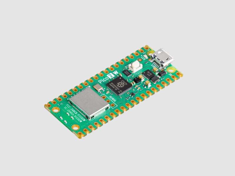
Raspberry Pi Pico 2W is Raspberry Pi Foundation’s update to their popular RP2040-based wireless ico board, now built on RP2350: their new high-performance, secure microcontroller. With a higher core clock speed, double the on-chip SRAM (512KB), double the on-board flash memory (4MB!), more powerf...
molten marten
yup
gray cargo
CircuitPython does not yet support BLE on Pico 2W. It is supported on nRF52840 and various Espressif chips.
molten marten
ah dangit
stone briar
molten marten
ah dangit
can you use micropython?
molten marten
i could but i was specifically looking to use circuitpython for this, its not a huge deal, just one of the side projects to the main project im working on
What wireless communication is available with circuitpython and the pico 2w, if any?
gray cargo
wifi
molten marten
wifi IS supported?
molten marten
Right, not a big deal then, i can probably use my pc/home server as a bridge if i really wanna talk to something bluetooth
depending on the revision of thing i was trying to connect to it might not even be BLE/supported properly anyway so thats not a huge problem

This guy for anyone wondering
stone briar
can a single instance pf ProvideServicesAdvertisement contain multiple services or do i need an instance of ProvideServicesAdvertisement for each service? It looks like it can but im not sure how to format it.
 gray cargo
stone briar
can a single instance pf ProvideServicesAdvertisement contain multiple services ...
gray cargo
stone briar
can a single instance pf ProvideServicesAdvertisement contain multiple services ...
just pass a sequence (e.g., a list) or services in the services argument.
you don't need the other arguments
stone briar
ah ok cheers!
gray cargo
stone briar
ah ok cheers!
wait I am wrong, don't pass a list, just pass multiple arguments, like ProvideServicesAdvertisement(service1, service2, ...)
stone briar
ah a tuple
gray cargo
not a tuple, it takes a variable number of argumetns
stone briar
ohh
gray cargo
self, *services: Service, entry: Optional[ScanEntry] = None
*services is one or more arguments
stone briar
So can I just pass in (HIDService, UARTService, ...) I will try that
gray cargo
stone briar
So can I just pass in (HIDService, UARTService, ...) I will try that
you need to pass instantiations, not class objects:
hid = HIDService()
advertisement = ProvideServicesAdvertisement(hid)
Ok so like this then
 gray cargo
right, try that
note that device_info was not passed and is not used, but you could pass it. That's just a bug
stone briar
gray cargo
note that `device_info` was not passed and is not used, but you _could_ pass it....
aparently Ive forgotten to pass device _info for two+ days now. LOL! I dont use it so I forgot. I may just delete it
gray cargo
some of the examples create it and don't use it
stone briar
yeah I started from an example, didnt even realize it wasnt used
stone briar
This DOES work, *ad = ProvideServicesAdvertisement(hid) * and if ad.complete_name == 'rhf_periph' and HIDService in ad.services:
So I do not think I can detect the UARTService
This does NOT work
*ad = ProvideServicesAdvertisement(hid, uart) * and if ad.complete_name == 'rhf_periph' and HIDService in ad.services:
as well as
*ad = ProvideServicesAdvertisement(uart) * and if ad.complete_name == 'rhf_periph' and UARTService in ad.services:
gray cargo
stone briar
This DOES work, *ad = ProvideServicesAdvertisement(hid) * and if *ad...
does it work if you take away the .complete_name comparison?
stone briar
i will test
stone briar
gray cargo
does it work if you take away the `.complete_name` comparison?
ad = ProvideServicesAdvertisement(hid, uart) and if HIDService in ad.services:
doesnt work
gray cargo
stone briar
ad = ProvideServicesAdvertisement(hid, uart) and if HIDService in ...
Would you be willing to open an issue about that? https://github.com/adafruit/Adafruit_CircuitPython_BLE/issues and include full minimal code for both sides
stone briar
gray cargo
Would you be willing to open an issue about that? <https://github.com/adafruit/A...
am I permitted to attach our discord conversation?
gray cargo
You can just link to it with "Copy Message Link". But make the issue understandable without reference to the discord -- thanks.
stone briar
gray cargo
You can just link to it with "Copy Message Link". But make the issue understanda...
ok https://github.com/adafruit/Adafruit_CircuitPython_BLE/issues/222 maybe this is good
gray cargo
thank you!
dusky shard
I understand that boot.py runs in its own VM but it is able to do some things like board.display.rotation=180 and have it persist later when code.py runs. However it is unable to do sys.path.append('/bin') and have it persist later in REPL or code.py. Is there a mechanism for automatically doing things that persist in REPL ala UNIX .profile or the like.
stone briar
Is there an example of bidirectional UARTService use? Or do I need to make two ble connections between my devices?
gray cargo
stone briar
Is there an example of bidirectional UARTService use? Or do I need to make two b...
https://github.com/adafruit/Adafruit_CircuitPython_BLE/tree/main/examples ble_uart_echo_client.py and ble_uart_echo_test.py are a very simple bidirectional example. You can also test a UART service using the Bluefruit phone app, which has a UART section in it: https://learn.adafruit.com/bluefruit-le-connect/uart-terminal
stone briar
gray cargo
<https://github.com/adafruit/Adafruit_CircuitPython_BLE/tree/main/examples> `ble...
Thanks
Should this exit loop when my peripheral resets and stops communicating? Im trying to write a way to lose connection gracefully. It doesnt seem to see that connection is not connected and fails on the uart.write()
ble = BLERadio()
connection = ble.connect(ad)

I get this instead
 gray cargo
stone briar
Should this exit loop when my peripheral resets and stops communicating? Im tryi...
gray cargo
stone briar
Should this exit loop when my peripheral resets and stops communicating? Im tryi...
Try the example: https://github.com/adafruit/Adafruit_CircuitPython_BLE/blob/main/examples/ble_uart_echo_client.py. I don't know how you are setting up uart
if there's an abrupt disconnection between checking for the connection and trying a uart read/write, then you could get an exception. You want to catch the exception and recover gracefully
stone briar
ok. Im still new to pyton. i didnt think to look up how to try/catch thanks!
stone briar
Ok. here is 'graceful' recovery:
 gray cargo
https://blog.adafruit.com/2026/05/15/circuitpython-10-3-0-alpha-2-released/
Highlights:
- Fix crashes on certain boards with integral displays.
- Adafruit MagTag 2025: improve display quality and support new display variant.
- Add
CIRCUITPY_SDCARD_USBtosettings.tomlto control visibility of a mounted SD card on USB. - Support
floatvalues insettings.toml. - Report USB MSC drives as removable media to the host.
- Update ESP-IDF to v6.0.1.
- Fix
audiomixer.Mixerregressions on SAMx5x. - STM: support
audio.AudioOut, using DAC.
stone briar
is getting this error normal?
AttributeError: 'module' object has no attribute 'time_ns'
i have import time
ruby notch
what's your filename?
though ig it's possible circuitpython is based on a really old python version

 ruby notch
oh strange
stone briar
let me see if i can see which python my chip is using
ruby notch
if I had to guess, it's built on python < 3.7, but if not, that's now beyond my knowledge haha
my guess was you had a file named time.py somewhere clobbering the namespace
gray cargo
stone briar
let me see if i can see which python my chip is using
There is no time.time_ns() in CircuitPython. What's in CircuitPython is a subset of what's in regular Python. There is time.monotonic_ns(). See https://docs.circuitpython.org/en/latest/shared-bindings/time/index.html
 tribal axle
hi i’m new to CP but I know MP pretty well. I have written a bunch of C module ‘accelerators’ for MP to support https://pycoclaw.com and would like to add them to CP, are there any resources for that? Can I just compile CP with them same as i do MP?

PycoClaw — OpenClaw for embedded. Full AI agent on a $5 device.
sick cairn
tribal axle
hi i’m new to CP but I know MP pretty well. I have written a bunch of C module ‘...
There’s an mpy compiler for Python bytecode, but I think C code gets built into the UF2. Static linking
gray cargo
tribal axle
hi i’m new to CP but I know MP pretty well. I have written a bunch of C module ‘...
We don't support that, but there's the latent support from MicroPython which we haven't turned on. Basically, we haven't tried that mechanism and there's likely to be some stumbling block which would need to be debugged. It depends somewhat on how they're structured and what pieces of MicroPython they depend on.
tribal axle
They depend on the os that MP runs on eg esp-idf or Zephyr, using their respective https stacks eg to support wss:// for webrepl-binary https://github.com/jetpax/webrepl
(This is so that Scripto Studio https://scriptostudio.com can communicate securely with the target)
They are structured as regular Cmodules that expose new features eg import webrepl-binary , and there are a few patches added at build time to the 1.28 tree.
When you say “latent support for MP that we havent turned on ” what does that mean for developers?

GitHub
Contribute to jetpax/webrepl development by creating an account on GitHub.
A next-generation IDE for MicroPython. Program embedded devices with natural language. No firmware updates required.
gray cargo
tribal axle
They depend on the os that MP runs on eg esp-idf or Zephyr, using their respecti...
It means there are compile-time switches and values that implement linking in native-C modules. I don't know about Scripto at all.
tribal axle
ok thanks Dan
stone briar
gray cargo
Try the example: <https://github.com/adafruit/Adafruit_CircuitPython_BLE/blob/ma...
so ive used what i learned there to get a challenge/response kind of communication going.
On the central device, i can use except ConnectionError: to detect the peripheral dropping out.
on the peripheral side i am using (time.monotonic_ns() - timeout_start) / 1e9) > timeout_limit to detect when central hasnt sent any data in a while. (Between the two I have a heartbeat signal that fires every half second to keep it alive)
is there a better way to detect connection loss on the peripheral?
gray cargo
so .connected is still true on the peripheral side even though the central has gone away?
stone briar
gray cargo
so `.connected` is still true on the peripheral side even though the central has...
I think so. let me verify before i confirm
It seems so. When I interrupt central's connection. I stop receiving heartbeats and ble.connection is still true

 gray cargo
I think there is no way to tell if the central is really gone or just being slow. So a timeout is ok.
stone briar
gray cargo
I think there is no way to tell if the central is really gone or just being slow...
thank you
gray cargo
I did a lot of work on BLE in the past, but it's very complicated and it takes a while to remember things. So I might be wrong, but I think that makes sense.
stone briar
gray cargo
I did a lot of work on BLE in the past, but it's very complicated and it takes a...
I understand. by the time I had the timer implemented I forgot why i was implementing it 😄 (and that is not very complicated)
gilded dove
gray cargo
yes, doc in <https://docs.circuitpython.org/en/latest/shared-bindings/usb/core/i...
sorry for bringing this up again, I know it's been a while but I am facing some issues.
I made this simple code to test USB host:
import usb.core
import time

# Wait for device to enumerate
print("Waiting for USB device...")
dev = None
while dev is None:
    dev = usb.core.find(idVendor=0x1234, idProduct=0x5678)
    time.sleep(0.5)

dev.set_configuration()
print("Device found:", hex(dev.idVendor), hex(dev.idProduct))

# Bulk write / read
dev.write(0x01, b"Hello from ESP32-S3 host!")
data = bytes(dev.read(0x81, 64, timeout=2000))
print("RX:", data)
but I get an error:
Waiting for USB device...
Traceback (most recent call last):
  File "<stdin>", line 8, in <module>
RuntimeError: No usb host port initialized
I searched the error on google and these docs appeared:
https://docs.circuitpython.org/en/latest/shared-bindings/usb_host/index.html
so I tried importing usb_host and the module was not found
am I missing something? how can a board ship with a module that requires another that is not shipped with it?
gray cargo
gilded dove
sorry for bringing this up again, I know it's been a while but I am facing some ...
I looked but couldn't find it quickly: which board are you using?
 snow storm
Hey everyone! 👋
I'm looking to learn about the Raspberry Pi 5 2GB. Does anyone here have experience with it or can point me to some good learning resources? 🙏
gray cargo
#help-with-linux-sbcs is the channel for that. We have a wrapper library called Blinka for regular Python on that board that allows you to run CircuitPython and talk to hardware: https://learn.adafruit.com/circuitpython-on-raspberrypi-linux.
If you are using Python, see https://learn.adafruit.com/python-virtual-environment-usage-on-raspberry-pi for info about installing libraries.
Otherwise there is a ton of material elsewhere about how to use RPi's. I find the material on the Raspberry Pi websites themselves is often the best when it comes to setup.
gilded dove
gray cargo
I looked but couldn't find it quickly: which board are you using?
T-display-S3-pro-external: ESP32S3
gray cargo
gilded dove
T-display-S3-pro-external: ESP32S3
which CircuitPython build are you using? This is not a board in our board list
gilded dove
gray cargo
which CircuitPython build are you using? This is not a board in our board list
oh, yeah, mb
so there is a build for the T-Display-S3-pro but it displayed a SHELL on the screen all the time, so I switched to a default ESP32-S3
https://circuitpython.org/board/yd_esp32_s3_n16r8/
 sudden kiln
I'm trying out sdcardio / fourwire display / USB mass storage, and while I haven't broken anything (so far) I have noticed that the display gets interrupted partway into refresh when MS is active, and I'm wondering what I could do from user space to get it to not stutter. (at least not as badly) I'm in exploration mode with this one.
gray cargo
sudden kiln
I'm trying out sdcardio / fourwire display / USB mass storage, and while I haven...
It's not that satisfactory, particularly when the display is on the same SPI bus as thd SD card.
If you don't need the USB access, you can turn it off in 10.3.0-alpha.2 by putting CIRCUITPY_SDCARD_USB=false in settings.toml.
but I have also not seen the interruptions you are seeing on various boards with displays, such as PyPortal.
sudden kiln
Nod. I'll probably do that once I'm out of explore mode. And I can share better in a couple days.
molten marten
@gray cargo Would you happen to have that keyboard test code? I forgot to save it
gray cargo
molten marten
<@329766224093249548> Would you happen to have that keyboard test code? I forgo...
I searched for it in discord history: #1504500200293666846 message
molten marten
Ah ofc. that would have worked, thanks i apologise
gray cargo
no problem 🙂
molten marten
Hoping to get the time to turn it into a workable driver sometimes...soonish
this is essentially pretty close allready haha
cosmic swift
Trying to understand how plugging a keyboard INTO an ESP32-S3 board works. I have read CircuitPython natively supports reading input from a USB keyboard meaning you plug in the keyboard and it will work. However the board must have USB Host capabilities and S3s with native USB are not hosts? So you need to add a host board in between? Am I getting that correct?
sick cairn
cosmic swift
Trying to understand how plugging a keyboard INTO an ESP32-S3 board works. I hav...
ESP32 S2 and S3 support OTG. But I think you’ll need to switch to the web workflow for CircuitPython, because a USB port can’t be a host and device at the same instant
cosmic swift
sick cairn
ESP32 S2 and S3 support OTG. But I think you’ll need to switch to the web workfl...
I was trying to set up code on an Reverse TFT and then running it off a lipo so I could plug into the USB port and watch the serial on the TFT. But it was only my first attempt so thought I would ask here for guidance before spending too much time going down the wrong road.
 empty rivet
Hi Boss,
I'm following this jolly page, but where it says 'click the link above to downloaded the latest UF2 file' I get lost because I don't see the download link https://learn.adafruit.com/adafruit-matrixportal-m4/install-circuitpython
Is it to drop it into the matrixboot so it runs something other than the default acceloromteter dot demo?
gray cargo
empty rivet
Hi Boss,
I'm following this jolly page, but where it says 'click the link above ...
hi - link is the box, and yes it's to update circuitpython and will replace any demo on the board (it is probably an Arduino-based demo)
 ancient crown
and once you follow that link, use this button to download the circuitpython firmware UF2 file:
 empty rivet
gray cargo
hi - link is the box, and yes it's to update circuitpython and will replace any ...
empty rivet
gray cargo
hi - link is the box, and yes it's to update circuitpython and will replace any ...
OMG I'm an idiot, thank you so much!
ancient crown
np. if you run into anything else, just ask.
hot bison
cosmic swift
I was trying to set up code on an Reverse TFT and then running it off a lipo so ...
We don't support switching with OTG. The ESPs (except P4) only support host via the external max3421e over SPI
P4 has two native USBs so one is device and one is host
cosmic swift
hot bison
We don't support switching with OTG. The ESPs (except P4) only support host via ...
OK so then I definately would need a MAX3421e based breakout host board between a keyboard and the ESP32-S3 to have the ESP see any keystrokes, correct?
molten marten
Anyone here got an experience writing display drivers? Having some problems with a driver and im unsure if its the settings in the driver or something else entirely
hot bison
cosmic swift
OK so then I definately would need a MAX3421e based breakout host board between ...
Yup, why do you need an s3?
RP2s can do it with PIO on any pins
cosmic swift
hot bison
Yup, why do you need an s3?
I don't. It was just something that I was playing around with for potential future use with one of those USB connected 3-button 1-knob (encoder) mini keyboards that run off a CH552 micro. I generally prefer the ESPs simply for the easy WiFi connection. I do have some RP2040 and RP2350 boards around. By RP2 I assume you mean RP2350 vs RP2040? Or did you mean RP2s as in RP2xxx which covers both? And is it doable in CircuitPython?
cosmic swift
hot bison
it uses a core and pio under the hood
And supported in CP?
cosmic swift
hot bison
yup
Excellent. I will spend some time with one of those boards then. Thank you for the guidance.
gray cargo
@stone briar I'm working on some BLE stuff. Re scan_response. You do not need to supply an explicit scan response. If you omit that argument, start_advertising() creates a scan response (if the original advertisement is not extended), and puts standard stuff in it. From adafruit_ble/__init__.py:
        advertisement_bytes = bytes(advertisement)
        scan_response_bytes = b""
        if not scan_response and len(advertisement_bytes) <= 31:
            scan_response = Advertisement()
            scan_response.complete_name = self.name
            scan_response.tx_power = self.tx_power
        if scan_response:
            scan_response_bytes = bytes(scan_response)
Ok thanks. I was looking through my HCI logs last night and was sorting through the extended advertisement packets and saw some of those. I went to bed in the middle of trying to turn one of my nicenano clones into a sniffer because I got tired of messing with nrf connect 😄 I jump back on that thing in a couple hours
stone briar
gray cargo
you need to pass instantiations, not class objects:
```
hid = HIDService()
adver...
Im looking at advertising/standard.py

I see that it extends an Iterable

When I try to pass in a list, set, or tuple python comlpains that:

I dont understand how to pass an Iterable without using a list, set or tuple
gray cargo
stone briar
When I try to pass in a list, set, or tuple python comlpains that:
The arg is *services, so just pass the multiple services as consecutive arguments. It is a "varargs"
A * in front of an arg name means you can pass multiple arguments, not wrapped up in a list, tuple, etc.
however, there may not be room in the advertisement for all the services you provide. You don't have to include all the possible services in the advertisement. The central will do "discovery" and enumerate all the available services
stone briar
So If I look at this how would I populate this with 2 services and entry?
 stone briar
gray cargo
however, there may not be room in the advertisement for all the services you pro...
stone briar
gray cargo
however, there may not be room in the advertisement for all the services you pro...
I noticed that even if i advertised only hid the uart service still shows up after pairing.
gray cargo
ProvideServicesAdvertisement(hid,uart) or ProvideServicesAdvertisement(*services)
the latter flattens the services list into multiple arguments
it's a python thing 🙂
stone briar
gray cargo
it's a python thing 🙂
yeah its blowing my mind lol
gray cargo
same thing is true in HID: kbd.send(Keycode.A, Keycode.Space, Keycode.X, ...)
stone briar
gray cargo
same thing is true in HID: `kbd.send(Keycode.A, Keycode.Space, Keycode.X, ...)`
nice cheers. I guess ill have to practice it and sleep on it for it to sink in 🙂
gray cargo
>>> def print_all(*args):
...     for arg in args:
...         print(arg)
...
>>> print_all(2)
2
>>> print_all(2, 4)
2
4
>>> print_all(2, 4, 6)
2
4
6
>>>