#help-with-robotics
1 messages · Page 11 of 1
 jolly eagle
 sly sand
just to clarify, what I mean is I don't know how it's done for a specific chip, but it must be possible because if because of some physical constraint you can't place the chip dead center of your robot or it assume it's somewhere else and exactly at the correct lining for your position on earth you should be able to adjust it
 native cipher
Chip doesn't care which side is up.
But the calibration code (if you use any) might need adjusting - it is common that calibration subtracts 1g from z-component of acceleration
sly sand
oof didn't expect something like "Ultra compact high performance e-Compass 3D accelerometer and 3D magnetometer module" in here
I have to find my old robotics course notes/manual to remember how to map the room the car will live in
so i can map it taking into account the accuracy of its sensors
so I can eventually use voronoi
 vocal bear
If I want outdoor service motors, can I expect to pay more? I assume so
sly sand
based on my research with rc hobby you can expect to pay more for water-proof/water-resistant and/or with sensors in them. Usually they will be sculptured to make the water drain a certain way "in" the motor so you can easily drain it but in any case you will have to remove gravel/water/mud etc yourself. But some of them are proprietary and won't work with the correct motor controller
 livid plover
Semi-dumb question. I want to power and control a 5-6v peristaltic pump from a Motor Featherwing, but I’m trying to do it with a battery and as lightweight as possible. Can I connect a LiPo with a 5v step up to said Featherwing? I see examples with 4xAA batteries, but that’s far too heavy for the project I’m working on.
livid plover
livid plover
Semi-dumb question. I want to power and control a 5-6v peristaltic pump from a M...
Also arguable if this is truly robotics, but this felt like the right place to ask!
 lone skiff
livid plover
Semi-dumb question. I want to power and control a 5-6v peristaltic pump from a M...
lone skiff
livid plover
Semi-dumb question. I want to power and control a 5-6v peristaltic pump from a M...
Yep, that should work, as long as the battery and boost converter can supply the current needed by the pump.
livid plover
lone skiff
Yep, that should work, as long as the battery and boost converter can supply the...
Looks like the pump is 500mA. So I think that should be fine!
 pine bramble
sly sand
oof didn't expect something like "Ultra compact high performance e-Compass 3D ac...
pine bramble
sly sand
oof didn't expect something like "Ultra compact high performance e-Compass 3D ac...
Well, the Inertial Measurement Units (IMUs) commonly available nowadays run between US$10 and $30 and are actually quite accurate. Of course, the trickier of them is the magnetometer, but with the Bosch BNO055 and others available, that's also pretty manageable.
sly sand
@pine bramble don't want to pollute #books-and-tutorials but yeah robotics is a good example of what I mean
won't happen without a solid theorical foundation and solid practical foundation
ie: if you don't know about kalman filters and electrical noise in the real-world issues that scale up with size you won't be able to make a great robot
and sure you could search it, unless you don't even know what's it is called so you don't know what to search
and there's a few tricks in knowing the theory as well, like instead of buying 50ohm resistances you could just use 130 ohm ones and minimal ones to change them to other values
surely there's a ton of other tricks I don't know either
anyway just bought practical electronics for inventors and fixing electronics for like 1600 pages total. Should help I guess 😄 That get added to the 1220 pages of art opf electronics I can check whenever I want at the uni
I'm old school so sometimes I like to just lay down and read an actual book like an agathie christie book even if it's about electronics 😄
 weary stump
Thought you guys might enjoy this tri-directional soft robot I'm making for work! It can curl left right and up, this is showing the right side curling action.
vocal bear
Does this exist? A pulley with two separated, but mechanically linked, sets of teeth?
 pine bramble
Have you looked at either ServoCity (Imperial measurement) or goBILDA (metric) before? You could rather easily create that using their components. (I'm not associated with either company, just a satistied customer)
vocal bear
SDP/SI was my first stop, didn't find anything so I figured I'd ask the experts
I'm a happy SDP/SI customer
pine bramble
goBILDA is a modern build system designed for engineers, artists, students and makers. It's metric, lightweight, and has an ever-growing library of parts
vocal bear
How are pulleys like that mounted? I was just at that page lol
pine bramble
vocal bear
How are pulleys like that mounted? I was just at that page lol
Onto a hub. There are many kinds of hubs, depending on the kind of shaft you want. There's also spacers. Everything in their line works on the same spacing so it's basically like Lego.
vocal bear
Is the hub using a set screw?
pine bramble
vocal bear
Is the hub using a set screw?
Some do.
vocal bear
Others?
pine bramble
I'll let you browse: https://www.gobilda.com/hubs/
goBILDA is a modern build system designed for engineers, artists, students and makers. It's metric, lightweight, and has an ever-growing library of parts
"Hubs play the critical role of transferring motion from a shaft to the next component in the drivetrain whether that be a gear, pulley, wheel or arm. The different styles each have their strong points from brute holding force to attachments options to weight savings."
vocal bear
Interesting
pine bramble
I've used several different ones, currently the Hyper hubs for my Mars rover's wheels.
The Sonic hubs are good for high-speed applications because they're balanced.
et cetera
vocal bear
I want to make 6 small things spin on a large piece of plywood so I'm just evaluating options
pine bramble
vocal bear
I want to make 6 small things spin on a large piece of plywood so I'm just evalu...
I usually head down to the hardware store and browse around for ideas...
vocal bear
Yeah I'm gonna do at least one thing with all hardware store stuff if I can.
I want to make a ( https://en.m.wikipedia.org/wiki/Jumping_jack_(toy) ) out of plywood, pulleys, and rope.
The jumping jack is a jointed, flat wooden figure, a cross between a puppet and a paper doll. The figure's joints are connected to a pull string, which causes the arms and legs move up and down when the string is pulled and released.
Gosh that link isn't posting right
The jumping jack is a jointed, flat wooden figure, a cross between a puppet and a paper doll. The figure's joints are connected to a pull string, which causes the arms and legs move up and down when the string is pulled and released.
It's the parenthesis
Pitch diameter is the relevant metric when considering pulley reduction ratios, correct?
 primal shell
Yes
vocal bear
Thx
vocal bear
Is your average brushed motor more weather resistant than other types?
primal shell
Motor type matters (much) less than motor enclosure type. A brushed motor has mechanical commutators which may be messed up by exposure to weather, while a brushless motor is simpler, just coils and magnets, and some forms have no sliding contacts at all.
native cipher
wouldn't say that any typical motor - brushed or brushless - is weather resistant unless it is placed in waterproof enclosure
primal shell
You can think of a brushless motor as an "electronically commutated motor"
vocal bear
I'll have to source motors from a place that sells enclosures then
vocal bear
Pulley question: do you have to take care in choosing the right number of teeth for two pulleys in order for the belt to work?
lone skiff
vocal bear
Pulley question: do you have to take care in choosing the right number of teeth ...
This question isn't completely clear to me. You definitely want to make sure about the tooth spacing, but the number of teeth will just affect how fast the pulley spins for a given belt speed, or vice versa... so it depends on whether you care about that.
vocal bear
Hm
I must be misunderstanding something
I guess I'll ask a different question. Is there a problem if your pulley has fewer teeth per inch around the circumference of it than your belt has?
lone skiff
Short answer: yes. It's likely that the belt will slip irregularly between teeth and wear badly.
vocal bear
Thanks. Why does misumi sell gears under a specific belt type by number of teeth instead of by diameter?
And just have the right number of teeth for a given diameter they sell? Seems weird
lone skiff
Generally people don't really care about the diameter, but they do care about how many revolutions a given length of belt translates to.
vocal bear
Ah ok
native cipher
pitch (teeth per inch) of belt and pulley must match perfectly.
It is indeed common to list pulleys by # of teeth rather than diameter - since one of them determines the other, it doesn't really matter
in addition, # of teeth on two pulleys, length of belt, and center-to-center distance between pulleys must also be consistent. There are many online calculators that, given pulley parameters and belt lenght compute for you center-to-center distance
vocal bear
Thanks.
native cipher
or vice versa, given pulley info and c-to-c distance, compute required belt length
vocal bear
Yeah I'm gonna need some custom belts in the future so I have to re learn what I forgot about pulleys
native cipher
but also, if you can't get the right belt length, there are such things as belt tensioners
vocal bear
Yeah I'll be using a tensioner regardless
primal shell
The tooth counts are very useful for calculating speed ratios, which is why they're popular
vocal bear
That makes all the sense, I was thinking about it wrong.
 crystal raven
Hi guys! I need some help with this piece of code. Basically im trying to control a linear stage (with a stepper motor) using a rotary encoder. Everything works but its a bit too slow right now as even with no microstepping, the rotary encoder needs to go through 200 clicks for my stepper to move 1 revolution. Im trying to see how can i get the code to make the stepper rotate half a revolution (100 steps) every rotary click of the encoder. Any help is greatly appreciated!! Thanks in advance! I've put the code on pastebin here
https://pastebin.com/u5avzkRH
Pastebin
Pastebin.com is the number one paste tool since 2002. Pastebin is a website where you can store text online for a set period of time.
 vagrant thunder
crystal raven
Hi guys! I need some help with this piece of code. Basically im trying to contro...
vagrant thunder
crystal raven
Hi guys! I need some help with this piece of code. Basically im trying to contro...
There are a number of ways to accomplish this, but the easiest way to do this is probably to change the rotate() function to increment or decrement in multiples of 100. For instance, the line RotateCounter++; would become RotateCounter+=100;
crystal raven
vagrant thunder
There are a number of ways to accomplish this, but the easiest way to do this is...
holy crap that one simple change worked thanks so much!!! Could i trouble you to explain what happened though? I tried RotateCounter+100; but it didnt give the expected outcome. Apologies im still a very early learner!
vagrant thunder
RotateCounter+100; is a simple expression that doesn't actually assign the value back to RotateCounter. If you had used RotateCounter=RotateCounter+100; you would have had the same result as the code I suggested.
crystal raven
vagrant thunder
`RotateCounter+100;` is a simple expression that doesn't actually assign the val...
Ah gotcha i see where i went wrong. Thanks for the help!! Learnt something new today
vagrant thunder
It's also worth mentioning that steppers are not the fastest motors, as they are typically used for fine-precision movement. If you want something that moves faster, you can trade some precision for speed with a BLDC motor instead.
crystal raven
vagrant thunder
It's also worth mentioning that steppers are not the fastest motors, as they are...
Got it thanks! Im making a simple organic sample translation table so i need the fine movement haha
crystal raven
vagrant thunder
It's also worth mentioning that steppers are not the fastest motors, as they are...
 vocal bear
How would folks go about enclosing a motor to protect it from rain/dew/etc?
Brushed DC
If that changes anything
native cipher
how large?
vocal bear
Undetermined
Not huge
Mechanical loads are pretty light
Let me get a pic of what I was considering
Can't get a good pic, dark location. Motor can is ~1.43" diameter and ~2.15" long with a largish gear box
native cipher
obvious choice would be putting it in some enclosure, which are easy to find, and then use a bearing where the motor shaft goes through the wall. The bearings are not waterproof, but shoudl be good enough to protect from dew/moisture/rain (unless it is facing straight up)
if this is not good enough, google "shaft seal"
I've seen it discussed, but never used myslef
what is the shaft diameter?
4mm? or 6mm?
anyway, bearings are readily available, e.g. https://www.servocity.com/4mm-id-x-12mm-od-flanged-ball-bearing-2-pack/
vocal bear
I can basically choose any motor I want, within reason. I'll look into shaft seals
native cipher
servocity and pololu have large range of motors to choose from
vocal bear
Thanks
I'm probably gonna try to use as many misumi products as I can as they are nice.
vocal bear
I'm shopping for BLDCs and controllers. Would I need to write my own driver software for something like this? https://www.anaheimautomation.com/products/brushless/brushless-driver-controller-item.php?sID=811&serID=31&pt=i&tID=999&cID=23
primal shell
Nah, it just takes a voltage for speed and a logic level for direction
vocal bear
interesting. I'm perusing lots of their products now for a future installation
 ebon arrow
Does anyone know if ODRIVE is open source?
sly sand
ebon arrow
Does anyone know if ODRIVE is open source?
???
 ebon arrow
Yea I saw that lol and was going to edit my own question as solved
sly sand
I like open-source things when they respect the specs (and aren't random clones that don't respect the specs) someone suuggested an opentx remote for my project
Which even if it's pricier than usual r/c for cars at least it's not proprietary and I don't have to use all their specific ESC amd specific brushless motors
plus opentx can work for car as well as drones or any type of robot
ebon arrow
Yea I am looking at it as a reference for my PCB layout. Cant really figure out how to lay out the high amperage stuff
sly sand
while the cars ones with have an auto-center thing you can't disable
ebon arrow
Oddly enough using DFN style FETS saved me a ton of space and are more efficient.
sly sand
I'm a beginner atm so you lost me a bit already. I know DFN is a chip package but I can't weld one for use on a breadboard for sure
 sly sand
my level is past tutorial, so I got a non-toy robot tank kit (zuma 32u4) but I wouldn't be able to make a robot from scratch or even a PCB yet
ebon arrow
the resistors on the bottom are the usual 1206 to give you an idea
ebon arrow
sly sand
my level is past tutorial, so I got a non-toy robot tank kit (zuma 32u4) but I w...
You'll get there 🙂
sly sand
Like atm I know how to electrically add sensors to my robot but have no idea how to actually put them on a plate and add it to my robot and screw it in
ie: I'm worse than beginner at making stuff with my hands
ebon arrow
that requires a bit of mechanical finesse. Im not sure how to teach that part. But Ive been in and out of machine shops and have helped build machines as well
sly sand
And I'd like to make an enclosure for it too and affix a ESD neutral pen inside it to run the test suite because the psuhbttons are really small and I'm always scared of getting static to the PCB when using them
ebon arrow
I dont think you would have to worry about ESD that much.
Also if you want to tickle your mechanical fancy ,Blondihacks on YT is pretty good
https://www.youtube.com/c/Blondihacks

YouTube
The Blondihacks Channel features projects and educational videos by Quinn Dunki, covering topics ranging from electronics, home-brew computing, machine shop work, welding/fabrication, 3D printing, and more. Many are companion videos to full project write-ups, which you can find at http://www.blondihacks.com
Only some of my content is available ...
sly sand
robot kit would maybe seems basics to others, but it doesn't have hand holding or cheapest sensors unlike tutorial ones
it's basically one with a datasheet and a datasheet for each parts, and "good luck"
ebon arrow
You want something like an arduino then but for robots?
sly sand
ie: here are the specs for the proximity sensors, how to test them, and the library and the library docs and a small example that doesn't involve navigation, using motors to avoid obstabcles so good luck
no I'm saying I got exactly what I wanted
ebon arrow
Ohh
sly sand
something that wasn't for a total newbie but the step above
just a little bit out of the comfort zone and without the cheapest sensors
ebon arrow
Next step now would be to make your own 😛 Once your comfortable ofc
Or just keep modifying/adding/modding until you cant recognize the thing anymore.
sly sand
pic of the suspect

yeah i'm more of a modder than a maker
I purchased it assembly because I can't even solder yet
ebon arrow
sly sand
pic of the suspect
Oh Ive seen that. Cool little thing.
sly sand
Ichiro.Furusato recommend it to me, took a robotics course 12 years ago at the university but it was theory heavy we didn't build anything but had to find the formula for sensors noise from measurements, do kalman filters etc
and I wanted to start with do something real but couldn't break the wall of complexity
so they suggested it and how it will keep me busy for a long time making a shell for it, adding a camera, navigation, mapping out the environment, handling mobile obstacles etc...
ebon arrow
Have you looked into Udemy?
sly sand
nah I have a good theorical base and books on electronics/robotics, just need hard experience
udemy is a bit weird as well, their courses are always supposedlyt worth 3000$ but on special for 10$
I'm running basic tests atm to see if the robot works, but after that I'm hoping to find an algorithm for voronoi diagrams based navigation that I can use for mapping my test room
ie: something like https://www.cs.columbia.edu/~pblaer/projects/path_planner/
ebon arrow
Interesting. Best of luck to you. That stuff is a bit above me ATM 🙂
sly sand
Basically I'm trying atm to figure out how to use the sensors so that when I turn the motor switch on it doesn't crash into a wall and waste my 150$ 😦
ebon arrow
and yea UDEMY is weird. They only use either STM or TI micros. Nothing against them but I want to learn PICs more
Bumpers. Literally get the pool foam things and cut those up
sly sand
was planning atm to use one of my food delivery box because it has 2 sheets of cardboard over a hex like pattern between them but that won't work if the robot roll the box into a wall 😄
native cipher
Are you using a Zumo bot? it should survive hitting the wall
sly sand
yeah, and it can goes at 18kph instead of 25kph because I'm using NiMH batteries so it has 4.8V instead of 6
native cipher
I'd say 18 should be sufficient - unless you try to run races
sly sand
it has an unwieldy feature that basically it won't run motors unless it's connected with batteries and you put the tiny switch on. But I'll have to touch the threads to do that so I'll make the program so it give me a good delay between opening the switch and the motors starting up
ebon arrow
Or you can add a softstart
sly sand
And I can't find info on the sensors normal distribution noise values so i'll need to test that
ebon arrow
have it start at 0 and ramp up to a desired level
sly sand
to figure out how "thick" I have to program my walls taking account accuracy of the sensors when mapping
ie: if the sensors follow a N(10mm, 4mm) normal law for instances I'd program my walls to be 20mm thick to make sure I avoid issues
native cipher
which sensors? the IR distance ones?
sly sand
well all of them, not going to trust just one sensors for measurement
with the mapping I can also use the odometer to double-check
probably going to have it slow down as well between 40mm away from the wall and 0mm
sly sand
It has a sort of snow plow in front so probably can resist some damage but I'd rather be extra careful as my skill level rises up
I meant 40cm, 10 times wall thickness as I learned in my robotics course sorry
native cipher
it can take quite a bit of direct hits. Check YouTube for videos of Zumo robot sumo competitions
I had them used by kids in robotics classes, so they were occasionally dropped on the floor and mostly survived
the LCD screen is finicky, everything else is quite sturdy
sly sand
they sent me the version with 1968 lcd screen :(((
instead of oled and can't exchange it, they don't even sell the oled version...
native cipher
they just released OLED version - it is brand new
But that was one of the things that I wanted to change when I created my own modification:
http://yozh.rtfd.org
sly sand
It probably can be replaced one day I guess
it's not that important, just testing robotshop service quality I guess
I mean no matter how nice it is, can't really read it when the robot is moving
and a pi connected with "magic" (don't know how yet) to it displaying on a 1080p TV with hdmi cable on windows 10 IoT will probably be much nicer
Which i'll need one day because I really want to have a camera one-day in there
that would possibily involve using a shield/an arduino and mount it somehow because I doubt the chip can handle a camera or the pins
and the only way I see it possible physically atm is by adding a wheeled trailer on it (possibly from a cheap toy) with a hook kinda like a SUV does to carry the arduino and the batteries for it
And like Ichiro said, there is a capability scale for robotics. First step is to actually understand the sensors and how to use them and understand the example code/library
Then actually move it, then move it finely using the encoders, possibily having it do tank style movement (ie: motors only on one side)
probably would have been cheaper though to use the same sensors and mount them on a cat with wearables 😄
But I'm allergic to cats so...
I'm using the proximity sensors example program and the sensors seems to be fast response time and seems sensitive
vocal bear
can anyone recommend a good brushed DC motor company? Preferably that sells motors with encoders attached as well as control boxes? I'm hoping to find a solution that's cheaper than BLDC. I don't need really fine control.
pine bramble
vocal bear
can anyone recommend a good brushed DC motor company? Preferably that sells moto...
You might try Pololu, who sells an assortment of sizes, many with encoders.
vocal bear
hmm ok thanks. I thought I checked there. I was hoping for an industrial supplier like the onesI found for brushless motors. They sell the motor and a control box that can set speed with just a PWM signal.
I don't really have the time to design and tune a PID.
pine bramble
There's a couple of German companies that sell industrial DC motors but with encoders their motors cost many hundreds of dollars each.
vocal bear
Dang. Well I'll have to figure something out.
Thx
I'm really after IP rated motors, which is why brushless was attractive. But brushless motors with encoders and control boxes are necessarily expensive
How would you go about finding a control box for something like this?
https://www.pololu.com/product-info-merged/4886

This gearmotor consists of a low-power, 12 V brushed DC motor combined with a 74.83:1 metal spur gearbox, and it has an integrated 48 CPR quadrature encoder on the motor shaft, which provides 3591.84 counts per revolution of the gearbox’s output shaft. The gearmotor is cylindrical, with a diameter just under 25 mm, and the D-shaped output shaft...
and does 74.83:1 mean the output shaft turns 74.83 revs per rev of the motor?
 earnest totem
I think it's the opposite, typically you would want to gear a motor down. It'd be 1 output shaft turn per 74.83 revs of the motor
vocal bear
Ah ok
earnest totem
For a gearbox (i believe it's basically convention) the first number in the ratio is the input and the second number is the output
pine bramble
The higher the gear ratio the slower the output shaft turns, and the more torque you gain.
vocal bear
Ok I don't need very fast motion but torque is useful
earnest totem
earnest totem
I think it's the opposite, typically you would want to gear a motor down. It'd b...
I should say in most applications you want to gear an electric motor down. They can often turn very fast with low torque, so applying a reduction gives you a slower rpm but better torque
pine bramble
I think most people building robots end up with a robot that moves too fast at top speed so they only end up using it to 20-50% power. So it's probably better to have a very high torque, low-speed robot. My last purchase was for 52rpm motors, with a stall torque of 292 oz-in. I.e., I was buying for torque, not top speed. E.g., these are smaller 22mm diameter motors:
https://www.servocity.com/52-rpm-premium-planetary-gear-motor-w-encoder/

You'll also want to consider whether you want plain (hopefully bronze) bearings or ball bearings on the output shaft. If the motor's shaft is going to encounter any shock, such as if it's connected directly to an outdoor robot's wheels, you'll want ball bearings. (This is of course if your application is robotics...)
vocal bear
Ah I'm not actually building a robot, this is just the most appropriate channel to find folks who know about motor control. I have to build a number of static devices that have motion incorporated into them. The motor itself will not travel anywhere, just hang out and spin back and forth.
I only have about 9 months to build and design a bunch of stuff so I'm hoping to find motor controllers that I can just send a signal to. Essentially creating a servo
pine bramble
vocal bear
I only have about 9 months to build and design a bunch of stuff so I'm hoping to...
Why not simply use a large servo and servo controller? They come in all sizes.
vocal bear
That's an idea I've considered, I just haven't looked into it yet to see if it's suitable. Hobby servos I've worked with were not suitable
pine bramble
Servos come in very very high torque versions. Probably a lot easier. As you may know, a PID controller can control for either velocity or position. You'd have to provide encoders and a PID controller for position control, or come up with some other way to sense absolute position. That's trickier than just buying a servo that does that already. Other option might be a stepper and stepper controller, which likewise come in all sizes.
vocal bear
I'm planning on using a stepper for a rack and pinion design I'm considering. I don't need very high torque, it's just that torque is more desirable than high speed
but I'll need to find continuous rotation servos.
pine bramble
Any idea what your torque requirements are?
vocal bear
No I haven't started modeling yet. That's my first step after this project and the next one are complete.
pine bramble
Here's a selection from ServoCity, though there are much larger ones available too.
https://www.servocity.com/continuous-rotation-servos/
Welcome to ServoCity where you can get the parts you need to bring your ideas to life! From servos to switches, from actuators to Actobotics, we work hard to bring you the best components backed by unparalleled technical support
Of course, the larger the servo the more expensive the servo controller.
pine bramble
Sure, so long as the MCU can support whatever requirements there are in the driver. If it’s signal level only then no problem.
vocal bear
Cool thanks.
vocal bear
@pine bramble how would you go about sourcing enclosures and shafts for servos like those?
hmm finding waterproof continuous rotation servos is gonna be difficult.
primal shell
You might have to add a waterproof enclosure around it, with a bushing, packing box, or one of the more exotic hermetic rotary seals with conical rollers driving each other through a deformable sheet
vocal bear
that's what I was thinking re: enclosures. How do you add a shaft though?
primal shell
Add a shaft? Huh?
vocal bear
to the output of the servo
primal shell
That's the bushing, packing box, or other sealing mechanism that transmits rotary motion that I mentioned.
vocal bear
ah ok
thx
dang they have plenty of continuous rotation servos at goBilda but they are sold out of the re-programmer required to put them in continuous mode
primal shell
That's inconvenient. I wonder how hard it is to roll your own.
vocal bear
that was my thought. I don't think they'd just give out the information required but I can email them
I'd be happy to pay double what it costs to get one, there must be a way to put that desire out into the web
hmmmm, this is suspiciously similar to the one from goBilda...https://www.studica.com/en/smart-robot-servo-programmer

Studica, Inc.
The Studica@Smart Robot Servo Programmer is used for programming the Studica Multi-Model Smart Servo Motor@and for testing other standard Servos.@Use it to program the Studica Servo to switch between@continuous mode, standard mode, or any custom angular mode.@ Can be powered with@
@
Specifications:
Requires 6 Volt battery pack with TJC8 connec...
primal shell
I might just use a brushless motor along with an ESC, gearbox, and encoder instead of going the servo route, but there are lots of approaches.
vocal bear
yeah I was trying to keep costs and complexity down as much as possible.
Servos are very attractive because I can theoretically control them with one pin
Brushless motors are nice if you can get IP rated ones, but that costs hundreds of dollars per
primal shell
You can control an ESC with one pin as well. As we already discussed, it might make sense to put a non IP rated motor in an IP rated enclosure.
You might find you run into a tradeoff between cost and complexity. That's a really common one in engineering.
I often find the cheapest, most flexible, and easiest to shop for approach is to build the functionality I'm looking for out of individual common units instead of trying to find a ready-built specialty unit that includes all of my desired features.
This goes double when I find the requirements change, and I can swap out one or two cheap modules instead of replacing the whole shebang with a different one.
vocal bear
hmm interesting thanks. I was leaning towards enclosed motors that themselves have some ingress protection, for extra safety. I'll have to see if I can find the right combination of ESC, encoder, motor, and enclosure.
a bipolar motor is AC, correct?
primal shell
I'm not sure what you mean there. I've seen "bipolar" in reference to stepper motors, but not elsewhere.
vocal bear
Order today, ships today. 1208 – Bipolar Stepper Motor Hybrid Frame Size 14 200.0 Step 500 mA 10VDC from Pololu Corporation. Pricing and Availability on millions of electronic components from Digi-Key Electronics.
oh my gosh, that's quite a link
ah it's a stepper
native cipher
vocal bear
dang they have plenty of continuous rotation servos at goBilda but they are sold...
as an alternative, you can get this one: https://www.revrobotics.com/rev-41-1097/

REV Robotics
REV Robotics designs, builds and manufactures robotics parts and components used by students for learning about science, technology, engineering, and math (STEM). Our parts are commonly used within the FIRST Robotics Competition and the FIRST Tech Challenge.
as far as i know, both gobilda and rev servos are based on the same fentech servo
and rev reprogrammer is in stock
vocal bear
ooh that's nice. Yeah having a hard time deciding between servo vs BLDC + ESC/Encoder. I like the second one more from an engineering perspective but a servo is probably all I need, presuming it can go fast enough
native cipher
i have no experience with bldc, unfortunately
but id also suggest you to check dynamixel motors
vocal bear
I started a hobby BLDC motor board but got distracted with work and other projects
native cipher

ROBOTIS
ROBOTIS is a global robot solutions provider and one of the leading manufacturers of robotic hardware. ROBOTIS is the exclusive producer of the DYNAMIXEL brand of all-in-one smart servos. We specialize in the manufacture of robotic hardware and full robot platforms for use in professional settings, all fields of study, and industry. ROBOTIS als...
vocal bear
thanks. Servos honestly seem really attractive. Just have to find the right enclosure
native cipher
it is similar to servo, but has more features
vocal bear
checking out dynamixel motors now
I assume the shown horn can be removed?
Hmm I don't see a bushing/set screw available for these. I'll keep digging.
native cipher
main advantage of dynamixel is that it offers speed and position feedback - which you do not get from a regular servo. Not sure if it is important for you
vocal bear
ooh that's good toknow
I honestly don't foresee me needing much in the way of torque so speed and position control is really nice to have
how would you attach a shaft to one of these, @native cipher ? I don't see a bushing in their product list
primal shell
Mechaduino is another similar sort of offering
vocal bear
hmm, can the dynamixel be controlled from any random controller or do you need their control board? I need a number of these and they aren't exactly close to each other.
native cipher
you need a control board communicating with dynamixel by uart
there are 3rd party boards
vocal bear
Could I roll my own board? Let me see if there are UART multiplexers
hm, may have to stick with servos. Lots of UART seems complicated. And buying a control board for each is cost-prohibitive.
native cipher

Instructables
How to Drive Dynamixel AX-12A Servos (with a RaspberryPi): I decided to use some Dynamixel AX-12A motors for a project, and ended up having to code a library for them, so I figured I would share what I learned.Despite being a bit more expensive, this motor has a couple of advantages over the more commonly f…
but indeed regular servos are much easier
vocal bear
yeah I have 8-9 months to design two large systems by myself so I'm trying to get it as simple as I can.
Thanks for letting me know about that brand though, @native cipher. Really impressive stuff they've got there.
pine bramble
vocal bear
that's what I was thinking re: enclosures. How do you add a shaft though?
I would recommend checking out the radio control boat and radio control submarine communities. They have this sussed.
vocal bear
Nice thanks
vocal bear
does all the mechanical energy of say a fan blade spinning get converted into heat in the bearings when you pull the plug from the fan?
I guess some of it would go to mechanical energy in the motion of the air, no?
native cipher
I think that most goes to heat. Motion of air is very little energy compared to heat.
lone skiff
Some of it will probably end up as heat in the circuitry too, since a motor is also a generator, creating currents in the motor coils, etc.
vocal bear
ahhh ok thanks. I was just trying to think about energy during my break.
 mint dust
I spent the past two days nonstop working on this quadruped leg... And only after assembling realized that both servos need to work in tandem to actuate just one axis (I was planning on it being one servo per axis). I'm worried that this will be very complicated to write inverse kinematics for. I'm looking for some advice on that- I suppose first I should determine how to actuate one axis at a time, abstract that method and then move onto calculating joint angles as if it were one servo per axis?


For example moving the left servo, with the right servo being still, results in a nearly straight line motion of the foot upward/downward. Which sounds convenient, but I feel like it'd get complex trying to do the rest..
primal shell
The kinematics aren't that hard, really. This article has some useful description. https://www.elektormagazine.com/magazine/elektor-201701/40130

Elektor
This nifty gadget built around an Arduino Uno uses some servos and a pantograph mechanism to write the time in a sand bed. After a configurable time interval the sand is smoothed out by a pair of vibration motors and the cycle starts over again. Along with the automatic time mode, the clock software has a command mode which allows you to control...
mint dust
that looks like a good resource, thank you ill save it
vocal bear
Does a continuous rotation servo remember where its 0 point/ start point is between power cycles?
pine bramble
Perhaps someone can correct me if I’m wrong but I believe a continuous rotation servo always reflects its input phase but has no “memory”
vocal bear
darn ok.
So I could use microcontroller memory like nvm in circuitpython to store the last state?
what do you mean by "reflects its input phase"? Like it communicates back to whatever is controlling it?
native cipher
as far as I understand, usual hobby CR servo has no "0 point". You give it pwm signal, it starts rotating clockwise or ccw.
and there is no feedback of any form either.
unless you use something more sophisticated than regular hobby servo
vocal bear
hmmm
well that complicates things.
Or means I have to go with linkages if I want back and forth motion, which is OK I guess.
pine bramble
vocal bear
what do you mean by "reflects its input phase"? Like it communicates back to wha...
Just as @native cipher indicated, the PWM signal controls the servo but there’s no feedback or notion of a position
vocal bear
yeah makes sense.
I may just use brushed DC motors with sufficiently geared down speed and just drive crank rockers/crank sliders
pine bramble
A PID controller can control for either velocity or position, if that’s any help
vocal bear
yeah if I had more time I'd do PID with an indexed encoder to have a 0 position but unfortunately I don't have much time
linkages will have to do
pine bramble
What about subminiature lever/limit switches?
pine bramble
Or an optical interrupter, since a software mistake with lever switches would potentially damage something (shear off a pin or damage a switch, etc.)
A disk with a hole in it would gain you a zero point
vocal bear
yeah I could just travel in one direction until I reach the hole and then start the motion. I'll have to ponder a bit. Linkages might be slightly more robust since this is outside and there would be fewer parts susceptible to water damage
thx
 lone fiber
Hi Guys, I want to use the Feature wing to drive the stepper motors, for some reason it just go back and forth instead of spinning 360 degree.
here is the code: ```import time
import board
from adafruit_motorkit import MotorKit
from adafruit_motor import stepper
kit = MotorKit(i2c=board.I2C())
for i in range(100):
kit.stepper1.onestep()
time.sleep(0.05)
kit.stepper1.release()```
 runic dust
Or double post it in another channel, that works too.
And this isn't really a robotics question, it's a CircuitPython question.
So, how about we go back there. 🙂
lone fiber
oh ok...
 manic depot
Looks like the coils are connected wrongly. You may want too look at the motor specs and the doc of your motor driver
 lilac wing
So I am planning to use marlin as a robot controller, and I was trying to find a code that splits gcode movements into smaller movements let say 2 gcode lines into 10 gcode lines, someone that know a library like that?
 deep oyster
Hello! Anyone here interested in getting paid to tutor me on some Arduino code organization for my RF controlled auxiliary servo headlamps for my car? Thanks! @winter dawnblackrobotics IG
 vocal bear
deep oyster
Hello! Anyone here interested in getting paid to tutor me on some Arduino code o...
vocal bear
deep oyster
Hello! Anyone here interested in getting paid to tutor me on some Arduino code o...
Check out the adafruit jobs board
deep oyster
vocal bear
Check out the adafruit jobs board
thank you
 restive pike
lilac wing
So I am planning to use marlin as a robot controller, and I was trying to find a...
restive pike
lilac wing
So I am planning to use marlin as a robot controller, and I was trying to find a...
As someone only familiar with gcode for machine tools, what's the goal for this?
lilac wing
restive pike
As someone only familiar with gcode for machine tools, what's the goal for this?
I am making a timelapse head for my camera, If I use a custom pendant to set point A and point B, I was wondering if there is already a library that takes those points and split them into 300 movements so I can move, take a picture, move, take another one and so on. I find some autoleveling algorithms and trying to use those as a start point
autoleveling seems to do something similar take a line movement and split the line into 10 points just to adjust z axis in every part of the mapping
I don't need the z correction, so I will enter a M instruction to take a picture
restive pike
If that doesn't work for some reason, maybe just a G91 incremental movement and the M code looped for the required number of movements?
Looks like Marlin should support that with M808
 spring prism
Hey there, I'm still very new to working with circuitry. I saw the Adafruit CRICKIT and it looks like it would make connencting things to a Circuit Playground Express a bit easier. Does it also work for the Circuit Playground BlueFruit, or is the differences too great? From the pics, the connections appear to be the same, but I thought I'd double check.

Sometimes we wonder if robotics engineers ever watch movies. If they did, they'd know that making robots into slaves always ends up in a robot rebellion. Why even go down that path? Here ...
 cursive helm
spring prism
Hey there, I'm still very new to working with circuitry. I saw the Adafruit CRIC...
cursive helm
spring prism
Hey there, I'm still very new to working with circuitry. I saw the Adafruit CRIC...
It works well with the CircuitPlayground Bluefruit as well. Here is one example https://learn.adafruit.com/bluetooth-turtle-bot-with-circuitpython-and-crickit
 zinc stream
Hey everyone, I got my first Arduino Uno for Christmas, and my parents found my old REV cars while they were cleaning.
Those robot cars made by WowWee that are connected to an app?
Well, I was curious, and I wanted to test out my new screwdriver set, so I took the top cover of one of my two cars apart.
by doing that, I found an unpopulated UART header on the board, with holes just large enough to fit 4 Dupont wires into.
And so I did a thing

I modded the wiring layout inside the unit to get wires coming from the UART header to come out the hole where the LED normally is. The LED is still there, but there’s a cover missing on this car. I also figured out that by plugging my Arduino into this header, the Arduino can send partial power to the car while it’s plugged into my computer, without the power switch turned on, and when the power switch on the car is turned on, the car can almost fully power the Arduino without any USB or DC cables plugged into it at all.
So my main question is, Can anyone help me hack this REV car further? I wanted to possibly get a serial console running from the car to the Arduino via UART
I wired the ground pin of the UART connection to get its power from elsewhere on the board, as it creates a more secure connection that doesn’t come loose
I couldn’t really find much documentation on anyone hacking this car, but maybe I just don’t know what to look up on Google
Also, I don’t own a soldering iron, in case that helps or does the opposite of help
zinc stream
If anyone could please help me with this, you might wanna create a thread if it’s needed
native cipher
zinc stream
Hey everyone, I got my first Arduino Uno for Christmas, and my parents found my ...
I have seen some projects like that, but never done it myself.
I can try and find them.
All these interfaces on RC cars like that are commonly undocumented - they were never intended to be exposed to the user. Good thing is, many of these cars use the same basic design, just rebrand it
zinc stream
Really? That’s good to hear
Well what’s the point of having a UART output on an RC car
Especially an app enabled one
native cipher

Instructables
Hacking a RC Car With Arduino and Android: Whenever I walk into a toy store and see remote control cars in the window, I think to take take them home, maybe because as a kid I adored this kind of toy, but for lack of options and money (they were much more expensive than today), I had not. To…
zinc stream
It’s less generic Than you’d think
Robotic enhanced vehicles built for battle.
But I’ll keep that one in mind
 nimble falcon
I am having a massive brain fart with trying to hook up 12 SG90 servos to a PCA9685 from (First an ESP32, but also trying with Arduino Uno). I have a 6V power supply (AA 900mHa) plugged into the PCA and I've tested all servo's individually, but for some dang problem I can not get the Servo's to move/position at all with the PCA. I even replaced my PCA9685 worrying the other got fried some how.
Not sure if this is a good place to reach out.. Have been getting frustrated with this. 😦
lone skiff
The usual advice would be to start simple... drop it down to one servo, and use some PCA9685 example code to try to do some simple moves with it, to verify your general setup.
nimble falcon
Oh I have.. 😦 I went with different servos on different channels with just an easy snippet and I can't get the servo to move as long as it's in the PCA. I double checked the address for the i2c and that shows correct. I'm pretty new to i2c and a little confused if I need to add a pullup resistor on the i2c data and clock lines to 3v3 as well? 😐
lone skiff
nimble falcon
Oh I have.. 😦 I went with different servos on different channels with just an ...
Pullups are required in general for I2C, but the Adafruit board should have them on it already. If you're not confident in the I2C connection, though, it would be a good move to try running one of the I2C scanner example codes to see whether the address shows up on the bus.
 gentle totem
Hello, I have an Adafruit Motor FeatherWing and I want to control it over I2C from a Pi Pico with MicroPython.
Where can I find a documentation (or even a library), to find out, what I have to send over I2C, to control the motors.
cursive helm
gentle totem
Hello, I have an Adafruit Motor FeatherWing and I want to control it over I2C fr...
This library may be if interest https://github.com/mcauser/deshipu-micropython-pca9685/blob/master/motor.py the motor featherwing uses the pca9685 -- Oh - I see it has been archived so may not be recommended...sorry
There is also a deprecated library here https://github.com/adafruit/micropython-adafruit-pca9685 and an obaolete guide https://learn.adafruit.com/micropython-hardware-pca9685-dc-motor-and-stepper-driver/micropython thay may have some useful information.
gentle totem
cursive helm
This library may be if interest <https://github.com/mcauser/deshipu-micropython-...
Thank you very much
cursive helm
gentle totem
Thank you very much
You’re welcome. Another approach may be to look into using the CIrcuitPython libraries on your Micropython board. This guide for the pico may also be applicable to other MCUs https://learn.adafruit.com/circuitpython-libraries-on-micropython-using-the-raspberry-pi-pico .
gentle totem
cursive helm
You’re welcome. Another approach may be to look into using the CIrcuitPython lib...
👍
nimble falcon
lone skiff
Pullups are required in general for I2C, but the Adafruit board should have them...
I see the correct address with an I2C scanner I found. I just ordered two new 6v battery packs to try and make sure those aren't the problem and still am not getting any movement in a Servo. I have 3 servos on the PCA now. One thing to note is I ordered this PCA through Amazon as opposed to adafruit. I'll order one from Adafruit right now though and see if maybe I get better results.
nimble falcon
ugh got it to work. Just switched to VS Code with PlatformIO to upload code to MC.
ESP32 would probably require pullup resistors though huh
vagrant thunder
nimble falcon
ESP32 would probably require pullup resistors though huh
Well, it wouldn't be pullup resistors, it would be full voltage translation to get a PWM signal with enough voltage to drive a 5-6V servo. I've seen 3.3V MCUs (inconsistently) drive servos running on 4.8V, but it would be best to translate the input power and data to 5V levels.
https://www.adafruit.com/product/757 would be nice to put between the ESP32 and the PCA9685 for best performance.

Because the Arduino (and Basic Stamp) are 5V devices, and most modern sensors, displays, flashcards, and modes are 3.3V-only, many makers find that they need to perform level ...
You can connect LV to your ESP32 and HV to the 6Vbattery powering your servos.
nimble falcon
@vagrant thunder Thank you so much. ^_^ Ordering this now and will play around a bit more. I really appreciate the time given with this. You guys rock!
 rotund wedge
hey guys I need some help identifying what kind of actuators are being used in humanoid robots recently

Im seeing the same kind of circular looking actuators in other robots but I cant find a single manufacturer that makes them or lists them looking like these
Are they custom made by each company or something? What would it take to get my hands on some of those exact actuators?
vagrant thunder
rotund wedge
Are they custom made by each company or something? What would it take to get my ...
Most of them are probably motors housed inside some sort of cycloidal drive. The assemblies are most likely custom-built, but you might be able to build your own if you have access to a 3d printer.
https://en.wikipedia.org/wiki/Cycloidal_drive
https://reprapltd.com/cycloidal-gearboxes/
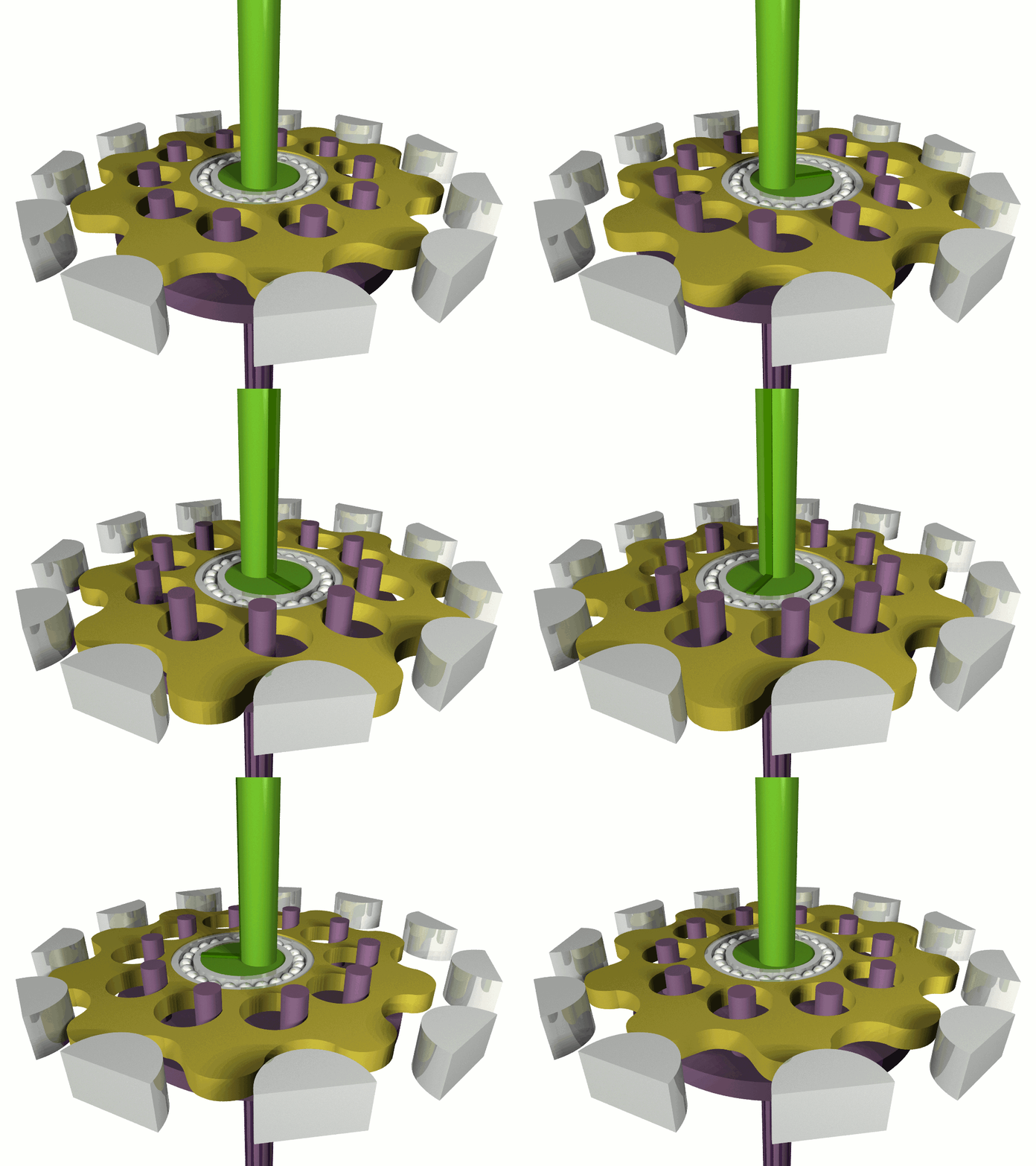
A cycloidal drive or cycloidal speed reducer is a mechanism for reducing the speed of an input shaft by a certain ratio. Cycloidal speed reducers are capable of relatively high ratios in compact sizes with very low backlash.The input shaft drives an eccentric bearing that in turn drives the cycloidal disc in an eccentric, cycloidal motion. The p...
Cycloidal gearboxes are low friction and easy to 3D print. This is one designed automatically by an open-source Python program.
rotund wedge
@vagrant thunder thank you so much! I do have a 3d printer and can continue my development! I was stumped for a few days as I am new to robotics and this helped a lot
 weak kelp
james burton have made some of those gearboxes
 proven lotus
^^ they're also not impossible to design on your own if you know cad pretty well
restive pike
I'm fairly sure that most robots use harmonic drives rather than cycloidal.
At least for normal ranges of loads for midsized ones.
rotund wedge
restive pike
I'm fairly sure that most robots use harmonic drives rather than cycloidal.
Thats possible, i just looked them up . Both seem to be applied in the same projects
vagrant thunder
While it’s true that harmonic drives have a higher torque density on average, harmonic drives are typically less accessible to hobbyists. 3d printing of cycloidal drives is much easier, though there are documented examples of people printing the strain wave gearing with TPU…
restive pike
True, depends on the project scale
Or go for the fanciest new robot on the block with these things:
https://motus-labs.com/
INNOVATIVE Geared Solutions The new family of precision geared solutions offers higher torque density and performance. The unique patented design utilizes
 proper kelp
Anyone have resources for smoothing tracking? Working on an auto pan/tilt and I'd like to smooth out overshoot, jitter, oscillations, etc.
Just curious whats out there that I havent found or thought about myself.
primal shell
I'm thinking the same sort of fluid damping mechanism used on tripod heads.
pine bramble
proper kelp
Anyone have resources for smoothing tracking? Working on an auto pan/tilt and I...
Are you talking hardware or software?
proper kelp
Software - the pan tilt itself is already smooth movement-wise but the object im tracking has some things about it that introduce some oscillations horizontally as well as occaisional sporadic movement.
to give an analog - imagine trying to track a bee thats moving somewhat randomly but average out the movement to make the tracking less jerky
pine bramble
proper kelp
Software - the pan tilt itself is already smooth movement-wise but the object im...
Then if you haven't already explored it, you might consider implementing a PID controller for each axis. There are various filters that can be added, or you can just do averaging, but the end result of a well-tuned PID controller is a configurable damping effect. You can in effect (through configuration) make it jerky or smooth, as you're effectively programming the "feel" of the motion. PID controllers can be designed to control either velocity or position, in your case position.
proper kelp
pine bramble
Then if you haven't already explored it, you might consider implementing a PID c...
interesting - PID was on my list to look in to. I need feedback for it to work, right? Its a little tricky since im using a mount that uses dc motors and theres not much room left but maybe i could add some pots or encoders. The camera also has an IMU but i dont know how accurate it is
pine bramble
Yes, feedback is essential for a PID controller. Some servos provide feedback. If not you could possibly use an optical or Hall effect encoder but some kind of potentiometer is probably necessary for a position encoder (I keep thinking velocity PID because that's what I do myself).
proper kelp
ill try with the IMU in the camera first. For reference - the pan/tilt im controlling is one of these but with the electronics replaced by a pi and motor controller: https://www.bhphotovideo.com/c/product/64399-REG/Bescor_MP101_MP_101_Motorized_Pan_Head.html
pine bramble
God, for that much money I'd hope it wouldn't need a supplemental PID controller. woof
proper kelp
the issue isnt the movement of the device - more so smoothing the tracking target
pine bramble
Ah
proper kelp
(also, i dont know when those got so expensive... they used to be 1/3 the price)
pine bramble
So the bee you're tracking is being located on your image? Like an X,Y position?
proper kelp
The bee was an example... the actual target is a cyr wheel performer. the things that make it tricky are 3 specific things:
-
the apparatus and performer is like a penny spinning off axis (creates oscillations in the x and y planes)
-
the performer introduces an elemnt of randomness in to the movement
-
my object tracking model is pretty good but its impossible to avoid mistakes in the bounding boxes
pine bramble
Yes, understood the bee was an example.
You can definitely use a PID controller. The "feedback" would be the horizontal and vertical error...
You'd feed that error into your PID controller and use its output to fix the position of the servos.
proper kelp
Thanks - thats exactly the type of advice i was looking for
pine bramble
The PID controller by its nature fixes that kind of thing. You'll need to learn how to tune a PID. You start with P, then usually D, then usually I, or I then D. But I'd recommend probably using three potentiometers with an ADC on each, rather than try to set the values in software manually. You'll save a lot of time. Sometimes you can get away with just a P controller, sometimes PD. Each situation is a bit different, hence there is no "standard" tuning.
But it sounds like that might work for you. It's a good skill to learn in any case.
I gotta go now, good luck!
proper kelp
thanks again!
 trim zinc
Hey there,
Here is other one of my basic questions 😄
So I have a mpu6050 imu, I am using with micropython and with this library
https://github.com/micropython-IMU/micropython-mpu9x50/blob/master/README_MPU9150.md
It has method imu.accel.xyz which returs 3 number.
(the letters facing to me, and the connectors are up, it is an adafruit qwiic sensor)
If I tilt the board front to back, the first number changes, so that is the X axxis
If I tilt the board right to left, the second number changes, so that is the Y axxis
But what is the 3 number. it changes depends on the movement, but I can't pinpoint the direction.
Please help me out. 😄

GitHub
Drivers for InvenSense inertial measurement units MPU9250, MPU9150, MPU6050 - micropython-mpu9x50/README_MPU9150.md at master · micropython-IMU/micropython-mpu9x50
vagrant thunder
trim zinc
Hey there,
Here is other one of my basic questions 😄
So I have a mpu6050 imu, ...
These are the axes typical of an accelerometer. Tilting is a simple way to test if it works, but to truly isolate the direction of interest, consider taking readings while shaking the device in one direction.
 cursive helm
That is a left handed co-ordinate system??? Is that correct? I would have expected +Z to be down or one of X,Y to be in the opposite direction shown.
THe diagrams on this one show a right handed system https://learn.adafruit.com/adafruit-analog-accelerometer-breakouts
lone skiff
You should go by the sensor datasheet to be sure, but chances are that Hem's image is generic rather than intended as documentation for the particular chip.
proper kelp
pine bramble
I gotta go now, good luck!
Implemented PID today - managed to get it pretty smooth! Thanks for the suggestion!
native cipher
wow! that's impressive.
Usually tuning PID is quite a challenge
pine bramble
proper kelp
Implemented PID today - managed to get it pretty smooth! Thanks for the suggest...
Ah, congratulations! Very impressive, as @native cipher says it's not a trivial thing to learn or do.
proper kelp
It was a long day of reading and watching videos. I think it helped that PID actually simplified a lot of hand-rolled "solutions" that id already tuned.
primal shell
I saw a PID demo unit once that used a light bulb as a heater. You could adjust the temperature set point and see the brightness of the bulb vary as the PID controller operated. It made it easier to see what oscillation and overshoot looked like.
proper kelp
Found some situations that need additional tuning! Mostly just looks like i need a lower passband for Kd
pine bramble
proper kelp
It was a long day of reading and watching videos. I think it helped that PID ac...
The first time I'd gotten my hand-written PID controller tuned and running on my robot, I put it down on the floor for a test. When I grabbed the robot while it was moving and the four motors resisted my pull, that was the first time it felt "intelligent" and alive. 😁
proper kelp
haha - I had a similar experience with my tracking tripod... its trained specifically for cyr wheel and the first version was looking down and away and was kind of dead... and the when i cam in to the frame it perked up and came "alive" in a really eerie way
 umbral vector
dumb questions. do (practically) all servos use the same controlling interface (1ms to 2ms), or is that just what all the adafruit shop does to keep things simple? i.e., can I just go to a random rc hobby store and buy a 3-wire 5v servo and expect it to work, or do I have to dig up the specs and such?
lone skiff
umbral vector
dumb questions. do (practically) all servos use the same controlling interface (...
Yes, that servo interface is fairly industry-standard, so off the shelf RC gear would generally work. There are some other communications protocols out there, but that's the least common denominator, so almost anything ought to support it one way or another.
vocal bear
What would folks' go to way to do back and forth motion without a linkage? I don't have the facilities to manufacture a 4 bar linkage
DC motor controller with limit switches seems pretty simple
lone skiff
Could you get away with like a piston arm on a motorized disc?
pine bramble
I wouldn't manufacture it, I'd either use hardware from ServoCity/goBILDA or visit my local RC hobby shop and browse for ball-and-socket joints or other possibilities.
vocal bear
Ahh yeah I could try thay
Gotta do some math re: weights
I've got a DC gear motor here that has a sticker on it with some parameters one is:
F/L RPM : Number
What does F/L stand for?
Additionally, is it possible to make a 4 bar like shown and attach something to the pivot point like shown?

I guess you could do your fixturing to the rocker in such a way that it's equivalent
But it would be most beneficial in my case to have the pivot point be a shaft that rotates with the rocker.
Wondering if you can do that with off the shelf parts
lone skiff
vocal bear
I've got a DC gear motor here that has a sticker on it with some parameters one ...
Possibly that's "full load".
vocal bear
As in mechanical load?
Hmmm I was thinking it's the rated RPM with the rated voltage and nothing attached.
 snow ridge
hey, so I'm wanting to make a small robotic spider for a project of mine, and I'm kinda stuck on how to make a joint that can move up/down and left/right while still being compact. The main body is gonna be just a bit bigger than the dimensions of a pi3 for the width and length. I'm still in the early part of design, don't have any CAD models yet. Does anyone know of some actuator that'd help me make such a joint?
I was thinking standard RC servos, but to make the joint move how I want would make it too large, especially considering each leg needs one of these at the base
pine bramble
snow ridge
hey, so I'm wanting to make a small robotic spider for a project of mine, and I'...
You might check out: https://www.servocity.com/standard-hub-shaft-servoblock-24t-spline/

You might also check out how others have done this: https://www.robotshop.com/en/catalogsearch/result/?q=spider&order=relevance&dir=desc
snow ridge
ok, cool I have better ideas now how to do it. I'm gonna make the base move forward/backwards and the middle joint do in/out movement
pine bramble
Even the Adeept spider is using two microservos per leg and what looks like acrylic plastic for the structure. I'd probably avoid acrylic as it cracks easily and maybe use Delrin or PC board. But it's not easy to keep the weight and size down. By the time you add chassis, servos, electronics and a battery you've got enough weight that your battery life is very low. That's one of the challenges on any small robot.
https://www.robotshop.com/en/adeept-hexapod-spider-robot-kit-with-pixie.html
snow ridge
ok, what I was thinking was a 3d printed body. I want to do small scale but I have no experience with robotics really, as far as design
pine bramble
snow ridge
ok, what I was thinking was a 3d printed body. I want to do small scale but I ha...
Sounds like an interesting project. You gotta start somewhere and I guarantee you won't get it right the first time. But that's the nature of experiments. Have fun!
snow ridge
pine bramble
Sounds like an interesting project. You gotta start somewhere and I guarantee yo...
yeah, true. Thanks! I love this kinda stuff and wanna branch out into the physical world more with my projects
pine bramble
snow ridge
ok, what I was thinking was a 3d printed body. I want to do small scale but I ha...
If you've never built any robot before you might work your way up to a spider, which is one of the more difficult styles of robots. You can also consider whether you want it to be simply a remote-controlled device or whether you want it to be more of a robot, i.e., have sensors, be semi-autonomous or fully autonomous. Lots of options!
snow ridge
oh, I didnt realize they were a more difficult style lol. Maybe I'll just do like a robotic arm for now. I'm wanting to make it semi-autonomous initially
primal shell
snow ridge
ok, what I was thinking was a 3d printed body. I want to do small scale but I ha...
That's the approach I'm taking, but mine isn't particularly compact
 snow ridge
primal shell
That's the approach I'm taking, but mine isn't particularly compact
snow ridge
primal shell
That's the approach I'm taking, but mine isn't particularly compact
oh neat, I've decided for now I'm gonna do something simpler lol so I can learn robotics. Never gotten into it really
primal shell
A bunch of the things I build don't end up working the way I imagined, but I'm learning a lot and having a good time
snow ridge
oh fun lol, the important part is learning and having a good time
mint dust
snow ridge
hey, so I'm wanting to make a small robotic spider for a project of mine, and I'...
This might be a good source of inspiration, i would say it's relatively compact https://www.thingiverse.com/thing:1021540

HEXRO is a small Hexapod robot designed to work with any microcontroller and servo motor controller.
pine bramble
mint dust
This might be a good source of inspiration, i would say it's relatively compact ...
I'm assuming anyone building this either accepts almost zero battery life or is expecting to run it via a power cable... 12 servos will eat up a LiPo battery in no time, and one would also have to be careful not to run all the servos at once, as the current draw is potentially 12x the stall current of one servo. (just so anyone building this goes into with eyes open)
mint dust
I built one a while ago, but stretched/extended it horizontally to have room for a larger battery.
pine bramble
mint dust
I built one a while ago, but stretched/extended it horizontally to have room for...
What kind of battery life were you getting?
mint dust
pine bramble
What kind of battery life were you getting?
Admittedly I did not end up running it off the battery long enough to kill it- I was running off two 18650, approx 3000mAh. but given it uses 12 sg90, which stall at ~400mA (according to https://protosupplies.com/product/servo-motor-micro-sg90/), x12=4800mAh, it would for over half an hour while stalling all 12 servos at once (assuming that the MCU/other peripherals are negligible relative to the servos), so I imagine it'd be pretty respectable under normal operation. But you're right in that pulling 4800mA from a 1C 3000mAh battery would be bad news.
This was as far as I got before I moved on to another project. (and this was taken before expanding it horizontally) The stuttering is from crappy connection thru female jumpers, not power supply issues. https://www.youtube.com/watch?v=mj_J4tXOlOQ&feature=youtu.be

Loose connection due to cheap jumper wires necessitates I hold the ESP32 in my hand while it runs.. it is completely wireless though
 true condor
I'm designing a device using one of these little steppers and controllers https://medium.com/jungletronics/uln2003-28byj-48-stepper-motor-f1cc5357eff which will rotate a lightweight indicator arm (think like a traditional wall clock) controlled by a FeatherS2. So I don't expect substantial current draw from the stepper controller. What's the best strategy for powering such a device from A/C? I was thinking a high quality 9V wall wart which would power the motor controller which can run on 5-12VDC, and then I'd use a LM7805 5V regulator to power the Feather. Is this a suitable design or does anyone have recommendations for something better? Perhaps since the motor won't be working hard, I can get away with a good commodity 2A 5V USB wall transformer to power everything. What I don't know how to characterize is the potential for the motor driver to pull that 5 Volts down and cause the Feather to fail.
 primal shell
true condor
I'm designing a device using one of these little steppers and controllers https:...
primal shell
true condor
I'm designing a device using one of these little steppers and controllers https:...
That should work. You could possibly also run everything from an ordinary 5V USB power supply.
true condor
I suppose I could test everything on a single 5V supply and watch the DC on an o-scope to see if there are any dips while I resist the stepper shaft and make it do some real work.
primal shell
That's a good idea. Normally I avoid powering logic and actuators from the same supply, but the Feather regulates the 5V down to 3.3V internally, so some dips in the 5V will be less likely to affect it.
true condor
Same project, different question:
I'm using circuitpython and adafruit_motor, getting motor to turn CW for motor.onestep(stepper.FORWARD, style=stepper.DOUBLE) however changing that to stepper.BACKWARD results in no change, the motor still turns CW.
Wondering if somehow my pin assignments are wrong.
lone skiff
That's weird. You might try dropping back to SINGLE coil activation, since it could make it easier to detect any wiring issues to have only one going at a time.
true condor
SINGLE makes the motor behave erratically.
I should post the code. Do people do that in backticks or by referencing github?
lone skiff
Backticks if it's a dozen lines or so. Github or pastebin if it's longer.
If it's behaving erratically, you might try doing a very slow rotation where you can visually see each individual coil switch. You might spot a pattern like it's only activating even steps and disconnected on odd steps.
true condor
Pastebin
Pastebin.com is the number one paste tool since 2002. Pastebin is a website where you can store text online for a set period of time.
btw so far I am assuming that D9, D10, D11 and D12 should be wired to the controller's In1, In2, In3 and In4, in that order ... but that bothers me that I have to assume that
lone skiff
Also doing 100 steps/second might just be too fast for your motor and load, so the first thing I'd do is slow that down a bit if you haven't already.
lone skiff
That's... 1500 steps per revolution? That seems quite high. Is your stepper geared down?
true condor
I'm seeing about 2000 steps per rev
it's just a stock motor, here:

I'll slow it down so that i can watch the light patterns on the controller.
lone skiff
Yeah, that has a 16:1 gearbox on it. So the motor itself is 32 steps/rev.
true condor
I'm seeing four light patterns, meaning, four commands per step. e.g. 1001, 0110, etc.
lone skiff
You might try it even slower if you're seeing 2000 steps/rev, though... sounds like you might be skipping steps, leading to the erratic behavior.
lone skiff
Although with the 4 commands/step, it might just be confusion with what a "step" is, too, since there's a 4:1 discrepancy between the 2000 you see and the 500 the motor should have.
true condor
correction, it's moving one step for every two commands.
ie i feel it move every two commands. 0110 (steps), 1010, 1001(steps), 0101
lone skiff
Sound like one of the coils is not fully connected, so I'd double-check the wiring to see if something is loose.
true condor
ok
true condor
Turns out that swapping In2 and In3 on the UNL2003 driver board solved the problem of not being able to reverse. thanks again @lone skiff and @madbodgear
 dapper herald
hey all, wondering if someone could help me with a basic switch question. I've got a push button rated at 36v DC/2A. I've read that rating a switch is somewhat experimentally done, and that as a basic rule lower voltage allows for a higher current. All that said, I would like to know if using this switch with a 5V/6A power supply long term is likely to cause any issues? Is there a rule of thumb maybe that I dont know about for switch ratings?
cheers!
here's a link to the switch
https://www.alibaba.com/product-detail/hban-12mm-flat-head-1no1nc-spdt_60272672012.html?spm=a2756.order-detail-ta-ta-b.0.0.61f92fc2iw32sx
Hban 12mm Flat Head 1no1nc Spdt 3 Pins Stainless Steel Latching Electric Mini Push Switch - Buy Flat Round Head Push Button Normally Open Normally Close Metal Anti-vandal Latching Switch,12mm 1no1nc Self-locking On Off Push Button Stainless Steel Electric Switch Price,Anti Vandal Stainless Steel Metal Button 12mm Flat Head 1no1nc Latching Mini P...
vocal bear
Do they make servos with indices?
lone skiff
vocal bear
Do they make servos with indices?
You may want to unwrap that question a little bit. A garden variety position-driven servo will indeed have a home position, if that's what you mean.
vocal bear
Hmm ok
Yeah I need to make something that rotates back and forth. I would use a simple crank rocker but it needs to always end up in the same position. So that means more active control/timing.
lone skiff
Sometimes people will add one or more limit switches, both to define a reference position and to keep the actuator from going too far.
vocal bear
that's the other thing I was thinking
vagrant thunder
dapper herald
hey all, wondering if someone could help me with a basic switch question. I've g...
For stuff like this, you usually don’t want to exceed either the voltage or current rating. Power may be equivalent, but if it’s not written as a Watt, you shouldn’t assume it is. Higher current can generate more heat from resistive losses, so it’s best to not make those assumptions, especially if you plan to use it long term.
dapper herald
vagrant thunder
For stuff like this, you usually don’t want to exceed either the voltage or curr...
ok cool thanks for the advice Hem. Cheers
pine bramble
vagrant thunder
For stuff like this, you usually don’t want to exceed either the voltage or curr...
I can't remember exactly as this was many years ago, but basically the voltage rating gives you an indication of whether or not arcing might happen across the contacts beyond the specified voltage, and the current rating is the maximum that the switch can handle when closed. Or something like that. But agreed, you really don't want to exceed either value, and in general you really should stay a comfortable percentage below the values if there's any uncertainty such as potential surges in the circuit. So if I'm using a 5v circuit I'll spec out 15v rather than 6v capacitors, etc. It's always better to be on the safe side, overengineer rather than underengineer.
vocal bear
Is there a way to estimate the RPM of a brushed DC motor with just a voltage applied across it (no controls) if you know the moment of inertia of the load?
lone skiff
Well, the steady-state RPM will be due to the friction rather than the moment of inertia. The latter would affect the ramp-up acceleration phase.
vocal bear
Ah yeah
So I'd need to estimate the stiction in my system somehow?
I guess I could just assume it's going to be some value less than the NL RPM and call it a day
lone skiff
Note that friction would dominate in just a free-spinning mass. But often a motor will have some actual work-performing load on it that will be bigger than that.
vocal bear
Yeah it's just a free spinning mass. Work performing load? Like a wheel?
lone skiff
Yeah, like... a pulley lifting a weight, or mixing concrete, or whatever.
vocal bear
Ahh
native cipher
usually any motor datasheet lists no-load RPM
 brittle prawn
I’m not really sure where to ask this but I have this motor that I was planning to use for a project but I’m not sure what the extra magnet and stuff is used for an if I can take it off without downsides

I’m used to seeing motors like this and I’m just assuming that it’s a different style but why is it there?
 vocal bear
That looks like someone added an LC circuit to your motor. What is the motor's provenance?
brittle prawn
Not really sure what you mean but I got it out of an old RC car laying around
vocal bear
That's what I meant 🙂
for the small orange disk, is one lead attached to each pole of the motor?
vocal bear
hmmm well it won't do anything in that configuration. Is there any evidence that it was ever attached to both poles?
brittle prawn
 vocal bear
hmm hard to tell
brittle prawn
I also have this motor that looks similar but slightly smaller that I want to use for the same project

@vocal bear Any ideas on if I need it?
vocal bear
Looking into it!
vocal bear
brittle prawn
<@!887510739462537236> Any ideas on if I need it?
The capacitor is to reduce EMI caused by arcing between the brushes and commutator (https://electronics.stackexchange.com/questions/490934/why-do-we-use-capacitors-in-parallel-with-dc-motors/491035) Looking into the other component
If you're going to use that first motor, I would solder the loose leg of the capacitor to the empty pole of the motor
 vocal bear
Ahh i see
Looks like it's soldered to the can and then the can is soldered to the other pole
brittle prawn
Probably
primal shell
brittle prawn
I’m not really sure where to ask this but I have this motor that I was planning ...
That's filtering components to cut down on electrical noise: a capacitor across the terminals to absorb spikes, and (probably) a common mode filter on the power leads to impede propagation of interference. The motor will work fine without them, but if you have other sensitive circuitry nearby or hooked to the same power leads, those filtering components can help avoid disturbances.
brittle prawn
primal shell
That's filtering components to cut down on electrical noise: a capacitor across...
My idea is to have this motor wired into a battery to put electricity into the battery by spinning it, in this case does it matter?
Or would this idea work with this type of motor
primal shell
No, it wouldn't matter. That does look like an ordinary brushed DC motor, and those generally work well as generators.
sly sand
They probably experienced erratic operation of the rc vehicle in the presence of the RF transmitter controlling it.
This is a cheap fix that pretty much incidentally blocks the RF from getting into the circuits controlling the car.
That'd be my guess /if_this_were_a_game_show
I've seen CB rigs that did this .. to themselves. If you use an indoor antenna and aren't careful enough, the RF gets into the rig and resets digital settings somewhat randomly.
The Buddipole antenna feedpoint coax fittings have 5-7 ferrite beads on the end of the coax where it meets the center insulator of the dipole antenna it is meant to make.
They encased all the beads in a single piece of (tubular) heat shrink.
It makes a pretty big difference. ;)
Looks like they only offer a choke balun in the new catalog:
I'm going to go out on a limb and suggest, in the absence of an RF transmitter nearby, your choke does nothing of interest.
proper kelp
Looking to add an encoder to my project to help track position. I'm trying to navigate specs - specifically angular error. If an encoder has a minimum error of +/- .5 degrees and a maxmimum of +/- 1.5 degrees - I would need to multiply this by my gear ratio to get my maximum error, right?
For example:
If the encoder rotates 10 times for a single 360 degree rotation of my platform, then the maximum error would be +/- 15 degrees worst case scenario?
Since the error is +/- should I treat it like noise? aka - the error isn't correlated so I can expect a certain amount of cancellation lowering the actual maximum error?
lone skiff
The ratio would go the other way, I think. If the error in the encoder is 1.5 degrees, but it goes 10x the speed of your platform, then the platform angular error would be 0.15 degrees.
And you probably can't assume uncorrelated errors. It's usually not just electrical noise, but things like the encoder disc not being perfectly circular or on-axis with the bearings, etc. So you could totally have a situation where it consistently is 1 degree off on the left side of the rotation and -1 degree on the right side, etc.
proper kelp
Ahh, I see why it goes the other way now. Thanks!
Actually, that .15 would be the errors effect per rotation of the encoder, so the error just stays the same for the entire 360 degree rotation of the platform I think? Maybe I'm overthinking it?
lone skiff
Can you rephrase? I don't quite follow.
proper kelp
If the encoder has an error of 1.5 degrees per rotation. 1 full rotation of the encoder is 36 degrees of rotation for the platform (it spins 10 times for every 1 full rotation of the platform). So the error for every 36 degrees of rotation is .15, but there are 10 of those for a full 360 degree rotation of the platform and assuming they can be correlated that adds back up to 1.5 degrees of total error.
lone skiff
It's not 1.5 degrees per rotation, it's just 1.5 degrees for any single position reading. The errors won't accumulate over multiple rotations because the encoder comes back to the same position over and over.
That is, the encoder will always accurately know that 360 degrees is 360 degrees (give or take a little readout noise), since that's guaranteed mechanically.
proper kelp
ahh, Thank you - I'm a programming not a mechanical engineer so it takes me a little while to understand this stuff
lone skiff
Note that once you get down into fractions of a degree, you might also have some platform angular error from, say, gearing slop and backlash between the platform and the encoder.
primal shell
lone skiff
It's not 1.5 degrees per rotation, it's just 1.5 degrees for any single position...
So differential nonlinearity (DNL), not integral nonlinearity (INL). I normally see these terms in reference to digital to analog converters (ADC), but it seems like they'd apply here.
 plain pasture
Hey guys been a long time since I've been here
I was looking for a list of electric linear actuators
For eg, if I needed a large push/ pull solenoid what would I have to Google
Like a LARRRGE one
lone skiff
You seem to have the normal terms already. However, you may want to consider what type of actuator you need... for large loads you'd usually see things like lead-screw actuators instead of a direct solenoid drive.
 turbid trail

Linear actuators convert the rotation of a DC or stepper motor into linear motion, allowing you to push or pull objects. Versions with feedback or integrated stepper motors allow for precise position control.
not cheap
@plain pasture ^^
primal shell
Can be had cheap in the form of the old 3-meter satellite dish positioners.
plain pasture
Tysm will look into it
plain pasture
lone skiff
You seem to have the normal terms already. However, you may want to consider wha...
So "actuators" is all i need? Any other term?
plain pasture
primal shell
Can be had cheap in the form of the old 3-meter satellite dish positioners.
Thanks for that idea
 plain pasture
Aight will check tysmmmm
vocal bear
What would be a good way to attach a shaft to a rectangular piece of 0.25" acrylic? Such that the axis of the shaft is perpendicular to the plane of the acrylic
primal shell
vocal bear
What would be a good way to attach a shaft to a rectangular piece of 0.25" acryl...
Maybe a pipe flange?
vocal bear
I was considering that.
It's a small width of plastic and I don't have the shaft diameter nailed down yet
pine bramble
You can also use a section of acrylic tubing with ID and OD to match your requirements. Acrylic glues well with cyanoacrylic, so you could get a pretty solid join between the tube and the plate. Of course, the thicker the wall of the tube the more surface area, the stronger the weld.
vocal bear
You mean ID matching the shaft diameter?
pine bramble
Yes. There's also ServoCity/goBILDA hubs: https://www.gobilda.com/hubs/
goBILDA is a modern build system designed for engineers, artists, students and makers. It's metric, lightweight, and has an ever-growing library of parts
ServoCity: imperial measurement; goBILDA: metric
They're sorted by shaft diameter.
vocal bear
I was thinking a hub would be a good fallback if there wasn't a clear suggestion
I can laser a hole pattern in the acrylic plate
pine bramble
The lower end of those is about $5 so I'd probably go with a hub. It'll be centered, have four screws, and be extremely strong.
D shaft or round or hex
vocal bear
Hmm I'll have to shop for another motor, the one I was hoping to repurpose has a .31" shaft
maybe it's 8mm, unsure
pine bramble
vocal bear
maybe it's 8mm, unsure
That seems to be the closest metric value.
Then you've got: https://www.gobilda.com/8mm-round-bore-hubs/
goBILDA is a modern build system designed for engineers, artists, students and makers. It's metric, lightweight, and has an ever-growing library of parts
Those are a bit more expensive but I can say that they are things of beauty, if you like machined parts. I'm using both (in 6mm bore) on one of my robots.
vocal bear
I only need one and my budget can support it
But I'll need to find a shaft coupler that can go from 8mm D to 8mm round
pine bramble
vocal bear
But I'll need to find a shaft coupler that can go from 8mm D to 8mm round
You mean in order to go from the motor's D shaft to the hub?
vocal bear
motor shaft to main shaft to hub
there's some distance between the motor and the piece of acrylic, I'll need mounted bearings too
pine bramble
I hate to sound like a saleperson for goBILDA (I don't work for them, just a customer) but of course they do sell all that stuff, as do other vendors like Pololu. I've posted a list of robotics vendors at: https://service.robots.org.nz/wiki/Wiki.jsp?page=Vendors
vocal bear
yeah I was just looking at their offerings. Getting it all in one place would be best
sigh, gobilda has nearly what I need but not exactly
I guess I can always spec a new motor that doesn't have a keyed shaft
pine bramble
A round collar will still clamp onto a D shaft. Not sure what the problem is there. ?
So long as the key is less than half the portion of the shaft...
If it's a half D then yeah, different motor would be an option.
vocal bear
Yeah I need to finish the math the see if this motor will be suitable
vocal bear
So I've done some basic, idealized math, and the initial acceleration of my motor should be ~12 rad/s^2. It's likely a high estimate and of course the motor isn't going to spin forever at that acceleration. How can I figure out what the top speed of my motor will be given a mass moment of inertia?
I have the no-load RPM of the motor and the No-load torque
primal shell
Inertia isn't the limiting factor, drag is.
lone skiff
Yep. At maximum speed, the motor will be somewhere along its power curve... if the friction it zero, it would be at the no-load RPM. If the friction is finite (or there's some other work that the motor is doing in this system), then the RPM will be slower based on how hard the motor has to work.
vocal bear
hmm ok
So I'd need to know the friction of the system then? And does the friction change with speed?
lone skiff
Yes, and generally yes. Honestly this is going to be challenging to predict ahead of time more accurately than "there's not much friction, so it'll probably max out at 75% of the no-load RPM" or something like that. It's the sort of thing you'd need to measure after you build it, more or less, unless you have a very good simulation model of the system.
vocal bear
bummer yeah I don't
have a good simulation
Well I'll just have to hope it works out
lone skiff
Incidentally, 12 rad/sec^2 is fairly fast in my imagination, going from 0 to 100 RPM in about a second.
vocal bear
Yeah that's what I was thinking too
F/L Speed is only 16 RPM though
Why does speed increase with decreasing torque? I feel like I should know this
 lone skiff
To a first approximation, it's just equalizing the power of the motor. Power = torque * angular velocity, just like power = force * velocity in linear motion.
vocal bear
ahh
Which of these orientations does it look like I have? I feel like it's A https://www.molon.com/images/pdf/custom-dc_CHM.pdf
 lone skiff
Yeah, I'd tend to agree. That matches the part number in the list, too. You can double-check with a ruler.
vocal bear
Any recommendations for companies for shaft couplers? goBilda doesn't seem to have any 8mm to 8mm
hmm misumi doesn't either. I must be missing something obvious. Is there another way to join two shafts?
lone skiff

ServoCity
vocal bear
Ah should have checked there
thanks!
looks like they don't have flexible but I may have to just live with it
native cipher
what kind of shafts?
round/D/hex?
set screws are a nightmare, so if there is any way for you to replace your shafts with hex ones, it'd make everything so much easier...
vocal bear
Let me see if I can use hex
vocal bear
native cipher
what kind of shafts?
round/D/hex?
This should work (https://www.gobilda.com/4007-series-hyper-coupler-8mm-round-bore-to-8mm-rex-bore/). The shaft on the motor is 8mm D but I guess round should work
vocal bear
I'm looking at goBilda REX shafting and I don't see a way to tell what the fillet radius is on the points of the hex profile. Does anyone know that?
Ah I think I see
native cipher
I think they literally take intersection of hexagon and circle.
Hexagon with 7mm flat to flat has diameter of 8.083 mm
vocal bear
Something like this (dims in inches), and then trim out the points

yeah we're saying the samet hing haha
Now to figure out what the chamfer is
native cipher
but yes, I would certainly suggest using the clamping hypercoupler instead of set screw coupler.
set screw hubs and couplers are always trouble, have used enough of them to never want to touch them again
you have seen that goBilda provides step files of their components, right?
vocal bear
Yeah, but I want to be able to easily make a shaft of arbitrary length
also was curious
vocal bear
yeah but their REX stuff claims to work well in round bearings
and I can always cut that to length
pine bramble
native cipher
set screws are a nightmare, so if there is any way for you to replace your shaft...
I agree that's generally the case, but there are goBILDA/ServoCity hubs that use set screws that don't screw into the shaft but tighten the entire hub around the shaft, and these seem to avoid the general problem of the set screw being the single point of failure in either slipping around the shaft or loosening because they're a relatively tiny component taking the strain and shocks. Specifically, the Hyper hubs use a SS 3mm hex drive screw to clamp the entire shaft, and the Sonic hubs use two. On hex and D shafts this would be pretty foolproof, and while I agree on round shafts there's still the possibility of rotation inside the hub, I do think the Hyper and Sonic hubs are probably the best solution I've seen. The motors I've been using have all be D shafts so I guess I've been spared the experimenter's fate.
native cipher
I agree that's generally the case, but there are goBILDA/ServoCity hubs that use set screws that don't screw into the shaft but tighten the entire hub around the shaft
Sure, that's what I call "clamping hubs". When I talked about set screws, I meant those that go into the shaft.
 night trout
Hey everyone! So I'm testing an IMU and it works perfectly, but the script will sometimes error due to the i2c losing its connection for a second. Right now, I just use wires like in the picture. Is there a better way of doing it without soldering? I could solder it and I have something to remove the solder afterwards, but I was just wondering whether there's something better haha. thanks in advance!
 cursive helm
night trout
Hey everyone! So I'm testing an IMU and it works perfectly, but the script will ...
cursive helm
night trout
Hey everyone! So I'm testing an IMU and it works perfectly, but the script will ...
I have used these https://www.adafruit.com/product/3825 with clips (you might be able to solder wires to them).. Soldering header pins to the board works best though.
Just plugging the jumper into the holes does not work well -- as you have found.
 night trout
Oh thanks! Ill look into those
cursive helm
this type of clip lead also works well with them https://www.digikey.com/en/products/detail/sparkfun-electronics/CAB-09741/7056461?utm_adgroup=Test Leads - Jumper%2C Specialty&utm_source=google&utm_medium=cpc&utm_campaign=Shopping_Product_Test and Measurement&utm_term=&utm_content=Test Leads - Jumper%2C Specialty&gclid=CjwKCAiAvOeQBhBkEiwAxutUVO0fxj8-3bgru4XZjCWhSFegV-b7GLO6XrUHRlXJLSQ4Z5FlWGBq5BoCjFgQAvD_BwE
pine bramble
night trout
Your photo shows single pin connections of what are commonly called Dupont connectors, 0.1" grid male and female connectors housed in plastic housings, usually single or double rows which match the same 0.1" grid of the Raspberry Pi's GPIO bus (and most of the electronics industry hardware). You can buy kits of empty shells and either crimp or solder your own. I've been using Dupont connectors on all my robots for years now, and while crimping is easier, I generally hand-solder all my connectors. I recommend strongly against using the Dupont male connectors as the pins are very weak, but the combination of metal header pins and Dupont female sockets is pretty reliable, especially when grouped rather than single pins, as that stops any possible rotation. Here's a photo of a test rig with a Pi Zero W connected to a BNO085 IMU, the sister to the BNO055. You can see the five pin connector between the PI and the IMU, with only four wires used (the INT pin isn't necessary).
Also note that I2C connections are less reliable as a factor of distance and device count, though you should be fine if you keep your wire length less than about a foot. I'm using about fifteen I2C devices on one of my robots with no issues (and no messing with clock speed either).

While I make my own and you can also buy "jumper-jerky" (pull-apart rainbow ribbon cable with connectors at both ends) it looks like Adafruit also sell some ready-made Dupont cables, e.g.,
https://www.adafruit.com/product/4937

These jumper cables are exactly what you need to connect common 0.1" header devices together. Sure you can tape together individual 1x1 header jumpers, but why not do it right? Use with ...
 candid beacon
I'm using the Adafruit 16-Channel 12-bit PWM/Servo Shield and scoured the internet looking for something that would give me control of 4 servos with potentiometers. I could go without the board I know but think it would be better to get the boards protection. The example script from adafruit does not point me where to go and I'm not that good a programmer. If anyone has a link to a resource it would be greatly appreciated. Not sure where to start.
pine bramble
candid beacon
I'm using the Adafruit 16-Channel 12-bit PWM/Servo Shield and scoured the inte...
You've got one half of that equation with the servo shield. What you need are either four analog or digital potentiometers and either an ADC (analog-to-digital converter) for each or a software library (respectively), then your own code to take the values from the pots and send them to your servo controller. I don't believe there's a ready-made solution for that but everything is available in terms of hardware. Your code would be the glue that ties it all together.
I did something similar with three analog potentiometers to gain three red, green and blue values to control an LED's color. I used this:
https://shop.pimoroni.com/products/ads1015-adc-breakout?variant=27859155026003
as well as the Adafruit board that uses the same chip:
https://www.adafruit.com/product/1083
But as you need four channels you'd want to use a four channel ADC. Digital pots are available but 4x the cost of one makes your project fairly expensive compared to how cheap analog pots are.
Another option would be to use of the RP2040 boards that exposes all four of its ADCs, such as the Itsy Bitsy RP2040. That is, if you're not already using an MCU that has four ADCs.
 fresh crown
I'm pondering if there are ways to cheaply switch between analog inputs for a single ADC
candid beacon
Should be all there on the board. I just don't know how to code the pots with the I2C in a reasonable fashion. The Adafruit example only includes a full sweep and that is automated. I needs some map commands. I am programming a EEZY MK II robot arm tutorial for some STEM kids I tutor.
pine bramble
fresh crown
I'm pondering if there are ways to cheaply switch between analog inputs for a si...
That sounds like significantly more work than simply using an ADC with four channels.
...as now you need four, entirely transparent digital switches. Analog ones may alter the voltages from the pots. It's certainly possible but as I said, a lot more work than necessary.
fresh crown
always easier to throw chips at something, but in theory a transistor as a switch for each input?
pine bramble
fresh crown
always easier to throw chips at something, but in theory a transistor as a switc...
Yes, but if you're measuring analog signals that will change the input voltage to the ADC. And frankly, again, is it worth the trouble for four channels? If you were multiplexing 100 sure.
fresh crown
theory and potentials, also, 40 cents of transistors or a $10 chip
pine bramble
Remember than an ADC is measuring a voltage. If you alter that voltage you're no longer measuring the output from the pot.
fresh crown
be cheaper to gang two pi picos together in some cases
pine bramble
I don't spend hours and hours of my time for $10 but you're free to...
fresh crown
shouldn't take THAT long, but, sure
pine bramble
I think mostly it's just a much less accurate and less straightforward solution, kinda heading into the "unnecessarily complicated" territory. You either already have four ADCs if you're using a common MCU, or you buy one $10 device that has four channels. You might find a one channel ADC but it'll still be a few dollars.
fresh crown
I think even an attiny has an ADC
pine bramble
Yes, the series of ATtiny chips generally have a single ADC. On the other hand, many of the Teensy boards multiplex up to dozens of pins, which is where you can manage a lot of analog inputs. E.g., the Teensy 4.1 has 18 analog inputs, the Itsy Bitsy M4 Express (an ATSAMD51) has 7 analog pins, the Itsy Bitsy RP2040 has four. Multiplexers in this case are all built in.
night trout
Hey everyone! I have a robot with three wheels. The back two have a motor and the front one doesn't. To run the motors, I use the adafruit shield and a kit.motor1.throttle = 0.5 command for example. When I set the throttle for the left motor at 1, the right one will need about 0.8 for the robot to go straight but this isn't always the case. I was wondering whether there's a better way, possibly using a sensor, to make the robot go straight. Could anyone help me out? Thanks in advance!
vagrant thunder
night trout
Hey everyone! I have a robot with three wheels. The back two have a motor and th...
There are many ways to make this robot go straight, but unless you can diagnose the root cause of the issue, you will need replacement or additional hardware to accomplish this. The most surefire way would be to use encoders and a closed loop feedback control, but there's also an approach that uses steppers/BLDC and open loop control. If the issue is your third wheel not swiveling properly, that could also cause issues with driving straight, and might just take a mechanical fix. However, seeing one motor outpacing the other by about 20%, you're likely either using cheap motors with poor tolerances, or mismatched motors that probably shouldn't be used together in the configuration you have.
If you can share your robot design in more detail, there may be other fixes to try, but it's hard to judge with the information given.
night trout
The motors are pretty cheap I'm pretty sure, I'll send you the design in a second. I absolutely hate working with this thing haha. Do you think an IMU (with an accelerometer) could help?
vagrant thunder
It could, if you can write the software to make the adjustments. The response might be slower than the encoder approach, but it's probably more cost-effective.
vagrant thunder
Ahhh, that's a real budget motor. If you have a multimeter, you could check and see if the two motors have the same resistance to make sure they get the same amount of current? 20% is a big difference, I wonder if one of the motors is out of spec...
night trout
Actually, I don't think the motors are the problem, it's the front wheel. If it is pointed even slightly to the right, the robot will go right and if it is pointed to the left, it'll go left (when I use the same throttle value for both motors). I'm not sure why it mainly wen't straight when the left motor had 20% more throttle
night trout
vagrant thunder
Ahhh, that's a real budget motor. If you have a multimeter, you could check and ...
I'll try it out, voltage is about the same last time I checked
vagrant thunder
night trout
Actually, I don't think the motors are the problem, it's the front wheel. If it ...
Ah, then maybe some lubricant might do the trick?
Get some WD-40 on that caster wheel between the wheel support and the mounting plate haha
night trout
will try it out! haha
vagrant thunder
If not, you probably have too much weight on the caster wheel, and could consider redistributing the weight or replacing it with something nicer. Maybe a ball caster, if you can get it to the right height?
vocal bear
How can I tell if a servo has a "return to 0 position" functionality?
vagrant thunder
vocal bear
How can I tell if a servo has a "return to 0 position" functionality?
What is a "return to 0" functionality?
vocal bear
like it has a home position that it knows how to get back to, even if you power it off when it's turned to an angle?
vagrant thunder
All non-continuous servos have a feedback controller that handles its absolute position. You can think of a servo as a motor attached to a potentiometer and a small position controller to position a servo to an angle as provided by the PWM input.
vocal bear
nice! And do they make servos that you can send a PWM signal for a position and they send a signal back when it's reached the position?
vagrant thunder
vocal bear
nice! And do they make servos that you can send a PWM signal for a position and ...
No, but there are some servos with modifications made to provide its feedback signal back to the MCU. https://www.adafruit.com/product/1404?

It looks like a servo, it acts like a servo, but it's more than just a servo! We got a factory to custom-make these classic 'standard' sized hobby servos with a twist - the ...
 vocal bear
hmm looking at the specs of that servo, it might just fit my needs
thanks!
Does it have a plastic spline?
vagrant thunder
Judging from the pictures, yes. https://www.adafruit.com/product/1450 is metal, but it's a size down.

It looks like a micro servo, it acts like a micro servo, but it's more than just a micro servo! We got a factory to custom-make these quality metal-geared 'micro' sized hobby ...
vocal bear
much weaker. I'll see if anyone else sells them
vagrant thunder
A standard servo motor with analog voltage feedback, compatible with Arduino Servo library.
Plenty of options out there haha
vocal bear
I could always do it with timing too
vagrant thunder

This version of the FS5115M high-torque servo from FEETECH is specially modified to provide access to the feedback potentiometer through a fourth (green) wire, allowing you to directly measure the position of the output. This extra information enables more complex robotics applications, such as determining when the servo has reached its target,...
vagrant thunder
vocal bear
I could always do it with timing too
If you have voltage regulation, there shouldn't be any issues with this approach, either.
vocal bear
voltage regulation?
vagrant thunder
If you run these off of a battery and the voltage dips, your timings might get thrown off.
vocal bear
ah, yeah I'm running off the wall
this https://www.dfrobot.com/product-1709.html is the same basic footprint as this https://www.gobilda.com/2000-series-dual-mode-servo-25-4-super-speed/ right?
vagrant thunder
vocal bear
this <https://www.dfrobot.com/product-1709.html> is the same basic footprint as ...
Close, but the numbers are slightly different.
vocal bear
shucks
may have to do it with plain timing
I'm using goBilda parts for my assembly so I need something that will fit in there
vagrant thunder
vocal bear
I'm using goBilda parts for my assembly so I need something that will fit in the...
https://www.instructables.com/Servo-Feedback-Hack-free/ might work here, if you already have the servos.
Instructables
Servo Feedback Hack (free): This Instructable brought to you by the kind folks a Rachel's Electronics
Visit www.rachelselectronics.com for cool electronics kits and breadouts!…
vocal bear
interesting, thanks!
pine bramble
night trout
Actually, I don't think the motors are the problem, it's the front wheel. If it ...
Would it be possible to run the robot in reverse, so the single wheel becomes a caster? That's a more traditional approach for a reason, so when the wheel is dragging it will tend to straighten rather than directing the robot off-course. I think I may have mentioned before that brushed DC motors have different properties running clockwise and counterclockwise, and that coupled with variations in friction, wheel size, ground surface, etc. mean that closed loop control is essential in running a robot in a straight line. It's pretty much impossible to do so otherwise. The DPRG (Dallas Personal Robotics Group) have a "robot challenge" of driving across the floor to a fixed point then turning around and coming back to the origin. Their robots typically as within millimeters of origin point. All done with closed loop.
vocal bear
looking at 5mm HTD belts from goBilda, their belt calculator specifies a 43.2 tooth belt. They sell a 42 tooth belt. They say not to round down, and I don't have space for a tensioner in my setup. Is .2 likely too much rounding down?
primal shell
It depends on what your input to the belt calculator is, and how the belt is held and constructed.
vocal bear
let me draw what I'm thinking
here's the belt calculator
https://www.gobilda.com/5mm-htd-timing-belts/ Inputs: 24 tooth, 24 tooth, 48mm center to center

gravity points down
lone skiff
vocal bear
gravity points down
Yes, yes it does... 💯
vocal bear
lol
primal shell
Just reduce your center to center slightly and you're golden
vocal bear
I can't unfortunately
well
If I move off of this platform and roll my own supports, I can, but that's more expensive and difficult.
vocal bear
Am I missing something or is Misumi's product search not just terrible? Like I've applied filters and there's no info about these products. Opening a link also doesn't provide any relevant info. In this case I'm looking at belts, but there's no details about pitch length for example.

According to their support they haven't transferred info from their japanese site to their US site >.<
primal shell
Looks pretty helpful to me
 primal shell
It could be that some product lines are better documented (or, as you mention, some have been ported to English and some haven't)
vocal bear
That's what I was thinking.
night trout
Hey everyone! I'm a 16-year-old high school student from Belgium. I've been teaching myself how to code the past three years and I've gotten good enough at it to make most things I'd like to make. I recently got into robotics and just finished a line following project using a Raspberry Pi with a camera and a PID controller. I feel like I maybe don't know enough about electronics and robotics in general yet to really make great robots so I was wondering whether anyone has any resources where I could learn. Any help would be greatly appreciated :))
pine bramble
night trout
Hey everyone! I'm a 16-year-old high school student from Belgium. I've been teac...
The Dallas Personal Robotics Group (https://www.dprg.org/), the Seattle Robotics Society (https://seattlerobotics.org/) and others have online resources that may help. I've also endeavoured to put together two separate sets of wiki pages from here in New Zealand, see:
https://service.robots.org.nz/wiki/
http://robots.org.nz:9627/wiki/Wiki.jsp?page=GettingStarted
night trout
Thanks!
pine bramble
...and as you already know as a member, we have a Personal Robotics server on Discord for robotics hobbyists 😁
The DPRG and SRS and clubs like them represent many decades of experience and their web sites (and members) are great resources.
night trout
Hey! Does anyone know whether there are any wiring conventions for SCL and SDA (i2c) pins? And just to make sure, red is used for like power input and green for ground right?
lone skiff
night trout
Hey! Does anyone know whether there are any wiring conventions for SCL and SDA (...
In fact there are many conventions, heh heh. Red for power and black for ground is typical, and data-carrying wires are often other colors: yellow, orange, blue, green, white, etc.
night trout
oh alright haha. Yeah, I found so many different answers on the internet that I got confused. I was expecting there to be some like international standard but I'll just use red for power, black for ground, and then green and yellow for SCL and SDA haha
primal shell
I mentioned a while back that I'm fond of using yellow for clock, and someone else replied they did too.
cursive helm
me too! May well have been me that replied before.
primal shell
cursive helm
me too! May well have been me that replied before.
It was @vagrant thunder ! #help-with-projects message I guess that makes 3 of us. That's enough for a standards body, right?
cursive helm
I have standards -- they are low, but I have them ... 😉
vagrant thunder
I2C conventions were originally designed for communications between devices on the same board, so there’s actually no wiring standards linked directly to I2C. Systems like stemma qt and qwiic have tried to define their own conventions, but ultimately there’s no single standard.
I guess we’re making our own standards body now.
runic dust
what board are you running this on?
runic dust
I was just thinking, maybe using a dual-core processor would help?
pine bramble
runic dust
I was just thinking, maybe using a dual-core processor would help?
Not in CircuitPython, which has no threading, though the asyncio library has been ported. But even that's not going to run across multiple cores.
That's what most I2C sensors actually do.
Sure.
A lot of I2C sensors are themselves just boards containing the actual sensor chip. Those chips are often MCUs in their own right, and process their own data according to their own schedule. When you poll the board it polls the chip which sends back the last value attained.
E.g., all of the VL53x series boards use chips from STMicroelectronics, quite complicated little processors.
I've used a bunch of those in the series.
I don't do any work with CircuitPython, sorry. All either CPython on the Raspberry Pi or MicroPython. But you're asking in the right place.
pine bramble
Actually, I was just digging around for a MicroPython port of the VL53L5 sensor, one I bought from SparkFun months ago in mind of me porting the Arduino code over to Python (ha!). But I just found that somebody has finally done it, in this case to both CircuitPython and MicroPython. This is a pretty advanced sensor, a bit more complicated that the VL53L1, see:
https://github.com/mp-extras/vl53l5cx

GitHub
MicroPython and CircuitPython support for ST VL53L5CX TOF sensor - GitHub - mp-extras/vl53l5cx: MicroPython and CircuitPython support for ST VL53L5CX TOF sensor
Unlike its younger brothers and sisters, the VL53L5 is a multi-zone sensor, i.e., it integrates a SPAD array to provide an entire grid of values. Kinda amazing given the sensor is about 6.4 mm x 3mm:
https://www.st.com/en/imaging-and-photonics-solutions/vl53l5cx.html

STMicroelectronics
VL53L5CX - Time-of-Flight 8x8 multizone ranging sensor with wide field of view, VL53L5CXV0GC/1, STMicroelectronics
Yeah, my plan is, once I get it running in Python (since the rest of the robot is in Python) to use two of them angled apart. Since each has a 63° Field of View (FoV) they'll together be covering 126° at the front of the robot. But this also has a vertical (Y value) component to the measurement, so I can measure the ground closer the robot right up into the sky. This is helpful when one knows (via the IMU) the robot is going up or down a hill, or reaching the bottom of a valley (where a fixed sensor would begin to believe there was a wall in front).
It's tiny, extremely low power, and really an entire complicated processor on its own. I think a lot of sensors are kinda heading this way, though ST has always been a leader. Great stuff!
The other way to do this is another experiment for the same robot, as it will be using the Luxonis Oak-D-Lite stereo camera, which can provide a distance measurement on each pixel. It uses two black & white cameras for that, plus also has a single color camera for telerobotics.
Are you sure there's "too much data"? Because you don't have to read everything the sensor produces, e.g., just read a single pixel at a time, or a line of pixels, which would be only 8 values (it creates an 8 x 8 grid).
pine bramble
Sorry, when I was talking about the 8 x 8 grid I was thinking of the VL53L5, which is $25. But the argument would be the same with the camera. But if that profoundly changes your project cost-wise and you’re only using a small amount of data, maybe the cheaper sensor makes sense. Also, the Oak cameras take a lot of power so you may need to upgrade your power supply 🤔
vocal bear
Just sanity checking. A gobilda motor is advertised as having 3.5mm FH-MC Bullet Connectors (Female Housing - Male Contacts). To connect to that I want 3.5mm MH-FC Bullet Connectors right?
primal shell
vocal bear
Just sanity checking. A gobilda motor is advertised as having `3.5mm FH-MC Bulle...
That seems right to me, but I'm not sure either.
vocal bear
I can email them if I need to
vocal bear
primal shell
That seems right to me, but I'm not sure either.
thx
 tardy onyx
Hello I need some help finding a power source for a robotic arm project that I am working on. I am running a robot using an Adafruit M4 express board and two V2.3 motor shield boards. Testing has shown that I need to use an external power source for both boards. Running 3 stepper motors and two servo motors. The stepper motors need 1.2 amps. Servo motors are TowerPro SG-5010 - 5010 that need 5 volts to operate.
primal shell
tardy onyx
Hello I need some help finding a power source for a robotic arm project that I a...
What voltage are your stepper motors?
tardy onyx
Was able to have them run off 2 volts
There was not identification on the stepper motors themselves
The stepper motors are NEMA17 Stepper Motors Model: 42BYGH47-401A max drive current 1.5 amps
 hidden junco
@tardy onyx I used this for a robot with similar power demands (2 medium steppers plus two cams, 2W speakers, 2x bright flashlights and RPi4) plus a beefy 12v wall supply, and had no issues, I would gladly use again: https://www.amazon.com/dp/B07V7YY5X6/

DC Voltage Regulator Buck Converter DC 12V 24V to DC 5V 15A 75W Step Down Reducer Power Converter Mini Module Transformer
tardy onyx
Ok thanks I will take a look
tardy onyx
Does anyone here have experience with mirco switches? I would like to set up in my robotics project. The idea is that I would used a circuit python board to test continuity in a mirco switch. I was planning to wire the switch's normally open position into a digital input and common into a ground. In the circuit python code I would have an if else statement that would have the code do set tasks depending upon the switches location. My concern is wiring the mirco switch into the digital input. Don't want to overload the circuit and fry something. Just want to make sure this concept can work.
turbid trail
tardy onyx
Does anyone here have experience with mirco switches? I would like to set up in ...
A micro switch is like any other switch or pushbutton. You idea is absolutely fine. You may need to debounce it. You can use a simple delay, or use the 'keypad` module, or the Debouncer library:
https://learn.adafruit.com/key-pad-matrix-scanning-in-circuitpython
https://learn.adafruit.com/debouncer-library-python-circuitpython-buttons-sensors
turbid trail
tardy onyx
does this add a delay?
it adds a small delay. your application may or may not need debouncing. If it 's a limit switch, you may need debouncing only in one direction
tardy onyx
ok thanks!
tardy onyx
Has anyone here had experience with wiring multiple digital inputs on a adafruit v2.3 motor shield? Currently, I am working on a project where I need to wire four digital inputs into my v2.3 motor shield. The problem I am having is there is only one ground. I am only testing continuity on these inputs so no current is flowing through them. Is it possible that could wire all ground wires from my inputs into a single wire then feed this signal wire into the ground my motor sheild?
primal shell
tardy onyx
Has anyone here had experience with wiring multiple digital inputs on a adafruit...
Yes, that's the usual approach. These are handy for connecting multiple wires together: https://www.adafruit.com/product/874

These are like the fancy electronics equivalent of the wire nuts electricians use to bind wires together. They are a lot easier to use as well! Each block connector has a metal block inside ...
tardy onyx
Cool, just want to make sure that means if I have a wire in my ground slot that I can wire other inputs into my digital input slots
hidden junco
primal shell
Yes, that's the usual approach. These are handy for connecting multiple wires t...
Oh nice didn’t know I needed this.
tardy onyx
Hello I am working on a project where I need to wire four mirco switches as inputs into a adafruit v2.3 motor shield. I am having trouble wiring these switches to a ground and was wondering if I can connect the ground wires of all my switches into one wire then have that one wire go into the ground terminal of my board. Will this allow me to see if each switch is pressed?
primal shell
tardy onyx
Hello I am working on a project where I need to wire four mirco switches as inpu...
Yes, I had replied to your crosspost earlier: #help-with-projects message
 zealous harbor
I'm was looking for a c++ library for servos with the pi pico. I wasn't able to find anything. which is odd. I'm trying to build a server library for the pi pico. I can't seem to find good information on the linking/compiling process.
I've gotten connection with a servo and run it with the default PWM library but that seems a bit unrefined.
I'd love to be able to do something like myServo.write(degrees);
I tried setting up the library but I can't get it to build properly.
primal shell
zealous harbor
I'm was looking for a c++ library for servos with the pi pico. I wasn't able to ...
This might be a possibility: https://www.arduino.cc/reference/en/libraries/rp2040_isr_servo/
The Arduino programming language Reference, organized into Functions, Variable and Constant, and Structure keywords.
zealous harbor
Thanks I'll take a look.
vocal bear
I'm looking at some servos that give their stall torque in kg*cm, how does this relate to N*cm? Is this kg force?
sly sand
My torque wrench reads in Newton Meters iirc.
vocal bear
Yeah, I'm assuming it's kg-force such that 1 kg*m = 9.81 N*m
sly sand
2–14 Newton meter range (18–124 Inch Pounds)
Adjustable in 0.2 Nm increments
Ratcheting 3/8" drive
We used foot-pounds; the Newton meter came up later on.
If you apply one pound of force at a distance of one foot from the center, I think, is what they were looking at.
vocal bear
Kind of odd that they give kg*cm since they also give oz-in
sly sand
So you could hang a deadweight on the lever arm to get that.
I always try to look at it as chains suspending weights from the underside of a see-saw on either side of the pivot in the middle.
The chain links make it very clear what happens when you lift the weights (by some other means besides the chains).
So they're there to factor out something like a rigid rod joining the deadweight to the underside of the see-saw.
If you hang weights from the rear wheel of a bicycle .. and from one of the pedals .. you can demonstrate some of this.
When you see the weights fall differently, depending on what gear the bike is shifted into (currently) it begins to sink in, what is going on, there.
🚴 ⚙️
One of the things I realized: bike rear hubs are designed for a maximum gear size (32 teeth is nominal there).
If you get an aftermarket cog that's, say, 48 teeth, you shear the pawls inside the hub (the ratchet mechanism). They weren't designed for that much mechanical advantage.
So what do you do when you still can't pedal up the hill?
Make the rear wheel diameter smaller - the diameter of the rubber tire itself.
Now you can get up that hill without destroying the transmission.
primal shell
That seems to leave out the chain ring size
sly sand
(22t / 22t) x 26" = 26 gear-inches
(22t / 36t) x 26" = 15.8 gear-inches
What's missing is the 165 to 175 mm length of the crank (spindle to pedal axle)
The 26" is the rubber diameter.
The compound transmission I have works like this:
(16t / 32t) x 26" = 13"  rear transmission
(22t / 28t) x 13" = 10.22 front transmission
So the combination is 10.22 gear-inches.
You would get the exact same effect with:
(32t / 32t) x 10.22" a ten inch rear wheel
(52t / 15t) x 26" = 90 gear-inches
typical single-speed for the flatlands.
That's why it's so hard to pedal uphill in a gear like that .. it's like trying to direct drive a wheel the diameter of 2.5 yard-sticks. ;)
(70 gear-inches is manageable for climbing some hills if you're willing to pedal fast and consistently)
(42t / 16t) x 26" = 68.25 gear-inches
Same hill, 20" rear wheel:
(42t / 16t) x 20" = 52.5 gear-inches
(42t / 32t) x 20" = 26.25 gear-inches
That's a 42 tooth chainring with a 32 tooth rear cog and a 20" rear wheel.
primal shell
I'm thinking of swapping my 10-speed cassette for an 8-speed. Or maybe go with an internally geared hub.
 scarlet hearth
For something like this (the male USB-A plug, not the female one) - https://vetco.net/products/usb-a-male-connector-solder-type/pan-am-as-bk - How do you solder wires to it? the website says "The connector is simple to solder to with solder cups", but I don't know what a solder cup is, some I'm a bit confused. I've done plenty of through-hole soldering, so I know how to solder
USB A Male Connector - Solder Type
 primal shell
A solder cup is basically a hollow area to accept a wire and fill with solder. Those don't even look like full solder cups to me, just flat metal bent into a "U" shape. The process is still similar, you lay the wire in it and solder.
runic dust
I generally put solder into the cup, and some on the wire, because otherwise I fail hard, not sure what the recommended way is?
(basically I end up melting the connector, but with solder on both the wire and the cup the wire connects fast)
scarlet hearth
primal shell
A solder cup is basically a hollow area to accept a wire and fill with solder. ...
So I put some solder in the cup, get that solder 'melted', and then I just put the wire in the middle of the melted solder...?
primal shell
Yeah, tin the wire first, and maybe add a little flux so the solder flows nicely and doesn't stick up in points when you remelt it.
scarlet hearth
Also, I'm doing that because I need to make a USB-A male to mini b female where the 5V isn't connected. Is it fine to just not connect the 5v? Or is there something I should do to ensure it doesn't make contact (other than just cutting it short enough to not reach the metal). It's just 5v, so it shouldn't arc, but I can't have it touching the metal...
primal shell
Yeah, it's fine to not connect the 5V. I've made cables like that for various odd purposes.
scarlet hearth
primal shell
Yeah, it's fine to not connect the 5V. I've made cables like that for various o...
For me, I have a Raspberry Pi running Octorpint, and it tries to backpower my 3d printer causing undervoltage. Octoprint suggests just putting electrical tape over the 5v pin, but I was having trouble getting that to stick, so I'm opting to DIY it instead
primal shell
Yeah, electrical tape bodges like that just seem like trouble, especially since electrical tape seems to cold flow under pressure
runic dust
I have been using electrical tape on my USB cable between my Ender 3 V2 and the Pi running OctoPrint for ages, and it's worked for me, so far. 😅
the thing with electrical tape is that it definitely has a shelf life... it becomes less sticky over time... I am sure there's a scientific term for this, but I posit that we call it "degradation of stickiness"
scarlet hearth
runic dust
the thing with electrical tape is that it definitely has a shelf life... it beco...
Nice! I wasn’t even able to get it to stick in the first place, but if it works for you then that’s great!
runic dust
scarlet hearth
Nice! I wasn’t even able to get it to stick in the first place, but if it works ...
I tried with tape I had around the house, and it definitely did not work. So I ordered new electric tape from Amazon and got fresh rolls, and they definitely worked once tacked down properly.
pine bramble
runic dust
I tried with tape I had around the house, and it definitely did not work. So I o...
My problem with electrical tape is not so much that it stops being sticky over time, but that the glue eventually turns to this horrible slimy goo that crawls across the floor and kills anything it encounters. Nasty stuff, almost as impossible to remove as snail slime (if you've ever tried washing snail slime off your hands you'd realise the horror).
 vagrant thunder
Post a listing on jobs.adafruit.com if you're planning to pay someone for it.
 viral pagoda
Perfect thanks!
night trout
Hey everyone! I need to make a like frame/case thing for my robot. There are some wires, a rpi, a battery pack, a power bank, and an IMU at the moment. Does anyone have any tips or resources for when it comes to designing this stuff for robots? I can use a 3D printer or a laser cutter and I'm experienced enough in both. Just have no idea how to make this for the robot with all the wires and sensors haha
pine bramble
night trout
Hey everyone! I need to make a like frame/case thing for my robot. There are som...
Do you mean a chassis for the robot or an enclosure to hold it while, e.g., transporting it?
night trout
well uhm I have a chassis
but it's quite basic and I can't really hold the battery and rpi on it without ducttape
so like a chassis for on the chassis? idk haha, not like a box to transport it in though
pine bramble
night trout
well uhm I have a chassis
Understood. You could certainly 3D print something but 3D printing isn't necessarily the lightest or the strongest way to build things. Or remotely the most environmentally-conscious as it's a lot of plastic. I've used aluminum extrusions and stainless steel hardware on my robots, as well as 3mm black Delrin plastic sheets. Both are very lightweight and extremely strong. There's also the goBILDA/ServoCity lines of structural hardware, like expensive high quality robot Lego.
night trout
Alright, thanks for the tips! Yeah haha, also takes ages to print like somewhat large stuff with my printer so was going to try to avoid it as much as possible :)
primal shell
I recently found out that Pololu will laser cut sheet metal (I have an aluminum design they're fabricating for me at the moment).
 slow bear
HI everyone, newbie here. I just got a crickit for my circuit playground express. is it possible to access the REPL while the crickit is powered on?
pine bramble
slow bear
HI everyone, newbie here. I just got a crickit for my circuit playground expres...
If you've got your Circuit Playground Express and your CRICKIT fired up, if you connect the USB of the Express to a PC it will mount as a CIRCUITPY drive. Any tools that can work with a mounted drive perform the same as they do regardless of whether there is a CRICKIT present or not.
slow bear
thanks. Yeah I think some of the files got corrupted. I reinstalled the libraries and it's working now
pine bramble
slow bear
thanks. Yeah I think some of the files got corrupted. I reinstalled the librarie...
Great little combination, I made a small robot out of that a few years ago.
 willow harbor
Hey all
Anyone here who can assist me in making a custom PCB with an Atmega328p-au and a RFM95?
vagrant thunder
willow harbor
**Anyone here who can assist me in making a custom PCB with an Atmega328p-au and...
So here's the distinction I am obligated to put forth before I (or anyone else) start putting time towards helping you get started.
If you intend to have someone else do it for you, or is a project in which you will offer compensation, it's better to post a listing at jobs.adafruit.com instead of soliciting volunteer help. The help you would get here is non-committal, so for any sort of long term project which you need dedicated help it's better off found that way.
Otherwise, helpers are around (sporadically) throughout the day in #help-with-hw-design to help answer any questions you may have or even review almost-completed designs if you share them. If you could provide at what point in this you're stuck at, someone (if not myself) can certainly offer some answers or pointers to get you back on your way.
willow harbor
vagrant thunder
So here's the distinction I am obligated to put forth before I (or anyone else) ...
Thanks!
primal shell
willow harbor
**Anyone here who can assist me in making a custom PCB with an Atmega328p-au and...
This is essentially the same thing, but USB enabled: https://www.adafruit.com/product/3078

This is the Adafruit Feather 32u4 LoRa Radio (RFM9x). We call these RadioFruits, our take on an microcontroller with a "Long Range (LoRa)" packet radio transceiver with built ...
 midnight bloom
Hello all !
I'm currently trying to use a PCA9685 to control servos.For that, I tried to power my servos through the screw terminals.
Only problem is that I only have 12 AWG wire with me right now and it won't fit in the terminal
So I was wondering if anyone had a good reference of wire for screw terminals and for a hobby lab in general ?
 lapis gyro
midnight bloom
Hello all !
I'm currently trying to use a `PCA9685` to control servos.For that, ...
lapis gyro
midnight bloom
Hello all !
I'm currently trying to use a `PCA9685` to control servos.For that, ...
22 gauge solid is what I use most of the time. It fits well in breadboards and it’s easy to find. Only downside is that it can only carry just under an amp, so it’s not that great for high current stuff like motors.
vagrant thunder
Which screw terminals are they? Screw terminals come in all sizes as well, so it would be best to check your expected applications and devices.
midnight bloom
vagrant thunder
Which screw terminals are they? Screw terminals come in all sizes as well, so it...
More specifically, I'm currently looking for the screw terminals we would find on a PCA9685
vagrant thunder
The power terminals on the Adafruit breakout, or a different offbrand one?
plain pasture
midnight bloom
Hello all !
I'm currently trying to use a `PCA9685` to control servos.For that, ...
Hol up i know what you're looking for
 midnight bloom
vagrant thunder
The power terminals on the Adafruit breakout, or a different offbrand one?
midnight bloom
vagrant thunder
The power terminals on the Adafruit breakout, or a different offbrand one?
It's a different offbrand one, but the size is normally the same.
The width of the screw terminal block is 7.4 mm
plain pasture
You can put your 12 awg in one end, and the other end you pick a wire gauge that can fit into the pca
midnight bloom
plain pasture
You can put your 12 awg in one end, and the other end you pick a wire gauge that...
Looks like a Wago or something like that
https://www.adafruit.com/product/874
These are like the fancy electronics equivalent of the wire nuts electricians use to bind wires together. They are a lot easier to use as well! Each block connector has a metal block inside ...
midnight bloom
But how about the dimensions of the wire at the other end ? What would be a good gauge for that ?
Is there any convention, where I could determine the right wire gauge just by measuring the screw terminal block ?
plain pasture
You can pick based on the current it's supposed to handle
All of these snap onto the wire
Some splice connectors don't snap but most do
vagrant thunder
Usually, the measurement that's most useful IMO is the pitch, or the distance between terminals. For something with ~3.5mm pitch, the max gauge is usually around 16-18 AWG?
plain pasture
Noiceee thanks for that info, that's pretty helpful
vagrant thunder
I think 18 AWG is usually a safe estimate for power, and signals/device wiring could be anywhere between 22 and 28, depending on what you're communicating with.
midnight bloom
vagrant thunder
Usually, the measurement that's most useful IMO is the pitch, or the distance be...
The more you know
So that's why all screw terminal specifications I found were all talking about the pitch
I was thinking it was only for PCB design, but I guess not
vagrant thunder
But of course, if you use a lot of motors or larger electronics, you may need other sizes.
The pitch is usually closely tied to the size of the connector itself. If the pitch is a 0.254mm header, you're not going to want to go larger than 22AWG, for instance.
midnight bloom
vagrant thunder
I think 18 AWG is usually a safe estimate for power, and signals/device wiring c...
Yes, but for rapid prototyping, 22AWG is kinda same as Jumpers in term of current, so I'm fine on this
So, I'll order some 18 AWG for small power
And I'll keep my 12 AWG for bigger projects
vagrant thunder
Definitely keep some 22/24 on hand for a hobby electronics lab. 18 is useful for some power applications, and you usually won't need 12 unless you get into large motors and real high currents.
midnight bloom
vagrant thunder
Definitely keep some 22/24 on hand for a hobby electronics lab. 18 is useful for...
Ok perfect !
Thank you very much for the help !
Thanks @plain pasture for the help too ! If needed, I'll look at one of those block connectors !
runic dust
pine bramble
My problem with electrical tape is not so much that it stops being sticky over t...
Didn't they make a video game about the residue of electrical tape? 😄 I think it was called Carrion.
scarlet hearth
primal shell
Yeah, tin the wire first, and maybe add a little flux so the solder flows nicely...
Thanks! I finished the cable and it works
 idle grove
anyone have a good video for image classification.
primal shell
idle grove
anyone have a good video for image classification.

Learn to write your first ‘Hello World’ program on Jetson with OpenCV. You’ll learn a simple compilation pipeline with Midnight Commander, cmake, and OpenCV4Tegra’s mat library, as you build for the first time.
idle grove
Thx
 primal shell
Try adding "import os"
 idle grove
or how could i insed of take the pictures i could give it the images
night trout
the frame you're trying to write is empty, read the error message @idle grove. Try using assert or an if statement to make sure it isn't empty
My question haha: I currently have a robot that uses this https://www.adafruit.com/product/2939 frame + batter + motors and wheels. I just used a laser cutter to make a better frame for the robot and I'm thinking about possibly replacing some parts as I'll be using it to do some SLAM and all that stuff soon. The motors and wheels are just so bad... haha. The main problem I'm experiencing is the front wheel, if it is turned in one direction it takes a lot of power to turn it in another direction again. Is there anything I could do to make it more smoothly? I was thinking about maybe using like a ball thing instead of a wheel
Unleash your inner Mad Max and make your vehicle dreams a reality with the Mini Robot Rover Kit.This kit gives you everything you need to build the shell of a 2-wheel-drive Robot Rover! ...
hidden junco
night trout
My question haha: I currently have a robot that uses this https://www.adafruit.c...
I'm not sure if this is your issue or not, but I can't get repeatable results out of servo wheels. It seems they're always losing their zero, so even if you calibrate them individually to the exact usec, you'll never really know what speed you're gonna get on the next run
night trout
Yeah, I believe that's a part of what I'm experiencing
hidden junco
the solution im going to try is to autocalibrate on start using a power sensor, increase the pulse by 1 us at a time until the power sensor tells me the wheel is moving and then do for the other direction and the other wheel
(one powersensor on the servo board pwr supply)
night trout
okay, thanks!
vocal bear
I'm looking at setting up two pulleys. Tooth count calculator suggests 63.4 teeth. Closest available is 64 teeth. Is that enough of a difference to require a tensioner?
primal shell
I doubt it, but it depends on belt type, tooth type, tooth size, loading, etc.
vocal bear
Hmm OK, the manufacturer doesn't give a ton of info. I'd use a more industrial manufacturer but I need a specific pulley from this one company for one of my components.
vocal bear
Why might a servo claim 1600 mA current draw no load and then have 25 AWG connectors?
vagrant thunder
vocal bear
Why might a servo claim 1600 mA current draw no load and then have 25 AWG connec...
1.6A sounds like a locked load worst case scenario, under light loads it should rarely come close to that.
pine bramble
vagrant thunder
1.6A sounds like a locked load worst case scenario, under light loads it should ...
That'd really depend on the servo. The common ServoCity/goBILDA standard size servo (2000 series) has a 6v stall current of 2.5A, and a 7.4v stall current of 3A. The high torque version runs up 3.5A at 7.4v. Their larger SA1230SG coreless servo has a stall 6v current of 5.3A. And these aren't really large servos at all. A continuous rotation servo used as say, a robot drive or steering motor, can run under quite a significant load.
I think the notion is that as a servo gets under heavy load (even before stalling) its current consumption goes way up, but in RC applications that's usually a temporary situation so the wires don't heat up that much, and when it's not so temporary one generally relies on an intelligent servo controller to not let things go completely nuts. All of these servos run on 22AWG wire. so far as I can see.
vagrant thunder
pine bramble
That'd really depend on the servo. The common ServoCity/goBILDA standard size se...
Fair, I assumed a 25AWG connector was likely something along the lines of a micro servo, but I probably should have clarified...
vocal bear
Most commonly I see 20 or 22 awg wire
But I'm trying to design for the condition that someone grabs the load and holds it.
Or at least I'm seeing how reasonable that is to design for
@vagrant thunder @pine bramble do either of you know of servos with thicker gauge wire?
 solemn jay
Justin Woo (previously at Misty Robotics and Jibo) and I are doing periodic teach-and-hack sessions where we introduce theory and practice in different topics of robotics. Check out the next session! https://www.eventbrite.com/e/the-robot-sessions-tickets-288976575717

Eventbrite
weekly session where we learn about robotics and invite attendees to practice on real hardware (remotely)
pine bramble
vocal bear
<@98211350907490304> <@828135237744984114> do either of you know of servos with ...
I don’t think you want to solve the problem of servos stalling or overheating by wire size really. There needs to be handling of this in the controller or software. The problem exists on microservos all the way up to aircraft
vocal bear
Yeah. I'm moving away from hobby servos anyways, so wire size is much more in my control anyways
pine bramble
Yeah, but the wire size on any normal servo is adequate for normal use. If you’re pushing that limit you’ll fry the servo or thrash its gears long before the wire heats up
vocal bear
Hmm, still considering some hobby realms servos, how would one attach a shaft to something like this? http://en.robotis.com/shop_en/item.php?it_id=902-0135-000 Are you meant to?
 primal shell
vocal bear
Hmm, still considering some hobby realms servos, how would one attach a shaft to...
primal shell
vocal bear
Hmm, still considering some hobby realms servos, how would one attach a shaft to...
Via the 4 M2 tapped holes provided
vocal bear
Hmm ok so you'd need something attached to your shaft? I was worried about that. I also can't find any reviews for the brand so I guess it's out
primal shell
It's a nice brand, although I went with Mechaduino the last time I needed something like that.
vocal bear
I've heard vaguely good things about them in the past, but not being able to quickly find reviews of a product means I can't trust it
Or at least I won't take the risk
I'm essentially looking for a low speed, highish torque sturdily built servomotor with at least a 1/4" shaft
I found one brand that would work, but is overkill
Hmm too bad, mechaduino is out of stock
vocal bear
I'm super confused by this kind of product (not a lot of experience with servos). Is there a 3rd party seller that sells the horn-shaft adapter or something? I can't find anything like that on the dynamixel site https://www.robotis.us/ax-series/
This website really leaves a lot to be desired. and i'll have to find another source to buy from because their certificates are expired.
pine bramble
vocal bear
I'm super confused by this kind of product (not a lot of experience with servos)...
RC hobby shops? Call one and find out that they usually have an extremely deep knowledge of what's available...
vocal bear
Yeah that's a good idea.
thx
It's just weird that they wouldn't sell an assortment of options
pine bramble
I dunno. Last year I visited a hobby shop in Blenheim, NZ, a rather small town on the South Island (the whole island has about a million people spread over 150,000 km2, which is more space than in Bangladesh, which has 164 million people).
And I was blown away by how much stock that store had. Kinda amazing. This small town hobby store must have had well over a hundred different types of RC car wheels. A whole world unto itself...
vocal bear
Oh I meant the original manufacturer
pine bramble
Perhaps they're not trying to compete with their own aftermarket.
vocal bear
I guess, but I'm not finding an aftermarket either
pine bramble
It must exist unless nobody is using those servos.
vocal bear
Haven't seen it yet
primal shell
vocal bear
I'm super confused by this kind of product (not a lot of experience with servos)...
Yeah, here's one https://www.generationrobots.com/en/270-dynamixel-mounting-plates-horns-and-bearing

Génération Robots
You will find here the appropriate parts to tightly fix your Dynamixel actuators to the robot’s frame.
vocal bear
I'd seen those, thanks 🙂 I don't see a simple way of just literally attaching a shaft to your servo still though
hidden junco
vocal bear
I'd seen those, thanks 🙂 I don't see a simple way of just literally attaching a...
I don’t think there’s gonna be a super simple way because the screw to anchor it onto the servo shaft is right in the middle - I think you’ll need a shaft mount that can anchor onto the big horn of this format: https://www.servocity.com/0-250-bore-clamping-d-hub-tapped-0-770-pattern/

 vocal bear
hidden junco
I don’t think there’s gonna be a super simple way because the screw to anchor it...
vocal bear
hidden junco
I don’t think there’s gonna be a super simple way because the screw to anchor it...
Yeah that was kind of my take as well. I guess I just won't be using this brand
 worthy cobalt
Mpu6050 circuitpython calibration ? Is there good documentation on that? Getting the offset is quite hard.
vagrant thunder
worthy cobalt
Mpu6050 circuitpython calibration ? Is there good documentation on that? Getting...
Specifically for circuitpython, not sure. I'm pretty sure the procedure for calibration would just be to set the MPU on a flat, level surface, take the average of a decent number of readings, then use that as the offset from your expected acceleration vector (0, 0, 1G).
worthy cobalt
I'll have to do that. The temp of the sensor is important too as I just read
vagrant thunder
According to the datasheet, a difference in 70 degrees C can offset your values by up to 0.06G on Z, and 0.035G on X and Y. Not a whole lot, but it depends on how accurate you need your acelerometer...
worthy cobalt
To get the good offset the temp as to be around 25°c
Takes up to 1000 seconds... oh dear
lone skiff
Just note that there is no single offset value to obtain... the offset will vary with temperature, etc.
So if you carefully calibrate at 25C, then use the sensor in a 20C room, it'll be a little different, or vice versa.
Ideally you would want to calibrate over a range of temperatures and use the sensor's own temperature sensor as an input to your calibration code.
But that might be overkill for your application, since if you need that kind of accuracy, the MPU6050 is the wrong sensor to be using in the first place. 😉
worthy cobalt
lone skiff
But that might be overkill for your application, since if you need that kind of ...
I just want it to show 0 0 1 and not {'ox': -0.531512, 'oy': 0.0861912, 'oz': 11.2096}
vagrant thunder
worthy cobalt
I just want it to show 0 0 1 and not {'ox': -0.531512, 'oy': 0.0861912, 'oz': 11...
Are those in G or ma^2? If you just take a reading of the sensor on a flat surface in around the expected operating ambient temperature, you should be able to just subtract that from whatever readings you get for a very basic calibration.
lone skiff
worthy cobalt
I just want it to show 0 0 1 and not {'ox': -0.531512, 'oy': 0.0861912, 'oz': 11...
That should be easy, if you just want to know what side of the sensor is up, etc. You can threshold each axis at like 0.5g.
worthy cobalt
using the adafruit_mpu6050 lib, they come pre calculated
"""Acceleration X, Y, and Z axis data in :math:m/s^2 """
@vagrant thunder in m/s^2
vagrant thunder
Ah, then take those values and divide by 9.8 (or whatever precision you find appropriate) to get the values in G.
The result should be pretty close to (0, 0, 1) at which point you can take that as your offset values and subtract said values from every measurement thereafter.
A fine calibration would average a number of values for a more accurate offset, but the principle is basically just that.
For angle calculations, you're using the ratios of these numbers anyways, so units shouldn't be important in the long run.
worthy cobalt
for angle we use the m/s^2 ? oh well then, calibration is minimal then
vagrant thunder
You can, you're just taking the ratios and plugging them into inverse trig functions.
worthy cobalt
thanks
 median rose
Hi can someone me with bluefruit LE uart friend module?
vocal bear
median rose
Hi can someone me with bluefruit LE uart friend module?
Generally it's advised to ask your question, rather than asking to ask. You get it in front of people much more quickly that way, and folks can help you faster
median rose
good to know, thanks OatsNHoney. So I'm using Bluefruit LE uart friend module as a controller for a rover robot. I connect the wire as following:

I'm using example sketch for controller from Arduino IDE.
when I open the serial monitor. It prompted couldn't factory reset.
not sure if I have missed out something.
 hasty rivet
Just typed out a detailed question and got told by a bot not to spam
FML
Hi Guys,
I am working on my final year project for my Bachelor in Electrical Engineering, and am looking for some advice about acquiring suitable motors.
I am building a robot that can play beer pong and am working on the construction of the launcher. The launcher will feature 3 wheels spinning in a Y configuration to propel a ping pong ball through the center of them and across the table.
The motors for this part of the launcher:
- Can spin a 3D printed wheel (5-6cm diameter) at up to 7000RPM
- Are able to be mounted to a 3D printed wheel
- Runs on DC
- Preferably have an encoder. I'd love to use this for the speed control as the robot will perform different types of shots
- Low priority preference for 6V, but not essential by any means
Would anyone with some experience in selecting motors be able to provide some advice, or know where I can find these motors?
I have a few of these motors from Adafruit on hand, but after removing the reduction gearbox, I am left with a shaft only 1.8mm long, and 1mm diameter (with a spur gear around 2mm diameter)
The first step in a robotics project is to get a motor spinning. Once you've done that you quickly learn that not all motors go the same speed, even if they are the same part number! ...
primal shell
hasty rivet
Hi Guys,
I am working on my final year project for my Bachelor in Electrical En...
I'd look at brushless DC motors for that kind of RPM
hasty rivet
primal shell
I'd look at brushless DC motors for that kind of RPM
Hey 🙂
I haven't been excluding them from searches so far but none have really shown up in search results with an encoder 😢
primal shell
hasty rivet
Hey 🙂
I haven't been excluding them from searches so far but none have really s...
Brushless motors are of two types, with and without Hall sensors. The Hall sensor is a type of encoder, for the other type, the ESC figures out the feedback based on the winding voltages.