#help-with-robotics
1 messages · Page 9 of 1
 vernal sparrow
But my resolution seems low
I'm getting 299 not 1023
Cause the voltage isn't between 0v and 5v
It's like 1.1 to 3.6 for some reason
 turbid inlet
Might want to consider how much resolution to expect. +/-25 degrees of tilt... are you really going to get a resolution of 50/1024 = 0.05 degrees? I mean if u have 2.5 volts of difference, that should be about 512 distinct readings from the analog->digital converter, seems pretty good.
 indigo dirge
@idle grove There is also the new OpenCV OAK-D, that is just being delivered from the kickstarter that was ran, and should be open for normal purchase soon. It may be more suitable for your needs.
https://store.opencv.ai/products/oak-d

OpenCV.AI
OAK—D is a spatial AI powerhouse, capable of simultaneously running advanced neural networks while providing depth from two stereo cameras and color information from a single 4K camera in the center. Save 30% during Black Friday Sale!
 cursive helm
Received mine a few days ago -- Wow- do I have a lot to learn ..... Having great fun with the demos ...
 hard copper
I'm trying to connect these 10 components and I think I did everything correctly but I want to verify if I should be connecting the ground of the arduino to the ground of the servos power supply (near middle of my diagram). I read that once but no sure
Is this the best thread to ask this? Maybe in pcb-design?
 primal shell
Yes, they need to share a reference, that looks correct to me.
hard copper
I really appreciate the advice @primal shell I've only been here a few days and you and others have been massively helpful to a newb such as myself
primal shell
We love seeing people getting into a hobby we enjoy
hard copper
I'm a pharmacology grad student but I'm indulging in a childhood fantasy by getting into robotics these days
Would you happen to also know if there its fine to instead connect my potentiometers to the main power supply instead of the arduino's ground and power? But of course still connect their signal wires to the analogs of the arduino
primal shell
If the supply voltage isn't higher than the Arduino's supply voltage, you could, but there isn't really an advantage to doing so. Also the servo supply will likely be electrically noisy, which could interfere with your potentiometer readings. You're probably better off leaving them on the Arduino supply.
hard copper
ah I see, that makes a lot of sense. I had not thought of the noise. But why would the noise be a problem for the pots, but not the arduino? In fact, from my research I rarely see any capacitors used with servos+arduinos schematics. Simply separate power supplies to protect the arduino from brown-outs. But why don't we also fear noise or "flyback" onto the arduino and use capacitors? My servos are the SG90 micro servos and so they take 4.8-6V and torque = 1.5 kg-cm. Power supply is 5V to servos.
 maiden pebble
Hello, has anyone successfully done quaternion multiplication in CircuitPython? If so, how?
I ask because I’m looking to translate orientation data from a BNO085 to gimbal Euler angles for a robot arm.
primal shell
The pots don't care at all, but if they get a noisy voltage, they'll pass it on to the arduino, and cause the digitized values to vary randomly. Capacitors are a good idea, but you're right, I don't often see them either.
hard copper
@primal shell thank you!
 misty charm
@maiden pebble Here is some Q code I have (written by Simon Levy) for a different IMU, which does the translation from Quats to Euler angles:
        qw, qx, qy, qz = em7180.readQuaternion()

        roll  = math.atan2(2.0 * (qw * qx + qy * qz), qw * qw - qx * qx - qy * qy + qz * qz)
        pitch = -math.asin(2.0 * (qx * qz - qw * qy))
        yaw   = math.atan2(2.0 * (qx * qy + qw * qz), qw * qw + qx * qx - qy * qy - qz * qz)

        pitch *= 180.0 / math.pi
        yaw   *= 180.0 / math.pi
        yaw   -= 9.65 # Declination at Kitchener, Ontario is -9.65 degrees on 2019-02-21
        if yaw < 0: yaw   += 360.0  # Ensure yaw stays between 0 and 360
        roll  *= 180.0 / math.pi
Note that this is MicroPython, but it should be similar if not identical for CircuitPython
maiden pebble
misty charm
<@!441385031106166794> Here is some Q code I have (written by Simon Levy) for a ...
Thanks!
misty charm
Note that this code produces pitch roll and yaw values in degrees, not radians
but of course the intermediate values are radians, so easy to change
 native cipher
@maiden pebble BTW, as you certainly realize, BNO055 also can output the orientation in Euler angles on its own. Of course, if you want to perform some modification (e.g. rotation) before translating to Euler angles, then you will need to write your own code.
maiden pebble
native cipher
<@!441385031106166794> BTW, as you certainly realize, BNO055 also can output the...
Thanks! I was planning on using BNO055 with stemma qt, but they are out of stock At Adafruit.
So I’m looking at options for the BNO085 that only has quaternions
 twin cove
Digi-Key has the Adafruit BNO055, but not the revised StemmaQT breakout
https://www.digikey.com/short/47b3j7
Order today, ships today. 2472 – BNO055 - Accelerometer, Gyroscope, Magnetometer, 3 Axis Sensor Evaluation Board from Adafruit Industries LLC. Pricing and Availability on millions of electronic components from Digi-Key Electronics.
 forest cipher
I need to get my hands on a BNO055 one of these days
native cipher
@forest cipher you can also easily get a 9DOF sensor and do data fusion yourself - will be cheaper. Madgwick or Mahony algorithms work really well on M0 or better MCUs
forest cipher
I have a 6 DOF
native cipher
works too, but tehre is accumulating drift, of course.
in my testing, I got about 1-2deg/minute drift with 6dof
which is quite acceptable for short missions
maiden pebble
twin cove
Digi-Key has the Adafruit BNO055, but not the revised StemmaQT breakout
https://...
I actually have a few extra BNO055 breakouts, but I really want to get the stemma breakouts to daisychain them and allow quick connect for the wearable Im working on.
maiden pebble
forest cipher
I need to get my hands on a BNO055 one of these days
They are super awesome and easy. I had it translating head tracking to my FPV robot in minutes. Its one of those great components that “just works”.
maiden pebble
maiden pebble
I actually have a few extra BNO055 breakouts, but I really want to get the stemm...
I also got an Adafruit giftcard for Xmas I want to use:)
twin cove
maiden pebble
I also got an Adafruit giftcard for Xmas I want to use:)
Can't argue with that! 🙂
maiden pebble
twin cove
Can't argue with that! 🙂
One nice things about the stemma qt BNO055s is that they are also $20 instead of almost $40 for the earlier breakout
maiden pebble
I just found this for anyone who is interested:
Quaternion Multiplication
public final void mul(Quat4d q1,Quat4d q2) {
    x =  q1.x * q2.w + q1.y * q2.z - q1.z * q2.y + q1.w * q2.x;
    y = -q1.x * q2.z + q1.y * q2.w + q1.z * q2.x + q1.w * q2.y;
    z =  q1.x * q2.y - q1.y * q2.x + q1.z * q2.w + q1.w * q2.z;
    w = -q1.x * q2.x - q1.y * q2.y - q1.z * q2.z + q1.w * q2.w;
That should get me everything I need
 rapid condor
Hello Everyone I have a raspberry pi 4 and am trying to run some stepper motors for a project I have also gotten the motor control hat from adafruit. The problem I am having is the motors seem to just vibrate back and forth. I have a 12V 5A power supply to the hat My stepper motors are also from adafruit and are 12V 350mA. Any ideas?
 bleak moss
(^ bunch of context in #help-with-linux-sbcs )
 idle grove
Li ion battery charger
 mossy olive
Hello everyone, I am looking to build a case to host the electronics for a rover. There’s plenty of things and the rover base is lot that large
I’m very keen for recommandations and keywords to Google search
For instance, how do you call the plastic board that can be laser cut ?
 low cave
tt motor connected to crickit just whines - doesn't move. Following this code: https://learn.adafruit.com/mini-chair-swing-ride/makecode and the lights are green for power and I updated teh crickit UF2

Adafruit Learning System
Step right up! Build a miniature version of the popular carnival ride.
if I stick the tt motor pins directly into the plug it turns.... so the motor's not broken
native cipher
@mossy olive here are some suggestions.
First, you can just take a piece of thin plywood, drill holes, and ziptie/hot glue everything to is, then mount on top of the rover
for something more polished, you can use one of the panels like thsi one: https://www.pololu.com/product/1531

This expansion plate for the Rover 5 tracked chassis is made of 1/8" (3mm) acrylic. The numerous 3 mm wide slots give you the flexibility to mount components in a variety of orientations almost anywhere on the plate.
you can get several of them and put on top of each other, separating by standoffs
mossy olive
Yes! This exactly what I was looking for. I love your profile pic btw
native cipher
as for "case", a cheap way is getting just a plastic box - like this: https://www.target.com/p/sterilite-15qt-clear-view-storage-bin-with-latch-purple/-/A-13794491
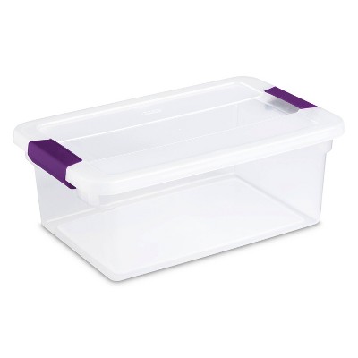
Read reviews and buy Sterilite 15qt Clear View Storage Bin with Latch Purple at Target. Choose from contactless Same Day Delivery, Drive Up and more.
My profile picture is actually from a robot I had built some time ago, in a robotics class in a summer camp: https://www.hackster.io/shurik179/gps-wifi-rover-27ecd7

Hackster.io
An outdoor rover, capable of autonomous navigation (using GPS and sonar sensors) or controlled over WiFi. By Alexander Kirillov.
BTW, you realize that your mecanum wheels are mounted in wrong orientation?
low cave
looks liek the recommended -13% in that code was teh problem
not enough power to the motor
mossy olive
native cipher
BTW, you realize that your mecanum wheels are mounted in wrong orientation?
I saw your message, there a not screwed in yet. But they have right ans left indications and I fell like I followed the instruction correctly. I’ll have more thorough look as soon as I find the appropriate controller
mossy olive
Understood, I have changed them. Thanks for the link it will help me a lot
If I may, would you like have any good documentation on hall sensor motors?
 undone basin
@low cave I found that the yellow 1:48 TT gearmotor needs the PWM equivalent of at least 2v to start spinning reliably due to the Crickit's default PWM frequency: 40% throttle. A blue 1:90 TT gearmotor has a lower spin threshold.
low cave
undone basin
<@!643468140247908353> I found that the yellow 1:48 TT gearmotor needs the PWM e...
Thanks for that reply. I just went with the one linked to from the tutorial on learn.adafruit - but that's a good thing to know.
maiden pebble
Hi all, I'm testing out the new BNO085 orientation sensor. I want to convert the sensor output to Euler angles and it's working pretty good, but I've got an issue with the pitch. Instead of giving me 360 degrees of rotation I get a measurement of 90 degrees when it's pointed straight up and -90 degrees when it's pointed straight down. The problem is if I tilt it clockwise or counter clockwise from either of those positions it gives the same number.
For example if I have it pointed straight up (90 deg) and tilt it clockwise 15 degrees, I'm getting 75 degrees. Then if I put it back straight up (90 degrees) and do 15 degrees COUNTER-clockwise I still get 75 degrees, when I expect I should get 105 degrees from one of them.
I don't grok the quaternion math so I had to get the conversion code from someone else.
Here is the code I'm using to convert to Euler angles (in CircuitPython)
Any ideas?
def quaternionToEuler(qw,qx,qy,qz):
    roll  = math.atan2(2.0 * (qw * qx + qy * qz), qw * qw - qx * qx - qy * qy + qz * qz)
    pitch = -math.asin(2.0 * (qx * qz - qw * qy))
    yaw   = math.atan2(2.0 * (qx * qy + qw * qz), qw * qw + qx * qx - qy * qy - qz * qz)
    pitch *= 180.0 / math.pi
    yaw   *= 180.0 / math.pi
    if yaw < 0: yaw   += 360.0  # Ensure yaw stays between 0 and 360
    roll  *= 180.0 / math.pi
    return EulerOrientation(roll=roll,pitch=pitch,yaw=yaw)
 lone skiff
I think that's correct. For the "105-degree" case, the Euler angles would be 75 degrees of pitch, but the yaw would be 180 degrees different, i.e. it's pitching down from vertical but turned around in the other heading direction.
maiden pebble
lone skiff
I think that's correct. For the "105-degree" case, the Euler angles would be 75 ...
Ahh! Thank you!
 cobalt yarrow
Hello... I haven't done robotics in a long time, since I was a kid, but I am trying some stuff out again lately. I want to make a simple wind direction sensor without buying an expensive weather station wind vane setup. If I was doing it in lego I'd use one of these rotation sensors
Whats the equivalent of this in non-lego parlance? A rotary encoder with very very low detent force?
Thank you for any advice on this 🙂
primal shell
Yes, basically a rotary encoder. They are made using various technologies (optical, magnetic, etc.).
 signal seal
You might be able to hook up a magnetometer to a shaft. That'll give you heading (i.e. direction)
misty charm
for heading, you'll want to pay attention to the orientation of the poles of the magnet, and use an analog hall effect sensor chip
idle grove
 cyan horizon
Anyone here think they could help me with an animatronics project?
is there any way of controlling servos with MIDI? I'm building what is essentially a "Big Mouth Billy Bass" style wall mount
My plan is to have an arcade button activate a character to play a skit show featuring music
To get the animation right I want to "keyframe" the servos to the audio
There will be 2 servos
one for the jaw and one for the arm of the character
The character will be flat in the final thing
I have a VAST variety of parts
But right now I'm either going to use a Crickit hat with a raspberry pi
or an arduino
I have no idea how to get the "guts" of this working
 wet mortar
Helllo. First is connected like on the picture except ESP32-S2 instead of uno and no 35 V battery and righttopmost pin on on L293D is connected to 5V. This way everything works. I can drive car and I can control servo.
Then I connect the top rightmost pin from L293D to pwm PIN. Now the engine does not turn on.
So I decide to upgrade the power and I connect the 10S battery with voltage around 35V. There is a bang and a bad smell and after that my ESP32-S2 doesnt work anymore
What did I do wrong? L293D is triple piggyback.
primal shell
@cyan horizon Yes, it's possible. However, I don't think MIDI is necessary, and may make things more complicated than they need to be.
@wet mortar Your diagram does not match your description. If you did indeed hook a 35V power source to the "top rightmost" in as in your diagram, that would be pin 9 (outputs 3 and 4 enable), which would be incorrect and cause damage.
cyan horizon
@primal shell I mean whatever the easiest method is for key framing the movements will work
However I can control and record the movements to the audio
wet mortar
@primal shell Pin 9 is connected to PWM on board. 35v battery connected to pin 8 vcc2
 proven lotus
well theres your problem i'm wrong dont listen to me
the board is meant to be powered with 3.3v (maybe 5 depending on the pin) and you gave it 35
if you want to power the controller from the battery you need some kind of voltage regulator; there are a bunch of cheap ones you can get and solder to on Amazon
wet mortar
I was thinking the 5V is powering the controller and the 35V powers the motor
the l293d H gate just let the 35V go to motor
proven lotus
The only thing I can think of is that you accidentally connected the esp to motor voltage
is it possible you connected the wrong pins?
wet mortar
I double check and the diagram seems right. It is my first project ever with breadboards so I just wonder if I did some obvious mistake.
primal shell
@cyan horizon For key framing, I'd just store the positions: that's the easy part. For in-betweening, I'd user linear interpolation. That can be with floating point math easily enough with linear equations, or if you need more speed, a Bresenham algorithm. Code to run things like plotters, CNC machines, and robotic arms uses a similar approach for coördinated motion (which is what I'm guessing you're looking for here).
cyan horizon
I have literally no idea how to do any of that
And I am not a coder
Plus I’m not good at math
 grim cove
@wet mortar What's up with the soldering on the L293D?
wet mortar
@grim cove matth L293D can deliver 600mA and piggybacking three of them and solder the legs together will give up to 3 times more current and it is closer to what the motor is rated for.
grim cove
Ah ok 🙂
 hazy saffron
can i drive a 4 pin stepper motor with a 5pin uln2003 driver?
 exotic prawn
My goal is to detect how far away from the camera something is.
I have two approaches. For context, both approaches will allow the camera's pitch and yaw to change via gimbals.
- Have two cameras, each with a motor and end-stops for those motors OR one motor, a couple of springs, and a string (for minor yaw changes, from zero to 80 degrees inward). In the programming, one camera will be the dominant camera. To determine object similarity, I will use keypoint detection with OpenCV. When the program wants to determine how far away the object is (which is in the middle of the dominant cameras' vision), the next objective will be for the non-dominant camera to adjust so that the detected object is centered in that cameras' vision via keypoint deltas.
- Use one camera and one laser. When the program wants to determine how far away the object is (which is in the middle of the cameras' vision), the laser will turn on and span its' pitch from pointing just past the camera to where the camera is pointing (""horizon"") (the distance of the laser to the camera is given). Once the laser appears on the edge of the cameras' vision, the program will know that the laser needs to stop once it red dot reaches the center of the screen. I am not sure how I am going to detect a red dot, but I reckon it isn't difficult to achieve with OpenCV.
The only concern I have with #2 is safety. I don't want to blind anybody... One safety measure I could take is to have the laser blink and use it conservatively. I am guessing it wouldn't last any longer than a second under normal circumstances.
Any thoughts on this? Would there be any better methods I can use? I have seen some stereo cameras online (such as Intel RealSense), but those cost a lot.
The first idea would look kind of like this, just way lower budget: https://s1.www.theimagingsource.com/newsletter-2.0/20171004/img/hero/hero_1.png
 lone skiff
What sort of distance ranges , object size, and accuracy do you need? An easy variant of the laser idea is to have a fixed laser pointing parallel to the camera at some horizontal offset (smaller than the object you want to detect), and then you can compute the distance by seeing how far away from the center of the frame the red dot is.
Sometimes people use laser line projectors rather than a dot, in order to make it more eye-safe and to get a whole distance profile instead of just a single measurement.
exotic prawn
then you can compute the distance by seeing how far away from the center of the frame the red dot is
wow, I have never thought of that haha
less moving parts
@lone skiff I am ultimately going to make a robot that detects raccoons or deer getting too close to the garden and spraying them with water. I don't have a solid blueprint or anything, but in my head I am guessing it will start out to be under a foot wide
couple feet tall maybe
the top will have a "weatherproof" dome to protect the electronics, and below will be the hose
the whole thing will be able to rotate -180 to 180 with endstops
lone skiff
Hahaha, awesome...
exotic prawn
At first I was going to make it out of wood, but now I think it would be better to 3d-print some of the parts out. The base and support beams will probably be wood, but the parts with electronics and what not will be printed out
exotic prawn
Finally got the equation: https://www.desmos.com/calculator/wn1wsdog2x
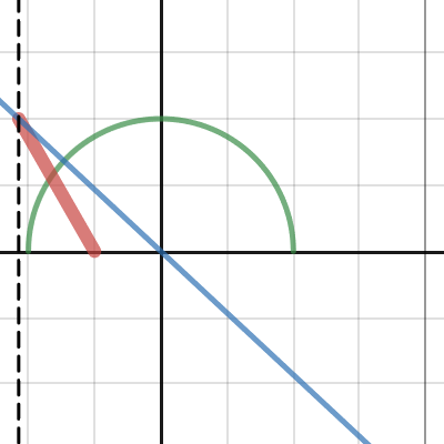
Desmos
thank you for the inspiration
turbid inlet
omg what's up with all of these crazy diagrams?
simplify your presentation unless all 5 x 28.8 boxes are not the same
idle grove
Ok
 gritty fractal
I just came across the post from Oct about an esp32s2 based Clue. Any updates since then or some where to sign up for news? Looks like a perfect upgrade for my sons micro:bit based robot.
twin cove
gritty fractal
I just came across the post from Oct about an esp32s2 based Clue. Any updates s...
Not yet, but I believe that some prototype boards were shown off in the last week or two. Depending on how the testing goes, that will determine timeline. But, it's much closer than it was!
gritty fractal
@Hugo Thanks, I was getting close to picking up a metro and motor shield but the Clue looks like it could plug into the existing chassis and provide some new functionality as well.
primal shell
@hazy saffron Not very well, the 4-wire steppers are "bipolar" and the ULN2003 is "unipolar".
exotic prawn
Let's say I had a robotic head that can spin 360 degrees and keep going forever, no endstops. How would I get power to it? Is it possible?
Would there need to be "rails" to deliver the power?
Pantograph
primal shell
You could use a slip ring like https://www.adafruit.com/product/736, or a double-twisted ribbon cable, inductive coupling, capacitive coupling, optical coupling, a generator, etc.
Slip rings and inductive coupling are probably easiest. https://www.adafruit.com/product/1407

The squarish board with two chips on it is the transmitter (power with 9V). The longer board is the output and you can connect that to the part of your project that needs ...
exotic prawn
Thx
idle grove
Hey weird question Anyone know spots dimensions
misty charm
https://shop.bostondynamics.com/spot - click on "Specs" tab
spot
idle grove
Anyone see anything wrong other than balance
 barren sky
I have to assume these are all going into one application with only one output connector for all. If so, why separate bms for each battery vs. solid state multi controller? It can regulate up to 20 different cells and balance them as you go (and nowadays.. possibly even cheaper if you're buying the bms for this diagram). As for wiring, I would parralel all inputs to bms then add the charge control monitor wires to the batteries. Sorry I hope I made sense, I'm super tired and overworked nowadays.
@exotic prawn yes just like a steering wheel clock spring in a car. either a brushed or brushless contact would be setup for each contact required. unless! You got crafty, wireless power transmission depending on gap to travel, bluetooth power transfer you could even use a pair of wireless charging pucks as digital potentiometers to gauge movement and speed. Nothing like a spinning android head to gain interest...lol
I have an AI I've developed after 10 years and am looking to develop a suitable body for it as a next logical step. Anyone in here want to help out with an unusual project from time to time? In this trying time there would be no faster acception of robotic humonids, gynoids etc. With all the isolation and fears and future fears. These can be used by millions, from retirement homes for consoling and engaging the elderly to a parent needing a nanny for a few hours. There are some companies that have half a idea but don't see the bigger picture and there's the ones that do, won't produce it and when they do, it will be out of reach for most consumers. Am I crazy?
lone skiff
A little bit crazy. 😉 If you have an android-level AI, it would be far easier to find non-robotic uses in the software realm to commercialize it first. Tackling a real home helper robot as a hobby project is a lot to bite off, as you probably know.
exotic prawn
barren sky
I have an AI I've developed after 10 years and am looking to develop a suitable ...
Maybe make your ideal robot in some kind of 3d simulation first?
and implement the api for the virtual bot
I was hoping boston dynamics would make a "Virtual Spot" that people can run on their computers in order to learn how to control spot without having to spend thousands
 sly sand
@barren sky My guess is that no mobile AI will exist as such: there'll be a radio (wireless) link to the 'real' AI if there even is one.
aka slab A.I.
telepresence seems a lot more likely.
(pretty much what military drones are, now)
barren sky
Hello nis, already have them virtual, they've been evolving over the course of the last year in a private beta. There will still be further coding required once hardware is considered, but they are stable and evolving at a steady pace in accordance to each beta users experiences with it. As for function, yes wireless, 5g/wifi capable and will have a 'dumb' mode for when offline where it can only draw basics and what it's stored locally on ssd (which is still a considerable amount of data on its surroundings but is based on time running.)
sly sand
Lex Fridman seems pretty conservative about estimating the future of AGI. ;)
The look on his face when he says 'its a hard problem' is informative. ;)
misty charm
@barren sky do you have any more information (website, video, etc) about this AI you've been working on?
barren sky
Hello Jon,
Unfortunately only those brought in on the project under nda have any access to core materials. I am not at liberty to get too deep into heuristics and underpinnings of the code in public eyes. But safe to say, if you're interested and want to know more, some background on what you feel you can contribute to the project, may allow me to give you more details, and possibly allow you access to a beta via nda. We have done recruiting, job fairs, schools looking for bright talent. So far I feel I am barking up the wrong tree, hence why now I'm opening up to the internet brains for possibilities as I have found some of the most brilliant minds don't have degrees at all. I want to find people that have experience over educational background on paper. Theory doesn't necessarily outweigh productivity, problem solving abilities and outside the box thinking.
primal shell
Most of the PIR sensors I've seen are digital, they provide a pulse when motion is detected.
 soft radish
Just two questions about wires and fuses: would 18awg wire be fine for 12v 5a: only for at most 3m (e.g. https://www.amazon.co.uk/TUOFENG-Electrical-Different-Temperature-Resistance/dp/B07G744V5Z/ ) or would it be a bit unnecessary (so I can just use 22awg)? Also, if I have 3 motors wired in parallel, should I give them each a fuse or just use one fuse between the motors and the power supply? Thanks.
 dry smelt
Is there an easy way or 3d print to adapt these wheels (https://www.sparkfun.com/products/13259) to attach to a servo?
native cipher
@soft radish you do not want to use 22AWG for 5A current. Best case scenario, you will just get noticeable voltage drop (an online calculator estimates voltage drop of 1.6 V under these conditions); worst case scenario, your wires will overheat.
Get 18AWG - you can get cheap one if you want (which wouldn't be silicone insulated)
@dry smelt would any of the wheels on this page, specifically designed to be mounted on servos, work for you?
https://www.servocity.com/servo-mount-wheels/
dry smelt
@native cipher OMG YES THANK YOU!!!!
native cipher
just make sure to match the spline - most servos use 25T spline, some use 24T spline...
dry smelt
Already checked the data sheet, much thanks again!!
dry smelt
I made a 4 wheel car with basic dc motors and set them to max speed and it drifted to the left. Whats the best way to make sure every thing is in sync?
I don't think it is a code issue...
native cipher
This is normal. No two motors are exactly identical, which explains veering to the side
To fix that, you can either use motor encoders, or imu/gyro for course correction.
forest cipher
🙂
dry smelt
thats an awesome board
native cipher
Thanks
soft radish
native cipher
<@!515966234643136512> you do not want to use 22AWG for 5A current. Best case sc...
thanks
What about the fuses question: if I have 3 motors wired in parallel, should I give them each a fuse or just use one fuse between the motors and the power supply? Thanks.
native cipher
I normally either do not use fuses at all, or use a single fuse per power supply - just to deal with shorts
soft radish
ok, thanks
 cloud venture
Uh. Anything between nothing and fire. Generally the cheaper the converter the more likely to be fire.
You'd have to know what the chip doing the switching was to know for sure.
(And possibly external FETs)
proven lotus
cloud venture
Uh. Anything between nothing and fire. Generally the cheaper the converter the m...
which is why i strongly recommend buying wildly overspecced buck converters if they're cheap
cloud venture
Just don't buy no-name brand Amazon ones if it matters.
@idle grove What is your input/output voltages?
idle grove
33.6v
cloud venture
Need all 12 of those amps?
idle grove
24v
cloud venture
What are you trying to do with this 24v?
idle grove
With 8 servos and 1 jetson nano and 3 arduino mega
cloud venture
So you are trying to put something after the BMS, Right?
idle grove
Affirm
4 24v motors going in this with this config don’t judge me of the schematic it’s @empty oasis
cloud venture
So this digikey search has a bunch of DC/DC converters that output 24v.
You need to figure out how much power you need for your servos/jetson to know which one to choose.
idle grove
Each one is 5v
cloud venture
Do you mean 5W? (five watts)
idle grove
The arduino jeston and servos are 5v so I’m useing a 2nd buck
Actually the motors can go up to a 10s
 empty oasis
idle grove
4 24v motors going in this with this config don’t judge me of the schematic it’s...
empty oasis
idle grove
4 24v motors going in this with this config don’t judge me of the schematic it’s...
Wow, I've been reported to the messy schematic police
idle grove


@empty oasis but do you see a problem with slightly overvolting a buck
It’s guna be from 33.6 down to 5v
primal shell
Fairly high risk of the converter failing, and passing the entire input voltage to the output.
idle grove
Ya
 sterile silo
Hi, has anyone gotten & used the RageBridge 2 (https://www.adafruit.com/product/3567) for any of your larger robotics projects? Thoughts, impressions etc?
 plush topaz
@idle grove you could consider only charging your li-ion cells to 4.0V and you would be at the 32V spec ?
native cipher
@sterile silo not yet.
I have seen projects using RoboClaw controllers, they are quite popular and reliable (e.g. https://www.servocity.com/roboclaw-2x30a-motor-controller/); unlike the RageBridge, they also give you closed loop control using encoder feedback. Is there some reason you want to choose RageBridge?
sterile silo
Na, no particular reason other then it's being sold by Adafruit, & I trust Lymor's high standards. The Roboclaw looks cool, but it'd be way too week for my project. My fuses don't even pop till 40Amp, I'd b burning those all day long. I'm working with power chair motors, & looking to carry 2-300 lbs. (a full grown adult)
@native cipher
native cipher
Roboclaw also has higher current version: https://www.servocity.com/roboclaw-2x60a-motor-controller/

ServoCity
sterile silo
Do u sell these or something?
native cipher
me? no, I am just a user on this discord. Not affiliated with adafruit or servocity
sterile silo
Ah gotcha. but na, I'm already choosing between the Sabortooth or the ragebridge, I'm not going to add another to the research list.
Thanks anyways tho.
 acoustic scarab
Good morning! I was wondering if someone could help me with a boost converter? I am using the LM2623 Ev module. I am using a 1.3V input and am trying to get a 5V output right now. I am trying to get a 3.3v Output but have a slight clue about how to do that. Any help would be appreciated.
 next palm
acoustic scarab
Good morning! I was wondering if someone could help me with a boost converter? I...
acoustic scarab
next palm
acoustic scarab
Good morning! I was wondering if someone could help me with a boost converter? I...
acoustic scarab
With that IC yes, but I meant this board: https://www.ti.com/tool/LM2623EV
View the TI LM2623EV Evaluation board description, features, development resources and supporting documentation and start designing.
acoustic scarab
next palm
this one? https://www.ti.com/lit/ds/symlink/lm2623.pdf
I was going to desolder the 300k resistor and put a 168k resistor. I picked that resistor from the equation found in the data sheet,
next palm
That looks right
acoustic scarab
next palm
That looks right
Alright cool. Thank you!
 chrome vigil
Anyone know the approximate power draw of these micro servos (https://www.adafruit.com/product/169)?
undone basin
chrome vigil
Anyone know the approximate power draw of these micro servos (https://www.adafru...
Haven't measured it in operation, but here's a clip from the data sheet for the internal DC motor:
 chrome vigil
undone basin
Haven't measured it in operation, but here's a clip from the data sheet for the ...
chrome vigil
undone basin
Haven't measured it in operation, but here's a clip from the data sheet for the ...
alright cool, thanks! Do you think i'd be fine using a 1 Amp power supply like the MiniBoost?
undone basin
Not certain. It looks like the starting current can be as high as 1.2A but that's a short duration draw. Sometimes adding an electrolytic capacitor across the power source can help to supply peak current situations. Only one servo?

We like capacitors so much we made a kids show about them. They're super handy and it's really helpful to have a variety lying around to pick and choose from.This is a 10 ...
chrome vigil
yeah, i'd only be using one
trying to push a button on the side of a handheld radio
undone basin
The chip used in the MiniBoost is rated for higher current, but the inductor used in this particular design may not. Good news is that the chip will automatically go into a protective mode if excess current draw causes its temperature to increase.
undone basin
It's up to you. Given the unverified data and if an electrolytic capacitor is placed across the MiniBoost's output (note the cap's polarity markings), it'll likely work okay.
^Stall current could be higher than the starting current, so be certain that your mechanical linkage can't get stuck.
chrome vigil
alright then, I think I'll just use a beefier 5V regulator. thanks!
 remote eagle
I don't know if I should post here or in projects. I am using cpx and Crickits with HS students as a way of introducing engineering and robotics. We are using tt-motors and 4.5V power through AA battery packs. What is happening is the motors turn on but don't proceed through the code. The cpx responds. I know this as the program I created changes the light color. Pressing the A button runs the program and changes the led color as well as the program proceeds. Pressing B should shut the motors off but also turns the lights red. The colors change but the motors do not turn off. Running 1 motor on tje bench works great.
Hitting the reset on the crickit can allow the program to work at times. Would I be better off running a second battery pack for the cpx? My guess is that the motors are causing a voltage drop and then the Crickit freezes up and loses connection to the cpx.
native cipher
I'd test it with separate power supplies (keeping the grounds connected, of course). If it helps, this is indeed the problem. If not the problem is elsewhere - most likely the code
 west wing
What a cutie pie! Or is it... a QT Py? This diminutive dev board comes with our favorite lil chip, the SAMD21 (as made famous in our GEMMA M0 and Trinket M0 boards).For a limited time: only ...
west wing
west wing
https://www.adafruit.com/qtpy
Does anyone know how many sensors you can connect to this in series?
 modern pulsar
@west wing Depends on what programming language, and your limiting factor is more likely to be code size than it is how many you can connect. It is my understanding that you can connect as many as you want as long as they have different I2C addresses. But there is limited space on the QT Py (unless you add a flash chip to the back), so for example in CircuitPython, you might be limited to one or two sensors depending on the library size.
I had one sensor and the onboard NeoPixel working together and ran into memory limitations if I wasn't careful.
west wing
modern pulsar
<@!494285629404741633> Depends on what programming language, and your limiting f...
I flashed it as an arduino and I have 2 sensors connected and it says it is only taking up 5% of the space so I could theoretically connect like 20
modern pulsar
Basically as long as the addresses don't clash, you should be good.
Keep adding until it fails 🙂
west wing
modern pulsar
Basically as long as the addresses don't clash, you should be good.
Thank you for your expertise 🙂
modern pulsar
You're welcome!
 harsh hill
@west wing you may also run into issues with the total length of the cables which adds resistance and capacitance. It’s more likely to run into running out of program space, ram or overlapping i2c addresses before that though. If it does happen something like this might help though https://www.adafruit.com/product/4756.
west wing
harsh hill
<@494285629404741633> you may also run into issues with the total length of the ...
Thank you !
harsh hill
All good. I remember reading that i2c isn’t really designed to run long distances over cables so stemma qt is pushing it to the limit. Most of the time it’s fine but when you have many devices it can break. You can also get breakout boards which turn one connector into many which might also help as the length from the microcontroller to any of the devices will be lower as it doesn’t need to go though as many hops to reach it.
west wing
I think I am gonna cap it at 6 or 8 per QT PY so it doesn't break
 austere pine
Hi!! These motors could be controlled with a joystick right? https://www.adafruit.com/product/4416?gclid=EAIaIQobChMI8fiQ4MS77wIVZT2tBh1iugomEAQYAiABEgLj6vD_BwE
The first step in a robotics project is to get a motor spinning. Once you've done that you quickly learn that not all motors go the same speed, even if they are the same part number! ...
native cipher
These motors are normally controlled by a motor driver/shield (such as https://www.adafruit.com/product/1438) which in turn is controlled by a microcontroller. Yes, you can connect a joystick to a microcontroller so it reads the joystick input and converts it into motor power.
 boreal talon
This robot / art channel just popped up on my youTube suggestions. Only a few 1 minute videos. The motion and design of the servos are next level. well worth a quick look. 🙂 https://www.youtube.com/c/OleksandrStepanenko

YouTube
Oleksandr Stepanenko, Ph.D.
• Precision robotics
• Industrial robot calibration
• Mechanical design
• Lab automation
• Metrology
• Parallel robot design
• Precision machining
• Video production
• Product photography
 scenic comet
hey yall, had a question about what size screws i'll need to mount my servos to this metal chassis? It seems like mounting holes on the chassis are at like 2.5M but the holes in the servos themselves are smaller. does anyone know what size screws i'll need for the standard mini servos? are they 2M screws? i got the 2.5 and 3M nylon screw packs but none of them fit and adafruit doesn't carry them in 2M

OK the name is a little...utilitarian? But this Anodized Aluminum Metal Chasis for a Mini Robot Rover does exactly what it says. You can build a very sturdy (and quite handsome!) little ...
primal shell
There's some useful (but non metric) info here https://www.rtlfasteners.com/RC/d.html
native cipher
@scenic comet it seems to be designed for use with micro (not mini!) servos like this one: https://www.adafruit.com/product/2442
and according to drawing in datasheet, the mounting holes are 2mm diameter. So, M2 screws should work.
You can get M2 screws, e.g., from McMaster-Carr
Need to make a tiny robot? This little micro servo rotates 360 degrees fully forward or backwards, instead of moving to a single position. You can use any servo code, hardware or library to ...
 manic depot
Hi I have this chasis with MotorShield V2 on an ItsyBitsy M4. Works fine but does not move streight for more than one feet. Does anyone have a cheep chasis wich does roll reliable ?
 native cipher
if you want to move straight, you need some way of correcting drift - either using IMU or motor encoders. Without some kind of feedback, there is no way to avoid running in circles.
You can get a chassis with motor encoders and write your own code for using encoder feedback to correct turning.
<shameless self-promotion>problems like this were exactly the reason we designed our own robot control board which incorporates IMU: https://www.crowdsupply.com/alexander-kirillov/roverwing </shamless self-promotion>

without using IMU/encoders, the best you can do is experiment and try to correct motor differences by trial and error: if you see that the robot always veers to teh right, slightly increase power to right motor. But you can't completely get rid of drift this way, just make it smaller.
manic depot
The imu does not help with such a gab. I realy would nee a better chasis thought
native cipher
IMU certainly helps moving straight - if used correctly
but it requires use of proper data fusion to remove the noise
manic depot
Your plattform look's great in that Perspektive ! I just don't like everything is glued so much together
austere pine
Hi! Does anyone know what wires/connectors this DC motor is using? I am trying to buy more of it https://www.adafruit.com/product/4416
The first step in a robotics project is to get a motor spinning. Once you've done that you quickly learn that not all motors go the same speed, even if they are the same part number! ...
proven lotus
Looks like a JST connector to me: https://www.adafruit.com/product/4029 has some good images to compare with.

This cable will let you turn a JST PH 4-pin cable port into 4 individual wires with grippy mini alligator clips. We're carrying these to match up with any of our boards or breakouts with ...
That one doesn't have as many wires coming out, but it seems to be the same style.
austere pine
proven lotus
Looks like a JST connector to me: https://www.adafruit.com/product/4029 has some...
Thank you!! Do you know if the wires are 28AWG
🤔
proven lotus
I don't know for certain, but the wires on the Amazon link look about the same size (edit: relative to the connector) compared to the ones on the Adafruit motor, so I'd bet on yes
native cipher
@austere pine the amazon link you sent is JST GH connectors.
What @proven lotus suggested is JST PH connectors.
These are different and incompatible connectors.
I am not sure which ones the motor actually uses, but it does look likely to be JST PH, not GH
Compare with: https://www.jst-mfg.com/product/detail_e.php?series=199
and 28AWG is too thin to be used for power wires, even for such a small motor. I'd suggest 24AWG
proven lotus
I wasnt aware of the different types of JST connectors; thank you for the info!
native cipher
oh boy.. there are several dozens of them
it is even worse for "Molex connectors"
proven lotus
No wonder I could never tell what type of connector was on a pcb! I thought every one had a different name!
native cipher
Most common JST are JST PH (2mm pitch - used both for power - e.g. Adafruit uses JST PH 2-pin for LiPo battery connector - and signal), JST GH (1.25 mm pitch), and JST SH (1mm pitch), used for Qwiic/StemmaQT
it is a challenge to determine the connector type, indeed
e.g. in the world of RC cars and toys, it is common to say "battery with JST connector" - which actually is JST RCY connector, but they never say that
actually... I looked at the motor again, and it does seem more like JST GH, not PH
 granite roost

ive had these lipos in storage for years. I nevrr used them... right one is slightly puffed and I'm concerned. I should dispose of it, right?
the one on the left has a very, very minor puff... I cant even tell of it was like that from the stsrt.
 twin cove
In all honestly, those are both looking passed the point of puffy safety for me
granite roost
😩
twin cove
You're free to try them if you're comfortable doing so. I was stating my opinion
granite roost
I agree with you :)
twin cove
Now to find somewhere to store them safely until you find somewhere to dispose of them safely!
That's always been my problem
granite roost
any good resources on lipo safety checks? like measuring the voltage, general inspection, etc
proven lotus
twin cove
Now to find somewhere to store them safely until you find somewhere to dispose o...
to the explosive containment pie dish!
twin cove
proven lotus
to the explosive containment pie dish!
I was thinking that, but couldn't recall the exact phrasing
proven lotus
clive is a hero to us all
twin cove
lol, true
I can also never remember the exact reasoning for using purple cables or pink parts, etc. Something about dying and shame maybe?
proven lotus
I don't remember that either, I'm pretty sure its just his favorite color though
man really likes the color pink
granite roost
twin cove
In all honestly, those are both looking passed the point of puffy safety for me
I tested their voltage and the one that's really puffed up is at 7.48V (normal would be 11.1V) so that's really bad. The other one, though, is at 11.25V; and I don't feel it's puffed up at all (I haven't managed them in years so I can't really tell what was the "normal" state. But seems like this second one should be fine. What do you think?
proven lotus
The frustrating thing is that its very difficult to know for sure whether a battery is safe; this battery seems like it is based on what you've said, but I wouldn't trust it as much as a brand new one.
Use at your own risk, basically.
twin cove
First, a disclaimer!: I'm not an EE or all that knowledgeable in electronics, so all this is personal opinion.
Obviously #1 is just bad, and any usage aside from disposal is out.
For #2, if you feel that it actually isn't puffed, and that it's safe, then it's your call. If you got them at the same time/place, and they've been stored together, my concern with #2 is why is that one "good" when #1 isn't? If they weren't bought at the same time, or have different lot codes/numbers (if they have those? I really don't know), then it might be fine.
My final personal selection criteria for #2 is: How much is the cost of a new one (in time, delays and money) versus any chance of using it?
proven lotus
These things are like glass; its really hard to tell exactly when they'll fail, even if they're brand new. They might be more durable than you expect, or less. My best advice is to test how well this battery discharges, e.g. if it has kept its C rating, and see if it goes puffy. If it doesn't, recharge it and you're good to go. If it does, well, don't.
As with all batteries, keep an eye on it (particularly while testing) and know what to do if it puffs or catches fire.
sly sand
Even your doctor will look at you sternly when you say 'I read on the Internet that ...'
There's no reason to make any decision for convenience and against safety.
Those should be considered as emergencies, only.
If life and limb is not yet at stake, don't put them at risk. ;)
granite roost
twin cove
First, a disclaimer!: I'm not an EE or all that knowledgeable in electronics, s...
thanks! I appreciate everyone's feedback 🙂 They are different brands so this might explain why one failed and the other one didn't
 twin cove
granite roost
thanks! I appreciate everyone's feedback 🙂 They are different brands so this mi...
twin cove
granite roost
thanks! I appreciate everyone's feedback 🙂 They are different brands so this mi...
I think you can tell from all of the responses you've received that, ultimately, what every really wants is for you to be safe first and foremost!
austere pine
Hello!! Are there any extensions for this type of cable?
 primal shell
It's possible, but first you'd need to figure out what kind of connector that is.
grim cove
Plain old wire and heatshrink 😄
proven lotus
when in doubt, get the soldering iron out
austere pine
@primal shell Hello do you think these would work? https://www.amazon.com/ACTOO-Connector-Female-Terminal-Adapter/dp/B07YWHCPW5/ref=sr_1_11?crid=128YLHXZE4WDS&dchild=1&keywords=6+pin+connector&qid=1617058691&sprefix=6+pin+%2Caps%2C235&sr=8-11
 spark sun
@austere pine You could splice those in and use them, but it looks like these are a closer match. https://www.amazon.com/gp/product/B07F8JSTV9/ref=ppx_yo_dt_b_asin_title_o02_s00?ie=UTF8&psc=1
austere pine
spark sun
<@!224034953841606657> You could splice those in and use them, but it looks like...
Thank you so much!! I will purchase these and see if they fit. Can I just stick those wire ends into the connector?
spark sun
austere pine
Thank you so much!! I will purchase these and see if they fit. Can I just stick ...
The ends of the wires will need to be soldered to the connectors. They do it that way to give the user more freedom on how they are used.
 still osprey
I have the motor shield v2.3 and already soldered the packaged headers on to it to put on an uno, but I want to put a bt addon to it. can I use those secondary rows below it? or is it better to just solder on top of the header pins?
primal shell
I don't think the inner rows would line up, unfortunately
idle grove
Intel® RealSense™ Depth Camera D435i
Could I use the IMU for SLAM or V-SLAM
lone skiff
idle grove
Intel® RealSense™ Depth Camera D435i
Could I use the IMU for SLAM or V-SLAM
I'm not quite sure what you're asking. The camera is basically already doing SLAM in order to provide the IMU data.
idle grove
Ya I didn’t say it in the best way i copied it from a different server and it was like midnight but anyway I ment to track it self in a 3d space for autonomous walking
lone skiff
I haven't used it myself, but yes, I think it would be good for that.
idle grove
Ok I knew the tracking cameras could do that but I was unsure about that camera
austere pine
Anyone know if this could be made compatible with a geared dc motor with an encoder? https://images-na.ssl-images-amazon.com/images/I/71hIzRVH8AL._AC_SL1200_.jpg

or only servo?
idle grove
To my knowledge you can by connecting the encounter to the motor shaft an with some simple math you probably could find what position causes the griped to go whare
 pseudo moss
does anyone have experience with the stepper driver feather wing? if so, what was your experience? I'm getting strange results out of mine and I can't seem to get much speed out of it
primal shell
It has worked fine for me but I'll point out that stepper motors basically trade off speed for accuracy: they're not useful for rapid rotation.
pseudo moss
Ah I see, I noticed at around 10 rpm I get okay rotations, but at 50 I get a lot of jitter and really high heat. Maybe I should swap to encoded DC motors for my actuators
How do people run planetary gearboxes with steppers tho efficiently if they can’t move fast?
native cipher
Normally you use DC motors with planetary gearboxes
What RPM and torque do you need?
pseudo moss
I'm just running some tests right now so I only want enough to move the gears. I've seen videos of people building robotic arms with steppers which is my ultimate goal
@native cipher
like I cant get that stereotypical whine
idle grove
8192 CPR ENCODER WITH CABLE can you use that encoder with a Jetson nano directly instead of though a o drive
acoustic scarab
Hey guys, I’m having some issues getting this mosfet to work. It’s an N-type mosfet, and the two wires coming from the right of the motor is my power supply. I can’t get the gate the motor to spin. I’m assuming from bottom to top it’s Gate Drain then source. It’s a P30N06LE. I was able to get the gate working before but it won’t budge anymore. I tried using a new mosfet and a new motor but I think it’s my wiring? I got the same voltage from the power supply connected to the motor and connected it to the gate pin, the bottom most pin in the photo, but it still wouldn’t budge. Can someone check my wiring? I feel like this should be something easy but it’s not working haha.
 primal shell
The gate does not appear to be connected. Note that to turn on the gate, you need to supply a voltage between the gate and source (so generally there would be two wires connected to the source, one from your power supply return and one from your gate signal source).
 mighty ridge
So I'm trying to use a Crickit's "Signal" pins as a Pin in CircuitPython, but that's not a thing, apparently. Any workaround for that? I'm trying to use the adafruit_hcsr04 library.
mighty ridge
remote eagle
I don't know if I should post here or in projects. I am using cpx and Crickits w...
Did you update the firmware on the Crickit?
mighty ridge
mighty ridge
So I'm trying to use a Crickit's "Signal" pins as a `Pin` in CircuitPython, but ...
just found this: https://github.com/adafruit/Adafruit_CircuitPython_HCSR04/issues/24 darnit

GitHub
It seems that it's not possible to connect the HC-SR04 to Crickit using its signal I/O pins instead of connecting it directly to the micro-controller. Apparently this library requires the t...
remote eagle
Thanks for the info. And yes, updating the firmware seems to help.
 timber island
Hello! I found a circuit (from 1979) but need something that delivers the power
I need +12v, -12v, +5v and 0v
what is the easiest way to get this/
(its for an oscillating circuit so there shouldn't be too much noise in it)
primal shell
Radio Snack used to sell the old ColecoVision power supplies that offered those voltages. Some PC power supplies do too (but have some limitations). There's also a range of hobby supplies like that. It does depend somewhat on how much current is required.
 light ibex
Hello enginerds. quick question. I am trying to code my arduino uno to control a robotic arm (OWI robot arm). I wanted to use potentiometers to have closed loop feedback however I cannot find where to wire them to my adafruit v2.3 motorshield. I see that old photos of the version 1 motoshields have analogue ports, but I do not see them on mine. Can someone please show me where to connect the sensors? Also, I am trying to rewrite code for the OWI robot arm as to not require sensors - I want to set the motion parameters manually. Can anybody help direct me in learning the code?
here is a photo... Thanks!
 primal shell
You should be able to use the Arduino analog input pins to read the potentiometer values
light ibex
I don't know where to put in the other two wires (input to analog in, but what about power and ground)
 faint root
I'm hoping to get a sanity check on my robot arm driver + peripherals schematic. This is my first robotics/serious electronics project so it's very possible I'm missing something simple. VCC is 20v DC from a high quality power supply.
The schematic is composed of 4 main parts:
- Bottommost circuit: a 12v converter and pair of MOSFETs for controlling a 12v LED strip via the RPI's hardware PWM. The LED strip has a set of white (W) and warm white (WW) LEDs to control colour temperature, hence the two MOSFETs/PWM lines. The LED's +12v is fused for 2A which is in line with their 18W max draw
- Second from bottom: a 5v converter for powering the RPI (via USB) and a fan header for cooling. There is no possibility that the fan could be rotated to feed voltage back into the circuit
- Second from top: a pair of TMC2208 chips. Each connects to various GPIO lines to control their respective motors. Additionally, VCC (20v) is fed to VMOT and the RPI's 3v3 is fed to VIO. These then run to headers that will connect to the motor itself. Like the fan, there is no possibility that the steppers could freewheel to feed voltage back
- Topmost: a simple header to connect the reed switch used for homing
Questions:
- The RPI's ground is connected to the common ground. Is this needed/wanted?
- Does the RPI PWM circuit to control the LEDs look correct?
- Should I add any diodes between the MOSFETs and the RPI? Or otherwise add any (very simple) protection circuit?
- Does this pass the sniff test? Are there any glaring issues around power conversion, etc?
Thank you!
 lone skiff
faint root
I'm hoping to get a sanity check on my robot arm driver + peripherals schematic....
lone skiff
faint root
I'm hoping to get a sanity check on my robot arm driver + peripherals schematic....
You may want to move or cross-post this to #help-with-hw-design , as that's where most schematic reviews tend to happen.
faint root
lone skiff
You may want to move or cross-post this to <#656770973852237844> , as that's whe...
Ah, missed that one. Thanks! I'll cross post it shortly
sly sand
My family owns a Christmas tree farm. My father came to me to come up with/invent a fully automated fertilizer system. This would connect to the tractor and only dispense on each tree. Not while passing in between them. This device of sorts would need to somehow connect to the tractor without damaging it and be fully automated. How would I attack this the best way, considering some common issues, ground depth, speed (of a tractor), how it would connect to a tractor, how would this system know when to dispense, power, how would the fertilizer be dispensed, how would the fertilizer be loaded on the tractor, efficiency, where the system would be on the tractor. There's a way, I just don't know the best way to start.
 manic depot
A lot of questions maybe you search for ros agriculture (ros a discourse) they have a Tractor projekt
modern pulsar
sly sand
My family owns a Christmas tree farm. My father came to me to come up with/inven...
This will be involved! Keep us posted on your progress. I agree with Snow_ - try to find an existing project that does at least part of what you need to give you a basis to begin. You likely won't find an exact project, but if you find three or four that, put together, have all the features you need, it'll give you a place to start.
@sly sand As well, please don't cross-post moving forward. #help-with-projects is likely the best place for discussing this.
 plain pasture
Hey I put this up on the Arduino sub but I think this is also relevant here:
Can anyone pls help me troubleshoot this? It's a 17HS2408 stepper motor connected to a cnc shield on an Arduino Uno, the driver is a DRV 8825, I've matched the current limit with my motor which is 0.6A, and I'm using a 12v 2A power supply to the cnc shield. The beep noise is coming from the motor and it doesn't move.
This is what it's supposed to be doing
 granite burrow
plain pasture
Hey I put this up on the Arduino sub but I think this is also relevant here:
Ca...
granite burrow
plain pasture
Hey I put this up on the Arduino sub but I think this is also relevant here:
Ca...
You might try reducing the step frequency (that is increase the pulse time and increase the delay time between pulses). Perhaps it can’t move as fast as you are asking it to accelerate and move (due to the moment of inertia)?
plain pasture
granite burrow
You might try reducing the step frequency (that is increase the pulse time and i...
I'm very very new to this, any idea what in this code I can tweak to achieve that?
This is the code:
`C
#define EN 8
//Direction pin
#define X_DIR 5
#define Y_DIR 6
#define Z_DIR 7
//Step pin
#define X_STP 2
#define Y_STP 3
#define Z_STP 4
//DRV8825
int delayTime=30; //Delay between each pause (uS)
int stps=6400;// Steps to move
void step(boolean dir, byte dirPin, byte stepperPin, int steps)
{
digitalWrite(dirPin, dir);
delay(100);
for (int i = 0; i < steps; i++) {
digitalWrite(stepperPin, HIGH);

delayMicroseconds(delayTime);

digitalWrite(stepperPin, LOW);

delayMicroseconds(delayTime);
}
}
void setup(){
pinMode(X_DIR, OUTPUT); pinMode(X_STP, OUTPUT);
pinMode(Y_DIR, OUTPUT); pinMode(Y_STP, OUTPUT);
pinMode(Z_DIR, OUTPUT); pinMode(Z_STP, OUTPUT);
pinMode(EN, OUTPUT);
digitalWrite(EN, LOW);
}
void loop(){
step(false, X_DIR, X_STP, stps); //X, Clockwise
step(false, Y_DIR, Y_STP, stps); //Y, Clockwise
step(false, Z_DIR, Z_STP, stps); //Z, Clockwise
delay(100);
step(true, X_DIR, X_STP, stps); //X, Counterclockwise
step(true, Y_DIR, Y_STP, stps); //Y, Counterclockwise
step(true, Z_DIR, Z_STP, stps); //X, Counterclockwise
delay(100);
}
`
granite burrow
In your code, increase the delayTime. Oh and next time please just pick one best channel for posting.
plain pasture
Yes will do, wasn't sure where the issue was
But now I'm convinced it's the motor, also having a look at the code is there anything else I can do? Trying that rn
This is what it's doing now, I took the video after delaying the time by 60, and then back to 30
granite burrow
Possible to burn up a motor but improbable. I think you need to be making pulses about every .05 seconds. I think that is about 50,000 microseconds. Your code says that delayTime is in units of us which to me means microseconds. Assuming that’s correct try a range of values and see what happens, maybe take factors of ten steps. 300 or 3000 or 30000
plain pasture
Ommmmmggggg you genius
Thank you so much
This was for 300, also, if I want to make it do this, what must the code be
granite burrow
Let’s do some math.
Your pulse repetition rate was set to 30+30 us = 60 us
You were asking it to make 6400 steps.
That would last 0.384 seconds.
plain pasture
Yes it was set to 1/32 micro steps
granite burrow
Then based on the number of steps and the micro stepping size you can calculate how long it was going to take per rotation.
plain pasture
Hey also, this is a very Arduino relevant post, I managed to brick my Arduino uno by uploading many sketches continuously, is there a certain time I should wait before I upload another sketch?
granite burrow
I think you were trying to accelerate to a blazingly fast speed and the momentum of the motor prevented that.
No idea on that.
plain pasture
granite burrow
I think you were trying to accelerate to a blazingly fast speed and the momentum...
Yes that makes complete sense, it did seem like it was doing what it was supposed to do given these values
granite burrow
You can sanity check by checking the math and saying “I’m asking it to make 200 revolutions in 0.384 seconds”. Does this make sense?
plain pasture
Perfect
granite burrow
Glad you got it moving!
plain pasture
Thanks a lot for the help!! got this code off of a yt video
Wouldn't have thought that was the issue
primal shell
@plain pasture That's probably not why it got bricked. I've done rapid-fire loading, it works fine. The flash does eventually wear out, but it's a high number of cycles (I think 100,000 for early chips and even more for recent ones), I doubt I've ever gotten close. There is a chance the serial interface got confused or the bootloader needs to be overwritten.
plain pasture
primal shell
<@!146364543189123075> That's probably not why it got bricked. I've done rapid-...
I kept getting an avrdude error, something about "getsync"
I'm not sure I remember, I had another uno w me so I'm using that right now so I know it's not an issue with IDE
primal shell
There are a few things that can cause the "getsync" issue. A problem with the transmission speed, a problem with the bootloader, the wrong programmer type, or a problem with the USB-serial converter.
 unique ice
anyone have any experience with AC Servo Motors?
low cave
I'm trying to get a car bot working by combining a couple different tutorials form adafruit. The code is here https://makecode.com/_8P0YxyKgWFWp . I've tested the echo-sensor in isolation - https://makecode.com/_bJKPvCC91Jww and it'll beep if I get my hand close to the sensor. (Albeit at a VERY slow pace) The problem I'm having with the car code is that it never seems to stop even there's an obstacle in front of the sensors. Does anyone have the experience to help me get this working? My BOM is https://www.adafruit.com/product/3216 for the chasis. A Circuit Playground Express and Cricket. And this ultrasonic sensor: https://www.adafruit.com/product/4007 . It says 3 or 5V logic so I have it connected to the 5V on the cricket. However, since for the pulse I had to use CPX pin A3 - do I need to change that to 3V logic?

Made with ❤️ in Adafruit Circuit Playground Express - Blocks / Javascript editor.
Made with ❤️ in Adafruit Circuit Playground Express - Blocks / Javascript editor.
Unleash your inner Mad Max and make your vehicle dreams a reality with the Mini Red Round Robot Chassis Kit.This kit gives you everything you need to build the shell of a 2-wheel-drive ...

If you're like me, you've dreamed of being a dolphin - smoothly gliding through the water. Using your echo-location abilities to detect tasty fish treats. Until genetic modifications ...
Or is it better to somehow get the cricket to read the echo off of one of its pins?
primal shell
@unique ice You mean like syncro or selsyn motors?
unique ice
@primal shell no AC Servo motors i need to set PID parameters but im stuck here for 1 week and asking for help

This is how they look like
primal shell
I'm not sure what that is. At a glance, it looks like a variable frequency drive.
unique ice
No its not freq. drive, its made only for servo motors
I can provide you manual if you want to check it
west wing
So I have been using the Adafruit VL6180X Time of Flight Distance Ranging Sensor (VL6180) and the margin of error on both of the sensors I have is about 10mm
is there something that can be done to reset them or fix this?
lone skiff
That seems to be about what the datasheet says to expect, so further improvements would be via calibration.

 fallow anchor
@west wing gauging measurement electronically is tough. What are you trying to measure? How far away is it?
fallow anchor
Hmm well hang on
Range offset error is different than measurement error
It looks like the measurement error is 5% to 14%, depending on the conditions: https://learn.adafruit.com/adafruit-vl53l0x-micro-lidar-distance-sensor-breakout/overview

Adafruit Learning System
Use the power of photons for good!
The range offset error is different: when you're actually measuring 0, and it's giving you something else, this is a consistent offset
I think you're best off subtracting this in software; the library may have a built-in facility for it
 snow rune
plain pasture
This is what it's doing now, I took the video after delaying the time by 60, and...
snow rune
plain pasture
This is what it's doing now, I took the video after delaying the time by 60, and...
there is another trick: you need a longer pulse(delay) only for a few first steps of the motor. Because the motor not moving and you need to "break" friction force. So you can slowly increase the motor speed(decrease delay) and you will achieve better performance from your motor. Also, I recommend slowing down the motor before the stop as well.
For example:
step 1 - 100us
step 2 - 90us
step 3 - 80us
.
step 7 - 30us
normal speed 30us
step (n-6) - 30us
.
step (n-2) - 80us
step (n-1) - 90us
step n - 100us
You actually might need about 30-300 steps for acceleration and for braking, it depends on the current micro-step mode.
Depends on the load that you will add to the motor's shaft you might change the delays again. Look at the delay as pulse length, amount of electricity that you feed to the motor.
plain pasture
snow rune
there is another trick: you need a longer pulse(delay) only for a few first step...
Hey thanks! Didn't notice this
New question tho
I've got a 6 wire stepper motor (NEMA17PM-K304-10V) and I want to connect to my four pin drv8825 driver, how can I go about doing that?

This is the data sheet:
https://datasheetspdf.com/mobile-pdf/813527/NMB/17PM-K304V/1

NMB 17PM-K304V | Motors. hybrid
17PM-K
6.1 (15.5) .55 (14)
1.8º
LEAD WIRE AWG#24 UL1007 11.8 (300) MIN PIN NO. 1
.0000 .186.
granite burrow
Based on this color coding diagram, the black and white wires are “common” and you can disconnect them. Then pair up the red and yellow as Phase A and pair the blue and orange as Phase B.

If you have a multimeter you can verify by testing the resistance between the two colors. If the wiring coloring on the datasheet is correct, then the resistance should be the highest (but not open circuited) when you measure between red and yellow or between blue and orange. If the diagram is right the resistance between the color and “common” should be half of measuring between red and yellow.
Also if it spins in the wrong direction from what you want, just swap one of the pairs of wires on your driver. For example swap the red and yellow wires of where they are connected to your driver.
Here’s an Instructable about checking which wires to use in a six wire stepper motor: https://www.instructables.com/Arduino-6-wire-Stepper-Motor-Tutorial/
snow rune
plain pasture
This is the data sheet:
https://datasheetspdf.com/mobile-pdf/813527/NMB/17PM-K30...
As you can see this model is unipolar (6-wires) not bipolar(4-wires).
But unipolar motor can be used as bipolar as well, just ignore the middle wires
 snow rune
plain pasture
This is the data sheet:
https://datasheetspdf.com/mobile-pdf/813527/NMB/17PM-K30...
snow rune
plain pasture
This is the data sheet:
https://datasheetspdf.com/mobile-pdf/813527/NMB/17PM-K30...
The colors of wires can be different but you can use an ohmmeter(multimeter) to find which wires you need
plain pasture
Thank you so much! I've got it now, will test this out. Bless ya'll beautiful people
plain pasture
plain pasture
This is the code:
` ` `C
#define EN 8
//Direction pin
#define X_DIR...
Beautiful people where u at, need more help, i used this code and changed the delaytime to 700 and the steps to 3000 with the above stepper motor and got this going on, many combinations don't seem to work!!
Datasheet

the video instructed me to use 1/32 micro stepping , this is the link:
https://youtu.be/k95UAI4eDX4

Code can be download here:
http://aconcaguasci.blogspot.tw/2016/11/arduino-cnc-shield-control-stepper.html
My coding related blog:
https://aconcaguacode.blogspot.tw
primal shell
It looks like it's either underdriven or the coil wiring isn't quite right.
plain pasture
There is one issue I can think of, it's rated for 10v but I'm using 14v
But i've matched its current rating of 1.4 A using the driver
granite burrow
You might want to start in single step mode and then work your way down if you really need microstepping.
plain pasture
Would that maybe fix that irregular rotation issue?
granite burrow
Perhaps.
plain pasture
granite burrow
You might want to start in single step mode and then work your way down if you r...
And also how do I do this because even without using the jumpers for micro-stepping it still had that issue
So would u say it's not anything to do with the code? If not I can rule that out and troubleshoot hardware
granite burrow
Wow that’s impossible for me to say from this vantage point. It’s like the medical reverse version of Occam’s razor: a patient is free to have as many diseases at the same time.
plain pasture
Hahahahahaha oh no
granite burrow
Anyway simplify your software and hardware as much as possible, then once you prove it out at a “base case” then move to the more complex situations.
plain pasture
Makes sense, how would I start in single step mode? Is it as simple as removing two of the jumpers from here?
 granite burrow
Depends on the driver board you are using and how this board is connected to it. You’ll need to read the datasheet for them.
You can always try it and see what happens.
plain pasture
Will check and update
plain pasture
Didn't work out, also noticed it gets hot very fast
The wiring also seems to be ok, I got resistance readings on pins 1-3 and 4-6 so I connected those to the board leaving behind 2 and 5
snow rune
plain pasture
Didn't work out, also noticed it gets hot very fast
first of all, check the connection
A1 and A2 to coil A
B1 and B2 to coil B
this behavior might be if one channel of the driver DRV8825 not connected or not work properly(dead)
 plain pasture
Connection is correct!!! I also had this problem with another A4988 chip while using a different code
On this setting on my Multimeter (200), I get readings of 16.8 on both pins 1-3 and 4-6 (no readings if I interchange them)
The datasheet says that pins 2-5 are center taps, and I get no readings for them as well
 maiden pebble
Hey all, I'm working on a new Robotics project. This is my first robot, but this is my first time using RaspberryPi and ROS.
It's going to be a little bot (100mm tall, and about 200mx200m footprint). For space, weight, and simplicity of charging I'm hoping I can use a single 3.7 6600 mah lipo with a powerboost 1000 as a 5v supply for the whole bot, but on my last bot (Feather, 16 servos, 2 wheel motors) I needed to actually have completely separate batteries for my logic and my motors, otherwise voltage dips would screw up the signals to the servos and it would go haywire.
So my question is, is it practical to power the following on a single 3.7 6600mah lipo with power boost 1000, and if so is there anything I should do extra (add additional big capacitor for smoothing 5v to logic for example?)
Or should I take another approach like go with an s2 7.4v lipo rated for more current and step down to 5v?
Power supply:
- 6600 mah Lipo from Adafruit: https://www.adafruit.com/product/353
- PowerBoost 1000 Charger: https://www.adafruit.com/product/2465
Powered Components:
- Raspberry Pi 4 Model B (600mA) https://www.raspberrypi.org/products/raspberry-pi-3-model-b/
- Raspberry Pi Camera v2 (500mA) https://www.adafruit.com/product/3099
- HDMI 4 Pi: 5" Display (no Touch) w/Mini Driver https://www.adafruit.com/product/1928
- TT-Motor (x2) (160mA @ 250 RPM no-load, and 1.5 Amps when stalled) https://www.adafruit.com/product/3777
- Micro-Servo (x1) https://www.adafruit.com/product/2307
- Laser Time of Flight Sensor https://www.adafruit.com/product/3316
- IMU: BNO055 https://www.adafruit.com/product/4646
- Adafruit DC Motor Bonnet for Raspberry Pi https://www.adafruit.com/product/4280
- Not yet sourced: basic 1w audio amplifier, speaker, and microphone
Thanks in advance!
Here's an early rough design for anyone interested:


Need a massive battery for your project? This lithium ion pack is made of 3 balanced 2200mAh cells for a total of 6600mA capacity! The cells are connected in parallel and spot-welded to a ...

PowerBoost 1000C is the perfect power supply for your portable project! With a built-in load-sharing battery charger circuit, you'll be able to keep your power-hungry project ...

Raspberry Pi
Single-board computer with wireless LAN and Bluetooth connectivity

Snap, snap! The Camera v2 is the new official camera board released by the Raspberry Pi Foundation!The Raspberry Pi Camera Board v2 is a high quality 8 megapixel Sony IMX219 image sensor ...

Yes, this is a cute little 5" TFT display with WVGA 800x480 resolution and a cute little driver board. We tried to get the smallest display that would be good for embedded computing ...
snow rune
plain pasture
Connection is correct!!! I also had this problem with another A4988 chip while u...
Something is wrong:
Code? please back to a version that worked before
Is work now? Yes 👍
No, check the driver(but keep worked code as well)
Try another driver
Is work now? Yes 👍
No, check the connection polarity and motor itself(you can use motor that you tested before)
native cipher
@maiden pebble looks really interesting!
hardware looks roughly comparable to Spero RVR and possibly Seeed's MARK
I would certainly suggest adding an IMU and encoders for motors, with built-in PID control (which might require a separate MCU - I do not know whether ROS can do it quickly enough; have practically no experience with it).
I would very much like to see the progress of this project
As for battery question, I believe it is easier and more efficient to step down from 7.4
plain pasture
snow rune
Something is wrong:
Code? please back to a version that worked before
Is work no...
Ok I'm going to cross check the wiring help me through this
If:

Then what's the order of pins that connect to this from left to right?
 maiden pebble
native cipher
<@!441385031106166794> looks really interesting!
hardware looks roughly comparab...
maiden pebble
native cipher
<@!441385031106166794> looks really interesting!
hardware looks roughly comparab...
Thanks! I forgot to add my IMU. I'm using the BNO055 which is an amazing little board. https://www.adafruit.com/product/4646
If you are interested in following I'll be documenting the project on my socials:
YouTube: https://www.youtube.com/channel/UCzl_4JiQ6X7u_StrwlWde1w
Instagram: https://www.instagram.com/scottsrobots/
TikTok: https://www.tiktok.com/@scottsrobots
As far as the 7.2v goes, that makes sense, but I'm a little wary of it. I've always used Adafruit batteries that include circuitprotection. And I trust that Adafruit does a good job. Do you or anyone have recommendations on sourcing safe 7.2 batteries with circuit protection and a stepdown converter that will do the job?

If you've ever ordered and wire up a 9-DOF sensor, chances are you've also realized the challenge of turning the sensor data from an accelerometer, gyroscope, and magnetometer into ...

YouTube
native cipher
@maiden pebble can I DM you later?
maiden pebble
native cipher
<@!441385031106166794> can I DM you later?
sure
plain pasture
snow rune
Something is wrong:
Code? please back to a version that worked before
Is work no...
Hey mate!!! Figured it out. It was wiring after all, I did this to match the sequence of the wiring that worked with the other motor. It's spinning now!!!

Thank you so much ya'll will remain beautiful till the end of time
west wing

We stock a few barometric pressure sensors, great for altitude and weather measurements. This pressure sensor is special because it comes with a metal port! Unlike other pressure sensors, ...
Does anyone know if this sensor has a margin of error? If so ,what is that margin? Thank you in advance
lone skiff
Looks like the datasheet quotes +/- 1.5% of the full range. So for the 25 psi sensor, that'd be about +/- 0.4 psi.
west wing
lone skiff
Looks like the datasheet quotes +/- 1.5% of the full range. So for the 25 psi se...
Thank you. I always have a hard time finding the data sheets
 tranquil creek
Can anyone help me with some stepper motor / arduino code questions? It’s a bit deep
lone skiff
You'll probably get the best response if you can narrow down the issue into the simplest case that is still giving you problems. People are helpful, but there's a limit to how much they will be willing to deep-dive into the complexities of someone else's project. 😅
tranquil creek
Yeah so
It’s tricky here
I’ve got 16 12VDC stepper motors, each with a motor driver rated 12-12VDC and they’re wired in parallel to a power bank connected to a computer power supply unit providing 12 volts up to 500 watts
When I turn it on, no trouble, everything’s fine
When I actually initialize the motors in arduino IDE, though, even when I don’t set a speed or provide any signal to these motors, they get 12 volts from the motor driver
And the stepper fights itself with the coils and gets really hot, so much that it melted the bracket for the motors. This happened only to the ones I initialized
The “Stepper.h” library is extremely shallow, but it doesn’t say that by declaring and initializing the objects that they should get some random power
So I need to fix that problem. It’s for a big school project due Wednesday of next week
lone skiff
So that's semi-expected with a stepper. An idle condition is often a "hold position" mode, so it has a coil active to keep it from rotating even if pushed. Getting hot enough to melt brackets is not normal, though, so that points toward some sort of wiring problem or a motor that's not actually rated for 12V.
tranquil creek
It’s rated for 12v, but there’s a possibility that the current is high for it
Is there any way to make the stepper not hold? I mean it’s not like there’s a setting, but it’s more of “is there a way to not let the motor controller output ANY power until I tell it to?”
Not sure where you’re from or what time zone you’re in but could a video chat help visualize?
lone skiff
You'd just need to check the API for the stepper library you're using, to see if it exposes a function for that. There may also be some sort of power-level setting where it will PWM the coils at a smaller duty cycle when requested.
Or perhaps the motor driver itself has an enable pin you can control?
tranquil creek
It does have an enable pin, perhaps I just need to initialize it with a low enable pin when I actually call the motor
That’s a good point, and then if that works it shouldn’t deliver any power. Thank you, I hadn’t thought of that
west wing
Has anyone had an issue with their QT py's? Mine were working great and outta no where they just stopped being recognized by 2 separate computers and it gives me a window code 43
proven lotus
Is it possible they were damaged? Error 43 basically means your computer isn't able to recognize the device, which could be a driver, device, or cable issue.
It could also be a firmware issue, or any of a number of other things; you might need to be more specific as to what happened before they stopped working
west wing
They mostly just sit connected to my computer. I uploaded a pretty generic sketch to one of them and now 2/3 of my QT Pys don't work. It is not the cable cause I used my phone with the cord on both computers and it worked
west wing
proven lotus
Is it possible they were damaged? Error 43 basically means your computer isn't a...
I just tried uploading to the one that worked and it just corrupted as well
proven lotus
Could it be messing with the firmware on the py itself? You might want to try flashing it; there should be a tutorial online.
If that doesn't work, I recommend emailing Adafruit itself, because I'm out of good ideas.
west wing
proven lotus
Could it be messing with the firmware on the py itself? You might want to try fl...
Ok thank you for your help
proven lotus
Glad I could help; good luck!
 lone skiff
west wing
Does any one know if this sensor is ok for measuring water pressure?
lone skiff
west wing
Does any one know if this sensor is ok for measuring water pressure?
Yes, it should, as the pressure sensor itself has a gel coat to protect the electronic elements. However, the pressure range is only up to 25 psi, which is fine for atmosphere, but would get maxed out at about 20 feet underwater.
west wing
lone skiff
Yes, it should, as the pressure sensor itself has a gel coat to protect the elec...
Thank you
faint root
I have a set of steppers that don't need to move very fast (range of 3-50rpm), but their speed will change pretty frequently. When I'm slowing down the steppers is it preferred to lengthen the step signal or should I just lengthen the time between steps? As an example:
// Assuming I need 4000usec between steps

GPIO.write(step, 1)
sleep_usec(500)
GPIO.write(step, 0)
sleep_usec(3500)

// vs.

GPIO.write(step, 1)
sleep_usec(2000)
GPIO.write(step, 0)
sleep_usec(2000)
My intuition is that the former is preferred since my motor drivers get warm when I hold the step pin high but I could be out to lunch
primal shell
I suppose it depends somewhat on your stepper driver behavior. Many of the chips are "edge triggered" and only do something on a rising (or falling) edge, so the behavior would be the same with a short or a long pulse. But there could be exceptions.
faint root
That's interesting. I'm using a TMC2208 module and I've noticed that it starts getting really toasty when the step pin is held high
fallow anchor
faint root
That's interesting. I'm using a TMC2208 module and I've noticed that it starts ...
Hmm I'm remembering that steppers do have something called "holding torque": https://www.motioncontroltips.com/faq-whats-the-difference-between-detent-torque-and-holding-torque/
Detent torque is produced when the windings are not energized. Holding torque is produced when the windings are energized but the motor is not moving.
Briefly: the motor can try to move, and it can try to stay still--in addition to doing nothing. I'm not seeing great up-front info in the TMC driver sheet, but a good guess might be that you're engaging the motor's holding torque when the signal is still high
A good experiment might be to have super-long pauses in between edges, and see what it's like to turn by hand with the signal high or low until the next edge
faint root
I'll try that out! Thanks for the information
sly sand
faint root
That's interesting. I'm using a TMC2208 module and I've noticed that it starts ...
If you pull the STDBY pin on the TMC2208 high it will put the driver into low-power mode. As far as I can tell this de-energise the coils in the stepper (allows you to move the rotor by hand).
 spiral coyote
Guys, i need help. So i'm currently using sg90 servos for my project
does anyone know what type of connection i can use so the connection between the movable part and the static part is strong and sturdy?

because with this servo, the only thing that rotates is a 4.6 mm wide and 3.6 mm deep rotating pivot.
I can use auxiliary components that comes along with it, but the connection between them is also somewhat flimsy
native cipher
the components you put on servo are called servo horns or arms. Usually they are very tight fit for servo spline, so they are mostly held by friction, but you also additionally use a small screw to tighten it to the servo.
for micro servo like sg90, horns are usually plastic. Adafruit sells some - you can try them, they may be better than what you have: https://www.adafruit.com/product/4251

If you bought a servo from us you probably got a bunch of plastic add-ons that you can snap onto the rotating part of the servo. These are called 'servo horns'. For many robotics ...
if you want sturdier connection, you may consider replacing the servo by a one that has metal gears and metal spline: https://www.adafruit.com/product/1143

Add more power to your robot with this metal-geared MG90D servo. The tiny little servo can rotate approximately 90 degrees (45 in each direction), and works just like the standard kinds ...
spiral coyote
So That's what the screws are for!
thank you
i've been connecting the horns with the servo with super glue/plastic glue this entire time, lol
native cipher
be careful, there are different size screws
usually you get 2 screws for attaching the servo to your project
and one screw for attaching the horn to servo
and they are different sizes
primal shell
@spiral coyote I had tried 3D printing shapes to fit the servo drive gear, but was unable to get good engagement. So I just made a 3D model of a servo horn and subtracted it from my design, leaving a horn-shaped recess. This works pretty well.
 spiral coyote
i see, okay, thanks m8
 azure abyss
i am prototyping something that needs a DC motor. I have never used a DC motor in a project so at this point I just want to get my head around RPM, torque, size, and how to use with Circuit Python. Can you please recommend a few DC motors (and any hw controllers) i should get to play with? I tend to like projects that are a bit more powerful than a toy but not as big as a treadmill. I'm looking for something about the size of a smaller Nema 17 stepper motor. (Thank you).
native cipher
Pololu has a good selection of motors: https://www.pololu.com/category/51/pololu-metal-gearmotors

This wide selection of brushed DC metal gearmotors lets you choose the optimal torque and speed for your particular application. These motors are available in a variety of sizes and gear ratios.
I am also very fond of GoBilda Yellow jacket motors, but they may be too powerful for your needs
azure abyss
@native cipher Thank you. I'm trying to get my head around how much torque and speed I actually need. What i want to do is spin a bunch of 3d printed 'blades' around the shaft. The blades get in contact with orange peels. The blades should be able to cut through the orange peels...
native cipher
I'd start with one of pololus D25 motors and then see if it is powerful enough
azure abyss
@native cipher so there are say 5 blades 15 degrees apart rotating around the shaft. The speed / torque needs to be great enough to cut through a bunch of orange peels....i conceptually get speed and torque just don't have any hands on.
native cipher
I'd go for 60 rpm = 1 rev per second
azure abyss
thank you @native cipher i will start with your advice. Do these need a motor controller to work with Circuit Python and are the speeds variable/able to be controlled?
native cipher
. The speeds are certainly variable. You need a motor driver or controller which you connect to the MCU; the mcu just provides PWM signal, which you can easily do in CPython, the motor driver does the rest
azure abyss
OK. @native cipher Thank you very much
native cipher
There is a huge selection of motor drivers from Adafruit, pololu, and more
azure abyss
yah too many 🙂
native cipher
The parameter you should pay attention to is stall current for the motor
azure abyss
Oh. interesting. just googled. makes sense
native cipher
Adafruit motor shield is probably not enough for your needs. Look at this nice little driver : https://www.adafruit.com/product/3190

Crank up your robotics with powerful Adafruit DRV8871 motor driver breakout board. This motor driver has a lot of great specs that make it useful for a wide variety of mechatronics. In ...
azure abyss
thank you.
spark sun
azure abyss
i am prototyping something that needs a DC motor. I have never used a DC motor ...
I've built a platform with wheelchair motors and used these: https://www.amazon.com/HiLetgo-BTS7960-Driver-Arduino-Current/dp/B00WSN98DC You mention stepper motors, these are not for steppers, just brushed DC motors.
 deep oyster
Hey can anyone help me with my remote controlled servo motor car headlamps project? Im a noob blowing up arduinos over here. Thanks!

 pine bramble
Anybody know of a board faster than 16MHz that uses 5v logic and is still (hardware-wise) compatible with the Arduino Uno? I'm looking for something faster to plug onto the Zumo robot shield. If it could run CircuitPython or MicroPython that'd be a bonus, but simply a faster board would be great. I'm pretty sure the 240MHz Adafruit Metro ESP32-S is 3.3 volt logic, otherwise it'd be perfect. Thanks for any advice!
 modest lagoon
anybody used the crikit with a feather?
I can't seem to get the feather to actually print to the serial monitor with the crikit, probably me doing something wrong
I can get the neopixel onboard to blink but i can't get anything else to go, namely the solenoid on drive 1
modest lagoon
Followup: I was using a 12v power supply instead of 5v 🙃
native cipher
crickit is 5v only, but if you need higher voltages, there are other solutions available
 modest grotto
Hi, are there any kinds of electrical issues like back emf or something else that might happen when you start using two motors and motor drivers?
I've gotten a mcu controlling one motor driver controlling one 24v motor working properly
but when I try using two at the same time, one of my motor drivers seems to break somehow and stops functioning
So is there something about using two at once that's overloading my circuit or something?
it's a very basic circuit
mcu -> driver -> motor
-> driver -> motor
and each driver is also supplied by a 24v power source
grim cove
A schematic would be helpful in cases like this. There are 100 ways you could have done this wrong, but it's impossible to guess that from your description.
pine bramble
modest grotto
Hi, are there any kinds of electrical issues like back emf or something else tha...
Do both of your motors and controllers run from the same power source? Do they share a common ground? Does the power source supply enough current for both motors to run at the same time? What do you mean by "break"? Does it literally not move, or moves in the wrong manner? Is there any way that the motor controllers are affecting each other either in software or in communications (e.g., same I2C bus address).
As matthijs says, there's a lot of ways things can go wrong. You can solder a small capacitor across each motor (right at the motor) to eliminate a lot of the motor noise, but that's (to me) not likely to be the problem, as any noise from the motors isn't likely to surge through the controllers and cause a problem?
modest grotto
pine bramble
Do both of your motors and controllers run from the same power source? Do they s...
I think I realized the issue which is that my power supply only supplies up to 24V 15A
but my two motors have a stall current of 15A
so I think when I tried to start both of them, they tried to draw 30A total which would've shut off the power supply and I guess somehow also shorted one of my motor drivers?
modest grotto
Indeed, there is a fault pin on my driver that is now lighting up - i'm using this driver https://www.pololu.com/product/2992
And the info sheet says "The detectable faults include short circuits on the outputs, under-voltage, and over-temperature. All of the faults disable the motor outputs but are not latched, meaning the driver will attempt to resume operation when the fault condition is removed (or after a delay of a few milliseconds in the case of the short circuit fault)."
I connected just the one broken driver (by broken I mean it doesn't output any voltage to drive the motors anymore)
It's definitely not over-temperature (beause the temperatue on the chip is not hot right now) or under-voltage (I plugged it in by itself and it is reading the full 24V from the power supply), so it must be some kind of short
But the short isn't externally, so I assume some kind of short happened on the driver board itself
So is that just totally unfixable now?
pine bramble
I don't know. But I can say that customer service at Pololu is generally very good (I've had some very detailed assistance in the past) and they have a whole bunch of Discord servers at: https://discordservers.com/browse/pololu
Find Pololu servers you're interested in, and find new people to chat with!
You'll likely get to chat with an engineer who actually knows the insides of the hardware and software for that motor controller. These people are no amateurs...
modest grotto
pine bramble
I don't know. But I can say that customer service at Pololu is generally very go...
@pine bramble that link says there aren't any pololu discord servers?
 pine bramble
Sorry I might have misread that, will see later if they have (am on way to work now)
 cunning swift
Can the seesaw chip keep up with higher cpr quadrature encoders ? (like 2000 counts per revolution) Paraphrased, what is the shortest amount of time between A/B edges the firmware can tolerate ?
 clear mantle
the seesaw chip runs at 48mhz-ish. what frequency will the counts be doing?
native cipher
yeah, the question is not only CPR but also motor RPM
I have used same chip as in seesaw (SAMD21) for encoders doing 1440 pulses per revolution at about 200RPM, worked fine. I used my own firmware but expect seesaw should work the saem
cunning swift
clear mantle
the seesaw chip runs at 48mhz-ish. what frequency will the counts be doing?
The frequency of rotation will be designed to be slower than the underlying firmware can reliably tolerate. Hopefully by a lot, to ensure a comfortable margin.
sterile silo

Is there a way to connect a feather motor featherwing to a CPX n Cricket? Want to be able to drive & control all 4 motors.
pine bramble
sterile silo
The Circuit Playground Express and the Feather Motor Featherwing are both I2C devices, so you could use CircuitPython and the Featherwing's python library to communicate with it.
Adafruit have a tutorial at: https://learn.adafruit.com/adafruit-stepper-dc-motor-featherwing
 sterile silo
pine bramble
Adafruit have a tutorial at: https://learn.adafruit.com/adafruit-stepper-dc-moto...
sterile silo
pine bramble
Adafruit have a tutorial at: https://learn.adafruit.com/adafruit-stepper-dc-moto...
Gotcha thanks. any suggestions on wiring them together?
pine bramble
sterile silo
Gotcha thanks. any suggestions on wiring them together?
All I2C connections are (generally) four wires: V+, V-, SDA and SCL. Rarely there's a fifth connection as an interrupt pin but I doubt the Featherwing uses it. So you connect the four wires between them. First, connect the Featherwing to the power and ground of the CPX, then its SDA and SCL to the corresponding pins on the CPX. It's just four wires between them.
Everything else is done in software.
sterile silo
Only problem is that the SDA & SCL Gator clip connections are being used by the Cricket. Though I did notice that the CPX micro USB port on the CPX is I2C? Can I use that to connect to the Feather Wing? While still having the Cricket connected & being used? Of which, how can I then also use the CPX micro USB port for programming?
pine bramble
sterile silo
Only problem is that the SDA & SCL Gator clip connections are being used by the ...
I2C is a bus, so you can connect many devices to it so long as no two devices share the same I2C address. On my robots I sometimes have more than a dozen I2C devices. There are other hardware buses on the Pi and many hardware controllers, such as SPI and CAN. CAN is the one used all over the place inside modern cars. So your door lock is likely a small CAN bus device that sends a message to a central controller over CAN.
sterile silo
pine bramble
I2C is a bus, so you can connect many devices to it so long as no two devices sh...
O' is it that I can connect both devices to the same physical SDA & SCL connectors, just so long as I address them differently in the code?
pine bramble
sterile silo
O' is it that I can connect both devices to the same physical SDA & SCL connecto...
Yes, so long as you don't have an I2C address conflict you can connect as many I2C devices onto that bus as you like.
That's what a hardware bus gives you.
sterile silo
Ok, gotcha. thank u!
pine bramble
Glad to be of help.
sterile silo
Just found out that the great deal I thought I got on this set of Omni wheels that came part of this RC toy. tested the motors & to run them at the speeds for a robot, they'd only be getting powered at about 1.5V-2V. Anyone have any suggestions of a motor controller that can power these motors at low of a voltage? Neither the Feather Wing or the Cricket that I have can work at such a low voltage rage.
 primal shell
If single direction (non reversing) is acceptable, you can use simple transistor drive.
There are also low voltage H bridge drivers such as TI's DRV8837, which will operate down to 0V on the motor supply and down to 1.8V for the logic.
lone skiff
PWM control is often used for this... even if the driver runs at a higher voltage, you can give the motor a reduced duty cycle for an effectively lower-power operation.
primal shell
Current or speed regulated drivers can do that too, come to think of it.
pine bramble
sterile silo
Just found out that the great deal I thought I got on this set of Omni wheels th...
I'm running a motor controller that can take anything up to 36 volts input and using it for a 9 volt motor. All I'm doing is taking whatever is my actual input voltage (generally around 18-21v from a Makita power tool battery) and using that as the denominator, with 9v as the nominator to create a fraction I multiply against the desired output value. Basically, scale the output in software. I also do a software check to make sure that the new value isn't polarity-wise the opposite of the current value, so you can't accidentally go from +7 to -7, which would likely damage your gearbox.
idle grove
Anyone know of a good high torque stepper that’s fairly cheep around 20
pine bramble

Stepper motors allow for precise position control without the need for a feedback system and are capable of continuous rotation, unlike standard hobby servos.
Really depends on your requirements, but Pololu sell a variety of different sizes, voltages, etc.
They list the holding torque values for all of their motors.
idle grove
Ok thx
sterile silo
If the amount of voltage to turn motors slow enough so my robot doesn't go flying to it's destruction is only around 1.5V - 2V, but yet my Feather Wing run's motors between 4.5VDC to 13.5VDC. Am I understanding PWM correctly in that if I just dial down the modulation in the code enough that a 5V input will turn the motors slow enough that my bot wont try to break the sound barrier?
sterile silo
Or should I shelve the project & wait till I find different motor controllers?
primal shell
If your PWM source has enough range, that will work. If not, current regulating motor controllers can tame things.
sterile silo
primal shell
If your PWM source has enough range, that will work. If not, current regulating...
Ok, cool. Short of buying tons of M-controllers & trying them, how do I go about finding out how low of a range a M-controller has & am I right in thinking; that if a M-controller has current limiting (which isn't that going to cause a ton of potentially problematic heat dissipation) that, that would be a selling point & probably a feature that would be posted by the seller?
primal shell
Most motor control chips advertise their features. Some do PWM of their own, so doesn't really increase heat dissipation a lot. However, the ones that do linear current regulation might dump some heat, depending on how much current your motors draw.
pine bramble
sterile silo
If the amount of voltage to turn motors slow enough so my robot doesn't go flyin...
I don't want to contradict madbodger, but I don't think it's possible to really know what the low range of a motor is going to be, i.e., what kind of motor power is necessary to start it rotating from zero, as this is dependent upon a lot of factors, like gear ratio, axle load (what the motor is actually moving), etc. PWM will help, and a PID controller will definitely help (I've seen that myself), but the low end of the voltage range is pretty unpredictable.
Of everything I've done on a robot, the most "impressive" (to me) was watching the PID controller dial up the power to get the motor running at a lower speed that I could manually do it. Point is, it's not easy to really predict what will happen in this kind of scenario until you try it. All the specs are helpful but actually doing it is the only way to be sure. I've myself made a few failed experiments along this journey...
sterile silo
pine bramble
I don't want to contradict madbodger, but I don't think it's possible to really ...
with the omni wheel in the air a AA at 1.4V, the motor will get it spinning at a modest speed. (I don't have a variable power supply to supply any lower of a voltage) (these motors are out of a toy that is powered by a rechargeable lithium Ion) I'm not sure what the gearing is, as I haven't cracked it open yet.


I did 2 AA's, 2.8V & the omni wheel was flying!
pine bramble
sterile silo
Yeah, but a wheel in the air and a wheel under load will operate entirely differently. And omni or mechanum wheels are especially complex in terms of the physics/mechanics of them. If you have a chance to wire up a PID controller (there are implementations in C/C++ for Arduino and for Python) you'll be able to get low velocity performance, otherwise you're reliant upon the PWM to bump it into action, so it'll likely surge.
Basically this is the difference between what's called open loop (apply power with no feedback) and closed loop (with feedback) control.
sterile silo
Oo ya very true I should have at least used my finger to put put some kind of a load on it
pine bramble
sterile silo
Oo ya very true I should have at least used my finger to put put some kind of a ...
Well, like I said, the first time I had a PID controller on a motor and watched the robot gradually build up speed I was mightily impressed. With that little bot it's probably rather difficult to get encoders (Hall Effect or optical) onto the motor shafts or wheels, which is necessary for closed loop (i.e., there needs to be some means of getting feedback of the wheel or motor speed).
sterile silo
pine bramble
Yeah, but a wheel in the air and a wheel under load will operate entirely differ...
O' I was wrong, the rechargeable battery that the tyo in powered on is a 14500 500mah 3.7V & FLY'S across the floor!
Just did a motor & Omni wheel under far more load then I'd ever put on it in the toy or a bot with only 1 AA & it was wanting to go out of my hand.
pine bramble
But if you're looking at buying robot motors and there's an option of getting them with encoders I recommend it. You can always wire up the encoders later.
sterile silo
pine bramble
But if you're looking at buying robot motors and there's an option of getting th...
Na, I can't gotta watch my spending too much & I already have these. Cause I want to stick with the Omni wheels. Do u think that I might be able to get away with using the Adafruit Stepper + DC Motor FeatherWing?


Funny thing that the stock board looks really basic.
pine bramble
sterile silo
Na, I can't gotta watch my spending too much & I already have these. Cause I wan...
I read the FAQ and it says: Can this shield control small 3V motors?
Not really, its meant for larger, 5V+ motors. It does not work for 3V motors unless you overdrive them at 5V and then they will burn out faster.
I'm not sure why they say that as it'd be possible to simply (in software) limit the voltage to 70-80% of full voltage (i.e., never sending more than the max voltage of the motors), but it would be running at the lower end of its range so it'd not be ideal. But if you yourself limit the top voltage it could work. So if you'd normally send 0-255 you'd send something like 0-190 (measure with a voltmeter to be sure).
sterile silo

With these type motors, I've never had any hesitation about over powering it. lol heck most of the time, I have no clue what the designed voltage is for one of these & just apply whatever & have yet to burn one. Well, maybe one, but with that I think I put like 10 or 12 volts to it.
pine bramble
Actually, I know why the Adafruit controller would not be recommended. It's a PWM controller. That means that at 1% it is sending a 5 volt signal with a very small duty cycle. At 50% it's sending a 5 volt signal at 50% duty cycle, and at 100% it's sending a solid 5 volt signal. At no time is it sending less than 5 volts. So that's likely (as they say in the FAQ) to damage your motors.
If the motors are 3v I'm not sure what kind of PWM motor controller you can use. I was just looking at Pololu and they don't seem to go below 4.5v.
...but I gotta run right now my partner wants to play SackBoy!
sterile silo
But I thought that 5 volt signal at 50% duty cycle was generally the same as sending 2.5V - 3V to the motor?
pine bramble
sterile silo
But I thought that 5 volt signal at 50% duty cycle was generally the same as sen...
No, what you're doing with PWM is altering the shape of the 5 volt waveform. It's always at 5 volts. Its RMS (effective voltage) might be lower but the actual Vcc is 5 volts.
sterile silo
Lol, gotcha, thanks 4 ur help & have fun! 😉
pine bramble
Thanks, bye!
sterile silo
O', no I get that, I meant - as far as the motor would function & act.
sterile silo
If I power my motor controller w 5V & it PWM's 5V to the motors, but first sends that 5V PWM to a DC -> DC Buck converter to drop the 5V down to 2V would the PWM still come through ok?
pine bramble
sterile silo
If I power my motor controller w 5V & it PWM's 5V to the motors, but first sends...
It's a clever idea but it sounds like you might open a wormhole in the universe and suck all life into it, and we end up as 12 armed pink-spotted octopi on planet X334-42 in the Dorfus Centauri nebulus. Before you do something as drastic as that I would suggest contacting Pololu's tech support (email) and asking them. They designed this stuff, they might know. A buck converter is a DC level converter. I have no idea what it would do with a pulsed input. I wouldn't off the top of my head think it would like it much.
primal shell
I agree with Ichiro that controlling motors in the low speed regime is fraught with issues. Doing so open loop is unlikely to work well, but closed loop control can behave nicely once it's properly tuned.
sterile silo
primal shell
I agree with Ichiro that controlling motors in the low speed regime is fraught w...
What is open loop & closed loop control? I'm not familiar with either term in regards to controlling motors.
primal shell
It refers to feedback so the controller knows the motor speed /position and can adjust the drive dynamically
sterile silo
primal shell
It refers to feedback so the controller knows the motor speed /position and can ...
Ah gotcha, but what is open loop as opposed to closed loop control?
primal shell
Closed loop is using feedback, open loop is without feedback
sterile silo
Hmm, then that might be problematic, the only possible feed back from what I have is the accelerometer on the CPX. 😕
 reef root
nyone with good knowledge of visuino ?
 willow geyser
Anyone able to get servokit working on an nvidia jetson? I don't know how to specify the bus for the adafruit 16 pwm controller, I am just trying to read the pwn signal on the oscope but it something must be off
pine bramble
Most remote-controlled toys where you can push a joystick and the vehicle accelerates are generally just altering the voltage or the pulse width (in the case of PWM) of what is getting sent to the motors, with no feedback between the motor and the motor controller. Like a potentiometer between a battery and a motor, pretty simple. That's open loop.
**Q: **So what does it mean to close that loop? A: add feedback.
Your idea of using an accelerometer isn't entirely wrong, but not quite what's traditionally thought of as closed loop because of the degree of separation between the motors and the IMU (of which an accelerometer is usually one third). By feedback one generally means directly between the motor and the motor controller, either using a sensor on the wheels or, much better, a sensor on the motor shaft before the gearbox so that the rotation count (and therefore resolution) is much higher. E.g., on a 45:1 gearbox you'd get 45x the number of ticks from a sensor attached to the motor shaft than one attached to the wheels.
This feedback is usually of two types:
- an optical encoder, using "opto-interrupters", an LED across a gap to a detector, with a toothed gear; or a sensor pointing at a printed wheel with alternating bands of black and white.
- a "Hall Effect encoder", which uses a small magnet attached to the rotating shaft and a pair of tiny magnetic sensors. This four-wire affair (usually labeled A1, A2, B1 and B2) generates pulses that can be detected and provides both frequency and directional information as the pulses' offset differs by direction. This is also known as a quadrature encoder.
Closed loop control of a motor also enables odometry, i.e., the ability to know exactly how far a motor has traveled, and therefore your robot.
[Since I went to the trouble to type this out I'll likely cross-post it to the 'sensors' channel on the Personal Robotics Discord server.]
sterile silo
pine bramble
Most remote-controlled toys where you can push a joystick and the vehicle accele...
It makes sense to post it there as well. Thanks for typing it all out & posting such a detailed answer. 🙂 It's very helpful!
pine bramble
sterile silo
It makes sense to post it there as well. Thanks for typing it all out & posting ...
You're welcome. It's the kind of thing that probably deserves to be in some kind of robotics FAQ. hmm...
sterile silo
Lol, I'd agree with that. 😄
idle grove
Can I use the intell real sense d435i with ai area mapping like SLAM
lone skiff
idle grove
Can I use the intell real sense d435i with ai area mapping like SLAM
Yes, the integrated IMU makes it more useful for applications where the camera is moving around an environment like that.
idle grove
Ok good thx
undone basin
@sterile silo some 3v rated DC motors can tolerate higher voltages, making it possible to drive with a higher PWM supply voltage as long as the PWM equivalent voltage value doesn’t exceed the maximum tolerated voltage. Suggest checking the motor manufacturer’s data sheet to verify.
undone basin
For example, the DZ-300BH (a CD/DVD spindle motor) is rated at 2v @2100RPM with an operating range of 1.8v to 12v. It’s tuned for efficiency at its 2v rated voltage but won’t fail at voltages less than 12v.
sterile silo
undone basin
<@297530529924907008> some 3v rated DC motors can tolerate higher voltages, maki...
Ya, that's part of the problem. I found a really cheap RC car with Omni wheels off Amazon. So no chance at any kind of data sheet, short of what I can measure myself. But it's these type motors, which I've found to be pretty forgiving in general but I obviously don't know about these specifically.
sterile silo
undone basin
For example, the DZ-300BH (a CD/DVD spindle motor) is rated at 2v @2100RPM with ...
 undone basin
@sterile silo At first glance, that looks similar to the general-purpose "hobby" motor that's used in TT gearbox motors: https://www.adafruit.com/product/3777

Perhaps you've been assembling a new robot friend, adding a computer for a brain and other fun personality touches. Now the time has come to let it leave the nest and fly on its own ...
Here's the performance chart:

Adafruit Learning System
Sometimes the lowest speed of your robot just isn't slow enough.
sterile silo
undone basin
<@297530529924907008> At first glance, that looks similar to the general-purpose...
These r cool, but I'd imagine that the ones that I have would test a good deal different. The speed that I'd seen the one going in that vid, my motors will turn & move the motor along like that, but a little above 1.4V. One of the reasons I'm investigating about these, & learning what I can before putting voltage to them is "ideally" after I get the bot running, I'd like to advance my programming to where it'll play avoidance & when it senses it hits the full 5V & moves like a shot! Lol, perhaps figure out a guard mode & have it full throttle surprising an intruder.
Hmm, do u know how difficult it is to learn some of the BASIC machine learning level programming? Like what stages would I need to learn before getting to that level? Object recognition & all that. I know I'd have a good deal to learn, but it'd make for a fun goal with this little fella.
primal shell
There are a few approaches. You can buy a canned solution like a Pixy 2, you can use something like OpenCV and some programming, or you can really get into the nuts and bolts of it with tools like Keras.
sterile silo
I've heard that OpenCV is the most user friendly? is that right?
primal shell
That's largely a matter of opinion. I found OpenCV irksome to install and get working, but it did have some nice functionality out of the box.
sterile silo
Did u possibly make any videos on what u did? Trial & error - Joy & hair pulling out?
sterile silo
primal shell
That's largely a matter of opinion. I found OpenCV irksome to install and get w...
Tword that end, how far would u say that I could get with just Adafruit stuff?
primal shell
No, most of my videos are on electronics repair.
AdaFruit does offer the EdgeBadge for running TensorFlow Lite, however I haven't experimented with that particular board.
native cipher
@sterile siloThere are several companies that try to make using AI very easy. E.g., check solutions from Edge Impulse: https://www.edgeimpulse.com/
or Microsoft's Lobe AI: https://www.adafruit.com/product/4963
Another solution "for absolute beginners" is https://www.dfrobot.com/product-1922.html
As usual, there is a price to pay: you are limited to whatever modes/capabilities they provide for you - e.g. you can not change the type of neural network to use...
sterile silo
primal shell
AdaFruit does offer the EdgeBadge for running TensorFlow Lite, however I haven't...
That's what it's called. I remembered Limor talking about one, but I couldn't remember the name. Cool. What's the addy 4 ur channel?
sterile silo
native cipher
<@!297530529924907008>There are several companies that try to make using AI very...
Sweet, thanks shurik. I'd seen the lobe on Adafruit, & wondered why there was 3 different prices for what looked on the surface to be the same thing; though admittedly I didn't look much past the search page.
Do u have any experience with any of the 3? Any thoughts or insights on any or all of them?
native cipher
i am starting to play with the HuskyLens, but i do not yet have much to share.
sterile silo
native cipher
i am starting to play with the HuskyLens, but i do not yet have much to share.
Nice choice! I was just skimming the DFRobot product page, & it looks pretty cool. 🙂
pine bramble
sterile silo
Nice choice! I was just skimming the DFRobot product page, & it looks pretty coo...
They are an interesting device, but unless they've updated their software it's not clear how to use the information that's clearly inside the device. Like the x,y coordinate on the display and the identified object. Maybe I missed something or mine is too early (I did get an early one).
sterile silo
pine bramble
They are an interesting device, but unless they've updated their software it's n...
Ya in the vid that I saw on it, it shows it being put on a robot, & the robot using the HuskyLens to move & steer the bot to do things; like follow a line or chase a ball. So there has got to be a way, it's just do they have instructional videos on how to do it - is the $64,000 question.
pine bramble
From what I remember most of those demos are canned, i.e., they work exactly as described, but as I said I believe that unless they've updated the firmware the ability for a programmer to get access to the API within the device is limited. I'd like to be proven wrong, as mine is just sitting on a shelf (and I've got several robots that could use a camera-as-sensor).
sterile silo
pine bramble
From what I remember most of those demos are canned, i.e., they work exactly as ...
It's about my level, but have u looked over the projects section? For instance:
native cipher
Huskylens certainly can output the data (such as id and x,y coordinates of detected objects), and DFrobot has an Arduino library showing how one accesses the data. I would expect there are Python libraries as well
They also provide MakeCode extension for using it with micro:bit
pine bramble
native cipher
Huskylens certainly can output the data (such as id and x,y coordinates of detec...
Well, as I said I bought one right after it came out so they've clearly updated their firmware. Thanks for the info!
 onyx fiber
I am trying to design a winch, but the gear ratio I have calculated seems absurdly high and not inline with results from my previous project. (which was trial and error)
considering the following case. pulling up a 1kg(9.81N) with a DC motor that gives me 11 milliNm(0.011Nm). I need a gear ratio of 891!. Last time I used 24:1 gear ratio in a scissor lift to carry just as much with the same motor
R = driven/drive
R = Nm(out)/Nm(in)
Any insights would be helpful 😓
lone skiff
onyx fiber
I am trying to design a winch, but the gear ratio I have calculated seems **absu...
You seem to be missing information about the lever arm that's converting between torque and force. That 891 gear ratio would be correct if your weight was attached on the end of a 1-meter radius spool, for example, but you likely have a smaller-diameter mechanism in reality.
onyx fiber
Yeah, I kept it to a 1 meter lever arm. I have had idea yet of what size it would be and it seemed to the easiest so far. in reality. the pole diameter of the motor would be 3mm, and the gear attached to it at best a couple of cm.
but then the question is, what is the lever then? I would argue the torque produced is at the end of the 3mm pole. and the actual input torgue would be the the distance between the pole and the edge of the pulley.
lone skiff
I'm not quite understanding the question. Force is torque divided by the lever arm, so if you have a 10 milliNm torque on a 1cm gear, it produces 1N of force at the edge.
onyx fiber
oh I mean. the torgue produced at the edge of the rotor would be 11 mNm. and thats not the torgue produced by the first gear.
the torgue produced by the first gear would be the force at the rotor*lever of the gear.
lone skiff
Yeah, I'm just saying that at some point you need to relate this to the 1kg weight and whatever lever arm is pulling on it. Maybe it would be useful to sketch out the mechanism?

 onyx fiber
Oh I think I got it. putting the weight at the end of the pulley basically means you dont really get much leverage. I should put the weight near the center of the pulley
sly sand
There's calculations for bicycle transmissions that help this.
You can hang a weight on the rear wheel of a bicycle, to roll it backwards (in tendancy) and then hang another weight on a pedal, forward of center.
They balance in a specific gear and no other.
It's real easy to do and feeds intuition for the experience of it.
Another model: pry up a big rock in the garden.
The closer the tip of the prybar is to the work (the rock) the more force is applied to it.
That's poorly stated -- the closer the fulcrum is to the tip that does the work, the more force is applied to the work.
If you put a 100 kilogram person in the usual see-saw seat, it's hard to lift them from the other end.
If you instead have them shimmy back to the center, it's easy to lift the same person.
The further from the center the load is, the harder it is to lift, as less force is applied there.
So a shorter crank arm on a bicycle pedal makes it a lot harder to pedal that bike up a hill.
Takes a while to figure it all out, but you can eventually get to the point where you can change any parameter and predict if it'll make it easier or harder to do the work with the same input.
onyx fiber
that makes sense.
but the problem I have (I think) is that I am unable to calculate how much torque I need exactly. because I am missing information about the lever arm. and I am also missing an extra calculation to substitute either
so this seems like a trial and error until the output gear produces enough force to overcome the weight
in my mind, with all this information you guys gave me. I need to chose a lever arm in such a way the gear ratio and sizes become acceptable. given only the weight and input torgue.
sly sand
I thought that one had chain tension - that's the one I wanted (the one with chain tension)
 untold loom
I'm starting to play around with CANbus in CircuitPython and am trying to find a simple protocol because CANOpen looks like a pain to implement. Any suggestions?
primal shell
It depends somewhat on what you're talking to: if it's a CANbus device, it may require that you implement the protocol to some degree. If you're just talking between devices you control, you can simplify things, but then it's not really CANbus any more, it's a custom protocol running on top of CANbus signalling (which is a totally valid approach, but there may be easier ways to do it).
untold loom
I am only using my own devices which is why I have to choose a protocol. I do want to use the CANbus link layer because that is pretty easy with canio but I'll probably end up developing a NMEA 2000 inspired higher layer protocol unless I can find something else that's easy to implement.
untold loom
The FRC CAN protocol looks pretty simple so I might just use that: https://docs.wpilib.org/en/stable/docs/software/can-devices/can-addressing.html

FIRST Robotics Competition Documentation
This document seeks to describe the basic functions of the current FRC ® CAN system and the requirements for any new CAN devices seeking to work with the system. Addressing: FRC CAN nodes assign ar...
 gleaming hollow
Hey, i have this shield board for 2 18650s, but the problem is that when i charge cells via USB port, board stops powering my 3.3 and 5 V rails and my poor ESP32 shuts down 😦 that would be ok but i will be using solar in my project.
My solution to this problem is to use CN3791 which is 1 cell mppt for 6/9/12V panels and to connect its 4.2V output to the cell pads, these two 18650s are connected in parallel to maximize capacity.
If i understand correctly, from boards "perspective" it will "feel" like regular 18650 is inside but with higher current since mppt output and battery voltage will be the same, but amperage will be 18650x2 short circuit + whatever CN3791 pulls from solar?
can i get some criticism on this 😄
 sly sand
A quick lookup suggests a single 18650 has a discharge curve near 3.2-3.4 V in mid-curve (and shuts down at/near 3.0 V).
(very iffy approximation - quick glance)
4.2 V seems extreme maximum.
Looks like about 3.75 V at 500 maH on a 3500 maH cell.

 steel lintel
Yup, most cells are 3.7v nominal and 4.2v max, 3v is like 0% for many, below that you may damage the cell
sly sand
we had hams who used a lead-acid car battery in parallel with a (117 VAC fed) power supply @13.8V One said he turned the PSU down just a tad.
Claimed this presented reserve power the PSU (line-fed) could not deliver instantaneously.
steel lintel
Hmm
sly sand
He was a cough storyteller but I still assume he was being honest about the basics of the setup used.
Sounded pretty sketch to me, but what do I know
steel lintel
Well, a car battery can do at least 55A at 12v... Wall outlet is 15A max at ~115-120 on many lines...
sly sand
Even hand-waving the 'trickle' charge aspects (perhaps he had a limiter of some stripe that prevented the full PSU from 'dumping into the car battery').
steel lintel
"12v" car battery
sly sand
His idea was that the car battery would take up the slack for short excursions.
I don't think he routinely operated past the plug-in PSU ratings.
steel lintel
That sounds extreme
sly sand
(Just wanted peak demand for speech envelope excursions into the hot zone)
Like I say he was a raconteur. ;)
steel lintel
Lol
sly sand
Kept us entertained constantly. ;)
My thing was: no car batteries indoors, thank, much.
So I wasn't interested in reproducing those results.
steel lintel
I have lead acid, but not in the form of a car battery
Just things like my baby UPS...
 gleaming hollow
steel lintel
Yup, most cells are 3.7v nominal and 4.2v max, 3v is like 0% for many, below tha...
gleaming hollow
steel lintel
Yup, most cells are 3.7v nominal and 4.2v max, 3v is like 0% for many, below tha...
this 18650 shield board already has under voltage protection for 18650, my main question is:
Will CN3791 output damage my 18650 cells in this configuration, and will my shield board continue to deliver power on 3 and 5 V rails when CN3791 is active(since im not using micro USB to charge them, in that case my 3/5 rails go to 0.0V for some reason, like there is no parallel charge and discharge mode of operation)
sly sand
You can probably find a reference for any attempt to put a charge on an 18650.
steel lintel
Hmm... are the cells in the shield actually in parallel, or does the charge controller balance them? You can tell if you check for continuity been the terminals of the two cell sockets. If not, you'd only be charging one at a time and that would lead to an imbalance, and you don't want to bridge the contacts if the board manages them separately. Also not sure if your CN3791 will be happy trying to charge when the cells are under load?
sly sand
candlepowerforums.com
gleaming hollow
"are the cells in the shield actually in parallel" yes they are, and you can even use single cell instead of 2
steel lintel
Personally I would find another board that allows simultaneous charging and powering of devices
gleaming hollow
i have one, but it can support only 1 18650
and there is also a version that supports 4 of them but idle current is too big for solar project
steel lintel
I think I'd defer to the folks at the site nis mentioned -- I try not to play with LiPo too much and just let the equipment do things the way it was designed to
sly sand
Correct. ;)
The 18650 Care and Maintenance sticky suggests these are Li-Ion cells and are rechargeables.
So you would go to Battery University and read everything there is to read there about them - keeping your hands in your pockets at all times. ;)
(don't let them do anything)
steel lintel
I play it safe because lithium likes to go boom at the slightest provocation sometimes
sly sand
A friend of mine uses DeWalt battery op equipment and said one of them went exothermal in the hangar (he has his own hangar ;)
steel lintel
Oof
sly sand
So I figure if DeWalt isn't smart enough to preclude this in a vended product, what chance do I have, designing my own.
Do not taunt Happy Fun Ball --SNL
<https://www.youtube.com/watch?v=GmqeZl8OI2M>
steel lintel
Hmm.... is Happy Fun Ball an Aperture Laboratories product? 🤔
 gray tulip
before I do something dumb and brake something, I want to know, can I connect a itsybitsy m4 on my PC while its powered by a battery or an other power source?
native cipher
yes, you can
itsybitsy (as well as all other adafruit boards) contains circuitry which automatically switches power between USB and battery connector, always using the higher voltage one, and which guarantees that power from battery wont be sent to usb port
gray tulip
Sweet ! thank you so much 🙏
sly sand
@gray tulip If you do connect the USB cable to a host PC, be sure not to cut the VBUS line that provides the 5 volts - it's required even for self-powered projects, from what I read just last night (still mulling this one over).
(which in turn means you have to provide for the idea the two sources of 5 VDC may come into direct contact - which is most likely not something you want to be doing)
The PiUART specifically has a trace cut for this and a brief mention in the write-up.
I think the default is to allow that contact to occur, on that one.
(The RPi 3B I used to test the PiUART provided 5 volts to the PiUART on two adjacent pins of the rpi3 GPIO header)
gray tulip
Thanks for the heads up !!! Thankfully it worked. I got it powered by one of the 3V pins from an RGB matrix bonnet and I wanted to modify the code real quick but didn want to disconnect the Bonnet and reboot the raspberry pi xD.
 drifting ivy
hello, i am trying to connect the Jetson Nano with PCA9685 connected to L298N h-bridge to drive dc motor, would anyone help me with the wiring of PCA9685-L298N and python libraries?
gleaming hollow
i can
DM me, i have exact setup in my esp32 micropython project, i can send you the code once i finish my work and switch to my hobby pc 😄
west wing

ST takes flight in this Feather board. The new STM32F405 Feather (video) that we designed runs CircuitPython at a blistering 168MHz – our fastest CircuitPython board ever! We put a ...
I know this may be a dumb question but
You can write to this sd card port on here correct?
primal shell
From the Feather CPU, yes. From the USB port, no.
west wing
ok thanks
spiral coyote
Guys, question bout stepper motors
so im working with a nema17, i found out that it can be controlled using the servo library since it uses PWM as a controller
however, when using it with 1 degree increments, the motor rattles and made a lot of noise
is that a good thing or a bad thing?
I was thinking of using servo controls since i can integrate it with light sensors to control a position
but idk
native cipher
What do you mean "uses PWM as a controller"??
Normally steppers are controlled in a very different way than servos.
Or are you using an external driver board to control the stepper, and that board accepts PWM input? If so, can you tell more about the board?
spiral coyote
native cipher
What do you mean "uses PWM as a controller"??
Normally steppers are controlled i...
im using an A4988 driver
so it somehow can use PWM as a way to control the rotational position of the motor
native cipher
PWM is very ambiguous term
Servos are controlled by PWM signal of fixed frequency (usually 50 cycles per second) and position of the servo is determined by duration of each pulse which ranges from 500 to 2500 microseconds
A4988 is also controlled by pulses, but it works differently: it advances stepper one division for every pulse, so stepper speed is determined by frequency of PWM signal.
So you really can not use servo library to control a4988
spiral coyote
then what did i do in such a way that it works?
native cipher
Instead, there are plenty of libraries specifically for stepper motor drivers
spiral coyote
i used the Servo.h library and it worked with the driver
native cipher
Were you able to control motor speed?
spiral coyote
well, i can control the speed by increasing the delay or the increments that i use to change the angle of the motor shaft
but not really speed more like angle control
native cipher
I do not see how you can use servo library to control position of stepper using a4988 driver unless your board has some chip to convert servo signal to input for a4988
Can you give a link to exact driver board you were using?
 native cipher
Then I must be missing something. The a4988 normally works as follows: one pulse on step pin is one step of the stepper
So servo signal which has frequency of 50 hz would advance stepper by 50 steps a second, regardless of duration of each pulse
In any case, I would just use one of libraries specifically written for a4988 - there are many
spiral coyote
alright, guys, does anyone know of a stronger sg90 servo that is almost the same size as an sg90?
spiral coyote
somehow, my servo can't handle 3 of those panels, and they're not even that heavy
and yet it still stalls
primal shell
There are units available like this https://holmeshobbies.com/electronics-and-wiring/servos/shv500v3-servo.html
The BLS SHV500v3 servo is designed for R/C Rock Crawlers, but at home in any vehicle that needs high torque with ultra fast speeds. It can be powered directly by a 3S or 4S LiPo battery via JST connection on your ESC's battery plug, eliminating the nee
Also these https://www.promodeler.com/DS205BLHV

It's probably worth calculating the torque you need to see if a given servo can provide it. If not, you may need a geartrain motor or other approach.
proven lotus
spiral coyote
Anyone knows whats up with my motor?
is it skipping steps? try moving 1 rotation and seeing if it really goes that far
maybe its getting overtorqued or something weird like that
or your frequency could be too high, or something
the way the noise changes halfway through seems like a torque problem to me though
primal shell
Could be stepwise drive.
 regal grail
Just to get this right... Why are servos so expensive compared to brushed dc motors with encoders? What do I overlook thinking I can just build a speed controlled servo myself?
pine bramble
regal grail
Just to get this right... Why are servos so expensive compared to brushed dc mot...
A PID controller (which is what you get with encoders) can control for position or for velocity, but not both. So you certainly can choose which you like, and if it's position, you have a servo, if your motor hardware is suitable. Servos are optimised hardware for position control. A very highly-geared motor might be, dunno. But servos aren't expensive, you can get cheap ones from China for a few dollars.
native cipher
Amazon and AliExpress are full of 20kg-cm servos with metal gear set costing less than $20. I think it is very reasonable.
Sure, if you are looking for really high torque servos with titanium gearsets, you will pay premium prices
regal grail
native cipher
Amazon and AliExpress are full of 20kg-cm servos with metal gear set costing les...
Can you recommend a speed controlled one?
native cipher
If you need speed control, it is different. Regular servos, as you know, have no speed control - only position control.
Those that have both do cost much more. I'd recommend dynamixel ones
regal grail
How is the speed set with these? Via UART or just PWM?
native cipher
Do you need a continuous rotation servo?
regal grail
I think I'd be fine with 360 degrees... maybe less, but I'd have to think about it
native cipher
Dynamixels are controlled over serial, I do not remember details
But they are indeed expensive, starting at $45
regal grail
That's exactly where I'm coming from. They are expensive for the torque and there isn't a lot of choice (as compared to position controlled servos). But I can get a high gear-ratio DC-Motor with encoder, and build the controller myself (I mean, it's just a cascaded PID-Controller, nothing tooo fancy). I'm just not sure if I didn't think about some things
I'll never get that small form factor, but I may be okay with it
native cipher
You probably can build your own. Not sure how much cheaper it would be, though. And fine-tuning cascaded PID controller is not trivial - but I expect you have some experience with it?
regal grail
Minimal theoretical background, is it hard to do?
native cipher
I never tried cascaded ones. I tried adjusting parameters for regular PID, got it to work OK but far from perfect. For me it is black magic.
regal grail
Yeah, I guess the black magic part is why I want to try it in the first place 😂
primal shell
Between ordinary servos and continuous rotation servos there is a class of "winch servos" that can rotate more than a full turn but not continuously.
native cipher
But they typically do not have speed control - only position conttol
primal shell
Correct. For speed control, continuous rotation servos might be the easiest way forward. Or interesting things like Mechaduino if you don't want to build feedback speed control yourself.
pine bramble
regal grail
Yeah, I guess the black magic part is why I want to try it in the first place 😂
Well, that black magic can be pretty tricky. You'll have to isolate the stages to be able to tune at all. I'd highly recommend rigging up a temporary trio of potentiometers with AD converters (or digital pots) to give you three values, rather than try to do it with fixed values in code. It's a great deal easier to twiddle a knob to gain stability, and once you're done you can replace the pot values with fixed constants and be done with your PID configuration.
But you want PID for position and PID for velocity. I have no idea how I'd tune that. That's more like mysticism than black magic, I believe.
Black magic at least has its roots in Catholicism. You're entirely on your own with mystical cascading PIDs. 😝
sly sand
I'm sorry I can't be proxy-offended by that. ;)
pine bramble
forest cipher
Or I’m 90% sure anyway
I don't think there's really a definitive origin of "black magic" as it really is either a re-branding of native shamanism (which existed worldwide) or the product of a bunch of goofy post-medievalists who I believe were simply trying to impress girls with their "magical powers". Utter nonsense, but impressive to the ignorant.
forest cipher
I find southeast Asian black magic the most fascinating
primal shell
I prefer black cats 
forest cipher
Particularly the relationship between it and Sikh
pine bramble
I'd recommend reading Shamanism by Mircea Eliade then.
forest cipher
The story of Guru Nanak is truly interesting
pine bramble
I will steer clear of criticising any specific guru or religion but note that when I was living in West Virginia the FBI finally arrested the regional "guru" for having a [specific kind of here-censored relations] with underage girls, and then they confiscated his Cadillacs. Seems pretty endemic to gurus world-wide.
Not speaking of any specific guru, mind you.
proven lotus
primal shell
I prefer black cats <:mosfet:438829475522805771>
black cats are great!
pine bramble
I'm just always wary of guys wearing black capes and claiming mystical powers. One of the pagan "witches" in Sacramento who ran the local feed store and mystical book store turned out to be doing the same thing with young women.
And this has a lot to do with robotics, I'm sure.
proven lotus
pine bramble
I will steer clear of criticising any specific guru or religion but note that wh...
i don't really want to be that guy, but please steer more clear
forest cipher
Lol
pine bramble
It's a Sunday morning here, I'm having trouble staying on topic
...and I really like robotics.
PID controllers are definitely not guru but black magic.
proven lotus
fair enough! i'm just allergic to cadillacs
pine bramble
I'd never own one but they have huge leather seats as large as a bed, which is I guess why they're popular with gurus.
Plush is I believe the word.
proven lotus
those kinds of seats are super comfy
pine bramble
I had a Peugeot 504 diesel with heated leather seats. That was certainly the best part of that car.
sly sand
do I look like someone who's going to proxy-defend a guru
P.T. Barnum sums it up nicely. /left as an exercise for the student
pine bramble
sly sand
_do I look like someone who's going to proxy-defend a guru_
Yeah, but sadly that seems to be the model for even modern presidential politics, and if the stakes weren't so high it might be funny rather than both tragic and dangerous. But I'm off to take a shower and stop pushing tangential topics into the robotics channel... 😭
sly sand
Just hit up #general-chat and cut out the middleware
pine bramble
I'm actually going to leave the breakfast table at 10:15am and start my day, see you later!
spiral coyote
Guys, quick question, im using an mg90 and sometimes i can hear a small whir/hum from it despite it not moving nor receiving any commands to move, is that okay?
It increased in pitch and im afraid of burning my servo
primal shell
There can be some hunting/dither if the control waveform isn't completely clean or if there's load on the servo so it has to keep repositioning to maintain a setting. It is work for the servo, it doesn't necessarily damage it, but it does contribute to wear
pine bramble
spiral coyote
Guys, quick question, im using an mg90 and sometimes i can hear a small whir/hum...
I agree with @primal shell, and might point out that at least in my experience this can happen when the servo controller is underpowered. I was getting a jittery microservo and swapped its controller over to its own 5v regulator (coming from an 18v battery on my robot) and the jitter went away. Just to note: common ground across everything if you do.
spiral coyote
alright, thanks
 sage marsh
I'm working on a robot since 2018 that obeys commendments from father and mothers. Since I wrote more than 3800 commandments from my father and my mother we're using my books as basis for the robot.
I'm trying to make a good improvement on it with a camera with Google Lens
Does someone know how could I use Google Lens outside smartphone?
I also saw some image detecting at Wolfram's website...
But I do not think they sell a special camera for it.
sage marsh
sage marsh
Does someone know how could I use Google Lens outside smartphone?
Or if you suggest other methods I'll be happy to read.
@polar geyser do you know?
 vagrant thunder
sage marsh
Does someone know how could I use Google Lens outside smartphone?
vagrant thunder
sage marsh
Does someone know how could I use Google Lens outside smartphone?
Google Lens is a proprietary application, meaning it's not easy to just plop onto any random interface and say it works. I'd like to say it should function on any device running a compatible version of Android, but knowing Google there are probably some other compatibility requirements that will likely make this a challenge, especially if you don't already have a smartphone or Android-SBC onboard.
Depending on what kind of image recognition your application is focused on, there are probably a number of other easier APIs or ML models you and implement.
What exactly are you trying to accomplish with your camera?
And what controller(s) does your robot use currently?
primal shell
There are preprogrammed cameras like Pixy 2, but they're limited in what they can recognize. You can use something like OpenCV to recognize a variety of things, or a custom ML model to recognize specific things you train it for.
pine bramble
The HuskyLens and Pixy2 cameras can be trained just on the camera itself, but you'd have to check their API documentation on how to actually use that information. I agree with @vagrant thunder that using a proprietary camera application (that is not open source) means you're stuck with what the manufacturer provides.
native cipher
You can use something like Open MV H7: https://openmv.io/products/openmv-cam-h7

OpenMV
The OpenMV Cam is a small, low power, microcontroller board which allows you to easily implement applications using machine vision in the real-world. You program the OpenMV Cam in high level Python scripts (courtesy of the MicroPython Operating System) instead of C/C++. This makes it easier to deal with the complex outputs of machine vision algo...
and there are software tools that make creating and training neural nets for such cameras a breeze, e.g. EdgeImpulse
sage marsh
vagrant thunder
What exactly are you trying to accomplish with your camera?
Many commandments require image detection to be properly obeyed by the robot.
vagrant thunder
Um, like gesture detection? Or facial/object recognition?
Basic classifier or internet search?
sage marsh
It needs facial detection for example.
Just this afternoon I was classifying each commandment in the program by level of complexity for the robot, I think doing this is completelly useless, but I'm enjoying.
native cipher
HuskyLens is capable of facial recognition (but I haven't tested it). So is OpenMV H7
sage marsh
sage marsh
Just this afternoon I was classifying each commandment in the program by level o...
Not boring. Very fun!
sage marsh
native cipher
HuskyLens is capable of facial recognition (but I haven't tested it). So is Open...
It's out of stock.
The OpenMV
I need to see if there's one at university so I could borrow.
sage marsh
vagrant thunder
Google Lens is a proprietary application, meaning it's not easy to just plop ont...
I see...
sage marsh
vagrant thunder
Google Lens is a proprietary application, meaning it's not easy to just plop ont...
I really tought Google Lens was open source.
sage marsh
sage marsh
I'm working on a robot since 2018 that obeys commendments from father and mother...
It's fun because each commandament needs a set of tools in robot.
Some needs image detections, some just needs him to take very easy and straightfoward steps.
I think by the end of the 4680 commandment he can be a better human than me.
If they are all set and ok 👍
I tought: a human mind can't process all of them with good organization and precision, but a robot can.
Programming languages are smart 🙂
vagrant thunder
sage marsh
I really tought Google Lens was open source.
You might be thinking of Google's Cloud Vision, which isn't open-source but provides a pretty decent api for DIY application.
spiral coyote
Guys, i have a question
If a stepper motor is in sleep mode, do they maintain their positions or not?
primal shell
It depends on the controller. Some de-energize the coils completely: those will not hold their position. Some de-energize the coils partially (to save power/heat): those will hold their position. Some just leave the coils on: those will also hold their position.
vagrant thunder
Considering a sleep mode is usually used to reduce power consumption, it is unlikely that a stepper would hold its position with as much torque as it would while it's on. If your stepper drivers have sleep support, it'll probably draw significantly less current, probably enough to hold its position with little to no forces acting on it, but not enough to resist a strong impact. How much torque it maintains should be defined by however much current your driver's data sheet specifies.
proven lotus
The a4988 breakout boards, in my experience, de-energize completely if thats any help
spiral coyote
Alright, thank you
 keen flax
help

my sunset lamp broke, and the positive wire thing broke in half
how do i fix this
and how does this even happen
proven lotus
try soldering the wire back on the pad? looks like the solder joint was weak and broke when it got tugged
proven lotus
keen flax
how do i fix this
^
vagrant thunder
keen flax
how do i fix this
It also appears that the pad might have pulled with the broken solder lump. After soldering it back together, I would recommend some kind of strain relief to prevent it from getting pulled again. Easiest way I can think of is just tape the wire to some other surface.
sage marsh
sage marsh
I'm working on a robot since 2018 that obeys commendments from father and mother...
I was thinking a few semesters ago: I wrote these books, but others could do it too, with even more parents laws than my books, cloud, etc... (At the moment) If they do this and program the robot, each robot would have a different program, therefore he would act different in different situations. It would be complexly different. Cool isn't it?
7 billions complexly different robots.
I won't mind making it open-source in the future. At all.
But I think will be like people editing other people's programs at Khan Academy, it is just like the original. The ideal is to start by zero with your own father and mother laws...
sage marsh
What do you think about this programming?
keen flax
proven lotus
try soldering the wire back on the pad? looks like the solder joint was weak and...
thank you !!
keen flax
vagrant thunder
It also appears that the pad might have pulled with the broken solder lump. Afte...
will do, thanks
west wing
Is there a way to have the qt py reset when a serial connection is established through something like Python?
using pyserial?
 ocean relic
Hello all! I'm very new to CircuitPython. Just received my Maker Pi RP2040. Connected with standard robot chassis and plastic TT motors, see attached pic. Motor 1 controller (M1A-M1B and GP8-GP9) doesn't respond to the attached code correctly. Motor 2 controller responds correctly with like code. Motor 1 will run at full speed when throttle is "0.0" and will stop when throttle is reversed / negative, e.g. -0.1 and down. What I have tried with no success. Py6 and Py7 uf2 files as well as libs. Reversing + and - wires at controller. Swapping motors to different controllers. Interestingly the onboard motor test buttons work as expected for both controllers. I have videos of both wheels running the code but they are 40Mb each. I can upload if needed. Thanks in advance.
 primal shell
It sounds like a wiring/pinout/configuration error to me. I'm not familiar with that module, so I'm not sure what the options are. Switching the motor wires will just reverse direction, it can't swap min and max throttle.
vagrant thunder
ocean relic
Hello all! I'm very new to CircuitPython. Just received my Maker Pi RP2040. Conn...
Throttle 0.0 is supposed to turn both outputs on at full, so it sounds like there is a problem with the reverse output. I would suspect there is a problem with the one GPIO, maybe a broken trace? Test button probably works because it likely has nothing to do with the GPIO, and instead just shorts those terminals to Vcc.
ocean relic
Thanks Hem .. I also suspected it was a HW problem but didn't want to jump to any conclusions. I will look more closely for any defects and reach out to the manufacturer for their take.
ocean relic
primal shell
It sounds like a wiring/pinout/configuration error to me. I'm not familiar with...
Thanks madbodger
vagrant thunder
If you have a multimeter with continuity testing functionality, I would try to signal the reverse input screw terminal to the GP9 pin on the RP2040 chip, just to make sure it's a board problem and not a chip problem. Board problem is fixable at least, but if something fried a pin on your chip, you're not going to have any chance at fixing it.
Just make sure it's powered off first.
Best case scenario, it's just abroken solder joint somewhere.
sage marsh
sage marsh
I'm working on a robot since 2018 that obeys commendments from father and mother...
I gave this idea to more than 400 researchers and professors (via e-mail) at University of Cambridge, Stanford, University of Oxford and MIT... It was a lot of work. But I did it :) it felt so good. And to Stephen Wolfram, he was positive about it (actually It was not for him but he heard it).
proven lotus
I'm having trouble understanding the idea, probably because I don't quite know what you mean by 'commandments'
Can you tell me more about those?
Are they like goals for the robot? Plus, what do you mean by fathers and mothers? I assume its difficult to have robots reproduce, so is it some kind of hierarchy?
If I can understand what you're trying to do, it'll be easier for me to get excited about it lol
proven lotus
sage marsh
I gave this idea to more than 400 researchers and professors (via e-mail) at Uni...
^
sage marsh
proven lotus
Are they like goals for the robot? Plus, what do you mean by fathers and mothers...
Read everything in the first post that I pointed. "I am working on a robot since 2018...."
proven lotus
I did, you don't explain what the commandments are
Maybe it would help if I could find your book(s)?
You mention that many of them need image detection, but that doesn't tell me what they actually are
sage marsh
Oh... It's a instruction book (what my parents tell me to do since I was born) that I wrote.
Like:
1 - Study
2 - Wake up at 5am
3 - Eat healthy
4 - Feed the dog
.
.
.
I've reached a very big number doing this in years of work.
I can't publish because this is my parents.
It is very extremily detailed. It needs image detection because, for example, I won't tell the commandment, but suppose there's a weird guy on the street that comes to talk to you and offers a ride, you need image detection because it could be your parents, so if it is the parents the robot will follow, if it is not, it wont. So imagine doing this with a very big amount of commandments... They relate with each other, they become complex and you need to remember other commandments and write so the robot will get it and it will look real. ( I have more than 4 books of this at my home, plus writing in the clouds... that is why I tought it would be good to have it in a robot)
sage marsh
sage marsh
I gave this idea to more than 400 researchers and professors (via e-mail) at Uni...
It's a great idea, that is why I didn't keep it only to my self and who is close to me...
sage marsh
proven lotus
I did, you don't explain what the commandments are
as I said, it is more than 4 books, so that is why I tought it is a good idea to put it in a robot.
proven lotus
so if I understand it it's a robot kid?
thats really neat
i'd make sure it follows asimov's laws though
that might be nontrivial
sage marsh
proven lotus
so if I understand it it's a robot kid?
It is an adult actually, if you think deep about the commandments you'll see this clearly. Write it.... in fact I don't think a kid can understand all of them. Really.
sage marsh
My father per example, told me in the past to make nodal/mesh analysis using Kirchhoff in the simplified way, but not analysing the polarities of each element in the circuit... this can be an easy example that a kid can't understand. So they go very simple to very complex, a robot today can do many of them, and adding detail by detail following the rules, it can became a very good robot, this is what I believe.
west wing
I am having an issue where my qt py is not being recognized by windows after I try to upload to it
It says windows malfunctioned and can't recognize it
I have tried flashing a new bootloader but that is not working either
It is a code 43 when I look at it in device manager
proven lotus
sage marsh
My father per example, told me in the past to make nodal/mesh analysis using Kir...
This is similar in my view to what wolfram does with their math engine, but in a different field
At least that specific part; it seems like the whole project is way bigger than that
Good luck! I think its an interesting project
onyx fiber
is it possible to modify my nema 17 stepper motors to make them have a dual shaft. it would really neat if I could modify my existing steppers for my project
primal shell
Possible? Probably. Practical? Likely not. I'm guessing you would need a machine shop to move the rotors to new shafts and align everything. I had a similar situation and ended up trading my single-shaft motors for dual shaft ones (then I had to modify the new ones by grinding flats on the shafts).
 heady plover
Yo, so I'm making a tennis robot with two wheel drive. I designed the robot to have 2 drive wheels in the front and 4 unpowered wheels in the back to support the robot weight. Now I did some research on whether to use casters or omnidirectional wheels for those 4 wheels and everyone seems to be geared towards omnidirectional.
I looked online and found an omni wheel that has a load capacity of 3kg for $13.50. 4 of them will be sufficient to support the back of the robot. However, $13.50 for a wheel is pretty expensive. Is the benefit of using omniwheels over casters really that great? I am looking for smooth movement and am slightly worried about casters being in the wrong direction when making turns.
proven lotus
Idk how effective they would be for a tennis robot, but don't forget about captive ball "wheel"s
actually adafruit added some tiny ones to their store, i'll show them for reference
well, i lied, these are bumper feet, but imagine the rubber nub was replaced by what amounts to a bearing ball #newproducts message
they use them in small robotics all the time (pololu romi comes to mind, also FIRST Lego League)
if thats not a good solution, remember how shopping carts use caster wheels
they mount them off center (but still on-axis) so that when the cart turns the casters turn with it
 heady plover
Ah I see. Yea I get that concept. The point of the tennis robot is to move around the court and pick up balls. The court is pretty rough so I dunno how well a metal ball will perform lol. Unless they make rubber ones?
Ohh right the mounting off center. Those might be able to do the trick.
I'll likely 3d print some omni wheels and get some cheap casters and make a prototype of the chasis. I think that'll tell me what's best to use. Thanks for the help!
proven lotus
No problem! Happy to help! I felt similarly about the ball bearing idea after i said it, lol
pine bramble
heady plover
Yo, so I'm making a tennis robot with two wheel drive. I designed the robot to h...
@heady plover I'm a bit unclear about the basic design. So you're planning what sounds like a differential drive robot (a left and right drive motor) and then something "to support the weight of the robot".
I would think that the drive motors would provide most of the support, though I'd certainly recommend using motors with ball bearings on the main drive shaft, otherwise your entire robot's weight will be resting (and bouncing) on either some small bronze or worse (none) bearings.
If you balance the robot so that the main weight is just slightly behind the axis of the drive wheels you won't be putting so much weight on a caster. I wouldn't recommend using unpowered omni wheels as a caster as what you're effectively doing is using the tiny wheels on the omni as mini-casters, and for any sizeable robot that's not going to work so well as a actual caster.
I wouldn't worry too much about the caster being "misaligned" so long as its shaft has ball bearings (most I've seen do) then it will swivel quite quickly and without issue.
The biggest advice I can give you is that the center point of each wheel and the center point of the caster (when in the position of the robot rotating) should all fit onto a circle. Then the robot can rotate in place without altering its position.
I'd highly recommend viewing a video of David Anderson of the DPRG, who discusses a lot of important aspects of robot design that you will likely find valuable.
https://youtu.be/8CXReb7f0Eo

David Anderson of the Dallas Personal Robotics Group demonstrates his techniques for subsumption based behavior for robots. David Anderson provided some additional notes to go along with the video. His notes can be found in this post to the DPRG mailing list: http://list.dprg.org/archive/2011-December/035540.html
You can also find additional ...
If you design your caster so that its height is identical to that of the mounted motors, your robot base will be entirely horizontal as regards the ground.
You can get very high quality casters, e.g., German made ones, from online suppliers. There are hundreds and hundreds of options since casters are very commonly used commercially and in industry.
One good caster is worth it.
heady plover
Thanks for that lengthy response! The wheels in the back aren't really to hold the weight of the robot. The middle and back of the robot is one container for storing all the balls. What you said about the omni wheels does make sense. I'll definitely watch that video and see what I can get from it. Again, thanks for the reply!
native cipher
heady plover
Yo, so I'm making a tennis robot with two wheel drive. I designed the robot to h...
You didn't specify how large your robot and wheels need to be. If the size is what I expect it to be, take a look at these omnis: https://www.gobilda.com/3604-series-omni-wheel-14mm-bore-72mm-diameter/


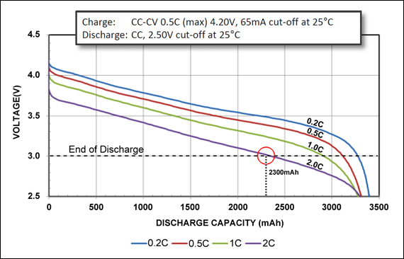 heady plover
Oh I don't need very big ones. The ones I was looking at were 60mm. These are a great price. Thanks 👍
native cipher
in general, GoBilda is a great source of parts for midsize robots. They sell mechanical parts, motors, servos, axles, hubs... you name it
primal shell
It's useful for other things than robots, but I agree, it's really nice for robots.
 pine bramble
primal shell
It's useful for other things than robots, but I agree, it's really nice for robo...
pine bramble
primal shell
It's useful for other things than robots, but I agree, it's really nice for robo...
The thing that stung me was that GoBilda is metric, ServoCity Imperial units. I wish I'd known about the former before I'd put in an order for ~$400 of Imperial unit parts for what will be a metric robot.
dry smelt
What is a good way to attach things to a stepper motor (Like a wheel, or platform, or box etc?) like this https://www.adafruit.com/product/324
Since I've got a 3d printer my simple idea was to print a hole/slot for the shaft. But how would I 'bind' it, so that it does not easily remove. I would prefer not to use super glue :p

A stepper motor to satisfy all your robotics needs! This 4-wire bipolar stepper has 1.8° per step for smooth motion and a nice holding torque. The motor was specified to have a max ...
lone skiff
Often motor shafts are made in a D shape, so they have a flat surface that a set screw inside a coupler can fasten down onto.
native cipher
dry smelt
What is a good way to attach things to a stepper motor (Like a wheel, or platfor...
you can use these hubs by pololu: https://www.pololu.com/product/1998

These universal aluminum mounting hubs allow you to mount custom wheels and mechanisms to 5 mm diameter motor shafts. The set includes two hubs, two M3 set screws for securing the hubs to motor shafts, and one 1.5 mm Allen wrench for use with the set screws. Each hub has four threaded mounting holes for M3 screws (not included).
Set screws have their problems, but it still much better than 3d printing hubs
or these hubs - more expensive, but much more reliable:

goBILDA
manic depot
Hi, my little bot has Motorshield V2 controlled from an ItsyBitsy M4. The M4 waits for serial commands in cycles and than controls the Motorshield. Has anyone a good example for exact DC Motor Control ? Exact as in make sure every DC Cycle time is the same with circuitpython ?
 celest burrow
Can anyone give good suggestionz to getting started with ROS
manic depot
@celest burrow there is a large tutorials section on here https://docs.ros.org/en/foxy/Tutorials.html
celest burrow
Thanks @manic depot
 bitter geyser
If anyone fancies a weekend of robotics action, Pi Wars is being streamed this weekend, 9.45am-4pm UK time (GMT+1). Go to piwars.org and click the BIG RED BUTTON 😄