#help-with-robotics
1 messages · Page 4 of 1
 hollow wedge
 hot sable
Hello good people, how y’all doing, am lost in this field , please i need help 😔💔
 olive light
Don't hesitate to explain your problem and ask questions.
If anybody knows the answers, they will answer.
 inland bear
Where is the project based (location)? I've been keen on the weeding ros2 robot idea for a while, along with liking the farmbot stuff (UTM dettachable toolheads is a good idea).
 hollow summit
Farmbots are fun but don't really scale. I have one here i need to reassemble. Project is largely based near Bristol UK, but volunteers in Lincoln, US and Brasil. Working on some affordable dev platforms to make volunteering easier
inland bear
hollow summit
Farmbots are fun but don't really scale. I have one here i need to reassemble. P...
100% agree, farmbots were an interesting research project. I'm Bristol based, so possibily able to help!
hollow summit
inland bear
100% agree, farmbots were an interesting research project. I'm Bristol based, so...
I'll drop you a dm..
 bright terrace
play_file("ID-10_Move.wav")
pixels.fill(WHITE)
pixels.show()
for angle in range(0, 120, 1):
servo.angle = angle
time.sleep(0.01)
for angle in range(120, 0, -1):
servo.angle = angle
time.sleep(0.01)
crickit.servo_1.angle = 45```
Hello Robotics Friends - Question for python+circuitplaygroundbluefruit+crickit - I want the audio file to play at the same time as the servo sweeping - what would be the best way to go about this? thanks in advance obtuse monolith
Does circuitplsygroundbluefruit support asyncio?
I suppose the trouble is going to be whether there’s an asynchronous version of play_file
 cursive helm
obtuse monolith
Does circuitplsygroundbluefruit support asyncio?
cursive helm
obtuse monolith
Does circuitplsygroundbluefruit support asyncio?
According to the download page, _asyncio is included so you hould be able to use this board with the asyncio library. You will need to to install it from the library bundle. As to play_file, I don't know if there is any asyncio support available. Hopefully someone else can answer that.
 dense isle
can someone help me understand what my servos are doing? i'm working on a walking quadruped, and it mostly works fine. However... I've also built a servo tester, as I've found (especially for the cheaper servos like MG90S) that the activation range isn't very consistent between servos. I start out setting the zero point (minimum pwm) so that the pointer lines up with the zero mark on my test jig... then i do the same for 180, going back and forth to make sure both hit the line. However, when I set it to 90 degrees, it's almost never pointing at 90... sometimes 5 or 10 degrees off. Is this expected? or a questionable motor? or...?
and... for some values, for example 690/2730, the current motor is off by maybe 3-5 degrees; but at a much lower value, 295/2375, it's almost dead on.
olive light
90° is all that is guaranteed (at roughly 1000 to 2000us duty, with 1500us in the center), because that's the standard for hobby servos, many servos allow more, just because they don't have a mechanical stop, but there is no guarantee
I have also noticed that cheap servos tend to have uneven steps -- so 100us change on one end of the range results in different physical movement than on the other
generally, if you need high precision/repeatability, they you have to use more expensive servos, or switch to smart servos
dense isle
olive light
90° is all that is guaranteed (at roughly 1000 to 2000us duty, with 1500us in th...
i just need consistency between servos, so that the legs match position... i have coded the "calibrated" values so that each joint can be set differently... was just wondering why the 90 is so inconsistent depending on where I set the endpoints. and as this is purely a hobby, the nicer expensive servos are way out of the price range. i'm desigining a hexapod that will use the larger MG996R servos... the couple i have seem more reliable than the tiny MG90s... but even at the aliexpress price of somewhere around $4 per motor, it's gonna be a little while before I can get them.
olive light
I had some luck with FeeTech SCS0009 smart servos -- they are pretty much drop-in replacements for mg90 in terms of size and weight, but they use a serial protocol for communication. You can see my (ongoing) experiment with them at https://deshipu.art/projects/project-190377/
bright terrace
cursive helm
According to the download page, _asyncio is included so you hould be able to use...
thank you jerryn and marshall for pointing me in the direction of asyncio... i'll dig around the adafruit website to see if i can figure it out, thanks!
olive light
dense isle
i just need consistency between servos, so that the legs match position... i hav...
I work around cheap servos by having two "zones" of movement with different steps defined, that gives be enough consistency for reasonable walking
dense isle
olive light
I work around cheap servos by having two "zones" of movement with different step...
so far, walking itself is pretty much OK. i'm using some concepts from the Sesame project, including various poses. A couple of those, where the front legs are out in front parallel to each other, it's obvious that the forelegs don't line up properly. I'm going to redo the calibration/testing for those motors, and see if i can find a consistent spot.
olive light
dense isle
so far, walking itself is pretty much OK. i'm using some concepts from the Sesam...
for the perfect lineup, you would have to profile each servo on all of its range -- this is doable, but probably overkill
dense isle
aye
i'm probably going to keep this one as it is. i'll just treat it kindly, as if it has a slight physical disability. 😉
 strong oasis
Hey guys. I am currently working on a robotics head that has 6 mg90 servos and 4 mg996r servos. These servos are connected to 2 pca 9685 servo controllers. I am powering the servos externally using lever connectors that connect directly into the power supply. I am using a 5v power supply that can go up to 30 amps. For the ground, it is connected both to the esp 32 and to the servo controller boards through the screw terminals. I am sure I have all the mapping right but all of the servos except 2 mg996r servos move. During the time that it is moving, the led light on the pca9685 boards dim and brighten depending on the movement of the servo. In addition, the servos that are move don’t seem to move how it used to move prior to changing the circuit. The program that I am using to create my animation on is called bottango. It would be very much appreciated if someone has an seer to my problem. :)


 dense isle
olive light
I had some luck with FeeTech SCS0009 smart servos -- they are pretty much drop-i...
dense isle
olive light
I had some luck with FeeTech SCS0009 smart servos -- they are pretty much drop-i...
Those do indeed look interesting. One additional newbie question (for now, anyway) - how do you translate the rated torque (say, 2.3kg) into how strong a motor you need for a particular robot? Does any one joint have to support the whole weight? Or do they work together? Say I have a hexapod that will weigh 1 kg... how should I spec each motor?
My first one is based on the open source sesame quadruped, and is small enough that the mg90 was plenty. But I have very little idea how to scale it up.
olive light
For a quadruped, for a statically stable gait you always need to have three legs on the floor, so the weight gets distributed between those, albeit not always equally. If you use a more dynamic gait like trot, then it's two legs. For a hexapod it depends even more on the gait, but usually you want at least three legs on the floor, and the weight tends to be more equally distributed. Depending on the size of your robot and the desired speed of movement, you also have to include some margin for inertia. This could be all calculated exactly, but it's quite complicated without specialised software, so I mostly go with trial and error, and make the legs shorter than the servos would theoretically allow.
obtuse monolith
strong oasis
Hey guys. I am currently working on a robotics head that has 6 mg90 servos and 4...
I’m not sure I want to troubleshoot that spaghetti. Can you isolate the issue?
dense isle
strong oasis
Hey guys. I am currently working on a robotics head that has 6 mg90 servos and 4...
The LED dimming and brightening tells me that you might be having voltage drop - i.e., it's not staying at 5V as much as you think.
As for the servos that aren't moving - try plugging them in to a spot where a working one is currently attached - if they move, then you've got a problem with those other pins on the board. Not likely, as they're all driven by the same IC, but it's a starting point. Otherwise, you might just have bad servos. Most of the hobby-grade servos have a pretty high failure rate - I think I have 4 bad ones out of 25 or something like that.
strong oasis
dense isle
The LED dimming and brightening tells me that you might be having voltage drop -...
Basically through testing, when i first start the animation and run the program, most if not all servos are running. After 2-3 trials however, all of the servos shut off and not moving except for 2 mg998r servos.
For the LED dimming and brightening, what do you reccomend to fixing the voltage drop?
strong oasis
obtuse monolith
I’m not sure I want to troubleshoot that spaghetti. Can you isolate the issue?
My main issue right how is being able to distribute the power more efficiently and safely. Prior to powering the servos separately from the 5v, I had power running directly into the screw terminals. However, a sudden surge when initiating all of the servos caused this chip to explode. Is it safer to chain the 5v directly into the servos, or do you have any other recommendations to limit the possibilities to the failure?
 obtuse monolith
Is that a regulator?
You’ll notice the Adafruit design has a DPAK there instead of the little SOT-23
So their solution was to choose a bigger component
 dense isle
strong oasis
Basically through testing, when i first start the animation and run the program,...
dense isle
strong oasis
Basically through testing, when i first start the animation and run the program,...
ah, i mis-understood what was failing. I'll have to give that one some thought.
as for the voltage... i know that in smaller configurations (like the Sesame project's quad), which are powered by a lipo battery pack, they limit how many servos are running at once to avoid the "brownout", since the processor is also powered by the same battery and will not run properly on low power. The LED in question is powered by the incoming voltage from the processor, so is a good indication that you might experience weird code issues due to the voltage. I think the first thing I'd try is to run the processor off of a different supply - a USB wall charger will probably do the job. This will ensure that the MCU isn't starved for power.
I just looked up the board schematic. The chip that blew up was a reverse voltage protection mosfet. If you're sure you had it the power hooked up right, it might have just had too many amps going through it. (Of course, if you hooked it up backwards it would have failed differently). Another possibility is (from the Adafruit learn page for their version of the board): "V+ - This is an optional power pin that will supply distributed power to the servos. If you are not using for servos you can leave disconnected. It is not used at all by the chip. You can also inject power from the 2-pin terminal block at the top of the board. You should provide 5-6VDC if you are using servos. If you have to, you can go higher to 12VDC, but if you mess up and connect VCC to V+ you could damage your board!"
If your power supply is reliable, and is actually capable of 30A, I would think you'd be OK to run the servos off of it. HOWEVER: from your description of the issue, it sounds like something is getting too hot and shutting off for a while. When it happens, check your wiring and see if there are any wires that are hot to the touch. SG90s have a stall current of around 650ma... which would put 6 of them at almost 4.5A. The larger wires I see in the pictures should be able to carry that much, but it's worth checking.
strong oasis
dense isle
ah, i mis-understood what was failing. I'll have to give that one some thought....
So I have narrowed it down to just using an mg996r servo to test. The program runs in its entirely and works perfectly when I use a 2 amp power supply. I am also using a UBEC power regulator to bring the volt from 12 down to 5 volts which goes into a distribution block. I will eventually have to add 10+ servos which means the 2 amp power supply won’t be enough. When I hook it up to my nice-power power supply that is capable up to 30 amps, it runs for a couple seconds then stops. I even tried adding a light bulb to provide constant amps in case the servo spike was causing a problem with the power supply and it still did not work properly. Are there any solutions you have or better power supply options?


 olive light
strong oasis
So I have narrowed it down to just using an mg996r servo to test. The program ru...
olive light
strong oasis
So I have narrowed it down to just using an mg996r servo to test. The program ru...
does it work correctly when you power the microcontroller board from usb, and the servos separately from your power supply?
when you have it connected over usb, is there an error on the repl console when it stops?
strong oasis
olive light
does it work correctly when you power the microcontroller board from usb, and th...
The esp32 is powered through usb separately from servos
olive light
strong oasis
The esp32 is powered through usb separately from servos
and any errors?
strong oasis
olive light
and any errors?
The error described above is what happens when I power the esp32 through usb
olive light
strong oasis
The error described above is what happens when I power the esp32 through usb
I didn't see you quoting any errors
my "errors" I mean "error messages"
strong oasis
The error is a hardware wiring issue where when I am powering it using a 12v 2 amp power supply through a servo UEBC it runs perfectly. But when I switch it to a high grade power supply that can go up to 30 amps. The servos run inconsistently and stops only after a few seconds of running even though it should run at least 45 seconds.
olive light
strong oasis
The error is a hardware wiring issue where when I am powering it using a 12v 2 a...
can you confirm you are not getting any messages on the repl console?
 mortal heron
Hey guys, I hope you're all doing well. I need some help with the power supply for my project. About two days ago, I went to a university event where I was supposed to present my project and demonstrate its functionality. The problem lies in the number of servos and the power supplies. I'm currently using a 12V, 5-amp power supply, and after about 10 minutes, the converters I'm using get extremely hot and melt the plastic casing. I'm using LM2596 adjustable 12V to 6V converter modules. The robot currently has about 12 servomotors running simultaneously, connected to an Arduino Mega for control and a PCA9685 for the servo PWM. I need a recommendation for power supplies for the robot and 6V converters, preferably adjustable, as I plan to use high-voltage servos later. Thank you very much and sorry for taking up so much time. (i have a 8 sg90 and 4 mg995 conectd on a pca9685)


 obtuse monolith
Ok. Let’s figure out your power budget.
What is the stall current for all your motors?
Iirc the sg90 are 700mA and the mg995 are 2.5A, so that comes to 15.6A. This is the peak current that your converter may be asked to supply. The typical load depends on your application, but I would estimate 1/4 of that or 4A.
If all you have is a pile of LM2596, you could split up the motors. They’re only rated at 3A so that means a one can supply power for a single mg995 or up to four sg90. This may actually be an economical way to go, as they come in 10 packs on Amazon. To ensure sufficient power you will need a DC supply rated for 120W, but you can try with your existing supply (60W?) and see how it fares
mortal heron
obtuse monolith
If all you have is a pile of LM2596, you could split up the motors. They’re only...
Thank you so much for the information. Is there a specific power supply you could recommend? And what more efficient alternatives are there to the LM2596? The robot operates using pre-recorded keyframes, and the 12 motors I mentioned are always running, so I need the most reliable alternative possible. I've already spent a lot of money on different power supplies, and none of them have worked.
obtuse monolith
mortal heron
Thank you so much for the information. Is there a specific power supply you coul...
You already have multiple power supplies and no single one has worked. Why not use more than one?
A single 6V 100W power supply is going to be expensive, but your motors don’t all need to be on the same power supply. They just need the same return voltage (GND).
 half socket
Hey guys! posted this issue in the Adafruit reddit page but I figured I would have better luck on the discord!
Basically I am having noise/sound issues with my build, all the specifics are in the post: https://www.reddit.com/r/adafruit/comments/1senbhp/pca9685_annoying_jitter_sound/
Oh and I got a sound recording too
Any help or insight is appreciated!
obtuse monolith
Can you isolate the issue? What happens if you unplug a few of the motors?
I’m assuming the motors all respond correctly?
half socket
ill try when I get home
but yes all motors respond correctly, they just do the noise, I talked to others about it and it seems to be a somewhat common issue
there is one single quirk I am having with the boards and it is that on 2 slots, my servos turn on even if they SHOULDNT, external power is NOT plugged in, but this seems like a weird behavior caused by my wiring
(btw this happens when i try to program the nano, you can see my wiring diagram for the idea)
But yeah, any ideas/leads you can think of with the little information I have for you right now or is it still a mystery?
oh and when external power is cut, there is still 2.5v running on the power lines
obtuse monolith
My guess is the servos are injecting noise onto the 5V line. You might be able to fix this with capacitors or chokes.
half socket
I have 1000uf caps on the boards themselves if that is what you meant and wdym by chokes?
obtuse monolith
Don’t heart this yet! You might not like my solution
half socket
Alr, im ready to hear it 😂
obtuse monolith
This is a snap-on choke
Probably you'll want something with a lower test impedance
The problem is they're heavy
Another option is a tantalum capacitor. I am sure the 1000uF electrolytic capacitors do not have good high-frequency response
Anyway, conducted emissions is not a fun problem, so I hope someone suggests something else
half socket
obtuse monolith
This is a snap-on choke
oh right I remember now
half socket
obtuse monolith
The problem is they're *heavy*
not that much right? wait let me look...
obtuse monolith
I just picked one for reference. No idea if it's a good choice
Ah. Digikey calls them "cable ferrites"
half socket
yes but I would guess that if I do end up using them, it would be around 10-30 grams each no?
also, for the tantalum caps, if I just solder them on the backside pins of the 1000uf cap, that would be a good place to put it correct?
obtuse monolith
Here's a lower frequency option https://www.digikey.com/en/products/detail/fair-rite-products-corp/0475178281/8594142
half socket
and I also saw people suggesting using the OE pin, would it be worth giving it a shot or not really in my case
obtuse monolith
The issue could also be from your 5V buck converters
Anyway. Do you have access to an oscilloscope to measure?
half socket
yes, I even have a lab tommorow so I will have access
obtuse monolith
We're looking for AC noise riding on the 5V line. Could be anywhere from 60Hz to 10MHz, but it will be helpful to know the frequency and amplitude (or better yet, post a picture of the oscillogram)
half socket
ok I will test for it, thanks man I have a list of things to try now, ill et back to you by tommorow
 slender sluice
Im new to robotics and have a question regarding motor controllers.
If my robot has subsystems that each have multiple identical motors that are always required to rotate at the same speed and position is irrellevant, can I only use 1 motor controller per subsystem? Does this make each set of motors act as a single node in the CAN bus? Our team lead is insistent on using CAN and BLDC motors and the motor controllers are pretty pricey for our broke college student asses. So any help with this would be really appreciated
obtuse monolith
slender sluice
Im new to robotics and have a question regarding motor controllers.
If my robot...
Depends on the type of motor and how closely you can guarantee identical speeds/torques. It’s worth trying.
CAN in general is expensive, because It’s licensed from Bosch.
But now I’m wondering what kind of system you could have where open-loop motors are expected to move synchronously without mechanical linkage
slender sluice
In short, its a system that hangs off a cable and then uses propellers to generate thrust to rotate it to avoid the poles the cables are being suspended by
I was hoping to use 1 motor controller for the propellers and 1 for the propulsion motors
and an IMU to implement some kind of closed control to increase and decrease the propeller speed
still in very early design/concept generation so thrust/torque requirements are still pretty unknown
slender sluice
obtuse monolith
But now I’m wondering what kind of system you could have where open-loop motors ...
but when you mention mechanical linkage, that would make a lot more sense for what we're doing
obtuse monolith
slender sluice
but when you mention mechanical linkage, that would make a lot more sense for wh...
For the drive, definitely. For the propellers, it may be harder
Why is your team lead insisting on CAN?
Did they make a pugh matrix to evaluate the options?
slender sluice
obtuse monolith
Why is your team lead insisting on CAN?
hes got a lot of experience in FRC competition and its what he's used to is my understanding. Not sure what the benefits are over other protocols
slender sluice
obtuse monolith
Did they make a pugh matrix to evaluate the options?
not too sure, I joined the team a bit later. But I'll bring it up
obtuse monolith
slender sluice
hes got a lot of experience in FRC competition and its what he's used to is my u...
I was worried you would say that. The FRC CAN implementation sucks, unless they fixed it since 2012
Instead of using the heartbeat for global watchdog, they sent a watchdog packet to each node, severely limiting throughput
slender sluice
Not sure if theyve changed that, but surely after 14 years they wouldve done something
obtuse monolith
lol
slender sluice
our team lead was originally planning on using only FRC parts like the roboRIO for this project, but the cost was going to be 5 times over what the Uni gives us, so I suggested to try and use an esp32 based system
not sure how much Ive stuffed us in terms of workload
obtuse monolith
Esp32 is fine so long as you don’t need a good ADC. Rp2040 is good too
slender sluice
obtuse monolith
Esp32 is fine so long as you don’t need a good ADC. Rp2040 is good too
The project involves an optical camera, thermal camera and other sensors to help with autonomous wireless navigation and inspection. Do you think an esp32-s3 would be enough, or would it need a Raspberry Pi 5 as a companion to handle some of the work?
obtuse monolith
You’ve got to define your requirements first. What kind of processing are you doing? How quickly does it need to respond? What are your physical constraints (weight, power, size)?
The Turtlebot3 has a STM32H7 and a Raspberry Pi 4 but offloads SLAM to an external laptop over WiFi. Maybe if it had a Pi 5 it could do the processing on-board
But that’s only with a low-speed LIDAR sensor. Are you expecting to process live video for navigation with an ESP32-S3? It might be possible if you move slowly. Tell me more about the algorithms you had in mind
Are you doing classical techniques or CNN?
slender sluice
I think at this point, our requirement is only for the system to navigate along the cable and to send the camera feeds to a pc to do processing
it's meant to travel along the cable to detect for damage/faults, so it wouldn't travel fast
obtuse monolith
Ok. ESP32 is fine. The S2 and S3 are nice if you’re doing circuitpython
slender sluice
obtuse monolith
Are you doing classical techniques or CNN?
at this moment, Im not too sure what I'd use. I'd want to implement a CNN, but it's not a requirement at the moment
obtuse monolith
slender sluice
at this moment, Im not too sure what I'd use. I'd want to implement a CNN, but i...
You’re detecting damage to the cable using vision? Wouldn’t the robot be at risk if the cable were damaged?
slender sluice
realistically, yes. But our project is just meant to be a proof of concept of a maintenance kind of robot, detecting issues before they become that bad
so you can send a robot along kilometers of line rather than have someone drive and inspect it or follow strict drone laws
obtuse monolith
For power transmission lines? Interesting
obtuse monolith
Obviously you’ll need more than a 10ft fiberglass pole that linemen use if you’re placing the robot on a 200kV wire
slender sluice
we're targeting lower voltage distribution lines (~13kV)
obtuse monolith
Ah, that’s easier then
Did you find a way to navigate past the glass insulators?
slender sluice
we've been talking with some experts about what kind of clearance we'd need to be safe from flashover and stuff and they said maybe ~0.9m
obtuse monolith
I am very interested to see how this turns out
slender sluice
obtuse monolith
Did you find a way to navigate past the glass insulators?
our current running idea is a robot that hangs from the cable at 3 seperate points with telescopic arms, then can detach each arm when it gets to the insulator then reattach it once it clears the insulator
obtuse monolith
So you have RC servos or something to control the telescoping arms?
slender sluice
not too sure on detailed design yet
slender sluice
and its possible to control multiple motors with the same motor controller?
obtuse monolith
You have a lot of complexity here, so I imagine that ease of implementation is a major concern
obtuse monolith
slender sluice
and its possible to control multiple motors with the same motor controller?
yes in parallel but torque might not be equal
slender sluice
since Im new to robotics and motor control etc, could you point me to any resources to learn more?
obtuse monolith
Oh. Hmm. I’m not sure I learned this online. Can you be more specific?
slender sluice
ah its alright, I'll just search stuff up when I hit a roadblock
thanks Marshal, youre the goat
obtuse monolith
Thanks. I really am curious to see what you make
half socket
@obtuse monolith

lil clearer

So I am guessing there IS noise and I should add some type of cap? tantalum like you said?
(there measurements are for v+ to ground on the PCA driver
obtuse monolith
@half socket Yes, definitely some noise there. Still hard to say much about it. Set the decoupling to AC, zoom in on the voltage and frequence scales. Use the trigger to capture the falling edge of those dips and the cursors to measure it.
olive light
large caps are bad at filtering high-frequency noise, that's why you often use a pair of a smaller (100nF) and larger (10uF) capacitors
obtuse monolith
Depends on the type of cap too. Electrolytics are particularly bad at high frequency, with MLCC and Tantalum performing better. Lead length also becomes a significant issue above 10MHz due to parasitic inductance
So I'm guessing a 10uF tanatalum will do the trick, but it's no more than a guess because I can't clearly see the amplitude or frequency. If the spikes are less than 50mV, I think we need to look somewhere else
olive light
if you have 10MHz noise on your power line, you have more serious problems than caps
obtuse monolith
Sorry. Yes. I work with RF generators at work too, so 13MHz noise is a common concern
But not here
olive light
I thought that inline inductance is actually good for removing noise? like a choke?
obtuse monolith
olive light
I thought that inline inductance is actually good for removing noise? like a cho...
Yes, but not on the capacitor leads. Thank you for clarifying
olive light
sorry, analog electronics is complete mystery to me
as long as it's 0s and 1s, I manage somehow
obtuse monolith
And if the inductance is between your load and capacitance, it's just as bad. Unfortunately it's very inconvenient to put capacitors right at the load for RC servos.
If the servos are interacting, we should see the problem decrease as you start to unplug them. But if the noise is ripple from the buck regulator, that wouldn't help since ripple increases in discontinuous switching mode.
olive light
some more expensive servos have a cap inside
half socket
obtuse monolith
<@751456029815996436> Yes, definitely some noise there. Still hard to say much a...
oh god, ill try my best lol
still a sem 1 student xD
half socket

this is the best I could get
@obtuse monolith this good or should I ask a teachers help?


I think i managed and I hope this is enough, ill go to class for now and I can take some more if its still wrong
obtuse monolith
Thanks! We can see the big dip there is 500mV high and about 2ms wide. If we suppose that's the result of a pulsed 1A load, then it says the effective capacitance of the system for low-frequency pulses is 500uF. It would take 10x that to fix this - instead we should look at the performance of the voltage regulator.
- Can it support the current that the servos are pulling, or is it maxed out?
- Does it respond quickly to step loads? Good switching regulators should respond in one cycle, which is 1 to 10us (depending on switching frequency)
- Is there significant voltage drop between the regulator and the load? Maybe the wires are too small or too long, or some connectors aren't making good contact
half socket
- according to what people making hexapods tend to measure, a whole haxapod draws about 10A, and I have 7A UBEC's on each side so theoretically it should be able to support it
- wdym?
- when you say between regulator and load, you mean between the UBEC and PCA board rails right? if so, last time I checked it was no that significant, I think around 100mv or less? I would have to measure again, the wires are 10cm of 22AWG tinne copper wires
obtuse monolith
Another thing to notice is the power supply ripple is rather large - it looks like 80mv peak to peak at maybe 20kHz. It's hard to tell exactly. If your regulator is switching at 20kHz you should really pick something else - 100kHz or higher.
 obtuse monolith
100mV on each wire with what load?
half socket
but from what I am getting from this is that I either trouble shoot untill I find a flaw or add stupid amount of capacitance
So in a case where I am short on time, I think the best I would do other than ignoring the noise is changing the 1000uf cap to a 4700 one right?
obtuse monolith
Sure, you could try it
half socket
obtuse monolith
100mV on each wire with what load?
each wire? load?
obtuse monolith
What if you move the SSR to the input side of the UBECs?
half socket
Hmm, good Idea but everything is already soldered and it would do more harm than good trying that
Sadly
obtuse monolith
Soldered?? I thought they were screw terminals
half socket
The relay itself is not soldered but the UBECs are already soldered to a deans connector
obtuse monolith
Oh, I see. How about removing the SSR then, just for testing?
half socket
Oh, good point I can just do that lol
obtuse monolith
The goal is to have a low impedance path between the regulators and the servos
half socket
man im so focused on this project im loosing track of stuff, dont even remember why I put the relay
half socket
obtuse monolith
The goal is to have a *low impedance* path between the regulators and the servos
ahhh makes sense
well if that completly fixes it Ill have to consider resoldering then, and if not, the noise isn't that bad and doesnt hinder performance, plus it should be a tiny bit better with bigger caps
obtuse monolith
I can't find any detailed info on those UBECs, so you'll have to evaluate the performance yourself. https://www.google.com/search?q=step+load+transient+response

www.google.com
half socket
obtuse monolith
The goal is to have a *low impedance* path between the regulators and the servos
honestly amazing sentence, that makes a lot of sense
half socket
obtuse monolith
I can't find any detailed info on those UBECs, so you'll have to evaluate the pe...
alr thanks ill have a look at that, thx again for all your help! I think im good with the info I got for now and whatever outcome will be what it will be, need to start coding as I have a month
Again, tysm for the help, appriciate it a bunch!
obtuse monolith
I hope it works out
Can I ask - why six legs? Is it because they don't fall over?
half socket
Partly because of that yes, but also because I simply wanted to make a hexapod
Its like, why a quadruped vs bipedal robot?
its just different projects and 6 legs looks cool and has no issues for balance 🤷♂️
There really isn’t a good reason, its just fun lol
(cant ignore the fact that complexity increases as you remove legs, which in my case this is my first ever “electronics project” so I have my limits 😅)
 hidden badger
Anyone have advice for how to manage the cables at the base of a robot arm? I’ve tried looping them around the base joint but they keep getting caught and restricting the movement of the arm when I go from +joint limit to -joint limit
 obtuse monolith
hidden badger
Anyone have advice for how to manage the cables at the base of a robot arm? I’ve...
obtuse monolith
hidden badger
Anyone have advice for how to manage the cables at the base of a robot arm? I’ve...
I think it’s case-by case. Can you take video so we can see the kind of motion you’re doing?
hidden badger
hidden badger
obtuse monolith
I think it’s case-by case. Can you take video so we can see the kind of motion y...
is this good
obtuse monolith
Yeah, I see it, so it’s run on the inside of the joint and you want to to wrap both ways. Tricky
Have you considered a slip ring?
hidden badger
One of the wires with the big JST goes to the motor
Not sure how that would work
It worked just fine when it was just this guy:

When I added the two other wires now they all bunch up in the channel and kill it
 snow shale

 mellow carbon
I’ve already started designing a project around Crikit.
 hasty ermine
 clear mantle

 haughty tartan
I'm working on CRICKIT-izing one of my Arduino-powered bots while trying to learn CP from scratch.
 wheat rivet
those are pure amazingness. MST3K was one of my favs growing up.
 cosmic idol
I have a meARM (https://shop.mime.co.uk/collections/frontpage/products/mearm-pi-mime-blue) that I recovered from a returned product bin at hq many years back. It has exactly FOUR mini-servos! Going to introduce the to it next weekend. excited to see how people will handle complex movements in CP
haughty tartan
Thanks @wheat rivet, I'm hoping this crickit can let me give them some more interactive functionality.
 weak kelp
here is some robotics https://www.mistyrobotics.com/

Misty is purpose-built for programmers who've never worked with robots before. As long as you have an imagination, the possibilities are endless.
 rain surge
Is this truly the first instance of a Robotics channel?!?! I feel like I just popped in from an alternate universe.
 thorn dirge
@haughty tartan wow. those are awesome! makes me wanna go watch some mst3k.
 main jolt

Klaatu barada noe Adafruit Circuit Playground Express
Circuit Playground Express and a micro servo. https://youtu.be/wlXcvSo49G4

Animatronic with Adafruit Circuit Playground Express Circuit Python coding Neopixels and servo control
haughty tartan
Tom Servo's conversion from Arduino Uno to CP+Crickit is almost complete.
weak kelp
that misty robotic what it need is  backpack
 sly sand
From what I can observe, the CPX draws power first from the CPX's USB port, and fails over to the Crickit's connected 5V supply (when the Cricket has nothing connected to it except the CPX -- via six conductive standoffs -- and a 5V supply).
The Crickit in this context behaves like a battery backup to the CPX's USB port, to maintain power to the CPX board.
(I used a LiPo battery pack with a USB A jack to provide the 5VDC to the Crickit).
http://adafru.it/1959 http://adafru.it/2697
As long as one of the two power sources remains, the other can be hot-disconnected, at least when there's no client peripherals connected to Crickit.
Program on CPX runs uninterrupted, in this context.
Once a load is connected to Cricket (servo &c.) the Guide's recommended powering strategies are applicable.
My observations mainly apply to a circumstance when it is desired to program CPX without disconnection from Crickit, and nothing else is connected to either (other than the USB programming cable, and/or the +5V to the 2.1 mm DC barrel jack on Cricket).
sly sand
Connecting the Charger Doctor to the CPX USB port, while CPX was powered (via Crickit +5V 2.1 barrel jack) and running a program (using the array x10 NPX to show colored light) .. Charger Doctor didn't even power on.
That's a good thing. ;)
Summary: I couldn't find anything that worries me. ;)
cosmic idol
oh yay, i'm sharing a table at ELI Makerfaire is next to this robot (https://twitter.com/Volt_the_Robot/status/999756507112714241). It gives out hugs 😄
mellow carbon
I took a few moments this morning to figure out my crikit mounting. Looog bolt though the crickit, though the supplied spacer, through a layer of cardboard, and into another 10mm spacer that the CPX mounts to. So crikit is behind the case, CPX is in front (so the neopixels are visible). Next is to get some washers or spade things to tap into I2C nicely.
main jolt
@mellow carbon CRICKIT BISKIT?
sly sand
That's a good idea @mellow carbon
I don't like long bolts so I usually cut off a screw's head and dress the end with a file, and test it to make sure it's smooth - creating a double-male joiner (threaded rod stock, but in a machine screw thread) to join F-to-F threaded standoffs.
 idle valve
@main jolt A Criscuit?
main jolt
@idle valve You may need Cronuts to fasten the bolts.
 surreal elbow
@idle valve Is that what an American born Brit calls a cookie?
idle valve
I honestly could have swore "Criscuit" was a brand of something, but I guess I was thinking of Triscuit
main jolt
Crisco routers? Multiple operating systems baked in.
haughty tartan
When I try to upload Arduino code to the CPE+Crickit it switches the USB port and drive mount to CPLYBOOT and I get a "programmer did not respond to command" error from the Arduino IDE. Is there something special I need to do before programming the crickit with Arduino vs CP?
I wonder if I need to burn the bootloader?
thorn dirge
@haughty tartan does the CPE show up in the ports list in the Arduino IDE?
haughty tartan
Yes
thorn dirge
what are you selecting for Board?
haughty tartan
Adafruit Circuit Playground since that's what the crickit instructions suggest.
thorn dirge
I think that's for the classic, there are two version of Circuit Playground
let me see exactly what they are called....
do you see these two different options? "Adafruit Circuit Playground Classic" and "Adafruit Circuit Playground Express"
haughty tartan
The other one is Adafruit Circuit Playground Express, I tried that too and if flashed the board.
I'll try that again
thorn dirge
and just try loading the blink example for a simple test
can you link to the instructions you were reading?
haughty tartan
Actually, it doesn't even say that anymore. https://learn.adafruit.com/adafruit-crickit-creative-robotic-interactive-construction-kit/arduino-code

Make your robot pal who's fun to be with using Crickit!
I get a laundry list of errors when trying to use the CPE as the board with the blink example, starting with In file included from sketch\BlinkTest.ino.cpp:1:0:
C:\Users\Packr\Documents\ArduinoData\packages\arduino\hardware\samd\1.6.18\cores\arduino/Arduino.h:124:0: warning: "digitalPinToInterrupt" redefined [enabled by default]
#define digitalPinToInterrupt(P) ( P )
thorn dirge
hmmm. something's up with your Arduino setup.
you're loading File -> Examples -> 01. Basics -> Blink ?
haughty tartan
I copied Blink from here: https://github.com/adafruit/Adafruit_Seesaw/blob/master/examples/digital/blink/blink.ino
 thorn dirge
and Tools -> Board says "Adafruit Circuit Playground Express" ?
haughty tartan
Yep
thorn dirge
hmmm. just did a test build here and it worked.
haughty tartan
Maybe it is my IDE setup then.
thorn dirge
i think so. trying to think what to check next...
try compiling the other blink example, the one without seesaw, so just File -> Examples -> 01. Basics -> Blink
and you can test compile by just clicking the check mark button in Arduino
haughty tartan
Same thing, it's definitely the IDE. I'll wipe it out and start from scratch.
thorn dirge
ok...if you're going to do that, there's a folder you should also delete for a clean install
hang on...
C:\Users\(username)\AppData\Local\Arduino15 so for you, that looks like it would be:
C:\Users\Packr\AppData\Local\Arduino15
haughty tartan
Cool, thanks for the help!
thorn dirge
and then here are the instructions for setting Arduino for CPX:
https://learn.adafruit.com/adafruit-circuit-playground-express/set-up-arduino-ide
haughty tartan
Should I do that first before following the Crickit instructions?
thorn dirge
and just as an FYI, here's some info on CPC (older classic) and CPX (newer):
https://learn.adafruit.com/adafruit-circuit-playground-express/classic-vs-express
yep. get your Arduino setup working first before moving on the the crickit stuff.
the blink example (File -> Examples -> 01. Basics -> Blink) is a good simple test
haughty tartan
Hmm, maybe you should update the Crickit instructions to say that.
thorn dirge
can pass that on. that guide is probably in work, given how new crickit is.
haughty tartan
True. 😄 Thanks again!
thorn dirge
i've gotta run. but will check back later to see if you got things working. good luck!
haughty tartan
So, I think it's something to do with the seesaw library. When I install v1.01 from the IDE the library doesn't have the crickit libraries like the seesaw library on Github does. So my compile fails. But if I install the library from Github, that's when I get all those errors I described above. Everything else works fine up to then, even the CPE, all until I try to do anything with the Crickit.
It even fails with a verify compile before I even try to upload to the Crickit now.
sly sand
Wait a minute. The Crickit is SAMD21 and is, iirc, a Trinket M0 in disguise.
haughty tartan
I installed the SAMD boards and have it set to Circuit Playground Express.
sly sand
No. Crickit is not CPX. Unbolt the two to make this crystal clear. at least, mentally unbolt them. They're unrelated target boards. ;)
I can't find the reference but very recently I read you had to select 'Trinket M0` to compile in Arduino IDE for some other, newly released, Adafruit board. It almost has to be Crickit.
I updated my Crickit firmware the other day and it behaves like a CircuitPython board does -- in terms of reset switch operation and the drive(s) presented in your local fileystem (for drag and drop .UF2 updates).
*https://github.com/adafruit/seesaw/ is the source tree for Cricket if I'm not terribly mistaken.
haughty tartan
Yep, that's the library in installed from zip after the 1.0.1 didn't work. So, change the board in board manager then?
sly sand
Try the README.md (I just noticed this 30 seconds ago)
To make a SAMD09 breakout:
make BOARD=samd09breakout
So crickit is going to have a make BOARD= target, too
unless I'm just plain old wrong (quite possible).
haughty tartan
I'll be back, have to grab dog from groomers.
sly sand
take care!
lib/qp/extras/fw_log.cpp
arm-none-eabi-g++ -mthumb -mcpu=cortex-m0plus -Os -g3 -DSAMD21 -D__SAMD21G18A__ -DBOARD_CRICKIT  -ffunction-sections -fdata-sections -fno-rtti -fno-exceptions -c -std=c++11 -MD -MP -MF "build/crickit/lib/qp/extras/fw_log.d" -MT"build/crickit/lib/qp/extras/fw_log.d" -MT"build/crickit/lib/qp/extras/fw_log.o" -Wall -Werror  -I. -I./include -I./bsp -I./lib/qp/extras -I./lib/qp/include -I./lib/qp/source -Ilib/qp/ports/arm-cm/qxk/gnu -I./boards/crickit -Ilib/cmsis/CMSIS/Include -Ibuild/crickit -Ilib/samd21/samd21a/include/ lib/qp/extras/fw_log.cpp -o build/crickit/lib/qp/extras/fw_log.o
In file included from lib/qp/extras/fw_log.cpp:36:0:
./include/SeesawConfig.h:7:10: fatal error: build_date.h: No such file or directory
 #include "build_date.h"
          ^~~~~~~~~~~~~~
compilation terminated.
Makefile:148: recipe for target 'build/crickit/lib/qp/extras/fw_log.o' failed
make: *** [build/crickit/lib/qp/extras/fw_log.o] Error 1
 $
 $ ag build_date.h
scripts/datecode.py
6:f = open(sys.argv[1] + '\\build_date.h', 'w')
8:f.write("#ifndef BUILD_DATE_H\n#define BUILD_DATE_H\n")

include/SeesawConfig.h
7:#include "build_date.h"
I'm guessing I need to reread the prerequisites for building, with emphasis on satisfying use of Python for this.
Looks like there's a bug somewhere. Found build_date.h with extra chars in the filename.
 $ ls -la | egrep build_date
-rw-r--r--  1 nis   nis    107 May 27 21:25 .\build_date.h
 $
I'm guessing I need to wait a bit longer for Arduino then? 😄
especially to include Adafuit_Crickit and seesaw_servo in what I'm doing.
sly sand
Nah I'm about to kludge this -- looks like that python script did its job but failed to name the output file correctly. I'm going to try just adding that file to satisfy the compiler, by making a copy of the badly-named file to the correct name.
Since I've already rewritten the crickit firmware flashROM once, successfully, I don't see any risk in trying to update it meaningfully (with local mods by me).
looks like it built correctly. put the build_date.h in the base directory. It's there with the wrong name already.
arm-none-eabi-objcopy -O binary build/crickit/seesaw-crickit.elf build/crickit/seesaw-crickit.bin

   text    data     bss     dec     hex filename
  17632     252   20580   38464    9640 build/crickit/seesaw-crickit.elf
 $ cd build/crickit/
 $ ls -la see* ; /bin/pwd
-rwxr-xr-x 1 nis   nis     17884 May 27 21:35 seesaw-crickit.bin
-rwxr-xr-x 1 nis   nis   1314252 May 27 21:35 seesaw-crickit.elf
-rw-r--r-- 1 nis   nis    699077 May 27 21:35 seesaw-crickit.map
../seesaw/build/crickit
 $
1.3 megs sounds a tad excessive so I'm guessing the .bin is the correct file to send to the target. ;)
I have to generate a bossac command line now, to try an upload.
$ ../.arduino15/packages/arduino/tools/bossac/1.7.0/bossac -i -d --port=ttyACM0 -U true -i -e -w -v ./seesaw-crickit.bin -R
 turbid trail
@haughty tartan You should not need or try to upload anything via the USB port on the Crickit. Is that what you're trying to do? If you attach your CPX to the Crickit with the standoffs, then you'll load programs onto the CPX, and it will control the Crickit via I2C.
haughty tartan
The problem isn't uploading, I was trying to upload through the CPE, but I can't even compile because Adafruit_Crickit and seesaw_servo aren't in the seesaw library and when I try to pull them from the latest on Github I get a slew of errors during compile.
turbid trail
Is this the library you're using? https://github.com/adafruit/Adafruit_Seesaw
That's the seesaw client library, not the code that's running on the crickit board.
haughty tartan
That's one of the ones that I tried.
turbid trail
so you added that as a library to Arduino? note that since the last release (1.1.0) there have been some fixes and additions. If you added from Github you'll get those changes
haughty tartan
I'm trying to program the CPE+CRICKIT with Arduino. I tried using the instructions for just the Crickit and that failed. I tried adding the CPX as a board then tried that and it failed. I tried with the 1.0.1 seesaw lib and that failed, and I tried with the github and that failed.
turbid trail
ok, i see - crickit support wasn't added until 1.1.0, and so if you fetch the version through the Arduino Library Manager it will be too old. Then you cloned (or unzipped the library) from github instead, in the same place (like Arduino/libraries)?, and then which code were you trying to compile?
i'll try to reproduce your problem
haughty tartan
Yes, I added the lib from zip that I got from Github. My code includes Adafruit_Crickit.h and seesaw_servo.h but when I try to do a verify compile it gives me a long line of errors starting with:
In file included from sketch\CRICKIT_Tom1.cpp:1:0:
warning: "digitalPinToInterrupt" redefined [enabled by default]
#define digitalPinToInterrupt (P) ( P )
turbid trail
can you drop your sketch here? Use the "+" on the left to upload the file.
 sly oasis
When will crickit’s be available?
haughty tartan
turbid trail
@sly oasis the first run ran out, but more are on the way. we don't do eta's because guaranteed times are hard, but rest assured we're working on it.
turbid trail
@haughty tartan I tried your file and it compiles 😕 . What is the name of the dir in your Arduino/libraries directory and what is in that dir?
haughty tartan
when I downloaded from github I extracted and renamed the dir to Adafruit_Seesaw_Library then added the library from zip via the IDE.
turbid trail
halbert@salmonx:~/Arduino/libraries/Adafruit_Seesaw$ ls -l
total 200
-rw-r--r-- 1 halbert halbert   1657 May 27 18:01 Adafruit_Crickit.cpp
-rw-r--r-- 1 halbert halbert   1328 May 27 18:01 Adafruit_Crickit.h
-rw-r--r-- 1 halbert halbert  29383 May 27 18:01 Adafruit_seesaw.cpp
-rw-r--r-- 1 halbert halbert   7539 May 27 18:01 Adafruit_seesaw.h
-rw-r--r-- 1 halbert halbert 108388 May 27 18:01 Doxyfile
drwxr-xr-x 9 halbert halbert   4096 May 27 18:01 examples
-rw-r--r-- 1 halbert halbert    303 May 27 18:01 library.properties
-rw-r--r-- 1 halbert halbert    217 May 27 18:01 README.md
-rw-r--r-- 1 halbert halbert   2200 May 27 18:01 seesaw_motor.h
-rw-r--r-- 1 halbert halbert  10375 May 27 18:01 seesaw_neopixel.cpp
-rw-r--r-- 1 halbert halbert   6347 May 27 18:01 seesaw_neopixel.h
-rw-r--r-- 1 halbert halbert   2837 May 27 18:01 seesaw_servo.cpp
-rw-r--r-- 1 halbert halbert   1997 May 27 18:01 seesaw_servo.h
yep
haughty tartan
Adafruit_Seesaw_Library and the file sizes are the same
turbid trail
could you show me ls Arduino/libraries?
haughty tartan
Windows, and on a separate PC, give me a min and I can do a screen cap over the cloud.
turbid trail
i'm looking for an older version that might be being used in place of the new one
or some other code that might be being confused with it
haughty tartan
turbid trail
I want to see what's one level up, in Arduino\libraries as well
 modern pulsar
@sly oasis The first run was already available. Simply depends on when the next run is manufactured. Sign up on the product page to be notified.
@sly oasis Oh missed that you'd already been answered. Sorry!
haughty tartan
And, just to clarify, my USB is plugged into the CPX and the board is set to Circuit Playground Express from the v 1.6.18 SAMD package.
turbid trail
Do you have the Adafruit 1.2.0 SAMD board package also installed?
haughty tartan
1.6.18 is the only one I see on the list when I search for Adafruit in board management
turbid trail
Have you added https://adafruit.github.io/arduino-board-index/package_adafruit_index.json to the Additional Boards Manager URLs in File->Preferences?
haughty tartan
No, I'll do that now.
turbid trail
Yes, then go back to the Board Manager and search for "SAMD", and you should find the Adafruit SAMD package as well as the Arduino SAMD package. Install the Adafruit one in addition (you need both).
haughty tartan
Installing now.... BTW, someone should add all this to the Cricket Arduino instructions. 😉
turbid trail
maybe restart Arduino after all that. Yes, the instructions might need work. CPX support is built into Arduino but perhaps it's obsolete in some way? Not sure and I'll check with the other folks on this.
well, I removed the Adafruit SAMD package and your program still compiled, so adding it may not help. Are you using Arduino 1.8.5?
in the directory with CRICKIT_TOM1.ino, are there other files?
haughty tartan
No, just that file.
It looked like it might have compiled after I added the Adafruit SAMD... just gave me a "Archiving build core (caching)" message right before it compiled.
Tom's in the other room, so I'll go and try to upload it now and see what happens. Should I power the CRICKIT when I upload?
turbid trail
if it compiled without error, you should be home free. crickit does not need to be on when you upload, but should be powered when you try the program
haughty tartan
It uploaded without errors. YAY! But not responding after reset... 😦
Guess I have to troubleshoot the code a bit.
This should work on the servos, right?
seesaw_Servo servoM(&crickit);
seesaw_Servo servoH(&crickit);
servoM.attach(CRICKIT_SERVO1, 750, 2200);
servoH.attach(CRICKIT_SERVO2, 750, 2200);
servoM.write(90);
servoH.write(90);
turbid trail
looks ok, but did you ever upload something to the crickit by accident and wipe its original firmware?
also make sure servo plugs are in the correct orientation
did you try examples here?
are you powering the crickit board?
haughty tartan
I was programming it with CircuitPython previously, and it was working but my total code was too large for Python so I switched back to Arduino for now.
I did update the UF2 firmware for a suggested update.
turbid trail
if it was workign with CPy before then you're probably fine. I'd just try the simplest examples for now.
haughty tartan
I'll test it with an example.
The more servos example worked, so now it looks like a prob with my code.
Thanks for getting me this far at least! 😄
turbid trail
glad to help - your issues with Arduino may or may not be common, but it's good to know that kind of thing has happened. Arduino doesn't do well updating packages sometimes
sly sand
I would definitely stay off modifying the crickit firmware itself (via its own USB port). I gave it a good try.
You have to have specific knowledge to attempt programming it. ;)
haughty tartan
Big thanks to everyone who helped out! 👍
 polar geyser
@haughty tartan can you post in the adafruit forums? itll be easier to debug your setup asynchronously 😃
(since im on on discord and this seems to be a longer style Q) thx!
haughty tartan
Sure, sorry about that.
sly sand
I did manage to toggle an external LED on the crickit board, from Arduino IDE, without the CPX board present (at all). Turns out that D13 in Arduino is mapped to SERVO1 on crickit, if you pretend crickit is a CPX in Arduino IDE.
EDIT D33 is the internal yellow LED.
YAFFA-ARM also runs this way.
https://github.com/wa1tnr/ainsuForth-gen-exp/tree/master/0-Distribution.d
Though I didn't test it directly (I used my port of it).
sly sand
Tested. YAFFA-ARM is easy to use on crickit (with caveats; see below).
>> hex 1b80 52 dump

$1B80 00 42 00 43 52 49 43 4B 49 54 42 4F 4F 54 46 41   .B.CRICKITBOOTFA
$1B90 54 31 36 20 20 20 3C 21 64 6F 63 74 79 70 65 20   T16   <!doctype
$1BA0 68 74 6D 6C 3E 0A 3C 68 74 6D 6C 3E 3C 62 6F 64   html>.<html><bod
$1BB0 79 3E 3C 73 63 72 69 70 74 3E 0A 6C 6F 63 61 74   y><script>.locat
$1BC0 69 6F 6E 2E 72 65 70 6C 61 63 65 28 22 68 74 74   ion.replace("htt
$1BD0 70 3A 2F 2F 61 64 61 66 72 75 2E 69 74 2F 22 29   p://adafru.it/")
$1BE0 3B 0A 3C 2F 73 63 72 69 70 74 3E 3C 2F 62 6F 64   ;.</script></bod
$1BF0 79 3E 3C 2F 68 74 6D 6C 3E 0A 00 00 49 4E 46 4F   y></html>...INFO
$1C00 5F 55 46 32 54 58 54 00 2C 1C 00 00 49 4E 44 45   _UF2TXT.,...INDE
$1C10 58 20 20 20 48 54 4D 00 96 1B 00 00 43 55 52 52   X   HTM.....CURR
$1C20 45 4E 54 20 55 46 32 00 00 00 00 00 55 46 32 20   ENT UF2.....UF2
$1C30 42 6F 6F 74 6C 6F 61 64 65 72 20 76 32 2E 30 2E   Bootloader v2.0.
$1C40 30 2D 61 64 61 66 72 75 69 74 2E 30 2D 31 34 2D   0-adafruit.0-14-
$1C50 67 33 39 62 37 36 63 61 20 53 46 48 57 52 4F 0D   g39b76ca SFHWRO.
$1C60 0A 4D 6F 64 65 6C 3A 20 63 72 69 63 6B 69 74 0D   .Model: crickit.
$1C70 0A 42 6F 61 72 64 2D 49 44 3A 20 53 41 4D 44 32   .Board-ID: SAMD2
$1C80 31 47 31 38 41 2D 63 72 69 63 6B 69 74 2D 76 30   1G18A-crickit-v0
$1C90 0D 0A 00 00 00 00 08 00 00 1F 40 02 00 02 00 76   ..........@....v
$1CA0 31 2E 31 20 5B 41 72 64 75 69 6E 6F 3A 58 59 5A   1.1 [Arduino:XYZ
$1CB0 5D 20 4D 61 79 20 31 34 20 32 30 31 38 20 31 37   ] May 14 2018 17
$1CC0 3A 33 37 3A 32 32 0A 0D 00 06 00 58 0A 0D 00 59   :37:22.....X...Y OK..
>>
Port mapping is another matter entirely. ;)
For example (If I have this right) when the CPX firmware tries to operate the TX LED it sends those signals to the internal NeoPixel of the crickit board.
There's at least the possibility of physical damage, perhaps?
The exercise illustrates the importance of a proper port that takes all this into account. Nice proof of concept, though.
To test, connect an LED (through a 1k resistor) across SERVO1 and its GND (ground). The LED will behave the same as D13 does on a regular Arduino board.
I compiled against Circuit Playground Express in Arduino IDE for this. I don't really know enough to port this properly.
The correct (canonical) crickit firmware exists outside the Arduino IDE (as far as I can tell) and so doesn't leverage Arduino IDE specific idioms and vocabulary.
sly sand
Complete list of GPIO mappings for Crickit, when loaded with CPX firmware (a misuse of the toolchain for sure).
main jolt
@sly sand what does that all mean, you can have a CRICKET as a stand-alone seesaw on steroids?
sly sand
No, it means when you program it as if it were an ItsyBitsyM0 or a CPX, it stands alone completely orthogonal to a Seesaw function. Seesaw means port expansion via i2c. There's no longer an i2c 'inbound' to worry about.
It's a lot closer to this: another (fictional) Adafruit board that focuses on the drivers that connect to port pins, in support of devices that need a bit more power than a port pin can drive on its own.
So you have a target board that has an H-bridge built in; has a level-shifter built-in to drive the NeoPixel; has convenient, dedicated pins to drive four servos (including the typical connections to power and to ground, as a triplet).
I don't think you would want to do all that at once in a single project; it's more of a Swiss Army knife (a lot of stuff hung onto the target board that is individually useful in different projects).
When you bring in the CPX on top of that (haha) -- as designed -- now you got some processing power for your main task, and a separate engine running the peripherals -- and a nice i2c interface to them all. All integrated.
Plus you have a large number of electrical interconnects you didn't have before with just the CPX.
I think the main purpose of being able to reprogram Crickit's firmware is to double up on one kind of port pin at the expense of another kind (offering less variety but more depth in a specific technology).
The ItsyBitsyM0 version ran and seemed slightly better-adapted to this kludge. I don't thiink there's room for much on that board besides the MCU, so there's no peripherals to have collisions with.
Generally speaking if you hang stuff off of port pins but just don't program for their existence, nothing bad happens (but nothing interesting happens, either).
sly sand
Pinout - updated for ItsyBitsyM0 (which may be the better choice).
New material appended, no introductory information changed.
cosmic idol
guess what I (finally) got ahold of
sly sand
can't figure it out
I think I'm going to get three more servos and have all four going at once when I demo the crickit to the 'so what' crowd.
There are people who just refuse to appreciate anything -- some kind of haughty deal I don't understand. Failure to exhibit curiosity.
I'm thinking of someone specific, and they are not (ever) on Discord. ;)
To the good: someone I gifted an Adafruit care package to at Christmas time still has it on their desk (maybe they like the box; it's a nice box).
mellow carbon
feather crikits are in the store.
now I just need a feather M4
FYI I have 2 crikit projects in the works now.
cosmic idol
@mellow carbon 2 robots? NICE
mellow carbon
@cosmic idol One will be a typical tripod style; I think I'll have it build a map of it's world so it will learn where the walls are and be able to navigate better as it goes.
@cosmic idol The other will be a 2 wheeled balancer. Think Segway.
@cosmic idol I think they'll have to run on an M4 board.
cosmic idol
PID-tuned?
cosmic idol
oh hello
mellow carbon
@cosmic idol I'm not sure how I feel about the servo & signal connectors pointing up. I ordered some 3x4 rightangle headers to swap out. One application I have doesn't have enough space. The other option is to solder to the back of the board.
@cosmic idol I have a feather crikit on the way as well.
cosmic idol
@mellow carbon the servo connectors point up on the CPX version too?
mellow carbon
@cosmic idol Yes, same thing
sly sand
This stepper motor seems a good match to Crickit:
●https://www.jameco.com/z/39BYG001-R-2-Phase-5VDC-1A-Bipolar-Stepper-Motor_237490.html
appears to use NEMA 17 mounting at 31mm M3
I didn't think Crickit'd fit on that round chassis. [by comparison of the specs] The blinka purple chassis is wider [unless I've misunderstood something]
mellow carbon
Still having the same Crikit problems. This just popped up in the REPL: Traceback (most recent call last): File "main.py", line 20, in <module> File "adafruit_seesaw/pwmout.py", line 55, in duty_cycle File "adafruit_seesaw/seesaw.py", line 302, in analog_write File "adafruit_seesaw/seesaw.py", line 376, in write File "adafruit_seesaw/seesaw.py", line 376, in write File "adafruit_bus_device/i2c_device.py", line 102, in write OSError: [Errno 5] Input/output error
Also, I get this at times (i.e. when I reloaded just now): ```Traceback (most recent call last):
File "main.py", line 10, in <module>
RuntimeError: SDA or SCL needs a pull up
My bad... I found the problem. I'd grabbed a 9v supply for it. Didn't look closely enough at the "warning" led.
 boreal talon
So I brushed some cobwebs of one of my many unfinished projects. Managed to move it along a bit more. I have proved the servos can hold the weight of the robot and sand up right. 😃 Uses a Raspberry Pi Zero (best computer ever) and the Adafruit 16 servo controller. I still have a load of work to do. Here is a little video. https://youtu.be/v2TY2_ysdho
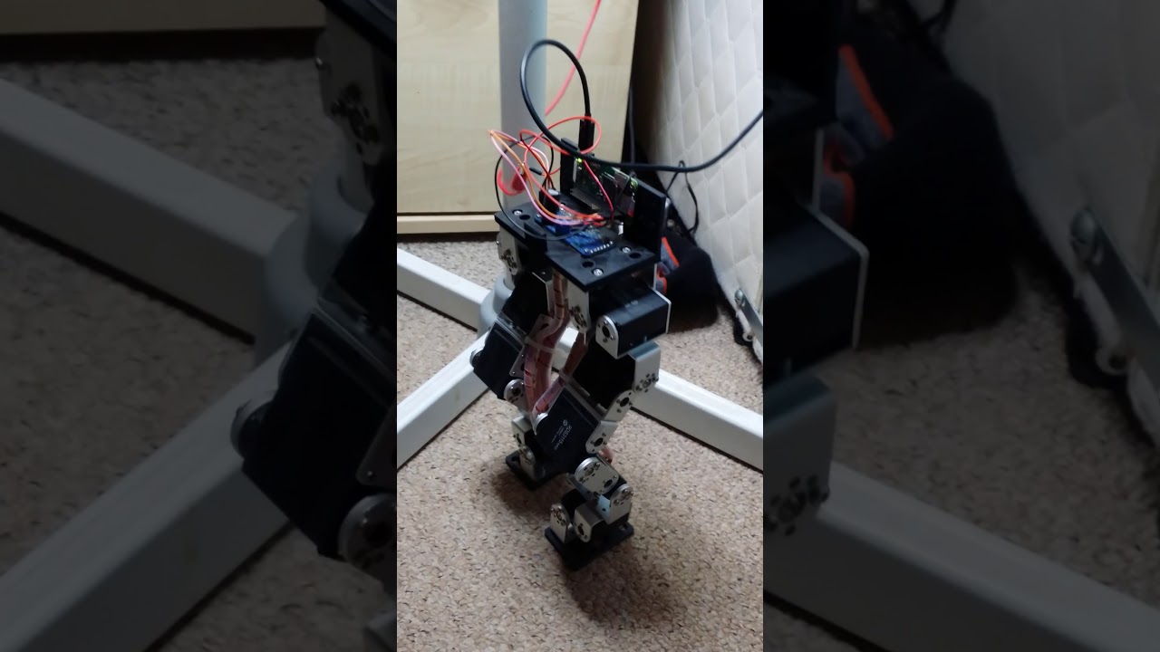
2nd test of my robot, this time stands on own running a canned push up exercise. No logic so will fall over if pushed. Just a test to see if the servos can p...
mellow carbon
OK, I had to frankenstein a 5v adapter (plug swap with a 12v one) and things work fine.
 rustic raptor
@boreal talon It looks great!
It resembles a toddler doing squats.
mellow carbon
Testing out the accel I hacked onto a Feather Crickit. Works fine.
Perk of Crickit robotics: hacking on it out on my balcony.
mellow carbon
I hacked a Flora accel breakout into a Feather Crickit.
And I hacked an ItsyBitsyM4 onto it as well.
wheat rivet
nice @mellow carbon!
 lunar gull
I wish I had money to spend
mellow carbon
In the early stages of fiddling with this.
main jolt
self-balancing biscuit whiskit?
mellow carbon
No biscuits involved. A Crickit was hacked in the process, though.
lunar gull
Speaking of crickets, I had a giant 3 inch one climbing my pant leg when I was trying to practice morse code. It scared the di-dahs out of me. I saw a black thing moving up my leg. shudder i was able to safely get the poor guy outside where he belongs
mellow carbon
Crickit crawling up your leg... were the grabbers driven by servo or solenoid?
idle valve
Hydraulics, maybe?
 junior bobcat
Anyone here a fan of combat robotics?
 chrome vigil
me
junior bobcat
Woo!
I'm currently in the process of designing one for the fall contests in the UK.
junior bobcat
It's still in CAD, and all a bit private for a moment, I'm keeping it Patreon-exclusive until it's entered. One reason is that it gives the patrons something to access before the public does, the second is this year some people have been stealing images of CADs for their robots.
I will say however, I'm hoping this will be the start of something new in CR, since it will have a semi-autonomous feature to it.
chrome vigil
ok
junior bobcat
Not many of these robots use Arduinos or Pis since they're not required, but I'd like to bring my skills into the battle.
 hasty river
looks around
 frigid perch

You can download the software I was using right here. https://bitbucket.org/heXor/neatocontrol/downloads/neatocontrol.zip
 brave bone
Funny question is there a way to flash the firmware on a cricket? I think I got aagnet from a speaker to close and wiped it
brave bone
Ok , it turned out I needed to resrty CP (double press reset) and it started working again, phew that was a close one 😂
sly sand
Just jack in as usual. You have to double-click reset to access the mode where you can update the firmware.
Magnets won't wipe the SAMD21G18A's internal flashROM.
brave bone
Thanks @sly sand I panicked, and it took a bit to get back upto speed.
sly sand
Eventually it becomes second nature and the panics don't solve anything, and so are optimized out. ;)
 midnight fable
Looking for ideas on a low cost 'junk-drawer robotics' project for a non-profit summer camp environment, 1hr assembly, suitable for ages 7-17, 4:1 camper:facilitator ratio in groups of 10 to host ~130 kids over a week period . E.g. last year we made 120 jitter-bot kits out of a flat of hobby motors with 3-D printed shaft-to-bb adapters and a whole bunch of assorted items from the dollar store (vegetable brushes made great jitter-pigs), for a cost of a few dollars apiece. Anyone done something like this at scale?
surreal elbow
@midnight fable I was just about to suggest a "bristlebot". What about using a few small hobby DC motors and cardboard to let the kids make all sorts of things?
Maybe each age group makes a small cardboard "car", and you have a sort of cardboard car derby
midnight fable
@surreal elbow thanks, yeah using the same principle but opening the gates on other types of motion and materials could be a nice spin. We also took dollar-store handheld fans and modified them a lot, but that model has been discontinued
a couple years ago we had a lot of motors that were strong enough to direct drive some small cars with gears, but there's a big difference in torque between some of the models available. The cheapest / weakest ones are best for use in bristlebots because you don't need much torque
 primal shell
I was musing on that myself while playing with the Crickit. However, since it only has 4 connections (power, ground, SCL, SDA), it wouldn't be hard at all to bodge a Trinket on there. There are two more optional connections, for audio and NeoPixel signalling) you could hook up as well if you wanted.
I read through the documentation (and on the SAMD09 Seesaw breakout) but I didn't see where the name "Seesaw" came from. Does anybody know?
sly sand
Ask Mr. Dean Miller -- he frequents one of these channels (but only one). The recent one.
Pretty sure he's the primary author of SeeSaw.
#help-with-makecode is that new channel.
I had the same question but the license suggests that limor scott and dean wrote it.
polar geyser
@primal shell you could absolutely put a trinket m0 on there, but you'd might struggle for space on it with circuitpython given all the libraries you need. arduino would work best with a trinket. for circuitpython, express boards work best with crickit
seesaw is just our name for the protocol/chip that does the i/o assist

An I2C to ... whatever! interface
primal shell
One note on the Crickit: it would be handy if the silkscreen showed the orientation of the servo connectors.
polar geyser
yeah we thought the #'s would be the indicator
primal shell
That makes sense: the other pins are all common, so the end with the numbers would be where the individual signal leads are.
The hole pattern on the purple robot chassis is tantalizingly close to lining up with the mounting holes for the Crickit. It's pretty close to lining up if I use one of the tapped holes and one of the slots, but then the only other thing that lines up is one of the capacitive touch inputs. I could use a nylon standoff there, but it's pretty close to an existing mounting hole and doesn't provide much stability. Fortunately (as the chassis notes point out), aluminum is easy enough to drill.
polar geyser
yeah i think if you dont mind being a little creative with mounting you can get it working
primal shell
Since the TT motors are out of stock, I have to be creative with mounting anyway to put continuous rotation servos in there!
sly sand
.oO( .. you know the drill .. )
sly sand
trinket cricket
primal shell
ItsyBitsy Crickit won't do?
sly sand
😕
primal shell
Come to think of it, the Crickit has a SAMD21 on it, so you could build a "headless Crickit" by reprogramming it.
Now I'm tempted to grab one of the original Trinkets and bodge it onto a Crickit. An ATtiny85 in using a much more powerful SAMD21 as a peripheral. Talk about the tail wagging the dog!
Obviously, I won't be running Circuitpython on the ATtiny85!
sly sand
@primal shell
https://github.com/wa1tnr/ainsuForth-gen-exp-crkt
Crickit (CPX variant) standalone
primal shell
Somehow I'm not really surprised someone else thought of this.
sly sand
I thought of it the day I got the crickit in my hot little hands. It's ATSAMD21G18 which is most of the SAMD21's from Adafruit.
The LED is on D37, by the way (but that's when treating it as if it were an ItsyBitsyM0, which seemed the closest match in the Arduino IDE).
NeoPixel seems to be on D39 iirc.
sly sand
https://github.com/wa1tnr/ainsuForth-gen-exp-m4
Works nicer for stand-alone. Wait-for-USB blinkies are on this one.
Apparently I updated it for crickit. I'd forgotten.
primal shell
Heh, I'm trying to talk to a Crickit with a Trinket, but the Seesaw library doesn't want to play nice with the Adafruit Wire library (aside from the "multiple libraries" issue I'm having with the Wire library). Granted, this is a silly thing to do, but now I'm wondering if the Seesaw library is even going to fit in a Trinket. I could dodge both problems by simply making the I2C calls directly.
Hmm, it does fit. For some reason, the Seesaw library explicitly refers to TwoWire instead of Wire, and the TinyWire module doesn't define that (it defines TinyM_USI_TWI).
I see the problem, the Wire libraries define a Wire object, but not a Wire type, and the Seesaw library refers to pointers by type. I could hack around it with #ifdef, but I'm trying to figure out if there's a more elegant approach (typedef acts strangely in C++).
 vagrant epoch
Hi everyone I'm new here but have a question about servos/robotics. Im looking to build something that can apply a significant amount of pressure onto the skin of a drum head but I think some of those small robotics servos would not be adequate. Can anyone suggest what kind of external components I could look at using?
primal shell
You might be able to use a lever, depending on how far the drum head moves under pressure. If you need significant deflection and pressure both, you might have to start looking at capstans or geared motors.
main jolt
@vagrant epoch could you clarify what you mean by applying a significant amount of pressure on a drum head? Is this trying to make a sound out of the drum by striking it really hard or some other thing like pressing down on it like a timpani player or something not musical related?
vagrant epoch
Thanks for the replies everyone, I'm actually looking at the possibility of both. I think striking the drum head might be easier but applying pressure to the drum head to tune it is a common 'extended technique' which I'm looking to replicate. It would just be pressing down on the skin
 austere marsh
@vagrant epoch what about using a worm drive to increase pressure by extending a pad, and use a pressure sensor to stop when enough pressure is exerted on the head?
vagrant epoch
i have no idea how to do that
but it sounds great
can you send me some info on it so i can research?
austere marsh
you'd really just need something that would extend as the worm drive turns
and there's a pressure sensor on the adafruit store, that could fit on the end of that
you'd just have to clamp the whole mechanism to the rim of the drum...but could probably use a quick-release clamp for that
but if you want to tune the head, I guess you'd need a robot that actually moves along the rim, then when it gets to a tuning nut, drops a socket onto it, so it can turn it
but not sure how that would work on say, drums where the rim isn't easily accessible e.g. kick drums
vagrant epoch
just needs to be a snare drum
austere marsh
oh cool
something that was challenging when I first started 3d printing, was a printing a drum key that wouldn't split when tuning a drum
I suspect the best way would be to have a metal ring around it, so it won't expand
so think of a can opener, where the robot would go around the rim, using a wheel on the side of the drum perhaps?
oh, there's a lot of drum tuners online I just realised
vagrant epoch
i really dont need to it to access the lugs, it just needs to apply pressure to the head of the drum to in effect lengthen it
primal shell
Basically like pressing a (robotic) thumb on the head?
 hallow pecan
this is kind of awesome (just came across the video) https://www.youtube.com/watch?v=IvUU8joBb1Q not exactly a robotic drum, but that search is what lead me to it

Get the audio track "Marble Machine" by Wintergatan: https://wintergatan.bandcamp.com/track/marble-machine Marble Machine built and composed by Martin Molin ...
vagrant epoch
@primal shell exactly!
primal shell
That gives me a useful mental model as to what you're looking for. I couldn't find a diagram that seemed close, so I doodled one up.
vagrant epoch
thats exactly what I would need
any idea how I could make it as compact as possible?
primal shell
That depends somewhat on how much pressure you need to apply, and how far the head is going to deflect when that pressure is applied. I'm thinking something like a floppy disk drive positioning motor is a pretty compact linear actuator, but might not be powerful enough for your use.
Naturally, you can use a less powerful actuator and a longer lever, but that's likely to be less compact than a stronger actuator.
wheat rivet
A couple thoughts from looking at that design: you could 1) align the motor & worm along the drum carcass and use an angled arm [Z or S shaped]. 2) instead of a worm on the Y axis, you could move a wedge on the X axis.
vagrant epoch
Would you be able to sketch that to explain it to me? I think I get it but not sure
wheat rivet
At work right now, and on phone. I could maybe slap something together later.
vagrant epoch
that would be realy appreciated!
Is this something I could build out of simple components or would it have to be really custom built/machined?
primal shell
I'm guessing you'd want to bash something together fairly quickly and cheaply for an initial proof of concept, which should be entirely possible.
This is why I tend to refer to easy to obtain stuff like positioners out of floppy disk drives instead of fancy purpose-built kit like this: https://www.portescap.com/products/can-stack-linear-actuators/20dam-k-can-stack-stepper-linear-actuator
The smallest of Portescap's miniature stepper motors, the 20DAM-K is capable of of providing 30.6N of linear force without losing power or accuracy.
vagrant epoch
is 30 N a lot of force?
primal shell
It depends on what "a lot of force" means to you. It's about 3kg.
For reference, here's a short video I made for GISHWHES of a unit I threw together to flush a toilet whenever it heard the word "Crowley". The lever arm is an ordinary carpenter's square, the pivot is the bearing from an office chair. The linear actuator is being controlled with an AdaFruit motor shield. https://www.youtube.com/watch?v=J92J7MNGA-k

Voice recognition robot flushes toilet when it hears the word "Crowley"
vagrant epoch
Id be looking at controlling it via Arduino
primal shell
The motor shield is on an Arduino, that works fine.
main jolt
@vagrant epoch Have you ever looked at Rototoms? You could probably motorize that some way. Good luck.
wheat rivet
Love playing on Rototoms. Almost added a set for Xmas last year...
vagrant epoch
I know them, just not really what I need atm
sly sand
30 N-m (Newton-Meters) is about the minimum for a greased rear wheel axle nut on a bicycle.
About half of that maxes out a small torque wrench (9" handle or so).
8 N-m is quite good for most bicycle fasteners (brake cable clamp, brake shoes &c.)
I think twice before going as high as 10 N-m on any bicycle fastener. I always look it up:
https://www.parktool.com/assets/img/repairhelp/torque.pdf
(specified in inch-pounds, not in Newton-Meters -- conversion charts are available)
That's all torque. Force is directly related to the value '30 Newtons'.
https://en.wikipedia.org/wiki/Force
https://en.wikipedia.org/wiki/Newton_(unit)
main jolt
May the Force be with you.
vagrant epoch
Cool thanks!
 magic garnet
I'm working on a project that has adafruit tt D.C. motor running on about 6 volts. The problem I'm having is that I need a motor with about 20% more torque in a package that is close to what the current motor is designed with. Any suggestions?
 cursive loom
Could someone please help me? I a newbie and still learning. I bought two of those Pololu Carrier w/ sharp Digital distance sensors. I can not figure out how to connect them to the Adafruit Feather 32u4 Bluefruit LE. Its for the robot that was in the Adabox 002. Maybe someone has a picture of how they connected theirs. I'm not sure where to connect vin and out. I know where the ground is. Any help would be great. Thanks.
primal shell
@cursive loom did you have it working before (that is, did you have the Feather 32U4 powered)?
Basically, Vin is the power supply pin for the digital distance sensor. You can hook it to the 3V pin on the Feather. the Out pin is where the sensor outputs its signal, you'd hook it to a free pin on the Feather, so the Feather can receive the data.
@magic garnet, there are several motors available in (about) that size - you can choose one with a higher gear ratio to get more torque (but at a lower speed).
magic garnet
@primal shell thank you for the reply. I've only used parts from adafruit for all my projects. I'm very new to buying from someone else. Any suggestions?
primal shell
This is sort of the same size, but I don't know offhand if it has more (or less) torque: https://www.adafruit.com/product/154

This servo rotates fully forward or backwards instead of moving to a position. You can use any servo code, hardware or library to control these servos. Good for making simple moving robots. ...
Driving it is completely different, however.
This might do too: https://www.adafruit.com/product/3802

These durable (but affordable!) gearbox motors (also known as 'TT' motors) are an easy, low-cost way to get your projects moving. This is a TT DC All-Metal Gearbox ...
cursive loom
Thank you
 scarlet bronze
Cool!
austere marsh
@primal shell pity Crowley is not around 😦 what about making it open a portal instead? 😉
midnight fable
@hallow pecan https://www.youtube.com/watch?v=C8qyVURtSZc&list=PLLLYkE3G1HED6rW-bkliHbMroHYFf4ukv tacking onto your video share about the marble machine - it's the process of designing the successor machine. Have found this playlist to be pretty engaging, for the root reason that it has Just Enough Editing. It doesn't shy away from representing what the process of invention and engineering really takes - lots of trial and error, the benefits of CAD, seeking and taking advice, etc.

So it Begins! In this first Episode i wanted to try to describe as many functions as possible of the M.M.X to all the engineers who are emailing me and want ...
hallow pecan
nice!
midnight fable
To be fair, #9 is probably the best one to start with
hallow pecan
it's cool that it's being built now, with the last post being wednesday
midnight fable
Yeah when they take it on tour I'll be keeping an eye out - would be pretty cool to go to a show.
 velvet ridge
@here I expect this might be relevant to people's interest in robotics and music: https://www.youtube.com/watch?v=9gMX_hR-RoM

Hey Meatbags ! Here you go, just what you've all been waiting for... Meet "Mega-Wattson" the new singer and "Hellga Tarr" the new guitarist and backing vocal...
Compressorhead, the pneumatically driven heavy metal band.
wheat rivet
@tall nacelle i would ask in the #help-with-radio channel. though someone may venture over from there, eventually.
 short plank
If I was wanting to make a robot that had a part that moved along a rail, like a 3d printer carriage does, what is that part called? I can't figure out what to look up. 😄
surreal elbow
@short plank I think it would depend on the function of the part, but a carriage may be a good starting point.
what are you trying to do?
short plank
Something that's been done a billion times, but I want to reinvent the wheel for fun. A whiteboard writing robot. Figure it'll work with CNC style gcode.
Wanted to do one that actually moved up and down on rails rather than hanging from lines.
surreal elbow
Have you looked at the "drawbot" examples? They mostly use linear rods, but could be adapted to rails
short plank
linear rods might be the actual name of the thing I'm looking for.
😄
I kept looking for rails and finding the wrong things.
surreal elbow

Homemade Axi Draw Bot 4xiDraw Robotic Pen AxiDraw DIY Robot 3D Printer Plotter CNC Laser Drawing X Y Z Axis Art Plotter Laser Cutter Engraving Arduino
short plank
Yep, that's exactly what I want. Thanks!
surreal elbow
that one uses a laser, but a servo and a felt pen would be just as easy. Google "drawbot"...you'll get loads of builds.
short plank
Yep, I did. Super helpful, thanks
sly sand
Hi all, can someone explain w/ a simple sketch how to connect ATTINY84 to a DC motor using a H-BRIDGE like L293D ? Thank you
primal shell
It's pretty simple. Choose two I/O pins (I'll use 2 and 3 for this example) and connect them to two of the inputs of the L293 (perhaps pins 2 and 7). Tie the corresponding enable pin (pin 1) high for now.
Connect the motor to the outputs of the L293 (pins 3 and 6).
In the sketch, make the pins you chose outputs:
pinMode(3, OUTPUT);
Then, to turn the motor one way, set one high and one low:
digitalWrite(3, LOW);
To run the motor the other way, swap them:
digitalWrite(3, HIGH);```Once you have that working, you can add other goodies like controlling the motor speed. To do that, choose an I/O pin with PWM capability and hook the enable lead of the L293 to it. Make that pin an output, then use analogWrite() to that pin to change the motor speed.
Note: hook Vcc1 (pin 16) of the L293 to the same +5V supply as your ATtiny84. Hook Vcc2 (pin 8) of the L293 to the motor power supply. Connect all the grounds (both supplies and pins 4,5,12, and 13 of the L293) together.
sly sand
Thanks a lot @primal shell
mellow carbon
Any comments on using the 6600 mAh LiPo and the PowerBoost 1000 to power a CRICKET with a couple TT motors? I had issues using 3xAA (alkaline): when the bot got stuck and the motors stalled the CPX would get into a bad state (aborting into the repl). The LiPo boost can handle the current in that situation and can alert the CPX of the situation, allowing it to turn off the motors and call for help. However in the CRICKIT power section of the guides it advises not using LiPo (due to the voltage mismatch from what I read).
primal shell
It seems to me that might work, if the boost really can handle the current draw with both motors stalled. Normally I try to power my motors and logic separately to avoid just such situations. The Crickit page recommends 3 cells if you're using alkaline ones.
primal shell
The page also says you can plug the USB into the CPU board "to program it". I wonder if you could also supply backup power that way (say, a MiniBoost for the CPU and let the rest run from the battery).
I think you read it right: it's suggesting not using LiPo directly, because 1 is not enough voltage and 2 is too much. If the PowerBoost can manage the current draw, it seems like a reasonable solution to me.
mellow carbon
Agreed regarding separate supplies. CRICKIT is for hobbiests, though.
Good... because it works beautifully.
primal shell
True, if I'm building a big heavy robot using wheelchair motors, I'm not going to be powering them with a Crickit.
mellow carbon
With this cell fully charged, it will spin the wheels if it gets stuck. That's soft rubber on laminate flooring... pretty good traction.
I'm curious what the wide orange wheels will do. I'm assuming they have more grip.
primal shell
Now I'm curious too – if you try them, let us know what happens.
mellow carbon
I will. I'm aldo curious about what it will do on inclines.
primal shell
Inclines are fun, especially if you're trying to keep to a straight path when traversing the incline diagonally.
mellow carbon
This bot is very simple, no feedback. The tank I'm working on will use encoders.
Orange wheels don't break free as easily.
It'd be really nice to have interrupts 😃
primal shell
I ended up using interrupts for encoders, but had enough slippage that I went on to playing with an IMU.
mellow carbon
My tank will have that was well.
primal shell
Sweet! That turned out to be much more complex than I expected.
mellow carbon
Encoder feedback will be mainly for speed matching between the motors.
To try an keep a straight course.
It's still very much in the planning phase as far as the electronics go.
I'm using this as the chassis. https://www.thingiverse.com/thing:652851
The second prototype out of the jRobot project, this little tank bot makes use of a number of simple parts to do a whole lot.
I have updated it to make it more versatile. The tracks are a little more grippy as well!
https://www.youtube.com/watch?v=MJIx0cyOL3s&feature=yout...
primal shell
Nice! I started with that two-wheeler with roller ball then moved on to a Zumo style chassis.
mellow carbon
Not enough room inside for crickit & battery, so it'll be a Feather M4 and wings on a doubler.
This design is nice in that there is an inset around the top opening, making it easy to design addons.
primal shell
It looks sturdy and fairly æsthetic as well, which is nice.
mellow carbon
The holes on the front and back will work for sensors: light, possibly a laser time of flight distance sensor.
primal shell
Not Pixy 2?
mellow carbon
I'll be using the blue TTs with metal gearing so a mic if probably pointless.
hallow pecan
matching speeds on two different motors seems to be an interesting mathematical question, especially at less than 100% speed
primal shell
The approach I took was to slow down the faster motor until it matched the speed of the slower motor.
mellow carbon
The pixy2 look too big to be inside. It could go on the roof.
First step is an autonomous motorized platform.
hallow pecan
@primal shell if you wanted to run at, say 80% would it still be 80% of slower motor with the faster running at a slightly less percentage?
primal shell
Yeah, that's how I implemented it. I'd just multiply the desired speed (like 80%) by the correction factors (such as 1 for the slower motor and 0.93 for the faster one).
hallow pecan
nice
primal shell
That's when I decided "this is not complicated and painful enough" and decided to use a PID algorithm to try to match the commanded and actual speeds, using the encoders for feedback. Talk about going down a rabbit hole!
primal shell
Ah, the sane "get it working so I can concentrate on something real" approach. Alas, not the approach I chose.
mellow carbon
Different bot
mellow carbon
Stretched the width of the tank body a bit so as to fit a CRICKIT.
 real patrol
Here's a work in progress I planned to try and finish up this weekend (better centroid tracking + publishing to pip) that some of you might be interested in for robotics. https://github.com/hlfshell/personable

human tracking in python for projects
(skeletal pose tracking, frame by frame movement, and facial recognition for knowing whom youre looking at)
 haughty iris
@mellow carbon Have you considered NIMH batteries? They are my choice.
Wow didn’t even realize you guys were talking about that long ago.
mellow carbon
@haughty iris I’m favouring LiPos these days primarily for the variety in shape/size/power as well as the bundled charging options (e.g. on feathers or the boost boards)
sly sand
NiMH is the way to go if you don't need the extra capabilities (esp. form factor!) of LiPo.
Somebody here bothered to 3-D print a proper LiPo protective case for a project.
That's very smart.
hallow pecan
Not limited to robotics, but could be applicable. Has anyone implemented torque limited motors? For uses like finding max/min range
primal shell
I have a tape drive that does that.
hallow pecan
@primal shell I assume that it came that way
primal shell
Yes, when it gets reset, it runs the head positioning motor for a while, letting it bang against the stop, then it knows the head position without needing a sensor.
hallow pecan
🤔
hallow pecan
so a dc motor which is stalled sees a spike in in current, could i use that to signal an arduino to assume the limit is reached?
primal shell
Yes, that's doable. Some motor driver chips will do it for you.
haughty iris
Crickit fits great on this chassis.
 sacred fulcrum
Hey. That looks slick
sly sand
^
 craggy condor
🤖👍
 green girder
Hi all, I have a question about the Crickit. I'm playing with the adabox008, and have a small bot put together that uses the H-bridges to drive the two gear motors with wheels attached. I've noticed that when it hits something it looks like the motor current draw is causing the CircuitPython code to error out. I think I could work around this in a non H-bridge setup using transistors, but I'm not sure how to protect the board when I'm using the H-bridges. Does anyone know how where I might look to learn how to deal with that?
mellow carbon
@green girder I saw the same thing when I was working on my “snake bot” guide. My conclusion was that it was the combination of the use of alkaline AAs and the use of the same batteries for both the motors and the electronics (although I’m not a power systems engineer, so I might be wrong). My solution was to switch to the 6600mAh LiPo and the boost1000C board which worked great. It’s beefier and has a low voltage signal that the CPX can monitor and react to.
green girder
@mellow carbon thanks for the tip. I guess I wildly underestimated how much current those little gear motors draw.
mellow carbon
@green girder Stall current can be pretty high.
 willow geyser
anyone know how to level shift the adalogger GPIO pins to 5v? I'm trying to control a motor driver ... but it needs 5V logic levels and my pin seems to be high at 2V instead of the expected 3V.... so my old level shifter isn't shifting the signal to 5v...
velvet ridge
Hello?
velvet ridge
@green girder @mellow carbon I'm having a Cricket issue also.
Though in my case, maybe I've done something obviously wrong.
green girder
@mellow carbon BTW thanks for the tip, that fixed it. I just grabbed a lipoly from another project and added it to the CPX and problem solved.
velvet ridge
I mounted the CircuitPython board to the Cricket, plugged the battery pack into the Cricket board, and got the blinking red <!> LED.
mellow carbon
@green girder Good to hear.
velvet ridge
Nothing further. Is it undervoltage? I thought the Cricket would be OK with the 4.77 I'm getting out of the three AA's in there. Do I need to go get a power supply?
mellow carbon
@velvet ridge It should be ok with 3 reasonably fresh alkaline AAs.
velvet ridge
I'm using the ones from the Adabox, they meter out to 4.77 V.
mellow carbon
Should be fine
velvet ridge
I haven't tried to pull a current from them.
Do I need to separately power the CircuitPython?
CircuitPlayground Express?
mellow carbon
CRICKIT has a "bad voltage" light by the power switch
velvet ridge
Is it throwing an error because of that.
Right, the blinking red LED that goes off.
mellow carbon
No, I'll get power from the crickit
mellow carbon
Yellow I think
no.. red
yes. green is power on, red is power voltage out of range
velvet ridge
And the red one is the one that I'm getting.
So, 4.77V is too low, then, I take it?
So I should get a regulated supply at 5V.
I think I can make that happen with parts I have on hand.
I don't happen to have a power adaptor handy that delivers that to a 2.1mm jack.
mellow carbon
Well, 3 AAs should x. 4v5k nominally
mellow carbon
Carefull of the current. Depending what you have hooked u, you might need a few amps.
Yeah, it should be ok.
Measure the voltage actually being delivered to the board. might be a poor wire or connection.
velvet ridge
All that's hooked up right now is the CPE on top of the brass stand-offs to the Cricket.
No motors no nothing.
Is this the blink program blinking the wrong LED?
velvet ridge
I took the battery pack, and plugged it into a 2.1mm female jack that went out to screw terminals, and measured the voltage across the two screw terminals.
So, if there's a bad connection, it's not in the battery pack.
hmmm.
I guess more things to meter later.
But for it to be blinking an LED at all, it must have a complete circuit back to the battery pack.
Thanks for your help, I'm AFK a while to go get dinner.
mellow carbon
Hmmm... If I plug 9v into a crickit the red light comes on solid (i.e. with the triangle/warning icon next to the power switch)
velvet ridge
Yeah, that's a significant overvoltage.
velvet ridge
MURPHY'S LAW STRIKES AGAIN
I mounted the CPE backwards.
If I would have Read the FM, I probably wouldn't have done it wrong in the first place.
@mellow carbon thanks for you attempt at help.
mellow carbon
Yeah... that would cause problems. I still make a point of doub;le checkign the pad labels before bolting it on.
velvet ridge
If anybody is interested, I'm pushing code I come up with to https://github.com/pcurry/adabox008

GitHub
adabox008 - Code I write while playing with Adabox008. May include code from Adafruit tutorials.
@mellow carbon yeah, I lambasted myself as a fool when I looked at the pad labels screen printed on the boards.
mellow carbon
It happens.
velvet ridge
It just made sense to me to match the power and USB connectors on the top and bottom boards.
mellow carbon
That a nice thing about the Feather version 😃
velvet ridge
Heh. And I already have at least one M0 Feather.
mellow carbon
One way to think about it is having all external connection at one end: power & USB.
You'll hardly ever use the crickit's usb.
velvet ridge
Yeah, I don't expect to be debugging seesaw.
Though, it shows you a difference in mental habits.
My brother is a Mech. E. from RPI - Class of 2001 or 2002.
I told him about my debugging process on these boards, and my looking for answers here.
He suggested I try to get an RMA because it was obviously a defective board.
I said I'd look again, because as a programmer, when something breaks, it's almost always your fault.
Until you've proven that all of your code is perfect, you don't blame the libraries, or the compiler.
mellow carbon
Adafruit products are solid. The only RMA I've needed was something that got crushed in shipping. Nothing else has had a problem. And I've gotten a lot of things from them over the past 5ish years.
velvet ridge
That too, but that was more a contributing thought than my trained impulse.
mellow carbon
Yes, toolchains are pretty good now. I remember when you were often right when you blamed the compiler 😃
velvet ridge
Well, like as not, you were working on the compiler.
I mean, I can't remember the last time Clang or GCC was the problem with code I was using.
mellow carbon
Exactly. I'm thinking of pre-gcc days.
velvet ridge
Right.
I find it really comforting to be reminded that some things are in fact getting better.
sly sand
when was pre gcc? 1980s?
velvet ridge
And earlier, yes.
Pre-GNU would be pre-GCC. And early GCC was a labor of love, I'm given to understand.
 compact copper
I was wondering if anyone here has worked with air bearing pucks?
velvet ridge
no, but I've seen some lovely applications.
 hallow drum
Hi, I'm making a rover cat toy using a CPX and Crickit. Using a VL6180x sensor and two motors everything works but when i add a second VL sensor none of the sensors work. Is there any code that shows how to use multiple sensors on the SDA/SCL lines?
primal shell
You can use multiple sensors, but there are two things to watch out for. The obvious one is that things need to be at different addresses. The less-obvious one is that you need exactly one set of pull-up resistors.
Unfortunately, that sensor doesn't have a changeable address, it's fixed at 0x29.
There are a couple of ways of working around that. One is to move it to a different set of SCL and SDA leads (if your controller doesn't have another I2C port, you can use software I2C).
The other is to use an I2C multiplexer like a TCA9548A to split your bus into multiple buses. You have to modify your code a little to tell the chip which bus you want to talk to before you send a command.
 sterile silo
Good evening. 😃 I was wondering which of the Feather boards is the most capable but that runs CircuitPython. I want to use it in conjunction with the PID 3343 Cricket to make a robotics project. Actually more specifically, a miniature prototype of a low cost, open source power-chair that I am working on the design for and am working twords producing.
Additionally, does anyone know where I can find either an Autodesk Eagle file, or a STL file of a Feather Cricket? I want to use it to integrate the Cricket into the mini-protoptype frame design.
sly sand
There aren't that many express feathers. There's the hallowing and the M0, and there's the M4, which I expect is the most capable one. https://www.adafruit.com/product/3857

It's what you've been waiting for, the Feather M4 Express featuring ATSAMD51. This Feather is fast like a swift, smart like an owl, strong like a ox-bird (it's half ox, half ...
The guides to most of adafruit's projects is where you can find Eagle files. (From the product page follow the link to the "learn about <productname>". In the guide click on "downloads". For the M4 feather that'd be https://learn.adafruit.com/adafruit-feather-m4-express-atsamd51/downloads -- and on that page is a link to github where Eagle files are on offer. This basic organisation holds true for most Adafruit designed products.)

This Feather is fast like a swift, smart like an owl, strong like a ox-bird
sterile silo
Awesome, Thanks @sly sand
sterile silo
Does anyone have any experience working with omnidirectional or mecanum wheels?
turbid trail
@sterile silo the CPX is an Express board too, though not Feather shaped, and of course it has its Crickit. It's the same parts as a Feather M0 Express plus all the on-board extras: the accelerometer, neopixels, etc. may be of use to you.
primal shell
I've seen the omni wheels, but never got a chance to play with them. They use angled rollers to allow moving in various directions by combining drive motions in various ways.
sterile silo
Good morning @turbid trail . O ya, before my landlord stole and trashed most all of our stuff my daughter and I had two CPX's. Mia got a CPX advanced pack for her birthday last September, so trust me I know just how awesome the CPX is. We had SO much fun learning and playing with them. 😄 I was thinking of using the Feather in the prototype model because that's what I'm thinking of having in the full size CirciutPython powed, open source powerchair, a Feather and a super powered, 150 Amp version of the Cricket. 😃 But you know what, I think that the prototype powerchair should have a CPX powering it. Really miss having that little board to learn and play with. Thanks for inspiring me to think about this @turbid trail 😃
Ya, thanks @primal shell . I was wondering if anyone knew what the ride quality was like on omni-wheels. Thinking of using them in my open source powerchair design.
primal shell
That would make a cool powerchair, with the ability for sideways motion. My guess would be that it would be a little bumpy, but I don't really know for sure. I can imagine that it's possible for real smoothness with carefully calculated tapers and angles, but I don't know what the commercially available possibilities are.
sterile silo
Ya @primal shell , that's what I was thinking (hoping) with the carefully selected tapering of the wheels that might be able to work. As far as the marketability, I'm not looking to make a mint or anything or directly compete with other powerchair manufactures. I designed this with helping people in mind. Having gone over a decade with my own body not always working right and not always being able to get to the places that I needed to go to, or take my daughter to the places that she wanted to go. Just because I didn't know if I'd be able to keep walking, or if my body would keep functioning adequately. I know what it is to not have the needed mobility. My inspiration with this is to help others that might have faced the same or similar challenges that I faced, so maybe they wont have to face quite so many of those challenges anymore. This is to be a kind of 'mobility for the masses' not just the people that can afford to brake the bank to afford to buy one; you know?
primal shell
I totally get that. I've worked on some niche projects to help people with disabilities, but yours could help a great many people – that's excellent.
velvet ridge
I'm looking at the bits and pieces I have around, and I think I can make a small Cylon rover.
I have a pan-tilt kit for micro servos (unassembled), plus Adabox008, plus some extra micro servos, plus the Adafruit-Digikey racecar box, plus a Larson Scanner kit, plus a hackerbox kit that does facial recognition.
Now I just need to get the audio for "by your command" and the scanning sound.
primal shell
That sounds cool, even if it doesn't entirely qualify as "build robot friend".
 cosmic badger
Anyone wana help with some custom code for a robot? I'm making a YouTube vide
I don't have any of the experience required for making this project
NVM
velvet ridge
I made a cool little animation of a smile on my Circuit Playground.
Adabox 008
Because of my coding habits, there's a couple of helper functions rather than things being done in-line.
You can find it here: https://github.com/pcurry/adabox008
GitHub
Code I write while playing with Adabox008. May include code from Adafruit tutorials. - pcurry/adabox008
The smile animation should generalize to larger neopixel rings - you just need to give it a number of pixels to separate the eye from the centerline on each side. It then grows the smile symmetrically.
wheat rivet
@mellow carbon looks like ROS on RPi is doable. like i said, i was reading about ROS for the first time today, so i am not sure how it could/would mesh with Crickit use. http://wiki.ros.org/ROSberryPi/Installing ROS Kinetic on the Raspberry Pi
mellow carbon
I've looked at ROS before. It's basically the communication/process infrastructure (not unlike MQTT, but with more process tools). As for CRICKIT, you'd just make use of it as required in the processes running on ROS. You should be able to avoid contention (e.g. for use of an input/output) by paying attention to resource allocation in the design.
wheat rivet
heh. i was thinking MQTT while reading about it (anonymous messaging system, were their words iirc).
mellow carbon
Yeah.. looks liek straightforward pup-sub. The cool bit is the process management, though.
They need to communicate.. so the MQTT-like pup-sub.
It'll be fun to play with, for sure.
sterile silo
Will the Feedback 360 Degree - High Speed Continuous Rotation Servo
PRODUCT ID: 3614 work with a CPX Cricket? Can the the Cricket read the signal from the feed back wire so it can track the position?
Like for instance, could I plug the signal wire into one of the signal IO ports?
Or would I be better off only using Continuous Rotation Servo - FeeTech FS5103R
PRODUCT ID: 154? Which doesn't have any positional feed back.
sterile silo
And you know what, for this project, I don't think specific positional tracking will really be needed. So I'll just go for the regular PID - 154 servo's. But I am still curious for future reference as to whether or not the Cricket can handle that feed back.
mellow carbon
Anyone have any thoughts on replacing the barrel connector on the Crickit with a screw block? It's be great to have an option that doesn't stick out so much sometimes. A 2 connection terminal block that could replace the barrel connector as a simple part swap would be perfect.
sterile silo
That is a really good idea @mellow carbon .
sterile silo
@mellow carbon You could try Digikey part number ED11155-ND or part number 952-1776-ND. Either one looks like it could easily handle the power that would other wise be going through the barrel connector. The first one, the ED11155-ND looks like you could even pretty easy snip it into 2 pieces and more conveniently solder them to the positive & negative. You could probably even snip ED11155-ND in half & solder one to positive & other to negative having them lay flat against the bottom on the Cricket n use a little liquid tape to cover them up and better secure them. That way you still have use of your barrel jack when you want to. 😃
mellow carbon
I was thinking of something a little more robust. Somethin like the CRICKIT speaker connector.
sterile silo
These aere pretty robust. I don't know the specs on the speaker connector but
2 Position Receptacle Connector Through Hole
2 Position Receptacle Connector 0.100
You may want to read the specs of these @mellow carbon before deciding.
But the choice is obviously yours. When you decide, I'd love to know, cause I think it's good idea.
mellow carbon
My concern is how robust the physical connection is given that on a robot there could be significant motion and vibration. That’s why I was think of a screw/clamp style of terminal block. E.g. same as the power connector on Adafruit’s 8-servo boards.
sterile silo
Very true @mellow carbon . Vibration and wear and tear deff should be kept in mind. Though ones like that, how is it going to fit the space, (fit into the foot print, the contacts designed for the barrel jack) on the board? Speaking of vibration, I wonder how well they're going to solder in with how close the pegs are to one another on the part, as opposed to the positioning of the contacts on the board for the barrel connector.
mellow carbon
@sterile silo That, I don’t know. The simplest thing to do is just solder onto the bottom of the crickit. It’ll only be an issue in situations where space is limited. I have one robot in the works where that’s the case. In another the plug and wire sticks out the side and looks bad, as well as being at risk of getting snagged by legs.
sterile silo
Ah @mellow carbon , but that's why I like the idea of using the ED11155-ND. It, cut into they, could be soldered to the bottom, laying flat against the bottom of the Cricket. They would add only a very small amount of needed space while adding the benefits of it. I personally think the risk of the connection falling out from vibration is low, unless you were going to put it together for long term use, in which case just a dab or two of hot glue would hold the wires in place.
sterile silo
That's a great looking bot @frigid perch ! Would love to see a vid of it in action, or better yet bring it on show & tell. 😃
frigid perch
How do I bring it to show and tell? @sterile silo
Hello all! I am Noah Schreiber the leader of Schriebotics a discord server dedicated to robotics. This server is a lot of fun and my best friends are on there. We have presently 330 members on there. Although mechanical is like our bread and butter there are a ton of software and ROS gurus waiting to meet more people of similar interest. Enjoy! https://discord.gg/NJXSGfZ
sterile silo
Every Wednesday night at 7:30 pm Eastern Standard time Adafruit, the owner of this Discord server, hosts an electronics show & tell. Here's a link:

Have an amazing project that you want to show to Adafruit? Here's how to get added to the Show and Tell Circle on Google+
@frigid perch Whether you have something to show that week or not the show & tell's are a lot of fun to watch and participate in the Discord chat at the same time. And after the show & tell, Limor (the company owner) and Phil host an Ask an Engineer show that's informative, and you can even ask Limor, 'the Engineer' questions about electronics stuff. Lol, they even do a call in at the end of the show in where you can win something.
frigid perch
Thanks!
sterile silo
No problem. Happy to help.
mellow carbon
Ask an Engineer also includes new product announcements, demos, and discussion. And often peeks at upcoming products.
sterile silo
Thanks @mellow carbon I forgot to mention all of that. 😃
sterile silo
@pine fable (awesome handle BTW) I'm watching the feed from the Circuit Python weekly meeting & just saw your post about intentions on writing a guild on how to mash up Adafruit & other open source boards. Could you please keep me in mind on any progress that you have on this project? I am in the process of working out design & plans for producing a low cost open source, customize-able and fully upgradeable powerchair for the AT community & one of the things I would very much love to have as part of the final product is a Circuit Python based controller with a seriously beefed up version of the Cricket (like a 100 to 150Amp capable) to drive the motors. So you can see how and why I am very excited that you are interested & willing to do that particular kind of guild. I don't know what, but if I can help you please don't hesitate to ask.
primal shell
So, even bigger than the RageBridge? https://www.adafruit.com/product/3567

RageBridge 2 from Equals Zero Designs is a no-frills and robust dual-channel DC motor controller for robotic and vehicular drivetrain applications. It can supply 40 amps per side ...
sterile silo
Yup, though I think it would be better for each unit to only be single channel. Presumably, a single channel motor controller would be cheaper then a dual channel. IE, say a chair's owner blows out the right rear motor controller, they would only have to pay to replace that one controller instead of paying that much more for a new 2 channel controller board.
Whole purpose of this is to not only make the base unit as affordable as possible, but also keep the repair & up keep as affordable as possible too.
primal shell
Weirdly, motor controllers seem to come in pairs. This one is 2x60A for $200: http://www.robotmarketplace.com/products/0-r0414.html

The Robot MarketPlace
The RoboClaw 2x60 Amp motor controller is an extremely efficient, versatile, dual channel synchronous regenerative motor controller.
Maybe I should start scribbling out a single-channel, open source modular motor driver.
The RageBridge is a fairly textbook design: ATmega328 for control, A3941 gate drivers, paralleled (with balancing resistors) IRFS7530 drive MOSFETs, and ACS712 current monitors.
Wouldn't be too hard to connectorize the driver portion so the power chair owner could swap it fairly easily. I'd skip the fancy through-board heatsinking and go with a conventional one. Maybe offer the modules with heatsinks for those who want plug and play, and without for the more technically minded users who want to save a few bucks by re-using the existing heatsinks when they replace a driver module.
sterile silo
If you would be willing, that would be really awesome. Thank you. Though it has to have a emergency cut off build it, cause mind you this would be used for a disabled person to ride on. As I understand, there is a whole list of criteria that a chair has to meet in order to be legally acceptable & I'm not sure what all criteria there is for the electronics. That's a really great idea!
primal shell
I'd want an emergency shutoff anyway for any high-powered electronics. A for-real shutoff too, not an electronic "please cut off power" signal that might get ignored by a controller off in the weeds.
Since higher currents are achieved by simply paralleling more MOSFETs, it's easy enough to make lower-current versions using the same board by omitting some MOSFETs.
sterile silo
Makes sense.
primal shell
http://accelerated-systems.com offers some nice modules too. My tractor uses two of their 75A modules for the traction motors and it gets around pretty well.
Which leads to a question: do you prefer brushed or brushless motors?
Hmm, the ODrive is $119, offers 2 motor channels of 100A apiece, and is open source!
There's also VESC, Benjamin Vedder's open source Electronic Speed Controller. There's some seriously cool work being done out there.
I'm still wondering about your earlier question about whether omniwheels are sufficiently smooth riding.
sterile silo
I've settled that the omni-wheels should be doable, given the vehicles that I seen using them, robots, fork lifts, & even power chairs. As for the motors
oops. didn't intend to send that yet.
I've settled that the omni-wheels should be doable, given the vehicles that I've seen in videos using them, robots, fork lifts, & even power chairs. As for the motors, brushed or not. I'm not sure what typically come with power chairs. Though if I had to guess I'd say brushless given that torque is more needed then speed. That is cool, I handn't heard about an open source speed controller being made.
50 A continuous 240A peak from a 40mm by 60mm board? Doesn't seam safe nor reliably doable to me. Mind you, I'm still a novas when it comes to electronics yet, but still.
@primal shell
primal shell
Whether you go for brushed or brushless, I'm guessing it would work best to have the motors geared down. I tend to think of brushless as the high-speed motors used in things like drones, but my tractor motors are brushless and give beautiful control. I have no idea what's typical for power chairs either.
Modern MOSFETs have some impressive ratings, but that sort of thing is why I lean toward traditional transistors-bolted-to-heatsinks assemblies rather than fancy aluminum boards with transistor tabs soldered to them.
Brushed motors are easier to control and wire (2 leads, 4 transistors), brushless motors give you more direct control but more complexity (3 wires and 6 transistors minimum, motors with integrated position sensors can have more).
sterile silo
Was just reading through Ben's open source ESC, admittedly most of the stuff is over my head but it definitely looks pretty cool.
primal shell
I would advise motors with integrated position sensors if you're going with brushless. The ones without sensors have to use the motor windings to figure out the phase, which they do by blipping the motor briefly and monitoring the resulting voltages. This would be annoying for a human rider.
There is rather a lot going on with brushless motors (as you've read). I would not want to roll my own from the ground up, which is why the existing open source implementations are a very appealing starting point.
sterile silo
Ya the more I read what you wrote, the more I'm pretty sure that brushed motors are used. # 1 reason, every chair I've looked at only had 4 wires going to it, 2 for the motor & 2 for the brake.
I think I'll stick with what is already used, the brushed motors, cheaper ( both for the motor & the need for added stuff to ake them work acceptably) & more commonly available, and consequently hopefully lower in cost.
primal shell
Makes sense. Brushed motors are simple, predictable, reliable, and easily obtained.
If you want to get fancy, you can add a position and/or speed encoder to a brushed motor, but it's not necessary. I'm guessing the chair operator will know which direction they want to go, and how fast.
Or to put it another way, you can skip lots of complicated control theory by putting a human in the feedback loop.
sterile silo
Exactly! 😃
Either the rider or a caregiver will be in control of direction & speed.
 elder lily

First attempt making a fixed wing Drone from scratch. The initial flight ended up being a failure and the airframe was too heavy for the tiny brushed motors ...
Project I'm picking back up.
Archive of my progress on it if you want to check it out
sterile silo
That's an interesting looking project @elder lily good looking plane! If your interested in getting more air time, (using less power) Have you considered increasing the wing size & span? Possibly increase it's ability to glide & use less power, thus allowing longer flight times? Mind you, I'm, by no means any kind of expert but I think that's how it's done.
mellow carbon
@wheat rivet You mentioned running ROS on the RPi... I was thinking about that this morning as I was looking at teasers of the Crickit PiHat. That's going to be a fun combo.
 dire adder
Good afternoon! I'm new to the microcontroller diy scene and I have a project in mind, but I'm not sure what I need.
I want to create a custom computer game controller using a cardboard steering wheel and dash. I figured I would get a Teensy 3.2 and use a gyro sensor on the steering wheel, but I haven't figured out which one to get.
 livid stirrup
you might do better with an accelerometer for the steering wheel. it can sense orientation, unlike a gyro.
dire adder
Ah. I'm glad I asked. I've noticed that several sensors come with both gyros and accelerometers.
livid stirrup
but a large sturdy potentiometer would also work if attached to the steering wheel column.
dire adder
In my mind, I thought accelerometers could mostly tell movement in lateral directions, wheras a gyro would know if it twisted.
livid stirrup
gyros are great at sensing motion, but an acc can sense orientation because it acaully can sense gravity
dire adder
I was trying to avoid attaching a potentiomenter to the column, as the wheel is not well mounted (it's basically a cardboard toy for my kiddo). It's likely to get pushed and yanked in all directions.
livid stirrup
I just got a circuit playground in the mail. It's got an onboard acc
dire adder
hmmm... does it connect easily to a pc via USB to serve as a game controller?
livid stirrup
not sure if it would suit for orientation sensing though.
dire adder
gotcha.
livid stirrup
yeah, easy usb connection.
dire adder
Hmm... I'mma pull up more info on it.
BTW- thank you for helping me out. I was feeling a bit lost 😛
livid stirrup
according to the makecode interface, it should be able to sense tilt
dire adder
Oh- yeah. It has an ATmega32u4. That one supports native USB.
 lone sun
is it hard to create a quadruped walk cycle with three servos per leg?
primal shell
If you're using a Teensy to start with, you might consider using a Prop Shield to easily add both an accelerometer and gyro. https://www.adafruit.com/product/3085
@lone sun it's not too tough (a "creep" gait is the easiest one to start with), but to get it to work smoothly, you'll have to deal with the intricacies of "inverse kinematics".
primal shell
It's a series of motions designed so the quadruped is always stable over 3 of the legs while moving the fourth.
Good short description here https://tote.readthedocs.io/en/latest/gait.html
The PDF on this page covers movement in detail. It's instructions for a nice little robot, the movement details start on page 49 ("Movement") and start getting into coördinate transformations and 3D leg models a few pages later: https://www.sunfounder.com/learn/category/Quadruped-Crawling-Robot-Kit-V2-for-Arduino.html
elder lily
@sterile silo That plane has since been retired. I've been working on a new air frame and recently picked the project back up.
sterile silo
Cool @elder lily . Oo wow. nice design!
elder lily
Lifting surface to mass ratio might still be kind of off for gliding, but the plane does glide well with the cg in the right spot and no electronics
sterile silo
@elder lily But you need the electronics.
Just clicked back to see if anyone posted sense I looked last & I am really loving the lines of your plane! Great job!
elder lily
@sterile silo the electronics will come, lol. I have to finish the V2 transmitter before finishing the plane... Or I'll be forcing myself to fly the new plane with the transmitter shown in the video further up. (V1)
Also, I'm posting developmental progress on my discord channel if you want to have a look. Link is posted further up ^
sterile silo
Makes sense. I will, I'll scroll up n find the link. You know, why don't you come on Show & Tell next week & show it off?
elder lily
Show and tell? I'm not familiar, is that a an adafruit thing?
sterile silo
I found the link & joined but didn't see anything about the plane
Adafruit Show & Tell, They have it every Wednesday at 7:30p Eastern Standard time. You can go on & show off what ever your working on.
Here's a link to tonight Show & Tell. Give you an idea.

Visit the Adafruit shop online - http://www.adafruit.com ----------------------------------------- LIVE CHAT IS HERE! http://adafru.it/discord https://plus.g...
elder lily
I may look into that once I get further along. I didn't causing putting the plane together as the plane is older than the discord channel. A buddy suggested making a channel afterwords to track progress so I did, but as I said I've shifted focus to the transmitter and working through the frustrations of the Nordic NRF24L01
sterile silo
They do the Show & tell & also have a live chat during the show here on Adafruit Discord in the #livebroadcast link.
elder lily
That sounds like a great way to get ideas and inspiration from others
sterile silo
Not sure if anyone in the community has worked with those or not, but you could post in 'project help' & ask. You never know.
elder lily
I think there's a radio channel that might be promising. I want to exhausted my resources (internet and datasheet) to see if I can come up with a resolution myself first.
sterile silo
Makes sense.
elder lily
Also have a semi priming 3d printed quad project going on in the channel as well.
It's all put on hold for this transmitter, lol
sterile silo
Found your projects listings. I like your Quad layout, it's different from the typical style. 😃 Looking forward to see the new transmitter progress.
O and point of thought @elder lily . Scott the first guy that showed on show & tell tonight, tannewt on here. He actually designed & produced transmitter of his own for a quad and or plane.
 bronze grotto
Hey community any idea on how to link unity with Arduino I need to control a robotic arm in AR
 eager mirage

Integrating Arduino with Unity is incredibly easy. Read this tutorial to learn how to do it for free.
this should work
you can use the serial comm lib in unity to connect with an arduino
though you might need to define your protocol of the messages that youre sending
and hence encode/decode likewise
bronze grotto
@eager mirage thanks! I'll look into it
sterile silo
Was just watching the Made in NYC 9/26/2018 Featuring a Prototype! Vid that was uploaded today with Adabot in it, & it inspired a question: can Cricket run only one motor type at a time multiple types at once? For instance; can it run say tow motors & 3 servo's or even more? Something I'd love to do & a little surprised no one has yet, is animate an Adabot figure with a CPX or feather & a Cricket.
sly sand
Drive at 1:30 position is a set of Darlington transistors (ULN2003AD) used to complete the Ground of a circuit.
MOTOR port (at 3:00 position) is a dual H-Bridge (DRV8833).
SERVO pins (found at 10:30 position) are PWM pins, along with DC supply + and - for convenience' sake (3 pins per servo-motor for a total of 12 pins, here).
(this is all from my memory; may be making mistakes here) (EDIT: mostly verified now)
The stepper information was added to Crickit documentation a bit later, and may not be noticed immediately, which is why I included it first. ;)
I think there's a more explicit page on Steppers and Crickit but I didn't see it.
Be sure to look at this page as well:
https://learn.adafruit.com/adafruit-crickit-creative-robotic-interactive-construction-kit/circuitpython-steppers
That's probably the page I was looking for .. they've put a lot of work into this documentation since the last time I glanced through it. ;)
 brave locust
curious whats your power system for it? 10x6?
livid stirrup
Is that a pitot tube?
brave locust
neat which motor? I've never really played with pushers
brave locust
Racestar... interesting they don't have any stats yet on eCalc
elder lily
I tested and wrote down the grams of thrust for the setup a while back, but I don't have the paper anymore.
 brave locust
I used to be really into heavy lift RC and made a fancy test stand for power systems
couldn't rely on it for small planes though
elder lily
@sly sand @livid stirrup
That's an awesome concept. If your asking about the Black object extruding from the nose, that's a diplole antenna from an NRF24L01 PA LNA.
I have a barometer, gyroscope, GPS setup for my telemetry.
I want to get into some long range for, but I'm really digging doing things myself vs buying commercial plug and play parts.
brave locust
https://www.sae.org/attend/student-events/sae-aero-design-east
seems like it would be interesting to adapt for micro class
elder lily
Man, last year I help a guy and his team it on a project like that.
Through discord no less.
I forget the name of the event, but I know it was an undergrad thing out of Ohio
brave locust
probably AIAA DBF
elder lily
Don't tell the ole lady, but someday I want to design and put together a plane I can sit it.
A little ultralight or something.
brave locust
I feel like thats a capstone project of your design accomplishments, being able to trust your design enough to actually take off with it
sly sand
It could be the last decision you'll ever make! ;)
A friend of mine is a pilot (my age). Sometimes I learn stuff from him, but it always has to be in the exact language he already uses.
It's as if he doesn't want to get confused by muddy vocabulary.
I'm guessing his methods work, given how long he's been a commercial pilot.
brave locust
I know one senior engineer who built a canoe with his daughter, outfitted it with solar panels and a trolling motor, removed the propeller from it and installed a 20x8 prop (From my heavy lift plane) and sailed from Victoria island to san fran and back
main jolt
@brave locust when I went to school, concrete canoes were the rage.
hasty river
looks around
 ionic quartz
When I went to school, duct tape ones were, I wonder if RedGreen being on television had anything to do with that.
brave locust
concrete toboggan was a thing but not canoes... you have my attention @main jolt
main jolt
It was the Civil Engineering folks that experimented with pre-stressed concrete shells which capitalized on Archimede's principal of water displacement and weight. But the whole Flugtag thing is another story.
brave locust
that would be a good way to test a design:P
cursive helm

This Friday and Saturday UNH hosted the ASCE Northeastern Regional Concrete Canoe Competition. Eleven schools competed for the honor of repr...
 proper summit
@elder lily Would love to see a video of it in flight once you're done!
primal shell
An impressive project. I would have expected a larger prop for how heavy I'm guessing it is.
elder lily
This is the next plane I'm attempting to get going. It's the FT MIG 3 from a FliteTest design. I took it out Today earlier this week, but was too windy. Broke a couple props and went home. Trying again tomorrow morning at 0700 PST (local) before the morning winds pick up. Using comercial transmitter and receiver until I get the airframe stable enough to work with using my own electronics.
The foam is quite light. I used some pine paint sticks and dowel to reinforce the fuse
primal shell
Oops, I conflated two threads and incorrectly deduced that the plane was a "concrete canoe"!
Given the power of some of the engines, ESCs, and batteries available today, I didn't discard the notion of a concrete RC plane as impossible right off the bat. I wonder...
elder lily
Air & Space Magazine
Willard Custer's Channel Wing looked like a mistake. Turns out his critics were the ones who were wrong.
That might be possible using a channel wing design. Else the stall speed might be too great and make for a challenging landing.
Interesting idea. I see some of the canoe designs having a 1/2" hull.
primal shell
Wow, you really know your stuff!
wheat rivet
@elder lily thanks for that link ! Fabulous lunch-time literature.
elder lily
You flatter me, haha. I'm merely and entry level hobbyist.
elder lily
This is a neat project that a company in the installation I work on is doing. This is an old USN/ USMC Target drone from the mid 80s.
They're reverse engineering the airframe to enable production of replacement parts of the fuselage. Laser cut ply with printed reenforcements
weak kelp
any controls in teh wings to stabilize like that one bomber plane?
elder lily
This is the extent of the controls
Separate aileron and elevator control surfaces. With yaw control trailing a centralized vertical stabilizer.
 pine fable
@elder lily Great work on the planes so far! I have a Flite Test glider sitting around that I need to shove some electronics into one of these days
elder lily
@pine fable Thank you for the support. I have yet to have a successful flight. Tomorrow morning I'm going for another attempt.
weak kelp
would be nice to make like that BFR from SpaceX
like airBrakes for plane with to adjust rotation
weak kelp
if you know quadrocopters work as there is pairing trusters
elder lily
weak kelp
the center dont more and other ones on the end move to adjust it
check this it had the one stealthy bomber plane https://www.youtube.com/watch?v=SCCw_M8MAU0

Ever since SpaceX tweeted this photo on September 13th, 2018, a lot of people fear the BFR is slowly turning into the space shuttle. Quoting ever growing win...
elder lily
Hah, I just watched that video yesterday