#help-with-robotics
1 messages · Page 3 of 1
 shy coral
 primal shell
Nice fix
shy coral
In addition. It works fine to select a different clock source than the Fosc/4 for PWM operation. However, the calculations given in the datasheet for duty cycle does not match. I figured this gave me more realistic values as measured with oscilloscope. Tosc=1/TimerClockSourceFrequency.
dunno if there is some edge cases where it does not work.

Also, figured ditching the +1 from the datasheet example gave me periods closer to the measured value

 clear mantle
I'm digging my way out of the desire to build an automated lego sorter... anyone have tips for building a sorter. I think it involves a couple small conveyors and a shaker table.
 cursive terrace
i think i saw one on youtube?
clear mantle
ya, I've found a couple. none with instructions
cursive terrace
although now that i saw the thing about Stemfie3D, i'm looking askance at my lego drawers...
clear mantle
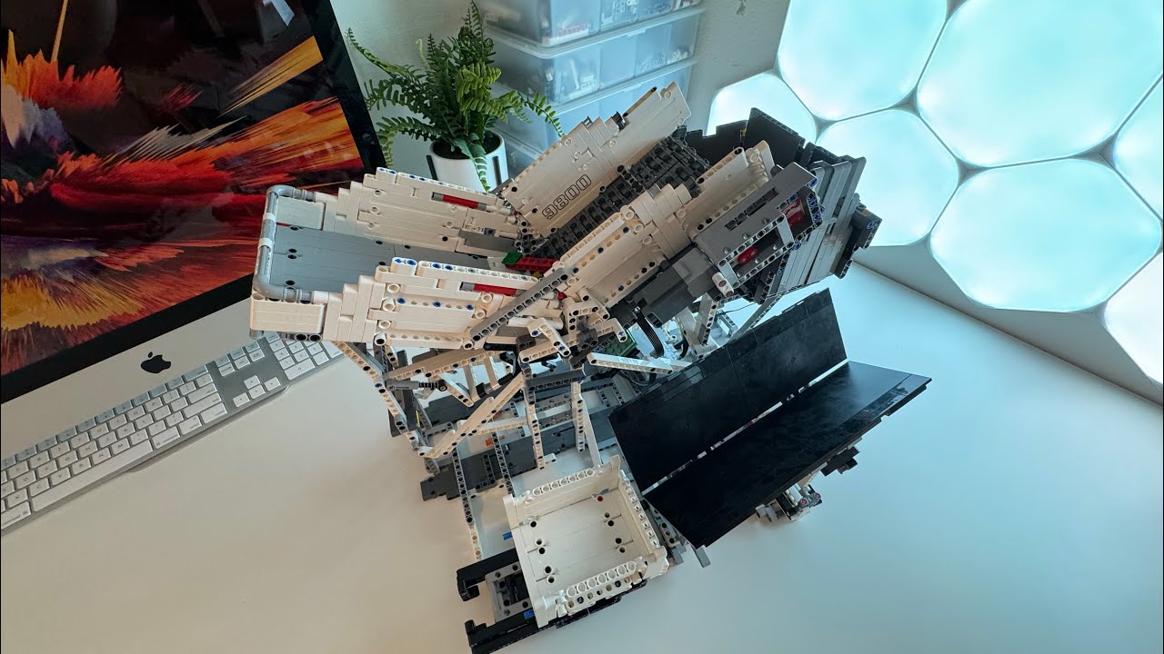
This is the final video in my series trying to make a universal Lego Sorter. This would be a machine that could have any Lego piece dumped into it and the recognize and sort that piece into piles.
VERY HELPFULL Link for people wanting more information on how Lego sorting machines work in case your building your own:
https://br...

Over two years in the making, this is the world's first Universal LEGO Sorting Machine, an AI-powered automated sorting machine that is capable of recognizing and sorting any LEGO part that has ever been produced*.
Follow me on Twitter for more updates and information about this and other projects: https://twitter.com/JustASquid/
Be sure to ...

The rotational slide of the LEGO sorting machine became two dimensional!
🔗 GitHub: https://github.com/BrickSortingMachine
📄 Blog: https://medium.com/@bricksortingmachine
⭐ Credit to projects which inspired this work: https://medium.com/@bricksortingmachine/lego-sorting-machine-overview-d390645759f9
primal shell
clear mantle
ya, I've found a couple. none with instructions
Daniel West has a couple of good writeups (I think on Medium or TowardsDataScience) on how it works, but with an emphasis on the software side. I'm working on a similar project, thinking of using servos to move diverters between chutes.
clear mantle
I like the pan and tilt mechanic of the last one
 lilac pecan
Hello! I’ve been trying to build a component that rotates a spool of tense metal cables back and forth, moving a flexible spine through which the cables are threaded. I’ve been having trouble with the motors I’m using, though. The spool is so tense that two motors are needed to spin it. My program ideally codes for both motors to rotate, stop, then rotate again in the other direction, but only Motor A does this. Motor B rotates fine in one direction, stops only when Motor A begins moving in the other direction (when it should pause like Motor A before switching directions), and does not move at all in the other direction.
I’m using a 12v battery pack, FunduMoto L298P motor shield, and an Arduino Uno. I haven’t affixed the spool to the motor shafts yet, so it isn’t supposed to rotate with them. I’ll attach my program at the bottom of this message and a video of the malfunction.
I’ve tried switching Motor B’s speed pin and the I3/I4 pins to different digital pin numbers, but nothing changed, other than a few times where Motor A would stop moving at all or the motors would move as they did before (Motor B still refused to rotate one way) but the motor shield also produced a weird beeping sound. I tried changing the order of the speed pin writing commands and interface pin commands, but that didn’t change anything.
Is there any way to fix Motor B and have it respond to the get_off() and move_up() commands? Thank you in advance for your help and time!
#include <MotorDriver.h>
#include <seeed_pwm.h>
/*
- ***(m)Motor B turns initially in move_down, but does not get_off or respond to move_up. Fix pin choice, perhaps? []


*/
int pinI1=8;//define I1 interface
int pinI2=11;//define I2 interface
int speedpinA=9;//enable motor A

int pinI3=7;//define I3 interface (POSSIBLE MOTOR B PROBLEM HERE) MOVED FROM 12 to 6; works? [X same as before]
int pinI4=13;//define I4 interface (POSSIBLE MOTOR B PROBLEM HERE) (13 to 6; works?) [X same as before] [when switching to 4, beeps abnormally and otherwise does same as before]
int speedpinB=10;//enable motor B (DEFINITE MOTOR B PROBLEM POSSIBLY) (10 to 6) works? [X same as before but responds to get_off() and now motor A doesn't work at all]

int move_duration=1500;

void setup() {
  pinMode(pinI1,OUTPUT);
  pinMode(pinI2,OUTPUT);
  pinMode(speedpinA,OUTPUT);
  pinMode(pinI3,OUTPUT);
  pinMode(pinI4,OUTPUT);
  pinMode(speedpinB,OUTPUT);
}
void move_up()//moves RIGHT (motor b problem)
{
     analogWrite(speedpinA,200);
     delay(100);//input a simulation value to set the speed
     analogWrite(speedpinB,200);
     digitalWrite(pinI1,HIGH);
     digitalWrite(pinI2,LOW);
     digitalWrite(pinI3,LOW);
     digitalWrite(pinI4,HIGH);

}
void get_off()//get_off motor for moving before new command
{
     digitalWrite(speedpinA,LOW);
     delay(100);// Unenble the pin, to get_off the motor. this should be done to avid damaging the motor.
     digitalWrite(speedpinB,LOW);
     delay(1000);

}
void move_down()//moves LEFT
{
     analogWrite(speedpinA,200);//input a simulation value to set the speed
     analogWrite(speedpinB,200);
     digitalWrite(pinI4,LOW);//turn DC Motor B move anticlockwise
     digitalWrite(pinI3,HIGH);
     digitalWrite(pinI2,HIGH);//turn DC Motor A move clockwise
     digitalWrite(pinI1,LOW);
}

void move() {
  move_up();
  delay(move_duration);
  get_off();
  move_down();
  delay(move_duration);
  get_off();
}

void loop() {
  move();
}
 native cipher
what is the motor voltage and current?
lilac pecan
The motor's voltage is 12V. I'm not sure of the current but I'll look it up in a moment.
The current is 0.5 amperes. Here's the product (it's the 200rpm version):

Greartisan DC 12V 200RPM Gear Motor High Torque Electric Micro Speed Reduction Geared Motor Centric Output Shaft 37mm Diameter Gearbox
 primal briar
anyone have experience driving steppers from an Arduino IDE sketch (ESP8266 and TMC2208 or 2209)
There
's a plethora of helpful libraries but for my project the 2208's "standstill mode" of BRAKING (where it shorts the motor wires for a zero-power brake mode) is essential. I tinkered around with the serial comms in test lash-ups and I see that it can work, but it can't be set as a default, it must be specified each powerup
so there's a library that does this - TMC2209.h from janelia - but it lacks a lot of features I was using from other libraries.
So - are there any other libraries which let you control this feature? Ones with more otehr features, like gentle acceleration/deceleration
or should I try to use both? Or should I try to send the command separately, at each power up
*(it's hard to find specific info on this which is not in the context of building a 3D printer!)
primal shell
My thinking is to send the command separately (you may be able to leverage the library to do the sending for you somehow)
primal briar
I think I was on the verge of doing that awhile back - I actually wired up a sort of serial snooper to find out how the proprietary TMC2209 configurator worked, before I discovered the library that exposed those features, and I saw the serial commands in binary. Wrote 'em down somewhere even, I think...
I think maybe I'll just treat this as a one-off project, use both libraries in an ugly lump, and not try to publish the results (as it's an update to an earlier project, in theory I'd normally do that, but...)
primal briar
hmm, can't seem to get a TMC2208 to respond to the DIR/STEP wires while it's also hooked up to TX for serial commands... back to the data sheet I guess!
primal briar
I found a TMCstepper.h library with an AccelStepper example sketch (AND direct access to mode bits) but the demo crashes hard right at the object.begin line.
So do I dig in and figure out why, or just go back to the original library and try to implement a smooth accel/decel feature using a timer object and voodoo?
Option 3, "drop the whole dang idea" is starting to have appeal...
primal briar
hey why did my last comment show as dated 3 days ago? I think I accidentally edited something.
primal shell
Crashes hard? Probably incorrect configuration, wild pointer, or out of memory.
primal briar
yeah, I tried a stack trace web page (?) but it didn't tell me much. I'll probably have to create a writeable copy of the .cpp and insert debugging messages or something.
or, dig into AccelStepper and find out how it does what it does. Either way, running a loop that says something like stepper.run often enough while also pinging ArduinoOTA and the MQTT link is probably not going to be tenable without more software magic than I can cram into my aging brain.
it's remarkable but I've been Googling for days and can't confirm or deny whether you ought to be able to use the serial interface and the STEP/DIR pins at the same time. The data sheet only states that serial is activated whenever it senses readable data, and that you can use STEP/DIR with the internal pulse generator, whatever that means.

This suggests it should be easy, like, no special measures, it even mentions passive braking and STEP/DIR control in the same place.
But the way I have my test bed wired up now, I can load a sketch that uses STEP/DIR and it works, or one that uses serial control for motion and it works, but I've been unable to cobble together any program that gets STEP/DIR to work after the chip receives serial data of any kind.
primal shell
I wonder if you have to send it some sort of "I'm done talking to you" message to have it go again
What's the level on the DIAG pin?
Are you using one-way serial or attempting bidirectional?
primal briar
I'm using one-way. I made a 2-way wire with that weird resistor when I was snooping howw the configurator tool worked, but all you need to tell it stuff is 1-way (and it's working, I even confirmed continuity across all motor pins in BRAKING mode)
I finally got a stack trace working and it seems as though it does not like the SoftwareSerial for some reason - the library hasn't been updated in like 5-6 years, a previous version is only for AVR (Arduino) archetecture, so that's probably what's going wrong.
I'm going back to some of the other libraries I used earlier - well, trying to figure out which ones did what, I tend not to make notes when I'm struggling through the underbrush on this kind of thing...
oh the stack trace I'm talking about is re: the TMCstepper library which I thought would handle both kinds of access.
I'm gonna try to make a sketch which moves the motor with just the wires, THEN sends a serial command to turn on braking, THEN tries to move again. That'll show - something...?
primal briar
finally realized that at some point STEP/DIR stopped working at all. I wonder when it happened... anyhow, cutting ahead a few steps -
turns out UART needs to be pulled low if you're using STEP/DIR. I probably read that somewhere. So far, it seems like you need to power-cycle the TMC2208/9 to get it working again once it sees a HIGH - not 100% sure on that yet - but I was using D2 as TX so it's HIGH at boot. Thus, if I power cycle the TMC (well, at least briefly disconnecting the 12V feed) AFTER the test loop with STEP/DIR begins, the motor starts turning.
well now that I have the UART pin on D1, it doesn't seem to matter whether it's low or high, STEP/DIR works.
so back to the serial stuff - UART control still works (with D1 as TX). But... if I even so much as let it do software_serial.setup (not even begin()!) then it stops working again - until you power cycle the TMC2208.
I can even put software_serial.setup at the end of the main loop, wiht TX pin driven low in Setup(), and I get one rotation then nothing. So - that SEEMS to imply that just doing anything with the serial pin disables STEP/DIR??
can confirm that the D1 pin (which I'm using as TX) still responds to digitalWrite high/low commands after the first loop of the sketch. So, just doing the .setup() on SoftwareSerial does - something? - which causes the TMS2208 to stop listenint to STEP/DIR, until I briefly remove the 12V power.
I'm baffled.
time for a break. Gonna go find a hammer and see how resilient my skull is.
primal briar
going OK with TMC2209.h - I'll need to figure out how to increment/decrement the speed to approximate accel/decel, which by itself is not a problem, but the system has to handle manual input from a switch as well as MQTT signals (and an end-stop sensor) so the possible number of states it can be in at any one point is somewhat large so I'll need - more short-term memory than I usually have on-hand...
primal shell
Hmm, I'm thinking a shadow table and maybe a state machine
primal briar
I remember learning what a state machine is! 35 years ago. Don't think I've heard of a shadow table.
I have been going through old projects and relearning how I've handled heterogenous commands before - debouncing interrupts, global boolean flags, etc. It's not working very well yet but hey, at least I'm off the merry-go-round of trying half a dozen different stepper drivers at once!
primal shell
For "shadow table", I mean keeping an in-memory version of the current settings, updating it as needed, then copying it to the chip.
Yeah, you were well and truly weary of that merry-go-round 🎠
primal briar
an old standup comic buddy of mine used to have a joke about driving drunk - in a nutshell his strategy was to rub up against the highway guard rails and just drive by feel.
It's very reminiscent of my programming style - change something, dump it to the chip, see if it works, try again... it's slow and inefficient, but not as slow as actually thinking, these days! Ah well, it's a hobby.
primal shell
I'm doing a project at work that way, due to the customer's environment not supporting anything like modern debugging.
primal briar
ARRGH - so it turns out that STEP/DIR works fine after using a serial command after all. I was looking over the Issues page on the Github for the TMC2209.h driver and saw someone asking a similar question, and I explained what I found. The author (hereafter referred to as "BIG JERK") asked for details on how I tested this, as it "should" work... so I reloaded my test sketch, and sure enough, works fine.
I of course blame him.
(and yes, I specifically said at the end of my first response, "if I'm wrong, at this point please just don't tell me"...)
primal briar
well my test sketch is incredibly brittle, almost anything breaks it, so really I'm no further along. In fact, the new weirdie is that neither mode works unless I briefly disconnect the 12V input from the TMC2208! Not even sure what that "resets", it's still getting 5V from the ESP8266. No motor movement after a reset of the MCU, until I pull the 12V wire and plug it back in.
weirdly, I'm just noticing that the EN pin is connected to 12V ground (!) but simply disconnecting and reconnecing that alone doesn't seem to reset anything. I've commented out everything I can from the test sketch, just set up the software_serial and then command the movement (moveAtVelocity) to remove externalities.
primal shell
Wait, is your 5V ground separate from your 12V ground?
primal briar
technically yes, but I've had it powered from the same source in the past. (just can't get troubleshooting data over USB that way). In fact it seems to work OK when I power the ESP8266 from the 12v-5v buck converter AND the USB port at the same time, surprisingly...
the 12V wall wart and the desktop PC are powered from the same wall outlet, although I don't think that actually matters
in the installed version of the project I power the stepper (and TMC) from a 12V wall wart that's also hooked up to a buck converter to power the ESP.
given that it's acting as a MOSFET sort of switch I didn't think it should matter much whether the two voltage feeds had anything to do with one another, and the fact that nothing blows up when I connect USB to the ESP8266 while it's also being powered by the buck converter seemed to underline that.
I suppose I could rely on MQTT for troubleshooting messages and ArduinoOTA for software updates. Proabably ought to.
(I have both features included and working with the main project software, just not on the test sketch)
 astral kelp
primal shell
Wait, is your 5V ground separate from your 12V ground?
astral kelp
primal shell
Wait, is your 5V ground separate from your 12V ground?
I had the exact same issue for this reason when using a TMC2300 carrier board that was simply wired with dupont cables
astral kelp
primal briar
technically yes, but I've had it powered from the same source in the past. (jus...
If theres no diode between the 5V sources you're most likely just backfeeding your usb port instead of actually powering the ESP from both sources
primal shell
I'd have to look up the details, but in many cases, the chip uses the same zero volt reference for both the logic and motor power supplies, so if they aren't connected, one signal or another will "float", confusing the chip.
 pine bramble
primal shell
I'd have to look up the details, but in many cases, the chip uses the same zero ...
pine bramble
primal shell
I'd have to look up the details, but in many cases, the chip uses the same zero ...
And in cases like this I don’t see a downside of having a common ground reference, especially when there’s a measurement against that ground.
primal briar
no argument that the power situation should be less goofy. I guess if I really want to keep proceeding toward my primary goal I should sort out my test setup - things like this have bitten me on the rump more than once before.
primal briar
Well FWIW I'm back to almost-square-one - have a working demo sketch that demonstrably shows UART movement and STEP/DIR movement. Still can't get AccelStepper working though, which is odd...
primal briar
OK I finally have a sketch that does a UART command, bit-bangs STEP/DIR, and moves via AccelStepper, each loop. Now to integrate what I've learned back to my main project somehow...?
primal shell
Progress!
 rancid flint
anybody know where i could buy a cheap timing belt? i want to put together a timing belt with a stepper motor to control a cart for cartpole
 vagrant thunder
rancid flint
anybody know where i could buy a cheap timing belt? i want to put together a tim...
vagrant thunder
rancid flint
anybody know where i could buy a cheap timing belt? i want to put together a tim...
How cheap? You can find all sorts of GT2 timing belts on Amazon or aliexpress if quality is not a concern.
rancid flint
vagrant thunder
How cheap? You can find all sorts of GT2 timing belts on Amazon or aliexpress if...
i would like something with good quality, but i'm new to buying parts. what's a reasonable price to spend? i just wasn't sure where to look
primal shell
Normally "cheap" and "good quality" are in tension
vagrant thunder
Reasonable is relative to your goals and your budget. You can get a pretty nice belt for pretty cheap, thanks to the mainstream popularity of 3D printers. However, you ultimately have to decide based on 1) how much stress your belt needs to withstand, and 2) how much you are comfortable spending on belts.
rancid flint
I was hoping to build something similar to this: https://www.youtube.com/watch?v=rvKnKtFgE7U
I don't have a real budget for the belts, I'm just not familiar with how much I could expect to spend on some. maybe my first question is better framed that way

GitHub: https://github.com/robotics-laboratory/cart_pole
Hardware:
- Controller ESP32
- stepper motor + belt drive
- magnetic encoder
Software:
- Optimal trajectory, acceleration control
- LQR trajectory tracker
- LQR balance regulator
vagrant thunder
We're probably talking anywhere between 1-5USD/ft of GT2 timing belt. If you only need a small loop, buying an exact sized closed loop might be more per foot, but if you're buying a roll I'd expect somewhere around $2.50 a foot?
 inland bear
I know you lot love a good robotics project. Just saw this (a rover project) and had a lovely discussion over in the Pimoroni discord share-your-project channel: <#1271071433010712669 message>
vagrant thunder
Ooo, gotta find Pimoroni's discord invite.
inland bear
Pimoroni discord is linked here (wont let me post invite link): https://shop.pimoroni.com/pages/contact-us
pine bramble
Thought this might be of interest to fellow robot builders. I just posted a first iteration of my RP2040 I2C Slave repository:
https://github.com/ifurusato/rp2040-i2c-slave
This connects a Raspberry Pi master to an Adafruit ItsyBitsy RP2040 slave over I2C, providing the ability to send a one-way message to the slave from the master, returning a single status byte. The next phase of this project will be to convert both the master.py on the Pi and the main.py on the slave to Python classes, so they could be more easily extended and used as base classes.
The only tie with the ItsyBitsy is the use of its NeoPixel for a status indicator. This could be easily modified to use any RP2040 board, and there is an alternate MicroPython file provided for that purpose.

GitHub
A simple I2C slave implementation for the RP2040. Contribute to ifurusato/rp2040-i2c-slave development by creating an account on GitHub.
inland bear
pine bramble
Thought this might be of interest to fellow robot builders. I just posted a firs...
have you seen u2if https://github.com/adafruit/u2if - Not I2c, usb instead, but you get full daughterboard control

GitHub
USB to interfaces implementing MicroPython "machine" module functionalities on a computer. - adafruit/u2if
pine bramble
inland bear
have you seen u2if https://github.com/adafruit/u2if - Not I2c, usb instead, but ...
No, I hadn't before, thanks very much!
inland bear
You remind me of firmata, the arduino sketch that offered similar functionality over Uart, and you picked the firmware functionality to include if advanced desires. There must be a micropython or circuitpython equivalent
pine bramble
inland bear
You remind me of firmata, the arduino sketch that offered similar functionality ...
I wish there was an equivalent but I'm not aware of any.
I'm kinda at a limit already on USB devices, even with an additional Zero4U USB hub installed. And of course USB requires lots of cables and sometimes USB-to-UART dongles, etc., which all take up quite a bit of room, hence my preference for I2C. But the link to the u2if repo is most welcome, looks quite interesting.
inland bear
Ah, now there may be a solution there, adafruit just dropped a few usb hub pcbs with no connectors, so less space
 olive light
at the moment, uart is really the simplest way of doing two-way comms in CP, some ports also have slave SPI, but I2C definitely sounds useful
pine bramble
If I can figure out how to send longer return messages (more than a byte) with my code I will have most of the functionality I need for coms between a Pi and an RP2040 using MicroPython. A shame it's not likely to happen soon for the ESP32 (the MP devs aren't seemingly in a hurry to provide I2C slave functionality, seven years and ticking...).
pine bramble
olive light
at the moment, uart is really the simplest way of doing two-way comms in CP, som...
Yes, but when each UART requires a couple of pins and a Raspberry Pi has only a few UARTs, even with dongles things get out of hand pretty quickly. I've got over 15 I2C devices on the robot, and am already committing seven USB ports.
pine bramble
olive light
actually https://docs.circuitpython.org/en/latest/shared-bindings/i2ctarget/inde...
But not MicroPython, unfortunately. All of my implementations are in CPython and MicroPython.
inland bear
looks like micropython might include a tool for doing firmata like stuff https://forum.micropython.org/viewtopic.php?f=2&t=12252&sid=18396323013fcb943fedc44c33f16132&start=10#p68712
Note that MicroPython includes a tool "pyboard.py" that uses pyserial to do exactly this and you can also use it as a library to send commands to a connected MicroPython board.
olive light
pine bramble
Yes, but when each UART requires a couple of pins and a Raspberry Pi has only a ...
you can do half-duplex uart?
like the dynamixel servos
pine bramble
inland bear
> Note that MicroPython includes a tool "pyboard.py" that uses pyserial to do ex...
Again, I'm already at a limit on both USB and GPIO pins for UART-based coms. It really needs to be I2C at this point.
olive light
and you can bit-bang it too, if it doesn't have to be fast
i2c uses a pair of pins too
pine bramble
olive light
you can do half-duplex uart?
Yes, one of the members on Personal Robotics has been using a Dynamixel protocol to do coms over a six legged robot, using a single dongle to bridge the UART with all the servos. I've encouraged him to distribute his project over github.
pine bramble
olive light
i2c uses a pair of pins too
Yes, but of course you can have hundreds of devices connected to those two pins. I2C is a bus, UART is not.
olive light
pine bramble
Yes, one of the members on Personal Robotics has been using a Dynamixel protocol...
the lizard robot?
pine bramble
olive light
the lizard robot?

GitHub
Code repository for Roz, my quad walker robot. Contribute to JonHylands/roz development by creating an account on GitHub.
Sorry, four legs not six.
I think Jon has agreed to put out a repo for his Dynamixel implementation.
pine bramble
Yes, both Jon and I are using STM32s. He pointed me at the WeAct Pyboards available on AliExpress, which are great, low-cost Pyboard clones (noting that the Pyboard is open hardware). I'll be building a 3 board cluster of Pyboards to control my motors and servos when I get to the next phase of my project, adding another pair of wheels so it'll have six.
olive light
I had some success with CircuitPython and smart servos too, but I used two pins of the UART and some resistors to turn it into half duplex: https://deshipu.art/projects/project-190377/log-217238/
the code is at https://deshipu.art/projects/project-190377/log-217800/
inland bear
here's that usb hub if you end up needing a small wirable form: https://www.adafruit.com/product/5997

Sometimes you've got something with USB host, like a embedded linux board, and you want to connect more than one thing. Or maybe you want to turn something like a keyboard into a ...
pine bramble
Thanks, I'm already using a Zero4U hub (which is the size of a Pi Zero and already on the robot) and have been thinking about that new Adafruit board, as I could replace use of actual USB cables with wires. I don't know if that alters performance or reliability but it certainly would reduce the bulk of cabling.
I'll likely be using UARTs to communicate with the three Pyboards, using USB-to-UART dongles. And all of my MCUs are connected to the Pi via USB so I can rshell into them remotely. With that and a remote keyboard USB dongle, that's why I'm kinda at a max for any further UARTs on this robot and am preferencing I2C for everything else.
inland bear
shielded 4wire cabling for long or noisy runs will probably be sensible if performance or reliability matters. you can get reels pretty cheap
olive light
the nice thing with the dynamixel protocol is that it's also a bus, like i2c, so you can have multiple devices on it
pine bramble
inland bear
shielded 4wire cabling for long or noisy runs will probably be sensible if perfo...
None of the wires will be longer than about 15cm, but there is potential for noise as it's on the robot next to the Pi. I don't really know how much noise that would be in reality.
inland bear
first draft I wouldn't worry, but then again I also got paranoid and bought a reel of shielded (was for some mad usb ideas)
welcome to some meters if you ever in the UK 😁
pine bramble
olive light
the nice thing with the dynamixel protocol is that it's also a bus, like i2c, so...
Yes, Jon has been a big advocate for that, and following a discussion yesterday we'd discussed him packaging up his code with some documentation as a repository, which would make it easier for anyone to understand and use. His brother David has a much larger and more generic repo, and I've been advocating something as simple as possible (80/20 rule), like less than a dozen files if possible.
olive light
you want the data wires to be close together and the same length, the rest is meh at least for low speed usb
pine bramble
olive light
you want the data wires to be close together and the same length, the rest is me...
That's kinda what I thought, thanks. It may be a Mars rover but it's not rocket science... 🙃
pine bramble
inland bear
welcome to some meters if you ever in the UK 😁
Thanks, haven't been in the UK since I left in 2006 (lived there for four years). New Zealand is a long trip...
inland bear
pfff very long, still on the list but my last 16hr flight has left a mark
olive light
I've been burned by i2c on raspberry pi before, it has hardware bugs in the i2c controller
particularly, clock stretching, which you kinda need for bit banging, is broken
pine bramble
inland bear
pfff very long, still on the list but my last 16hr flight has left a mark
Over the past decade I've done six Lufthansa round-the-world trips, leaving from NZ, so I've had waaay too many long flights...
pine bramble
olive light
I've been burned by i2c on raspberry pi before, it has hardware bugs in the i2c ...
Many people I know in the robotics community don't have much success or don't like I2C but I've frankly never had any problems, and my robots typically have between 10-20 I2C devices on board. I typically use Pimoroni Breakout Garden boards as repeaters (e.g., I have one on the back and one on the front of a chicken-sized robot) and keep my wire lengths pretty short. Just not had the problems myself.
Obviously for a large robot one would have to come up with mitigations for I2C or use UARTs or CAN bus.
inland bear
Amplifiers is a good idea. I forgot to say that with U2IF you can also use Blinka to then use circuitpython libraries via the u2if board.
pine bramble
I'm not sure what the right word is, "amplifier" or "repeater", but in any case, something that permits devices to connect at a longer distance from the controller.
There are boards specifically designed for that purpose, I've been using Breakout Garden since I'm already using a lot of those as sensors, etc.
inland bear
yeah repeater, signal conditioner, something like that
or capacitance problem as some might say 😁 (every extra thing on bus)
pine bramble
...and some devices are really noisy. I've got an OLED display and a VL53L5CX and had to put them on IC2 bus 0 to keep them away from the others. I'll probably push the VL53L5CX onto an MCU if I can figure out how to return longer values than a single byte.
inland bear
That 5CX wants a fast separate bus ideally, especially on boot with the firmare sending. Most devices I've seen just offer a known amount of bytes back (you could instead return length of bytes back) and the client keeps reading 1 byte joining them together until finished.
olive light
I suppose a repeater with a buffer could work around a hardware clock stretching bug
pine bramble
inland bear
That 5CX wants a fast separate bus ideally, especially on boot with the firmare ...
Yes, the VL53L5CX is quite a beast.
inland bear
I keep reading the docs and seeing "oh yes you can" then the realisation of not saved 🤦♀️
olive light
you are supposed to power them on one by one and set the address as they come on the bus
inland bear
too many enable pins required, no chip selects please
olive light
they really didn't think it well
pine bramble
inland bear
That 5CX wants a fast separate bus ideally, especially on boot with the firmare ...
I'm a bit like a Jack Russell terrier and just keep digging at stuff until I get it working, but I'll readily admit my own limitations in figuring out how to do that. I'm relying on an existing repo as the real workhorse on the coms, and that repo doesn't support more than a single byte. Getting it to send multiple bytes over the same transaction is what's needed, and I've not quite reached that rabbit yet (to stick with the metaphor).
pine bramble
olive light
I hate how you can't set the address for those distance sensors
That's of course not the fault of the people building the breakout boards, it's endemic to the ST sensor itself. The VL53L1CX and VL53L5CX use the same I2C address. grr.
olive light
yeah
inland bear
muxes for the win
pine bramble
inland bear
muxes for the win
Sure, and there's also I2C address change boards. But that's all more complexity...
olive light
that kinda defeats the whole idea of a bus
inland bear
pain to use but not if designed in
lol, yeah I was debating adding all the alt addresses for all the i2c sensors supported by the WipperSnapper firmware (adafruit IO thing), based on the LTC address changer boards
pine bramble
But... if anyone wants to jump in and work on adding the ability to return more than a single byte, they'd be most welcome. The idea was to provide a general, easy to use I2C slave functionality for the RP2040. As I've noted in the README, the next step is to turn both sides of the communications into classes so they can be easily extended.
inland bear
its a good look, definitely be useful. Also reminded me of the seesaw firmware, where they use a small chip to respond to known i2c commands, and offer gpio pwm i2c uart etc, used on any breakout of component to i2c (rotary encoders etc).
they nicely support changing address etc and if a similar code was done in micro/circuitpython then it could use the same client library
olive light
I've seen some pio based i2c implementations for the rp2040, I wonder how hard they would be to use with MP
pine bramble
inland bear
its a good look, definitely be useful. Also reminded me of the seesaw firmware, ...
I know over the past few years on various forums I've expressed the same thing: surprise that someone hasn't already done this before. I'm really not the best person to do this kind of thing. On Personal Robotics we had a really great programmer create an RP2040 i2cperipheral project in MicroPython (which is probably what @olive light is thinking of), but he sadly left our server and stopped working on the project in 2023, so it's now out of date. I don't know how hard it would be to fork and update that project, it's a bit out of my skill set to do it.
Speaking of: https://github.com/adamgreen/i2cperipheral

GitHub
i2cperipheral - MicroPython I2C Peripheral Library for the RP2040 - adamgreen/i2cperipheral
That is specifically using the PIO if memory serves. It's written in C but builds MicroPython (*.mpy).
olive light
that's what I hate in MP — you have to run as fast as you can just to stay in place when you have any 3rd party code
and it's very hard to get anything merged in the main repo to make sure it won't break
inland bear
so one forks updated the version of micropython https://github.com/adamgreen/i2cperipheral/network
maybe it'll still work if the submodule was updated again.
Circuitpython does break too, but usually code still works untouched, and unless it's a very good reason they'll often maintain both ways for many versions (backwards compatible)
pine bramble
olive light
that's what I hate in MP — you have to run as fast as you can just to stay in pl...
It's both a boon and a bane in any open source community. We all rely on either large corporations providing their employees' projects, or single people generously donating their time. I don't complain about it, knowing that the entire open source community is based on such generosity.
olive light
pine bramble
It's both a boon and a bane in any open source community. We all rely on either ...
I'm not complaining but I feel like it could be improved somewhat
pine bramble
inland bear
so one forks updated the version of micropython https://github.com/adamgreen/i2c...
I don't doubt it would still work. I tried using it with the latest MP build and it failed simply because of the version mismatch. So it might be simply a matter of doing a new build.
olive light
I left when they broke all my sensor drivers that I wrote over several years with a stupid cosmetic change
inland bear
my first real experience of micropython was converting some code that didn't work becuase all the modules had changed prefix, amongst other treasures
I just want to glue stuff together and it work, so I can be done or move onto the next step (in software)
pine bramble
olive light
I'm not complaining but I feel like it could be improved somewhat
I'm not sure how. People have their own lives and their own priorities. If some dork like Musk donated a billion dollars to fund open source software rather than 44 billion for a toy, the whole world would benefit. When I was working for a large IT corporation I could justify and spend time on open source proejcts, as can anyone who can tie a project to their work. Relying on individuals will always have this problem.
olive light
pine bramble
I'm not sure how. People have their own lives and their own priorities. If some ...
I doubt money really help here
respecting other people's work a bit more could go a long way
pine bramble
olive light
I left when they broke all my sensor drivers that I wrote over several years wit...
I'm as tired as anyone of boy programmers making changes for change sake, or to "improve" something that frankly doesn't need improving. I am as tired as anyone of being forced to "upgrade" perfectly functional software all the time. Like: just leave me alone for chrissakes.
olive light
yup
inland bear
can one have multiple things on a uart bus if they all only respond when a command starts with their id prefix? They all listen, and there's only one controller/host
pine bramble
olive light
respecting other people's work a bit more could go a long way
That's the boy programmers needing to improve upon your work by making it better according to their metric of "better", rather than respecting all the hard work that went into the original and the amount of time and effort their constant changes cost everyone. But don't get me started </rant> 😆
olive light
inland bear
can one have multiple things on a uart bus if they all only respond when a comma...
that's how dynamixels work
inland bear
yeah so in theory firmata would similarly work just need to add a prefix element to the codebase
olive light
you need a bit more in you protocol to do it correctly, though
like you need to know when the other side is finished
olive light
you could also do open drain like i2c and do collision detection...
but it gets complicated quickly
inland bear
it's interesting to consider 🙂 i'm more likely to chuck the seesaw arduino code through chatgpt and convert to circuitpython, clean it up after of course
pine bramble
But anything that affects the entire bus affects all the existing devices on that bus, which is why things like clock stretching are so hazardous. The UART-as-bus approaches avoid this by using separate UARTs as sandboxes. A lot of MCUs have a lot of UARTs (like 12 on the STM32) so there's a huge space for hardware extension, which is why the STM32 was designed that way (i.e., for industrial uses).
inland bear
yeah more the merrier (buses and pins).
olive light
nothing like a device stuck in incosistent state on your bus
you can lose all your hair trying to debug it
pine bramble
Update: I've just updated the RP2040 I2C Slave repository by converting the code to an I2CSlave base class, decoupling the ItsyBitsy RP2040 so the base class can now be used with any RP2040. There's now an I2CDriver class with a callback to set the NeoPixel (or perform other functions). So if anyone wants to try it out with a generic Raspberry Pi Pico or other RP2040 board it should (in theory) work. I've not yet tested it on a Pico.
pine bramble
A Further Update: I've added a Sensor class that extends I2CSlave, as an example of how anyone can use the base class. The Sensor class reads a single GPIO pin (I'm using a Sharp IR sensor) and supplies the value of that as an enumerated response to an I2C request.
https://github.com/ifurusato/rp2040-i2c-slave
…and that's it for now, the project does what I need it to do. The current implementation can send up to 32 ASCII characters from master to slave, and only returns a single byte, but that's enough for a lot of things.
pine bramble
Yet Again Another Update: I've added an I2CPicoDriver and a test class for it, to support the Raspberry Pi Pico on SDA pin 16, SCL pin 17, with support for flashing its LED. And tested that this all works on the Pico RP2040. (I don't have an RP2350 so I don't know if that'd work or not.)
inland bear
pine bramble
**Yet Again Another Update**: I've added an I2CPicoDriver and a test class for i...
Should be identical on the rp2040 and rp2350 for i2c and LED flashing.
pine bramble
inland bear
Should be identical on the rp2040 and rp2350 for i2c and LED flashing.
Yeah. I have a base class called I2CSlave that doesn't have any implementation details like NeoPixels, etc. and should work with any RP2040. I've subclassed that as I2CDriver for the ItsyBitsy RP2040 (probably should rename that now to I2CItsyBitsyDriver) and I2CPicoDriver for the Pico. Those subclasses add support for the NeoPixel and single green LED of the Pico resp.
I'd expect the RP2350 should be hardware compatible at the level of registers.
inland bear
Ahhh I seee, sounds good. Thought I saw some recent circuitpython minor changes at neopixel level, but not at the python layer, more the board support package (C).
(maybe it used PIO in circuitpython for neopixels, and that needed tweaking for rp2350)
pine bramble
If you're talking about my code, it's just using registers. No PIO, nothing fancy.
 little needle
Hi! anyone have suggestions for why my drv8825 + 17hs4023 stepper motor makes a ton of vibrations as it turns?
cursive terrace
each "step" is technically a discrete start/stop of the rotor (and windings/magnets), so there's always angular momentum involved -- i haven't worked a lot with those types of chips, but if you drive it in "1/32-Step" mode, each "step" will be a lot smaller overall and you'll get less vibration
 random sphinx
I am looking to use break beam sensors (https://www.adafruit.com/product/2167) to determine if the leg of my robot has reached the end of its swings. To avoid stress on the wires, I was thinking to mount both the transmitter and receiver to the frame of the robot and put a mirror or something like that on the leg of the robot. Transmitter points towards the mirror so it reflects down to the receiver.
Does this IR break beam reflect like that?
With the transmitter and receiver basically next to each other on the frame, so I risk blead over directly from the transmitter to the receiver? In other words, do I need to put something between the two to normally have the beam broken or do it basically travel straight out from the receiver?
I was looking at mounting the transmitter and receiver roughly 1.75" from the centerpoint of the shaft, with the leg of the robot moving 45 degrees up to 4 times per second (forward, backwards, forwards and back again all in 1 second). The specs say these have a 2ms response time, so I am thinking the can respond fast enough to catch as the leg passes across the sensor.
So the 45 degree arc would be 1.375" long. I am planning on putting sensors and the front of the arc, back of the arc and the mid point of the arc.
The motor controllers I am using are supposed to act in "servo" mode, but I cannot get that working, so I figured I could use these break beam sensors as limit switches instead.

Infrared (IR) break-beam sensors are a simple way to detect motion. They work by having an emitter side that sends out a beam of human-invisible IR light, then a receiver across the way ...
cursive terrace
just thinking about the light waves, you could put the emitter slightly behind the receiver, thus making the receiver itself block any possible bleed-over (just guessing)
pine bramble
random sphinx
I am looking to use break beam sensors (https://www.adafruit.com/product/2167) t...
To me this sounds like it would be difficult to accomplish with break beam sensors. I’d probably go with a Hall Effect sensor and a tiny neodymium magnet. Or possibly even a Pololu IR digital proximity sensor. But even better would be to mount a gyroscope on the leg to measure the angle.
cursive terrace
or an actual switch like https://www.adafruit.com/product/819

Micro-switches are often found in arcade buttons and joysticks but they're also really handy in any kind of mechatronics project or when you need a basic sensor. They are always ...
pine bramble
cursive terrace
or an actual switch like https://www.adafruit.com/product/819
Yes, and you can get specialty lever switches with a tiny wire lever or solder a bit of piano wire to them to gain the same effect.
Always use the simplest sensor you can for a given application
Lever switches come in hundreds of different lever shapes and sizes
pine bramble
random sphinx
I am looking to use break beam sensors (https://www.adafruit.com/product/2167) t...
As @cursive terrace noted, a lever switch is probably the most common method. Indeed, they are often called “limit switches”.
The only downside is that on a moving object like a leg, vibrations or jolting movements can cause them to self trigger. For this reason you need to choose the specific model fairly carefully. They’re spec’d with the amount of force required to move them, some are very sensitive some not so much. This is one reason I like Hall effect sensors.
random sphinx
That Adafruit LSM6DSOX 6 DoF Accelerometer and Gyroscope - STEMMA QT / Qwiic (Product ID: 4438) looks much better. I had not even thought of something like that. This gives me the ability to know the angle forward/backward, as well as up/down all in one sensor. Thanks!
pine bramble
random sphinx
That Adafruit LSM6DSOX 6 DoF Accelerometer and Gyroscope - STEMMA QT / Qwiic (Pr...
It’s how your phone knows its position in space.
cursive terrace
oh, yeah, those are lots of fun
pine bramble
random sphinx
That Adafruit LSM6DSOX 6 DoF Accelerometer and Gyroscope - STEMMA QT / Qwiic (Pr...
Most of these 6 and 9 DoF IMUs are connected via I2C, and while some have a facility to alter the address to another (the Adafruit LSM6DSOX can be changed from 0x6A to 0x6B via a solder jumper on the back), if your robot has four or six or eight legs that's not going to work. This problem also arises with any other I2C device where you're using more than the number that can be handled by those solder jumpers, i.e., it's not uncommon.
If you're trying to connect multiple I2C devices that all have the same I2C address you can either use a multiplexer or an address translator:
- An I2C multiplexer like the TCA9548A has the advantage of allowing a larger number of devices at the expense of the delay time it takes to select or iterate through the multiplexed devices, requiring a single multiplexer for, e.g., eight devices. You also then need to provide code (and likely three GPIO pins for A0-A2) to determine which device is actually being polled.
- An I2C address translator like the LTC4316 has the advantage of not requiring multiplexing, but requires one translator per translated device. But they're small and not that expensive.
While I was looking up info on the LTC4316 I found another device you might find valuable: the LTC4311 Extender / Active Terminator. I typically keep my I2C wires under 30cm (ideally, under 20cm) on my robots and have never had any problems. But once you get past about 30cm, and certainly at the lengths from the SBC/MCU that would be required for a robotic leg, you start to run into I2C reliability problems. For that, there's the LTC4311 Extender, which (as per the claims on the Adafruit product page, I've myself never tried this), I2C wires can be up to 3m long. [If anyone is building a robot with legs longer than 3 meters I think there'd be other issues involved...]
https://www.adafruit.com/product/4756

I2C stands for Inter-Integrated-Circuit communications, it's meant for short distances on a PCB or subassembly. But, hey, we're engineers, and we like to push the limits of ...
cursive terrace
i've got one of those on an extended wire of 50 cm
pine bramble
cursive terrace
i've got one of those on an extended wire of 50 cm
Understood, and I think I2C claims 1 meter, but pretty much everyone at the Dallas Personal Robotics Group seems to dislike I2C for being unreliable, and I've not had any problems simply by not pushing the limits so far. If you've not had any problems at 50cm, good on you.
I've just been down in the basement building a new wooden mast for my robot for a Pesky Products MPU9250 IMU I received in the post today, with a 1° accuracy I'm rather excited! ...though just as I managed to get the robot-movement for calibration of the ICM20948 functional... I think the magnetometer calibration for the MPU9250 is similar, i.e., rotate horizontally through 360°, so maybe no effort wasted.
 turbid trail
@pine bramble would like to extend to you all an invitation to join this server:
Personal Robotics is a community server devoted to anyone interested in designing, building and/or programming their own robot. Discussions include hardware and software, sensors, electronics, single board computers and microcontrollers, software design, behaviour-based systems, artificial intelligence, machine learning and more. Here's an invitation link: https://discord.gg/rAZ8px5zud
(I am the one posting this because we block server invitations as a spam prevention measure, but will post them on request.)
 sly sand
For fast bldc controllers is there only odrive? It's expensive.
Encoders do cost as much as the motors.
olive light
if I remember correctly, odrive was created because the other available solutions were too expensive...
primal shell
It depends on what you're doing. Ordinary ESCs can serve in some instances. Some controllers need encoders, some don't. There are some nice mid-price controllers aimed at the ebike market. Back when Allied Electronics was still around, they offered a really nice BLDC motor with built-in controller pretty cost effectively. I'm kicking myself for only buying one.
These BLDC controllers (intended for ebikes) do a dandy job on my electric tractor (2 fast ones for the blades, 2 slow ones for the drive wheels)
 sly sand
primal shell
It depends on what you're doing. Ordinary ESCs can serve in some instances. So...
sly sand
primal shell
It depends on what you're doing. Ordinary ESCs can serve in some instances. So...
I need pretty much a really fast and silent stepper...
Funny enough as much odrive was created to cut down on cost, now they're even more expensive...
primal shell
Hmmm. How fast? Does it need to be a stepper (as in you need precise speed or angles)?
sly sand
primal shell
Hmmm. How fast? Does it need to be a stepper (as in you need precise speed or ...
As fast as the buck permits
Just something that lets me know the position, as it will be mounted in a xy axis machine
ALTHOUGH I don't want to lose more hair that I am already losing for trying to make the thing work
primal shell
I don't have a clear idea of what you're trying to do, but if you just need to know the position, there are add-on position feedback mechanisms that are not expensive.
sly sand
Like?
Lasers/optics may be a thing, but I'd like it to work without much my intervention about making it work with extra sensors...
I don't have that much time anymore unlikely...
@primal shell
pine bramble
sly sand
Like?
Lasers/optics may be a thing, but I'd like it to work without much my inte...
Well, if you don't have much time to accomplish this it's unlikely that you'd have enough time to implement position feedback.
Use of feedback to control for velocity or position is called "closed loop", whereas running a motor with no feedback is called "open loop." A robot can't drive in a straight line without closed loop control (the reason: the left and right motors are running in different directions, and motors' performance is different depending on the direction of rotation).
To add closed loop control to a motor, you add either optical or Hall effect encoders to a rotating shaft. You have a choice: you can control for velocity or position. If they're "quadrature encoders" they have an A and a B channel, which permits detection of direction by checking the phase of the two waveforms. A single channel only permits detection of velocity (essentially a tachometer). In either case you feed your encoder data to a PID controller, which tells the motor controller to either speed up or slow down (in the case of velocity control) or move the shaft clockwise or counter-clockwise (in the case of position control). From this you may correctly surmise that for position control you need quadrature encoders.
Setting up the hardware is neither difficult nor expensive, but either installing an existing PID controller or writing your own and then tuning it isn't easy, even for people who know what they're doing. It's an extremely valuable skill in robotics to master as it's used everywhere, but it does take time to learn how.
sly sand
pine bramble
Well, if you don't have much time to accomplish this it's unlikely that you'd ha...
And that's why you buy a driver to begin with, so you don't have to deal (at least directly), with such thing
From odrive docs I see that they have some self tuning
primal shell
From your discussion of your use case, it doesn't look like you're going for closed loop control, just the ability to push something around and monitor where it is.
pine bramble
primal shell
From your discussion of your use case, it doesn't look like you're going for clo...
I was assuming from the use of a stepper motor rather than a normal DC brushed motor that they wanted positional control. But then thinking about how they wanted it to be "as fast as the buck permits", maybe I was wrong... but there's also: "Just something that lets me know the position, as it will be mounted in a xy axis machine" so I'm confused now. Is there a difference (in hardware) between being able to perform positional control (via feedback) and having access to the position (via feedback)?
Is this a case of being able to monitor where the device (e.g., a robot) is located, or being able to monitor the rotational position of the motor shaft?
primal shell
I figured in an XY axis machine might be some sort of gantry, and maybe a position readout like one for a lathe might do the trick
pine bramble
primal shell
I figured in an XY axis machine might be some sort of gantry, and maybe a positi...
Maybe a clarification from the OP might be in order...
sly sand
pine bramble
Maybe a clarification from the OP might be in order...
Yeah it's a gantry. To be honest I'd hoped that it did exist some kind of open maglev linear motor that worked off shelf, but for so long I haven't seen any. The difference from now and the past, is that now I have some money, but not time :-//
pine bramble
sly sand
Yeah it's a gantry. To be honest I'd hoped that it did exist some kind of open m...
Check out goBILDA for some hardware solutions
 somber berry
Hello! I've decided to get into the world of electronics with cosplay props, and I feel like this one belongs here and I could used some help. I'm trying to make an Assaultron Head Weapon from Fallout 4 (a rifle version with a buttstock) and I'm trying to figure out how I can make the face plates open up. I found a way to get the plates to move up/down with either step motors, servos or linear actuators, but I have 2 issues: 1. How can I get the plates to stay stationary as the arm moves? When the weapon opens up in the game, the face opens up and the plates are pretty much in the same position as they were when stationary. Which brings me to problem 2. Is there a way to make this system pull the plates up/down as well as left/right? I thought about using a servo for the lever and a linear actuator to push the arm holding the plate to the left/right, but I don't know how to achieve something like that when the system is connected by bolts. I'm going to include my sketches so you guys can get a better idea. Hopefully someone could lead me in the right direction! Thanks!


 somber berry
I also feel like robotic arms could help here too. But I know nothing about this stuff...
primal shell
I'll often use gearing systems so things tend to stay where the motor puts them. I suspect you'll need an additional pivoting piece somewhere to enable the dual motion.
somber berry
I agree, so I thought about maybe putting the arm on a slider in the plate and possibly used an additional motor with strings to maybe slide the plate back and forth?
Something like this maybe

I'm probably over complicating it though lmao
 dark saffron
Good Morning! I have an art display (about 2.5 pounds about 1 foot in diameter) which I need to turn from 0 to 180 degrees. I've tried a cheap servo, but it always initializes to a point at power on and nearly wrenches the display off the mount. So I'm looking for a servo or motor ~$50.00 which an Arduino can control that won't move immediately when powered on and will wait for instructions for it to move. Any notions?
pine bramble
dark saffron
Good Morning! I have an art display (about 2.5 pounds about 1 foot in diameter) ...
Most of the servos I've ever seen have a zero position, which at power up will be where they return. The only suggestion I can think of is have that zero position be a good resting position for the display.
dark saffron
pine bramble
Most of the servos I've ever seen have a zero position, which at power up will b...
Yes, that's what I've read too. A friend tried to point to some small RC servos that may not zero on power up, but that had small torque and many had low product ratings. I've seen some DC motors with encoders and hall effect sensors that are cheap enough and look reliable if I can get the torque right.
Any ideas there?
pine bramble
dark saffron
Any ideas there?
Well, Pololu sell N20 motors (“micro metal gear motors”) in a wide array of gear ratios and power ratings, with either extended back shafts or encoders already attached. PID controllers control for either velocity or position; you’d want the latter. All entirely doable.
I wouldn’t necessarily trust off-brand N20 motors. Cheap for a reason IMO.
Note that the really high gear ratios can generate enough torque to tear the gearbox apart. And you’ll want both a fast-blow fuse in-circuit and some kind of current limiting on your motor controller. You really don’t want to stall the motor, even briefly, as it’ll be destroyed.
dark saffron
pine bramble
Well, Pololu sell N20 motors (“micro metal gear motors”) in a wide array of gear...
Thanks! I'll give them a look.
 mortal tide
dark saffron
Good Morning! I have an art display (about 2.5 pounds about 1 foot in diameter) ...
mortal tide
dark saffron
Good Morning! I have an art display (about 2.5 pounds about 1 foot in diameter) ...
Assuming you're using Arduino, the default position when you call servo.attach() is the equivalent of a write(90). If you want it to go to some other position just do an actual servo.write(yourposition) immediately BEFORE the servo.attach() in startup(). Thanks to the Arduino forum for explaining this.
dark saffron
mortal tide
Assuming you're using Arduino, the default position when you call servo.attach()...
Yes, using Arduino UNO. I did read that too! It must depend on the servo. I tried pos = myservo.read() followed by myservo.write(pos) just before the attach(9) for pin 9. It didn't work for me. 🙁
But thanks for the idea anyway!
cursive terrace
the "read" doesn't have any data because the servo doesn't "know" where it is until you set it, which is why you typically set a "start pos" before trying to do anything else with the servo
dark saffron
hmmm, but if the Arduino doesn't know where it is, then it will always jump, right?
cursive terrace
oh, yes indeed -- what you might do (and i have considered this myself) is if you have some non-volatile storage (e.g. disk) is to store the "last known" and then on power up, read that and go from there
the problem is that servos can be manually manipulated or get hung up before they can complete the action, so how do you compensate for that as well?
nope, haven't thought about this a bit....... (yes, i know it's probably a "solved problem" for things like ROS (probably) but where's the fun in that?)
dark saffron
Unfortunately, there is no human to ensure the device hasn't been abruptly turned off or moved while off. There is no good way to ensure the position between power-ups. (sigh).
I got impatient yesterday and ordered parts for this project:

Hackster.io
This instruction will show how to control motor position via Local web network. By engineer2you.
I'll give it a go..
Thanks!
cursive terrace
np
 woeful obsidian
hey im new to robotics can anyone tell me if its possible to have a hat on a raspberry pi while also being able to connect the pins to buttons
this is the hat i want to use if it helps https://learn.adafruit.com/adafruit-rgb-matrix-plus-real-time-clock-hat-for-raspberry-pi

DIY your very own Times Square sign
pine bramble
woeful obsidian
this is the hat i want to use if it helps https://learn.adafruit.com/adafruit-rg...
There are a variety of products that copy the GPIO pins out to another set. Here's a couple:
https://shop.pimoroni.com/products/pico-hat-hacker
https://shop.pimoroni.com/products/mini-black-hat-hack3r
By using male and/or female header pins, soldered on the top or bottom of these boards, you can come up with all sorts of ways of hooking things up. I commonly use the Nano HAT Hacker to give me another set of pins to work with on my robots. The only thing you have to be careful of is that you're not using the same pin for multiple things...

The Black HAT Hacker in bijou form. It's Nano HAT Hacker (formerly known as Pico HAT Hacker)!

Need to detach or debug your HAT? Then the Mini Black HAT Hack3r is for you!
woeful obsidian
pine bramble
There are a variety of products that copy the GPIO pins out to another set. Here...
thank you so much
turbid trail
 split sierra
How do I use I2C port 4 on the Raspberry Pi?
split sierra
How do I use I2C port 4 on the Raspberry Pi?
Re "I2C port 4", why port 4 in particular?
 daring python
split sierra
How do I use I2C port 4 on the Raspberry Pi?
daring python
split sierra
How do I use I2C port 4 on the Raspberry Pi?
What model?
split sierra
turbid trail
Re "I2C port 4", why port 4 in particular?
There's no particular reason for this, just that port 3 is a bit cluttered.
split sierra
daring python
What model?
It's a raspberry pi 4.
pine bramble
split sierra
There's no particular reason for this, just that port 3 is a bit cluttered.
What do you mean by "port" exactly? I've never heard of anything in I2C referred to as ports.
On the Raspberry Pi there are two I2C buses: the "main" I2C bus, described as I2C1 (SDA on GPIO 2, SCL on GPIO 3), and a second, less-used I2C0 (SDA on GPIO 0, SCL on GPIO 1). Each bus can support up to 127 devices, each device having a unique address (usually referred to in hexadecimal, e.g., 0x0F, 0x29, etc. up to 0xFF).
So I don't quite understand what you mean by saying that "port 3 is a bit cluttered".
https://pinout.xyz/
The comprehensive add-on boards & GPIO Pinout guide for the Raspberry Pi
olive light
pine bramble
What do you mean by "port" exactly? I've never heard of anything in I2C referred...
nitpick: the first and last few addresses are reserved, so it's more like a bit over 100 devices in practice
pine bramble
olive light
nitpick: the first and last few addresses are reserved, so it's more like a bit ...
How about I describe it as having an address space of 127 devices then?
olive light
pine bramble
How about I describe it as having an address space of 127 devices then?
what I'm trying to say is that not all the addresses can be used for devices
 thorn rain
Hlo
I'm using esp32 with inmp441 mems microphone, connected to dumbdisplay app, but the issue is that there is too much noise in the audio output.
primal shell
thorn rain
I'm using esp32 with inmp441 mems microphone, connected to dumbdisplay app, but ...
I can think of four likely possibilities: one is mechanically conducted noise, one is electrically conducted noise, one is a decoding issue (like byte swapping that makes small changes seem like large changes), one is a buffering issue (where dropped samples change a smoothly changing waveform into a choppy one)
thorn rain
primal shell
I can think of four likely possibilities: one is mechanically conducted noise, ...
Ty for the advice, I'll try to solve each one u mentioned
 livid pelican
I have a Adafruit Feather nRF52840 Sense which is 3.3v and I want to hook up 4 of the HC-SR04 Ultrasonic Sonar Distance Sensor (5v) with a TXB0104 Bi-Directional Level Shifter in between. I know I could do resistor divider but I have these on hand and want to use them. Just asking if it will work.
turbid trail
livid pelican
I have a Adafruit Feather nRF52840 Sense which is 3.3v and I want to hook up 4 o...
you already have the HC-SR04's? Yes, you could use the level shifter, or just the resistors. The resistors are easy because there's no level-up-shifting needed.
livid pelican
@turbid trail yes I have a bunch of them. Thanks for answering my question!
 rapid flax
Hey all, I'm hoping this is the right spot for this.
I'm thinking about what it would take to make a mini version of the Sisyphus table to have as a desk toy. There are a few diy projects out the to make a full sized one but I'd love to make a tiny one. The first hurdle is the motion system. I'm not really familiar with all the options out there beyond what's used in 3d printing but I know you can't really just get mini linear rails and extrusions. Maybe open up an etch-a-sketch? Any thoughts on a good way to shrink this project down?
TLDR: What's the smallest you can make a 2d motion system within a practical budget?
primal shell
You can make rails out of bent wire. You can use a 3D printed form to shape them against, if you want a particular and/or repeatable curve.
rapid flax
Closing the loop a bit, there are actually several good options and several people who have 'gone before' and documented fairly well. The one I'm looking into is rotor with 'rack and pinion' style. There is some documentation of the early official sisyphus table and that's what they're using and it scales down pretty well. Downside is I'll probably have to write a lot of my own firmware and controlling software but that's half the fun!
pine bramble
rapid flax
Hey all, I'm hoping this is the right spot for this.
I'm thinking about what it...
Have you seen the ServoCity and goBILDA hardware for linear motion? Not cheap but very robust. Or is that still too large?
https://www.gobilda.com/linear-motion-guides
goBILDA is a modern build system designed for engineers, artists, students and makers. It's metric, lightweight, and has an ever-growing library of parts
rapid flax
pine bramble
Have you seen the ServoCity and goBILDA hardware for linear motion? Not cheap bu...
I think these are still a bit bigger than I was envisioning. But that's a nice spot to see different options! I was able to find a linear rail that was only 3mm wide so I may go with that. I'm still napkin papering what exactly I want to use.
vagrant thunder
rapid flax
Hey all, I'm hoping this is the right spot for this.
I'm thinking about what it...
If you have access to a 3d printer, you can prototype a linear rod system with steel rods or even pencils if the lengths are appropriate.
rapid flax
Yep, working on some designs now!
vagrant thunder
If you have access to old pc hardware, a cd drive makes for a great source of parts as well. Plenty of diy CNC machines and 3d printers use them for builds haha
rapid flax
Interesting. I do have an old cd drive actually haha. I've got some 28BYJ-48 motors I was thinking about using but I'll have to crack that drive open and take a look
vagrant thunder
rapid flax
Interesting. I do have an old cd drive actually haha. I've got some 28BYJ-48 mot...
You may need two for a 2d motion system.
rapid flax
Motion system working with 2 28BYJ-48 motors. It executes theta rho coordinates. There seems to be some drift but I still need to root cause
 nimble palm
trying to code this robot with circuit python any good leads?
https://hprobots.com/
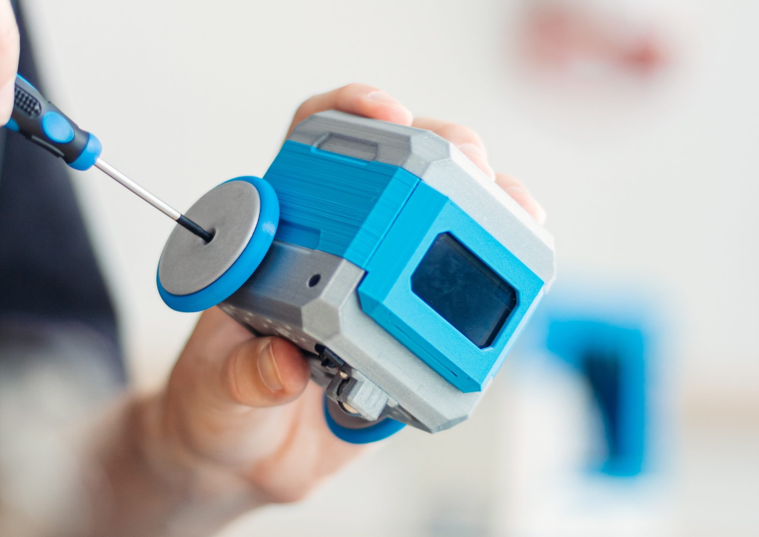
Start with robotics for kids. Enjoy lessons with the STEM+A robot kit revolutionizing classroom or home learning. Foster thinking creatively.
olive light
nimble palm
trying to code this robot with circuit python any good leads?
https://hprobots....
looks like it's just an esp32 with continous rotation servos and some basic sensors
not great for circuitpython, because it has no native usb, but can be used with thonny or web workflow
nimble palm
It has micropython code in the blocks
but I tried to use circuit python and libraries are not compatible
or biceversa there are great libraries in circuit python I want to use but dont work in Thonny IDE
for this robot
olive light
of course circuitpython would not be compatible with their micropython code generator, you'd have to write your own code
you may be able to use some of the circuitpython libraries in micropython with blinka
nimble palm
yeah I am new to python I come from Arduino 😄 it was a bit confusing since both are "Python"
but I love the REPL and simplicity in code
I am wondering if copilot can ocnvert the code and libraries for me
 signal abyss
I can't find an esp32 model on adafruit io that matches what I have, what device do I pick?
 signal abyss
This is what I have btw

ESP-WROOM-32 ESP32 ESP-32S Development Board 2.4GHz Dual-Mode WiFi + Bluetooth Dual Cores Microcontroller Processor Integrated with Antenna RF AMP Filter AP STA Compatible with Arduino IDE (1 PCS)
 ocean oxide
signal abyss
I can't find an esp32 model on adafruit io that matches what I have, what device...
ocean oxide
signal abyss
I can't find an esp32 model on adafruit io that matches what I have, what device...
Are you trying to use Wippersnapper? That is only available for the supported boards in the list.
You can connect to Adafruit IO from Arduino or CircuitPython https://learn.adafruit.com/welcome-to-adafruit-io
signal abyss
ocean oxide
Are you trying to use Wippersnapper? That is only available for the supported bo...
My robotics teacher just told me to "choose a generic one with a similar pinout"
But none of them look similar at all so I'm at a loss
ocean oxide
What is your assignment, what are you supposed to do?
signal abyss
He told me to connect the esp32 to adafruit io and successfully:
- make some change on the esp32's pins affect a value block on a dashboard
- make a toggle on the dashboard turn on the esp32's led
ocean oxide
What programming language are you using?
signal abyss
python
ocean oxide
Ok, so you don't need to choose any board from the site. Choosing a board is only for using Wippersnapper, which generates the firmware for the board without needing to code it. And it only works for the Adafruit boards in the list.
signal abyss
oh alr
ocean oxide
The guide i linked above should help you get started with connecting to Adafruit IO from your code
signal abyss
ocean oxide
You can connect to Adafruit IO from Arduino or CircuitPython https://learn.adaf...
Btw what's circuit python?
pine bramble
signal abyss
Btw what's circuit python?
There are three main flavours of Python:
- Python (sometimes called "CPython" as it's written in C) is the default (reference) implementation of the Python language that runs on everything from Raspberry Pis, laptops, desktops, servers and in the cloud, see https://www.python.org/
- MicroPython, the original subset of Python designed for microcontrollers (the STM32, SAMD, ESP32, RP2040, etc.) see: http://micropython.org
- CircuitPython, an offshoot of MicroPython branded and developed by Adafruit (also for microcontrollers), see https://circuitpython.org/


MicroPython is a lean and efficient
implementation of the Python 3 programming language
that includes a small subset of the Python standard library and is
optimised to run on microcontrollers and in constrained environments.

The easiest way to program microcontrollers
olive light
there is also pypy, jython, stackless python, iron python and a number of other implementations, but they are all for the big computers
pine bramble
olive light
there is also pypy, jython, stackless python, iron python and a number of other ...
I wasn't trying to be exhaustive...
olive light
I know, but it sounded a bit like there are only three, so I wanted to clarify
 muted pike
nimble palm
I am wondering if copilot can ocnvert the code and libraries for me
muted pike
nimble palm
I am wondering if copilot can ocnvert the code and libraries for me
Copilot, and other AI coding tools, can assist in code conversions between languages. They can often produce working code, but providing guidance (actual programmer knowledge) will usually make the result a lot better. Based on the current LLM capabilities.
nimble palm
It helps as a base or to solve specific lines of the code that have errors
vagrant thunder
nimble palm
It helps as a base or to solve specific lines of the code that have errors
I generally recommend against its use for beginners, as it fundamentally reduces the likelihood of learning what the code is doing and the methodology of looking for errors. It’s a great tool to accelerate development after the basis has been formed, but using it too early on can create an unhealthy dependency.
primal shell
It can also lead to a soul-sapping struggle where the LLM suggests something that compiles without errors, but doesn't quite do what was hoped for, and debugging it involves a lot of back and forth, analysis, testing, and learning that exceeds the effort of learning how to do it, causes the user to give up in frustration, or both.
pine bramble
vagrant thunder
I generally recommend against its use for beginners, as it fundamentally reduces...
It also helps to realise that the LLM has absolutely no understanding of the logic of code, no ability to actually execute it, no capacity to recognise beginning or ending state. It's just been trained on enormous amounts of code stolen (without credit or acknowledgement, mind you) from places like github, StackOverflow, and Reddit. It treats code exactly like it treats a novel by Hemingway or Elon Musk's tweets.
And secondly, it helps also to remember that of its training data, a lot of the code available online is not working code, it's often people asking how to fix a problem (with a code example), unfinished or obsolete projects, code in similar but different languages (Python vs. MicroPython, Java 1.4 vs Java 17), etc. LLMs don't differentiate any of this, it all just gets sucked up in the model.
muted pike
How much help or hindrance it is is also depends on your usage style. I know enough not to just 'trust' its output, but by asking for alternatives and comparisons that I then pick from helps. Getting it to list pros and cons help fit to 'my' current scenario, and still show options I may not have considered. Because I know too many programming languages, and am currently 'thinking' in the wrong one.
pine bramble
muted pike
How much help or hindrance it is is also depends on your usage style. I know eno...
I dunno, almost every session seems to end with it apologising for providing me with bad information. It seems to be utterly unable to differentiate between Python and MicroPython in its output, sometimes even within the same session, where I correct it (saying "MicroPython please" after initially telling it that) and five minutes later it's back to Python. Or it's providing code compatible with an ESP32 but not an STM32. Or it mixes up similar libraries, or...
Though I see what you're saying, as it sometimes can provide a more Pythonic example (for this mostly-Java programmer) but that's offset by not being able to remotely trust its output. And this is for quite simple requests. I can't imagine how it would handle a more complicated, object-oriented, multi-class project with any complexity. I'd spend more time debugging its output than writing the code myself.
[And this may be a sidebar, but the fact that all of its ability to do any of this is by using, without acknowledgement, all of the work we as programmers have provided online for decades, under an open source or proprietary license (MIT, BSD, CC0, GNU, Apache, etc.) that has been clearly ignored. OpenAI is profiting from the entire human race's work, and not paying for that work. Their argument is that their technology is simply too world-important to permit a cease and desist order.]
muted pike
Ignoring the political, social, sidebar rant. It is what it is.
I haven't tried with micropython, but I have had some luck with circuitpython by putting the circuitpython guidelines into the custom instructions. It still needs an occasional reminder, but does not 'forget' as often. I have a few different 'context' custom instructions that I switch between.
daring python
pine bramble
There are three main flavours of Python:
* **Python** (sometimes called "CPytho...
oh you're selling python short! There's Cython, Jython, IronPython, RustPython, and I'm sure more besides
pine bramble
muted pike
Ignoring the political, social, sidebar rant. It is what it is.
I haven't tried...
Yes, I'm perfect aware of that. I've already been corrected on the matter once. I chose to say there are three "main flavours" because the rest of them are nowhere near as important to this community as the ones you've listed. Context matters.
daring python
Look, there's only one main flavor of kitkat, but if you're getting weird, let's go all the way! Green tea! Soy sauce! Strawberry! Rum! Cherry Blossom!
pine bramble
daring python
Look, there's only one *main* flavor of kitkat, but if you're getting weird, let...
Do you live in Japan?
daring python
No, that's the best part, the weirdest flavors are unavailable to me! But at least I can run any flavor of Python I want
I used to use ActivePython on SPARC hardware
for when your snake needs a little jolt
pine bramble
daring python
No, that's the best part, the weirdest flavors are unavailable to me! But at lea...
In Japan there are seasonal flavours; limited edition flavours; island, prefecture and city flavours; and meme/themed flavours, as well as others. Sublime Yuzu is especially good.
As I was saying, context matters. When answering a question it is usually not helpful to provide extraneous details that are irrelevant to or may confuse the reader. In this case it was someone who had no prior knowledge of Python, so listing every known flavour seemed very unhelpful to the person. But I can usually expect someone to fill in the blanks, as it seems very common to correct any small, perceived mistakes anyone makes online. Was that necessary?
https://www.japancandystore.com/blogs/okashi/kit-kat-flavors

Japan Candy Store
Welcome to the extraordinary world of Japanese Kit Kats, where the classic wafer and chocolate combo from Nestle is transformed into a whimsical array of flavors. Known for its love of novelty and regional diversity, Japan has given this beloved treat so many different unique, and quirky twists. From traditional tastes
daring python
Of course it wasn't necessary, but it did let me segue into kitkats, so there's that
pine bramble
daring python
Of course it wasn't necessary, but it did let me segue into kitkats, so there's ...
In a couple of weeks I'll be back in Tokyo so I'm keen to see what the latest is... (though I'm much more into mochi than KitKats)
daring python
Bakeable kitkats?!?!

Jurassic Park - Yeah, but your scientists were so preoccupied with whether or not they could, that they didn't stop to think if they should. - Malcolm (Jeff Goldblum) to John Hammond (Richard Attenborough)
More videos at my https://LoveMovieQuotes.com site!
pine bramble
daring python
https://www.youtube.com/watch?v=g3j9muCo4o0
heh, that quote kinds sums up my feelings about a lot of things lately... not just KitKats
olive light
kids these days
 real rivet
hey guys I'm struggling with some things related to some adafruit hardware and raspberry pi - I've got a 3b+, and a TCA9548A - and I'm wanting to communicate with AS5048B on I2C - I see lots of kinda scattered information about it all and managed to get it wired up right, and where I can run 'sudo i2cdetect -y 1' and it'll show me the 70 address of the multiplexer, and the 40 address of the (first) AS sensor - but I'm having trouble figuring out now how to actually use the sensor's information
I do see a github with some details of using the AS5048B with a pi - its written in CPP:

GitHub
AMS AS5048B library to interface the sensor with Raspberry Pi - ansari97/AS5048B_WiringPi
and while that seems promising - the only code I've found that works with the TCA9548A is written in python - and I have gotten as far as selecting the channel the I2C device is on, which seems to work
but uhhh.... definitely get lost now trying to cobble this all together haha - anybody have experience with that sensor or I2C in general and can let me pick your brain?
real rivet
Pastebin
Pastebin.com is the number one paste tool since 2002. Pastebin is a website where you can store text online for a set period of time.
^ here is what I have semi - working, I can get the "ANG1" printed out, but uh, it always says the same value even if I rotate the magnet on the sensor, but if I restart the script it seems to show another value when i've moved the magnet, or even slightly varied values (noisy input) as if its getting correct information from the sensor, but doesn't update when it changes until the script is restarted
real rivet
disregard - I coerced chatGPT in pointing out how I'm trying to read from the zero registers instead of the angle registers >.<
 dire iris
I've never designed my own hardware project, and I have an idea that I would like to implement. I would like to code in (circuit/micro)python, and control two stepper motors and 6 servo motors (and maybe a strip of leds). I'm trying to figure out at least a first set of hardware to start working with. Would something like ESP32 Feather V2 + 2-Stepper featherwing + 8-servo featherwing work? Is there a better way to go? Simplicity to get working is my top priority. (It will be a wall mounted thing, so will I assume use AC wall power, if that matters)
dire iris
Maybe the "Kitronik Robotics Board for Raspberry Pi Pico" would work.
primal shell
You may not need the servo featherwing, as many boards have PWM outputs that can control servos
turbid trail
dire iris
I've never designed my own hardware project, and I have an idea that I would lik...
I would suggest using an ESP32-S3 Feather if you are using CircuitPython, which will expose the CIRCUITPY drive to USB. Your suggested combo sounds like it matches your requirements. https://www.adafruit.com/product/2927
A Feather board without ambition is a Feather board without FeatherWings! This is the DC Motor + Stepper FeatherWing which will let you use 2 x bi-polar stepper motors or 4 x ...
vagrant thunder
dire iris
I've never designed my own hardware project, and I have an idea that I would lik...
For AC wall power, the metro esp32-s3 might be a better base for its dc power jack and side-mounted on/off and reset switches. This does mean you’ll need the shields instead of feather wings, but those counterparts are functionally equivalent.
dire iris
vagrant thunder
For AC wall power, the metro esp32-s3 might be a better base for its dc power ja...
and the shield needs its own (non-jack) power, so that doesn't save that hassle, looks like
vagrant thunder
dire iris
and the shield needs its own (non-jack) power, so that doesn't save that hassle,...
This shield? https://www.adafruit.com/product/1438 You can use the barrel jack to power both the esp32s3 and the motors. The servo shield will need a separate 5v supply regardless.

The original Adafruit Motorshield kit is one of our most beloved, so we decided to make something even better. We have upgraded the shield kit to make the bestest, easiest way to drive DC ...
dire iris
Hard to sort all this out, but it looks like Metro wants 6-12V and the servos want 5-6V, and the heftiest 6V power supply at adafruit is 5A and the heftiest 5V supply is 10A and I may need the 10A so I may need to go with the feather-based solution. But I'm cross referencing product pages and datasheets and tutorials for 6 boards plus various power supplies, cables, and adapters, so I may be wrong.
turbid trail
dire iris
Hard to sort all this out, but it looks like Metro wants 6-12V and the servos wa...
you can power the Metro with 5V at the USB port
dire iris
The board says "6-12V DC" and https://learn.adafruit.com/adafruit-metro-esp32-s3/pinouts says "Provide about 6V-12V here to power the Metro." so you see my confusion.
turbid trail
dire iris
But thanks.
That also says 6-12V
oh, at the USB port. Yes. but the reason to pick Metro over feather was the barrel jack
which I can't use.
I can give a feather 5V at the USB port just as well
dire iris
I'm so confused about powering steppers and matching them to the driver, I'm now trying to figure out how to make my project without them.
vagrant thunder
dire iris
Hard to sort all this out, but it looks like Metro wants 6-12V and the servos wa...
How many and what kind of servos and motors are you using?
dire iris
I think I need two steppers (think X and Y of an XY plotter) and 6 servos (one little grabber probably, and 5 that have to rotate to 0 or 90 degrees) for various other bits of my project. That's all I know.
vagrant thunder
I remember recommending the metro for a 12v supply to power the metro and the stepper motors. The servo shield basically always needs its own power source despite it being 5-6v power.
dire iris
(I am trying to create the equivalent of those 15-puzzle sliding tiles toys... but wall mounted and bigger ... so X-Y-Grabber to move the tiles around and 5 servos to lock in rows so they don't fall down. Maybe 10 servos if I need more power/stability on the row-holding-up levers)
How do I convert wall power to 12V for the metro and 5-6V for the servo shield? Do I need two plugged in power supplies?
I might be better off with something like this https://kitronik.co.uk/products/5329-kitronik-compact-robotics-board-for-raspberry-pi-pico which does 8 servos and 2 steppers on one board.
vagrant thunder
Two supplies is easiest if your setup allows for it. If not, you could use https://www.adafruit.com/product/1385 to step 12v down to 5v.

Your power supply problems just got SOLVED! This little circuit board may look tiny but inside is a high efficiency DC/DC step-down converter which can output up to 3 Amp at 5V without the ...
vagrant thunder
dire iris
I might be better off with something like this https://kitronik.co.uk/products/5...
With this, you’ll need 5v steppers instead of 12v. They exist, but your options become a bit more limited.
dire iris
so I'd need https://www.adafruit.com/product/352 and https://www.adafruit.com/product/1466 for example and just be careful about which barrel jack goes with which.

This is a beefy switching supply, for when you need a lot of power! It can supply 12V DC up to 5 Amps, running from 110V or 220V power (the plug it comes with is for US/Canada/Japan but you ...

Need a lot of 5V power? This switching supply gives a clean regulated 5V output at up to 4 Amps (4000mA). 110 or 240 input, so it works in any country. The plugs are "US 2-prong" ...
$40 just to get wall power in
vagrant thunder
Does your system expect a lot of holding torque? Would using solenoids like https://www.adafruit.com/product/1512 simplify the power and design?

Solenoids are basically electromagnets: they are made of a big coil of copper wire with an armature (a slug of metal) in the middle. When the coil is energized, the slug is pulled into the ...
dire iris
I'm using the servos to hold up a whole row at once (even though only one is being held up, I don't want to use 25 solenoids to hold up one specific tile at a time.) I need to hold up a row at a time. If a solenoid could push forward a full-width (1 ft?) bar I could use those instead of servos.
solenoids don't seem easy to attach things to
vagrant thunder
dire iris
solenoids don't seem easy to attach things to
https://www.adafruit.com/product/413 looks much easier to attach a bar to

Solenoids are basically electromagnets: they are made of a big coil of copper wire with an armature (a slug of metal) in the middle. When the coil is energized, the slug is pulled into the ...
dire iris
Yeah the tutorial using those https://learn.adafruit.com/midi-solenoid-drum-kit/mallet-assembly gives some hope.
They drive like motors? Meaning 2 more motor shields to run 6 of them? or based on this https://learn.adafruit.com/midi-solenoid-drum-kit/circuit-diagram I just need a $4 ULN2803 to drive up to 8 of them?
vagrant thunder
dire iris
They drive like motors? Meaning 2 more motor shields to run 6 of them? or based...
The uln2803 is perfect for this if you have the means of soldering it up. https://www.adafruit.com/product/2077 is nice if you need to stack it all up in one place.
This prototyping shield is the best out there (well, we think so, at least), and now is even better with Version R3 - updated for the most compatibility with just about all the Arduinos! It ...
dire iris
thanks!
 dense isle
anyone know of any sample code for running 2 steppers simultaneously with the motor control featherwing? Specifically how to time it so that the two can run for the same amount of time, but at different speeds. For x-y CNC-type control. Is it possible in CircuitPython? or am I going to have to use Arduino?
vagrant thunder
dense isle
anyone know of any sample code for running 2 steppers simultaneously with the mo...
In arduino, I believe accelStepper has some examples here: https://www.airspayce.com/mikem/arduino/AccelStepper/
I don’t want to say it’s impossible in circuitpython, but the only means I can think of is defining your own function to manually call onestep() on each motor based on how fast you want them to go.
dense isle
vagrant thunder
In arduino, I believe accelStepper has some examples here: https://www.airspayce...
OK thanks. I just really dislike c++ 🙂
I had some success on a different project with using an Rp2040 to talk directly to a trinamic/btt stepper driver, but couldn't do it in CP because the loop timing wasn't tight enough to get a consistent speed.
vagrant thunder
Fair. The ease of a Python-like system is tough to beat, but the performance of not having interpreter overhead is often worth the struggles.
If you’re okay with reading C++ more so than writing it, you could also take to pulling code snippets from 3d printer or CNC firmware sources.
dense isle
On a side note, I'm considering designing a featherwing that will hold 2 of the aforementioned stepper drivers. Just because. Will see how the adafruit board performs... having stealtchop for quiet motors might be worth it.
nimble palm
just sharing, How to make a Santa robot Otto, step by step https://www.hackster.io/527881/hp-robots-santa-otto-c3803e

Hackster.io
3D Printable and Programmable Santa Claus Otto Robot for Children By Camilo Parra Palacio and Alex Glow.
real rivet
I'm struggling a bit with python code on a raspberry pi to spin a BLDC with its ESC connected to a PCA9685. I'm not entirely sure if my problem is my cobbled together code, or if I need to somehow give the ESC some sort of "arming" sequence to get it to spin up. Right now if I power it up with a battery, it'll give me a 3 beep tone that as far as I understand means its working, but I should get more tones after that. A radio transmitter might be sending something along the lines of what I'm trying to do here, but this isn't working for me. Could be the code, the timing of the changes to the arming process, the values could even be wrong for what the ESC expects, which this is a BLHeli_32 firmware ESC if that matters. It doesn't give any compile errors, but when it reaches the part where it should spin up the motor it just does nothing, which is why I think I should be hearing more beeps like when an RC transmitter connects to an ESC.
My hardware setup is rPi3B+ --> TCA9548A --> PCA9685 --> Aikon AK32 single ESC --> motor
My code is:
Pastebin
Pastebin.com is the number one paste tool since 2002. Pastebin is a website where you can store text online for a set period of time.
I'm gonna experiment here later with connecting an LED to the PCA to make sure I'm getting what I expect there, but if anybody has ideas I'm pulling my hair out over here 😄
olive light
real rivet
I'm gonna experiment here later with connecting an LED to the PCA to make sure I...
do you have a microcontroller board at hand so that you could try pwm directly from it? like the rpi pico for example?
real rivet
I have an arduino
uno
Let me dive into getting a test going on there - that should be possible right?
just wiring the ESC black / white pins that would go to the PCA into the arduino with dupont wires?
olive light
yes, arduino has a servo library you can use to generate the pwm signal
the esc basically takes the same signal as a servo
real rivet
I think what might be holding me back is just the arming sequence
like these RC esc would do a "beep beep beep" to tell me it sees the 3S battery, then probably another beep or two when its armed from a transmitter normally
olive light
hobby servos don't have an armin sequence, they just expect 50Hz pwm signal with varying duty cycle
real rivet
right so I think I need to sort of fake that for the ESC and BLDC
olive light
and that's what the rc radio outputs
real rivet
gotcha, I'm having trouble finding clear standards for what that sequence should be really
olive light
do you have a manual for the esc?
real rivet
like maybe theres some universal expected timing / high and low PWM value to give it, or perhaps all RC transmitters are different
its kind of a generic one from aliexpress, this one here:
olive light
no, rc transmitters are very simple, 50Hz pwm signal with duty cycle between 1000 and 2000 us
real rivet
perhaps I'm using the wrong lingo too 😄
I mean like the RC uhh
receiver?? on like a drone
primal shell
The usual arming sequence is going to maximum and then to minimum
real rivet
which the ESC hooks up to
yeah that is what I thought - in the code I sort of tried to do that, but I'm not sure about my timings
or even if the math is right for the PWM signal I'm trying to give the PCA
olive light
try with arduino first, at least you will know the esc works
real rivet
yeah that is a good idea, I'll give that a shot here today if I can wrap my head around it and find some good example code
real rivet
while I have you @primal shell do you know if the arm sequence has to happen immediately on startup of the ESC?
like right after the first 3 beep jingle it needs to quickly send the right max/min timing sequence? Or could it have been powered up for any length of time and when that arming sequence comes it'll still arm?
primal shell
Should be any length of time for most ESCs. Basically they want to know what the minimum and maximum inputs are going to be, so they scan scale to match your setup, and they want to start at minimum.
Mine will just sit around and wait until they get the sequence
real rivet
ok cool because I been worried I need to perfectly time that after startup, so thats a relief haha
well thanks guys I'm gonna go tinker a while and see what I can figure out!
olive light
with rc radios you would get that sequence by manually moving the throttle up and down
so they expect human timing
real rivet
ah good point yeah
should that "ramp up" like a controllers stick being moved up over the course of a half a second or so? Or do you guys think its fine to just immediately jump between min/max values and it'll still accept it?
Sorry for a million questions I just don't know a whole lot about the RC world 😄
primal shell
I'm guessing it's expecting a ramp, but it comes under the "try it and see" umbrella
real rivet
haha fair enough, well this is enough info to send me down a pretty deep rabbit hole so I'll be back if I get stuck
real rivet
Ok running the arduino sweep test makes it sing a funny song on the motor lmao
so it seems to recognize the PWM coming from the arduino then - even if its not arming it properly the ESC "sees" it
makes me think there may be problems with my code, and my somewhat complicated series of connections from the pi to the esc
got it spinning on there, definitely helps clarify where I'm going wrong - thanks for the tips guys!
 humble hollow
Super beginner and basic at coding but joined robotics team and my job right now is to deploy lights on a rover:
need your feedback on my LED implementation for the robotics rover. The electrical team gave me detailed instructions, and here's what I've put together:
Hardware Requirements
Using WS2812 LED strips (30 LEDs)
Each LED draws 60mA at full brightness, so total current draw is 1.8A
Need external 5V power supply since Arduino USB (500mA) isn't enough
Added safety features:
1000 µF, 6.3V capacitor across power lines
Fuse for overcurrent protection
Backfeed protection for Arduino
My Implementation; I coded it (used a bit of feedback and google + AI to learn cuz I am super new sorry); can I get any feedback pls? Just trying to learn

A tool for sharing your source code with the world!
@turbid trail really sorry to ping, but if you have a chance, can you look over this for me?
thanks regardless
turbid trail
humble hollow
<@329766224093249548> really sorry to ping, but if you have a chance, can you lo...
Please don't ping. There are plenty of people to answer your question. This isn't particularly a robotics project, so #help-with-arduino makes more sense. check out the fill() routine, which does what your setColor() routine does, and more.
humble hollow
turbid trail
Please don't ping. There are plenty of people to answer your question. This isn'...
so sorry about that; I'll try to put it there
sorry about pinging i realized chat was inactive and saw you were
really sorry
humble hollow
turbid trail
Please don't ping. There are plenty of people to answer your question. This isn'...
also thanks, should i delete my message here and post it in help with arudino?
turbid trail
humble hollow
also thanks, should i delete my message here and post it in help with arudino?
if you want to ask more about arduino code, ask there. If you have specific robotics q's, could ask here
humble hollow
turbid trail
if you want to ask more about arduino code, ask there. If you have specific robo...
Oh okay, I'll post it in there then 🙂 thanks
 wicked turtle
I know this is a loaded question, so forgive me. I'm making sets of fairy wings to be used in a community play. I've got a good design that works well but the servo models I've tried so far are distractingly loud. Imagine 7 people on stage with a constat whirr, whirr, whirr, whirr as the wings flap. I've tried mg90s and mg996r's but they're just as loud as the cheap sg90s. Anyone have any suggestions? I've tried lithium grease in the gear box. Going to try wd40 today. Wrapping them seems to just make the tone deeper rather than muffling it.
 dense mesa
Just have the performers drink Red Bull. (joking)
olive light
wicked turtle
I know this is a loaded question, so forgive me. I'm making sets of fairy wings ...
There is little you can do if you insist on using the hobby servos. They are all originally designed for remote vehicle control, and noise was never a concern in their design.
dense mesa
wicked turtle
I know this is a loaded question, so forgive me. I'm making sets of fairy wings ...
How big / heavy are the wings?
And how fast are you moving them
wicked turtle
The wings are pretty light, around 30g
olive light
when I made moving cat ears, I worked around the problem by cutting the pwm signal when they weren't moving, which made them shut down the motors, so they are only noisy when they actually move the ears into another position, but that doesn't work in your case
wicked turtle
I've varied the speed to try to make it better. It really just changes the pitch
I'm already doing that. They're not buzzing when still, just when moving.
is there an "above" hobby level servo that is quiet that would fall inthe no more than $50 per servo range?
I'm not against spending a little money to accomplish this. I just don't have experience with more than hobby models.
I don't want to start buying half a dozen $50 plus servos to see which ones are quieter, if I can help it.
olive light
I don't know any, I mostly move below the $5 price range
dense mesa
Do all of those motors use plastic gears? I wonder if metal gears would be quieter. nvm. I missed that you already tried a mg90s
turbid trail
wicked turtle
I don't want to start buying half a dozen $50 plus servos to see which ones are ...
There are multiple discussion of this in the forums, e.g.:
https://forums.adafruit.com/search.php?keywords=quiet+servo&terms=all&author=&sc=1&sf=all&sr=topics&sk=t&sd=d&st=0&ch=300&t=0&submit=Search
https://forums.adafruit.com/search.php?keywords=silent+servo&terms=all&author=&sc=1&sf=all&sr=topics&sk=t&sd=d&st=0&ch=300&t=0&submit=Search
primal shell
wicked turtle
I know this is a loaded question, so forgive me. I'm making sets of fairy wings ...
Gimbal servos are quiet, and you can get good control of them with a FOC board
wicked turtle
turbid trail
There are multiple discussion of this in the forums, e.g.:
<https://forums.adafr...
I looked through a good number of these before posting. Most deal with chatter while sitting still. I will dig through them again to see if I missed something.
wicked turtle
primal shell
Gimbal servos are quiet, and you can get good control of them with a FOC board
I didn't realize "gimbal" servos were different than what I had tested. I will take a look at this as well. I appreciate everyone's feedback.
wicked turtle
This looks promising, If I keep the motion range within its limits, it shouldn't "click". https://www.adafruit.com/product/413
Solenoids are basically electromagnets: they are made of a big coil of copper wire with an armature (a slug of metal) in the middle. When the coil is energized, the slug is pulled into the ...
Using a pivot point on both wings with arms that come back to this in the center could also allow me to move both wings with one actuator, possibly saving on weight and power needs.
Thanks for pointing me back to the forum @turbid trail
turbid trail
wicked turtle
This looks promising, If I keep the motion range within its limits, it shouldn't...
it still may make a snap noise, and it's high current to keep it in position
wicked turtle
It may not be too bad if I can keep it from going to the limit and since it springs back to the original position it would only hold the power for short intervals. It may not work out but it's worth an experiment or two.
If I spring load the wings, oncew they get going in motion, I may be able to drop to power a little.
turbid trail
stepper motors can be quieter. They also have high current draw holding a position.
wicked turtle
There's a featherboard that uses steppers. I had considered that but was trying not to drive two 12v steppers.
turbid trail
you might consider wrapping a servo in some noise-deading foam like batting, etc. Only the servo rod needs to emerge
The bigger the servo, the bigger the gears, and the lower-pitched the gear train noise will be
wicked turtle
I tried some mg996r's. Or do you mean biugger than that?
turbid trail
is that "standard" servo size?
wicked turtle
I believe it is, the sg and mg90's are micro servos
it';s about twice the size of those
turbid trail
wicked turtle
it';s about twice the size of those
my websearching is saying to try some high quality servos like Futaba, etc. They have more-precisely manufactured gear trains. If you have an RC hobby shop near you maybe they would have some suggestions.
But noise insulation will also get you somewhere.
 mossy crest
you could look for something that has a worm gear drive for the majority of its reduction. you’ll probably need clutches to prevent excessive back torques from destroying it
unfortunately, there don’t seem to be off the shelf worm drive servos in the hobby price range
olive light
mossy crest
unfortunately, there don’t seem to be off the shelf worm drive servos in the hob...
there are those submicro ones for helis...
but with a bit of redesign you could use a motor with a wormgear and a piston-like mechanism to move the wings?
 sharp holly
Hi all, I'm working on building a 2-wheeled bot that uses n20 encoder motors to drive it forward. I'm using an Adafruit DRV8833 motor driver.
The motors are mounted on opposite sides of the bot, and need to turn in opposite direction to give the bot forward motion (ie. the left motor clockwise and the right motor counter-clockwise)
I have a question about the wiring and code options I can use to acheive this - and want to know if there is an option that is recommended.
Option 1: Have the motors wired the same, with their M1/M2 pins going to the A & B 1/2 pins. This means the digitalWrite() LOW/HIGH order on the control pins is flipped to make the motors run in the correct directions.
Option 2: Have the wiring on the right motor swapped, with its M1/M2 pins going into the B 2 & 1 pins. This would allwo the digitalWRITE LOW/HIGH order to be the same between the motors to run in the correct direction.
Both of these options currently work for me, and drive the motors in the correct directions to move my bot forward.
I'd like to know if there is a general preference for which option is used.

 pine bramble
sharp holly
Hi all, I'm working on building a 2-wheeled bot that uses n20 encoder motors to ...
pine bramble
sharp holly
Hi all, I'm working on building a 2-wheeled bot that uses n20 encoder motors to ...
I’ve never heard of any preference as they both accomplish the same thing.
You may already know this but DC motors have different performance characteristics running clockwise vs counterclockwise, so absent closed loop control your robot will swerve slowly in a curve rather than going straight ahead.
For your particular application this may not be a big deal, only if you require the ability to travel in straight lines over a distance or accurately manoeuvre. If it’s a remote control robot or reactive to sensor input this will be less of an issue.
 robust moss
Hi everyone! Not exactly robotics, but maybe related. I have an idea for a plywood "sculpture", where a camera and a tv are mounted opposite each other on some sort of a swing like structure. The whole structure should rotate around the base midpoint, and the swing should be able to.. well.. swing.
I think I can figure out the plywood parts, but I have zero idea on how to introduce movement and balance the structure.
Are there some good materials on the subject? I have no idea what to even search for.
 burnt lagoon
robust moss
Hi everyone! Not exactly robotics, but maybe related. I have an idea for a plywo...
burnt lagoon
robust moss
Hi everyone! Not exactly robotics, but maybe related. I have an idea for a plywo...
Definitely robotics. I did similar on a dinosaur exhibition. Main difficulty is hiding large enough motors. We used servos for the structure move as you can control the location and distance easily. For the swing we used a motor and crank with the swing on rods. The swing was never successful as we could not hide a large enough motor to overcome the fulcrum strain. Have a look at Animatronic and mechatronic equipment.
pine bramble
robust moss
Hi everyone! Not exactly robotics, but maybe related. I have an idea for a plywo...
Even if you don't use an actual servo, you're essentially wanting the functioning of a servo. You can possibly get away with using open loop rather than closed loop (feedback) control by using limit switches or other types of sensors to indicate position, but there's no getting around the necessity of using motors with enough oomph to be able to move your sculpture, including hefting the inherent lever arms of its weight. This can be obtained by more powerful motors, higher gearbox ratios (for slower but more powerful movement), or both. You might try Pololu or ServoCity for motors, the latter (as well as its sister company goBILDA) also has a lot of physical hardware that would help you build this. It's certainly doable but the costs as you can imagine go up with the performance. Past ServoCity/goBILDA you're into industrial equipment.
olive light
there are also linear servos used in furniture that may work well for this
for things like standing desks and self-expanding couches
 fast tiger
I think those are just linear actuators with endstops.
olive light
sure, but they are mass-produced and not targeted at a niche market, so they should be relatively cheap
and they are strong
 exotic cairn
Hello Everyone: I am trying to make an all in one pot for plants so all you have to do is fill a basin with water and have a light and the circuit python will take over. Do you all have any advice for making the following things happen: program a "score board" esque light system that displays a timer for when the light will go on, a timer for when the pump that pumps water onto the plant goes on, and maybe a display that shows how much water is being pumped onto the plant? I want to code this in circuit python and have it all work with just one plug that goes into the wall. Am I biting off more than i can chew for a one semester project?
pine bramble
exotic cairn
Hello Everyone: I am trying to make an all in one pot for plants so all you have...
Do you have any plans for sensors, such as a soil moisture sensor, or some way of measuring how much water is being delivered? You mention a display but not how you plan to obtain the data. A good way to kill a plant is overwater it (even more than underwatering it), so a soil moisture detector seems a bare minimum.
primal shell
exotic cairn
Hello Everyone: I am trying to make an all in one pot for plants so all you have...
That seems doable to me.
daring python
It's micropython, not circuitpython, but you might look at the pimoroni grow (https://shop.pimoroni.com/products/enviro-grow?variant=40055904305235) for inspiration.

A wireless monitoring system to help take good care of your plants. Monitor moisture levels with the soil sensors, or hook up pumps to make a whole auto-watering system!
 zenith solar
Hey, what would be the best way to power 4x 1.68A stepper motors? They're rated for 2.8V at 1.68A, but I'm driving them at 5V because I read that the rated voltage is more of a minimum (correct me if I'm wrong). A 7A power supply would be expensive and a bit much for breadboard use so is it necessary to drive them at this current? They need to spin at relatively high speeds, but they won't have any load - they'll just be spinning without anything connected (musical stepper motors).
olive light
zenith solar
Hey, what would be the best way to power 4x 1.68A stepper motors? They're rated ...
look for somethng called UBEC
it's badically a buck/boost converter, but specially for hobby modellers, it can have pretty high current rating
otherwise, you could use a bare lipo (with protection) with high C rating -- it will be between 3.4 annd 4.2V, but it should work too
zenith solar
olive light
otherwise, you could use a bare lipo (with protection) with high C rating -- it ...
I'm not battery-powering this, it's powered by the mains
I only posted in robotics because I thought that stepper motors were related
olive light
oh, then just 5V power brick
or 6V, may be easier to get
the laptop ones should work
note that you want that 7A on the 5V side, not the mains side
the current on the mains side will be much lower
power is current times voltage
you will have the same (almost) power on both sides, but much higher voltage on mains side
this is why we use high voltage for mains in the first place
primal shell
High-ish, anyway: mains is only 100V in Japan and only 120V in the USA (up slightly from the historical value of 110V)
fast tiger
Wait it's 100 in Japan? Do they at least use split phase?
primal shell
I don't know the details. But I've done some mods to run Japanese electronics in the US (the ones that don't have a transformer tap for it generally get set up with a bucking transformer).
dense mesa
The crazy part about Japan is how it’s split between 50 and 60 Hz
primal shell
I forget when they converted the last 25Hz areas in the US (I do remember it was much more recently than I would have guessed)
native cipher
Brazil uses both 127V and 220V.
I've seen dual 127/220 sockets in some labs in Brazil
 digital sigil
im participating in robowars, can anyone tell me which motor driver should I go with? I got three options: 20d electrocraze, cytron mdd10a and 30d smartelex (I'm using og555 motors 12v 500rpm
native cipher
Cytron is inexpensive but reliable; I am not familiar with others, unfortunately.
 cosmic orbit
digital sigil
im participating in robowars, can anyone tell me which motor driver should I go ...
cosmic orbit
digital sigil
im participating in robowars, can anyone tell me which motor driver should I go ...
just make sure you have spares lol
 hasty cove
if, when a pir sensor is pulled up it's constantly saying it's registering motion but when it's pulled down it's never registering motion, is there a clear solution to it? When not pulling the input, it defaults to always triggering.
olive light
hasty cove
if, when a pir sensor is pulled up it's constantly saying it's registering motio...
I don't think it's working
hasty cove
olive light
I don't think it's working
No.
pine bramble
hasty cove
if, when a pir sensor is pulled up it's constantly saying it's registering motio...
You do understand that most PIR sensors are quite sensitive, many are almost omnidirectional, and many take a few seconds to reset?
hasty cove
pine bramble
You do understand that most PIR sensors are quite sensitive, many are almost omn...
waited a few minutes as I researched it so it's not a matter of that.
pine bramble
hasty cove
waited a few minutes as I researched it so it's not a matter of that.
Yes, but if you’re in the room and remotely in the range of the sensor you could easily be retriggering it. If it’s not an omnidirectional sensor (specs will say) be sure it is aiming away from you.
Otherwise it may have failed. I’ve had them overheat and melt down in the past.
If you just need warm body sensing you might also try microwave radar sensors. They’re very cheap and even go through wood frame walls to a limited extent.
hasty cove
pine bramble
Yes, but if you’re in the room and remotely in the range of the sensor you could...
Pointed completely away, not omnidirectional anyway but just to show: still motion being detected.
I see these being used in tutorials without anything else with microcontrollers so it should work.
pine bramble
hasty cove
Pointed completely away, not omnidirectional anyway but just to show: still moti...
Yes, they’re very simple devices to use.
ocean oxide
 ember violet
ocean oxide
https://discord.com/channels/327254708534116352/330410763594498050/1207378552001...
ember violet
ocean oxide
https://discord.com/channels/327254708534116352/330410763594498050/1207378552001...
👍
 thorn charm
Hi, I run a Vex Team that is interested in working out a sponsorship with Adafruit, is there anyone or any place I can send an email or DM to to work out something?
clear mantle
thorn charm
Hi, I run a Vex Team that is interested in working out a sponsorship with Adafru...
I don't think Adafruit usually does sponsorships. The place to ask is by emailing support@adafruit.com
thorn charm
Thanks
 unique frigate
https://github.com/silvioviscuso/nova34
My new project
Please star inside repo ⭐️ your contribution is important for me!

GitHub
NOVA34 is an open-source, ultra-small 34mm Linux & Android board with custom PCB design, optimized for embedded systems and peripherals integration. - silvioviscuso/nova34
 gentle flicker
Hi all. Looking for a project to get me started in a new territory of discovery. I have a small tracked robot chassis and would like to create a FPV experience where I can drive from my computer. Ignoring all of the big stuff such as what communication protocol to use, I would like recommendations on the first steps such as simply driving the motors. Is there a circuitpython board that the community would recommend for driving two small motors where I can begin my journey? Once I get something moving I will worry about the next steps.
 cursive helm
gentle flicker
Hi all. Looking for a project to get me started in a new territory of discovery...
cursive helm
gentle flicker
Hi all. Looking for a project to get me started in a new territory of discovery...
The DC Motor Feather wing https://www.adafruit.com/product/2927 can control up to 4 DC motors and it can be easily connected to any of the feather microcontrollers.
native cipher
gentle flicker
Hi all. Looking for a project to get me started in a new territory of discovery...
you can also check some all-in-one robotics boards, combining MCU with motor drivers and more
like Cytron maker Pi 2040
gentle flicker
Thanks @cursive helm . I'll read up about it and check out the learning center. I have a bunch of feathers that could be put to use. I'll check out that option @native cipher , thanks. I am sure I will move towards more complex options later as I identify my needs / use case
pine bramble
gentle flicker
Hi all. Looking for a project to get me started in a new territory of discovery...
If you use an ESP32 you can take advantage of its very simple (code-wise) ability to connect remotely with another ESP32 over a mesh network, which can be used for a remote control. Or go with an MCU with Bluetooth and use a gamepad.
 craggy sentinel
I want to use a servo in a project (a micro one, probably one of Adafruit's SG92R or SG51R), but I can't find how much current they draw. What's a reasonable assumption here, assuming it's not stalled? Does it go to near zero when there's no load and/or no input signal?
olive light
craggy sentinel
I want to use a servo in a project (a micro one, probably one of Adafruit's SG92...
500-700mA is a good estimation for those servos, but of course they will eat as much current as you give them when stalled, and then burn
you can control the current somewhat by changing the pwm frequency, higher frequency makes them stronger, lower weaker
craggy sentinel
olive light
500-700mA is a good estimation for those servos, but of course they will eat as ...
So the only way to get it into a really low power state is to turn the power off?
olive light
craggy sentinel
So the only way to get it into a really low power state is to turn the power off...
no, it will shut down when there is no pwm signal (or when the signal is all low, that is, 0% duty cycle), but it won't hold the position then
craggy sentinel
olive light
no, it will shut down when there is no pwm signal (or when the signal is all low...
Well that's certainly easier 😉
That makes it worth to look into designing the project so that it transitions between load-free positions.
olive light
if you can do that, it will certainly help, it will also be quieter this way, and use less battery
 tight lintel
The Cytron MOTION 2350 Pro tutorials don't mention anything about adding pull-up resistors for I2C, but trying to set up I2C using pins 29 and 28 gives me No pull up found on SDA or SCL; check your wiring. (Using the jumpers.) Are there other pins that work better, or do I need to add a resistor somewhere?
olive light
tight lintel
The Cytron MOTION 2350 Pro tutorials don't mention anything about adding pull-up...
you always need pull-up resistors on i2c bus, because it's open-drain
ready modules, like the ones adafruit sells, usually include the resistors on the module already
tight lintel
olive light
ready modules, like the ones adafruit sells, usually include the resistors on th...
I guess the Pi Zero 2 I was using earlier had the resistor already? I didn't have to add anything to it.
olive light
tight lintel
I guess the Pi Zero 2 I was using earlier had the resistor already? I didn't hav...
the resistor is usually on the side of the module you are connecting
it's also possible you simply connected the module to the wrong pins, and that's why it's not detecting the resistors, that's why it tells you to check your wiring
what are you connecting to it?
tight lintel
olive light
what are you connecting to it?

Low cost Lithium Polymer batteries have revolutionized electronics - they're thin, they're light, they can be regulated down to 3.3V and they're easy to charge. On your phone, ...
tight lintel


Not sure these are great photos, but I have the green wire on GND and GND, the yellow wire on 29 and SCL, and the orange wire on 28 and SDA.
*fixed pin numbers
i2c = busio.I2C(board.GP29, board.GP28)
Hm. I didn't with the RPI. Interesting.
olive light
how did you power it then?
tight lintel
I assume it powered off the battery attached to it?
olive light
no
tight lintel
I have no idea, then.. lol. It Just Worked™️.
olive light
at least it shouldn't be
tight lintel
I'll solder another pin on and try it though
olive light
you can see the qwiic connector has 4 pins, that's gnd, vcc, sda and scl
the pull-up resistors are between the sda and scl and the vin pin, and since the vin pin is not connected, it doesn't see them
dense mesa
tight lintel
I assume it powered off the battery attached to it?
This is correct based on the documentation: https://learn.adafruit.com/adafruit-max17048-lipoly-liion-fuel-gauge-and-battery-monitor/pinouts
The MAX17048 is powered by the connected battery, not by VIN or the STEMMA/QT connector.
Looks like there is a solder jumper on the back and it defaults to battery for the chip's VDD. But it could be changed.
olive light
it would still need a battery connected then to provide the power for the pull-ups
olive light
then I have no idea why it worked before but doesn't work now, but I'm confident that connecting vin is going to fix the pull up problem at least (you might need to cut that jumper then, to prevent the two voltage sources fighting actually if it's not powered by vin, that should be fine)
tight lintel
firing up the soldering iron, so we'll find out shortly!
That did fix it. Thank you!!
tight lintel
Does the Cytron MOTION 2350 Pro suffer from this?
https://github.com/adafruit/circuitpython/issues/9852
I've got GP17 set up as a DigitalInOut, but it stays True once I press the button, never goes back to False.

GitHub
CircuitPython version Adafruit CircuitPython 9.2.1 on 2024-11-20; Raspberry Pi Pico 2 with rp2350a Code/REPL import time import board import digitalio pin = board.GP15 gpio = digitalio.DigitalInOut...
tight lintel
Looks like you can make it work by changing it to an OUTPUT and then back to an INPUT.
https://forums.pimoroni.com/t/rp2350-gpio-internal-pull-problem-and-simplistic-workaround/25443

Pimoroni Buccaneers
There’s a bit of fuss going on regarding GPIO pin problems on the RP2350 and I wanted to know if I’d basically bought a set of ‘brick’ boards or, as I suspected, is this actually a pretty specific issue which might not affect the casual/hobby user. I tried to reproduce the now infamous RP2350 GPIO latching problem and I think I succeede...
tight lintel
class _2350_Button:
    def _set_to_output(self):
        self._button.direction = digitalio.Direction.OUTPUT
        self._output = time.monotonic_ns()

    def __init__(self, pin):
        self._button = digitalio.DigitalInOut(pin)
        self._set_to_output()

    @property
    def _is_output(self):
        return self._button.direction is digitalio.Direction.OUTPUT

    @property
    def value(self):
        # Set to input only after a second (for debouncing).
        if self._is_output and time.monotonic_ns() > self._output + (10 ** 9):
            self._button.direction = digitalio.Direction.INPUT

        value = not self._is_output and self._button.value
        if value:
            self._set_to_output()
        return value
I was planning on adding a Pico 2 W to this project, but I might just use a Pico W to avoid this situation with other buttons..
vagrant thunder
tight lintel
Not sure these are great photos, but I have the green wire on GND and GND, the y...
Do gp28 and gp29 support i2c? The pico pinout doesn’t say they do…
Oh, 2350. Never mind me.
 eternal falcon
how do you connect the motor shaft to stuff?
https://www.adafruit.com/product/711

These are standard '130 size' DC hobby motors. They come with a wider operating range than most toy motors: from 4.5 to 9VDC instead of 1.5-4.5V. This range makes them perfect for ...
craggy sentinel
eternal falcon
how do you connect the motor shaft to stuff?
https://www.adafruit.com/product/71...
With a press fit at the most basic level. Or maybe with a set screw, if your part is beefy enough to accomodate one.
tight lintel
Does the Cytron MOTION 2350 Pro charge the battery attached to it when it's plugged in via the USB-C port?
I currently have a charger and a battery monitor between it and the battery, but I'm wondering if I should pull those out and just attach the battery directly

This is a Lithium Ion and Lithium Polymer battery charger based on the MCP73833. It uses a USB mini-B for connection to any computer or 'USB wall adapter'. Charging is performed in ...
Low cost Lithium Polymer batteries have revolutionized electronics - they're thin, they're light, they can be regulated down to 3.3V and they're easy to charge. On your phone, ...
ocean oxide
tight lintel
Does the Cytron MOTION 2350 Pro charge the battery attached to it when it's plug...
The power input accepts up to 16V, so many types of batteries can be connected there, so I go with nope, there is no battery charger on board.
tight lintel
ocean oxide
The power input accepts up to 16V, so many types of batteries can be connected t...
That makes sense. Thanks!
 spice nebula
What’s the maximum number of these little servos a m4 can run at once?
https://learn.adafruit.com/midi-for-makers/control-motors-with-midi

One stop guide for getting started with MIDI projects
ocean oxide
spice nebula
What’s the maximum number of these little servos a m4 can run at once?
https://...
Probably as many as PWM pins (20 or so) , but you will need to use a separate supply to power them.
eternal falcon
I need to connect a motor to something at a 90* angle
what's a good way to do that?
bevel gears?
vagrant thunder
eternal falcon
I need to connect a motor to something at a 90* angle
what's a good way to do th...
Depends on its purpose or application. Bevels are a solid general-use option, but if you need something with more torque and less backdrive, consider a worm gear.
eternal falcon
Is there like a good tutorial, video series, or text book
For the basics of robotics?
I are programmer
I not good at making physical things
olive light
Not about just robotics, but related to making physical things, this is making the rounds recently, and it looks pretty good: https://blog.rahix.de/design-for-3d-printing/

Deep dive into mechanical design that is optimized for 3d-printing.
Problem is robotics is a multidisciplinary topic, and there is a lot to cover
There is an excellent MIT course about advanced robotics, but it focuses more on the math: https://underactuated.mit.edu/
native cipher
eternal falcon
Is there like a good tutorial, video series, or text book
For the basics of robo...
there is this book by @opaque osprey :
https://www.amazon.com/Learn-Robotics-Programming-AI-enabled-autonomous/dp/1839218800


 sturdy sequoia
Hello! Does anyone know the operating torque or stall torque for this one? Thanks! https://www.adafruit.com/product/4416
The first step in a robotics project is to get a motor spinning. Once you've done that, you quickly learn that not all motors go the same speed, even if they are the same part number! ...
ocean oxide
sturdy sequoia
Hello! Does anyone know the operating torque or stall torque for this one? Thank...
there is a basic little datasheet at the bottom of the page https://cdn-shop.adafruit.com/product-files/4416/P4416_C13852+datasheet.png
 pine bramble
I thought I'd share this here. After a conversation yesterday on the Personal Robotics server I thought I'd actually try to strip down my robot OS (used previously on my KR01, KD01, MR01, KRZ03 robots) and make a "core" version that is just the fundamentals of the OS without any ties to specific hardware. I just posted this new repository as "KROS Core" and it runs on a Raspberry Pi, but it will also run on any computer with Python3 installed. KROS Core could be used as the basis for developing your own asynchronous message bus robot.
https://github.com/ifurusato/kros-core
You can clone the repo and just type "kros" from within the directory and it will start up. Ctrl-C to quit. There are numerous examples in my other robot OS repositories of how to subclass the Subscriber and Publisher classes for specific hardware like sensors and motor controllers.

GitHub
KROS Core provides the core functionality of the K-Series robots, using an asynchronous publish-subscribe message bus. - ifurusato/kros-core
 fresh crown
ocean oxide
there is a basic little datasheet at the bottom of the page https://cdn-shop.ad...
fresh crown
ocean oxide
there is a basic little datasheet at the bottom of the page https://cdn-shop.ad...
Since emojis don't work here I'll be explicit. Thanks!
tight lintel
Is there anywhere that I could buy a Cytron MOTION 2350 Pro without the headers soldered into the SERVO and GPIO pins?
tight lintel
Also, is there anywhere I can order a Robo Base Mini without paying $25 for shipping a $2.50 part?
native cipher
tight lintel
Is there anywhere that I could buy a Cytron MOTION 2350 Pro **without** the head...
Doesn't seem likely, but your best bet is asking hte manufacturer: support@cytron.io
tight lintel
Thanks, will reach out
tight lintel
I've ordered a DuPont connector crimping kit so I can customize lengths
That's probably the best I'll be able to do
 tall sluice
hi all,
Is anyone to help me with wiring of my PWM,?
https://github.com/adafruit/Adafruit_CircuitPython_Motor/blob/3.4.15/adafruit_motor/motor.py
I want to use this package, to run my motors via PWM, but I think I got the wiring wrong.

GitHub
Helpers for controlling PWM based motors and servos - adafruit/Adafruit_CircuitPython_Motor
ocean oxide
tall sluice
hi all,
Is anyone to help me with wiring of my PWM,?
https://github.com/adafru...
Please post some clear pictures of your wiring, and details about what board / components you're using
native cipher
in particular, which motor drivers do you use?
tall sluice
XY-MOS
tall sluice
I think I should not have used XY instead I had to use some proper HBridge!
tight lintel
Brand new Cytron MOTION Pro 2350, plug into computer with USB-C, flip switch to on, and it goes into a loop where it keeps cutting off and turning back on. M3B (GP13) light is on the second the PWR light comes on. Bad board or something else?
Might be a power issue - the M3B being on seems weird but I hooked the board up to not-my-laptop (just a separate power source) and it seems to get through the startup and stay on. Will see if I can fix the board.
okay, flash_nuked it and got 9.2.7 on it. Now it comes up and stays up. The M3B light is still on, which worries me.
import board
import digitalio
m3b = digitalio.DigitalInOut(board.GP13)
m3b.switch_to_output()
m3b.value = False
Light still on.
Hooking a motor up sends it going automatically.
Yeah, I think the board is bad. Will reach out to support.
tight lintel
Posted on the forum, since that's where the Contact Us page directs me for Defective Items.
tight lintel
They told me to contact the manufacturer directly, even though I bought through Adafruit.
pine bramble
tight lintel
They told me to contact the manufacturer directly, even though I bought through ...
A reseller won’t have the technical staff to help you.
tight lintel
pine bramble
A reseller won’t have the technical staff to help you.
True. I just worry about the replacement process, but I did email Cytron and am awaiting a response.
tight lintel
contact the seller to claim the warranty based on their warranty policy. (They will contact us if the board require the replacement)
tight lintel
Yay! Replacement coming! I love Adafruit
daring python
https://github.com/TheRobotStudio/SO-ARM100 has anyone looked at this?

GitHub
Standard Open Arm 100. Contribute to TheRobotStudio/SO-ARM100 development by creating an account on GitHub.
olive light
daring python
https://github.com/TheRobotStudio/SO-ARM100 has anyone looked at this?
nobody ever, ask your actual question
daring python
Does anyone have hands on experience with the standard open arm? How did they find the process of building it? Was it a rewarding project?
olive light
there are hundreds of robot arm projects out there, and most people prefer to design their own, so the chance you will find someone who has built a particular project, especially one as expensive as this one, are slim
 north arrow
eyeballing that cytron motion 2350 pro for mecanum shenangians; relative newbie to the coding world vs. buying 4 ESCs and either using a mixer or mixing in the transmitter.
Cytron shows two videos for it, but no sketches or codes; does adafruit, or anyone else, have code that would work? I would love to get the board, a bluetooth romote, and a stack of those pretty blue TT motors adafruit has, but I want to make sure I can actually get use out of the board with the limited time I have for learning new things.
olive light
north arrow
eyeballing that cytron motion 2350 pro for mecanum shenangians; relative newbie ...
what do you want to use to program it? circuitpython? arduino? something else?
north arrow
CircuitPython, arduino, micropython? I barely am dipping into Simon Monk's book atm between 12 hour days and trying to keep the SO happy lol.
I'm losing my mind with them because they show it in two videos running mecanum, including their own kit, the tutorial has no sketch though. I'd love to find a sketch that works for mecanum and one of those wireless faux playstation remotes, load it up, it wire it up, connect two 18650 batteries, and drive it around. wanting to make some fun weird mario kart type setups for people to drive around next month, and this would allow me to keep it as simple as possible. 🙂
north arrow
and I apologize if I am asking for a lot more than I think I am >_<
olive light
it's not a lot, I think it will be easiest with circuitpython, there are some examples in the docs for the servo library
there is no bluetooth support on the 2350 though, so the playstation controller may be a problem
north arrow
it has a USB host part on it, for a dongle 🙂
north arrow
did not know that...they showcase that code on their demo though lol.
but yeah, definitely no bluetooth on the board
olive light
I'm not sure what is the status of usb host support in circuitpython on the 2350
north arrow
it looks like it it does it via arduino
Cytron Technologies Malaysia
Discover how to control your Motion 2350 Pro robot kit with a USB joystick, mouse, and keyboard for a smooth and interactive driving experience.
 carmine crypt
Hey everyone! I'm working on a robot project and could really use some advice on powering things properly.
Right now, I'm starting simple with just a single servo in the jaw, but I want to design everything to be scalable (I'll eventually add more servos, LEDs, audio, etc.). I'm using a PCA9685 to control the servos, and a Raspberry Pi 5 to run the brain of the system.
The part I keep getting stuck on is powering the PCA9685 and servos safely and cleanly.
I picked up a 5V 10A power supply with a DC barrel-to-terminal block adapter, but the PCA9685 already has a green screw terminal block soldered on. So there's no easy way to use the adapter I got.
I also tried using 12V LiPo batteries, but honestly—it feels kind of sketchy for a beginner. There's talk of needing to cut wires, add fuses, UBECs, etc., and it feels easy to mess up.
Is there a clean, beginner-friendly way to power the PCA9685 and a few MG996R servos (starting with just one)? Should I use a breadboard to split power? Or is there an easier plug-and-play setup that doesn't involve splicing wires?
Thanks so much in advance. Just trying to build something cool and learn the right way to scale it up safely
olive light
carmine crypt
Hey everyone! I'm working on a robot project and could really use some advice on...
I would say avoid breadboards for any power-related stuff, the connections are not good enough for that. You can solder the wires to perfboards to get a similar layout.
carmine crypt
olive light
I would say avoid breadboards for any power-related stuff, the connections are n...
Thanks, perfboards are new to me I will check that out. So far I managed to use a barrel to terminal block adapter and use jumper wires to connect to the other PCA terminal block and that seems to work. Not sure of how safe or robust that setup is but the connections don't seem to be loose.
turbid trail
carmine crypt
Thanks, perfboards are new to me I will check that out. So far I managed to use ...
These snap connector blocks are convenient: https://www.adafruit.com/search?q=snap+connector+block. They're often available at hardware stores.
carmine crypt
turbid trail
These snap connector blocks are convenient: <https://www.adafruit.com/search?q=s...
oh that seems like an excellent option as well. Its so interesting going from the world of "everything is conveniently plug and play", to having messy wiring setups you need manage and cleanup yourself with creative solutions.
pine bramble
carmine crypt
Hey everyone! I'm working on a robot project and could really use some advice on...
You might consider a 12V or 18V commercial power tool battery, coupled with a Pololu 5V regulator. That’s been my solution for five or six of my robots. They’re powerful, safe, and the chargers are reliable. And you can also use them for their intended purpose with power tools. Makita sells a clip that fits the battery and can be hacked to also serve as a mount.
carmine crypt
pine bramble
You might consider a 12V or 18V commercial power tool battery, coupled with a Po...
Oh wow that sounds perfect for what I am trying to do! I'm curious what you have created. Thanks for the tip.
olive light
btw, the pca9685 works with 3.3V
the servos might or might not work with that signal, depending on the model
carmine crypt
I've got one servo working so far, it seems to be using the power since if I unplug the adapter and only have the pi in it doesn't work, so the 5V is powering the servo, but from what I understand the 3.3V is powering the servo logic...
 olive light
that's correct
pine bramble
carmine crypt
Oh wow that sounds perfect for what I am trying to do! I'm curious what you have...
The underside of my Mars rover has a Makita 18V power tool battery, which I can slide on and off its ADP05 battery clip when I want to change batteries. You can also see that mounted dead center is a PAA5100JE optical flow sensor. When I finally get the rover up onto its proper motor armatures it will be further from the ground and I'll need to swap that out for the longer range of its sister sensor, the PMW3901.

This is the insides of the rover. You can see the Pololu 15A 5V regulator at lower left, the same Adafruit servo controller you're using at upper left, a pair of ThunderBorg motor controllers and two Pimoroni Breakout Gardens. I've got one of those tiny $4 fans blowing over the regulator. At far right is a Luxonis OAK-D Lite camera.
The servo controller is of course a requirement for the steering servos, which are mounted in goBILDA ServoBlocks.
 carmine crypt
pine bramble
This is the insides of the rover. You can see the Pololu 15A 5V regulator at low...
carmine crypt
pine bramble
This is the insides of the rover. You can see the Pololu 15A 5V regulator at low...
Woah thanks for sharing, that's a super cool project!
pine bramble
carmine crypt
Woah thanks for sharing, that's a super cool project!
You're welcome. I'm thinking you can kinda make out your own "schematic" for wiring up your own robot. I always recommend people use a fast-blow fuse right off your battery, just in case you make a mistake. A fuse costs about a dollar, which is a lot cheaper than a Raspberry Pi, servo controller, and other hardware.
 raven bison
hello everyone im working on a project which involves motors and moving plates this is gonna be my first real big electronics project i have experience with simple hobby electronics/working with arduinos but this is my first time delving into something like this. basically my project is to make a foldable drone, what i mean by that is basically a quadcopter drone that "builds" itself together. it will first look like just a normal like suitcase but then when activated (via physical button, or through phone, etc) it assembles itself into a quadcopter drone. I dont know how hard this will be but just wanted to ask here for any recommendations for motors since im assuming this would be considered a robotics project.
for now im thinking on how I actually would move a simple 3d printed plate. right now my goal is to make a plate that moves in a "up and out" motion. this plate is around 30mm by 60mm and i need to get a stepper motor that is small enough and also compact to move this plate. I dont want it to be too bulky but also want the motor to have enough torque to move the plate. what motor should i get and how would i actually implement it into moving the plate. sorry for the yap session
olive light
usually you would use hobby servos for things like that, you know, those made for airplane models
before you choose the servo, you need to first measure how much torque you need, and decide how fast it needs to be
raven bison
i mean not much torque probably enough torque to lift like a 1/4th full water bottle ?? i want it to be pretty so maybe move the plate from 0 degrees to like 40 degrees in a second or maybe half a second
i was looking at the SG90 servo but dont know how I would implement that and how to make it compact
olive light
idealy the entire assembly movement would be powered by rubber bands and/or springs, and you would only use a tiny servo for the latch that triggers it
similar to how they did it in https://www.youtube.com/watch?v=7yVFZn87TkY
Check out PCBWay at https://www.pcbway.com for PCB manufacturing, 3D printing, and CNC services.
Current subscriber count: 96899
Current view count: 6,016,520
Special Thanks to https://www.youtube.com/@flatypus for making the animation at the start!
Music Used:
How to Train Your Dragon Medley - Taryn Harbridge
https://youtu.be/vlHnykBkLds?si=...
raven bison
olive light
similar to how they did it in https://www.youtube.com/watch?v=7yVFZn87TkY
That’s so cool I never thought about using rubber bands or springs I’ll try to model something in fusion 360 and print it
olive light
the upside is that you don't need heavy beefy motors then, the downside is that it's one-way only, you need to fold it back by hand
 chrome whale
olive light
the upside is that you don't need heavy beefy motors then, the downside is that ...
chrome whale
olive light
the upside is that you don't need heavy beefy motors then, the downside is that ...
Well even if it could fold the arm automatically, it ain't going to load itself back into the rocket for you. 😉
 opaque pier
I know this is probably a dumb basic question but I’ve just recently got into doing robotics and stuff even learning python as I go but I want to make a water gun turret a stepper motor drivers a gear for the x-axis and a servo controls the y-axis I’ve got the adafruit dc motor and stepper motor had could I stack a servo module on it as well or no ?an insight would be greatly appreciated
olive light
you could, but you don't need a servo module to control a single servo
opaque pier
How would I ? Sorry for the ignorance I’m just trying to figure out as I go and learn @olive light
olive light
opaque pier
How would I ? Sorry for the ignorance I’m just trying to figure out as I go and ...
the hobby servos take pwm as control signal, you can control them with any free gpio pin that can output pwm
which microcontroller are you using?
opaque pier
Just a standard raspberry pi 5 with Ada fruit dc motor and stepper motor driver hat
olive light
oh, so not a microcontroller, I'm not sure what is the status of pwm on the reaspberry pi
I know there were libraries for it back when I was using rpi 2
opaque pier
i bought a pico 2 microcontroller for some basic stuff later on when i get the grasp of it all but in this application i dont think i can use it for the servos,steppers, and camera
olive light
yeah, camera usually needs more computing power
there are tutorials like this around: https://www.digikey.com/en/maker/tutorials/2021/how-to-control-servo-motors-with-a-raspberry-pi

DigiKey
There are several methods one can use to control servo motors with a Raspberry Pi, and this article introduces two of them and explains how servo motors work.
opaque pier
thank you for youre time sorry to bother
opaque pier
update i got the servo hat in todat they are both working in harmoney thank you for your help @olive light
pine bramble
olive light
oh, so not a microcontroller, I'm not sure what is the status of pwm on the reas...
There are two hardware PWM channels on the Pi, which is fine til you need that third servo… then it’s time for a dedicated servo controller or a UART to a microcontroller. The latter is cheaper, smalller and simple enough.
pine bramble
olive light
that is a very complicated servo
pine bramble
😆 Apologies, I actually posted this to the wrong server... (so much for my phone skills) I must have accidentally bumped this channel's checkbox as it ended upon both servers. doh
It's my brushless motor controller test rig with a Pi and an STM32H723, prep for the next robot.
 tidal narwhal
Does anyone here know how to calibrate an accelerometer onboard Adafruit IMUs? Mine is off by some. I did the sensor fusion tutorial, but that doesnt show how to calibrate the accelerometer
olive light
I think it would very much depend on what accelerometer it is exactly.
tidal narwhal
Im using LSM6DSOX
olive light
looking at the datasheet, you use registers 73h to 75h to set the calibration offsets
tidal narwhal
Is there an adafruit library for this?
olive light
no idea
looking at https://github.com/adafruit/Adafruit_CircuitPython_LSM6DS it doesn't have those registers defined, but you could add them
 median hedge
Hi everyone, I have an Arduino IDE development board and a motor driver expansion board. I've connected a motor to the M1 port, but the L293D chip at IC2 is getting very hot. Is this normal?
 pine bramble
median hedge
Hi everyone, I have an Arduino IDE development board and a motor driver expansio...
pine bramble
median hedge
Hi everyone, I have an Arduino IDE development board and a motor driver expansio...
You don’t mention if the motor is running or not. Hot if not running is a problem.
pine bramble
median hedge
The motor can operate normally.
If the motor controller gets warm that's normal. Maybe even hot (whatever we define as "hot") when the motor is running, particularly if it's a large motor for the controller you're using.
pine bramble
median hedge
Did you buy or make the linear actuator? Looks like a nice one, if you have a link...
If you're running a motor controller nearer its rated limit it will tend to get pretty warm, even hot, especially after running for awhile. That's normal. Look at the specs for your motor and the specs for your controller to confirm.
pine bramble
median hedge
Oh,this is what I bought.
The actuator has a stall current of 1A, and you're not stalling it but according to the datasheet it runs normally between 500-700mA. From your video I can see you're using a DEVO L293D Motor Drive Shield Expansion Board, or something that looks very much like it. The maximum current on an L293D is 600mA per channel, so yes, you're driving your motor controller right at its limit, or above that limit.
The L293D can operate at even higher current if it's kept cool (like with a fan) but you probably should go with a beefier motor controller, or alternately not run the controller at full speed. But note that if you put any load on the actuator its current consumption will go up (towards that stall current of 1 amp) and that will certainly overtax your controller. So if you're actually going to use the linear actuator to drive a load (as opposed to just testing it on a bench) I'd recommend getting a bigger controller that can actually handle the actuator you have.
median hedge
pine bramble
The actuator has a stall current of 1A, and you're not stalling it but according...
I got it,thank you very much!I have another question. Logically speaking, shouldn’t the driver chip corresponding to the M1 port of this L293D motor driver expansion board be IC1? Why does IC2 heat up?
pine bramble
median hedge
I got it,thank you very much!I have another question. Logically speaking, should...
Do you have a schematic handy so I don't have to search for it?

 pine bramble
median hedge
I got it,thank you very much!I have another question. Logically speaking, should...
pine bramble
median hedge
I got it,thank you very much!I have another question. Logically speaking, should...
Well, it's not being driven if you have nothing connected to it, but it's certainly possible that the PC board is getting very hot, and it's acting to some degree as a heat sink, so the heat is spreading to the whole board. I wouldn't think this would be the case since the L298D chips are socketed and not actually on the PC board. You could actually remove the L298D chip you're not using, no harm would be done (they're independent circuits).
So it's not clear why the second chip would be getting hot.
pine bramble
median hedge
Yeah
From what I could see in the video, you don't actually have an Arduino-brand Motor Shield, so is the controller you have the same schematic? There's always the chance with no-name brands that something is wrong with the board itself. Just a guess...
median hedge
pine bramble
From what I could see in the video, you don't actually have an Arduino-brand Mot...
It's just a cloned development board.
pine bramble
median hedge
It's just a cloned development board.
Assuming it performs the same as the Arduino, you are driving it at or above its limit, which explains the heat.
median hedge
pine bramble
Assuming it performs the same as the Arduino, you are driving it at or above its...
Okay,I'm going to find the PCB or schematic for it.Thank you!
pine bramble
median hedge
Okay,I'm going to find the PCB or schematic for it.Thank you!
You're welcome. When you're matching components it's always a good idea to check the outer limits of each to see that they're compatible within the limits of what you're planning to use it for. Like I said with that actuator, if you don't plan to put it under load and keep your speed set below 100% you'll probably be fine, but that one chart in the spec showing current use suggests that under load you'd easily go over the limits of your motor controller.
median hedge
I got it.😊
median hedge
This is the PCB schematics.
 pine bramble
median hedge
This is the PCB schematics.
pine bramble
median hedge
This is the PCB schematics.
That's the PC board layout, I meant the schematic showing the circuitry connections.
median hedge
This is the system connections diagram.
 pine bramble
median hedge
This is the system connections diagram.
pine bramble
median hedge
This is the system connections diagram.
Is that your work?
median hedge
This is not my design, but I actually reproduced this control system according to the drawings.
 still saddle
Hello,, I am new here I am working with teaching children and I am in need for a special project to get there attention. I know Adafruit has the different componets however not sure if I got the right ones. I want a 4 channel keyfob to wireless control two mini servo motors. Buttons A,B would control one mini servo making it go either right or left no more then 90 degrees. C,D would control the other mini servo. Everything has to be very compact as possible with the batteries rechargeable is just fine as well. I was not sure if this was the correct help site for this question. THANK YOU so much.. Phil
olive light
So what is the question?
still saddle
olive light
So what is the question?
Good point. I need to know which parts from adafruit to buy. I know about the keyfob and the sub micro servos I looked at the simple rf m4 reciever but not sure if that is the correct one I n eed.
olive light
It entirely depends on how you plan to do the thing you just described. There are many ways.
 icy thunder
@still saddle there are robotics kits on the store that might help narrow things down https://www.adafruit.com/search?q=kit&c=227
Adafruit Industries, Unique & fun DIY electronics and kits : Search Results - Tools Gift Certificates Arduino Cables Sensors LEDs Books Breakout Boards Power EL Wire/Tape/Panel Components & Parts LCDs & Displays Wearables Prototyping Raspberry Pi Wireless Young Engineers 3D printing NeoPixels Kits & Projects Robotics & CNC Accessories Cospla...
still saddle
icy thunder
<@1405376386218066085> there are robotics kits on the store that might help nar...
Thanks I looked but nothing there to help me. I saw a video on youtube of someone doing what I was looking for then found this site. I believe it has everything I need to do my project but never would think it is so hard for anyone to help. So I thank you again for the suggestion. All I need to know is which parts here on adafruit to buy to have a 4 channel keyfob control two mine servo motors. If you have any ideas I would really apprecitate it. I did not think it would so hard to make...lol... maybe just me
icy thunder
I can't help much beyond my attempt. The forums are quite useful if you do not get a response here. Try there. You are not alone in estimating a project difficulty and finding it harder than expected. Happens to me all the time.
pine bramble
still saddle
Thanks I looked but nothing there to help me. I saw a video on youtube of someon...
Yeah, I'd say even with experience what you're proposing is hardly a trivial project. That doesn't mean it's impossible, just that there will be a period of R&D while you find suitable solutions. I think the first thing to determine is what method/protocol you want to use to intercommunicate between the keyfob and the servo rig. There are a variety: IR, WiFi, radio, ESP32-Now, ultrasonic, etc. Once you've done that you've got power supply, choice of microcontrollers, circuitry, PC board design, enclosure design... fairly typical for a project of its type.
turbid trail
still saddle
Hello,, I am new here I am working with teaching children and I am in need for a...
Not with a keyfob, but here's a similar project that uses one of our phone apps and Bluetooth BLE: https://learn.adafruit.com/circuitpython-ble-crickit-rover
It's a rather old project so it might need a little updating. The code is simple and could easily be tweaked.
pine bramble
turbid trail
Not with a keyfob, but here's a similar project that uses one of our phone apps ...
That reminds me, it’s relatively straightforward to use something like any of the gamepads (I’ve used 8BitDo) which come in a very wide array of form factors, some quite tiny, pairing them over Bluetooth. I initially captured the codes for each button and then wrote a handler for that. This could work for anything that supports Bluetooth.
 brisk trout
What’s the latest meta on integrating real-time object tracking with cameras into robot control? It’s been a few years since I’ve done something like this - is a raspberry pi running OpenCV still a popular solution for this application?
pine bramble
brisk trout
What’s the latest meta on integrating real-time object tracking with cameras int...
There's at least two main approaches: using a relatively high-powered Pi 4 or 5 and an OpenCV capable camera, where the Pi is doing much of the heavy lifting; or using a smarter camera like one of the Luxonis OAK models or any of the recent OpenCV self-contained cameras, connected to either your Pi or a microcontroller via UART.
 remote arch
I'm using the Adafruit 16-Channel PWM servo bonnet (https://www.adafruit.com/product/3416?srsltid=AfmBOopuWZqMjkBJr3t_ZuIMl_HA5ypcPg3xEd9k2kBkrIPiLUzYejnA) with a pi 0 . Is it possible to power the rpi from the bonnot so I only have to use 1 plug?

The Raspberry Pi is a wonderful little computer, but one thing it isn't very good at is controlling Servo Motors - these motors need very specific and repetitive timing pulses to set the ...
vagrant thunder
remote arch
I'm using the Adafruit 16-Channel PWM servo bonnet (https://www.adafruit.com/pro...
It’s generally not recommended because of this:
 vagrant thunder
If you’re only running one or two small servos, it may be possible to with the addition of a capacitor in the C2 slot. However, you’ll have to figure out an appropriate value based on how many and what kind of servos…
If you’re running more than that I’d probably stick to a separate supply.
remote arch
I'm using 2 4.8-6.8 DC Volts ; Stall Torque : 24kg.cm servos.
I think I'm already out of the small servo range
vagrant thunder
Sounds like it.
random sphinx
I am working on a robot with 6 legs (hexadpod). I want to be able scale this up from a few pounds to a hundred pounds or more. Something large enough to pull a wagon or something of the sort. I have a controller (SBC) for each leg and a 7th controller that tells each of the legs what to do, as we well as driving NeoPixels for status and decoration. Not sure how large the larger version might be, maybe 4 feet from each leg back to the main control board in the center of the robot. Each of the motors have encoders, right now I am operating with two motors per leg. I need to be able to have each controller read the encoders and talk to the motor controllers (ESC) for each leg. Right now it uses PWM to send Joystick controller input to the motor controller (each motor controller controls two legs). I am trying to figure out how to talk to all of these devices and have them all report back and get instructions from the central control board. Originally I had tried to do this with Metro RP2040 boards with WingShields to help connect all of the wires (for example, the rotaryio libraries crashed with or without %v to 3.3V logic, straight up or with nothing connected). I replaced the Metros with Raspberry Pi Picos (RP2040 based).
Question, what is a good device to use for this application? Stick with the Pico or maybe an RP2040 based feather or a full blown Raspberry Pi (or CM)?
How should I communicate between the boards? I have been assuming I2C, but CAN bus has been catching my eye, so if I get the CANBUS Feature, I am thinking that is a good platform to build from?
pine bramble
random sphinx
I am working on a robot with 6 legs (hexadpod). I want to be able scale this up...
I2C has a very limited wire length. You will likely need to use CAN. I’d then recommend a microcontroller that supports native CAN like the STM32, otherwise you can use CAN controllers.
With the amount of power required for motors for such a robot you’ll need to isolate your control and motor circuits for noise. If you’re using high quality ESCs that will likely be enough but that isolation and your power supply will be critical.
pine bramble
random sphinx
I am working on a robot with 6 legs (hexadpod). I want to be able scale this up...
I generally keep my I2C wire length less than 30cm unless I use an amplifier but my robots are relatively small so I don’t run into this issue. If your robot is spider shaped you may be able to keep all your control circuitry within short distances within the body and only run motor control (power) wires out longer into the legs. This would allow you to use I2C and avoid CAN.
Nothing wrong with CAN (it’s an appropriate technology) if your MCUs support it but you do need transceiver boards, or design your own PCBs with CAN chips on board.
random sphinx
pine bramble
I generally keep my I2C wire length less than 30cm unless I use an amplifier but...
I was looking to purchase new boards, so I can get the Adafruit Feature RP2040 with the CAN support built on. Not the STM32 series, but I am not looking at transmitting huge amounts terribly fast. Response time might be an issue if that thing goes wonky and I need to E-STOP it all.
pine bramble
random sphinx
I was looking to purchase new boards, so I can get the Adafruit Feature RP2040 w...
If you’re building a large robot I’d highly recommend an emergency stop button that cuts power to the motors regardless of programming.
random sphinx
pine bramble
If you’re building a large robot I’d highly recommend an emergency stop button t...
It the motors stall or either remote control loses connectivity with the robot, it will immediately shut down.
pine bramble
random sphinx
It the motors stall or either remote control loses connectivity with the robot, ...
Does that rely on code or is that a hardware feature? My point is that it’s hardly uncommon to have the motors running and encounter an exception. At that point you want a hardware kill switch. I generally have a switch that shuts off power to the motors without cutting power to the OS, which is not good for a Raspberry Pi OS.
random sphinx
The ESC powers off on loss of signal. I also have it in software.
pine bramble
random sphinx
The ESC powers off on loss of signal. I also have it in software.
Curious: which ESC are you using? Sounds like a good feature.
I’ve been using the now-defunct PiBorg ThunderBorg, and have substantially rewritten the support library. I’m now thinking of adding a ping requirement that would stop the motors if a periodic ping didn’t arrive. Though if the MicroPython interpreter fails that wouldn’t be of any help, it would need to be in the board firmware.
random sphinx
pine bramble
Curious: which ESC are you using? Sounds like a good feature.
I’ve been using ...
I am using the Castle Creations Mamba XLX (and XLX2) ESCs do include a form of failsafe behavior if the receiver loses power or signal.
Failsafe Behavior Overview
The ESC monitors the throttle signal from the receiver.
If the signal is lost or becomes erratic (a radio glitch), the ESC will trigger a failsafe condition.
This is indicated by an audible alert (beeps) and LED blink codes. For example:
• – • = Radio Glitch (loss of signal on throttle wire)
– • • = AUX wire glitch (if used)
When this happens, the ESC stops sending power to the motor, effectively shutting it down to prevent runaway behavior
pine bramble
random sphinx
I am using the Castle Creations Mamba XLX (and XLX2) ESCs do include a form of f...
I guess this is the kind of thing that RC planes and things benefit from. Thanks for the info!
 midnight juniper
Newb robot question: does anyone know off hand of a low-profile robotics base that can easily carry 15 lbs (7kg) ? Bonus if it’s quiet too. I want to make a cat bed my cat can drive around
native cipher
midnight juniper
Newb robot question: does anyone know off hand of a low-profile robotics base th...
gobilda sells several ready robot kits, which seem like the right size:
https://www.gobilda.com/chassis-kits
goBILDA is a modern build system designed for engineers, artists, students and makers. It's metric, lightweight, and has an ever-growing library of parts
I highly recommend their products (but they are not exactly cheap)
midnight juniper
native cipher
I highly recommend their products (but they are not exactly cheap)
Thanks! I'll take a look
 hollow wedge
midnight juniper
Newb robot question: does anyone know off hand of a low-profile robotics base th...
hollow wedge
midnight juniper
Newb robot question: does anyone know off hand of a low-profile robotics base th...
I wonder what the carrying capacity of https://www.sparkfun.com/experiential-robotics-platform-xrp-kit.html is. I don't have one myself, but it looks like @native cipher might, as they've shared their modified version of it in the past: #show-and-tell message

Experience comprehensive, hands-on robotics with the XRP Kit! Build, code, and customize your robot with tool-free assembly and powerful, expandable features.
native cipher
I have XRP; it is a nice learning platform, but its carrying capacity is maybe 200g
native cipher
midnight juniper
Newb robot question: does anyone know off hand of a low-profile robotics base th...
I just recalled that there also was a DIY version of Roomba:
https://www.adafruit.com/product/5424

Welcome to the next generation of iRobot’s affordable, trusted, all-in-one mobile robot development platform. Grasp the fundamentals of robotics, computer science, and engineering by ...
if it is still available, that could be an option too
midnight juniper
native cipher
I just recalled that there also was a DIY version of Roomba:
https://www.adafrui...
Hahah, yep I got several of those! (I wrote a book several years ago called "Hacking Roomba") but was wondering how things have improved over the years
hollow wedge
native cipher
I just recalled that there also was a DIY version of Roomba:
https://www.adafrui...
People at my local makerspace/hackerspace have mentioned that retrofitting old Roomba models is cheaper.
native cipher
well, now there is also a similar robot from clearpath robotics, but it sost about $1500
pine bramble
midnight juniper
Newb robot question: does anyone know off hand of a low-profile robotics base th...
The goBILDA kits may seem a bit expensive but 15 lbs is quite a payload so of the options I’d suggest that’s probably the best and most reliable. You’d also have an option of choosing high gear ratio motors as another challenge will be driving slow whilst maintaining torque.
midnight juniper
pine bramble
The goBILDA kits may seem a bit expensive but 15 lbs is quite a payload so of th...
Yep, I was hoping there'd be a "slow but cheap" solution that really geared down cheaper motors to get high torque but low top speed (I only need 0.5 meters/sec max)
like maybe a tracked base? those are slow but torquey usually right?
pine bramble
midnight juniper
Yep, I was hoping there'd be a "slow but cheap" solution that really geared down...
Most cheaper motors are going to be pretty high RPM, so you'd be running them at the very bottom of their power band, and therefore very low torque. There are JGA25 form factor motors (25rpm) that come in a variety of gear ratios, and you can get them relatively cheap. If you checked the torque rating on a low RPM model it might be enough to move your payload on smooth surfaces. I used four 55rpm 22mm motors (ServoCity, same company as goBILDA) to drive a relatively heavy robot up a very steep ramp: https://youtu.be/fOP0E38VmQk?si=lUeKIJkyzLyGZ3YK
The MR01's (temporary) silicon wheels are sticky enough to grip the vinyl of the guitar case, though it does slide a bit. This is under manual control using a Bluetooth-connected Gamepad. I don't expect the robot under normal conditions will encounter a slope as steep as this, so this was just to satisfy my curiosity. Admittedly, a bit silly.
pine bramble
midnight juniper
like maybe a tracked base? those are slow but torquey usually right?
When you say a tracked base, you mean tank treads?
midnight juniper
pine bramble
When you say a tracked base, you mean tank treads?
Yep
pine bramble
midnight juniper
Yep
Tanks use a differential steering called skid steering, and requires a lot of energy both to drive the treads as well as skidding during cornering. I've done some tests with both silicone tank treads and relatively sticky silicone wheels on different surfaces, and skidding simply doesn't work very well at all on smooth wooden floors, there's not enough skid and you get a lot of jitter, or in my case the tank treads literally tore off the wheels when doing some tight cornering. So unless you've got power to spare and actually need treads (like for driving over very uneven ground), I'd say there's very little benefit.
If it's for an indoor robot, either a two wheel differential steering with casters or skids like a Roomba, or four wheel skid steering, is probably the most efficient in terms of power use. My Mars rover used steering servos on each wheel, which is another level of complexity that I wouldn't really recommend.
There's also omni and Mecanum wheels, but they only work on smooth surfaces.
native cipher
midnight juniper
Yep, I was hoping there'd be a "slow but cheap" solution that really geared down...
there are plenty of inexpensive tank chassis on aliexpress - search for T800 or T600 or maybe TS600 chassis - but I haven't tested them.
I had used a similar but smaller one, T100 chassis, and it was actually pretty decent, but it is too small for your purposes.
And, as usual with AliExpress, you never knwo waht you are actually getting...
pine bramble
native cipher
there are plenty of inexpensive tank chassis on aliexpress - search for T800 or ...
But do you think those could carry 15 lbs? Noting it’ll need to carry the robot’s own weight including its batteries.
One of my earlier robots was a tank kit which wasn’t designed for the weight of my ultimate modifications, and its treads came off when cornering. That robot weighed about 5 lbs
Just looked and the TS600 says it can carry up to 33 lbs. If that’s true (if) then that might work. But at US$300 I’d myself prefer goBILDA, which would be roughly competitive in price, less risky, and certainly higher quality, e.g., https://www.gobilda.com/recon-chassis/

goBILDA®
 heavy heron
midnight juniper
Newb robot question: does anyone know off hand of a low-profile robotics base th...
heavy heron
midnight juniper
Newb robot question: does anyone know off hand of a low-profile robotics base th...
Chonky-boi-bot Roomba?
I've toyed with this bisquit tin base. Don't think it would take 15kg. M7 Metro Based and Adafruit motors
 pine bramble
I had another look at the TS800 since it seems at least interesting. It uses four 37mm 12V DC motors, each with a stall current of 7A so you'd need a pretty hefty motor controller for handling all four. Those motors do come with Hall effect encoders (yay), but the motors' gear ratios are 30:1, which is almost tragic as that's a no-load speed of 330 RPM. The other downside is that unfortunately too frequent thing on AliExpress where the shipping charges are almost half the cost of the item.
I was mistaken about the cost. It's NZ$300, not US$300, but once we add the shipping charges and convert to US dollars, it's US$244. I've bought plenty of things off of AliExpress and it's always good to be a wise shopper, but even given this might be an acceptable robotics platform, I'd still think the treads couldn't handle a 15 lbs payload, much less their claim of 33 lbs. I'd go wheeled robot, and if you really wanted tank treads I'd say the goBILDA ones are very significantly stronger than the TS800's.
pine bramble
heavy heron
I've toyed with this bisquit tin base. Don't think it would take 15kg. M7 Metro ...
15lbs was the OP's requirement, not 15kg (33lbs). But even 15lbs is quite a lot for a hobbyist robot.
#help-with-robotics message
heavy heron
pine bramble
15lbs was the OP's requirement, not 15kg (33lbs). But even 15lbs is quite a lot ...
Yup just noticed and I would have crashed into the moon because units. lol
pine bramble
I have to admit those TS series tank platforms have always looked interesting if one could keep the running weight low. It's always IMO the treads that are the weak link (no pun intended) in a tank kit. When you get into the thousand dollar plus category of tank robots the treads are generally very strong, but the hobby ones simply can't handle much weight before they come apart. The sideways torque on the treads when the robot is rotating is quite substantial.
This one looks like fun though... even though I don't believe for a moment it could carry 12kg.
https://www.aliexpress.com/item/1005008874890040.html
goBILDA sells an Outlaw chassis kit for US$800 https://www.gobilda.com/outlaw-chassis-kit/
this with no motors, no motor controllers, batteries, electronics, or anything else, so you're easily into a $1200-1500 robot, but the tank treads look strong enough.
I do caution anyone before clicking on the video demo to turn down the volume on your computer, as goBILDA have followed the very long tradition of accompanying it with some hard rock music (absolutely required, apparently).

goBILDA®
heavy heron
I somehow see a track based system dangerous for kitty
pine bramble
heavy heron
I somehow see a track based system dangerous for kitty
Depends on kitty 💪
 dire obsidian
guys how do I fix jst that did this? is there any tutorial? or could you please explain?
 pine bramble
dire obsidian
guys how do I fix jst that did this? is there any tutorial? or could you please ...
pine bramble
dire obsidian
guys how do I fix jst that did this? is there any tutorial? or could you please ...
The small metal pins are held in place inside the connector by a bit of sprung metal. Here are some options:
1, You can take a sharp object and poke it in there to remove the pin, solder it back onto the wire and push it back into the enclosure.
2. Or buy an entirely new connector and solder it onto those wires, which is more expensive, takes more time as you need to somehow purchase the parts you have at hand, and is less reliable (since you now have solder connections joining four wires).
3. If you don't have a soldering iron you can also buy a JST connector kit, a crimping tool, and replace the connector that way. Even more time and money.
 bright terrace
pine bramble
That reminds me, it’s relatively straightforward to use something like any of th...
bright terrace
pine bramble
That reminds me, it’s relatively straightforward to use something like any of th...
hello, another newbie here, I am digging up an old thread (breadcrumbs of what I have been searching for), I am wanting to control a circuit playground express bluefruit + crickit robot using a bluetooth remote - I know control is possible with a phone and bluefruit le connect app but how do you make the jump from the phone app control to an external bluetooth remote control? - thanks in advance
turbid trail
bright terrace
hello, another newbie here, I am digging up an old thread (breadcrumbs of what I...
What kind of BLE remote is it, and do you know whether it's BLE or classic Bluetooth?
The BLE remote may be acting as a BLE peripheral or as a BLE central. The Bluefruiit Connect app acts as a central.
bright terrace
I believe it is classic bluetooth - just a bluetooth remote used for camera/page scrolling - https://www.amazon.com/dp/B0DXVKTBK3?ref_=ppx_hzsearch_conn_dt_b_fed_asin_title_2&th=1

Scrolling Remote Control for TikTok, Kindle App Page Turner for Reading, Camera Shutter Remote for Phone Video Recording, Bluetooth Clicker with Phone Stand for iPhone, Android, iOS, iPad
turbid trail
bright terrace
I believe it is classic bluetooth - just a bluetooth remote used for camera/page...
i did a little research and appears that modern "page turner" bluetooth gadgets mostly use BLE, and it looks like they are just sending keycodes, LEFT_ARROW and RIGHT_ARROW, it looks like (though I have seen other keycodes, so it's a bit confusing)
we don't have BLE central HID support right now: https://github.com/adafruit/Adafruit_CircuitPython_BLE/issues/84
bright terrace
bummer! but thanks for taking the time to research my question, so using that bluetooth remote is out ( and that includes any/all bluetooth controllers that are not the connect app :(...) , what about using an RC receiver/controller to control the crickit?
for context I'm trying to make an ID-10 robot that articulates, plays droid sounds, and has neopixel eyes from the sw battlefront game and hold a controller in my hand discreetly while dressed as a tie pilot(leather gloves not easy controlling a phone interface)
olive light
it may be easier with arduino, there is a blepad library that supports a lot of game controllers
for rc receiver, you would need to decode the pwm signals it generates
or use a low pass filter and analog pin
bright terrace
Dang, I struck out with raspberry pi+inventorhatmini and now circuit playground bluefruit + crickit - thanks for the info
pine bramble
bright terrace
Dang, I struck out with raspberry pi+inventorhatmini and now circuit playground ...
You can pair a Bluetooth gamepad with a Raspberry Pi, then write a test script to display the codes it is sending the Pi. Then using those codes decide what you want each to do. It’s not simple but it’s neither impossible. Here's my implementation, which includes some comments in the file on how to do the pairing:
https://github.com/ifurusato/mros/blob/main/hardware/gamepad.py
In the MROS repository are a few other associated files, all named "gamepad*.py"

GitHub
Operating System for the MR01 Mars Rover. Contribute to ifurusato/mros development by creating an account on GitHub.
turbid trail
bright terrace
Dang, I struck out with raspberry pi+inventorhatmini and now circuit playground ...
This project uses a pair of Circuit Playground Bluefruits: https://learn.adafruit.com/circuit-playground-bluefruit-neopixel-animation-and-color-remote-control
bright terrace
pine bramble
You can pair a Bluetooth gamepad with a Raspberry Pi, then write a test script t...
oh this is great info, btw I struck out with the rasp pi zero2w + inventorhatmini just trying to get the pi to recognize the hat - virtualenv/python problem detailed here - https://github.com/pimoroni/boilerplate-python/pull/13 switched to circuitplayground had some success there, waiting to get a crikit in the mail from adafruit, just throwing a lot at the wall to see what sticks!
GitHub
⚠️ Progress / TODO List moved to #16
Rationale
Update:
I have switched to ~/.virtualenvs/pimoroni' as the default virtualenv dir, since this is what virtualenvwrapper` uses, and thus is o...
pine bramble
bright terrace
oh this is great info, btw I struck out with the rasp pi zero2w + inventorhatmin...
You can avoid the virtual environment by installing with the argument --break-system-packages which is a lot easier. I would never do this on a laptop or desktop computer (it can break things) but on a Raspberry Pi? Not really an issue.
 silver quail
Hopefully someone could shine some light on this question about cabling?
I've got a system with two MCUs communicating with eachother over UART.
What cable should I use?
I need to power one of the MCUs in the same cable
Would a 6 core twisted pair cable be right for this?
olive light
what distance and what power?
silver quail
30cm - max 1A @ 5V
olive light
does it pass next to motors?
silver quail
Ah, maybe.
MCU (a) is on a central PCB that has a stepper motor & driver on it. MCU (a) controls the stepper motor
MCU (b) is on a peripheral device with some neopixels and pot on it
olive light
then you probably want to use something shielded
30cm is not much, but next to a motor it's enough to pick up noise
usb cable could work
if you have some to butcher
headphone cable could work too
silver quail
olive light
usb cable could work
Ah ok I thought the USB cable pairs the D+ and D- together, so it's not suitable for the RX/TX which should be paired with ground?
olive light
silver quail
Ah ok I thought the USB cable pairs the D+ and D- together, so it's not suitable...
you can pair them with ground and power
like, put tx on d-, rx on vbus, gnd on gnd and power on d+ wires...
silver quail
Ok cool.
I guess i don't understand enough about pairing - i've just read that the RX and TX should pair with ground only
I think the power line on my cable would be noisy cos of the Neopixels and MCU it's powering
olive light
if the power is noisy, then gnd will be noisy too
that current has to return somehow
add filtering caps as needed
 outer tartan
@pine bramble ive seen you working with car robots on your youtube channel, very impressive! mind giving me some tips?
so, i was given a long term task to recreate this kind of system: https://youtu.be/PpTMIkqWznw?si=ICdoXi-eaZHbbwT8
the idea is very simple. Differential drive robots move along the grid, recieve package, and then move to an assigned bin to drop it. From the high order logic of navigation i dont have any questions.
The problems for me arise when we go to the level or individual robots. There are several ways to go about navigation.
- First one, which i think Libiao implemented, are "magical carpets". Those are stackable carpet grids, on each carpet there is a magnetic line in a cross shape with a high freq nfc card so that robots know on which grid they are. Magnetic lines help to be aware of actual position at all times, probably very accurate and should allow for high speed. If i understand correctly, it would work similar to line following.
- Instead of magnetic line we can use camera. It is located at the center of the robot, pointing down, with led lighting up the floor. On the center of each grid we place an Aruco code. Robot should move between those codes accuretly, and when the next code gets within the frame robot would update its actual understanding of its position and adjust its path to nail the next code. I also think it could be supplemented with lines between codes, to simulate magnetic lines setup, but perhaps codes alone could be enough.
Right now i have some robots with type 2 configuration - camera. I wrote a simple script for predicting where the next aruco code is, but accuracy is bad, sometimes robot moves in such way that aruco gets out of camera frame and the robot is lost at this point. This unreliability of aruco codes in general makes me think that line following path is better. We can also add 9axis sensors on them, but fusion would probably overcomplicate it. Wheels have encoders, i can get info from them.

We're proud to unveil our latest milestone: Libiao's Yellow Robot sorting system is now live at Aydinli Giyim, powering operations at Türkiye’s biggest B2B platform! 🇹🇷✨
This project, in partnership with the incredible team at @lodamaster Loadmaster, brings advanced robotic sorting to major retail and e-commerce fulfillment centers—...
The questions i have would be:
- which configuration seems better to you: magnetic lines + nfc, camera + aruco codes or camera + aruco codes + lines between codes?
- do you think i would need gyro/acc/mag sensors, or could encoders on wheels be more than enough combined with the data from sensors that measure codes/lines?
- what algo should i use for line following? ive seen people using pid controllers, i guess its the golden standard?
pine bramble
outer tartan
The questions i have would be:
1) which configuration seems better to you: magne...
When you say you "have some robots" is this all theoretical, or you actually have some real, physical robots? Because when you say "the idea is very simple" I myself have never found anything very simple. I would imagine any solution you derive will be based on the actual robots you already have.
outer tartan
pine bramble
When you say you "have some robots" is this all theoretical, or you actually hav...
yeah i have a fleet of 20+ robots of identical configuration. I can list specs if its important )
pine bramble
outer tartan
yeah i have a fleet of 20+ robots of identical configuration. I can list specs i...
I guess I wonder why you're asking me, specifically, then. I'm just one of hundreds of members here.
More to the point, if you already have 20+ robots it doesn't seem like you'd need my assistance. If you have a bunch of functional robots and don't already know what a PID controller is and aren't already using closed loop control, I'm not going to be of much help.
outer tartan
the lore is: dad made a company with another guy, and that guy was supposed to do the whole tech thing while dad was paying for it. But the guy flopped miserably, run away and left us those artifacts, such as a warehouse with sorting stand, fleet of robots and basically it. The software is garbage written in c# which doesnt work. I will rewrite the whole logic using python and use waku (react framework) for implementing everything related to user interfacing it. I have general understanding of the logic behind their navigation, which i referenced by watching Libiao and similar solusions: they have simple heuristics, like traffic rules, where robots move along certain lines to drop package and other lines to return. This drastically simplifies scheduling and reasoning.
But yeah im very weak at robotics/embedded/hardware, and this is a real challenge for me, so im here seeking for any help ]
outer tartan
pine bramble
I guess I wonder why you're asking me, specifically, then. I'm just one of hundr...
If you have a bunch of functional robots
well, the thing is, they are merely existing, assembled. They function as in, wheels rotate when you send signals. But thats it.
I guess I wonder why you're asking me, specifically, then. I'm just one of hundreds of members here.
oh, you seemed to have some experience with robots + knowledge on 9axis sensors. I was wondering if you think they would be useful here. Also i mean, i have to start asking from somewhere right? haha. But yeah if anyone else can answer those questions im all ears!
pine bramble
outer tartan
The questions i have would be:
1) which configuration seems better to you: magne...
Your basic problem is twofold: for the robot to know where it is on the grid, and for the overall controller system to know where the robots are located. There's a lot of different possibilities in terms of solutions. A PID controller (which permits closed loop control) only functions if the motors on the robots already have encoders on the motor or wheel shafts to measure rotation. You want the ability to absolute position a robot on your grid, and once there use some kind of camera tag to confirm it's in the right place.
But you probably can get by with open loop control if your robots have a very good idea of where they are on the grid, though without closed loop control it's hard to get a robot to move in a straight line because the motors on one side of the robot are spinning the opposite direction than the motors on the other, and motor performance is different in each direction. That is, if the robots used brushed motors. If brushless, it doesn't matter.
I guess you can understand that if you're serious about this, there'll be lots to learn in terms of both hardware and software. I can't possibly provide you with all you'll need, this is a much longer road you're on.
outer tartan
pine bramble
Your basic problem is twofold: for the robot to know where it is on the grid, an...
only functions if the motors on the robots already have encoders on the motor or wheel shafts to measure rotation.
oh they do, its this controller: https://github.com/rasheeddo/ZLAC8015D_python/tree/master. I can track how much each wheel rotated!
pine bramble
outer tartan
> only functions if the motors on the robots already have encoders on the motor ...
Those are brushless motors.
outer tartan
pine bramble
Your basic problem is twofold: for the robot to know where it is on the grid, an...
You want the ability to absolute position a robot on your grid, and once there use some kind of camera tag to confirm it's in the right place.
oh yeah thats the thing, camera is 90fps and is running to get the frame and detect codes. My issue is tho, if the codes are slightly rotated upon the placement, or if the robot for some other reason, like wheel slip, moved too far from the imaginary line, the next code would not fit in the frame and the robot will be "lost". This is why line following, be it magnetic line or visual one, is so tempting, because then we would no longer really care about super high presicion upon setup, robots would know where they are at all times
pine bramble
I'd investigate what is called "swarm robotics" or any means of having the robots all have the facility to talk to each other so they can cooperate and not run into each other. This is a lot easier with the ESP32-NOW or ESP32-MESH feature of the ESP32 processor, otherwise you'll need to implement something much more complicated over WiFi.
pine bramble
outer tartan
> You want the ability to absolute position a robot on your grid, and once there...
What's your budget per robot in terms of potential augmentation?
outer tartan
pine bramble
I'd investigate what is called "swarm robotics" or any means of having the robot...
I'd investigate what is called "swarm robotics"
oh, yes i have researched that extensively (to my limits). The general problem is called MAPF (multi agent path finding), and my subfield is MAPD (multi agent plan and delivery). There is one japanese guy doing very impressive things there, Keisuke Okamura: https://kei18.github.io/. However upon closer examination of video showcases of industrial solusions, i realised that at least in the sorting table scenario, there are no "smart" swarm algos, its just robots moving along lines, just like cars, with simple rules about how to behave in those lines.
outer tartan
pine bramble
What's your budget per robot in terms of potential augmentation?
currently the price of one robot its about 1-2k$ + assembly costs. The budget can be quite high, since the marginality of the business model is b2b grade. However i would prefer to keep robots dirst cheap. I have a feeling that with magnetic lines and nfc readers, robots complexity and costs could be reduced significantly.
right now the robots consist of: orange pi 5b, ZLAC8015D, usb gs1200p01 camera, led lights for that camera, power block, another motor for dropping packages. And thats pretty much it. Oh and the metal case right
pine bramble
outer tartan
currently the price of one robot its about 1-2k$ + assembly costs. The budget ca...
What I was going to suggest is to lighten your load by using a smart camera that provides you with a lot more information from a readymade API so you don't need to develop that yourself. I'd recommend looking into any of the Luxonis cameras, which are typically a pair of black & white cameras to provide 3D spatialisation, and a color camera for everything else, such as recognising April Tags, which is probably the easiest way to set up your environment, e.g., you could have tags on the floors rather than magnetic lines, and tags on docking or target stations. This means you don't have to write all the code to deal with that, and an April Tag at a slight angle is no issue.
outer tartan
pine bramble
What I was going to suggest is to lighten your load by using a smart camera that...
Engineered for high-precision applications, our stereo depth sensors deliver the industry's most reliable depth quality and accuracy.
hm, those seems like an overkill. We dont really need to give robots much "vision". The system is not decentralised, there is a "masterbrain" which schedules actions of robots in such a way that they do not collide. Only thing robots need to know about is their position on the grid which they will send to the mastermind.
also, cv2 seems to deal just fine with aruco codes. Also hm april tags seem to be identical to aruco 🤔
target stations are just cells, the system is grid based. It makes reasoning about high order behavior of robots really simple
 pine bramble
outer tartan
> Engineered for high-precision applications, our stereo depth sensors deliver t...
pine bramble
outer tartan
> Engineered for high-precision applications, our stereo depth sensors deliver t...
Well, I clearly know only what you've told me so far about your system, and it apparently already has much of the functionality you're seeking, so I again don't know what else I can offer in terms of advice.
outer tartan
pine bramble
Well, I clearly know only what you've told me so far about your system, and it a...
well, i can easily be blindfolded without any kind of external evaluation of the solution, so if you see any issues with it or better solutions im very happy to hear any thoughts ! I think im mostly curious about magnetic lines tbh, and maybe visible lines. Is my assumtion that it would be more robust than only aruco codes correct? I feel like this path between them, about 1m, is enough to integrate a strong enough error to derail robot from the path where camera can grasp codes. The correction would only happen every meter, which on high speed (like 3+m/s) could be horible. On the other hand, line following robots seem to be able to move VERY fast with no errors, because they can correct at any instance. What do you think?
pine bramble
outer tartan
well, i can easily be blindfolded without any kind of external evaluation of the...
I'm not really in any position to give you good advice since I know very little about your actual system, and frankly, if I can give you any advice it would be not to seek advice from strangers on what sounds like an expensive system that deserves an engineering solution. I understand you're doing the best you can with what you have, but I'd trust your own judgment before trusting mine.
But I think you're on to the right track. Line-following is a relatively simple technology. What I'd recommend as a general advice on robotics is not to rely on a single sensor for anything. You'll probably want odometry to be able to measure distance traveled, to confirm what else the robot is seeing. I'd definitely consider some kind of absolute (fiducial) system so your robots can confirm exactly where they are located. I don't consider that overkill at all.
I have a Luxonis camera on my current robot which provides the robot with obstacle avoidance, and it will be using AprilTags so it knows when it reaches a particular location. Currently (I've not implemented the Luxonis camera integration yet) I'm using a VL53L5CX on the front of the robot and eight VL53L0X sensors on the top of the robot, again, for obstacle avoidance. You'll want both relative and absolute positioning, with some kind of redundancy in the sensors.
outer tartan
pine bramble
I'm not really in any position to give you good advice since I know very little ...
not to seek advice from strangers on what sounds like an expensive system
oh sure! its not like im going to jump and implement whatever i hear here right away, im more so collecting others opinions to see different points of view! ^^
What I'd recommend as a general advice on robotics is not to rely on a single sensor for anything.
hm yeah that makes sense. At the very least for when one sensor dies and the robot needs to somehow move back to the repair cell. Wheels do have odometry which is nice also!
for obstacle avoidance
well, good thing is that the only obstacles for me will be other robots, of whos position i am aware at all times. Unless of cource there is some anomaly, but in such case we could just place 2 distance sensors: at the front and at the back, for robot to detect when it approaches something from either side which should not be there and stop.
the absolute (fiducial) system could be those lines (magnetic or color) on the floor.
pine bramble
outer tartan
> not to seek advice from strangers on what sounds like an expensive system
oh s...
It's not that a sensor dies, apart from myself causing the dreaded blue smoke I've never had a sensor outright fail on me, they're solid state and will generally outlive us. It's more that you can never rely on a sensor to provide accurate information, all the time. You'll need to learn about normalisation, filtering, how to convert what can be rather wild raw data into something you can use. Redundancy is really important. if you have two sensors and they disagree, you might need a third to figure out which of the two is making sense. And twenty seconds later it all changes. Welcome to robotics...
I would recommend 360 degree obstacle avoidance, unless you can afford to have robots running into each other. As I mentioned, I'm using eight VL53L50X sensors placed on the points of the compass, and my robot stays away from all obstacles using those sensors. They cost about $2 each.
the absolute (fiducial) system could be those lines (magnetic or color) on the floor.
Yes, so long as your robots can figure out what the lines mean. Magnetic lines won't provide direction or absolution position, they're the equivalent of line-following guides. Color might help if you have a color camera aiming at them, but color can be very problematic unless your lighting is good.
outer tartan
pine bramble
It's not that a sensor dies, apart from myself causing the dreaded blue smoke I'...
if you have two sensors and they disagree, you might need a third to figure out which of the two is making sense. And twenty seconds later it all changes.
oof i see, yeah it makes sense, could be some weird fluctuation in data and robot would act on it.
VL53L50X
oh, tof sensors? yeah it makes sense, they are very cheap. I will def use them. However the point is that the might not even be necessary, more so as a buffer for when something unexpectedly goes wrong. The closest analogy would be a chess board. You know where each piece is, and unless you as a masterbrain make mistake and tell one piece to hit another, they will not do that. It seems to make most sense if robots remain as dumb as possible and act only as sensory data harvesters and actuators without brains.
Yes, so long as your robots can figure out what the lines mean.
yeah hm thats a good point. Mastermind does know between which cells robot moves, and how accurately it moves based on camera / nfc reader. However to know the distance or speed we would need data from encoders, which we do have. Absolute position is tracked by mastermind combined with encoder data too. And the direction is also understandable. By color to camera i meant merely detecting white stripe between 2 plack paddings, so it could be off/white (actually i grayscale my camera images).
pine bramble
outer tartan
> if you have two sensors and they disagree, you might need a third to figure ou...
Well, you have lots to think about. I'm off for the night. Have fun!
outer tartan
pine bramble
Well, you have lots to think about. I'm off for the night. Have fun!
thank you! gn
outer tartan
does anyone know about magnetic guide sensors like this one? https://www.roboteq.com/all-products/magnetic-guide-sensors It seems that those are industry grade and i cant really find hobbyist version of those
Roboteq
it seems like making custom hall effect array is an option
that would be an array of magnetic field sensors, with that we could understand where exactly the robot is relative to the line. At least in theory
outer tartan
hm, seems like those sensors are done using the same technology or mini magnetic sensor arrays?
 sterile silo
Howdie do folks. 🙂 I got my Adabox & want to take my Fruit Jam in a different direction then making a computer of one way or another. I under stand it's RP2350 is ideal for a robotics project.
I want to use it to make a robot. I have the the Fruit Jam obviously, a number of L298N motor controller's & motors & can make a frame easy enough.
I'm just looking for suggestions on wiring the stuff up & programming in circuitpython. Any thoughts / suggestions?
 devout canyon
sterile silo
Howdie do folks. 🙂 I got my Adabox & want to take my Fruit Jam in a different ...
devout canyon
sterile silo
Howdie do folks. 🙂 I got my Adabox & want to take my Fruit Jam in a different ...
Do you have experience wiring other projects or first time? If first time, biggest thing is to just read the documentation of each pin. If you've done software before, the pins are basically like API endpoints
I have not used CircuitPython myself so I can't help there unfortunately
native cipher
sterile silo
Howdie do folks. 🙂 I got my Adabox & want to take my Fruit Jam in a different ...
adafruti website has a number of learn guides on building various small robots, I'd look at them first.
(For future use, you might want to get better motor controllers than L298N)
 bronze badge
Does anyone know, is it safe to assume that on an Adafruit accelerometers, that if on the silkscreen that Y points to the left when X is pointing forward like the BNO055 that it's using the Left-handed coordinate system and if Y is pointing to the right like the InvenSense ICM-20948 it's using the Right-handed coordinate system?

If you've ever ordered and wire up a 9-DOF sensor, chances are you've also realized the challenge of turning the sensor data from an accelerometer, gyroscope, and magnetometer into ...

When you want to sense orientation using inertial measurements, you need an Inertial Measurement Unit, and when it comes to IMUs, the more DoFs, the better! The ICM20948 from Invensense ...
pine bramble
bronze badge
Does anyone know, is it safe to assume that on an Adafruit accelerometers, that ...
I never assume anything about IMUs, and sometimes (even recently) end up mounting them in the wrong orientation, sometimes I prefer a different orientation because of physical restraints on mounting, etc. So the solution to this is to simply add an inversion option on all your DoFs. I.e., once you're testing the IMU, try out your pitch, roll and yaw, and if any of them are opposite of what you'd expect (right hand rule), just invert the value.
And sometimes you even have to reorder your x, y and z to match your mounting orientation. On my previous robot I was using Pimoroni's Breakout Garden ICM20948, which is typically mounted vertically (in a socket), whereas on my current robot it's Adafruit's ICM20948, mounted horizontally. It took me awhile to figure out why the configuration from the previous robot wasn't working.
bronze badge
pine bramble
I never assume anything about IMUs, and sometimes (even recently) end up mountin...
I know that values may need to be inverted or switched, but trying to build logic around it, so I don't need to guess everything every time. If I know the mounting position and the handiness, I can write a wrapper around the values to automatically translate
pine bramble
bronze badge
I know that values may need to be inverted or switched, but trying to build logi...
Do you not have the IMU at hand?
bronze badge
pine bramble
Do you not have the IMU at hand?
I have many. The goal would be to ask the user, what direction is X,Y and Z facing on the IMU and thus be able to deduce what values to swap and inverse
pine bramble
bronze badge
I have many. The goal would be to ask the user, what direction is X,Y and Z faci...
I have many as well, and even among the Adafruit ones the labeling is not consistent. The BNO055 I have doesn't have any axes labeling at all, though I see the newer version with the Qwiic connector does. Like I said, in my experience, no matter how much one thinks the mount matches the code, I've on occasion got the orientation wrong despite any label. You would be trusting the silkscreen as well as trusting the user's ability to interpret the silkscreen.
Forinstance, just sampling a few of Adafruit's and Pimoroni's, I've aligned all of them in the photo with X aiming to the right. You can see that the Y varies, the mount varies, and again, on the BNO055 (upper right) there is no silkscreen label. . In order to get this right the user would have to both mount the board according to the silkscreen, and they'd possibly have to mount the board upside down to match the assumption of any global orientation mapper.
It's far more reliable to just test after everything is installed and running, and use three lines of code to optionally invert the values, or create a remapping table, which I understand is what you'd be doing, I just don't see that it's not fraught with the likely possibility of error in either silkscreen or interpretation.
 bronze badge
So my goal would be to have the user mount, and then answer which way each axis is pointing (that way how you mount doesn't matter).
I do see y is about half and half in your collection
pine bramble
I understand the goal. So much will depend on whether the user mounts X as lateral or longitudinal (there is no standard), and as you can see from the photo (or e.g., looking at other company's IMUs, like SparkFun's, which are similarly inconsistent), if you set X as lateral, then Y as longitudinal could be either forward or backwards, which entirely flips the orientation, not just inverts the Y axis.
pine bramble
bronze badge
I do see y is about half and half in your collection
Those are just the ones I don't already have mounted on robots. Not all companies provide a silkscreen label at all. On some of the smaller SparkFun IMUs they put the silkscreen on the back of the PC board, which is really confusing. And they seem to vary almost board-by-board in any case, even on their 1" square boards.
bronze badge
Have you ever found one that the silkscreen is wrong? Or do you just play with it once it's installed to make sure it's right?
The fact that Y isn't consistent is crazy
pine bramble
bronze badge
Have you ever found one that the silkscreen is wrong? Or do you just play with i...
Frankly, I don't know if I've ever been that consistent in my own testing. I have almost 20 IMUs but most didn't end up on robots. On every robot on which I've "permanently" installed an IMU I've just fixed it in configuration, as you say playing with it once installed.
Over the past few days I've been working with an Adafruit ICM20948 and a Pesky Products USFS, co-mounted so that I can fuse their magnetometers. It was only pitching and rolling the robot that I was absolutely certain I'd gotten it right, and on the Adafruit one I had the roll inverted (if I remember correctly).
I'm still struggling to get the ICM20948 right, as it's providing an elliptical rather than circular output on the magnetometer. I thought I'd narrowed it down to hard or soft iron (there was what I thought was a stainless screw nearby that turned out to be magnetic so I had to remount it using entirely nylon hardware), but I still can't get them to align around the entire compass.

I've learned that claims of "stainless steel" are often incorrect, so it's either nylon or titanium from now on. If you put any ferrous (not fully austenitic) metals near a magnetometer it'll really mess with it.
bronze badge
I haven't played with the ICM20948 yet, but plan to order one. Magnetometers are easier, since you can't invert anything.
pine bramble
bronze badge
I haven't played with the ICM20948 yet, but plan to order one. Magnetometers are...
Easier to get the orientation correct but in every other sense a complete PITA. Who wants to wave their robot in the air in figure eights for a few minutes to calibrate them?
bronze badge
In the end, I may just skip asking questions and take hard values at 3 directions. And go from there.
Just need to make sure not to negate Y on the magnetometer or gyro when they are shared
pine bramble
I've spent a lot of time with the BNO055 over the years and when it works it's great, and the firmware provides flags to tell you when each of the components are calibrated or not. As it typical of magnetometers they can fall out of calibration almost as easily as not.
pine bramble
bronze badge
In the end, I may just skip asking questions and take hard values at 3 direction...
The issue is that many of the hobby IMUs are plain devices, but not all. Some in the BNO series (and the Pesky USFS) are examples of devices that have sophisticated fusion algorithms in their firmware that both simplifies (in use) and really complicates matters (in config), as (for example) the USFS provides a very nice tilt-correction for the magnetometer. The BNO055 has I think more than a dozen different operating modes, and which mode someone chooses will depend on requirements/situation.
If your IMU doesn't provide tilt-compensation and you don't in your own code, and your robot doesn't always operate on level ground, its magnetometer readings will go wacky when the robot isn't level. This should seem fairly obvious but until it actually happens you may wonder why your robot starts turning left as it heads uphill.
bronze badge
Yeah, the stuff I'm writing will do everything in code. If the user picks a BNO055, it won't use the advanced functions, and just handle tilt it's self
pine bramble
bronze badge
Yeah, the stuff I'm writing will do everything in code. If the user picks a BNO0...
On the BNO055 you still have to choose one of the modes. It's almost a shame to not use one of the fusion modes, that's the entire reason to spend the money on it. You'd be losing the quaternion/euler outputs in any of the non-fusion modes.
I've thought about buying the really expensive SparkFun (Honeywell HMC6343) tilt-compensated digital compass. I see they've dropped the price from US$300 to $125 recently as they probably weren't selling any. But I'm not sure it'd be any better than an ICM20948. I think for calibration you'd still need to wave the robot in the air. Nothing comes for free, there is no magic.
bronze badge
No magic, but there is math... Luckily I'm not building something for robots, so putting it upside down is easy 😉
That board looks cool though
pine bramble
bronze badge
That board looks cool though
You mean the SparkFun/Honeywell?
bronze badge
Yeah. It's cool that you can set the declination (variation angle by the docs) to adjust for true north...
pine bramble
bronze badge
Yeah. It's cool that you can set the declination (variation angle by the docs) t...
If you look at the huge size of the Honeywell chip on the carrier board, that's not an indication of complexity, but rather of age. That particular model was I believe developed in 2008 but the series goes back to at least the mid-90s, so it's really ancient tech. Most of the IMUs we've been talking about are well over a decade old.
The most interesting one I've found so far is the Pesky Products USFS (the smaller board in my photo), and that's because the guy who designed it (Chris Winer) has deep experience in the field. It's using an MPU9250 — actually a predecessor to the ICM20948 — but the USFS uses an EM7180 SENtral sensor hub and some very clever firmware to provide some very impressive stats. But its also been tricky to use, I've ended up refactoring a library to fit it into my own project.
And with the USFS you do need to set the declination to get tilt-compensation. But I'm also setting declination on my ICM20948, just doing my own tilt compensation, it's just a single line of code:
  self._radians = math.atan2(mag[self._axes[0]], mag[self._axes[1]])
  self._radians += self._declination # declination in radians
so is tilt already applied to mag[self._axes[0]]?
pine bramble
bronze badge
so is tilt already applied to `mag[self._axes[0]]`?
I haven't yet implemented any tilt compensation on the ICM20948, it's only available natively on the USFS. As my robot will only be operating on level ground it's not been a high priority. But it's not massively difficult if pitch and roll are accurate. The magnetometer reading gets rotated by the pitch/roll angles before the heading is calculated. This requires a 3D rotation matrix.
And I should say I'm hardly an expert at any of this, just a hobby robot builder.
bronze badge
this is what I use:
        mx_comp = mx * math.cos(pitch) + mz * math.sin(pitch)
        my_comp = (
            mx * math.sin(roll) * math.sin(pitch)
            + my * math.cos(roll)
            - mz * math.sin(roll) * math.cos(pitch)
        )
        heading = math.atan2(my_comp, mx_comp)
assuming pitch and roll are accurate of course.
And cause I like accuracy, I use a GPS and this to get declination

GitHub
pyGeoMag is an implementation in Python of the World Magnetic Model (WMM) - boxpet/pygeomag
pine bramble
bronze badge
And cause I like accuracy, I use a GPS and [this](https://github.com/boxpet/pyge...
I'm generally operating indoors so GPS isn't an option, and set the declination from my known location using the NOAA calculator: https://www.ngdc.noaa.gov/geomag/calculators/magcalc.shtml
I.e., until NOAA is dismantled this is an option...
But thanks very much for the link, I'll pass it on to others on my server. I see that the library takes latitude and longitude as input so a GPS isn't required. That obviates the need for NOAA's calculator which makes it rather handy.
bronze badge
so, that library is based on the same code NOAA uses on that page (and in their apps). It's good until 2030, so we can all hope they will be in a good spot again by then. Also the WMM isn't just NOAA so hopefully it will always continue. And finally, I did the port 😉
pine bramble
bronze badge
so, that library is based on the same code NOAA uses on that page (and in their ...
Well then, thanks very much for that! 🙏 And likewise, we can all hope that climatological and meteorological research recovers in a few years.
bronze badge
Never doing robots, how do you calibrate the magnetrometer? Moving it in a figure 8 sounds.... hard
pine bramble
bronze badge
Never doing robots, how do you calibrate the magnetrometer? Moving it in a figur...
When I'm bench testing I am willing to pick up the robot and wave it in the air, but clearly the robot itself can't do that. The robot weighs about 5kg so I'm not sure what I'd do if it were a lot heavier. I set all my DoF trims during that time so that at rest facing north I get close to 0,0,0, but during normal operation (on my current robot, which has Mechanum wheels), when it starts up it does a 360° rotation in place.
It's not perfect but as I mentioned I'm "fusing" the magnetometers of the ICM20948 and USFS and basically just ignoring the heading value until the two IMUs agree with each other within a set threshold, which over time moving around they gradually do. So the behaviour of the robot in terms of compass heading relies on the availability of that fused heading value. I've learned that I can't rely on a single IMU because of this issue.
bronze badge
Oh interesting. I'm going to play with that and see how accurate that is
bronze badge
pine bramble
Well then, thanks very much for that! 🙏 And likewise, we can all hope that cli...
If you are curios, this just came out today: https://www.ncei.noaa.gov/sites/default/files/2025-12/WMM SoGF Dec2025 508.pdf
pine bramble
bronze badge
If you are curios, this just came out today: https://www.ncei.noaa.gov/sites/def...
Most of it will go completely over my head but it's an enjoyable geeking out. I once worked for a weather service so I know just enough to be dangerous... 😆
turbid trail
pine bramble
I have many as well, and even among the Adafruit ones the labeling is not consis...
On the newer version of the BNO055 breakout (not the old blue version), redesigned with STEMMA/QT jacks, the axis are labelled in the upper right on the board. See the pic at https://www.adafruit.com/product/4646
If you've ever ordered and wire up a 9-DOF sensor, chances are you've also realized the challenge of turning the sensor data from an accelerometer, gyroscope, and magnetometer into ...
pine bramble
turbid trail
On the newer version of the BNO055 breakout (not the old blue version), redesign...
Ahh, since we've got you here, what's the recommendation then? X or Y for lateral/longitudinal movement? Any norms? My problem with using IMUs is that there's no regularity at all in how they're configured and used. And as you may have gathered, I generally just ignore the silkscreens since in my own experience (maybe my own mistakes), it's not until I've got it all up and running and testing that I find out whether I've made the correct assumptions about mounting, orientation, and interpretation-in-code.
turbid trail
pine bramble
Ahh, since we've got you here, what's the recommendation then? X or Y for latera...
I have no recommendations 🙂 . I think the library returns values that correspond to the conventions of the device, e.g. the different orientations of X and Y on the silkscreens here. In my limited experience, I did exactly what you did: try it out to verify my understanding.

 bronze badge
Most 9dofs (although need to look at a few others), have X point to North. So for me that means X is forward
pine bramble
turbid trail
I have no recommendations 🙂 . I think the library returns values that correspon...
Yeah, across not only Adafruit but many other companies, the silkscreens are never quite the same, i.e., Y might be pointing either direction, and the silkscreen may be on the bottom or absent entirely.
pine bramble
bronze badge
Most 9dofs (although need to look at a few others), have X point to North. So fo...
Interesting. I always think of the normal use of an x,y graph where Y is the vertical component so I always think of X as lateral (left-to-right) and longitudinal (back to fore) is Y. I guess this just goes to prove that there are no norms. That MPU-6050 in the photo has X pointing south, though of course that assumes you mounted it the same horizontal-vertical as the one above.
turbid trail
I think the variations here may also just have to do with what worked out for the board layout -- if the chip had to be rotated to enable layout on a two-layer board
bronze badge
I'm thinking in like a BNO055 where it's all in 1 chip...
pine bramble
turbid trail
I think the variations here may also just have to do with what worked out for th...
Yes, that's my take on it as well. Somewhat arbitrary.
pine bramble
bronze badge
I'm thinking in like a BNO055 where it's all in 1 chip...
Aren't most of them in one chip? Or at least one SIP?
bronze badge
The thing I can't find is what is considered positive roll. Sometimes I read right wing down, sometimes it's right wing up
turbid trail
I mean it just has to do with identifying the axes on that particular board with that particular chip placement.
pine bramble
bronze badge
The thing I can't find is what is considered positive roll. Sometimes I read rig...
There's a norm to that from aviation: port wing down, starboard wing up is negative roll, right hand rule applies.
bronze badge
so right wing up == positive roll?
pine bramble
bronze badge
so right wing up == positive roll?
Sorry, got that backwards 🙄 . Right wing down is positive roll. (fixed in my earlier comment)

Flight dynamics is the science of air vehicle orientation and control in three dimensions. The three critical flight dynamics parameters are the angles of rotation in three dimensions about the vehicle's center of gravity (cg), known as pitch, roll and yaw. These are collectively known as aircraft attitude, often principally relative to the atmo...
I.e.,
Earth frame
    Origin – arbitrary, fixed relative to the surface of the Earth
    xE axis – positive in the direction of north
    yE axis – positive in the direction of east
    zE axis – positive towards the center of the Earth
So if you are flying north (xE axis positive) and dip your starboard wing down (yE axis positive) you will end up heading east (not immediately, but gradually as the aircraft falls off its original course).
This is exactly why I have a configuration flag to fix my own errors... 😄
bronze badge
I've been trying to learn a bunch of this stuff. And then to learn that IMU give gravity backwards, so you need to change the signs on a bunch of things...
pine bramble
I know. It all seems like it should be so simple but it's also so easy to get things backwards. Maybe some peoples' brains work better than mine.
bronze badge
In your code, do you negate x,y,z or do you just alter the formula?
pine bramble
bronze badge
In your code, do you negate x,y,z or do you just alter the formula?
If I need to completely reorient the IMU I do this:
        # general orientation
        _vertical_mount = _cfg.get('vertical_mount')
        if _vertical_mount: # orientation of Pimoroni board mounted vertically, Y along front-rear axis of robot
            self._log.info('using vertical mount.')
            self._X = 0
            self._Y = 1
            self._Z = 2
        else: # orientation of Adafruit board mounted horizontally, Z vertical, X along front-rear axis of robot
            self._log.info('using horizontal mount.')
            self._X = 2
            self._Y = 1
            self._Z = 0
This would probably be easier with just a simple mapping algorithm but that code seemed clearer to my head (i.e., part of code is making things clear to humans). I didn't want to mount the Adafruit ICM20948 with X laterally as that makes the wide part of the board stick out further, so this was an "deployment decision."
And then I also have this:
        self._invert_roll     = _cfg.get('invert_roll', False)
        self._invert_pitch    = _cfg.get('invert_pitch', False)
        self._swap_pitch_roll = _cfg.get('swap_pitch_roll', False)
    [...]
        # swap axes if configured for different mount orientation
        if self._swap_pitch_roll:
            self._roll  = _pitch_calc
            self._pitch = _roll_calc
        else:
            self._roll  = _roll_calc
            self._pitch = _pitch_calc
        if self._invert_roll:
            self._roll *= -1.0
        if self._invert_pitch:
            self._pitch *= -1.0
That rather covers all the eventualities.
bronze badge
do your pitch and roll match this:
        roll = math.atan2(ay, math.sqrt(ax**2 + az**2))
        pitch = math.atan2(-ax, math.sqrt(ay**2 + az**2))
        qw, qx, qy, qz = self._usfs.readQuaternion()
        # calculate roll and pitch from quaternion (in radians)
        _roll_calc  = math.atan2(2.0 * (qw * qx + qy * qz), qw * qw - qx * qx - qy * qy + qz * qz)
        _pitch_calc = -math.asin(2.0 * (qx * qz - qw * qy))
I'm trying for more of a mapping
Ahh, yes when you have those 😉
I'm trying to build a kit that keeps cost down, so not needing I high end part is helpful
pine bramble
That was for the USFS. For the ICM20948 I was trying to extricate the actual relevant parts but they're split across the poll and subsequent processing.
pine bramble
bronze badge
I'm trying to build a kit that keeps cost down, so not needing I high end part i...
Once you get the ICM20948 calibrated it's probably the best of the lower-cost IMUs I've seen, which is why I'm using it as my second IMU. The BNO055 is complicated and tricky to use, and falls out of calibration relatively easily. The problem with any IMU on its own is that there's no sanity check, hence me using two of them.
bronze badge
Yeah, for 15 that's not too bad
pine bramble
bronze badge
Yeah, for 15 that's not too bad
With a release date ~2014-2015 it's actually one of the more contemporary IMUs on the (cheaper end of the) market, with the BNO055 also from 2014, the BNO08X in 2017. Frankly I've not found one anywhere near that price point that's as good, somewhat sadly considering we're now about a decade later. I do wonder what happened to the IMU world after 2015-2017, seems either it's all expensive high-end stuff or none of the hobbyist-focused companies are aware of newer devices... 🤔
bronze badge
@pine bramble I would be curous, on your BNO055 do you negate roll? When I look at the euler values, I get negative roll, when the right side goes down (and I get the right side by figuring out what side gives me pitch up, which is when X is pointing forward)
pine bramble
bronze badge
<@828135237744984114> I would be curous, on your BNO055 do you negate roll? When...
Sorry but I don’t have my BNO055 mounted on a robot. And it’s the older model without the Qwiic connector so it might be different than the new one as the board has been redesigned.
bronze badge
pine bramble
Sorry but I don’t have my BNO055 mounted on a robot. And it’s the older model wi...
Do you know one you flip roll but not pitch? Trying to confirm some findings
pine bramble
bronze badge
Do you know one you flip roll but not pitch? Trying to confirm some findings
Neither of the two current robots, and I don’t remember what’s up with older ones off the top of my head. The USFS flips both.
bronze badge
Hmmm okay
pine bramble
bronze badge
Hmmm okay
The only way for me to tell would be to actually fire up each robot and check (they're now either in boxes or dismantled), as I previously would have hard-wired that kind of configuration in the class files themselves since it was specific to each robot and therefore isn't in github.
bronze badge
Gotcha. Thanks. I think my method is sound. I'll run it through all my boards and see what I get
pine bramble
bronze badge
Gotcha. Thanks. I think my method is sound. I'll run it through all my boards an...
It'd probably help to keep a registry of which boards you've tested, and perhaps ask any of your users to submit info for boards you don't have. The silkscreens may or may not be representative of the actual orientation of the board, and as we've discussed, users' interpretations of the silkscreens, their choices for which axis to use for lateral and which for longitudinal, and how they mount the IMU, will all play a part.
bronze badge
In the end, I don't need the silkscreen. I can get what I need with putting 3 sides (top, front, right) facing upwards. From that I can build the translation. And it doesn't matter how it's installed
 hollow summit
Trying to build a 100% Open hardware Agbot. It's too big a project for one person, plenty of coding, PCB design and embedded to do if anyone fancies it https://sowbot.co.uk/ current issues here https://github.com/Agroecology-Lab/Sowbot_Open_Agbot_ROS/issues


GitHub
Sowbot; The Open AgBot for farms and research. Contribute to Agroecology-Lab/Sowbot_Open_Agbot_ROS development by creating an account on GitHub.
 copper flower
hello, I am planning to build a small 3D-printed robot that can drive and avoid obstacles, and I would like guidance on whether my current parts are compatible and suitable for this project. Here is my parts list:
4 × DC Electric Motor DC 3–6V Dual Shaft Geared TT with 65mm Plastic Car Tire Wheel
ESP32 Development Board (WiFi + Bluetooth, 30-pin breakout)
Nano 3.0 ATmega328P Controller Board (CH340, Arduino compatible)
2 × TENSTAR TB6612 Dual Motor Driver Board 1A (TB6612FNG)
7.4V 2000mAh Rechargeable LiPo Battery
Inline ON/OFF Cord Rocker Switch with LED Indicator
VL53L1X Laser Ranging Flight Time Sensor Module (3–5V, up to 400cm)
1–10 × VL53L0X Time-of-Flight Laser Distance Sensor Module (I2C, high accuracy)
Multi-Cell 2S–4S Type-C LiPo Charger (Step-Up/Boost)
10 × 1-pin Dupont Jumper Wires (Male/Female, 20cm)
DC-DC Step-Down Converter (7–38V → 5V/12V/24V, 6A)
20 × SMD 3V LEDs (0805/1206, wired DIY materials)
My goal is to assemble a small robot capable of autonomous driving and obstacle avoidance using these components. I would greatly appreciate any guidance regarding:
Compatibility of these components
Additional components I may need
Potential pitfalls to be aware of.
olive light
copper flower
hello, I am planning to build a small 3D-printed robot that can drive and avoid ...
what is the atmega for?
copper flower
i dont know. i just searched it up
olive light
how are you going to connect it to the rest?
olive light
I made some simple robots, but not one exactly like that. How will you know which wires to connect where?
olive light
 olive light
it's documented at https://deshipu.art/projects/project-188909/ -- there is a link to a repository with the bill of materials and design files there
and code, of course
copper flower
ok thanks
olive light
but I think it's a good idea to start with a wheeled robot
it took me several years to get that one working
turbid trail
@copper flower please don't cross-post, since you may get multiple answers in multiple places, and it would be better if they were coordinated
i have deleted the other posts
turbid trail
copper flower
ok i will
we have a lot of robot projects: https://learn.adafruit.com/search?q=robot
copper flower
can you tell me how to make the one i want?