#help-with-robotics
1 messages · Page 2 of 1
 oblique pagoda
coming down to dfrobot devastator with metal gear dc motors (the specs I quoted) vs 1:10 r/c
 cursive terrace
yeah, you'd probably need 25g servos or better
oblique pagoda
I need to find a use for these 50 kilowatts servos on digikey that are in the same series as 250 microwatts one
cursive terrace
has anyone used one of the Pi "hats" for robotics (in this case a CRICKIT) and have it randomly "do stuff" when a program isn't running?
 outer spoke
Hello everyone, i have a question regarding i2c multiplexers as i have not used them before. I'm planning to use multiple AS5600 sensors for a project but the issue posed by this sensor is that its i2c address is fixed. After surfing the internet for a bit, the suggestion was to use a multiplexer. Could someone let me know if that is the best way to sort this issue or are there any better alternatives (I'm open to trying out other sensors as well).
cursive terrace
unless the sensor has a means to change the address individually, that's going to be your best bet
outer spoke
cursive terrace
unless the sensor has a means to change the address _individually_, that's going...
Ok, thanks
 primal shell
outer spoke
Hello everyone, i have a question regarding i2c multiplexers as i have not used ...
primal shell
outer spoke
Hello everyone, i have a question regarding i2c multiplexers as i have not used ...
The main other option is to use multiple I2C buses. If you just need a few sensors and you're using a CPU with multiple hardware I2C buses available (or software I2C is sufficient for your needs), that can save an additional chip. Otherwise the multiplexer (which basically acts as a controllable bus switch) seems to be the usual approach. As always in engineering, what is the "best way" depends on what factors you're optimizing for.
cursive terrace
has anyone had a microcontroller board (CRICKIT Hat, in this instnace) suddenly cause a servo to go crazy? my home-built robot arm tried to pound it's way through the desktop for no reason (no code running at all)
primal shell
Sounds like either the code is going off into the weeds, a signalling problem, or a power problem.
oblique pagoda
Is it made by us robotics ?! But more seriously did you touch it just before it did that ?
or is it battery operated and they suddendly dont have any charge anymore ?
primal shell
 oblique pagoda
didnt realize the irobot movie was 2004 🤣
cursive terrace
no, the servo is a generic MG90 and no code running - the board is on a Raspberry Pi 3 and i got it to stop by turning off the power to the board
there are 3 other servos connected that were not affected
primal shell
It could be the servo itself is faulty too
cursive terrace
true - but it seems to be "fine" now (as does the board) - it kind of startled me that a project that i wasn't even dorking with decided to take on a life of it's own
oblique pagoda
primal shell
It could be the servo itself is faulty too
could it possibly be rf interference ?
primal shell
That reminds me of a comedy skit from way back "What to do when your childrens' paper dolls come to life and do a mindless dance of death"
oblique pagoda
Id be kinda freaked out honestly so I need to know why this happens 😦
primal shell
oblique pagoda
could it possibly be rf interference ?
That's happened on several movie sets when remote controlled masks, monsters, and the like started moving uncommanded
oblique pagoda
especially if you disconnect the pi from the socket and it has no batteries and it still does that
 topaz grail
primal shell
That's happened on several movie sets when remote controlled masks, monsters, an...
topaz grail
primal shell
That's happened on several movie sets when remote controlled masks, monsters, an...
RF transmissions on sets are wild. As a sound person I broadcasted on 5-15 frequencies simultaneously. Plus walkie talkies, multichannel wireless video, remote control follow focus units, etc. There's an app just for calculating/dealing with intermodulation between everything.
primal shell
Back in the days of phase control dimmers, there was a lot of broadband interference to deal with. At least the mics were usually FM.
topaz grail
primal shell
Back in the days of phase control dimmers, there was a lot of broadband interfer...
do you have a showbiz background too?
primal shell
A bunch of college and community theater, and working with independent filmmakers.
cursive terrace
since i've been an "application programmer" since The Dark Ages, i find it a tad frustrating that i can't just turn on logging on the controller board 😃
cursive terrace
primal shell
Sounds like either the code is going off into the weeds, a signalling problem, o...
i suspect the 'hat is having issues - i can't even flash it now 🙄
 rocky crypt
i was tihnking of making a hexapod project and im split between the decision of using a raspberry pi as the mcu and something like an esp32
i've got a raspberry pi zero W at hand but it seems pretty slow so development on it is a big paaaaaaaaaaaaaaaaaain
but im not sure if something like an esp32 or an arduino would be more suitable for the task
i do have servo driver boards though, so the pin count wouldnt be a problem
 fast tiger
First, the Pi Zero is an SBC, not a microcontroller . It's a completely different class of device. Second, for tasks such as motor control neither of those options are ideal.
rocky crypt
Right.. So what would be a more suitable option?
fast tiger
Probably just a more general purpose ARM board with lots of PWM outputs. Communication can be handled by an ESP32.
rocky crypt
Ah i dont think those would come in cheap
But I have a servo controller board though, I don't really need the pwm outputs
fast tiger
ARM dev boards? Adafruit sells dozens of variants.
But yeah a servo driver is fine as well.
rocky crypt
But I assume the code between the arm and some other microcontroller would be pretty close right?
 clear mantle
@olive light has done a number of hexapods and will likely have suggestions

Radomir Dopieralski. Python programmer by day, super-villain walking robot builder, game developer and wiki enthusiast by night.
looks like quads. not hex
 fallen pecan
rocky crypt
But I assume the code between the arm and some other microcontroller would be pr...
fallen pecan
rocky crypt
But I assume the code between the arm and some other microcontroller would be pr...
For example the RP2040 (available on various Adafruit Feather boards) is arm. If you're programming it with Arduino, and you're lucky, your code can be exactly the same between for example Arduino uno and RP2040.
"and you're lucky?" The parts that are very close to the hardware are probably different between different microcontrollers. For example how PWM works and which pins it's available on could be completely different
rocky crypt
Ah i see, got it
 olive light
I made one hex, but never really finished it
in any case, you don't really need a lot of computing power, my first robots used a 16MHz 8bit mcu, and that was more than enough
the raspberry pi pico is a nice choice, because it has a lot of pins, and is capable of pwm output on all of them
but pretty much anything will do, in the worst case you can use a pca9685 for the pwm
rocky crypt
I've got exactly two pca9685 boards for the pwm
Curious if an esp8266 would be up for the task as i have that one laying aroumd somewhere
olive light
if you use the pca9685 with it, then sure
otherwise it wouldn't have enough pins to control 18 servos
with the pca, you only need 2 pins for i2c, and 2 pins for the remaining 2 servos (the pca only does 16)
power is the worst problem with a robot like that
fast tiger
Especially since hobby servos in particular tend to oscillate, meaning they are constantly in a half-stalled state
 vagrant thunder
Running a pi zero with an RTOS isn’t unheard of, but it’s pretty overkill for a basic hexapod.
fast tiger
Indeed
vagrant thunder
I wouldn’t develop the software for the robot on the same pi zero you plan to run it on unless you’re VERY comfortable with CLI interfaces like an SSH terminal.
A 1st gen pi zero is not going to manage robot tasks well if you load it up with a desktop environment.
fast tiger
Rephrasing that: do not run a desktop environment on a system that is also trying to directly control motors.
vagrant thunder
And no, having a driver IC in between your board and motors doesn’t count as indirect control.
cursive terrace
although, if you're not worried about speed, a hexapod with OS + GUI would be stable at least 😏
fast tiger
Well, if standing in one place counts as stable then yeah...
olive light
cursive terrace
although, if you're not worried about speed, a hexapod with OS + GUI would be **...
not the kind of stable that you want
primal shell
An "alternating triangles" gait is a valid way to maintain stability whilst moving
oblique pagoda
Im a bit confused by the tarmo4 3d printing project and why they put gyro on the BOM that doesnt have any electronics. Are they so universal they all have the same connectors and work the same no matter the MCU that drive it / can interface with motors directly ?
fast tiger
They aren't that universal, no. Also there's no real use for a gyro on a 3d printer. Accelerometers can be useful though.
oblique pagoda
no the gyro is in the instruction for 3d printing an r/c car
but they dont say anything about which one to get/what connectors (I suppose it's some kind of electronics) or why except it drive better at high speeds
so Im very confused by it. In a related video I saw it seems the gyro adjust the ride height on the wheels of both side/downforce or "something" so that it rools better
But still no data on which gyro to get/how to connect it etc
fast tiger
That could be referring to an actual mechanical gyroscope then.
oblique pagoda
ah I suppose they mean an r/c type gyro that connects to the ESC
 mossy crest
oh interesting, it seems like in the R/C car world, controlled mechanical gyros are used for stabilization, not sensing. it looks like they're single axis with no gimbals, in contrast to the moment control gyros that are used for spacecraft maneuvering
fast tiger
Yeah that's what I was wondering.
mossy crest
i guess it makes them more akin to reaction wheels? though those i think those typically involve reaction torque on the rotation axis, not precession torque (which is at right angles to the rotation axis)
 sly sand
Does anyone now a module where I can connect a RF antenna and send or receive RF signals in many frequencies, I would want to use it with a raspberrypi pico w. If you now any module please tell me(I am desperate).
fast tiger
That's a very generic statement, the answer to which would likely be illegal.
cursive terrace
or a CB maybe
 lone skiff
sly sand
Does anyone now a module where I can connect a RF antenna and send or receive RF...
lone skiff
sly sand
Does anyone now a module where I can connect a RF antenna and send or receive RF...
SDR, or "software defined radio" is probably a good keyword to research. However, they usually are USB devices rather than something that can easily interface to a Pico. If you narrow down your use case, people may be able to have better advice. "I want to broadcast TV signals" versus "I want to send 2400 baud serial on a choice of 3 nearby frequencies" would be very different scenarios.
fast tiger
A pico also likely won't have the computation power necessary to do anything useful with an SDR.
 hushed finch
not necessarily help but it sanity check on a project idea I'm staring down. For a fpv style drone replace the radio receiver and controller with a pi pico receiver and pi4 ground station. idea is pico can handle simulating serial input into the flight controller. Pico will run a websocket that connects to ground control. GC can just be gimbals. or extend it out etc. video can be handled seperately so you only need to send controls and telemetry. Ground control could even be an RTK.
now on paper it makes sense within wifi range, and could be doable I think with cellular since its only controlls.
sly sand
lone skiff
SDR, or "software defined radio" is probably a good keyword to research. However...
So what do people use in the flipper Zero to transmit RF in various frequencies?
Can I use a nfr52840? Cause I saw that I can only receive and transmit RF between others nfr52849, is it true? I hope not cause I have order the nfr52840 hoping I could use, if can't please tell me things that I can do with it...
lone skiff
sly sand
So what do people use in the flipper Zero to transmit RF in various frequencies?
It looks like the Flipper uses the TI CC1101 radio transceiver, which can handle a few different sub-GHz frequency bands with some common modulation schemes. The Nordic chips generally operate only in the 2.4GHz band, but they can talk to other devices using BLE, etc.
It just depends what you're trying to do. If you're making you own devices that just have to talk to each other, then you have a lot of freedom, versus needing to talk to many other devices that might have different radios.
primal shell
hushed finch
not necessarily help but it sanity check on a project idea I'm staring down. For...
I've been looking at 2.4GHz spread spectrum serial links for a similar purpose. They have more range and lower latency than WiFi. There are a few chipsets/modules available.
hushed finch
primal shell
I've been looking at 2.4GHz spread spectrum serial links for a similar purpose. ...
Now theres an idea I havent considered. A quick search yielded a few boards but do you have any recs specifically?
sly sand
lone skiff
It just depends what you're trying to do. If you're making you own devices that ...
I'm making a device that can handle many things like NFC RFID bluetooth internet and RF, I would like to broadcast RF and send audio to a radio and play it in the radio or others things that use RF to control devices, and the TI CC1101 can receive RF to?
And what do you think about the nfr52840 for the thing I want to do, can it handle them?
cursive terrace
er - "sending" in the broadcast range (to a radio) can be illegal depending upon your jurisdiction -- there are certain signal-strength limits that you would need to take into account, for example; things like remote-control systems (RC cars, home autoation, etc.) have very specific bandwidths that you are allowed to use, but have the downsides that a lot of other things are also using that (which is why they have security and identification protocols)
aside from the "playing on the radio" bit, it sounds like you want an automation system and there are a couple of OSS projects that might be more in line with what you want to do (although doing it all yourself is a worthy project)
primal shell
hushed finch
Now theres an idea I havent considered. A quick search yielded a few boards but ...
I've seen people using nRF24L01 boards, personally, I'm using the LemonRX boards.
sly sand
Can someone help I can't display nothing on my display 128×64 , this is where I bought it, https://m.pt.aliexpress.com/item/1005005368669648.html?pdp_npi=2%40dis!EUR!3%2C28€!2%2C66€!!!!!%402103253916879902318186586e2fd2!12000032766486155!btf&_t=pvid%3Aa734e7cb-26f7-4234-8d04-9b53284603ef&afTraceInfo=1005005368669648__msite__c_ppc_item_bridge__xxxxxx__1687990232&spm=a2g0n.ppclist.product.0&gatewayAdapt=gloPc2braMsite, in the back it says, GM12864-01A, and I'm using a raspberry pico W
 grizzled bobcat
software/ code for animatronics?
primal shell
sly sand
Can someone help I can't display nothing on my display 128×64 , this is where I ...
Are you using CircuitPython, Arduino, or something else? Looks like an ordinary ST7567A type display, for which libraries should be available.
primal shell
How are you programming your Pico?
sly sand
With micropython in thonny
primal shell
Hmm, what wiring/library are you using? The first one I found was https://github.com/ChangboBro/ST7567-micropython-framebuff
sly sand
primal shell
Hmm, what wiring/library are you using? The first one I found was <https://gith...
Thanks
I'm going to try it out tomorrow, I'll give you feedback
sly sand
primal shell
Hmm, what wiring/library are you using? The first one I found was <https://gith...
So just checked it out and this works by I2C it doesn´t have mosi, sdk, ... cause of that it doesn't work
and i did i like search and discoverd that because of the pins name the display is oled, it uses scl sda bl rst, dl, dc...
primal shell
Ah, the listing says "SPI" but the pinout has SCL and SDA which are I2C signals. The ST7567A chip itself supports both (plus a parallel interface), it has some interface select pins (SI2, PSB, and C86) which tell it which interface to implement.
sly sand
forget about it im using an other display...
sly sand
does anyone now a library for a pn532 with i2c using a raspberrypi pico w, coudn´t find none
 cursive helm
There are libraries for both Arduino and CircuitPython that support both SPI and I2C. They should work with the Pico as long as you assign the pins. Have you looked at this guide ? https://learn.adafruit.com/adafruit-pn532-rfid-nfc/overview
sly sand
im using mycropython...
cursive helm
ah -- sorry -- I don't know about that.
sly sand
don't worry
cursive helm
you "might" be able to use "Blinka" to use the CircuitPython library with MicroPython ...https://learn.adafruit.com/circuitpython-on-raspberrypi-linux/running-circuitpython-code-without-circuitpython#micropython-3149413
also, you may want to ask in #help-with-projects to get a wider audience.
sly sand
ok thanks
 turbid trail
sly sand
does anyone now a library for a pn532 with i2c using a raspberrypi pico w, coudn...
turbid trail
sly sand
does anyone now a library for a pn532 with i2c using a raspberrypi pico w, coudn...
a number of other repos here: https://www.google.com/search?q=micropython+pn532+site%3Agithub.com
sly sand
Thanks, sorry for being late...
cursive terrace
y'all might appreciate this: i have a self-built "robot arm" that i'm programming some sequences of movements for and the program is controlled by a NeoKey1x4 off to the side -- the latest sequence, which i completely eye-balled, ended up with the end of the arm coming down on the "terminate program switch"
technically, it committed suicide i guess 😏
 frank portal
Does anyone know how to use Adafruit with p5play on replit? I tried a few things but replit doesnt allow importing external packages and chatGPT doesn't know how to do it either. The Express is on, and the replit is working, it just isn't connecting?

tybziandparkero
Run p5.js code live in your browser. Write and run code in 50+ languages online with Replit, a powerful IDE, compiler, & interpreter.
cursive terrace
can you save files to your local computer? (I've never heard of replit before)
@frank portal i don't think you can use the "run" from replit - it's running in the cloud and not on your local hardware, so it's not going to be able to connect to any devices
i would recommend looking at the suggested editors and alternates on the Adafruit learning center
cursive terrace
i've not used the JavaScript stuff (for either adafruit or vs code), so i can't provide guidance
it would at least have your files on the local system(s) instead of in the cloud 😃
 manic depot
@frank portal replit is kind of a cool plattform but maybe this is the wrong place to ask. They should have a forum. I would guess you need a payed account for anything special
 near grove
cursive terrace
near grove
cursive terrace
there's a thread on the forum relating to CAN - https://forums.adafruit.com/viewtopic.php?t=203435
 naive galleon
Hello, good day. I'm quite new to Python and is struggling to figure out how to define an angle with specified distance using the guide code below. My goal is to apply the concept to my mobile robot to avoid collision. Just wondering if somebody can help me to figure out this. Thanks.
https://github.com/adafruit/Adafruit_Learning_System_Guides/blob/main/pi_rplidar/display_lidar_pi.py
lone skiff
naive galleon
Hello, good day. I'm quite new to Python and is struggling to figure out how to ...
It looks like the lidar library is returning angles in degrees along with the distance at that angle, and the code is turning it into x,y coordinates with a little trigonometry to display on the screen. But I'm not really sure what you're asking.
naive galleon
lone skiff
It looks like the `lidar` library is returning angles in degrees along with the ...
For example, there's a detected obstacle around 0-45degree with a 500mm distance, i just want to stop the robot's movement first before calculating a route to avoid the obstacle.
 lone skiff
The scan_data variable in that example code is an array of distances as a function of angle, so you can apply your own analysis logic to it. For instance, a function that would tell you that there is an obstacle in that range would be like:python def is_obstacle(scan_data): for angle in range(0, 45): # degrees if scan_data[angle] <= 500: # millimeters return True return False
naive galleon
lone skiff
The `scan_data` variable in that example code is an array of distances as a func...
oh, so a separate function like another void in c++, so that I can also scan the environment and a more specific one for commanding. Thanks, will try it out.
 quick silo
Question for any of you who have purchased Adafruit's TT Motors:
I'm looking into this (https://www.adafruit.com/product/3802) motor to be back-driven as a generator.
I'd like to know how much resistance the motor provides when being back-driven, both open circuit and when shorted.
If anyone could give me some info, it would be greatly appreciated! Thanks

These durable (but affordable!) gearbox motors (also known as 'TT' motors) are an easy, low-cost way to get your projects moving. This is a TT DC All-Metal Gearbox ...
To be more specific... I need a motor with this sort of geometry and high gear ratio because I want to mount it into an elbow or knee bracket to try using it to charge wearable electronics.
primal shell
I had the notion to grab one, fab up an adapter and then try turning it with a torque wrench but realized the resistance is going to vary with the speed (especially in the shorted condition) so it's going to be more like a table or equation than just a couple of numbers
 sacred gate
i think the torque required, is also based on the current flowing
so the more load you add, the more it will resist the spinning
but the higher the speed, the more voltage, and now that depends on the voltage/current profile of the load
primal shell
Amusingly, the given conditions were "open circuit" (zero current) and "short circuit" (zero voltage). But you're right, it would be cool to plot torque vs RPM and load.
quick silo
Surprised to see you, bodger
And yes, the resistance of the generator is the sum of losses and BEMF which is directly proportional to the current.
But I was just looking for ballpark numbers. There won't be an exact science to how much resistance/power generation is "optimal" because it entirely depends on what the wearer is comfortable with.
primal shell
I was not aware I was surprising!
 naive galleon
Hello, good day. I'm currently utilizing the adafruit_rplidar library and executing this example code again from this GitHub repository: https://github.com/adafruit/Adafruit_Learning_System_Guides/blob/main/pi_rplidar/display_lidar_pi.py. I've noticed that it's running smoothly, however, when I attempted to add a print statement within the "if distance > 0" loop, it caused an errors about new scan flag mismatch or check bit not equal to 1.
I am suspecting that print() is executing too slowly which leads to the errors. Is there a way to make print() execute faster or any other alternative way to print statement in this loop just for debugging purposes?
Thanks ^^v
primal shell
naive galleon
Hello, good day. I'm currently utilizing the adafruit_rplidar library and execut...
If it's printing via a serial link, it can help to increase the speed (for example, if it's at 9600bps, you can switch it to 115200). If it's printing via USB, there's not a lot you can do, other than making your print statements short (which would help in either case).
sacred gate
ive noticed on the broadcom port, that the framebuffer text console was a major part of the slowdown
primal shell
It probably paints the characters bitwise
 inland bear
Okay, lay it on me, I want to get some help with the maths of calculating the angle between two time of flight grid sensors based on a user holding their hand flat above both (pretend each is -/+15degrees off vertical, actually one is -30degrees and one is vertical ish, but they are potentially moved between uses). This hand position would be maintained for a few seconds to establish a flat baseline, and then (after chime/instruction-WAV) the user moves hand left and repeat wait, then right.
In my head I'm ignorantly like surely that's common, calculating angular offset between two planes in 3d space...but the thought of the maths scares me... I also assume ulab.numpy would be sufficient to process this on device (esp32s2)
lone skiff
inland bear
Okay, lay it on me, I want to get some help with the maths of calculating the an...
This will probably be useful, since you essentially know 3 sides of a triangle between the sensors and the hand. https://en.wikipedia.org/wiki/Law_of_cosines
vagrant thunder
So you have two ToF sensors and you want to measure the angle between the two? Assuming the two sensors are aimed outwards from point A in the law of cosines diagram, what other information do you have besides lengths b and c, and which angle do you need to solve for?
cursive terrace
from the description of the project, you could just reduce it to a 2D problem
that should take some of the scary out of it
inland bear
I want to be a bit more 3d in my head, and then probably reduce the 3d to a 2d problem. For example I want to remove the arm and leave a line / plane that represents the hand by assuming the arm extends to the end of the grid (the ToF sensors are 4x4 or 8x8 grids VL53L5CX's)
Thanks you three as per usual 🙂
It's also only "fairly" safe to say the two sensors will be parallel horizonatally, currently they aren't as manually held by soft-reusable glue dots (at least 3degrees off), but I could make a pcb a bit like laser cut panels to ensure a 30degree offset between them and horizontal parallelism. I'd rather not as it would be nice to have this buildable without special / custom pcbs, using whatever is to hand (glue dots or cardboard etc), and have the maths adapt.
(this is the theremin in case your half paying attention between my long drawn out postings)
 night grove
@inland bear Are you trying to derive volume and pitch controls from hand position? On a theremin, a horizontal hand motion controls pitch and a vertical one volume (though two different hands interacting with two different antennas) -- are you aiming for the same meaning of vertical and horizontal in a single hand?
If so, do you want to e.g. keep a constant volume as you vary the pitch by keeping the hand at the same height above the sensors?
If so, it seems like what you're aiming for is mapping hand position to (x, y) coordinates. You can derive that from the (rho, theta) coordinates of (distance from a sensor, angle at that sensor.) You can get the angle via the law of cosines, as pointed out above.
 random sphinx
I have a leg on a robot swinging forward and back several times per second and I need to know when it reaches the end of the swing (in other words, when do I need to stop the motor and reverse the swing). What would be a good way of measuring that it has reached the end of the swing?
I was thinking some kind of magnet, a pressure switch or a laser, but not sure what would work best. I am assuming a physical switch would be a bad idea as the motor would be told to stop once it reaches the switch, so it would probably drive into the switch. I thought of a physical stop (plate to stop the swing), but I'm sure that would be unfriendly to the motor.
I appreciate any suggestions on how to get this resolved.
cursive terrace
you can set up physical switches to be triggered before "end of swing" to account for any delays in processing the signal
or an optical beam trigger - use an adjustable "flange" on the leg that interrupts a sensor and you can move said flange/sensor to calibrate the end of movement that you want
 vocal bear
I have modeled a linkage in some software. The software allows me to set the crank angle as a function of time including adding polynomial fit curves to it and then also gives me the angular velocity and angular acceleration as a function of time. Does it make the most sense to write a control algorithm that attempts to use a PID to set the position time?
 flat quarry
Can a DMX breakout board like https://www.sparkfun.com/products/15110 be used for RS485 communication? I'm thinking of using the DMX output and cutting off an end of the cable and hooking that up to my flipdot controller. I read DMX is rs485 soooo would it work?

The SparkFun ESP32 DMX to LED Shield is the perfect way to send and receive DMX data whether it's coming in or out over the onboard XLR-3 jack or ArtNet.
primal shell
flat quarry
Can a DMX breakout board like https://www.sparkfun.com/products/15110 be used fo...
I suspect it could, and I think it has the advantage of optical isolation. However, if you don't need that, this would work and is cheaper: https://www.sparkfun.com/products/10124

This is a breakout board for the SP3485 RS-485 transceiver IC, which will convert a UART serial stream to RS-485.
fast tiger
Ethernet is another option if you want isolation.
But yeah I second RS-485. And I still need to do a project with it.
primal shell
Heh, so do I (my electric tractor uses BAC bus, which in turn uses RS-485 signalling, to talk to its ESCs). I bought a USB to RS-485 adapter, now I need to splice in some wires to try listening in and see if I can figure out what's going on (the root problem is the ESCs slow way down when the battery voltage is higher than they expect and I've raised the battery voltage by replacing the lead acid batteries with lithium iron phosphate).
 cobalt lagoon
hello yall. I am making a line following robot that detects a coloured line using two colour sensors. Thsese sensors must be able to detect black,white,red,green,reflective tape and blue. Can any one recomend me a colour sensor?
 fresh crown
I've heard of using multicolored lights to bias a sensor towards sensing a particular color
primal shell
cobalt lagoon
hello yall. I am making a line following robot that detects a coloured line usin...
This one may well be overkill, but it should do most of those (the reflective tape is the tricky one, as it's likely to just look white except in particular lighting circumstances) https://www.adafruit.com/product/3779
Weirdly, the 10-channel one is cheaper, so maybe it would be a good choice https://www.adafruit.com/product/4698
 zenith crow
A Feather board without ambition is a Feather board without FeatherWings! This is the 8-Channel PWM or Servo FeatherWing, you can add 8 x 12-bit PWM outputs to your Feather board. ...
Since this shield is PWM, would this be able to run DC motors as well? (This one below specifically)

Perhaps you've been assembling a new robot friend, adding a computer for a brain and other fun personality touches. Now the time has come to let it leave the nest and fly on its own ...
primal shell
No, it provides a logic level signal, you'd need a more powerful driver to power a motor
zenith crow
Hmm gotcha gotcha. Is there a feather option that would only require 1 wing instead of 2?
Or would the arduino form factor motor shield be an option?
zenith crow
I was hoping to use a combo of dc motors for driving and servos for a pan/tilt (like https://www.adafruit.com/product/1967)
primal shell
You don't need a wing to run servos, you can run them with ordinary GPIO pins with PWM. One single-board solution is the Crickit (product ID 3343), which supports several servos, as well as motors and a variety of other things. The drawbacks are a) it's larger that most wings, and b) it's currently out of stock. Another possibility is the motor wing (product ID 2927), and just run the servos with spare GPIOs.
zenith crow
Got it, thanks!
naive galleon
Hi guys, i'm having a trouble for obstacle avoidance (btw, I'm using using adafruit circuitpython library).
Would like to ask for any help or any suggestion for this project to be done.
So the concept is I would like to have 0 to 20deg and 340 to 360deg as my front and if there is any distance becoming less than or equal to 650 in those range (which is I categorized as obstacle), I want to stop first then rotate until no obstacle then move forward.
As you can see in the video, if the obstacle is too big it somehow register in the code, however when I make it thin, then it is not somehow registering.


 slim kernel
Can the Adafruit Motor Shield V2 drive this stepper motor?
https://www.haydonkerkpittman.com/products/linear-actuators/hybrid-stepper/size-17
Purchased here: https://www.mcmaster.com/4290N12/
What would be a good power supply to use at the 2-terminal block on the shield that is labeled DC Motor Power for this motor?
vagrant thunder
slim kernel
Can the Adafruit Motor Shield V2 drive this stepper motor?
https://www.haydonker...
If you had to pick that motor, I would not supply that motor with more than 5v. 1.56 ohms per phase means a 5v bipolar drive will push over 1.5A of current. For reference, the continuous current is 1.2A, so you’ll have a considerable motor heat if you try to hold a position.
slim kernel
I have the option to use a EasyDriver A3967 instead - is this a better driver for this low voltage stepper motor?

The EasyDriver is a simple to use stepper motor driver, compatible with anything that can output a digital 0 to 5V or 0 to 3.3V pulse.
I've got a CanaKit 5V 2.5A power supply, will this work with the L293D darlington driver that is in the V2 motor shield?
vagrant thunder
slim kernel
I have the option to use a EasyDriver A3967 instead - is this a better driver fo...
It’s easy to use, and comes with current limiting capabilities, but the max output for this one is only 750mA. Could be sufficient for your purposes, but may or may not be better.
slim kernel
vagrant thunder
It’s easy to use, and comes with current limiting capabilities, but the max outp...
danke schön
vagrant thunder
slim kernel
I've got a CanaKit 5V 2.5A power supply, will this work with the L293D darlingto...
It could, if you’re willing to strip some wires.
slim kernel
vagrant thunder
It could, if you’re willing to strip some wires.
I love stripping wires.
slim kernel
Using the CanaKit 5V 2.5A power supply now, does this look like the correct phase wiring?
 primal shell
Looks right to me
slim kernel
We have motion! Programmed 2560 steps in single stepping mode and a travel indicator is showing 0.4" of motion. Which jives with the linear actuator spec that says 0.000156" motion per step.
[ 0.400/0.00015625 = 2560 ]
Now the goal is find the maximum speed possible.

Mcmaster says it should be able to go 0.4" per second!
That's 768 rpm I think.
cobalt lagoon
hello sirs, i have come up with an idea of making my own colour sensor


the blue thinng isan LDR
the transperent dome is a lens (focal lenght 3 cm) to focuse the light onto the LDR
i was thinking that the light will turn red and the LDR will take a value, then the light will turn blue then the LDR will take a value
primal shell
Seems workable
 topaz elbow
anyone has idea how to make good grip wheels to this sub micro motor? shaft is 1.95mm D type
topaz elbow
 primal shell
I'd press fit a rubber grommet onto the shaft as a first try
topaz elbow
it will be a nano sumo robot, so tires must be tight connected to the shaft
vocal bear
https://www.robotshop.com/products/solo-mini-40v-80a-dc-bldc-pmsm-acim-motor-controller
Has anybody used this controller before? It looks pretty good but I don't have the best track record with identifying these things

RobotShop USA
Description Controls DC, BLDC, PMSM, EC coreless and ACIM motors Wide input voltage supply range from 6V to 40V Continuous output current of 20A, maximum current of 80A Dual core with parallel processing architecture USB, UART, and CANopen communication The SOLO MINI 40V 80A DC BLDC PMSM & ACIM Motor Controller is
 grand oyster
not sure if this is the right place to post this. is there a way to use the pijuice with a cooler?
 proven lotus
Anyone work with Hiwonder HTD-45 motors and their LSC-16 driver? I'm getting read timeout errors when i try to get them running with the pc software
 steady tapir
Hi guys, I am making a 6DOF robotic arm as a project with my friends, and we are currently considering the motors. At the moment, we are leaning much more toward using 4 bipolar stepper motors and 2 servos.
As the electronics guy, I am in charge of choosing a power supply and driving the stepper motors, but I am having some problems with this. The stepper motors we currently want are rated at 2 amps per phase. At the same time, I am trying to use an A4988 driver module to drive each motor, which has a maximum output of 2.1A per phase. Could this work? I know the DM860T driver is a much more popular choice for these projects, but I think it might be overkill for what we want to do (especially in terms of price). If not, what is another good, affordable stepper motor driver?
Note: I have never worked with stepper motors before so excuse the 'simple' question 😅
 native cipher
the real question is not what the steppers are rated for but how much power they really need for your project. E.g. ig you put the maximum planned load on your arm, how much current each stepper would need to hold/move that load?
if they only need 1 A to deal with your loads, then your motors and your drivers are perfectly fine.
naive galleon
Hi guys, I'm currently working on a project involving a two-wheeled mobile robot. I'm utilizing UWB for positioning, Rplidar for collision avoidance, and motors with a motor driver for the robot's movement.
At this point, I've successfully implemented the functionality to move from my current position (start) to the target position (end) using the Euclidean formula with only the integration of motors and UWB. Although I haven't reached the phase of path planning yet, I've just managed to do a simple computation of linear distance during linear movement.
So, my motor control is intended to be controlled by UWB data and Rplidar. However, when attempting to incorporate Rplidar, an error related to "Incorrect descriptor starting bytes or Wrong body size" is displayed.
I suspect that the processing might be too slow when placing Rplidar data in the main_visualization function, or there might be an issue with the code structure, such as an incorrect format. I've already attempted placing main_visualization() inside the get_data from_LIDAR(), but the problem persists.
Below is a snippet of my code, and I would greatly appreciate any suggestions or ideas on how to resolve this issue. Thank you.
 forest cipher
naive galleon
Hi guys, I'm currently working on a project involving a two-wheeled mobile robot...
forest cipher
naive galleon
Hi guys, I'm currently working on a project involving a two-wheeled mobile robot...
I see you’ve posted this in multiple channels which is really discouraged here. You can pick the most relevant channel and keep your post there. This just ensures you get help and are not spread across multiple channels. Just for the future, we don’t allow cross posting to avoid spamming multiple channels with the same thing
vocal bear
https://www.digikey.com/en/products/detail/cui-devices/AMT203S-V/9739186
How do I figure out where the index is on this encoder, around the circle that is?
cursive terrace
the datasheet should provide that information
vocal bear
I did check the data sheet, I could not find it
fast tiger
"Digitally set zero position alignment" suggests that it defines the index pulse relative to that.
vocal bear
So that would mean that you can set it on startup?
fast tiger
I didn't look at the datasheet in detail, but it's either that or you can store it in persistent memory.
cursive terrace
the top of the sheet says "encoder can be zero-set via SPI or AMT Viewpoint™ PC "
vocal bear
What's a reason to have a lower resolution when a higher is available?
cursive terrace
memory/speed - less bytes, less overhead
steady tapir
Quick question: In a robotic arm I am making, the servo motors with the highest torque will be 40 kg-cm (these: https://www.amazon.nl/-/en/dp/B0C64NLF1Q) with a current draw of ≈ 4-5 amps. Would standard 22 AWG servo wires (like these https://www.amazon.nl/-/en/dp/B08728B6HB) be suitable for connecting the servo to power and to the microcontroller (Arduino Mega), or is there another type of wiring/connection method I can use that is better? I know I cannot loosely attach wires to the servo due to EMI, but I'm not really sure about how else I could optimize wiring and what type of wires to use to connect the servos to power and PWM.
Note that I will be using a power distribution board (https://www.amazon.nl/-/en/dp/B0814B5P5M) to deliver power to each individual servo, of which there will be 7
primal shell
I would use thicker wires than 22 AWG for that kind of current. Make sure you have fuses to protect your wiring and electronics too.
steady tapir
Thanks, we seem to be going down the route of using 14 AWG and simply soldering everything together - maybe excessive, but it should be reliable enough right?
native cipher
14 awg is an overkill.
I think 18 is quite adequate
vocal bear
What might I expect the holding torque of this gear motor to be based on the holding torque of the stepper without the gear assembly?
https://www.omc-stepperonline.com/nema-23-stepper-motor-l-113mm-gear-ratio-30-1-worm-gearbox-nmrv30-worm-gear-speed-reducer-23hs45-4204s-rv30-g30
That is, is this gearbox increasing torque? It says it's speed reducing which makes me think obviously that it is increasing torque, and I am not familiar with a Worm Drive gearbox that doesn't increase torque, but the way the ratio is described, 30 to 1, is a bit confusing to me
native cipher
30:1 is pretty typical for wormgear.
holding torque will be very high - for wormgear, usually you can not back drive it at all until you apply torque high enough to break the gears
vocal bear
That's what I thought. For some reason I started thinking the ratio was the ratio of input gear to output gear, so 30 to 1 would be 30x speed and 1/30 torque
 vocal bear
native cipher
in this case, they actually have the max torque on the website: 20 Nm = 177 lb-i...
vocal bear
native cipher
in this case, they actually have the max torque on the website: 20 Nm = 177 lb-i...
I saw that and that confused me, so does that mean that I have to limit the torque output of the stepper in software? Because 30 times 3 newton meters is way more than 20 newton meters
native cipher
I guess it means that if the load is more than 20 Nm, you can break the gears of the gearbox.
vocal bear
I see that makes sense, because the pull out torque at the lowest speed is 25 Newton meters, which doesn't make any sense either
Excuse me 2.5 newton meters
 frank spoke
I'm looking at power supplies from Adafruit for projects involving strings of lights and servos. Any one in particular you guys recommend?
 sweet plank
my advice is work out your approximate current draw and then go from there
 quasi plaza
excuse the terrible drawing

I was wondering if anyone knows the best way to go about this, I want to use an arduino to control a motor (I was thinking stepper) to pull a weight of about 2.5 kg from and too a specific height. the motor would roll up and lower a chain or rope that is attached to the object, so I dont think the chain or rope will move too far away from drive shaft. I did just try it with a nema 17 and a a2988 board but from my tests its seems really weak.
was thinking about swithcing to nema with planetary gear reduction https://www.omc-stepperonline.com/nema-17-stepper-motor-bipolar-l-48mm-w-gear-ratio-27-1-planetary-gearbox-17hs19-1684s-pg27 like this one
cursive terrace
well, any kind of gearing will help improve torque (if you've already got a motor, you could try finding a gearbox or build-your-own) -- a pulley system would also work
 rose temple
quasi plaza
I was wondering if anyone knows the best way to go about this, I want to use an ...
rose temple
quasi plaza
I was wondering if anyone knows the best way to go about this, I want to use an ...
servo continuous .... cheap, and easy to controll ...
metal gear ... ~15$
 drifting sapphire
quasi plaza
I was wondering if anyone knows the best way to go about this, I want to use an ...
drifting sapphire
quasi plaza
I was wondering if anyone knows the best way to go about this, I want to use an ...
I think you need to solve the physical issues first. Are you going to use a switch to let the arduino know when to stop raising the weight, an encoder or just time the movement? The stepper/servo/motor will all affect the mechanism.
 ionic python
Hey folks, I'm hoping that someone can help me save my sanity. I have three FS90R continuous servos connected to a Pico W (powered by USB). I cannot seem to trim these things to sit still (and if I do, they then stop going forward or backwards but I can't seem to find the perfect balance). I think I either have the PWMOut frequency wrong (currently set to 50 based on the examples in the docs) or I need to manually set the ContinuousServo min_pulse and max_pulse but I have no idea where they should be. I've been banging my head against the wall with this one for a few days. If anyone can point me in the right direction I would really appreciate it! 🙂
sweet plank
Have you looked to see if there is library that can help? that would be my first idea
turbid trail
ionic python
Hey folks, I'm hoping that someone can help me save my sanity. I have three FS90...
are you using adafruit_motor.ContinuousServo and setting the .throttle to 0?
I just wired up an FS90R and tested with this:
p = pwmio.PWMOut(board.EXTERNAL_SERVO, frequency=50)
s = adafruit_motor.servo.ContinuousServo(p)

while True:
    s.throttle = 1
    time.sleep(1)
    s.throttle = 0
    time.sleep(1)
mine does come to a complete halt. I don't remember adjusting the trim but maybe I did in the past
ionic python
turbid trail
mine does come to a complete halt. I don't remember adjusting the trim but maybe...
I’ll take a look and compare our code once I have the kids to bed. Thanks for responding!
ionic python
turbid trail
are you using adafruit_motor.ContinuousServo and setting the .throttle to 0?
so yes, my code is functionally identical to this
turbid trail
ionic python
so yes, my code is functionally identical to this
so you've adjusted the trimpot on the bottom of the servo?
ionic python
yes, and I can't get it behaving as I expect (with throttle 0 being stopped, 1 being forward and -1 being backwards).
turbid trail
is the servo being powered at 5v and the control signal is 3.3v? that is what I am doing
there are number of comments in the adfruit forums that getting continuous servos to stop is not easy. However, for some reason I have not had that problem
I was testing this with a Feather RP2040 Prop-Maker
ionic python
I'm using a standard Pico W but being powered via a Powerboost 1000c
turbid trail
I only have a couple of the FS90R's. Interestingly sometimes when they start up they don't stop completely, but putting a little strain on them fixed that. I did adjust the trim pot on one. It's a pretty touchy adjustment but I got it to stop
ionic python
the weird part is that its clearly responding to the code, but I just cant seem to get it tuned right... if I trim it to stop when it should stop, it then won't go forward or backwards
ionic python
right now just wearing the horn that came with it, nothing heavy
turbid trail
same here
I modified my test program to go foward, stop, reverse, repeat. Changed throttle too, away from 1.0 and -1.0, no difference
did you try adjusting the trim with a program similar to mine?
ionic python
yup thats pretty much what I'm doing right now:
while True:

    print(".")

    print("full stop")
    head.throttle = 0
    selection = input()
    print("full ahead")
    head.throttle = 0.5
    selection = input()
    print("full stop")
    head.throttle = 0
    selection = input()
    print("full reverse")
    head.throttle = -0.5
    selection = input()
I just tried adjusting the trim again, moved it 1/4 turn, and then back. Last adjustment is very tiny. I am using a jeweler's screwdriver
are the servos from us?
Fitec brand FS90R
apparently the old name for "FEETECH"
ionic python
yup this is the same name I have on mine
turbid trail
ionic python
yup this is the same name I have on mine
running it with throttle =0 there are at least two trimport positions where it comes close to stopping, but only one where it actually stops
yes two positions, one it goes slow, but doesn't stop, other position it does stop, getting really slow when I'm getting close. maybe they are 180 degress off, not sure
ionic python
I think I maybe need to get my multimeter out and make sure they're getting enough power on the 5v rail as I have other devices (such as an i2c amplifier) also connected
turbid trail
yes, 180 degrees opposite. one position it really stops, the other it just gets slow. I put a dot on the trimpot with a marker to make sure
mine says 4.78 volts
ionic python
I'll have to come back to this... my office is also our spare room and my mother in law is asleep in there at the moment (and all my equipment is in there)
turbid trail
ionic python
I'll have to come back to this... my office is also our spare room and my mother...
np - I would say check the trimpot. Mine turns around all the way, no stops, so see if there are two positions like I am seeing
 formal kraken
ionic python
```python
while True:
print(".")
print("full stop")
head.throttle ...
formal kraken
ionic python
```python
while True:
print(".")
print("full stop")
head.throttle ...
Where is the sleep? Is it within input()?
ionic python
formal kraken
Where is the sleep? Is it within input()?
Yup the input holds the script until the next one (this code is purely for testing)
formal kraken
Gotcha
 noble sundial
the earpatch script (located here https://github.com/adafruit/snxrom) seems to have a lot of issues

its having some troubles with the click library, do i need a specific version?
following this guide: https://learn.adafruit.com/teddy-ruxpin-rebuild/building-a-new-story-file

 valid totem
Anyone here ever try using the braincraft hat? I'm having an issue where it powers off the pi when I try to use the 3pin Jst GPIO ports 😞
cursive terrace
that sounds like a short 😱
valid totem
I think its cause the servo is too much for the jst port maybe?
cause my connector works fine when I connect it to the pi without the hat on the breadboard
Trying to figure out how I can safely connect this servo. I really wanted to put the camera + hat in a skull that I already have the jaw moving using a servo.
sweet plank
what are you using to power the whole thing?
valid totem
Pi plugged into the wall, servo plugged into the 3 pin jst port #13
thats def the problem
It only did it once so far, the pi still seems to be running fine, Going to test the hat itself more now
oblique pagoda
but what power your socket ? coal ? gas ? nuclear ?
valid totem
power cable that came with the pi, plugged into a big power strip / surge protector.
Its pretty much on the strip by itself
that + a light
sweet plank
Id be a little surprised if a single servo browns it out but its not impossible, depends what the servo is drawing
valid totem
thats what I thought but I posted a thread on adafruit about it and they said I shouldnt plug a servo into the jst port
sweet plank
doesnt the example literally say a servo?
valid totem
I'm using an MG90S servo
sweet plank
 valid totem
thats what I thought
the servo connector looks fine, wires brand new
I am using a monitor with the pi
would that draw too much power or something?
sweet plank
i guess it depends how much current you can pull on those connectors but its weird they specifically suggest servos
they plug a servo in in one of the examples

what does your servo move?
 sweet plank
possibly... not sure, hopefully someone with a bit more knowledge about that hat pops up
valid totem
its the monitor, without the monitor connected, it can run the servo
must be overdrawing when all 3 are connected
cursive terrace
servos can pull a lot of current, so if you don't have a beefy power plug, you could experience the brown-outs from the servo
olive light
I find it best to power servos separately from the electronics
sweet plank
oh for sure
olive light
you just need to have the gnd common
olive light
yeah, that's a pwm chip (originally a LED driver)
valid totem
yeah I have an extra 9V connect here, I'll have to solder up a custom connector for this
sweet plank
yeah i grabbed a few boards from...idk some supplier a while back and they have done a good job
valid totem
I have one of those too somewhere I think
olive light
9V batteries are anemic in terms of current
if you mean alkaline, anyways
but you can just use the pwm from your mcu, and still power the servo separately, it's the red wire
cursive terrace
valid totem
I think its browning out from the monitor + servo + hat
the learn guide indicates that it's using a 2.5A power supply and that should be enough to power the on-board screen and a servo -- if not, i would suggest posting on the adafruit forums for further guidance
olive light
but if it's powered from usb, that might not be able to give 2.5A
 faint canopy
With the Servo Hat on a pi, is it possible to combine the use of the PWM library with the servo library?
or do they each grab exclusive use of access on that port
olive light
the servo library uses the pwm library under the hood
faint canopy
that's what I would have expected, but it doesn't seem to expose the pwm object. When dimming an LED, using servo[1].angle isn't exactly clean
for instances when you might want to control both servos and LEDs
olive light
why would you have servos and leds on the same pin?
olive light
As far as I know, that thing uses the pca9685 chip for the pwm, and that chip can't set the pwm frequency per pin. For servos you need 50Hz pwm frequency, traditionally, which is way too little for good LED dimming, as it will be visibly flickering.
faint canopy
ahhh, there it is. Ok that makes sense
thank you
looks like it's mosfet and a native PWM pin for me!
olive light
you don't need a mosfet for a servo
faint canopy
for a led
olive light
right, but if you put the servo on the native pin, and the led on the hat, you won't need that mosfet
faint canopy
got like 12 servos and a few leds
olive light
makes sense then
faint canopy
servos on the hat, pins 12 and 14 for leds
olive light
if the leds are not too bright, you might get away without the mosfet anyways
modern leds take very little current
faint canopy
true, but 3.3 isn't quite enough to drive a sequin. they're pretty dim on it
olive light
sounds like you have a solution then
valid totem
So does the braincraft hat just not work anymore / is out of date?
I followed the guide to the letter, and I'm stuck trying to install the kernel module, everytime I try it says Unable to compile driver because kernel space is 64-bit, but user space is 32
And then I noticed the flag about how bulls eye may not work, but now we're on Bookworm, so am I just SOL? How do I get an old buster install ?
sweet plank
what bit does it fail at
valid totem
It doesn't work at all on bookworm, had to restart using bullseye but now I'm have to figure out libcamera cause the adafruit doc is outdated and uses rasbpistill even though that doesn't work on bullseye
This page may be the single worst piece of documentation I've ever seen

Adafruit Learning System
Easily use Machine Learning on a Raspberry Pi 4 using the BrainCraft HAT
They mention it doesn't work on bullseye, but don't point to libcamera or any other alternative
Its just outdated AF
 solid sonnet
Hi guys, quick question about servo. I got a gripper set earlier that use a SG90 servo to open and close the robotic gripper. I can have it open all the way with a angle command of 100 deg and close all the way with 0 deg. So I am wondering if I have it grip something, like a water bottle. I command it to close with 0 deg. The gripper will stop at around 30 deg, then I can move the object and it wouldn't fall out, so that's good. But then the servo make an increasingly high pitch nose (that's not good I assume). Would that destroy the servo?
If so, how should I go about solving this issue? If I command it at 30, deg, there wouldn't be enough gripper force to hold the bottle. Thanks!
olive light
solid sonnet
Hi guys, quick question about servo. I got a gripper set earlier that use a SG90...
yes, it would, you would need some kind of force or touch or position sensor to detect when you hit the bottle
oblique pagoda
Do you need access to the raw video stream to do computer vision/autonomous navigation or you can use wifi camera that uses their own power like says a gopro and fetch the frames by http?
olive light
any way you can get the pixels might work, depending on what you are doing exactly and what are your requirements with speed and latency and so on
in case of wifi interference may also be a problem
cursive terrace
solid sonnet
Hi guys, quick question about servo. I got a gripper set earlier that use a SG90...
- yes, it will destroy the servo, especially if left that way for a period of time (the driver is trying to make the motor move and can't so everything is super-stressed)
- if you note that you can get a grip at 30 degrees, you can slightly stress the servo by closing to 30 degrees minus a "fudge factor" of, say, 5 degrees which may or may not over-drive the servo depending on the squishy-ness of the target
- as djhipu noted, you can also use some kind of feedback sensor but you're going to have to still go "past" 30 degrees for a firm grip (and you might want to think about non-slip coating on the gripper)
solid sonnet
I will give those a try, thanks!
ionic python
Hey folks, I have this MG996R 360 servo and it's working great, except I've noticed something weird... it will always return to the exact same position. Does anyone know if this is normal? I was hoping to have partial control
olive light
interesting, I wouldn't expect it to have any position feedback at all
ionic python
It's a little annoying because it makes my droids head a all jerky. I guess I could possibly improve things by tweaking the size of the gears?
cursive terrace
that seems like there's something in your control code that's maintaining a state and the servo is being returned to that previously stored position
primal shell
I wonder if you have a ordinary (non continuous rotation) servo
olive light
then it would just keep the position
primal shell
Under some conditions. I'm wondering if the drive signal is going away or something.
ionic python
primal shell
I wonder if you have a ordinary (non continuous rotation) servo
Definitely goes all the way around!
I’m wondering if it’s something to do with the pulse size. I need to dig into the specs and check if the library matches (I’m using a picon zero)
native cipher
all the way around is not the same as "continuous rotation". There are servos capable of rotating more than 360 without being continuous rotation.
 idle grove
how would I connect a A4988 stepper driver to a raspberry pi 4
cursive terrace
i found quite a few on-line references for that particular driver and a pi, so i would suggest trying out the ones that you're most comfortable with
oblique pagoda
idle grove
how would I connect a A4988 stepper driver to a raspberry pi 4
any 4 pins for options, 1 of these is required. 3 for microstep selections if you need that, 1 pwm for driving
dont forget the couplin cap and to reset the driving and direction pin when not driving the motor in your program
 ionic locust
does anyone know if the Adafruit TB6612 can be used with servo motors? My hope is that the A1/B1 lines can be pulled high and A2/B2 grounded so that its always in "forward" direction, and then the A/B1out can drive the servo, ignoring the A/B2out lines
olive light
just use those pins to drive the servos directly, there is no reason you would need a driver chip for this
servos already have a driver chip for their motor inside them
cursive terrace
ionic locust
does anyone know if the Adafruit TB6612 can be used with servo motors? My hope i...
please do not cross-/multi-post: this is considered kind of rude and if your question isn't necessarily appropriate to the channel, you will likely be redirected
ionic locust
sorry EdGJr I hadn't noticed the robotics board first - I deleted the other message
oblique pagoda
I thought only digital servos had a driver chip in them
and driving them directly encourages peoples to power them from MCU too
most peoples seems to buy the counterfeit 90 analog series anyway
olive light
they still have a chip, the chip is not a microcontroller, but an analog circuit, but it's still a chip
usually it's an h-bridge, a generator controlled by the potentiometer, and frequency comparator that compares the generated signal with the signal received
ionic locust
to drive servos higher than 6V with the PCA9685 chip (on a homebrewed PCB), is it just a question of putting the higher voltage on V+ (the middle pins of the pwm outputs)?
olive light
ionic locust
to drive servos higher than 6V with the PCA9685 chip (on a homebrewed PCB), is i...
yes, the signal should remain 3.3 or 5V
you also need to have the grounds of both circuits connected
ionic locust
is it necessary to put a mosfet on each pwm output?
olive light
no
the servo already has a motor driver chip inside
the signal it takes is very low current
ionic locust
ok thanks for your help!
idle grove
Dose anyone have any tips to get more holding torque out of a nema 17
fast tiger
You'll have to be more specific. NEMA 17 only describes the form factor, not the characteristics of the motor itself.
That being said, you might be able to get your driver to shove more current through it, but you'll have to check the datasheet to see what the maximum holding current is.
 fresh flicker
Hello experts
This question is to those of you have experience with servos:
- I want to make a self resetting airsoft target popper. I use a steel plate of roughly 1 kilo which will have a servo attaced at the bottom to raise from horizontal to vertical and vice versa.
How strong would such a servo need to be?
olive light
depends on how the force is transmitted
the general rule for a simple lever is the length of the lever times the weight of the thing at its end
native cipher
fresh flicker
Hello experts
This question is to those of you have experience with servos:
- I ...
1 kilo is a lot for servos.
Common "high strength" servos are 20kg-cm, meaning they can provide torque of 20 kg with arm of 1 cm (or, more realistically, 1 kg at 20 cm lever). I do not know how large your plate is, but it looks like it is at the limit of what such a servo can do - and operating close to the limit means that you risk breaking the servo geartrain. You can look for an even more powerful one, like 35 kg, or use a motor with some gearing.
In any case, I strongly urge you NOT to mount the plate directly on the servo. Instead, make a construction where the plate is attached by some hinge/pivot point to something solid, and the servo uses a linkage to raise/lower it. This way, when you airgun pellet hits the plate, the impact would not be transmitted directly to servo axle.
fresh flicker
@native cipher Ok, good advice. The plate I have in mind is about 350mm x 135mm, 2mm steel. The weight was calculated to just over 1 kg.
From reading on various webpages, it became clear that even such a relatively small weight is difficult for hobby servos to rotate vertically from one end.
Maybe the solution is to rotate around the center instead, so the plate can be its own counterweight.
native cipher
I'd do something like this

calculating the length of arm so that when the plate is horizontal, arm goes straight down
 split tulip
Is there a way to know if a solenoid’s arm has been blocked, other than putting a detector on the thing the solenoid arm is moving?
fresh flicker
Thanks @native cipher
cursive terrace
split tulip
Is there a way to know if a solenoid’s arm has been blocked, other than putting ...
maybe a haptic sensor on the end of the solenoid itself?
olive light
I know it's possible to tell if the core is inside the coil or not by measuring how the current changes when you switch it on or off, but I have no idea how to do this in practice
cursive terrace
i don't know if you can actually measure any real difference in the electrical values across the solenoid based on where the actuator is within the housing -- any EE's have insights?
hmm, the "best" answer i can locate is to use a linear potentiometer or similar external measurement system
olive light
that's certainly going to be the most accurate and reliable
an optical sensor could work too
split tulip
olive light
an optical sensor could work too
Could I make sensor a useful signal coming back from the solenoid’s motor controller (which are generally one-way), instead of yet another I2C device?
olive light
as long as your motor controller supports it
primal shell
Analog feedback servos exist https://www.adafruit.com/product/1404

It looks like a servo; it acts like a servo, but it's more than just a servo! We got a factory to custom-make these classic 'standard' sized hobby servos with a twist - the ...
cursive terrace
split tulip
Could I make sensor a useful signal coming back from the solenoid’s motor contro...
no, that's what we're saying: the solenoid is either "on" or "off" according to the controller (and any holding voltage) -- it's basically a rod in an electromagnet that goes in and out, there isn't any "feedback" available
what i think madboger is saying is that you could use one of the above servo motors in lieu of the solenoid
split tulip
The third state for a servo is “jammed halfway to full extension”. :). Perhaps there’s a circuit that measures the current or voltage ramp to determine if the coil’s mag field fully interacted with the rod, IOW, some circuit that measures the conversion of potential energy to kinetic energy. [Kickback is experienced in the opposite direction, but things have to be symmetric, right?]
I think that a servo might be too slow, but I got one to test its speed. I can use gears or levers to speed it up, I guess.
 fading void
Are servos like this easy to break via code? https://www.adafruit.com/product/1449 Sometime between opening the servo's package, calibrating via circuitpython, and testing my two way telegraph code my servo seized up.

It looks like a micro servo, it acts like a micro servo, but it's more than just a micro servo! We got a factory to custom-make these classic 'micro' sized hobby servos with a ...
split tulip
fading void
Are servos like this easy to break via code? https://www.adafruit.com/product/14...
I’ve read that if there is a valid PWM range per servo type; if exceeded, the motor can be deformed. If you can’t find the datasheet (which is hard for Adafruit parts since they don’t even identify the model), try to find something that’s about the same shape and size which DOES have a datasheet,
I’ve also read that you can experiment with the range to find its extents. Start at the middle of the PWM range and move slowly until the arm reaches the published extent, then back off a tiny bit. Do the same for the other direction.
native cipher
range of 1000 us to 2000 us should be safe for all servos.
But most plastic gear servos can be destroyed if stalled for prolonged time - I. e. if the servo is prevented from reaching the requested position by some mechanical obstacle
 modest canyon
ah, yay! theres an adafruit discord
im eyeing the playground express + servo controller since it doesn't need soldering, but my bot has 5 servos whereas the circuit can only control 4. any suggestions?
i cannot solder, i live in a small dorm room 🥲 . i have checked local makerspaces and they either don't have one or its a ridiculous membership price
he's currently on a pi and lynxmotion ssc-32 but i have another project that would benefit from his boards more, and i'm looking to shrink + simplify a bit
cursive terrace
i'm using Raspberry Pi's and various `hats that have pre-soldered headers -- there are various types of the same basic variety that can be had from a lot of sources
turbid trail
modest canyon
ah, yay! theres an adafruit discord
im eyeing the playground express + servo con...
See the CRICKIT line, for Circuit Playground, any Feather, MicroBit, or a HAT for RPi. Only four servo connectors, but you could probably use the 8x signal pins in at least some cases
18 servos: https://www.adafruit.com/product/5437
Build the hexapod/robot arm/other articulated contraption of your dreams with this all-in-one RP2040 powered servo controller with current measurement, sensor headers, and RGB LEDs.Servo ...
16 servos for RPi: https://www.adafruit.com/product/2327
The Raspberry Pi is a wonderful little computer, but one thing it isn't very good at is controlling DC Servo Motors - these motors need very specific and repetitive timing pulses to set ...

The Raspberry Pi is a wonderful little computer, but one thing it isn't very good at is controlling Servo Motors - these motors need very specific and repetitive timing pulses to set the ...
why can't you solder in your dorm room? is there a rule?
modest canyon
I'll check those out, thank you!
Yeah >-> a rule against it and I don't want to risk paying a fine
modest canyon
cursive terrace
i'm using Raspberry Pi's and various `hats that have pre-soldered headers -- the...
Yeah, I have the pi and a sunfounder hat as well
cursive terrace
i have a similar restriction (apartment), so i've got a Sparkfun servo hat, which is effectively identical to the servo bonnet but pre-soldered with a "bonus" I2C STEMMA port
cursive terrace
i would recommend using two power supplies, nevertheless -- one for the pi and one for the 'hat
split tulip
What circuits are used to isolate the power coming from the computer (via the serial lines: USB or FTDI programmer) from the power from the wall, such that we don’t send 1+ A back to the computer’s USB socket from the MCU (which is getting power from the wall because it needs more than 0.5A)?
I’ve been reading that USB lines are quite dirty — does this refer to the power or the signal lines?
olive light
split tulip
What circuits are used to isolate the power coming from the computer (via the se...
there is some very nice explanation of how to isolate your power from the usb power in the raspberry pi pico datasheet: https://datasheets.raspberrypi.com/pico/pico-datasheet.pdf
see chapter 4.5 Powering Pico
most of this will apply to any other microcontroller as well
primal shell
split tulip
What circuits are used to isolate the power coming from the computer (via the se...
This, for one: https://www.adafruit.com/product/2107
Or ... a simple diode
fast tiger
If that 1A is on the ground line you definitely need an isolator.
split tulip
primal shell
This, for one: <https://www.adafruit.com/product/2107>
So the order would be PC USB (0.5A) -> FTDI -> /2107-> ESP32 ?
And the main power would be: Wall Wort (4A) -> motor driver power/GND.
And I’d tie the ground wires together after the /2107 and the wall wort?
When I’m not debugging, remove the FTDI and all else remains the same.
The only issue is that the /2107 only passes 100mA, which is less than the ESP32 (needs 310mA)… is there some way to split off the main power to feed it to the ESP32 while still accessing it’s TxD/RxD pins?
split tulip
Another option is to drop the USB connection and use OTA updates and read/write the serial monitor via the web (WebSerial).
primal shell
split tulip
So the order would be PC USB (0.5A) -> FTDI -> /2107-> ESP32 ?
And the main pow...
In retrospect, you probably just need a diode in the 5V line to avoid power flowing back toward the USB side
 merry zephyr
Hi, can anyone look at my problem? https://github.com/ScoobanyLoLo/scaling-fortnight/issues/1
split tulip
primal shell
In retrospect, you probably just need a diode in the 5V line to avoid power flow...
Sorry, I’m a beginner and I’ve already fried 2 ESP32s trying to figure this out… so I’d replace the /2107 with an inline diode, but still connect the USB’s ground to the other ground from the Wall wort?
turbid trail
merry zephyr
Hi, can anyone look at my problem? https://github.com/ScoobanyLoLo/scaling-fortn...
Please don't cross-post. Answered in #help-with-circuitpython
primal shell
split tulip
Sorry, I’m a beginner and I’ve already fried 2 ESP32s trying to figure this out…...
Frying ESP32s is ridiculously easy to do, but I wouldn't expect that to happen due to a power supply backfeeding to a USB port. You may have a different problem.
split tulip
Say I have a couple of t-slot interruptors and am out of GPIO pins… how else might I hook that up?
I have a I2C on the GPIOs already… I thought maybe I could use an I2C circuit… are there “generic” boards, that is, that work for any digital signal and so I wire board to a t-slot? Or do I have to find a I2C version of the t-slot somewhere?
fast tiger
I'm a little unclear on what you are asking, but I2C GPIO expanders do exist, and some of them even have an additional interrupt pin that can be triggered when one of the pin states on the expander changes.
split tulip
fast tiger
I'm a little unclear on what you are asking, but I2C GPIO expanders do exist, an...
I thought I needed some sort of I2C board that holds the address, and manages the SDA/SClock signals to know when to poll the t-slot? So the part I need is the interface between the t-slot and the I2C lines.
What are these boards called?
fast tiger
split tulip
I thought I needed some sort of I2C board that holds the address, and manages th...
I need a better idea of what you are trying to do. Is this just a limit switch?
split tulip
fast tiger
I need a better idea of what you are trying to do. Is this just a limit switch?
I want to hook up a t-slot to a ESP32, via an I2C interface. The ESP32 is simply 2 lines (SDA, SClock) and it needs to talk to a I2C device in front of the t-slot. Is this right?
fast tiger
I'm assuming by t-slot you just mean the aluminum profile that is presumably part of the frame on your robot. Regardless, my interpretation is that you are trying to wire up a limit switch (or several), and that you want to know if there's a board you can use to poll all of those switches using I2C.
If that's the case, an I2C expander will be fine.
split tulip
fast tiger
I'm assuming by t-slot you just mean the aluminum profile that is presumably par...
Ah! Like a MCP23017? I think that’s the solution I was looking for! I’ll try it. Thanks.
fast tiger
Yeah
 forest fjord
Hi there, i'm working on a scara arm robot project, using cncshield v3 and grbl-scara https://github.com/jared-hughes/grbl-scara.
I've hooked it up with universal gcode sender and the x and y axis seems to work fine, but the z axis doesn't seem to work. I've tried looking into the source code and found that the forward kinematics implemented at the system.c seems to account for z axis. Any ideas on what am i supposed to do to make the z axis work?
olive light
what do you mean by "doesn't work" exactly?
forest fjord
the stepper for z axis doesn't move even when i change the Z coordinate in the g code
olive light
but is it powered?
olive light
I don't really have experience with either personally, but the docs seem to imply that the z axis is optional, perhaps it's disabled in the scara defaults somehow?
 little hedge
Hey, I have a question about stepper motors since I'm not too experienced with them and I'm unsure if a stepper motor is the right choice for my project, but would this NEMA-17 motor be able to handle speeds of roughly 150-210 RPM?
https://www.adafruit.com/product/324

A stepper motor to satisfy all your robotics needs! This 4-wire bipolar stepper has 1.8° per step for smooth motion and a nice holding torque. The motor was specified to have a max ...
forest fjord
olive light
I don't really have experience with either personally, but the docs seem to impl...
Perhaps, i'll try looking for more clues
cursive terrace
little hedge
Hey, I have a question about stepper motors since I'm not too experienced with t...
you need to figure out how many steps and how long between steps you need to get that of rotation -- i think the motor will handle it, but you'll need to find a suitable driver
vocal bear
How practical would it be to create a curved rail or set of rails for something to roll on? Sort of like a roller coaster but without any loops
Buy something I mean something small, maybe the size of a fist
cursive terrace
lego technic has things like turntables that come in various sizes (you can probably get "knock off" copies cheaper but you didn't hear that from me)
or even just a small set of bearings like you'd use to put a small turntable ("lazy susan") toegether with
native cipher
vocal bear
How practical would it be to create a curved rail or set of rails for something ...

Bring a wave of fun from the ocean to your living room with the new Typhoon Frenzy Roller Coaster Building Set! Build with over 640 K'NEX parts & pieces like rods, connectors and track, and add motorized power to send the silver coaster car twisting and turning through over 19 feet of swirling, n...
actually here is a better link
https://knex.parts/subject/roller-coasters/

Knex.Parts
K’NEX roller coasters are one of the most popular types of K’NEX building sets. These sets allow builders to construct their own miniature roller coasters complete with loops, twists, turns, and other thrilling features. K’NEX roller coasters come with a range of specialized parts, including coaster cars, tracks, supports, and other accessories,...
 light badger
hey, is anyone able to help with the coding of my robotics project. Instead of stopping the motors when the red target is detected the 2nd time, I want it to pause for 5 seconds and then go forward again. Can anyone help? would be appreciated
cursive terrace
light badger
hey, is anyone able to help with the coding of my robotics project. Instead of s...
please do not cross-post the same question in multiple channels -- if your question can be handled in a different channel, you are likely to be re-directed
split tulip
In the seesaw_servo code of the Adafruit_seesaw lib, why are the min & max microsecond pulse widths multiplied by 3.27? Is this factor related to the PWM frequency somehow?
native cipher
This seems to be conversion from pusle duration to values used for analog write.
E.g. pulse duration of 1000 us = 1ms corresponds to duty cycle of 1/20 =0.05 (because servos use 50 hz frequency, hence 20 ms cycle). Assuming that analogWrite uses 16-bit numbers, 0.05*2^16=3276.8 Thus, 1000 us corresponds to value of 3276.8 for analog write
split tulip
native cipher
This seems to be conversion from pusle duration to values used for analog write....
Ah, good! So 3277 is a 5% duty cycle where 64k represents 100%. Thanks, it was driving me crazy.
split tulip
At a 50 hz frequency, I should see a rising edge every 20 ms, and then it should fall 1-2 ms later. But the oscilloscope shows a rising edge every 1 ms. It’s almost as if the frequency call was ignored, and it used 100000 hz instead.
This is using the Adafruit_seesaw and seesaw_servo libs. Default servo.attach(11) — that is, no min/max set, so it defaults to 1000..2000. And a servo.write(0) — so it should be the 1000 us duty cycle
[Could I be using the scope wrong? Maybe the ATtiny chip is bad?]
// test ATtiny over I2C to servo

// For I2C Bus
#include <Wire.h>

#include "Adafruit_seesaw.h"
#include "seesaw_servo.h"

// define a I2C wire that will be assigned to pins 14,15
#define I2C_SDA 14  // runs on pins 14,15
#define I2C_SCL 15
TwoWire I2C_BUS0(0);  // use I2C bus #0

/// ATtiny
Adafruit_seesaw ATtiny(&I2C_BUS0);
#define SERVO_PIN 11  // ATtiny pin for servo
seesaw_Servo servo(&ATtiny);

int errorCount;
void setupDevices() {
  // start I2C
  I2C_BUS0.setPins(I2C_SDA, I2C_SCL);  // side effect: ATtiny uses this bus
  Serial.println("I2C: pins set");

  // start ATtiny
  if (!ATtiny.begin()) {
    Serial.println("Error.  ATtiny is refusing to start.");
    errorCount++;
  } else {
    Serial.println("ATtiny began");
  }

  //servo.begin();  // not needed if ATtiny already started
  servo.attach(SERVO_PIN);  // 1000,2000 are the default widths

  if (errorCount) {  // FATAL ERROR! HANG the ESP
    Serial.printf("FATAL: %d error(s)\n", errorCount);
    while (1) delay(100);
  }
}

int angle, delta = 10;
void loop() {
  Serial.printf("angle: %d\n", angle);
  servo.write(angle);
  angle += delta;
  if (!angle || angle == 180) {delta = -delta;}
  delay(300);
}

///////////////////////////

void setup() {
  Serial.begin(921600);
  delay(1000);
  while (!Serial) {};
  Serial.println("TESTING: ATtiny(servo)...");

  setupDevices();

  Serial.println("Looping...");
}
 native cipher
which ATtiny chip is it? could it be that the Arduino core for it it doesnt support changing pwm frequency?
split tulip
native cipher
which ATtiny chip is it? could it be that the Arduino core for it it doesnt supp...
ATtiny1616.
I think I need to read the chip’s data sheet to verify that the lib is setting the frequency correctly. I guess another thing to try is the other PWM-enabled pins, to see if the chip is just broken.
 jade lichen
https://www.youtube.com/watch?v=4X9ORR-z_tY isn't this neat? can someone tag me in some literature and videos on how to make my TTS in OpenDAN translate over to animatronics

Elastically deforming wire structures are lightweight, durable, and can be bent within minutes using CNC bending machines. We present a computational technique for the design of kinetic wire characters, tailored for fabrication on consumer-grade hardware. Our technique takes as input a network of curves or a skeletal animation, then estimates a ...
 honest badger
hey, so, to clock a certain CMOS chip i'm using in a project, I need a stable square wave whose frequency I can set on-the-fly in the 300 kHz to 3MHz range. Ideally I want something with a digital serial input that determines the output frequency. Any suggestions for parts that can do this?
olive light
honest badger
hey, so, to clock a certain CMOS chip i'm using in a project, I need a stable sq...
pretty much any microcontroller
honest badger
So, I've been using an arduino nano for my project, and unfortunately there are some frequency limitations w/ the timer. There's some trickery you can do to get higher frequencies out of the timer divisions, but that ends up messing with other functions like delay() and millis() which are important for my application. An external DCO feels like the simplest answer in my context, I just need to source the right part.
olive light
I was thinking about using a dedicated microcontroller for this
then you don't care about delay and millis
iirc you should be able to do 8MHz pwm on the atmega328
honest badger
A single DCO would be cheaper and smaller and require less time programming imo
I've got some pretty tight space and cost limits here
olive light
if you say so
I would just go with an attiny or something like samd9
but if you can find a cheaper part, all the better
mossy crest
honest badger
I've got some pretty tight space and cost limits here
what all does your Arduino Nano need to do here?
honest badger
here's the basic gist, although this version of the project is missing some key features as i moved the code over to a local ide https://wokwi.com/projects/391497148304357377

Run IoT and embedded projects in your browser: ESP32, STM32, Arduino, Pi Pico, and more. No installation required!
also, the big green breakout thing is empty and just represents how things would be routed
mossy crest
honest badger
here's the basic gist, although this version of the project is missing some key ...
so you need analogRead but not analogWrite. you're using delay. that means only Timer0, leaving you with Timer1 and Timer2 to do frequency generation
honest badger
for context, one kink is that I need the clock to be controllable with a 1v/octave control voltage source. I would use the arduino to read an input voltage and translate that to a frequency at which I would set the clock output.
olive light
why do you need 3MHz? that's way beyond hearing range
mossy crest
olive light
why do you need 3MHz? that's way beyond hearing range
standard clock for this speech synthesizer is 720kHz? so it gets divided down for the pitch, effectively
honest badger
I've been thinking about this timer division thing-- here's what I have
const uint32_t kHz = 1000;
const uint32_t MHz = 1000000;
class rfOsc(){
  public:
    // Hardware info
    uint32_t systemClockFreq = 8*MHz;
    int counterBits = 16;
    int prescalerDivisor = 1;
    // Timer calculations
    float systemTickPeriod = 1/CPUclockRate;
    float timerClockFreq = systemClockFreq/prescalerDivisor;
    float timerTickPeriod = 1/timerClockFreq;
    float timerRolloverDur = tickPeriod*10^counterBits;

    uint32_t defaultFreq = 720*kHz;

  // Calculate the number of ticks needed to produce a given
  // frequency, then set the timer period to that number.
  void setFreq(float frequency){
    uint32_t freq = frequency;
    float period = 1/freq;
    uint32_t ticks = round(timerTickPeriod/maxFreqPeriod,0);
    tim.setPeriod(ticks)
  }
}
float
honest badger
gonna make some changes to the types here for space obvs, this is a first draft
also i need to set up a timer handler
mossy crest
honest badger
also i need to set up a timer handler
i think you can just update the timer period on the fly without needing an ISR. Timer1 Fast PWM mode even double buffers the output compare registers for you
honest badger
another relevant factor here is that I just started learning C++ in January and have never worked with hardware on this level before. I understand how a DCO works, and I sort of understand how the Arduino timer registers work. But after a couple days of trying to figure out how to get an RF rate square wave out of the arduino, I feel like I'm maybe halfway there. Which is why my original question was "does anyone know of a DCO that works at these rates"-- from my perspective, that solution would have been trivial to implement
i don't know what an ISR is or what it means to double buffer a compare register
olive light
I would start by searching at lcsc, mouser or digikey
mossy crest
honest badger
another relevant factor here is that I just started learning C++ in January and ...
the equivalent of a DCO in the RF range you want seems difficult to find. DDS (direct digital synthesis) chips meant for RF applications seem to bottom out around 1MHz
honest badger
https://www.mouser.com/datasheet/2/609/69034fe-3125800.pdf this is the best fit i've found so far
olive light
microcontrollers are cheaper
mossy crest
with a 8MHz CPU clock (Arduino Nano), frequency accuracy will be limited toward the upper end of your desired range, so i guess there's that drawback
fast tiger
What are we actually trying to accomplish here?
mossy crest
looks like 1V/octave control of a speech synthesizer's pitch?
olive light
then use a 48MHz microcontroller
honest badger
mossy crest
looks like 1V/octave control of a speech synthesizer's pitch?
yup
I've looked a little into using an STM32 but that presents all the same challenges as the Arduino but Bigger
mossy crest
honest badger
yup
what are your frequency accuracy requirements?
honest badger
since this is for musical applications, i'd express it in cents https://en.wikipedia.org/wiki/Cent_(music)
The cent is a logarithmic unit of measure used for musical intervals. Twelve-tone equal temperament divides the octave into 12 semitones of 100 cents each. Typically, cents are used to express small intervals, to check intonation, or to compare the sizes of comparable intervals in different tuning systems. For humans, a single cent is too small ...
 fast tiger
honest badger
I've looked a little into using an STM32 but that presents all the same challeng...
fast tiger
honest badger
I've looked a little into using an STM32 but that presents all the same challeng...
STM32 chips tend to have far more timers, so that could help.
primal shell
Amusingly, I'm building a circuit for musical applications, I'm currently looking at a wide word width non-integral frequency divider implemented on an FPGA.
honest badger
so, the chip i'm using also has an internal clock whose freq is set by an RC pair on one of the pins. so i could just do some current injection at that point to set the internal oscillator. however, the arduino's dac output is only 8 bits, which poses some potential tuning problems
mossy crest
yeah on a 8MHz AVR with low-level timer programming, you get 4MHz, 2MHz, 1.33MHz, 1MHz… at least when using the CPU clock. the ATmega32U4 has a high-speed Timer4 that can support up to 64MHz operation (from an internal PLL, i think)
honest badger
i've also considered using a 4046 vco chip and somewhat complicated 1v/octave circuit to tune it. but that requires a lot of calibration to get right, and i'm not really sure how well it will behave at RF rates
mossy crest
4046 is a classic broadcast FM demodulator, i think. no idea how well it does running its VCO open-loop
honest badger
people have used it before for audio-rate synthesizers. https://www.birthofasynth.com/Thomas_Henry/Pages/X-4046.html
here's the 1v/oct tuning circuit.

Q1 and Q2 here are doing the linear to logarithmic response shaping
mossy crest
ATmega328 doesn't have a true DAC, only PWM, so you'd still want to filter and buffer its "analog" output if you want to feed it to a VCO
honest badger
mossy crest
ATmega328 doesn't have a true DAC, only PWM, so you'd still want to filter and b...
yeah sorry, this is what i meant. current injection via filtered pwm
at this point using Timer1 on the nano is still on the table, but it's pretty far beyond my abilities right now. i don't know how to configure the timer to do what i want, or how to turn that into a square wave output to one of the pins
mossy crest
honest badger
at this point using Timer1 on the nano is still on the table, but it's pretty fa...
unfortunately, there aren't many "friendly" Arduino libraries to program the ATmega328 timers for frequency generation. i would start with the datasheet, but that's not something i'd recommend for someone who isn't already familiar with low-level programming
at 8MHz, your Timer1 tuning increment is 250ns. that might get you acceptable frequency accuracy near 300kHz, but not near 3MHz
honest badger
I wonder if I could adapt this to work https://github.com/Geekble-Maker/Geekble_Oscillator/blob/master/src/Geekble_Oscillator.h

GitHub
Contribute to Geekble-Maker/Geekble_Oscillator development by creating an account on GitHub.
in this case they're using timer 2, which is 8 bits. but I could just change it to use timer 1, right?
mossy crest
if you’re only going as low as 300kHz, you might only need 8 bits
you’d have to change the registers and constants for Timer1, but the idea is similar
honest badger
right now this code doesn't use a prescaler and limits you to 256 increments ```c
void Geekble_Oscillator::Divide_8MHz_by(uint16_t Divide_Variable)
{
// Output Frequency = 8MHz / Divide_Variable
// Divide_Variable 1 ~ 256
if (Divide_Variable < 1)
{
Divide_Variable = 1;
}
if (256 < Divide_Variable)
{
Divide_Variable = 256;
}
OCR2A = (Divide_Variable - 1);
TCNT2 = 0;
}```
prescaling to 4MHz and using timer1's 16 bit counter would provide more definition, right?
mossy crest
honest badger
prescaling to 4MHz and using timer1's 16 bit counter would provide more definiti...
it’s probably assuming a 16MHz Uno, so your max frequency is 4MHz because the Nano is 8MHz (the output is set to toggle)
if OCR2A is zero, the output toggles on every clock cycle, giving you 4MHz
you could also use Timer1 at higher resolution but lower frequencies, then multiply it up using the 4046 as a multiplying PLL (sorry, i don’t know how to do that off hand)
mossy crest
you can get a bit more resolution by giving up on having a 50% duty cycle, i think
honest badger
So, if I'm trying to get the timer to reset when its value matches OCR1A, I want these two bits to be 10, right?

I'm unclear on what it means to toggle OC1A
err, wait, since this table describes what these bits do in Phase Correct and Phase and Frequency Correct PWM modes, but i'm using CTC mode, then I can just leave these as zero?
 mossy crest
the WGM bits determine the counting sequence, while the COM bits determine how the output pins change
for your application, you probably want WGM 15, and set OC1A to toggle
honest badger
If it's toggling, does that mean I'm actually getting half the CPU clock rate, even with the prescaler set to 1?
I don't really need PWM for my case
the main thing i need is tight freq control
 honest badger
oh boy. yeah i don't think this is gonna work

I need a much smoother curve than that for musical purposes
i.e. probly gonna have to switch to an SMT32 if this is how i end up clocking the speech chip
primal shell
Yeah, integral division can only go so far. Which is why I eventually shifted to non-integral division, but I'm doing that with additional hardware.
merry zephyr
Hi, i have weird problem that i cant solve this. I have RPi 4B, PCA9685. Im controlling servos with Mediapipe library and picamera2. While my code must move servo its happening, but my camera freezing for time that my servo is moving. Does anyone had similar problem or can help me with solving this?
cursive terrace
if you're using CircuitPython, that question is probably better answered there #help-with-circuitpython
 mortal tide
I'm looking for an off-the-shelf but very hacker friendly robot chassis with SLAM. Any recommendations? Something like this looks interesting but the lack of documentation and a community turns me off https://ca.robotshop.com/products/athena-professional-robot-platform
RobotShop Canada
Description Athena Professional Robot Platform Offers rich configuration and standard hardware interfaces Comes with brand new VSLAM and traditional SLAM based on lidar Equipped with a depth camera, ultrasonic sensor, cliff sensor, and bumper Convenient and flexible for a more narrow environment Supports physical magne


 olive light
didn't irobot had a version of roomba dedicated for hacking?
mortal tide
I thought that was decades ago but I will research - thanks
olive light
I'm kinda frozen in time here
exactly a decade
doesn't seem to have a lidar
if you don't mind some assembly, there are projects like https://www.kevsrobots.com/blog/viam-slam.html

Using VIAM to Map a room
mortal tide
I love some assembly! VIAM seems to be a cloud based product. I'd prefer that all code reside in the robot chassis.
Related, do I recall correctly that Intel ended the Jetson series?
olive light
well, I meant the hardware, of course you would use your own code
mortal tide
ah
olive light
probably a better link: https://www.kevsrobots.com/blog/meet-cubie

A ROS Robot
it seems to be compatible with ROS, which has its own SLAM libs
mortal tide
For hardware I'm all set. I have a couple of robot chassis lying around waiting for SLAM. I had thought it would save time to buy a chassis with SLAM, but perhaps I'm wrong. The bottom line is that I have some budget and I want to get SLAM as quickly as possible
olive light
if you can run ROS on those robots, you should be able to get started easily
I don't have experience with ROS myself, so I can't help with it much
mortal tide
easy enough to drop in a RPI but I thought I'd need something more powerful. Thanks for the advice!
olive light
it doesn't have to be fast...
you will probably see the limitations for yourself once you start with it, and then you can decide on upgrades
mortal tide
good point. I need to learn more before I can upgrade. I need to learn more so that I can ask more intelligent questions 🙂
mortal tide
https://clearpathrobotics.com/turtlebot-4/ includes ROS and guess what, it's based on the iRobot platform so you were right!
TurtleBot is the world's leading low-cost, expandable, ROS-enabled mobile robot for researchers, developers and educators.
 fresh tinsel
Is it possible to drive a timing belt with continuous servo motor?
olive light
as long as you don't need precise timing on it...
I assume you are not asking about an actual combustion engine here?
native cipher
fresh tinsel
Is it possible to drive a timing belt with continuous servo motor?
yes.
but cr servos are usually rather slow (compared with DC motors)
mortal tide
In general, a belt shouldn't care what kind of motor is driving it, as long as the motor has enough torque to turn the load. You will have to find appropriate pulleys that fit the motor and the belt.
 prisma garnet
Looking for a straightforward way to build a talking skeleton. Ideally the hardware would analyze an audio source (OGG file in storage) and move a servo accordingly to control the jaw. Does Adafruit have anything "off the shelf" that can do this? I'm not seeing anything that I think would work straight away. Wondering if one of the prop featherwings can do it? I don't care if it's raspberry pi based or arduino or something else - would just like a "plug and play" if that exists.
Extra credit if it can also control a second servo for neck movement and flash LEDs for eyes. 😀
Also now I'm wondering if an audio line in would work instead of pre-recorded audio.
primal shell
At a minimum, you could just use the current volume of the audio
cursive terrace
you might try looking at the "sound reactive" projects in the learn guide as a start
olive light
prisma garnet
Looking for a straightforward way to build a talking skeleton. Ideally the hard...
how would you analyze the source exactly? what would you be looking for? recognizing the vowels won't work, because skeletons don't have lips they could shape with the vowels...
People are not opening and closing their jaws when they speak, we do it with the lips, the tongue and the vocal chords, which the skeleton lacks. You can easily test it by putting your finger against your jaw and trying to speak - you will notice that it opens and then barely moves at all when you speak.
prisma garnet
Yeah I think it would have to move on noise and close on silences or pauses between words.
I didn't know if adafruit had something like that with processing onboard. I know they have some prop related boards but didn't see anything like this.
prisma garnet
Would be great if they had this in something like their Prop Maker RP2040 board.
primal shell
You have two basic choices: one is to digitize the audio and then do processing on it to extract the information you want. The other is to have a simple envelope detector (not much to it, a diode, capacitor, and resistor) that outputs the loudness of the input sound, then just read that with an analog port.
sly sand
@primal shell sir i need your help with my project
primal shell
sly sand
<@348911944486486016> sir i need your help with my project
What specifically do you need?
sly sand
primal shell
What specifically do you need?
i contacted you
primal shell
Generally we stay on the server so multiple people can benefit from the conversation
sly sand
oh yeah sure
i want to connect an ESP8266 wifi module to a raspberry pi zero 2 W
i only those 4 basic ones "VCC to 3.3v" "GND" "TX-RX" and "RX-TX", what about the RST, CH-PD, GPIO2 and GPIO0?
 vocal bear
This closed loop stepper says that the encoder has a z output. Could that be an Index?
Oops wrong one
vagrant thunder
vocal bear
This closed loop stepper says that the encoder has a z output. Could that be an ...
Yes, Z is an index in the context of incremental encoders.
vagrant thunder
sly sand
i only those 4 basic ones "VCC to 3.3v" "GND" "TX-RX" and "RX-TX", what about th...
Depends what you want to do with the ESP8266. Connecting the 3.3V and GND is required, but the rest of the pins are only connected as needed. Typically RX and TX is enough to transmit serial data between the two devices, but many systems connect RST to a GPIO pin to control power consumption or reset the ESP if it ever gets into a bad state.
sly sand
vagrant thunder
Depends what you want to do with the ESP8266. Connecting the 3.3V and GND is req...
The role of ESP.8266 in my project is to connect with another device and and send some protocols so extract the IP address and receive and h then send it to a website
 unborn fulcrum
Hello!
I have an issue with a project I am working on.
I am using an IMU with an NXP filter to get a quaternion, for which I am using for other purposes. I am using the LSM6DSOX + LIS3MDL IMU. I am using the NXP filter to calculate the quaternion.
My issue that the yaw value also seems to go crazy. I have recalibrated my IMU with MotionCal multiple times, with no luck. I have noticed that if I read the IMU values and put them through the NXP filter at a slower pace (using a delay), that the problem is a lot less severe, but still gets worse over time. In my application, I cannot use the delay to fix the issue.
Any idea of what could be happening here?
native cipher
unborn fulcrum
Hello!
I have an issue with a project I am working on.
I am using an IMU with an...
difficult to say without seeing the actual code.
For starters, did you verify that the raw data (gyro/accel) is accurate?
e. g. if the imu is not moving, then all accel and gyro values (after subtracting gravity) is close to 0?
I'd also try using other data fusion algorithms, such as madgwick - I had good luck using code from https://github.com/kriswiner

GitHub
One-man maker shop with a focus on appallingly small, value-added products. Specialties include motion sensing and motion control applications. - kriswiner
sly sand
is this correct?
 sly sand
Can anyone help me please
inland bear
sly sand
is this correct?
This image is blurry and it is not possible to decypher what the pins are called on the esp8266. You have also changed your circuit layout completely without mentioning why you have additional wiring or what you are now trying to achieve compared to the previous circuit diagram. These things make it harder to help you
sly sand
it's just a screenshot from a website, not actually mine. what he did there is. GND to GND, VCC to 3.3V, CH_PD to a resistance of 10k and then connect it with the same pin as VCC, TX to RX, RX to TX, RST to SDA and GPIO0 to SDL
cursive helm
sly sand
i want to connect an ESP8266 wifi module to a raspberry pi zero 2 W
I am curious why you want to use the ESP8266 for WiFi when the Pi Zero W has Wifi built in?
inland bear
Also agree, I still don't think you've made it clear why you are trying to use an esp8266 with the piZero2W as that pi has wifi too. If you are planning to use the esp for some custom functionality then you probably need to gain quite a bit more knowledge about the ESPs, the protocols you plan to use, wiring schemes, and generally the project requirements (break them down into smaller pieces/steps), to the point where you could answer most of the questions you have, or are able to ask more specific/detailed ones.
Similarly the screenshot and your last reply doesn't add any context to your question of "is this correct"
sly sand
cursive helm
I am curious why you want to use the ESP8266 for WiFi when the Pi Zero W has Wi...
can i drop it off? i'm sorry this is my first time working with a raspberry pi
will it help if i gave you the purpose of my robot?
inland bear
The purpose of your project would be useful, it helps a great deal to know why as well as how you plan to achieve something
cursive helm
sly sand
can i drop it off? i'm sorry this is my first time working with a raspberry pi
Uness you soecifically need some feature of the esp8266, I can't think of a reason why you would need it.
sly sand
so my robot is to analyse a network. Using the IP protocol, the robot can send requests to IP addresses on the network to check if a device is active. It can also use the ARP protocol to obtain the MAC addresses of connected devices, which uniquely identifies each device on the network.
Once a device is detected, the robot can query the SSDP service to get additional information about that device. The SSDP protocol allows devices to broadcast announcements on the network, indicating their presence and providing details about their features and services.
By gathering this information, the robot can create a list of active devices on the network, providing details such as IP addresses, device names, and software versions. This information can be useful for network management, detecting unauthorized devices, or troubleshooting connectivity issues.
does that help?
inland bear
It does!
I don't think of that as a robot, but that might be my short-sightedness... It sounds like the piZero2W which has onboard wifi could send requests and listen for those packets on the network, and assuming they are sent by machines (not all will send as much as you'd like, identifying software versions gets complex). You could then present that on a display, or send an email alert, or host a status webpage on the pi / externally or whatever your heart desires (time and effort permitting).
sly sand
the only thing will make it a robot cause i have to make it move, The idea may not be the most practical or viable option but I can't change it now cause I already submitted my project idea as a robot, so i'll be using an arduino uno with a l293d shield, 4 dc motors and ultrasonic sensors to move and control it maybe by phone, I made stuff so complicated when the idea is so easy to make
so what do you think? should i remove the wifi and bluetooth modules and if i removed them how that will work
cursive helm
The Rapsberry Pi zero 2 W already has Bluetooth and Wifi so it is not clear why you need to add any hardware to support them. You also can drive your motors with the Pi using something like this https://www.adafruit.com/product/4280
But to be clear, I am not trying to redesign your project.. just trying to understand what you are trying to do.
sly sand
No, I really appreciate this, the adafruit dc and stepper motor is not available in my country for now. I will remove the wifi and bluetooth cause i didn't know about it. the raspberry pi will only have the OLED display 128*64 I2C then to show them if the connection was successful and an ethernet module (i don't know why but the prof required it so i have to add it). and the other componants in the arduino
now comes another 2 issues for me which are the communication between the pi and arduino, UART or I2C. And the other issue is the power supply
can you help me with that?
cursive helm
I would expect that a UART connection will be much simpler to implement. I'll defer to others to advise you on power options. There are any details to consider.
sly sand
is it okay for the UART communication even though there's and I2C display on the Pi?
i've been thinking of using a power bank 5v output between 2.0A to 3A, maybe Anker if i find it. what do you think ?
cursive helm
That should be fine to power the Pi and Uno, but you may want a separate battery pack to power the motors.
something like 4 AA baterries.
sly sand
yes i will use 2 Li-iion 3.5V each. is that fine?
cursive helm
That is what I have on mine 😉
sly sand
i don't have to use any resistance or anything right? just a switch
cursive helm
For the motors? As long as they can run on the voltage, nothing is needed. The Pi needs a regulated supply.
sly sand
but I have a question. when i will turn on the power connected to the motor shield, isn't the pi gonna try to turn on too?
cursive helm
That depends on how it is connected. And this is getting beyond my "comfort zone" in providing help. Hopefully other more knowledgable folks will step in.
sly sand
it's ok, really appreciate your help
cursive helm
You're welcome. Good luck!
sly sand
sly sand
is it okay for the UART communication even though there's and I2C display on the...
what about this one?
cursive helm
You should be able to use both the UART and I2C interfaces at the same time.
sly sand
oh I have a question, the display will also need to use the I2C pins, will it be any problem if i connected to whatever GPIO and then in coding make it an I2C ?
cursive helm
I don't really understand the question. You can have multiple I2C devices using the same set of I2C pins. I have only used the default I2C pins on my Raspberry Pi's.
cursive helm
That is all I have ever used. If I understand correctly, some Raspberry Pi's do support more than 1 I2C bus, but I have not tried it.
But I have often had multiple I2C devices connected. As long as they have unique addresses, then can share the same I2C bus.
sly sand
I think that would be beyond my level of studying
cursive helm
I don't think it is necessary. The default I2C pins should work fine.
sly sand
yeah because we just like i will use them for the arduino
cursive helm
Besides, I think it best to use UART to talk to the UNO
sly sand
i also think so cause is the easiest
but isn't the I2C display will not work because there's UART communication?
cursive helm
I don't understand... the display uses I2C and is independent of the UART.
sly sand
yeah yeah that's what i'm asking about
like the display uses I2C right? then the communication between the pi and arduino uno doesn't have a relation with that?
cursive helm
That is correct. I'm sorry, I have to go offline. I hope others can help.
sly sand
what's the correct, which option? thank you bro for your knowledge and sorry for the disturb
cursive helm
Glad to help... I meant that it is correct that the display and UART have no relation to eachother.
sly sand
ah ok. thank you so much
@inland bear Sorry, do you have some knowledge about the powering the Pi? like mate just said i can do power bank to power the Pi and use another battery for the motors.
inland bear
not an expert here, but my experience was that as long as you join the grounds (the negative terminal of the combined battery and the ground pin from the Pi and another to arduino ground pin) you'll be able to have reliable communication (all communication levels reference a shared ground level), and have different voltage levels for different components. Also battery bank should be fine, but you'll possibly find that the standard 2.4amps isn't enough for all the things.
sly sand
oh really? I thought it was enough cause i calculated the sum of the current of all components and it was about 1100 mA then took 8000mAH of the power bank and divided it by 1000 mA and gave me 7.2 H and also 1100mA is under 2400mA, i think that would be fine right?
inland bear
Might be fine then
inland bear
sly sand
oh really? I thought it was enough cause i calculated the sum of the current of ...
You'll probably find this interesting:
https://www.cnx-software.com/2021/12/09/raspberry-pi-zero-2-w-power-consumption/
sly sand
oh that helps. thank you so much
 craggy cargo
Im using the adafruit MotorKit() (from the adafruit_motorkit library) and it connects successfully. But when trying to power one of the motors (kit.motor1.throttle = 1), I’m getting an OSError: Errno 121 Remote I/O Error.
Is this usually a problem because of a malfunctioning motorkit, the motors, or the connection between them?
primal shell
What platform is this on? Most microcontrollers aren't running an OS and wouldn't produce OS errors.
craggy cargo
primal shell
What platform is this on? Most microcontrollers aren't running an OS and wouldn...
On a raspberrypi 4
primal shell
That's probably an I2C wiring error of some sort (a problem with pull-up resistors, missing reset line, etc.)
cursive terrace
craggy cargo
Im using the adafruit MotorKit() (from the adafruit_motorkit library) and it con...
please don't cross-/multi-post -- you can get differing answers in different channels that may be conflicting
vocal bear
I spoke with support for this item, and they told me that this encoder has a differential output despite the product page and the data sheet being kind of In conflict with each other. The product page suggests single ended with 0.2V as low and 5 as high. I'm trying to figure out how to pick off the Z output and use it as a 0. Thoughts? https://www.omc-stepperonline.com/nema-23-closed-loop-stepper-motor-1-2nm-166-7oz-in-with-magnetic-encoder-1000ppr-4000cpr-23hs22-2804-me1k
olive light

We are unveiling the next generation of humanoid robots—a fully electric Atlas robot designed for real-world applications. The new Atlas builds on decades of research and furthers our commitment to delivering the most capable, useful mobile robots solving the toughest challenges in industry today: with Spot, with Stretch, and now with Atlas. Sta...
cursive terrace
ow (first thing that came to mind, but my back hurts today, so...)
olive light
don't want to be near when the system crashes and all the motors start to spin at once
 sly sand
Hi guys, I have a question. There’s a motor shield l293d sit on the arduino Uno. And I want to connect the arduino uno with the raspberry pi zero w and I need gnd between them. Can I use the GND pins from the motor shield ?
turbid trail
sly sand
Hi guys, I have a question. There’s a motor shield l293d sit on the arduino Uno....
yes, looking at a schematic of one of these, the GNDs are connected to the arduino ground
you could easily test this with a multimeter as well
sly sand
Thank you sir
 grave briar
Hi, my friends and I are making a project of which a part is a robotic arm that can pick up and place objects. I wanted some help regarding robotic kinematics, to design the algorithm for pick and place actions. If someone has experience with this could you kindly help us a bit as we have a deadline approaching soon.
cursive terrace
something in my todo list might help you https://automaticaddison.com/how-to-assign-denavit-hartenberg-frames-to-robotic-arms/
 marble jacinth
I want to drive a few motors from a ~9v rechargable battery, I'd also like to drive an esp32 controller from the same battery - what do I need to do in order to do that? I'm looking at the TB6612 breakout for driving my motors, but what would I need to do to pull power from the 9v safely for an esp32 (not chosen yet) microcontroller?
olive light
marble jacinth
I want to drive a few motors from a ~9v rechargable battery, I'd also like to dr...
what chemistry of the battery?
marble jacinth
I was looking at a NiMH, but if there are better options I'm happy to reconsider
olive light
what capacity?
marble jacinth
2000mAh
olive light
that might work as long as the motors are really small
you will need a buck converter to bring the voltage to 3.3V
(or down to 5V and let the dev board you use bring it down to 3.3V with the ldo it has built in)
marble jacinth
thanks - so is the worry that running the motors could drop the battery voltage and brown out the microcontroller? but if I have a big enough capacity battery all I need is the buck converter - both that and the TB6612 motor supply can be wired directly to the battery together?
olive light
as long as your motors are rated for 9V, yes
the esp32 chips are a bit of a pig for current, they can take even half an amp with the wifi on
oh, but with a buck concerter, you will actually need only 1/3 of that at 9V
native cipher
side remark: 9v NiMh will be bulky (they are nominally 1.2v, so 9 v is probably 6-8 cell). It might be easier to use a 2-cell LiPo (nominal 7.4v) instead - unless you really need max power for motors.
LiPo can also typically produce more amps of current than NiMh of ocmparable size.
turbid trail
marble jacinth
I want to drive a few motors from a ~9v rechargable battery, I'd also like to dr...
9v nimh start out at 8.4v even fully charged. They are also only 250mAh
topaz grail
https://www.ipowerus.com/products/9v-800mah-li-polymer-rechargeable-battery
A rechargeable lithium 9v, 800mah. I used to use them daily for powering wireless mics.

9V 800mAh Li-polymer Rechargeable Battery
grave briar
Has anyone tried implementing SLAM? I need help figuring out the steps to do the same for a project my friends and I are doing. We'd prefer doing it the easiest way since we're kind of short on time.
olive light
usually people just use ROS and the ready libraries it has, from what I can tell
sly sand
I have a problem, the black usb cable is for the powering and it’s working, the hdmi is working too but the white usb cable for my mouse, is on when I turn on the raspberry li but I can’t use it like when I move it, it doesn’t move on the screen. Am I doing something wrong?
 olive light
sly sand
I have a problem, the black usb cable is for the powering and it’s working, the ...
olive light
sly sand
I have a problem, the black usb cable is for the powering and it’s working, the ...
you might get better help at #help-with-linux-sbcs
sly sand
olive light
you might get better help at <#538149593246859313>
Thank you
marble jacinth
turbid trail
9v nimh start out at 8.4v even fully charged. They are also only 250mAh
Yeah, thank you, after doing some testing of my circuits it looks like I need to draw about 1.1 amps peak and I'm considering some lithium options as better
 gleaming tree
Hellloo
I have two 18650 batteries so can I connect the to esp32 VIN pin via the 5v output of the l850n motor driver
Is this fine?? I am clueless,I am new to the world of esp32
fresh crown
Two batteries would add up to a peak of 8.4v I think.
native cipher
gleaming tree
I have two 18650 batteries so can I connect the to esp32 VIN pin via the 5v outp...
what is L850n motor driver? never seen one.
Can you send a link?
But in general, if the driver can provide reliable 5v out, then you can use it to power the esp32 board - assuming it has battery input
gleaming tree
native cipher
what is L850n motor driver? never seen one.
Can you send a link?
But in general,...
My bad it is l298n
 native cipher
oh.
my first recommendation on using l298n is: don't use it.
It is very inefficient, so it easily overheats, and requires this huge heatsink.
the only good thing about it is that it is dirt cheap, but if you can afford to spare extra 5 bucks, get a better driver
I can suggest some options if you want
gleaming tree
Okay can u pls suggest some
Thank u
Also another issue I have been facing is that when I power on my ESP 32 it connects to the Wi-Fi properly and all but when I open the web server for the camera the stream is not showing
I can control the inbuilt LED tho
So does not seem like a connection issue
native cipher
gleaming tree
Okay can u pls suggest some
how many motors and what size? what is their stall current?
what voltage? are you using two 18650 connected in series (which would be 7.4v nominal, up to 8.4 v when fully charged)?
gleaming tree
700mA is the stall current and there will be 4 motors connected
gleaming tree
gleaming tree
Also another issue I have been facing is that when I power on my ESP 32 it conne...
Do u have any idea as to why this is happening
native cipher
gleaming tree
700mA is the stall current and there will be 4 motors connected
I'd suggest this one:
https://www.adafruit.com/product/2448
Spin two DC motors, step one bi-polar or uni-polar stepper, or fire off two solenoids with 1.2A per channel using the TB6612. These are perhaps better known as "the drivers in our ...
(it is for two motors, so you will need two of them).
But it doesn't have 5v out, so you would need to add buck converter
native cipher
gleaming tree
Also another issue I have been facing is that when I power on my ESP 32 it conne...
this needs a lot more detail.
what exact esp32 board? what camera? how are they connected? what software do you use, can you post exact code?
gleaming tree
native cipher
I'd suggest this one:
https://www.adafruit.com/product/2448
Ohkkkk thanks
 placid parrot
Hello, I am looking for a 4 channel 12V BLDC motor driver with at least 2 -2.5A each channel for Raspberry Pi Zero or FeatherWing form factor ? Does Adafruit have such a board ?
primal shell
placid parrot
Hello, I am looking for a 4 channel 12V BLDC motor driver with at least 2 -2.5A ...
Generally, brushless motors are operated with "electronic speed controls" (ESCs). Common ones accept radio control style PWM signals for speed and direction, but there are some that can accept asynchronous serial or SPI input. Generating PWM with a Pi can be problematic as it's running an operating system and can have issues with timing critical things. Many Feathers can generate appropriate PWM easily enough, however. I haven't seen a lot of multichannel ESCs, normally you just use one for each motor. AdaFruit used to offer a huge (200A) one, these days I get them from radio control dealers, they're commodity items.
placid parrot
@primal shell thank you for your reply. I was planning on using a Raspberry Pi Zero for this use case. What other option would you recommend to use instead?
primal shell
You can use a Pi Zero, along with something like a B-G431B-ESC1 for each motor, modified for SPI control. My personal preference is Teensy boards for R/C stuff, along with PJRC's PulsePosition library to generate the PWM waveforms. In the Feather form factor, my go-to is the Feather M4 Express, it's an older board but with solid support. However, the Feather ecosystem contains a wide variety of boards and architectures, the RP2040 is powerful and cost effective, some of the others offer useful things like built-in WiFi.
olive light
there are also pwm shields for the raspberry pi
primal shell
Good point: offloading the PWM to specialized hardware is a solid approach
And the ability to use common, inexpensive ESCs is handy
placid parrot
@primal shell thanks for your advice. This is my BLDC motor Pinout. What is your recommendation?

How should it be connected to the raspberry pi zero ?
I need to connect 4 BLDC motors to the raspberry pi Zero and control them simultaneously
I am looking for an easy plug and play solution if that’s possible
primal shell
Ah, that looks like a BLDC motor with a built-in ESC. You'd presumably hook a GPIO capable of PWM (or a PWM HAT) to the PWM input, and another GPIO to CW/CCW if you want the ability to reverse direction. I'm not sure what BRAKE does for that motor. Note that you should verify if those inputs support 3.3V logic.
 terse forge
primal shell
You can use a Pi Zero, along with something like a B-G431B-ESC1 for each motor, ...
terse forge
primal shell
You can use a Pi Zero, along with something like a B-G431B-ESC1 for each motor, ...
Why do you prefer the teensy and m4 express for rc control?
For a robot do you typically recommend dc motors or continuous servos? Seems like a servo could be run straight off an mcu which seems like a perk. @native cipher @primal shell
native cipher
I almost always use DC motors.
primal shell
I like the Teensy for R/C control because it supports the PJRC PulsePosition library. I like the M4 Express for smooth Arduino integration.
As for robot use, it depends on what I'm doing. For steering and actuator type duties, servos are a natural choice. For propulsion, I like DC motors (brushed or brushless).
native cipher
one can make a very small robot using continuous servos for wheel, but they are slow and are only suitable for really small robot
olive light
small robots are easier anyways
terse forge
native cipher
one can make a very small robot using continuous servos for wheel, but they are ...
Hmm okay I see!
terse forge
primal shell
I like the Teensy for R/C control because it supports the PJRC PulsePosition lib...
I'll have to take a look at this library then.
terse forge
primal shell
I like the Teensy for R/C control because it supports the PJRC PulsePosition lib...
How would you go about adding bluetooth to the teensy?
primal shell
I don't know, I don't use Bluetooth. I think there are some Feather boards with Bluetooth.
native cipher
esp32 boards have BLE, e.g. https://learn.adafruit.com/adafruit-esp32-s3-feather/overview

I have never looked at PulsePosition library, but controlling servos and motors using ESP32 is easy enough
(and if necessary, you can also set up quadrature encoders and closed loop mootr control, too)
terse forge
primal shell
I don't know, I don't use Bluetooth. I think there are some Feather boards with...
I like the idea of using an app to control a robot over bluetooth
terse forge
native cipher
I have never looked at PulsePosition library, but controlling servos and motors ...
I will probably learn esp32 programming at some point...it's so massively used
Do you guys do things more in C or Python?
Python def makes life easy...
cursive terrace
the "obvious" recommendation with a lot of the adafruit stuff is to use CirciutPython, esp. on these types of boards
olive light
note that bluetooth is only fully supported on nrf52 with cp at the moment
inland bear
Could I combine a tracked tank, with a triangular body and this Crickit project https://learn.adafruit.com/crickit-flippy-robot to make something that would traverse a 6inch door rise? The existing tracked tank is only approximately 7inches by 9-wide (3 high maybe currently)


Last image shoes the traversal target, it's basically an I-beam that the greenhouse is sat on, plus the door ridge
Also has a battery comparment for 3cells in belly, so powerbank+cables are potentially temporary
primal shell
Maybe? Depends on grip/traction, wheel size, etc. It's a lot easier if you make a ramp for it.
inland bear
primal shell
Maybe? Depends on grip/traction, wheel size, etc. It's a lot easier if you mak...
Maybe?
I like those odds 😁
primal shell
There are ways to improve odds too, like adding grippy material to the vertical part of the sill.
inland bear
Oh that's also a great idea, relatively non damaging (rental)
Is there an Adafruit (or unofficial ) control app that uses usb UART like the blue fruit connect type thing? (Obvs no BT on esp yet, but maybe next week so wanted to try usb wired or WiFi but thought no app yet for WiFi)
turbid trail
not sure exactly what you want, but the controllee side on the mcu is just taking the UART bytes, so you could use that part and tether it over USB to some simple Python script. But I don't know of an app that would have preprogrammed buttons that send stuff over USB serial from a phone
<< wifi robot control app >> as a websearch comes up with some apps
This is the kind of thing you could build with App Inventor: https://appinventor.mit.edu/
I think
@inland bear 👆
inland bear
turbid trail
<@375674153203662851> 👆
Oh that rings a bell now (MIT app inventor), thanks a lot Dan
 dense trench
How can I properly test an IR reflectance sensor that I plan to use as a line sensor for a robot? I'm using a Pololu QTRX-RC sensor, and the instructions say to drive the gpio line high for 10us, change it to input, then measure how long it takes until it's read as a 0. Their example oscilloscope traces show it taking 2.6ms over a black surface and 123us over a white surface.
When I try it though, it always takes the same amount of time no matter what's in front of it. The first time I read it after resetting the mcu it takes about 200us, and every time after that it takes about 100us. Does it need to be in a really dark environment or something to work properly?
native cipher
how close do you hold it to the surface?
normally it shoudl be very close to the surface measured, about 5mm is the typical distance
inland bear
Has anyone used the bluefruit connect app? I need victims test-pilots 😇
I've got a web based version and I need feedback / guidance on what people expect. I'm particularly keen to speak to any whose used the x/y/z or acceleration/quaternions/magnetometer and also charting (iOS only as far as i'm aware), but generally keen to ask people things they've done with bluefruit connect. Replies to this message or pings greatfully appreciated
dense trench
native cipher
how close do you hold it to the surface?
normally it shoudl be very close to the...
About 10mm, but I'm eyeballing it since it's propped up in the air with jumper wires. 10mm is what the website says is optimal for that particular sensor. Also I'm powering it with 3.3V which is within operating voltage, though the example gave it 5V. https://www.pololu.com/product/4301
native cipher
try moving it closer and see if it helps.
Also note that what our eyes perceive as black might in fact be surprisingly reflective : a shiny black book cover can reflect more than 50% of incoming light.
inland bear
dense trench
About 10mm, but I'm eyeballing it since it's propped up in the air with jumper w...
Go 5v if you expect same distance, it's likely to drop significantly otherwise, maybe safer to go closer rather than mess with 5v. The datasheet may give guidance for distance at 3.3v.
Actually that sensor says it has independent brightness control (independent of supply voltage) and that very reflective things can be picked up at max 30mm, but way less for less reflective
dense trench
I don't have the CTRL pin connected to anything since the website says "while driving it high (or allowing the board to pull it high) turns on the emitters with the board’s default (full) LED current." I'm able to see it through my phone camera but maybe it's not as bright as it could be since I only give it 3.3V? I don't know how it can give the LED a specific amount of current independent of voltage, like it'd need to somehow control a resistor to moderate the current it gives to the LED 
inland bear
dense trench
I don't have the CTRL pin connected to anything since the website says "while dr...
Sounds like you probably have it on full brightness
 native cipher
they most likely have a constant current led driver on the board
olive light
dense trench
I don't have the CTRL pin connected to anything since the website says "while dr...
it's not a resistor, it's a constant current led driver
dense trench
Ahh gotcha, I didn't know that was a thing
dense trench
native cipher
try moving it closer and see if it helps.
Also note that what our eyes perceive ...
It doesn't seem to matter how close it is to the object. The first picture is with a white laminated paper and the second is with a black cotton shirt. I started with the object touching the sensor then gradually moved it away while re-reading it and always got the same results in the high 90's.
The third picture is the first reading after resetting the mcu. That one is always close to 200us every time I reset it. I'd hope that could give me a clue as to what's going on but I don't see anything there. It's running the same code every time.


 native cipher
soemthing is obiously wrong, but I can't see what it could be
dense trench
Oh I noticed something. The blue line always crosses just under 1V at about 120us whether it's the first or a later reading. In any reading after the first, that's when the software reads the blue line as 0 then sets the green line to 0, which is what I've been measuring. In the first reading though it takes another ~70us for that.
The blue curve is still the exact same every time though 
 proper island
Hello, I am having issues with a BNO055 sensor mounted on a robot. The problem is as follows: I have it configured in OPERATION_MODE_IMUPLUS with POWER_MODE_NORMAL, where I am using the accelerometer and gyroscope (that's why I chose this mode). I will also include the parameter sheet so you can see the other configurations I have for the sensor: bno055:
ros__parameters:
ros_topic_prefix: "bno055/"
connection_type: "uart"
uart_port: "/dev/imu"
uart_baudrate: 115200
uart_timeout: 0.1
data_query_frequency: 100
calib_status_frequency: 0.1
frame_id: "imu_link"
operation_mode: 0x08 #0x0C
placement_axis_remap: "P2"
acc_factor: 100.0
mag_factor: 16000000.0
gyr_factor: 900.0
set_offsets: false # set to true to use offsets below
offset_acc: [0xFFEC, 0x00A5, 0xFFE8]
offset_mag: [0xFFB4, 0xFE9E, 0x027D]
offset_gyr: [0x0002, 0xFFFF, 0xFFFF]
## Sensor standard deviation [x,y,z]
## Used to calculate covariance matrices
## defaults are used if parameters below are not provided
variance_acc: [0.117, 0.117, 0.117] # [m/s^2]
variance_angular_vel: [0.14, 0.14, 0.14] # [rad/s]
variance_orientation: [0.1159, 0.1159, 0.1159] # [rad]
# variance_mag: [0.0, 0.0, 0.0] # [Tesla]
The issue I am experiencing is that when the robot rotates on its own axis, meaning it only uses the gyroscope and not the accelerometer, it seems like the frame is not being updated. I can see the robot rotating, but the reference system remains static. I am not sure why this is happening and I need help because it causes the robot to lose track of its position since its odometry is a fusion of the information from the IMU and the wheel encoders.
dense trench
I got an N20 motor from Pololu and I'm confused about its RPM. At 100% duty cycle and 6V (which it's rated for), the output shaft rotation looks pretty slow and the math following the encoder output I observed puts the RPM at around 97.2 (which looks about right). The website says its no-load RPM should be 420, but I don't know where they get that from because my motor doesn't come close to it. Does anyone have pointers for using this kind of motor? I don't know if I'm doing something wrong or if that measurement on their website is in some super ideal situation or if my motor is just slow. https://www.pololu.com/product/5134
primal shell
dense trench
I got an N20 motor from Pololu and I'm confused about its RPM. At 100% duty cycl...
It is measured with no-load (as they state). You do mention 100% duty cycle, which implies you have some sort of driver electronics between the power supply and motor. You can measure the voltage at the motor terminals to see what it's actually receiving.
mossy crest
do they mean RPM at the motor shaft, or at the gear reducer output?
dense trench
mossy crest
do they mean RPM at the motor shaft, or at the gear reducer output?
I'm assuming the output because they have the same motor with several different gearbox options and they each have a different listed RPM
mossy crest
dense trench
I'm assuming the output because they have the same motor with several different ...
what’s your power supply? have you tried connecting it directly to the motor?
dense trench
primal shell
It is measured with no-load (as they state). You do mention 100% duty cycle, wh...
I measured one of the wires that the motor driver uses to drive the motor, and its voltage is 6V at the same times as my MCU's PWM signal to the motor driver is high, so at 100% duty cycle it's a constant 6V.
dense trench
mossy crest
what’s your power supply? have you tried connecting it directly to the motor?
It's a Siglent SPD3303X-E. I haven't tried connecting it directly to the motor but that's a good idea, I've just connected it to the motor driver which in turn powers the motor.
mossy crest
dense trench
It's a Siglent SPD3303X-E. I haven't tried connecting it directly to the motor b...
yeah i wouldn’t trust the driver output unless you’ve viewed it on a scope
native cipher
dense trench
I got an N20 motor from Pololu and I'm confused about its RPM. At 100% duty cycl...
Pololu's N20 motors are generally quite reliable, and in my experience they performed close to stated specs.
You might want to reach out to Pololu customer service and ask for a replacement.
 visual shell
Does anyone have experience with Robot kit for Kids ? I did some basic research and found 4 possible path
Lego Spike Prime
Engino Robot https://shop.engino.com/search?q=Robotics&type=product
Vex Go https://www.vexrobotics.com/go
Makeblock mBot
Does anyone could help me understand better which one is easiest to learn and which one allow flexible project "ex: robot holding a pencil to draw on table"
This is for a smart 7 years old that already know how to program using Scratch blocks.
cursive terrace
my "concern" with the engino and vex go kits is that they're proprietary and you get locked into their ecosystem and they don't look like they expand beyond what that manufacturer makes
lego is "hackable" (i'm using it myself) and infinitely expandable, but I'm relying on 3d printing to make motor connections; makeblock looks more like a "traditional" entry point and if you your kid ends up wanting more, well, you're not locked into something proprietary
fast tiger
Lego is absolutely proprietary, but if you can do what you need with legos, go for it.
cursive terrace
well, yes, it's proprietary in one sense, but it's infinitely expandable (and 3d printable)
heck, if i had the money (and if my wife would even let me 😀 ), i'd get the Makeblock mBot Ultimate -- that looks pretty bad-*ss
olive light
fast tiger
Lego is absolutely proprietary, but if you can do what you need with legos, go f...
the patents expired
forest cipher
You can make them, just don’t call them legos
dense trench
mossy crest
yeah i wouldn’t trust the driver output unless you’ve viewed it on a scope
I powered the motors directly with the power supply to give it a constant 6V, and both the power lines and the encoder output look the same on the scope as when powering it with 100% duty cycle through the motor driver. I tried this with a second one and get the same results so maybe they are behaving correctly. I think it'll be fine because they're basically the exact motors that a lot of people use for combat and sumo robots at the size I'm targeting. Actually, looking at a clip of someone's bot using similar motors, the speed looks like it matches what I'm seeing.
 azure copper
I have a question about a dual h-bridge driver like this (https://www.amazon.com/dp/B00WSN98DC?ref=cm_sw_r_cp_ud_dp_ZQ1QGD0BRPS70SP1NTKG&ref_=cm_sw_r_cp_ud_dp_ZQ1QGD0BRPS70SP1NTKG&social_share=cm_sw_r_cp_ud_dp_ZQ1QGD0BRPS70SP1NTKG&skipTwisterOG=2)
What is the expected state when both forward and reverse are brought high at the same time?

Instruction: This driver uses Infineon chips BTS7960 composed of high-power drive full H-bridge driver module with thermal over-current protection. Double BTS7960 H-bridge driver circuit, with a strong drive and braking, effectively isolating the microcontroller and motor driver! High-current 43A...
I imagine you want to avoid that, but human error occurs, and I'm curious what you would expect to have happen
primal shell
I would expect both high (or low) side transistors to be active at the same time, which would tend to put a low resistance connection across the motor windings, causing the motor to brake (instead of coast)
azure copper
primal shell
I would expect both high (or low) side transistors to be active at the same time...
Thank you 🙂
 eternal falcon
Question
i want to use 5 solenoids (or linear actuators) to remotely press 5 buttons
I know i need 5 solenoids: https://www.adafruit.com/product/3992
and at least a control board
anyone know of any methods to multiplex one or two control boards to 5 solenoids?
(i'm a software dev, so circuits are new to me)

Solenoids are basically electromagnets: they are made of a big coil of copper wire with an armature (a slug of metal) in the middle. When the coil is energized, the slug is pulled into the ...
i really only need to drive 1 solenoid at a time
eternal falcon
oh here we go
it would be helpful if it said where the PCB came from
https://www.youtube.com/watch?v=AneqTX_BBIc
olive light
eternal falcon
~~oh here we go~~
it would be helpful if it said where the PCB came from
https:/...
I think they made it.
eternal falcon
right now, I'm considering using a relay channel like so:
https://www.youtube.com/watch?v=BYQF8h4IKTY

Part of the tutorial hosted on Instructables on how to build a Raspberry Pi drum machine using 12v Solenoids, a 5v relay and a Raspberry Pi: https://www.instructables.com/id/A-Raspberry-Pi-Powered-Junk-Drum-Machine/
I managed to break one of the solenoids by over tightening a fixing bolt.

Instructables
A Raspberry Pi Powered Junk Drum Machine: This Instructable will show you how to make a Raspberry Pi powered robotic drum machine. It really is a fun, creative, interactive project. I’ll show you how to make the internal workings, but the actual drums is going to be up to you, giving you th…
primal shell
eternal falcon
Question
i want to use 5 solenoids (or linear actuators) to remotely press 5 but...
Might be able to do it with a shift register and driver transistors/ICs. Some gating logic should allow multiple boards to share the shift register (if I'm understanding correctly what you're trying to do)
eternal falcon
primal shell
Might be able to do it with a shift register and driver transistors/ICs. Some g...
funnily enough, i already decided to buy a different gadget with RC built in
primal shell
That's the essence of engineering, there's more than one way to do things
eternal falcon
as a software dev, it sometimes hurts me to acknowledge that the cheaper option to "bad code" is to buy a bigger machine
inland bear
eternal falcon
as a software dev, it sometimes hurts me to acknowledge that the cheaper option ...
It's a bit like knowing your tools... There are differences between types of hammer, and for specific tasks one may outshine the others by a country mile (a long way). It always pains me a bit when people don't know how to use excel except for recording tables of numbers, it has sooo many useful features if you look, but still it should'nt be relied upon for data science due to it's limitations (max rows and 17significant figures in calculations, all silently truncated without telling user).
It pains me too to realise spending weeks optimising C code could instead be matched by an increase in CPU for way less than £100, which when compared to your time / wage is usually a better deal, but then again if you're selling millions of units then hardware cost scales up too quickly.
terse forge
Is it common to use a 2s LiPo battery meant for RC cars to power the motors in a robot?
Something like this for example
https://m.media-amazon.com/images/I/71G2uXbJY2L._AC_SL1500_.jpg
Seems like it's designed for the high current load of motors and if I just get one of these Deans connectors and solder some wires to it I can feed it into the TB6612 controller?
 olive light
terse forge
Is it common to use a 2s LiPo battery meant for RC cars to power the motors in a...
olive light
terse forge
Is it common to use a 2s LiPo battery meant for RC cars to power the motors in a...
as long as your motors can handle 9V
btw, you can also use the balance connector, just use the edge pins
(as long as the current is not too high for those wires)
terse forge
olive light
as long as your motors can handle 9V
hmm they can't...I thought it's 7.4V?
It's just a basic TT motor, so 3-6v. I'd like to give them 6v.
olive light
terse forge
hmm they can't...I thought it's 7.4V?
a single lipo is 4.2 fully charged, 3.3V fully discharged, and 3.7V on average
terse forge
oh so 8.4v for 2...which would probably be too much for 6v max rated motors..
terse forge
a who the what now

Your power supply problems just got SOLVED! This little circuit board may look tiny but inside is a high efficiency DC/DC step-down converter which can output up to 3 Amp at 5V without the ...
olive light
Question What is an UBEC ? Electric Plane Talk
terse forge
hmmm
Do you know one that can let me do 6V?
Looking here https://www.adafruit.com/category/139
Adafruit Industries, Unique & fun DIY electronics and kits : Converters - Tools Gift Certificates Arduino Cables Sensors LEDs Books Breakout Boards Power EL Wire/Tape/Panel Components & Parts LCDs & Displays Wearables Prototyping Raspberry Pi Wireless Young Engineers 3D printing NeoPixels Kits & Projects Robotics & CNC Accessories Cosplay/Costum...
vagrant thunder
terse forge
Do you know one that can let me do 6V?
Do you need 6v? Those motors work great on 5 IIRC
primal shell
terse forge
Do you know one that can let me do 6V?
This one should work https://www.pololu.com/product/2859

Output voltage
Typical max current output1
Input voltage range2
	6 V
	 2.5 A
	 6.4 V – 36 V
1 Typical continuous output current at 24 V in. Actual achievable continuous output current is a function of input voltage and is limited by thermal dissipation. See the output current graphs on the product pages for more information.
2...
terse forge
primal shell
This one should work https://www.pololu.com/product/2859
Oh sweet, ty as always!
terse forge
vagrant thunder
Do you need 6v? Those motors work great on 5 IIRC
5v is working well now...but I suppose I'm trying to maximize 😅
 zenith solar
Hi, I'm building a project involving a lot of (4) stepper motors and I'm very paranoid about if I'm buying the correct thing. I've got the DRV8833 from Adafruit (https://www.adafruit.com/product/3297), and a NEMA 17 stepper motor. The stepper has a rated voltage of 2.8V, a current of 1.68A, and a resistance of 1.5Ω. The DRV has a 1A current limiter, but Adafruit says that it can't output more than 2A per chip. Would it work, or would I have to get a more powerful driver?
vagrant thunder
zenith solar
Hi, I'm building a project involving a lot of (4) stepper motors and I'm very pa...
It would work. You may need to adjust the current limiter if you’re not getting enough torque.
zenith solar
I'm not really after torque - its a stepper motor music box
vagrant thunder
As long as your steppers don’t stall, should be fine. Can’t speak for how much torque a music box would need…
terse forge
terse forge
5v is working well now...but I suppose I'm trying to maximize 😅
I ended up doing a 4xAA battery pack. Works quite well...but now I have a new problem in that the wheels on this rover have way too little traction.
My floors are mostly tile and they can barely grip them. They're also getting stuck in the tile grooves!
So I need better wheels. Since my proof of concept works well enough however, I want to upgrade to 4 wheel drive or 6 wheel drive. Is there any reason not to go straight to 6 wheel drive?
Another thing - Are there popular algorithms for collision avoidance? Currently my brilliant algo is to turn left 😂
The current wheel is something like this

Completely plastic and very cheap
primal shell
You can wrap a wide rubber band around it to give it more grip
native cipher
terse forge
So I need better wheels. Since my proof of concept works well enough however, I ...
6 wheel drive doesn't offer any real advantage, and unless you have individual suspension for each wheel, you will never have all 6 wheels touch the ground. Not to mention that the more wheels you have, the harder it is to turn (I am assuming you use "tank drive", where you just give more power to wheels on one side to turn, as opposed to Ackerman steering - this is what real cars use).
as for grippier wheels, what motors do you use?
and what wheel diameter you are looking for?
cursive terrace
you could see if there's different "tires" available for those hubs, or you may just have to switch wheels (but I second the rubber band notion -- definitely cheaper!)
terse forge
primal shell
You can wrap a wide rubber band around it to give it more grip
Ahh that's brilliant 😂
terse forge
native cipher
6 wheel drive doesn't offer any real advantage, and unless you have individual s...
Cool I didnt know what the steering types were called. I'm basically inspired by the mars rover, and so yes ultimately each wheel will have its own suspension.
Right now to turn one wheel goes forward while the other wheel reverses
terse forge
native cipher
as for grippier wheels, what motors do you use?
Just tt motors atm, not sure yet what I'll replace these with for v2
terse forge
cursive terrace
you could see if there's different "tires" available for those hubs, or you may ...
There dont see to be many options...rubber bands probably are the best option atm
terse forge
native cipher
and what wheel diameter you are looking for?
I'm not sure what an ideal wheel diameter is, these are about 70mm, I think bigger would be overall nicer.
native cipher
terse forge
Just tt motors atm, not sure yet what I'll replace these with for v2
for TT motors, you can try these. They are silicone, so they should be much grippier than hard rubber: https://www.adafruit.com/product/3766

Usually when one needs an orange wheel it's a garnish for a cocktail, like a tasty Sidecar. And speaking of cars, this wheel is for driving, not drinking!Need a great ...
Another option are these wheels: https://www.servocity.com/3-10-press-fit-wheel-2-pack/

ServoCity®
native cipher
terse forge
Cool I didnt know what the steering types were called. I'm basically inspired b...
you can take a look at this page, listing various drivetrain types. This is intended for First Tech Challenge (FTC) robots, but may be useful for other robots too:
https://gm0.org/en/latest/docs/common-mechanisms/drivetrains/index.html
It doesn't, however, cover mars rover type of drivetrains.

Game Manual 0
This section will cover the heart of any robot, the drivetrain. The purpose of the drivetrain is to facilitate the movement of the robot, and thus is crucial to the overall function of the robot. I...
terse forge
native cipher
you can take a look at this page, listing various drivetrain types. This is inte...
Oh wow this is super helpful, thank you
terse forge
This site is great https://www.robotshop.com/collections/robot-wheel
 chrome charm
whats the difference between fusion 360 and gazebo for creating a walking robot for example
olive light
one is a cad program and the other is a simulator
they have completely different functions
chrome charm
olive light
one is a cad program and the other is a simulator
so can i make robot in fusion 360 rgwn test it in gazebo
then*
olive light
possibly, yes
there is some work involved in defining the robot for gazebo
not sure if you can import from fusion
olive light
I would start by playing with the robots that gazebo already has defined
chrome charm
olive light
I would start by playing with the robots that gazebo already has defined
sweet okay oh and do they have walking robots by any chance
olive light
I think they at least have Spot and Anymal
chrome charm
awesome thx
olive light
there is also this https://www.youtube.com/watch?v=26BDA4ycCfo

This is a simulation of my quadrupedal robot. The controller was written in Python.
All the code runs on ROS: www.ros.org
The design of the robot was inspired by Martin Triendl's quadrupeds: https://www.youtube.com/channel/UClIHBZNAdeVpHsAlYC1lJfg/featured
The controller was written by me, however I used some of the code from mike4192: https:...
chrome charm
olive light
there is also this https://www.youtube.com/watch?v=26BDA4ycCfo
ah and u get to code it and learn how it works right
olive light
gazebo is just a simulator, you have to write the code that controls your robot yourself
many people use ROS for that
chrome charm
olive light
gazebo is just a simulator, you have to write the code that controls your robot ...
Ah okay there is a 4 hoyr course of c++ in yt do u think thats a good statting point to learn how to make them walk
olive light
chrome charm
Ah okay there is a 4 hoyr course of c++ in yt do u think thats a good statting p...
I don't think you can learn all that in just four hours
it's a really deep and complicated subject
fast tiger
Yeah, "learn <thing> in <short time>" tutorials are mostly useless.
chrome charm
Ah i see well its still good too start somewhere
Ill still try to learn more after I finish it
olive light
there is a very nice university course giving the basics for the dynamic robots like walking robots: https://underactuated.mit.edu/index.html
all the lectures are recorded and transcribed, and all the exercises are available, so you can do it at home
terse forge
I'd like to make a robot chassis for a rover using a laser cutter. It can do any plastic or wood. What are some good options? I'd love to use aluminium but sadly it doesnt do metal
native cipher
5mm plywood is cheap and easy option.
for something stronger (but also a lot more expensive), good choice is 3/16" acetal, aka Delrin.
primal shell
Be careful with "any plastic", some plastics (such as PVC) can outgas products that are toxic and can damage the laser and optics.
I like aluminum myself, but my laser cutter doesn't cut it either, so when I want aluminum parts made, I send them out to a service. I've used both Pololu and SendCutSend with good results. They can do optional services such as bending, installing PEM nuts, threading, anodizing, powder coating, etc. as well.

 primal shell
That looks great!
olive light
(just the legs, the case is extruded aluminium)
primal shell
I was guessing the case was off the shelf. Did it come painted?
olive light
yes, though I had to repaint it after cutting the holes for the servos, because I mutilated it a bit with my hand tools
I'm now waiting for a pcb that will replace the top plate, because I couldn't be bothered to cut holes into it, and it will be lighter that way
primal shell
That's about par for the course for me too
native cipher
olive light
I recently used jlcpcb for aluminium parts, and they even anodized them
nice!
how expensive was it?
olive light
native cipher
nice!
how expensive was it?
around $100 for all 8 parts and shipping
it's about 1/3 of what other fab houses wanted for the same thing
native cipher
quite reasonable
olive light
honestly I have no idea how jlcpcb makes any money with prices like that
sly sand
Hi. Is this the right place to ask about the wiring for a small robot project ?
olive light
no promises, but if anyone knows, they might answer
sly sand
olive light
no promises, but if anyone knows, they might answer
So I can ask here ?
olive light
sure
sly sand
this is all the components i will use for this project and i know where every component shiuld be placed, but the issue is that "the L293D motor shield" take all the arduino pin. so my idea was to expand all the pins from the arduino "except TX/RX" to a breadboard and then place all the components there including the motor shield "except the ones that will be placed with the motor shield". do you think this is a good idea, and if not please suggest another one, my budget ended and idk what should i do foer this. Thank you in advance
 primal shell
Another approach is to populate the motor shield with stacking headers so you still have access to all the signals
sly sand
primal shell
Another approach is to populate the motor shield with stacking headers so you st...
Can you explain more please “sorry English is my third language”
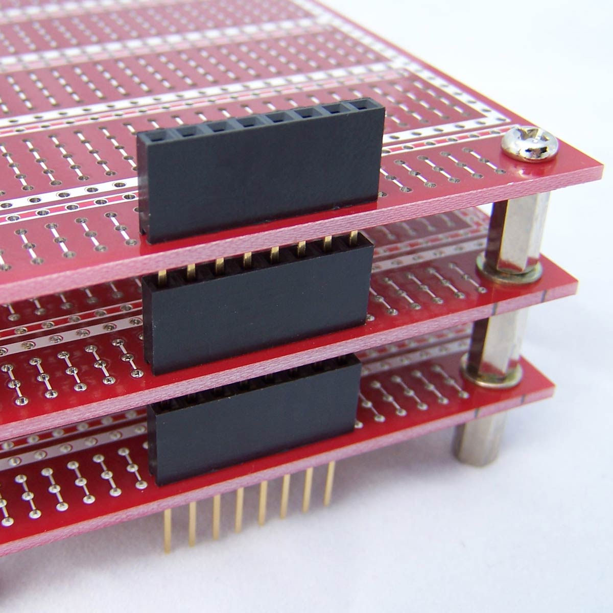 turbid trail
sly sand
Can you explain more please “sorry English is my third language”
turbid trail
sly sand
Can you explain more please “sorry English is my third language”
Here's another picture, from https://learn.adafruit.com/adafruit-proto-shield-arduino. It isn't a motor shield, but it would work the same way.
https://cdn-learn.adafruit.com/assets/assets/000/022/882/medium800/learn_arduino_2077-02.jpg?1423171307
 sly sand
turbid trail
Here's another picture, from <https://learn.adafruit.com/adafruit-proto-shield-a...
sly sand
turbid trail
Here's another picture, from <https://learn.adafruit.com/adafruit-proto-shield-a...
I couldn’t found it in my country, do you think I can just expand the pins in the breadboard? I just want to work with this robot for about 30 min for my graduation. As far as it can work, I’ll go with it and change later for best update. Can I?
turbid trail
sly sand
I couldn’t found it in my country, do you think I can just expand the pins in th...
sure, you can do that, it will just be less robust because of the wires going all over the place, so you'll have to be gentle with it
more likely a wire will come loose and it will stop working
sly sand
Okay sir I’ll do that, and will it cause any problems or any changes in the coding?
turbid trail
I don't think so, it's the equivalent wiring just done on the breadboard
electrically it can be the same
what country?
Korea?
turbid trail
sly sand
I couldn’t found it in my country, do you think I can just expand the pins in th...


 sly sand
turbid trail
what country?
sly sand
turbid trail
what country?
Morocco
sly sand
turbid trail
https://toolparts.co.kr/product/adafruit-shield-stacking-headers-for-arduino-r3-...
We have this, but where I should put it?
turbid trail
sly sand
We have this, but where I should put it?
what do you mean, you have it? Could you take a picture of the motor shield as it is now?
you have a lot of things that need to go on the breadboard anyway, so doing it as you suggested seems fine
sly sand
This one?
 turbid trail
The motor shield will not fit on the breadboard by itself, but you can use M-F jumpers from the pins on the bottom to the breadboard, and then M-M jumpers from the breadboard to the Arduino
sly sand
Yes that’s what I want to do, can it work?
turbid trail
sure it can work. you might want to use tape or something to prevent the jumpers from slipping off. I'd say mount everything on a piece of wood or similar so it's all immobilized and one thing moving will not pull on another. Unfortunately there are no mounting holes on the motor shield, it looks like
I take that back, I see one in the upper left corner, maybe there is another
sly sand
Yes I customised a piece of wood to fit in the shield inside.
Another question please, can I not plug the TX/RX of the motor shield to the arduino? I searched and it said the motor shield doesn’t use them. Is it correct?
turbid trail
could you give me a product link for the motor shield? Probably not but way to know is to look at the product documentation and/or the schematic
I think it's a clone of our very old V1 motor shield: https://learn.adafruit.com/adafruit-motor-shield

From that schematic you can see TX and RX are not being used, and A0-A5 are not being used (they don't have to be used for analog, they are fine as digital pins too).
 sly sand
turbid trail
sly sand
turbid trail
Thank you so much sir
 wary copper
I have a QT Py ESP32S3 (https://www.adafruit.com/product/5426) and seem to have broken a diode off the PCB. I've attatched images to where its supposed to be. I have tried repairing it, but with just a soldering iron and no PCB tools like a hotplate, it is proving very difficult. I assume the diode is an essential component as the device won't power up or show up on any computer. On one device which I luckly was able to repair the same issue, it fixed the problem

The ESP32-S3 has arrived in QT Py format - and what a great way to get started with this powerful new chip from Espressif! With dual 240 MHz cores, WiFi and BLE support, and native USB, this ...


Does anyone know if I can just bridge the connection with solder or if that will fry the board
inland bear
wary copper
Does anyone know if I can just bridge the connection with solder or if that will...
Ideally I wouldn't just bridge it. maybe you can fit a different larger diode by bending the legs around? I just had to do this yesterday for the diode above your missing one (mine - D2 - separates battery and 5V, whereas yours - D1 I believe - separates USB VBus and the 5v rail leading to the 3v3 LDO).
I'd prefer to not suggest bridging it, but maybe it would be okay if you never have a battery attached. Best to ask in the forums where there are adafruit staff responding.
the schematic can always be found on the downloads page of the products Learn Guide: https://learn.adafruit.com/adafruit-qt-py-esp32-s3/downloads
 wary copper
inland bear
wary copper
inland bear
thanks for this
i do use a battery but with device i wont now
ill ask in the forums tho
inland bear
wary copper
i do use a battery but with device i wont now
It seems mostly about the battery not back powering the USB port, so if never battery and USB at same time then maybe okay to bridge, but see what you get in the forums
terse forge
primal shell
I like aluminum myself, but my laser cutter doesn't cut it either, so when I wan...
oh nice, that may be the route I go after a prototype or two
 shy coral
Anyone familiar with Tower Pro servos?
I have a MG90D (360) and upon stopping it, it reverses before coming to a halt, how can I prevent this?
I have checked the signal with oscilloscope, and there is nothing wrong with it. it goes from 1ms duty to 1.5ms just fine, but the motor still "reverses" slightly before stopping. (stalled or not)
Same when turning off the output (eg, logic low on pwm pin) and given the motor is stalled, but much less.
olive light
if you mean it ovrshoots and corrects, that's normal, especially with large inertia
shy coral
olive light
if you mean it ovrshoots and corrects, that's normal, especially with large iner...
Feels weird though.
Edit: Upon touching the end switch, the PWM output is set to 1.5ms duty @ 19.96ms period. I dont understand why it reverses so much 😦
shy coral
It seems to depend on where internally it stops, different "locations" have different backlash. Feels like the internals is trying to regulate it despite bing a Continuous 360° variant...