#help-with-robotics
1 messages · Page 1 of 1 (latest)
 frosty raft
 still arrow
so I need these tires to be roughly the same size, I can remove the rubber part to get there but

then I'm losing traction, any ideas what I could stick to it to regain some traction back?
 molten jay
still arrow
so I need these tires to be roughly the same size, I can remove the rubber part ...
molten jay
still arrow
so I need these tires to be roughly the same size, I can remove the rubber part ...
Maybe you can use this fly stick thing?. Yellow sheet that has some sort of glue but rubbery
 night trout
Hey everyone! So I'm trying to use a Kalman filter to do localization of my small robot. I currently only have an IMU as a viable sensor. (I have someone who gave this project to me)
but eh it seems like I'm missing one sensor right? I have everything for the prediction step but I'm missing a GPS or Lidar or something for the update step. Not sure what to do here
 sharp solar
night trout
Hey everyone! So I'm trying to use a Kalman filter to do localization of my smal...
sharp solar
night trout
Hey everyone! So I'm trying to use a Kalman filter to do localization of my smal...
My understanding is that Kalman filters do relative localization relative to the start point usually. If you want to make it do absolute localization you can add GPS (although this may not have the required precision or accuracy), or if you want to do absolute localization relative to its surroundings you can add LIDAR but at that point you may not even need the IMU and Kalman filter
So yes, you do have everything you need to do a Kalman filter to determine relative localization
night trout
I'm not sure, I'd be okay with relative loclization. The thing is like you use the accelerometer and gyro in the prediction step right? But what measurements are you going to use in the update step? Without the update step it seems to me like errors will build up and it will drift from the truth
sharp solar
Yeah
That's the issue with Kalman filters
However
Many people do use them in robotics and they do make it work
I was working on a tunnel boring machine in college and the issue we ran into with using a kalman filter is that the whole thing was shaking so much that we couldn't get any decent info with it
night trout
oh yeah lmao I can see that happening
sharp solar
One way to get around that is to isolate the IMU with foam
Which definitely improves it

Autonomous Robots Lab
Basic Introduction to Kalman Filtering. The basic Kalman Filter structure is explained and accompanied with a simple python implementation.
Math was never really my strong suit, but I believe what the update step does is take the info from the predict step and apply it to the last known position
night trout
Oh yeah I know haha, I've already implemented it in python and cpp with a gps gyro accelero and lidar
night trout
sharp solar
Math was never really my strong suit, but I believe what the update step does is...
oh I'm pretty sure the update step is using the measurement and covariance to determine how to correct the prediction step
sharp solar
Oh I see
night trout
It's like you use the gyro (heading) and accelero to predict the next state
sharp solar
Yeah my advice would be to get as accurate readings from the IMU as you can. In the past, I've done this by taking a rolling average of the last 10-20 values and just reading very fast
night trout
and then measure with a gps or lidar and correct your prediction
night trout
Well so I'm still in high school and the husband of my principal is a software engineer so he gave me this project and told me to implement a kalman filter using the IMU. The thing is he's not very responsive on email haha, so I've asked him whether I need another sensor and he said I don't need one. Still didn't tell me how to do it with just an IMU but I have to use a kalman filter with that imu
not allowed to use lidar yet haha
sharp solar
Yeah I don't think you need another sensor
I'm pretty sure you the idea of kalman filters is you can get the approximate localization of something with just an IMU
It won't be perfect, but given that he told you to use a kalman filter, I bet he knows that
night trout
oh well
Yeah I hope so haha
the prediction step is like
x = Fx + Gu I believe
actually nvm
Anyways, everything I've found online just used the gyro and accelerometer in the prediction step but I guess I can also just use it in the update step
and make the H matrix select only acceleration and heading
sharp solar
Doesn't the prediction step give you the values that you use in the update step? Or am I misunderstanding
night trout
Yeah, you use those values together with a measurement to come to a new estimate
night trout
often people use a gps or lidar as the measurement and just use an accelerometer and gyro to make a better prediction
sharp solar
Ah
night trout
but I guess I can also use the gyro and accelerometer as the measurement and I'll just lose some accuracy which hopefully won't be too bad
 peak plume
night trout
but I guess I can also use the gyro and accelerometer as the measurement and I'l...
peak plume
night trout
but I guess I can also use the gyro and accelerometer as the measurement and I'l...
Check this out if you haven't done so: https://youtu.be/RZd6XDx5VXo

Part 1 of sensor fusion video series showing the need for combining sensor data, for example, to estimate the attitude of an aircraft (e.g. UAV) using an inertial measurement unit (IMU). Benefits and problems of typical sensors, such as accelerometers and gyroscopes. Real-world, practical considerations and demonstrations on a real-time embedded...
Part 3 gets into extended kalman filters. I watched it quite a while ago, but iirc it was quite easy to understand
night trout
peak plume
Check this out if you haven't done so: https://youtu.be/RZd6XDx5VXo
oh thanks! will definitely check it out
night trout
Alright so I use the gyro in the prediction step and accelerometer in the update step
interesting haha
One thing though... this is for attitude estimation, so for localization it wouldnt really be that useful right? Like I'm still missing a sensor or smthing
 vocal bear
Does anyone know if, as a rule of thumb, powering your servo from a higher voltage results in a higher voltage supplied to the pot?
 primal shell
The internal feedback pot in the servo? It may well be run from an internal regulator (that's the configuration the M51660L chip uses, anyway). Does it matter? I suppose it might with an analog feedback servo.
vocal bear
I'm modifying a servo to be analog feedback
They pick out the line for such in a plated through hole fortunately
primal shell
If you already have it open and are attaching wires, it should be simple enough to measure the voltage across it to find out the situation for your particular servo.
vocal bear
Ah, I don't have a higher voltage supply or else I'd just do that
I'm considering buying one, but I don't have one
primal shell
You've lost me, I figured you were supplying your servo already and wondered if the range from the pot was the supply voltage or something lower.
vocal bear
Yeah I am, I have a 5V supply but I'm considering getting a higher voltage supply and wondering how that affects the voltage supplied to the pot
 sterile summit
hey guys I am trying to design a voice coil actuator for a robotics project and I am finding it difficult to find a good positioning system. what are my options? Linear encoders are great but the position isn't absolute and absolute ones are very expensive! Any optical sensor recommendations for a displacement of 25mm?
still arrow
so i have a problem. I need to power 12v stepper motors, and a 5v arduino. Here's the thing, i connected some batteries in series which give 14v, these are connected to l298n drivers (which are connectef to the motors), should i worry about the integrity of the motors?
And how bad of an idea would it be to feed the arduino with one of the drivers? The driver has the option of providing a 5v output, but this is supposed to be when it receives up to 12v
primal shell
The motors will likely be fine with 14V (or you could use fancier current regulated drivers that would make best use of the extra voltage). I'm not sure what you mean by "feed the Arduino with one of the drivers", as I thought the signals went the other way, the Arduino sends control signals to the drivers, which then switch power to the motors.
still arrow
Well you see, the driver has input from the arduino, and output to the motors, but also has a 5v output to power a peripheral
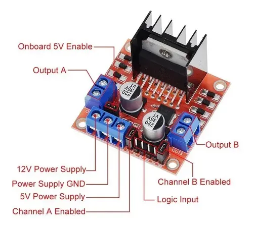
That 5v psu can be an output when using the other one to power the driver
 primal shell
Ah, I didn't know you had a whole board with a power supply. Yes, it should be workable to power the Arduino with the 5V supply provided by the driver board.
still arrow
Oh, only seeing your message now
Ive connected the motors to the l298n and i find they get really hot really fast
primal shell
Yeah, if they're stationary, they'd probably be drawing too much power
still arrow
These batteries are discharging way faster than expected
primal shell
That's when smarter stepper drivers come in handy, they use pulse width modulation to vary the drive signal to control the current through the motor, and can even reduce the drive when the motor isn't moving.
For battery use, it is often reasonable to accept greater complexity as the cost for more efficiency. That linear regulator is also going to waste a large amount of power.
primal shell
While you could drive the L298 with PWM generated by your Arduino, it would be tricky to figure out what duty cycle is needed at any given moment.
The fancier chips include current monitoring and closed loop control so they can manage that automatically. To do with an Arduino, you'd have to build the current monitoring circuitry yourself, and figure out how to use it to modulate the PWM as needed.
still arrow
😔
primal shell
I know that feeling. I ended up having to build a completely custom board model and memory map for one battery operated project in order to get the performance I wanted.
still arrow
Steppers should move clockwise when getting a positive value, right?
primal shell
Not really, they're synchronous motors, so they'll move whichever way the magnets and fields align.
still arrow
Hmmm, well but i think it's the way thus library (accelsteppper) handles it
primal shell
Even "a positive" value has little meaning with a stepper. Normally there are two sets of coils, and powering them in one order turns one way and the other order turns the other way. It's further complicated by the fact that some steppers are unipolar, so the electricity always flows the same way, but others are bipolar, so the electricity reverses periodically as the signals cycle.
 maiden pebble
2 Questions for the group re unobtainium:
- nVidia Jetson: It's been a while since I've heard anything. Does anyone know if there is any relief on the horizon?
- BNO055, I saw that the BNO085's are available and I was thinking of writing a wrapper of the cp driver to translate the 85 to common 55 calls, e.g. euler orientation. Does anyone know if such code already exists? If not is that something this community would be interested in?
 dusky flame
I am trying to controllservos over USB and i2c with the PCA9685 and while it works with I2CMini by Excamera Labs it seems to be very slow. I now also ordered the Adafruit MCP2221A Breakout is that potentially fast then the I2CMini? I am trying to update the servo positions about 24/s . Thanks for any thoughts and insights.
||Originally I was using the RPIs internal I2c port who handled this without a problem. but due to their availability I needed to switch to controlling things through a virtual-box Linux. ||
 topaz grail
dusky flame
I am trying to controllservos over USB and i2c with the `PCA9685` and while it w...
topaz grail
dusky flame
I am trying to controllservos over USB and i2c with the `PCA9685` and while it w...
I'm using the MCP2221A with a PCA9685 , so I might be able to give you some useful info. (I'm also trying to move things at 24fps lol)
First of all, here's a forum post that indicates the MCP2221A has latency issue with i2c. If the problem is circuitpython related, the issue may apply to your I2CMini as well: https://forums.adafruit.com/viewtopic.php?f=60&t=168835&p=826229&hilit=MCP2221+i2c#p826229
Using the following snippet, I time how long it takes to update one channel of the PCA9685 over i2c using MCP2221A:
start_time=time.time()
pca.channels[7].duty_cycle = 0xFFFF
print('Time to set duty cycle for one PCA9685 channel: ', time.time()-start_time)```
and get the result:
```Time to set duty cycle for one PCA9685 channel:  0.008001089096069336```

Additionally, if you are using `ServoKit`  to set the angle of your servos, here's the timing for that:
```py
start_time=time.time()
brows.servo[0].angle = 50
print('Time to set one angle using ServoKit: ', time.time()-start_time)```
results in:
```Time to set one angle using ServoKit:  0.0359959602355957```
I'm pretty sure this means you'll be able to update one servo at up to about 27 frames per second.

If you run the same timers using your `I2CMini`, perhaps you'll be able to tell if the `MCP2221A` will be faster for you.

Finally, I'll note that the motorkit api (https://docs.circuitpython.org/projects/motorkit/en/latest/api.html) has this to say:
```board.I2C() uses the default I2C bus frequency of 100 kHz. To speed up motor control, use an I2C bus frequency of 400 KHz, or if available, 1 MHz. The PCA9685 controller supports both of these higher speeds. This will noticeably speed up stepper motor operation when many steps are requested.```
...yet, when I've run my timing tests trying different i2c speeds (by using `i2c= busio.I2C(board.SCL, board.SDA, frequency=400000`) I always get the same result.Hey! does anyone know whether ROS works with arch? Online it says it supports Ubuntu fully and others to a certain degree but I have no idea how large that degree is haha
 manic depot
You would have to go through the "Install from sources section" thought. Not sure If it's worth
 vestal rose
Hi all,
I am using the following code https://github.com/raspberrypi/pico-examples/blob/master/i2c/mpu6050_i2c/mpu6050_i2c.c
for a RPi Pico
The MPU6050 data I get are raw.
how do i go about sanitise them ?
Currently it looks like it
AX:296 AY:-1308 AZ:15160 GX:-130 GY:137 GZ:108 T:0.00
AX:428 AY:-1268 AZ:15212 GX:-126 GY:146 GZ:124 T:0.00
 lone skiff
Typically you'd just scale them based on the range for the sensor. For example, it's likely that the accelerometer is set to +/- 2g range with a 16-bit data value (-32768 to +32767), so the 15212 number would correspond to about +0.93g. There may be multiple possible ranges, so you'd need to check against the datasheet and the code you're using to be sure what it's set to by default.
vestal rose
lone skiff
Typically you'd just scale them based on the range for the sensor. For example, ...
aw, sounds easy 😄 😄
erm, is there a way to detect the range and the bit the mpu is configured ?
primal shell
If you look at the AdaFruit library for it, you can see some nice example code in the read routine showing how it uses the ranges to figure the scaling: https://github.com/adafruit/Adafruit_MPU6050/blob/master/Adafruit_MPU6050.cpp#L630
lone skiff
vestal rose
aw, sounds easy 😄 😄
erm, is there a way to detect the range and the bit the ...
Yes, there are registers you can read back to check that.
vestal rose
aw. worth mentioning, i am noob, so reading the Adaf code is not my cup of tea 😄
primal shell
It is the nice thing about open source, being able to see how the code gets the raw values and converts them into the desired units. It's not even complicated, it figures out the scale factor and then divides by it: ```arduino
accX = ((float)rawAccX) / accel_scale;
yeah seen that !
but i am not too sure on the accel_scale :/
again, sorry being total noob on that !
primal shell
There's no shame in being a beginner: we all start as beginners.
vestal rose
usually i wouldnt dig into it cause I would use Arduino and never worry abt the library, now I write C on a Pico 😄
primal shell
However, to answer your question on how to sanitize the raw values is going to require some concepts like the range registers on the chip
You can nearly use the AdaFruit library as-is. It's written in the Wiring language the Arduino uses, which is just a dialect of C++, which in turn is a version of C. So you'd have to replace stuff like void Adafruit_MPU6050::_read(void) { with the simple C version which could be like void MPU6050_read()
But most of the action code is valid C as it is, so you can just grab and re-use it.
vestal rose
let me give that a go 😄
primal shell
I'll admit I often use that fact to go the other way, and just program my Arduinos in C, and don't use the C++ features.
vestal rose
Lol
 mossy elbow
Today's JP product pick was a neat motorized slide potentiometer. Some folks mentioned motorized rotary potentiometers and "Analog Feedback Servos" being a thing.
Curious, what's the stepper motor equivalent(s), "Closed Loop Stepper" and/or something else?
Am wanting to record and playback position of Stepper motor => gear => belt driven contraption. Cheers!
vocal bear
With steppers don't you usually just record the steps in software and calculate from there?
I googled it
The answer is what I should have guessed. Encoders
Looks like you use them for handling missed steps
primal shell
There are servos with position feedback as well
primal shell
AdaFruit offers a few of them, here's one: https://www.adafruit.com/product/1449

It looks like a micro servo, it acts like a micro servo, but it's more than just a micro servo! We got a factory to custom-make these classic 'micro' sized hobby servos with a ...
mossy elbow
Yep, e.g. bigtreetech S42B "Closed loop stepper" are used to help avoid layer shifts during 3D prints by detecting and compensating for missed steps.
Am wanting to let a user move record moving a gantry/contraption around that's normally stepper motor driven. Then have the motion be played back.
vocal bear
primal shell
AdaFruit offers a few of them, here's one: https://www.adafruit.com/product/144...
At least a few normal servos can be modified to be feedback easily
Some with more difficulty
primal shell
You can always lash a potentiometer or encoder to one either directly or via belts/gears/whatever.
mossy elbow
primal shell
You can always lash a potentiometer or encoder to one either directly or via bel...
Thanks @vocal bear and @primal shell. Am digging/searching around to learn more about closed loop steppers like Bigtreetech S42C V1.0, then figure out whether to use existing stepper with integrated encoder, or, go off and design, build and hack something. Cheers!
vocal bear
Good luck!
vestal rose
primal shell
You can nearly use the AdaFruit library as-is. It's written in the Wiring langu...
Dude tbh I could not figure that out. :(,
primal shell
You can simplify it, since you presumably know which ranges you want to measure, so just send the commands to configure those ranges, then you'll already know the figures to divide the raw values by to get the values in the final units.
 lime oar
I have one of those MKS TMC2209 V2.0 breakout boards to use in a legacy piece of equipment that relies purely on full steps (no microstepping).
i.e. 200 pulses on the STEP pin should result in 1 full 360° revolution on the standard 1.8° stepper.
however the motor is only turning 1/8th of what it should be irl. Implying even when MS1 and MS2 are LOW, the driver is still requiring 8 pulses per hardware-step. what gives?
primal shell
I think that driver allows both OTP and command sequences to override the configuration inputs.
lime oar
primal shell
I think that driver allows both OTP and command sequences to override the config...
How can i adjust via OTP or UART? all the help articles I see involve the use of a 3d printer main board. I just have an Arduino and a few serial adapters.
lime oar
got this far so far

 lime oar
I can write to mreg and mstep_reg_select, but it doesnt save after power off
it reads after writing though
 oblique pagoda
the datasheet says the registers are erased when powered off
like normal registers usually are
seems like you'll need some kind of setup routine to set them as needed
primal shell
It you actually want to permanently write the OTP bits, you need to use the magic code. I'd be wary of doing so, as they're only programmable once.
However, if you want to do it that way for operation without a setup routine, it should be possible.
 placid jetty
Anyone using ROS2 on Arch linux?
placid jetty
never mind. Got it working
 plush spear
On Adafruit's DRV8833 breakout board, can the AS and BS pins be used to measure the current flowing through the DC motor?
 heavy osprey
Hey anybody got suggestings for a driver for Adafruit MLX 90640 on ESP32?
I have an ESP32 dev kit board and want to use it to get data from it over I2C
I have successfully used the repo here on raspberry pi https://github.com/adafruit/Adafruit_CircuitPython_MLX90640

GitHub
A pure Python MLX90640 driver. Contribute to adafruit/Adafruit_CircuitPython_MLX90640 development by creating an account on GitHub.
Now I need a fork for ESP, which seems much harder given it runs on CircuitPython
placid jetty
plush spear
On Adafruit's DRV8833 breakout board, can the AS and BS pins be used to measure ...
As I read it on the bottom of page 10 of the datasheet (https://cdn-learn.adafruit.com/assets/assets/000/039/902/original/drv8833.pdf?1488941266) these pins are used to control the max current and not sense it.
placid jetty
heavy osprey
Now I need a fork for ESP, which seems much harder given it runs on CircuitPytho...
isn't the arduino library working for the ESP32? Atleast it should be an easier starting point to write something for ESP32.
placid jetty
hmm. I never translated circuit to micropython, but it should be possible.
If you know how to get some I2C working you'd just have to copy the protocol for this sensor
heavy osprey
placid jetty
If you know how to get some I2C working you'd just have to copy the protocol for...
I have looked at the cicuitpython implementation as it is (luckily) not very complicated,
worst comes to worst I could just fork it and re-implement what I need
placid jetty
yeah, I initially didn't get that you are using micropython on your ESP32
night trout
Hey any tips on managing cables? I have like a plate and some cables are a little too long so should I just cut them or use something (what?) to keep them neatly in place
(small cables haha, amateur robotics here)
 modern pulsar
Zip ties are an option. With smaller cables you could loop them up, and use shrink wrap as well. Shrinkwrap the loop together. Would make it look neater for sure.
modern pulsar
night trout
Hey any tips on managing cables? I have like a plate and some cables are a littl...
Cutting and soldering them is an option, but would involve shrinkwrap anyway, if you were keeping it clean, so maybe try shrinkwrap first?
night trout
hmm shrinkwrap seems interesting! The cables are quite short tbh, we're talking about 3 cm that's a little off that's annoying me haha, should be able to use shrinkwrap though
or just some tape
modern pulsar
Also valid!
oblique pagoda
probably meant to be wired to one of their priorietary board since the kit contains 2x gravity cable which explain the wiring
but I'm very puzzle how that's supposed to be installed, even checking the manuals for the robots that have it as an optional part
primal shell
Looks like the white connector is the outputs, which connect to GPIO 0 and 1 (for the DFRobot board) or 2 and 3 (for an Arduino)
placid jetty
night trout
like where is the wiring
The pinout of the board is on the PCB itself. kinda hard to see from the images. I think its: 1 signal, 2 VCC, 3 GND and that would match the colors on the wires nicely (green: signal, red: vcc, black: gnd). VCC should be 5V from the description and I'd guess signal will be 5V then as well. But even if it's 3.3V it should work with 5V controllers.
you need double shaft versions of the motors to use these
night trout
placid jetty
The pinout of the board is on the PCB itself. kinda hard to see from the images....
Sorry for the late answer, so I should be good giving the motors external power supply and for the encoders the 5V from the adafruit motorshield on an rpi right?
There are so many wires haha
primal shell
night trout
Sorry for the late answer, so I should be good giving the motors external power ...
Yeah, that is a popular approach and should work well, just need to make sure the 0V references are all tied together so the current through the various loads can return to the right power supplies.
placid jetty
night trout
Sorry for the late answer, so I should be good giving the motors external power ...
Yes, you can power the motors however you want, since they are not electrically connected to the encoders. The encoders need to be on the same ground as the controller/raspberry and connected to some 5V source.
So yeah, you can connect all the wires from the encoders to the shield/raspberry. Just make sure to have enough Amps if you keep adding stuff. But 2 encoders should be no problem.
Oh, wait. The raspberry has 3.3V IO right? So you shouldn't connect a 5V signal directly. (Although I did it once on accident and it was ok some how)
You should check if the signal level is 5 or 3.3 from the encoders. If it's 5V you can test if they still work when only powered with 3.3 or add a voltage divider using 2 resistors between the encoder signal line and the pi
night trout
Alright, I'll try everything out now, thanks a lot!
maiden pebble
Bump detection with BNO055?
I use a BNO055 for orientation on my robot. I've got all kinds of obstacle avoidance (TOF, camera, ultrasonics), but sometimes, the bot just doesn't see something and bumps into it. I considered using a vibration sensor, but I want to know if anyone has used raw accelerometer readings from the BNO055 to detect bumps and collisions. If so I'd be interested in getting pointed to any reference code. Otherwise, I might just try to write something for myself (look for acceleration spikes when the bot expects to be moving forward, or something).
Thanks!
oblique pagoda
maiden pebble
Bump detection with BNO055?
I use a BNO055 for orientation on my robot. I've g...
@maiden pebble bump detection is last resort, it should be REALLY simple, a inverted pushbutton with a bumper will do the job fine also "Build or buy a bumper and get a bumper behavior working. This is the "sensor of last resort" that will save and protect your robot when all other sensors fail or misread. The classic bump-and-run algorithm is a good place to start. If bump is on the right, stop, back up, turn left a bit, go forward a bit, release control. Same if bump is on left. If bump is in center, it's not so obvious what to do, so it invites creativity."
 rough cave
maiden pebble
Bump detection with BNO055?
I use a BNO055 for orientation on my robot. I've g...
rough cave
maiden pebble
Bump detection with BNO055?
I use a BNO055 for orientation on my robot. I've g...
I recommend that even though you can find examples, you still have to base it off of your feedback, because there are a lot of variables between systems and as far as shock and vibration are concerned. and it sounds like you already know how to communicate with it. the important things in my opinion are duration and magnitude (shhh is that all it does? lol)
placid jetty
maiden pebble
Bump detection with BNO055?
I use a BNO055 for orientation on my robot. I've g...
The tricky part is, that a bump is a pretty sharp deceleration. So if your readings arn't coming in fast enough you'r gone miss it. As far as I know BNO055 isn't the fastest sensor and the MCU behind the sensor needs to keep up with the speed as well. My suggestion would be to record or display the data in real time (as fast as you can), make a few bumps and check if you can see them reliable in the readings. If you see a spike, it should be at least 2 readings long so you know you can't miss it if the bump falls in between the readings.
It's a lot of trouble and likely not reliable in the end. I think a switch would be easier.
lone skiff
I'd generally expect that the BNO055 also has a tap-detection feature built in which you can set a threshold to trigger an interrupt flag, or something similar.
placid jetty
Here is also a secret tip from me: Look for a very sensible pressure sensor that allows you to attach a tube to it. Now close that tube at the other end. If the tube is squeezed or bend, the pressure will rise slightly (requires really sensitive sensor). This can be used for very flexible bumper arrangements.
lone skiff
placid jetty
Here is also a secret tip from me: Look for a very sensible pressure sensor that...
Clever! That's going in my bag of tricks...
placid jetty
lone skiff
I'd generally expect that the BNO055 also has a tap-detection feature built in w...
Actually it has that option. 3.8.2.4 Accelerometer High G Interrupt
But I guess it still depends on the internal sensor speed, but that should be high enough?
 pastel zodiac
Ok I'm planning out a new robot. It's going to rove on a pair of brushless motors (no problem there) and simultaneously wave about 18 little flags. Ideally those flags would wave asynchronously, but I do t want to have to carry 18 separate motors, so I'll configure them in 2-4 banks on cam shafts, mounted at slightly different rotations on the cam. No worries yet. I want to retract those flags into a stowage position; the cams will ride on a moving floor, pulled up and down by linear actuators. Still no biggie. The tricky bit is I want the flags to halt in a specified position before retracting. That suggests the cams are each driven by a closed loop motor. So the question (finally) is, will it be easier to use a stepper with rotary encoder, or a continuous servo?
primal shell
pastel zodiac
Ok I'm planning out a new robot. It's going to rove on a pair of brushless motor...
A stepper will have a known position (unless it misses steps for some reason), so doesn't necessarily need an encoder. Other types of motors would need an encoder to figure out their position. I'd kind of lean toward an ordinary DC motor plus an encoder as the easiest solution but I'll admit I'm just guessing.
Or even an index switch to detect when it's at a given angle, you don't really need a whole encoder.
 shy dock
Can anyone identify the name of this treads kit or company selling them?
 shy dock
Never mind, I’ve found vexrobotics. Their website is currently down so that’s why I couldn’t find them
 lapis gyro
yeah, that looks like vex to me
 pulsar pebble
pastel zodiac
Ok I'm planning out a new robot. It's going to rove on a pair of brushless motor...
pulsar pebble
pastel zodiac
Ok I'm planning out a new robot. It's going to rove on a pair of brushless motor...
A continuous rotation servo or a stepper both would serve the same purpose but stepper can also do micro steps with the right driver. You’ll want to look at weight/size/resolution/cost to fit your needs.
pulsar pebble
primal shell
Or even an index switch to detect when it's at a given angle, you don't really n...
There are cheap encoders out there, too. The thing with encoders+dc motor is that OP will have to make their own PID control loop. Sounds like overkill for tiny flags. Steppers/servos already have that built-in
pulsar pebble
maiden pebble
Bump detection with BNO055?
I use a BNO055 for orientation on my robot. I've g...
Why not use one of the new accelerometers that already has tap detection built into the sensor chip. Like the LIS3DH
pastel zodiac
pulsar pebble
There are cheap encoders out there, too. The thing with encoders+dc motor is tha...
Yeah the PID tuning is a turn off. I think I'll use a stepper. Next trick is wrapping my head around the i2cperipheral protocol so I can have the stepper run in parellel to what the Grand Central is doing.
pulsar pebble
pastel zodiac
Yeah the PID tuning is a turn off. I think I'll use a stepper. Next trick is wra...
Is there a special protocol? Steppers don’t use i2c, they need a stepper motor driver.
pastel zodiac
It'll be grand central -> feather (via i2c) -> stepper featherwing. I need the stepper to keep moving while other code runs, so have to offload it to a peripheral board.
lone skiff
pastel zodiac
It'll be grand central -> feather (via i2c) -> stepper featherwing. I need the s...
BTW, it is possible to have stepper drivers run in parallel with other code with interrupts and so forth, but that might not be immediately supported in off-the-shelf libraries.
pastel zodiac
Interesting! But possibly more advanced than my current skill level. I'm barely out of Circuitpython basic education.
primal shell
I'm unsure if a Feather can act as an I2C target and an I2C host at the same time
pastel zodiac
I'm not sure either. My backup plan is to just send signals via the digital in/out pins, but that's more clunky.
lone skiff
pastel zodiac
Interesting! But possibly more advanced than my current skill level. I'm barely ...
Yeah, that would be more of a lower-level C thing instead of CircuitPython, gotcha.
placid jetty
The problem with steppers is, that you need to keep them powered even when you not use them or have the risk to loose steps.
So I generally prefere encoders for mobile/battery powered projects
pastel zodiac
placid jetty
The problem with steppers is, that you need to keep them powered even when you n...
Agreed. But I haven't done PID tuning in decades, so I'm a bit intimidated by that option. Any good suggestions on an up to date tutorial? Also, any suggestions for a small encoder? (if I go DC, I'd probably use something that can do about 60-120rpm at fairly low load, less than a kg-m of torque required).
pastel zodiac
What if I used a 12V DC motor with appropriate gearing, add a tab on the axle, and use something like this as an index switch? https://www.jameco.com/z/H21A1-Isocom-Components-Photointerrupter-IR-3mm-Slot-150mW-Tab-PC-Mount_114091.html I’m mostly thinking out loud here, I think it is a better solution. But I’d love y’all’s input.
Isocom Components H21A1 Optical Switch. Products in stock and ready to ship. Quotes, samples and datasheets available at Jameco Electronics.
placid jetty
If you just need to find a single position it's easiest to attach a magnet to the shaft and use a hallsensor. It's more easy to get reliable than something optical or mechanical on a DIY build
An index switch (or single step encoder) has the benefit, that you don't need to keep track of the steps made during the runtime.
PID isn't to hard. Actually often a P controller is sufficient. Usually a PD if fine if you don't need high accuracy. Finding the right values will require some testing thow
Just @ me when you need help
 sly sand
I'm not sure what to look for
isn't like possible to get a rig (like a maya rig, usually used for animation), and then use that rig to animate a robot?
 silk ferry
Hi everyone. I would love to be able to get some help making a robot. I have some experience with electronics, but none with robots. I've starting reading and learning, but I'm just at the stage where I'm starting to realize how little I know and how much there is to learn! For the past few years, I have been working on a team to make a block-based programming environment, with a particular focus on supporting students with disabilities. At the moment, you can move a character on screen under control of your program. What I'd love to make is a robot that I can connect to over Bluetooth and have it move together with the character on screen. At the moment, the movements possible in the programming environment are moving forward and backwards, and turning left and right (turtle graphics style movement). My idea would be to make a robot that I send these movement messages to over Bluetooth and it does each one as it receives it (and provides feedback when it's finished, so I can synchronize the robot and the on-screen character). Ultimately, it would be awesome to put together instructions, or a kit, so that educators and families can make their own robots, but for now, making one would be a great start!
primal shell
That sounds totally doable, not too complicated or expensive. There are even some robot control boards/modules that integrate a microcontroller with Bluetooth capability with some motor drivers.
silk ferry
That would be awesome. I've been looking at some of the boards, motors, and chassis available on Adafruit, but I don't have a good sense of how to pick parts that will do what I want. For example, would a DC motor or continuous servo be more suitable?
primal shell
The basic difference is the continuous rotation servo has its driver electronics onboard and can be directly controlled by a microcontroller. A DC motor has no smarts, so needs an external driver. My personal preference is for external drivers, which gives a greater choice of motors, and the drivers can be integrated into a control board like the ones I referred to previously. There are also modular approaches like shields where you simply attach a motor driver board to a microcontroller.
silk ferry
Cool. And for a DC motor, for this application would I need an encoder to know how many rotations the wheels have made, so that I can move and turn accurately. Or would simply timing how long I have the motor on for be accurate enough? I'm thinking for example that how fast the motor turns might depend on the surface or battery voltage? Or are there better ways of measuring distance moved or angle turned? (I mention an encoder above, but my understanding here is very minimal, it's just something I read about looking at available boards!)
BTW thanks so much for your help!
primal shell
Odometry is a can of worms. Even if you know how many rotations the motor makes, there's wheel slip and so forth to contend with. There's a limit to the amount of accuracy you can achievely easily and cheaply.
By way of illustration, here's a simple robot I built a while back out of an ESP module plugged into an ESP12E Motor Driver shield that controls the two wheel motors (there's a caster in the front as the third wheel).
 primal shell
The boards up top on the green breadboard were added later, they include an IMU to try to figure out heading and a display to show it (a fun experiment that didn't end up working very well)
primal shell
sly sand
I'm not sure what to look for
isn't like possible to get a rig (like a maya rig,...
I'm not sure what you're asking. A real physical robot, or a virtual one (I thought Maya was a piece of animation software)?
silk ferry
Would I be correct in thinking that the most straightforward approach to moving a certain distance, or angle of turn, would be to run the motors for a set amount of time? What kind of accuracy do you think would be realistic using this approach? I very much appreciate your help!
primal shell
Accuracy is likely to be somewhat disappointing, different motors achieve different speeds at the same voltage, and it varies by direction as well. Encoders do help to eliminate one source of errors, but the coding of the feedback loop is somewhat complicated.
There's a lot to be said for "try it and see", however. Maybe having the on-screen robot be accurate and the mechanical real-world one less so might be sufficient?
There's a similar build described here, which can yield some useful ideas: https://learn.adafruit.com/bluefruit-feather-robot

Adafruit Learning System
Control this tiny 2-wheel drive robot with your phone!
sly sand
primal shell
I'm not sure what you're asking. A real physical robot, or a virtual one (I tho...
a real physical robot
like a get a rig, and then use it to make the robot move in that way vs individually programming joints or whatever to accomplish movement
silk ferry
primal shell
There's a lot to be said for "try it and see", however. Maybe having the on-scr...
I think there's definitely some flexibility in terms of accuracy of the robot movement, but it's hard to know exactly where the limits are: how much variability is too much.
sly sand
also indeed maya is a 3d suite also used in animation
primal shell
When you say "a rig", what do you mean? You can use feedback servos like https://www.adafruit.com/product/1404 to read back what joint activities are required for a given movement.

It looks like a servo, it acts like a servo, but it's more than just a servo! We got a factory to custom-make these classic 'standard' sized hobby servos with a twist - the ...
silk ferry
primal shell
There's a similar build described here, which can yield some useful ideas: http...
Thanks very much for the link! I'll have a read at it.
sly sand
primal shell
When you say "a rig", what do you mean? You can use feedback servos like https:...
a rig is basically a skeleton which can be used for animation, it basically stores motion datas
you can recycle rigs between models, or even get a new rig from motion capture
so rather than programming individually each component to archive movement, I would like to use like a rig to accomplish the same thing with less bother
 primal shell
There are approaches such as "inverse kinematics" you can use to describe the motion you want and decompose it into the necessary joint motions to achieve it, but I'm unsure if that's the sort of thing you're looking for here.
 vagrant thunder
sly sand
I'm not sure what to look for
isn't like possible to get a rig (like a maya rig,...
vagrant thunder
sly sand
I'm not sure what to look for
isn't like possible to get a rig (like a maya rig,...
If your rig accurately reflects your robot skeleton, you might be able to directly convert your joint motions to servo or stepper commands. https://hackaday.com/2022/05/11/animate-your-robot-in-blender/ shows an example of this with blender instead of maya, but I’m sure maya would have an analogous process for extracting these motions to a bvh or csv file.
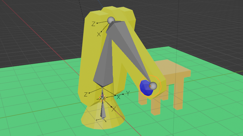
You’ve built a robot crammed full of servos and now you settle down for the fun part, programming your new dancing animatronic bear! The pain in your life is just beginning. Imagine that you …
It’s been done fairly extensively with industrial robot arms in particular. Not sure what your application is, but if it’s specifically an off the shelf industrial arm, https://www.mimicformaya.com/ is a plug-in someone wrote specifically for this purpose.

Mimic
Mimic is a free, open-source plugin for industrial robot control in Autodesk Maya. It allows for the simulation, programming, and control of industrial robots via Maya's suite of professional animation tools.
Probably not useful for a broader range of robots, but proof that what you’re imagining definitely exists and is both sound and feasible.
 whole rune
silk ferry
Hi everyone. I would love to be able to get some help making a robot. I have som...
whole rune
silk ferry
Hi everyone. I would love to be able to get some help making a robot. I have som...
not sure if this helps, but i bought one of these to play around with: https://www.sunfounder.com/products/picar-x - requires a raspberry pi but includes a pi HAT for motor/servo controls + other stuff like camera, sensors, etc. it includes some servos for a pan+tilt camera, camera module for pi etc. it lets you write simple python code to move it and it also works via bluetooth. there's a ton of similar raspberry pi and arduino small cars out there, but you mentioned servos and stuff.
in my case i'm just using the motor hat directly and using it on a much bigger rover i made, and instead of bluetooth i'm using wifi and i'm streaming it straight to the web in real timei made a little web page to drive it. major work in progress 🙂 http://www.drivearobot.com/rover.html

SunFounder
SunFounder PiCar-X is an AI self-driving robot car for Raspberry Pi, on which RPi works as the control center. The mounted camera module, ultrasonic module, line tracking module can separately realize the functions of color detection, face detection, automatic obstacle avoidance, automatic line tracking, etc.
Drive an internet connected, remote controlled rover and boat
silk ferry
whole rune
not sure if this helps, but i bought one of these to play around with: https://w...
Thank you very much! I will take a look at these.
sly sand
vagrant thunder
If your rig accurately reflects your robot skeleton, you might be able to direct...
thanks to both
googling I also found stuff like isaac by nvidia and gazebo
might I ask what differs?
vagrant thunder
Not familiar with specific tools, I’m afraid. Just general concepts from too much miscellaneous reading in my downtime.
 uncut token
Hi. I have a project with a battery powered ESP32 and a servo. My battery will be a 2S LiPo ( ~7.4v nominal). I have a voltage step down to step the voltage of the battery from 7.4 to 3.3 for the board, but the servo will need the full battery voltage to operate. I should be able to do this by connecting the battery + directly to the servo, and then the grounds of the board, battery, and servo together right? None of the examples I've found online have a voltage regulator in the circuit so I just wanted to make sure before I potentially blow up my board, servo, voltage regulator, or all of them at once 😆
lone skiff
uncut token
Hi. I have a project with a battery powered ESP32 and a servo. My battery will ...
Yep, that sounds reasonable to me.
primal shell
Most buck regulators are "non isolated", meaning they share the 0 volt reference ("ground") between their input (your battery) and output (your ESP32) so they're already connected. Connecting them then won't change anything nor cause any harm. A few are "isolated", offering separate grounds, but they won't be harmed by connecting the grounds either, it's just using a more-complicated isolated converter as a non-isolated one.
uncut token
Okay! Thanks
 frosty bronze
Hi! I'm working on a project and all of our sensors are running on 5V logic, but the Adafruit Feather STM32F405 Express apparently works on 3.3V. It says "almost all pins are 5V compliant", I was wondering which ones specifically were not? Would I be good to set up a 5V logic I2C bus and a 5V SPI line? Thank you!
vagrant thunder
frosty bronze
Hi! I'm working on a project and all of our sensors are running on 5V logic, but...
Of the IO pins, only A0 and A1 pins are definitely not 5V tolerant. I’m not sure if A4 and A5 are or not, as the data sheet suggests it might be okay, but is not specifically labeled 5T in the feather schematic. I believe you can create 5v SPI/I2C lines as long as you disable the internal pull-ups and add your own externally, but I don’t have any personal experience with this controller myself so don’t simply take my word for it…
https://learn.adafruit.com/adafruit-stm32f405-feather-express/downloads for reference sources

Adafruit Learning System
ST takes flight in this fantastic Feather board with STEMMA QT
 clever portal
Hi, I'm trying to get a RC servo to work using my UNO, the servo I'm referring to is a SW-0230MG. I tried the sweep script and it moved for a second and has not moved any more, but I can hear a buzzing inside the servo. I switched the servo out with a basic SG90 to test if I had broken anything on my board, but the sweep function worked perfectly with that servo. Is the RC servo underpowered or did I break it?
p.s. the first time I did try to power the servo directly from the 5V pin on the Arduino
primal shell
Note that the servo power supply and the servo control signal need to share a common reference (connected to the 0V lead on the servo).
clever portal
primal shell
Note that the servo power supply and the servo control signal need to share a co...
I'm really new to all this, could you explain a little more?
lone skiff
clever portal
I'm really new to all this, could you explain a little more?
There's no such thing as a "5V wire", only a wire which has a voltage that's 5 volts higher than some other wire. Usually, everything is in reference to "ground", which we call 0 volts. For two devices to meaningfully communicate, they will often need to have the same ground reference. So madbodger was asking you to check and make sure that the power supply for your servos and the power supply for your Uno have their grounds connected together. Otherwise the servo won't know what to make of the signal the Uno is sending it... it could read as 34V or something random.
clever portal

This is how I currently have it wired, but I don't know if it falls onto what you are telling me
clever portal
nvm I had a bad servo but I get it now thank you!
 uneven island
Thanks again Adafruit community for all you do with making this a great place to learn.
- what is the most powerful motor available on adafruits page?
primal shell
First, you'll need to define what you mean by "powerful". Do you mean torque, speed, or torque * speed? Also, running torque or stall torque?
uneven island
@primal shell I mean if we’re talking about making dreams come true I’d like it to go at least 15 mph and pull at least 300 lbs. I’m not sure how that plays into torque and speed.
lone skiff
uneven island
<@348911944486486016> I mean if we’re talking about making dreams come true I’d ...
So that's on the order of about 10 horsepower, i.e. a pretty substantial motor needing kilowatts of power. I don't think Adafruit generally stocks stuff like that.
 earnest oxide
At that point it might be worth using an e-bike motor. Or motor assist wheelbarrows.
primal shell
uneven island
<@348911944486486016> I mean if we’re talking about making dreams come true I’d ...
Most of the motors AdaFruit sells are for indoor type small robots. However, this surplus motor might suit your use case, the price is right, and it comes with a built-in speed controller: https://www.allelectronics.com/item/dcm-2460/24-vdc-brushless-motor-600-watt/1.html

All Electronics Corp.
MAC-BMC P/N 12570-3. Powerful brushless motor with built-in 30A motor speed controller. Designed for electric scooters. Great low-end torque. Requires 5K Ohm potentiometer or Hall-effect throttle to interface with speed control. Great motor for battlebots, hobbyists and experimenters.• No-load Specs: 2480 RPM @ 24.6 VDC, 3A 100 kV•...
uneven island
Thanks for the help everyone! Much appreciated! It put me in the right direction. I’ll keep ya updated on my project 👍🏽
 mortal dagger
vagrant thunder
Of the IO pins, only A0 and A1 pins are definitely not 5V tolerant. I’m not sure...
mortal dagger
vagrant thunder
Of the IO pins, only A0 and A1 pins are definitely not 5V tolerant. I’m not sure...
The source of the "ESP are 5V tolerant" statement always made me nervous.
An off-the-cuff remark on facebook by an espressif manager.
silk ferry
I bought some parts from Adafruit to build a 2 wheeled robot. I got a couple of the plastic "TT Motors" and I'm wondering about the plastic part wrapped around the top and the zip tie. They make it so that I cannot attach the motor flush to the side of the chassis that I got. I'm wondering what purpose those serve and if they can be removed? You can see them in this photo of the motor on the Adafruit site https://cdn-shop.adafruit.com/970x728/3777-02.jpg
 vagrant thunder
I don’t know about the top plastic, but the ziptie also serves to provide strain relief for the wires that are otherwise just directly soldered to the motor itself.
silk ferry
Thanks very much. What I didn't realize until just now is that one side of the top part is offset from the side of the motor body (on the right in the photo above). And if I leave the zip tie on but just rotate it so that the connector part is on the other side, then it will attach flush. I'm a total beginner at this stuff.
 shell wharf
could someone explain this line about the voltage for this motor?
https://www.adafruit.com/product/4411
I read https://electronics.stackexchange.com/a/559632/169864 but are there any other recommended sources to help explain?
I want to understand the relationship better so I can be confident in the voltage regulator I use to power the motor (Im looking here: https://www.pololu.com/category/131/step-down-voltage-regulators)
primal shell
shell wharf
could someone explain this line about the voltage for this motor?
https://www.a...
Motors (especially stepper motors) are current operated devices (or, more precisely, they're operated by shifting magnetic fields that are created by current flowing in wires). There are four major ways of controlling current. There's the resistive approach, where the voltage supplied drives a current through the resistance of the windings (and control circuitry) based on Ohm's law. This is the DC situation, which only applies to stepper motors when they're not rotating. There's the inductive approach, where the current is limited by the inductance, but slowly rises as it builds a magnetic field: this can be a real current limit at high stepping rates, and is why some motors are run at many times their rated voltage when high speeds are required. There's active current limiting, where the motor controller itself adjusts the parameters to drive the proper current though the motor windings. The last is when voltage is opposed by back EMF generated by the rotation of the motor, making the apparent voltage (and therefore the current) less: this happens when the motor is rotating against a load, the work done by the motor appears as back EMF in its windings. Given all this, the voltage you want to use to power your motor depends principally on what kind of motor controller you will use: if you use a current regulated one, the voltage supply doesn't matter very much, as long as it's high enough to power the motor and low enough that it won't damage your motor controller; this is usually a fairly wide range. If you're not using a current regulated motor controller, then you have to do more thinking about your motor and the conditions in which it will be operated in order to arrive at how you want to control the current.
shell wharf
thank you that was really helpful. I supposed I want a current regulating driver to reduce complexity and considerations on my end
 exotic peak
https://www.adafruit.com/product/4663?utm_source=youtube&utm_medium=videodescrip&utm_campaign=newproducts what is the psi limit on these solonoids? im looking to use them for a pneumatic robot, but it operates around 20psi

Here's a cool new valve for makers interested in pneumatic systems, hydraulics, inflatables, projects with compressed air, and the like. These air valves, also known by other names like, ...
 true condor
@exotic peak I checked the diagram attached in the product description, and searched the internet for "Fa0520E", which may be the manufacturer's number. I'd suggest doing that and hunting down a datasheet. Since this is may be an inexpensive hobby part, it may not make guarantees about pressure or durability.
exotic peak
Ok, thanks
true condor
@exotic peak Yeah, try searching for Fa0520E solenoid datasheet pdf. Also, try searching Digi-Key for Pneumatic Valves, to find parts with specified pressure abilities:
primal shell
Looks like 0-350mm Hg, which works out to up to a little over 6PSI. You'd probably want something more robust for your robot.
 frank heath
I'm a bit confused about which version of NXP sensor fusion is actually implemented in the adafruit ahrs library. On this page https://learn.adafruit.com/how-to-fuse-motion-sensor-data-into-ahrs-orientation-euler-quaternions/sensor-fusion-algorithms it seems to include information about version 7.0, but the copyright headers and actual code seem to be from some older version. https://github.com/adafruit/Adafruit_AHRS/blob/master/src/Adafruit_AHRS_NXPFusion.cpp
Does anyone know what version it actually is and if it can be updated?
silk ferry
Hi everyone. I am a beginner at robotics and I would like to build a robot that I can control over Bluetooth, for connecting to an accessible programming environment that I have been working on. To support kids with disabilities. I want to send the robot commands such as: move forward, turn 90 degrees to the left, turn 90 degrees to the right. I have a simple 2 wheeled robot working built from an Adafruit Crickit, Circuit Playground Bluefruit, and DC "TT motors". My next step is to improve the accuracy of the motion. At the moment I am controlling the motors simply by running them for a set period of time, but this isn't accurate enough if I want to turn exactly 90 degrees for example. I was thinking that I would try out a motor with an encoder to see if that was a good solution. I found some motors with built in encoders and I was thinking I could set up interrupts on the Crickit signal pins to track the encoders. However, I just noticed that the voltages don't match. The motor encoder is 5V whereas the Crickit signal pins are 3.3V. Is there a way to get interrupt signal reading at 5V using the Crickit? Thanks very much. I'm very much a beginner at this and any help would be awesome!
primal shell
A simple resistive divider will scale the signals appropriately.
 silk ferry
Thanks very much. I can try that out. Ultimately I am hoping to make instructions available for others to build instances of this robot themselves. And I would love to make it as simple as possible. So just connecting wires would be ideal. I can do some breadboarding with resistors as you suggest to help as part of my learning. But it probably won't be a good solution for what I am aiming for.
primal shell
You can also look at the motor encoder documentation and see if there's a way to configure them to produce 3.3V signals.
silk ferry
The robot that I have made so far is great from that perspective. It's really easy to put together and requires a minimum of tools. Everything just screws together. That's what I'd love to end up with ultimately. But I need something to help me to get more accurate motion.
silk ferry
primal shell
You can also look at the motor encoder documentation and see if there's a way to...
Thanks, that's a good idea. I was looking but didn't see anything yet. I can dig deeper though I think. It's something that I should have caught before ordering the motors. But something to keep in mind for next time and is part of my learning. I can also look for other motors with built-in encoders. These ones that I found are otherwise perfect: good gearing for the speed I want, same form factor as the motors I already have so will fit the chassis, and built-in encoders. Just the wrong voltage 😦
primal shell
I'm all too familiar with that "live and learn" effect: I'll order something that looks ideal, then realize I had missed a detail that turned out to be important, so I have to redesign, order some other parts, or (frequently) both.
silk ferry
That's exactly where I am right now! It's both exciting (the learning something new) and frustrating (what do you mean that won't just work!)
primal shell
It tends to apply doubly in your "design for a simple build" model (which I respect a lot)
silk ferry
Thanks very much for your help
 lone willow
LiPo charge controllers with adjustable output voltage?
silk ferry
I have an Adafruit Crickit with a Circuit Playground Bluefruit and I'd like to use an interrupt to know when values change on the Crickit GPIO pins, if this is possible. I have found the Adafruit_seesaw::setGPIOInterrupts() method but the knowledge that I'm missing at the moment is how to get an interrupt routine registered. There's an example https://github.com/adafruit/Adafruit_Seesaw/blob/master/examples/digital/gpio_interrupts/gpio_interrupts.ino which I think is saying that when a value changes on the Seesaw GPIO, it triggers an interrupt pin on the Seesaw. Is it possible to access this interrupt pin on the Circuit Playground attached to the Crickit?

GitHub
Arduino library driver for seesaw multi-use chip. Contribute to adafruit/Adafruit_Seesaw development by creating an account on GitHub.
primal shell
silk ferry
I have an Adafruit Crickit with a Circuit Playground Bluefruit and I'd like to u...
If I'm reading it right, it doesn't use an interrupt routine the same way as a local interrupt does. The Seesaw board sets a level on a specific pin to flag that it has caught a pin change. Normally you'd connect that pin to your host CPU and either poll it (as in the example) or configure it as an interrupt pin. However, I don't know if the Crickit has that interrupt handoff pin available (I'm guessing it doesn't). It's probably possible to build a custom version of the Crickit code that implements that interrupt handoff functionality, but I don't know if that's the way you want to go.
 pine venture
If anyone has some experience, I'm looking for a unicorn kind of servo. Fast and quiet are the important things, while torque is essentially irrelevant... This is an odd request, which is probably why I'm banging my head against a wall trying to figure it out. I only need enough torque to pull on a string attached underneath fake pipe organ keys. Minimal force, like a little kid tugging on your shirt, but it needs to be the same speed as if a person was pushing on it. (Think haunted house with a ghost playing the organ.) I've been messing around with the blue and black servos that come in kits, but they're insanely loud, even with a 4,000 watt sound system in the room playing the organ's actual notes. 😖 Short of a longer string and putting the servos in a vacuum box, I'm at a loss. Any ideas?
There are only 7 individual notes to play, so I've been using 4 servos with the long propeller looking attachment. Two strings on each servo go to eye hooks under the keys, with a string tied on each end. The servos start at 90 degrees, going to 30 degrees pulls the left key down leaving the right key's string to droop, or going to 150 degrees pulls the right key down and lets the left string droop.
primal shell
pine venture
If anyone has some experience, I'm looking for a unicorn kind of servo. Fast and...
You might look at solenoids instead of servos. One example of a nice quiet servo is a gimbal servo, you might look at those.
night trout
Hey! I'm trying to implement SLAM with an imu, lidar, and wheel encoders atm. I'm using ROS and I'm working on a map service to broadcast the robots position & a map of the environment using the lidar data. Quick (maybe dumb) question: should I just merge laserscans into one composite pointcloud or should I build an occupancy grid map? If I need to build an occupancy grid map, will this work if I don't know the size of the map beforehand? I feel like that's a prerequisite right?
pine venture
primal shell
You might look at solenoids instead of servos. One example of a nice quiet serv...
if I can find solenoids with long enough travel then that would work.. at least then I don't have to worry about getting the "pulley" 180 degrees when two notes from the same servo are played. 🙃 I still need to find servos that can move a bit more than an inch.. I'm going to try to replace the nylon rope that's there now with something metal, like a bicycle brake cable.
uneven island
Hey everyone, so which side does the red one go in and which side does the black go into? I don’t set wanna blow this thing up.

 steel lintel
For this instance it doesn’t matter — speakers aren’t actually polarized. Since there isn’t a speaker + or - indicated, you just need to attach to the speaker block, but red or black doesn’t matter if it’s left or right
uneven island
steel lintel
For this instance it doesn’t matter — speakers aren’t actually polarized. Since ...
Thanks! Let’s see if I can get something working today. A lil a study in Arduino coding with this lil thing. 🤙🏽
steel lintel
You got this! 
 quaint oriole
I am having trouble getting SG90 servo motors to work with the Crickit Micro:Bit. I updated the Crickit Firmware and tried several servos. Code: https://makecode.microbit.org/_RU8hWfbEHVCz


 flat quarry
How do you mount a stepper motor to 80/20 extruded aluminum?
will this work https://www.adafruit.com/product/1297?

You have a stepper motor, but you need to attach it to your CNC project, eh? Not so easy if you don't have a stepper motor mount just like this fine one here! This mount will fit ...
 wet vine
Depends on orientation, and what profile extrusion you're using; if using t-slot extrusion, can use T-nuts that grip the bar from the other direction
so drop a nut, place the plate against the slot of the extrusion roughly where you want to secure it, pass a bolt through and screw into the t nut, eventually, the nut will rotate and the plate will be secure
yeah, that will work with 80/20
vocal bear
Are these likely solid belts and not toothed? Does it matter? https://technologystudent.com/gears1/pulley5.htm
This site provides a wealth of technology information sheets for pupils and teachers
 earnest totem
Based on the depiction those look like they're v-belts (solid belts)
When you ask if it matters, what parameters are you interested in? RPM, torque?
vocal bear
More precision which I would think is the realm of toothed belts
earnest totem
Yeah I would probably trust toothed belts to be more precise
vocal bear
Yeah can you twist them like this?
earnest totem
Honestly I'm not sure
I have a copy of Machinery's Handbook, gonna take a look for my own edification
You can buy double sided timing/synchronous belts, would that work? I'm assuming you're looking for a way to reverse the direction?
vocal bear
I lost my Shigley's unfortunately
vocal bear
earnest totem
You can buy double sided timing/synchronous belts, would that work? I'm assuming...
Yes. I'm hoping to stay within the goBilda framework if I can.
earnest totem
HTD 5M Twin Power® Timing Belt - Double-Sided of Gates Unitta Asia. Check out the variety of configurable, HTD 5M Twin Power® Timing Belt - Double-Sided products of Gates Unitta Asia. MISUMI has other mechanical components, Press Die, and Plastic Mold products available. MISUMI offers free CAD download, short lead times, competitive pricing, and...
This manufacturer makes double sided 5mm pitch HTD belts
Pricier than the goBilda, and the lead times are not great, but it could be something to consider
vocal bear
What's the benefit of double sidedness?
earnest totem
You could add another wheel and drive it like this
 vocal bear
Ahh
Unfortunately I need to spin the middle one and have the outer two go in opposite directions. I'll play with it. Thanks
earnest totem
No problem, hopefully it's food for thought
night trout
So an occupancy grid map makes the assumption that the world is static, but how do you improve your map if it has false data? For example someone having walked by but no longer being there. If the cell remains occupied after a while, navigating will be inefficient right? Also how do you decided your grid map size or do you expand it on the go?
vocal bear
I want to make a piston-like linkage. Low low speed, like 12 RPM max on the crank. Where would folks look for parts? I wanted to make a servo city build work but it's not quite there
 little needle
my arduino nano 33 iot stops running (but power stays on) when I use it to turn a 12v motor on through a drv8871. Are there any ideas for why this could be?
steel lintel
Is your Arduino sharing a power source with the motor? If it is, when the motor starts it might draw enough power to make the voltage dip on the Arduino, causing it to crash
little needle
steel lintel
Is your Arduino sharing a power source with the motor? If it is, when the motor ...
the motor is on a 12v 1.5a usbc power delivery battery and the arduino is connected to a pi which is connected to a wall adapter
motor spec sheet
 little needle
motor spec sheet
little needle
little needle
motor spec sheet
I guess the current is a little close to the battery's limit but the motor is suspended (not touching the ground) with a small wheel attached to it
steel lintel
Ok, independent power then… do you have a serial console to the Arduino? You could add print statements in your code to see where it stops
little needle
steel lintel
Ok, independent power then… do you have a serial console to the Arduino? You cou...
it seems to stop right when the pin is set to high
I think the problem is less bad when I upgraded the power supply to a higher capacity
I'm gonna keep upping that until the problem hopefully disappears
steel lintel
That's really weird... The Arduino shouldn't be impacted by the motor in terms of power since it's just sending a signal
vocal bear
What are good ways to do back and forth motion? Looking at about 8 inch travel, want 3-5 in/s at max v.
steel lintel
What do you want to move back and forth?
steel lintel
My brain went to a piston
vocal bear
Yeah same idea
 mossy crest
steel lintel
That's really weird... The Arduino shouldn't be impacted by the motor in terms o...
mossy crest
steel lintel
That's really weird... The Arduino shouldn't be impacted by the motor in terms o...
power supply transients could cause problems, if the power buses aren't adequately isolated or decoupled
steel lintel
Ah, yeah -- @little needle you might want to switch it with a transistor instead of directly
mossy crest
little needle
the motor is on a 12v 1.5a usbc power delivery battery and the arduino is connec...
could you show us a photo of how you have things wired up?
primal shell
vocal bear
What are good ways to do back and forth motion? Looking at about 8 inch travel, ...
steel lintel
Traversing head shaper was what I was thinking of, but I didn’t know the name
Scotch Yoke is my favorite name
primal shell
At first, I just thought "bellcrank", but then I remembered that mechanicals site
shy dock
Why might a servo that's been programmed to rotate to an angle chatter and get stuck, but with a little force, it rotates to that angle?
mossy crest
shy dock
Why might a servo that's been programmed to rotate to an angle chatter and get s...
the feedback potentiometer might be dirty, or it might be picking up electrical noise. does it always happen at the same position?
shy dock
mossy crest
the feedback potentiometer might be dirty, or it might be picking up electrical ...
I'm using the adafruit servo bonnet. What angle it gets stuck seems to vary. I've got it on a loop between 0 and 100 degrees here but it'll chatter for a bit then turn
should I disassemble and clean the potentiometer?
mossy crest
it might also be excessive lash in the gearing. how much force does it take to keep it from chattering? is holding your finger gently against the shaft enough to stop it from chattering?
shy dock
A gentle push (enough to partially compress a dishwash sponge) will make the servo rotate to it's programmed position
Also, what does lash in the gearing mean?
mossy crest
lash is looseness that means that individual gears can rotate a small amount without transmitting force to the next gear in the train. if there's enough, it can cause problems with servos
shy dock
It now seems to be less stuck and will complete 5~ iterations between 0 to 60 degrees in 10 degree steps but still sometimes gets stuck.
mossy crest
wait, is the servo chattering in place at its previous location, not its commanded target location?
shy dock
mossy crest
wait, is the servo chattering in place at its previous location, not its command...
I program it to go to a target location but it will chatter without moving at times
mossy crest
shy dock
I program it to go to a target location but it will chatter without moving at ti...
oh, ok. what i wrote before mostly applies if it's chattering at its target location. i'm not really sure what would cause chattering at the start location other than electrical noise. or maybe the potentiometer wiper isn't making consistent contact with its track, and gently pressing the shaft is enough to fix that
shy dock
Thanks, I'll try with another servo model
Update: It's that specific servo that's not working. Bluebird BMS-390 is working perfectly
vocal bear
Are there servos that can do both speed and position control?
 turbid trail
vocal bear
Are there servos that can do both speed and position control?
turbid trail
vocal bear
Are there servos that can do both speed and position control?
you can do speed by doing incremental position changes
vocal bear
Yeah I was thinking that but also jt would be nice to have both out of the box
vocal bear
I guess I could use an index and a stepper
 native cipher
vocal bear
Are there servos that can do both speed and position control?
native cipher
vocal bear
Are there servos that can do both speed and position control?
yes, but they are expensive.
like this one:
https://www.robotis.us/dynamixel-ax-12a/

ROBOTIS
ROBOTIS is a global robot solutions provider and one of the leading manufacturers of robotic hardware. ROBOTIS is the exclusive producer of the DYNAMIXEL brand of all-in-one smart servos. We specialize in the manufacture of robotic hardware and full robot platforms for use in professional settings, all fields of study, and industry. ROBOTIS als...
vocal bear
That's not bad
I only need one
thank you
Wow the MX series, those are pricey. Man I'm spoiled by adafruit, I'd forgotten how bad the product descriptions are for Robotis
shy dock
I am using adafruit servo bonnet. I have 4 1.2v batteries connected in series as power supply. Powering servos independently is fine. Powering three at once causes jitter. Should I increase amperage or add a capacitor?
Sunfounder 20kg digital servo: No-load Current; 210mA one
BMS-390DMH digital servo: Could not find datasheet. two
mossy crest
if the no-load current is that high for one type of servo, probably increasing available current is better than adding a capacitor (though both would probably be better than either alone)
shy dock
mossy crest
if the no-load current is that high for one type of servo, probably increasing a...
Any ideas on how I can test capacitors without permanent soldering? Will a wire connected to capacitor bent through the capacitor slot work?
primal shell
shy dock
Any ideas on how I can test capacitors without permanent soldering? Will a wire ...
What kind of capacitor? Surface mount? Leaded? Something else? I'm not sure what capacitor slot you're referring to.
native cipher
shy dock
I am using adafruit servo bonnet. I have 4 1.2v batteries connected in series as...
I guess these are NiMH batteries?
usually they do not provide very high current, and 20kg digital servos be pretty power-hungry - something like 2A stall current for each servo. At this much current, battery voltage drops.
I'd either get a larger nimh batteries or a lipo battery to power this setup.
shy dock
primal shell
What kind of capacitor? Surface mount? Leaded? Something else? I'm not sure ...
 primal shell
shy dock
https://learn.adafruit.com//assets/52357
primal shell
shy dock
https://learn.adafruit.com//assets/52357
Ah, a leaded capacitor. If it's a capacitor tester that has a socket (some do), just plug the leads into the socket. If not, I normally just use clip leads to hook up a capacitor for testing.
 shy dock
https://learn.adafruit.com//assets/52357
shy dock
shy dock
https://learn.adafruit.com//assets/52357
How might I calibrate servos that use software which has modifiable pulse width range to a minimum of 1000 and a maximum of 2000? This is for the Adafruit servo bonnet.
This is the process I've found so far:
If the servos are not turning exactly 90 degrees, adjust the trim potentiometers on the control board or hat until the servos are turning exactly 90 degrees.
However, is there another method I can use that doesn't involve dismantling servos or trial and error? (i.e: Manually turn servo to 90 degrees to a suitable accuracy and programmatically set that position to be "90 deg")
primal shell
Not really, as all servos are a little different. You can probably get close once you know the range for a given product line, but if you want them all accurate, it's individual calibration (which you could, of course, automate, but that's a whole 'nother project).
vocal bear
Anyone big into offset crank sliders? I think my math checks out, this site (https://ocw.metu.edu.tr/pluginfile.php/6885/mod_resource/content/1/ch7/7-2.htm) says (at the top) that if eccentricity C < (a3-a2) where a3 is the coupler and a2 is the crank, and a2<a3, full rotation is possible. I meet these characteristics, and all my joints are OK, but my CAD program is locking up. Any ideas?
placid jetty
Can you post a Screenshot
?
You should be able to see if your C is to large, just by looking at it.
 idle grove
what would yall recommend for the main processing unit for a robotic arm with multiple nema 17's and multiple servos and it would take controls from a bluetooth controler
vocal bear
What language are you using?
idle grove
c++ or java
vagrant thunder
idle grove
what would yall recommend for the main processing unit for a robotic arm with mu...
Steppers and servos aren’t that hard for most processors, provided you include stepper drivers and something with enough pwm channels. I guess the better question would be how many motors and servos you need to drive?
Something with one or two of each can probably be serviced with an all-inclusive board like Cytron’s maker pi 2040, but something more complex may require a controller with multiple external peripherals.
idle grove
vagrant thunder
Steppers and servos aren’t that hard for most processors, provided you include s...
2 steppers and 3 servos I’m looking at either the arduino mega or the maker pi
vagrant thunder
idle grove
2 steppers and 3 servos I’m looking at either the arduino mega or the maker p...
An arduino mega with a Ramps 1.4 board would have easy access to 5x stepper drivers and 4x 5v micro servos, if those were the servos you planned to use. Makerpi seems like it would only have enough pins to drive a single stepper.
I don’t recall the pins needed to attach an external Bluetooth module, but an arduino mega should have more than enough pins regardless of interface.
idle grove
ok thx
 quiet shard
Sorry for sending an image, but could someone help me understand this Servo controlling code?

I’m using some off brand servo control board
And there’s no documentation and this is the demo code
When I use a keyboard interrupt to stop the code, the servo will continue to rotate. I was going to add a keyboard interrupt try-except statement to stop it but I realized that idek how to stop it lol
primal shell
quiet shard
When I use a keyboard interrupt to stop the code, the servo will continue to rot...
Is this a continuous rotation servo?
quiet shard
primal shell
Is this a continuous rotation servo?
I’m not sure, could you explain what that means? I’m new to the whole robotics deal
primal shell
There are two main kinds of servos, the kind that you tell them what position to go to and they go to it, and the "continuous rotation" kind that take the same control signal, but instead of controlling position, it controls speed (in forward or reverse)
quiet shard
I thought the whole point of a servo was that you gave it an angle and it went to said angle?
As opposed to a stepper motor
primal shell
Yes, that's a standard servo. But when you said it "continued to rotate", I wasn't quite sure what you were saying it was doing
quiet shard
I just tried it again. After removing the while true loop, I expected it to rotate and then stop rotating. However, it kept rotating even after the code stopped running.
primal shell
Again, you say "it kept rotating", but again I don't know what you mean by that
Doesn't it just go to the commanded angle and stop?
quiet shard
That’s what I thought it would do
but it like
Rotated a full 720 degrees
It’s a 360 degree servo
It only went off when I unplugged my raspberry pi
Let me try to find the box and see if I can get the brand and model
primal shell
Part of it could be the PCA9685 board doesn't stop just because the CPU does. The way it works is it starts creating a control signal, and keeps doing so until something tells it to stop. If the CPU or program halts, the PCA9685 will no longer be controlled by it, and will just do what it thinks it should be doing.
quiet shard
a Readytosky brand “RC Servo 30Kg 360 Degree”
what’s with these sketchy Amazon brands 😭
Anyways, looking at the code, I’m not sure how I’d fix it. Maybe I have to write to one of the registers? Considering it calls the write function in the constructor
Maybe that register controls that channel being on or off?
primal shell
It's tricky, because when you stop the program, the program no longer does anything. Generally instead of interrupting the program, you provide some input (switch, keyboard, whatever) that it checks, and exits cleanly (shutting down the servo controller in the process) and exist.
quiet shard
The thing is, I have no idea how to stop the servo
The code is no help, just a bunch of random hex values
Here’s the documentation for the driver board

Whoops
Wait nvm that’s correct
primal shell
I'd probably use the AdaFruit PCM9685 driver, its deinit call resets the chip to shut it down
primal shell
It would replace the driver your pictured code is currently using, and provide more functionality (I like AdaFruit drivers, they're nice)
quiet shard
Would it be compatible with the controller I’m using? Idk if they’re all the same or whatever
If I could use an adafruit driver I’d gladly use it over this, much better documentation and user experience
vagrant thunder
I imagine the duty cycle controls the speed of this particular servo, rather than its position. When you interrupt this code, does the servo keep spinning at a fixed speed matching that of the speed it was going at when you stopped the code?
quiet shard
vagrant thunder
I imagine the duty cycle controls the speed of this particular servo, rather tha...
yeah
that’s ironic though, I thought the whole point of the servo was to not do that
vagrant thunder
A servo is essentially a motor with a built in controller. The behavior of the controller will vary depending on how the servo motor is designed.
quiet shard
oh
that’s probably why this servo jitters
It tries to micro adjust the speed to get an exact angle
Fortunately, I am not worried about precision
vagrant thunder
Continuous rotation servos generally don’t have position feedback the same way limited-rotation servos have, so they commonly use speed control instead of position control?
primal shell
It appears to be a PCM9685 based controller, so the AdaFruit PCM9685 driver would presumably work with it.
vagrant thunder
If you use pwm.setServoPulse(1500), it should be pretty close to standstill.
Since the external chip is controlling the PWM output, stopping the code on the microcontroller won’t stop the pwm haha
quiet shard
vagrant thunder
Since the external chip is controlling the PWM output, stopping the code on the ...
😭
Is there a register I can write to to stop it or something?
vagrant thunder
But deinitializing the PCA9685 should also stop its motion.
primal shell
Yes, you can issue a reset command, that will stop all the waveforms
quiet shard
okay so use adafruit drivers and not
these drivers
I what I’m hearing
so I can have more control
primal shell
Either way. You can see the reset code in the init routine of the existing driver (it's even commented), so you could do that directly before you exit. That is, in fact, what the deinit() routine in the AdaFruit driver does, so it boils down to the same thing either way.
quiet shard
primal shell
Either way. You can see the reset code in the init routine of the existing driv...
Wait, where? Am I just blind?
I am dumb
So I didn’t understand why the constructor was setting the Mode register to 0
but now I understand that it doesn’t initialize as on
So I can just set the register to 0x00 ig
Ty ya’ll. Do you guys have any tips on how I could control the angle of the servo? I have two servos and I want to control them with WASD
primal shell
Basically have an angle variable and wait for keystrokes, then for example for each "a", subtract an amount from the angle and set the servo to it. For "d" add that amount, etc.
quiet shard
I have an input system, but I don’t know how to convert the angles to
Whatever values the driver is using
primal shell
It looks like that driver is use pulse width instead of angle, but they're proportional, so just use that instead. 500 is minimum and 2500 is maximum.
Note that those values may exceed the control range of your particular servo, if it goes all the way to a stop and grinds, back off some
quiet shard
primal shell
It looks like that driver is use pulse width instead of angle, but they're propo...
I don’t know if 2500 is maximum. It says in the documentation that it’ll rotate from 0 to 180, so I assume 2500 is 180. But since I have a 360 degree servo, couldn’t I go higher?
And considering it rotated around itself like 2 times earlier I’m not even sure if it’s only 360
primal shell
No, the range is fixed is the same (it's part of the radio control protocol that has been around for decades), just different servos interpret it differently.
Yeah, it could be that code ran it through a stop and it just kept cranking around, I have no way of knowing
quiet shard
primal shell
No, the range is fixed is the same (it's part of the radio control protocol that...
I’m actually curious about this. Do you have anything I could use to look into this?
That seems really interesting
primal shell
Some servos only work in the range 1000 - 2000, and some an even smaller range than that
There's a good writeup here https://www.pololu.com/blog/17/servo-control-interface-in-detail
quiet shard
So, let me try to re explain my issue and the solution just to make sure I understand:
The servo I’m using is classified as a continuous rotation servo, meaning it uses the width of the signal to regulate its speed, not its position. Since the board wasn’t being deactivated when my code stopped, it continued with a constant speed until I cut power. To fix this, I can reset the board by writing to the register that controls the mode?
primal shell
quiet shard
So, let me try to re explain my issue and the solution just to make sure I under...
Now you see why I originally asked if it was a continuous rotation servo. And yes, I think resetting the chip will stop it from producing PWM waveforms, and I further posit that when no longer receiving the waveform, the servo will stop.
quiet shard
Ty both of you for your help!
quiet shard
As an update, I tried setting the mode register to 0x00 (the value that it sets to upon initialization) and it didn’t fix the issue. The servo kept rotating after the code stopped and I had to pull the power to stop it.
vagrant thunder
quiet shard
As an update, I tried setting the mode register to 0x00 (the value that it sets ...
I think you’ll have to look into the PCA9586 data sheet to better understand what the register in question actually does.
quiet shard
This is my first time reading a data sheet, and wow it’s a lot of information. From what I can make out, to put the PCA9685 to sleep, you change the Mode1 register to 0x04
but I’ll have to read some more to confirm
nvm I figured it out! Ty ya’ll for the help
 midnight bloom
Hello everyone !
I'm currently making a PCB around a DRV8825 carrier from Pololu
The maximal current per phase on this carrier is 2.2 A, so I will draw traces with a width of 1 mm (36 mils) for each phase pin (A1, A2, B1, B2)
Now, for the VMOT, I was wondering whether I should plan a current of 2 * 2.2 = 4.4 A ? If that's the case, I would need to have a trace of about 2.36 mm (92 mils), which is kinda big for the DRV8825 pins
 lone skiff
It's okay to narrow a trace down when connecting to pins and things like that. The current-carrying limit is a thermal effect, so it'll just get minorly warmer in that particular spot, but generally the heat will conduct away through the metal to even out.
midnight bloom
lone skiff
It's okay to narrow a trace down when connecting to pins and things like that. T...
Ok, so if I have a trace for a phase current of I, it would be ok to have a VMot trace that is sized for I too ?
lone skiff
midnight bloom
Ok, so if I have a trace for a phase current of `I`, it would be ok to have a VM...
I can't comment there, I'm afraid, as I'm not quite sure what the current-carrying capacity relationship there is. I just meant that if you wanted to connect a wide trace to narrow pins, it's okay to do so by just shrinking it for the last millimeter or whatever.
midnight bloom
lone skiff
I can't comment there, I'm afraid, as I'm not quite sure what the current-carryi...
Oh ok, seems reasonable
Thanks !
 astral kelp
midnight bloom
Hello everyone !
I'm currently making a PCB around a DRV8825 carrier from Pololu...
astral kelp
midnight bloom
Hello everyone !
I'm currently making a PCB around a DRV8825 carrier from Pololu...
Does the motor you plan on using draw 2.2A/Phase at your given supply voltage or do you just want to design for max. draw?
 inland bear

General question, what cheap but suitable robot / combination of arms and chassis should I print/build if I want to automate my life? You know, get a robot to hoover/vacuum the ceiling, tend to the garden, and run my future STEM kits amazon shop (things into envelopes)? (Or am I going to have to wait another decade)
midnight bloom
astral kelp
Does the motor you plan on using draw 2.2A/Phase at your given supply voltage or...
I'm designing for max draw, as I'm making a generic PCB for any stepper motor that can be powered with a DRV8825
vagrant thunder
inland bear
General question, what cheap but suitable robot / combination of arms and chassi...
Um, cheap is relative, and it seems you’re asking for quite a bit at once. A good arm alone is in the hundreds of dollars…
I’d pick a single, simpler application to target, then decide what kind of budget would be needed to develop for that purpose. Putting things in envelopes might be easiest for a pair of arms without chassis, while a ceiling-cleaning robot may require considerably more investment.
inland bear
Yeah I've been tracking a few arms in the 500dollar range, the garden bot is probably a way away or more like £2000... As for cleaning the ceiling, thinking garden bot on steroids.
vagrant thunder
From another perspective, it’s much simpler to design a garden optimized for automated care than it would be to automate an existing garden. Humanoid robots are excessively complex, but the demand there is for replacing something that would be fairly simple for a human…
inland bear
You're so right. I love the Farmbot.io UTM tool mount, basically a CNC farming arm with changeable heads. I want that climbing stairs and roaming the greenhouse and garden checking the chlorophyll via reflectroscopy.
vagrant thunder
An automatic burger flipper isn’t hard, but a robot that can replace the burger flipper at McDonald’s without redesigning the kitchen is a lot more complicated.
inland bear
Exactly. Human augmentation, don't make them feel in the way but pickup the slack when needed.
vagrant thunder
Maybe one day I’ll build a hydroponic vertical garden with an arm on an XY Cartesian gantry. If only I had the time and money.
inland bear
The cable jointed robots show a lot of promise for price (reduce motor count or need for feedback at the motor). If you can take the shaky movement and need for correction, maybe combine them with a very precisely moving toolhead, so once initial workspace position is obtained then true accuracy can be utilised for tool-work
It's that last part that always foxes me, time and money. The easiest seems to be the route letusgrow are taking, prefabbed aeroponic trays (the spray jets are part of tray moulding) for indoor container growing.
Think the million dollar one is a pair (or trio etc) of arms working together to pick leaves / flowers / fruit / stamen (saffron) individually off of stems without disturbing the remainder of the plant. The trim / harvesting is so time consuming in every growing industry. Like you said the need for custom designed spaces. I think it's going to be a robot renters market for most, like you can rent a farm-field weed-eliminating robot from Bosch now, and only a buyers market for larger players that can get the return on investment.
 hollow summit
I'm looking for a volunteer PCB designer for a modular CERN-OHL-P licenced robot. We have some software support in place (Arduino & ROS2 devs with functional projects for it) Would like to make something good & make it available on Tindie/ similar. Looking for someone to help with an initial schematic sanity check/ design /route. We have two pro-PCB engineers who'll then review your work & we're asking for one set of changes from you following that. After that, you're done. No expectation of ongoing involvement. Might suit someone early career building a portfolio. More: https://github.com/rosmo-robot/smartcar_shield/blob/master/README.md#platform appreciate this is highly skilled work, and yes people should get paid properly for that. However, this is a volunteer open-hardware project.


GitHub
A versatile and easy to use vehicle platform for hobby-grade projects - smartcar_shield/README.md at master · rosmo-robot/smartcar_shield
 forest cipher
hollow summit
I'm looking for a volunteer PCB designer for a modular CERN-OHL-P licenced robot...
forest cipher
hollow summit
I'm looking for a volunteer PCB designer for a modular CERN-OHL-P licenced robot...
Hi, great to hear about this project. However I think you will find more traction posting on the Adafruit Jobs board
Find maker jobs in 3D and CAD, Art, Design, Education, Embedded Development, Engineering, Fabrication, Marketing and Communications, and Web Development
hollow summit
forest cipher
Hi, great to hear about this project. However I think you will find more tractio...
Thanks, always wary of posting volunteer requests on /jobs though. Annoying for people looking for work..
forest cipher
I will note that you should probably not mention “do this for exposure if you’re new.” It kind of has a bad taste for makers, especially because people are often asked to do “free work for exposure.” I would just state it’s an open source project looking for contributors.
hollow summit
forest cipher
I will note that you should probably not mention “do this for exposure if you’re...
Thanks. Makes sense
primal shell
midnight bloom
Hello everyone !
I'm currently making a PCB around a DRV8825 carrier from Pololu...
For things like stepper motors, you wouldn't normally be continuously drawing full current in both windings at once, so the trace for the combined current wouldn't have to be sized for twice the phase current. However, motor drivers are sometimes used for other purposes.
silk ferry
Hi everyone. I'd like to try using stepper motors with my Adafruit Crickit and I was wondering if there are examples available showing how to control stepper motors from Arduino C code? I have found examples on the Adafruit website showing how to use from MakeCode and CircuitPython but I was wondering if there are C examples? Thanks very much.
primal shell
I suspect there's support for it, but I'm guessing you can't just use the Motor Shield library as I think the Crickit uses its onboard CPU to run the stepper outputs.
silk ferry
Thanks, do you know of any examples?
primal shell
Alas, not offhand.
silk ferry
I could look at the source code for the Python implementation and make my own C implementation, but before I do that, it would be good to find any existing C examples, in case there are details that I miss
primal shell
My approach would be to install the Arduino libraries (seesaw_motor, Adafruit_Crickit, etc.) and look through their source code and examples for ideas
silk ferry
I looked through the source code on GitHub for some of the Adafruit libraries this morning and didn't see anything yet, but I'll keep looking as I might have missed. I'll also ask on the forums. Thanks.
 tacit zodiac
Hii, I was using PWM on a 6v DC motor. When I apply duty cycle of 30 % the motor is not spinning but I am able to hear noise from the motors. I think this is because there isn't enough power to run the motor. Is this equivalent to stalling the motors. Does the motor consume stall current at this duty cycle?
mossy crest
what kind of DC motor? what load is attached? short answer is "probably not stalled, but it depends"
if you have an oscilloscope and a current shunt to measure the waveforms of the voltage and current, that will give you much more definite answers
topaz grail
tacit zodiac
Hii, I was using PWM on a 6v DC motor. When I apply duty cycle of 30 % the moto...
Another thing to investigate is the PWM frequency. You might get different performance from your motor with a different switching rate.
vagrant thunder
Just in case you are, it’s also not generally advised to run motors directly off of GPIO pins due to their low max current per pin.
tacit zodiac
topaz grail
Another thing to investigate is the PWM frequency. You might get different perfo...
Yes. I changed PWM frequency to 50 and now there is no noise.
tacit zodiac
vagrant thunder
Just in case you are, it’s also not generally advised to run motors directly off...
No. I am using a motor controller.
tacit zodiac
mossy crest
what kind of DC motor? what load is attached? short answer is "probably not stal...
I'm using a 6v dc micro metal gear motor. My robot with chassis weights around 300g. Does not have an oscilloscope.
mossy crest
tacit zodiac
I'm using a 6v dc micro metal gear motor. My robot with chassis weights around 3...
the duty cycle might be too short for the windings to develop enough current to provide the breakaway torque for your robot. resistance and winding inductance could cause a significant rise time for the current, depending on your PWM frequency. what power source are you using for the motor?
tacit zodiac
4 aa rechargeable battery.
mossy crest
tacit zodiac
4 aa rechargeable battery.
yeah, the internal resistance of that battery is likely going to be large enough to limit your starting current, especially at low duty cycles at high PWM frequencies
sly sand
I will find the manufacturers for each part!!!

This walkman is 10 years old but I will figure it out
(it also stopped being able to do MP4/wmv video playback, I can't tell what on the board broke for that to happen)
I can eventually figure out the manufacturer part with enough brute force and copying numbers I see on the board, but idk what part of the board would break for that video issue to occur so if you can explain that I would appreciate big time
steel lintel
Godspeed… some of the parts may be proprietary and have no publicly available data at all, even just what they are.
Due to the complexity of something like that, it may have been many things — if it only fails for new files, might be some recent changes in how file formats are handled that it can’t process. If old files don’t work either, it could be many things — hardware decoder failure, memory issues, firmware corruption… and very difficult to track down what the cause might be
sly sand
mmm I see
sly sand
I am trying to cut corners for my own personal project, just so happens that this mp3 player essentially has all the hardware I need, but the whole video playback part was absolutely essential so
since I was considering ordering sample sizes of volume from manufacturers ill end up paying a lot more for a bunch of different parts, its likely better to sample an already assembled mp3 player and replace the display and casing
steel lintel
Unfortunately it can be near-impossible to use something like that for new projects because they’re so locked down and complex. If your goal is to reduce the amount of design work, I know there are a few video MP3 open source projects you can start with
But if you just want to modify the appearance of an existing device, buying a working device to change the case on is probably the best. Changing the display may or may not be possible
sly sand
oh ok so im going more towards the right direction
I see what you mean by the display thing because this one isn't like you snap the tape under the clamp

I don't know if this is an abandoned old standard or not
fortunately I can ask manufacturers for their products in depth spec sheet and usually they have it, not like bs info that you would see for investing but actual information
steel lintel
There’s a couple other potential snags — just because they have the info, that doesn’t mean they’ll let you have it. The other thing is that it’s not just the connector you need to know about — it’s the actual controller on the display, which would require specific communications standards, which might also be proprietary; and even if you’ve got all the details, finding a compatible display may be impossible. Sometimes the display itself has the controller, sometimes it’s on the logic board, so that might present more issues
steel lintel
Lol, definitely problematic if you’re trying to make a profit
sly sand
it would be silly to try competing in this industry imo
unless i had some kind of very niche application or somthing
i do have such an idea but its purely aesthetic so ill just do it for myself for the forseeable fuutre
also i dont know why it is so difficult to find this information online but, is it possible to just use pure lead as solder
the internet keeps thinking im saying pure tin
because what crazy person would do just lead right
steel lintel
Uhhh… maybe? But I think it’s always mixed with other materials because lead by itself isn’t good as solder
I think the tin gives it more strength, pure lead might crumble too easily
But anyway, yeah, if it’s just a project for you, you can spend whatever time or money or energy feels appropriate for you. But for a product you’re trying to sell, it might also cause issues with legal if you’re using another company’s proprietary hardware
vagrant thunder
I find it funny how this ended up on the robotics channel haha
sly sand
i dont know where else it could go
ill try to remember to report back to you guys on how using fishing weights as solder goes
steel lintel
sly sand
ill try to remember to report back to you guys on how using fishing weights as s...
Honestly, even if pure lead works, I don’t recommend it — you might hurt yourself or damage something (or just end up with a lead mess), and probably will be super frustrated. I’d just buy solder
primal shell
Normally, tin/lead is used to lower the melting point (the alloy melts at a lower temperature than either tin or lead). The lowest melting point is with a "eutectic" ratio, which is 63% tin and 37% lead. This ratio also avoid cold joints.
steel lintel
Lol, just be careful
 slate ore
Hi yall I'm hoping to get some opinions or cautions on a beach robot project I'm planning

mainly, im wondering if this much noisey stuff would make the esp reset alot (its to scale, 32" x 18" (except the motors obv) )
primal shell
slate ore
Hi yall I'm hoping to get some opinions or cautions on a beach robot project I'm...
I worry about the paralleled batteries, you could get some high current flow when plugging one in if the two are in different states of charge. I'm also unsure if they have sufficient current capabilities to operate those 100 watt boost converters. The 12V converter might be overloaded if you enable all the 12V loads at once. I don't know if those are isolated converters or not, if they are you'll need additional connections so your grounds will agree. Note that the relay modules may need a voltage reference of some sort.
 prisma portal
Hey guys, I really need help with something.
I have a servo that requires 8.4v for maximum performance
And I have a battery for 12V. However, how can I use the 12V battery along with an Arduino to power it? I can use resistors to get it down to 8.4v, but how can I use an arduino if the maximum I can draw from it is 6.6V
?
lone skiff
prisma portal
Hey guys, I really need help with something.
I have a servo that requires 8.4v f...
You really don't want to use resistors to change voltages, because the amount of voltage they drop will vary with the current (Ohm's Law).
prisma portal
lone skiff
You really don't want to use resistors to change voltages, because the amount of...
oh okay
but how would i even connect the arduino to the servo and use the current from an external power supply to power the servo?
lone skiff
What kind of Arduino is it? Some of them will take up to 12V input.
prisma portal
Uno
lone skiff
Or are you wanting to separately power the Arduino? While the servo might need 8.4V for its power, it will generally take lower voltages like 3.3V or 5.0V, for its control signals. You'd just want to make sure everything was on a common ground.
prisma portal
Wdym by control signals?
lone skiff
The wires that tell the servo how to move. Usually you'd have power, ground, and a third wire for that.
prisma portal
Ohh okay, got it. I think I've resolved my problem. All this time, I thought that the control signals needed 8.4v and that the arduino couldn't supply 8.4v.
Thanks a lot.
 opal void
Hey, folks! I'm working on a project with this DC motor with an encoder on it. Pretty great product, IMO! It's rated for 7.2V. I'm thinking about using two Li-Ion batteries in series. This would push my peak voltage to 8.4V for a fresh charge. If the motor is only ever run at low speeds and low torques, does anyone think I'm asking for trouble? https://www.adafruit.com/product/4416
lone skiff
opal void
Hey, folks! I'm working on a project with this DC motor with an encoder on it. P...
I suspect you'll be good. The motor datasheet says 7.4V, which is suspiciously equal to the nominal voltage of a 2-cell lithium pack, so it's probably been designed for exactly this use case. And if you're PWMing it to have slower speeds, that lowers the effective voltage, so there'd be no problem at all.
opal void
lone skiff
I suspect you'll be good. The motor datasheet says 7.4V, which is suspiciously e...
Great, that was what I thought, but I wanted to get a second opinion. I'll report back if there's smoke. :)
 wraith flame
As a programmer teaching Physical Computing, I appreciate hearing from those who have engineering backgrounds who can confirm or correct my understanding. I've read through the adafruit motor guides & CircuitPython guides on using servos, as well as other online sources, but still have some basic questions or want to confirm my understanding. So when sharing info about standard servo motors, they use pwm. Is it fair to say that servos standardize on 50 Hz frequency unless otherwise stated? And the reason for pwm instead of linear power has to do with protecting the electronics from overheating? Are there other reasons? Also: why do we typically need additional hardware for other motors but not servos? Is this because the "motor driver" and other control circuitry comes with the servo but not other types? And that's why servors are usually more expensive that low-end DC motors? I want to keep this as "layperson friendly" as the class has lots of non-engineers & insulating them from deeper concepts that aren't really needed is a good thing. Thanks for helping me gain understanding!
lone skiff
wraith flame
As a programmer teaching Physical Computing, I appreciate hearing from those who...
So the 50 Hz PWM for a servo is just providing a control signal (what angle to move to), not the driving power for the motor (versus, say, PWMing the drive voltage for a DC motor). The alternative there would have been an analog control signal, and I presume PWM is more noise-immune but still easy for simple circuits to deal with. But it's not about overheating or anything like that.
And yes, servos include the additional control circuitry, so the servo is measuring its own position and intelligently trying to move to where it's commanded, versus a bare motor that'll just spin.
wraith flame
lone skiff
So the 50 Hz PWM for a servo is just providing a control signal (what angle to m...
Thanks, Ed! I appreciate the knowledge drop. So is the 50 Hz control signal something that is standardized among servo manufacturers / the industry? Is this ever altered?
vagrant thunder
It's a commonly agreed upon standard for a number of reasons. If I were to list a few...
50 Hz is a reasonable speed almost every microcontroller could manage with very little overhead.
Most hobby servos can't seek much faster than every 20ms due to stability of their internal feedback controllers.
Wireless transmissions for servo FM channels have a sideband that may be exceeded if the frequency is increased.
vagrant thunder
lone skiff
So the 50 Hz PWM for a servo is just providing a control signal (what angle to m...
I think the primary reasoning here was efficiency, not noise-immunity?
While industrial servos can come with custom feedback controllers that accept different types of control signals, most common hobby servos use the 50Hz standard for ease of application, especially in the RC hobby space where servos are extremely common.
lone skiff
vagrant thunder
I think the primary reasoning here was efficiency, not noise-immunity?
Yeah, not sure there.
primal shell
The signal was designed that way (several decades ago) because it was easy to generate, combine several inputs into one (which then became pulse position modulation), modulate it onto a radio signal, receive and demodulate it, and separate it back into several individual PWM streams, with very simple and cheap circuitry.
There's a good writeup here https://www.pololu.com/blog/17/servo-control-interface-in-detail
To see how simple it is to convert a PWM signal like that, along with a position sensing potentiometer, into a bipolar motor drive signal, look up the documentation for servo chips that implement it (like M51660L or SN76004N). They're not very complicated.
 arctic wharf
i wanna make some biometric arm using arduino ans stuff but i want it to move each finger with indivisual muscle sensors
vagrant thunder
arctic wharf
*i wanna make some biometric arm using arduino ans stuff but i want it to move e...

Instructables
DIY Robotic Hand Controlled by a Glove and Arduino: This project idea came to me when I was sitting on a bed in a hotel room while on vacation. I thought: "It'd be really neat to have a robotic hand that I can control with my own hand!" Upon returning home, I embarked upon a journey to desi…
arctic wharf
vagrant thunder
Something like https://www.instructables.com/DIY-Robotic-Hand-Controlled-by-a-Gl...
no i meant that we use ecg on forearm muscle to make each finger move
vagrant thunder
Ah, that’s something outside of my experience haha
arctic wharf
vagrant thunder
Ah, that’s something outside of my experience haha
no problem bro!
sly sand
What are the standard lengths for these display tape output adapters

Probably sounds silly to anyone who works with these but I can't figure it out online
vagrant thunder
sly sand
What are the standard lengths for these display tape output adapters
You need standard lengths for a display FPC?
vagrant thunder
0.5mm pitch is pretty typical for those connectors. Which board is that?
BPi zero?
 vagrant thunder
That’s a 24-pin connector whose exact pitch I don’t see…?
It looks like a 24-pin 0.5mm connector.
sly sand
Oh so the width is measured in pins because the pin distance is always the same
vagrant thunder
Well, pins and pitch. Connectors may have different pitches, but a single connector will have one single consistent pitch.
sly sand
Mm ok
primal shell
vagrant thunder
Well, pins and pitch. Connectors may have different pitches, but a single connec...
I actually bought one of these to use as a pitch ruler. Works a treat. https://www.adafruit.com/product/1436

You will roll lucky 7's and connect to nearly any kind of FPC/flex cable with Ladyada's Super Lucky 40-pin FPC to breadboard adapter plate. You get 40 pads of 0.5mm, 0.6mm, 0.7mm, ...
 copper quest
hi everyone
i have 24 hours to do a planning time of AGV project devided in 2 parts : hardware and software , this agv system moves carts
any help ?
primal shell
copper quest
hi everyone
i have 24 hours to do a planning time of AGV project devided in 2 pa...
For moving carts, you'd presumably need motors, motor drivers, a power supply, and some way to control it.
 uneven atlas
Hello, im having a problem where my battery voltage on my battery pack for my cubesat keeps increasing w/o doing anything. Theyre 3.7V 18650 li ion batteries, and their voltage has now passed 4.2V. Not sure what to do or what's causing it.
I have never recharged them in any way and the voltage keeps increasing on its own
 fresh crown
any way the reference voltage is dipping?
uneven atlas
ok update kinda: the batteries are doing that on their own, so idt theres anything wrong w the batt pack.
like literally the batts are sitting on my desk by themselves not conncted to anything and the voltage keeps increasing
fresh crown
either you "solved" conservation of energy, or there is a measurement issue, is my thought
 weak solar
Maybe some funky ionic resistance thing or some measurement issue
But going above 4.2 makes no sense
uneven atlas
they've risen to 6V now idk what to d theyve j been left on my desk :0
weak solar
uhhhhh
fresh crown
I'm not sure that is physically possible?
mossy crest
how exactly are you measuring them?
uneven atlas
One multimeter lead to the positive terminal one multimeter lead to the neg terminal
Dial set to 20V DC
 manic nova
hey folks! i have a little robot i'm working on which is using a pi 3 and the crickit hat. i'm starting to wonder how to power the thing with a battery. my current thinking is to use an Anker 337 Power Bank. i'd connect one output to the pi via usb and the crickit using a dongle like in the picture. the anker has an output of 5V/6A (3A Max Per Port). just wanted to bounce this off the group and make sure it all makes sense! thanks!
 primal shell
Which end is which? Does the barrel go to the Pi or to the power bank?
manic nova
primal shell
Which end is which? Does the barrel go to the Pi or to the power bank?
sorry i'll include a reference picture to hopefully help clarify! the power bank would be powering two things, the crickit hat (red circle) and the pi itself (blue circle) the dongle pictured in my question would be powering the crickit in this case, and another cord (just usb > usb c) would power the pi
 vagrant thunder
manic nova
hey folks! i have a little robot i'm working on which is using a pi 3 and the cr...
vagrant thunder
manic nova
hey folks! i have a little robot i'm working on which is using a pi 3 and the cr...
It does make sense.
 sturdy knot
Adafruit 2.9" E-Ink Display - Displaying 1-bit image
I am able to display a black & white image to the display using the display.drawBitmap() function. The successful image draw uses const unsigned char data stored in PROGMEM (see below):
const unsigned char epd_bitmap_small_logo [] PROGMEM = {0x00, 0x00, 0x06....ect};
However, I want to display image data sent over from a Python program that I wrote, that program converts an image into black & white pixels & stores the data in a byte array.
Then the byte array is sent over Serial to an Arduino MEGA 2560 in hex format so I can use it to write the image to the display. I have also verified the hex data that is being sent over is correct. But the no matter what I try the image is garbled.
Has anyone successfully displayed an image to one of these displays using data that came from Serial & is not stored in PROGMEM?
Sorry, I posted this to the wrong channel, please disregard, I will re-post in help-with-arduino.
 agile wolf
Hi there,
I implemented CAN-TP (Transport Protocol) for the Adafruit Feather M4 CAN board. Interested check the repo https://github.com/MLeganes/arduino-CAN-ISO-TP

GitHub
An Arduino library for sending and receiving data using ISO 15765-2 or ISO-TP (Transport Layer) over CAN-Bus protocol. - GitHub - MLeganes/arduino-CAN-ISO-TP: An Arduino library for sending and rec...
 cursive skiff
Getting so close.. but now after a while, a servo or two just goes haywire. I was running at 300hz, I lowered all the way down to 50hz thinking maybe that was it. Could a power supply issue cause something like this? The servo locks up in that weird position and won't start again until I power cycle the bot.
I suspect power supply because it'll go for some time on the stand but if i put it under it's own weight, it happens almost immediately.
weak solar
That is likely. Voltage dips could make servos act weirdly. Maybe just add moar decoupling/bulk storage caps
Or a beefier battery and lower resistance wires
 deep gulch
cursive skiff
Getting so close.. but now after a while, a servo or two just goes haywire. I wa...
deep gulch
cursive skiff
Getting so close.. but now after a while, a servo or two just goes haywire. I wa...
I dunno if it's just me, but that leg looks like it's slightly stuttering when it hits the limit of its gait, that slowly increases before it slams into the (i think) the home position. Is it possible there's an issue with that limb specifically?
cursive skiff
deep gulch
I dunno if it's just me, but that leg looks like it's slightly stuttering when i...
That servo eventually stopped working altogether, though it wasn't the only one malfunctioning like that. Weird failure too, no stripped teeth, it just got really weak and slow maybe the motor windings burned out.
I changed from my bench PSU to a 2S LiPo (and swapped that servo) and haven't had any issues since so I think it was just a power limit issue
deep gulch
Any consistency in which side gets the gimp leg? Does it happen when it's operating under it's own weight faster?
Ah, dang, thought I was onto something
cursive skiff
It would happen almost immediately under its own weight, on the bench PSU, maybe 2 servos at opposite corners were the ones to lock up
deep gulch
See that sounds more like a gait issue, like how it moves, but that doesn't make sense since it does the same suspended.
Like it's hitting a weird angle that's putting stress on the bearing or shaft.
cursive skiff
Yeah idk. Definitely a lot of work to do still but I've been at this for 2yrs so I'm just stoked to have it walking now
It does lean to one side heavily so I've got to correct that. Could be the servos are zero'd too high on that side
deep gulch
Dude it's really cool looking. Is it modeled on a cat?
cursive skiff
deep gulch
Like it's hitting a weird angle that's putting stress on the bearing or shaft.
I opened the failed servo, motor would barely run and ran slow even with the gear train removed
deep gulch
Could be a bad stator then?
cursive skiff
Didn't try running it straight off a battery to see if it was the stator or the control circuit
deep gulch
The bit that makes the magnetic field
Sorry I'm new at this.
I just run into a lot of issues so I know lots of symptoms, that's basically it.
cursive skiff
deep gulch
Dude it's really cool looking. Is it modeled on a cat?
Thanks, really just jumped into cad and made what felt right not really based off a specific animal but yeah it did turn out cat-like
deep gulch
Reminds me of a small tabby cat.
Pop some googly eyes and some whiskers on it and you got a kick starter.
cursive skiff
Lol
deep gulch
I'm like 30% kidding.
make the whiskers capacitive touch sensors so it can detect when it rubs up against someone
cursive skiff
Theres two magnets on the front and back for removable cover plates, I'm intending on putting one or two of those little thumbnail OLEDs for eyes, and running the transmitter antenna as ears like I did on my first dog
deep gulch
This is really hispter of me, but what about an e-ink face?
cursive skiff
 deep gulch
Even just a simple bluefruit with an e-ink gizmo would give it a lot of personality, and if your robot is bluetooth capable it could communicate
cursive skiff
Yeah it's ESP32 so Bluetooth or wifi
deep gulch
Is it just capable of movement for now, or can it sense its environment in anyway?
I really want to get into lidar but the entry price is a bit steep
cursive skiff
Just movement, preprogrammed routine I haven't been able to work out inverse kinematics yet the linkage is really throwing me because it's nonlinear
Eventually should have an accelerometer in it but probably no mapping or vision on this one it's pretty small- the body is essentially 12 servos packed together with no empty space so about as small as it could possibly be
deep gulch
So you don't have any sort of gyro or accelerometer for sensing position?
cursive skiff
Not atm
deep gulch
It's all just pre-programmed routine?
I think that'd really help, you know
It's hard to know where you need to be if you don't know where you are.
cursive skiff
Yeah, this is just literally the first time it's been up and moving on its own
I've had the bot built for a long time but software is really my weak point so I've been slogging through it
deep gulch
Do you do any readings on the current draw for your servos? I wonder if that'd show the reason.
Not disparaging you btw, I just do tech support for a day job so I jumped into problem solving mode without even thinking
cursive skiff
I don't, PSU reads total amps which was peaking ~5A which is the max of the PSU but these servos draw 2-3A each at stall so definitely not sufficient lol
No it's all good just a work in progress
deep gulch
How is it powered? Battery, or wire leash?
cursive skiff
Right now, hand held USB power bank powering the ESP and handheld LiPo powering the motors. Now that I've validated that it works I'll mount the LiPo on the rear and power the ESP off it as well
deep gulch
What're you metering the lipo with? Is it limiting the amperage unintentionally?
cursive skiff
In the video with the gimp leg it was running off the PSU which is 5A max so insufficient
it hasn't had that issue with the LiPo though, no regulation just straight off 2S
deep gulch
I wonder what would happen if you did much slower walking speed, but higher torque?
Like a slinking sort of gait
cursive skiff
Yeah I just kinda threw this gait together not much thought or methodology used in it so definitely an area for improvement
deep gulch
I'm legit curious, I don't have physical access to your bot or I'd already be poking at it
I'm a big fan of throwing stuff at the wall to see what sticks
cursive skiff
My next one will probably be based on geared quadcopter motors I'm kind of done with these cheap servos, they're not ideal for the application anyway but they're simple and relatively cheap
And that gives more flexibility in gearing for torque/speed balance
weak solar
Using geared bldcs will be kinda hard
deep gulch
I'm looking at your video again and I'm looking at the joints you're using to transfer power from the motor to the legs. What're you using to lube that? Do they have bearings, or is it just plastic on plastic?
weak solar
Or expensive
Either you can buy the encoder+gears+driver in a nice module that costs a lot or you can spin your own for a lot of your own time
@cursive skiff what servos are you using?
cursive skiff
weak solar
<@178333524208779264> what servos are you using?
Cheap Mg996R, I think they were ~$5ea. I could go for 20kg servos but they're around $20ea so I avoided them initially (x12 servos is quite a bit)
weak solar
cursive skiff
In the video with the gimp leg it was running off the PSU which is 5A max so ins...
I don’t think a 2s lipo should be run at high currents like that (depends on capacity though). Maybe the issue with the PSU was related to parasitic inductance and it current limiting during short pulses when power is needed
cursive skiff
deep gulch
I'm looking at your video again and I'm looking at the joints you're using to tr...
The linkage hinges on the smooth portion other servo's shaft behind the servo horn connected to the red arm, not amazing but it feels decent
Could benefit from maybe a bearing mounted on the arm itself but don't have a suitable type on hand
deep gulch
What's the material? I just guessed at plastic
cursive skiff
3D printed some PLA some PLA+, servos are metal gear
deep gulch
Could be friction is causing expansion. I feel like if it was current it'd happen faster. Or it's both and they're making things worse together.
So friction > heating > more current draw to move > dead
I know it's a solved problem, but I just think it's something to consider.
cursive skiff
Yeah it's possible I'm definitely planning to revisit the linkage pivots once the more pressing issues are worked out
In any case I've got to get to bed, class in the morning, thanks for the brainstorming
deep gulch
Have a good one, pleasure nerding out with you.
 crisp stone
Hello!
I have an external GPS antenna with a 5 meter cable but I need to shorten that length, the SMA connector has to go through a tube with a smaller diameter and I would need to cut the cable and crimp a SMA MALE connector for RG174 at the other end, this is one option but i need advice for the other options.
-If I cut the RG174 cable, I crimp a connector and then make the union with an RG178 U.FL/IPX IPEX cable since that connector could go through the tube without problem, the UFL cable would have a length of 80 cm unlike the other ones. 15cm that you sell (https://www.adafruit.com/product/851), would there be any problem with signal loss or signal reduction?
-The other option that I like is to buy a GPS antenna with UFL cable directly and I would not have to buy special connectors or crimping tools that I will only use a couple of times, could you help me to know if this antenna is the same or compatible in quality with the one that sells adafruit(https://cdn-shop.adafruit.com/datasheets/GPS-01.pdf) , I have shortened the link, https://aliexpi.com/MLph , original link " https://es.aliexpress.com/item/10000246756708.html?af=1844390_1&cv=28981226&cn=42rsdi4nk51zptp1wfxuxf3ktnu9bkgt&dp=v5_42rsdi4nk51zptp1wfxuxf3ktnu9bkgt&utm_source=epn&utm_medium=cpa&utm_campaign=1844390_1&utm_content=28981226&product_id=10000246756708&afref=&aff_fcid=85930e078f7a47e2a1e1eecc0c952097-1680246023447-05134-_pQhpPuw&tt=API&aff_fsk=_pQhpPuw&aff_platform=api-new-link-generate&sk=_pQhpPuw&aff_trace_key=85930e078f7a47e2a1e1eecc0c952097-1680246023447-05134-_pQhpPuw&terminal_id=58152ce3191c4837a8b1cfd9d3ce081b&afSmartRedirect=y
primal shell
That RG178 is somewhat lossy. You probably will want an active (amplified) antenna for that cable length.
crisp stone
primal shell
That RG178 is somewhat lossy. You probably will want an active (amplified) ante...
Thanks, I will rule out the option of the antenna with RG178, so there are two options left:
-Cut the cable of your RG174 antenna to the size i need, crimp the SMA male connector and use the 15 cm UFL cable to make the connection with the GPS module.
-Cut the RG174 cable very short, crimp the SMA male connector and use an 80 cm SMA to UFL cable (https://aliexpi.com/RpcI) to pass the connector through the tube.
Either one works for me, but which option would give me more reliability?
Thank you
 tulip geyser
I often opt for pre-terminated/crimped cables since RF termination can be finicky. Remember that uFL connectors are rated for like, 10 insertions and are super easy to destroy, so having a short cable that goes from uFL to SMA is probably a good idea so you can disconnect the antenna if you need to. Also, connector insertion loss should be minimal (like <0.1dB) so using an adapter or two in there shouldn't affect signal unless you're already marginal
primal shell
I don't think that rules it out: 5m of RG174 is going to be lossy too, so a few centimeters of RG178 isn't going to make a big difference. I'd just do it the easy way.
 woeful palm
Hay everyone! I think I wanna pick up a project - the idea is to pick up a pi zero clone and turn it into 4g flight controller. The idea is to hook up 2 cameras to it - but I don't really have an idea of just how powerful these things are. It would have to pick up the feed from both cams - one gets streamed over 4g in 30fps, the other one is used for optic flow mostly. But yeah - can these zero pi clones actually handle something like that?
 primal shell
4G as in GSM/LTE? I don't think that can handle the bandwidth
woeful palm
primal shell
4G as in GSM/LTE? I don't think that can handle the bandwidth
Doesn't have to be perfect - but like if I can make video calls and watch Netflix with the 4g on my phone I'd imagine I can stream the feed. Newer fancier drones come with this capability out of the box.
And it's gonna be autopilot based - no FPV stuff
I'm more worried about hardware capabilities. I've only worked with like Jetsons before - never touched a pi
crisp stone
tulip geyser
I often opt for pre-terminated/crimped cables since RF termination can be finick...
Good point about the limited uses of UFL, thanks!
primal shell
Note that U.FL connectors will last longer if you use the proper tool to demate them. A sawbuck for a piece of stamped sheet metal seems kind of dear, but I'm glad I bought one. https://www.digikey.com/en/products/detail/hirose-electric-co-ltd/U-FL-LP-N-2/513008
Also note that HiRose (and others) are willing to make custom patch cords for you.

 vale wigeon
please i need a big help from u all
how to use PiEEG with raspberry pi 4 python
i need to make a brain controlled wheelchair with PiEEG using python
i dont know anything about eeg
please help me!
 lone comet
Is this the right channel to ask for help about the pins of the DC and Stepper Motor Hat? I have scoured the documentation available online, but I can't find any information about the +5V, +3V, and GND rails along the side of the hat.
weak solar
could be. Sounds more like a thing for #help-with-hw-design or #help-with-projects
but you can continue here
5v should connect to 5v, 3v should connect to 3.3v, and GND goes to negative or GND
 dense dragon
I've never done a robotics project before. Anyone have experience with miniature FPV tanks? I'm thinking a tank design would be better for grip in a sewer pipe than wheels. Turning around inside a round bottom 3"-4" pipe has me a bit concerned.
Have a 50 year old house built with cast iron pipes that had a cement slab poured over them (common in Florida). Now that the pipes are breaking down I need to figure out the exact conditions of every inch of pipe, the issue locations, and then make a plan from there. Pretty sure most of my issues are due to tree root intrusion but every plumber I hired with a camera said the pipes are good... then I hired a plumber to snake the drains and he pulled out tree roots. So the plumbers with a camera obviously missed the issue. I have a general idea of where the issue is and which drain to go down so it shouldn't be far, maybe less than 20 feet ingress.
Doing a pipe liner isn't going to help if there's mass intrusion so I need to figure out which tree is the culprit and get down in there to cut the roots (and eventually the tree down) before putting in a liner.
I'd love to put some little robot arms on it with a miniature chainsaw or high power laser... is that a bridge too far? 🤔
dense dragon
Got this little guy. https://www.amazon.com/dp/B00IUC2G7U Intend to gut it and make it small as possible. Any advice appreciated.

Cheerwing 1:72 German Tiger I Panzer Tank Remote Control Mini RC Tank with Rotating Turret and Sound
primal shell
I'm thinking an array of radially distributed wheels might work, but treads/tracks are probably easier to implement. While treads could snag on stringy material (hair/roots), I don't think that's a big deal (and you can add shields/blades to combat that)
Apparently radially distributed tracks are a thing too

 atomic cloak
A couple years ago I watched a team survey city storm sewers with a commercial inspection robot. 4WD with big motors, big wheels and gnarly treads. Given the working environment, I suspect tracked inspectors are too susceptible to tread jamming.
dense dragon
Hmm good point. Welp, already bought the tank. I should have probably asked first and pulled the trigger 2nd.
I thought of a design similar to that with extendable arms and everything. That design is far superior to what I had in mind.
The problem with that design is there's no going around obstacles. You must go through them.
So you can only find 1 issue, back up, fix it, and do it all over again to go through the entire pipe.
primal shell
The various videos of this style robot depict going through transitions between different diameters of pipe, turning through elbows, etc. One even shows going over an obstacle.
dense dragon
Yes was kind of thinking about some kind of blade boring design for the front but then you can't see through it. Things get complicated real quick because of the small scale. I had a heck of a time trying to find microservo's or micro steppers small enough so just went with a commercial toy tank. Probably in over my head a bit.
primal shell
However, I suspect these videos are more academic projects showing technical approaches than commercial products that have to deal with the messiness of the real world like https://nexxis.com/custom-solutions/
dense dragon
found the video, oh my goodness. well it's from a department of robotics. super pro. way above my abilities to recreate something like that on a 3d printer.
primal shell
There are a wide variety of micropositioners made for use in camera lenses, but they tend to be delicate little things that expect a well-lubricated, dirt-free environment.
Silly me, I should have linked it. This one https://www.youtube.com/watch?v=NKH9povlrsw may also be worth a look.
It uses actively pivoting tracks, cool but looks hard to me.
dense dragon
apparently there are a ton of designs out there for this kind of thing. that's awesome.
Is it illegal to make a POV lawnmower?
Neat timing. Just last month Daytona speedway started using RC lawnmowers.

The world of robotics is so much bigger than I realized. This is awesome stuff. A whole new world.
tulip geyser
No but one of the early autonomous lawn mowers did kill someone
 iron pond
tulip geyser
No but one of the early autonomous lawn mowers did kill someone
iron pond
tulip geyser
No but one of the early autonomous lawn mowers did kill someone
Did it really? I mean this is why i think learning Circuit Python is nice.. I just wish i could have learned it sooner
tulip geyser
iron pond
Did it really? I mean this is why i think learning Circuit Python is nice.. I ju...
Yeah, it was years ago. One was on a steep hill, and it tumbled down onto someone
iron pond
God that is horrible
tulip geyser
Yeah
iron pond
You know the table saw when it is in contact with a persons skin it automatically shutdowns before it can hurt the person. Only if the lawnmower have something like that.
tulip geyser
I don't know if the spinning blades were part of it? It could've been just the impact from the main body, not sure
iron pond
Still horrible way to go yeah.
dense dragon
The RC tank came in. Seems like a great fit. It's too fast though, like a Ferrari fast. I imagine it uses continuous servos. Is there a way to slow down continuous servos other than gearing? Maybe with PWM?
vagrant thunder
Isn’t the point of continuous servos the internal speed controller, or are you saying even the minimum speed is too much?
Are they servos or some sort of dc motor?
 cursive terrace
hm - most kits come with DC motors and gearboxes so you might check to see if you can replace the motor and/or gear assembly
dense dragon
I dunno, I've yet to do speed control with a servo. Thought maybe they only had 1 speed.
Yes the default speed is way too fast. I need a crawler not a racing tank. 🙂
 graceful fog
Hi! I am tryong to make a Jetson Nano send motor speeds to an Arduino over serial using Pyserial, and I am getting a several minute delay between the data being "sent" and the arduino receiving it. Has anyone else had this issue, or know why this is happening?
primal shell
We discourage crossposting in general, as it clutters things up, and can result in partial replies being scattered around and hard to follow.
cursive terrace
i have a bit of a teeth-grinding question: i've got several SG90 servos and bought some lego adapters (https://www.adafruit.com/product/4252) - unfortunately, they don't seem to fit and I note that the link from that product page is to SG92 servos - which spec to be functionally equivalent and look to be the same (except for the spindle color)
did I miss something here?

Who doesn't love LEGO and compatible bricks? Nobody! Except when we accidentally step on them. There are soooo many mechanical things one can make with those ubiquitous bricks, ...
primal shell
It could be a 23 tooth spline vs a 25 tooth spline or somesuch
cursive terrace
it's the diameter, unfortunately - there's just enough of a difference that it simply won't slide on
well, one of 'em turned up dead, so i'll experiment with a little bit of shaving it seems
(it was $2 vs the $6 one from our sponsor)
well, it probably would have helped if i had searched for spline sizes (i was calling it a rotor)
primal shell
That's a recurring problem for me: I'll get into a new field of endeavor and be flailing until I learn the appropriate jargon. I wanted one of those cool looking C shaped screw mounts that people use to display rocks, gems, and fossils, and it took me a while to find they call them "caliper" mounts.
cursive terrace
and that's the last time i trust an AI link without double-checking
(I specifically asked for SG90)
 fathom musk

Robots have come a long way since the late 90s, but who says they can’t learn new tricks? In fact, one industrial beast from that era has been repurposed in an unexpected way: as a giant CNC router. The ABB IRB6400, a six-axis, floor-mounted industrial machine that previously had a long career welding at a Eurorail factory in Austria, was acquir...
dense dragon
Now to figure out a way to make the entire pan/tilt mechanism tiny with smaller motors to fit onto the tank. Progress.
 wispy valve
i have an SG92R servo that's got a faint persisting clicking noise when attached to 3v. Is this indication that it's bad?
primal shell
Could mean the voltage is too low
cursive terrace
clicking while rotating or clicking while just sitting there?
dense dragon
Picked up some little TT blue 1:90 motors. The torque is amazing. Exactly what I wanted. Very low speed, high torque.
I really need them to be smaller though by about 1". Any recommendations for something like the TT blue but in a much smaller form factor?
Having a really hard time finding something smaller with a comparable reduction gearbox.
The tank gearbox is way too fast, like a race car, hard to manuever. Need to figure out a way to get a slow reduction gearbox in approximately that size 2"x3" platform as sewer pipes are about 3", any bigger and I'd never be able to turn around in a pipe.
cursive terrace
why turn around? why not just forward and backward?
dense dragon
I supposed I'd like to have the option just in case? I've never done anything like this and no idea what to expect.
Not sure if I'll actually have the room for the camera to look backwards since an additional battery pack, receiver, and other stuff will have to be mounted to the back. Being able to pan the camera backwards, then reverse the transmitter controls with a switch would definitely be ideal.
Found some of those tiny cylinder motors on aliexpress with a built in reduction box. 48 RPM might still be too much. Getting some beveled pinion gears. Might have to roll my own mini solution inside the tank and yank out the current drivetrain.
primal shell
dense dragon
I really need them to be smaller though by about 1". Any recommendations for so...
Pololu offers some nice ones in their micro metal line https://www.pololu.com/category/60/micro-metal-gearmotors
dense dragon
@primal shell Even the 130 motor is too large. The tank uses some kind of sub-micro motor like this https://www.pololu.com/product/2358
primal shell
Ah, I thought you were looking for smaller than TT style motors
dense dragon
I did find some and they're on the way. I might make a separate tank with the TT motors. They're torque is so good could probably use it as a winch in real life.
Those are smaller than TT, much much smaller.
primal shell
At that point, I start looking at the tiny motors used to focus camera lenses.
dense dragon
I got some of those too lol
Except they're stepper motors and I have yet to figure out how to use steppers with the RC transmitter/receiver. :/
primal shell
There's also this odd little thing https://www.adafruit.com/product/3871
dense dragon
ahh yes that's what i was looking for but didn't realize it because the motor i need is inside that red housing. but yes, that's what i'm going for.
There's a 3rd one mounted vertically inside the turret which is what spins the turret back and forth. I need another little one like that to add tilt.
This project is taking so long because I don't know what parts to use. Slowly figuring out the hobby RC space is filled with hundreds of little incompatible components. Coming from the feather platform where plug and play featherwings and stemma just work, it's kind of frustrating.
2 pin motors, 3 pin servos, 4 & 5 pin steppers. it's bonkers.
does anyone know of a micro sized board (as small as possible) that will translate 4-pin stepper to PWM?
pretty sure my transmitter/receiver will only work with pwm signals.


this is the camera stepper motor. i have A+ & A- to one plug, and B+ & B- to the other. Tried plugging it into + & - channel 5 & 6 on the receiver but got nothing.
Each receiver channel has 3 pins vertically: signal, positive, and negative
lone skiff
Yeah, those A and B inputs are likely the actual stepper motor coils, not a "control" signal per se. You'd need an actual motor controller.
dense dragon
😦 more stuff to stack in there. i don't think i can get everything to fit as it is.
lone skiff
Could you switch to a small servo instead of using a stepper?
dense dragon
yes but my only concern is the speed that servo's turn is often very high and there will be internal wiring attached to the turret.
too fast and it'll just turn everything inside into a blender
 lone skiff
I think they're usually like about one revolution per second or so?
dense dragon
I'd want 360 not 180 fov so i can look backwards. continuous servos are usually pretty fast. without the huge servo box i mean, i'd have to take the little servo out. the blue servo's for example are just too large so i'd use only the servo motor itself which has a different gearing from the final drive output you'd normally get. right?
lone skiff
Yeah, they usually have a higher-speed motor that's geared down for more torque.
dense dragon
i did think of that though and do have some continuous servo's on the way just in case i can work with them.
if the tank was only about 2" bigger in each direction this wouldn't be an issue. the issue is size. it's really hard to go with a smaller scale 1:72 or 1:100 design.
i did find a slightly smaller 1:100 rc tank but have to order it from china. rc tanks at that scale are really hard to find.
cursive terrace
if you're worried about the speed of the servos, use incremental steps to get to the final angle (i just today watched a lego build self-destruct because i said servo.angle=90 (starting at 0)
kinda like the video above 😏
dense dragon
I have learned there are throttle speed settings inside the transmitter that can be configured lower. Played with that last night which is how I got the TT motors to spin so slowly, usually they're about 3x faster. If I can do that with a bare continuous servo that could be a good solution.
primal shell
dense dragon
I'd want 360 not 180 fov so i can look backwards. continuous servos are usually ...
You can use a winch servo for such things
dense dragon
Just watched some videos where you can modify an angled servo to be continuous by snipping a few parts off the drivetrain.
Also learned about 1.7g servo's which are much smaller and thinner. Might be able to use those inside the turret. Learning little by little.
They do make them smaller, just harder to find. The reduction gearbox is included even in the smaller servos which is ideal for keeping the rpm low.

 fiery crane
Hello all. I have the Adafruit Bluefruit LE shield and it was working well but now the connection “blinks”. I can get a stable connection if I hold the reset button. Can Anyone offer any help?
Factory reset did not help.
Ok. Factory reset through the sketch did work. Button did not.
 frail anchor
does anyone know if a FS90R servo motor would be able to be powered with 3.3V? I've been told it can on some sites and it cannot on others.
lone skiff
I think that's out of spec for it, so it would just be a question of how well it can limp along in that condition, which might depend on how much load it has, etc.
 sullen fable
frail anchor
does anyone know if a FS90R servo motor would be able to be powered with 3.3V? I...
sullen fable
frail anchor
does anyone know if a FS90R servo motor would be able to be powered with 3.3V? I...
It will but at a lower rpm
130rpm at 5 v and 100 at 3.3v
 random sphinx
I am looking to drive 4x 24V DC brushed motors that can draw up to 160A each. I am in need of a motor controller (or more than 1 motor controller) and H-bridge (if the motor controller cannot handle reverse). Does anyone have any suggestions for off the shelf parts I can use? I am trying to make a fairly large walking robot (200-300 pounds).
primal shell
Hmm, a RageBridge https://www.adafruit.com/product/3567 can only handle 90A and only in bursts. You might consider using external MOSFET H-bridge drivers, with appropriate outboard transistors (possibly several in parallel)
Although you did ask for off the shelf modules. Here's one possibility https://www.aliexpress.us/item/2251832615186729.html
Or a pair of these half bridges https://theelectrostore.com/mg200q2ys40-toshiba-igbt-half-bridge-similar-mg200q2ys1-mg200q2ys11/
lone skiff
That's... up to 15kW of total power? Basically the same as a Tesla at highway speeds.
I'm not sure what you'd use to power that.
primal shell
Note that at those currents, your wiring resistance will be significant. Just 100 milliohms would drop 16 volts, more than half your motor voltage. We're talking heavy bus bars here.
weak solar
mmmm power electronics
high power things get crazy fast
and to make a walking robot, hydraulics and/or gas powered might be the way to go
primal shell
Or even simple chains and gears
weak solar
motors have to be huge and the power source has to be even bigger
yes mechanical advantage will help you
lone skiff
With an off-robot power source like pneumatics or hydraulics, you might be able to reduce the weight a lot versus having to carry the motors themselves.
primal shell
Yeah, if you add 600 pounds of batteries (or motor-generator) to a 200 pound robot, you're at the thick end of half a ton.
native cipher
random sphinx
I am looking to drive 4x 24V DC brushed motors that can draw up to 160A each. I...
if you are willing to use slightly less power, you can use FRC control system, in particular their Talon motor controller: https://store.ctr-electronics.com/talon-srx/
(60 A continuous, 100A burst)
 random sphinx
I am looking at the AmpFlow E30-150-24-G27 (1:27 gear ratio). Because I am looking at walking, I need to be able to reverse the motors quickly and repeatedly. The legs will be out to the side (more like a crab or a spider than a dog) with about a 28" 90 degree arc. Specs call for it to be able to move at 5 MPH. The math I did put it that I need to be able to reverse the leg 3 times per second, which will push it towards the max of 160A. According to the chart, it is looking at 800 Watts max, which makes no sense when it is 24V DC @ 160 A or 3840 W (simple math).
https://www.ampflow.com/gearmotors/ampflow/
I have done plenty of small fan and LED projects, but nothing with this much power. I know my motors and batteries will have short lives, but I only need to get an hour or so out of them. This is for a combat robot. So short matches and not a lot of them over its lifespan.
The AmpFlow motor speed controller is packed with an amazing array of advanced features, yet it's still affordable and easy to use.
Our motors are designed to give the highest level of performance possible in a brushed DC motor. This is achieved by advanced design and rare-earth magnet materials.
pastel zodiac
Anyone using bluepad32 to run a bluetooth controller? I need some help with my code (Circuitpython)
vagrant thunder
random sphinx
I am looking at the AmpFlow E30-150-24-G27 (1:27 gear ratio). Because I am look...
A combat robot using motors that large could pose a risk of significant harm, and while I understand it is not intended to cause harm, I fear this could be outside the code of conduct and scope of projects we would support in this community.
That being said, 1) max power and max current are likely two separate constraints. 160A sounds like max peak current, while 800W seems more like a max continuous power. 2) It may be more safer (and more efficient) to find a way to use a leg mechanism to translate continuous rotation from the motor to the leg movements needed, rather than changing the motor direction so frequently.
primal shell
random sphinx
I am looking at the AmpFlow E30-150-24-G27 (1:27 gear ratio). Because I am look...
I'd just current limit it at 32 amps or so.
native cipher
random sphinx
I am looking at the AmpFlow E30-150-24-G27 (1:27 gear ratio). Because I am look...
Note that 160A is absolute maximum, the stall current. For normal operation, used current is much lower: the chart shows that at maximum efficiency point, the motor will be moving at 190 RPM, producing about 15Nm torque, and consume about 16A - which is much more reasonable.

unless, of course, you expect that 16Nm is not enough torque - then I'd look for higher gearbox ratio. It would also help with the speed: 190 RPM is 3 revolutions per second, which is way too fast for leg motion.
primal shell
Agreed: gearing it down more would give lower speed (which is good here) and higher torque (which is also good here).
pastel zodiac
Does the Adafruit Motor Shield v2 with MotorKit not support servos? I notice that the learn page doesn't provide sample python code; only DC and stepper motors. Are servos only supported in Arduino?
primal shell
You don't need a shield for servos, you can hook the signal lead directly to a GPIO
pastel zodiac
Yeah but I have the shield for some DC motors in this project, so was going to run off of the two servo pin sets on there. I'm mostly just annoyed that the learn doesn't explicitly say that servos aren't supported in MotorKit.
primal shell
Since the MotorKit doesn't do anything special with the servo signals (just routes them to connectors) and therefore the existing Servo library is all you need, they didn't feel the need?
pastel zodiac
I guess. But the Arduino library does have the option to run servos via the Shield. So it seems like an odd omission.
primal shell
Huh, I was not aware of that.
vagrant thunder
pastel zodiac
Does the Adafruit Motor Shield v2 with MotorKit not support servos? I notice tha...
IIRC the servo’s pwm pin is tied directly to the GPIO, so you don’t need any special libraries to drive servos. Just use the example code from https://learn.adafruit.com/circuitpython-essentials/circuitpython-servo and select pins 10 and 9 for Servos 1 and 2.

The arduino adafruit_motorshield library doesn’t really do anything for servos either, since they’re directly passed to the gpio rather than fed through the I2C pwm chip the motor outputs are controlled by.
The headers make it convenient to connect the servo 3-pin connector, but software doesn’t touch that at all 😂
pastel zodiac
Huh makes sense. Maybe I'm being picky. Adafruit is such a great place to learn, so I'm caught off guard when something appears to be missing.
My servos are working now, but I have a question regarding the linear actuators im using (Actuonix proportional models using their controller board, under RC command). I can treat the controllers like continuous servos, giving them a speed command 0 to 1; this corresponds to full retract to full extend. But they only retract to about 30% with the 0 command. Cycling the system power causes them to retract back to the zero point.
So for example, power on with them at 0, they stay at 0. Command to full (speed=1), they go to 100% extension. Command to zero (speed=0), they go to 30%. I can then cycle continuously 30%-100% with speed 0-1. Power off, power on, they retract back to 0%. I'm confused.
primal shell
It could be they're using a nonstandard servo duration: the Servo library has ways to set the minimum and maximum pulse widths it will use, you may need to decrease the minimum to have those actuators fully retract on command.
vagrant thunder
pastel zodiac
My servos are working now, but I have a question regarding the linear actuators ...
ContinuousServo.throttle goes from -1 to 1, zero should correspond to the midpoint of your servo equivalent actuator. You may have to increase you min_pulse a little to correspond exactly.
pastel zodiac
vagrant thunder
ContinuousServo.throttle goes from -1 to 1, zero should correspond to the midpoi...
D'oh! I knew it was something obvious. Clearly I need to step away for a bit if I'm missing basics. Thank you!
vagrant thunder
https://learn.adafruit.com/using-servos-with-circuitpython/high-level-servo-control is also great for learning more about servos and how to work with them in circuitpython. The low-level section is also a fun read to help understand exactly what these functions are doing under the hood…

Adafruit Learning System
How to use servo motors with CircuitPython and Arduino
dense dragon
Got the paging motors in and immediately smoked one with 5V from an RC BEC. 😅 https://www.adafruit.com/product/3871
These are very unusual motors, but we thought they could be handy for projects that need a small geared-down motor. At the core is a 'pager motor' - a small thin DC motor that runs ...
Been working with RC voltages so much lately I jumped before I looked up the voltage rating. Umm 3v yeah. It melted the plastic housing.
Now I need a 5v to 3V regulator or a 3V ESC if such a thing exists.
lone skiff
Maybe a current-limited ESC would also work.
dense dragon
At this point I'm thinking about running the RC receiver straight into a feather with a motor featherwing. The problem is size. I have about 1.5"x1.5" for a board. The more stuff I have to pack in there the more I just want to design my own pcb for it. It's got a battery to a dual esc and rc receiver and now I have to add a 3v regulator. Just don't have the space. 😦
and it has to be capable of bi-directional esc 3v regulator too.
maybe the 1.7g servo's i'm waiting for from china will save me from this situation.
i will say before i smoked the paging motor it worked well with RC control. back and forth, hinges did their job. neat little motor.
primal shell
dense dragon
At this point I'm thinking about running the RC receiver straight into a feather...
The Feather has an onboard 3.3V regulator, which should be sufficient.
I'm unsure what “ it has to be capable of bi-directional esc 3v regulator too.” means here. Most ESCs have an onboard 5V regulator (to power receivers, servos, etc.). I don't know if you mean a bi-directional ESC (whatever that is) or a bi-directional regulator (whatever that is).
I totally get the temptation to roll your own PCB. I have a similar space situation where I need to replace two dead but unobtainable chips, and there are adapter boards that allow a different chip and some logic to do the job, but only one adaptor board will fit at a time.
dense dragon
I'm new to motors so I'm not sure what the microcontroller equivalent would be.
a uni-direction esc is a motor driver capable of spinning a motor in one direction. a plane propeller for example.
bi-directional means polarity reversal so the motor can go forward/reverse, good for car motors for example.
most common esc (electronic speed control) will handle a range of about 5V to 24V. to ensure 5V for smaller motors a BEC (buck converter) is used.
i am unaware of that same kind of setup below 5V though. I can't find a 3v bec or 3v esc. so it starts transitioning into microcontroller land at that point i think. :/
most people want big cars, big tanks, power hungry quadcopters. going the opposite route with a microbuild to low power and low profile as possible i'm finding is unfortunately a very niche market.
the gearing at high scales like 1:72 is more like watch making with microscopic gears.
the plumbing in this 60 year old house is likely 3" round cast iron. that's the maximum space i have to work with. there is no wiggle room to make it a little bigger.
primal shell
R/C stuff is pretty much all 5V for servos/receivers. Most ESCs include a regulator, or you can use a separate BEC. As I mentioned the Feather has a 3.3V regulator on it, so you can route 5V from the ESC (or BEC) to the 5V input pin on the Feather. Happily, most ESCs and servos will operate properly with a 3.3V logic signal as control input.
There are two common types of ESC. There's the brushed (2 wire) sort, and the brushless (3 wire) kind. The Motor Featherwing can drive brushed motors, bidirectionally, even.
 primal shell
Heh "micro servo for scale". Those are adorbs. I'll often include an object of known size around the world like a 9V battery for a scale reference.
dense dragon
Yes figured most people in here would know the pan/tilt for scale. I was literally like "I have to find something for scale". 😆
They're 3.7 to 4.2v motors. Need a way to get these to run on 4V.
Will a resistor voltage divider work for servo's?
I need to go from 5V to 4V for these.
Actually never mind this one is easier to solve than the small 3v brushed motor. I can just power my receiver with 4V from a lipo and that should power every component I need. This is a much better setup.
RC receiver is 3.6-12V. I couldn't power it with 3V but I can with 4V, problem solved.
 digital oar
Has anyone had any luck building out a flight controller for drones
primal shell
Yeah, but it's been a while, that design is pretty old now
digital oar
Well I just started building my first drone last week and finished on Saturday morning and when I went to power up the flight controller that I had on I met the black smoke off death and fried it from I small ribbon of soldering that had his under the gummies . My pdb is fine along with the gps and rx so I have a feather s3 and I'm trying to find a good component list or something to get started on while I have the time .
primal shell
Most of it is software, I think the main other pieces you might want are things like an accelerometer and gyroscope
digital oar
I have three of these as well
 primal shell
Looks useful for a flight controller
weak solar
Yeah that would work. Software is the hard part
A lot of PID tuning
And have to make the user interface ok
But since this is a common thing, someone may have already made an open source flight controller
dense dragon
Actually I think someone did but for rocketry.
well in circuit python at least. i'm sure there are a lot of open source flight controllers out there.
It's called Proxima
 clear mantle
https://github.com/betaflight/betaflight is the open source flight controller software I used to use

GitHub
Open Source Flight Controller Firmware. Contribute to betaflight/betaflight development by creating an account on GitHub.
cursive terrace
okay, just had a strange occurrence - has anyone had an SG90 servo just start making a very high-pitched whining noise and actually get hot? afterwards it was non-functional, but started responding again after a bit
 primal fulcrum
hey all I inherited an RMD-x10 servo motor and am trying to get it to work. Work as in first power up, then connect to something and then eventually to spin the thing. So I have a macbook and a feather pi - Adafruit RP2040 CAN Bus Feather with MCP2515 CAN Controller (STEMMA QT) .. and a power supply. So .. it's powered with the supply, and I do have circuitpython installed, but I 'm not really sure where to begin. Should I be trying to use generic canbus commands against it? Or should I go to the RMD-x10 website (which kinda sucks). I'm not really sure how to tell that either a) the adafruit can see the drive and b) whether my macbook would ever be able to see it . Any advice?
cursive terrace
considering the basic product info says it's "CAN BUS" protocol, i'd see what commands it takes over can bus and then hook it up (that's a pretty beast!)
primal fulcrum
ok can I use canio?
and seriously it's so cool .. I feel like I won the lottery if I get this thing spinning there's o much I wanna do
cursive terrace
i'm not familiar enough with CAN to answer that (and I know the feeling - i just got my first "arm" working)
primal fulcrum
yeah it's a tricky beast thanks for playing
weak solar
cursive terrace
okay, just had a strange occurrence - has anyone had an SG90 servo just start ma...
Maybe something that caused it to output at a pwm frequency that it wasn't supposed to. Possibly shorting the h bridge. Then something triggered otp and it turned off. Idk what would cause that.
weak solar
primal fulcrum
yeah it's a tricky beast thanks for playing
You would have to find a datsheet and/or documentation for the motor. And then send some packets over CAN to it according to the documentation.
I've never done anything with can tho
primal fulcrum
Thanks @weak solar that makes total sense. But I guess my key question is .. how do I even connect it and then tell it's connected. But yeah I hear you .. datasheet for the device.
 untold loom
primal fulcrum
Thanks <@615666939653521408> that makes total sense. But I guess my key questio...
untold loom
primal fulcrum
Thanks <@615666939653521408> that makes total sense. But I guess my key questio...
CAN bus doesn't really have any concept of connections. You just send and receive messages. There is a basic acknowledgement that will indicate at least one device received the message, but I don't know if CANIO exposes that. I'd start by checking if it uses a higher level protocol on top of CAN (CANopen is common for automation devices) or just raw CAN messages. If it just uses raw messages, then just write a program that sends a message and prints all incoming messages. If it uses a higher level protocol like CANopen then you will want to use a library for that.
primal fulcrum
Hey gang .. little stuck . .got a myactuator and the doc is really messed up. there's a lot of versions and some of the doc is locked down by the manufacturer, making me rely on old doc . If I'm using Can-L on my actuator there's a white and black wire. my assumption is that black goes to ground and white goes to can-l. But I can't find that written down anywhere. The issue I have is .. the actuator is powered on, physically connected and I'm getting and error. I'm using the Feather 2040 with Can connectors... and I'm trying MCP_CAN CAN0(CS_PIN); and while this is true:
if (CAN0.begin(MCP_ANY, CAN_1000KBPS, MCP_16MHZ) == CAN_OK)
Serial.println("MCP2515 Initialized Successfully!");
This is the part that fails : byte sndStat = CAN0.sendMsgBuf(odrive_id, 0, 6, data) , and test of if (sndStat == CAN_OK) always fails.
I can't tell if I have a hardware or software problem... and curious this groups thoughts .
primal shell
I thought CAN bus was differential (in other words, instead of signal and return/ground, there's a signal+ and signal- wire)
Also, you may need termination resistors if your host and target don't provide them
primal fulcrum
hmmm resistors .. I know some devices have them but from this video, https://www.youtube.com/watch?v=1OsV87dCegs at the 4:39 mark he shows the resistors connected to the resistor and the other end of it connected to his arduino . .Did I see that right?
primal shell
It looks like that CAN bus shield has some sort of termination network on it (resistors and capacitors). He states that the wire has "two resistors" but I'm unclear what he means by that.
cursive terrace
quick request for opinions: i'm mostly interested in trying to keep various loose motor wires from floating all over the place (e.g. moving away from initial prototypes) - which JST connector pitch is more common for motor connections, as opposed to battery or other similarly sized connectors - i know it's probably between PH and XH but i'm waffling back and forth
 fast tiger
XH, or if you want something with better retention and wire-to-wire options (in addition to wire-to-board) you can take a look at XA.
cursive terrace
danke!
 stray venture
cursive terrace
quick request for opinions: i'm mostly interested in trying to keep various loos...
stray venture
cursive terrace
quick request for opinions: i'm mostly interested in trying to keep various loos...
JST XH pitch (spaching between pins) will be about 2.54mm (is that 0.1 inch?) (standard proto board hole spacing compatable) so I usually grab those if I want to put them on a hand soldered proto PC baord. This might work well for you. They are also used for power connectors sometimes (the 2 pin veriety).
If you would like smaller connectors PH are good if designing a custom PCB since the holes will not match up easily with the standard hand solder prototype board. PH is also a good connector (smaller than XH). XH will be able to handle higher current more easily since the connector pins are larger.
I think XA is the XH version with retaining clips on them, they may or may not be cross compatible, depending on the shape.
stray venture
primal fulcrum
Hey gang .. little stuck . .got a myactuator and the doc is really messed up. th...
@primal shell
Yes, CAN bus is differential similar to RS485 (or ethernet pairs), so no ground is necessary between the two devices (I believe). Similar to the A and B on an RS485 interface. You won't damage by connecting backwards (I would not recommend it) but it will not work (similar to RS485).
This means I do believe it does need the termination resistors (but both devices should have them already), although I am not super experienced with CAN bus, but have used it to interface to a motor (CAN bus interface for robotics).
This is the CAN bus interface I used, if curious. https://learn.sparkfun.com/tutorials/can-bus-shield-hookup-guide/all
Then I switched over to the m4 with CAN interface, a really nice board. https://www.adafruit.com/product/4759
One of our favorite Feathers, the Feather M4 Express, gets a glow-up here with an upgrade to the SAME51 chipset which has built-in CAN bus support! Like its SAMD51 cousin, the ...
stray venture
primal fulcrum
hmmm resistors .. I know some devices have them but from this video, https://www...
I interfaced to a GM6020 motor, if this is similar to your project I can share the source (Arduino) with you, it is for the above mentioned m4 express CAN board, though I might have the Arduino UNO version also still (not quite as debugged). https://m.dji.com/product/rm-gm6020-brushless-dc-motor

DJI Official Online Store, shop Phantom, Inspire 1, Osmo, Ronin and more.
cursive terrace
stray venture
JST XH pitch (spaching between pins) will be about 2.54mm (is that 0.1 inch?) (...
i'm doing my best to avoid any kind of soldering due to my current environmental factors (e.g. no safe place with adequate ventilation, light, or power) plus not exactly the steadiest of hands - thanks, though!
 shell jewel
hey everyone. i had a question for yall. im new to the robot space and im trying to find a expansion board for some servo's because a breadboard wont do enough. i got told to get this one https://www.servocity.com/8-channel-servo-power-node/. but its an american product. as a european id have to pay minimum 100 dollars shipping for a 10 dollar part which isnt worthed for me. if one of you has another board that would work or another idea i'd appriciate the help


 cursive terrace
adafruit carries several appropriate boards, but i have no idea what the shipping would be (servo hat, motor hat, CRICKIT, etc.)
cursive terrace
yes, there are - but they're still a US company so ... 🤷
shell jewel
i'll check it out
oblique pagoda
isnt that a generic thing that a lot of company do though ?
oblique pagoda
shell jewel
hey everyone. i had a question for yall. im new to the robot space and im trying...
this seems like an italian reseller for servocity: https://www.servocity.eu/p/servo-power-distribution-board-8-channel/
oof sorry for the giant automatic embed
shell jewel
thank you thank you
 restive mica
I ripped this from some led lights a few weeks ago because the original power source was a battery pack that was rusted.
I wanted rewire the power to be a molex cable with detachable rechargeable power source. Is there anything I should be mindful of when rewiring the power source? I know that if you give the led too much voltage it'll burn out so I'm hesitant to replace the original 2 C batteries with a different power source.
Any input would help!
 primal shell
restive mica
I ripped this from some led lights a few weeks ago because the original power so...
primal shell
restive mica
I ripped this from some led lights a few weeks ago because the original power so...
It somewhat depends on how the board works. It might be a current regulator, which will give you some flexibility in supply voltage.
restive mica
primal shell
It somewhat depends on how the board works. It might be a current regulator, wh...
I am kinda new to reading electronics boards so I was hoping maybe someone could enlighten me about the working of board. If it helps, there is a capactor and what I think is a transistor on the backside of the board with the button.
primal shell
There's not enough information for me to see, I don't know which connection goes where. The chip could be a current regulator, or it could be a microcontroller that implements PWM dimming, flashing, etc.
restive mica
primal shell
There's not enough information for me to see, I don't know which connection goes...
That's fair, I'll do more research to see if I can find more information
Thanks for the help
oblique pagoda
restive mica
That's fair, I'll do more research to see if I can find more information
Id start by writing down the markings on the chips and searching the string bottom left
and knowing the model/brand/company (and providing this to us once you find them). But dont hold your breath too much it might be mostly software / unmarked chips etc to prevent reverse engineering
primal shell
Knowing what functions the light had originally helps a lot, as does knowing which wires went where.
cursive terrace
well i found one of the ways to trash an SG90 servo - apparently managed to drive it past it's limits and now all it does it get hot 😏
oblique pagoda
great now you can uses it for an hot plate 🤣
 shell arrow
can the raspberry pi picos gpio pins be used to power a servo if i have run out of 3v pins?
lone skiff
Generally, no... GPIOs can't usually supply enough current to run things like motors. A LED is usually about their upper limit. You can connect multiple things to the same power-supply pin, though, as long as it can supply the total current demand.
fast tiger
I'll add to that: generally speaking you don't even want to drive your motors from the same power supply.
forest cipher
fast tiger
I'll add to that: generally speaking you don't even want to drive your motors fr...
🎶 “Does your supply sag low, does it go right to the floor. When you turn your motor on does it twitch when it starts to go” 🎶
shell arrow
so the pico can only power up to 3 servos directly?
lone skiff
shell arrow
so the pico can only power up to 3 servos directly?
It would depend on the power draw of the servos in question. Larger motors might need a separate supply even for one servo.
shell arrow
lone skiff
It would depend on the power draw of the servos in question. Larger motors might...
they are 9g
I know for a fact they work
because I have powered up to 3 before
I just wanted to add a display to my project
fast tiger
shell arrow
so the pico can only power up to 3 servos directly?
I wouldn't. Startup currents are significant, and cheap servos have a tendency to be stalled constantly.
native cipher
shell arrow
can the raspberry pi picos gpio pins be used to power a servo if i have run out ...
what do you mean by "power"?
a servo has 3 pin connector: 5v (which should normally be connected to power supply, whatever it is), ground, and pwm signal.
Sure, you can use Pico gpip pins as pwm signal for servos - as many as you want.
For 5v pins, why not just connect it directly to power source?
if needed, use a splitter like https://www.adafruit.com/product/874

These are like the fancy electronics equivalent of the wire nuts electricians use to bind wires together. They are a lot easier to use as well! Each block connector has a metal block inside ...
topaz grail
shell arrow
so the pico can only power up to 3 servos directly?
Are you powering those servos from the pico’s 3V3 pin?
fast tiger
As I said before, you shouldn't be powering servos from the same supply.
oblique pagoda
not just shouldn't but DONT it's taking risks as well and assuming the mcu/pi you are using have something for back emf for a motor especially on a brushed
fast tiger
It's nothing life threatening, but it can definitely damage multiple devices.
oblique pagoda
I saw it a couple of times in the makerspace but kept my mouth shut
also it's part of the little test they do to see if you need lot of hand holding or if you can do some basics by yourself without breaking stuff and if you can solder
but I got my "bronze star" 🤣
inland bear
I'm looking for guidance from the robotics crew, due to my motor requirements issue. I want a rotating platform, with an A-Frame, that has a cradle mounted on the a-frame (adjustable angle), and a water hose sits on/in the cradle. I also as an extension project wish to rotate the end of the hose nozzle to change jet flow / style. My issue is cost and speed, I need a reasonable amount of torque (not calculated), but speed of rotation is proably important as will be vertical change.
The project is to have a pole/tower mounted water spraying device, that will water plants when they look wilted (gently, not a jet), while also guarding the bird feeders from over feeding by squirrels, and detering all pidgeons and cats. The pidgeons fly reasonably fast and the squirrels retreat to eat their nuts so must be followed to be squirted. (They should only be squirted after their individual daily food limit, lets say 5mins raiding bird feeders per day per squirrel).
It was suggested that a robotic arm might be the cheapest / best way, but the cost is rediculous once you get a reasonable payload.
cursive terrace
well, anything approaching that set of requirements is going to be very costly - you've got visual recognition and tracking, precision guidance and control, fluid control, location tracking...
most of the motors would probably be servos, but for enough torque to wrangle a hose, it's not going to be cheap
inland bear
yeah, thanks for considering the madness 🙂 My kit is capable enough, newer pi camera + 4b + coral usb TPU, but the motors I'd love to use are $2 and no way going to cut the mustard 🙂
I even wondered if the speed / power of dc motors with serious gearing / belts then using separate position monitoring, try to not pay silly money for beefy servos
oblique pagoda
Can I just uses a 5V powerbank for motors out of the usb-c connector(I cant modify the connectors) which should be 5V@3A with two motors and a step-up / buck (Rated Voltage: 6 V Operating Voltage Range 2~7.5V Gear reduction ratio: 45:1 D output shaft diameter: 4 mm No-load speed: 133 RPM @ 6 v No-load current: 0.13 A Locked-rotor torque: 4.5 kg.cm Locked-rotor current: 2.3 A Operating Temperature: -20~60℃ Weight: 90 g). I feel like I wont have enough amps to run them at max power ?
Im more interested in "is it safe" vs can it be done 🤣
primal shell
I'd just run it at 5V