#help-with-radio
1 messages · Page 16 of 1
 primal warren
 restive fjord
Hi all, I need some help to connect a Adafruit Feather M0 with RFM95 LoRa Radio - 900MHz - RadioFruit with a Raspi. I found a wiring with Adafruit RFM95W LoRa Radio Transceiver Breakout but both part are not identical. Investigation on the MO board helps no really. My question is, what are the corresponding transceiver PINs GO, CS and RST on the RMF95 board and how connect these on the raspi? I did a Fritzing drawing of my resyults.
Fritzing rfm95loara to Raspi
thanks for any hints
 normal drift
@restive fjord The pins connecting the RFM95 to the M0 microcrontroller on the RFM95_m0 board are not broken out to pins on the header. I don't think you can use it like a breakout.
the pinouts are here https://learn.adafruit.com/adafruit-feather-m0-radio-with-lora-radio-module/pinouts
restive fjord
hi Jerry ok thx I feared this, nope I plan to setup a lora test system and I had left one the boards 🙂 by the way I had extrem good result with the esp-s2 feather and the transceiver board using alarm.pin. It works since 4 weeks with a small 350 mAH lipo! before it works 2 day 🙂
normal drift
I am having great results with the S2 as well... I have used the RFM9x breakout board and "bonnet" with Raspbaerry Pis.
restive fjord
great, pin.alarm is a really cool stuff
I'm working to bring all my prototyp stuff in small box using a 2100 mAh cylindrical lipo but I still waiting on some ordered stuff. Because of weather conditions it's a litte mess in the moment
 open nymph
How would I get a Huzzah32 breakout to wake from deep sleep when it receives Bluetooth serial communication? I'm OK with having the BLE radio excluded from the deep sleep.
Using Arduino
Not sure wether to post in Arduino or radio, sorry if I picked the wrong one
primal warren
Usually you can configure "wake on interrupt" or similar, but I don't know the details for the CPU and BLE.
 final edge
open nymph
How would I get a Huzzah32 breakout to wake from deep sleep when it receives Blu...
final edge
open nymph
How would I get a Huzzah32 breakout to wake from deep sleep when it receives Blu...
You cannot wake on a BT serial event, there is a lot to the bluetooth stack below the serial protocol that has to run in order to maintain the connection
Before entering deep sleep or light sleep modes, applications must disable WiFi and BT using appropriate calls
There is the ability to retain a wifi connection through sleep by allowing the modem to keep session info, and the CPU is then woken on a timer so it makes all check ins with the access point
With an active L2CAP bluetooth connection this is not possible
Would be cool if the ULP had modem access but sadly does not due to power domain constraints
 stoic radish
I was poking around on Nordic's site and saw that the nRF52 chips support Ant/Ant+. Is it possible to play around with the radio on something like the nRF52840 feather express, or would I be better off to stick with BT. Most cadence sensors that I've seen appear to be both Ant+ and BT capable.
 heady kite
Hi! I'm working on a project which is going to have to interface with both Zigbee and a reverse-engineered proprietary 868Mhz protocol. Does anyone have any recommendations for modules/chips to look at, perhaps ones with an integrated MCU?
stoic radish
Looks like the nRF52840 feather express learning guide goes pretty in depth on BT so I think I will start there.
final edge
stoic radish
I was poking around on Nordic's site and saw that the nRF52 chips support Ant/An...
You have access to the 2.4Ghz radio peripheral to use what you would like, BT is supported the most in the community and Thread or Ant typically require a soft device
final edge
heady kite
Hi! I'm working on a project which is going to have to interface with both Zigbe...
Tiger is mentioning nRF52, that wouldnt be a bad choice, it also supports zigbee and you can get a soft device on nordics web site depending on which nrf52 ic
Those processors are very easy to use, low power, yet powerful
heady kite
And i guess you'd recommend using a separate radio for the sub-1Ghz protocol?
final edge
heady kite
And i guess you'd recommend using a separate radio for the sub-1Ghz protocol?
Correct
heady kite
final edge
Correct
Makes sense. I'll look into it, thank you!
 hearty jasper
I have 2 of the RFM69HCW Transceivers, and have them communicating to each other just fine. I am trying to set up a system to send a very long string between the two. I notice that the max length is 60 chars, so I'm writing some code to break up the string, send a packet (containing a piece of the string), sleep, send another packet, sleep, etc. etc.... I'm appending a '}' char to the end of the string to let me know the last packet has been received. Then on the receiving end, I'm going to wait for a packet, append to the previous string, wait, append, until I receive the '}' to let me know it's the end.
This all seems kinda funky. I haven't tested it yet, am in the process of building it out. Is there an easier, more obvious method that I'm overlooking? Or is something like this the best route?
hearty jasper
For the record, the above worked. I have the long string, break it up into pieces of max 55 chars (resulting in about 30 packets), the one side starts sending with a 3 second pause between, the other side waits, receives, keeps listening and combines as they come in. When the last one is received the other side moves on with the program. Pretty awesome stuff.
final edge
hearty jasper
I have 2 of the RFM69HCW Transceivers, and have them communicating to each other...
Yeah you're starting down the path of how low level data transport works, a big part of it is segmenting large messages into multiple smaller messages that are the length of the network's MTU or smaller, and guaranteeing all those segments made it to the receiver. In reliable transport, you would also want to recover any dropped packets, as well as ensure messages are in order. Your computer does this constantly as you are using things like discord.
hearty jasper
final edge
Yeah you're starting down the path of how low level data transport works, a big ...
Cool, I assumed so, but good to have additional input. Thank you for the response
 trail isle
Hi. I am trying to find out the source of some Radio Frequency Interference which is saturating the signal for a 3m dia. Radio Telescope that I am doing a project on. For now I need a straight forward method of analysing the radio frequencies in and around the receiver and wondered whether I could use (with the correct software) a Software Defined Radio Receiver? eg https://www.adafruit.com/product/1497. Does anyone have any experience of anything like this or have any other ideas? Cheers.
final edge
trail isle
Hi. I am trying to find out the source of some Radio Frequency Interference whic...
Try not to post the same question to each applicable topic at the same time. But as long as the SDR you have can operate in the frequency range you wish, yes you can use it to find interference. If you have multiple receivers at the same time you can have software find the direction and likely distance but as long as you can walk around with a laptop one should do just fine.
trail isle
https://www.adafruit.com/product/1497 says that "it can tune into signals from 24MHz to 1850MHz". The frequency I am interested in is between 1390MHz and 1460MHz - so should be ok.

If you've ever been curious about software defined radio (SDR), this USB stick is the easiest way possible to have fun with a powerful, configurable receiver. Packed with the powerful ...
final edge
Yeah, looks like it should work fine
 stone fiber
Just a heads up that frequency range is used for all sorts of thing, and looking at the FCC licences for those frequencies it looks like utilities use frequencies in that area for automatic meter reading / telemetry. Good luck with the project!
If you find a signal, you can do a search here to see if there is a licensed user of it https://wireless2.fcc.gov/UlsApp/UlsSearch/searchAdvanced.jsp
restive fjord
Sweep with a handheld AM broadcast receiver first. ;)
intermod gets cleaned up pretty fast because it annoys the commecial users.
 somber stump
Hi, I'm trying to run the example from the CircuitPython MQTT Learn Guide (https://learn.adafruit.com/mqtt-in-circuitpython/connecting-to-a-mqtt-broker), and I'm able to successfully connect to both Adafruit.io and the CheerLights MQTT brokers (https://cheerlights.com/cheerlights-now-supports-mqtt/). However I get an MMQTTException with both the Adafruit.io and the cheerlights brokers whenever I try to subscribe to any topic. I've successfully subscribed to the cheerlights MQTT feed from a different (browser-based) client on my PC, so I know the feed is working. I'm not sure what I'm doing wrong. Screenshot attached. I'm using a Metro ESP32-S2 Express board. Any ideas are greatly appreciated.

Over the past few weeks, Andy Stanford-Clark and I, have been setting up a new server dedicated to supporting MQTT access for CheerLights. I am happy to announce that the MQTT server is live at mqt…
 vocal veldt
@somber stump hi! Could you post your entire code in a gist

Make sure to remove any personally identifiable information or credentials.
somber stump
@vocal veldt Yes. Thank you. Here it is: https://gist.github.com/geekmomprojects/a8602cb6b013918a633d2edad325dd47

Gist
Problem Subscribing to Topic with MiniMQTT. GitHub Gist: instantly share code, notes, and snippets.
somber stump
OMG, that was it. Thank you! Sorry for the bother.
vocal veldt
@somber stump Not a bother! There's a few issues with MiniMQTT and I wanted to see if this was one of them. It should allow just a plain cheerlights topic without the delimiter..
@somber stump also - are you still not able to get Adafruit IO working?
somber stump
@vocal veldt well, I really appreciate it. Haven't checked Adafruit IO, but it was the same issue (could connect, couldn't subscribe) so I'm willing to bet that solves the problem as well. I'll try it and post back if it doesn't, but won't bother if it's fixed now.
vocal veldt

GitHub
MQTT Client Library for CircuitPython. Contribute to adafruit/Adafruit_CircuitPython_MiniMQTT development by creating an account on GitHub.
Adafruit IO handles MQTT topics differently - it uses username/feed/feedname instead of username/topic/topicname
Some MQTT brokers disconnect MQTT clients when they receive an invalid subscription request, that's what happened earlier.
somber stump
Hey @vocal veldt, thank you again for all of the help. I just wanted to let you know that while I'm now able to connect and subscribe to MQTT brokers using Adafruit_CircuitPython_MiniMQTT module, I've found that my connections time out (throwing exceptions) fairly quickly if I'm only subscribing to topics and not continuously publishing to them. Reading some of the comments on GitHub, it appears that others have had this problem as well. It's been more reliable to connect my CircuitPython boards to an ESP8266 running an MQTT client and just get the data over UART (though that doesn't work for the RasPi Pico, which doesn't yet have functional UART in CircuitPython). I've solved the problem for my project, so I don't need more help on this specific issue - just wanted to let you know about the timing out issue. Thanks again!
vocal veldt
@somber stump This is with the ESP32-S2 or a ESP32SPI?
somber stump
@vocal veldt ESP32-S2
 charred lava
No reason I shouldn't be able to connect two bluetooth feathers to one another over bluetooth, right?
final edge
charred lava
No reason I shouldn't be able to connect two bluetooth feathers to one another o...
Nope, if you mean the nrf52 feather it can act as both a central and peripheral
Not sure what the arduino software for central looks like, but Im sure its there, if not the nordic SDK or Zephyr OS 100% have the support
Cool, there is support in all
charred lava
I hadn't heard of those, I'll take a look. Thanks for the assist 🙂
 silent lynx
I'm not sure if my "radio" question is within the meaning of radio here, but I'll ask, and please let me know if there's a better channel to ask...
I'm working with a Feather Huzzah. I have a longtime working project with it, but it has been powered by a USB power adapter. I want to start using it on the li-poly battery. But I found that battery life is VERY low, like 7 hrs.
My question is, is the wifi radio powered up all the time? Or is it only powered up when I call WiFi.begin()? And does the radio power down when I call WiFi.disconnect().
ie, Is it possible to have the wifi radio powered only part-time, and if so, how?
Thanks.
 dull hinge
hi im trying to upload the example tx sketch on the adafruit feather m0 board, but the arduino ide says board not found. I tried pressing the reset twice and the red led is "breathing". Can someone help me figure out how to upload the sketch?
 blazing dirge
@dull hinge
- make sure you have a 'data' cable not just a 'power' cable (And try more than one)
- be sure any drivers are installed (https://learn.adafruit.com/adafruit-feather-m0-basic-proto/using-with-arduino-ide and https://learn.adafruit.com/adafruit-arduino-ide-setup/windows-driver-installation?)
- be sure IDE and libs/boards are up to date and that you are in fact using the right board (i.e. SAMD support).
Post your progress here... bear in mind I'm not sure which board exactly you have, but possible those don't have wifi onboard? just a thought...
dull hinge
I have the feather m0 lora. And it turns out it was just the wrong cable 🤦♂️. Thank you for your help
 analog sage
Hi, is there a possibility of changing BLE UART connection interval using CircuitPython?
I'm building a wireless split keyboard for my engineering thesis, and I'm having problems with latency between two halves.
I've found through "ble.connections[0]. connection_interval" on the server side, that its reporting 30ms, but I cant find a way to change it. Is it possible? I can edit software on two halves, so the client rejecting the new connection interval could be possibly solvable, if that's the case.
Also, its there any other way to achieve low latency communication between two nrf52840 chips, using circuitpython?
Couldn't find anything about making your own custom BLE service, or any other wireless protocols apart from BLE.
The halves communicate with 10 bytes long messages, if that helps anything. Thanks.
silent lynx
silent lynx
I'm not sure if my "radio" question is within the meaning of radio here, but I'l...
Following up on my own question... I took a closer look at the WiFi library reference and found that the WiFi.disconnect() function seems to be able to take an optional parameter of false, which may cause the radio to power down. I'll be testing this soon, and I'll report back.
charred lava
analog sage
Hi, is there a possibility of changing BLE UART connection interval using Circui...
is 30ms too high for a keyboard use case? what would be acceptable? are they both BLE to the host machine, or is one wirelessly chained through the other to the machine?
analog sage
charred lava
is 30ms too high for a keyboard use case? what would be acceptable? are they bot...
Its supposed to act like a normal keyboard, so one half is sending messages to the other, and through that other half communication with host Machine happens as standard HID BLE keyboard device. So yes, they are wirelessly chained.
I've done some further testing, and the biggest problem is the UART read times ("uart.read()") - its adding around 50 to 60 milliseconds of latency to the program. Write command is around 1 millisecond same as press/release calls from adafruit_hid.keyboard library. Not sure what actual latency is behind the scenes, as from my limited understanding, there's a whole OS behind the python interpreter taking care of the wireless communication. Still, I've no way of measuring that.
Cherry MX datasheet specifies the debounce time of the switches as 5ms, more than that and you might be missing keystrokes, but I've seen this number go as high as 20ms. So If i could get the communication time halved between the two halves, down to max 30ms that would be perfect.
I've also managed to change the "connection_interval" on the peripheral side to 11.25ms (as low as softdevice allows), but the value won't budge on the server side. Still, no measurable difference between 30 vs 11.25 on latency.
charred lava
analog sage
Its supposed to act like a normal keyboard, so one half is sending messages to ...
I wonder if CircuitPython is working against you here, and it would perform better running natively. Worth a test...
Also, does it need to chain through? Skip the hop and have the two hops straight to the machine maybe.
analog sage
Yeah, writing this in C using nordic API or ZephyrOS would be ideal for embedded system like this, I guess.
Still, apart of the UART latency everything else is working just fine. Would be a shame to port the whole program just to get this little thing straightened up.
As about chaining the halves, its necessary to achieve layers, triggered by Fn keys, on other sides.
charred lava
makes total sense. I'd run the experiment with the other platform to see if the timing is closer to meeting your requirements
dull hinge
Is it possible to have the slave LoRa modules sleep and then wake them up only when the Master LoRa sends a signal to the slave which will request data to be transmitted back and then go back to sleep?
final edge
dull hinge
Is it possible to have the slave LoRa modules sleep and then wake them up only w...
Do you mean node not module? As in separate devices?
Mote is the lora specific term
dull hinge
final edge
Do you mean node not module? As in separate devices?
Yea
final edge
dull hinge
Yea
You can place the modules in sleep mode, this is why LoRaWAN has multiple different classes available. If the mote is asleep, the data from the gateway to wake up will never be received. Class A LoRaWAN devices wake up when they need to send data, and can receive data from a downlink while its awake after sending. Class B devices wake up at periodic time slots, so you can predict when it will be sending data, and you can give it downstream data without it transmitting first, and class C is always on always listening. These methods can also be applied to a basic LoRa setup, and is generally how what you want is implemented
Sorry, device = mote
Important to use the right terminology here
dull hinge
final edge
Sorry, device = mote
I was just about to ask that. Thanks
restive fjord
the mote around murchison's eye
final edge
If interested in MAC networking layers and routing data to wireless devices over LoRa, I like recommending the LoRaWAN spec as a practical educational example even if never actually using LoRaWAN. Its "basic" and not too hard to read and understand, and shows the issues/challenges of wireless communication
 woven gyro
can anyone help me im having trouble with rf arduino
 granite spear
woven gyro
can anyone help me im having trouble with rf arduino
granite spear
woven gyro
can anyone help me im having trouble with rf arduino
The rule of thumb is just to ask your question rather than waiting for a volunteer who may or may not know the answer anyway.
 dark nymph
silent lynx
Following up on my own question... I took a closer look at the WiFi library refe...
dark nymph
silent lynx
Following up on my own question... I took a closer look at the WiFi library refe...
How did your wifi.disconnect exploration go ?
granite spear
You can definitely use LoRa P2P. The base protocol doesn't have any networking knowledge, so all of the internet stuff like LoraWAN is layered on top of it.
 pseudo galleon
Hi, I asked a question here a while ago, and ive done some further research on it. So I have a drone with a FS-iA6B reciver and a succex-e f405 f4 flight controller. It works fine. I would like to automate it though.
the solution I came up with was using a raspberry pi to communicate with the board over the IBUS protocol
how would i go about this and is there a way i can send commands like "arm" and "increase throttle by x%" to the flight controller, and get data back, preferably in python?
there seems to be a few decoding libraries, but no encoding ones i can find
it seems to be a serial protocol
(please forgive me if I don't look like i know what im talking about, because im learning)
also, is there an easier way to send commands to the flight controller?
(ive tried ardupilot and had a very very bad experience with it. I dont want to use it)
 unreal thunder
Hello radio friends, I just learned that I cannot communicate via these 433MHz raspberry pi modules and a Adafruit Feather M0 RFM69HCW (433MHz) since they likely use different radio protocols. With the Raspberry Pi modules, I am able to sniff signals from some commercial RF remotes, and also send out the same signals emulating the remote. I was hoping to do something similar with the Feather M0, but realize now that it looks like I cannot. Is there a lightweight device similar to the Feather M0 that could communicate on the same 433 MHz protocol that the Raspberry Pi modules use?
 normal drift
@unreal thunder FWIW -- I did find this https://www.raspberrypi.org/forums/viewtopic.php?t=277331
unreal thunder
thanks! I'll read through
normal drift
When I first saw your post, I was thinking it was a different 433MHz Transmitter. I am not familiar with the one you actually asked about, so I hope I did not dismiss it too qickly.
unreal thunder
hm definitely some more insight but not quite the answer I'm looking for.. I assume 433 MHz = 433 Mhz.. I didn't realize there would be different protocols as well
final edge
unreal thunder
hm definitely some more insight but not quite the answer I'm looking for.. I ass...
Well, there are different modulations, and protocols
Two sets of issues there, mainly a modulation issue
restive fjord
@unreal thunder You can send television moving images, morse code, FM music, and weather fascimile on 433 MHz (though not allowed by law, perhaps).
They all sound different in a radio receiver.
Morse Code is the simplest - just turn a transmitter on and off in a pattern. ;)
Teletype used two alternating audio tones, so you could hear it pretty well in a standard radio receiver.
Packet radio sounds a lot like a Bell 103a modem - Hayes Smartmodems even had a section in the back of the manual on how to do packet radio modulation with a 300 bps Hayes Smartmodem. ;)
Known as FSK (Frequency-Shift Keying).
There's also PSK (Phase-Shift Keying).
A MODEM is a MODulator--DEModulator as it works on both ends of the circuit.
unreal thunder
wow thanks guys for that knowledge.. that gave me the direction I needed to move forward with my project.. I swapped out my controller for a regular arduino (zero) and am now using the exact same radio modules I'm using for my Pi - which apparently are ASK modulation. I think the Feather M0's RFM69 chip is FSK (not too sure about that still). Its called a 'packet radio'
restive fjord
unreal thunder
great article.. seems like packet radio was a bit more than I needed for what I was doing.. very cool tech though. thanks for sending that
restive fjord
;)
I think 'zigbee' was one of the very earliest 'serial' radios.
If you wanted a wireless serial link, you used zigbee.
(ham packet predated zigbee by a good margin)
Most TNC's had a KISS mode where the TNC behaves like an agnostic modem.
I'm not sure it was even packetized at the AX.25 level.
KISS mode was prerequisite to do weird funky networking like NETROM.
They also did TCP/IP probably riding on top of AX.25.
I listened to the packets on 145.09 MHz for hours at a time, while doing other things.
Some of them are pretty long.
The short ones sound like garage-it! garage-it! like that. ;)
Typical 2 Meter FM packet radio is done using repurposed voice transceivers - converting microphone and speaker (input and output, respectively) into something a TNC can use.
They usually offered an audio jack so you could 'listen in' on the receive side.
The inexpensive ones used the transceiver's own squelch circuit; the good ones ran with the squelch wide open, and detected signals directly off the received audio.
(what you would ordinarily hear from its speaker)
 quartz marsh
@normal drift do you know if there is a way to connect the LORA feather wing to a Metro Express M4. I am getting the "Failed to find rfm9x with expected version -- check wiring" message. could I check a memory address to see if the device is working. maybe try to read by I2C to debug? Thanks in advance 🙂
normal drift
You should just have to connect the SPI (MOSI,MISO,SCK) CS , 3V and GND -- There is no I2C interface to it.
Also need RST on the featherwing to a GPIO pin
@quartz marsh Note that I think you have to get the SPI signals from the Metro ICSP connector.
quartz marsh
Yes I did, I followed the guide, is the ICSP the hardware SPI? And connect RST and CS also
I tried also to see if the SPi was the problem with the Raspberry pi pico, not any luck either
normal drift
hmmm -- and 3V and GND? -- can you post your code? I can try to wire one up -- will take a few minutes -- So it failed on the PICO as well -- -- I will try it there first. I have a breakout working on a Pico now
quartz marsh
yes, let me clean for the pico I can post the one I am using for the M4
import board
import busio
from digitalio import DigitalInOut
import adafruit_rfm9x
import digitalio

spi = busio.SPI(board.SCK, MOSI=board.MOSI, MISO=board.MISO)
cs = digitalio.DigitalInOut(board.D3)
reset = digitalio.DigitalInOut(board.D4)

rfm9x = adafruit_rfm9x.RFM9x(spi, cs, reset, 915.0)
the only difference for the pico is this:
spi = busio.SPI(clock=board.GP2, MOSI=board.GP3, MISO=board.GP4)
cs = digitalio.DigitalInOut(board.GP5)
reset = digitalio.DigitalInOut(board.GP6)
And you are powering it via 3V, not 5V -- also GND is connected.
quartz marsh
yes 3V and gnd is connected
normal drift
OK -- let me give it a try.
quartz marsh
Thanks @normal drift . 🙂
normal drift
It is working for me on a PICO -- -- just a minute - I'll post the pins I am using -- they are different, but not sure why yours do not work.
import busio
import digitalio
import adafruit_rfm9x

# Define radio parameters.
RADIO_FREQ_MHZ = 915.0  # Frequency of the radio in Mhz. Must match your
# module! Can be a value like 915.0, 433.0, etc.

# Define pins connected to the chip.
CS = digitalio.DigitalInOut(board.GP21)
RESET = digitalio.DigitalInOut(board.GP20)

# Initialize SPI bus.
spi = busio.SPI(board.GP18, MOSI=board.GP19, MISO=board.GP16)

# Initialze RFM radio
rfm9x = adafruit_rfm9x.RFM9x(spi, CS, RESET, RADIO_FREQ_MHZ)
can you easily try those pins on your Pico?
normal drift
@quartz marshGood luck!
quartz marsh
Thanks @normal drift for your help
normal drift
Just to check -- have you used the Featherwing before? Do you have the CS and RST jumpers connected to Header pins on the featherwing? It "should" work ....
quartz marsh
No this is my first time, but I soldered the jumpers yesterday, and verify continuity to the pins on the right side of the board, also I verify continuity form the chip itself to the pins, just to verify that I did make a good solder
normal drift
OK -- In my experience, that error is always due to a wiring error or bad connection. and I have seen it a lot !! I am always getting the wiring wrong especially when manually wiring the featherwing.
quartz marsh
I agree, last night I check and re-check, I will do the same now to see. I will inform my success or failure either way..
quartz marsh
Well @normal drift I will need to order another one, I guess is my feather, it does not work
Thanks for the help, I was going crazy thinking I am doing something wrong
normal drift
That is disappointing. I wish I had more suggestions. If you want, post a picture of the wiring — if you want another look at it.... I have to go offline for the evening. Let me know if there are other tests you would like me to try tomorrow.
 dull hinge
Has anyone ever used the rfm95 with a particle photon or any other board?
normal drift
@dull hinge this may be of interest https://community.particle.io/t/my-attempt-at-rf95-lora/40573
dull hinge
normal drift
<@284532333175111680> this may be of interest <https://community.particle.io/t/m...
Thank you
normal drift
@quartz marsh Is CS on E and RST on D? If so, I don't see any problem with the wiring.
quartz marsh
normal drift
<@!607375730610798634> Is CS on E and RST on D? If so, I don't see any problem w...
Thank yo for taking the time to review it., unfortunately they are. But this is nor the first nor the last board that I fry.
normal drift
@quartz marsh If you are going to get another RFM9x board, for non-feather connections, I prefer the breakout board https://www.adafruit.com/product/3072 Good luck!
quartz marsh
normal drift
<@!607375730610798634> If you are going to get another RFM9x board, for non-feat...
Thank you for the commendation, I will order two of those(just in case)
restive fjord
Can some check my code for transmitting data between two nrf24l01, im using nrf24l01 circuit python Library, it's a code for gesture controlled robot, so the pcf8591 adc reads value from accelerometer and and then if the value is greater than some value it send the float numbers to receiver so receiver can compare the values and take actions accordingly, the problem im getting is in communication, i want it communate bi-directionally so the gesture code send the code via nrf to receiver raspberry pi to move to the motors but the receiver also needs to send anything back when it detects something near sonar sensor, everything is working just the communication is not
dull hinge
For the rfm95, im using the RadioHead library. And im getting an error for the RHutil/atomic.h. Did anyone have this issue. Im using the vscode ide to upload the code into particle boron board. I don’t get any error in the arduino ide when i upload it into the adafruit feather m0


 barren lodge
If someone in my area does radio chat with CTCSS or DCS, I should still be able to hear them if my radio doesn't listen for certain tones right?
 mental halo
Hello,
I have kinda the same issue here with a rfm9x connected to a Rpi4 as shown in the image.

I stripped down the code to the bare minimum, but the version register always give 0
import time
import busio
from digitalio import DigitalInOut
import board
import adafruit_bus_device.spi_device as spidev


def reset(gpio):
    """Perform a reset of the chip."""
    # See section 7.2.2 of the datasheet for reset description.
    gpio.value = False  # Set Reset Low
    time.sleep(0.0001)  # 100 us
    gpio.value = True  # set Reset High
    time.sleep(0.005)  # 5 ms


cs = DigitalInOut(board.CE0)
RESET = DigitalInOut(board.D25)
spi = busio.SPI(board.SCK, MOSI=board.MOSI, MISO=board.MISO)

device = spidev.SPIDevice(spi, cs, baudrate=5000000, polarity=0, phase=0)

RESET.switch_to_output(value=True)
reset(RESET)

_BUFFER = bytearray(4)
_BUFFER[0] = 0x42 & 0x7F
with device as d:
    d.write(_BUFFER, end=1)
    d.readinto(_BUFFER, end=1)

print("version: ", _BUFFER)
i played around with the timings for the reset, changed the pins from CE0 to CE1 and D25 for any other, no progress so far
i also tried lower baudrates
and the chip works perfectly connected to an arduino mega with the RH library
Does anyone had the same kind of issue ?
 swift chasm
mental halo
Hello,
I have kinda the same issue here with a rfm9x connected to a Rpi4 as show...
swift chasm
mental halo
Hello,
I have kinda the same issue here with a rfm9x connected to a Rpi4 as show...
I tried to get the RFM9x module working with my Raspbery Pi 3 and 4 and it just wouldn't connect. It was always getting 0 as the version and the CP code was issuing the 'check your wiring' warning. As my FeatherS2 arrived while I was testing, I switched to that and it worked pretty much immediately. I had a cheap 8 channel 24 MHz logic analyser connected to the PI and everything looked good but it just wouldn't work for me. I'd be interested in any solution as well.
Also, based on your photo you don't have an antenna connected to the board. Everything I've read, says this could nerf your RFM module.
mental halo
swift chasm
I tried to get the RFM9x module working with my Raspbery Pi 3 and 4 and it just ...
Indeed I plan on soldering an antenna later on but I wanted to get the chip running and run some tests beforehand. I may end up doing exactly as you did : set this up using a FeatherS2.
Anyhow I hope this issue we both faced can be resolved because it's much easier to test things using spare devices lying around 😉
normal drift
@mental halo Did you try the rfm9x_simpletest.py that uses the adafruit_rfm9x library? Also CE0 should not be used for the CS. when using "Blinka" https://learn.adafruit.com/circuitpython-on-raspberrypi-linux/spi-sensors-devices
I have been using rfm9x boards on Pi 4's for a long time -- without issues.
I tried your code with CS on CE1 and it works for me. ```pi@gjnpi4ram4g:~/projects/blinka/rfm9x_ack $ python3 test_version.py
version: bytearray(b'\x12\x00\x00\x00')
however It returns 0 if I use CE0 ```pi@gjnpi4ram4g:~/projects/blinka/rfm9x_ack $ python3 test_version.py
version: bytearray(b'\x00\x00\x00\x00')
Also as noted above, it is not a good idea to transmit without an antenna attached.
mental halo
i tried CE1 and got the same result unfortunately. about the antenna i will attach one but i'm still waiting for it to arrive in my mailbox 😦
i also tried to use completely different pins for both cs and reset but I keep having that same result.
the rfm9x_simpletest.py script doesn't work either and i get the same "failed to find rfm9x with expected expected version -- check wiring" error that i had before striping the code down to analyse
swift chasm
normal drift
<@!168463050939170816> Did you try the rfm9x_simpletest.py that uses the adafrui...
I just tried switching to CE1 and it worked first time. Boy, do I feel like an amateur.
Is there a specific reason not to use CE0 on the Pi4?
normal drift
It is not just for the Pi4 it is due to the "Blinka" software that allows you to use the Circuitpython libraries -- see this note https://learn.adafruit.com/circuitpython-on-raspberrypi-linux/spi-sensors-devices. It creates a lot of confusion....
@mental halo In my experience -- that points to a wiring issue. Check/recheck all connections and soldering....
swift chasm
normal drift
It is not just for the Pi4 it is due to the "Blinka" software that allows you to...
Cheers, Jerry. I somehow glossed over that page when trying to figure it out. Also, I knew my FeatherS2 had shipped and it 's the actual host environment.
mental halo
OK......... i feel bad now. I've done the wiring two times and check each cable with a multimeter... still i need to fix my eyes...

i had my clk mixed up
normal drift
Yay!!
mental halo
thanks for the help sorry for this 😄
normal drift
I have done that so many times!!
mental halo
feels good that it's not an issue with my rpi gpios, but feels bad for my ego xD
normal drift
Egos are easier to debug 😉
mental halo
yeah only those who do nothing do no mistakes !
normal drift
One of my favorite sayings "Experience is being able to recognize your mistakes when you make them again."
mental halo
I'll keep it, it's a good one ! Thank you 🙂
 wheat musk
Anyone have experience with APRS and the pi, specifically with the HX1 VHF transmitter?
restive fjord
Hi I'm using a lora breakout sensor and as gw a raspi lora bonnet, using 868 MHz. During test I use a simple wire antenna described in adafruit lora tutorial. With this my lora-bonnet rssi show -76 db when my sensor is away and -29 when its near. So far so good. Because one of my sensor should a bit more away I decided to update my lorabonnet with a SMA to uFL/u.FL/IPX/IPEX RF Adapter Cable and this antenna ANT-8WHIP3H-SMA from mouser (Maximum Frequency: 868 MHz etc.) Link: https://www.mouser.de/ProductDetail/223-ANT-8WHIP3H-SMA. It works, but checking the rssi: -96 db far away, -52 db nearby (some sensor used). No gain, its much worse :-(. My estimate wrong adapter, wrong antenna? My thx for any hints
final edge
restive fjord
Hi I'm using a lora breakout sensor and as gw a raspi lora bonnet, using 868 MHz...
I remember reading an article where someone noticed that uFL to SMA adapters are an issue with LoRa, but I cant really think of a solid reason for that drastic of a change, and the website is no longer around so I cant go back and read. I found wire antennas with those radios to be better than you would expect.
But I have also used those whips, and they are better, even some PCB antennas perform surprisingly well.
restive fjord
final edge
I remember reading an article where someone noticed that uFL to SMA adapters are...
Hi thx
silent lynx
dark nymph
How did your wifi.disconnect exploration go ?
Hi @dark nymph Sorry for the slow reply, I've been away from Discord. I also put my "wifi.disconnect" project on the back burner, but I'm about to revisit it, and I'll report my findings here. Thanks.
 main onyx
Does a BLE feather-based version of the bluefruit connect app exist? I need to provide a packet transmitter utility that is not based on a smartphone.
main onyx
Follow-up: I found enough of an example in this project to do what I wanted to send packets from one BLE radio to another: https://learn.adafruit.com/ble-synth-with-the-feather-nrf52840-and-circuit-playground-bluefruit

Adafruit Learning System
Who needs cables when you have BLE?
 young cove
main onyx
Follow-up: I found enough of an example in this project to do what I wanted to s...
young cove
main onyx
Follow-up: I found enough of an example in this project to do what I wanted to s...
Excellent. I believe I have fixed the problem with using bleak 0.11.0 with the sample code you were trying earlier.
 winged kiln
#help-with-projects message maybe this channel can help with a question I have?
 slim flicker
wait that little synth is so cool lol
barren lodge
May someone be able to help with something, I bought that baofeng uv-10r and broke the cheap headset it came with. So I was curios if I can use that wire now to make a USB programmer with my ftdi232
barren lodge
This should work right?
 restive fjord
@barren lodge Possibly!
Find out the logic level of the radio (could be I don't know 1.8 VDC rather than 3.3 VDC or 5 VDC.
The hams may have an instruction article.
barren lodge
@restive fjord it did worked
 median hornet
Is there any way to find out what IC is in my RC car? It doesn’t appear to have any writing on it whatsoever.
 primal warren
There are a few possibilities. It's possible to build a simple RC decoder out of an ordinary CD4017 chip http://web.cecs.pdx.edu/~campbell/RCcoders.pdf
Or it could be something like one of the 3-cent microcontrollers (they generally are marked, but on the underside).
However, a lot of electronics just uses anonymous chips so unless you trace out the circuit and can recognize or identify the configuration, it's a mystery.
median hornet
@primal warren thank you for the info
barren lodge
So can I use my baofeng uv5r tuned to 433mhz and with ftdi232 to read some rf transmitted stuff?
On my pc indeed
barren lodge
That's why I'm asking
Or do you have any idea why it doesn't pick up RF on the Arduino?
Those are switches without battery
primal warren
Unsure what you're asking here. What is transmitting? What are you trying to receive with? What are you expecting? What happens instead?
barren lodge
primal warren
Unsure what you're asking here. What is transmitting? What are you trying to r...
Im trying to recieve the data from those kinetic 433mhz switches, they radio picks up something but the rf modul for arduino doesnt
Both individually works, but not together 😄
primal warren
My usual read of "RF modulator" is a transmitter. Are you trying to receive with a transmitter or am I misunderstanding?
barren lodge
Uhm yeah kinda bad typed 😄
I just bought the very common LM358 433MHz receivers for arduino and tried to sniff for those 433MHz kinetic switches, but I cant get anything with the rc-switch libary
primal warren
I'm guessing it's some sort of modulation difference, but I'm not familiar with the details of either of those, so I don't have anything concrete to suggest, unfortunately.
barren lodge
Idk either 😄 at the baofeng picks up some noise when tuned to 433MHz
At least most of the time
barren lodge
Maybe this helps, dunno can't find any information about it
 barren lodge
Screw it. I just decided to unsolder the rf reciever from the relais box 😄
quartz marsh
normal drift
<@!607375730610798634> If you are going to get another RFM9x board, for non-feat...
Second LORA board came, Hope this time I do not burn it 🙂 Thanks again for the help 🙂
normal drift
@quartz marsh Good lucK!
 stoic knoll
Ok. Dumb question time. Is it actually essential for a RF antenna to be sitting right on the same board as the transceiver? I can work with it for the lower frequency application I have in mind (this project is going to involve both NFC and more typical RF, if I can make it work), but I desperately want to put a flex antenna for the NFC part in the palm of a glove, so that I can read/write the tag by just holding my phone normally. However, putting the board itself in the palm seems like a bad idea if I want to ever carry anything with that hand.
I've been reading up and I'm lost in the weeds of impedance matching
Basically every single NFC module I've seen has everything, including the antenna, integrated onto one rigid board that's at least 1.5 inches square, which is aggravatingly unsuitable
The existence of this module would imply that you can separate the antenna from the controller, but I don't know what weird antenna/impedance/frequency/etc tradeoffs I'd have to worry about
Seeed Product Document
granite spear
It's definitely possible to have the antenna remoted from the transceiver, yeah. Usually the requirement is that the cable connecting the two has the proper impedance, usually 50 ohms for many radios, though I'm not sure about NFC.
stoic knoll
Aha, so impedance is the thing I need to care about if I have the antenna remote. Gotcha
I was wondering if I was missing something, since I couldn't find much in the way of modules or projects with remote antennas
I just think that it would be slick as heck being able to have the NFC antenna actually be in the palm of hte hand I hold my phone in
stoic knoll
All else being equal, is a full-wavelength antenna better than a fractional wavelength antenna? The small amount of knowledge I have haphazardly absorbed leads me to believe that a ground plane is super important for shorter antennas because it's basically the other half of the antenna
(I'm mostly thinking about RF here, not NFC)
incidentally, I came across this yesterday, which might solve my NFC problems. it's unclear why the antenna itself needs six pins, but hey, at the very least it is a flex antenna that is intended to be remoted, and it comes with a handful of ICs, at a reasonable price
https://www.digikey.com/en/products/detail/nxp-usa-inc/OM5569-NT322ERM/5872983
I'm wondering if there's an IC actually on those flex antennas. Can't think of another reason why it would need six pins
primal warren
It does look like there's an NFC to I2C adapter chip on there
The rule of thumb of antennæ is "more is better". Half wave ones tend to do pretty well. For full wave, center fed is generally preferred, to avoid having things cancel out over the length of the antenna. However, these NFC ones are not dipole designs, but loops, which work somewhat differently.
stoic knoll
I'm considering doing a full wave for the RF antenna (I've got both NFC and RF in here) - it's going in a glove that has huge cuffs, and there's nothing stopping me from just running a wire around the cuff; I might be doing that anyway in order to make them keep their shape
the nfc to i2c adapter would be... basically just the NT3H1101 IC itself, wouldn't it? well, that would save me some trouble
and for the RF receiver, I decided to move some of the circuitry out to the LEDs so I can just send them I2C signals instead of having an array of switching power supplies in the control enclosure and sending separate PWM signals over multiple pins, so I have more room than I thought. might as well use a bigger antenna if I've got room, and it can just be a wire in any shape
although it's probably not really necessary to excessively optimize the antenna - I only need like two feet of range
but the more reliable, the better. the hardest part of this whole project will be making it reliable
primal warren
I just used a short piece of wire (the orange one) for an antenna for this project. I got reliable reception across a large convention hall full of electrically noisy equipment.
 stoic knoll
Awesome
 toxic patrol
is https://www.adafruit.com/product/4201 the physically smallest wifi breakout available?

Give your plain ol' microcontroller project a lift with the Adafruit AirLift - a breakout board that lets you use the powerful ESP32 as a WiFi co-processor. You probably have your ...
stoic knoll
Decided to go ahead and grab the flex antenna kit. They do actually have the IC integrated into them! Which is going to save me so much trouble.


Had to check the markings but yep, that's the chip
and the three antennas came with a handful of the same ICs in a more reasonable SOIC-8 footprint. all in all, a pretty sweet deal for like $11
 hot linden
To SDR community. Can anyone please provide me the recording of ATSC signal. I'm working on a project of mine and I am not a resident of country where this signal is available.
 round acorn
Hi, I am working on a project where I need to transmit data via Lora. I have thought to use RF95 Lora transreceivers. The aim is to transmit data from five ESP32 with RF95 trasnreceivers to one Raspberry Pi also with RF95. Is this achievable? Or do I miss something and do I need any extra hardware? I am new with Lora, never before used this...
 silk basalt
round acorn
Hi, I am working on a project where I need to transmit data via Lora. I have tho...
silk basalt
round acorn
Hi, I am working on a project where I need to transmit data via Lora. I have tho...
That's certainly possible, but keep in mind that the receiver can receive one packet at a time. Combined with sub GHz lora being somewhat slow you have to make sure the package rate is either fairly low, or there's some sort of transmit schedule. Alternatively you could also have the Raspberry pi sending out requests one at the time to each esp32 and receiving the reply
round acorn
silk basalt
That's certainly possible, but keep in mind that the receiver can receive one pa...
Hi Elvin. First, thank you for your answer. I didn´t know that the receiver can only read one packet at a time. That in mind I will create a schedule to transmit data from ESP32s.
 plush forge
Hi. Did anyone use nrf24l01 to connect an arduino with a pi pico? I'm using https://pypi.org/project/circuitpython-nrf24l01/#files and https://github.com/nRF24/RF24 which should work together. On both devices i'm just running the basic example.
GitHub
OSI Layer 2 driver for nRF24L01 on Arduino & Raspberry Pi/Linux Devices - nRF24/RF24

arduino is set to radio 0 and the pi to radio 1. If the arduino is used as a transmitter, the pi receives nothing.
If the pi is used as transmitter, some packets are recognised but not all. but in all cases the pi returns an error
 alpine bone
is it possible to use a JDY-16 with the adafruit bluetooth app? i have one from a kit, and want to be able to use it.
it's got pwrc, vcc, gnd, txd, rxd , and stat pins
 low relic
Anyone done anything with the bluetooth 5.1 angle of arrival capabilities? I'd like to see how accurate you can get locator tracking.
 molten pike
Does anyone know if there is a way to tell of my receiver is fried? https://www.adafruit.com/product/1096

These Simple RF receivers are the easiest way possible to add wireless control, painlessly! There's no programming, configuring or addressing - simply power the receiver with ~5 VDC and ...
primal warren
I don't think schematics are available, but it looks like a pretty simple circuit. The PT2272 chip does most of the work, I'm not sure what the LM358 dual op-amp is for.
stoic knoll
Is there such a thing as a small RF transceiver module that uses i2c? everything I can find seems to use SPI, which uses a ton of pins
I've been looking around, but they're surprisingly rare
anything in the standard 433-915 range
granite spear
We'd just be doing the same Google searches you probably did. 😉
vocal veldt
stoic knoll
Is there such a thing as a small RF transceiver module that uses i2c? everythin...
not that I know of!
stoic knoll
granite spear
We'd just be doing the same Google searches you probably did. 😉
I can always hope that one of you happens to have the Secret Forbidden Knowledge
 dark tiger
Idk anything about i2c modules, I just know arduino hats & "puddle hoppers", which were old school small transceivers
restive fjord
Simulating wired busses over the air isn't a common way of doing things.
wireless i2c would be weird to see implemented. ;)
i2c by definition is inter-integrated circuit iirc.
It's usually better to describe the problem you're trying to solve, rather than asking if your solution would work.
primal warren
I suspect the problem isn't "wireless I2C" as much as a wireless module that can be controlled via I2C (as opposed to, say, SPI).
stoic knoll
yeah what bodger said
 turbid jewel
The UART ones are even easier to use than I2C. Just TX some data and blamo, wirelessly transmitted.
Usually come with a SET pin, which you can pull high/low to configure it with AT commands
wheat musk
Brief question regarding the different range for the LoRa vs RFM69 modules. On the radio range FAQ from Adafruit, it says that the RFM9x radios will have up to 2 km LoS range, where the RFM69 radios will have around 500 meters (https://learn.adafruit.com/radio-featherwing/radio-range-faq). However, the forum posts that the overview links to (http://forum.anarduino.com/posts/list/46.page#2854) seem to suggest that you can get higher LoS for 433 MHz. Any idea what's going on here? I'm trying to use the LoRa modules for a high altitude balloon launch and am looking at high gain antennas but am also interested in getting the best module for long range LoS comms
primal warren
You will generally get more range with 433MHz than 800-900Mhz. You will also get more range with LoRa than with ASK/FSK/OOK. I doubt really high gain antennæ would be useful with balloons, but a twinlead J-pole or half-wave dipole is entirely practical.
I was able to get 1.1km over land with these trivial λ/4 wire antennæ at 433MHz with LoRa.

 west perch
Ohhh
I could use those for my atmospheric measurement project I've wanted to do forever
wheat musk
@primal warren Thanks for the tip! I confess I've pulled the trigger on something a bit more elaborate: https://www.amazon.com/gp/product/B07RSW12JP/
This would be the transmit antenna on the balloon using the RFM95 at 904 MHz
primal warren
Balloons get a nice antenna height advantage as well.
wheat musk
That's what I'm thinking. Super cool that you got those wire antenna to work at 1.1 km!
west perch
How much power do those radios use at 1.1km?
primal warren
I didn't measure the power draw, but a teeny lithium cell was able to power it.
west perch
Ohhh, nice... Can they communicate with more than one other device at a time?
primal warren
I could measure the power draw, but I don't expect to get around to it any time soon.
west perch
Lol, it sounds like "not much", which is good enough
primal warren
I only read a little on it, but I vaguely remember LoRa is "normally" used with a base station and a bunch of remote links that talk to it, but I was just using a basic point to point arrangement.
I imagine that if "at a time" is flexible enough for packets/timeslicing, it would work fine.
west perch
Guess I'll have to do some research... But basically I'd want to do a sort of mesh network -- base station at home, nodes out in the world and in the woods between my home and a target area
primal warren
I've also done ordinary RFM65 ASK at 915MHz. The loose orange wire is the antenna. I don't know the achievable range, but it worked fine across a large crowded convention center full of RF noise.
 west perch
I need to play around with things, lol
What's the thing between your FTDI adapter and the red board?
primal warren
Spring loaded pogo pin clip. Since this was a cosplay prop on someone's head, I didn't want pointy header pins, so I left the programming pins unpopulated and just clipped that on it to program it.
Got it here: https://item.taobao.com/item.htm?id=42343856957
欢迎前来淘宝网实力旺铺,选购测试架 PCB 夹子 治具夹具 探针 下载程序编程烧录2.54 2.0 1.27,想了解更多测试架 PCB 夹子 治具夹具 探针 下载程序编程烧录2.54 2.0 1.27,请进入lzp85209765的智能仪器实力旺铺,更多商品任你选购
west perch
Ah...is it bad that I just stick pins in and apply some pressure? XD
primal warren
Nope, not bad. That works fine (most of the time)
 fleet terrace
Wow, I'm tired enough that I thought Doc was sticking header pins into their head and applying pressure...
west perch
Lmao
 jade coral
I got my proof of concept down for my NRF24L01 project and found it actually goes too far with the stock on board antenna. Is it possible to turn down the range in code?
quartz marsh
@normal drift Update report concerning the LORA second featherwing wiring... after a long time.. got it working, thank you for your previous help and for your work on that library. really appreciate it
normal drift
Great! Glad it is working!
fleet terrace
jade coral
I got my proof of concept down for my NRF24L01 project and found it actually goe...
yeah, it's possible. Not sure what you're using to program it with, but there's a call in the arduino library for it "radio.setPALevel()" that will let you turn down the transmitter power. It's been ages since I've used a 24L01 though, so take that with a grain of salt.
(PA being "power amplifier" in this context, IIRC)
normal drift
@jade coral There is a similar setting in the CircuitPython library https://github.com/2bndy5/CircuitPython_nRF24L01/blob/9b8e3c237038b988b64d1d6bb6a6c7cb8616b7b0/circuitpython_nrf24l01/rf24.py#L747
jade coral
@normal drift and @fleet terrace thanks a lot, I'll investigate.
 tight elk
Hey guys, I am using the RFM95W connected to the teensy 3.5 but i have some issues. It only sends once and seems to get stuck at the waitpacketsend(). I run the code that was on the adafruit site and use the Radiohead library. has anyone already had this problem?
 final edge
tight elk
Hey guys, I am using the RFM95W connected to the teensy 3.5 but i have some issu...
final edge
tight elk
Hey guys, I am using the RFM95W connected to the teensy 3.5 but i have some issu...
Where did you get that rfm95 symbol? Pins dont match up with what they're supposed to be so hard to tell whats going on there. Normally that issue means the IRQ is not properly setup
tight elk
I use KiCad to draw
final edge
tight elk
I use KiCad to draw
I see that, but where did you get the RFM95W symbol that is inside of kicad? Did you make it yourself?
Because I dont see DIO0/1/2/3/4/5 for instance
And the pin names dont match
tight elk
made it myself
final edge
Got it, check the DIO0 line, not sure where that is in your drawing, maybe g0? That is the common issue of hanging on waitPacketSend
Also make sure you are pulling up CS and reset (SPI driver is probably taking care of CS)
tight elk
#include <SPI.h>
#include <RH_RF95.h>

#define RFM95_CS 15
#define RFM95_RST 22
#define RFM95_INT 23

// Change to 434.0 or other frequency, must match RX's freq!
#define RF95_FREQ 868.0

// Singleton instance of the radio driver
RH_RF95 rf95(RFM95_CS, RFM95_INT);

void setup()
{
  pinMode(RFM95_RST, OUTPUT);
  digitalWrite(RFM95_RST, HIGH);

  while (!Serial);
  Serial.begin(9600);
  delay(100);

  Serial.println("Arduino LoRa TX Test!");

  // manual reset
  digitalWrite(RFM95_RST, LOW);
  delay(10);
  digitalWrite(RFM95_RST, HIGH);
  delay(10);

  while (!rf95.init()) {
    Serial.println("LoRa radio init failed");
    while (1);
  }
  Serial.println("LoRa radio init OK!");

  // Defaults after init are 434.0MHz, modulation GFSK_Rb250Fd250, +13dbM
  if (!rf95.setFrequency(RF95_FREQ)) {
    Serial.println("setFrequency failed");
    while (1);
  }
  Serial.print("Set Freq to: "); Serial.println(RF95_FREQ);

  // Defaults after init are 434.0MHz, 13dBm, Bw = 125 kHz, Cr = 4/5, Sf = 128chips/symbol, CRC on

  // The default transmitter power is 13dBm, using PA_BOOST.
  // If you are using RFM95/96/97/98 modules which uses the PA_BOOST transmitter pin, then
  // you can set transmitter powers from 5 to 23 dBm:
  rf95.setTxPower(23, false);
}

int16_t packetnum = 0;  // packet cou
this is the setup
final edge
It looks like your pin numbers are incorrect to me, should be-
#define RFM95_CS A1
#define RFM95_RST A8
#define RFM95_INT A9
You need to use logical pin definitions or numbers, not the literal kicad pinout
I also dont know much about the teensys micro other than the whole memory protection system, you have verified you can use the analog inputs as GPIO? Usually you can but best to double check
I dont see how you are getting past the radio initialization, did you also make the teensy kicad model? This feels like there are a few misunderstandings making this difficult
normal drift
 tight elk
this is the schematic of the teensy, i don't think the problem is my pins because i get past the initialization
 normal drift
can you post the full code -- where is it hanging?
final edge
On waitpacketsend, its waiting for the IRQ triggered after a complete TX cycle
Sorry, waitpacketsent
normal drift
It does not look like it is hanging on the transmit -- it is not receiving a response.
tight elk
void loop()
{
  Serial.println("Sending to rf95_server");
  // Send a message to rf95_server

  char radiopacket[20] = "Hello World #      ";
  __itoa(packetnum++, radiopacket+13, 10);
  Serial.print("Sending "); Serial.println(radiopacket);
  radiopacket[19] = 0;

  Serial.println("Sending..."); delay(10);
  rf95.send((uint8_t *)radiopacket, 20);

  Serial.println("Waiting for packet to complete..."); delay(10);
  rf95.waitPacketSent();
  // Now wait for a reply
  uint8_t buf[RH_RF95_MAX_MESSAGE_LEN];
  uint8_t len = sizeof(buf);

  Serial.println("Waiting for reply..."); delay(10);
  if (rf95.waitAvailableTimeout(1000))
  {
    // Should be a reply message for us now
    if (rf95.recv(buf, &len))
   {
      Serial.print("Got reply: ");
      Serial.println((char*)buf);
      Serial.print("RSSI: ");
      Serial.println(rf95.lastRssi(), DEC);
    }
    else
    {
      Serial.println("Receive failed");
    }
  }
  else
  {
    Serial.println("No reply, is there a listener around?");
  }
  delay(1000);
}
 final edge
So if the IRQ is not properly setup, then the mode cannot change from TX, and you will hang at waitPacketSent as you are now, you can check this in the source code, so first question I have is does the teensy support an interrupt on that pin? I can check
tight elk
All digital pins have interrupt capability
final edge
that is an analog pin
That happens to have GPIO capability it seems
Oh NXP, why do they make it so hard to get the docs you need to use their product, one moment
normal drift
Digital Input Pins
Digital pins may be used to receive signals. Teensy 3.5 pins default to a low power disabled state. The pinMode function with INPUT must be used to configure these pins to input mode. Then the input may be read with digitalRead. Teensy 3.5 pins accept 0 to 5V signals. The pins are 5V tolerant. Do not drive any digital pin higher than 5V.
Input Pullup & Pulldown Resistors
All digital pins have optional pullup and pulldown resistors. These are used to keep the pin at logic HIGH or logic LOW when it is not being actively driven by external circuity. Normally these resistors are used with pushbuttons & switches. The pinMode function with INPUT_PULLUP or INPUT_PULLDOWN must be used to configure these pins to input mode with the built-in resistor.
Pin Change Interrupts
All digital pins can detect changes. Use attachInterrupt to cause a function to be run automatically. Interrupts should only be used for clean signals. The Bounce library is recommended for detecting changes on pushbuttons, switches, and signals with noise or mechanical chatter.```It says all "DIgital Pins" can detect Interrupts. May want to switch to a Digital Pin.
tight elk
yeah , i'll try
normal drift
from here https://www.pjrc.com/store/teensy35.html
tight elk
the GO is connected to digital pin
normal drift
which pin?
tight elk
23
normal drift
23 is an analog pin
tight elk
it can be used as digital pin, so do i need to declare this as digitial pin?
final edge
It can be used as a GPIO, but it is an analog pin not a digital pin, so the statement jerry copied is read to us as only the pins which are a digital pin only
normal drift
Can you try it on something in 0 through 10
see the note at the bottom of this picture
 tight elk
i'll try that, thanks for the help.
tight elk
yeah, i know
final edge
Just need the interrupt to work for a call to handleInterrupt(), I would be surprised if the analog pin was an issue since there are so many but certainly possible and has happened with other micros, used to be a real trap for young players
And this NXP datasheet is useless
Im blown away by how bad it is
normal drift
I am not at all convinced that is the issue either, but it's worth a try....
this makes me think I am incorrect https://forum.pjrc.com/threads/41840-do-analog-pins-when-used-as-digital-have-interrupt-capability-on-Teensy-3-6
final edge
normal drift
this makes me think I am incorrect <https://forum.pjrc.com/threads/41840-do-anal...
That does not line up with the datasheet
I just found some helpful info
Somewhat
normal drift
But if it is not the choice of pin, I have no other idea what is wrong....
final edge
Well why dont we test it? Just run a pushbutton example with a wire
final edge
normal drift
But if it is not the choice of pin, I have no other idea what is wrong....
And agreed, the only possibility I can think of is the SPI transaction never ended
But the CS is being driven correctly so... not likely
And we are sure that "G0" is DIO0?
Because G0 is a pin name for a feather with a rfm95w radio
normal drift
That is common for G0.
final edge
normal drift
That is common for G0.
What is common?
normal drift
frequently used 😉
final edge
Ive only seen feathers use it
Which pin number is G0 in his schematic? Is his G0 adafruits G0?
normal drift
I meant I see DIO0 and G0 used interchangeably
let me check
the rfm breakouts use G0-G5 for the "DIO " https://learn.adafruit.com/adafruit-rfm69hcw-and-rfm96-rfm95-rfm98-lora-packet-padio-breakouts/pinouts
final edge
Aha, alright now the kicad diagram makes sense, using a adafruit module (lol shoulda guessed)
final edge
Well its not a timer problem (Which is the other common radiohead issue), so the issue is not specific to the chip's clock, it doesnt require an external pull up, its set as input and attachinterrupt is called in radiohead
SPI interface works otherwise it wouldnt initialize, CS is driven correctly
normal drift
agreed -- possibly a bad connection.
final edge
Bad connection, or this datasheet is telling me only GPIO can have interrupts while not classifying analog inputs as GPIO according to the pin mux diagram
normal drift
looking to see if I have a teensy 3.5 ...
no -- and I don't have teensyduino installed either -- I use CircuitPython on my teensy 4s
and CP does not use the interrupt for the RFM library -- problem solved 😉
final edge
Well if anyone wants to test for us- @tight elk would be interested to see your results
#define IRQ A9
volatile bool state = 0;

void isr() {
  state = 1;
}

void setup() {
  Serial.begin(9600);
  pinMode(IRQ, INPUT_PULLUP);
  attachInterrupt(digitalPinToInterrupt(IRQ), isr, FALLING);
}

void loop() {
  if (state){
    Serial.println("We did it!");
  }else{
    Serial.println("Waiting...");
  }
  delay(500);
}
Ouch
Best of both worlds, overhead of python and polling
tight elk
final edge
Well if anyone wants to test for us- <@!394495817215639555> would be interested ...
sorry, i soldered the GO pin to pin 1 of the teensy, so i can't test it right now.
it is sending and not stuck at the waitpacketsent(). I am trying to receive something now with an arduino
normal drift
Sounds like it is working 👍 at least as far as the interrupt is concerned.... progress
final edge
From the screenshot you sent me it wasnt, so its now working or? Im finding that a little confusing
tight elk
now it's constant sending and not stuck at "Waiting for packet to complete"
normal drift
Cool! Now it just seeds something to talk to...
final edge
tight elk
now it's constant sending and not stuck at "Waiting for packet to complete"
Did that change after you moved from A9 to pin 1?
tight elk
yep, it did
final edge
Cool, so I guess now we know about the teensy 3.5 interrupts. Do you have another device sending successfully? If so, are you sure all radio settings are the same?
tight elk
i am trying to receive with an arduino now.
final edge
tight elk
i am trying to receive with an arduino now.
Got it, which board specifically?
tight elk
arduino uno
final edge
And just to make sure, receiving uses the same interrupt, you are able to send a message from the UNO and waitpacketsent passes?
tight elk
i am testing now
final edge
(brb)
tight elk
i am receiving on the arduino uno!
 tight elk
thanks for the help @final edge @normal drift
normal drift
Yay!
alpine bone
is it possible to use the adafruit connect app with an rx/tx bluetooth chip?
alpine bone
Ok, I guess what I'm asking is: what boards can be used with the bluefruit connect app?
normal drift
@alpine bone There is a list here https://learn.adafruit.com/bluefruit-le-connect
I think it can be used with any of the nrf52840 boards (with appropriate software)
It can also be used with the "airlift - esp32 boards" with the latest version of the NINA Firmware installed
-- more info here https://learn.adafruit.com/quickstart-raspberry-pi-rp2040-with-ble-and-circuitpython
alpine bone
All I have with Bluetooth is a key 16 and a couple raspberry pis. Will either of these work with it?
normal drift
I don't know what a key 16 is?
normal drift
I'm not sure what you are trying to do?
alpine bone
I just want to be able to press buttons on the app, and use them to turn on an LED or something
normal drift
I have not tried using the Adafruit_CircuitPython_BLE libraries on a Raspberry pi but this guide is encouraging https://learn.adafruit.com/circuitpython-ble-libraries-on-any-computer
alpine bone
I think that's more for connecting a computer to a device, not a computer to the bluefruit connect app
normal drift
Yes, then may well be the case.
I'm still not sure what the other device you have is, besides the pis
alpine bone
It's this. 2 of the pins are Rx and TX pins

It looks like it can use uart, so I'd think it works
normal drift
Sorry -- I have no idea what that is. Do you have a link to a description?
alpine bone
This is just the base chip, but here you go: https://www.joom.com/en/products/1516246823261124298-98-1-709-393901935

Joom
JDY-16 Bluetooth 4.2 Module High-Speed Digital Mode BLE Mesh Networking Low Power Consumption – low-priced items from all over the world. Categorized catalog, free delivery and wide selection.
normal drift
Not much information there -- sorry, I don't know what you can do with it. My guess is that it won't work with the Bluefruit Connect App. but hopefully someone else cant comment. Sorry I can't be of more help.
alpine bone
i'm gonna see what i can do, if i can do anything. sorry to waste your time
normal drift
No problem -- good luck!
alpine bone
Ok, so bluefruit can connect when the chip has power. Now I just need to see if data works
normal drift
I would try the UART mode first -- see if you can send/receive
alpine bone
The chip has uart, but the app says it doesn't. The data sheet says to leave the select pin "hanging" and the only pins are pwrc, VCC, ground, txd, rxd, and stat. What does it mean leave the pin "hanging" and what pin do I do it to?
normal drift
I think "hanging" just means leave it disconnected.
alpine bone
Ah, ok.
alpine bone
i think i might just try it with the raspberry pi instead
 hard storm
Hello. I've purchase some cheapo 315 mhz transmitters and receivers
However, whilst transmitting at 446 mhz on my walkie talkie it deafens the receiver. Am I right in thinking I've been falsely sold 433 receiver/transmitter set instead of 315?
please do tag me if you have any input, thanks
hard storm
Perhaps some entirely different approach is better for my application.. I'll try explain the limitations that are in place for my application.
There's around a 100 people communicating with handheld radios at a variety of 446 mhz channels
I need a means of activating a relay in the midst of all that radio noise at something around 50 to 100 meters away
It should also be cheap, because I have to leave it unattended and someone might steal or break it
 magic verge
A strong transmitter can overload your receiver even if they are on different frequencies.
west perch
Yeah, it could be "leaking" higher frequency noise
primal warren
I used to have that problem near a particular building that had a bunch of pager transmitters on it. I finally bought a dedicated filter to get around it.
fleet terrace
Doesn't even have to be leaking. Desensitization in the presence of strong RF fields is a thing, as madbodger points out. Pager transmitters were the WORST for this. Chances are the cheap receiver has no preselection filters on the input side of it to keep this from happening. It's cheap for a reason. 🙂
hard storm
Makes sense. So I would need to add some kind of a filter to the antenna?
hard storm
oh, I also forgot to mention that I can hear the remote transmitting while listening to 446 mhz, whilst the transmission should be on 315, unless that is normal too?
hard storm
I see 315mhz saw resonators for sale in the local electronics shop, however I am unsure if that can be used as a filter?
restive fjord
Ham radio ops usually call it intermod when one repeater leaks into another.
(yeah, pagers are most of it, I think)
Superheterodyne receiving principle can be responsible for hearing out of band signals.
10.5 MHz and 455 kHz are two IF's
(I think it's 10.5)
west perch
I think you can get resonance on frequencies that are the square or square root of your transmitting frequencies?
Brain hard language time
restive fjord
A square wave contains harmonics of the fundamental. A sine wave doesn't.
(any non-sinusoidal wave contains harmonic energy)
west perch
nis do math language good
restive fjord
This is well known in musical synthesis
Square waves, triangle waves, sawtooth waves, sine waves all sound different to the human ear.
The general quality is known as timbre in music.
flute vs saxophone at same frequency (note, tone in music)
west perch
I can keep this stuff in my head, but without the words XD
restive fjord
I can understand physics while I'm holding the book. But not much longer than that.
west perch
lol. Some of it sticks for me, some not... entirely...
 brittle fjord
What makes sound synthesis complex is that these harmonics change differently over time.
(Not sure how that's related to radio, though haha)
restive fjord
You can take two inexpensive shortwave radios, and differentially tune them, to decode single sideband transmission on an AM mode radio receiver. ;)
There's an oscillator inside each radio and one of them is used as a kind of BFO (beat frequency oscillator).
west perch
Radio is fun :D
 slate helm
Hello
I am having trouble to automate the processes of connecting a HC-05 to Raspberry Pi 3 B+
I have a project where I need to auto-connect HC05 to my Raspberry Pi
and I couldn't figure out how to automate the task so whenever the Raspberry Pi boot it bind and connect to the bluetooth module
this my first attempt
import subprocess
from time import sleep
import os
import serial
bdaddr="00:19:10:08:DA:C5"
def pairing():
      for rfcommIndex in range(0,10):
            try:
              command="sudo rfcomm connect 0 00:19:10:08:DA:C5 &"
              result = subprocess.Popen([command])
              #wresult=os.system("sudo rfcomm connect {} 00:19:10:$
              print(result.read())
              sleep(5)

              ble=serial.Serial("/dev/rfcomm{}".format(rfcommIndex$
              ble.write('connected to HC05'.encode())
              break
            except Exception as e:
              print(e)

pairing()
 wheat mist
So what should I look at for getting a HAM radio license? I found a few sites but they either didn't have enough info or were trying to sell you their book (no alternatives to them, free or paid)
magic verge
Local ham radio clubs often offer classes.
primal warren
There are some useful free quiz sites out there, and arrl.org has a bunch of resources. Study guides also turn up cheap at used book stores.
hard storm
so if I am trying to focus on specifically 315mhz, I add a 315mhz tuned resonator on the antenna and then it will ignore all signals except ones that resonate at 315, right?
 magic thistle
Hello, i am looking at using the Bluefruit LE shield in a project along with an Arduino. Is it possible to send sensor data from the arduino to a central device running an NRF52 microcontroller using the Bluefruit LE Shield?
restive fjord
@wheat mist You can go to a hamfest and just do a walk in exam, cold. That'll give you some idea of what's on the test. And hey you may just pass the first try. ;)
It's not like in 1974 when I sat in front of an FCC examiner. ;)
(I took the Novice at W1AW)
I don't remember how that could have worked. Why no field examiner for Novice test. Hmm.
W1AW had a punched-tape reader so you could anticipate the timing of the next Morse character sent.
(Same equipment as used with their CW bulletins and Code Practice transmissions)
fleet terrace
Two general class could have given the novice exam
fleet terrace
wheat mist
So what should I look at for getting a HAM radio license? I found a few sites bu...
aa9pw.com has a good free test site that will test you on the question pools, assuming you're in the US, that is. 🙂
wheat mist
fleet terrace
aa9pw.com has a good free test site that will test you on the question pools, as...
Yup I'm in the US, one of the site I found has the tests (Technician, general, amateur extra) for free too, I was hoping someone had something the equivalent that was more in line with a book, probably should have mentioned that too lol
wheat mist
restive fjord
<@!465307180464078860> You can go to a hamfest and just do a walk in exam, cold....
If I do that I might as well just take notes from the free test that one of the sites I found has (forgot to mention I found the test too, I was more looking for something book like, just that I don't have to go to the library/buy to get)
dark nymph
@wheat mist the thing about the HAM test is all of the questions are from a published pool of possible questions and only a certain number of each kind of question is answered. Some of the really good online study sites let you turn of sections, and you can keep practicing over and over till you memorize the questions. https://www.hamradiolicenseexam.com/index.html That's how I did it. 😉 W7PEA
wheat mist
dark nymph
<@!465307180464078860> the thing about the HAM test is all of the questions are...
ok, thanks
 limber patrol
restive fjord
I can understand physics while I'm holding the book. But not much longer than t...
limber patrol
restive fjord
I can understand physics while I'm holding the book. But not much longer than t...
I get a visceral understanding of physics, and physiology, (9.81m/s)^2 after I drop the book on my foot!
restive fjord
I learned everything the hard way: by learning it .. to pass my 1974 tests, including Morse code. ;)
I use the pattern-recognition thing more with venues like C++ where I don't agree with the basic premise of it.
But I liked radio
west perch
Radio is magic
restive fjord
So are magnets!
I had no idea until fairly recently what 'they' were doing with magnets.
west perch
Magnets are MOAR magic because we don't know how they work!
At least we think we understand radio
restive fjord
Who is this we .. I think [Sir] Roger Penrose understands a lot of this.
west perch
We == science
restive fjord
I think there's more to learn about it, that I'm capable of learning about it, without an extreme effort made.
west perch
Learning fun
restive fjord
okay that's a fair definition for we
west perch
I try to be fair
restive fjord
I just kind of do it so that I can .. press an issue that requires its application, I'd say. ;)
I've had very good luck with indoor telescoping antennas.
These are the only kits I've used, but the principles are simple enough for do-it-yourself:
I generally operate above 13.999 MHz. ;)
Though my first antenna was at a length resonant near something like 3725 kHz
west perch
Ohhhh.... I have intentions to get into radio, I have an 80s UHF/VHS roof antenna. One of the really good ones that was like $200 new
restive fjord
(Novice band in 1974)
I had a Ringo Ranger II up on the roof of an apartment (quite a while back, now) for 146 MHz
west perch
I need more time for all the things DX
restive fjord
They're listing it at a buck thirty-nine - I think I paid USD $45 at Lentini's (retail, new) circa 1992 or so.
west perch
It's crazy how some vintage things get super cheap and some get super expensive
brittle fjord
It depends on how long you wait.
magic verge
Radio, magnets, same thing, really.
restive fjord
hehe, yeah.
primal warren
My antenna is pretty basic. I called Wireman and bought their two longest hanks of insulated stranded Copperweld, and strung it up as a non-resonant asymmetrical dipole, tensioned by pulleys and sash weights, fed by ladder line and a tuner. Worked pretty well on all the low bands.
restive fjord
I get a better impedance match if I off-center feed the dipole, somewhere near the 1/3 | 2/3 boundary.
Ground floor indoor antenna.
If I raise it to the attic the feedpoint migrates close to the center.
Somehow the height above the ground impinges on it for purposes of impedance matching/power transfer/SWR
primal warren
Asymmetrical is basically the same as off-center feed
restive fjord
Ladder line has I think 300 ohm impedance
primal warren
One time a branch fell on it. It just lifted the sash weights instead of breaking anything. I was amused that the different tension twisted the wire, causing the icicles on it to point in different directions

There are a few types of ladder line, the stuff I used is 450Ω
Ordinary TV twinlead is 300Ω and can work well (it used to be cheap and common, it isn't as popular these days)
restive fjord
;) I forgot! lol
My friend Mike used real ladder line .. only time I've seen it in person.
restive fjord
Radio Broadcast, June, 1923
Arthur H. Lynch, Editor
Published by Doubleday, Page & Co. Garden City, N.Y.
25 Cents
https://worldradiohistory.com/Archive-Radio-Broadcast/Radio-Broadcast-1923-06.pdf
Some kind of insurace, maybe: my grandmother had someone come by once a month to collect, like, a nickel from her for whatever the service was. Probably insurance. It was a single coin and may've been a dime - possibly a quarter.
I think there was like a little bank passbook type of document to record the transaction.
I personally had a bank passbook at some point. They were still in use prior to 1974 (when I remember a more modern transaction with a bank conducted in person).
About the size of a passport, with not many more pages than one.
west perch
My mom uses a check register to record her transactions
normal drift
I remember my bank passbooks.
west perch
Wait, there were 110VDC sockets in houses? I thought Edison's DC network was 12VDC
Or is my brain broken
restive fjord
117 VAC was nominal around 1974.
I have a 1950's ham receiver that spec'd 110 iirc.
(Runs fine down to about 87 VAC, but a bit deaf there)
(Around 107 VAC it begins to hear almost as good as it can)
The only DC wiring I've seen personally was 12 VDC (nominal) for three-season and campers and the like - all based on mobile home technology iirc.
Which hams like to spec at 13.8 VDC
west perch
I was in a lab that had 12VDC and 24VDC sockets once
restive fjord
keyword: lab ;)
primal warren
Yes, there was DC power in houses for a while, as well as a variety of AC schemes. The last DC and 25Hz holdouts stuck around for a surprisingly long time.
west perch
I just didn't realize they had 110VDC in houses ever
fleet terrace
oh yes, edison was adamant that 110VDC was the only way to do it
west perch
Dunno why I thought he did 12VDC, lol
restive fjord
yikes
I have a friend, I think his house is rigged with a lot of RV/camper gear.
He pipes in .. LP gas I think it's called .. to an LP-gas based cooktop INSIDE the apartment. ;)
I'm all like CO much?
It's a tiny cannister of what I'm calling LP - not a whole lot larger than a 2 litre soda bottle.
Has it outside the building, leads in on a rubber hose.
He handles raccoons wearing heavy leather gloves ;)
 restive fjord
Hello guys, i am currently working on a amplifier chain for IF signals for the first amplifier i chose fixed gain lmh6554 and for the second i chose the digitally controllable LMH6881. Is anyone familiar with ADS in particular or has a general idea why the LMH6881(lower comp.) isn't working when the LMH6554(upper comp.) is also plugged in https://i.imgur.com/ba6Z6EH.png
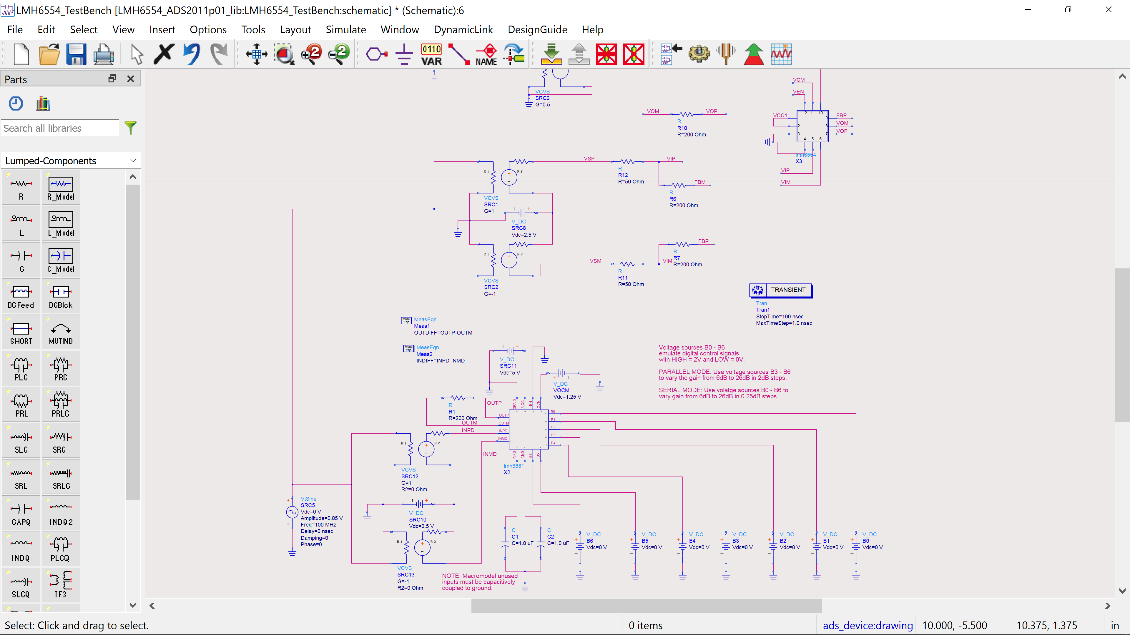
this is the output when both components are connected: https://i.imgur.com/WgvM4eb.png and this is when only the LMH6881: https://i.imgur.com/opR4bYj.png
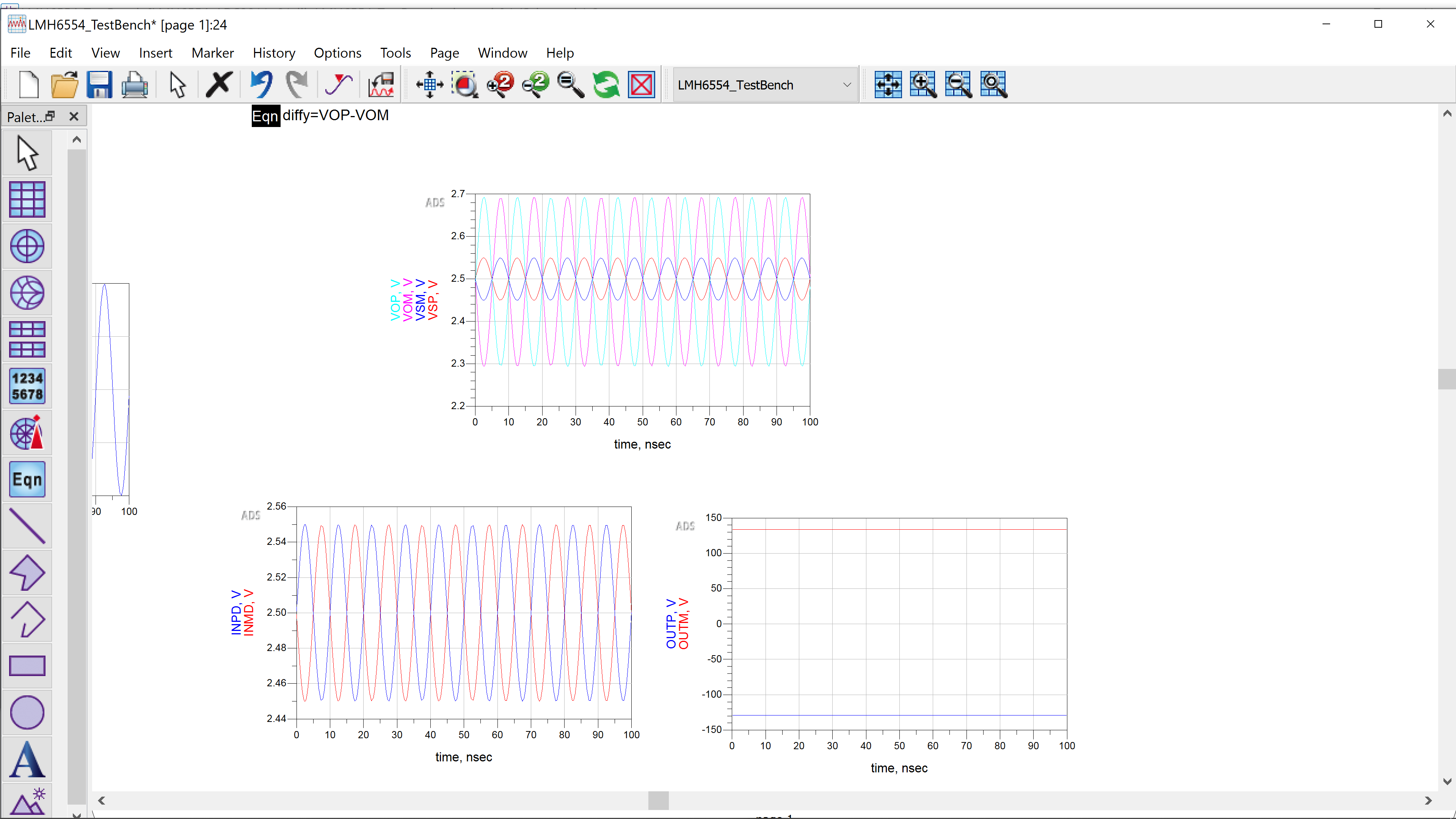
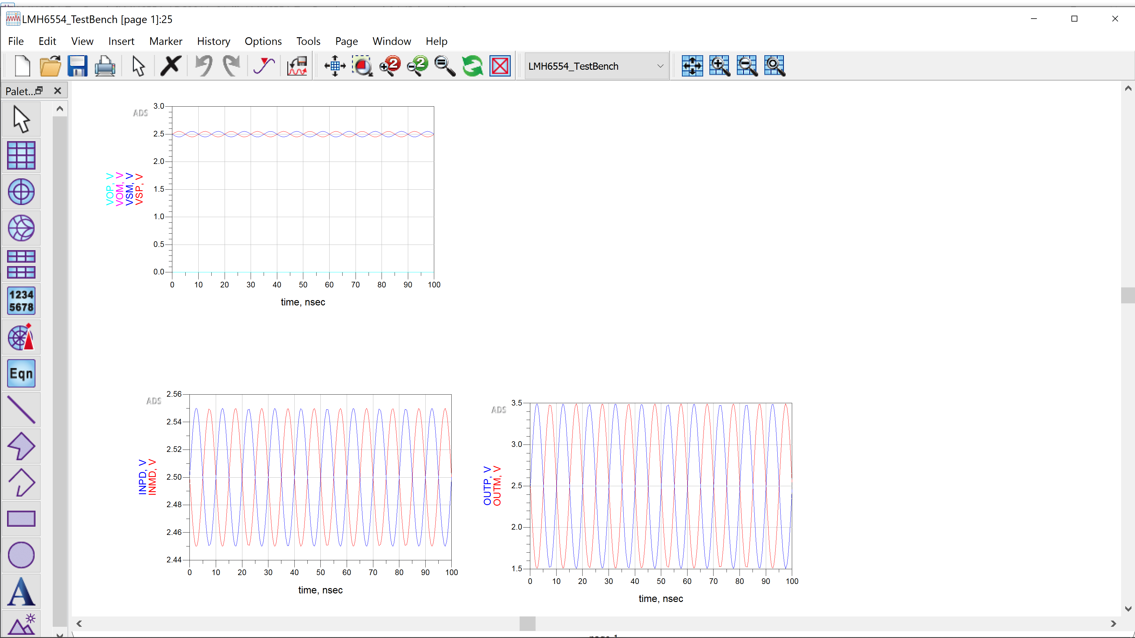
 frank forge
Is that the right model for lmh6881? I get this 24 pin part. https://www.ti.com/lit/ds/symlink/lmh6881.pdf?ts=1621891579255. I don't see why it would not work with the other enabled, sounds like a simulation problem though, check your initial conditions. I also wonder s EN is tied low?
 fiery wolf
What would be the easiest way to get 13.8VDC?
normal drift
That is a common power supply for ham radio. There are many available to purchase.
primal warren
You could use a 9.1V zener in series with a 4.7V zener. It rather depends on what you're starting with and what you need (zener shunt regulation can be fine for low current loads, for example).
fleet terrace
Yeah, 13.8V for which? Like is this soft easygoing amps or RICH CHUNKY CURRENT FLOW needed?
restive fjord
Pyramid power supply is a no-brainer.
Most hams and CB'ers I know have at least one of them.
fleet terrace
Yeah was gonna say there's lots of 20-30A relatively easy to use switchers on the market
restive fjord
Astron linears are probably still favored.
fleet terrace
Yeah, but they're big, heavy, and supposedly kinda pricey outside of the US.
restive fjord
I had a 35 Amp Astron with dual meters.
Once you have one, and then somebody comes along and does 'the same thing' in a lightweight way, you ask yourself how did they do that.
fleet terrace
Not rely on a really old way that requires many kilos of transformers? 🙂
restive fjord
How does 'old' map to 'whatever you are thinking'
;)
You say 'requires' like it's not a good thing.
I like the big iron just fine.
fleet terrace
I think you're reading a lot more into what I was saying that I was actually saying.
restive fjord
The switchers hit the market and succeeded in the market by lowering the price - by lowering shipping costs.
They did not succeed in displacing other factors.
Most big iron products were redesigned with just one goal: lower shipping weight.
So you lose all that thermal mass, in your air conditioner motor.
Lots of burned out motors as a result.
fleet terrace
Gonna have to go with [citation needed] on that one.
restive fjord
;) not without a paycheck.
fleet terrace
Respectfully, I have found none of that to be true.
restive fjord
The person I got it from was reliable.
fleet terrace
And I deal with large DC power systems and HVAC daily
There's a reason telecoms don't run linear rectifiers in their plants any more, and heat generation, inefficiency
(whoops, too quick on the enter key) and physical room needed were big big factors.
restive fjord
I think my <person> meant the consumer market, but I can't check with him. ;)
The remarks were made to me about 15 yrs ago.
He designed motors for a living at the time.
(for a spin-balance machine in automobile tire shops in particular)
Based on the heft of the Pyramid PSU I have here, I'd say it's not a switcher.
fleet terrace
Don't get me wrong, they still do have their place, especially if you need a super low noise power supply.
restive fjord
It's an open question for me.
People my age tend to be biased towards linear PSUs. Hams and CB'ers I mean.
I have nothing specific 'bad' to say about a switcher.
fleet terrace
And for good reason! The early high current switchers were a noise nightmare.
The cheap ones now can also be noise nightmares.
restive fjord
Okay that's probably it .. hash getting into the front end of the receiver.
It's been a while .. I'd forgotten about that.
fleet terrace
The one I have primarily driving my hamshack has a noise offset knob on it of all things, for tweaking the switching freq so it'll move the harmonic off the DX you're trying to work. 😛
restive fjord
This place where I live has an unbelievable amount of radio noise .. just walk around with a handheld AM BC radio receiver. ;)
fleet terrace
Not that I've ever used it, never noticed noise spikes on it to any degree
restive fjord
I have had that happen - had one retasked PC/AT PSU that sat right on channel.
had to QSY when it was on. ;)
The guys out in their mobiles are always saying the LED traffic lights just kill the receiver in the mobile.
FCC has been doing enforcement actions on that, especially billboard signs, iirc.
(somehow that's good press for them, to announce this one peculiar type of case to the media)
 lilac adder
so my antenna of my old deskopt radio snapped. and it doesnt produce a fantastic sound anymore. I soldered a big piece of solid iron Arduino wire to it. but it didnt improve at all. now there are some other problems as well it the best tuning system ive ever seen.an LED and you have to interpolate the right frequency yourself. so I might not be on the best frequency, but am I wrong to assume bigger antenna means better reception?
restive fjord
Depends on the radio band.
For FM broadcast in the USA, that's 88-108 MHz iirc.
The whip antenna on a portable is for FM BC reception.
It's also used on shortwave portables for a similar goal.
AM reception is generally using a loopstick inside the set.
Its a ferrous bar wound with almost a cloth-like wire.
Longwire antennas can be good performers but pick up electrical noise that humans are making in the immediate environment.
 edgy swift
@slender current Flagged Scott because of deep dive videos, but would welcome help from anyone! I JUST want to look for BLE advertisements from Raspberry Pi Python and log them. I watched the deep dive videos, but didn't see generic reads, only specific ones like adafruit_ble and boradcastnet. Ideally I want to find a project or tutorial, but ANY help would be welcome. Project description: I prototyped a device on a feather with BLE, and the prototype my employer got was a MUCH lower power and streamlined process. It advertises every few seconds with ID and two data points. I can see them all in bluetoothctl from the command line, and want the same in python.
Output from connecting to it in bleutoothctl```[NEW] Primary Service
/org/bluez/hci0/dev_E4_78_6E_D9_F6_8D/service000a
00001801-0000-1000-8000-00805f9b34fb
Generic Attribute Profile
[NEW] Primary Service
/org/bluez/hci0/dev_E4_78_6E_D9_F6_8D/service000b
0000fe59-0000-1000-8000-00805f9b34fb
Nordic Semiconductor ASA
[NEW] Characteristic
/org/bluez/hci0/dev_E4_78_6E_D9_F6_8D/service000b/char000c
8ec90003-f315-4f60-9fb8-838830daea50
Vendor specific
[NEW] Descriptor
/org/bluez/hci0/dev_E4_78_6E_D9_F6_8D/service000b/char000c/desc000e
00002902-0000-1000-8000-00805f9b34fb
Client Characteristic Configuration
[NEW] Primary Service
/org/bluez/hci0/dev_E4_78_6E_D9_F6_8D/service000f
3a520100-a687-4366-83fa-bba1f46b3239
Vendor specific
[NEW] Characteristic
/org/bluez/hci0/dev_E4_78_6E_D9_F6_8D/service000f/char0010
3a520101-a687-4366-83fa-bba1f46b3239
Vendor specific
[NEW] Characteristic
/org/bluez/hci0/dev_E4_78_6E_D9_F6_8D/service000f/char0012
3a520102-a687-4366-83fa-bba1f46b3239
Vendor specific
[NEW] Characteristic
/org/bluez/hci0/dev_E4_78_6E_D9_F6_8D/service000f/char0014
3a520103-a687-4366-83fa-bba1f46b3239
Vendor specific
[CHG] Device E4:78:6E:D9:F6:8D UUIDs: 00001800-0000-1000-8000-00805f9b34fb
[CHG] Device E4:78:6E:D9:F6:8D UUIDs: 00001801-0000-1000-8000-00805f9b34fb
[CHG] Device E4:78:6E:D9:F6:8D UUIDs: 0000180f-0000-1000-8000-00805f9b34fb
[CHG] Device E4:78:6E:D9:F6:8D UUIDs: 0000fe59-0000-1000-8000-00805f9b34fb
[CHG] Device E4:78:6E:D9:F6:8D UUIDs: 3a520100-a687-4366-83fa-bba1f46b3239
[CHG] Device E4:78:6E:D9:F6:8D ServicesResolved: yes
[CHG] Device E4:78:6E:D9:F6:8D Name: Senstek
[CHG] Device E4:78:6E:D9:F6:8D Alias: Senstek
CircuitPython would be ideal but the advertising devices are no longer CircuitPython based 😕
edgy swift
Sneaking up on things... looks like broadcastnet will read the advertisements, but does not appear to recognize ManufacturerData key 0xffff. Still looking for hints, but taking this over to help-with-circuitpython.
 jolly coral
Hey radio team
I'm not technical enough to really understand, so I hope people on this forum are 🙂
I have an IOT product in which I used this 433 Receiver module - https://www.amazon.co.uk/iHaosapce-Wire ... B07B9KV8D9
I wanted the same functionality in a HAT board.
I see a bunch of Adafruit receivers -
https://www.adafruit.com/product/3077
https://www.adafruit.com/product/4073
I'm trying to understand which one would replace the receiver I am using.
Any help would be much appreciated.

This is the Adafruit Feather 32u4 Radio (RFM69HCW) 433MHz. We call these RadioFruits, our take on an microcontroller packet radio transceiver with built in USB and battery ...

The latest Raspberry Pi computers come with WiFi and Bluetooth, and now you can add even more radio options with the Adafruit Radio Bonnets! Upgrade your Raspberry Pi with a sub-GHz radio ...
primal warren
Amazon link doesn't work (no surprise there). What functionality are you using? Do you know what chipset the board uses?


 primal warren
Ah, those are very simple receivers, most of them just do OOK (on-off keying) or other simple modulation. They just provide a digital output. The AdaFruit ones you linked to use much more powerful and advanced chips.
Is there a particular reason you want a HAT form factor? It's probably a lot easier to just hook a simple receiver to the appropriate GPIO pins.
jolly coral
We hooked it already, but we already stacked another 2 hats and we'd rather not start welding for the final product. So we were just looking for the cheapest hat that provides the functionality of those simple ones. Even at a higher cost.
primal warren
It is possible that you could use one of the radio modules you linked to in an OOK sort of mode that would be compatible with the simpler modules, but you would presumably need to modify your software to interact with them that way.
jolly coral
Currently using this: https://pypi.org/project/rpi-rf/
PyPI
Sending and receiving 433/315MHz signals with low-cost GPIO RF modules on a Raspberry Pi
 glass burrow
Needing help to set up a SDR (I bought this from Adafruit last week: USB Stick - RTL2832 w/ R820T ) on a Windows 10 OS:
I completed all the steps on the 1st page using SDR# for Windows - https://learn.adafruit.com/getting-started-with-rtl-sdr-and-sdr-sharp/download-and-install-software
**Currently stuck on the 2nd page: Windows' popup box says that the "USB device malfunctioned and is unrecognized" by my computer even though the instructions said that "Windows should automatically install the REALTEK 2832U driver" for the USB SDR receiver dongle/stick & I also installed and ran Zadig but that didn't help since I assume the REALTEK driver was never installed to begin with in the first place- https://learn.adafruit.com/getting-started-with-rtl-sdr-and-sdr-sharp/driver-fix

Adafruit Learning System
A quick-start guide for RTL-SDR under windows and mac os
Adafruit Learning System
A quick-start guide for RTL-SDR under windows and mac os
I don't know what to do to move forward and get this to work... Any advice is much appreciated!
 mint hearth
Does it show in Zadig?
dark nymph
@glass burrow did you get it to work? I'm curious what you see in Device Manager and Zadig as Dimitri mentioned : https://zadig.akeo.ie/downloads/
 upbeat elbow
...and what version of Windows are you trying to install this on? The ability of Windows to auto-setup a device is dependent on the version of Windows. The lastest version is better than older versions (7/8.1).
 hexed flare
anyone have experience getting track data from a bluetooth audio module
restive fjord
@hexed flare Most people who saw your message in the other channel also saw it here.
It's considered best practice to pick just one channel.
 shadow bronze
If anyone has issues (under Windows) using the USB Stick - RTL2832 w/ R820T
Feel free to ping me or tag me. I would be more than happy to help you.
I have installed hundreds of these RTL Dongles.
 cobalt patrol
I got a new toy and made it work with CircuitPython -- ES100 wwvb time signal receiver. https://emergent.unpythonic.net/01624499029
 vestal hatch
hi there, i have an old tv antenna and i wonder if i can use it for transmitting some signal or comunicating with others or anything at all. I know that i may get into trouble with using it incorectly or blocking some channels. Thats why im here to ask.
magic verge
Depends on what band the antenna is tuned. Without an amateur radio license you are restricted to unlicensed bands, and I doubt that a tv antenna would work for that.
 austere schooner
hello, im using an hc05 bluetooth module and an arduino. im trying to control an rc car with the arduino but after testing the bluetooth communication from my phone, the hc05 seems to have high latency. im using this app https://play.google.com/store/apps/details?id=de.kai_morich.serial_bluetooth_terminal&hl=en_US&gl=US to send things to the arduino, but they appear on the serial monitor of the arduino almost 2 seconds later. ive tried swapping out the module with an hc08 and i get the same issue, any idea?

Terminal for serial devices connected with Bluetooth Classic / LE
i even used a custom app made in processing but the lag persists
granite spear
Any chance the lag is coming from the Arduino code side, like your main loop is not checking for received characters very often?
austere schooner
i only send once and wait till i receive it on the arduino end, heres my code : https://pastebin.com/DvCZ0mYG
Pastebin
Pastebin.com is the number one paste tool since 2002. Pastebin is a website where you can store text online for a set period of time.
@granite spear
granite spear
Yeah, that's pretty simple, so not a lot to go wrong there. The HC-05 itself should be reasonably low latency, so I'm not sure where the delay would be coming from.
 hard mulch
Hi! Brand new to playing around with the Circuit Playground Bluefruit (CPB?). Sort of a quick question: Can I set up the CPB to have a custom Bluetooth LE GATT Service (with a custom UUID) with a set of custom R/W characteristics? I'm trying to create a remote control for a board game timer app (via the web bluetooth API)
I'm using CircuitPython. I saw a guide for how to do it in Arduino. (https://learn.adafruit.com/adafruit-circuit-playground-bluefruit/custom-hrm) but I would prefer to do this in CircuitPython. Is that possible?
So far, with CircuitPython, I managed to set up the CPB as a UART service, and can write to the TX characteristic and be notified of updates on the RX characteristic. I guess I could make it work over UART but it seems more ... correct? .... to define my own custom and special made GATT service? Or am I getting this wrong?
Thanks for the help! Hoping to build cool things here! 🙂
 mint knoll
hard mulch
Hi! Brand new to playing around with the Circuit Playground Bluefruit (CPB?). So...
mint knoll
hard mulch
Hi! Brand new to playing around with the Circuit Playground Bluefruit (CPB?). So...
From what I understand, only BLE UART is implemented in CircuitPyton at the moment
https://learn.adafruit.com/circuitpython-nrf52840/overview
Here are some examples of projects:
using Bluefruit LE Connect App to control the CPB: https://learn.adafruit.com/bluetooth-turtle-bot-with-circuitpython-and-crickit/code-with-circuitpython
or two CPBs connecting to each other: https://learn.adafruit.com/color-remote-with-circuit-playground-bluefruit/code-the-color-remote-with-circuitpython
I hope this helps.

Adafruit Learning System
Quickly get started with an Adafruit nRF52840 board using these CircuitPython demos!

Adafruit Learning System
Build your own Bluetooth controlled turtle rover!

Adafruit Learning System
Mix NeoPixels wirelessly with a Bluetooth LE remote control!

Adafruit Learning System
Control NeoPixel colors and animation remotely over Bluetooth with the Circuit Playground Bluefruit!
hard mulch
mint knoll
From what I understand, only BLE UART is implemented in CircuitPyton at the mom...
Ah yes, that helps. Means I can stop bashing my head against this particular brick wall and figure out how to make it all work with UART. 🙂
mint knoll
hard mulch
Ah yes, that helps. Means I can stop bashing my head against this particular bri...
Good luck! 🙂
young cove
hard mulch
Ah yes, that helps. Means I can stop bashing my head against this particular bri...
The capability is there to implement other peripherals, not just UART, including custom ones. For instance we also have HID.
Other examples:https://github.com/adafruit/Adafruit_CircuitPython_BLE_Magic_Light emulates a MagicLight light bulb. https://github.com/adafruit/Adafruit_CircuitPython_BLE_Adafruit is a set of services, that are not UART.
normal drift
Yay -- Finally got my TTN Gateway (Kickstarter Gateway) registered with V3 !! I'm not quite sure why it worked today and not the last time I tried it, but it is up an woking and relaying my V2 devices. Now I can move on to creating some V3 applications.
 hard mulch
young cove
Other examples:<https://github.com/adafruit/Adafruit_CircuitPython_BLE_Magic_Lig...
hard mulch
young cove
Other examples:<https://github.com/adafruit/Adafruit_CircuitPython_BLE_Magic_Lig...
Oh! So, if I get this right, the 'adafruit_ble_adafruit.button_service' is a pre-made service that I can 'install' on the CPB and advertise, and I could then read the button state from a central BT device (like my laptop)? And then I don't have to develop the code to read the button state and write updates of it to the UART service? Have I got that right? Hmmm. If so, that would be a nice alternative. The 'smarts' would have to be written on the Central, but that might be better anyway.
young cove
hard mulch
Oh! So, if I get this right, the 'adafruit_ble_adafruit.button_service' is a pre...
That is correct. We've implemented those services both in Arduino and CircuitPython, and they are used with this app: https://learn.adafruit.com/bluefruit-playground-app. That guide discusses the app, the services, and the code. You don't have to use the app, of course, and we've tried to provide examples for your own central.
 agile merlin
Hey everyone, I just got my first SDR (HackRF One) about a week ago, I was wondering what's the type of signal in the picture called. Looks like a really wide AM (almost 5mhz wide). Thanks!
 primal warren
Could be a spread spectrum signal
hard mulch
Oh, look, it is me again... a few inches closer to my dream of using the Circuit Playground Bluefruit as a remote control for my board game timer. But, I am struggling. Two questions I'd be grateful for help with.
The first is, where is the documentation? Or the API? I'm looking at https://learn.adafruit.com/circuitpython-ble-libraries-on-any-computer/ble-uart-example page and see some example code of how they use the 'adafruit_ble.services.nordic.UARTService, but... where can I see all the available methods I can call? The API? How am I meant to know (apart from looking at examples) that one can call 'uart.readline()' to read data from the UART?
And this isn't just for the nordic UART service but for quite a lot of the CircuitPython / Adafruit world. I'm sure it's there, but after spending a day clicking around the adafruit.com site, I'm starting to get dizzy! 🥴
My second question is about how to use the UART BLE service both to read data from the server AND supply notifications of e.g. button presses.
I've modified the 'ble-uart-example' for eval above. So, I read the line using s = uart.readline(), handle it, then check for button presses, and if I see one, write that to the UART so the central device will know about it.
And it works. Except that the 'uart.readline()' takes a second to complete, and so during that time, no button presses are discovered. I have to press the A button for a full second to be certain that it has been noticed.
Is there a way around this?
OK, third meta-question... Am I asking for help in the right place? Or is there a better place for these kind of questions? For one, it is a bit weird to not be able to include code snippets.
hard mulch
Psst! Me again! I think I figured out how to check the uart TX channel in an unblocking way. "if uart.in_waiting: <read line code>" That way, if there is nothing in the buffer waiting, I quickly move on to the rest of the code like checking button state etc. I found the source code of the adafruit libraries and through that, found the 'in_waiting' property. 🙂
 rare notch
Is there any source code available for the UF2 binary linked from this guide? https://learn.adafruit.com/wireless-image-transfer-with-circuit-playground-bluetooth-and-tft-gizmo/image-transfer-quickstart

Adafruit Learning System
Now you can beam images THROUGH THIN AIR from your mobile device to your Circuit Playground Bluefruit!
Specifically, I'm interested in the "response" part of the protocol which is alluded to here - https://learn.adafruit.com/bluefruit-le-connect/image-transfer#transfer-mode-3044287-16 - "The Transfer Mode setting determines how often the app will require a confirmation response from the Bluefruit hardware before sending more data" ... it is not clear to me if the "response" is automatic as part of the underlying Nordic UART service or if my implementation of the peripheral needs to specifically provide responses in a specific format

Adafruit Learning System
Learn how to use your iOS or Android device to control and communicate with Bluefruit LE.
 slender current
@rare notch are you transferring images or files?
this is my guess for the source: https://github.com/adafruit/Adafruit_nRF52_Arduino/blob/master/libraries/Bluefruit52Lib/examples/Peripheral/image_transfer/image_transfer.ino

GitHub
Adafruit code for the Nordic nRF52 BLE SoC on Arduino - adafruit/Adafruit_nRF52_Arduino
wheat musk
Anyone have experience with the Radiohead library? I'm trying to get it working on an nRF52840-based feather and I'm running into issues when compiling

I've solved most of my other errors but this one is bugging me and I have very limited experience in C++ to figure out what's going wrong.
primal warren
Heh, your anonymizing cut off part of one of the relevant characters
It looks like one namespace error (possibly the compiler doesn't support that language extension), which may or may not affect the next error, which says the variable d was used without declaring it first.
It could be the previous error has something to do with the declaration.
wheat musk
ah yeah that was a d
there were several other errors in my download of the radiohead library, just missed semicolons, etc that I had to fix but those were straightforward
this is the definition of the MeshRouteDiscoveryMessage struct, is that helpful?

on a related note, these are the pins recommended for the nRF52 in the Adafruit example, and then the pin numbers from the datasheet for the Particle Boron that I'm using. I'm less familiar with pin numbers, which ones on the datasheet should I be using to set the radio RST, CS, and INT pins? is it just the D3 type values? So for D3 I'd use 3...

 primal warren
Pin mapping can be tricky
wheat musk
I'll figure it out with an LED + resistor
rare notch
slender current
<@!641475572064583681> are you transferring images or files?
I am making a Go/TinyGo (https://tinygo.org/) library for interacting with the controls in the Bluefruit LE app. Is there also a control for uploading files other than images? That actually would be convenient/useful for me
normal drift
FYI - for anyone with a The Things Network Indoor Gateway (TTIG) - They can now be migrated to the V3 stack. See this guide https://www.thethingsindustries.com/docs/gateways/thethingsindoorgateway/?mc_cid=0fc0a6475d&mc_eid=89c124fce5.
slender current
rare notch
I am making a Go/TinyGo (https://tinygo.org/) library for interacting with the c...
I've been developing https://github.com/adafruit/Adafruit_CircuitPython_BLE_File_Transfer and we're working on some apps and libraries for it
GitHub
Simple (not fast) File Transfer service for BLE. Contribute to adafruit/Adafruit_CircuitPython_BLE_File_Transfer development by creating an account on GitHub.
rare notch
slender current
I've been developing https://github.com/adafruit/Adafruit_CircuitPython_BLE_File...
You must have read my mind... this is great... we just made our first release of filesystem libraries for TinyGo https://github.com/tinygo-org/tinyfs and I've been contemplating what kind of sort of protocol might be useful for getting files onto a filesystem stored on the SPI flash. The protocol spec is nice and simple to follow, I will try implementing a compatible server/client library in Go
GitHub
Embedded filesystems for TinyGo. Currently supports FATfs and LittleFS on microcontrollers with either SDCard or Flash RAM. - tinygo-org/tinyfs
slender current
@rare notch awesome! let me know how it goes. there is a python client library in that repo and I've started a JS one
we have a swift one as well
slender current
normal drift
FYI - for anyone with a The Things Network Indoor Gateway (TTIG) - They can now ...
what is the difference between this and the ttn network?
I just picked up a gateway and don't understand the difference
normal drift
The TTN network just recently provided the instructions for migrating the Indoor Gateway (TTIG) to V3 It was not possible until recently.
slender current
ah, I see there is a community edition
normal drift
They reorganized the whole network, my gateways are on the community edition. Under V2 it was structured differntly.
Do you have the Indoor Gateway?
slender current
yup
normal drift
Was it ever activated on the V2 stack?
slender current
no but I did it on the enterprise stack before realizing there was a community edition
normal drift
ah -- I have no experience on the enterprise stack. Can you move/ redo it -- assuming that is what you want?
slender current
yup, looks like I can
deleted it from the enterprise one and claimed it from the community one
normal drift
Sounds good.
slender current
is there a way to force an update?
normal drift
The migration was a bit painful at times, but now that it is done, it is working very well. I only have one application with 2 devices.
slender current
I was thinking about bridging my ble sensor net stuff to lora
normal drift
for mine, it was unplugged when I claimed it and it came right up when I plugged it.
Do you want to force an update of the firmware? what version does yours have. Mine wa at 2.04 this afternoon,
slender current
mine is 2.0.4 as well
normal drift
I enable auto -update -- is there newer version available?
normal drift
I'm not sure -- but mine is seeing the traffic from my devices so it seems to be OK.
slender current
kk, I don't have any devices 🙂
normal drift
in the V2 console there was an option to upgrade, but I don't see one in V3
Do you see any traffic from your neighborhood 😉 none here....
slender current
I'm not sure how I'd see that
normal drift
look at "live data"
slender current
hrm. just "Update gateway" things
normal drift
 slender current
nice!
normal drift
may not be anyone within range. All my traffic is my own.
slender current
do you collect that data anywhere?
normal drift
no -- There is an API to capture it from TTN, I think.
slender current
I saw an event api
normal drift
I access my sensor data via MQTT then push it to AIO
I used to use an "integration" to IFTTT, but I was not able to get it working in V3. so I switched to MQTT
slender current
interesting
normal drift
I run a program locally to monitor the MQTT subscription and when it updates, it send the data to my AIO feed.
slender current
ah, ok
https://meshtastic.org/ looks pretty neat
Description will go into a meta tag in
normal drift
Yes -- I have a few meshtastic devices. Just need time to play with them
T-Beam - Meshtastic
They worked well "out of the box" but I need to dig deeper into them.
slender current
do you know if multiple phones can connect to one meshtastic?
normal drift
hmm, not sure.
slender current
I was thinking that'd be cool for multiple groups of people off the grid
normal drift
yes - it would. It's been awhile since i tried them. Need to dust off the cobwebs....
I like playing with the rf stuff. Brings me back to my ham radio days.... the nrf24l01 are also fun.
I have too many toys 😉
slender current
ya, I have too many things I want to do too
I thought it'd be nice to host a things gateway though
normal drift
I think so too, I keep hoping to see someone else use it, but it's unlikely here. More likely for you! Still , doing my part to expand the grid.
slender current
I'll keep an eye on mine to see
normal drift
I have two gateways and I hope to find someone else in town that will let me install one
slender current
I turned on the verbose log
normal drift
I have to admit, I was so frustrated by the V3 migration, i almost gave up and turned them off, but it got much better recently and I was able to migrate both gateways and my application and devices fairly easily. I have one of the older "kickstarter" gateways. It was a very different process.
Now it seems easy.
slender current
🙂 it wasn't too bad once I realized where I needed to be
normal drift
The rollout was very confused, in my opinion, but improved with time. I just did not understand what they were doing and the difference between the enterprise and community edition. I have little interest in the enterprise side
slender current
ya, me too
I didn't realize I was looking for "console"
and the docs were hosted on the enterprise site
normal drift
It would be really nice to bridge BLE to LoRA... small scale to large...
slender current
ya, similar to the messaging idea
a bunch of close nodes talking over a distance
normal drift
lots of applications for getting beyond WiFi range.
Bed time for me -- have a good night!
slender current
thanks! good night!
slender current
@normal drift I have a 22 next to my gateway's up arrow
 rare notch
@slender current I'm sorry if this is a basic question but I am not very familiar with circuitpython ... I'm trying run the example from https://github.com/adafruit/Adafruit_CircuitPython_BLE_File_Transfer/blob/main/examples/ble_file_transfer_stub_server.py so I flashed the latest stable CP onto a circuit playground bluefruit ... my filesystem was empty so I grabbed a bunch of files/folder from the library bundle that sounded like they might be necessary copied them to the lib folder, and then copied the example code into code.py in the root folder of the device. When I update the code.py, the serial output says
code.py output:
Traceback (most recent call last):
  File "code.py", line 13, in <module>
ImportError: no module named 'adafruit_ble_creation'
I can't find adafruit_ble_creation in the library bundle... am I barking up the wrong tree with the procedure I used above?
slender current
I may have missed it

GitHub
Library for using Creation IDs when discovering BLE devices - adafruit/Adafruit_CircuitPython_BLE_Creation
 runic dune
@slender current Hi, I'm looking for the best way to do an NTP time sync with the Feather S2, I came across the adafruit_ntp circuitpython library but noticed it was incompatible with the native wifi radio object and started reading these open issues: https://github.com/adafruit/circuitpython/issues/3321 https://github.com/adafruit/Adafruit_CircuitPython_NTP/issues/16
Wondering what the status of these are, and if I should use a work-around like mentioned in issue 3321: https://github.com/adafruit/circuitpython/issues/3321#issuecomment-712515657
runic dune
Hmm while it explicitly says that it's not a replacement for NTP, I think this adafruit IO API could work well enough for me: https://io.adafruit.com/services/time
slender current
@runic dune I think there is a version of NTP that does use a standard socket api. I didn't have much issue myself because I realized the weather API has time too. IO handles timezones well too
 drifting oasis
normal drift
I have to admit, I was so frustrated by the V3 migration, i almost gave up and t...
drifting oasis
normal drift
I have to admit, I was so frustrated by the V3 migration, i almost gave up and t...
Hi Do you have any suggestions for someone trying to migrate to V3 ?
i have the TTN kickstarter gateway that appears to have migrated ok to V3 and it shows as connected in V3 Gateway console.
But i do not see any traffic and do not see my end device reporting in the application console ... YET i also still have another V2 gateway that is properly seeing the end device and sending the packets to the V3 application console.
I have posted about this on the TTN forum, but so far no helpful responses.
Since you have yours working, i thought maybe you have some suggestions for debugging.
NOTE1 before migration of end device and Gateway, all was working fine in V2 consoles.
Now, all is working fine with going thru the gateway still configured for V2, but nothing at all appears to go thru V3 gateway.
on the TTN forum i have posted a section of the uart serial console log, and it appears that gateway is connected and is hearing the lora transmissions from the end device and transfering that to the V3 servers, BUT nothing ever appears in the V3 console from this gateway.
i must sill have something misconfigured, but i cannot figure out what that is.
if you have any ideas or suggestions, please let me know
normal drift
@drifting oasis Once I got the KickStarter Gateway to connect to V3 following this guide https://www.thethingsindustries.com/docs/gateways/thethingskickstartergateway/ , it immediately started seeing my V2 devices and was relaying their packets, I have since revised my devices to use V3 (really just had to recompile them with the latest arduino LMIC library) and I then created an application for them in the V3 console. That all went very smoothly. I don't have any particular suggestions. The first time I tried to connect the Kickstarter gateway to TTN, I could not get it to work and I eventually put it aside. When I tried again, a few weeks later it worked easily. I don't know what changed. I wish I had some advice to offer.
vocal veldt
@drifting oasis @normal drift The official TTN docu for migrating is here: https://www.thethingsnetwork.org/docs/the-things-stack/migrate-to-v3/

The Things Network
We are building a global open free crowdsourced long range low power IoT data network
drifting oasis
normal drift
<@!341402837840035841> Once I got the KickStarter Gateway to connect to V3 follo...
@vocal veldt @normal drift thanks for the comments and links. I had been using those docs and links from the beginning, but found at some points that those docs were lacking detailed info, when things did not work as expected 🙂 In any case ... i spent the afternoon using the brute force method and deleted the V3 gateway and added new gateway over and over again a number of times, each time using a new gatewayID so as not to have confict with previous ID's. Then i checked and double checked ID's and keys and everything else associated with registering a gateway in V3, and eventually, the gateway connected and the end device packets started showing up in V3 Gateway and Application V3 console. So now packets that arrive come from both the migrated V3 gateway and the other V2 gateway. So now all appears to work as it should.
I do not look forward to migrating the other gateway as it is a multitech gateway and more complicated to configure 🙂
Thanks for your responses.
vocal veldt
@drifting oasis The Things Network NYC group operate a few Multitech gateways around NYC, might be a good idea to check their slack channel
they're helpful folks
 blissful pivot
Hey there, not sure if this is okay to ask here since its not a adafruit device or circuitpython, rather Pycom and micropython.
Im trying to figure out BLE pairing with Pycom GPy/WiPy/LoPy boards. trying the example from the Pycom docs im able to send and receive data, but the other device has to be able to do so while un-paired, which many cant. Can anyone point me in the correct direction on how to get BLE pairing to work?
here's the docs im looking at: https://docs.pycom.io/firmwareapi/pycom/network/bluetooth/
 tiny minnow
I pointed @blissful pivot here from the python discord on the thought that there's enough work on BLE going on here right now that someone might have a direction to point us
slender current
you are welcome to ask but there may not be anyone who can help
the micropython forum might be a better spot
tiny minnow
Do you have any links to things that helped you with the BLE workflow design?
There's the bluetooth and ble spec, which are.. not as straight forward as I expected them to be, but after so many hundreds of pages that's probably my issue, not the specs issue, but was there anything else?
slender current
this has a good overview of terms: https://learn.adafruit.com/circuitpython-nrf52840/bluetooth-basics
Adafruit Learning System
Quickly get started with an Adafruit nRF52840 board using these CircuitPython demos!
tiny minnow
Thank you!
blissful pivot
@slender current @tiny minnow well it seems i wont need any help after all, as the pycom board do not support pairing or bonding at all.
https://forum.pycom.io/post/4884

Forum
@ghilinta.daniel Well the Pycom boards don't accept pairing requests yet, but you don't need to pair to have your Android application communicate with it over BLE. Simple set your desired BLE services/characteristics according to the example I linked bel...
which, im not going to lie, sucks and is a good argument against pycom being used in the company
tiny minnow
oof, no full bonding is a major drawback--needing to re-enter scanning and pairing each time you want to communicate is a solution, but a messy one. That's a bummer
blissful pivot
tiny minnow
oof, no full bonding is a major drawback--needing to re-enter scanning and pairi...
its not just bonding thats missing. pairing too. so i can only send data un-paired which is possible but only with specific apps on a phone and not at all on windows
tiny minnow
Ah, this is a distinction of terminology I'm just not great with yet because I haven't played much with bluetooth. And I keep nearly buying a bluefruit to play around and learn more. Maybe later this evening I'll cave. Nothing wrong with just one more board after all
 daring sequoia
Should light be in this channel?
 half plover
Sure, light is a valid transmission source
🙂
You can modulate light similarly to RF
granite spear
Yep! I used to work in long-distance laser comms. 😁
primal warren
I like the terahertz band
 restive fjord
Anyone got issues with software radio or radio chips in Canada ?
Like delivery or stuff like this? Should I get advanced ham license to be sure ?
I already can't buy lithium batteries from adafruit because of being in canada so I'd like to know
primal warren
The 433MHz and 915MHz industrial, scientific, and medical (ISM) bands should be usable at low power without a license in Canada. You should be able to buy AdaFruit merchandise from a Canadian reseller such as digikey.ca
However, getting a ham license does get you access to more bands, and is generally useful and worth doing. If you're technically minded, it shouldn't be too difficult.
 frank lagoon
Hello, Adafruit sell LoRa and RFM69 boards like the: https://www.adafruit.com/product/3070
The photo on the product page shows a nice black antenna connected to the board via a uFL-to-SMA cable, and while I can find the solder-on edge launch SMA connectors (item 1865) I likewise can't seem to locate the solder-on uFL connector shown in the photo, so buying the antenna kit leaves me with a vital part missing unless I want to attach the antenna directly to the board. There is the uFL SMT connector (item 1661) but given it's an SMT part I'm guessing it isn't able to bridge the solder pads on the RFM69 board. As the RFM69 board doesn't have any mounting holes I'd want to panel-mount the antenna and minimise the stresses on the board itself.
Any idea where I can find that solder-on uFL connector shown in the photo? Thank you!

 normal drift
@frank lagoon The 1661 part can be used -- it was not easy to get it to bridge the pads, but I was able to do it on this featherwing
 frank lagoon
normal drift
frank lagoon
normal drift
Thanks @normal drift glad to know the SMT part can work. I'm reasonably good with a soldering iron (been using it since the 70s) so I'm game to try. I tend to prefer avoiding using solder bridges when possible as they're not particularly strong (especially where an external cable is going to be attached), but if there's nothing else available, well, beggars can't be choosers...
normal drift
It was not my finest soldering, but it seems to work. It's been a few years since I did that one. I was not eager to do it again!
frank lagoon
Well, so long as it works I'd say you were successful!
normal drift
there is a guide to installing it here https://learn.adafruit.com/radio-featherwing/assembly#ufl-connector-2057641-3>

looks a lot easier than it was!
frank lagoon
Ah, thanks. I'm considering just buying the RFM69 board, not the full Feather, but same idea. I'm thinking of buying a pair of them to try out long-distance slow-communications between a Pi home base and a remote robot, Mars Rover style.
Oh, yes, I see in the docs you suggested the whole solder trick. I wonder how many people manage that on the first go.
normal drift
For "long-distance" have you looked at the RFM9x instead of the RFM69?
frank lagoon
Yes, I don't need that 2km thing, as 500m would be fine. I don't want my robot actually out of sight really (it might get nicked). I am under the impression that the RFM69 rather than the LoRa is a bit easier to use and you (apparently) get packet-resend. All new to me.
The RFM96 is LoRa to my understanding. And a bit harder to use...
normal drift
500m with the rfm69 may not be trivial. I use both and don't really find the 9x any more difficult. -- it's al hidden in the library - if you use the Radiohead (arduino) library then its just a case of selecting the driver. Both can use the "reliable datagram" mode so they do "acks" and retries.
If you are using CircuitPython, the rfm69 M0 or rfm9x M0 boards are very limited in both RAM and Flash. The featherwings on an M4 are a much better approach for Circuitpython.
frank lagoon
Yeah, I'm aware that it's really hit and miss, but that's kinda the challenge. I was planning on trying this actually on a Pi, not a microcontroller. If that doesn't work I'll move it over to either an Itsy Bitsy RP2040 or a TinyPICO (ESP32).
...though it occurs to me that if we're talking CircuitPython rather than MicroPython I've actually got a FeatherS2 (ESP32) which does CP.
normal drift
The featherwings work well on the umfeathers2 -- The "sleep" mode in CP is nice to save power. They will also work well on the Pi. If you want an OLED dispaly on it look at the "bonnet" < https://www.adafruit.com/product/4073> not sure if you want 433 or 915MHz
 cobalt lake
I would get the RFM9x instead of the RFM69
I have some and it is not easy to get the advertised range unless you have perfect conditions
frank lagoon
normal drift
The featherwings work well on the umfeathers2 -- The "sleep" mode in CP is nice...
This is going on a robot whose GPIO is already overflowing so I was thinking the smaller board was welcome.
frank lagoon
cobalt lake
I would get the RFM9x instead of the RFM69
I'm not actually that concerned with range, more with the idea that the RFM69 might be a bit easier to use. If I get 100m or 200m or 500m it's all really the same. I'd be afraid to be so far away from a thousand dollar robot that I couldn't see it. I.e., this is more an experiment in remote tele-robotics with deliberately shaky coms.
normal drift
It sounds like fun. Good luck with it.
frank lagoon
Thanks, it does sound kinda fun, me pretending to be NASA Houston.
cobalt lake
frank lagoon
I'm not actually that concerned with range, more with the idea that the RFM69 mi...
Good luck with the project, the RFM radios are really cool and lots of fun to play with
frank lagoon
cobalt lake
Good luck with the project, the RFM radios are really cool and lots of fun to pl...
While my workflow is basically to ssh in to my robot's Pi, do my development and testing, push to github, etc. it seems a bit like cheating to actually run the robot over WiFi. It's meant to be semi-autonomous, but I want to be able to direct it remotely, in the same way (obviously very roughly speaking) that NASA was doing with the Sojourner robot. I once saw it on a desk at NASA HQ and I've wanted my own ever since... 😁
cobalt lake
frank lagoon
While my workflow is basically to ssh in to my robot's Pi, do my development and...
Let me know if you develop a good system for remote code upload over the radios
frank lagoon
cobalt lake
Let me know if you develop a good system for remote code upload over the radios
Sure, will do. I'll be chatting about it over on Personal Robotics. If you're not on there let me know and I can send an invite.
I'm currently digging around on all the possible boards now from Adafruit and wondering if maybe just getting one of the Feather RadioFruits is easier, basically have it do all the work of transceiving, then have the Pi talk to it over UART, I2C, etc. I've noted that the RFM69 board talks to the Pi over SPI but my robots are already using one of the SPI buses for a TFT display, not sure (yet) if I can use the other SPI (I think there are two) for the RFM. But it's getting late here, we've got 100km/hr winds buffeting my house, and I probably need to go to bed...
normal drift
You can use the same SPI bus -- just use a different CS pin.
frank lagoon
So CS0 for the TFT display and CS1 for the RFM?
normal drift
Or any GPIO pin for CS
frank lagoon
Ah, good. Okay, so long as the non-Feather board isn't a complete hassle using with a Pi I'd probably go with the Pi, as otherwise I've got Yet Another Indirection having to communicate between the Pi and the microcontroller rather than the Pi and the RFM.
cobalt lake
frank lagoon
Sure, will do. I'll be chatting about it over on Personal Robotics. If you're no...
I'm already on the server
normal drift
It "should" be fine.... of course, "your mileage may vary" 😉
frank lagoon
Oh, I am plenty aware that there's no guarantees in life... 😛
But it does sound like fun.
frank lagoon
cobalt lake
I'm already on the server
You may already be aware of my kros-core robot OS project on github then. The RFM part would sit on top of that, probably be a project in its own right (unless I'm lazy as normal and just munge everything together in one project).
normal drift
I looked at it a few months ago, but will take another look.
cobalt lake
frank lagoon
You may already be aware of my `kros-core` robot OS project on github then. The ...
I remember having a look over that a while back
frank lagoon
cobalt lake
I remember having a look over that a while back
Well, it's still making me crazy months later.
I've just managed to get the motor controls hooked up, but it's still a bit drunken. Yesterday I took my old "Integrated Front Sensor" class and shoved it into kros as a Publisher subclass, so now the bumpers and analog IRs send messages onto the message bus. I have no idea at this point why I've made such a monster.
cobalt lake
Good luck with cleaning up that mess
frank lagoon
I never do anything the easy way it seems.
cobalt lake
I just reinstalled my desktop with debian 11 but once I setup my development environment again I will try to get the i2c slave working on the rp2040 which might help with your project.
Got a couple of different ideas on how to implement it, one of which is fairly complex and but should offer very good performance and low latency.
frank lagoon
cobalt lake
I just reinstalled my desktop with debian 11 but once I setup my development env...
I did realise that the pigpio project does have an I2C slave support for Arduino-style devices if I'm willing to dump Python on the slave/client but I really at this point don't want to go backwards. If anyone can get a nice master-slave thing going in I2C entirely over some flavour of Python, on some microcontroller, that would be a huge win.
cobalt lake
frank lagoon
I did realise that the pigpio project does have an I2C slave support for Arduino...
Using python everywhere makes things very easy compared to having to switch to c or c++. Don't count on my plan working any time soon or at all as I realised it is going to take quite a bit of code written in c to make it work correctly.
frank lagoon
cobalt lake
Using python everywhere makes things very easy compared to having to switch to c...
Somebody I was chatting with was talking about using the PIO, was that you?
cobalt lake
frank lagoon
Somebody I was chatting with was talking about using the PIO, was that you?
It was
frank lagoon
Ah
cobalt lake
Although my plan has changed a bit since then
frank lagoon
One of these days I'll dig into the RP2040 a bit. I've got several Picos and an Itsy Bitsy, and it seems a capable chip. Too much stuff too little time, not enough sleep!
 summer venture
this is a really stupid question, i know, but when working with radio what do you use as ground?
i'm taking about battery powered projects here
because to the best of my knowledge radio works by turning electromagnetic waves in the air into voltages on a wire
and all voltages need a reference to be read
so what do i use as my reference? and why does it work?
granite spear
It's not a particularly stupid question, but the answer is basically "it doesn't matter". The radio wave is oscillating at MHz or GHz frequencies, so as long as your reference voltage isn't changing from nanosecond to nanosecond like that, you can still pick up the radio signal from the relative change in the voltage of the antenna.
primal warren
For lower frequency radio (such as the AM band), you can use a loop antenna (with or without something like ferrite to concentrate the magnetic field), which is its own reference. For higher frequencies, you can either use a dipole, or a monopole with a counterpoise. But in all cases, the wave induces current/voltage in a conductor, and the goal is to harness that.
 worn glacier
Did someone try using a SIM800L with a Raspberry Pi? From what I read, it should have GPRS, SMS, FM radio and is capable of doing calls. I've found some guides, but would like to know if someone was successful using it with a Raspberry Pi, and which of its functions were used
primal warren
I've used the somewhat related SIM808, but with a different CPU and I haven't tried FM. Since it's controlled with ordinary asynchronous serial commands, I don't see why it wouldn't work (you can hack up the FONA library to do most of the work like I did).
I even designed it into a custom board

Ah, I see your edit: I was actually using the GPS function 🙂
worn glacier
It's going though a process of gradually freeing itself from restraints: first it was the 30 cm of the USB cable, then Bluetooth range, now Wi-Fi range, next is going to be where 2G networks exist
Next will also require soldering and possibly a custom PCB, both new to me. SMS alone won't work what I have currently (as I would need to have something else to receive), so, for the immediate practical usage, GPRS would be the best approach
2G is a bit of a gamble, but it's more likely 3G will be disabled first
primal warren
I'm currently eyeing a SIM7600NA for 4G support
The SIM7600A has 4G support with less band coverage, but also includes 2G and 3G.
alpine bone
What are the requirements for using the bluefruit app? I'm looking to add Bluetooth control to a project, but want a cheap board to do the job.
 swift bane
Hi, I was wondering, I have some remote controlled sockets -> Extel 763216 (trash company with 0 client support), you can control the sockets using a remote control which has 4 channels (on/off) to pair the sockets but the remote control for some reason is not working anymore (the socket pairs but it doesn't turn off or on), I'm not sure about the frequency and I'm totally unexperienced with those stuff, Is there any way to connect to them using something else?
final edge
alpine bone
What are the requirements for using the bluefruit app? I'm looking to add Blueto...
Just having a BLE device you can write firmware for, so like a nRF52 or ESP32 board will let you. For example https://www.adafruit.com/product/3406
The Adafruit Feather nRF52 Bluefruit is another easy-to-use all-in-one Bluetooth Low Energy board, with a native-Bluetooth chip, the nRF52832! It's our take on an ...
final edge
swift bane
Hi, I was wondering, I have some remote controlled sockets -> Extel 763216 (tras...
Interesting, are you looking to make your own remote replacement, or interact with them over a network using your phone or something?
alpine bone
final edge
Just having a BLE device you can write firmware for, so like a nRF52 or ESP32 bo...
But would just any Bluetooth chip work?
final edge
alpine bone
But would just any Bluetooth chip work?
Well if you want to use the bluefruit app, while any BLE microcontroller can technically talk to the app, it is a lot less work if you use a platform with a already supported BLEAdafruitService implementation like the ESP32 or nRF52. Both of which you can get really inexpensive boards for
alpine bone
Alright, thank you!
 slender finch
I'm looking to build a UHF RFID read system, but I'm a little out of my depth here, does the antenna and the reader have to be UHF, does just one? is it possible for me to make a reader myself using a microcontroller, or is there special circuitry that goes into it
I guess I'm just looking for solid background knowledge
primal warren
The reader and the target both need to be the same frequency, so a UHF reader would need a UHF target (and they'd both need UHF antennæ)
There is special circuitry involved: you could build it yourself, but UHF circuitry requires some advanced techniques.
slender finch
primal warren
There is special circuitry involved: you could build it yourself, but UHF circu...
ok thank you, do you have any recommendations for a uhf reader ic?
primal warren
For the 900MHz band, the only one I'm familiar with is the Thingmagic Nano module.
slender finch
alright i'll look into it, thank you
also quick question, do you know how well uhf handles multiple tags passing by in quick succession or even simultaniously?
primal warren
The Thingmagic one is a "simultaneous" reader and can read a bunch of stuff at once.
slender finch
primal warren
The Thingmagic one is a "simultaneous" reader and can read a bunch of stuff at o...
perfect thank you
swift bane
final edge
Interesting, are you looking to make your own remote replacement, or interact wi...
I was looking is there any way to create a remote replacement
primal warren
Probably. Most of those cheap things use simple encoding, so all you need is a transmitter of the right frequency and either a matching coding chip or a microcontroller programmed to emulate it. I'm glossing over a lot of detail, as I don't know enough about the particulars of your device to be specific.
magic verge
Any pointers for SSTV on an M4 board?
 somber pagoda
Can a RP2040 feathering be used in place of a a M0 to communicate with a 96 lora featherwing using Circuitpython?
half plover
somber pagoda
Can a RP2040 feathering be used in place of a a M0 to communicate with a 96 lora...
Which specific feather wing?
I’d be inclined to say yes
somber pagoda
I picked up 2 3229 RFM69HWC and 2 4884 Feater RP2040.
I have it working in arduino using ESP32 but I wanted to used the Rp2040 but in CP. To make it easier on me
half plover
Looks like it communicates over SPI so in theory it should port right over with CircuitPython
I think it would be a matter if there is a circuitpython library for it
And there is so i will preliminarily say yea, it should work fine
somber pagoda
I am hoping j can get Adafruit 1733 Wind Speed and wind direction, both put out a 0 to 2 volt output
I like this Lora board and easy to configure but it's fighting me with the RP2040.
somber pagoda
Arduino so figured to go with CP but wasn't sure of the lora libraries.
half plover
That learn guide should have what you need to use it in circuitpython so hopefully that will be easier
somber pagoda
I'll take a look ... funny it didn't show up on my searches. Thanks
Oh man I did read this but I didn't think it would apply towards a RP2040. I'll give it a try tomorrow.
half plover
👍🏻
restive fjord
@somber pagoda Might ping @normal drift since jerry is versed in radio data link stuff.
normal drift
@somber pagoda I have just verified that an rfm9x featherwing works normally with a feather RP2040.
somber pagoda
normal drift
<@!579810877864411136> I have just verified that an rfm9x featherwing works nor...
@normal drift I am hoping you're saying it works well in CP
normal drift
Yes, it does.
 covert schooner
Hi, new to RF/BLE/WiFi communication devices, I am trying to find someone to help me pick out an XBee model best suited for a project. Sub 300ft point to point, using one as a controller and the other as reviving for a robot.
somber pagoda
@normal drift I want to thank you for your support. I have my 2 RP2040's talking to each other over LoRa RFM69 library running CircuitPython. I had to do some timing tweaks and added some code at the end so it would send then receive back and forth in the sample code. once in a blue moon I get a unicode error so may just wrap a try statement there.
normal drift
@somber pagoda great! Glad it is working. I often see the Unicode errors due to noise signals. Try/except does help ignore them.
somber pagoda
@jerryn true but it does keep the code running and just spits out an error message in the REPL. This is great
 sharp dagger
anyone here familiar with pybluez?
i have the following snippet which I got mostly from here: https://people.csail.mit.edu/albert/bluez-intro/x290.html that i've tweaked a little
import bluetooth

server_sock = bluetooth.BluetoothSocket(bluetooth.L2CAP)

port = 0x1001
server_sock.bind(("", port))
server_sock.listen(1)

bluetooth.advertise_service(
  server_sock,
  "Service Name",
  bluetooth.AV_REMOTE_CLASS,
  bluetooth.AV_REMOTE_PROFILE)

client_sock, address = server_sock.accept()

client_sock.close()
server_sock.close()
i'm unsure as to whether bluetooth.AV_REMOTE_CLASS and bluetooth.AV_REMOTE_PROFILE are correct for my work (i'm attempting to use an AVCRP profile to get album art from my phone)
sharp dagger
feel free to @ me
 ocean kayak
feel free to spew code in the open too, I don't think I've seen a bluetooth server in python code before :-)
sharp dagger
i'll be making it open source if i ever manage to make it work haha
primal warren
@sharp dagger I've never used pybluez, but I see that AV_REMOTE_PROFILE includes AV_REMOTE_CLASS https://github.com/pybluez/pybluez/blob/896c11ac730e026306b2dc5bb5fbdf92ab9dd6a7/bluetooth/btcommon.py#L88
sharp dagger
yeah that's where I got the profiles and classes from. I watched a few videos on characteristics, services, and profiles and I'm still a little shaky, but I'm getting there
 steep herald
@somber pagoda which radio library are you using that worked with the raspberry 2040?
I have 2 RFM69 (not lora) 915mhz working with the Adafruit fork of the Radiohead library. I get a rssi from the examples of -31 when the 2 radios are side by side. They both have a ufl connector soldered on and the plastic antennas. Should my connection strength be higher? Did I solder the connector poorly? How would I verify that?
 fast robin
I have a couple Adafruit Feather M0 RFM95 's working in the TX/RX mode at 915 MHz following https://learn.adafruit.com/adafruit-feather-m0-radio-with-lora-radio-module/using-the-rfm-9x-radio This uses the latest RadioHead libraries in the Arduino IDE. I am having problems connecting to the Helium Network following https://docs.helium.com/use-the-network/devices/development/adafruit/adafruit-feather-m0-rfm95/adafruitio/. The problem could be that the guide is for Helium Console V1 which has been superseded by V2. Does anyone have experience here? Or would it be easier and better to switch to another environment such as Adafruit MQTT using the Helium Network? Or would Circuit Python with Adafruit IO be better? I am just looking for something that works over the Internet and am open to any environment, but I need some gateway which is now the Helium Network. Another option would be to use a The Things Network gateway (TTN), but there seem to be several variations which could be difficult to sort out.

Adafruit Learning System
Send your message really really far and wide
Adafruit IO Guide with Adafruit Feather M0 RFM95
fast robin
Here is a presentation on using Adafruit IO integrations in Helium Network. Does anyone know if there is any coordination between Adafruit IO and Helium technical support? https://www.youtube.com/watch?v=4GsavGvIr7M

In this episode, learn from Helium engineer Kent Williams on how to connect a simple sensor with the Adafruit Feather M0 with RFM95 LoRa board, program it with an example sketch, and configure the Adafruit IO integration on Console. You’ll see data streaming on Adafruit IO's dashboard in no time!
Connect with Helium:
Site: https://helium.com
Tw...
slender current
@fast robin no, we didn't coordinate with them. they added support on their own
vocal veldt
fast robin
Here is a presentation on using Adafruit IO integrations in Helium Network. Doe...
Please contact Helium for any technical support regarding this integration. Thanks!
steep herald
What are RSSI values people get with RFM69 radios using external antennas in close proximity. I have -31 and that seems low.
primal warren
Hmmm, mine are just wire antennæ but I don't remember what sort of RSSI values I got
 steep herald
I thought I remember better with just wire. Wondering if I attached the connector wrong/badly, but not sure how to troubleshoot that.
restive fjord
magic verge
Any pointers for SSTV on an M4 board?
Audio decode, video encode?
Played around with the technology when I found it in Portal. What are you trying to achieve with ARM M4?
restive fjord
Trying to decode these images from audio, possibly could use an external I2S ADC IC and send data to the MCU, the MCU if it is powerful enough can decode the I2S audio into a image.
 sonic coral
Does anyone know why simple lora transmitters are limited to 100 mW of transmission power? But, there are Xbee modules that transmit on 915 MHz with much more power, in some cases 1 watt?
Is it legal to transmit with higher power in the 900 MHz band if you are HAM licensed?
west perch
Depends on where you are
sonic coral
west perch
Depends on where you are
Do you have a map? Or a link to those regulations?
There wasn't anything in the technician HAM manual so I just don't know the info
west perch
I don't know if there's a global map? If you're in the US I'm pretty sure just FCC rules apply across the board
sonic coral
west perch
I don't know if there's a global map? If you're in the US I'm pretty sure just F...
Which rules? I know for licensed HAM operators they can transmit up to 1500 watts on most* frequencies.
But, I'm not sure if there is an exception for LoRa
west perch
I think if you have your license, you can use any transmitter? but I'm not a HAM and my knowledge is spotty
sonic coral
I have considered picking one of the frequencies designated for data that way I could use like a 1 or 2 watt transmitter
Although that would require a custom transmitter and receiver solution.
west perch
I found a conversation about HAM power limits in the 900MHz range, but I'm a bit too tired to parse it... need to get to bed! https://community.ui.com/questions/900mhz-HAM-power-limits/19a99288-cfe5-424a-a2a6-e9b876d7276d
sonic coral
All good, thank you for all your help tonight! Good night!
west perch
No problem, night!
magic verge
restive fjord
Audio decode, video encode?
M4 SSTV -- I want to transfer an image from pybadge to my PC (mmsstv).
 grand breach
somber pagoda
Can a RP2040 feathering be used in place of a a M0 to communicate with a 96 lora...
grand breach
somber pagoda
Can a RP2040 feathering be used in place of a a M0 to communicate with a 96 lora...
Yes...I've done it. Even tho the Learn page doesn't describe it. Solder the three jumpers like they show on the Learn Page: IRQ => B, CS => E & RST => D
grand breach
Recently, the FCC has issued new requirements for hams to self regulate their RF exposure. 1500 Watts at 900 mHz could hurt someone...or release the magic smoke from the hardware.
I'd like to use these two RFM95 Featherwings to talk back and forth on a 430 mHz frequency here in the US. I'm a licensed ham. I'm looking for tips on how I can ID with my callsign every 10 mins. as the Part 97 rules require. Suggestions?
 tardy heron
I forget what the rules were around the older packet radio modes, been ages since I did anything there. However, I want to say for the digital modes, the station call was transmitted in every packet. There's nothing saying you can't ID the station more often.
https://www.qsl.net/yb0emj/packet.html
One advantage of AX.25 is that every packet sent contains the sender's and recipient's amateur radio callsign, thus providing station identification with every transmission.
If you're using a standard protocol, just put your call somewhere in the packet, but discard it when you process the rest of the data.
grand breach
I have been doing that in my initial testing. I'm not sure that;s OK though. LoRa is end-to-end encrypted. And the LoRa spread spectrum modulation scheme is unusual on the ham bands. I was hoping there was a way to add my call to the header portion, outside the encryption.
tardy heron
I know there's been some changes to the rules with regards to digital modes, but I thought encryption was still verboten.
grand breach
Encryption to conceal a message is not allowed on ham bands. But a modulation scheme that inherently encrypts as part of it's transmission method would be arguably allowed. Especially since the encryption keys are always public by default, like they are in LoRa. I did not program my Featherwings to use any keys. They must have openly negotiated the keys if there is encryption. They automatically started talking to each other. So the frequency police can just as easily "see" my transmissions.
tardy heron
Ok, I haven't played with the LoRa myself, so wasn't aware it used known keys by default.
In my books, using known keys isn't encryption, just encoding.
grand breach
I think I'll assume that sending my callsign within each message will suffice..
tardy heron
If the encoding is effectively clear text in the end and the contents within each transmission can be readily decoded, then just including your call within the data packet would suffice.
Would fall under the same way as AX.25
You might want to do station identifiers (e.g. <call>-1 and <call>-2) to differentiate between units, but I think that's up to you.
I remember seeing people doing that when they had multiple APRS units out and about.
grand breach
I noticed the Arduino libraries talk about a customized header indicating a source and/or destination location. I thought maybe I could use that to have my callsign show in the clear. Me thinks the circuitpython libraries I prefer, don't have all the features implemented. Like the custom headers. I' don't see anything about those in the RFM9x library documentation.
fast robin
Helium has upgraded and also The Things Network (TTN) since 12/09/20. Do you have anything that works with the Raspberry Pi or Adafruit Feather-M0-RFM95 now?
fast robin
Anyone have experience using the Adafruit Feather MO RFM95 on the Helium network? https://docs.helium.com/use-the-network/devices/development/adafruit/adafruit-feather-m0-rfm95/arduino/
Adafruit Feather M0 RFM95 Arduino Guide
wheat musk
Does anyone know how to tell the radiohead library to not wait for acknowledgment for a sent packet?
normal drift
Use datagram not “reliable datagram” mode
wheat musk
thanks!