#help-with-radio
1 messages · Page 12 of 1
 torn fjord
 cursive stratus
@torn fjord The SatNOGS community has quite a bunch of UHF's all over the world.
We have used it in Costa Rica to listen to our nanosat and for teaching RF+space stuff.
 normal drift
Love the name Moovement 😉 https://spectrum.ieee.org/telecom/standards/loras-bid-to-rule-the-internet-of-things

IEEE Spectrum: Technology, Engineering, and Science News
The wireless standard is already behind more than 100 low-power, wide-area networks around the world
 tiny dust
@torn fjord if you have some amateur radio folks to talk to, they'll connect you to the right stuff.
at our uni (i was on the ham radio folk's side), we made an agreement with the sat people to share our radio shack in exchange for maintaining the sat software
and the sat setup
we have like a 40 element yagi with a fully tracking az-el setup
if the stuff you're trying to do is in the ham band, you could probably get what you need from a nearby ham radio outlet (HRO)
 grand acorn
Hi guys, I don't understand why DSSS increases the bandwidth of a signal. Let's say we have BPSK and no DSSS; we need just a single frequency. If now we apply DSSS to the data, it increases the bitrate and thus increases the number of times that the cosinewave switches from cos to -cos per second. Still, the frequency of our signal is always the same and will not use more bandwidth.
Where is my error? 😅 Thank you in advance!
 quaint matrix
it seems to be adding a second carrier basically, but its not a fixed frequency carrier. it adds a carrier faster than your data rate but slower than your carrier. this second carrier is effectively varied because instead of being a sinlike wave, its a binary stream that is psudo random. the different patterns of data that are sent by this carrier will effectively modulate your data at varying frequencies. eg 01010101 vs 00110011. this increases the bandwidth of your data signal, and thus the overall signal
@grand acorn hopefully that helps
grand acorn
Ohh I see so the "code" is a squarewave-like signal? Oo
quaint matrix
yea
grand acorn
are you sure about it?
quaint matrix
thats what all the reading i did indicates, if i can find my old radio textbook i can see if its in there too
the intention seems to be that you have a predefined series of patterns that you can send, and the order is something both sides will be aware of, AND at least in some implementations you can just xor this signal with your data signal
grand acorn
Yeah I know the purpose and everything about the DSSS but the only puzzle piece that I didnt understand yet was this one.
All the graphics that I saw depicted a squarewave-like code sequence but also the actual data as a 1-0 sequence.
That's why I assumed that the XOR of the 2 was done on bit-level and not on signal level.
(digital level vs analog)
quaint matrix
hmm the xor operation might have to happen before the signal is converted from your ttl etc form to bspk or whatever
and then the same afterward
i didnt really see a good explanation of how the generating circuitry works
quaint matrix
grand acorn
ok so it's done on the digital bits right?
grand acorn
well if you use -1 and 1 you do * instead of XOR but the rest is the same
quaint matrix
yea
i think this might be a good visual for why the signal has way higher bandwidth
 trail acorn
Understandably I don't get a good wifi signal in a metal shed/faraday cage. I'm sure it's probably unlikely or unreasonable to ask this of a radio, but is there any other protocol that would handle this scenario better? Option B is always to have the wifi radio (ESP32) outside the shed and punch a hole in the wall to pass through a serial cable or something but if there is a reasonably priced alternative I'd be happy to hear it.
I've heard that LoRa has great range and interference immunity but I'm thinking that even LoRa doesn't like being in a meta shed.
 primal warren
Just run an antenna lead through the wall. One time we had a similar problem, and ended up running fiber optics through the wall and modulating radio onto the fiber. It actually worked.
trail acorn
@primal warren found this:
https://www.mouser.com/ProductDetail/356-ESP32-WROIB(8MB)
primal warren
U.FL antenna connector, that should work.
trail acorn
@primal warren how long can I reasonably expect a RP-SMA cable to get before the gain is affected?
I'm assuming I can't throw a 20m cable on a ESP32 and call it a day
primal warren
For a short distance the thin cable (RG-174?) is okay. For longer distances, I'd use adapters to connect it to lower-loss cable. You could easily do 20 meters with RG-8X or 9913, you don't need crazy garden hose stuff like LMR-600, but it would work.
 torn jewel
Cable loss per meter is dependent on frequency
Look at the spex on that type of cable to find out how much loss you'll have, usually it gives the loss per 100 feet or meters in dB for each of a few reference frequencies
primal warren
Yeah, this is 2.4GHz, where cables tend to be pretty lossy, but 20m isn't that far.
 lethal pine
So, my radiofruit 918mhz hat isn't working.
"board" doesn't have attribute D5
I've installed circuitpython on the pi and tried that but it stops at DigitalIO because board doesn't have attribute D4
like wut
primal warren
Maybe use GPIO numbers?
 halcyon totem
anyone know of something similar to an nrf24, but smaller?
primal warren
TEL0084 or BLE Nano v2?
lethal pine
Can I use the rfm69 to extend the range of a ble mesh network?
I've been doing some research with Bluetooth that if you extend the range too much you'll likely get some interference with other Bluetooth devices.
Use a directional antenna to get better range with the rfm69
primal warren
Can't do it directly, you'd have to build a Bluetooth-to-packet gateway on one end and a packet-to-Bluetooth gateway on the other.
lethal pine
I was thinking about having raspberry pis for both.
Then phones would be the bluetooth nodes
normal drift
anyone have any ideas about this issue ? https://github.com/adafruit/Adafruit_CircuitPython_RFM9x/issues/17

GitHub
Actual data: bytearray(b'{waterLevel:71,name:TAOF0201,solenoidState:0,valid:1,ultrasonicState:1,waterLevelDistance:43,freeMemory:38,compareStatus:0}') "Received data:" Received (r...
lethal pine
try arduino code on raspberry pi XD
Use packet headers too.
I need to get my packet radio up an running.
 broken hinge
Relatively green to hardware tinkering, I could use some advice on choice of wireless tech.
I am looking to build a wireless keyboard with my own usb dongle, which means I need a short range, low latency, encrypted signal - optimally running at pretty low power requirements.
So far I have looked at Nordic modules and BT ones. The latter seem clearly more feature complete for my needs, but also maybe a bit overkill?
Of what I have been able to find, the Nordic modules seem generally focused on super-low power mesh networks, which seems to compromise some of my goals. But again - not super clear.
Ah, one detail is that this is a split keyboard and I need a two-way protocol between each half and the USB dongle.
Any clarity which you might be able to provide would be greatly appreciated.
lethal pine
I'd go for a ble4.1 module
broken hinge
Yea? What are the key reasons for recommending that? Is my worry of overkill unfounded?
lethal pine
I don't think it's overkill because that's basically the industry standard. It's the standard for a reason.
broken hinge
For communicating directly with other units, like a computer, definitely. But if I don’t actually need to do that, I don’t necessarily need to deal with all the general-purpose-ness of such a standard protocol.
lethal pine
It will work with a two way protocol too
broken hinge
Ah that is a problem on the Nordic modules?
lethal pine
Also, why skimp on your requirements with the nordic.
broken hinge
I don’t feel like I have a good overview of the Nordic modules - my worry of a not-quite-fitting factor of those is not sufficiently grounded in knowledge or experience.
If the BT modules end up comparably consuming a ton of battery and parts cost without really adding justifiably compared to the Nordic modules, that would be quite sub-optimal.
lethal pine
What nordic module where you refering to?
broken hinge
One sec - let me dig up the link.
lethal pine
Because there is a nordic module that has ble4 on it.
broken hinge
Hm. Of-course I am completely unable to find the modules I was looking at the other day. On the Sparkfun store.
But LE would definitely be preferable over regular BT?
primal warren
A wireless split keyboard seems like a nifty thing. I agree that Bluetooth Low Energy is probably a good bet for that application.
LE will buy you battery life, which seems in line with your goals (low energy = low power draw).
broken hinge
For sure. What is the sacrifice though? Only bandwidth or also responsiveness and security?
primal warren
I think the main sacrifice is distance which shouldn't be a big deal for your use case).
broken hinge
Definitely not. Low distance is preferable.
primal warren
Probably some bandwidth as well (which again shouldn't be a big deal).
broken hinge
Interesting. Is there some general knowledge of providers I should be aware of? Aside from places to avoid and such? Quality differences? Specialisations?
primal warren
There are a bunch of vendors in that space. STM makes their blueNRG line which even supports Bluetooth 5, for example. The main tricky parts are RF/antenna design and battery management. The more modern chips include more of the RF hardware on-board making integration easier.
broken hinge
Yea I saw some which just exposed a serial interface.
primal warren
The other thing which might be relevant is software support. Some vendors only have basic tools, some include full IDEs, some use open standards (for example, TI supports Energia).
broken hinge
Ah the latter is definitely a plus.
primal warren
You can opt for either a combination, single-chip approach, or separate your CPU and RF interface. For the combination chips you don't have to worry about serial or the like, for separate chips, you'll have to decide if you want serial, SPI, I2C, or whatever, and if that applies limitations you can live with.
broken hinge
Yea I am going to need to do a little bit of local state management for LED control anyway, so a fully integrated solution doesn’t seem like an option.
Or rather not without having a separate CPU anyway.
primal warren
Yeah, if you went for a fully-integrated solution, you'd probably want one that supports powering down functionality that you're not using at the moment. Then again, some parts draw so little power that it's dwarfed by the current drawn by a single LED, so advanced low-power modes are less important.
One thing to consider is wakeup source. If you're only going to wake up from local events like a keypress, a separate CPU that can manage that and the LEDs seems logical. But with a split keyboard, you'd need to wake up the other half via RF, so you'd have to keep the RF receiver live anyway, so a combination approach might make sense.
broken hinge
Yea that is a good point. The only incoming signal I would need would be power state change and LED update, but still.
lethal pine

If you have a custom PCB design and you'd like to add a little Bluetooth Low Energy, this module is ultra compact and easy to use. It contains a Nordic nRF51822 Cortex M0 chip that comes ...
broken hinge
The LED update is just 20*8 bits
Relatively infrequently sent, but still needs relatively fast response.
primal warren
If you know when to expect the updates, you can save power by only energizing the receiver at those times. If you need a quick wakeup at arbitrary times, you'll need to keep the receiver going.
lethal pine
Do something called deep sleep.
broken hinge
Yea that is unfortunately the case. LED changes reflect layout changes from the other half or application/context switches from the host PC interfaced by the USB dongle.
primal warren
If you scroll 'way back to February 14, we were discussing RF wakeup then, and I posted a couple of links. Some discussion using the Nordic nRF chips here https://devzone.nordicsemi.com/f/nordic-q-a/5141/nrf51-low-energy-wake-up
And this really handy standalone low-power wakeup chip https://ams.com/as3933
broken hinge
Very interesting. And the Energia standard you mentioned? Quick searches don't immediately yield results for me.
 nimble hedge
I'm actually designing a breakout for that AS3933 but it might take a while
primal warren
Energia is a port of Arduino for the TI MSP430 CPU line.
https://energia.nu/ I was just using it as an example. There are Arduino plug-ins for a bunch of architectures as well.
I'd be interested in that breakout board. While I could just use a 16-TSSOP to DIP adapter, I'm guessing you're integrating the antennæ onboard, which would be trés cool.
broken hinge
Ah. Thanks - more material to dig into. I am not massively experienced with development at this level. Just started messing with QMK on the Teensy module in my ErgoDox early this year.
primal warren
I have some experience with this sort of designing (the BLE interface with its PCB trace antenna is on the lower right)
broken hinge
Though for the wireless two halfs, I am thinking I'd go quite a bit simpler than this Teensy. Don't need quite the resources available on the Teensy 2 to hold LED controller logic and talking to a BTLE module. Intent is to do direct wiring of the 23 switches rather than matrix scanning.
primal warren
Yeah, the Teensy is a great little board, but I think it's overkill for this project.
broken hinge
I would have one sitting in the USB dongle, running QMK, but the boards would indeed run something scaled down.
primal warren
Makes sense.
broken hinge
Cool. I'm off to do some reading. Thank you all for insights and feedback 😃
lethal pine
So, if you haven't seen in the raspberry pi channel, I'm having trouble sending any data with RFM69 to another RFM69. Both are the bonnets from adafruit for the raspberry pi.
I'm using antennas that I bought from amazon.
normal drift
@lethal pine can you provide more information about the problems you are having. It would be helpful if you can post the code you are running on both pi’s.
lethal pine
@normal drift I'm running this code https://learn.adafruit.com/adafruit-radio-bonnets/sending-data-with-the-rfm69

Upgrade your Raspberry Pi with a LoRa or Packet radio, so it can communicate over very long distances!
With this antenna Saide UFL to SMA Female Connector Pigtail Cable IPX to SMA Male SMA to IPX 1.13 15cm for 2.4G 5DB WiFi Indoor Omni-Directional Antenna Pack of 2 https://www.amazon.com/dp/B0774NYG3H/ref=cm_sw_r_cp_apa_i_XCRHCbXRQ7PKM
I'm thinking it's the antennas
normal drift
@lethal pine those are for 2.4GHz ,, the rfm69 is 900MHz (or 433MHz) -- just try a piece of wire as described in the guide.
normal drift
the wire goes in the hole, not on the pads.
normal drift
better picture here https://learn.adafruit.com/adafruit-rfm69hcw-and-rfm96-rfm95-rfm98-lora-packet-padio-breakouts/assembly

Radio transceiver modules for long distance data communication
yes
normal drift
probably not - I use standard hookup wire -- 22Gauge -- I prefer solid core but stranded should be OK as well.
these work with it as well - https://www.adafruit.com/product/3340

This LoRa Antenna Kit is meant for use with the LoPy LoRa, WiFi and BLE board or the SiPy Sigfox, WiFi and BLE board. But it's good for any 900MHz radio, including ...
lethal pine
I just can't really afford to spend 12.95 per radio
normal drift
The wire works just fine!
I only use the fancy one if I need an external connection
normal drift
@lethal pine any luck with the wires?
lethal pine
Idk yet i have 22g wires but I haven't had time to solder them
primal warren
I've used 22g wires with 900MHz they've worked fine.
lethal pine
It's breaded though
I'm probably just going to use electrical tape for the time being. My new soldering iron comes tomorrow
Will the wires work if I 3d print a case for it? With it's own fold out antenna thing?
primal warren
You can tack a wire to the inside of the case or print a groove for it or somesuch.
lethal pine
Ok that should work
lethal pine
We did it!!
lethal pine
So what are the pros and cons of the RFM69 and the nrf24l01 Long range?
Also, could I buy a lora RFM9x then switch it out with the RFM69 on the hat?
normal drift
If you want to use an RFM9x, you’ll need two of them. RFM69 cannot talk to RFM9x.
tiny dust
so im using a 10bit ADC to do a direct RF sampling radio
im not sure if this is good enough dynamic range
for ham radio that is
i have no equipment to test the signal conditions i.e. what dynamic range i would need
anyone know if 10 bits is going to be a showstopper?
primal warren
I'm going from the memory of articles I've read on the subject, but my understanding is that 10 bits is sufficient.
tiny dust
really??
ok wow that profanity filter is quite aggressive
jeez louis
like, this is supposed to be direct RF sampling so it's going to sample everything from basically DC to 30MHz
i'm worreid about broadcast AM ruining my day
i've seen similar projects to mine and they all seem to use 14 or 16 bit
i'm wondering if i'm going too cheap on my ADC
primal warren
There are all sorts of issue with overload, IMD, aliasing, and the like which is where local interference (AM and everything else) is going to cause problems.
Digital radios tend to combat these with filtering of various sorts, and creative demodulation techniques (I have a personal fondness for I/Q demodulation).
The early SDRs were often 8 bits and worked fine (this was not just ADC limitations, but processor limitations). More bits will give you more to chew on, naturally, and as you're aware they'll cost more.
tiny dust
i believe the 8 bit designs are all IF sampling superhet SDRs
which can have high selectivity so they don't need much dynamic range
i'm wondering if a direct rf sampling = direct downconversion SDR is ok with just 10 bits
i personally have no idea what the typical AM broadcast receive strength vs. weakish ham signals for a typical setup
my radio isn't supposed to be some super perfect radio, just a lil cheapy
well it's not really cheapy but kinda scrappy i guess
if anyone could do a measurement with their ham setup that would be awesome
direct rf sampling has no selectivity
so yeah
big problemo
primal warren
Eyeballing the chips out there, you can get 12-bit 40MSPS for under $10 and 14 bits for under $20.
tiny dust
i need like 60msps -ish
rip
it gets real dank real fast
the reference project i eyed at is the kiwi sdr
which uses a 66.66mhz sampling clock at 14 bits
apparently that's enough
i actually already made a board with a 10 bit adc
i'm wondering if i should scrap this design and resign for 14 bits
not a problem, but that 14 bit adc is like 25 a pop
yikes
primal warren
At 80MSPS, 12 bits is still under $20 and 14 under $30.
tiny dust
hmm
would 12 be enough? or should i splurge for 14
like, i get the prices, i'm just wondering if all that stuff is necessary
stuff being dynamic range
lil worried
i originally thought 10 bits would be enough, so all my DSP stuff was doable on my FPGA
i don't think it's doable with 14 bits
primal warren
Alas, I don't have a feel for what would be acceptable performance in your situation, nor how more bits impact receiver performance. I will point out that I'm always willing to put a band or notch filter ahead of the receiver and use shielding instead of trying to just have the circuitry deal with a high-level interfering signal.
I used to live near to a high power UHF transmitter. My old vacuum tube gear ignored it, but the low-voltage solid state stuff just overloaded and splattered, so I got used to filtering out interfering signals. However, filtering UHF is a different animal than filtering AM broadcast.
 jade cipher
hi can anyone point me in the right direction to put the "Adafruit Feather M0 with RFM95 LoRa Radio - 900MHz - RadioFruit" into full sleep mode (specs says ~300uA consumption). Sleepmode is not yet available in CircuitPython ...
broken hinge
Having had a good look around for a BT module for my keyboard design, with the intention of having a CPU interface with a separate BT module - I came across this thing: https://www.waveshare.com/product/modules/core52840.htm?___SID=U
nRF52840 Bluetooth 5.0 Module BLE
As far as I can see, there really would be no point in running a CPU separate from that. And I don't really see immediate downsides or shortcomings with that unit. Anything stand out to anyone?
primal warren
That might be a good choice (it's one of the integrated designs we discussed). As long as it can manage its power draw to provide decent battery life, and the development environment works for you, it seems workable to me.
broken hinge
Ah sorry I totally missed that it had been mentioned already. Power-wise the intention is to power it and 20 WS2812Bs with three AAs at 2450 mAh each. There is definitely some power state management opportunity where the LEDs can power off and the chip can sleep for incoming ping from the host-connected USB dongle.
lethal pine
does anyone know if I can make a mesh network using a rasoberry pi, feather esp32, and smart phones?
 lilac heath
 echo knoll
yes, but only in espessif's IDK as far as i have seen. nothing arduino.. Bluetooth for the pi and using BLE may be easier?
lethal pine
Can I use them all together?
broken hinge
I am interested in forwarding from a USB connection on my one device, over Bluetooth to a USB connection on my other device - plugged into a host PC. Where would be a good place to look for details on how to achieve this?
Basically the goal is to be able to plug any usb device into the wireless device and have it show up as connected to the host PC - my PC connected device effectively appearing as a USB hub.
quaint matrix
due to the differences between bluetooths protocol and usb, you prob want to look in to basically creating a transport wrapper over bluetooth.
youll prob need to figure out how smart you want your device to be.
the simplest way would be to just blindly forward usb packets over your rf and send them on the remote sides.
I would still look at them in packet form so that you can try to group them smartly in to bluetooth packets for efficiency
otherwise you prob need to look in to exactly how a hub works and decide which end(s) [local vs remote] should present the hub logic. you also would want some buffering and error control, that way if your signal isnt great you can smartly control the data rate or introduce logic to reduce the chances of either end seeing a disconnect
with the simpler way you would likely just read in data and then crc it and send it over rf, if the crc fails on the other end resend the data.
bluetooth might have built in crc and so on that takes care of that though
lethal pine
Does anyone know of a way to make a chat app that use RFM69 modules to send data strings to other nodes?
 restive fjord
@lethal pine id also be interested to see this
I imagine the sending station would send strings and then a hash to verify, and if any of the nodes cant verify the hash then re-send
all nodes record strings and hashes, if it faults then asks station to resend
have you seen this @lethal pine https://www.youtube.com/watch?v=jZB5SH8gmAg
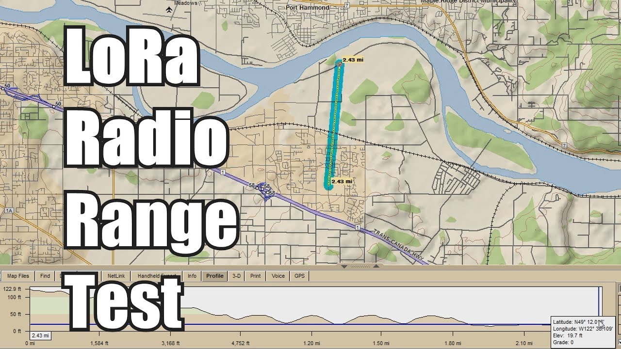
This video will show the results of my LoRa radio link range test. Tips on how to increase your LoRa transmission range will be covered. E32-915T30D Lora mod...
lethal pine
But I need that for an rfm69
I have 2 rfm69 hats for raspberry pi. Also, tomorrow i will be "war driving" my quarter wave antenna
Also, if the poc works this weekend I may get a deal to take it to production.
You bet it'll be on github before this though
broken hinge
@quaint matrix Thanks 😃 That is basically what I had in mind - do you per chance have pointers to where I might find the details on this?
restive fjord
Wild guess here: best to learn USB cold on the hardware, to see if that's what you want to put up with. USB programming isn't trivial to accomplish (I've done it).
If you get that far, then you can start dreaming. ;)
@broken hinge @quaint matrix wrt the above two lines. ;)
BTW the USB driver for CircuitPython is a very good place to look for ideas wrt USB support.
If you're interested, Atmel Start does support USB for the supported chips (that's how I'm doing it on bare-metal hardware approach, for SAMD21 and SAMD51 chips).
quaint matrix
yeah usb isnt trivial. I agree to take a peek at how circuitpython and maybe a few others did things.
youll want to learn how it sends packets, about hid and what you need to act like a hub and send disconnect/reconnects
you can also read the usb specs but its pretty complicated
restive fjord
hehe yeah.
Also one end of the wireless magical connection plays role A and the other end plays role B and those two don't share everything in common when it comes to programming the microcontroller to 'do' USB in each instance.
So you would have to do both!
I think one is called 'host'.
(you will not find an example that does both modes as a single example in Atmel Start, iirc)
https://github.com/wa1tnr that's my github; if I've done it, that's where it'll be found.
Yeah, 'CDC' and 'ACM' are two buzzwords for this.
quaint matrix
yeah i feel like what you might have to do is figure out how to code a usb hub. but the difference would be that you dont just send all the data via usb to the main computer.
instead you split it, one side is the hub connection to the devices, and then you forward that data over bluetooth. then the other end acts like the hub connection to the computer
restive fjord
https://github.com/wa1tnr/samd51_USB_CDC_ACM_basic/blob/master/usb_start.c
is a good place to start looking.
It's Atmel Start generated code (might have some edits; haven't looked at this in a while).
Not sure this particular project runs on the hardware or is broken. Been a while!
I would say overall that if any of this is news to the OP then the project is going to be unusually difficult to accomplish in its entirety. I would plan on allocating 6 months to it, making it the one project that is worked on the most, of anything going current in your project list. ;)
BTW doing this with RS232 (serial) isn't all that trivial, but it's an order of magnitude easier than also using USB on top of all the other challenges.
I think ZigBee is the off-the-shelf solution (maybe a dated solution) for some of this.
(never tried ZigBee)
There is also a 'simple' Adafruit project that takes the fundamentals of Bluetooth and microcontrollers, and does something that pleases the beginner.
▫ 🔸
I accidentally noticed that when I listened to a Twitch stream outside on my front porch, the WiFi connection far out-performed the same distance when traversed by Bluetooth.
So it makes sense for me to leverage WiFi over Bluetooth, for similar use cases.
Unfortunately, the use case I want to work with most frequently only allows a Bluetooth solution (WiFi can't figure into it).
broken hinge
Bluetooth is a hard requirement, but the distance is luckily short. No stranger to HID programming or protocol packing, so overall I am not worried about feasibility - just looking for resources. I appreciate the links - they look like excellent starting points.
primal warren
So, basically a Bluetooth USB extender?
restive fjord
https://www.youtube.com/watch?v=L7lEDS6xj5w
Based on this YouTube video (pointed to by a lifehacker article) I think I would revise my thinking on this (maybe a lot).
@broken hinge @quaint matrix @primal warren
Now I'm more thinking about what Adafruit has already done in the way of letting you hook up a mouse or a keyboard to a SAMD based microcontroller board.
I just don't remember which direction it operates in. ;)
I THINK the Adafruit approach was (is) to emulate those devices, so that your micro can use other controllers (rotary encoder comes to mind) as an ersatz keyboard (or mouse).
There's probably an off the shelf gadget you can buy that will recognize your existing USB mouse or Keyboard, and 'do something interesting' with that recognition.
primal warren
It just lets a processor emulate the usual range of HID devices and provide input like they would (mouse movements, key presses, whatever).
restive fjord
That video (from about 2014) seems to indicate plugging an existing USB keyboard into a small form factor device was thought of then, and accomplished by one of the hobby houses.
primal warren
It's a little tricker to emulate a USB host (so you can plug a keyboard or whatnot into it).
quaint matrix
Yea I have played with usb input, they don't emulate anything software wise. They just send a descriptor that says what they are and how they are going to send reports, then send them
restive fjord
The video also suggests this application may be bandwidth limited (at least during the first iteration of it, while debugging stuff).
quaint matrix
Yeah that's my big concern. You'll have Bluetooth and USB headers
restive fjord
(I'm thinking 'simple' buffer' overflows, by poor practice wrt so-called 'ring' buffer)
quaint matrix
And the packet sizes won't line up most likely
Yeah and flow control/latency issues
restive fjord
Right. But the basics sound sort of do-able.
I myself (haha) found the ring buffer issue to be gnarly (went beyond my immediate knowledge). I understand the approaches used, that I've seen, but haven't implemented any of them successfully (electing instead to use very tiny buffers, on the order of 8 chars at a time or less haha).
I'm going to assume that this kind of project takes its basic shape as a very small device that a USB keyboard plugs into, and that it has its own battery, and that it is used (at first approximation) to provide a standard USB keyboard to a laptop that does bluetooth (but for some reason, direct USB plugin isn't wanted, at all).
So you could, for example, buy an existing USB to bluetooth bridge (hub) that talks to the laptop only via Bluetooth. The laptop's (wireless) protocol stack has to speak Bluetooth (only) to that hub.
(it also has to understand why you're trying to do this, somehow)
▫
Seems to diagram out to a home-made USB dongle that plugs into the PC. Inside that dongle is a bluetooth radio, and enough electronics to talk to the host PC via hardwired USB.
On the other end is another bluetooth based box/dongle that accepts another USB connection (ostensibly from a keyboard or mouse) and it's main job is to talk (bidirectionally) to the (homemade) bluetooth dongle plugged into the PC (via USB).
So the first question in my mind is, are any of these presupposed by the industry, and offered for sale? ;)
The youtube video guy put up a github repo wrt his vids:
https://github.com/juancgarcia/HID-Relay
one prominent vendor seems to sell a usb host shield.
Some old school stuff for the AVR and USB:
http://www.fourwalledcubicle.com/LUFA.php
cp2104 (serial to USB bridge) can talk to the PC to provide RS-232 connection from a project to the PC, via USB. I think it can do up to five lines (CTS, RTS that stuff).
Presumably this would let the PC talk to the bluetooth radio that has a TX/RX pair for its serial interface.
The host side seems much more limited. I think a lot of people 'cheat' here and use Linux with something like a Raspberry Pi, to acquire the USB HID device to be extended over radio to the (waiting) USB-only host PC.
broken hinge
@primal warren Indeed - same project still, looking at using the per-board programmer USB ports to supply a USB forward when something else is plugged in.
The primary use case is not additional HID (though as a general hub, that would be a secondary goal as well), but rather USB mass storage.
broken hinge
If you put things in simplified network terminology, what I am looking to do is build a router, while the mentioned issues seem primarily applicable to a switch. For the “fast as possible” HID protocol, I am definitely going to have to do a lossy forward. For other protocols, I would expect that the final interface just adds obvious bottlenecking to the whole thing. Which is fine - this is about convenience, not performance.
For HID devices, ideally I would special case per category - compressing for keyboards and likely just skipping for others. That seems mostly like something best ad-hoc adjusted.
primal warren
Seems doable. You could do it the simple way and just encapsulate the USB packets and send them via Bluetooth, but it sounds like you want more smarts to it, so it can optimize various kinds of traffic. You'll need special support for enumeration as well.
lethal pine
I got the rfm69 module to talk to each other with an app

Devpost
Long range communication for when you are in an emergency situation of don't have a connection.
@restive fjord since you said you want to see it
We won best hardware hack and JP Morgan Chase social good challenge
restive fjord
thank you
 burnt kite
@fast badge i would put a link to your forum post here. the radio folks here may not frequent the forums...
 fast badge
Hi I am having a problem with wifi breakout board! I’ve checked all pins 10x I’ve read all setup confirigration of pins 10x I’ve used different Arduinos to try to upgrade the firmware but it gives me same error! Please help I’m stuck I just purchased this item and it unusable please help me find a solution! https://forums.adafruit.com/viewtopic.php?f=19&t=149192
 flat tapir
@fast badge Would it happen to be the xbee explorer shield?
fast badge
@flat tapir no it’s not the xbee shield
flat tapir
I need help finding appropriate hardware.
My project is a multi-sensor network:
• A mother/child network of one "mother" and many "children". (I find the computer science terminology for networks very unsettling)
• The "mother" is a stationary device that records and displays the data from the "children" in real-time.
• Each "child" streams very accurate analog data from one on-board sensor, directly to the "mother" in real-time. They are portable, battery powered, and as small as possible.
• Only limitation is that the only coding I know is arduino.
primal warren
Sounds like low bandwidth requirements. What sort of distance?
flat tapir
@primal warren Well, it's a guess, but I would say that the distance should never be larger than say.... a conference room. That's still probably overkill. My biggest worry is interference. If I had the luxury, I'd like it to be heavily shielded from interference (60Hz, 2.4GHz, 5GHz, and others I am not yet aware of). It will eventually be used in an environment with very heavy signal interference.
It's a proof of concept right now, so I'd like to focus on distance.
primal warren
So probably not Bluetooth, but perhaps WiFi, LoRa, or FSK at 900MHz. BLE would give superb battery life, but LoRa is no slouch.
flat tapir
@primal warren I had originally considered series 2 xbee.
primal warren
I remember your ongoing travails with XBee, which is more of a mesh architecture than the star you describe.
LoRa does have the concept of a base station, and is normally optimized for distance and power saving, but it has pretty solid noise immunity, and distance can be traded off for even more.
I'm thinking 900MHz for the "as small as possible", but 433MHz might buy you some more noise immunity (they're both ISM bands, but at least you're dodging the interference sources you mentioned).
flat tapir
@primal warren Transmission accuracy is the absolute most important part. I am basically trying to turn a wired system into a wireless one. What ever is picked up by the sensor needs to ultimately appear on the screen exactly as it would be if it was a wired connection.
primal warren
As long as you can tolerate some occasional time delay, that should be doable.
flat tapir
@primal warren That's a sacrifice I am going to have to make. It's that or sacrifice on interference protection.
primal warren
It's a real problem with things like cellphones: by the time the stations realize there's been a packet error, it's too late, they can't prefetch (like CD players) or request retransmission (like non real time systems).
There are a bunch of more exotic possibilities, but they all tend to require more power or size.
For your use case, I'd probably go with LoRa or FSK with a reliable protocol layered on top (there's a good Arduino library that does this).
flat tapir
@primal warren Okay. I am not familiar unfortunately. Any specific device(s) in mind?
primal warren
Here's one possibility: a Moteino. This board is barely larger than a postage stamp and includes the CPU and radio. The blue wire is the antenna.
And yes, it's Arduino compatible. To save space, I didn't even solder headers on it (I program it with clip-on pogo pin array).
Another possibility is a LoRa Feather, which includes the power supply circuitry https://www.adafruit.com/product/3078
My Moteino project was intended to just be used in the range of a few meters, but as circumstances had it, I ended up running it across a large convention center in a very electrically noisy environment and it worked fine. However, I was using the less-efficient FSK version and battery life wasn't that great when transmitting often. Note that the board is available with an optional 4Mbit flash chip, which can be useful if you want the sensors to buffer data.
Here's a pic of the pogo pin clip I use to program it.
flat tapir
@primal warren This is actually very helpful. There seems to be quite a few LoRa Feathers. Is there a specific reasoning behind product 3078? That covers a lot of issues and the coding portion. But what about the network set up part? And how would the "mother" device be setup in the center of the "star" network?
primal warren
My thinking behind 3078 in particular is threefold. One reason is the frequency: 900MHz requires a smaller antenna than 433MHz (but as I said, 433MHz propagates better over longer distances, which might be useful for interference robustness, depending on the environment and distances).
Another is that it has a 32U4 CPU, which is very similar to the ATmega328 used in an ordinary Arduino, but with built-in USB support (another possibility could be the M0, which is a much more powerful CPU that's well-supported by the Arduino environment). The last reason is simply cost.
As for the "mother" device, there are two ways to use LoRa: there's the plain version where nodes can talk to each other directly, and there's the "LoRaWAN" version where nodes talk to a base station that has more advanced hardware to manage multiple conversations at once https://www.thethingsnetwork.org/docs/lorawan/.
The drawback is that the base stations are less common and more expensive than simple LoRa transceivers.
flat tapir
@primal warren Hmm, I'm getting that "two steps back" feeling.
primal warren
You're trying to do something fairly complex, and I obviously don't know all the parameters. Is there something in particular that's making you feel two steps back?
flat tapir
@primal warren I feel like what I want to do is exceedingly simple for a large majority of the hacker community. I see IoT everywhere lately. And the only reason none of those options is viable for me is the fact that they require something outside of my skill and knowledge set. Even though I am willing to purchase parts and start over again repeatedly, I can't do that if things start to get pricey. And from the few LoRaWAN I can find online, you are correct, they are up there.
primal warren
In my understanding, the overwhelming majority of IOT out there doesn't rely on reliable transmission. If a temperature reading doesn't get through, no big deal, we'll catch the next one or the one after that. They also seem willing to just not work in bad environments. Since you want to replicate the reliability of a wired network, things are harder.
I don't mean to sound facile, but I generally expect to spend some time expanding my skill set and knowledge for each project I do.
And yes, LoRaWAN is expensive: it might not be the right practical answer, even if it's technically appealing. You may well do fine with XBee, FSK, or plain multinode LoRa, just arranged so the hub pairs with each of the remote devices (I share your uneasiness with the "mother"/"child" nomenclature).
flat tapir
@primal warren Well, after some digging, I found these. Opinion(s)?:
https://www.robotshop.com/en/firebeetle-covers-lora-radio-915mhz.html
https://www.robotshop.com/en/iot-microbit-lora-node-915-868-mhz.html
https://www.robotshop.com/en/iot-lora-node-shield-915-868-mhz.html
https://www.robotshop.com/en/mesh-bee-mcu-zigbee-pro-module.html
https://www.robotshop.com/en/lora-long-range-transceiver-bee-915-mhz-north-america.html

Wireless transmission module with a chip SX127x LoRa and a built-in PA (power amplifier)
Operating Frequency: 900MHz~1000MHz (typical value: 915MHz)
Receiving Sensitivity: -139dBm / Transmission Power Range: -1dBm~20dBm
Maximum RSSI: 127dB / FIFO Volume: 256bytes
Supports lon...

IoT Long Range Node for micro:bit
RAK811 LoRa Radio with full LoRaWAN Stack embedded
Supports LoRaWAN Connections and LoRaP2P Modes
Low power: uses less than 50mA during transmission
Compatible with: BBC micro:bit Programmable Board

IoT Long Range Node Shield
Frequency: 915/868 MHz
RAKWireless RAK811 based on Semtech SX1276
Compatible with The Things Network, in conjunction with Arduino

2.4GHz wireless transceiver with JN5168 microprocessor
Range: Up to 30m (Indoor/Urban), line-of-sight: up to 100m (Outdoor)
Interfaces: UARTx2, SPI, I2C
Connectivity: Socket compatible with XBee

Frequency Band: 915 MHZ
LoRa Modem
FSK, GFSK, MSK, GMSK, LoRaand OOK modulation
XBee form factory
primal warren
The XBee form factor ones are attractive, but you've had troubles talking to them (I'm still curious what happened to the serial data).
The FireBeetle seems small too, but I suspect it needs a CPU as well.
The Moteino I mentioned is small and already has the CPU https://lowpowerlab.com/shop/product/99
Moteino Wireless Arduino Clone
Depending on funds, timescale, and how thorough you want to be, you could try getting a pair of the RFM ones, a pair of the LoRa ones, and possibly Zigbee as well and do some testing in a noisy environment and see how they perform. You could also try a couple of different frequency bands, but at that point you're buying (and doing all the work of integrating) six pairs of boards. For some projects, that might make sense.
flat tapir
@primal warren I do still plan on troubleshooting the TX/RX signals. I don't have definitive proof that anything is broken, so I intend to try to get it working on another project at another time (I am quite stubborn). I might have misread the FireBeetle, I could have sworn it was an Arduino compatible microcontroller and LoRaWAN hybrid. Also, I am considering the Moteino, but I wanted to see if I could find a compatible affordable multi-point module as the "mother".
primal warren
Ah, I missed that detail of the FireBeetle.
primal warren
A possibly-useful writeup of IOT standards. https://www.microcontrollertips.com/how-to-choose-iot-standards-end-game/

How does one answer the question, “What IoT standard should be used?” Usually, I answer this question with, “How can you make money?”
 lunar ingot
Does anyone have experience with Bluetooth 3.0+HS?
 scenic cliff
@flat tapir the lora library named Radiohead has a reliable datagram example which apparently takes care of making sure the transmissions get through.
flat tapir
@primal warren Hmm, that article seemed less about how to choose the right standard for a project, and more about what's wrong with today's society. Either way, it was still very enlightening.
@scenic cliff This?
scenic cliff
@flat tapir the Radiohead library supports those chips. I haven't tried the reliable datagram protocol but I got 16 mile transmission with the Lora feather as tx and a heltec esp32 Lora as receiver.
flat tapir
@scenic cliff I guess what I am trying to say is, where is this diagram that you mentioned originally?
scenic cliff
I said datagram not diagram.
 proper perch
@primal warren got some sauce on that pogo pin clip? I feel like I'm abusing the connector on my programmer (although I don't love the unsupported look of yours either from that photo). commercial? adaptation?
primal warren
That's the annoying bit: I got it from Taobao via Bhiner, which transships items from Chinese vendors. So you pay once to buy the item, then you pay again to have it reshipped to you. Worrisome and inconvenient, but so far I haven't found a better way to buy certain items. https://www.bhiner.com/taobao-agent/42343856957
Bhiner
Taobao agent Available in English. Taobao does not have an English version. But English-speakers can still easily buy from Taobao, with Taobao Agents such as us, bhiner.com
proper perch
yuck. if it was the perfect solution I'd jump through some hoops, but it's not. there's a spring clamp for this on thingiverse but it's not great either. maybe a 3d printed clip made to hold https://www.adafruit.com/product/284, with pogo pins replacing the header?
primal warren
Seems doable.
lethal pine
I know that this may be sort of off topic because it doesn't involve adafruit products but what would be the best for tracking a High Altitude balloon besides systems that involve HAM radio?
I was thinking LoRa or XBee
 rough sluice
@lethal pine don’t think XBee will go farther than a couple miles. Quick googling indicates LoRa might go to 15 km.
lethal pine
But los is increased when you are at altitude apparently
rough sluice
You wouldn't have the curvature of the earth to consider, but that would kick in around 3 miles (depending on how high up the radios are from the ground).
At least from an initial reading, the common APRS radio method would relay your packets out to the Internet, relieving you of the need to keep your own ground radio active during the flight.
primal warren
We usually used a UHF beacon.
rough sluice
In any case, if high altitude is 60000 feet and up, that's a good margin over the 15 km LoRa mentions. I'd assume there's a good reason ham rigs are used commonly instead of LoRa or XBee.
 rose sun
One reason for that might be the exemption for licensed ham users to build their own experimental rigs without having to jump through all sorts of licensing
as long as you stay in one of the amateur frequency allocations appropriate for your license
you're covered
rough sluice
Is that a ham-specific exemption, not generally applicable to LoRa or other stuff in unlicensed bands?
lethal pine
So I guess I should get my license
Lora is unlicensed so you can only really stay in the 916 or whatever it is for the 900mhz band. There are power restrictions and packet duration with lora
Also, 433mhz is actually supposed to be a licensed band iirc
primal warren
It may well be worth your while getting your license. A lot of the questions are electronic in nature so you probably won't have to study much for them. Hams tend to be friendly and helpful, too.
lethal pine
I also want to further develop this distributed network that I was as making using packet radio. Maybe go to something with more power or something
restive fjord
I think your main problem at altitude is .. altitude.
Any pilot can tell you that unexpected things happen when you leave the ground.
Pretty sure cellular service doesn't work, for example.
primal warren
As discussed above, altitude helps point-to-point radio (antenna height helps a lot, and balloons are great for antenna height). Even a feeble transmitter and a twinlead J-pole can be received from great distance when it's up in the air.
primal warren
You mean, something for the antenna to "push against"?
restive fjord
yeah that's about what I was thinking, essentially.
restive fjord
Okay yeah a counterpoise makes sense to me, there.
primal warren
Works surprisingly well with even a walkie-talkie type handheld radio too, even just a wire connected to the antenna ground and dangling will improve your signal (transmit and receive).
restive fjord
I think with cellular the relay stations on the ground don't 'look up' much -- that may be why cellular coverage drops with altitude.
primal warren
Yeah, I think they're aimed for best effect, also at altitude you'd see a bunch of antennæ at essentially the same distance so they'd be interfering with each other.
restive fjord
I've done a lot of bogus indoor antennas and had good results with them. Worked the Ukraine from Connecticut on 25 watts SSB, with an antenna in the attic. Worked Italy on an indoor antenna on the ground floor. ;)
The guy that does the glider videos on YouTube (Bruno Vassel, I think) uses his cell phone while airborne, but it is weak. For him, terrain seems to be a factor; he has to get high enough to see the cell towers. ;)
The Buddipole system relies on off-center loading to change the characteristic impedance of the antenna (to make up for the fact it's not at least a half wavelength above the 'reflector' property of (the) Earth.
When I want a 1:1 SWR I keep the overall length of the Buddipole (dipole, off-center fed) the same, but change the length of the shorter leg.
(moving the feed point further offcenter or closer to center).
(a normal end-tensioned (wire between two trees styled) dipole cannot be adjusted so easily ;)
primal warren
My main antenna is a non-resonant asymmetrical dipole (I called Wireman and asked them to send me the two longest lengths they happened to have on hand), with some wire lying on the ground under it to make the ground "look" more conductive. Tunes up pretty well on all bands, and has a vague lobe aimed roughly at southern Europe. Tensioned the old-fashioned way, with weights. One time a tree branch fell on it, didn't break anything, just lifted up the weights.
restive fjord
Haha. Yeah an old codger ham died in our neighborhood (I never did meet him) and the house was sold.
The new neighbors had no use for his dipole; I asked if I could have it. Was real old school.
primal warren
This was of course in an ice storm, and it had little icicles hanging from it, but when it stretched from the branch, it twisted a little, so the icicles were pointing in a spiral.
restive fjord
Counterweight was like five clay bricks with center bore mounted on galvanized shaft. ;)
primal warren
I had some genuine sash weights, so I used those.
restive fjord
That pulley setup could tolerate about 9-12" inches of tree sway, I think.
primal warren
Sounds like pretty much the same deal. I've become quite fond of Copperweld®.
restive fjord
Come to think of it one end was anchored to the house near the roofline. ;)
I center fed it (annoyed the whole family) because I didn't know what else to do.
(80 meter band full length dipole)
primal warren
Window wire?
restive fjord
I was just a kid, and antennas were not yet on my list of things to put a lot of study into.
I wanted to make CW contacts, mostly.
So as I recall I dropped the coax from the center, to the lawn, and buried it. Wasn't good coax either. ;)
I tuned the 10 meter band all that summer and barely heard a peep, and didn't know why.
School was out so I couldn't ask anybody.
I ended up working Puerto Rico (twice) on 15 meters that summer.
(on an indoor attic antenna I don't think my Mom even knew about haha)
primal warren
Mine's fed with ordinary 450Ω window wire, with an antenna tuner by the radio. I've thought of running coax and power out and having an automatic tuner at the feedpoint, but haven't done anything about it other than buy a tuner which still sits in its box.
restive fjord
The ladder line method worked well for my friend who had his Drake twins in his basement.
I was running Heathkit DX 60B and was afraid of .. a lot of things related to electrocutions. ;)
primal warren
While I have a newer (and theoretically nicer) rig, I'm still using my old vacuum tube Kenwood.
restive fjord
Yeah I gave mine away; I don't know why I did that. The finals were soft on 10 meters, that much I remember.
primal warren
The Kenwood is drifty. There are some modifications that could make it more stable, but I'm thinking of building an outboard VFO for it.
primal warren
Heh, mine's a TS-530S. 😃
restive fjord
Definitely had the paddle bay of switches on the left, and an analog meter on the left.
lethal pine
Also, NIS, you can't use cellular services on a balloon.
I was thinking about having a system that would activated once it got on the ground. A cell signal would be established and it would text us the location of the balloon.
I've ran some models to see where the balloon would land and it would land well in range of a cell tower.
My team has enough for like $300 in funding but I'd like to get the total cost of the flight computer and telemetry at or near $100.
I already have multiple board for the brains but I need a GPS and rf hardware. I believe sparkfun has a gps that can operate at the max height that we are shooting for.
primal warren
Fona 808 has both cellular and GPS functionality.
lethal pine
But would that work as intended?
The president of the club wants real time tracking but I think it's too expensive to do so. Compared to fona 808 or similar.
primal warren
I was thinking of your idea of a system that activated once it's on the ground.
Real time tracking can be done, but that's usually sending the GPS position via APRS, Morse, or somesuch, and RDF: for that, you will need GPS that will function at altitude too.
lethal pine
Ya, the 808 would be once it hit the ground. Aprs would be "real" time
Is there any option that would be better over the other?
Cost wise the aprs is about $150.80 and gsm is about $86.85
primal warren
There are a lot cheaper ways to do APRS.
lethal pine
Please share
scenic cliff
@lethal pine I've gotten LoRa to 16 miles ground-ground.
This was my first attempt. later got 16 miles.
lethal pine
But what were the details? Antenna, elevation etc
restive fjord
That's an island. The transmitter is low; the receiver is up on a hill, 100 meters or more above the transmitter.
lethal pine
I think we are doing aprs and gsm
restive fjord
The summit is at 3000 meters and there's a village 10 miles away that's at 500 meters.
I'd think of that as privileged terrain. ;)
lethal pine
Lol it is
restive fjord
If you're Gus van Sant filming 'Gerry' then you're onto other matters (you are away from artificial noise sources, but you probably got terrain between the two stations).
I would expect 800 feet ground to ground level would be a good achievment in LoRa, in the urban environment.
Basically there are no frequencies or modulation techniques or encodings or robustness of error corrections that can make up for ISM band Part 15 limits (that's what they're for, after all).
Even 2 Watts ERP on 144 mHz is a huge signal improvement at the receiving end.
I've done a lot of simplex work on the 2 meter band, both voice and packet radio.
If your goal is to hear the other station's callsign (only) five times a day, that's one thing. Yeah, you'll see them on MHEARD but you'll also see a timestamp that isn't very recent.

I want to get two range world records: 1. Longest connection to a TTN gateway 2. Longest Low Power Wide Area Network (LPWAN) ground to ground connection Come...
normal drift
@restive fjord I think you are under estimating LoRa. There are so many variables, but my simple tests have worked easily to 1Km.
restive fjord
Okay, I have no direct experience with it.
normal drift
Rfm69 is much more limited...
restive fjord
Can you hear LoRa in a scanning radio at all?
restive fjord
I remember that SDR !
What kind of data rate can you transmit reliably, at 0.25 km?
normal drift

If you've ever been curious about software defined radio (SDR), this USB stick is the easiest way possible to have fun with a powerful, configurable receiver. Packed with the powerful ...
Rates are low. Packets are limited to ~200 bytes. I send a packet every several seconds at fastest. It’s not for streaming!
restive fjord
still that's not bad by packet radio standards.
normal drift
I typically send 20 byte packets
restive fjord
as long as it stays connected until the message is confirmed, that's more than enough. There are also unconnected packets you can monitor with no guarantee of accurate reception, but through redundancy can (maybe) confirm without a bidirectional connection.
Yeah so latency and throughput are metrics that matter, depending on the goals of a given project. Distance is one factor.
normal drift
Lorawan is a neat project. Need more gateways...
restive fjord
btw at those rates of throughput and with that latency, you're still well within the intent of Part 15 ;)
I occasionally see some very interesting SSID's on the WiFi, but they are way down in the noise most of the time.
I miss DXing broadcast television. ;)
normal drift
I see some intriguing “noise” if I just listen on LoRa. I keep hoping to see someone access my lorawan gateway.
restive fjord
I monitored the ham 2 meter packet scene and heard almost nothing.
That stuff came, and went, a while ago. ;) I'm glad I was in on it.
normal drift
I had fun with AX25 a long time ago....
lethal pine
Rfm69 isnt lora though
normal drift
That’s for sure😉
restive fjord
look at nyquist
lethal pine
Wait, so 2m packet radio is dead?
I was thinking about starting to do it after I get my ham radio license
But I have the rfm69 hat but not a lora hat. Do you think I could desolder the rfm69 and add a 95 to it?
normal drift
I am not aware of any issues with 2m amateur radio.
lethal pine
Also, it seems like 69 is not as supported as the 95 is
normal drift
I’d just buy an rfm95 breakout.
lethal pine
Which I find odd as the 69 is cheaper
Ya, I'll likely buy the breakout of featherwing
restive fjord
normal drift
Both are well supported by Radiohead under Arduino. The CircuitPython support is minimal for basic on both but adds tinylora for RFM9x
lethal pine
But community wise, barely anyone uses a rfm69
lethal pine
Post more projects and code plz xD
I tried to write my own code to interface with a phone's bluetooth but it didn't work so I reverted back to adafruit code
normal drift
I use it mostly to relay temperature/humidity to a raspberry pi for posting to AIO. The rfm69 part is very basic.
lethal pine
This is what I did https://devpost.com/software/emesh-io
Devpost
Long range communication for when you are in an emergency situation of don't have a connection.
normal drift
👍Nice project
lethal pine
It was very hard tbh
normal drift
Good luck with it.
lethal pine
Mainly sue to lack of support with community and bluetooth being bluetooth. I've since moved to a different project for now
One that deals with hab
restive fjord
@lethal pine Yeah the 2m packet community is very tiny now.
Just old folks who never gave up on it. Can't find many new TNCs on the market anymore.
restive fjord
lethal pine
So is LoRa the way to go now?
 rich ferry
it's definately worth checking out if there is already an TheThingsNetwork gateway in your target area
point to point LoRa should be doable too if you want to point a high-gain directional antenna at your balloon. Just don't park your base antenna behind 2-feet of concrete, it doesn't do anything good for your range
even with the 2' barrier on the base station I've been able to get packets through a bit over a KM away through a densely built up area using a Feather LoRa with a 3" scrap of wire for an antenna. Probably at least 6 multi-story buildings in the LOS
rich ferry
900 (US)
I think the radio performance is similar between the 69 and 95, but the LoRa protocol stack does more for you.
rose sun
@restive fjord with a lot of setups you no longer need a hardware TNC -- there are software TNCs that work just fine, you just have to be able to get audio between the radio and a computer.
restive fjord
I have passive tablet pen, is there a way to read its data and signal strength with my Arduino UNO? Any ideas?
I want to make simple tablet
quaint matrix
i looked in to how wacom tablets work, it is VERY complicated. ill see if i can find the documents i read again but there is almost nothing on how it really works
this video has a big info dump on them in general https://www.youtube.com/watch?v=nPab7pbOhBY&feature=youtu.be
its about 20minutes in where he messes with its rf signals
the channel has a few other videos on the same subject
normal drift
@vocal veldt are your TTN gateways working? I can't get either of mine to go to a "connected" state on the TTN console.
 proper crane
pepsix63eso
normal drift
Thanks. I’ll keep trying.
normal drift
@vocal veldt looks like an issue with the new Indoor Gateways only https://www.thethingsnetwork.org/forum/t/ttig-not-connected/25892/4 -- I got my Things Network Gateway back online OK. I did have to delete the old registration and reregister. Can't do that for the Indoor Gateway thought I'll give them some time to work it out.

The Things Network
Same issue here. All other gateways we have deployed are not affected, only the single TTN indoor gateway.
 vale kettle
Ok so I created an FM transmitter with fixed frequency of ~108MHz, but my radio picks up a much stronger and cleaner signal at around 65MHz. Why is that? Why is my 108MHz transmitter broadcasting at 65MHz as well?
vale kettle
F, I tried to modify it and now it doesnt work
Even when I reverted it back to how it was before I messed with it
Good I have a spare one tho
But still
vale kettle
Oof I got it to work agin
 young cove
@vale kettle it depends a lot on the design (signal mixed up to 108 MHz, but has image output), or it's a doubler, tripler, etc. Is it your own design or a commercial thing
vale kettle
I found schematic on the internet and built it and it worked fine, but I picked a coil and capacitor for 108MHz, not 65.

I changed the transistor to bc547 and a variable capacitor to 3 4.7pF caps connected in parallel. I also used 4.7pF cap for the one next to the transistor
It delivers suprisingly good sound quality for its simplicity. Of course its only mono
young cove
@vale kettle 3 4.7pF in parallel is a lot more capacitance than 5pF, so you'll be oscillating at a much lower frequency. The tuning is going to be delicate with such low capacitance, and a simple L1 like that. So you're probably hearing harmonics of some lower fundamental. What receiver are you using to detect the frequencies? Look lower than that too, like half or a third or a quarter of 65 MHz
the 4.7pF caps are fixed? or variable?
vale kettle
Fixed
Sorry for not responding, I was sleeping
Yeah, that's what I thought too, 108 must be a harmonic. My receiever is an old multi-band Panasonic radio. I checked entire available range and only got signal at 65 and 108. I used three 4.7pF caps for total capacitance of 14.4pF and I made a coil which inductance should be around 153nH, although I can't confirm that because my meter can't measure coils
vale kettle
I tried removing two capaciors from lc resonance circuit to move that 65MHz signal up, but it just resulted in transmitter not working. Then I found out that bc547 can work only to about 100MHz, so I tried replacing it with 2n2222, but it didn't work either
vale kettle
Replacing coil with a smaller one also didn't help
Maybe You can suggest what transistor should I pick?
primal warren
A BC547 (or the BC548 mentioned in the schematic) has a transition frequency of 300MHz, so at 108MHz, it will have a gain around 3, which should be sufficient if there aren't too many losses in the circuit.
This page https://www.circuitsdiy.com/c9018-fm-transmitter-circuit/ (which gives a slightly different version of the circuit) suggests a "C9018", which is actually a 2SC9018, which has a transition frequency of 700MHz minimum, but I don't think that transistor is current. A quick look at Digikey shows that lots of such transistors are now obsolete. I did find a 2SC5706 (400MHz Ft), which is still available and inexpensive, and a 2N2369, which is more expensive but offers a 500MHz Ft).
You might want to play with your coil parameters and circuit layout to reduce losses (in particular, you'll want heavy wire and low loss capacitors).
vale kettle
I should be able to get 2n2369 at my local electronics shop. It should let me rise the frequency, right?
My circuit is soldered in mid-air
primal warren
That's a good approach for RF. Did you use reasonably thick (or Litz) wire for your coil?
vale kettle
Its a solid copper wire pulled from ethernet cable, so I guess around 22 awg
I'm not sure if You can call that thick
 barren lodge
Anyone has a clue how to wind this up again?
Just wanted to clean the PCB, but as I opened the case the wheel became loose and fall off...........
young cove
@barren lodge This kind of thing is usually in the service manual for the radio, which you can often find online.
barren lodge
Much much thanks @young cove
You saved my day
young cove
you're welcome! Glad you were able to find the service manual.
barren lodge
Also didn´t thought that i find it that fast
 slender yarrow
Hello all. I'm making myself available as an elmer, or helper to others.
 silver marten
hey guys, i am back. any new radio stuff that has come out? also looking for any suggestions on a mobile screwdriver antenna that will tune with my yaesu FT-991
primal warren
I'm torn between "roll my own" and "grab an unloved ATAS-120 and rebuild it".
 daring venture
Do you know what is the range of the RFM69HCW 433MHZ at full power ?
The website say 5km lineofsight but don't tell the frequency
normal drift
Where to you see 5Km as a range? -- the product page says Range of approx. 500 meters, depending on obstructions, frequency, antenna and power output
I would not expect more than a few hundred meters at best.
Ah never-mind I see it now They can go at least 500 meters line of sight using simple wire antennas, probably up to 5Km with directional antennas and settings tweakings Good luck with that 😉
slender yarrow
At 1/10 Watt max, that's pretty good. Mind you'll never get that 500m range unless it's on an airborne platform or otherwise in clear line of sight.
If you want to go futher, you'll need either a directional antenna or additional Power Amplifiers, I'd recommend a linear rated for 70cm band and a liscense may be needed depending on how much power you need to go as far as you need.
normal drift
@vocal veldt do you know of a “full” lorawan node implementation for raspberry pi? Re: this forum discussion https://forums.adafruit.com/viewtopic.php?f=50&t=152407
 vocal veldt
@normal drift that user also submitted a Issue about this and I was gonna look into it this AM
I did a LOT of testing before working on TinyLoRa, iirc there's no way to see the RSSI from the node itself, only the gateway since it's getting a response
There's no Gateway->Node communication built into TinyLora, it's unidirectional
normal drift
Right - I just wondered if there was a more complete LoraWan implementation for the RPi that was bidirectional.
vocal veldt
Anything which uses the LMIC (LoRaMac-in-C) implementation would probably be a different device class
normal drift
I posted a link to one WIP for LMIC in the forum discussion. I have not tired it yet.
vocal veldt
Most of the RasPi stuff on the web is a LMIC implementation with a HAL
the LMIC library is usually consistent btween them, the HAL varies and is (often) broken/not working/out date, unfortunately
normal drift
Yup — seems to be the case...
I was trying not to be too discouraging to the poster...
vocal veldt
I did a lot of testing back in the fall when I was doing a lot of this work.
normal drift
I hope to have more time to get back into it soon. Several things I want to try both with LoRa and LoraWan
vocal veldt

GitHub
LoraWAN-in-C library, adapted to run under the Arduino environment - things-nyc/arduino-lmic
this is the best implementation of LMIC tbh
TTN-NYC has done a lot of work on the original IBM library, but it'd need a HAL or something similar to run on a Pi 🤷
normal drift
Thanks - I’ll take a look at it.
daring venture
@normal drift it's for a rocket so I have both direct line of sight and airborne platform
Were I can find a directional antenna ?
@slender yarrow what you just said is for 960 or 433mhz ?
daring venture
And what about the RFM96W ?
primal warren
Directional antennæ tend to be a little bulky for rockets, also rockets spin and wobble, so you may not want something directional. You can, of course, use a directional antenna on the other (fixed) end: that's a common approach (like the big dishes used to talk to spacecraft, rockets, and the like).
There's an appealing directional antenna built out of a printed circuit board in this Hackerbox https://www.instructables.com/id/HackerBox-0023-Digital-Airwaves/
slender yarrow
@daring venture That goes for anything UHV/VHF. Asside from tropospheric ducting (where a thermocline inversion layer acts like a large airborne coax cable), you are restricted to visual range.
Any objects in the path between transmitter & receiver will reduce the effective range. Now since it's on a rocket (presumably going up in a field) your range can be quite substantial even with 1/10W transmit power. I easily held a conversation with 1W to someone 50 miles away when I was 350ft up on an observation platform.
daring venture
@slender yarrow my rocket goes at a maximum of 5km so do you think the RFM96W will be ok ?
I use this type of antenna
primal warren
I'd probably use a dipole (with counterpoise) or J-pole wire antenna to save weight and get more radiating length. Depending on the diameter of your rocket, a loop, helix, or Moxon/turnstyle antenna might also work.
primal warren
I'm guessing you could get more signal out of a wire antenna, but the ready-made one is sure easier.
daring venture
Why a wire antenna can be more effective than mine ?
primal warren
I'm guessing that one is a "shortened" antenna where the wire is coiled up inside to save room. This reduces the antenna's effectiveness. A simple resonant wire dipole will likely be more effective (depending on the frequency you're using, and the size and construction of your rocket).
slender yarrow
They call that kind of antenna "rubber dummy load" because it's inefficient. It's a monopole vertical antenna with no counterpoise or ground radials.
using a pair of wires cut to appropriate length for what frequency you're using will make a great dipole antenna (which is the closest thing to a perfect radiator as you can get.)
A J-pole would also work great. At an altitude of 5km, your primary worry might be exceeding the engineering tolerances of the RFM96W.
daring venture
But adafruit said that the RFM96W can exceed multiple km
And I have another problem 😢
I think the 433mhz radiation genrate noise on my lora and I need to reboot it too start reception for few seconds and I need to reboot it again
primal warren
It can exceed multiple km under ideal conditions. Your best bet in general is to optimize as much as you can with efficient antennæ on both ends.
And yes, radio transmitters generally cause noise problems for nearby items. If you're using both LoRa and another transmitter, you'll have to figure out how to separate them (with time, shielding, filtering, or distance) to minimize their interference with each other.
A bunch of us have heard the result when someone leaves a cell phone near an open microphone ("BZZT! BRRP-brrp-brrp-brrp!")
daring venture
Thanks a lot !
slender yarrow
Hope your rocket has an epic sendoff & you capture it back intact quickly after landing.
daring venture
Thank you 😉
 glad sierra
would it be fair to compare the Bluefruit LE Sniffer to the UbertoothOne ?
slender yarrow
It would. But it'd be akin to comparing a Prius & a Camaro.
The Ubertooth One can act as any kind of BT device. It can transmit & receive. If I'm right, the Bluefruit LE Sniffer is just a sniffer & is more or less passive receiver.
slender yarrow
Give me a moment...
glad sierra
I was not clear if the Bluefruit LE Sniffer could be modified to transmit. Also, I have not found info regarding its range
slender yarrow
OK, it can only sniff BLE4.0 transmissions it looks like.
proper crane
Yep.. Sniffer only does BLE. Just in case you're new to it, Bluetooth Low Energy is it's own standard, separate from other Bluetooth protocols. All other Bluetooth protocols you'll need something else, like the Ubertooth One.
silver marten
i guess this should go here:
are there any tutorials on how to properly utilize a wifi router running WRT?
slender yarrow
DD-WRT or OpenWRT?
silver marten
open i think. i have one router that has open on it and a linksis wrt1200ac that i want to put wrt on.
slender yarrow
Is it on the OpenWRT compatibility list?
silver marten
yup just checked
and it is more involved than i want to deal with on the linksys. it has 2 boot partitions
plus need to get ready for field day
 gaunt kindle
Hi. Anyone know if the RFM95 has an impedance matching network already on board and what the ANT port is matched to?
normal drift
@gaunt kindle see section 2.5 of the data sheet for the rfm9x modules https://cdn-shop.adafruit.com/product-files/3179/sx1276_77_78_79.pdf
it is not completely clear to me (hopefully it is to you) if the chip provides the matching or not 2.5. Chip Specification The tables below give the electrical specifications of the transceiver under the following conditions: Supply voltage VDD=3.3 V, temperature = 25 °C, FXOSC = 32 MHz, FRF = 169/434/868/915 MHz (see specific indication), Pout = +13dBm, 2-level FSK modulation without pre-filtering, FDA = 5 kHz, Bit Rate = 4.8 kb/s and terminated in a matched 50 Ohm impedance, shared Rx and Tx path matching, unless otherwise specified.
gaunt kindle
It tells me that both paths are 50ohms matched. So that's all good
silver marten
once i get my shack together and the antennas put up, i plan on making a automated antenna disconnector when lightning is near by. i was a vid on fb of one
it would also be nice if the weather in Ky would be nice for 6 hours, so i can test some things for field day, but not likely
vale kettle
Hi! I built this fm transmitter circuit https://maker.pro/storage/jAk7d0m/jAk7d0mpVUldS0fdNNAGhPERm6LhgXhllXe6iBXT.jpeg but I changed the transistor to 2n2369 and variable cap to fixed 3x 4.7pF. The problem is that I can't tune the frequency. Desoldering caps and changing coils does very little to nothing. It transmits an around 67MHz.
Am I missing something? I'd like to rise the frequency so I can receive it with digital radios that can't go below 88MHz
Please ping me when You reply
primal warren
@vale kettle The transistor you chose is probably not a good bet (its transition frequency isn't even specified), and you probably have a bunch of distributed capacitance pulling down the resonant frequency.
slender yarrow
Thanks @primal warren
vale kettle
@primal warren You suggested to use this transistor
primal warren
Hmm, weird. I wonder if I was looking at a different manufacturer's data sheet.
Looks like SGS-Thompson and Central Semiconductor give an fT of 500MHz, but ON Semiconductor and Microsemi don't give one at all.
vale kettle
Do You think that distributed capacitance is enough to pull resonant frequency so much down? My tank circuit was calculated to have a resonance frequency of 108MHz, but in reality it transmits at around 65. And after I changed my coil to a one with much smaller inductance the trannsmission frequency didn't change much
primal warren
You're talking about single digit picofarads of capacitance: that's a VERY small amount. Even a couple of wires near each other can have more capacitance than that. For VHF circuitry like this, layout requires a lot of special considerations.
I saw one circuit that didn't work, and the problem was that a capacitor was lying down instead of standing up, and the stray capacitance from that was enough to keep it from operating at all.
vale kettle
But still, I have 3 capacitors in parallel in my tank circuit, so removing some should even that out. But it doesn't. Instead, when I remove one cap, frequency goes up a little, but not much, and when I remove two it just doesn't work. Same goes for changing coil inductance - I changed my already tiny coil to a one with 2 less windings and it still didn't rise the frequency
primal warren
Sadly, that's about what I'd expect if there's too much distributed capacitance.
vale kettle
:/
primal warren
What sort of construction are you using? I'd probably go with airwire, Manhattan, or ground plane for a circuit like that.
vale kettle
My circuit is soldered in mid-air
primal warren
Hmm, that should be okay.
vale kettle
I changed my coil to 1 turn, and now it seems to work at 108MHz
My sound is quieter though
And stupid digital radio still won't pick it up
primal warren
Yeah, it'll probably be lower Q, so you may getting lower amplitude oscillations. You can try coupling it to an antenna, but that can (of course) also affect the operation of the circuit. Putting a better antenna on your digital radio shouldn't be hard and ought to help make it more sensitive and (depending on the antenna) directional.
vale kettle
Nevermind, it's still at 70
108 is agin probably a harmonic
70 is crisp and loud
Probably even a piece of wire instead of a coil would not bring it up enough
tiny dust
I made a calculator for the amount of bits to truncate in a CIC decimator
The only code i can find online is a Matlab version so i made it in python
tiny dust

GitHub
Some tools to help me design Astraea, my SDR. Contribute to hatsunearu/astraea-tools development by creating an account on GitHub.
 lavish valley
Why did i talk in general about my stereo when you have #help-with-audio and #help-with-radio 😑
And why is this even a channel radio is still in audio
rough sluice
Radio is anything transmitted over RF. Doesn’t have to involve audio at all.
lavish valley
Ok
slender yarrow
He's full of 💩 & his eyes are brown.
Yes, you can sidechannel by studying the power usage on the main logic board, but that's more of an attack against servers, individual PCs are too small a target.
Sidechanneling WiFi with one's ears? Nobody can read CW that fast.
rose sun
not to mention WF is RF, ears are not
power supplies and circuits give off RF, which is why it is in theory possible
but theoretically possible is nowhere near the same as practical to do
 little epoch
Everything is about threat model.
(but I doubt you can do anything useful with your ears and someone's wifi)
rose sun
Unless human ears can detect RF, or unless WiFi systems produce modulated sound in a reproduceable manner, the only useful thing you can do with ears and WiFi is social engineering.
lethal pine
So I cant get my ble uart friend to work any more
I got it to work earlier but now it's saying the it cant find the board after it uploads the sketch.
Serial monitor has an error at setting url to adafruit.com that it's too long.
I'm using hardware uart on itsy bitsy. I'm setting the hw name to serial1 in the main sketch because i was getting errors that it cant find the hw name.
 spiral swan
Are there any plans for a BLE Sniffer that supports BLE 5.0?
slender yarrow
I think Mike Ossmann may be working on that either now, or sometime soon.
flat tapir
Can someone help me understand "channels"? As in, could you compare and contrast the difference between say 4 channel transmitter/reciever pair vs a 5 channel pair? Also the difference between say a 2 channel transmitter/reciever pair and a 2 channel wired circuit? And also the difference between a channel that allows for variable input vs one that only has "on or off"?
primal warren
Unfortunately, "channel" can have (at least) two meanings. There's the "TV channel" type meaning, where some units can communicate on a choice of frequencies. Then there's the "radio control channel" meaning, where multiple signals are effectively multiplexed onto a single signal. I'm guessing you're referring to the latter here.
The usual RC protocol is a fairly simple serial protocol, where the transmitter sends a series of pulses, one for each channel. The pulses themselves are modulated similarly to the way an ordinary servo works, one after another (sometimes the servo pulse width modulation is converted to pulse position modulation for transmission). The receiver does the opposite process, demodulating the first pulse and sending it to the channel one pins, the second pulse goes to the channel 2 pins, etc.
I'm less sure about on/off channels, I vaguely remember that internally they're treated the same way, but some postprocessing just uses "less than 50%" as off and "more than 50%" as on.
Found this possibly-helpful visualization online
flat tapir
@primal warren that is helpful, actually. I guess I just have trouble believing that all the commands (even in high resolution) are transmitted and recieved in a kind of "single file line" of sorts. (This diagram looks just like MRI pulse sequences)
slender yarrow
It works much like USB.
Sampled at a certain rate, transmitted across at high speed & then demuxed at the same rate as original sampling.
primal warren
It takes advantage of the fact that servo pulses have a low duty cycle (generally 1-2ms wide at 50 pulses per second, which works out to one every 20ms). Many servos won't even work right if you send pulses more frequently (there are some "digital servos" that can accept pulses more frequently).
flat tapir
I see, so that explains why the Spektrum dx20 gets away with having 20 channels. It still amazes me how that's done while simultaneously frequency hopping multiple times per second in order to avoid interference. (I forgot the process name)
primal warren
I'm guessing the more advanced ones like that digitize the signals and send them as packets and then reconstruct them on the receive side instead of more-or-less just multiplexing the existing signals onto a carrier. Once you've moved to packetized digital data, it becomes easier to use more complex carrier and modulation techniques like spread spectrum, etc.
 amber flare
would this somewhat relate to DCC
I've been wondering how those trainsets are able to relay signal/speed control over just the power rail
primal warren
I'm guessing they work like X10 or shared-cable antenna rotators, and modulate the information onto an AC carrier, then separate it from the power with capacitors at the receive end.
amber flare
oh what I mean is like, toy trainsets
@primal warren lovely, it'll be some time before I'll find out
primal warren
I did a little reading and it turns out DCC works a little differently from the usual "AC signal riding on top of a DC signal" that I expected. It actually sends digital data as power, so a positive voltage is a 1 and a negative voltage is a 0. The trains rectify this to get their power, and monitor the polarity to get their data. Basically the same as sending differentially modulated data down a pair of wires, but at high power.
primal warren
Some good data here http://www.trainelectronics.com/DCC_Arduino/controller.htm
While I'm not a fan of wikipedia in general, their writeup on DCC isn't bad https://en.wikipedia.org/wiki/Digital_Command_Control
amber flare
I did some reading myself and it looks like I have to look more into multiplexing soon
Great something I can actually try out
I read up some here https://dccwiki.com/DCC_Tutorial_(Power)
primal warren
I like the Arduino implementations where you could actually play with it and see how it works
amber flare
yeah, looks a little dangerous though
No voltage drops, currents in excess of 5-10A
I'll slate in a little DCC little project next month and see if I can start hacking at those japanese toy trainsets
primal warren
It's not a "set things on fire" amount of current, and the voltage is low, so not too dangerous, just include fuses and try to avoid short circuits. I suspect you could either use a lower-power booster or a little series resistance (and still a fuse just in case) to limit the current if you wanted to be safer when you're getting started
amber flare
I'll definitely toe poke my way forward for this. Could I pick your brain at some wireless related questions. Not sure where's the right place to ask for it
primal warren
I think this channel makes sense for wireless questions
amber flare
I'm taking my first baby steps into the radio communications domain
looking to understanding the tradeoffs between the different communications protocols and their energy use
I know its probably a deep, deep topic but I'm a Kinesthetic learner
primal warren
Yeah, like all engineering it's tradeoffs (bandwidth, distance, size, power draw, etc.)
amber flare
is there somewhere I could start off? I'm looking at these 433mhz radio transceivers
and I recently got a pretty decent usb current monitor
I'm hoping to monitor battery voltage as a first project, and just communicate its analog value to a base station
primal warren
The Radiohead library is great if you're using RFM69 style transceivers or similar. It lets you do a variety of modes and modulations.
There's some good information in the HopeRF data sheets (or data sheets for whatever hardware you're looking at)
amber flare
Ok, so https://github.com/PaulStoffregen/RadioHead and HopeRF datasheets. Are there any hardware that you would recommend to check out?
GitHub
Packet Radio library for embedded microprocessors. Contribute to PaulStoffregen/RadioHead development by creating an account on GitHub.
primal warren
There's a LOT of hardware out there to choose from, and I've sampled a fair bit of it. I'm fond of the RadioFruit Feathers for their versatility and high level of integration, just solder on a short wire antenna, plug it into a USB port and start transmitting. https://www.adafruit.com/product/3177
If you already have a CPU and just want the transceiver in a breadboardable form factor, that's available too https://www.adafruit.com/product/3071
The breadboard version might be useful to you if you want to measure the transceiver power draw separately, but you'd need a direct wire power monitor for that instead of a USB version.
amber flare
do the types of antennas affect the transmission range/quality?
primal warren
Yup, they sure do. You can save a lot of power with a high-gain antenna.
amber flare
hmm the onboard RFM69 HCW packet does look like quality-of-life enhancement. But I'll probably get modular ones to understand a little more about its wiring
primal warren
Then you can use any CPU you like, too.
amber flare
I'll just get a range and try them all out
are there any diagnostic equipment needed for radio
I dont have a logic analyzer
primal warren
Some things are nice to have like an SWR/power meter, but not required. You can get useful stuff like signal strength measurements from the RFM69.
An antenna analyzer can come in handy if you're rolling your own, but simple wire antennæ you can just cut to length, and antennas you buy should already be set up.
amber flare
ok I did a google search on radio atennas
it looks like low frequency radio uses a totally different set from wifi u.fl antennas
I hope this isn't going to grow into another collection in the house lol
unless I can find another way to make this relevant to the workplace 🤔
primal warren
One simple trick for better performance with a simple wire antenna is a counterpoise, just dangle a wire from a ground pin pointing in the opposite direction. It's like it gives the antenna something to "push against". I've even done this to good effect with cheap walkie-talkies.
amber flare
alright I'll try that out
slender yarrow
Just remember, it's a form of light.
 golden harness
I'm trying to build a circuit to receive the signal from a 433MHz remote, the type you use for your garage door. RF being hard, I'm struggling, but my biggest problem right now is that I'm unsure if ASK or FSK is the standard for those garage door remotes, so I can't even begin looking for receiver ICs. Anyone know this?
Alternatively, does anyone have any ideas for how to more easily integrate a 433MHz receiver into my semi-space-critical PCB design?
I'm also kinda considering just using a ESP-WROOM-32 or something as my receiver, and letting a phone be used as controller/making a bluetooth remote myself. Then I won't have to go into a lot of that RF stuff I don't have any experience with. Thoughts?
primal warren
Hmm, I don't know what the modulation standard is, ASK, FSK, or OOK. This chip doesn't seem to say either: https://cdn-shop.adafruit.com/datasheets/PT2262.pdf
slender yarrow
According to Samy Kamkar's research using Rolljam, many of them use OOK (On-Off Keying).
Hak5 has a few nice videos, here's a selection:
https://www.youtube.com/watch?v=EZU2AZtfJbI
https://www.youtube.com/watch?v=LqmVaf2KHYA
https://www.youtube.com/watch?v=blpycY5JCm0
https://www.youtube.com/watch?v=eVqIe3na_Zk
https://www.youtube.com/watch?v=vf38-8LbDuw
golden harness
thanks guys :)
tiny dust
fairly difficult question
i just did an experiment with DSP
i have a 22 bit signed integer waveform loaded with uniform noise
i truncated that to 12 bits
i changed the original 22 bit integer to float by dividing by the max value of what 22 bit signed ints can hold
and i changed the 12 bit waveform to float by dividing by the max value of 12 bit singed ints
i measured SNR between the two
I.E. if you call the 22 bit float guy X and the 12 bit float guy Y
i computed (X^2) / (X-Y)^2
i got something like 59dB
i thought i'd get about 12 bit ENOB but that's lower than 10 ENOB
did i understand something incorrectly
primal warren
Decorrelated?
tiny dust
22 bit signed integer waveform isn't actually uniform noise
restive fjord
I wanna modify my radio so I can listen to my radio and send Morse code signals via the AM signal
Any help?
@primal warren
primal warren
A radio transmitter and a radio receiver are fairly different. Additionally, there are only a few bands where it's legal to transmit (more if you have a license).
 slow lodge
Hello, I just got my new Adafruit LoRa Radio FeatherWing - RFM95W 900 MHz
I use the wing on top of a M4 Express Feather.
and I failed with trying the example from the tutorial https://learn.adafruit.com/radio-featherwing/circuitpython-for-rfm9x-lora
I am not able to set CS and RESET pins with CircuitPython.
Now I am wondering , if I have to wire the pins by hand first. Does anybody know this?
Or, if I do not have to wire it, how are the names of Python-Constant-Names of them?
 primal warren
Hmm, it looks like CS and RST aren't connected by default. They go to the pads in the middle of the board and to pull-up resistors. Since they're not connected, I wonder if the library will work without them.
Looks like they need to be connected to something to work: https://learn.adafruit.com/radio-featherwing/pinouts
slow lodge
@primal warren Do you know,which pins are the best, to wire them to?
primal warren
Not offhand, I suspect any unused I/O pins would work (you don't need any special capability like PWM or interrupt).
slow lodge
@primal warren thank you
normal drift
@slow lodge the guide shows how to connect the jumpers https://learn.adafruit.com/radio-featherwing/wiring#feather-m0-3-10
The ABCD pins connect to the labeled gpio pins on the feather header
vocal veldt
@slow lodge The ABCDE pins are 11 (A), 10 (B), 9 (C), 6 (D), 5 (E)
You'll need to wire them by hand. I suggest connecting IRQ to E, CS to D and RST to C. This will help with soldering since they're all located close together.
 median girder
I’m glad someone is asking so I don’t have to next week when my radios arrive. ☺️
slow lodge
😉
@vocal veldt I soldered it and it works, Tank you.
@normal drift After that explanaiton and after having a closer look, it's obvious, but I didn't get it on the frst run 😉 Thank you for answering.
lethal pine
Can you use any type of sim card for the adafruit 808?
primal warren
I think it only works with the older 2G GSM networks.
lethal pine
Any recommendations on a sim card that is prepaid?
primal warren
I'm fond of the free T-Mobile ones, but I'm not sure if they're 2G any more.
 hard wing
The Adafruit store has cards that I use, but I'm using pay-as-you-go. https://www.adafruit.com/product/2505

Adafruit is now a phone company :) Or, well, we've sold DIY cell phones for awhile now but you've never been able to buy your FONA and a SIM Card all in one place. ...
Checking to see if Ting has a pre-paid option for 2G.
Meh. Doesn't look like Ting does pre-paid. Sorry.
slender yarrow
Ting does contractless post-paid.
lethal pine
I need prepaid because my college doesn't allow post paid
slender yarrow
Ahh...
lethal pine
Like I'm doing an order for a club for a project
Everything needs to be paid up front
slender yarrow
Ah. You could always call ting & see if they'll do that.
Many of the cariers these days aren't very interested, but I think you could get some satisfaction from ting, asking for how many cards you needed & how much data for them all.
median girder
Having an issue with the RFM95 LoRa feather when I use it with the OLED feather on a tripler with the 32u4 datalogger. I’m assuming it’s a pinout collision, but figured I’d ask.
normal drift
@median girder the ABCDE pins on the LoRa overlap with the Button pins(ABC) on the OLED -- you have to make sure you are not using the same pins for both. What is the issue? What pins a are you using?
median girder
That may be the issue as I wired it per the guide as if it was an M0. The micro controller turns off shortly after the radio is added to the tripler. @normal drift
normal drift
hmm -- looks like that will connect the LoRa INT to Button B on the OLED which has a 100K pullup on it. Not sure if that is what is causing the problems - for te 32u4 the guide recommends #define RFM95_CS 10 // "B" #define RFM95_RST 11 // "A" #define RFM95_INT 2 // "SDA" (only SDA/SCL/RX/TX have IRQ!)
but that may conflict with the OLED I2C...
I'm not sure this is a great board combination 😉
torn fjord
[x-post from circuitpython]
Hi! Excited to report my CP library for the SX1280 radio has time-of-flight ranging functionality working! Lib is VERY rough, but it works... I will conform to the CircuitPython_RFM9x notation when I have time. https://github.com/maholli/CircuitPython_SX1280
Oh, and I built an RF9x-footprint compatible breakout for the SX1280:
https://github.com/maholli/sx1280-breakout
 earnest lantern
Is there a featherwing for a feather m4 express that can be used to communicate over zigbee networks?
earnest lantern
More specifically, can you wire up and communicate between a feather m4 express and a xbee3 somehow?
rough sluice
Pretty sure they're not going to talk to each other out of the box. So probably need something like https://www.sparkfun.com/products/12847 to connect one XBee to the Feather.
If the Feather is 5V and the XBee is 3.3V, then need something like that shield to adjust voltage: https://www.digi.com/support/forum/52007/xbee-work-with-small-scale-arduinos-trinket-mini-with-shield
I was trying to get an XBEE S1 pair to work together with an Arduino Pro Mini (5V), or an ... this, please share any tips you have. Thanks, Dare
earnest lantern
Thanks for the info :)
primal warren
Impressive, and not done with high-gain antennæ either.
 mossy jackal
Looking at the pinouts for XBEE, does reset with the line over RESET mean to hold the line high for the device to operate?
restive fjord
are there good quality DIY radio kits for assembly/soldering practice?
primal warren
@mossy jackal Right: the line over a signal generally means it's active low, so setting it high turns the signal off, and by turning "reset" off, the device should be able to operate.
@restive fjord Yes, there are plenty of good quality DIY radio kits like that. To choose one, you'll have to narrow down what you're looking for. You might want to look at what frequency bands (HF, VHF, whatever), what modulation you're interested in (AM, CW, digital, whatever), kit complexity (a single band CW receiver will be a much easier build than a multiband SSB one), technology (do you want vacuum tubes, transistors, integrated circuits, or something more exotic), control mode (knobs, computer control, etc.), what kind of output you want (audio, beeper, blinking light, etc.), etc.
Note price can also be a factor (radio kits run the gamut from cheap to surprisingly costly). There's a decent writeup (focussed on amateur radio kits in particular) here: https://www.hamradiosecrets.com/ham-radio-kits.html
restive fjord
cheers!
 glacial yoke
For super cheap there's the pixie, which is just for Morse code
vocal veldt

This is the Adafruit Feather M0 RFM95 LoRa Radio (900MHz). We call these RadioFruits, our take on an microcontroller with a "Long Range (LoRa)" packet radio transceiver with built ...
 mint grove
Hi guys, I'm building a mesh sensor network using the RF24Mesh lib. That lib works really well for me and I would recommend it for anyone who's trying to build a sensor network too
While working on that, there are a few times my sensor network will lost connection to the master node. Sometimes it just happens randomly, other times its just my power issue.
But I'm actually more curious about the random behavior, it got me wondering is there any way to really build a wireless network with reliable data transmission all the time? Like when the sensor node did sent out a message to master, but due to some unforeseen circumstances, the master did not receive it and there's no way tracking that. Or there is?
primal warren
The RadioHead library has options for reliable transmission that will reroute/retransmit things that aren't received properly.
mint grove
I know that we can implement some sort of acknowledgement mechanism when sending or receiving message, but consider this situation:
A send to B, B send message back to A to ack it received message. Then B need to check if the ack message has been received by A, so B will wait for A to send back another ack. Then, A sends back ack....
primal warren
Alternatively, you can run TCP on top of whatever wireless protocol you have and let TCP handle the retransmission.
mint grove
this is a never ending loop isn't it?
primal warren
It looks that way, but the problem is hardly a new one, and there are some pretty solid existing implementations that address it.
mint grove
really? what are those mechanism?
primal warren
TCP comes to mind...
mint grove
I'm not sure what keyword to search for to get to know more about this
primal warren
The usual approach is A sends packet, B sends ack, all is well. If the ack doesn't arrive, A re-sends the packet and B understands that it received a duplicate, sends an ack anyway but discards the duplicate packet.
mint grove
Ohh, ok. Is that method called "TCP"?
primal warren
You can search on things like "reliable data protocol", "reliable transmission protocol", and of course, "transmission control protocol" (TCP), which is one particular commonly used implementation.
mint grove
Ahh, ok
primal warren
The documentation for the RadioHead library's implementation is here https://www.airspayce.com/mikem/arduino/RadioHead/classRHReliableDatagram.html
mint grove
I've heard about the RadioHead lib, but never really had the chance to really check it out
but is it suitable to be utilized for building sensor network?
primal warren
It's pretty complete and seems to work well for all the things I've used it for. Typically you just pick and choose which modules you want to use, configure your network, and it pretty much works as advertised.
mint grove
One reason I like the RF24Mesh and RF24Network a lot is because the addressing method for the sensor node is really easy, you don't have to care too much about the pipe and addresses. It's all handled by lib
I see, ok
primal warren
I'd certainly consider it if I were building a sensor network, but "suitability" is in the eye of the beholder, and you may have particular constraints (memory usage, power, bandwidth, CPU load, etc.) that would impact your implementation decisions.
It could well be that the RF24 libraries you're already using include an option for reliable transmission. If so, you may as well stick with those.
mint grove
Well, to me the transmission reliability is more important. I can't have the master node missing some of the sensor node packets
By bandwidth I presume you're referring to the size of my message and also the transmission speed I require, right?
primal warren
Right, if you need to sustain a couple of megabits per second, it would (probably) need a different solution than a few bytes every few minutes.
mint grove
Well, thanks for the info @primal warren 👍
primal warren
Happy to offer some thoughts. Many "what's the best?" type questions tend to have "it depends" type answers, as one size rarely fits all.
mint grove
Yeah, I agree. Just trying to spark a conversation about this issue on reliability of the message getting delivered and received on wireless network😀
restive fjord
how can you reduce interference?
im trying to work on my radio
and theres this regular interference section
so its playign a song and every .5 seconds it buzzes out static
i have twisted the wires to try and cancel out interference
and i also have capacitors
primal warren
Broadcast AM radio?
restive fjord
FM radio
rough sluice
Literally every 5 seconds, or just intermittently?
primal warren
Hmm FM is fairly immune to interference so it might be coupled or radiated into the receiver.
It it's radiated interference, the fix is probably shielding, if conducted, the fix is probably power supply filtering.
restive fjord
Run the portable radio on primary cells (battery power from chemistry and no electronics).
I've had USB packs (the kind that provide 5vdc on a USB A jack) that introduced noise (reading TMP36 temperature sensor, not really related, but yanno).
Also try the same setup out in the countryside away from human activities.
📻
LED traffic lights pretty much kill the front end of CB radios!
Indoor RF antennas usually pick up a lot of extra hash that outoor antennas don't feed to the front end of the radio's receiver.
restive fjord
intermittently @rough sluice
rough sluice
I’d say investigate what madbodger and nis suggested first.
restive fjord
The Tecsun PL-600 battery-operated shortwave radio shipped with a power supply custom made for this radio.
Rather than the usual, switching supply, this one's linear, specifically to prevent the introduction of noise ('hash') from the supply. It was optional (but included) from this Grundig-based design.
Intermittent sources of noise include, for example, an electric toothbrush, or a (wood-cutting) power saw. ;)
mossy jackal
I am wiring up an XBEE3 (https://www.digi.com/resources/documentation/digidocs/pdfs/90001543.pdf @ page 23/26) for serial use (with RTS & CTS) and would like to get a sanity check on which connections are required for my setup.
[1]: Ground to ground
[2]: 5V from source passed through a 500mw 5V to 3V3 switching regulator (https://www.digikey.com/product-detail/en/recom-power/R-78W3.3-0.5/945-2270-ND/5226204). 3V3 output hooked up to XBEE.
[3]: TX
[4]: RX
[6]: (reset) held high?
[24]: CTS
[26]: RTS
Unspecified ports not connected.
On page 58, they list the functionality of one of the test bench devices they offer. And specifically highlighting the reset, they mention:
RESET Button Connects to the RESET pin on the XBee Connector to GND when pressed.
So it it fine to leave RESET normally N/C, but connect to ground for the reset?
 solid grail
@mossy jackal Breakout boards have the RST held high with a 10k Ohm resistor. If they have a button it pulls the pin low.
restive fjord
hi, so
how much interference do breadboards introduce
i have everything on a breadboard
and i think that might be a cause of interference
primal warren
Breadboards themselves don't cause interference but they do have some distributed capacitance and tend to have less compact and layouts than other construction techniques
restive fjord
ah
restive fjord
can a analog signal interfere if its right next to the radio?
because i have a potentionmeter, which returns a analog value
and im noticing that as i turn the pot, the frequency of the interference changes
primal warren
Pots themselves don't often cause interference, unless they're intermittent. However the circuit reacting to the pot could cause variable interference in the process of doing so.
primal warren
Since the pot isn't the source of the problem, that probably wouldn't help any, and digital control might introduce more interference of its own.
vocal veldt

GitHub
LoraWAN serialization/deserialization library for The Things Network - thesolarnomad/lora-serialization
pretty neat TTN serialization lib.
restive fjord
so
i did some more googling
could this be possibly a source?
btw im using this library

GitHub
Arduino library for the TEA5767 Philips radio module written in C++. Tested with Arduino Leonardo. - mroger/TEA5767
heres my code too
#include <TEA5767N.h>
#include <Wire.h>
#include <LiquidCrystal.h>
TEA5767N radio = TEA5767N();
const int rs = 7, en = 8, d4 = 9, d5 = 10, d6 = 11, d7 = 12;
LiquidCrystal lcd(rs, en, d4, d5, d6, d7);
int pot = 2;
float val = 0;
float frequency = 0;
float prevfrequency = 0;
float mapf(float x, float in_min, float in_max, float out_min, float out_max) {
return (x - in_min) * (out_max - out_min) / (in_max - in_min) + out_min;
}
void setup() {
//Serial.begin(9600);
lcd.begin(16, 2);
}
void loop() {
lcd.setCursor(0, 0);
val = analogRead(pot);
prevfrequency = map(val,0,1023.0,8700.0,10700.0);
delay(1);
frequency = mapf(val,0,1023,87,107);
delay(1);
int deltaPF = prevfrequency - frequency;
int deltaFP = frequency - prevfrequency;
if(deltaPF >= 0.5f || deltaFP >= 0.5f){
//delay(1);
radio.selectFrequency(frequency);
//radio.selectFrequency(89.5);
}
lcd.print("CHANNEL: ");
lcd.print(radio.readFrequencyInMHz());
}
sorry for the long text
aha i found the issue
im using the selectfrequency in a loop
im not sure why thats causing a issue but i made some control programs
restive fjord
The IF is 225 kHz (extremely low compared with traditional superheterodyne design).
VCO (local osc.) ranges 150 thru 217 MHz, to receive FM broadcast radio (76-108 MHz).
There's also a possible 6.5 MHz injection frequency as a reference source.
And 32kHz or 13 MHz oscillators (traditional microcontroller clocks).
Power (and water, natural gas) auto-reading meters can generate very strong local sources of RFI.
primal warren
That is a low IF frequency, I wonder if it's more susceptible to interference because of that, or some other design quirk.
restive fjord
hm
i managed to fix it by fixing the if statement that prevents it from running too much
but the problem is that the potentiometer choosing the station is buggy, and the value isnt consistent
so i plagerized a bit of code on the arduino fourms that can "debounce" a potentiometer
but now the problem is when i move the map range up, the sensitivity goes way down
primal warren
The reception sensitivity, or the potentiometer sensitivity?
restive fjord
potentiometer sensitivity
primal warren
That makes sense, given how map() works.
restive fjord
like one turn on the potentiometer only registers as a very small change
btw when i upload sketches to the arduino, i can hear the interference in the radio and thats kinda cool
primal warren
Arduino does provide an integer map() function, I wonder if it's using that instead of the floating one you supply (the compiler will tend to choose things based on argument types)
restive fjord
im using a float one
like i made a new function
that can use floats
wait
ok
so
to give more context here
im running a test program
because i dont wanna hear radio static 24/7
primal warren
Yeah, I see a map() call with float arguments and a mapf() call with integer arguments so I'm not quite sure what you're intending.
restive fjord
and the test program just checks for potentiometer activity
because i know that as long as i fix the potentiometer, the radio station selection will work
so heres the current test program
#include <TEA5767N.h>
TEA5767N radio = TEA5767N();
int counter;
void setup() {
// put your setup code here, to run once:
Serial.begin(9600);
}
/*
void loop() {
// put your main code here, to run repeatedly:
counter = 3;
if(counter%2 == 0){
radio.selectFrequency(89.5);
delay(1000);
}
counter+1;
}
*/
int old_poten;
void loop() {
int poten = map(analogRead(2), 0, 1023, 8700, 10700);
if (poten != old_poten){
if (poten < (old_poten * 0.99) || poten > (old_poten * 1.01)){
old_poten = poten; // save the changed value
Serial.println(poten); // send it out
//delay(1);
// radio.selectFrequency(poten);
delay(1);
}
}
}
i commented out all the radio parts in loop
wait im gonna clean up the code a bit before posting
void setup() {
// put your setup code here, to run once:
Serial.begin(9600);
}
int old_poten;
void loop() {
int poten = map(analogRead(2), 0, 1023, 8700, 10700);
if (poten != old_poten){
if (poten < (old_poten * 0.99) || poten > (old_poten * 1.01)){
old_poten = poten; // save the changed value
Serial.println(poten); // send it out
delay(1);
}
}
}
same thing but cleaned up
changing the map from (87k to 107k) to from (87 to 107) made it work
but the radio station doesnt accept those
i think ill just multiply that value by 1000
ok it kinda works
i dont need to multiply by 1000
ill coment out serial stuff because thats causing alot of interference
ill coment out serial stuff because thats causing alot of interference
primal warren
I'm guessing you're running into integer overflow: an integer for Arduino is only 16 bits, so it only goes from -32k to 32k: 87k won't fit.
You might need to use long integers (and you may have to write a mapl() function too, because I think the built-in one uses integers)
restive fjord
yay it worked!
so i just transplanted the test code into the final product and it works pretty well now
it lacks fine tuning though
so it kinda skips a few stations
primal warren
I'm hoping if you set it up to use long integers all the way though, fine tuning should work.
restive fjord
it appears that it uses longs in the standard map
long map(long x, long in_min, long in_max, long out_min, long out_max) {
return (x - in_min) * (out_max - out_min) / (in_max - in_min) + out_min;
}
primal warren
Hmm. I wonder if the compiler auto-promotes values to long if they won't fit in an it. I suppose you could try it explicitly and see if it changes: ```c
int poten = map((long) analogRead(2), 0L, 1023L, 8700L, 10700L);
I did belatedly realize that 10700 isn't 107k 🙂
Some of the intermediate values in the calculation might overflow ints, however (it's possible that there are both int and long implementations of map() and the compiler chooses which one to use based on the argument types)
restive fjord
hm
primal warren
You could also try simplifying it: ```c
poten = 8700 + (2 * analogRead(2));
wait how does the simplified version work?
primal warren
That'll give you a range of 8700 - 10746, which is probably close enough 🙂
restive fjord
ah
ok
i did decided to use 87 to 107 because it appears that the map function doesnt like mapping to very big values
and the radio seems to work with 87 to 107 as stations
it is very loud though
the radio module im using has a built in amplifier for headphones, and its blaring it into my ears
ouch
primal warren
Maybe it has a programmable gain control? If not, you can add an external volume control.
restive fjord
yeah ill look into the features of the module
how would a external volume control work?
primal warren
The easiest way is just a series resistance inserted between the output and the headphones. If you had a 100 or 1000 ohm potentiometer handy, that would probably work well with ordinary 8-32 ohm headphones.
restive fjord
ok ill search around my parts bin
ah yes i found one
i just realized my potentiometers all have different values
primal warren
That's handy for experimentation
restive fjord
the 1k potentiometer is used as channel selection, 5k potentiometer is used for lcd contrast, and i have 50k,2k and 20k not used
ill experiment with different potentiometer values for channel selection
ah yes i also have to solder some stuff to add a pot between the output and headphones
primal warren
Since it's just driving a high impedance analog input, most any reasonable value should work for channel selection (I'd try the 50k or 20k)
restive fjord
ok
the 50k pot gives me less fine control
and the 20k pot is about the same
yeah they all act fine but less fine tune
another issue that i have is theres just a static lingering in the background
it appears that the source of static is from the lcd contrast pot
i turned the contrast down and its crystal clear now
but when contrast is up, you cant hear anything
primal warren
Probably the multiphase drive waveform to the LCD is radiating (or conducting) into the radio.
restive fjord
ok, ill see what happens if i just unplug the lcd
also btw, NEVER work on a radio at night, it can generate all sorts of spooky sounds that will ruin your sleep
i got jumpscared by a radio once and i had a horrible nights sleep
primal warren
Oh yeah, that would do it!
restive fjord
i may need to fix the sensitivity of the pot again
theres a threshhold that keeps it from randomly triggering
primal warren
Yeah, that would tend to change when you change the mapping/input.
I saw your deadband code and thought it was a good idea.
restive fjord
hm i remember i had a mp3 player that had a radio built in,
and the radio had a thing where one channel had about 5 frequencies
each frequency had different audio quality
and this is very similar to it, so i wonder if thats whats happening here
since i dont have fine control, i might be skipping the good frequencies
because with my janky radio i have, sometimes it has crystal clear audio, and sometimes its plagued with static
but i can tell im listening to the same station
so i think ill try and get the fine tune to work
but first breakfast
glad sierra
Regarding SDR, will Adafruit carry a HackRF PortaPack? If not, will there be any circuitpython project in the horizon to capture and show frequencies and transmit/receive radio signals with SDR hardware?
glad sierra
Am I asking in the right channel?
solid grail
You could make one pretty easy with a Pi0 a display and any RTL2832U.
Of course you can't transmit but the portability is there.
mint grove
Is it important to choose a channel when using esp8266 for esp-now protocol?
I mean, can i just leave out the channel setting and flash program to every single piece if I were to deploy them in different places?
 hexed raft
In the coming days I'll be trying to transmit a video file from a raspberry to an old tv set, I'll post it here then.
https://discordapp.com/channels/327254708534116352/327254708534116352/621705165208289296
hexed raft
Are there any raspberry pi transmitter products compatible with tv signal?
primal warren
If by "TV signal" you mean DVB, then yes.
primal warren
Best bet is just to hook the Pi's composite output to an ordinary video modulator.
hexed raft
I have a VHS player (VCR?)
primal warren
That should work. Hook the Pi's composite output to the VCR's "video in" jack, then set the switches on the VCR to send that to its RF output. Then connect a small antenna to the VCR's "RF out" jack and violà!
Or just connect a cable from the VCR's output to the TV's input.
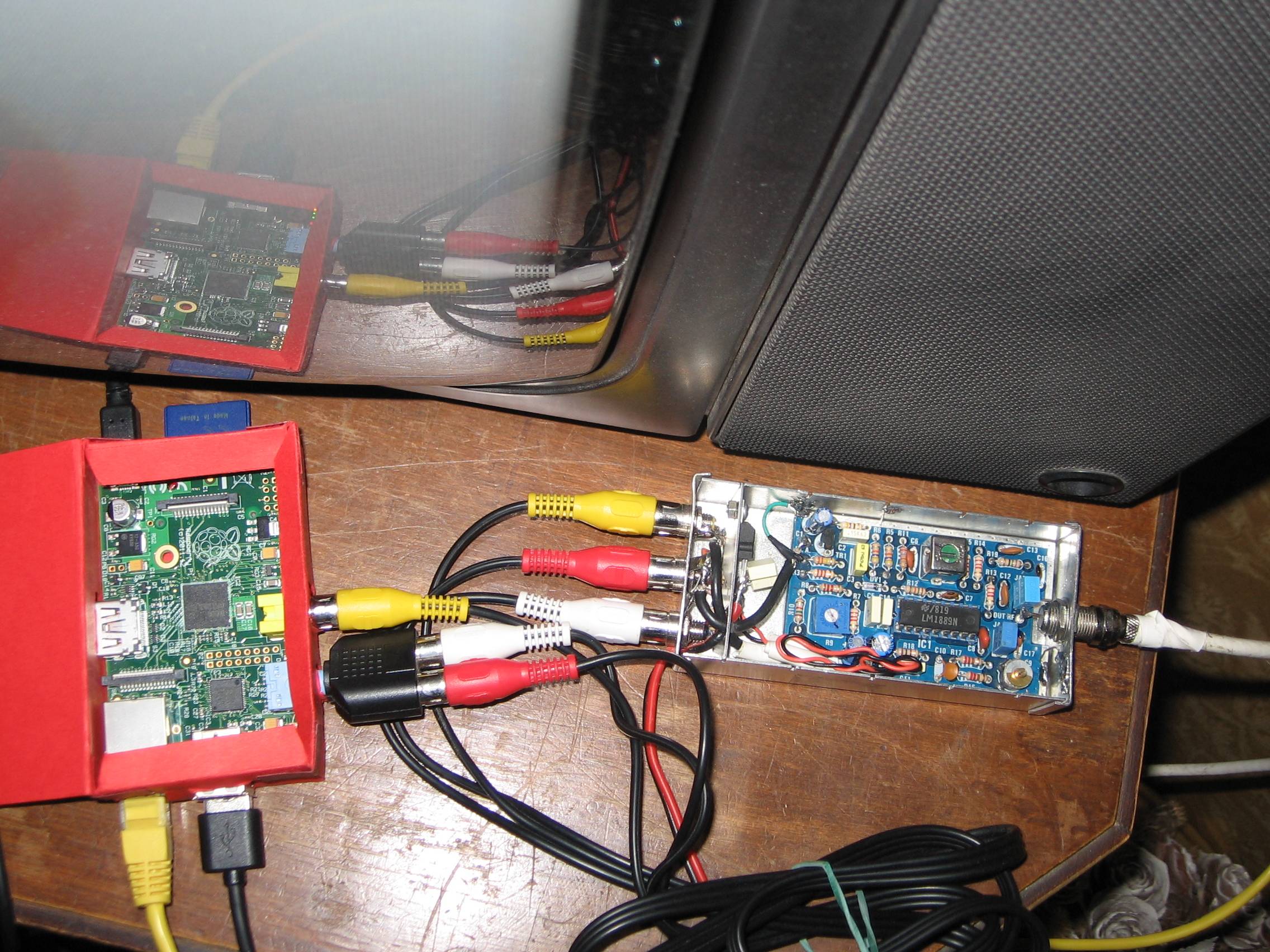

 hexed raft
hm yeah, so engineering whise this is fine, but I want to understand more about this transition,
what puzlles me is the modulation part, I kind of maybe understand it, making a sub conscious correlation to the pulse width modulation 🤔 ok I don't know anything
primal warren
It's actually simple amplitude modulation (AM). The carrier power is controlled by the modulating signal.