#help-with-radio
1 messages · Page 7 of 1
 normal drift
 rose mountain
What’s the center pin ?
normal drift
If you unscrew the TTGO antenna -look at the pin inside.
rose mountain
Ok I’ll check now
normal drift
same for the Pi -- where the antenna connects to the wire.
rose mountain
normal drift
same for the Pi -- where the antenna connects to the wire.
Looks good on both of them
The fact that around the pi there was 2 or 3 wifi antennas could impact the performance ?
 primal warren
Yeah, other signals can mask reception in many circumstances
normal drift
WiFi is way out the 868MHz frequency range so I would not expect it to be a big problem. Do you have more than one antenna, Cay you try a different one?
normal drift
primal warren
Yeah, other signals can mask reception in many circumstances
True, but still, 80m is pretty bad....
Is it intermittent or does nothing get through?
primal warren
Yeah, that's more like having a cellular antenna nearby
rose mountain
normal drift
WiFi is way out the 868MHz frequency range so I would not expect it to be a big ...
Yes I can try with an other one similar as the one on the TTGO, what should I try ? Change the one from the TTGO by the other one ?
normal drift
Your pick -- You'll really need to try all combinations to know. Only change one at a time 😉
rose mountain
Ok 👌
normal drift
Yus hould be able to use the TTGO antenna on the Pi -- as long as the connector is the same.
rose mountain
Do you have suggestions about antenna or the one above for TTGO and Pi should be ok ?
rose mountain
normal drift
Yus hould be able to use the TTGO antenna on the Pi -- as long as the connector ...
Yes it’s the same
normal drift
I am not as skeptical as @primal warren about the Amazon antenna but I really can't offer any opinion about the quality.
rose mountain
Do you have any link about a qualitative antenna ? It’s for commercial use so the most important is the performance
 green oracle
rose mountain
Do you have any link about a qualitative antenna ? It’s for commercial use so th...
green oracle
rose mountain
Do you have any link about a qualitative antenna ? It’s for commercial use so th...
For commercial use the most important is legal compliance.
normal drift
The antenna on my TTGO is the opposite type (plug vs socket) as the one I have on my pi. Be careful!
rose mountain
green oracle
For commercial use the most important is legal compliance.
Yes of course, I never said the opposite
rose mountain
normal drift
The antenna on my TTGO is the opposite type (plug vs socket) as the one I have o...
I checked it’s okay 👍
normal drift
I don't do commercial work -- I just play with my toys 😉
rose mountain
The biggest part of my time it’s also about playing with this type of toys !
Really impressed by LoRa btw
primal warren
When you say plug vs socket, are you referring to the difference between standard SMA and RP ("reverse polarity") SMA connectors?
normal drift
primal warren
When you say plug vs socket, are you referring to the difference between standar...
yes
primal warren
There are lots of well qualified antennæ available. DigiKey has a nice selection.
normal drift
For a commercial product, I would agree that someplace like DIgiKey is a much more reliable source.
rose mountain
Ok thanks
I’ll try switching antennas first and we’ll see
Oh I think I know !
There was this type of fence many times (5 or 6) between the pi and the TTGo

It’s metallic
primal warren
That would attenuate the signal greatly
normal drift
Raise it up!
normal drift
Hopefully that is the cause. It does make sense given the better response in your previous tests.
rose mountain
I have a picture of the plan, I’ll send it
If there is no fence between the two antennas but there still has one aside them, does the fence will attenuate the signal ? Or it has to be between them to attenuate it
normal drift
I would not expect it to be a problem if it is not in between them. RF transmission/reception is tricky. Elevation and line of sight makes it a lot easier.
normal drift
Nothing in the way. One antenna can "see" the other.
rose mountain
Ok, maybe I can use a long wired antenna to gain height
normal drift
Or a long coaxial cable connecting the antenna to the transmitter. The wire/antenna has to be tuned to the frequency.
I'm sorry, I have to go offline -- good luck!
rose mountain
normal drift
Or a long coaxial cable connecting the antenna to the transmitter. The wire/ant...
Yes I was talking about that !
Np thanks a lot!
normal drift
@rose mountain I think I should add that my RF experience is limited to some ham radio activity 20 years ago and recently playing with the RFM9X modules. There are many people around this discord that can give you much better advice, especially @primal warren. For a commercial application I am way outside my “comfort zone”.
rose mountain
no problem but your advices are really usefull !
 coral ermine
I was going to use this antenna for a project but it is discontinued, does anyone have any other options? (915MHz)
https://www.amazon.com/FrSky-900MHz-Performance-Antenna-915MHz/dp/B07R1XDQH8?ref_=ast_sto_dp&th=1

FrSky Zipp 9 900MHz High Performance Moxon Antenna (915MHz)
primal warren
They're in stock at the original link I posted (I don't buy anything from amazon)
coral ermine
primal warren
They're in stock at the original link I posted (I don't buy anything from amazon...
would something like this work for onboard the rocket?
https://www.sparkfun.com/products/14875

A small 1/4 wave rubber duck antenna for LoRa or other 860-960MHz communication. Antenna has a center frequency of 915MHz and utilizes an RP-SMA connector.
primal warren
I suspect it's not an omnidirectional antenna, presumably most of the signal comes from the sides, so if you had a way to mount it horizontally (tricky in a rocket), it would likely work well
coral ermine
primal warren
I suspect it's not an omnidirectional antenna, presumably most of the signal com...
what antenna should i use to be mounted vertically?
rose mountain
Do we have to keep the antenna vertical ? Or is there any specification about the way to place them ?
normal drift
rose mountain
Do we have to keep the antenna vertical ? Or is there any specification about th...
My understanding is that it is best to have them aligned in the same direction and as was mentioned yesterday, most of the energy from this type of antenna goes out the sides, so vertical orientation will likely be best for horizontal distance.
primal warren
The alignment also affects the polarization, so it's useful to have both antennæ aligned the same way. If you can't do that, and you want to avoid maximum polarization loss, you can use a "circularly polarized" antenna at one end, which imposes a fixed loss instead one that varies with polarization (this is often done in satellite communications when the satellite orientation is not fixed)
primal warren
coral ermine
what antenna should i use to be mounted vertically?
You'd want some sort of end firing antenna, possibly a helical design. Note that it will work well when the rocket is vertical, but when the rocket tips (which often happens at apogee before the parachute opens), you'll lose signal strength
Some discussion here https://www.rocketryforum.com/threads/900-mhz-homemade-antenna.179463/
Rocketry Forum - Model Rocketry Forums
I am trying to develop antenna for telemetry module to communicate long distance(20km) on rockets.
Antenna shape I want to develop:
900mhz 3dbi Helix normal mode antenna.
For the telemetry module, which receives and transmits signals horizontally, I want to make an antenna whose wire is wound in...
coral ermine
primal warren
You'd want some sort of end firing antenna, possibly a helical design. Note tha...
can i use this onboard it?
https://www.horusrc.com/en/frsky-r9m-lite-module.html
 primal warren
It seems to me like it ought to work, but I don't know a lot about that particular module
coral ermine
alight, thanks for the help!
primal warren
Where you expecting it to talk to a LoRa module or do you have some R9 gear to talk to it?
coral ermine
primal warren
Where you expecting it to talk to a LoRa module or do you have some R9 gear to t...
it will comnicate with the LoRa mdule on the https://www.adafruit.com/product/5714

This is the Adafruit Feather RP2040 RF95 LoRa Radio. We call these RadioFruits, our take on a microcontroller with a "Long Range (LoRa)" packet radio ...
primal warren
Ah, I didn't realize that. I thought it might use its own protocol.
normal drift
hmm -- I'm curious, where in the R9M documentation do you find that it will be compatible with an RFM95?
coral ermine
I think it talks about it in the description.
normal drift
I does look from this https://www.rcgroups.com/forums/showthread.php?3507725-Reverse-engineering-the-R9M-protocol-for-DIY-Multiprotocol like the R9M (at least the one discussed) uses the SX1276 module so it may well be possible to communicate with an RFM95 but it may not be easy....good luck!
 grim shore
Does anyone have a clue how to use the adafruit RFM69HCW with a raspi zero w running rasbian
I am new to this sort of thing and cant get it to work
normal drift
grim shore
Does anyone have a clue how to use the adafruit RFM69HCW with a raspi zero w run...
What RFM69 board do you have, What version of RaspiOS are you running? What have you tried? What doesn't work?
I have an RFM69 Bonnet running on a Pi zeroW with Bookworm now. You should be able to get it to work.
grim shore
I have the adafruit RFM69HCW 433MHZ as seen here https://thepihut.com/products/adafruit-rfm69hcw-transceiver-radio-breakout-433-mhz

The Pi Hut
"You see, wire telegraph is a kind of a very, very long cat. You pull his tail in New York and his head is meowing in Los Angeles. Do you understand this? And radio operates exactly the same way: you send signals here, they receive them there. The only difference is that there is no cat."Sending data over long distance
grim shore
normal drift
What RFM69 board do you have, What version of RaspiOS are you running? What have...
how do I check the current version of raspiOS
i have tried multiple different manuals written by adafruit
currently i am recieving this error with this code
import board
import busio
import digitalio
spi = busio.SPI(board.SCK, MOSI=board.MOSI, MISO=board.MISO)
cs = digitalio.DigitalInOut(board.CE1)
reset = digitalio.DigitalInOut(board.D25)
import adafruit_rfm69
rfm69 = adafruit_rfm69.RFM69(spi, cs, reset, 433.0)
Traceback (most recent call last):
File "/home/nedva/rfm69check.py", line 8, in <module>
rfm69 = adafruitrfm69.RFM69(spi, cs, reset, 433.0)
File "/home/nedva/.local/lib/python3.9/site-packages/adafruit_rfm69.py", line 316, in __init
raise RuntimeError("Invalid RFM69 version, check wiring!")
RuntimeError: Invalid RFM69 version, check wiring!
(program exited with code: 1)
Press return to continue
normal drift
Can you post a picture of your wiring. That error is almost always due to a wiring issue.
normal drift
also describe it -- what pins are connected. How are the connections made? Are the Header pins soldered to the boards?
I have to go offline for an hour or so - my wife and my dog are both asking me to go for a walk 🙂 Post a description of the wiring and a picture if you can. I'll look at it when I get back or perhaps someone else can help.


 grim shore
normal drift
I have to go offline for an hour or so - my wife and my dog are both asking me t...
grim shore
normal drift
I have to go offline for an hour or so - my wife and my dog are both asking me t...
okay thank you
normal drift
grim shore
Just starting to look. Can you also list the connections you are intending to use.
It looks to me like the gray wire for RST is on GND on the Pi and not on D25.
Also the GND pin on the RFM69 board looks like the solder did not flow well onto the pad. You might want to reheat that pin.
normal drift
grim shore
how do I check the current version of raspiOS
cat /etc/os-release
but it looks like your code is running OK so I don't think there is any issue with RaspiOS
grim shore
normal drift
Just starting to look. Can you also list the connections you are intending to us...
as in the other parts or the instructions i followed?
grim shore
normal drift
It looks to me like the gray wire for RST is on GND on the Pi and not on D25.
which is the D25 ?
?
grim shore
The comprehensive add-on boards & GPIO Pinout guide for the Raspberry Pi
does this work?
its what ive been referencing
normal drift
sure - that is fine -- It isa hard to see, but it looks like your RST wire is off by one.
grim shore
ive just moved it
let me try the code again
oh my god
it works
thank you so much
grim shore
thank you
normal drift
BTW -- In your picture, the Antenna is not attached. You should not run it without an antenna.
It is not good for the RFM module to transmit without an antenna
normal drift
Did you solve that problem?
grim shore
Not yet
normal drift
post the code you are running
grim shore
import board
import busio
import digitalio
spi = busio.SPI(board.SCK, MOSI=board.MOSI, MISO=board.MISO)
cs = digitalio.DigitalInOut(board.CE1)
reset = digitalio.DigitalInOut(board.D25)
import adafruit_rfm69
rfm69 = adafruit_rfm69.RFM69(spi, cs, reset, 433.0)

rfm69.send('Hello world!')
It clearly isnt as simple as i thought
ill have to read the documentation
normal drift
rfm69.send(bytes('Hello world!','utf-8'))
grim shore
perfect
normal drift
the payload has to be of type "bytes"
normal drift
You're welcome -- there are examples here https://github.com/adafruit/Adafruit_CircuitPython_RFM69/tree/main/examples
How fast do you want to send them? You have to send one packet at a time -- see https://github.com/adafruit/Adafruit_CircuitPython_RFM69/blob/main/examples/rfm69_transmit.py
grim shore
I am intending on sending around 1 string per 3 seconds
its just atmospheric data and gps coordinates
normal drift
Your receiver may be a bigger limitation than your transmitter. 1 packet every 3 sec sould be OK
grim shore
The reciever is an identical model with a large antenna attached
normal drift
That should not be a problem.
There are many parameters that you can "tweak", like the receive timeout. You may have to do some experimentation to find out what works best for you. Ask questions if you run into problems.
normal drift
@edgy folio FYI -- there is a lot of information about Amazon Sidewalk in this document https://docs.sidewalk.amazon/assets/pdf/Amazon_Sidewalk_Specification-1.0-rev-A.1-020824.pdf -- especially section 5.1.4. It appears that is uses both FSK and LoRa.
It is not at all clear to me why these packets should be regularly received by your RFM9x unless it was specifically configured to do so. They don't specify the actual frequency used. At least not that I have found...yet.
 edgy folio
Yeah it's even more complicated than I thought. Something like ascii/bin/hex/sha256/AES.
Brute forcing base64 and MD5 was fun but I literally have 1000 better things to do with my time than waste it on trying to crack a custom iteration of SHA256, SHA512, DES/AES/etc...
normal drift
I'm not so much intersted in decoding it as understanding why you see it at all...
edgy folio
🤷 I'd like to know that too but I might not get that clue unless I crack it. At this point it's just goint to have to remain a mystery. Maybe someone with more experience working with modern encryption could take a shot at it.
normal drift
I wish I could reproduce it... no luck so far.
edgy folio
I can only have my suspicions and spectulation that it's Sidewalk. It would make the most sense. The way things are going these days it could be coming from anything.
normal drift
True.. no shortage of RF devices in the wild 😉
 remote pond
yeah you’re not going to crack AES or any modern cryptography. implementation flaws, on the other hand, happen all the time
edgy folio
I don't believe that any encryption is uncrackable. Just depends on how much time and resources you want to dedicate to solving the puzzle. I'm not that interested.
As soon as I read RSA and AES in Sidewalk's pdf I was like yeah I'm good nvm.
remote pond
breaking encryption in practice is almost always done by going around the actual cryptography
design flaws that leak key material or provide insufficient randomness are classics
edgy folio
remote pond
breaking encryption in practice is almost always done by going around the actual...
Such as throwing all my Sidewalk devices in the garbage. Problem solved.
remote pond
edgy folio
Such as throwing all my Sidewalk devices in the garbage. Problem solved.
what had you been doing with Sidewalk?
edgy folio
Amazon echo devices (I highly suspect but not proven) are triggering my RFM mail boombox about 500 times a day on an open frequency. If I set an RFM node that solves it but that still doesn't negate the fact that Amazon devices can completely flood the 900Mhz public band.
remote pond
yeah spectrum pollution is definitely a thing, unfortunately
normal drift
edgy folio
Amazon echo devices (I highly suspect but not proven) are triggering my RFM mail...
To be fair, I still think it remains to be proven what the source of your interference is. So far, it does not make sense to me that you should be seeing the SideWalk packets on your RFM9x
edgy folio
It’s a guess. Could also be from new led workshop lights or the wireless toy T-Rex. 😅.
normal drift
Endpoints working in SubG-FSK mode shall be synchronized with a Gateway before an uplink or downlink transmission is performed. The synchronization mechanism works by searching for a periodic frame sent by Gateways, namely Beacon frames. Endpoints shall detect eligible Gateways by searching and receiving Beacons. In addition to its role in synchronization, Beacon payload carries basic information about the state of the Gateway, such as the Gateway’s cloud connection status, hopping seed or sequence number. The Beacon payload is not encrypted, allowing discovery and connection initiation by all Amazon Sidewalk devices. For a detailed description of the Beacon frame format and information carried by the Beacon, see Section 5.1.3.1. Section 5.2.1 describes the Beacon discovery mechanism that Endpoints use in initial synchronization with a Gateway.
``` interesting. this indicates that the beacon is not encrypted.But this is FSK, not LoRa
remote pond
LoRa is spread spectrum, right? should make it somewhat more immune to interference
normal drift
Yes, That is why I am so puzzled by the interference being seen.
remote pond
i guess if it’s same modulation and same frequency, you’re going to need a protocol-level way to reject unwanted traffic. and/or use directional antennas, if your transmitters are in fixed locations
 young cove
I'm surprised you are triggering on these packets. Isn't the data content not you what you are expecting/
normal drift
remote pond
i guess if it’s same modulation and same frequency, you’re going to need a proto...
Yes -- enabling node addressing takes care of rejecting most unwanted packets for LoRa.. For FSK, the sync word should take care of it.
 open kelp
Hey. I recently started a project with a mini diy ESP32 C3 board. The ESP, i2c EEPROM and everything else works fine but i cant get the WiFi Connection to work, and i don't really know where to start debugging, i don't have any oscilloscope or other fancy measuring equipment.
The PCB has to be as small as possible, so tolerances are tight but i tried my best following them.
Its a 4 layer PCB (0.8mm Thick) 0.5oz inner copper 1oz outer copper.
There is a ground plane underneath the antenna capacitors and inductor but not under the antenna (1. Pic).
The code is my standard WiFi/MQTT Test code, which normally works: https://pastebin.com/dLaCfLJg
The ESP Gets to the setup_wifi() function but stays in the while loop.
I tried swapping the antenna with one of an bought esp32 c3 board but it didn't work. My antenna worked on the bought board tho.
Pastebin
Pastebin.com is the number one paste tool since 2002. Pastebin is a website where you can store text online for a set period of time.


I've also done impedance calculations and it should be fine
 open kelp
I just saw this little white dot on the inductor. Does it have a polarity?
If yes which way does it go on? It's a LQP03TN2N5C02D
 fallow plank
RTL8720DN eRPC CircuitPython development
primal warren
open kelp
I just saw this little white dot on the inductor. Does it have a polarity?
 kindred vine
HI,
does RSSI change with Tx power change, I have set the TX_Power to 23 and then set it to 5 and ED and GW where in the same place as before but I don't see any difference in the RSSI. I a not able to understand.
primal warren
It can, but it's fairly loose. Additionally, the transmitter itself might be throttled by SWR so its effective power isn't really changing, or the receiver could be overloaded, or there could be interference, intermodulation distortion, limiting, multipath, etc.
open kelp
primal warren
https://article.murata.com/en-us/article/basic-facts-about-inductors-lesson-6
Finally had time and tried both orientations but nether worked.
Here is the full Repo
https://github.com/JacTech/Pointering
GitHub
A Smarthome controlling Ring. Contribute to JacTech/Pointering development by creating an account on GitHub.
remote pond
<@&327289013561982976>
 plain grotto
remote pond
<@&327289013561982976>
plain grotto
remote pond
<@&327289013561982976>
thank you
remote pond
thought the discord server link filter would have automodded that
plain grotto
remote pond
thought the discord server link filter would have automodded that
something strange appears to have happened in this instance. Several copies of the exact same message were blocked by the same user around the same time. We're unsure why this one got through.
 fading lynx
theoretically would having a wifi network that has passwords which continuously change and update be more secure than the current wifi state. (assume that the devices connected would always stay connected even when pwd changes)
or is there something im missing, i have done some research and yes there is more than jsut the pwd that keeps wifi secure but from what ive found that seems to be the main thing. and for example the way people strengthen their wifi security is by just putting longer pwds
 umbral oxide
@fading lynx That's a complicated question. It depends a lot on who and / or what you want to secure against (threat model). There are different authentication modes for wifi, and those have different security aspects. You may find that the process of frequently changing passwords has a higher likelihood of exposing them through other means. I'm also not sure if you can change the password on-the-fly and keep stations authed and associated. First order of business is to use equipment from reputable vendors, use the best auth mode supported by your AP and stations, and then to use a strong password that isn't shared with untrusted people or devices.
rose mountain
Hello,
I’m currently using the LoRa protocol on 868Mhz.
It looks like sometimes the TTGO automatically restart after catching a packet. But if we put the antenna far away with a wire we don’t have this issue (90% sure)
Is there something like radioelectric interferences ?
We’re not sure that the issue is after catching a packet, but it only appears after receiving a packet and « power up » a pin.
Thanks !
 vocal shell
hello! I am trying to get the LoRa rfm95x radio hat to work on my rpi zero 2 w and it is not being detected by the i2c interface. the board worked fine before on my rpi zero 1... i am not sure what to do
primal warren
I'd start with an I2C scan to see if anything is recognized
normal drift
vocal shell
hello! I am trying to get the LoRa rfm95x radio hat to work on my rpi zero 2 w a...
There should be no difference. What has changed? Are you using the same version of RaspiOS? Which one? What code are you running to test the radio? Were there any "customizations" of the jumper settings on the radio board. Is this the board you are using? https://www.adafruit.com/product/4074
Actually, the I2C interface is only for the display, not for the radio. How is the board connected to the Pi?
vocal shell
@normal drift yep that's the board. Rpi zero 2 w on Debian bookworm arm64. Literally did a full-upgrade last night. Board is connected via GPIO header. No customizations or jumpers.
I'm following this guide just like I did before and running the rfm95x_check.py script

Adafruit Learning System
Add low-power long-range radio communication to your Raspberry Pi Project
normal drift
vocal shell
<@343570430042308609> yep that's the board. Rpi zero 2 w on Debian bookworm arm6...
You did install blinka and enable the I2C and SPI interfaces?
vocal shell
normal drift
You did install blinka and enable the I2C and SPI interfaces?
Sure did. Raspi-config and all that
normal drift
Hmm. Only thing I can suggest is to unplug it and reconnect. Check for any bent pins.
Then try just initializing the radio just to see if SPI is working.
vocal shell
Yeah I may just reimage (again ugh) and start all over.
normal drift
Good luck. I have several working on pi zero 2ws. It should work!
vocal shell
Thank you for responding! I will check back in a couple days and let you know if it ends up working.
 wide basalt
@vocal shell Silly question, but you have enabled the i2c bus on the GPIO header, yes? It's not enabled by default. edit: Disregard, I see this was already asked. 🙂
normal drift
vocal shell
Thank you for responding! I will check back in a couple days and let you know if...
FYI -- I ran i2cdetect on mine ... ```(blinka_venv) jerryneedell@gjnpilora:~/projects/rfm9x $ i2cdetect -y 1
0 1 2 3 4 5 6 7 8 9 a b c d e f
00: -- -- -- -- -- -- -- --
10: -- -- -- -- -- -- -- -- -- -- -- -- -- -- -- --
20: -- -- -- -- -- -- -- -- -- -- -- -- -- -- -- --
30: -- -- -- -- -- -- -- -- -- -- -- -- 3c -- -- --
40: -- -- -- -- -- -- -- -- -- -- -- -- -- -- -- --
50: -- -- -- -- -- -- -- -- -- -- -- -- -- -- -- --
60: -- -- -- -- -- -- -- -- -- -- -- -- -- -- -- --
70: -- -- -- -- -- -- -- --
well i dont know what was wrong but i fixed it!

new problem. the board thinks buttons A and B are constantly being pressed
Sending signals too. Not sure why this is happening
 wide basalt
@vocal shell never ends, huh? I have some ESP32c3+SX1262 units en route.. What cool stuff are you planning on doing with that setup (once you get it all working)?
vocal shell
im trying to get it to work with meshtastic. some of the peeps in the meshtastic server have mentioned its possible so im trying to work it out for myself. definitely bleeding edge stuff
wide basalt
I have a Heltec LoRa v3 running meshtastic upstairs.. Just waiting for the day someone else sets up a node near me 😛
vocal shell
ive got 3 t beams i use for atak and some heltec ones. theres a super sick case on printables i am going to print for it
wide basalt
https://www.thingiverse.com/thing:6397478 i did that one

Thingiverse
Minimal housing for a Heltec V3 Meshtastic node.
The mounting and buttons are integrated into the case front.
Printed parts:
Case Front
Case Back
Purchased parts:
Heltec V3 https://www.amazon.com/dp/B086ZFCV7F
GT-U7 GPS https://www.amazon.com/dp/B084MK8BS2
103450 1800mA battery https://www.amazon.com/dp/B0BJPQXVZP
SS12F15 switch https://www.amaz...
vocal shell

Printables.com
Premium case for the Heltec V3 Lora board. Install the buttons, board and snap the 2 halves of the case together. | Download free 3D printable STL models
wide basalt
Nice lookin. No room for GPS, but many applications for meshtastic don't need one
vocal shell
nothing a little onshape tinkercad cant fix
normal drift
vocal shell
Sending signals too. Not sure why this is happening
Can you post the code you are running? If it is the code from the guide - then if a button is pressed, it will transmit a packet. I don't know why yours is detecting button presses. You should just run a test to see if the buttons are working.
Just to make sure, is the header on the Pi soldered in place? can you show a picture of the soldering.
It appears to be in a case, are you sure the case top is not pressing the buttons?
vocal shell
I'm running the default code from the web page. I even tried flipping the logic if not buttonA.value -> if buttonA.value and that didn't do anything. It's only buttons A and B that are doing it. Button C is working fine. The headers are soldered on, let me get a picture.
Yes im sure the case is not pressing the buttons. In the pic with the flipper, the case top is open and it's still transmitting
normal drift
It sounds like, for some reason, buttons A and B are grounded so always triggering. Can you try just testing the buttons manually via Python or a simple script. If they are not working, it may be an issue with the board. If so, I would suggest posting to the support forums https://forums.adafruit.com/viewforum.php?f=19 if we or someone else can't find a solution.
If you have a multimeter, you can test if the buttons are functional.
vocal shell
I will check for shorts and see if I messed up my soldering somewhere. I have some press fit headers coming in tomorrow so I might try and change it out
normal drift
Good luck -- I would create a simple button test just to diagnose this. The radio and display seems to be working OK. It will be easier to test one thing at a time. Also since you said you modified the code to switch the logic at some pint, double check that you put it back to the if not button.value These are definitely active low! Pressing the button will ground the Pin it is connected to.
vocal shell
Don't worry i made a copy of the file before I started changing stuff.
 thorny sky
Hi all 🙂
I am planning to create a sensor module which has RF capability to stream information in real-time to a base station. As I never have done any RF related PCB design I was asking myself if it is better to have a longer Rf trace on the PCB to the edge of the board or use a UFL/MMCX to SMA pigtail adapter? Any help is greatly appreciated 😉
wide basalt
Depends on your requirements. A pigtail to sma will allow you to attach antennae of various gains for different applications, and will allow for better range overall. A PCB trace antenna will take up less room, have fewer parts, but will have a single antenna option and reduced range over a good external antenna.
thorny sky
Thanks for the quick answer. I think I may have made myself not clear enough 😄 I wanted to know the difference between a long segment of 50 ohm impedance trace on the PCB to a SMA connector at the edge of the board and a pigtail. I do not want to use a PCB antenna 😉
primal warren
I'd probably opt for the SMA connector, not because of performance differences, but mechanical strength. The U.FL connectors are delicate, getting an connector removal tool* is recommended, and they only support a limited number of mate/demate cycles.
- Getting the tool isn't difficult or expensive, but in my experience, finding it when I need it can be frustrating
 sharp tiger
Great day everyone. I’m putting together a kit building classes with a local ham radio club. Looking at doing projects with the pico or other rp2040 processors. Trying to focus on sdr or loran related topics. Each session will be for 2.5 hours and would like to do a completed project per session. Each session will be theory circuit then building. Would like projects that would fit on a breadboard so no or limited soldering meaning no smd only through hole. The next level classes will be designed for more complex circuits and smd/through hole soldering. I saw some basic sdr circuts but looking for any suggestions. Class structure would be circuit theory /circuit build/operation of project then when class is over pass out a shopping list for the next class. Once again this is for a well established and active ham radio club but no kit building etc to excite new members. Any thoughts are welcome
primal warren
SDR is pretty modular, so you'd presumably just put a Pico and an SDR module on a breadboard and hook them together with SPI or somesuch, and then run antenna leads to the SDR. This doesn't get into circuit theory at all, but does avoid the issues of trying to run RF through a breadboard
sharp tiger
No not at all. Plenty of examples of transmitting receiving without using an sdr module.
young cove
sharp tiger
Great day everyone. I’m putting together a kit building classes with a local ha...
Are these of interest? https://www.adafruit.com/product/5712
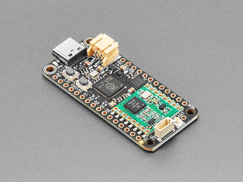
This is the Adafruit Feather RP2040 RFM69 Packet Radio (868 or 915 MHz). We call these RadioFruits, our take on an microcontroller with packet radio transceiver ...
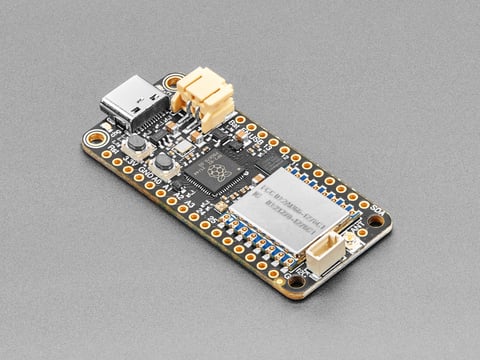
This is the Adafruit Feather RP2040 RF95 LoRa Radio. We call these RadioFruits, our take on a microcontroller with a "Long Range (LoRa)" packet radio ...
5714 is currently out of stock. These are easily programmable in CircuitPython or Arduino.
for simple rx/tx: https://www.adafruit.com/product/5640

Never hunt around for another crystal again, with the Si5351A clock generator breakout from Adafruit! This chip has a precision 25MHz crystal reference and internal PLL and dividers so it ...
Si5351A output is 11dBm, could easily drive a diode ring mixer: https://groups.io/g/qrptech/topic/si5351_output_power/68766599?p= which points to https://miscdotgeek.com/building-a-direct-conversion-receiver-part-4/ as well
this is an extremely common RF clock generator as you know, often used in SDR (and TX) applications
sharp tiger
@young cove Thank you very much this is extremely helpful…..
open kelp
Hey. I created a DIY ESP32 C3 Board with a WiFi chip antenna. Till now i haven't managed to get it to work, so i ordered a VNA and am now trying to figure things out. Since i know nothing about VNA's i use this video as a tutorial, however in munite 6:35 the reference plane gets set to the VNA's connector and he just adds 700ps E-Delay for his cable. How do i get that value for my cable? https://www.youtube.com/watch?v=rbXq0ZwjETo&t=421s

PCB antennas are pretty common because they are small and cheap. Can we use them for our projects? How do they work? And: How can we test and tune them? Let’s look at an antenna for the 868-915MHz ISM bands. As a side-effect, you will learn how to measure impedances directly on a PCB.
Links:
LiteVNA (Currently best "NanoVNA"): https://s.click.a...
primal warren
open kelp
Hey. I created a DIY ESP32 C3 Board with a WiFi chip antenna. Till now i haven't...
Basically, you'd look up the propagation velocity for your cable, then calculate the length required by dividing the speed of light by the delay you want, and scaling by the propagation velocity
So if your cable is RG-58, it has a propagation velocity of 0.66, so 140mm of it would give a delay of 709ps.
open kelp
so for a RG316 cable with a propagation velocity of 0.69 and 15cm length it would be 699.99ps
primal warren
Seems right to me
open kelp
primal warren
Seems right to me
Alr. Thanks. Also funny thing, when i soldered on the coax cable the esp studently had a perfect wifi connection with just the cable as an antenna.
primal warren
At that wavelength, most any piece of wire would make a fair antenna
 orchid narwhal
Hi friends, I'm working on a hat for a Raspberry Pi Pico W, that includes a few sensors, and a RFM69 module. I want to use a board antenna connector like this one https://www.digikey.com/en/products/detail/molex/0732511153/11305709. Do I need to worry about anything special for the trace between the RFM69 Antenna pin, and the antenna? I tried to keep it as short as possible, and wide.

Anything else I should watch out for?
open kelp
primal warren
At that wavelength, most any piece of wire would make a fair antenna
Well accept for the antenna im trying to use. even with a VNA i cant get it to work
young cove
open kelp
Well accept for the antenna im trying to use. even with a VNA i cant get it to w...
if the chip antenna is not working at all I would suspect some very basic issue like a wiring error or bad or incorrect components. The chip antenna datasheet probably has a sample configuration.
open kelp
The chip antenna itself works fine (tested on a esp32 c3 mini board) i just couldn't really comply with the clearances, i thought it should still work (perhaps a bit worse but i don't need crazy range, just in my room) if i chip away view mm here and there.
this is how the 4 layer board looks like btw
 young cove
open kelp
The chip antenna itself works fine (tested on a esp32 c3 mini board) i just coul...
young cove
open kelp
The chip antenna itself works fine (tested on a esp32 c3 mini board) i just coul...
The keepaway clearances were spec'd for a reason. there are no traces underneath, right? you checked that the matching components are correct, right? I don't know how much less clearance you have than is recommended. If there is an issue with the layout or the components, then no RF may be getting to the antenna or it may be very badly matched
open kelp
young cove
The keepaway clearances were spec'd for a reason. there are no traces underneath...
- No traces underneath the antenna, 2 solder pads (USB D+ and D-) underneath the feedline but with 2 layers of ground between
- I tried my best at getting the impedance to the center of the smith chart in the pic you can see the best i got with my limited knowledge
- The recommended clearance in the datasheet is 8x3mm, I've got 7.8x2.6mm
- There should be no issue with the layout and RF is getting to the antenna, cause i got a WiFi connection, when soldering on the coax cable
- But it could just be badly matched, i just soldered on different capacitors/inductors and resistors and looked what got me closest to the center.
 young cove
open kelp
- No traces underneath the antenna, 2 solder pads (USB D+ and D-) underneath the...
young cove
open kelp
- No traces underneath the antenna, 2 solder pads (USB D+ and D-) underneath the...
The cap and inductor should be computable given the info from the microcontroller and the chip antenna. The layout difference is not that terrible. But I haven't done this personally.
 median latch
(question I had while reading about digital-over-radio protocols) - it seems like IR protocols typically use a "base" on-off square wave (~38Khz) that's itself then on/off modulated to send messages, whereas most 433Mhz protocols seem to rely on just on-off keying the 433Mhz signal. Is the difference just that 433Mhz receivers are expected to filter the spectrum enough/there's much less noise to deal with/ compared with IR receivers?
primal warren
Yes, that's it: lots of things produce IR and lots of it, so you need to be able to distinguish the signal you're looking for even when it's swamped with something much stronger. There's not as much competition in the 433Mhz space.
 restive fjord
hi we are havign some trouble with the rfm69 radio, we are getting the error message : runtime error: invalid rfm69 version, check wiring! and some noites about line 11 of the radio code. we have checked this however and everything seems to be correct. does anyone have any ideas where this error couldl stem from? thank you :)
normal drift
restive fjord
hi we are havign some trouble with the rfm69 radio, we are getting the error mes...
It is almost always due to a wiring or pin assignment issue. What rfm69 board are you using, what MCU - how is it wired? A picture would be great. Can you post the code you are running?
restive fjord
normal drift
It is almost always due to a wiring or pin assignment issue. What rfm69 board ar...
weve checked all of our soldering wires and pin assignments
we are just using the rfm69, soldering it onto circuitboards. i can send a pic in a second
normal drift
Which rfm69 - the breakout? https://www.adafruit.com/product/3070
What microcontroller -- what code?
restive fjord
there are like lots of radios on there but the only one being usedis the wired one
the soldering is alright

soldering


this is the code, the problematic bit is line 11 but we cant seem to find anything wrong with it.
normal drift
It is really hard to verify the wiring. Have you verified every connection?
normal drift
I dont see the connections to GP2,3,4,6,7
restive fjord
MOSI is to gp3 and miso is to gp4
normal drift
I was disoriented, now I see, but it is very hard to follow.
restive fjord
yes it is, but the wires should all definitely be in the right places.
which means its to do with the code, most likely
we had it soldered by a quite experienced solderer.
normal drift
The connections to the pico from the wires look marginal to me.
The code you have should detect the board OK -- you will need some cahnges to actually use it, but one step at a time...
restive fjord
ah why not? we want to focus on troubleshooting more the code than the wiring
is there anything you would recommend to change the code to make it work?
normal drift
take a look at the example from the library https://github.com/adafruit/Adafruit_CircuitPython_RFM69/blob/main/examples/rfm69_simpletest.py
But if it does not detect the board, you are wasting your time.
restive fjord
it has definitely worked before though, we tried it with the lora radios.
i will visit the link thanks
ok ive checked it but its exactly the same.
from where we sourced the radio from, the person said it is an older chip. is that a problem?
do you think that could affect its ability to use the libraries?
normal drift
restive fjord
it has definitely worked before though, we tried it with the lora radios.
The conection to GP4 lookks suspicious to me.
normal drift
restive fjord
from where we sourced the radio from, the person said it is an older chip. is th...
It looks like the standard Adafruit breakout board to me.
I have used those boards many times with the CircuitPython library.
restive fjord
normal drift
It looks like the standard Adafruit breakout board to me.
if its an older chip though?
would that be visible? would you be able to tell?
restive fjord
normal drift
The conection to GP4 lookks suspicious to me.
noted thank you - we will check
normal drift
restive fjord
would that be visible? would you be able to tell?
I can't read the actual chip in the picture, but I am not aware of any changes to the chips used on the adafruit breakout boards. I doubt that is the problem. Mine are several years old.
young cove
i would suggest breadboarding this with jumpers to test if you have some spare identical RFM boards. You can test just with a pico and the RFM board
normal drift
This is very disconcerting...https://github.com/adafruit/Adafruit_CircuitPython_RFM69/issues/52 apparently there are some RFM69 boards with a different version ID. Has anyone else ever seen one? The reported issue is with a Feather RP2040 RFM69...
young cove
normal drift
This is very disconcerting...<https://github.com/adafruit/Adafruit_CircuitPython...
This is certainly confusing. I can ask internally tomw about this.
normal drift
young cove
This is certainly confusing. I can ask internally tomw about this.
Thanks for releasing the new version...
normal drift
restive fjord
noted thank you - we will check
AS you can see from the above comments, there is a possibility that you have a board with a different version ID. You may want to try the newly released version of the library - it is in the latest "bundle"
young cove
normal drift
Thanks for releasing the new version...
I'm glad this got figure out -- certainly confusing given that the previous reason for that error was always wiring
normal drift
Yes -- it will complicate future issues....
I noted that in the RAdioHead library they now just test for the ID not being 0x00 or 0xff....anything else is accepted.
young cove
maybe it should print out the ID that was read. Do the RFM9x have a different ID (if you use one by mistake)
normal drift
yes, rfm9x is different (0x12)
I'll add a printout of the id in the error message to my new library. Not sure we want to add code to the old one..
young cove
good point
normal drift
On the rfm9x the version is in a different register though so it will fail anyway.
 modern patio
Anyone who has worked with the "ESP32-S3 Feather with 4MB Flash 2MB PSRAM" (#5477) - how limited is the BLE? There is a pretty big warning on the page. Is it able to do Wifi and BLE both? Or is it liek the similarl CPU Airlift that requires hardware selection between Wifi and BLE?
young cove
modern patio
Anyone who has worked with the "ESP32-S3 Feather with 4MB Flash 2MB PSRAM" (#547...
It is limited right now as the warning indicates. A more complete implementation with proper service and peripheral capability is under active development.
There is no enough room in 4MB flash for OTA and BLE. We may not support BLE on 4MB boards, or remove OTA instead. We are discussing what to do.
modern patio
young cove
It is limited right now as the warning indicates. A more complete implementation...
I ttally understand. So using Adafruit parts, what is my best path to a resonably complete wifi/ble bridge? I find feather to be convenient, but I can certainly do stemma or breadboarding.
The Pico W? The RP2040 with an Airlift? The ESP32-S3? Each seams to have divergent limitations. Don't misunderstand, i totally get that Adafruit is more of a rapid moving company of options, not really geared to providing a production ready stack.. but I need to both move fast and pay some attentiont o eventual production :)(
The pico W looks promising, and the BLE seems enabled under Micropython, but the storage seems pretty anemic compared to the RP2040 feather.
young cove
modern patio
I ttally understand. So using Adafruit parts, what is my best path to a resonabl...
This is the main thing Scott is working on now We don't give expected dates, but it is really actively being developed. There is no other easy one-board wifi-BLE bridge. You could use an nRF52840 and some wifi-capable chip and have them talk to each other.
modern patio
Gotcha. Thanks!
modern patio
young cove
This is the main thing Scott is working on now We don't give expected dates, but...
I think I'm goign to experiment with the PicoW. I'll need to do some wiring to connect it to the rest of the stuff im using (which are all feather style boards) but the maturity of the BLE/Wifi stack is too good to ignore. If I wind up runnign out of memory (I shoudlnt, ots jsut a remote sensor pack) I'll need to re-think the system... but for now it will work to start
 shrewd vault
Could Lora be a good low cost ish way to create a pps output for indoor use due to lack of gps penetration?
remote pond
there’s WWV, etc (or your national equivalents)
primal warren
Or counting power line cycles (they may vary slightly over the day will but will average out to the correct value as they're widely used as a timekeeping reference)
 steady vapor
if you have access to any wifi signal, you could use even the lower level timestamps as a crude time source to generate a pulse signal
remote pond
or if your device has Bluetooth and will regularly connect to devices with current time service (CTS), that’s another way to sync (though not as precisely)
shrewd vault
Thanks for the suggestions. I can't find any OTS WWV modules, so that might work for me. Also, not connected to mains in any way, so can't do AC timing. If I did WiFi, I could do NTP, but that's a bit of heavy lifting for my Arduino. Lora looks to be the best option, FCC certified modules for under $10 and lots of Arduino library support. And gets me the range I need indoors, through walls at a 50-100m.
remote pond
huh, apparently the main supplier of WWVB receiver chips stopped making them, so people are scavenging them from used “atomic” clocks
primal warren
There seems to be a replacement chip (the CME8000), but it's apparently buggy.
remote pond
(i guess the VLF WWVB is more popular for appliances than the HF WWV due to better propagation indoors?)
 static juniper
Hi folks, using an ebyte LoRa module on a custom breakout PCB. Are there any obvious errors (besides the missing stitching vias)?
Im using a whip antenna, and dont know if those need to be in the middle of the board or not.
Also, should I route the SPI signals on an internal layer? I think these antennas need a good ground plane to work well.
 primal warren
You say you're using a whip antenna, but that looks like an end launch SMA connector footprint
static juniper
Yes, the antenna attatches to the SMA connector
I have no idea what I am doing, so I might have the terminology wrong
primal warren
For connectorized antennas like the ones that use an SMA connector, the antenna or its mounting provides the ground plane, so the PCB doesn't have to. Also mounting the antenna remotely helps avoid interference between the antenna and the circuitry.
rose mountain
Hi, I have problem with one of my RPI which is running a Lora process in python in background. Sometimes ssh connection are down and network too. I have: ssh connection reset by peer. I'm using Bullseye and RPI 3B+. Does it look familiar to one of you or do you think it's due to the lib that I'm using ?
primal warren
That sounds like either sshd is crashing or a network problem.
 strange tundra
I’m wondering if this is an appropriate place to ask this, but is anyone experienced with ham radio? I’ve been curious about it lately. Interested in starting but don’t fully understand the point of jumping in “casually”. I kinda see ham as just a fancy way of connecting with people across the world, and I’m an introvert. 😬
 pallid ruin
Ham radio made a lot more sense before the internet
primal warren
I find ham radio a way to tinker with stuff. There are lots of bands and modes, so if talking to people isn't your thing (I'm an introvert too), there's plenty to enjoy. I jumped in casually quite a while ago, got some cheap gear and played with it.
remote pond
if you get into contesting, propagation testing, etc, your interactions with other people can be highly scripted and non-social, if you want
young cove
strange tundra
I’m wondering if this is an appropriate place to ask this, but is anyone experie...
I was very impressed as a 12yo by the amazing ionosphere and how a weak signal could travel thousands of miles. I built a kit radio and did some shortwave listening. For various reasons I wasn't able to get a license then, but got one in grad school. I built a number of low-power radios and related test equipmentin the 1987-1993 range, then didn't do much, though I kept an antenna up. Recently I bought a new radio and starting doing FT8, which is a stylized digital mode, which I enjoy a lot.
remote pond
digital modes are great if you don't want to talk with other people by voice. (i guess Morse Code counts as a kind of digital, too)
strange tundra
remote pond
if you get into contesting, propagation testing, etc, your interactions with oth...
Cool! i'll have to look into this.
strange tundra
remote pond
digital modes are great if you don't want to talk with other people by voice. (i...
Downloaded a morse app today. Kinda fun!
Also these different "modes" make it feel like a game with different modes.
strange tundra
young cove
I was very impressed as a 12yo by the amazing ionosphere and how a weak signal c...
That's pretty neat! I asked pretty much the same question on reddit and got like 40 responses.. Can't wait to dig into them!
median latch
strange tundra
That's pretty neat! I asked pretty much the same question on reddit and got like...
What made you curious about ham radio btw? (ham here, tend to mostly play with building kits/listening satellites than contacts.)
strange tundra
median latch
What made you curious about ham radio btw? (ham here, tend to mostly play with b...
Most recently, probably a YouTube video on it or something. My first contact with it was in Boy Scouts, like 25 years ago. More recently, I bought a shortwave radio in hopes of hearing signals from far off places and sampling them for use in my synthesizers.
Going forward, I’m hoping to prepare for when the SHTF, and to see if it’s possible to somehow wire some form of ham radio into a modular synth, controlling the various parameters.
median latch
strange tundra
Most recently, probably a YouTube video on it or something. My first contact wit...
(If you haven't already looked it at) one thought is there's a lot of interesting listening with one of the inexpensive software defined dongles + a PC running some decoding software. That lets you listen in to a more diverse (and likely more interesting) range of communications compared to a shortwave radio and you might find a particular area that tickles your fancy.
strange tundra
median latch
(If you haven't already looked it at) one thought is there's a lot of interestin...
Yeah. I find myself drawn to POTA, the fr8 thing (cant remember the exact name), and the email thing. Basically anything that lets you send data packets. But I am curious about making contacts and listening too.
Trying to nail down a piece of gear. I’ve heard of the SDR dongles. I have a Mac, but also have parallels and windows. I tried Kiwi sdr, but so far can’t quite figure it out. I need to learn and get my first license first, but that might take a while.
I know I’ve been rambling, but I do have a message out to the local ham club. Hopefully I’ll hear back soon!
primal warren
There should be Mac software for a bunch of modes
 sacred crest
Poking my head into the discord for the first time in a while, coincidentally. I’m a ham - got my license back around 1991 or so and was active in my college’s radio club but then didn’t touch it for a few decades. Im getting back into it and starting with one of those digital modes. A friend got bit by the Pokemon Go (aka “stamp collecting”) aspect of the digital FT8 stuff - you have a fairly structured communication with the other station and then it’s over so it’s perfect for introverts. The stamp collecting/Pokemon Go part is having contacts with people in different geographical spots.
The FT8 stuff is made for low power so you can use a radio that fits in your pocket (the antenna, not so much). I’ve got a small radio and a raspi running the “wsjt-x” software. The software handles all the work - it cycles through the structured message stuff and plugs in the right numbers etc.
You do need accurate time on whatever’s running the software.
primal warren
Perfect for introverts? I feel seen...
 void jetty
I’d like to get radio on this microcontroller (MatrixPortal M4, https://learn.adafruit.com/adafruit-matrixportal-m4/pinouts) to have it receive messages from this feather (https://www.adafruit.com/product/5712)
It seems like I need to add RFM69 (https://www.adafruit.com/product/3070) to the M4. I don’t understand the pins that need to be connected though. I’m reading the two pinout diagrams but don’t know where to start to bring them together.
Any help or pointer to the right resource is appreciated. Thanks!

This is the Adafruit Feather RP2040 RFM69 Packet Radio (868 or 915 MHz). We call these RadioFruits, our take on an microcontroller with packet radio transceiver ...

"You see, wire telegraph is a kind of a very, very long cat. You pull his tail in New York and his head is meowing in Los Angeles. Do you understand this? And radio operates ...
primal warren
void jetty
I’d like to get radio on this microcontroller (MatrixPortal M4, https://learn.ad...
The product page has a link to the learn guide https://learn.adafruit.com/adafruit-rfm69hcw-and-rfm96-rfm95-rfm98-lora-packet-padio-breakouts/pinouts which explains the pinouts and connections. It's basically an SPI peripheral, so you hook power and the SPI bus pins (SCK, MISO, and MOSI), along with three other pins you can choose for chip select, reset, and interrupt.
open kelp
Hi. Im having troubles getting an NRF24L01 (mini) to work. for some reason radio.available() always returns true. I've read, that its related to power issues but i dont think thats the problem.
Here is my Code: https://pastebin.com/zTdmiuWL
And here a schematic of the whole PCB (EEPROM and LED works fine)

Pastebin
Pastebin.com is the number one paste tool since 2002. Pastebin is a website where you can store text online for a set period of time.
void jetty
primal warren
The product page has a link to the learn guide <https://learn.adafruit.com/adafr...
Thanks, I have access to these 11 pins
https://learn.adafruit.com/assets/111881
I see the 3.3v, GND, but dont understand if I need to connect the "EN" on the NRF to the M4.
And then I get further confused, I don't see these pins on the M4 so I don't figure out how they match.
SCK - This is the SPI Clock pin, its an input to the chip
MISO - this is the Microcontroller In Serial Out pin, for data sent from the radio to your processor, 3.3V logic level
MOSI - this is the Microcontroller Out Serial In pin, for data sent from your processor to the radio
CS - this is the Chip Select pin, drop it low to start an SPI transaction. Its an input to the chip
RST - this is the Reset pin for the radio. It's pulled high by default which is reset. Pull LOW to turn on the radio
G0 - the radio's "GPIO 0" pin, also known as the IRQ pin, used for interrupt request notification from the radio to the microcontroller, 3.3V logic level
void jetty
void jetty
Thanks, I have access to these 11 pins
https://learn.adafruit.com/assets/111881...
Ok I see them here after studying more, but I dont understand how they physically match up.
 umbral oxide
@void jetty unfortunately the SPI pins aren't exposed as pads or headers on the MatrixPortal M4, so it's hard to add a new SPI peripheral
it might be possible to use other pins for SPI (easier on Espressif chips than on M4)
from the pinout:
or SPI (SCk on pad 1, MOSI on pad 0 or 3, MISO on any pad remaining)
(see more info on SERCOMs here: https://learn.adafruit.com/using-atsamd21-sercom-to-add-more-spi-i2c-serial-ports
void jetty
As a hobbyist this is really complicated so I apologize as I try to keep up. What is a pad? Here is how far I am.
 umbral oxide
SERCOMs are complicated... it's been a while, but I think "pad" refers to the number after the decimal in the blue e.g. "S5.2" ("S5.2" is SERCOM 5, pad 2)
the connection of RST to RST will reset the radio when you hardware reset the MatrixPortal, but I think you want a GPOIO GPIO on the Matrix Portal to go to the radio RST so that software can reset the radio
void jetty
GPOIO? I'm sorry but I dont understand that, is it a pin I dont see it on the asset diagram
I'm trying to stop connecting these devices to wifi and having them communicate through a middleman webserver. Its been a very high barrier to entry to break that bad habit though.
umbral oxide
Yeah, GPIO (General Purpose Inout / Output) is just a pin you'll set up as a digital output on the MatrixPortal to issue a reset to the radio from software. Similar for the G0/IRQ and CS pins.
void jetty
Sounds good I can move it to RST (RFM69) to A4 (MatrixPortla M4), I dont see a path to connect these though (SCK, MISO, MOSI, CS). Is it impossible to connect these boards?
SCK - This is the SPI Clock pin, its an input to the chip
MISO - this is the Microcontroller In Serial Out pin, for data sent from the radio to your processor, 3.3V logic level
MOSI - this is the Microcontroller Out Serial In pin, for data sent from your processor to the radio
CS - this is the Chip Select pin, drop it low to start an SPI transaction. Its an input to the chip
RST - this is the Reset pin for the radio. It's pulled high by default which is reset. Pull LOW to turn on the radio (A4 on MatrixPortal)
G0 - the radio's "GPIO 0" pin, also known as the IRQ pin, used for interrupt request notification from the radio to the microcontroller, 3.3V logic level (A3 on MatrixPortal)
If only it was this easy 🙂 https://learn.adafruit.com/adafruit-rfm69hcw-and-rfm96-rfm95-rfm98-lora-packet-padio-breakouts/circuitpython-for-rfm69#wiring-with-breakout-2980448, I guess I'll move on. Thank you for helping me out.

Adafruit Learning System
Radio transceiver modules for long distance data communication
umbral oxide
Looking at the MatrixPortal pinout, the limited pins available that are on the same SERCOM (S0) are A1-A4.
or SPI (SCk on pad 1, MOSI on pad 0 or 3, MISO on any pad remaining)
So,SCKhas to be on pad 1, soSCKhas to be pinA1(S0.1).MOSIcan beA2orA4, let's go withA2.MISOcan use the remainingA3(S0.2).
This leavesA4forRST. I thinkCScan be anything, andG0/IRQcan be anything...RXandTXwould be the easiest (although potentially you could tap into the pins on the I2C or Analog connectors) ...this is a bit of a guess, check my work or try it out and see if it works.
void jetty
Thank you, I'll go for it.
young cove
void jetty
Thank you, I'll go for it.
Here's a program that tries all combinations of pins to find the ones that work for SPI. This is in the spirit of https://learn.adafruit.com/circuitpython-essentials/circuitpython-uart-serial#wheres-my-uart-2985036
 dense thorn
So I’ve made a really simple tx/rx pair of radio modules. They’re basically a walkie talkie pair. The current draw on the receiver is 16mAH, which is 5x higher than the receiver - which only does something if it sees a change on a hardware pin. Is 16mAH consumption sustainable for a wearable with a rechargeable battery? I think I can get 12hrs from a 400mah battery if I’m thinking correctly.
young cove
dense thorn
So I’ve made a really simple tx/rx pair of radio modules. They’re basically a wa...
400 mAh / 16 mA = 25 hours. But sounds practical
primal warren
The receiver draws 5x as much as the ... receiver?
 hard mulch
Hi. I'm working on a Adafruit ESP32-S3 project, setting up MQTT. I have had a TON of trouble getting it working. It would disconnect all the time, or not connect at all, usually complaining about socket errors or timeouts. I eventually decided to try a different internet wifi access point, so I switched from my home wifi access point to a mobile hotspot access point, and that fixed everything! Now all worked as expected.
Anyone have an idea how I could figure out why the ESP32-S3 didn't like my home internet access point?
 pale dagger
I think the short answer is "maybe, it's either easy or hard". Check for logs on the router or ESP32-S3 (what firmware is it running?). If there's something obvious, there you go. If it's not obvious, it's probably going to be hard to figure out, and may not be possible with regular consumer devices. You can also try basic troubleshooting stuff like upgrading firmware on the ESP32-S3, on the home router, and checking signal strength.
primal warren
Could be an issue with DHCP leases
pale dagger
If you move the ESP32 closer to the router, does it get better? If yes, then you might be dealing with signal strength and/or interference problems
hard mulch
Sorry, I had to leave the keyboard. Thank you for the suggestions. I'll look into the DHCP and try moving closer to the router.
 indigo aspen
I am using a feather m0 rfm96 lora 433mhz to build a lotek test tag. the test tag send out a pulse and then it waits a specific number of milliseconds then sends out another pulse terminate the first number and start the next number. a tag id uses four pulses with these measured gaps. I am using radiolib to program the radio and here is the function I am using. now it appears that the timing of the gaps are fluctuating. does anybody have any experience with tight time tolerances that can provide a suggestion?
void pulse(uint16_t dlen, uint16_t dlen1, uint16_t dlen2)
{
dlen = (dlen -2) * 1000 - 500; // - LOTEK_TIMING_DELAY
dlen1 = (dlen1 -2) * 1000 -500;
dlen2 = (dlen2 -2) * 1000 - 500;
__disable_irq();
int16_t state = radio.transmitDirect(); // lotekFreq);
delayMicroseconds(2000); // target 2.5ms 1300
// delay(10); // for testing with TinySA
radio.standby();
delayMicroseconds(dlen);
state = radio.transmitDirect(); // lotekFreq);
delayMicroseconds(2000); // target 2.5ms 1300
// delay(10); // for testing with TinySA
radio.standby();
delayMicroseconds(dlen1);
state = radio.transmitDirect(); // lotekFreq);
delayMicroseconds(2000); // target 2.5ms 1300
// delay(10); // for testing with TinySA
radio.standby();
delayMicroseconds(dlen2);
state = radio.transmitDirect(); // lotekFreq);
delayMicroseconds(2000); // target 2.5ms 1300
// delay(10); // for testing with TinySA
radio.standby();
__enable_irq();
if (state != RADIOLIB_ERR_NONE)
{
Serial.print("TX failed, code ");
Serial.println(state);
}
}
void jetty
umbral oxide
Looking at the MatrixPortal pinout, the limited pins available that are on the s...
Hi, I'm working throught this suggestion, here is my code and I get this error, I'm not sure how to debug this,
File "code.py", line 28, in <module> File "adafruit_rfm69.py", line 316, in __init__ RuntimeError: Invalid RFM69 version, check wiring!
`# --- Radio setup ---
Define radio frequency in MHz. Must match your
module. Can be a value like 915.0, 433.0, etc.
RADIO_FREQ_MHZ = 915.0
Define Chip Select and Reset pins for the radio module.
CS = digitalio.DigitalInOut(board.TX)
G0 = digitalio.DigitalInOut(board.RX)
RESET = digitalio.DigitalInOut(board.A4)
spi = busio.SPI(board.A1, MOSI=board.A2, MISO=board.A3)
rfm69 = adafruit_rfm69.RFM69(spi, CS, RESET, RADIO_FREQ_MHZ)`
void jetty
Sorry I unplugged my connections and tried again and it works like a charm! I really appreciate it, my microcontroller is working as expected.
 hollow blaze
not sure this is the right channel to ask this but how would you synchronize time on a board from GPS signal using low power?
the citizen Satellite Wave GPS Watches can do it and they dont even have battery.
primal warren
Many low power devices use a time service (DCF77, WWV, etc.) instead of GPS
 worn bridge
hollow blaze
not sure this is the right channel to ask this but how would you synchronize ti...
worn bridge
hollow blaze
not sure this is the right channel to ask this but how would you synchronize ti...
While there isn’t a battery that needs to be conventionally charged by a wire or an inductive coil, there is a battery or small power collecting capacitor inside the watch charged by solar cells placed discreetly on the edge or under the dial. One would have to select a low power receiver, and based on the receiver selected, carefully manage the power modes to minimize the consumption.
 slim flicker
achievement of the day: read I/Q samples off an RTL-SDR and learned how to get a decent-looking FFT off them as a 'hello world' type deal
seeing the sample rate being like 2 MHz tops but the center frequency in FM radio range really confused me at first, and i'm still not sure how that's being accomplished lol
the math of how I/Q samples work is still a little fuzzy to me so if somebody has a good resource to recommend, i'm all ears  all the stuff i found online left a little to be desired
i think i was just confused because i was expecting to need to turn the I/Q samples into a real-valued signal, but that wasn't the case lol
 winter pier
Trying to hunt down an issue with high latency in device to device communication over local wifi network. When any device on my network pings the router, it's low ping, never above 3ms. When a device pings another device on the same network, I see a curious pattern. Over about 20 seconds the ping will creep from around 15ms to around 250ms, then immediately resets back down to 15ms and starts the climb again. I've tried changing the wifi channel, no change. I don't have another router to test on, but I have tested on multiple devices, all see the same bad device to device ping. I don't know enough about how things are routed to know where to start looking from here. Thoughts?
winter pier
doing more testing, the ping from device to device goes up as the ping from device to router goes up, but the relationship is very non-lienar. Each device can ping router at around 10ms when the ping to device is 200ms, etc.
green oracle
winter pier
Trying to hunt down an issue with high latency in device to device communication...
Wifi isn't really designed to give consistent latency, and it's likely that the router aggregates traffic before sending it to a device.
winter pier
appreciate the info! If you were trying to decrease device to device latency, without making one of the devices an AP, while keeping the router in the mix, besides pre-caching data as best as possible, any high level tips?
is that something that could be a router setting depending on router? etc
green oracle
What you're seeing could also be a "wake up" time for the receiving device to bring its transmitter out of a low power state.
winter pier
gotcha. I am however seeing it consistently on all devices. I've tested from laptops, to desktops, to an esp32 I put basic ping code on, etc.
green oracle
winter pier
is that something that could be a router setting depending on router? etc
Adjusting the QoS settings may help, but ultimately it's likely a limitation of how wifi works.
winter pier
fair enough! I'm a voyager into a new land a bit here, appreciate the sanity check 🙂
green oracle
Full disclosure: I don't know much about the inner workings of wifi. What you are describing though is about what I'd expect from wifi.
And any gamer will tell you that wifi can give really inconsistent ping (though not usually 250ms spikes).
 radiant rose
morning all
I have started a cp project for a vhf radio project
we are working to make a 6m/2m transciever
but we are using the si570 chip and I need to know how to load the si570.py we wrote
we also have the main.py which is the radio interface
radiant rose
ok guys well I have looked and I think we will use si5351
I have some basic code for this but need help
is there a place to post for review and help getting it to work on the si5351
normal drift
You can post it here -- it may be best to create a thread for the dicsussion. see <#welcome message> for instructions on posting code.
radiant rose
says I dont have permission to post there
normal drift
create a thread here in this channel and post to the thread
radiant rose
never dona thread but ok
normal drift
The link was just for the instructions on posting code
Just click the thread (spool) icon and select create -- I can create it for you if you want
radiant rose
2m-6m-radio-code
so do I post code there or a link to code ?
i posted the .py file
 radiant fossil
Hey guys does anyone know how to measure the output impedance of an ESP32-S3 bare chip? (As in, LNA_IN pin goes through a pi network to match the 35 + j0 to 50 + j0, but wanting to make sure it is indeed 50 + j0 lol). Thanks 🙂
radiant rose
ok got the vfo working with si5351
radiant rose
so the next issue is getting rit to change the last 2 digits on the freq 144000.0 as it displays
and the get the steps to apply when changing freq step mode
and then to add 10 memories for storing and recalling freq
and then to scope and make shure the si5351 is changing
but the display works
need a way to better debug things
radiant rose
we have most the code working just a few small things still to go
but man circuitpy is addicting
young cove
radiant fossil
Hey guys does anyone know how to measure the output impedance of an ESP32-S3 bar...
The chip itself has a specified complex output impedance. Are you asking about checking the correctness of of the network? Some discussion here: https://docs.espressif.com/projects/esp-hardware-design-guidelines/en/latest/esp32s3/schematic-checklist.html#rf
 open canopy
I have a project currently using a qualia esp32-s3 board that depending on the mode either uses wifi intermittently or not at all. To extend battery life, I would like to be able to power down and restart the radio. Is it possible? What section of the documentation do I need to read?
using circuitpython
young cove
open canopy
I have a project currently using a qualia esp32-s3 board that depending on the m...
you can set wifi.radio.enabled to True and False to turn the radio on and off. If you don't import wifi at the beginning of your program, and you don't have CIRCUITPY_WIFI_SSID and CIRCUITPY_WIFI_PASSWORD in settings.toml, then wifi will not start up automatically.
open canopy
Can you clarify some details and my interpretation of that?
- even if not importing wifi, if credentials are in settings.toml, wifi will be started up?
- with import wifi and the credentials in settings.toml, is wifi started automatically? and connected? is wifi.radio.connect(…) needed before attempting to access network resources?
- Once connected, the radio can be turned off with wifi.radio.enable = False. That will disconnect from any access point that was being used. To later access the network, the radio needs to be enabled then explicitly connected again? And create a new socketpool.
young cove
open canopy
Can you clarify some details and my interpretation of that?
- even if not import...
if there are valid credentials in settings.toml, it will auto-connect. you don't need to connect if it's already autoconnected
third bullet: yes. Please do try it -- there may be quirks to fix, but that is the way I expect it to work.
you may want to measure the current consumption as you are doing this
open canopy
young cove
if there are valid credentials in settings.toml, it will auto-connect. you don't...
I wrote a small test script to verify expectations. It looks like it does match what you expect.
import os
import time
import wifi
print(f'{time.monotonic_ns()}: Starting up…')
ap_ssid = os.getenv('CIRCUITPY_WIFI_SSID')
ap_password = os.getenv('CIRCUITPY_WIFI_PASSWORD')
def wait_for_auto_connect() -> None:
    auto_wait = time.monotonic_ns() + 20 * 1_000_000_000
    while time.monotonic_ns() < auto_wait:
        print(f'{time.monotonic_ns()}: Autoconnect {wifi.radio.connected =}')
        if wifi.radio.connected:
            break
        time.sleep(5.0)
def manual_connect() -> None:
    while not wifi.radio.connected:
        try:
            wifi.radio.connect(ap_ssid, ap_password)
        except ConnectionError as e:
            print(f'Error connecting: {e}')
        print(f'{time.monotonic_ns()}: Manual connect {wifi.radio.connected =}')
        if not wifi.radio.connected:
            time.sleep(5.0)
def radio_off_and_on() -> None:
    print(f'{time.monotonic_ns()}: {wifi.radio.connected =}')
    print(f'{time.monotonic_ns()}: turning radio off')
    wifi.radio.enabled = False
    print(f'{time.monotonic_ns()}: {wifi.radio.connected =}')
    time.sleep(20.0)
    print(f'{time.monotonic_ns()}: {wifi.radio.connected =}')
    print(f'{time.monotonic_ns()}: turning radio on')
    wifi.radio.enabled = True
wait_for_auto_connect()
if not wifi.radio.connected:
    print(f'{time.monotonic_ns()}: Not auto connected')
manual_connect()
time.sleep(20.0)
radio_off_and_on()
wait_for_auto_connect()
if not wifi.radio.connected:
    print(f'{time.monotonic_ns()}: Not auto (re)connected')
manual_connect()
In serial console, that gives:
1591683258065: Starting up…
1591685607911: Autoconnect wifi.radio.connected =True
1611686614991: wifi.radio.connected =True
1611687408459: turning radio off
1611761871340: wifi.radio.connected =False
1631763153082: wifi.radio.connected =False
1631763885501: turning radio on
1631765991216: Autoconnect wifi.radio.connected =False
1636767669679: Autoconnect wifi.radio.connected =False
1641768615723: Autoconnect wifi.radio.connected =False
1646769531250: Autoconnect wifi.radio.connected =False
1651770507812: Not auto (re)connected
1656707275394: Manual connect wifi.radio.connected =True

Code done running.
Including if I force a reload while the radio is turned off.
young cove
open canopy
I wrote a small test script to verify expectations. It looks like it does match ...
great! glad it's doing what i thought
open canopy
I didn't test the final part. The SocketPool instance. From the documentation, that does NOT need to be recreated. There is only one per radio. Disconnecting and reconnecting should not change that.
radiant fossil
young cove
The chip itself has a specified complex output impedance. Are you asking about c...
Yes, I am aware of the 35 + j0 ohms output impedance, but am wondering about the correctness of the network to match it to (as best as possible) 50 + j0 ohms... Would people normally do this, or just rely on the accuracy of the calculations?
Thanks in advance
normal drift
FYI -- I have posted a PR with an initial commit of a combined RFM9x/RFM69 library https://github.com/adafruit/Adafruit_CircuitPython_RFM/pull/1 . The main changes are to add asyncio support and to add FSK/OOK support to the RFM9x. With FSK/OOK RFM69 and RFM9x boards can communcate. Any comments/ reviews are welcome. Be gentle 😉
young cove
radiant fossil
Yes, I am aware of the 35 + j0 ohms output impedance, but am wondering about the...
If you were mass-producing a board, then yes, you might want to test it before manufacturing. You can use a VNA. There are expensive VNA's, and there are cheap ones, like the NanoVNA, of which there are many varieties, clones, etc. That is a whole subject in itself.
i have used a NanoVNA but only at much lower frequencies
radiant fossil
young cove
If you were mass-producing a board, then yes, you might want to test it before m...
Ok, thanks 🙂
 hollow epoch
Hi. My RFM69 project just started giving me this error on startup: TimeoutError: Operation Mode failed to set
The error refers to the line where I first create the object: rfm69 = adafruit_rfm69.RFM69(spi, CS, RESET, RADIO_FREQ_MHZ)
This is happening after lots and lots of operation where the error hasn't come up
So, it's not like it never worked in the first place
normal drift
hollow epoch
The error refers to the line where I first create the object: rfm69 = adafruit_r...
Can you provide more details. What hardware are you using, what version of CircuitPython? Can you post more of the code. At least up to where it is failing. I won’t be able to look into this until tomorrow, but I’ll try it then. In the meantime check wiring and connections. It sounds like a communication issue to me.
hollow epoch
I haven't yet done anything to make a small test case. We can think about that if this persists
normal drift
hollow epoch
I haven't yet done anything to make a small test case. We can think about that i...
Does the failure occur every time or is it intermittent?
normal drift
FYI - I connected an rfm69 featherwing to a feather rp2040 and am not able to reproduce your issue. That failure is not at all common, It was reported several years ago and the timeout was added to prevent it just hanging, but no explanation for the issue was determined see thiis PR https://github.com/adafruit/Adafruit_CircuitPython_RFM69/pull/35 .
normal drift
Are you seeing this issue on both of your units (marco and polo) or just one of them?
hollow epoch
normal drift
Are you seeing this issue on both of your units (marco and polo) or just one of ...
I get it on one unit and not the other, I believe.
Thanks for mentioning the timeout. I would like to make sure I am not seeing a buffer over/underflow or other hang. I'm letting the units run continuously. They have some extended uptime, but also occaisional hangs. I'd love to hear strategies to lok into long run time hangs. Perhaps some routine monitoring of buffers. I'll have a look at the PR. THANKS so much for looking at this.
Should have mentioned. The same cose runs on both units. There is an NVM read on startup that tells the program if it is Marco or Polo. There is often a very slight difference in the code just because I haven't yet copied it over. The write-protect issue and the RFM69 strange thing make me cautious about changing programming one to programming the other. Once I get to developing without those errors, I'm sooper reluctant to rock the boat.
 dusty locust
anyone here familiar with nrf connect, or other bluetooth debugging tools? I'm trying to get an esp32 to connect to a bluetooth device and read whenit does a thing, but I feel like I'm doing something wrong, as I never see anything come across. I'm open to other tool as well, thats just what I'm familiar with, a tiny bit
 slender current
dusty locust
anyone here familiar with nrf connect, or other bluetooth debugging tools? I'm t...
slender current
dusty locust
anyone here familiar with nrf connect, or other bluetooth debugging tools? I'm t...
I've done BLE for circuitpython. What are you running on the esp32?
dusty locust
slender current
I've done BLE for circuitpython. What are you running on the esp32?
nothing yet, I haven't figured out what I need to listen to from the hardware, or if i'm using nrf connect correctly
I was expecting when I do the action on the device, i see something change in nrf connect, but I can't get it where i see anything change
slender current
what device are you trying to interface with?
dusty locust

Wonderfitter
Discover the Artemis VR Game Bow for the ultimate VR archery experience. Compatible with Quest 2 & 3 and integrated with Tiny Archers, it features a realistic 10-lb draw weight. Experience unparalleled, immersive, and fitness-oriented VR archery. Perfect for fitness and fun. Shop now!
I can conenct and get battery levels and voltages, I can't find where "shoot an arrow" would come across
end result i'll be doing it all in unity, but i've done a bunch of esp32 work, so testing with it for now
slender current
my guess is that it is HID
like a joystick
do you have all of the services and characteristics listed?
dusty locust
i'm uploading a video of everything I saw, I'll ping you once thats done
I'm not very familiar with proper bluetooth terminoligy, so If I said anything thats wrong talking through it, thats why 😉
dusty locust
@slender current https://youtu.be/_NPklab22dQ
may have to wait for processing to finish on it for it to be readable
slender current
dusty locust
<@252717193496756235> https://youtu.be/_NPklab22dQ
I've gotta run. I think you've got the right process. Focus on the unknown services and those with notify capability
I thin SPP may be the one you want because it is "serial port profile"
hit the multi-arrow down icon to have it send you a bunch of stuff instead of just a single read
dusty locust
thank you, i'll give it a try again 🙂
umbral oxide
The learn guide for RFM devices mention the option of using a 'wire antenna, aka "quarter wave whip antenna"'. Is there any benefit to using a longer antenna... presumably half or full wave length?
young cove
umbral oxide
The learn guide for RFM devices mention the option of using a 'wire antenna, aka...
those are just different impediances, but the radiation pattern (a torus around the wire) would be about the same (maybe a little flattened, I think). And the impedance would be more mismatched, I believe, because the RF circuitry on the board presents is a good match to 1/4-wave.
The way to get more distance is to make the antenna directional, to "beam" the emission instead of the omnidirectional pattern that a simple wire antenna presents
umbral oxide
Thanks, Dan. I'll experiment with a 1/4-wave in the target environment.
umbral oxide
Thanks. I'm hoping to avoid needing a directional antenna. The distance isn't that far, but the transmitter site is challenging... inside rock, but hopefully I can protrude the antenna.
young cove
umbral oxide
Thanks. I'm hoping to avoid needing a directional antenna. The distance isn't th...
1/4, 3/4, 5/4, etc. all have the same impedance
they do NOT have the same pattern, as noted above
you can run a coax line to the actual antenna
if you have to penetrate the rock or whatever
umbral oxide
I'm not too worried about the pattern, the receiver isn't that far away (almost wifi distance). It's just a matter of visually minimizing the antenna (the "customer" won't want anything obtrusive), and getting it to the exterior of the rock, or maybe a radio-transparent panel in the rock..
I had 900MHZ receiver set up in my basement for a while a couple of years ago, and it seemed to pick up distant packets despite the concrete foundation.
Once I test a few options, it will be much clearer what needs to be done.
primal warren
I used a 900MHz RFM module with a simple wire antenna (the short orange wire in the picture) and it easily got decent range (~100m) in an electrically noisy environment. Hiding an antenna like that isn't hard (you can make it out of very thin wire and it will still work fine).

 vale star
Any radio that can be converted into walkie talkies with about 500ft range? Don't want fcc on my behind
 worldly maple
vale star
Any radio that can be converted into walkie talkies with about 500ft range? Don'...
worldly maple
vale star
Any radio that can be converted into walkie talkies with about 500ft range? Don'...
It would be cheaper and easier to buy a ready made unit. The days of building cheap 2 way radios disappeared in the 80's. There are so many regulations covering interference now that building any transmitter covering audio is expensive!
remote pond
vale star
Any radio that can be converted into walkie talkies with about 500ft range? Don'...
FRS or GMRS radios (GMRS requires an easily obtained license). or get an amateur license and build your own, but you’ll still need to comply with the rules
vale star
finding the nerf ones are hard as spirit's radio uses two AA's if I have to mod the battery compartment to accept 9v then fine...then buck that down to around 3v this all has to be stuff into the hollow replicas props they made from the films
 wraith panther
For a project Im designing, I need a RF transceiver that will talk to one base station. I'll only have a few sensors (3) along with the master station that will show data. Ideally, Id like a wake on radio function as well. I figure that everything should be transceiver based, so if I press a button I can update the reading if I want to. Originally I was going to use inexpensive 433Mhz modules, but what happens if two modules talk at the same time? Data ends up being lost.
Is the nrf24l01 still the best choice for this? It looks like I can get it for around 50 cents. But, the downside is the nrf's dont have wake on radio. It looks like modules like the RFM69 and RFM98s have wake on radio functions.
Price is somewhat of a factor, and I dont want to spend more than $2-3 on each.
Transmission distance is short, so maybe 50ft max (outside of a house to inside). Does anyone have any suggestions? It will be interfaced to a microcontroller. I dont use arduino, so I will have to read the datasheet a lot!
umbral oxide
Has anyone seen a situation where a LoRa receiver (in my case, a 900MHz FeatherWing driven with CircuitPython) gets into a state where it continually receives small weak packets? A reset will fix it.
Only about once an hour do I typically see packets that aren't mine, but the receiver somehow got in a state where it was scrolling packets of a few bytes with signal strength like -157dB. At first I thought it was because I had taken it to another location and someone was spamming the airwaves, but since a reset fixed it, I assume it was a bad receiver state.
normal drift
umbral oxide
Has anyone seen a situation where a LoRa receiver (in my case, a 900MHz FeatherW...
I occasionally ( a few per hour) see weak packets that are usually quite long. I have never been able to attribute a source.
umbral oxide
Thanks jerryn. I see the same thing. This was odd... short weak packets on blast, one per second or more, and it continued when I moved back to the original location (several miles away) ...until I reset the board.
umbral oxide
With a 2-node LoRa system, I'm using small duck antennas. I think I should try to orient them in the same direction (e.g., both pointing up). As long as there is rough line-of-sight from one to the other, would it matter if there was metal behind one of the antennas... like mounting the radio etc. on one of these: https://www.adafruit.com/product/5774
primal warren
In general, metal behind an antenna will act as a reflector and increase the gain in the other direction, but if the spacing is a suboptimal number of wavelengths, this advantage can become a disadvantage
umbral oxide
how do I determine good distance to metal vs. bad distance to metal?
learn guide says 915 MHz "quarter-wave" antenna is 3 inches (wavelength 32.7642 cm)
the duck antenna is about 1.5", don't know if there's some internal curl or if it's a 1/8
primal warren
While intuitively, it would seem a half wave back would be right, the wave reverses on a reflector, so a quarter wave is about best (or n + ¼λ where n is an integer)
umbral oxide
ah, cool, thanks
 limber vigil
I've got this countdown clock display based on the MatrixPortal S3. I'd love to set up a crude configuration control via the Adafruit Bluetooth LE app. Are there any examples of creating a custom service & custom characteristics in CircuitPython?
young cove
limber vigil
I've got this countdown clock display based on the MatrixPortal S3. I'd love to ...
Here is a really old simple project I did for nRF, but I think the code is still good and should work on the S3 as well: https://learn.adafruit.com/circuspython-jump-through-hoops-with-bluetooth-le
you don't need to create a custom service: you can use the Nordic UART Service and a library we have that uses a simple serial protocol
limber vigil
I was really hoping to use a custom service. I need to set a handful of integers and I’d rather not create yet another protocol over a serial stream to do this. But looking more closely at the Bluefruit app docs, I guess enumerating and writing values to custom characteristics is not something it can do?
In any case, I can write a custom app. But I’d still prefer to create an actual custom service, rather than go over uart. Is that even possible in circuitpython?
young cove
limber vigil
I was really hoping to use a custom service. I need to set a handful of integers...
The Bluefruit Connect app supports the protocol that's built on top of the serial service, not arbitrary services.
Yes, it's possible to define your own services, and there's a library API for doing that in https://github.com/adafruit/Adafruit_CircuitPython_BLE/. The serial service is written using that library.That part of the library is not as well documented as we'd like, unfortunately. You can see various service definitions in https://github.com/adafruit/Adafruit_CircuitPython_BLE/tree/main/adafruit_ble/services. Another set of examples is in https://github.com/adafruit/Adafruit_CircuitPython_BLE_Adafruit, which is set of related services available via the Bluefruit Playground (not Bluefruit Connect) app: https://learn.adafruit.com/bluefruit-playground-app
limber vigil
Also, is it possible to use BLE with asyncio?
young cove
limber vigil
Also, is it possible to use BLE with asyncio?
there aren't async operations in the library or _bleio. You could use it but you might not benefit much. It is not like aioble in MicroPython
the BLE impl predates asyncio by several years
limber vigil
I'm not yet sure how CP code responds to writes to characteristics, but the rest of my code is set up as asyncio tasks
Yeah I had hoped someone had added whatever support might be necessary to use it in an asyncio context. Maybe it'll work out okay
young cove
it might just work, or you might get some blocking you don't want.
certainly we're interested in your experiments
limber vigil
Alas this is not a requirement for this client, and I'm so time constrained I probably won't be able to implement it in time for them, so we'll see if the impetus to figure it out remains.
limber vigil
I'm struggling to find docs for Service, somewhere in here: https://docs.circuitpython.org/projects/ble/en/latest/
The code is commented, should that be something readthedocs picks up?
young cove
limber vigil
I'm struggling to find docs for `Service`, somewhere in here: https://docs.circu...
it's initially unexpanded in the sidebar
 limber vigil
young cove
limber vigil
young cove
Oh! Man, how I hate disappearing UI. Thanks
It doesn't even appear if I hover over it
limber vigil
I've managed to create a Service and a Characteristic, but it's not clear how to write to it. I can connect to my device, the service and attribute table show up in the Nordic nRF app, and it knows it can be read & written, but when I write, I don't get a value back. However, I don't know exactly how to query the characteristic from within Python. I tried this:
class CountdownClockService(Service):
    """Countdown Clock Service"""

    uuid                    =    VendorUUID("F1B8ED4E-648B-4689-8A0C-4930BC3A2325")
    countdownStart            =    Uint16Characteristic(max_value = 9 * 60 + 59,
                                                     uuid = VendorUUID("955CB941-F229-4AAB-81FB-44349AFB6CA7"),
                                                     properties = Characteristic.WRITE | Characteristic.READ)

    def __init__(
        self,
        countdownStart = 10
    ) -> None:
        super().__init__(
            manufacturer = "Latency: Zero, LLC",
            software_revision = "1.0",
            model_number = "CC",
            serial_number = "12345",
            firmware_revision = "1.0",
            hardware_revision = "1.0",
        )


async def BLETask():
    gBLE.stop_advertising()
    while True:
        gBLE.start_advertising(gAdv)
        print("Advertising")
        while not gBLE.connected:
            await asyncio.sleep(0.100)
            pass

        print("Stopping Advertising")
        gBLE.stop_advertising()
        while gBLE.connected:
            print("BLE connected")
            cs = gService.countdownStart
            if cs is not None:
                print(f"countdown start is { cs }")

            await asyncio.sleep(0.500)
But I just get back 0
young cove
limber vigil
I've managed to create a Service and a Characteristic, but it's not clear how to...
I don't see anything wrong immediately, but you've left out the code setting gAdv and gService.
limber vigil
gBLE = BLERadio()
gBLE.name = "Countdown Clock BLE"
gService = CountdownClockService()
gAdv = ProvideServicesAdvertisement(gService)
gAdv.short_name = "ClockSvc"
young cove
I don't think the async is necessarily a problem, but to debug things, I would suggest trying a simpler example without it. Also you could run a client on another board or with Blinka bleio on a host computer
The ble-json examples in https://github.com/adafruit/Adafruit_CircuitPython_BLE/blob/main/examples/ are quite similar to what you are doing, except that the characteristic is a json string
i have tested the UART examples on ESP32-S3
limber vigil
Unfortunately, all the examples show how to send data to the central, not how to receive data from it
with the exception of the uart code, which does read from a characteristic, but that's buried underneat the nordic stream abstraction
The JSON example seems to have the same limitation: it reads a sensor on the device, and sets the value in the Characteristic, so that the Central can read it. I want to go the other way
young cove
i can try this on two ESP32-S3 boards.
limber vigil
I'm simplifying the code, stand by
young cove
do you have more than one board?
limber vigil
I do, but I'm not sure what you meant with the bleio suggestion, and that seems to introduce a lot more complexity
 young cove
limber vigil
I do, but I'm not sure what you meant with the bleio suggestion, and that seems ...
limber vigil
young cove
limber vigil
I do, but I'm not sure what you meant with the bleio suggestion, and that seems ...
limber vigil
Is that better than just using the nRF app?
young cove
well, it means you can test the central with CircuitPython code on a host computer.
and you can write programmatic tests
it can only act as a central, because bleak only provides central (because most host computers only do central)
limber vigil
Yeah that's fine. Lemme see if I can at least get it to find my device
young cove
meanwhile I'll work on testing
you didn't already write a CIrcuitPython central that does writes, correct?
limber vigil
This is what I wrote. It worked until I tried to get the service for the peripheral, at which point I get this error. I'm not well-versed in Python so I'm not sure what I'm missing:
https://gist.github.com/JetForMe/6b7a646ba1ab987b23e615756ef4a23f
% python -m ble.py
Scanning...
Found device: Countdown Clock BLE
Connected
No device info
Traceback (most recent call last):
  File "<frozen runpy>", line 189, in _run_module_as_main
  File "<frozen runpy>", line 112, in _get_module_details
  File "/Users/rmann/Projects/Personal/CPBLE/ble.py", line 61, in <module>
    service = gConnection[CountdownClockService]
              ~~~~~~~~~~~^^^^^^^^^^^^^^^^^^^^^^^
  File "/Users/rmann/Projects/Personal/CPBLE/.venv/lib/python3.12/site-packages/adafruit_ble/__init__.py", line 108, in __getitem__
    constructed_service = key(service=remote_service)
                          ^^^^^^^^^^^^^^^^^^^^^^^^^^^
TypeError: CountdownClockService.__init__() got an unexpected keyword argument 'service'
I am debugging that same thing.
limber vigil
Thanks for looking at this!
I'm gonna step outside and cut some more lumber for the boxes for these clocks
young cove
limber vigil
I'm gonna step outside and cut some more lumber for the boxes for these clocks
np, I'm going to be a while. I'm trying it on nRF52840 and I have to upgrade some boards. It is mysterious!
young cove
limber vigil
Thanks for looking at this!
https://gist.github.com/dhalbert/6227c52acaba1cd02e2fa2cfcc46610e
both sides. One adds, one subtracts. Works on ESP32-S3. The writes are not fast in one direction, so the time.sleep()'s don't reflect the elapsed time.
The issue was that you need to add service=None to the service constructor, and pass service=service as an arg to super.__init__()
I tried adding Characteristic.WRITE_NO_RESPONSE and Characteristic.NOTIFY to the charac def on both sides, but that did not speed things up (just a guess)
I will probably take a break now
decrementing countdownStart if > 0
countdown start is 199
BLE connected
decrementing countdownStart if > 0
countdown start is 198
BLE connected
decrementing countdownStart if > 0
countdown start is 203
BLE connected
service.countdownStart=195
adding 5 to countdownStart
service.countdownStart=199
adding 5 to countdownStart
service.countdownStart=203
adding 5 to countdownStart
sample output ^^
limber vigil
Hmm. I still don't get it to write. That is, my device always reads 0 from the Characteristic
I'm running the Central code on my Mac. I can scan for it and connect, but writing does nothing. I even tried your code verbatim.
young cove
limber vigil
I'm running the Central code on my Mac. I can scan for it and connect, but writi...
Do you have another ESP32-S3 you can try it on, or only one?
 wicked needle
I'm looking to upgrade the remote to my autotracking tripod. The current one uses bluetooth and acts as a gamepad. For the next iteration - I'd like to use an esp32-s3 tft so I can send a low resolution snapshot from the tripod and use it for adjusting settings. The tripod currently has a 1080p camera monitor attached but I eventually would like the remote to allow me to run the unit headless.
The 3 things I'd ideally like are:
- Be able to request an image that I can display on the s3's tft
- Be able to send commands to the tripod from the s3
- ideally, hassle free connection.
Networking and bluetooth is something I have no experience in so I'm hoping someone has some suggestions about what approaches I should start with. The tripod is all coded in C++ on a raspberry pi with an AI camera and I'm comfortable using whatever language and api on the esp32 makes sense.
umbral oxide
Using LoRa, which typically has a 50 ohm antenna. But I may need an adapter or adapter cable, and those are also typically spec'd at 50 ohm. I would assume these are additive impedances in serial. Does this create a problem for a radio board designed for 50 ohm?
young cove
umbral oxide
Using LoRa, which typically has a 50 ohm antenna. But I may need an adapter or a...
no, the cable is a transmission line with 50 ohms characteristic impedance and would be matched to the 50 ohm antenna and the 50 ohm output impedance of the radio. The cable itself does not present a 50 ohm load: it merely allows the 50 ohm source and sink to be connected with no mismatch.
if the cable had nothing connected to it at the antenna end, it would not present a 50 ohm load
umbral oxide
ah, ok, that rings some ancient bells... thanks
limber vigil
young cove
Do you have another ESP32-S3 you can try it on, or only one?
It does seem to work when I go from one S3 to another, but not from macOS to an S3 peripheral (the writes are ignored). It also seems to ignore writes from the Nordic nRF Connect, but the app is able to read the current value. Another note: writes are very slow (as you indicated) from a Central device to the Peripheral, but they do not seem to be slow from macOS or nRF Connect.
wicked needle
Ok, I made some progress. Using a TCP server and just serving jpegs I can get between 15 and 40 fps depending on the resolution and settings. It kind of gets expensive to draw on top of it while also updating the lcd so I might offload the UI to the server
limber vigil
young cove
Do you have another ESP32-S3 you can try it on, or only one?
Any chance you can try from a Mac or PC central? As I mentioned, it does seem to work using an S3 as the central, but I eventually need to be able to connect from an iPhone.
young cove
limber vigil
It does seem to work when I go from one S3 to another, but not from macOS to an ...
You might try setting NOTIFY on the characteristics to see if that helps writes from nRFConnect. For instance, the Nordic UART Service uses notify on the the characteristics that make up the stream. I don't have time at the moment to test the Mac or PC central, but will put it on my short-term list
limber vigil
young cove
You might try setting NOTIFY on the characteristics to see if that helps writes ...
I can try that, but if that works that would imply a difference in the BLE stack between platforms.
young cove
limber vigil
I can try that, but if that works that would imply a difference in the BLE stack...
I am not sure. I think this might just be a polling difference. I think in many cases one would use NOTIFY on use case like this. I haven't thought about this in detail for a couple of years.
wicked needle
Ok. I got this working pretty well. Had to reflash the pi with an updated OS and update the project on it to get it working as a local wifi server but I'm getting 24ish fps to the esp32 while the pi is doing object tracking and controlling the pan tilt with pretty low latency.
limber vigil
young cove
I am not sure. I think this might just be a polling difference. I think in many ...
NOTIFY seems to have done the trick! Without it, a macOS central (using the same Python code as what runs on an S3) doesn't successfully write the Characteristic. But with NOTIFY, it does. Note that with an S3 central, NOTIFY is not needed. I have not checked to see what happens with NOTIFY and an S3 central.
I feel like there’s a bug in something somewhere, but I don't know exactly where. Given how much use Apple's BLE stack has, I doubt it's there.
young cove
limber vigil
NOTIFY seems to have done the trick! Without it, a macOS central (using the same...
Glad to hear.
it is unusual to have a two-way characteristic like this as well. usually a charac is read or write, not both, and if you want to swap info you'd use two characteristics. Would that make sense for you? That may also prevent some collisions on the value.
limber vigil
young cove
Glad to hear.
it is unusual to have a two-way characteristic like this as well....
Really? This is a parameter on the device that gets set to a value. Surely a central can read and write a single characteristic, rather than writing one and reading another that represent the same value? Why would the protocol allow for setting them to be read/write if that were not the intended use?
open canopy
I think the point was that there is often a set_property_name() method, and a get_property_name() method, instead of the bidirectional property_name "property". Or the property_name is setup read only, and a separate set method is still needed.
young cove
limber vigil
Really? This is a parameter on the device that gets set to a value. Surely a cen...
Perhaps I misunderstood. I thought you were using this as a communications channel to exchange data. If it's just a setting, which is usually in one direction or another, then one characteristic makes sense. Your sample program was making a countdown timer, which changes in value periodically. What is the actual use case here? Is there any issue of a race between setting and using or setting and reading?
limber vigil
young cove
Perhaps I misunderstood. I thought you were using this as a communications chann...
These clocks are being used in the Saw mazes at Six Flags Fright Fest, and I had wanted to give them an easy way to adjust the clock behavior.
There are several parameters that can change: the start value for the count, the on and off times for how it flashes when it reaches zero, how long it flashes at zero, how long it blanks before restarting the count.
wicked needle
Got commands sending to the tripod - now I can modify all the settings from the remote and go fully headless. It boots up, starts the tripod program. The remote will connect when its ready and start receiving the video stream/sending commands back. To shut it down you press a sequence of keys that are unlikely to happen by accident.
young cove
limber vigil
These clocks are being used in the Saw mazes at Six Flags Fright Fest, and I had...
that sounds perfectly reasonable. It's only the countdown value that is changing over time
 misty prawn
Just checking here to be sure, is there support in Circuit Python for Bluetooth or BLE on the Pi Pico W dev board? I'm not finding much support past basic examples for Bluetooth for the Pico W in either MicroPython or C. It appears more effort is focused on the ES32 line of chips in regards to Bluetooth.
young cove
misty prawn
Just checking here to be sure, is there support in Circuit Python for Bluetooth ...
no BLE support yet on Pico W. There are significant RAM limitations. We also have good BLE support on the nRF52840. That was the first BLE impl we did
the non-yet-existent Pico 2 W would be better
misty prawn
@young cove Ok, thank you. I was also looking at the nRF52840. I was looking at Chris Young's HID guide (https://learn.adafruit.com/mouse-and-keyboard-control-using-tinyusb-and-ble/mouse-and-keyboard-combined-example). Also John Park's guide (https://learn.adafruit.com/ble-hid-keyboard-buttons-with-circuitpython) Neither guide mentions battery life. Would I be able to use an nRF52840 board for a long period of time (a school day) without having to charge it? I'm in the planning stage of a bluetooth AT switch.
I also had a jalopy idea of using a Pi Pico running HID-Remapper with a BLE mosue plugged into it and remapped to different key presses. Then taking the circuit board from the BLE mouse and changing the buttons to 3.5mm jacks and making a case for it. BUT that seemed like a crazy idea.
young cove
misty prawn
I also had a jalopy idea of using a Pi Pico running HID-Remapper with a BLE mosu...
that does seem like a roundabout way of doing it.
I don't think battery life is going to be a big issue. The nRF boards are fairly low power (low 10's of mA), so a reasonable sized battery would last quite a while.
did we already talk my old similar project (not BLE)? https://github.com/dhalbert/ShortcutBox
what is the setup that it needs to be BLE?
you saw this right? https://www.adafruit.com/product/5954

It's half USB Key, half TRRS breakout... it's the Adafruit TRRS Trinkey specifically designed for Assistive Technology hackers and creators as a simple and low cost, ...
misty prawn
Ok. Thanks. Yeah, I've looked that code over many times. I just finished putting together a wired HID AT switch using the TRRS Trinkey. I have one suggestion for CP, can you make a (insert code term here) that makes the device act as either a mouse or a keyboard in the same code. I did a "working" bit of code here but it's not great. https://github.com/MGlaab/CP_Access_Key-Mouse/blob/master/TRRS Trinkey two switch.py The teachers I'm working with usually don't want to mess with code and need the device to act as a mouse and also then sometimes a keyboard.
The Bluetooth part came after the teachers started using the wired version and needed to start buying dongles, and adapters.
young cove
I have one suggestion for CP, can you make a (insert code term here) that makes the device act as either a mouse or a keyboard in the same code.
CircuitPython alerady does both inherently, but do you mean there's some example that's only one or the other?
misty prawn
I know it can act as either a keyboard or a mouse with this line : keyboard = Keyboard(usb_hid.devices) or mouse = Mouse(usb_hid.devices). But then once it is one thing then to make it another thing I have to re-declare it. Does that make sense? So, in my case one button it's a keyboard and then another button it's a mouse click. So I have to put that line in after the button is pressed before each event(SPACE, CLICK). Most examples I see are either a mouse or a keyboard. Maybe, the way I'm doing it is just the most efficient way?
young cove
you can do this:
keyboard = Keyboard(usb_hid.devices)
mouse = Mouse(usb_hid.devices)
and use both afterwards. They are not mutually exclusive. The argument is just to help it find the proper USB HID deice
you don't need to switch back and forth
while True:
    event=keys.events.get()
    if event:
        if event.pressed:
            if event.key_number == 1:
                keyboard.send(Keycode.A)
            if event.key_number == 0:
                mouse.press(Mouse.LEFT_BUTTON)
        else:
            pass
I didn’t know that. I guess I didn’t try that. Your example would have saved me time. Thanks. That should be added to the documentation. I hadn’t found an example stating that so I assumed you had to turn it into one thing then turn it into another thing. Thanks!
young cove
the point of the usb_hid.devices argument is that it's a list of all the available devices. When you call, say, Mouse(usb_hid.devices), it looks on the list for the first device that claims to be a mouse, and connects that to the Mouse() object you created
is there a particular guide that makes it sound like they are mutually exclusive? I will fix that one
misty prawn
I’ll look at the guides to see. It might just be me. I’d probably change the TRRS Trinkey guide CP example from AtMakers to include code making it both a keyboard and mouse, because that is where I would start if I was making an AT switch device. Most of the other guides on CP HID, the reader/customer probably wouldn’t be making it both in the same code.
young cove
misty prawn
I’ll look at the guides to see. It might just be me. I’d probably change the TRR...
I added a few hints here and there that you can do both at once.
misty prawn
@young cove I see the hints: "The example is sending keyboard presses, but you can also send mouse operations, or do both." Maybe you could show me how to add a second example in the Circuit Python AT Switch Example section explicitly using two switches one acting as a keyboard SPACE and the second acting as a LEFT CLICK. I'd be interested to know if Bill Binko @gritty compass knew a device could be both at once? I think he could mention it to his community on one of his live streams.
young cove
misty prawn
<@329766224093249548> I see the hints: "The example is sending keyboard presses...
I am pretty sure Bill knows that. I could chnage the example, sure.
well... maybe the example is better as it is. But I can add an addendum.
misty prawn
@young cove Thanks. Just embarrassed by my blindspot.
young cove
i can understand that it ws just a misinterpretation
 dense tulip
Do y'all have any recommendations on how I could build a fm transmitter for a walkie talkie
1 km range
primal warren
For that kind of range, you'll probably need a license of some sort. Does it have to be FM?
dense tulip
primal warren
For that kind of range, you'll probably need a license of some sort. Does it ha...
no, not really, just so it can transmit sound
 grizzled socket
Hi, I'm using a Adafruit Feather RP2040 RFM95 with an Adafruit Power Relay FeatherWing powered by a lipo to switch on/off an external lamp (I can switch it on /off by sending a lora packet from another lora-feather, works fine). Is it possible to save lipo power by using a deep sleep option and to wake it up by sending a lora packet to it from another lora-feather?
I'm using circuitpython!
umbral oxide
the LoRa radio has to be operating to receive the packet, 30mA
 robust radish
is there support for reading ook on the rfm69?
primal warren
robust radish
is there support for reading ook on the rfm69?
The usual libraries don't seem to, and most sites seem to suggest using an ordinary regen receiver board, but a little poking around yielded this library, which may be worth a try: https://github.com/kobuki/RFM69OOK
normal drift
robust radish
is there support for reading ook on the rfm69?
The CircuitPythonRFM library supports OOK and FSK https://github.com/adafruit/Adafruit_CircuitPython_RFM
GitHub
RFM69 and RFM9x library, with asyncio support. Contribute to adafruit/Adafruit_CircuitPython_RFM development by creating an account on GitHub.
normal drift
see line 50 of the rfm_simpletest.py example for how to enable OOK
robust radish
Thank you I’ll test in the coming days
normal drift
robust radish
Thank you I’ll test in the coming days
It has not had much testing. Let me know if you have issues. I’ll be happy to help.
 placid dawn
Can anyone recommend a good library to interface an esp32 to a cc1101? I want to learn to receive and transmit NEC codes with this module. Thank you.
primal warren
placid dawn
Can anyone recommend a good library to interface an esp32 to a cc1101? I want to...
I'm used to NEC codes being infrared, and the CC1101 is a sub-GHz transceiver. Are you thinking of a different NEC encoding, or are you thinking of transmitting a NEC envelope on RF or what?
placid dawn
primal warren
I'm used to NEC codes being infrared, and the CC1101 is a sub-GHz transceiver. ...
The documentation for the device I'm looking at uses NEC codes via 433mhz ASK
primal warren
Ah, hadn't come across that before, but I remember a Holtek chip that worked similarly
Using a CC1101 that way might be tricky from a timing standpoint as I think there's a whole protocol to talk to it. The usual approach for 433MHz ASK is inexpensive SAW based modules with a data-in input like in this writeup https://steemit.com/steemstem/@proteus-h/how-a-dirt-cheap-433-mhz-radio-transmitter-for-arduino-works

Steemit
I picked up a 433 MHz radio transmitter/receiver pair for less than a dollar awhile back and have finally gotten… by proteus-h
Note: I've used these modules, they do work (laws about use of them vary in different parts of the world), but I've had to separate the transmitter from the control circuitry, as the emitted RF can confuse digital electronics.
placid dawn
primal warren
Using a CC1101 that way might be tricky from a timing standpoint as I think ther...
That's very helpful. I was hoping to use the cc1101 because it's integrated into the 'Lilygo T-embed cc1101' but perhaps I should choose a different route
primal warren
It may well be doable (NEC protocol isn't that fast), but I'm not aware of any libraries for doing so
placid dawn
Thank you kindly. That is what I was interested in finding out.
primal warren
I'm well aware of the desire to use circuitry I already have on-board, but sometimes it's a lot of trouble
median latch
A question around antenna impedance matching, for my curiosity. In principle, if an antenna presents a theoretically pure resistive impedance at (say) 3000 ohms - it seems like one could use either a L network at a given frequency to match it to a 50 ohm driver, or a transformer. Is the main reason to use a transformer that it's more wide-band than a T network, and so can be used on more than one frequency?
primal warren
You've got it: a T (or L) or other tuned network only matches impedance for a small range of frequencies, whereas a transformer can match a wide range of frequencies.
median latch
primal warren
You've got it: a T (or L) or other tuned network only matches impedance for a s...
Thanks!
 vast veldt
 hot skiff
This library should work just fine with QT Py ESP32-S2 🤔 First I would make sure you're using the latest Espressif board package, and then I'd check to make sure you're using the latest version of the RadioHead library.
vast veldt
hot skiff
This library *should* work just fine with QT Py ESP32-S2 🤔 First I would make s...
Using Arduino v1.8.19, ESP32 Boards package version 2.0.18-20240930.arduino3, and RadioHead version 1.122.1 (just installed this morning). All Libraries are up to date, actually.
The two URL's I'm using in the Prefs window are: https://raw.githubusercontent.com/espressif/arduino-esp32/gh-pages/package_esp32_index.json, http://arduino.esp8266.com/stable/package_esp8266com_index.json
hot skiff
You might try manually installing the radiohead library from http://www.airspayce.com/mikem/arduino/RadioHead/, it looks like the latest version is 1.136 😮
I don't think the arduino package is official and it probably hasn't been updated in awhile
vast veldt
Oh dip! Alright, I'll give that a whirl!
Hm. I tried to Sketch -> Include Library -> Add .ZIP Library but I geet an error stating that "A library named RadioHead already exists".
Should I just nuke the RadioHead directory in Documents\Arduino\libraries, and then just re-add via the add ZIP function?
hot skiff
Yep lol that's exactly what I was about to suggest
just unzip the radiohead zip into your "arduino/libraries" folder
vast veldt
Ok, done with that. Recompiling. Let's see if we get anywhere!
Compile failed again, but it occured to me that the example code I was using was still from the previous version of the RH library. So I opened a fresh copy of the example, changed the frequency and serial baud rate, and am trying again..
(And, it failed "different"; no complaints about timers.. This time it was something to do with SPI. That's part of why I decided the fresh example might have a change..)
And we've got a clean compile! Sweet!! Thank you so very much for the help!
hot skiff
Heck yes! Happy to hear it 😄
vast veldt
Me too. That one was baffling me! 😄 I'm no Arudino expert, but I've been around the ecosystem for a good while, and know that usually the stuff in Examples "just works"!
hot skiff
Yeah I'm not exactly sure why the arduino package isn't up to date but I did remember that I've had to manually install it before to get the latest versions
vast veldt
It's a tip worth remembering!
 woeful bear
I'm not sure where to trouble shoot next. I have a Pi running Mosquito, I can pub/sub messages locally. I have a Wiznet W5500-evb-pico running circuitpython.
When I run this code
import time
import board
import digitalio
import simpleio
import busio
import adafruit_ntp
import rtc
import adafruit_connection_manager
import adafruit_requests
import adafruit_minimqtt.adafruit_minimqtt as MQTT
from adafruit_wiznet5k.adafruit_wiznet5k import WIZNET5K

#setup SPI for W5500
cs = digitalio.DigitalInOut(board.GP17)
spi_bus = busio.SPI(board.GP18, MOSI=board.GP19, MISO=board.GP16)
eth = WIZNET5K(spi_bus, cs)

#start up ethernet and update RTC
pool = adafruit_connection_manager.get_radio_socketpool(eth)
ssl_context = adafruit_connection_manager.get_radio_ssl_context(eth)

mqtt_client = MQTT.MQTT(
    broker="10.11.169.158",
    is_ssl=False,
    socket_pool=pool,
    ssl_context=None,
    port = 1883,
    keep_alive = 60,

)

# Connect the client to the MQTT broker.
print("Connecting to broker...")
mqtt_client.connect()
I get this error:
Connecting to broker...
Traceback (most recent call last):
  File "adafruit_minimqtt/adafruit_minimqtt.py", line 428, in connect
  File "adafruit_minimqtt/adafruit_minimqtt.py", line 500, in _connect
  File "adafruit_connection_manager.py", line 337, in get_socket
  File "adafruit_connection_manager.py", line 249, in _get_connected_socket
  File "adafruit_wiznet5k/adafruit_wiznet5k_socketpool.py", line 289, in wrapper
  File "adafruit_wiznet5k/adafruit_wiznet5k_socketpool.py", line 453, in connect
  File "adafruit_wiznet5k/adafruit_wiznet5k.py", line 591, in socket_connect
ConnectionError: Failed to establish connection.

The above exception was the direct cause of the following exception:

Traceback (most recent call last):
  File "code.py", line 43, in <module>
  File "adafruit_minimqtt/adafruit_minimqtt.py", line 460, in connect
MMQTTException: ('Repeated connect failures', None)
@woeful bear I think port 1883 will be SSL, so in the init, try ssl_context=ssl_context
oh, n/m, got that switched (you don't need ssl_context = earlier since it isn't used)
can you connect to the MQTT server from other devices? can you ping that address? is the IP of the W5500 on the same subnet?
woeful bear
umbral oxide
<@430479806778310656> I think port 1883 will be SSL, so in the init, try `ssl_co...
No, I can't connect to MQTT from my desktop, but I can connect to myPHPadmin
woeful bear
Does anyone have a good way for a micro to call inserts on a mySQL database?
young cove
woeful bear
Does anyone have a good way for a micro to call inserts on a mySQL database?
over a web connection?
or do you want a local database?
woeful bear
young cove
over a web connection?
Web connection, local area network
young cove
woeful bear
Web connection, local area network
you'd write a simple webserver on some other computer, and make http or https requests from the microcontroller. This is the bread and butter of most websites today.
woeful bear
umbral oxide
<@430479806778310656> I think port 1883 will be SSL, so in the init, try `ssl_co...
I had a typo in my mosquito.conf file. Ugh, everything works perfectly now.
median latch
question around rf power calculations from peak-to-peak voltage measurements, just for my learning:
At the output of a radio that's normally connected to a coax (i.e. "unbalanced") the voltage between the terminals goes from 0 to some max correct? e.g. https://www.google.com/search?q=graph+sin(x)^2
median latch
(answering my own question) I was wrong about this - the voltage at the driving terminal still goes above and below "ground" - just a standard sine wave with no offset. (I had some separate questions about calculating average power that weren't relevant; as I was starting from a faulty assumption about the voltage curve)
rose mountain
Hi @normal drift ,
I have been using adafruit_rfm9x on my Raspberry Pi for the past 6 months, and I’ve noticed that sometimes, randomly, my TTGO devices receive packets with incorrect messages. The only way I’ve found to resolve this issue is by restarting the Python script on my Raspberry Pi. Restarting the TTGO, which should reset everything, doesn’t help; the devices still receive incorrect packets.
I haven’t been able to reproduce the issue consistently, it seems to happen randomly.
Have you ever heard of this?
Thanks!
primal warren
It could be you're picking up something from another transmitter. Or just noise.
umbral oxide
@rose mountain are you using node addressing and CRC checking?
rose mountain
primal warren
It could be you're picking up something from another transmitter. Or just noise...
It continues until I stop the Python process and restart it. It might last for 10 minutes, but after a restart, everything works fine.
rose mountain
umbral oxide
<@498432113666818058> are you using node addressing and CRC checking?
No, I have my own addressing system
normal drift
rose mountain
Hi <@343570430042308609> ,
I have been using adafruit_rfm9x on my Raspberry Pi f...
I don’t think I have seen anything like that. I do receive “noise” packets occasionally . 10s of minutes apart but nothing that causes persistant issues.
normal drift
rose mountain
No, I have my own addressing system
Enabling CRC checking may help and does not require any code changes.
rose mountain
Is there a way to restart rfm9x instance on my rpi ?
normal drift
rose mountain
Is there a way to restart rfm9x instance on my rpi ?
Not that I am aware of, there is no "deinit" but would issuing a "reset" help ? rfm9x.reset() should do that (or whatever you called your instance)
Nevermind, that will not re-initialze everything properly....
 surreal vapor
Oh what a perfect channel!
I am building a simple telemetry module and I decided to use two HC-12s because I had them already. The goal is to transmit time series data like temperature/speed/gps and so forth. I am just formatting the data into a big string then sending it and using the '\n' char as the 'end ' of the string. But, every once in a while a value is not available from one of the sensors or there's some data corruption and then the current and usually the following data packet get thrown off as a result.
I do not know if there's a smarter way to do this than just sending a byte string with new line char - does anyone have any resources I could read on basics of data transmission?
umbral oxide
@surreal vapor If you have two-way communication, you could implement acknowledgements, retries, etc. If one-way, you could transmit each packet more than once (if the frequency of packets permits), add a CRC (f there isn't one already) or even some encoding with redundancy in the data to make it more robust against single errors. A multi-byte line ending might help with corruption of the \n.
 vestal spruce
surreal vapor
Oh what a perfect channel!
I am building a simple telemetry module and I decid...
vestal spruce
surreal vapor
Oh what a perfect channel!
I am building a simple telemetry module and I decid...
mqtt was designed for telemetry applications. https://forums.raspberrypi.com/viewtopic.php?t=331096 I don't know anything about your client or server. But mqtt runs in circuitpython on everything adafruit sells...
Forward Error Correction can be used when sending data and takes a couple bits to correct a byte. But, usually that is implemented to correct noise that is continuous, not errors that span 2 packets.
So, I don't really suggest that unless you just love to write fun things (I do).
The HC-12 looks like fun. I assume you simply transmit outbound from your GPS to save battery.
vestal spruce
def encode_hamming(data):
"""Encodes a 4-bit data block using Hamming(7,4) code."""
p1 = (data[0] + data[1] + data[3]) % 2
p2 = (data[0] + data[2] + data[3]) % 2
p3 = (data[1] + data[2] + data[3]) % 2
return [p1, p2, data[0], p3, data[1], data[2], data[3]]
def decode_hamming(encoded_data):
"""Decodes a 7-bit Hamming(7,4) codeword."""
p1 = (encoded_data[0] + encoded_data[2] + encoded_data[4] + encoded_data[6]) % 2
p2 = (encoded_data[1] + encoded_data[2] + encoded_data[5] + encoded_data[6]) % 2
p3 = (encoded_data[3] + encoded_data[4] + encoded_data[5] + encoded_data[6]) % 2
error_pos = p1 * 1 + p2 * 2 + p3 * 4
if error_pos != 0:
encoded_data[error_pos - 1] = 1 - encoded_data[error_pos - 1]
return [encoded_data[2], encoded_data[4], encoded_data[5], encoded_data[6]]
def ascii_to_binary(text):
"""Converts ASCII text to binary."""
return [int(bit) for char in text for bit in format(ord(char), '08b')]
def binary_to_ascii(binary):
"""Converts binary back to ASCII text."""
return ''.join([chr(int(''.join(map(str, binary[i:i+8])), 2)) for i in range(0, len(binary), 8)])
Example usage
text = "Hello"
binary_data = ascii_to_binary(text)
encoded_data = []
for i in range(0, len(binary_data), 4):
encoded_data.extend(encode_hamming(binary_data[i:i+4]))
Introduce an error (flip a bit)
encoded_data[10] = 1 - encoded_data[10]
decoded_data = []
for i in range(0, len(encoded_data), 7):
decoded_data.extend(decode_hamming(encoded_data[i:i+7]))
decoded_text = binary_to_ascii(decoded_data)
print("Original text:", text)
print("Decoded text:", decoded_text)
#this runs ok, but the extra transmitted bits will cost power. I assume it uses the most power in your client.
vestal spruce
from reading up on the HC-12, it is suggested the packets sent have a packet size which requires 2 seconds of transmission. So, use the 1200 baud speed? That is a staggering 240 Bytes! Maybe there is a 300 baud mode? (60 bytes). https://statics3.seeedstudio.com/assets/file/bazaar/product/HC-12_english_datasheets.pdf
But it also asks to keep packets size under 20 bytes.
worn bridge
vestal spruce
from reading up on the HC-12, it is suggested the packets sent have a packet siz...
Seems packet transmission time of over 2 seconds only applies to ultra long distance mode and power saving mode. Default mode operation doesn’t have those restrictions.
surreal vapor
This was super helpful, thanks!
 empty wolf
Has anyone been able to connect a Raspberry Pi Pico W to wifi? I'm using the same basic commands I've used on several ESP32 chips in Circuit Python and it won't connect, but a scan shows that it sees the wifi networks in my home. When I try to run wifi.radio.connect(ssid, password) on the RPi Pico W it returns "Unknown failure 1". I'm wondering if it is a Circuit Python version problem; if you've successfully connected to wifi let me know what version you're using. Any other suggestions welcomed!
I've tried 9.2 and 9.0.5 and get the same response from the Pico W.
 stark barn
Is there any chance I'll be able to get a [RP2040Feather+RFM69FeatherWing] using CircuitPython to talk to a previously (years ago) built [miniWireless+RFM69 radio] that used the LowPowerLabs arduino library? I'm getting the feeling that there's no hope because my old .cpp code for the miniWireless rig has settings like NODEID, NETWORKID, PROMISCUOUS_MODE... but I don't see anything like that in the CircuitPython_RFM69 library. It's almost like there are some extra layers on this python side and maybe some different radio setups between that LowerPowerLabs interface and the CircuitPython_RFM69 interace. They might not be speaking the same language. If there's a chance can someone point me to an example? Otherwise, I suppose I'll have to replace the old miniWireless rig. And in that case a dumb question... Would the RP2040_with_RFM69_on_one_feather (product ID: 5712) be compatible with the first rig I mention above? I'd assume so since they'd both use the same CircuitPython_RFM69 library.
umbral oxide
@empty wolf Pico W has been out for some time, and many folks have been using it successfully. Unfortunately, the error number you are getting is very unhelpful: WIFI_REASON_UNSPECIFIED. I assume you've triple-checked all the usual suspects like correct ssid, correct password, proximity to the Access Point. It's not inconceivable it's a bad board - do you have another Pico W to compare? Do you still have an ESP32-family board you can load identical code or statements to compare? It's possible something is happening at the AP causing the AP to reject the connection.
empty wolf
umbral oxide
<@841506565043126302> Pico W has been out for some time, and many folks have bee...
I have 3 Pico W that all have identical behavior. I tried the same code on a QT Py ESP32-S3 and it works fine. I have multiple ESP32 boards connected to the same network. Triple checked SSID and password and they're correct. I can try connecting to a Hotspot from my phone, then I'd know if it was access point issues.
primal warren
stark barn
Is there any chance I'll be able to get a [RP2040Feather+RFM69FeatherWing] using...
They should all be able to work with each other, and you're right that there are a lot of choices in radio setup and protocol in these various libraries. It might take some spelunking through code to get different ones (such as the LowPowerLabs and CircuitPython ones) to talk to each other.
normal drift
stark barn
Is there any chance I'll be able to get a [RP2040Feather+RFM69FeatherWing] using...
The Adafruit CircuitPython_RFM library supports both the RFM69 and RFM9x with the ability to turn off the default RadioHead header. You may then be able to create packets compatible packets compatible with the LowPower Labs library. see https://github.com/adafruit/Adafruit_CircuitPython_RFM
GitHub
RFM69 and RFM9x library, with asyncio support. Contribute to adafruit/Adafruit_CircuitPython_RFM development by creating an account on GitHub.
stark barn
primal warren
They should all be able to work with each other, and you're right that there are...
Thanks. I'll keep digging knowing that there should be a way to make it work
stark barn
normal drift
The Adafruit CircuitPython_RFM library supports both the RFM69 and RFM9x with t...
What is the difference between https://github.com/adafruit/Adafruit_CircuitPython_RFM and https://github.com/adafruit/Adafruit_CircuitPython_RFM69
GitHub
RFM69 and RFM9x library, with asyncio support. Contribute to adafruit/Adafruit_CircuitPython_RFM development by creating an account on GitHub.
GitHub
CircuitPython module for the RFM69 series of 433/915 mhz packet radios. - adafruit/Adafruit_CircuitPython_RFM69
normal drift
stark barn
What is the difference between https://github.com/adafruit/Adafruit_CircuitPytho...
The CIrcuitPython_RFM is a newer library that was intended to take advantage of the common code in the rfm69 and rfm9x libraries and add some features. It allows for disabling the the header as mentioned and also allows for the RFM9x to support FSK and OOK so an RFM69 can communicate with an RFM9X. Take a look at the examples.
stark barn
normal drift
The CIrcuitPython_RFM is a newer library that was intended to take advantage of ...
Thanks! I'll start digging
normal drift
Good luck. I am away from my hardware for a few more days, but I’ll try to get an RFM69 to talk to a low power labs system next week.
stark barn
normal drift
Good luck. I am away from my hardware for a few more days, but I’ll try to get a...
Wow. That'd be great. I'll report back here my progress.
surreal vapor
I am trying to pick a GPS radio module for my project. It is between these two: https://www.adafruit.com/product/5186 or https://www.adafruit.com/product/4415
I like the mini one because it's small and has a RTC built into it which is super cool. However, would the big one work better? Is bigger better? They appear to have the same sensitivity - so I assume that's like the strength of the antenna. But do they perform the same?

For those who want to integrate our awesome Ultimate GPS module into their own projects, we now have the raw sub-module available. Don't be fooled by its small size, this is a very ...

This miniature GPS breakout is only 1" x 1" (~ 25mm x 25mm) but houses a complete GPS/GNSS solution with both I2C and UART interfaces. There's even an antenna on top, so ...
primal warren
They both use a PA chip set and an active patch antenna, so they're probably at least similar.
surreal vapor
I assume that they might be similar, I'm just not sure how I could find any information on 'how' similar
primal warren
The module documentation should be linked from the learn page and give details like sensitivity, number of satellites, etc.
surreal vapor
Yes, the numbers are the same for sensativity and number of satellits! This is why I'm so confused. One is so much bigger than the other - there must be a performance difference.
primal warren
That is odd. I would expect a larger patch antenna to be more sensitive, even with amplification.
surreal vapor
Yeah, super odd. Both say -165dBm Sensitivity
normal drift
stark barn
Wow. That'd be great. I'll report back here my progress.
Just a brief update. After much struggling, I have been able to configure an RFM69 (RFM69 Bonnet on a Raspberry Pi 5) using the Adafruit_CircuitPython_RFM library to receive packets from an RFM69 board (Adafruit_Feather_RP2040_RFM69) using the LowPowerLabs RFM69 library. WooHoo! The default register configuration for the CIrcuitpython_RFM and the LowpowerLabs are very different and I had to make several changes on the CIrcuitPython side to get it to work. (the preamble_length, bitrate, frequency deviation, modulation_shaping, dc_free, sync_word all had to be modified) I still cannot get the LowPowerLabs board to receive a packet from the CircuitPython board, but I wanted to share my minimal success. I'll keep at it and see if I can get it working both ways.
normal drift
@stark barn more progress -- I now have packets being received in both directions.... Now I need to better understand the format of the LowPower labs packet to see I I can get the adressing and ACK to work but it is nice to see data flowing both ways. The hardware is happy. Now "it's only software"...
stark barn
normal drift
<@538568664090411020> more progress -- I now have packets being received in both...
Awesome! Thanks for the update. I was only able to scratch the surface and realized the extent of the probable differences in all of those settings. I also compared the LowPowerLabs library I was using in 2019 with his current library and there are some small word length differences. I'll have to deal with that as well - because my preference is to not re-flash my remote nodes. But, I'm still interested in the science project we're on right now. I appreciate the effort you're going to. I'm hoping your work results in an example with comments. If anything, others can use it to understand the details of the radio a little more than is probably necessary for most cases - but, nonetheless interesting to some of us.
Thanks again.
normal drift
stark barn
Awesome! Thanks for the update. I was only able to scratch the surface and rea...
Here is a basic example that is working for me. Both sides send and receive packets. The .ino file is an Arduino sketch using the LowPowerLabs library -- the .py file is for CircuitPython using the Adafruit_CircuitPython_RFM library. This example does not support retries (ACK). I'm still working on that. It does show you the necessary configurations for the CircuitPython library to match those used by LowPowerLabs. I'll keep working on the examples, but take a look and let me know if you have any questions.
stark barn
normal drift
Here is a basic example that is working for me. Both sides send and receive pac...
Sweet! it works! Thanks for the example. I think I had gotten almost there except the CRC bit.
stark barn
normal drift
Here is a basic example that is working for me. Both sides send and receive pac...
Peeking at my old arduino code it looks to me like the SENDACK and REQACK handshake is done entirely in software. From what I can see the 3rd byte of the actual dataframe (not the sync, preamble, crc, etc) is either 0x00, or REQACK or SENDACK. The ACK response looks like its an empty dataframe except for the first 3 bytes - the third of which is 0x80 (RFM69_CTL_SENDACK). That frame is sent just after receiving a frame whose 3rd byte had 0x40 (RFM69_CTL_REQACK).
It doesn't look to me like there is any special usage of radio registers for ACK handshake.
normal drift
stark barn
Peeking at my old arduino code it looks to me like the SENDACK and REQACK handsh...
Agreed. It is entirely software. I don’t know if your application needs it. It should be no problem for Circuitpython code to be able to respond with an ACK. it may be more difficult if you need the Circuitpython side to receive the ACK from the LowpowereLabs side since it is sent very fast and easily missed.
The Circuitpython library allows for adding a delay before sending the ACK, but I don’t think the LowPowerLabs does. i have had similar issues with the RadioHead library.
stark barn
normal drift
Agreed. It is entirely software. I don’t know if your application needs it. It s...
I may have found a bug in the adafruit RFM library. I get a traceback (NameError) when I left the receiver code running a while. In the read_fifo method. (line 650, the last line of the file rfm69.py) The return packet will raise an exception if the packet length was zero because packet never gets set.
Created an issue on github
normal drift
stark barn
I may have found a bug in the adafruit RFM library. I get a traceback (NameErro...
Thanks. Commented in the issue.
normal drift
oops -- I also see that my example above uses from circuitpython_rfm import rfm69
instead of from adafruit_rfm import rfm69 as it should. That was a holdover from my personal version of the library used for the initial testing.
stark barn
My recent adventure using LowPowerLabs with circuitpython was successful. However, my curiosity has led me back to trying it with C++ (Arduino) rather than python because I want to learn how the interrupt driven world works. So, the question. Is anyone aware of an example for LowPowerLabs that actually uses interrupts rather than simply polling? None of the examples I can find actually utilize an interrupt callback like I would expect.
normal drift
You may want to look at RadioLib https://github.com/jgromes/RadioLib
but LowPowerLabs does use interrupts https://github.com/LowPowerLab/RFM69/blob/master/RFM69.cpp#L397C13-L397C29
stark barn
normal drift
but LowPowerLabs does use interrupts <https://github.com/LowPowerLab/RFM69/blob/...
I see interruptHandler. But, it's only called from receiveDone() which is only called via polling from the running app. So, I don't see how any of the examples have the radio (and it's library) actually interrupting the running app.
It looks to me like I need to write a function that will call receiveDone (instead of calling it from within loop() directly) and set that function as a handler via the radio.setIsrCallback() function. If that sounds wrong please let me know. Otherwise.... here goes...
I'm just surprised that I couldn't find any examples that actually use that setIsrCallback hook.
Thanks for pointing me to RadioLib. That's a whole new adventure
normal drift
stark barn
I see interruptHandler. But, it's only called from receiveDone() which is only ...
Hmm -- I'll admit that I have not studied the LowPowerLab code and the way the Interrupt handler is used is quite confusing. I think you are well ahead of me on that. Good luck!
 little epoch
Okay, so I just passed all three ham radio exams in one sitting because ... I'm just Extra I guess?
Does anyone have a recommended connector and crimper for homebrew projects, presumably one that's on DigiKey? The answers I've seen are generally a tool that takes the Paladin 1300 style but I'm not sure if there's a right answer for connector brands or not.
young cove
little epoch
Does anyone have a recommended connector and crimper for homebrew projects, pres...
Depends on what you're trying to crimp. Adafruit sells some: https://www.adafruit.com/search?q=crimpers
In general these tools are chosen for use in the Adafruit factory.
little epoch
young cove
Depends on what you're trying to crimp. Adafruit sells some: https://www.adafrui...
Yah, the RF connector type is what I'm looking for so SMA or Type-F or whatnot.
young cove
little epoch
Yah, the RF connector type is what I'm looking for so SMA or Type-F or whatnot.
I have been a ham for 40 years and have gotten away without a crimper for RF purposes. I buy pre-made cables or adapters as needed.
type-F is not used much.
I have used screw-together-soldered connectors for UHF and BNC.
median latch
little epoch
Yah, the RF connector type is what I'm looking for so SMA or Type-F or whatnot.
Having been down that path recently (needed to make same SMA cables) in hindsight I might have just done what @young cove suggested. The cheaper ones (tools/connectors) don't make particularly reliable crimps, the expensive ones are close to $100 just for the block and tool, and then there's the cost of getting good quality crimp connectors that go along with the right coax type + fiddling with peeling apart the coax cable itself. For me at least, it might have been handy if I was making O(10s) of cables, but for 3-4, it was more trouble than it was worth to DIY this.
(also congrats on getting your extra ticket 🎉 it's a fantastic hobby)
little epoch
Hmm yeah I looked and realized that the type-F screw-together-soldered connectors are really pricey whereas the BNC ones were far cheaper.
I think the problem is that ~gestures at the pile of 3D printers and LED stuff~ I'm far too used to the default answer being "Hey, enjoy the pain and suffering of all of the connectors being only available as crimp connectors"
(I figure it was befitting of my master punster role to be Extra by getting an Extra ticket as opposed to settling for something lower. Even if I'm mostly just getting it to do VHF/UHF stuff with the ARES/RACES group and probably make some amateur-radio-oriented 3D printables.)
((The real consequence of being Extra is that the local VEC used me being a little bit flustered by just having passed all three to sign me up as a VE. Because it takes a special kind of weirdo to pass all three at the same time, I guess.))
young cove
Ladyada also passed all three at the same time.
little epoch
Do I know ladyada well enough to accidentally designate her as a special kind of weirdo?
young cove
it's perfectly ok to self-identify 🙂 . It's not being weird, it's just being ready.
primal warren
I passed my last two at the tail of a long day, I started with dental surgery in the morning, then an emergency preparedness exercise, then took my General and Extra exams that evening.
little epoch
I think all of the other electronics stuff made it not especially hard for me. When my spouse gets enough spoons to start studying I'm going to have to be a Supportive Spouse.
young cove
In the days when you needed 20 WPM morse, not many people took all of them at once
little epoch
OTOH, subtle mission of encouraging people to learn radio electronics for abstract governmental goals succeded? I did not know smith charts or a bunch of other things and now it's going to be stuck in my brain. Even if I diligently studied Smith charts only to have my random set of questions not really go there.
primal warren
I remember staring at a few questions wondering "how do I compute a tangent in my head?" then realizing the choices were laid out so you just had to realize if the angle was <45°, the tangent was <1, and if it were >45° the tangent was >1.
young cove
i took Tech, and later Advanced. I had to close my eyes while copying the CW so I wouldn't mis-guess and lose the thread. Haven't gone for extra yet because the extra privs are not something I need
primal warren
I'll admit I went for Extra because I was already there and liked the idea of a 2x1 call sign
young cove
I already have a 2x2, so these days...
little epoch
Yeah, like .. had I gotten an EE degree instead of Math/CS I'm sure I would have been trained on the actual theory part? But that's not important what's important is to know what feels wrong and a lot of new college grads totally miss that part and it's probably easier to pass the Extra test if you use feelings instead of trying to calculate things.
Like, I had the scrap paper and calculator and was really worried I was about to have my ego write a check my brain couldn't cash as I was wrapping it up.
Because I didn't really use either the paper or calculator.
primal warren
Bingo. I'm a demon on standardized tests to start with, and the questions are crafted to show a grasp of the concepts more than memorization/calculations (except for FCC rules, band plans, etc.)
little epoch
Oh yeah, @young cove I totally support you not getting Extra because being one of the leftover Advanced is a distinction to itself.
I haven't taken a standardized test in decades? Also, it was the most I'd used a pencil in months.
primal warren
And of course, a working knowledge of electronics made a bunch of the questions fairly straightforward
young cove
and I took my exam at an FCC office, maybe one of the last times
primal warren
I ended up trekking out to West Virginia because a ham club out there was offering exams at 7PM
little epoch
I live in the same town as W6VEC.
little epoch
So, hm, I was crimping 3D printer connectors and I've got this vague impression that my iWiss crimper is more or less a clone of the Paladin 1300 design which makes me wonder if I could potentially just get away procuring with a die to die for?
I might try that with a PowerPole crimper die instead tho because I feel like I'd probably want to make more PowerPole crimps than coax crimps?
 upper halo
I have very little radio knowledge. I want to make a radio reciver that can listen to all frequencies between 108 and 137 MHz (airband) which I think is AM. If I could have general guidance on where to look that would be great as in what hardware I would need. This could be done using anything from an Arduino to a Raspberry compute module, whatever will facilitate being able to do this. The idea is for the arduino or whatever to digitally select the radios frequency based on the users input, from what I am aware this is called a software defined radio.
young cove
upper halo
I have very little radio knowledge. I want to make a radio reciver that can list...
Yes, it is AM. There are plenty of scanner radios that will do this. If you want to use an SDR, the "RTL-SDR" class of software-defined radios will do that. You can search for RTL-SDR on shopping sites. The chip used is usually the RTL2832U. What is the use case? Automatic scanning, hobby listening, need a control panel? etc.
and what country are you in?
and what is your budget?
upper halo
young cove
Yes, it is AM. There are plenty of scanner radios that will do this. If you want...
I am in Switzerland, which allows people to listen into airband. The idea is a small box, with an oled, bunch of buttons, rotary encoder, speaker and 3.5 mm headphone jack. all of these components so the user can listen to ground and airspace frequencies. My budget is I would say $60 (usd) per unit. These components have to be in a small enough package to fit within a small box, so mostly SMD. I will be making a custom pcb.
 heavy ore
somethng like https://www.amazon.co.uk/Topiky-Receiver-Aviation-Sensitivity-118-136MHz-default/dp/B07YCJJ92Y would be the easy route.

Description: This DIY aviation radio receiver kit is dedicated to receiving calls between the aircraft and the tower. With high performance antenna (VHF antenna), calls between various types of aircraft and the tower within 190KM in open space can be received. Specifications: Color: Green Materia...
It's not SDR but SDR isn't really what you want to listen to AM
upper halo
heavy ore
somethng like https://www.amazon.co.uk/Topiky-Receiver-Aviation-Sensitivity-118-...
Yes, but made by myself so that I can add oleds and things. What I would need is the schematic for this so I can reference it.
young cove
that radio has manual tuning. There are also handheld scanner radios that are roughly in that price range. But is the point to have it or to build it?
heavy ore
There are lots of schematics around. A lot of them will require winding inductors and stuff.
upper halo
young cove
that radio has manual tuning. There are also handheld scanner radios that are ro...
The point is to build it.
heavy ore
young cove
that radio has manual tuning. There are also handheld scanner radios that are ro...
yeah, most UHF/VHF FM radios offer listening on airband these days and all of those that you can update the firmware on do 😉
upper halo
heavy ore
There are lots of schematics around. A lot of them will require winding inducto...
What about these: https://www.farnell.com/datasheets/1810311.pdf
I thought that it could work if I found one that works in the right range for me...
young cove
https://www.rtl-sdr.com/ and similar websites will get you started
for shopping, for example: https://www.amazon.fr/s?k=RTL2832U
you need a real computer (e.g. an RPi to do the decoding from the RTL-SDR). There aren't that many microcontroller-controlled radio projects. The kit listed above could be adapted, but that would require some knowledge.
heavy ore
young cove
you need a real computer (e.g. an RPi to do the decoding from the RTL-SDR). Ther...
there are a few but they tend to be transcivers like https://github.com/threeme3/usdx

GitHub
Simple and experimental (class-E driven) SSB transceiver. - threeme3/usdx
This is about the simplest, modern, radio I could find https://community.silabs.com/s/share/a5U1M000000knsEUAQ/build-an-arduinocontrolled-amfmsw-radio?language=en_US

The Silicon Labs Community is ideal for development support through Q&A forums, articles, discussions, projects and resources.
SI4844
Silicon Labs SI4844 (BROADCAST ANALOG TUNING DIGITAL DISPLAY AM/FM/SW RADIO RECEIVER) Library
Just avoid any circuits with lots of self wound inductors or variable capacitors that would require you to take apart a vintage radio to get 🙂
and this is the double bazooka style antenna I use for airband. https://www.merseyradar.co.uk/airband-radio/home-made-coaxial-dipole-antenna-for-civil-airband/ It's just some RG-58 cable in a plumbing pipe attached to the side of the house.
primal warren
Ramsey offered some airband kits before they folded. Alas, information on them is tricky to find (I have one put away but it would take me a while to dig it out). However, I did find a schematic and a link to a manual (possibly for a different kit) http://sourcefmtransmitter.com/ramsey-electronic-manuals/AR2-manual.pdf

 upper kite
hello! happy New year! I have a 433mhz kit (fs1000a receiver transmitter) . Is it there any official library to run it on a waveshare pico like board?
normal drift
upper kite
hello! happy New year! I have a 433mhz kit (fs1000a receiver transmitter) . Is i...
it looks like the fs1000a is supported be the Arduino Radiohead library https://lastminuteengineers.com/433mhz-rf-wireless-arduino-tutorial/
upper kite
normal drift
it looks like the fs1000a is supported be the Arduino Radiohead library <https:/...
thank you @normal drift but I don't see the porting for micro python 😦 I was looking for a micro python library to handle it
normal drift
sorry, that was not clear from your question. You may want to ask in the Micropython discussions https://github.com/orgs/micropython/discussions
upper kite
normal drift
sorry, that was not clear from your question. You may want to ask in the Micropy...
oh apologize! thanks for the indications 🙂
slender current
@plain grotto I'm getting into meshtastic too
You may want to check https://meshmap.net/ for any nodes near you. I have lots in Seattle here but didn't see much in Kalamazoo when I was there for the holidays
A nearly live map of Meshtastic nodes seen by the official Meshtastic MQTT server
plain grotto
slender current
You may want to check https://meshmap.net/ for any nodes near you. I have lots i...
Nice thank you! There are a few around my town. My devices come soon, I'm looking forward to learning more and tinkering with them
little epoch
Oh yeah I just ordered a board myself.
 frail quarry
Hello all,
I just noticed that The Things Network doesn't support single channel LoRa devices such as RFM95W to communicate, are there some alternative services which I can use?
Thanks for your input.
normal drift
frail quarry
Hello all,
I just noticed that The Things Network doesn't support single channel...
The RFM95W works with LoRaWAN - There are Arduino Libraries (LMIC,Radioloib) for many MCUs and C libraries from RP2040 MCUs (pico-lorawan)
frail quarry
normal drift
The RFM95W works with LoRaWAN - There are Arduino Libraries (LMIC,Radioloib) fo...
I am using Circuitpython from Adafruit with RP2040. I am also able to transmit data (haven't recieved it to confirm the correctness.) I wanted to upload data to TTN. The guide itself says that it is no longer possible. Attached image. I was curious if there is some other service that still lets me connect to their server to verify the correctness of my uploaded data.
 normal drift
frail quarry
I am using Circuitpython from Adafruit with RP2040. I am also able to transmit d...
normal drift
frail quarry
I am using Circuitpython from Adafruit with RP2040. I am also able to transmit d...
There is no support for LoRaWAN in Circuitpython anymore.
frail quarry
normal drift
There is no support for LoRaWAN in Circuitpython anymore.
would it be possible to use LoRaWAN if i use some other libraries? perhaps ones that you've mentioned.
normal drift
Not with CircuitPython, that I am aware of but as I noted above there is support via Arduino (and C for RP2040 boards)
frail quarry
Perfect, I'll have a look into that. Thank you for the response 🙂
frail quarry
normal drift
Good luck! Keep asking if you have questions about the libraries.
Hi, so I have tried the LMIC library but wasn't able to do much there, I shifted to RadioLib. My board isn't in their list of boards so i wrote a custom pinout file of board by copying the file of the closest neighbour. I am not able to figure out how to use it.
I have attached my error and the modified board config. (I am using the LoRaWAN_Starter example from RadioLib.
Setup...
Initialise the radio
Initialise radio failed - ERR_CHIP_NOT_FOUND (-2)
Note: I have updated only the pins so far in the following code.
#if !defined(_RADIOBOARDS_MAINTAINED_ADAFRUIT_FEATHER_RP2040_H)
#define _RADIOBOARDS_MAINTAINED_ADAFRUIT_FEATHER_RP2040_H

// Source:
// Schematic - https://learn.adafruit.com/assets/120813

#define RADIO_BOARDS_NAME "Adafruit Feather RP2040"

#define RADIO_NSS     (7)
#define RADIO_IRQ     (9)
#define RADIO_RST     (8)
#define RADIO_GPIO    (RADIOLIB_NC)

// this board uses custom SPI to interface with the module
#define RADIO_SPI     SPI
#define RADIO_MISO    (20)
#define RADIO_MOSI    (19)
#define RADIO_SCK     (18)

#define RADIO_SPI_INIT          \
RADIO_SPI.setSCK(RADIO_SCK);    \
RADIO_SPI.setTX(RADIO_MOSI);    \
RADIO_SPI.setRX(RADIO_MISO);    \
RADIO_SPI.begin(false);

#endif


#if RADIOLIB_SUPPORT_ENABLED
  #define Radio       SX1276
#endif
Hi see, #welcome message for how to post code. You are putting in quotes, but not in backticks. You can edit your post to fix.
nevertheless I am not able to help you with the specific question
frail quarry
young cove
Hi see, https://discord.com/channels/327254708534116352/330410763594498050/90036...
My bad, updated.
normal drift
frail quarry
Hi, so I have tried the LMIC library but wasn't able to do much there, I shifted...
RadioLib has evolved a bit since I last used it so it will take me some time to dig out my hardware and work try the new LoRaWAN_Starter example for myself. I try to get to that in the next day or so. In the meanwhile here is my working LMIC example - lmic_project_config.h and the sketch.
I have to check, that may be for a feather RP2040 with an rfm9x featherwing, not the Feather_RP2040_RFM (all in one)
frail quarry
normal drift
RadioLib has evolved a bit since I last used it so it will take me some time to ...
can you please tell me how the SPI pins are defined? I am using SPI pins at 18, 19, 20. I currently have a RP2040 with RFM69 (wrongly ordered) so I need to manually adjust for the pins.
normal drift
You will not be able to use an RFM69 on LorAWAN
frail quarry
normal drift
I have to check, that may be for a feather RP2040 with an rfm9x featherwing, not...
just to clarify, my current module is this
https://www.adafruit.com/product/5712
This is the Adafruit Feather RP2040 RFM69 Packet Radio (868 or 915 MHz). We call these RadioFruits, our take on an microcontroller with packet radio transceiver ...
normal drift
The RFM69 doe not do LoRA
frail quarry
I have separate RFM95W as in breakout board, I have connected it via SPI over pins 18,19,20
normal drift
ah -- OK, then my example above should be OK.
Checking on SPI, byt the "defaults" should be OK.
frail quarry
normal drift
ah -- OK, then my example above should be OK.
I'll work on it again and will give an update if i get it running. 🙂 Thanks for the response
normal drift
Good luck! You may need to change "nss" and "rst" to whatever pins you are using.
frail quarry
Sure, will do that
normal drift
Fom the guide https://learn.adafruit.com/feather-rp2040-rfm69/pinouts it looks like RP2040_RFM69 uses GPIO14,GPIO15 and GPIO8 for the default SPI, but if you select the Adafruit_RP2040_RFM board in Arduino, it should "know" that.
GPIO20,GPIO19 and GPIO18 are hardwired to the internal RFM69 and not available on the Header.
normal drift
frail quarry
I have separate RFM95W as in breakout board, I have connected it via SPI over pi...
How did you connect to 18,19,20?
Now that I look more cloeley at my example, it is for the Adafruit_Feather_RP2040_RFM (RFM9x version)
frail quarry
normal drift
Fom the guide <https://learn.adafruit.com/feather-rp2040-rfm69/pinouts> it looks...
Ah, I missed this one, I had been looking at general RP2040 pinout.
So sorry for that, I just rechecked...
normal drift
frail quarry
So sorry for that, I just rechecked...
That makes sense now! Hopefully it will work better withtthe correct pinout 😉
frail quarry
normal drift
That makes sense now! Hopefully it will work better withtthe correct pinout 😉
I hope so. 🙂
frail quarry
normal drift
That makes sense now! Hopefully it will work better withtthe correct pinout 😉
Hi,
So, to me it seems like that current setup won't work as I can't remap the SPI pins in the code. The current SPI pins are hardwired to RFM69 which isn't my requirement. Should I proceed to order an Adafruit with RFM9x to make this code work in this case? (atleast it seems so)
normal drift
frail quarry
Hi,
So, to me it seems like that current setup won't work as I can't remap the ...
In the long run, I expect you will find it much simpler to use the Adafruit_feather_RP2040_RFM9x version. Or just use any other microcontroller board with the RFM9x breakout. I see from the "pins_arduino.h" for the Adafruit_Feather_RFM that the SPI pins are set to use 14,15,8 . They are also connected to the the RFM69 module on your board but you can have multiple SPI devices as long as you use different pins for CS, RST, DIO0 and DIO1 (both DIO pins any not be needed, but it wont hurt to connect them) So you "should" be able to use the RFM9X breakout. The SPI pins do not have to be re-mapped. The RFM69 module will be on the SPI bus, but since you are using different pins for CS,RST and DIOx it should stay out of the way. I have the same hardware here and I will try it out. I'm not sure if I can get it done today, but I'll let you know how it goes.
@frail quarry I'm also curious if you have a LoRaWAN gateway nearby that you know you can access or do you have your own? You will need access to a gateway to use LoRaWAN.
frail quarry
normal drift
In the long run, I expect you will find it much simpler to use the Adafruit_feat...
I get your point that it is possible to have multiple devices using same communication. In the code of library, we aren't specifying the pins for SPI so, as I understood, they are already mapped with RFM69. As the board in Arduino point to those pins, I won't be able to modify the code to manually point them to some other pins. Please do correct me if I missed something here.
frail quarry
normal drift
<@988761518923481158> I'm also curious if you have a LoRaWAN gateway nearby that...
Yes, I have my own gateway set-up and running with TTN.
normal drift
frail quarry
I get your point that it is possible to have multiple devices using same communi...
My point is that you should not have to re-map the SPI pins. Just connect the RFM95 breakout to the SCK,MISO,MOSI pins on the board. GPIO 14,15,8. They are what Arduino will use.
frail quarry
Also, that'd be great if you could share your findings with same set-up.
normal drift
Do you have any other micro controller boards available?
frail quarry
normal drift
Do you have any other micro controller boards available?
I will have RPi Zero in a day or two. I have ordered RP2040 with RFM95W and simple RP2040 meanwhile.
normal drift
You should be able to se the RP2040 with the breakout for LoRaWAN. You can also use the Pi Zero, but I am not aware of an LoRaWan libraries for the Pi. I have just put headers on my RP2040_RFM69 and will be setting up to test it with the breakout. Digging out jumper cables....
normal drift
@frail quarry Success!! using the LMIC example I am able to send to TTN via the RFM9x breakout. connected to the R)2040_RFM69 board. Here are the pin configurations ```const lmic_pinmap lmic_pins = {
.nss = 11,
.rxtx = LMIC_UNUSED_PIN,
.rst = 12,
.dio = {10, 9, LMIC_UNUSED_PIN},
.rxtx_rx_active = 0,
.rssi_cal = 8, // LBT cal for the Adafruit Feather M0 LoRa, in dB
.spi_freq = 8000000,
};
 frail quarry
normal drift
<@988761518923481158> Success!! using the LMIC example I am able to send to TTN ...
frail quarry
normal drift
<@988761518923481158> Success!! using the LMIC example I am able to send to TTN ...
I'll duplicate it and get back here
normal drift
My example is sending data successfully to TTN. There is one odd behavior. It only writes to the serial port for the first transmission, then I am not seeing more output. It is transmitting, but not writing to the serial port. I'm not sure why....
frail quarry
normal drift
My example is sending data successfully to TTN. There is one odd behavior. It on...
I have the hardware set-up same as you and I am modifying the example for EU. I'll let you know if mine does the same.
normal drift
ah -- moving the RST from pin 12 to pin 6 fixes the serial output -- it looks like pin 12 confilits with the UART0
frail quarry
update: It worked! I am not entirely sure why...
normal drift
Hooray!!!
frail quarry
Thank you @normal drift . I really gave you so much trouble
normal drift
No problem -- This was a good learning experience for me as well.
I plan to also try using the updated RadioLib library and try the LoRaWAn_Starter example. I probably won't get to that today. Good luck with your projects.
frail quarry
normal drift
I plan to also try using the updated RadioLib library and try the LoRaWAn_Starte...
Thank you! I will also give it another go as i have it running for one library it should be the same for other one as well.
frail quarry
normal drift
I plan to also try using the updated RadioLib library and try the LoRaWAn_Starte...
This is what I get when I upload that RadioLib example. I have selected "Adafruit Feather RP2040 RFM" board type in Arduino IDE.
17:41:34.656 ->
17:41:34.656 -> Setup ...
17:41:34.656 -> Initialise the radio
17:41:34.789 -> Initialise radio failed - ERR_CHIP_NOT_FOUND (-2)
What pin settings are you using for the RadioLib example?
frail quarry
normal drift
What pin settings are you using for the RadioLib example?
I'm not sure how to edit the pin configurations for that.
normal drift
OK -- I have to go offline for a few hours -- I'll look into it later or tomorrow,
frail quarry
Sure, Have a nice day ahead
frail quarry
how are you setting the Radio Boards?
normal drift
Just a sec -- fixing my files
frail quarry
sure man! 🙂
normal drift

The wiring is the same as I used for the LMIC example (RST on pin 6)
output to Arduino serial ```
Setup ...
Initialise the radio
Join ('login') the LoRaWAN Network
Ready!
Sending uplink
Received a downlink
Next uplink in 300 seconds
do you change anything in config.h
normal drift
oops -- I thought I posted it -- yes SX1276 radio = new Module(11, 10, 6, 9);
frail quarry
and it just detects board automatically for you?
nevermind, I think I was uncommenting different lines
normal drift
IN Arduino I selected the Adafruit_Feather_RP2040_RFM
frail quarry
#define RADIO_BOARD_AUTO
#include <RadioBoards.h>

SX1276 radio = new RadioModule();
Don't use the AUTO
frail quarry
gonna try it rn
normal drift
// this is provided just as a default example
SX1276 radio = new Module(11, 10, 6, 9);

// if you have RadioBoards (https://github.com/radiolib-org/RadioBoards)
// and are using one of the supported boards, you can do the following:
/*
#define RADIO_BOARD_AUTO
#include <RadioBoards.h>

Radio radio = new RadioModule();
*/```got it, i'll update
It worked, it worked
normal drift
Good luck -- I have to go offline for the evening. Hopefully it will work for you ... if not I'll try to help tomorrow. In any case ... it can work!
frail quarry
Thank you so much
normal drift
😊
No need to feel badly. It sometimes takes a lot of trial/error. I’ve had much more time to make all the mistakes…glad I could help and I learned a lot from it all.
 high jungle
Is there any method of putting an antenna on the exterior of https://www.adafruit.com/product/3931, without making any extra holes? From my understanding, if I use a coax cable, the entirety of it needs to be fished through the cable glands, which aren't big enough for most connector types.
primal warren
It's possible that a U.FL connector would fit
high jungle
primal warren
It's possible that a U.FL connector would fit
Are any cables that have U.FL connectors fit within the 0.118" to 0.169" cable diameter requirement?
primal warren
You might be able to use something like this with some heatshrink to increase the diameter where it passes through the gland https://www.adafruit.com/product/851

This RF adapter cable is super handy for anyone doing RF work. Often times, small electronics save space by having a pick-and-placeable u.FL connector (also called uFL, IPEX, IPAX, IPX, MHF, ...
high jungle
Why does SX1276-based LoRa modules pop-up when I search the keyword "meshtastic" on Adafruit's store? Especially since it says this on their website:
We strongly recommend choosing devices equipped with the newer Semtech SX126x or LR11xx series, as they offer improved performance and better compatibility compared to the SX127x series.
– https://meshtastic.org/docs/hardware/devices/#which-board-should-i-choose
normal drift
high jungle
Why does SX1276-based LoRa modules pop-up when I search the keyword "meshtastic"...
Whlie it may be a "strong" recommendation, it does not appear to be a "requirement" and as far as I know, the only module Adafruit offers is the SX1276 so it's all there is to work with.
high jungle
normal drift
Whlie it may be a "strong" recommendation, it does not appear to be a "requireme...
Yeah, I forwarded it to the Meshtastic Discord server, and they agreed with that sentiment.
normal drift
If you get something working, please post about it. Good luck!
high jungle
normal drift
If you get something working, please post about it. Good luck!
I have two other Meshtastic nodes. I was just curious if Adafruit made any.
slender current
high jungle
I have two other Meshtastic nodes. I was just curious if Adafruit made any.
I'm getting into meshtastic and am interested too. I did notice meshtastic has board definitions for a feather
high jungle
high jungle
slender current
I'm getting into meshtastic and am interested too. I did notice meshtastic has b...
I see that you're also in the Meshtastic Discord server, but you haven't said anything. Why don't you introduce yourself in the #1196916552725958706 topic for your region?
 slender current
high jungle
I see that you're also in the Meshtastic Discord server, but you haven't said an...
slender current
high jungle
I see that you're also in the Meshtastic Discord server, but you haven't said an...
I'm in a local meshtastic discord server as well
 sharp pecan
hi radioheadz
im working on building a reliable remote control switch for a movie prop, just to say, blink a led
Im working through learning about lora because it seems like the signal is resilient as it uses the spectrum around 900 to send the command
so I guess what Im asking is, is lora at 915 appropriate to make a rock solid remote control switch?
primal warren
LoRa should work well, but it's optimized for long distance. Ordinary RFM69 boards (like https://www.adafruit.com/product/3070) work too. You can use the library to provide useful functionality like guaranteed delivery, encryption, etc.
I've used similar boards for exactly this purpose
 sharp pecan
cool! I suppose RFM69 is cheaper, is it easier to work with? I am working on grasping RadioHead by AirSpayce
normal drift
sharp pecan
cool! I suppose RFM69 is cheaper, is it easier to work with? I am working on gra...
With the RadioHead library, there is not a lot of difference between "ease of use" between the RFM69 and RFM9x(LoRa). Distance is probably the biggest factor. If you need to transmit more than a few hundred feet, I'd recommend LoRa. Look into the "reliable datagram" mode and node addressing in the RadioHead docs. Without it, you will certainly miss packets. Will your microcontroller be dedicated to this task? Will you be using simple wire antennae? Will the radios have direct "line of sight" between eachother? Feel free to provide more details about your application.
sharp pecan
thank you jerryn, I do not need to transmit more than a few hundred feet, maybe 100 max, but I have tons of lora adafruit boards just in stock here at my work so I prefer to use it just because I have so many, unless there are significant downsides. I will have one microcontroller, soley dedicated only to sending the “go” signal. the recieving microcontroller will have to recieve the signel and run 10 addressable rgb leds in a wave pattern. I am looking to use a simple wire whip because the recieving assembly must fit inside the handle of a prop gun. the radios will surely have line of sight.
I will look into reliable datagram! new to using rf and more than one board so its quite a learning experience
the build is a prop gun that displays a light effect when activated, a glowing ring on the side of the guns handle. Ideally, we would just run a cord down the actors sleeve to a button in the actors hand but clients are clients
I know it can be solved easier with any ol 433 non encripted car clicker modual but I want it to be “interference proof” and resistant to false triggers
I am also looking to use trinket m0 and the hope rf moduals for the final build
sorry to spam up the channel if this is too much and thankful to have a space to write down my thoughts in public. I am working to understand reliable datagram now, datagram is a cool word
high jungle
sharp pecan
thank you jerryn, I do not need to transmit more than a few hundred feet, maybe ...
Edit: The suggestion below is only relevant if you haven't purchased any LoRa boards yet.
If the devices are within WiFi range, for which I'd assume 100 ft would be, then I'd recommend using the Adafruit Mini Sparkle Motion: https://www.adafruit.com/product/6160
This assumes all you want to do is control Neopixel LEDs and/or anything that can connect over Stemma QT.

The Adafruit Sparkle Motion Mini is part of our series of "Sparkle Motion" boards, that are our attempt to make the best small WLED-friendly smart LED driving ...
primal warren
If you've got the LoRa boards already, go ahead and use them. They'll work fine, along with the "reliable datagram" mode of the RadioHead library that jerryn pointed out, to ensure the commands are received.
high jungle
primal warren
If you've got the LoRa boards already, go ahead and use them. They'll work fine...
Okay, I edited my post to reflect that.
surreal vapor
Hello Humans in the radio channel! I purcased the RFM95C breakout board and it worked great! I wanted to try to see if I could incorporate this into my project so I followed (to the best of my ability) the circuit diagram to make my own copy of it. This is from Adafruit:

And this is my recreation:

So, when I wire this up, I keep getting:
RuntimeError: Failed to find rfm9x with expected version -- check wiring .]0;ðŸ287@adafruit_rfm9x.py RuntimeError | 9.2.1.\ Code done running.
Any ideas why?

I checked all the individual connections and everything seems good.
The only thing I can guess is that I did not connect all the grounds? But it appears that they're connected internally.
 small dome
Why didn't you get connect the additional GND pins to the GND plane?
And what programming language / environment? The Qt Py pinout is... weird for the RP2040. (Weird relative to other boards)
surreal vapor
- I didn't connect the ground pins to the GND plane becasue I thought they were connected internally on the RFM95. I did try to fire it up holding a wire connecting them to ground and go the same result. If you think it might be an issue, I'll solder them together (more reliable than holding a wire to it haha).
- Using Circuit Python and just following this tutorial:
Radio transceiver modules for long distance data communication
normal drift
Post the code you are running . see #welcome message for a guide to posting code here.
That error is almost always due to an incorrect pin assignement or a wiring error.
Your board appears to have 2 MCUs -- the QTPY RP2040 and a feather Rp2040. You are running this on the QTPY Rp2040?
Also, can you provide a link to the RF module datasheet or prouduct information -- what module is it?
One more question. the A1 pin on the QTPY does not appear to have much, if any solder , on it. (the A0 does not look like it has much either). If these are not making good contact, that error is what you will get.
surreal vapor
My code is just the code from the tutorial with pins updated:
The radio is only connected to the Qt Py RP2040. The module is this one (I bought a RFM95 that also did not work so then I desoldered this from the Adafruit breakout in hopes of better sucess).
I tested all the connections from the radio to the QT Py with a multimeter. Then, I wrote a script to pull my QT Py pins high for 2 seconds, low for 2 seconds and I see this clearly from the radio (using the multimeter as well) - so I think the connections are ok.
I also just soldered a new breakout directly to the PCB and IT WORKED! So I'm pretty lost because maybe my circuit is ok (but it must be missing something that the breakout is doing)

Datasheet for the Adafruit Radio: https://www.hoperf.com/uploads/RFM96W-V2.0_1695351477.pdf
Datasheet for the SMD radio I also tried https://cdn.sparkfun.com/assets/6/5/c/d/c/RFM95CW_Specification_EN_V1.1__1_.pdf
primal warren
surreal vapor
Any ideas why?
In that schematic, it looks like CS_rf isn't connected
surreal vapor
primal warren
In that schematic, it looks like CS_rf isn't connected

Unless I’m misunderstanding you @primal warren
Also I verified with multimeter that the RFM95 is connected to DO/A0 on Qt Py
normal drift
There is a possibility that if this is an older version of the HopeRF silicon, then it may have a different version - I found this one https://www.mouser.com/datasheet/2/975/1463993415RFM95_96_97_98W-1858106.pdf that has a version 0x11 (Register 0x42) where all the ones used by Adafruit have had version 0x12. I've never come across this before....There was a similar issue with the RFM69 modules a few years ago and we adapted the library to accept both. That certainly can be done for the RFM95 if that is the issue.
The library code looks for the ersion being 18 (0x12) https://github.com/adafruit/Adafruit_CircuitPython_RFM9x/blob/main/adafruit_rfm9x.py#L285
You couldtry changing the test to look for the version being 17 to see if that is the problem.
It is also not clear what you are doing with the RESET on the RFM95 -- Your code is using D2, but that does not appear to be connected to the RFM5 module.
primal warren
It's confusing, it looks like cs_rf is going through the chip to pin 7, which is not connected (hence the "X" symbol). But maybe it's going to pin 0 and that other line is the top of the chip? Hard to tell.
 surreal vapor
normal drift
The library code looks for the ersion being 18 (0x12) https://github.com/adafru...
surreal vapor
normal drift
The library code looks for the ersion being 18 (0x12) https://github.com/adafru...
I’ll try this thanks!
I don’t have many pins on the Qt Py. So I tested the breakout with the reset not connected. It worked fine. So I did not connect the reset on my PcB. I did however break it out to a male pin header just in case I needed it. For debugging I’ve plugged it into D1/A1. I’m still not sure if it matters.
surreal vapor
primal warren
It's confusing, it looks like cs_rf is going through the chip to pin 7, which is...
Ah. I see. It was my first time using KiCad and I probably did a bad job with making this component. But it is connected ok (I did a better job making the actual footprint)
 primal warren
When the rubber meets the road, the PCB footprint is the important part.
normal drift
surreal vapor
I’ll try this thanks!
You may just want to put in a print statement to see what value is bing returned. If it is 0x00 or 0xff then I think you still have a connection issue - if it is 0x11 or 0x13 or some thing close, then it is likely just a newer or olde version that will work.
surreal vapor
Gentlemen, I have figured it out..

Or technically @small dome did. The grounds not being connected was the issue. I wired them all together and the RFM95C fired right up and talked with the other breakout I have.
I'm not sure why -perhaps one of you guys do? They seems connected internally, but it must be doing something - or configuring the chip to do something.
But this was a massive win. Thank you to @small dome @normal drift @primal warren for all of your contributions and time. 🙂
Also, note the Reset pin does not need to be connected for the radio SMD to function.
normal drift
Congratulations! Glad it is working. The radio will "reset" on powerup. I suspect the RST line is only needed if you want to be able to force a full reset at any time. If I recall correctly, it was good practice that a reset be issued as part of the initialization sequence but it appears not be necessary.
7.2. Reset of the Chip A power-on reset of the RFM95W/96W/98W is triggered at power up. Additionally, a manual reset can be issued by controlling pin 6.
7.2.2. Manual Reset A manual reset of the RFM95W/96W/98W is possible even for applications in which VDD cannot be physically disconnected. Pin 7 should be pulled low for a hundred microseconds, and then released. The user should then wait for 5 ms before using the chip.
So -- at Power up of the board, the RESET is really not needed.
I'm relieved it was not a "new" version number ...
surreal vapor
🙂
Still, I'd want to know why all the grounds need to be connected. But I'm just so happy it works 🙂
normal drift
I'll leave that for the others to comment on -- I'm just a "software guy" 😉
surreal vapor
Haha! Yes, and I'm relieved I can go back to Solidworks land. This will make you guys sad to hear, but electronics and code just exist to make your mechanical designs do cool stuff.
primal warren
Heh, currently doing mechanical design and working out how to keep an elevated platform level.
BTW, the "grounds" are also known as "power supply return" and (important for your use case) "zero volt reference". Control signals are voltages, and a voltage can only exist between two points. The zero volt reference serves as one of those points, so a device looking at a signal can know what voltage it is (compared to zero). Without that reference, the voltage is undefined, causing things to generally not work.
surreal vapor
👀
little epoch
tl;dr: if the grounds aren't bonded, there's the potential for problem.
small dome
surreal vapor
Or technically <@312943079160283137> did. The grounds not being connected was th...
Ground is special because it is the reference and return path. You always want the best possible connection to ground that you can create. So if a chip has multiple GND pins they all need a solid connection to ground. Always.
little epoch
And then anything radio is like "Oh yeah, your stuff is grounded, right? Like REALLY grounded? Wouldn't want to have a ground path with high frequency impedence such that you get happy little RF burns when you try to use me, would we?"
 chrome roost
Hey, I'm using RFM9x 900mhz Lora Featherwing and I'm trying to power it with a Lithium Ion Polymer Battery by connecting two wires(power and ground) to the JST connector thats on the battery and on the other end to the power bus on the breadboard and from there to the radio's GND pin and Batt pin. I'm doing it this way because there's no USB or JST on the radio. Here is the radio: https://www.adafruit.com/product/3231. The issue is that it isn't initializing but I used the same code on RP2040 and it had no issue
 chrome roost
primal warren
chrome roost
primal warren
What CPU are you using it with?
chrome roost
I'm using it with teensy 4.1. https://www.pjrc.com/store/teensy41.html
communication is happening thro SPI
the CPU: ARM Cortex-M7
primal warren
Hmm, I wonder if it could be a timing problem. The Teensy 4 is FAST.
chrome roost
I slowed down the SPI timing to the lowest speed and it still didn't initialize
young cove
chrome roost
I slowed down the SPI timing to the lowest speed and it still didn't initialize
The BAT pin on the Featherwing does not power the radio module. It's not connected to anything. The FeatherWing is powered by the 3.3V ("3V") pin. You can power it from the 3.3V on the RP2040 board you have.
chrome roost
Interesting. I thought the 3.3V was an output power
young cove
no, this is a featherwing mostly meant to be used with a Feather, which supplies the 3.3V. The BAT pin is just there for convenience if you need it
chrome roost
Am I able to use it with teensy 4.1?
young cove
Sure, just connect 3.3V and ground from the Teensy to the 3V and GND pins
umbral oxide
there is an adapter, I have used this with 4.x https://www.adafruit.com/product/3200
double-check that you could get all the pins you need
young cove
but for testing you don't need the adapter
chrome roost
umbral oxide
there is an adapter, I have used this with 4.x <https://www.adafruit.com/product...
this looks like it can work with teensy 4.0 but definitly not with teensy 4.1. Teensy 4.1 is just too big
umbral oxide
I think you are right there, it would hit the battery connector... unless you used taller pins
chrome roost
it unfortunately still failed
chrome roost
for more info: The SPI transmission from teensy 4.1 is fine but the reception from featherwing to teensy 4.1 doesn't work
young cove
chrome roost
for more info: The SPI transmission from teensy 4.1 is fine but the reception fr...
Do you mean there is nothing on the MISO line? Are you looking at the signals with a scope or a logic analyzer?
chrome roost
No, it was just a simple SPI transmission and reception code between featherwing and teensy 4.1 and a loop code in which I connected teensy 4.1 MISO and MOSI together to make sure they weren't the issue
young cove
Could you take a clear picture that shows the connections between your Teensy board and the FeatherWing? Also, what exactly is the error you are getting?
chrome roost
It’s hard to take a clear picture with so many wires so ill also describe where each pin is going
 young cove
which board is which?