#help-with-radio
1 messages · Page 6 of 1
 dusky path
My goal was to use my Mac to sniff the iOS apps traffic, but I'm blocked by either a PEBCAK or a product failure issue.
 young cove
dusky path
My goal was to use my Mac to sniff the iOS apps traffic, but I'm blocked by eith...
young cove
dusky path
My goal was to use my Mac to sniff the iOS apps traffic, but I'm blocked by eith...
I wasn't able to answer your original q about whether there's anything wrong with our sniffer. But I think yes, cutting your losses and getting an Android tablet, or using some (maybe old) Android phone would save you time here. Or get one of the Nordic dev boards and use nRFConnect. nRFConnect also runs on iOS but iOS limits what data it can collect.
dusky path
Well so far you have multiple people saying they are having issues with the sniffer so I'd say that's enough reason to consider someone reviewing the product to see if it needs to be revised, add documentation, or pulled. In my eye's Adafruit has been the pinacle of 'doing the right thing', so it's a bit disheartening to see the issue not really being addressed.
I do appreciate the response! And I still think the world of Adafruit!
young cove
dusky path
Well so far you have multiple people saying they are having issues with the snif...
Are you using an nRF52840 board, or are you using the sniffer V2 with nRF51822? I think you said above, but there've been a lot of posts
do you have an nRF52840 board, like a feather?
and if you have an nRF51822 #2269 board, is it the old blue one or the newer brown one?
young cove
dusky path
Well so far you have multiple people saying they are having issues with the snif...
alright, I fired up a V2 #2269 with wireshark on Ubuntu 22.04and am seeing traffic, with no red LED. So you are trying to follow a specific device? In https://infocenter.nordicsemi.com/index.jsp?topic=%2Fug_sniffer_ble%2FUG%2Fsniffer_ble%2Fintro.html, which section are you using to follow a specific device?
@leaden sparrow @dusky path if you have an nRF52840 board have you tried https://learn.adafruit.com/ble-sniffer-with-nrf52840
dusky path
So I have the black board ..

Which should be the latest. I can connect to and see ADVERTISE packets from the device I want to sniff. The problem is that once I connect I get no READ/WRITE... can I upload a screen recording here? let me do that
 leaden sparrow
Are you certain the device does read/writes? Some will do everything through advertising packets
young cove
what is the device?
 worn bridge
young cove
what is the device?
worn bridge
young cove
what is the device?
Looks like an old adafruit Bluefruit LE friend, product ID 2267. Features a Nordic nRF51822 to act as a USB-BLE UART connection.
young cove
worn bridge
Looks like an old adafruit Bluefruit LE friend, product ID 2267. Features a Nord...
sorry - I was asking what BLE device they were trying to sniff with the friend
worn bridge
Ah.
dusky path
Look at the sniffer, it shows the same pic : https://www.adafruit.com/product/2269

Interested in learning how Bluetooth Low Energy works down to the packet level? Debugging your own BLE hardware, and trying to spot where something is going wrong? Or maybe you're ...
worn bridge
What devices are you sniffing with this?
And what are you connecting to the device you’re trying to sniff?
young cove
dusky path
Here a recording of what I'm seeing
how did you get the "Interface"/"Device" filter line to show up in Wireshark? I'm not seeing how to enable that
I am testing with a pulse oximeter
never mind - got it: View -> Interface Toolbars
ok, I have reproduced the red LED and "EMPTY PDU" with the oximeter, but that is when connecting to the oximeter from the host, which is not trying to read any data. I will instead spy on a connection between an nRF52840 running CircuitPython and the oximeter
leaden sparrow
What I suspect happened is that the API for the sniffer changed and assumes a new firmware, but the firmware hasn't been updated so it gets into a funky state.
And yes, the BLE Friend and BLE Sniffer share the same board, but one has been flashed with a custom firmware from nRF
young cove
leaden sparrow
What I suspect happened is that the API for the sniffer changed and assumes a ne...
that is also what I am suspecting, and so maybe a rollback on the sniffer plugin would help. But first I want to see what a real connection is doing
dusky path
Is there a way I can easily read what firmware is flashed on this?
leaden sparrow
I don't believe so. Even dumping the firmware and comparing to nRF's won't work since it's a custom version. The last update to the custom firmware is from 2018 or 2019 as far as I can tell.
so you can compare to the released versions of the normal firmware around there to figure out the version
young cove
we can give you a refund on the sniffer. Have you tried sniffing with an nRF52840?
dusky path
I have not bought any other sniffer. So you can confirm the issue? I bought this via amazon so I could get it quicker so I don't expect a refund, but appreciate asking. You can throw some credits in my account tif you wish as I do buy direct 95% of the time, but just didn't in this case.
I'd prefer if we could just figure out the fix. Anyone want to send me a nRF52840 to test? 😄
young cove
i am setting up an nRF52840 to test
leaden sparrow
MakeDiary has a nRF52840 dongle that has a working sniffer: https://wiki.makerdiary.com/nrf52840-mdk-usb-dongle/guides/ble-sniffer/usage/
The documentation offers all you need to start developing with nRF52840 MDK USB Dongle.
because the adafruit guide for nRF52840 uses the standard firmware, I'd expect it to work as well
young cove
i think that is just the same thing with a different board. I set up the oximeter to be sniffed by the nRF52840, and I see similar lots of "EMPTY PDU"'s but also see some traffic. I am switching to a wearable heart rate monitor for convenience: the oximeter keeps switching off when I don't have it on my finger
dusky path
Is the traffic read/write?
I did not flash my device with 'sniffer_nrf52840dongle_4.1.0.uf2' as it said in the instructions, supposidly the black boards have that version... but again I don't know how to confirm so I'm wondering if I should flash that version from the learning site.
young cove
the test program requests the heart rate characteristics over and over
dusky path
So you should see READ requests
young cove
dusky path
I did not flash my device with 'sniffer_nrf52840dongle_4.1.0.uf2' as it said in ...
you can't flash the #2699 with the nrf52840 sniffer
 dusky path
Ah I was mixed up, gotcha. Hmm so you can see what I get in mine which is just lots of malformed packets...
young cove
OK, now same thing, but monitoring the HRM with the #2699

so I am also seeing the connection traffic, just as well as with the nRF52840.
so the sniffer is working as advertised for me, and both the old and new sniffers are OK for this particular BLE device (which is very simple and standard)
also the red LED which you were worried about has come on, and I am still getting good data in wireshark
there does seem to be some nuisance where if I stop the capture, I have to restart wireshark to start the capture again. But I would blame the software that is beyond our control, not our boards
dusky path
I have to log packets on the app side it looks like.
Bummer.
So close with the sniffer path.
Thank you @young cove for looking into the matter, appreciate your guidance.
young cove
You're welcome -- I work on BLE for CircuitPython some of the time, so this is of interest to me. If you could borrow something Android for a bit, maybe you could see if nRFConnect would help you out.
dusky path
I'm leary of buying another sniffer only to get the same result.
young cove
dusky path
I'm leary of buying another sniffer only to get the same result.
I think you may well get the same result. But having an nRF52840 around to run CircuitPython or the sniffer software might be helpful as another testbed. I usually did not use a sniffer except in the worst reverse-engineering scenarios. I found nRFConnect either on Android or on the desktop to be helpful
 tepid river
 somber wadi
So how do you get the M0 Lo-Ra to send the GPS parsing to the receiver.
 earnest fossil
Just want to say, this reccy was spot on. Got to run our first test today and we managed a super impressive 300ft+ for bidirectional comms with the pcb antennas in a forested and obstruction-rich setting. And I honestly had more issues with ESP hardware setup than I did getting the send/receive loop going for two devices, so it seems to be a super solid option to further build my setup off of
 hybrid raptor
earnest fossil
Just want to say, this reccy was spot on. Got to run our first test today and we...
hybrid raptor
earnest fossil
Just want to say, this reccy was spot on. Got to run our first test today and we...
Awesome, really happy to hear it's working well for you. Thanks! 🙂
 chilly shore
Hi guys, just thinking basics, I plan on having a device in my car that would transfer very little data (~200 bytes to 1kb) very frequently, along the lines of every 3 seconds or so, now my mind went directly to LTE, but I've not done a lot of research on other protocols, heard about lorawan. So to my question; is LTE the way to go? Budget is a factor, not really into spending 200$ on a board just for communications
 primal warren
It depends on how far you want to transmit it, among other things.
 humble dew
chilly shore
Hi guys, just thinking basics, I plan on having a device in my car that would tr...
humble dew
chilly shore
Hi guys, just thinking basics, I plan on having a device in my car that would tr...
LTE also needs a data plan
primal warren
It does, but small data plans can be very affordable (some providers even offer them free if you're already buying some other service from them).
 frosty cloud
Hi! Can I run esp32 marauder on the Adafruit ESP32-S2 TFT Reverse Feather:
 umbral oxide
@frosty cloud same general answer as 3 days ago in #general-tech message ...will need some adaptation due to the display, may be some differences due to ESP32-S2 vs. ESP32, also ESP32-S2 does not have Bluetooth (also, to quote Aleph from that thread: "This discord is more for Makers than Breakers 🙂")
frosty cloud
I just meant will it compile, like how x86 apps don’t work on arm
And weather the Wi-Fi will work the same on the s2 rather than the wroom, thank you for your help!
dusky path
Well just a quick update, still working on the reverse engineering BLE protocol. I picked up a cheap Android tablet and am capturing packet exchanges with that, really good there. I also picked up a NRF52840-DONGLE so that I could run the nrfConnect Desktop app, and it's really nice as well with good UI and able to let it connect to the tower to see the services and characteristics it has.
The app is using the Nordic UART service to communicate, so now I have to analyze the back/forth to try and understand what it's custom protocol is.
 leaden sparrow
@dusky path what phone OS does the app run on?
dusky path
I bought an Android tablet and pulled the bug reports so now I'm deciphering the UART communications.
leaden sparrow
You may have better luck decompiling the apk
https://ourcodeworld.com/articles/read/387/how-to-decompile-an-apk-or-dex-file-using-jadx-in-windows
APKs will decompile to Java, which is relatively easy to read. You’d then look for the BLE sections and see how they handle the UART

Our Code World
Learn how to decompile an APK file or DEX in Windows using the jadx tool.
 normal drift
If anyone has rfm69 harware and is willing to test/review a PR, see https://github.com/adafruit/Adafruit_CircuitPython_RFM69/pull/48 - it fixes an error in setting up the power amplifiers and a few other items. It seems to work OK, but it' "worked" before as well....
GitHub
fixes #47
Fixes previous error in setting power amplifiers.
Also fixes reporting of tx_power for levels 14-17
Turns off Overload Current protection when tx_power is >18 as specified int he Data ...
 potent epoch
Hi everyone. Asking here because I'm stuck otherwise. I'm just trying to get some RP2040 RFM95 Feathers talking to each other and all of a sudden the init function on my RH_RF95 instance is failing and I don't know why. It worked for a day or two but now I get init failures in this block of the init function inside the library:
    // Set sleep mode, so we can also set LORA mode:
    spiWrite(RH_RF95_REG_01_OP_MODE, RH_RF95_MODE_SLEEP | RH_RF95_LONG_RANGE_MODE);
    delay(100); // Wait for sleep mode to take over from say, CAD
    // Check we are in sleep mode, with LORA set
    if (spiRead(RH_RF95_REG_01_OP_MODE) != (RH_RF95_MODE_SLEEP | RH_RF95_LONG_RANGE_MODE))
    {
       Serial.println(spiRead(RH_RF95_REG_01_OP_MODE), HEX);
           //fails here
       return false; // No device present?
    }
I tried more than 1 board so I don't think it's a hardware problem.
I'm using Arduino so C/C++ code not CircuitPython.
potent epoch
Is there maybe a better library to use for the RFM95 based boards? Radiohead seems to have a bunch of bugs in the github issues.
normal drift
potent epoch
Is there maybe a better library to use for the RFM95 based boards? Radiohead see...
Are you using the latest version of Radiohead from here http://www.airspayce.com/mikem/arduino/RadioHead/ ? CAn you post a link to the github issues you are referring to? The RAdioHead page does warn Raspberry Pi Pico, on Arduino, using either the Raspberry Pi Pico/RP2040 core by Earle F. Philhower, version 1.93, installed per https://arduino-pico.readthedocs.io/_/downloads/en/latest/pdf/ or the alternative Arduino MBED OS RP2040 core version 2.4.1. At this stage support is partial: RH_ASK works but radio drivers that use interrupts do not (yet) work in either core.
You may want to try this library https://github.com/sandeepmistry/arduino-LoRa
normal drift
FYI - this sketch works for me with the latest RadioHead library a on a Feather RP2040 RFM95 board
normal drift
AH -- I see now that the Adafruit fork of the radiohead library has been updated and I see the github repostory. I have usually used the library from the RadioHead but it should not matter. @potent epoch Can you post the code you are running? I'll be happy to try it here.
potent epoch
@normal drift appreciate you taking a look. The example you provided does work, but I see it's running its init through the RHReliableDatagram. I'm trying to run an even simpler example. This fails the init every time.
I dug into things a bit last night and it looks like the init function tries to set sleep mode and long range mode, but the spi read it uses doesn't return the same flag as the spi write that it runs. Adding some print statements to the init function around where it fails looks like this:
Writing Value: 0x80
Read Value: 0x0
Oh and I'm using the Radiohead from the Library Manager

Could it simply be because of this:
radio drivers that use interrupts do not (yet) work in either core.
normal drift
potent epoch
<@343570430042308609> appreciate you taking a look. The example you provided doe...
Your code runs fine for me - I am using the 1.125 version of the library from the RadioHead site http://www.airspayce.com/mikem/arduino/RadioHead/ It might be worth trying it. Otherwise, I'm not sure what to suggest.
potent epoch
Thank you for sanity checking it for me. I'll give that library a shot. For what it's worth...I tried switching two of the boards to the circuitpython rfm95 demo and they worked perfectly so at least I know it's not a hardware issue...and I suppose I could always move my whole project to Python if all else fails 😅
normal drift
Good luck! I am biased toward the CircuitPython library anyway 😉 BTW, there is a discussion forum for the RadioHead Library at https://groups.google.com/g/radiohead-arduino I have found the author to be very responsive to questions.
potent epoch
normal drift
Good luck! I am biased toward the CircuitPython library anyway 😉 BTW, there...
Oh cool. Thank you!
leaden sparrow
https://learn.adafruit.com/radio-featherwing/using-the-rfm-9x-radio
Has anyone had luck with the Rx part of this recently? I can't seem to get it to successfully receive transmissions, across 2 different radio wings (both rfm9x 900 mhz set to 915 mhz) and 2 different feathers(ESP32 and nrf52480). I've validated that they can transmit and I've captured that signal on my Flipper, but none of the setups can actually receive the transmissions either from another feather or from the flipper.
 primal warren
I haven't had problems with it. You might look at wiring (I think receive has an additional signal it uses) and addressing (the RX and TX need to agree on several parameters to get data across)
normal drift
Can you provide more information about your setup and code including any error messages.
leaden sparrow
More debugging has pointed at something with the device I was mostly using as the receiver (nrf52840) so i'm going to check the wiring on that.
potent epoch
@normal drift Looks like python might not work for my usecase because i need sensitive timing. Gonna keep trying to figure out how to fix this on arduino, I guess :/
I just can't really wrap my head around how the radio code was semi-working for like a day or two and now every single board fails to "init". It's like the SPI is "corrupted"
leaden sparrow
Did you burn the radio out?
potent epoch
Lol no....I was just about to give up and randomly re-flashed my code from yesterday and now it just works again
Oh and it works with CircuitPython anyway so I know the radio is fine.
normal drift
potent epoch
Oh and it works with CircuitPython anyway so I know the radio is fine.
Glad to hear it is working again. Still puzzling why it stopped!
leaden sparrow
leaden sparrow
https://learn.adafruit.com/radio-featherwing/using-the-rfm-9x-radio
Has anyone...
Fixed some horrid wiring on one of the RFM95s and am now retesting it. For the Receiver, I copied the code straight from the Adafruit guide and uploaded that. The "CS/IRQ/RST" to letters is the same as what the #ifdef for nRF52840 Express is, as that's the base feather for the receiver. The Transmitter I am using an ESP32 Feather and another RFM95 wing. I copied the TX code from the guide exactly.
Still no dice, so I added an else-condition to the Rx' line of if (rf95.available()) { which will print "Receiver not available!" if that call fails. Which it does, constantly. Yay. Reading the rf95 code a bit, I wonder if it's due to the IRQ being hooked up to the wrong location. It's currently going to A, just like the example code in the article says, but since Available() is based on interrupts, I think, I am thinking there's something not lined up correctly.
When I traced the PCB, "A" was going to the silkscreen label of 11, not the 9 the code said, but when I swapped that with RST, the predictable happened and it was caught in a reset loop that was somewhat timed to when the Trasmitter was sending things.
I'm a bit confused here.
The top one is the ESP32 transmitter. The bottom is the nrf52 receiver. The wicked cold joints I am waiting for a new solder sucker to arrive to fix. I broke my old one while fixing the wiring 🙃
 primal warren
You could be having an overload issue as well: having the boards so close to each other could provide a strong enough signal field to cause problems
leaden sparrow
interesting. Normally they're a foot a part but maybe I need to put the further?
primal warren
I'm guessing a foot apart is sufficient but you could give it a try if it's convenient
leaden sparrow
I'll try cross-room later. I did order another ESP32 feather to use and rule out the nrf52 one
earnest fossil
Anyone with any experience with ESP-NOW, is there an easier way to e.send() to only some of the peers list aside from 1 by 1?
I have a single sender and up to 7 receivers, and at times I'll need to send 1 command to 1 peer and then an accompanying command to 4 others
umbral oxide
It's straightforward to loop through desired peers to send. Or I think you could construct a dedicated paired peer list each time. Or, you could broadcast to all and have an extra protocol chunk in the payload to indicate receivers of interest.
extra protocol incurs some additional processing at both ends, and perhaps more prone to error
earnest fossil
Yeah for now I'll probably just expand my keyword list and differentiate at the receipt
Long term I can make it fancier
hybrid raptor
AFAIK it's either send to one or broadcast. Some networks support multicast but it's not something ESP-NOW does.
You could possibly build a lightweight multicast mechanism on top of it where you always broadcast and the message has a header indicating whether it's unicast or indicating which multicast group it's intended for; devices would know what multicast groups they're in and just discard the packet if it's not meant for them. That has a few drawbacks like consuming some space in the packet and moving some of the decision of who gets what from the transmitter to the receiver.
leaden sparrow
I bought an antenna recently and accidentally broke the cable in the antenna at the connector. I got a second antenna, but wanted to see about repairing this one. The cable is fairly tight so I can’t pull it out of the enclosure. What are some options to repair it? I’ve tried soldering it, but the insulation I think is preventing a clean combination.
The broke cable

I am able to get signal with the repaired one, but it’s a pale comparison to the working one
primal warren
leaden sparrow
The broke cable
I'd try removing the connector. I'm guessing that driving out the hinge pin might be necessary to do so.
 brave orbit
leaden sparrow
The broke cable
brave orbit
leaden sparrow
The broke cable
This is a coaxial cable, so it's not gonna be straightforward to repair.
leaden sparrow
leaden sparrow
I'll try cross-room later. I did order another ESP32 feather to use and rule out...
haaaa, just my luck. the second esp32 feather I got for validation appears to have issues, as it's unable to Init the radio. I validated the radio wing can init on the original esp32 feather though. 🙃 nevermind, I'm an idiot.
leaden sparrow
...and successfully got the transmission for LoRa! Yay! Now to try and figure out if it's a firmware issue, code issue, or soldering issue for why the nrf52840 didn't work.
primal warren
Progress, at least!
 raw nacelle
Does anyone know if it's possible to send pulses with a rfm95 or rfm69 like you can on a flipper? I found some raw flipper files for some LED bracelets and wanted to play with them...
primal warren
It depends somewhat on what you mean by "pulses". For low-level stuff like that, it's generally easier with the RFM69 type boards that don't have all the complicated modulation and protocol that the LoRa boards have.
For very simple pulses (OOK, for example), the bare bones boards like these can be a good approach: https://hobbycomponents.com/wired-wireless/1054-433mhz-transmitter-receiver-modules-with-antenna

Hobby Components
Low cost superheterodyne receiver and ASK transmitter. The transmitter consists of a single digital input pin that, when pulled high, will cause the transmitter to continuously transmit a signal at 433MHz. Conversely the receiver has a single digital output pin that is high when a signal is received. The simplicity of these modules makes them id...
leaden sparrow
raw nacelle
Does anyone know if it's possible to send pulses with a rfm95 or rfm69 like you ...
https://github.com/simondankelmann/Esp32-SubGhz
This is a project that can read and transmit those .sub files
GitHub
Contribute to simondankelmann/Esp32-SubGhz development by creating an account on GitHub.
It does call for a CC1101 though
raw nacelle
primal warren
It depends somewhat on what you mean by "pulses". For low-level stuff like that...
Can one do OOK with a Feather M0 RFM69HCW?
normal drift
raw nacelle
Can one do OOK with a Feather M0 RFM69HCW?
The hardware supports OOK. The issue will be finding/writing the software to do it....
 hasty rose
Adafruits description for the Lora chips mention that Lora chips can only talk to the same Lora chips. Is this due to the MHz or chip logic?
I will purchase an Adafruit Feather with RFM59 Lora 915 MHz. I already own this chip: REYAX RYLR896 Lora Module SX1276 UART 915 MHz
Since the two Lora chips will be on 915 MHz band will they communicate?
raw nacelle
They should. They are both LoRa, both in the same frequency and use the same chip family (Semtech SX127x)
Assuming you got the RFM95 (you typed 59, which could be 95 or 69)
raw nacelle
normal drift
The hardware supports OOK. The issue will be finding/writing the software to do...
Well this looks like a fun holiday rabbit hole to go down...
hasty rose
raw nacelle
Assuming you got the RFM95 (you typed 59, which could be 95 or 69)
Yes I meant 95. Thank you!
 small epoch
leaden sparrow
https://github.com/simondankelmann/Esp32-SubGhz
This is a project that can read...
small epoch
leaden sparrow
https://github.com/simondankelmann/Esp32-SubGhz
This is a project that can read...
so if i want to use this one with my pi pico and the adafruit rfm69 where do i find the libraries for the bonnet?
i only find the ones for the pi...
and can i do the same with python? (i'm required to do it with py and i'm not fluent in C++)
for clarification:
i want to send and receive .sub files with the rfm69 and a pi pico. sub is optinal but would be nice to take the flipper files.
normal drift
what is the rfm69 bonnet connected to?
I don’t have a good picture of what you are trying to do. What is connected to the Pico and what is the bonnet connected to? Are you using CircuitPython or Arduino on the Pico?
leaden sparrow
I will point out that you can also use that code to copy the algorithm. The flipper .sub format is a space separated list of how long to transmit them how long to pause, repeated until the end of the signal
small epoch
normal drift
I don’t have a good picture of what you are trying to do. What is connected to ...
laptop -> PI pico -> rfm69
or how do you mean it?
i can send a picture when i'm at home
small epoch
leaden sparrow
I will point out that you can also use that code to copy the algorithm. The flip...
ah thx, nice to know.
will def. take this approach
leaden sparrow
small epoch
ah thx, nice to know.
will def. take this approach
the code to send is here: https://github.com/simondankelmann/Esp32-SubGhz/blob/main/Esp32/Esp32-SubGhz/Esp32-SubGhz.ino#L275C4-L275C4 Obviously you still need to read the Options at the top of the file in. This code is weird at first glance but it is just sending the signal to the radio to transmit and then delay
The flipper .sub format is explained here: https://github.com/flipperdevices/flipperzero-firmware/blob/4b3e8aba294bf94be4ac7a73873202e3078afb2c/documentation/file_formats/SubGhzFileFormats.md?plain=1#L91
small epoch
Thx, will have a look when I'm on my Laptop again.
 pastel granite
Afternoon,
Wondering where I can find guidance on setting CircuitPython BLE to use CODED PHY, rather than 1/2M?
Also, which does it use by default?
young cove
pastel granite
Afternoon,
Wondering where I can find guidance on setting CircuitPython BLE to ...
It starts with PHY 1MBps (can't do CODED for advertising or connections). After connection it switches to BLE_GAP_PHY_AUTO. If the peer requests CODED, it could switch to that. It doesn't initiate it by itself.
pastel granite
Appreciate it, @young cove. Cheers!
young cove
i knew nothing about this before you brought it up 🙂
pastel granite
Where did you find the info? I went looking but couldn't find any info at all - hence my ask here.
young cove
I looked in the nRF SDK doc, and then I looked for uses of sd_ble_gap_phy_update() and BLE_GAP_PHY_*
and I did some preliminary websearching to understand what I was looking for
young cove
np 👋
normal drift
small epoch
laptop -> PI pico -> rfm69
or how do you mean it?
i can send a picture when i'm ...
A picture would help. It sounds like you have an RFM69 bonnet connected to a Pico. Is that correct? In any case, it would be good to know how your boards are connected (what pins) and are you programming the Pico via CircuitPython or Arduino or something else?
small epoch
I want to connect the 2 pin rows together if that works. Because on the Board they are close than on the pi so i can't Just Clip it together

 umbral oxide
I don't think that bonnet is intended to be used with a Pico ...bonnets are for Raspberry Pi SBCs
@small epoch you may be able to custom wire to get something working, but not plug-and-play
small epoch
Can't i just take some jumper cables (or what are they called?) and connect it?
I'm aware they don't fit out of the Box
umbral oxide
@small epoch yes, the easiest thing without soldering, just to test it out, would be to put the pico on a solderless breadboard and then use jumper wires to make the connections
small epoch
And then i just take the sequence in which they are on the Board and the bonnet? (sorry if I'm somehow dumb, normally i only Code Software without Hardware (:)
primal warren
I think you only need a small number of wires, you don't have to wire all 40 connections. It's basically an SPI peripheral, so you'll need the SPI wiring, power supply, and I think a few other signals is all that's needed.
The learn guide gives the pinouts and describes the various signals https://learn.adafruit.com/adafruit-radio-bonnets/pinouts

Adafruit Learning System
Upgrade your Raspberry Pi with a LoRa or Packet radio, so it can communicate over very long distances!
small epoch
the pinnout mentions the clear ones, but what with the marked ones? i isn't really described on the board
can't find anythin on google...

these are named on the board itself, but they do not match the ones for soldering
 primal warren
small epoch
the pinnout mentions the clear ones, but what with the marked ones? i isn't real...
primal warren
small epoch
the pinnout mentions the clear ones, but what with the marked ones? i isn't real...
I'm unsure what you mean by "clear" and "marked". The signals themselves are available at the pads on the bottom, marked "RST", "CS", and so forth. They're by default connected to various pins on the 2x20 connector via the row of jumpers in the middle (also marked "RST", "CS", etc.). The notion is that if you are just plugging it into an ordinary Pi and using the default pins, you don't have to change anything. If you want to change the pinout, you can cut the associated jumper(s) and wire from the marked pads to the row of pads below the connector block.
In your case, you won't just be plugging it onto a Pi, so you can ignore the jumpers. You can get to the individual signals in a couple of different ways. For maximum clarity (but more work), you can install pins/wires in the marked signal pads and then run them to your Pico. For minimum work (but less clarity), you can just push jumper wires into the appropriate places on the 2x20 connector and run them to your Pico.
normal drift
small epoch
the pinnout mentions the clear ones, but what with the marked ones? i isn't real...
All the pins are described here. https://learn.adafruit.com/adafruit-radio-bonnets/pinouts It also tells which Pi Pin (on the 2z20) header each pin is connected to (if it is connected) The schematic may alos be informative. https://cdn-learn.adafruit.com/assets/assets/000/069/654/original/adafruit_products_Adafruit_LoRa_Radio_Bonnet_Sch.png?1547848929
small epoch
with clear i mean the non-whited ones, and marked = red rectangle
but yes, my problem is that i didn't find which pins are connected to what on the 2x20 connector. that's what i want to use.
that is not described on the pinout page? the second schema from @normal drift is useful i think, i just need to understand it yet (where the 2x20 ) is.
i truly appreciate your patience with me, i don't know how annoying i am to you.
AHHH, WAIT i think i got it
heck yeah

thank you very, very much @normal drift , @leaden sparrow, @umbral oxide and @primal warren
now i need to implement the C++ algorithm in py and get my libs for the board.
let's go.
maybe i'll come back for the display (;
normal drift
Good luck! We are happy to help. Keep asking questions. It is always hard to know what someones familiarity with things is so it can be hard to know how much detail to put in a response. Are you using CircuitPython on the Pico?
small epoch
yess, CircuitPython on the Pico.
normal drift
There is a library for the rfm69 -- adafruit_rfm69 -- but if I recall correctly, you are using OOK, is that correct? the library does not support that.
small epoch
" It is always hard to know what someones familiarity with things is"..
yep, i'm a software guy, so you will most likley see me again in such hardware stuff
either producing software or repairing heavy machinery, so no picos involved there😂
small epoch
normal drift
There is a library for the rfm69 -- adafruit_rfm69 -- but if I recall correctly...
what is OOK?
i found some library packages, but need to have a look what is in them. i got one for the Pico, but nothing specifig for the bonnet
gonna have a look, gimmie a sec
got this one. but no clue how to use it
but should be what i want
 normal drift
Nevermind, I must have confused you with someone eles (OOK is "on/off keying) and is a radio mode that can be used on the rfm69, but not with the existing library.
 normal drift
Take a look agt the guide for uing the rfm69 with circuitpython -- it describes how to use the library https://learn.adafruit.com/adafruit-rfm69hcw-and-rfm96-rfm95-rfm98-lora-packet-padio-breakouts/circuitpython-for-rfm69
small epoch
small epoch
no problem
--> setup.py
normal drift
installing libraries on the pico is just done by copying the library file to the board --
small epoch
i know, but i need to find the right one.
reading through your link above. thinks this is the bit i'm missing right now.
just that i don't have the feather, but the bonnet (difirent name ig) code should work whatever, i mean it's the same chip (the rfm69)
normal drift
the library is the same for the feather/breakout/bonnet
small epoch
but it's 20 to 11pm here, think i go to sleep.
thanks again for your help, i will write some code tomorrow and see what's working
small epoch
normal drift
the library is the same for the feather/breakout/bonnet
perfect
 signal cloud
Hi guys. What's the best adafruit library to use with The things network now that tinylora doesn't work with the V3?
normal drift
signal cloud
Hi guys. What's the best adafruit library to use with The things network now tha...
For what?
normal drift
If you need LoRaWan, there is no current CircuitPython support. There are some other options depending on your MCU.
 gloomy path
Does anyone know any literature on the available ISM bands for the Middle East, like Saudi and Arab Emirates? Is only 433MHz available, or can 868MHz also be used?
 green oracle
That is something you'll have to figure out through your local radio frequency regulatory agency.
 grand bolt
Heya!
I'd like to clone the functionality of a generic remote that controls a lamp, with a microcontroller.
The remote is very small, and I've been advised that it might be within range of 433mhz.
Not sure how to verify this, apparently most generic RF-remotes tend to be! Is this your experience?
What parts would be suitable for decoding/capturing the signal, and then replaying it?
How should I go about achieving this?
I'd greatly appreciate any help!
worn bridge
grand bolt
Heya!
I'd like to clone the functionality of a generic remote that controls a la...
If you’ve confirmed that is in fact a 433MHz RF remote, you could try using a cheap 433 MHz receiver to read the remote outputs, then use a transmitter to send the same signal. https://www.instructables.com/Decoding-and-sending-433MHz-RF-codes-with-Arduino-/

Instructables
Decoding and Sending 433MHz RF Codes With Arduino and Rc-switch: Originally published at www.liwen.id.au/arduino-rf-codes
In this tutorial I’ll show you how to use an Arduino to decode signals from RF remotes, and re-send them to remotely control some mains switches and a garage door.
Note: This guide was w…
primal warren
grand bolt
Heya!
I'd like to clone the functionality of a generic remote that controls a la...
Many such units (or the matching receiver) will be marked with an FCC ID (if they're sold in the US). You can look up that ID for information on the frequency used, and sometimes more details.
grand bolt
@worn bridge @primal warren Thank you both, for the information!
 sick tinsel
is there a microcontroller that has an FM Radio module and the Radio audio goes through the usb? if the FM Radio module can't send the Radio audio through the usb then it should have an audio jack (3.5 mm) for audio output.
leaden sparrow
Why over USB?
sick tinsel
leaden sparrow
Why over USB?
just asking if that is possible
and if there a board with FM radio
leaden sparrow
Not that adafruit puts out, I think. Sparkfun has some breakout boards for FM receivers but neither are USB output and the 3.5 mm port is actually used as the antenna. You could get an RTL-SDR dongle and that will be able to pick them up, but may be a bit overkill and it wouldn’t be as simple as I think you’d want.
You don’t need a microcontroller for a radio though. You can design a circuit to do that without a microcontroller, and googling on that may be helpful in narrowing it down
primal warren
sick tinsel
is there a microcontroller that has an FM Radio module and the Radio audio goes ...
There are boards like this available: https://www.aliexpress.us/item/2251832687139156.html
SparkFun offers one as well if you want US manufacture and more hobbyist support https://www.sparkfun.com/products/12938
 queen harness
Can I reprogram a lora rfm95 frequency from 433 to 915mhz?
Specifically, the featherwing.
umbral oxide
no, it's not a software configuration, the hardware is different, designed and tuned for those frequencies
green oracle
Moreover, it's usually illegal for a device to have a user-programmable frequency range like that per FCC law.
normal drift
@small epoch responding to your DM here so others can see and particiate in the discussion. I have wired mine up as follows. ```
pico bonnet
VSYS 5V
GND GND
GP8 CE1 CS
GP9 GP25 RST
GP10 SCLK
GP11 MOSI
GP12 MISO
You're awesome. Thank you.
Will wire that up later at home
Me vs Radio Bonnet on Pi Pico
hasty rose
Anybody using micropython with the Adafruit rp2040 with Lora chip? Don’t want to use circuit Python
normal drift
hasty rose
Anybody using micropython with the Adafruit rp2040 with Lora chip? Don’t want to...
This may be helpful https://github.com/micropython/micropython-lib/tree/master/micropython/lora I have not used it myself.
 orchid narwhal
Hi all, I purchased two of these boards to learn about LoRa https://www.adafruit.com/product/3179. When I purchased these I didn't realize there were specific frequencies used in different regions. I'm in the US and this board uses the 433MHz chip. Can I use these boards in the US?
From what I could find I bought the wrong thing, and shouldn't use the 433MHz in the US, but should instead get different boards that use 915MHz.
So just trying to get confirmation I can't use them
normal drift
orchid narwhal
Hi all, I purchased two of these boards to learn about LoRa https://www.adafruit...
In ITU region 2 (the Americas), the frequencies that LPD433 uses are also within the 70-centimeter band allocated to amateur radio. In the United States LPD433 radios can only be used under FCC amateur regulations by properly licensed amateur radio operators.``` from https://en.m.wikipedia.org/wiki/LPD433#:~:text=In%20the%20United%20States%20LPD433,properly%20licensed%20amateur%20radio%20operators.LPD433 (low power device 433 MHz) is a UHF band in which license free communication devices are allowed to operate in some regions. The frequencies correspond with the ITU region 1 ISM band of 433.050 MHz to 434.790 MHz. The frequencies used are within the 70-centimeter band, which is currently reserved for government and amateur radio operation...
So unless you have a ham license, it would appear that you cannot use them in the USA
915 is fine
orchid narwhal
Thanks @normal drift, That was what I understood as well. I just wanted to confirm I understood correctly what "limited use" in the US meant.
normal drift
That is also my understanding, but I would love the be corrected if there are exceptions.
Also, on the product page it says “Uses the amateur or license-free ISM band: ITU "Europe" license-free ISM or ITU "American" amateur (with amateur band limitations)”

This is the Adafruit Feather 32u4 LoRa Radio (RFM9x). We call these RadioFruits, our take on an microcontroller with a "Long Range (LoRa)" packet radio transceiver with built ...
That was for the 32u4 but it’s the same for all 433mhz boards
It certainly could be more clearly stated!
orchid narwhal
Well shucks, I should have done some more research before I made an impulse buy.
normal drift
Maybe you should just get your ham license 😉
You may be able to return them
I would contact support@adafruit.com
orchid narwhal
It was over a year ago when I bought them, so I think I'll just chalk it up to the cost of learning to RTFM.
normal drift
If you are think of getting new ones, I recommend the RP2040 version
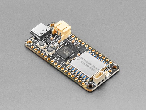
This is the Adafruit Feather RP2040 RF95 LoRa Radio. We call these RadioFruits, our take on a microcontroller with a "Long Range (LoRa)" packet radio ...
The rp2040 is a big step up from the M0 especially if you want to use CIrcuitPython
orchid narwhal
Okay Cool! I'm a little familiar with the RP2040 anyway from programming on the Pico. I'd imagine I could probably use the Pico C++ SDK with this board as well?
I'll check it out
normal drift
Good luck!
I’ve only used them with CIrcuitPython and Arduino. The pinouts are different from the pico. Not sure if that impacts using the SDK…
But it is the same RP2040 chip
orchid narwhal
Thanks for all the info!
 cosmic zephyr
Would it be possible to use a raspberry pi's antenna to measure the physical proximity of a device connected to WiFi
umbral oxide
Difficult with just one, RSSI can vary for a variety of reasons and so isn't strictly proportional to distance. In a general sense, RSSI should correlate to proximity. More than one detector can give a triangulation assist to the proximity guesstimate.
cosmic zephyr
I was thinking of getting a fleet of 4 or 5 raspberry pi zeros or esp32s or something
Although Bluetooth LE beacons look promising too
umbral oxide
there are some "art" projects and technical papers that do triangulation of signals (or detection of humans), some web searching should surface some of that
leaden sparrow
Do you want just proximity or also direction? What’s the end goal?
 velvet drift
anyone have a up-to-date guide for using LoraWAN and The Things Network? The one on the Adafruit website is deprecated (https://learn.adafruit.com/the-things-network-for-feather)
but I haven't found anything so far that is up to date with The Things stack v3.
This is my first time using Lora, using Feather M0 RFM9x LoRa controller stacked on a Ultimate GPS Featherwing. Trying to send long and lat data over to a Node.js server as frequently as possible (in open air)

Adafruit Learning System
Get connected to The Things Network by building a small weather node using a Feather M0 LoRa
normal drift
velvet drift
anyone have a up-to-date guide for using LoraWAN and The Things Network? The one...
I have been using this https://github.com/mcci-catena/arduino-lmic
 rose mountain
Hello,
Is it possible to easily establish communication between a TTGO LoRa32 and a Raspberry Pi 3B using an Adafruit HAT? I attempted this with a Waveshare SX1262, but it was unsuccessful. I'm looking for a solution that's easy to connect, like a HAT, and comes with documentation. I noticed an Adafruit LoRa HAT, but I'm uncertain if it can be used to communicate with the TTGO LoRa32. Do you have any suggestions for me?
normal drift
rose mountain
Hello,
Is it possible to easily establish communication between a TTGO LoRa32 an...
It looks like both the TTGO Lora32 and the AdaFruit boards use SX1276 modules so “in principle” they should be able communicate. I may depend on the software you are using on each. What are you planning to use?
rose mountain
normal drift
It looks like both the TTGO Lora32 and the AdaFruit boards use SX1276 modules s...
I would like to make multiple ttgo loga32 communicate with one central raspberry pi. Each ttgo is like a access controller for door. The pi performs the http request to the server to check the validity of the code entered code on the ttgo for example
The thing is adafruit lora hat isn’t easy to setup no ? I don’t find clearly a hat that I can just « plug » on the pi
normal drift
https://www.adafruit.com/product/4074 plugs into a pi
The latest Raspberry Pi computers come with WiFi and Bluetooth, and now you can add even more radio options with the Adafruit Radio Bonnets! Upgrade your Raspberry Pi with a LoRa / LoRaWAN ...
The big issue is finding compatible software.
rose mountain
normal drift
The big issue is finding compatible software.
What do you mean by software ?
rose mountain
normal drift
https://www.adafruit.com/product/4074 plugs into a pi
Yes but could you confirm that I can use the band 868Mhz ?
Because in the title it’s 915. In the description it’s said 868 and 915
normal drift
It’s also supports 868
You need software to configure the radio and to transmit and receive packets. Both units have to be configured the same and the packet format has to be something both can process.
This is the 900 MHz LoRa radio version, which can be used for either 868MHz or 915MHz transmission/reception - the exact radio frequency is determined when you load the software since it can be tuned around dynamically
That was from the linked page
https://learn.adafruit.com/adafruit-radio-bonnets. This is a guide to using the bonnet on a pi. I don’t know how you are planning to use the TTGO.
rose mountain
So from the TTGO I send a simple string, on the 868Mhz band
And from the rpi I’ll use python to catch the lora message and process an http request with it
rose mountain
normal drift
https://learn.adafruit.com/adafruit-radio-bonnets. This is a guide to using the ...
In this guide they talk about RFM9X and RFM69, is it compatible with the TTGO ? I don’t really understand what do this mean. On the TTGO I just configure the frequency band and that’s it.
normal drift
There are 2 different boards. Rfm9x and Rfm69. Only the rfm9x supports LORA.
Were you configuring the TTGO via Arduino? ?
Can you post a link to the TTGO board so I can better understand how it works?
You will need to know how the TTGO is configured and what the packet contains in order to receive and decode them on the Pi
I have to go offline for the evening. Please post a link and I’ll be happy to look at it tomorrow and try to help or hopefully someone else will jump in sooner.
rose mountain
normal drift
Were you configuring the TTGO via Arduino? ?
Yes Arduino IDE
rose mountain
normal drift
Can you post a link to the TTGO board so I can better understand how it works?

DollaTek Module sans Fil WiFi avec Carte SD LoRa32 V2.1 868Mhz ESP32 Lora avec SMA IP5306 0.96 Pouce OLED
rose mountain
normal drift
There are 2 different boards. Rfm9x and Rfm69. Only the rfm9x supports LORA.
Yes I think I have to buy the RFM95W
rose mountain
And, is it necessary to add the SMA to Ufl cable to begin ? Or with the pcb antenna I can have at least 5 m ?
normal drift
Yes, for operation at 868 MHz with LoRa. When you got your LoRa32 Board, how did you configure it? That is, did you have to upload software to it? If so, where did you get the software to load. I am trying t o understand the packet format being used to be able to tell how you may be able to receive and decode packets on your Raspberry Pi. I have also looked ad the Waveshare Sx1272 information and it is not clear to me why it should not be able to work. How did you try to use it? THe issues may all be in the software, not in the hardware. I need to know more about your project to really help.
normal drift
rose mountain
And, is it necessary to add the SMA to Ufl cable to begin ? Or with the pcb ante...
doesn’t it come with an antenna that connects to the board?
I don’t want you to buy the RFM9x board and still not have it work.
rose mountain
normal drift
Yes, for operation at 868 MHz with LoRa. When you got your LoRa32 Board, how d...
//Libraries for LoRa
#include <SPI.h>
#include <LoRa.h>

//Libraries for OLED Display
#include <Wire.h>

//define the pins used by the LoRa transceiver module
#define SCK 5
#define MISO 19
#define MOSI 27
#define SS 18
#define RST 14
#define DIO0 26


#define BAND 868E6

//packet counter
int counter = 0;

void setup() {
  //initialize Serial Monitor
  Serial.begin(115200);


  //SPI LoRa pins
  SPI.begin(SCK, MISO, MOSI, SS);
  //setup LoRa transceiver module
  LoRa.setPins(SS, RST, DIO0);

  if (!LoRa.begin(BAND)) {
    Serial.println("Starting LoRa failed!");
    while (1);
  }
  Serial.println("LoRa Initializing OK!");

  delay(2000);
}

void loop() {

  Serial.print("Sending packet: ");
  Serial.println(counter);

  //Send LoRa packet to receiver
  LoRa.beginPacket();
  LoRa.print("hello ");
  LoRa.print(counter);
  LoRa.endPacket();
  counter++;

  delay(10000);
}
Here is an example of the code that I upload to the ttgo board
rose mountain
normal drift
doesn’t it come with an antenna that connects to the board?
It is but for some reason maybe I’ll buy it on a other website to have it faster cause I’m in France
And the antenna isn’t include
normal drift
rose mountain
And the antenna isn’t include
You should not operate it with out an antenna. That is not good for the hardware and you will not receive anything.
rose mountain
Ok 👍
normal drift
rose mountain
Here is an example of the code that I upload to the ttgo board
Ah that helps.
On the Pi , you will need to create software that can receive and decode these packets. How did you try to do that with the WaveShare board? What code did you run?
normal drift
rose mountain
```cpp
//Libraries for LoRa
#include <SPI.h>
#include <LoRa.h>
//Libraries for...
Where did you get this code? Do you have a link to it?
rose mountain
normal drift
On the Pi , you will need to create software that can receive and decode these p...
I used Python, but the problem with the Waveshare is that it’s a private protocol which is not compatible with LoraWan
normal drift
Wait -- Are you using LoRaWAN or LoRa?? THat is, are you trying to communicate with the TTN LoRaWAN network or just point to poin with LoRa? These are very different projects.
rose mountain
normal drift
Where did you get this code? Do you have a link to it?
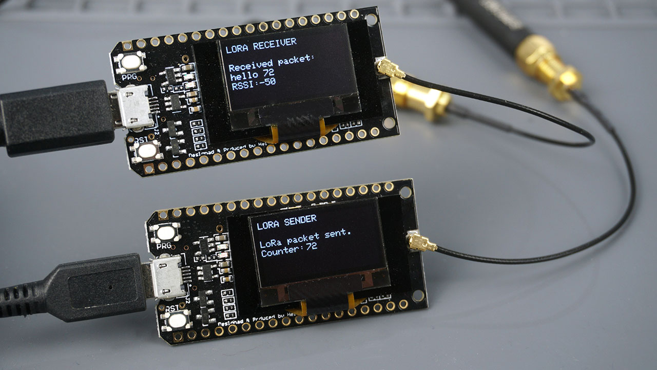
The TTGO LoRa32 SX1276 is an ESP32 development board with a built-in LoRa chip and OLED display. Learn how to send and receive LoRa packets using Arduino IDE.
rose mountain
normal drift
Wait -- Are you using LoRaWAN or LoRa?? THat is, are you trying to communicate w...
Point to point, but multiple esp32 with one pi, but yes point to point
So it’s not linked to LoraWan
normal drift
OK good.
rose mountain
Do you want the link of the Waveshare documentation ?
normal drift
yes, please.
rose mountain

From what I understood, with this hat we can only communicate with orher waveshare hat
This product uses a private protocol and does not support LoRaWAN.
normal drift
rose mountain
> This product uses a private protocol and does not support LoRaWAN.
Well, not supporting LoRaWAN is not necessary a problem since you are not using LoRaWAN but the WaveShare software may be the problem I don't know if you could operate the board with other software. That may be possible.
I see that the software you linked for the TTGO board uses https://github.com/sandeepmistry/arduino-LoRa -- that is good! That library works well on "Arduino" boards.
As far as communicating to it from a Raspberry Pi, I would expect it to be possible but it will take me some time to look for an example. I may have done this in the past, so I just need to dig through my notes. I will do that today and see if I can find anything.
For example, this library looks like it might be able to work --- https://github.com/chandrawi/LoRaRF-Python
I have not tried it myself. I'll download it and run some tests but that may take awhile.
rose mountain
normal drift
As far as communicating to it from a Raspberry Pi, I would expect it to be possi...
So you think it's possible to communicate with this Waveshare ? Because I tried lot of things and nothing changed.
rose mountain
normal drift
For example, this library looks like it might be able to work --- <https://githu...
what do you think of this ? https://github.com/chandrawi/LoRaRF-Python/blob/main/examples/SX126x/receiver.py
GitHub
Python library for basic transmitting and receiving data using LoRa and FSK modem - chandrawi/LoRaRF-Python
normal drift
That library has examples for both the SX126X and SX127X so It may well work with the waveshare board.
rose mountain
Do I have to use SX126X or SX127X ? As I understood in my case it's SX126X right ?
normal drift
It shows the connections taht are expecetd https://github.com/chandrawi/LoRaRF-Python/tree/main#hardware-configuration If the WavShre board makes these available, then it may be worth trying it.
126X for the Waveshare.
127x for the Adafruit board
rose mountain
Ok 👍
normal drift
Try it with the Waveshare board! Good Luck!
rose mountain
I'm checking the hardware configuration of the Waveshare so I've done the schema which is on the previous documentation but I don't know where to find the connection
normal drift
rose mountain
I'm checking the hardware configuration of the Waveshare so I've done the schema...
I am not seeing any schematics or pinout lists in the documentation.
rose mountain
Well, I'm stuck on this error:
Begin LoRa radio
Traceback (most recent call last):
  File "/home/../Documents/LoRaRF-Python/receiver.py", line 15, in <module>
    if not LoRa.begin() :
  File "/home/../Documents/LoRaRF-Python/LoRaRF/SX126x.py", line 293, in begin
    self.reset()
  File "/home/../Documents/LoRaRF-Python/LoRaRF/SX126x.py", line 310, in reset
    self._reset.output(LoRaGpio.LOW)
  File "/home/../Documents/LoRaRF-Python/LoRaRF/base.py", line 36, in output
    chip = gpiod.Chip(self.chip)
  File "/home/../.local/lib/python3.9/site-packages/gpiod/chip.py", line 58, in __init__
    self._chip = _ext.Chip(path)
FileNotFoundError: [Errno 2] No such file or directory
hmmm -- It looks like someone else ran into this! https://github.com/chandrawi/LoRaRF-Python/issues/20
Also looking ore at the Waveshare documentation, it looks like the Raspberry Pi Communicates to the Waveshare board via the UART so this is very different from the Adafruit board. I don't know how to make it work.
rose mountain
here is the "demo 1" that they provide
but it's weird, they use "address" in the node configuration
normal drift
#    users can transfer or receive the data directly by UART and dont
# need to set parameters like coderate,spread factor,etc.```what does that mean ?
normal drift
They may well have implemented an addressing scheme in their software.
rose mountain
because if I use the script, and send a message like 0,868,Hello World, nothing is detected by my TTGO
void loop() {
  int packetSize = LoRa.parsePacket();
  if (packetSize) {
    Serial.println("Received packet!");

    // Lecture des données du paquet
    while (LoRa.available()) {
      Serial.println(LoRa.read());
    }

    Serial.println();
  }
}
What are you expecting it to receive? What are you transmitting?
are you transmitting via the Waveshare? How is it configured? Does the TTGO have an antenna?
The frequency, code rate, spreading factor all have to match.
rose mountain
normal drift
are you transmitting via the Waveshare? How is it configured? Does the TTGO have...
yes from the Waveshare
rose mountain
normal drift
are you transmitting via the Waveshare? How is it configured? Does the TTGO have...
it's configured with the code provided bellow, when I press "i"
Yes the TTGO have antenna
node = sx126x.sx126x(serial_num = "/dev/ttyS0",freq=868,addr=0,power=22,rssi=True,air_speed=2400,relay=False)
but on the TTGO no address is configured.
So it have to print all the packet
normal drift
In the sx126x.py file from Waveshare, there is a lot of configuration of the module described. The TTGO just may not be configured to be able to receive the packets sent by the Waveshare.
normal drift
rose mountain
So it have to print all the packet
That would be a good start!
rose mountain
normal drift
In the sx126x.py file from Waveshare, there is a lot of configuration of the mod...
The frequency is configured, but for the code rate and the spreading factor where can I find them ? It's not in the provided code
normal drift
Good question!
I wonder if there is a WaveShare forum where you can get help from people more familiar with the WAveShare board?
rose mountain
There is a forum but not a discord.. I think I’ll buy the adafruit 😂
If you think it will be easier
normal drift
I will spend some time looking at the lorarf library and others to see I I can find anything that looks like it will work. with the RFM9x board. I can test that. I think it should be possible. But remember, I don't work for Adafruit and I can't make any promises 😉
rose mountain
Yes of course, thank you for your help, it’s very helpful!
I though LoRa was simplier, like we just have to communicate on the same frequency.. but looks like nop 🙂
normal drift
rose mountain
If you think it will be easier
I have done a lot of work getting the CircuitPython Library on the Raspberry Pi to work with the Arduino Radiohead library. I have also used the sandeep-mistry library used by the TTGO but have not tried using the Pi to talk to the sandeep-mistry library. I'll see if I can do that. If so, it should help you.
normal drift
rose mountain
I though LoRa was simplier, like we just have to communicate on the same frequen...
simpler... but not necessarily easy
rose mountain
Thanks, so do you think it’s a good idea to buy the Adafruit ?
Btw, have you ever heard of ESPNOW ? If so, do you think it’s similar for middle range (500m)
normal drift
I always think it's a good idea to buy from Adafruit 😉 I like to support them! I think it has a good chance of working. I was also thinking that you could use something like an ESP32S2 or S3 with the Adadfrut RFM9x boards they have - I am thinking of the esp32s2 feather with the rfm9x featherwing. Then you can use the same arduino Library as on the TTGO. The esp32s2 also has WiFi so it can relay packets to the internet.
normal drift
rose mountain
Btw, have you ever heard of ESPNOW ? If so, do you think it’s similar for middl...
I have only tried a few very simple ESPNOW examples. I don't know much about it.
I have no idea if it can go 500m
ESP-NOW has a limited signal range, typically around 220 meters under ideal conditions. from a quick search
rose mountain
Yes I found also 220m but some persons talk about 480m, so that’s why
rose mountain
normal drift
I always think it's a good idea to buy from Adafruit 😉 I like to support them! ...
Why Esp32s2? It contains a lora module ?
normal drift
rose mountain
Why Esp32s2? It contains a lora module ?
No - it is a WiFi module -- you add the rfm9x board to it.
rose mountain
Ok
normal drift

The ESP32-S3 has arrived in Feather format - and what a great way to get started with this powerful new chip from Espressif! With dual 240 MHz cores, WiFi and BLE support, and native USB, ...
this is an esp32s3 -- as an example
https://www.adafruit.com/product/3231 can be attached

Add short-hop wireless to your Feather with these RadioFruit Featherwings. These add-ons for any Feather board will let you integrate packetized radio (with the RFM69 radio) or LoRa radio ...
It is just suggestion of another approach -- There are many options!
rose mountain
I see. Looks like difficult to make LoRa working. I'll investigate and maybe try in a first time to use Adafruit radio bonnet and the TTGO
I'm mostly a programmer and not really familiar with electronic to be honest, that's why a hat and a TTGO which as nothing to solder is easier for me
normal drift
rose mountain
I see. Looks like difficult to make LoRa working. I'll investigate and maybe try...
If nothing else, it will be a good learning experience! Yes, the bonnet and Pi are easy to get started with. I have mostly used them to communicate with other Adafruit RFM9x boards. That combination works well. I do think it will be possible to get it to work with the TTGO... it may not be easy 😉
But "it is only software" as I have been told many tines....
rose mountain
Ok ok, I see
Thank you for your help
I’ll buy the adafruit radio bonnet and try with the documentation
normal drift
You are welcome . Good luck! There are many other people on this discord who may be able to help as well. Keep asking questions!
normal drift
rose mountain
Well, I'm stuck on this error:
```
Begin LoRa radio
Traceback (most recent call ...
FYI -- as a quick workaround to this, I am able to get the LoRaRF example to run (and detect my RRF9x board) by just copying the LoRaRF library into my working directory instead of installing it via pip. Something appears to be wrong with the pip installation. So, at least it connects to the board. Now I'll see if I can transmit or receive anything....I need to set up another board for that.
rose mountain
normal drift
FYI -- as a quick workaround to this, I am able to get the LoRaRF example to run...
did you use the approach described here? https://github.com/chandrawi/LoRaRF-Python/issues/20
Because I didn't use pip3 install LoRaRF
GitHub
Hi! I try to get the library running on an RPi 3b+ with the 64bit OS headless. The board I am using is the waveshare board with SX1262 via SPI and GPS via serial. When I compare the version if inst...
I use the same approach as bellow but not in a virtual environment
normal drift
I set up a virtual environment with
python -m venv lora --system-site-packages
but did not installt LoRaRF via pip
I just copied the entire LoRaRF folder from the repostory to my working directory
It also works without the virtual environment
rose mountain
I’ll try again
still the same issue, I've done:
python -m venv lora --system-site-packages
source lora/bin/activate
git clone https://github.com/chandrawi/LoRaRF-Python.git
cd LoRaRF-Python

pip3 install wheel
pip3 install spidev
pip3 install gpiod

cp examples/SX126x/receiver.py .
python3 receiver.py
what do you mean by "working directory" ? In my example, am I in the good directory ?
normal drift
you should not need to install wheel,spidev or gpiod -- Try copying the source folder to this directory cp -r ../../LoRaRF .
However -- I do not expect it to ever work with the Waveshare board since it does not use SPI....
but the python code shoud run
rose mountain
normal drift
you should not need to install wheel,spidev or gpiod -- Try copying the source ...
So you are copying the LoraRF folder in the example folder and run receiver.py?
normal drift
yes
normal drift
I am making some progress. I can now transmit packets from a Raspberry Pi Pico(Rp2040) board with an RFM9x module using the Sandeep Mistry Arduino-Lora library to my Raspberry Pi 400 with an RFM9x bonnet attached using the LoRaRF library. Since this is the same arduino library that the TTGO board uses, I think it is very encouraging.
normal drift
@rose mountain Did you get the LoRaRF code to execute?
The test I ran gives me confidence that you should be able to communicate between your TTGO board and your Raspberry Pi with the RFM9x Bonnet. What version of Pi and what version of RaspiOS are you running? My test was with a Raspberry Pi 5 and Bookworm.
rose mountain
I had to disconnect for some hours, I just got home
rose mountain
normal drift
The test I ran gives me confidence that you should be able to communicate betwee...
You mean the adafruit radio bonnet ? Nice
rose mountain
normal drift
<@498432113666818058> Did you get the LoRaRF code to execute?
I’ll try in few minutes
rose mountain
Should I continue to try with the Waveshare ?
normal drift
I fund the issue with installing LoRaRF via pip -- it is describd here https://github.com/chandrawi/LoRaRF-Python/issues/19. I got it to work by cloning the git repository then installing the latest version via pip install . while in the top level of the repository. It now runs ok in my virtual environment.
normal drift
rose mountain
Should I continue to try with the Waveshare ?
No, I would not bother... wait for the RFM9x board.
rose mountain
Ok 👍
(could you please just check the link given in DM please, it's not adafruit website)
normal drift
It is nice to see that the LoRaRF library is still being actively maintained. I'm glad you got me to try it!
rose mountain
normal drift
It is nice to see that the LoRaRF library is still being actively maintained. I...
😂 that's nice
I'll try with the waveshare to be sure
normal drift
The WaveShare board uses this module https://www.cdebyte.com/products/E22-900T22S and only supports the UART communication and it must have some sort of controller on board to communicate with the SC1272. The RFM9x boards use SPI to communicate with the SX1276 and the SPI pins are available to connect to the Raspberyy Pi or other Microcontroller.
rose mountain
So no need to try again with the Waveshare right ?
normal drift
It might be possible to write software to make the Waveshare board compatible with the RFM9x boards, but the LoRaRF library needs the SPI interface so it will not work.
normal drift
rose mountain
So no need to try again with the Waveshare right ?
That is my opinion.
rose mountain
Ok thanks, I'll order the adafruit radio bonnet definitely 😂
But I'm still not able to run the python script.
normal drift
hmm did you try re-installing it from the source files? First uninstall it then from the LoRaRF-Python folder run pip install .
rose mountain
how do you uninstall it ?
I installed it with pip install . as you said
rose mountain
same error..
could you show what command line are you doing from the cloning of the repo to the start of the script ?
I remove everything
normal drift
What version of RaspiOS are you using?
rose mountain
bullseye
normal drift
I am using bookkworm that mya be an issue -- I'll try a clean install and psot the commands.
rose mountain
Will be weird if it's the reason..
normal drift
  317  cd test
  318  git clone https://github.com/chandrawi/LoRaRF-Python.git
  319  python -m venv lora --system-site-packages
  320  source lora/bin/activate
  321  cd LoRaRF-Python
  322  pip install .
  323  cd examples/SX127x/
  324  python receiver.py
I get ```(lora) pi@gjnpi400usb2:~/projects/test/LoRaRF-Python/examples/SX127x $ python receiver.py
Begin LoRa radio
Traceback (most recent call last):
File "/home/pi/projects/test/LoRaRF-Python/examples/SX127x/receiver.py", line 15, in <module>
raise Exception("Something wrong, can't begin LoRa radio")
Exception: Something wrong, can't begin LoRa radio
with a few modifications I get ```Begin LoRa radio
Set frequency to 915 Mhz
Set RX gain to power saving gain
Set modulation parameters:
Spreading factor = 7
Bandwidth = 125 kHz
Coding rate = 4/5
Set packet parameters:
Explicit header type
Preamble length = 12
Payload Length = 15
CRC on
Set syncronize word to 0x34
-- LoRa Receiver --
hello 12 51
Packet status: RSSI = -43.00 dBm | SNR = 6.50 dB
hello 12 52
Packet status: RSSI = -43.00 dBm | SNR = 6.25 dB
the only changes neede were in the configuration section ```# Begin LoRa radio with connected SPI bus and IO pins (cs and reset) on GPIO
SPI is defined by bus ID and cs ID and IO pins defined by chip and offset number
spi = LoRaSpi(0, 1)
cs = LoRaGpio(0, 7)
reset = LoRaGpio(0, 25)
LoRa = SX127x(spi, cs, reset)
Also on the Arduino transmitter I has to set the "SyncWord" to 0x34 to match the setting in LoRaFM.
rose mountain
normal drift
```316 mkdir test
317 cd test
318 git clone https://github.com/chandrawi/...
yep still same error:
FileNotFoundError: [Errno 2] No such file or directory
Hope it will work with the adafruit.
normal drift
I'm not sure what problem is?
rose mountain
same as before
Traceback (most recent call last):
  File "/home/../test/LoRaRF-Python/examples/SX126x/receiver.py", line 17, in <module>
    if not LoRa.begin() :
  File "/home/../test/lora/lib/python3.9/site-packages/LoRaRF/SX126x.py", line 293, in begin
    self.reset()
  File "/home/../test/lora/lib/python3.9/site-packages/LoRaRF/SX126x.py", line 310, in reset
    self._reset.output(LoRaGpio.LOW)
  File "/home/../test/lora/lib/python3.9/site-packages/LoRaRF/base.py", line 36, in output
    chip = gpiod.Chip(self.chip)
  File "/home/../.local/lib/python3.9/site-packages/gpiod/chip.py", line 58, in __init__
    self._chip = _ext.Chip(path)
FileNotFoundError: [Errno 2] No such file or directory
GitHub
Hi! I try to get the library running on an RPi 3b+ with the 64bit OS headless. The board I am using is the waveshare board with SX1262 via SPI and GPS via serial. When I compare the version if inst...
Ok it's not important now. With the adafruit radio bonnet I'll use the adafruit-circuitpython-... librairies right ?
normal drift
If it's possible, you could try it with bookworm.
normal drift
rose mountain
Ok it's not important now. With the adafruit radio bonnet I'll use the `adafruit...
For this library, you don't use any of the CircuitPython libraries.
rose mountain
wait, what ?
Adafruit Learning System
Upgrade your Raspberry Pi with a LoRa or Packet radio, so it can communicate over very long distances!
normal drift
I use the CircuitPython rfm9x library a lot, but it is only compatible with boards that use the RadioHead packet header. The sandeepmistry/adruino-lora does not use it.
rose mountain
If I follow the link bellow, it's correct no ?
normal drift
You "can" use CircuitPython libraries with it, but you don't have to.
The Adafruit guide assumes you are using the CircuitPython libraries.
rose mountain
Ok, so you're saying that it should work with the LoRaRF-python library
rose mountain
Ok.. lets talk about it when I get the adafruit radio bonnet and bookworm installed !
normal drift
Yes! Good luck. I have to go offline now. I hope it all works!
rose mountain
Thank you again ! Bye
normal drift
FYI -- I did confirm that I was not able to install the LoraRF library correctly under bullseye but it does work with bookworm. In this case I created a new system on a raspberry pi zero and install bookworm lite (32 bit). I enable the SPI and I2C interfaces. I then followed the install process mkdir test cd test git clone https://github.com/chandrawi/LoRaRF-Python.git python -m venv lora --system-site-packages source lora/bin/activate cd LoRaRF-Python pip install . cd examples/SX127x/ python receiver.py Of couse this example will fail to initialize the radio, but the python script does run... as above. My modified example also works normally.
rose mountain
@normal drift maybe the problem comes from here, I use an rpi 3b+
normal drift
rose mountain
<@343570430042308609> maybe the problem comes from here, I use an rpi 3b+
It works ok for me on a Pi zero and a Pi4 so I would expect it to be fine on a 3B+. I just think there is some issue with the gpiod library that is ok with Bookworm, but not Bullseye. Hopefully the library maintainer will fix it soon and respond to the issues.
rose mountain
Ok nice, I'll setup all of this today, thanks
rose mountain
normal drift
FYI -- I did confirm that I was not able to install the LoraRF library correctly...
It's working fine !
I have this error:
    raise Exception("Something wrong, can't begin LoRa radio")
Exception: Something wrong, can't begin LoRa radio
``` but that's itYay! Good news!
rose mountain
I still use the Waveshare, I'm waiting for the adafruit but I think it's due to wrong gpio number right ?
normal drift
The LoRaRF code cannot communicate at all with the Waveshare board that you have. No point in trying.
rose mountain
Ok so perfect 😂
normal drift
When you have the Adafruint bonnet, you will have to change the code example like this <#help-with-radio message>
to set the pins correctly
normal drift
Glad to help .. I hope it all works for you!
I also did some testing and found that I can actually send/receive packets between a system using LoRaRF and one using the CircuitPython adafruit_rfm9x. It is a bit tricky since the have different header formats, but the packets do arrive! This has been a very useful exercise for me. I will spend more time looking into how the LoRaRF library actually works to see if it can work cleanly with the CircuitPython library. This makes me think it also may be possible to receive/transmit packets between the Circuitpython library and the samdeepmistry arduino-lora library. That would be very useful. I'll keep you updated on my progress. If it works, then you may also have the option of using the Adafruit CircuitPython library on your Raspberry Pi to communicate with the TTGO.
rose mountain
Oh ok ! So what do you suggest for me which is a beginner with LoRa ? Use Circuitpython library ?
normal drift
No. I suggest using the LoRaRF library to start.
You should follow the guide and use the Circutpython library to test out the bonnet when you first get it to make sure it works properly. But for your first attempt at communicating with the TTGO board, I think the LoRaRF library will be better.
rose mountain
Okay, I will see tomorrow when it arrives. Thanks
normal drift
There are a few steps to using the CircuitPython Libraries on a Pi -- you have to install "Blinka" on the Pi https://learn.adafruit.com/circuitpython-on-raspberrypi-linux and there are some special steps for Bookworm....
normal drift
@rose mountain I may want to correct my opinion. It looks like the CircuitPython library "can" actually receive OK from the arduino-lora library with a few simple changes to the statndard code. You just have to make sure the header is not "stripped off" Here is an example using the circuitpython library that receives from the arduino-lora library
# Author: Jerry Needell
#
import board
import busio
import digitalio
import adafruit_rfm9x

# Define radio parameters.
RADIO_FREQ_MHZ = 915.0  # Frequency of the radio in Mhz. Must match your
# module! Can be a value like 915.0, 433.0, etc.

# Define pins connected to the chip.
CS = digitalio.DigitalInOut(board.CE1)
RESET = digitalio.DigitalInOut(board.D25)

# Initialize SPI bus.
spi = busio.SPI(board.SCK, MOSI=board.MOSI, MISO=board.MISO)

# Initialze RFM radio
rfm9x = adafruit_rfm9x.RFM9x(spi, CS, RESET, RADIO_FREQ_MHZ)

# Wait to receive packets.
print("Waiting for packets...")
# initialize flag and timer
while True:
    # Look for a new packet:
    packet = rfm9x.receive(with_header=True)
    # If no packet was received during the timeout then None is returned.
    if packet is not None:
        # Received a packet!
        # Print out the raw bytes of the packet:
        print("Received (raw header+payload):", [hex(x) for x in packet[0:]])
        print("Received (raw header+payload): {0}".format(packet[0:]))
        print("RSSI: {0}".format(rfm9x.last_rssi))
        # send reading after any packet received
Ok so tomorrow I'll use this code
normal drift
Waiting for packets...
Received (raw header+payload): ['0x68', '0x65', '0x6c', '0x6c', '0x6f', '0x20', '0x37', '0x39']
Received (raw header+payload): bytearray(b'hello 79')
RSSI: -59
Received (raw header+payload): ['0x68', '0x65', '0x6c', '0x6c', '0x6f', '0x20', '0x38', '0x30']
Received (raw header+payload): bytearray(b'hello 80')
RSSI: -60
Received (raw header+payload): ['0x68', '0x65', '0x6c', '0x6c', '0x6f', '0x20', '0x38', '0x31']
Received (raw header+payload): bytearray(b'hello 81')
RSSI: -59
Please give it a try. It will also work with Bullseye!
rose mountain
Now Bookworm is installed but yes I'll try !
With a simple antenna on the rpi and on the ttgo, how much range will I have ? 1 km ?
normal drift
1Km should be OK -- depends on what is in the way -- walls, trees, hills -- but with direct line of site 1Km, should be possible.
I usually just use a piece of wire on the Pi.
rose mountain
Actually the goal is to use LoRa to replace the current communication system of my access controllers. There is multiple doors, light or whatever, which have to ask permission, depends on the code provided by the customer, to the rpi. So for example the ttgo will read a 6 digitcode and send it to the rpi, and the rpi will send a response just with the action to execute. Do you think LoRa is correct for this type of use ?
(rpi has to make a http request to my external server before responding)
normal drift
hmmm -- if you are going through multiple doors and walls, you may have problems with 1Km range. Or are the antennae able to be outside?
One issue you may run into is that there will be missed packets. You will have to allow for that.
rose mountain
no I was saying that each access controller could be a door for example, but in theory there won't be multiple door blocking the signal, maybe 1 or 2 maximum
rose mountain
normal drift
One issue you may run into is that there will be missed packets. You will have t...
mmmh interesting
normal drift
If the buildings are 1KM apart, I am not sure it will work well. You will need to do some testing...
rose mountain
I can buy more powerfull antenna without problem if it's the solution
normal drift
rose mountain
mmmh interesting
missed packets are going to happen. There may be collisions if two units try to send at the same time and just due to noise. The RadioHad and Circuitythin libraries implement what is called "reliable datagram" mode which includes transmission of an Ack packet (acknowledgment) after every packet. If it is not received, the sender retransmits...
rose mountain
normal drift
missed packets are going to happen. There may be collisions if two units try to ...
Ok so it's possible to detect if the packet hasn't been delivered and send it again
like EspNow
normal drift
Yes. but this is not implmented in the adruino-lora library so the TTGO will not use it.
If you are able to update the TTGO software, you may be able to do something similar.
But even with it implmented, there are still failed packets. You just have to be able to deal with that. It will not be 100% reliable.
rose mountain
Yes I can update the TTGO software it's mine
normal drift
So you can implement some sort of "handshake", maybe.
rose mountain
Now that you have an idea of the project, do you think LoRa is better or EspNow for this purpose ?
Actually it's a big deal, LoRa is usefull in my case for long range, and no needs to save all MacAddress.
normal drift
My understanding is that EspNow has much shorter range
rose mountain
Yes that's right
I'll see how it's going with lora tomorrow when I get the radio bonnet
normal drift
Good luck! If nothing else it will be a good learning experience 😉
rose mountain
yes absolutely !
normal drift
I assume there is a reason that you don't want each device to connect to the Internet for this communication.
rose mountain
This is the actual system, but I'm not satisfied. Some customers have really bad connection so even with 1,5 meter WiFi antenna on the router the connection isn't stable and some other reasons yes. Would like to see if the performance and the stability can be increase by using LoRa or EspNow
Moreover, using a central rpi is usefull for remote maintability
normal drift
ah..sounds like a great project. It will be interesting to see how it all works.
rose mountain
If you're interest into it, we can talk about it in DM of course !
normal drift
Now, I have to go take my dog for a walk! She has been very patient.... Good luck with setting up the bonnet tomorrow.
normal drift
@rose mountain Does your application require that the Pi be able to transmit to the TTGO? If so, then there will be some problems using the CircuitPython library. It expects there to be a 4 byte "header" on every packet that can be used for addressing. For receiving, in the example I gave you, it is easy to just treat the header bytes as just part of the data, but on on transmit, the library will insert the 4 header bytes into any packet sent. You will have to modify the TTGO software to accommodate this. The LoRaRF library does not assume any header is present so it may be the better option.
normal drift
It would also not be difficult to take the adafruit_rfm9x library and strip out the header (and other things you don't need). I may do this myself just to test it. Let me know if you are interested in it if I do.
primal warren
One of the big advantages to open source
rose mountain
normal drift
<@498432113666818058> Does your application require that the Pi be able to trans...
I just received the adafruit radio bonnet. Yes the pi must be able to send message to the ttgo, like reply
normal drift
OK -- I have to go offline for a few hours. I will work on a simplified circuitpython library this afternoon. Good luck with your initial testing!
rose mountain
Hi, so it's working well with adafruit librairies. I got some issue with LoRaRF-Python but still trying
With LoRaRF-Python I'm able to send data but not to get data
rose mountain
However, I can't manage to send a message from the TTGO and receive a response from the Pi to check if the message has been sent correctly.
here is my TTGO code:
// ...
#define BAND 868E6
// ...

int counter = 0;
void setup() {
  Serial.begin(115200);

  if(!display.begin(SSD1306_SWITCHCAPVCC, SCREEN_ADDRESS)) {
    Serial.println(F("SSD1306 allocation failed"));
    for(;;);
  }

  display.display();
  delay(2000);
  display.clearDisplay();

  SPI.begin(SCK, MISO, MOSI, SS);
  LoRa.setPins(SS, RST, DIO0);

  if (!LoRa.begin(BAND)) {
    Serial.println("Starting LoRa failed!");
    while (1);
  }

  Serial.println("LoRa Initializing OK!");
  delay(2000);
}

void loop() {
  Serial.print("Sending packet: ");
  Serial.println(counter);

  LoRa.beginPacket();
  LoRa.print("hello ");
  LoRa.print(counter);
  LoRa.endPacket();

  display.clearDisplay();
  display.setTextSize(1);
  display.setTextColor(SSD1306_WHITE);
  display.setCursor(0, 0);
  display.print("Last Packet:");
  display.setCursor(0, 10);
  display.print(counter);
  display.display();

  bool acknowledgmentReceived = false;
  unsigned long startTime = millis();
  while (!acknowledgmentReceived && (millis() - startTime < 10000)) { // wait 10 seconds
    if (LoRa.parsePacket() > 0) {
      acknowledgmentReceived = true;
      Serial.println("Acknowledgment received!");
      display.setCursor(0, 20);
      display.print("Ack received!");
      display.display();
    }
  }

  if (!acknowledgmentReceived) {
    Serial.println("No acknowledgment received. Transmission failed.");
    display.setCursor(0, 20);
    display.print("Transmission failed");
    display.display();
  }

  counter++;

  delay(5000);
}
I use your code bellow with this:
print("Received (raw header+payload):", [hex(x) for x in packet[0:]])
print("Received (raw header+payload): {0}".format(packet[0:]))
print("RSSI: {0}".format(rfm9x.last_rssi))
res = rfm9x.send(bytes("resp!\r\n","utf-8"))
print("Resp send: ", res)
``` It's always `True`If I use the code given here: https://learn.adafruit.com/adafruit-radio-bonnets/sending-data-using-a-lora-radio
I received all packets
normal drift
When you send a packet from CircuitPyhton, it will have the 4 byte header added to the beginnning. Will that cause problems on the TTGO? It won't seed the "resp!" in the first 5 bytes - they will be starting at the 5th byte of the received packet. This may not be the problem since it looks like you are just looing for any packet.
on the LoRaRF transmitter test, did you comment out the setting the SyncWord LoRa.setSyncWord(0x34) ors set it to the default value of 0x12. The TTGO is probably leaving the default setting at 0x12
normal drift
rose mountain
If I use the code given here: https://learn.adafruit.com/adafruit-radio-bonnets/...
I'm confused... does the TTGO receive these packets, just not the ones from the code using my example? One suggestion is to try adding a delay between the receive and send in the CircutiPython code. The TTGO is writing to the display between its send and receive, and perhaps is missing the response if it gets set to quickly....just a guess -- try adding a time.sleep(.25)
normal drift
@rose mountain if you want to give it a try, I have created a quick version of a simplfied rfm9x module -- I have named it rfm9x_lite. You are welcome to try it. The code and some examples are at https://github.com/jerryneedell/rfm9x_lite . It was a quick hack of the existing library so more work is needed, but it may be useful.
I ran this on my arduino-lora side to test it with the rfm9x_arduino_lora.py script running on the Pi ```#include <SPI.h>
#include <LoRa.h>
const int csPin = 6; // LoRa radio chip select
const int resetPin = 9; // LoRa radio reset
const int irqPin = 5; // change for your board; must be a hardware interrupt pin
int counter = 0;
void setup() {
Serial.begin(9600);
//while (!Serial);
Serial.println("LoRa Sender");
// override the default CS, reset, and IRQ pins (optional)
LoRa.setPins(csPin, resetPin, irqPin); // set CS, reset, IRQ pin
if (!LoRa.begin(915E6)) {
Serial.println("Starting LoRa failed!");
while (1);
}
LoRa.setTxPower(12);
LoRa.setSignalBandwidth(125000);
LoRa.setSpreadingFactor(7);
//LoRa.setSyncWord(0x34);
LoRa.enableCrc();
}
void loop() {
Serial.print("Sending packet: ");
Serial.println(counter);
// send packet
LoRa.beginPacket();
LoRa.print("hello ");
LoRa.print(counter);
LoRa.endPacket();
bool acknowledgmentReceived = false;
unsigned long startTime = millis();
while (!acknowledgmentReceived && (millis() - startTime < 10000)) { // wait 10 seconds
if (LoRa.parsePacket() > 0) {
acknowledgmentReceived = true;
Serial.println("Acknowledgment received!");
}
}
if (!acknowledgmentReceived) {
Serial.println("No acknowledgment received. Transmission failed.");
}
counter++;
delay(5000);
}
Responses were received by the arduino-lora board. I do think the delay in the CircuitPython code may be necessary. I don't have the display on my system so I can't really test that. I did not need it for my test case, without the display, so I am not sure.
rose mountain
Hi, I'm back home, I'll try ! Thanks for the help
rose mountain
normal drift
I'm confused... does the TTGO receive these packets, just not the ones from the ...
It works with the delay !
With small antenna like that, what range can I have ?
normal drift
Which antenna are you using?
rose mountain

 normal drift
I would expect it to work as well or better than a plain wire! I would expect that you can go several hundred meters, maybe even a km depending on what is in the way. But I am not an expert on range. I have only done a small amount of testing by walking around my neighborhood with one radio inside and lots of trees, houses and hills. hundreds of meters is easy. Kilometers is not.
rose mountain
Do you know of any antennas with an effective range of around a kilometer (or more) ?
Anyway, thank you, indeed, it's much better when it works!
normal drift
Hopefully someone with more antenna experience will comment. Do you have a link to the antenna you are using?
rose mountain
I don't have any link, the one on the pi is the one from the waveshare and the other one came with the ttgo. But anyway I want to purchase better ones
normal drift
There is this one from SparkFun https://www.sparkfun.com/products/15597
oops -- 902-928 -- outside your range
There are so many variables for the range. I think it best to just try it with what you have.
rose mountain
By the way, I noticed that Adafruit is selling some microcontrollers directly with integrated LoRa. Could the previous code be uploaded to one of them? Do you know if any of them has more processing power than an ESP32 CPU, even if it's more expensive? Do you think it could be a good idea to replace my ESP32 with an Adafruit microcontroller?
normal drift
The two they have are the Feather M0 RFM9x and Feather Rp2040 RFM9X. I would not recommend the M0 board for CircuitPython. It works well with Arduino. It has very little RAM and is not well suited to running CircuitPython. The Feather RP2040 RFM9x version is much better but it does not have Wifi like the ESP32S2. It also has an issue that if the antenna is too close to the board, it can cause problems. It is not a problem if you use an antenna like the one you have as long as you keep it a few cm's from the board. In terms of processing power, I think the ESP32 will outperform both of them.
You also can try raising the TxPower. The default is at 17 on the aduino-lora library -- and it can go up to 23. The default is 13 in the CircuitPython library.
rose mountain
What's the influence of the TxPower ? The power of the signal ?
normal drift
Yes -- it increases the output power and should increase the range.
rose mountain
Ok so I can set up both of them to 23 without problem no ?
normal drift
rose mountain
Ok so I can set up both of them to 23 without problem no ?
You should be able to.
rose mountain
Again.. other question
To secure my communication I would like to use private/public key and timestamp to check if the message is not a copy from a old one, what do you think ?
Moreover, in the actual system, the ttgo send the request to the rpi, the rpi send a « temporary » response to say « yes the message has been received » , process the request, and send an action to execute to the ttgo, for example: open the door. In my logic, if the ttgo doesn’t have the « temporary » response, I send the message again. But if the reply of the « temporary » response failed, should I sens it again ? I think yes but I’m not sure if the whole idea is correct or not
normal drift
rose mountain
To secure my communication I would like to use private/public key and timestamp ...
I know nothing about public/private keys but you can use a simple sequence counter to check for repeated requests. Your approach sounds fine, but complicated.
normal drift
rose mountain
Moreover, in the actual system, the ttgo send the request to the rpi, the rpi se...
In the “reliable datagram “ mode, the sender retransmits up to a set limit of times if the ACK is not received. Checking for duplicate messages makes it ok even if it is the ACK that was missed
Are you planning to implement an addressing scheme as well so you know which device is asking for an action?
primal warren
rose mountain
Moreover, in the actual system, the ttgo send the request to the rpi, the rpi se...
The RadioHead library supports addressing, encryption, reliable transport, and so forth
normal drift
primal warren
The RadioHead library supports addressing, encryption, reliable transport, and s...
Yes, the RadioHead library is the preferred option for working with the CircuitPython library on the Pi. I don't know if there is any reason why it cant be used with the TTGO board. http://www.airspayce.com/mikem/arduino/RadioHead/
I was under the impression that the TTGO board was constrained to use the arduino-lora based library. If switching to the Radiohead library is an option, it should be considered.
rose mountain
normal drift
Are you planning to implement an addressing scheme as well so you know which dev...
yes
I was thinking that I can send in the message the access controller to target and if the id correspond, then the message is at the good destination. But it implies that I can't flash all my access controller with the same code (I have to change the ID) but that's it.
Am I able to use RadioHead on my rpi with python ? I only saw C implem. So I have to change the board. What do you suggest ? An external module on a esp32 ? Am I really required to use RadioHead ?
It doesn't look easy to use.
normal drift
rose mountain
Am I able to use RadioHead on my rpi with python ? I only saw C implem. So I hav...
Radiohead would be only for the TTGO board, not the Pi. It is compiled via the Arduino IDE like the arduino-lora library. It should work with the TTGO board. It is just an option. You are not required to use it. The benefit is that it already has support for addressing and acknowledging of packets. If you stay with the arduino-lora library, you will have to recreate some of these features. That is your choice.
rose mountain
normal drift
Yes, the RadioHead library is the preferred option for working with the Circuit...
You've said that I can't use it with the TTGO no ?
normal drift
i did not. i think you can use it with the TTGO. I thought you only wanted to use the arduino-lora library for some reason.
rose mountain
Oh ok right. I'll try with the RadioHead library
normal drift
good luck. I am only trying to provide you with options, not tell you how to implement your project.
rose mountain
yes thanks !
Hoveover, if I use RadioHead on the TTGO, I'll send a message using a server addresse right ? But with adafruit-circuitpython-rfm9x there is no such system to declare address
As I understood, adafruit-circuitpython-rfm9x is mostly for point to point communication. In my case, multiple client will communicate with the central rpi. Is there any problem ?
normal drift
The Adafruit CircuitPython library uses the same addressing scheme as the RadioHead library. It can handle multiple devices communication with a central device. It uses the same 4 byte header for the addressing. Take a look at the example rfm9x_node1_bonnet.py in https://github.com/adafruit/Adafruit_CircuitPython_RFM9x/tree/main/examples It shows how a Raspberry Pi with address 1 can talk to another RadioHead (or CircuitPython) device with address 2. Also look at the other rfm9x_node... examples. The examples with "_ack" use the RadioHead "reliable datagram" mode to do the automatic retransmission of packets if they are not acknowledged. In your case, you can assign an address to the Raspberry Pi then each of the TTGO devices can have its own address. I hope that makes sense.
Actually, you should start here https://learn.adafruit.com/adafruit-rfm69hcw-and-rfm96-rfm95-rfm98-lora-packet-padio-breakouts/circuitpython-for-rfm9x-lora THe guides are from the "breakout boards", but the radio module and operation is the same for the bonnet.
rose mountain
What's the point of the adresses ? If a message is send with an adresse no one can detect it ? Or it's just usefull to know if this packet is for "me" or not ?
rose mountain
normal drift
Actually, you should start here <https://learn.adafruit.com/adafruit-rfm69hcw-an...
I didn't remember if talk about it or not, but should I use a adafruit breakout board with my esp32 ? or it's better to stay on a ttgo ?
normal drift
Which Esp32 board do you have? Can you run CircuitPython on it?
rose mountain
the basic one
normal drift
Do you have a link to a description?
rose mountain
you can google that: "ESP32 NodeMCU Module WLAN WiFi Dev Kit C Development Board"
But why would I want to use CircuitPython on it ?
I can use <LoRa.h> as on the TTGO
the TTGO is using a ESP32 cpu
rose mountain
rose mountain
What's the point of the adresses ? If a message is send with an adresse no one c...
I think I will continue to use the current system and implement my own Ack method, but it depends on whether there is a valid reason for using addressing !
Even if a message is sent with an address, every one can read it no ?
or the message is "protected" and nobody except the correct address can catch it
normal drift
If you run CircuitPython on it, then you can use the same adadfuit_rfm9x library on both ends. You can program both in Python. But I don't see that board in the list of CircuitPyhton boards so that may not be an option.
normal drift
rose mountain
or the message is "protected" and nobody except the correct address can catch it
All units will "see" the message. They just have to know to ignore them if they are not addressed to them.
normal drift
rose mountain
I think I will continue to use the current system and implement my own Ack metho...
That is fine. I'll be happy to help if I can.
rose mountain
Ok, thank you a lot for all the answers ! I discovered the LoRa world.
Even if it's working, I hope I won't do anything foolish, while using my encrypt method, my ack method. I would like to do the things correctly.
So, to summarize, I'll continue to use the current software on both boards. I'll employ my ACK method, my custom encryption message, and my addressing. Does that sound good to you? Like, nothing seems foolish?
it's to implement in my current project, so a important and big one (replace wifi)
normal drift
It does not sound foolish, at all. It sounds like you are very capable of writing the code you need. It does sound complicated and I think it will take a lot of experimentation to get it all working but that is part of the fun 😉 You are doing something more complicated than anything I have done. I only do projects for fun around my house. Yours is a much more serious application. I think you have the tools you need. It will take time to understand how to use them.
rose mountain
Yes that what I'm going to do, thanks again 🤝
normal drift
You are welcome!
rose mountain
Hello @normal drift ,
I would like to know more about handling LoRa in my system. I have a few questions; it's not urgent, so take your time whenever you can.
One of my biggest uncertainties is about the ack packet. I will use "T" to represent the TTGO and "R" for my Raspberry Pi. If T sends a request to R, R will first reply with an ack message, then make the HTTP request to the server and send an action to perform to T. But what happens if the ack message cannot be sent? T will think that his message was not received by R, potentially causing issues in the system. Do you have an idea of how to handle this properly?
Regarding other matters, I mentioned that T will send a message to R, then R will proceed with the HTTP request, which is asynchronous. But what happens if, at this moment, another T sends a message? Will R receive the message, or will it be skipped unintentionally?
For these two problems, there is not a huge impact for a simple door system. However, for lights, it could break everything if R responds with a message and T fails to send the ack message. In that case, R will think the action isn't sent, and it will send the action again.
While my current implementation works, I prefer to prevent bugs. In short, tell me what you think, and if you have any advice, I'm very curious! Thank you!
 short nimbus
Typically you'd use some sort of crc and a message number to know if you missed a message and if the packet is valid along with a start and end bits series (not necessarily a letter)
then you'd queue it up in like a stack FIFO style using the message #. Which would then process the message that take care of the async part
like you could use AX.25 and HDLC frames transmitted over LoRa
normal drift
rose mountain
Hello <@343570430042308609> ,
I would like to know more about handling LoRa in ...
These are good questions and I think you are going to have to do a lot of experimentation to find out what works for you and if you can achieve your goals. In my experience. the CircuitPython RFM9x library, especially on a Raspberry Pi, is not completely reliable. This is made clear in the documentation ```Remember this library makes a best effort at receiving packets with pure Python code. Trying to receive packets too quickly will result in lost data so limit yourself to simple scenarios of sending and receiving single packets at a time.
Also note this library tries to be compatible with raw RadioHead Arduino library communication. This means the library sets up the radio modulation to match RadioHead’s defaults and assumes that each packet contains a 4 byte header compatible with RadioHead’s implementation. Advanced RadioHead features like address/node specific packets or “reliable datagram” delivery are supported however due to the limitations noted, “reliable datagram” is still subject to missed packets but with it, sender is notified if a packet has potentially been missed.``` You will miss packets and you have to be able to deal with that.
I think you will need to spend some time experimenting with the various libraries available and see what works for you. I am glad to see the comments by @short nimbus but I will admit, I don't have any Idea how to put their suggestions into practice. I hope they will follow up with more. I also hope that other users will comment and offer suggestions. I do not think I am the best person to guide you through this project. I am happy to answer questions abut the CircuitPython RFM9x library and share my experiences with other libraries. I am not an expert in LoRa communication by any means. Most of my time has been spent using the Adafruit CircuitPython Library to communicate between boards both using it or with boards using the RadioHead library in Arduino. I am happy to share those experiences and try to help others with using them. I can't promise they will work as desired especially when running the CircuitPython library on a Raspberry Pi.
rose mountain
normal drift
I think you will need to spend some time experimenting with the various librarie...
Thank you for your reply. Could it be possible to have at least a link to a rfm9x module that I can use with esp32 ? still using adafruit radio bonnet on the rpi
I don't suceed to find any terminal adaptater for TTGO lora32
normal drift
rose mountain
Thank you for your reply. Could it be possible to have at least a link to a rfm9...
normal drift
rose mountain
I don't suceed to find any terminal adaptater for TTGO lora32
What do you mean by "terminal adaptater"?
rose mountain
normal drift
What do you mean by "terminal adaptater"?
something like this:

Maybe I do not know the real word
normal drift
ah -- yes -- something like that is very helpful.
can you use a breadboard https://www.adafruit.com/product/64

This is a cute, half-size breadboard with 400 tie points, good for small projects. It's 3.25" x 2.2" / 8.3cm x 5.5cm with a standard double-strip in the middle ...
or the larger version https://www.adafruit.com/product/239
rose mountain
That what I'm using currently yes
but for commercial use it's not usefull
I know about PCB but haven't figured out how to make one yet 😂
normal drift
maybe you can make one with these https://www.adafruit.com/product/2137 https://www.adafruit.com/product/571
rose mountain
yes maybe
I think the best solution is to use esp32 and find a way to attach this https://www.adafruit.com/product/3072 correctly
normal drift
rose mountain
I think the best solution is to use esp32 and find a way to attach this https://...
I thought the TTGO was an esp32 with the SX1276 so I'm not sure what you gain from switching.
rose mountain
Yes.. just need a terminal adapter.
rose mountain
Hi, do you know if there is a real risk to lose a lot of packet if 2 persons send a message at the same time ? In my case, it's two persons which can press the button at the same time and send a LoRa packet at the same time. I handle ACK packet there is not a big impact but would like to know ! Thanks
normal drift
rose mountain
Hi, do you know if there is a real risk to lose a lot of packet if 2 persons sen...
I suppose it depends on how busy the button pushers are. If they send at exactly the same time, there may be interference and the packets will be corrupted. The ACK/retransmit should handle that IF you add a random delay between retransmissions. The actual transmission probably only takes a few milliseconds (depending on the packet size and transmission rate) so the delays do not have to be very long. Does that make sense?
rose mountain
Ok so I have to try !
Btw, do you have any idea why my code could block on rfm9x.send() ? It's right after an other sending request, should I add a time.sleep() again ?
Then if I stop my program with ctrl+c, it send the packet
Oh ! I found the problem ! The packet is too long.. 32 characters, is it normal ?
I thought it was 60 bytes
rose mountain
I think the problem is that I use threading in python, but it's not a good idea using LoRa.
normal drift
rose mountain
I think the problem is that I use threading in python, but it's not a good idea ...
The code “should not: hang in .send. Let me know if this persists. It is “possible” to use interrupts on a Raspberry Pi — there is an example here https://github.com/adafruit/Adafruit_CircuitPython_RFM9x/blob/main/examples/rfm9x_rpi_interrupt.py. but I’m not sure how well it would work for you. It should be considered “expérimental”.
rose mountain
normal drift
The code “should not: hang in .send. Let me know if this persists. It is “poss...
I don’t understand the goal of using Interrupt in my case. The problem is that I want to catch every packet, put them in a queue, then in background process them and send them but yes, it’s logic that it can’t work.
Small question, what’s the point of « keep-listening=true » ?
normal drift
rose mountain
Small question, what’s the point of « keep-listening=true » ?
If True then the radio is left in “receive” mode at the end of the- If False it is “idle”. I’m not sure how effective it is. It is something I have been planning to do some checking on.
short nimbus
rose mountain
I don’t understand the goal of using Interrupt in my case. The problem is that I...
If you dont have an extremely accurate clock for polling every X ms or better (the right word here is resolution rather than accuracy) it's much easier to uses interrupts
also an rpi is usually not real time and there is no guarantee on linux that the OS quanta will actually respect the polling rate of your process
If it's busy and the polling rate of your program is 20ms there is no guarantee it will run every 20 ms while a real-time device will run at 20ms almost exactly so you will keep missing the signal
While an interrupt is, I know something will happens but I dont no when but if it happens immediately give control to my program. Provided they are faster than the timed event you are trying to poll it's much better to use interrupts
primal warren
I don't know if "extremely accurate" matters as much as just polling fast enough.
rose mountain
I’m not sure I understood everything
short nimbus
You probably didnt understand quanta right ?
rose mountain
However I can’t continue using threading and this library no ?
rose mountain
short nimbus
You probably didnt understand quanta right ?
Just want to know if using interrupt will solve my problem or not x)
rose mountain
normal drift
If True then the radio is left in “receive” mode at the end of the- If False it...
So in my case: no, because I want to listen and send
But yes, using LoRa, we can’t do both at the same time.
rose mountain
Wait to receive packets. Note that this library can't receive data at a fast
rate, in fact it can only receive and process one 252 byte packet at a time.
This means you should only use this for low bandwidth scenarios, like sending
and receiving a single message at a time.
Should I continue to try to handle every packet ? (https://github.com/adafruit/Adafruit_CircuitPython_RFM9x/blob/main/examples/rfm9x_rpi_interrupt.py)
rose mountain
Or maybe change the library ? I don't know.
normal drift
rose mountain
Or maybe change the library ? I don't know.
I don't understand your question.
rose mountain
normal drift
I don't understand your question.
Nevermind, I think I found a solution.
Actually I'm running into an issue on the TTGO, I would like to send a BOOT message via LoRa right after the TTGO boot. But once the message is sended, the ack message received, the micro controller crash and reboot.
In this example:
int send_boot_message()
{
  forge_and_send_packet(BOOT, "");
  delay(5000);
  Serial.println("HERE");
  booting = false;
}

// ...
void loop() {
  if (booting)
  {
    send_boot_message();
    return;
  }
  // ...
}
We see that the packet is transmitted, then after 5 seconds, "HERE" is printed and the microcontroller reboot.
I don't understand why.
Is there a problem with the RST pin or something like that ? I don't kow. It's the only moment when I have issue when sending message.
normal drift
Do you really want to “return” from loop?
I am not used to seeing that in Arduino sketches.
rose mountain
Ok my bad, I found the issue. I wasn't returning a value from send_boot_message(). New discovery.
normal drift
@rose mountain I wanted to clarify the use of the "keep_listening" argument. If True then after finishing a send or receive the radio is left in the continuous receive mode so if a packet arrives before the next call to rfm9x.receive() then it will be captured. If False, the radio is set to "idle" and will not receive until the next call to rfm9x.receive(). The default for rfm9x.receive() is keep_listening=True but for rfm9x.send() the default is False. You can manually start the radio listening by calling rfm9x.listen(). I just ran some tests to confirm the behavior. If two packets arrive between calls to rfm9x.receive() then only the last is available.
normal drift
I do not recall why the rfm9x.send() defaults to keep_listening=False. I'm wondering if we should change that. I'll do some more testing and open an issue in the repository for discussion of that setting.
rose mountain
normal drift
I do not recall why the rfm9x.send() defaults to keep_listening=False. I'm wond...
Ok thanks for the clarification !
Actually, on the rpi everything is good, but on the TTGO I have some trouble while sending the message, then receiving the ack, at this point everything ok, but after that, the respons packet isn’t receive everytime. the number of packet losses discourages me a little from using Lora… but will continue to find a good way to handle every packet.
normal drift
It can be frustrating -- that is why the "reliable datagram" mode is very helpful -- it does multiple retries but even with that there are some failures. Usually, it is the Pi that gives me trouble because it executes code much more slowly that the Arduino boards do. I often have the Pi miss ACKs from the Arduino board because they arrive so fast, before the radio can switch from transmit to receive. But it gets it on the retry.
rose mountain
The thing is currently it’s the Arduino which is not receiving the response packet after the ack one
I don’t know why. Both packet are send with 0.25 sec interval, and on the rpi I loop while the packet isn’t transmit (result of .send() )
Could you confirm that, if the ack message is sent before the response one, I can’t receive the response before the ack. The order stay the same right ?
normal drift
I don't see any way they can get "out of order".
If both arrive before anything is read from the receiver, then only the last one will be there. That is, if you send two packets before the receiver reads one, then the first packet will be lost.
At least that is how it works in the CircuitPython rfm9x library. I have not studied the arduino-lora library in detail to be sure how it works.
rose mountain
Ok I see… I have to find a solution. Too much packet are lost. Thanks for the reply
normal drift
@rose mountain Can you post your TTGO code. At least the part that receives packets. It would be interesting to see how the packet receiving is being done. I have been looking at the adruino-lora library and depending on the way packet reading is configured, it may be subject to missing packets more than necessary. Basically, it depends on if you are using LoRa.parsePacket() or setting LoRa.receive() and then using Lora.available() and LoRa.read(). I think LoRa.ParsePacket() is subject to missing packets.
rose mountain
normal drift
<@498432113666818058> Can you post your TTGO code. At least the part that receiv...
I fix a bit the problem by sending again the packet if no ack has been received.
Here is a part of my code:
bool send_packet(String packet);
void handle_master_request(String data, int random_key_index);
void handle_incoming_packet();

void loop()
{
  // ...

  switch (currentState) {
    case WAITING_ACK:
      if (current_time - startTime >= 1000) {
        Serial.print("Try resending: ");
        Serial.println(last_packet);
        send_packet(last_packet);
      }
    default:
      break;
  }

  if (LoRa.parsePacket() > 0)
    handle_incoming_packet();

  // ...
  delay(100);
}


bool send_packet(String packet)
{
  currentState = SENDING;
  // send the packet
  LoRa.beginPacket();
  LoRa.print(packet);
  LoRa.endPacket();

  Serial.print("sended: ");
  Serial.println(packet);

  currentState = WAITING_ACK;
  startTime = millis();
  return true;
}

void handle_master_request(String data, int random_key_index)
{
  // in this function, we consider that the packet is for us.

  // ...
  // check other details
  // ...

  char *packet = request_packet("", random_key, ACK);
  bool sended = send_packet(packet);

  // ...
}

void handle_incoming_packet()
{
  String receivedData = "";
  while (LoRa.available()) {
    char c = LoRa.read();
    receivedData += c;
  }

  // ...
  // check if it's for me
  // ...

  handle_master_request(data, index_next_colomns + 1);
}
I'm still not receiving every packet but it's better than before with this system. What are your suggestions ?
normal drift
A quick test would be to add "LoRa.receive()" immediately after you have finished reading the packet. Maybe here void handle_incoming_packet() { String receivedData = ""; while (LoRa.available()) { char c = LoRa.read(); receivedData += c; } LoRa.receive(); // ... // check if it's for me // ... This may not be the best way to do it, but it will be interesting to see if it helps.
I need to think about this a bit more to come up with a better suggestion.
rose mountain
I tried that, nothing special change, but about the boot message:
17:02:13.946 -> Try resending: ...:BOOT
17:02:14.010 -> sended: ...:BOOT
17:02:18.030 -> Try resending: ...:BOOT
17:02:18.094 -> sended: ...:BOOT
17:02:22.081 -> Try resending: ...:BOOT
17:02:22.145 -> sended: ...:BOOT
17:02:26.170 -> Try resending: ...:BOOT
17:02:26.233 -> sended: ...:BOOT
17:02:30.225 -> Try resending: ...:BOOT
17:02:30.288 -> sended:...:BOOT
But it has been sent from the RPI. I don't have as many problems when sending normal packets after this one.
normal drift
OK -- sorry it did not help. I may be incorrect in my concern about LoRa.parsePacket(). the issue is that it either leaves the radio "idle" after receiving a packet or it enable a single packet be received. As long as it is called frequently, it should not matter, but I wonder if this can be done better -- Have a look at this examplel https://github.com/sandeepmistry/arduino-LoRa/blob/master/examples/LoRaReceiverCallback/LoRaReceiverCallback.ino
I think it is a btter approach and less likely to miss packets.
rose mountain
I'll try ! I'll use LoRa.readString() too.
rose mountain
normal drift
OK -- sorry it did not help. I may be incorrect in my concern about LoRa.parseP...
After a call to LoRa.endPacket(), should I set again the radio in receive mode ?
EDIT: I think yes.
rose mountain
https://github.com/sandeepmistry/arduino-LoRa/blob/master/examples/LoRaDuplex/LoRaDuplex.ino
I used onReceive(LoRa.parsePacket()); from this code, look's like it's working
normal drift
rose mountain
https://github.com/sandeepmistry/arduino-LoRa/blob/master/examples/LoRaDuplex/Lo...
Great! I'm glad it is working for you. I wonder if you may be able to get better performance via the RX_CONTINUOUS mode enabled by LoRA.receive() than by the RX_SINGLE mode enabled by LoRa.parsePacket(). It does sound like you are making progress. Good luck!
rose mountain
normal drift
Great! I'm glad it is working for you. I wonder if you may be able to get better...
Thanks, what is: RX_CONTINUOUS ? I didn't see anything about this in the doc
Oh ok I understand
Thanks for the help !
 stable siren
Hi all, @young cove recommended I ask here, on the LoRa enabled M0's is there a way to wait for incoming transmissions in a non-blocking way so that I can still refresh the displays and such without stopping my wait for an incoming message?
I am using arduino
young cove
stable siren
Hi all, <@329766224093249548> recommended I ask here, on the LoRa enabled M0's i...
which library are you using?
stable siren
young cove
which library are you using?
#include <RH_RF95.h> right now
young cove
stable siren
Hi all, <@329766224093249548> recommended I ask here, on the LoRa enabled M0's i...
in the RadioHead library, looks like .available() will tell you something, and .recv() also returns if something has been received. So you poll for packets and do it as needed. But I have not used the library
did you read that whole guide yet?
stable siren
young cove
did you read that whole guide yet?
I have not honestly - I will do that first.
normal drift
stable siren
Hi all, <@329766224093249548> recommended I ask here, on the LoRa enabled M0's i...
From looking at the library code, it appears that while you are polling .available() the receiver is in "continuous receive mode" and a packet that arrives between polls will be placed in the FIFO for you to read. It looks to me like it is important to call the .available() function at least once to start the continuous receive mode. This is important after transmitting a packet and receiving a packet since the receiver will be placed in "standby" after the packet is sent or received.
I hope that makes sense. it is certainly confusing to me... I can try to explain it better if needed.
normal drift
The receiver example in the guide noted above shows how to use .available() and .recv() in a polling loop. ```void loop() {
if (rf95.available()) {
// Should be a message for us now
uint8_t buf[RH_RF95_MAX_MESSAGE_LEN];
uint8_t len = sizeof(buf);
if (rf95.recv(buf, &len)) {
  digitalWrite(LED_BUILTIN, HIGH);
  RH_RF95::printBuffer("Received: ", buf, len);
  Serial.print("Got: ");
  Serial.println((char*)buf);
   Serial.print("RSSI: ");
  Serial.println(rf95.lastRssi(), DEC);

  // Send a reply
  uint8_t data[] = "And hello back to you";
  rf95.send(data, sizeof(data));
  rf95.waitPacketSent();
  Serial.println("Sent a reply");
  digitalWrite(LED_BUILTIN, LOW);
} else {
  Serial.println("Receive failed");
}
} The RadioHead library uses .waitAvaliableTimeout() which is not very useful for what you want to do.void loop()
{
Serial.println("Sending to rf95_server");
// Send a message to rf95_server
uint8_t data[] = "Hello World!";
rf95.send(data, sizeof(data));
rf95.waitPacketSent();
// Now wait for a reply
uint8_t buf[RH_RF95_MAX_MESSAGE_LEN];
uint8_t len = sizeof(buf);
if (rf95.waitAvailableTimeout(3000))
{
// Should be a reply message for us now
if (rf95.recv(buf, &len))
{
Serial.print("got reply: ");
Serial.println((char*)buf);
// Serial.print("RSSI: ");
// Serial.println(rf95.lastRssi(), DEC);
}
else
{
Serial.println("recv failed");
}
}
else
{
Serial.println("No reply, is rf95_server running?");
}
delay(400);
}```
stable siren
Hi everyone, does anyone know any good resources to begin learning about software defined phase arrays? I’d like to build a lora phase array
 fading lynx
anybody have experiance reading cycling power meter data with bluetooth
primal warren
Like crank torque x RPM?
primal warren
Just trying to narrow down what kind of power meter. But since it's basically a Bluetooth issue, I'm likely little help
fading lynx
primal warren
Just trying to narrow down what kind of power meter. But since it's basically a...

Quarq power meters are designed with accuracy, reliability & durability in mind. Get help selecting the right power meter with our power meter guide.
fading lynx
fading lynx
https://www.sram.com/en/quarq/collections/quarq-power-meters
There is a section on what the power meters are
short nimbus
fading lynx
There is a section on what the power meters are
which model do you have and are you sure it's BLE and not ANT+ like all their legacy products which might be encrypted as per ANT+ dev docs?
young cove
@fading lynx Let's discuss this in one place. Cross-posting gets you more fragmented answers.
please move to #help-with-circuitpython; a thread might be appropriate
short nimbus
thanks, great idea!
rose mountain
@normal drift Hi! I was wondering if you could start a LoRa server, and alongside it, run a simple script to send a packet. It seems like we can't run two scripts simultaneously with Adafruit RF9x enabled, correct?
normal drift
rose mountain
<@343570430042308609> Hi! I was wondering if you could start a LoRa server, and ...
I don't think you can. The CircuitPython RFM9x library was not written with that in mind. I don't even think it will allow you to initialize it twice since both scripts would be accessing the same GPIO pins.
rose mountain
Okay, that's what I thought. So, it's basically not possible to run a React interface to control these messages. I have to start it from the same script, which is starting to become a bit cumbersome.
normal drift
" React interface" is way outside my experience... I have no idea what you are trying to do with that.
short nimbus
I sorta do but I dont understand "these messages"
rose mountain
Mb, I wanted to talk about a visual interface which is running on the rpi, to control some other controllers by sending packet according to the appropriate button on the interface or whatever
But currently, the main problem is securing my communication. How can I be sure that the TTGO is receiving data from the RPI and not from another client sending an identical packet? I think basic encryption method are not enough, do you have any suggestions ? (I’ve heard about the counter method, that’s it)
short nimbus
a victim id and encryption is just the content of the packet
just pick and uses a victim id for your rpi
normal drift
rose mountain
But currently, the main problem is securing my communication. How can I be sure ...
This is why the CircuitPython library uses the RadioHead header. it provides for node addressing.
rose mountain
normal drift
This is why the CircuitPython library uses the RadioHead header. it provides fo...
I’m using a field in my packet which is setup to the correct address, and then I check if the address is correct. It’s not about security
rose mountain
short nimbus
just pick and uses a victim id for your rpi
I never heard about victim id, could you explain a bit more ?
short nimbus
many radios that uses an unadressed protocol like radiohead will use a device id/victim id/target id to determine wheter the message is for them. It would be in software not in hardware though. Since you have control over what you send you could decide your rpi device id (sender id) or target id (victim id) is like 0x6A and only try to decode the package if the first part says that. The rest would be encrypted
many r/c also do this when they have several devices in them for r/c packet radio like dslx2, so do remote for tv/dvd/camera/etc for when you are controlling several device with one control(which can be assimilated to a sender device here)
Multicast broadcast on wired network is the same concept receiver are expected to check wheter the packet is for them by using eithet the sender id, receiver id or both
normal drift
The simple sequence count works well for detecting duplicate packets.
rose mountain
short nimbus
many radios that uses an unadressed protocol like radiohead will use a device id...
Ok, I’m not doing the exact same thing but idea is the same
short nimbus
what is important is that that part is unecrypted in the packet so that your device wont waste too much energy determing if the packet is from an authorized sender and/or for it after that your device can use power to decrypt the packet if the packet is for it
rose mountain
Just using directly the macaddress of the ttgo in my cas it’s easier to setup
rose mountain
short nimbus
what is important is that that part is unecrypted in the packet so that your dev...
Yes exactly, that what I wanted to implement but I’m not able to encrypt the data using AESLib, but I think it’s another subject/problem.
rose mountain
rose mountain
Just using directly the macaddress of the ttgo in my cas it’s easier to setup
Is it bad to do this ?
My packet looks like: TK:MACADDRESS:ACTION
fading lynx
young cove
<@784505490959761428> Let's discuss this in one place. Cross-posting gets you mo...
Ok I was asking in radio because it is more specific. How do I start a thread
rose mountain
I check if it start by « TK: », then I decrypt the rest of the packet
short nimbus
shrug you can use macadress but its longer so more power spent reading/writing it and less space for your data. Depends on your use really
usually in the OSI model it will uses ax.25 or something like radiohead on the lower layers on top of the analog to digital layer and add mac address on top eventually to be TCP/IP packets. Just saying that they did that a long time ago for wifi/1970s modems
rose mountain
The packet are not very long. I use this system because I can flash the same code on the TTGO multiple time, without need to setup specific address. I have the macaddress table on the rpi then I can do what I want
If you think it’s a really bad idea I should change it, so if you want to give your opinions it is with pleasure
In my case yes, approximately half of the message is for addressing
short nimbus
I think you should use a shorter id in my opinion for more flexibility if you want more data later. 0xFF is just 2 bytes and allow 65000 possible devices
It's also sufficiently long to provide signifiant bits to check with CRC that the device id wasn't corrupted
rose mountain
normal drift
The simple sequence count works well for detecting duplicate packets.
I wanted to implement this idea but everyday the sequence will start again from 0. So the packet from yesterday can be use again.
rose mountain
short nimbus
I think you should use a shorter id in my opinion for more flexibility if you wa...
If I do that, I have to flash different software code for each TTGO, right ?
short nimbus
I dont know the specifics of the hardware you are using. Im just experienced with the OSI model and general data transmissions
that is why Im only commenting on the message format
a devide id could be saved in a device settings eeprom instead of a sketch if is what you mean
the sketch simply fetch it and pass it along in packets
rose mountain
short nimbus
a devide id could be saved in a device settings eeprom instead of a sketch if is...
Yes someone already told me about the eeprom, I’ll investigate on it
short nimbus
on the other side youd have a short method that reject any packet it receive without the right id, like if packet.senderid != 0x6A
rose mountain
short nimbus
on the other side youd have a short method that reject any packet it receive wit...
I’m using exactly this but with mac_address
short nimbus
I mean it's not that bad / huge issue to use mac_adress you could continue
rose mountain
So, yes, the problem is that MAC addresses are essentially a bit too large for efficient addressing, but it could still work
short nimbus
I didnt read the whole thread so I might have missed a bit of context
mac adresses are 48 bits (6 bytes) and my solution is 16 bits (2 bytes) it's not that huge of a difference
rose mountain
The fact that I’m not sending large packets could help me
But yes ok your opinion is really usefull
So I will try to implement a way to encrypt data, and to avoid duplicate message from a « man in the middle » attack, I will use a sequence counter
rose mountain
rose mountain
I wanted to implement this idea but everyday the sequence will start again from ...
Just have to find a solution for that, and it will be good
young cove
fading lynx
Ok I was asking in radio because it is more specific. How do I start a thread
Hover over an existing message and click the icon that looks like a spool of thread at an angle (on desktop version of discord).
short nimbus
(I should mention the reason I dont really know the hardware is that because lora is illegal in canada without an ham radio license, so it would need to be a radio equipment approved device to be license-free like CBs and so far industry canada hasnt approved any adafruit things so until I have an ham license it's kinda pointless for me to buy one). Ham radio license dont allow encryption and industry canada isnt taking lora applications at this time. So....
short nimbus
rose mountain
Just have to find a solution for that, and it will be good
I am a bit confused by what you say here. The sender control the message number and is used to ACK a particular message number from the receiver
You could set it to whatever you want, in the examples it start at 0
You could even use a date if you want + a counter or the 3rd digit of the device id/mac before anything else so a man in the middle would have to know this to have a valid message
The sender is supposed to keep track of the message numbers so it could resend them
rose mountain
short nimbus
I am a bit confused by what you say here. The sender control the message number ...
Both controllers can receive and send. So if someone catch the packet to « open the door », thanks to the sequence counter he will not be able to send it again the same day. But the next day, the sequence counter will start again from 0, so he will be able to send it
Using the date is a good idea but on TTGO there is direct no way to get the date
Oh I have an idea. Everytime a controller boot, he send a request to the rpi. On the response I can add the date. Then it will be secure enough.
Ok, in this packet I will add a random key which will be use only for this. It will prevent the ttgo to receive boot packet from yesterday
 round acorn
Hi everyone! I am using TTN as lorawan server. I don't completely understand the fair use policy
It says: On The Things Network’s The Things Stack Sandbox a Fair Use Policy applies which limits the uplink airtime to 30 seconds per day (24 hours) per node and the downlink messages to 10 messages per day (24 hours) per node. If you use a private network, these limits do not apply, but you still have to be compliant with the governmental and LoRaWAN limits
What do they mean with private network?
 heavy violet
Hello ! I am playing with ESP-NOW, building a buzzer system for a multiplayer quiz. I know there is a limit of 20 devices in an ESP-NOW network. But if I only send broadcast messages, how the network knows that there are more than 20 receivers ?
heavy violet
heavy violet
Hello ! I am playing with ESP-NOW, building a buzzer system for a multiplayer qu...
Actually I think that the limit is only for the Peer adresses. So I think there is no limit for broadcast receivers… right ? 😏🤔
primal warren
round acorn
What do they mean with private network?
I'm not sure what you're trying to do here. If you're on a private network, you presumably don't need TTN at all.
umbral oxide
heavy violet
Actually I think that the limit is only for the Peer adresses. So I think there ...
I didn’t know there was a limit to the number of peers, but there is a limit to the number of unique encrypted peers (the limit also affects the number stations that can make an encrypted connection to a SoftAP). Even without broadcast I wonder if it’s possible to just mirror the peers unencrypted, or even encrypted, as long as all they’re doing is listening.
normal drift
round acorn
It says: On The Things Network’s The Things Stack Sandbox a Fair Use Policy appl...
You may want to try posting this question to the TTN Forum https://www.thethingsnetwork.org/forum/
umbral oxide
umbral oxide
I didn’t know there was a limit to the number of peers, but there is a limit to ...
Looks like because ESP-NOW does get return data from the listener, mirroring isn't possible. So the hard limit is 20 simultaneously paired, or up to 17 if encrypted (7 by default, leaving 10 stations allowed to connect to a SoftAP). So broadcast is the answer. This says 6: https://docs.espressif.com/projects/espressif-esp-faq/en/latest/application-solution/esp-now.html#what-is-the-maximum-number-of-devices-that-can-be-controlled-by-esp-now but I think the correct answer is 7/17: https://docs.espressif.com/projects/espressif-esp-faq/en/latest/application-solution/esp-now.html#i-tested-the-application-esp-idf-examples-wifi-espnow-using-esp32-does-it-only-support-connecting-to-7-encrypted-devices-at-the-maximum and https://docs.espressif.com/projects/esp-idf/en/latest/esp32s2/api-reference/network/esp_now.html#add-paired-device
heavy violet
umbral oxide
Looks like because ESP-NOW does get return data from the listener, mirroring isn...
That’s a nice doc ! Thank you 🙏🏼
signal cloud
normal drift
For what?
I want to use adafruit HW and use TTN and then finally send the data to AIO. i used the tinylora, because it is easy to put to sleep iin between broadcasts, but with v3 of TTN, one can no longer use ABP but rather have to use OTAA in Lora, and tinylora has no support for this. i think.. the LMIC and MCCI libraries is not easy to put to sleep, or does anyone have tips how to do that? @restive fjord
normal drift
signal cloud
I want to use adafruit HW and use TTN and then finally send the data to AIO. i u...
I'm sorry, I do not know anything about using "sleep" with the LMIC/MCCI library and I don't know of any other adruino library. As far as I know, there is no CIrcuitPython support for LoRaWAN v3 at this time. I hope someone else can help. I'll be interested in any responses. Good luck! You may want to try posting to the MCCI forum https://forum.mcci.io/categories You may have to create an account if you don't have one.
normal drift
oooh -- RadioLib now has "beta" support for LoRaWAN --- https://github.com/jgromes/RadioLib I have not tried it, but will give it a try soon.
signal cloud
normal drift
oooh -- RadioLib now has "beta" support for LoRaWAN --- <https://github.com/jgro...
@restive fjord
normal drift
my initial attempts to use the radiolib with LoRaWAN have been frustraing. I have managed to sometimes join and less often, but occasionally send a packet, but anytime I try to reconnect I end up with errors rejoining…. I think it is just not quite “ready for prime time” yet. If I find time, I’ll try again and file an issue but I may just wait awhile to see how it evolves. Good luck. I’ll be interested if anyone else tries it out.
signal cloud
normal drift
my initial attempts to use the radiolib with LoRaWAN have been frustraing. I hav...
we will lab with it. which code did you use, i pressume not the persistent, since SAMD21 does not have EEPROM? thats the next challenge (use flashstorage.h?).
normal drift
I tried both the End_device and End_Device_Persistent -- but I think it best to work with the basic End_device. I am using an ESP32S2 with an RFM9x (sx1276) radio.
I will try a clean application setup and post the results as an issue.
normal drift
OK THis is getting reproducible -- ON first setup, it does work (LoRaWAN_END_DEVICE with a few mods -- attached) -- Note: it failed on the first connect, but succeeded after a RESET ```[SX1278] Initializing ... success!
[LoRaWAN] Attempting over-the-air activation ... failed, code -6
failed, code -6
success!
[LoRaWAN] Sending uplink packet ... received a downlink!
[LoRaWAN] Data: <MAC commands only>
[LoRaWAN] RSSI: -56.00 dBm
[LoRaWAN] SNR: 6.25 dB
[LoRaWAN] Frequency error: 2134.90 Hz
[LoRaWAN] Sending uplink packet ... received a downlink!
[LoRaWAN] Data: <MAC commands only>
[LoRaWAN] RSSI: -55.00 dBm
[LoRaWAN] SNR: 6.50 dB
[LoRaWAN] Frequency error: 2222.98 Hz
[LoRaWAN] Sending uplink packet ... no downlink!
[LoRaWAN] Sending uplink packet ... no downlink!
[LoRaWAN] Sending uplink packet ... no downlink!
[LoRaWAN] Sending uplink packet ... no downlink!
[LoRaWAN] Sending uplink packet ... no downlink!
[LoRaWAN] Sending uplink packet ... no downlink!
[LoRaWAN] Sending uplink packet ... no downlink!
After it ran for awhile I tried resetting and I get ```
[SX1278] Initializing ... success!
[LoRaWAN] Attempting over-the-air activation ... failed, code 170
Reading through he docs -- the repository makes it a bit onerous to post an issue....I want to do my homework first.
normal drift
posted to radiolib discussion https://github.com/jgromes/RadioLib/discussions/935
signal cloud
normal drift
I tried both the End_device and End_Device_Persistent -- but I think it best t...
Persistent and using flashstorage would be necessary for a low consuming sleeping setup, without extra hw?
normal drift
signal cloud
Persistent and using flashstorage would be necessary for a low consuming sleepin...
I don't know...I am completely new to the radiolib library.
what hardware are you using?
signal cloud
normal drift
OK THis is getting reproducible -- ON first setup, it does work (LoRaWAN_END_DEV...
This is during otaa?
normal drift
signal cloud
This is during otaa?
yes
signal cloud
normal drift
I don't know...I am completely new to the radiolib library.
Adafruit 95 lora
normal drift
signal cloud
Adafruit 95 lora
The SAMD21 (M0) version?
normal drift
I don't know if Arduino allows access to part of the flash memory for "eeprom". In CricuitPython, a small region is available as "nvm''
I thought there was something similar for Arduino.
signal cloud
normal drift
I thought there was something similar for Arduino.
The Arduino programming language Reference, organized into Functions, Variable and Constant, and Structure keywords.
normal drift
I saw that. I don't know if the radiolib library can use it as is or if that will have to be added.
signal cloud
Stupid question, do you have an antenna?
normal drift
yes -- usually I just use a piece of wire.
signal cloud
That's allright
normal drift
The boards all work fine in other LoRa and LoRaWAN applications.
I also have some of the M0 RFM95 boards -- If I can ever get radiolib LoRaWAN working, I'll try it there as well.
BTW -- I tried transmitting and received point to point with LoRa via the RadioLib library and it worked OK. Same hardware.
signal cloud
normal drift
The boards all work fine in other LoRa and LoRaWAN applications.
Which libraries, or what do you mean?
normal drift
I’ve used MCCI/LMIC for LoraWAN
signal cloud
normal drift
BTW -- I tried transmitting and received point to point with LoRa via the RadioL...
UHM, problem at the ttn side perchance?
signal cloud
normal drift
I’ve used MCCI/LMIC for LoraWAN
Yeah. Deep sleep problems
normal drift
I have used CIrcuitPythons rfm9x library from many LoRa (not LoRaWAN) projects
signal cloud
normal drift
I have used CIrcuitPythons rfm9x library from many LoRa (not LoRaWAN) projects
What about sleep current? I'm trying to have my students to build solar powered devices...
normal drift
signal cloud
UHM, problem at the ttn side perchance?
I just think they really mean “beta” for the LoraWAN support. It is not complete.
normal drift
signal cloud
What about sleep current? I'm trying to have my students to build solar powered ...
I have only worked with sleep under CircuitPython, not Arduino.
There are notes in the radiolib repository warning that the LoRWAN support is “beta” and there may well be issues. Not surprising.
I had never tried anything with radiolib before this attempt. I’ll be trying several of their modules soon (RFM69, NRF24 )
I’ll post any information I get from the radiolib discussion site here. I have to go offline for the evening now. Good luck with your project.
signal cloud
normal drift
I’ll post any information I get from the radiolib discussion site here. I have ...
Excellent. Can I run circuitoython on

This is the Adafruit Feather M0 RFM95 LoRa Radio (900MHz). We call these RadioFruits, our take on an microcontroller with a "Long Range (LoRa)" packet radio transceiver with built ...
normal drift
signal cloud
Excellent. Can I run circuitoython on
https://www.adafruit.com/product/3178
It will run - there is a build for it but it have very little RAM and Flash so it has very limited capability.. https://circuitpython.org/board/feather_m0_rfm9x/
I don’t recommend using CircuitPython on it. It is much better to add an rfm9x feather wing to another MCU. or use the RP2040 RFM95 board.
signal cloud
~300 uA during full sleep
signal cloud
normal drift
I don’t recommend using CircuitPython on it. It is much better to add an rfm9x ...
Yeah, well I have about 30 of them, so it'd be good to get use of them 🙂 thus, arduino
normal drift
Understood! Good luckI
primal warren
signal cloud
Persistent and using flashstorage would be necessary for a low consuming sleepin...
I'm fond of the MSP430FR chips for that use case. Not only are they very low power, but they use FRAM instead of flash, which is much faster (you can even use it as additional SRAM) but non-volatile.
normal drift
Yay! the issues I was having with RadioLib appear to have been resolved -- see the long discussion here https://github.com/jgromes/RadioLib/discussions/935 I can send data to LoRaWAN from an ESP32S2 with an RFM9X featherwing. Unfortunately, when I tried to compile the sketch for a Feather M0 Express, it fails because of the persistent memory usage. More experimenting to do.
signal cloud
normal drift
Yay! the issues I was having with RadioLib appear to have been resolved -- see t...
this is arduino?
normal drift
signal cloud
this is arduino?
yes
signal cloud
normal drift
yes
do you reach ttn?
normal drift
signal cloud
do you reach ttn?
yes
signal cloud
normal drift
yes
excellent. so now try presistent with flashstorage? 🙂 im sorry, i dont myself have a module here today, rather doing some pyportal stuff
yeah, dont
normal drift
signal cloud
excellent. so now try presistent with flashstorage? 🙂 im sorry, i dont myself h...
Persistent is working fine on the ESP32…. THe library author found 2 bugs and it works after fixing them.
signal cloud
normal drift
Persistent is working fine on the ESP32…. THe library author found 2 bugs and ...
so now sleep?
normal drift
signal cloud
so now sleep?
Not my issue ;-). I will need to learn how to use sleep with Arduino….
I am going to try some other MCU boards later today (SAMD21,SAMD51, RP2040) so see what works.
signal cloud
normal drift
Not my issue ;-). I will need to learn how to use sleep with Arduino….
i used sleepy dog with tinylora
https://github.com/adafruit/Adafruit_SleepyDog
GitHub
Arduino library to use the watchdog timer for system reset and low power sleep. - GitHub - adafruit/Adafruit_SleepyDog: Arduino library to use the watchdog timer for system reset and low power sleep.
signal cloud
normal drift
Persistent is working fine on the ESP32…. THe library author found 2 bugs and ...
of flashstorage or radiolib?
normal drift
signal cloud
of flashstorage or radiolib?
Even the LoRaWAN_End_Device example actually stores the data in flash. It does need some minor changes to work.
alone with some fixes to the library that should be implemented soon.
signal cloud
normal drift
alone with some fixes to the library that should be implemented soon.
thats just excellent. should you create an issue, or is the discussion enough? i dont know these things. and youre using end-device example as is?
normal drift
signal cloud
thats just excellent. should you create an issue, or is the discussion enough? ...
I don’t think it is necessary — the author has already created 1 PR and is working on a second. This uncovered 2 bugs. https://github.com/jgromes/RadioLib/pull/936
I have modified the end_device example as suggested in the discussion.
signal cloud
normal drift
I don’t think it is necessary — the author has already created 1 PR and is worki...
well great!
normal drift
Yes, I am very excited about RadioLib — it handles so many modules and protocols.
signal cloud
normal drift
Yes, I am very excited about RadioLib — it handles so many modules and protocols...
im too very happy to be of help, if only to ask a question.
normal drift
You’re questions have helped a lot. I would not have attempted this if you had not asked them!
signal cloud
  for (int i = 0; i < delayMs*1000; i++) {
    int sleepMS = Watchdog.sleep(1000);  // Sleep for up to 1 second.
    if (i % 5000 == 0) {//Heartbeat blink
      digitalWrite(13, 1);
      delay(5);
      digitalWrite(13, 0);
    }
  }
and
#include <Adafruit_SleepyDog.h>
instead of
delay(delayMs);
in your code
note: i edited a couple of times
normal drift
Thank you! I will give that a try.. I was just able to successfully send data from a Feather RP2040 with the RFM9X featherwing to TTN
normal drift
It also works OK with the Feather RP2040 RFM95 board.
But, sadly, it does not compile for the SAMD21 (Feather M0 RFM95)
signal cloud
normal drift
But, sadly, it does not compile for the SAMD21 (Feather M0 RFM95)
oh no.
normal drift
Same issue with the SAMD51 (M4) "Persistent Storage not supported"
normal drift
signal cloud
oh no.
oooh! I got it to compile by removing the attempt to save data to the NVM... Now to see if it actually works...
signal cloud
normal drift
oooh! I got it to compile by removing the attempt to save data to the NVM... Now...
exxciting. this is samd21?
normal drift
yes
Yay! It works!! BUT there may be issues after RESET or power cycle since it can't save the session information and TTN does not like it when the packet frame counter gets reset. But it is great to see it sending packets as long as I don't turn it off!
After power cycle or RESET is sometimes restarts OK sometimes fails... That is encouraging. There is hope for the SAMD21. There will need to be a way to save some information, I think.
signal cloud
normal drift
Yay! It works!! BUT there may be issues after RESET or power cycle since it can...
the reset of framecounter should be fixed by initiation of the OTAA,surely?
yeah reset should trigger an OTAA
normal drift
signal cloud
the reset of framecounter should be fixed by initiation of the OTAA,surely?
If you delete and recreate the end device it works OK. It just does not like it when the counter goes backwards.
There is a TTN setting to enable "Reset join nonces" and for the M0, I have this enabled. It is discouraged by TTN, but it seems to help. I have much to learn....
I have learned a lot already!
normal drift
signal cloud
the OTAA must reset the framecounter, no?
I'm not sure what happens on the TTN side.
signal cloud
normal drift
I have learned a lot already!
this is gonna be a learning guide for using TTN on adafruit.com for sure. since ABP and tinylora doesnt work anymore. my student is developing the intergration from TTN to Adafruit IO.
normal drift
signal cloud
this is gonna be a learning guide for using TTN on adafruit.com for sure. since ...
Yes, the learning guides regarding LoRaWAN need updating. It would really be nice to have a CircuitPython library for LoRaWAN as well. I'm trying to keep records of all this so I can explain it....
signal cloud
we need a learning guide to, with low power consumtion, (sleep, arduino?) get data from a Lora node to AIO. we did it with TTN v2, but the requirement of OTAA started this whole investigation
normal drift
I have a clumsy way of getting data to AIO -- I set up an MQTT integration at TTN, then run a program on my desktop computer to subsribe to it and it relays the data to AIO.... not very clean, but it works for me.
signal cloud
To my best knowledge @restive fjord has already done the integration. its his final thesis for high school. but he used LMIC and thus the sleeping problem (Original question). now we see a way forward.
normal drift
signal cloud
To my best knowledge <@456226577798135808> has already done the integration. its...
Nice! That sounds like a great project and a very interesting high school!
@signal cloud I wanted to clarify something I said yesterday. The Feather M0 RFM95 will run Circuitpython and you can certainly use it to transmit and receive (peer to peer) packets. The problem is if you want to add sensors and displays that take up more RAM it will quickly run out of space. I did not want to discourage you (or your students) from trying CircuitPython on them. For some applications they are fine.
signal cloud
yeah, and i have to do some current measuring to see what the sleep does using the differrent strategies. i pressume c++ is better... the grand idea is to put low power environmental sensors in every classroom at my school.
normal drift
That is a very good project. May I ask where you are located? I'm just curious. I am in the USA, in New Hampshire.
signal cloud
malmö, sweden
I graduated from Umass, kick *ss. not long from NH. now sweden
pauliskolan
normal drift
UMass is a big UNH hockey rival (I worked at UNH until I retired a few years ago). I visited Stockholm about 12 years ago. We collaborated with a group at the Royal Institute of Sweden for many years.
signal cloud
yeah, we want to get rid of yer desktop. basically we want to rewrite this
https://core-electronics.com.au/guides/ttn-ifttt-and-beyond-tutorial/
excellent tutorial , but with OTAA (which means Radiolib). (we did it with tinylora and ABP, but TTN v3 wont allow this). the integration part is already done by @restive fjord .

Core Electronics
Note: With the rollout of TTNv3, the "Setup" section of this guide no longer works - but we're keeping it here for posterity. Let us know on our forums if you need help getting started with the new method.
Connecting your Pycom Lopy4 or another LoRaWAN device to The Things Network is the first step toward fully realized IoT fun! You’ve connected...
normal drift
Nice -- I have so much to learn and explore with IFTTT, AIO and integrations. Good thing I am retired 😉
signal cloud
normal drift
Nice -- I have so much to learn and explore with IFTTT, AIO and integrations. Go...
oh, but now you have a new purpose in life 😉
my student, who is @restive fjord will want to read this whole conversation, is there a way to share it with him?
signal cloud
normal drift
Nice -- I have so much to learn and explore with IFTTT, AIO and integrations. Go...
as best as i can recall, he doesnt use IFTTT but rather webhooks directly to AIO
we'll give you his implementation
normal drift
You can get a link to any point in the discussion and share that.
such as <#help-with-radio message>
rose mountain
@short nimbus Hi, I'm reaching out to you again because I implemented the system addressing method that you and Jerry suggested. I used a sequence counter. The issue is that if I want to reboot all the TTGO devices (the clients) by sending a packet to everyone from the Raspberry Pi, I have no idea how to secure it and avoid duplicate packets. If someone intercepts the packet, they can resend it. I can't add a sequence counter to this packet because it's a broadcast packet.
orchid narwhal
Hey all, I'm just exploring a project, and hoping to get some advice on where to get started. I have some ceiling fans that I'd like to automate, and I've been able to capture the signal sent from the fan's remote using a flipper zero. The flipper is saying it's using the Gate TX_433 32bit protocol, and then it spits out some info like the command in Hex and the SN. I bought a couple of these boards, but realized I can't use them for what I want in the US. https://www.adafruit.com/product/3179 I'm looking for some input on if I could use these boards to send the same signals that the remote sends, so I could do things like turn the fan off it the temperature in the room is over a threshold temp. The signal I captured says it's 433.92 AM so wondering if this board can reproduce those signals. Thanks for any input you might have!

This is the Adafruit Feather M0 RFM96 LoRa Radio (433 MHz). We call these RadioFruits, our take on an microcontroller with a "Long Range (LoRa)" packet radio transceiver with built ...
Also if these boards won't work, what could I use?
primal warren
Those boards won't work, since they have the LoRa modulation. This would be the equivalent board for more basic modulation. https://www.adafruit.com/product/3177

This is the Adafruit Feather M0 RFM69 Packet Radio (433 MHz). We call these RadioFruits, our take on an microcontroller with a RFM69 HCW packet radio transceiver plus built in USB ...
However, you'd still have the problem of an unlicensed transmitter, and you'd have to figure out how to implement that protocol on this board.
orchid narwhal
Okay, thanks, I was hoping to find something I could use the boards for, but sounds like it's a bust. Speaking of the an unlicensed transmitter, do you think this could be a problem if I'm simply emulating what the remote already does using the same frequency the same transmitting power? I'm just trying to understand if the project is feasible, or if it's not really a good use of time.
primal warren
I'm unsure how you'd match the transmit power (but a low gain antenna like a spring antenna might help) https://www.adafruit.com/product/4394

This simple spring antenna matches great with any of our 433MHz RFM and LoRa breakouts, bonnets and Feathers. They're made of copper-clad wire so you can solder them easily.They are ...
orchid narwhal
What I mean is I could see how it would be a problem if I started blasting out signals that travel 100 of meters. The remote signal travels maybe 10 meters, so I'm picturing that if I matched the range of the remote there would be little risk building a device like that.
orchid narwhal
But maybe I'm not understanding your point? I just looked through the example code for the Radiohead lib, and I saw that it was possible to set the TxPower, so I'm picturing I could start at the lowest allowed value, and move up until I match the remote's range. Maybe I'm oversimplifing it?
primal warren
It's a subtle issue: practically, you'd probably get away with it. Technically, it's probably illegal unless you hold a ham license.
orchid narwhal
Ah, I see. There is probably different less risky ways to automate the fans too, so probably worth exploring other options, especially if I'd have to invest in more hardware anyway. Thanks for all the info, I appreciate the perspective.
primal warren
Happy to help.
short nimbus
For reference the problem above with 433 Mhz as you will probably find laws that says a part of 433mzh can be use dfor low power remote control INTERMITTENT USES or rfid uses is that with an MCU there's no way you can be sure you wont have a bandwidth that doesnt reach into ham radio. Which would causes to interfere with ham radio, which is illegal, who can complain then the FCC HAS TO investigate it and you will probably have bugs so you might be a continuous transmitter. Intermittent mean a command is quickly transmitted then we don't send anything at all for a long time (source: 15.231 a,b,c,d)
"A manually operated transmitter shall employ a switch that will automatically deactivate the transmitter within not more than 5 seconds of being released."
the remote that came with it passed FCC tests that's the difference
orchid narwhal
I see, this adds a lot more color to the problem. Thank you for reference to the source, that's super helpful. The point about bugs makes perfect sense.
I've scrapped the idea, seems like it's a bad idea
rose mountain
Hi, I'm using the adafruit_rfm9x library and I'm encountering an issue related to the packet length. Currently, I'm sending a packet that is relatively short (27 bytes + 4 headers bytes), but it gets truncated before reaching its end. It consistently occurs at the same letter. Do you recommend adjusting my LoRa configuration to address this issue? Thanks.
primal warren
The documentation for send() https://docs.circuitpython.org/projects/rfm9x/en/latest/api.html states that the payload is limited to 252 bytes, which should be fine. Are you using that method?
What data type are you sending?
rose mountain
I'm sending byte array, but actually I receive the whole message. It's not a problem with the radio my bad, it's due to the utilisation of .c_str() which truncate my string. Now, I have to find why.
EDIT: I found the error
short nimbus
so for when I move out of my apartment building would it be nice to find surplus of this since they dont need a permit to use since they are not fixed permanently to the ground and those are 25 to 105 ft so enough for 6m, 10m to 40m where most of the hamming occurs ? seems to be a serious antenna

doesnt seems to be worth it to get ham license just for lora if I cant also uses at least 10-20m...
 grizzled vapor
The 433MHz band is amateur operation in the US but 915MHz is not
rose mountain
normal drift
FYI -- I did confirm that I was not able to install the LoraRF library correctly...
Hi,
could you please tell me which packages do I have to install to use adafruit_rfm9x lib ?
I installed: pip install board adafruit-blinka adafruit-circuitpython-rfm9x but it looks like board isn't the correct one.
  File "/home/../main.py", line 23, in <module>
    CS = digitalio.DigitalInOut(board.CE1)
AttributeError: module 'board' has no attribute 'CE1'
I replied to this message but I’m not using loraRF
normal drift
rose mountain
Hi,
could you please tell me which packages do I have to install to use `adafru...
Did you install ”blinka” per this guide https://learn.adafruit.com/circuitpython-on-raspberrypi-linux/installing-circuitpython-on-raspberry-pi do not install “board” it is part of Blinka
rose mountain
Not throught this link, I’ll try later
rose mountain
normal drift
Did you install ”blinka” per this guide <https://learn.adafruit.com/circuitpytho...
Well, I tried and nothing changed. Yesterday I forgot to setup the spi and i2c trought raspi_config but now I can see that they are setup but still not working
EDIT: Ok I followed the step for bulleyes and it works, thanks !
normal drift
rose mountain
Well, I tried and nothing changed. Yesterday I forgot to setup the spi and i2c t...
Glad it is working. I'm not sure why you are having issues with bookworm, it works OK for me (in a virtual environment).
 coral ermine
i am building a model rocket with gps tracking and that will be sent back down to a small ground station, this rocket will go about 1600 meters, what would be a good antenna for this distance? if you can find a multi- directonal one for the ground statin that would help a lot, thanks.
primal warren
coral ermine
i am building a model rocket with gps tracking and that will be sent back down t...
What frequency?
coral ermine
primal warren
What frequency?
at 900MHz
primal warren
coral ermine
at 900MHz
Something like this might work well https://www.horusrc.com/en/frsky-zipp-9-900mhz-antenna.html

 coral ermine
primal warren
Something like this might work well https://www.horusrc.com/en/frsky-zipp-9-900m...
coral ermine
primal warren
Something like this might work well https://www.horusrc.com/en/frsky-zipp-9-900m...
would this work? https://www.adafruit.com/product/3178

This is the Adafruit Feather M0 RFM95 LoRa Radio (900MHz). We call these RadioFruits, our take on an microcontroller with a "Long Range (LoRa)" packet radio transceiver with built ...
primal warren
That would probably work well. Using LoRa, you might get enough range with just a simple wire antenna, but a wire antenna is somewhat directional
The main advantage of the Moxon design is it's kind of omnidirectional
You could use a lightweight wire antenna on the rocket, and the Moxon on the ground station, I suppose
earnest fossil
Can I use web workflow with a device utilizing ESP-NOW in its main code?
earnest fossil
No biggie, they shouldn't be receiving packets while I'm trying to debug
Next question: how do I put in multiple networks for web workflow? Ie, how can I setup backups for if it's not in range of the first network?
umbral oxide
I don't think there is a machanism for that
earnest fossil
Bugger, kinda annoying
umbral oxide
(I assume we are talking about CircuitPython...) there is only one credential pair in settings.toml: CIRCUITPY_WIFI_SSID / CIRCUITPY_WIFI_PASSWORD
you could theoretically re-write settings.toml in boot.py
earnest fossil
Blech, was more hoping for just having a fallback
umbral oxide
(or even in code.py, but that has additional complexity)
earnest fossil
Have one network for when I'm home, one for phone hotspot out literally in the field
umbral oxide
yeah, it would get a bit more fragile
I put in an issue long ago to have web workflow over AP for exactly this reason
earnest fossil
If BLE workflow were functional on non-nrf that'd fix it
umbral oxide
(#6795, and then #8405)
a more manual way would be to tun an AP on the device, and set up a way to edit the web workflow autoconnect credentials in settings.toml, then reset into station mode with web workflow autoconnect
but if you have serial access to your device, you can edit settings.toml directly
 slender current
earnest fossil
Have one network for when I'm home, one for phone hotspot out literally in the f...
slender current
earnest fossil
Have one network for when I'm home, one for phone hotspot out literally in the f...
it shouldn't be too hard to add if you want to give it a try. the other thing would be to enable web workflow once user code initiates a connection
primal warren
coral ermine
at 900MHz
Amusingly, I just had this video recommended to me https://www.youtube.com/watch?v=srV70ghBtHg

How to build your own DIY Dipole 868 Mhz (LORA - Meshtastic)
This video is a DIY tutorial to build your own 868 Mhz dipole antenna with excellent VSWR, to use for your Meshtastic nodes and/or LORA devices.
Link to download the 3D case stl file : go to printables and search for "749479-dipole-antenna-support-case" (youtube does not allow to pas...
normal drift
@fringe meteor regarding the node address with Reliable Datagram....I have not run into any issues with it. Do you have an example?
 fringe meteor
normal drift
<@164544189382656000> regarding the node address with Reliable Datagram....I hav...
fringe meteor
normal drift
<@164544189382656000> regarding the node address with Reliable Datagram....I hav...
Doing this:
#define CLIENT_ADDRESS 2
#define SERVER_ADDRESS 1

RH_RF95 rf95(RFM95_CS, RFM95_INT);
RHReliableDatagram manager(rf95, CLIENT_ADDRESS);
And my receiver shows that the header has the broadcast address instead of the client one until I use this line:
manager.setThisAddress(CLIENT_ADDRESS);
normal drift
How are you sendig your packet -- I use manager.sendtoWait(...) and I have not had to manually set the address
fringe meteor
normal drift
How are you sendig your packet -- I use manager.sendtoWait(...) and I have not ...
if (manager.sendtoWait((uint8_t *)radiopacket, strlen(radiopacket) + 1, SERVER_ADDRESS))
Just like that
normal drift
hmm -- Not sure what is going on. I'll check mine again.
fringe meteor
After creating the manager and before sending, I do set both of these:
  rf95.setTxPower(23, false);
  rf95.setModemConfig(RH_RF95::Bw125Cr45Sf128);
Which I feel like shouldn't affect that, but it's the only other thing happening between setup and sending
normal drift
definately OK on my Pi ```Received (raw header): ['0x2', '0x1', '0xf', '0x0']
Received (raw payload): bytearray(b'Hello World!\x00')
RSSI: -49
How are you deternining that it is sending broadcast?
fringe meteor
normal drift
How are you deternining that it is sending broadcast?
Received (raw header): ['0x1', '0xff', '0xd4', '0x0']
Received (raw payload): bytearray(b'Hello World!\x00')
And thus no ack from the Rpi
(which was really confusing for a bit)
normal drift
but it works if you set the address manually? That is very strange.
fringe meteor
It does, yep. I'll play around and see if my modifying the driver stuff is doing that or not
normal drift
I don't recall if theses are the default setting rf95.setModemConfig(RH_RF95::Bw125Cr45Sf128); you may want to try not changing them if they are.
But not sure why that would cause this issue anyway.
fringe meteor
normal drift
But not sure why that would cause this issue anyway.
Doesn't seem to be it, still happening 
Anyhow, I'm fine with setting the address
normal drift
Odd... the real reason will become clear at the least opportune time 😉
Just cureious -- waht version of the RadioHead library Are you using? I am using the latest 1.128 http://www.airspayce.com/mikem/arduino/RadioHead/ although in the Library manager, it still reports itself as 1.122 .... Not sure why. I manually installed it.
fringe meteor
normal drift
Just cureious -- waht version of the RadioHead library Are you using? I am usin...
Ahhhh it's 1.122.1
Or
At least that's what's reported
normal drift
well -- it may say that -- so does mine ... if you look in RAdiohead.h it gives the update log
last change to 1.128 - 2024-01-12
fringe meteor
\version 1.122 2023-05-20
is the last one I have in there
Sooo, maybe I should update that
normal drift
worth a try -- still not sure why the library manager reports it as 1.122.1
fringe meteor
Huh, where do you get it?
https://www.arduino.cc/reference/en/libraries/radiohead/
The Arduino programming language Reference, organized into Functions, Variable and Constant, and Structure keywords.
normal drift
there is a link here http://www.airspayce.com/mikem/arduino/RadioHead/
as well as a lot more info.
fringe meteor
Ah nope, no luck
normal drift
Weird...
I hope to spend some time testing this out myself tomorrow. Hopefully we can compare notes. I did a quick test today with the unmodified library with an M0 RFM9x and a Raspberry Pi Zero 2 -- there were only a few failed ACKs. Most actually made it..
FYI -- I just found my notes from last August when I aparrently did test this mod... ```Just tested the mod to RadioHead.h and it does make a big difference when using a Pi ZeroW. Adding the 10ms ACK delay on the RadioHead side allows the Pi Zero to receive the ACKs -- Without it, they often fail. On a Pi400, the delay is not needed.....
in Arduino/Libraries/RadioHead/RadioHead.h
jerryneedell@Mac-mini RadioHead % diff RadioHead.h ~/Downloads/RadioHead
1925,1926d1924
< // uncommneted 8/3/2023 gjn
< #define RH_ACK_DELAY 10
jerryneedell@Mac-mini RadioHead %
This was discussed here:
https://groups.google.com/g/radiohead-arduino/c/f94357_s6Qg/m/O3nflLrpAwAJ?utm_medium=email&utm_source=footer
8/4/2023 changed delay to 2 ms - still working with pi zero 2w — occasional missed ACKS
try 5ms - better but still a few misses <1%
on one occasion several missed packets in both directions….
go back to 10. - even with 10 missed ACK after 63 tries
but also associated with failed send… may well be something else going on.
removed .5 sec delay for response on Pi side.
still failed send and ACK after 48 again at 74
add .1 sec ACK delay on Pi side.
No missed ACKs with Pi400 but it does appear that there is always one retry…
Your mileage may vary ...
Maybe with a Pi5 the issue will go away 😉
fringe meteor
normal drift
Maybe with a Pi5 the issue will go away 😉
lol yes, this is running on a Pi Zero W
V weak
normal drift
Hopefully you will see significant improvement with the mod in place, but I doubt you'll get 100%. The Pi 0w just has a hard time concentrating 🙂
normal drift
@fringe meteor I've done more testing with the M0 RFM9x and a PiZeroW (rev1.1). I am attaching the 4 programs I have been using. rf95_reliable_datagram_client_m0_lora.ino is used with rfm9x_node1_ack.py. rf95_reliable_datagram_server.ino is used with rfm9x_client.py. I added the "mod" to RH_ReliableDatagram.h #define RH_ACK_DELAY 10. and it does seem to help, but to be honest, I was not seeing a lot of failed ACKS but it does seem to help reduce them. One thing I did notice with the Arduino side running the "server" code was that the Pi was almost always requiring at least one retry. (determined by the content of the fourth byte of the packet header -- 0x40 means it was a retry, 0x0 means it was the initial attempt) I added a 25ms delay to the "server" code before sending the response packet and that really helped eliminate that problem. As I previously mentioned, It does seem to take the Pi a long time to switch from transmitting to receiving and adding this delay made a big difference. It really depends on your application but it may be good practice to put in a small delay whever your M0 RFM9x is responding to a packet. The mod to the library handles that for the ACK, but it also seems to be very helpful for any response packets as well. I hope that makes sense.
Also, I still have not ben able to reproduce your issue with having to manually set the Node Address on the Arduino side. That really is puzzling. Can you post your full sketch and I'll be happy to try it here to see if I can reproduce it.
for your reference - on my Pi Zero W I am running RaspiOS Bookworm with ```(blinka_venv) jerryneedell@gjnpilora:~/projects/rfm9x/examples $ pip list
Package Version
Adafruit-Blinka 8.32.0
adafruit-circuitpython-busdevice 5.2.6
adafruit-circuitpython-framebuf 1.6.5
adafruit-circuitpython-requests 2.0.5
adafruit-circuitpython-rfm9x 2.2.16
adafruit-circuitpython-ssd1306 2.12.16
adafruit-circuitpython-typing 1.9.6
Adafruit-PlatformDetect 3.60.0
Adafruit-PureIO 1.1.11
adafruit-python-shell 1.8.0
Howdy, I did end up using the ACK delay and after fixing my addressing issue, things are working really well with basically no retransmits (so far). I think my delay is slightly longer, but the device has nothing else to do, so it's fine.
fringe meteor
normal drift
Also, I still have not ben able to reproduce your issue with having to manually ...
Ignore the somewhat janky code
normal drift
fringe meteor
Howdy, I did end up using the ACK delay and after fixing my addressing issue, th...
I'm glad it is working for you. I did not think it would work to put the #define RH_ACK_DELAY = 50 in the sketch since it has to be set at compile time in the RHRelaibleDatagram.cpp file. I placed it in RHReliableDatagram.h....but it seems to be working for you. As to the setting of the node address. I'll try to do some poking around with your code as an example. I am wondering if it has something to do with the way you have things done in different functions. It all looks OK to me, but it is bugging me and I'd like to understand it. I'll let you know if I can figure anything out. I have never had to manually set an address... Thanks for sharing your code. I may even have one of those Lux sensors laying around so I may be able to reproduce the whole setup.
fringe meteor
normal drift
I'm glad it is working for you. I did not think it would work to put the `#defin...
Oh you're right... hmm. Did I just placebo myself?
And yeah, let me know if you figure anything out with the addressing
normal drift
fringe meteor
Oh you're right... hmm. Did I just placebo myself?
And yeah, let me know if you...
placebos are in the eye of the beholder 😉 I was surprised how few packets I missed when I first set it up without the delay, but there were some eventually and fewer with the delay.
normal drift
@fringe meteor I think I have found the addressing issue. In my code, I call if (!manager.init()) Serial.println("init failed"); but you are using while (!rf95.init()) { Serial.println("LoRa radio init failed. Check wiring or RFM95 configuration."); while (1) ; the rf95 is defaults to the broadcast address. Try using manager.init()
manager.init() is also what is used in the example code from RadioHead. I'm surprised it works at all as written but C++ is magic .....
rose mountain
Hi, is it normal that, with a TTGO and a adafruit lora hat, the maximum range is approximately 80 m ? I agree I have one wall between the two system but it shouldn’t be a problem for 80m .. do you think changing the antenna on the TTGO may upgrade de performance?
rose mountain
rose mountain
Here is my stuff
primal warren
What frequency LoRa? What kind of antenna? I got 1100m of range at 432Mhz with simple wire antennæ
rose mountain
868Mhz
rose mountain
primal warren
What frequency LoRa? What kind of antenna? I got 1100m of range at 432Mhz with...
The antenna are on the pictures
I can see on my pi that I received the packet, so I don’t know if the problem is from the TTGO’s antenna or the one of the pi
primal warren
If you received the packet, I'm unclear on what the problem is
normal drift
rose mountain
Hi, is it normal that, with a TTGO and a adafruit lora hat, the maximum range is...
You should be able to do much better than 80m. What antennae are you using? Do you have links to the specifications? As @primal warren says, a simple wire should do much better than that.
rose mountain
primal warren
If you received the packet, I'm unclear on what the problem is
My TTGO doesn’t received it back, the pi received it and then send it back
rose mountain
normal drift
You should be able to do much better than 80m. What antennae are you using? Do...
The thing is, I already done approximately 300m in the center of a city but today it’s not in a city, so it should be better, that’s why I don’t understand
With the same config

Description : Antenne de connecteur IPEX vers SMA 868-915 MHz du module sans fil. Il est largement utilisé dans la surveillance de sécurité, le téléphone, la 3G, le RFID, 2,4 GHz, le compteur d'eau intelligent, le gaz, la lecture de compteur sans fil, la télécommande industrielle, la mise à jour ...
Are these antenna correct on the pi ?
primal warren
Antennæ from amazon could be anything including rocks
normal drift
You may want to check that the connector contacts are clean and not bent on both units.
rose mountain
primal warren
Antennæ from amazon could be anything including rocks
Do you have any suggestions about good antenna ?
For the pi and the ttgo
rose mountain
normal drift
You may want to check that the connector contacts are clean and not bent on both...
on the ttgo it was screwed
And on the pi it was one similar to the one from amazon