#help-with-audio
1 messages · Page 9 of 1
 fervent yacht
oh snap
awsome
thanks for the quick respone
i have boon looking for this for half n hour
THANKS!
 dusty rivet
I’m thinking they are saying the period is in milliseconds
fervent yacht
ye
dusty rivet
🤓😄
 versed torrent
@fervent yacht It may not matter for your application, but the numbers in your table are poorly calculated: the frequencies were rounded to integers, and then the periods were based on that... The error is enough that they will sound slightly out of tune.
Also, the period column is microseconds, not milliseconds
versed torrent
Even earlier here... But I have... COFFEE! ☕☕☕☕
 tacit jay
I should check in more frequently. Then I might know if anyone in here was big into modular synthesis.
Speaking of which, anybody in here into modular synthesis? 🙂
 glacial spruce
I was thinking about granular synthesis, but what sort of modular are you considering? Patch panel?
@frank river was discussing analog synthesizers earlier
 dull basalt
I had some EML-101 quality time in 1976. ;)
versed torrent
I have been composing and performing on modular synthesizers since the 1970s. So, yeah, I probably count as "into" them. 😸
For example, this week I'm doing the final mixing on a live performance work for Serge modular that uses both a Raspberry Pi for effects and a microcontroller MIDI/c.v. system I built.
 frank river
@tacit jay I am definitely into modular synthesis, but only eurorack.
I am much too broke to use any other modular system. 😶
glacial spruce
Paia has some cost effective stuff, and if you're broke, you can always roll your own.
dull basalt
I built a PAiA sequencer in the barracks, in .. 1982 or so. ;)
That was the first time I found out about the practice of 'sampling'. I was amazed the sales associate over the phone was willing to send me out some LED's for free. I didn't call PAiA for some reason; I (somehow) contacted an LED vendor, or a generic parts vendor.
I'd lost one or two of the LED's to complete the sequencer kit.
frank river
@glacial spruce I'm broke because of eurorack. lol
glacial spruce
Ah, that I understand! 💸
tacit jay
So, here's the situation I'm in.
I have 30 years worth of on-and-off Gear Acquisition Syndrome, focused in electric guitars and electric bases.
@frank river @glacial spruce @versed torrent I just ordered a Cre8audio Nifty bundle because it listed as being in stock.
But it's back-ordered and it will be a while.
And the Gear Acquisition Syndrome knows that the Eurorack parts aren't going to be here for a while, so it's telling me to get more gear.
The Korg Vulca Modular looks pretty great, TBH.
And I'm trying to figure out how many of the chips, devices, etc. I already have laying around from hobby electronics acquisition that I can start to use to make weird space noises that might become music.
I have Circuit Playground and Circuit Playground Express boards.
I have the M4 Trellis, which still has the Adabox sequencer software flashed into it.
And I don't remember how many Hackerboxes.
Raspberry Pi Zeros, more than I care to admit, maybe 10 or so?
frank river
@tacit jay the best unsolicited advice I have for folks getting into eurorack is to come up with a plan. This stuff can take years.
If you have a plan, you can identify your needs and build synths that fit.
Then you can figure out what components to buy and what to build.
tacit jay
@frank river I don't have a plan, or clear needs, other than for shiny blinkenlights.
glacial spruce
One of the Hackerboxes has a synth in it
tacit jay
I have a DESIRE to have 48U server racks, double-sided, full of Eurorack boards.
I don't know if the open power standard has -12V rails, but I think it has clean +12V and +5V rails.
@glacial spruce I'll go look through the how-tos. I have most of the boxes between 18 and 57 I thikn.
@frank river to the extent that I had a plan, it was:
Get the nifty bundle.
Get the recommended starter modules from the ModularGrid forums
Get a completely unreasonable number of patch cables.
Try not to blow anything up.
Also, see how much of my existing guitar pedal infrastructure I can put downstream of the line level audio output of the nifty bundle.
glacial spruce
It's hackerbox #28 ("JamBox"), although #7 ("Digital Soundscapes") has some goodies too
tacit jay
I missed #7, but I'm pretty sure I have #28. Will have to go check, I think that was before they were using the custom printed boxen, and it was still plain white boxen hand numbered in sharpy.
@glacial spruce Thanks!
frank river
@tacit jay if it comforts you at all, several euro modules are rpi zeros. You should be able to build something awesome with the DAC and ADC onboard.
tacit jay
@frank river Well, at least it means I have more options for letting the magic smoke out of things without feeling too bad about it. Do they still run as linux systems on an SDHC? Or will it require a much more bare metal approach to coding?
Oh, because people might not know, this is the cr8audio bundle: https://www.cre8audio.com/niftybundle

Cre8audio
Portable eurorack style case with +12v -12v +5v and CV to MIDI conversion
Two VCOs, two LFOs, a touch controller/sequencer module, MIDI IN and THRU, and audio level out.
In an 84HP powered skiff case.
versed torrent
If you have a RPi.. checkout adding PiSound by Blokus.... I do a lot of audio processing with just that!
tacit jay
@versed torrent I have probably 15 RPi boards of various configurations laying around here, idle. So, yeah, I could do that thing. 🙂
 clear spire
Hello hoomans!!
Frequency dividing a square wave is easy right? 4017, 4018, 4040
But what about multiplying it?
I'm doing a eurorack module that is a clock expander with different switches to tweak the divisions, i dont want to use MCUs right now for this project unless thats the only way to do that
Ive found some ways to multiply frequencies but all of they work only on preset frequencies and is not much too aplicable for audio things
My wish: To have a "inverse" IC of the 4040 and 4017 for example, instead of they divinding on each pin, the IC that i want would multiply by a set number in each pin
Does that exists?
@versed torrent I have probably 15 RPi boards of various configurations laying around here, idle. So, yeah, I could do that thing. 🙂
@tacit jay Hello!! Thats very cool, would you like to trade one of them with some custom kind of thing that i could build for you? Im brazilian and things here are very expensive but i can get electronic parts for fairly cheap so i build lots of stuff
and i could build some custom crazy thing for you to trade for a rasp :)
I actually have a rasp, but its the first A version, No wifi, no bluetooth, no ethernet and only 1 usb. This model is not adequated for learning cuz i was spending way too much time switching devices (sd card, monitor, keyboard and mouse) and my studyflow was very bad so i kind of quited learning with that rasp. Im looking for a rasp version with wifi and that would have compatibility to sound cards cuz ill mostly run Pure Data and Supercollider on it (i think)
My aim is to create lots of different kinds of instruments and instalations with then
Im also considering using akso or axoloti instead of raspberries for them...
versed torrent
@clear spire - regarding clock multiplying - is done with a phase locked loop (PLL). This is somewhat harder and simply dividing pulses, and takes time for the circuit to "settle" on the right frequency. Further, tuning such circuits makes them generally restricted in their operating range. I don't know if there are good chips for doing this in the audio range...
Even doing this with an MCU is non-trivial. Turns out I designed and made and open souce clock module: https://github.com/mzero/pulsar-buddy/wiki that does this. While on the outset it looks like only a clock divider - since it support tuplets, and can take clocks as slow as 1 per quarter note... what it actually does internally is multiply the clock to a very high multiple of the beat, with a PLL implemented in software - then divide it back down with counters (using the MCU's timers).
The code (and HW) is open source - but I do caution, the clock code is very tricky stuff: It implements a frequence estimator, a phase locked loop, and several filtering stages. It isn't all that easy to understand. Main code for the clock is here: https://github.com/mzero/pulsar-buddy/blob/master/pb/clock.cpp
As for what to learn and experiment with - Rasp. 3 or better will be your best bet for exploring, mostlly because they will run many different audio software systems: SuperCollider, Pd, Modep, Sonic Pi, etc.... Axoloti and Akso are lovely devices - good for installations or instruments, but are primarily aimed at their own Pd-like graphical block language.
If you can get your hands on a RaspPi 3 or 4 of some sort, the Pisound https://blokas.io/pisound/ hat makes a great addition: high quality audio in/out and midi in/out - and really good software support to make using it a breeze.
clear spire
@clear spire - regarding clock multiplying - is done with a phase locked loop (PLL). This is somewhat harder and simply dividing pulses, and takes time for the circuit to "settle" on the right frequency. Further, tuning such circuits makes them generally restricted in their operating range. I don't know if there are good chips for doing this in the audio range...
@versed torrent Ooooh that is so cool, i'm really thankful for that reply :), i'll study all that you've said :). Unfortunately all that hardware products stuff is 100% impossible to get in brazil right now, the pisound is actually more than half monthly minimum wage and the pi itself is ultra expensive too right now too! If in the future my audio equipment business works out i'll then totally use that combination of hardware/software to produce my stuff but i'm thinking that teensy/akso/axoloti would be cheaper and do a lot of the work, the main problem is that i'm loving so much working with pure data that the simple idea to transform patches into reallife aplications gets me ultra excited and that would be the only reason that i would go for rasp right now to pursue my objectives.
 rich topaz
Hi, I found this in my school, it was going to trash but i think it can be usseful,because it works, but i dont really know what it is and i dont found anything usseful about it on internet
versed torrent
It is an amplifier. This model appears to take connections from one audio source ("aux"), and upto four microphones. You can set the relative levels on the front, and there seems to be tone controls ("bass" and "treble") and a master volume control.
On the back are connections for speakers ( a better picture of the left side would be good).
So this unit does there things:
- pre-amplifier for microphone signals
- mixer for the mics and and extra line level input
- power amplifier to drive speakers
It also appears to be able to be powered either by AC mains, or by a 24V DC input.
How do you know it works?
rich topaz
and one more question, It is matter what mic i plug in? for example microphone from my headset or it must be some more pro microphone
same for speakers
 spring briar
It looks like the inputs are for regular dynamic mics.
There are several outputs for different kinds of speakers.
I suppose this was used in the school's auditorium?
rich topaz
i think
wait a second i try something
i have speakers with micro jack but i found a connector for them
versed torrent
This is a monophonic amplifier - one channel.
The mic inputs are a very old style - 1/4" phone jacks (not the much more common XLR)
The mic from your headset would work if you had the right adapter - but any common 3.5mm to 1/4" adapater you might find lying around (like for using the headphones on a stereo) will be wired wrong.
rich topaz
versed torrent
Those will not work.
versed torrent
Also - be very careful around those high voltage output terminals... I have no idea what those are for or what they do.
rich topaz
i know
100v and 70v are not joke
and buzzing coming from inside i supose its a transformer
like a big transformer
versed torrent
my guess would be that there is a high likelihood that while it turns on, the audio sections may not work - or perhaps they buzz with noise.
rich topaz
this thing is really heavy
versed torrent
there are several transformers inside - it has a whole AC to DC power supply in it - AND some kind of output transformer
Notice the "pass through" power plug (where you plug some other equipment) is rated 500W! 500!!!
versed torrent
A cell phone 3.5mm connector is TRRS : tip ring ring sleave. these are Left - Right - Mic - GND
The mic inputs here are TS : just tip and sleeve.
And they are Mic - GND
The common 3.5mm to 1/4" adaptor goes from TRS to TRS --- so it maps Left and Rigth and GND from the headset to Left and Right and GND of the audio output you're connecting to. The Mic connection is either grounded or left unconnected depending on the adapter
rich topaz
And btw i have these too
but unfortunetly i dont have power connector to them and dont know if they work
versed torrent
So - given that you have two nice mixers, with preamps.... the giant black box's only useful addition is that it can amplify one channel to drive a speaker. Apparently a very big speaker!
rich topaz
only thing i can salvage potentiometers
spring briar
I think the 100V output is for a PA
versed torrent
@rich topaz those were also scavanged? or those are yours? If they don't work, they are probably very fixable (unlike the power amp)
Oh - I see - power connectors should be easily replacable - and they probably work - not much to break in such mixers. Look on the back, it probably says right near the power plug what they need.
rich topaz
yes they´re mine i "rescue" them from school but i dont have power plug to it and dont know if they work but it looks like it can
hold on
versed torrent
I'd focus on those, and skip the power amp - you probably don't need to amplify a speaker loud enough for an auditorium anyway!
spring briar
Would be nice if you had also grabbed some audio cables. 😄
versed torrent
The unit on the right is https://www.behringer.com/product.html?modelCode=P0180
versed torrent
saddly this takes a weird Behringer supply... happily that web page says replacement supplies are available
rich topaz
@spring briar nope cables not include
@versed torrent i read it only use 3 of this holes
versed torrent
A new one of about the same features would run $120 US -- so don't pay too much for a replacement power supply!
rich topaz
only thing i dont have power supply for this so for now they will only stay in place maybe i can sell them
power amp too
seriously i dont know how i can use it😁
usseful way
maybe some tries to replace power supply with cables and resistors and so on
versed torrent
The SEAK mixer, if you get power to it - is probably a reasonable mixer - mixing music instruments, for example. The UB802 as well. Neither probably requires more than the proper DC power supply to work - or perhaps a little work (cleaning faders) -- I wouldn't touch the inside of the power amp... not much to salvage - and big scary power supplies!
rich topaz
i found remplacement for UB for 8.62 USD so... maybe and i dont want to open power amp. i only look inside mixers with hope for potentiometers
i know place where this power amp can be usseful so...
anyway thx for help guys
spring briar
Use it as a distortion effect for your guitar 😄
 pallid latch
I read that as Steak mixer.
tacit jay
TEAK?
dull basalt
We went to a steak mixer .. everybody had a sizzlingly good time.
 tiny ore
I have an adafruit sound board mini going into a PAM8610 15w audio amp, being powered by a 12v battery (the audio amp is 12v) and the adafruit is being powered by the same battery stepped down to 5v with a buck converter.. going into a 60w 4ohm speaker. I'm having an issue where the sound comes out, but it cuts in and out.. I have everything soldered, so I don't think it's a loose connection.. when I move the speaker closer or further away it seems to get better/worse depending. Any ideas?
versed torrent
you could put a meter on the power of each board and see if the power falters when the sound cuts out. moving the speaker causing the problem to come and go really does sound like a connection issue. pictures may help us here
versed torrent
is the sound board soldered to that proto board?
also, the amp end of the speaker wire pair is not the cleanest solder joint: a large ball of solder may be actually making poor connection to the pcb
when the sound cuts in and out, do the leds on the sound board flicker? does the sound restart, or just cut in and out while playing through?
tiny ore
I got it
It was a poor connection
I take that back.. now it's doing it in a different place.. it feels like it's struggling with power, maybe that's the problem.
versed torrent
which part is struggling?
tiny ore
so, this is a ghostbusters proton pack.. it is being run from an arduino nano, and that controls lights/sound/switches. The arduino is being powered by a 12v battery stepped down to 5v with a buck converter. The same battery has leads coming off of it going directly to the sound amp which is 12v, so it has no buck converter. The adafruit and arduino are both being powered by the 5v coming through the buck converter, and there are lights and sounds triggered (all of them are neopixel lights) by the sound board/arduino that play through the speaker.. and one of the sequences is an "overheating" sequence where the lights speed up, which some sounds layered, and when it does that.. the sound is cutting out.
versed torrent
I see, so you can rule out mechanical issues - as this happens a) when not moving the devices at all, and b) always and only in this one sequence
right?
Now - are you turning on significantly more neopixels when this sequence plays than in others? And how many neopixels are we talking here?
As for sound - that board can't play more than one sound at a time, I believe.
tiny ore
there are 4 neopixel jewels, a 15 segment bargraph (the only light that isn't a neopixel), a couple of individual neopixels, and two 8 led neopixel sticks
I have a video if that helps.
versed torrent
no - just trying to see if power could be the issue.... I'm assuming you programmed the sequence on the nano? If so, try disabling all the lights on that sequence, and see if the audio plays correctly. This will tell you if power draw by all the lights is the issue or not
tiny ore
no, someone else did. I am not knowledgeable enough for that lol. I copy/pasted code that was already tested as working. I've had power issues all along though, so I definitely think that's got something to do with it.. I do notice that if I move the speaker closer to the amp that seems to make a difference?
tiny ore
perhaps. there's R/L and GND coming from the adafruit to the ins on the amp, and then the amp itself has a 12v/gnd which is connected to the positive/negative on the battery, and then R/L speaker outs, going to the speaker.
versed torrent
first question: If you don't move anything - just let it sit - does it play correctly or not? and if it cuts out - does the sound just drop in an out as it plays the sequence? or does the sequence just stop?
okay, so that was three questions
tiny ore
lol
so there are multiple sounds.. if you don't do anything there's like an ambient hum.. that plays fine. in order to make it do anything, you have to press a button. when you press the button it makes a firing sound, and when you let the button go, it makes a "you just stopped firing" sound." right now, it's the "you stopped firing" sound that is cutting out or not playing. If you hold down the button for 5 seconds, it plays a different "stopped firing sound" and sometimes that works, and sometimes it doesn't. If you hold it down for 10 seconds, the lights all speed up and it goes into an overheating sequence, and then plays a sound for that.. and that sound is also cutting out.
versed torrent
okay - so the board continues to essentially work while all this is going on - that tells me it isn't a power issue to the main nano board...
when it cuts out - do you mean it a) goes silent for a fraction of a second, on and off, but keeps playing, or b) just stops playing when it cuts out
tiny ore
it sounds like the speaker itself is cutting out
that the sound is playing
but there is a connection that is being dropped somewhere that is causing the speaker to cut out.
versed torrent
okay - then you can rule out power issues with the sound board as well
glacial spruce
Does it sound like the dropouts depend on the sound being played?
For reference, my proton pack is Arduino powered as well
tiny ore
that may be a possibility.
glacial spruce
I had a speaker that had a flaky internal connection, so it would cut in and out when the speaker vibrated, it took me a while to find that problem.
tiny ore
it's definitely the "startup sound" that gives a lot of trouble.
if you have proton pack then you know what i mean
versed torrent
that doesn't sound like a power or connection problem at all....
That sounds like how the code operates - or is perhaps misfunctioning
glacial spruce
Agreed
versed torrent
can you put the code somewhere in a pastebin so we can see it
it might well have to do with button debouncing (like if the debuouncing code is poor, it might be registering a retrigger - stopping the sound, starting to play a new one, then seeing the button off, and stopping the new one before you even hear it)
tiny ore
@glacial spruce are you using your own code?
glacial spruce
Yeah, I rolled my own.
tiny ore
I actually don't think there is debouncing code.
this is based on CountDeMonet's code on github hang on
what's the best way to post the code?
glacial spruce
A link to the github page if the current code is there, otherwise perhaps pastebin?
tiny ore

GitHub
Arduino Code for a GhostBusters Proton Pack. Contribute to CountDeMonet/ArduinoProtonPack development by creating an account on GitHub.
here's the link the code I am using is Neutrino_Wand_With_Graph in the Arduino folder
I will note it was working as it's supposed to when I had the speaker literally an inch from the amp.
versed torrent
do you have pull-up resistors on all the buttons?
tiny ore
no, his schematic doesn't use any resistors other than on the bargraph. I just followed his instructions.
glacial spruce
It's using the old-style software pull-up by setting the pins to inputs and writing a "high" value to them.
versed torrent
gotcha --- okay - so not that....
I do note that the code has zero debounce logic in it
glacial spruce
Yeah, all it does is check the previous state, not anything time-based.
versed torrent
here's a thing you could do - do you have a wire with alligator clips on it? or is the nano still on a bread baords??? What you could try is this: use the wire with the clips to bridge the contacts on the fire switch - so it is like you holding down solid - if the sequence plays through fine - then you know the issue is that the switch is "bouncing", causing the code to register a "not firing" in the middle of the sequence, and then stoping the sound
tiny ore
I am wondering if this is just a cheap momentary switch
because, it works sometimes, and sometimes it doesn't
and when it doesn't work, the arduino doesn't know what to do.
versed torrent
eh... they're all cheap! well.... maybe not, but they all "bounce" - usually the code handles that - but there are circuits you can add to fix it, too.
tiny ore
but, to be fair I was having the same issue with a toggle switch, so it's not just that switch..
the nano is soldered to a pcb
versed torrent
okay - wellllll.... it is hard to follow that code... but it doesn't really debounce any of the switches.... I think your video is consistent with the theory that --- if the device registered you letting up on the trigger and pressing it again within a few milliseconds, it would cancel the sounds as you hear.
Nothing in the video indicates a power or connection problem - because it really wouldn't be correlated with the operation of the controls
tiny ore
yeah there's no debounce
I was talking to someone else about that yesterday
I didn't know what he meant, and he enlightened me
so, basically the sound board plays a sound on press of the button and another sound on release of the button
but i guess if you press or release too quickly or hold too long
weird things happen
glacial spruce
That seems plausible to me too
tiny ore
it definitely appears to be a switch problem
I just trying to replicate the issue, and it seems like if I use more finesse pressing the button.. it works fine.
glacial spruce
That's a useful clue.
tiny ore
yeah i tried to get it to overheat that time, and I couldn't get it to function correctly at any point.
I'm tempted to swap out those switches
I have a whole bag full of them
versed torrent
How adventerous with code are you? I have code I just wrote for you you can drop in....
glacial spruce
Good thinking
tiny ore
also, I just took that switch out of the gun
and tried it without it in the gun
what do you know?
it works..
glacial spruce
Another clue, although I'm unsure what it means. Mechanical stress on the switch from being in the gun, maybe?
versed torrent
yeah - so you can either try to find a switch that works better (in the gun) ---- or try to debounce the code
versed torrent
well... here's some quick and dirty (and written right now, off the top of my head, untested....) code for debouncing those switchs...
After line 75, where the switch pin numbers are declared, add this:
class DebouncedSwitch {
public:
    DebouncedSwitch(int p) : pin(p), state(1), readState(-1), validAt(0) { }
    int read() {
        int currentState = digitalRead(pin);
        if (currentState != readState) {
            readState = currentState;
            validAt = millis() + settleTime;
        } else {
            if (validAt && millis() >= validAt) {
                state = readState;
                validAt = 0;
            }
        }
        return state;
    }
private:
    const int pin;
    int state;
    int readState;
    unsigned long validAt;
    const unsigned long settleTime = 50;    // in milliseconds
};


DebouncedSwitch themeInput(THEME_SWITCH);
DebouncedSwitch startupInput(STARTUP_SWITCH);
DebouncedSwitch safetyInput(SAFETY_SWITCH);
DebouncedSwitch fireInput(FIRE_BUTTON);
Then, replace these lines:
  int theme_switch = digitalRead(THEME_SWITCH);
  ...
  int startup_switch = digitalRead(STARTUP_SWITCH);
  int safety_switch = digitalRead(SAFETY_SWITCH);
  int fire_button = digitalRead(FIRE_BUTTON);
with
  int theme_switch = themeInput.read();
  ...
  int startup_switch = startupInput.read();
  int safety_switch = safetyInput.read();
  int fire_button = fireInput.read();
(just made some quick corrections there)
versed torrent
make a back up of the code !
versed torrent
oh - buttons are inverted.... so I changed the top line so state(1)
tiny ore
so is that code not correct now?
versed torrent
I changed the top line to have state(1) from 0 - just change it if you already cut-n-paste
versed torrent
there might be typos in the code - let me know if there are errors
tiny ore
oh nevermind it's in the left bottom
versed torrent
it is the line after:
const int THEME_SWITCH = 5;
const int STARTUP_SWITCH = 6;
const int SAFETY_SWITCH = 7;
const int FIRE_BUTTON = 8;
if you modified the code, it might be a different line number
tiny ore
should there be a space between those?
versed torrent
like a blank line between those and my code? sure - but makes no difference to the compiler!
versed torrent
always a great time to learn!
tiny ore
those additional lines to change
are not all together right?
they are spread out in the code
versed torrent
right - the first is by itself
and the other three are a couple lines down (the ... means "other code here", it isn't something to copy and paste itself)
versed torrent
well.. first let's hope it compiles 🧐
tiny ore
flashed fine
versed torrent
before you put the switch back in the gun - just try it with this code - and see if things seem to work
tiny ore
nope
versed torrent
nothing at all?
tiny ore
it's doing the same thing, except now, the sound goes off and never comes back on
versed torrent
one thought - try fiddling that 50 value down to 20
well - or set it to 1 --- then it should operate just as it did before
tiny ore
Hmm, now I'm trying to upload some new sounds to my sound board and the pc will not recognize that it's connected.. weird.
 west fable
hey so if i want to quickly power my soundboard without making a battery pack, can i test things out with an arduino
ooh i can
 alpine cloud
the regulator on an UNO will supply a few hundred milliamps max, make sure your regulator isn't getting warm (or hot)
west fable
nope this soundboard is ice cold
alpine cloud
the reg on the UNO i mean
west fable
oh i'm using a mega2560
alpine cloud
same thing applies
west fable
where is said regulator
alpine cloud
ok, just checking 😉
west fable
:]
hmm it ain't working
in order to play the sound, i have
void setup() {

}

void loop() {
  digitalWrite(3, LOW);
}```which would pull pin 3 LOW (over and over again)
oh, actually it might not, you need to set pin 3 to be an OUTPUT in setup
west fable
ahhhhhhhh
tiny ore
can you still add sounds to an adafruit sound board if it is soldered to a prototype board?
west fable
if you can still access the usb port, you most likely can
tiny ore
I can, but the computer does not recognize it
tacit jay
Is there a good starter on how MIDI works?
Tutorial or some such?
Oh, hey, y'all might be interested about this.
The Korg Volca Modular.

KORG Global
A semi-modular analog synthesizer that makes modular synthesis more accessible and understandable than ever before.
It uses 0.1" breadboard-friendly wires as its patch cables, which turned out to be really cool and handy. It also works internally on 3.3V logic.
So at some point I may get a broken one for cheap, open it up and see what's going on in there.
versed torrent
do you mean MIDI in general or MIDI for dev boards?
tacit jay
@versed torrent I want to understand MIDI better because I have several MIDI controllers that I am realizing I really don't know how to use.
@versed torrent I want to understand MIDI on dev boards better because I want to build some wearable controllers.
Etc.
The problem I'm trying to solve is how to use a bunch of gear I impulse-bought. 😅
versed torrent
okay - well, you can start with this set: https://www.midi.org/midi-articles/tutorials

The MIDI Association
Here is a collection of tutorials on MIDI which is a great place to get started. For quick access to a list of all MIDI Messages, see o...
You can probably skip the MIDI Files one as you won't encounter those with your eqipment
Are you trying to use those controllers for synths you have and play? or are you new to music as well?
tacit jay
@versed torrent I am new to synths.
I have been not practicing guitar, bass, tenor saxophone, or piano nearly enough for about 35 years.
So the currently available gear includes a Korg Volca Semi-Modular synth, one Jammy MIDI guitar (https://playjammy.com), two Arturia MiniLab Mk II (https://www.arturia.com/products/hybrid-synths/minilab-mkii/overview) MIDI controllers, an old MacBook Air, a less old MacBook Pro, and some USB interfaces and recording gear.
Digital audio software company. Makers of Prophet V, Analog Factory, Origin, Jupiter-8V, CS-80v, ARP2600 V, Modular V, Mini V, Brass, Storm, imini, spark, drum machine, beatstep, keylab
versed torrent
Okay - well then you've got plenty to work with.
tacit jay
@versed torrent I have one of these on the way: https://www.cre8audio.com/niftybundle
Cre8audio
Portable eurorack style case with +12v -12v +5v and CV to MIDI conversion
And .... many old bits of gear that have 5 pin DIN MIDI IN and THRU.
versed torrent
Basically, run through the basics of those tutorials to get a clear idea of what MIDI is- and how the commands work: What the controllers send, and what the synths might do with them... i
That looks like a nice little bit o' kit.
tacit jay
The nifty bundle?
versed torrent
You'll be able to have fun with this stuff pretty easily.
tacit jay
I'm already having way too much fun with the little Volca unit.
versed torrent
so read through that stuff - and if you have more questions, and a better idea of what you want to explore next - come back here and ask
I'm around most days!
tacit jay
Which is an FM analog synth setup.
But what's specifically exploitable is that it's 3.3V internal logic and patched with breadboard-friendly 0.1" wires.
versed torrent
I've been playing electronic music for 40+ years, and spent a fair bit of time writing software for it all... I'm pretty familiar with most things out there.
I'm pretty aware about the Korg Volca line including the modular unit.
tacit jay
So you get why I'm looking at that, and the pile of 3.3V logic CircuitPython boards I have around, and seeing potential.
versed torrent
speaking of which... I need to go run a rehearsal for a live electronic streaming show right now.... I'll be back later tonight
tacit jay
And, I apologize. Not trying to man-splain, this is just my latest Special Interest.
versed torrent
no worries! just letting you know I'm quite into this stuff myself!
tacit jay
🙂
 void umbra
The project I'm working on is both audio and video. Looking for guidance...
I'm making a small interactive sculpture about 40cm wide, 20cm high, and 10cm deep.
Goal: show a sound waveform on an LCD screen from processed sound.
Actions:
- viewer speaks into microphone with tiny Chibiscope next to it that shows an oscilloscope wave of their voice.
- [some board] processes the sound (simple, distortion or turn it backwards)
- After time delay, the processed sound is played on a speaker and shown on a separate larger screen as an oscilloscope waveform (I'd like to use sndpeek or something similar, but sndpeek would definitely limit me to using Linux on Pi) https://soundlab.cs.princeton.edu/software/sndpeek/
...
It's already been suggested to me that I should use CircuitPython to process and play the sound (which I don't know (yet)). If I want to use sndpeek, I'm assuming I'll need to run CircuitPython on a Pi zero at least? How do I get the board to show the processed sound on an LCD? Can this project be done on Arduino? Or is it better to do it on Pi? Or what about other boards? Something better? Sorry, so many questions, and thanks in advance!
Is there something like sndpeek that will run on a CircuitPython board?
versed torrent
Even a Pi Zero is more than you need for this.... but for a project is probably well within budget. Any of Adafruit's M0 or M4 boards could do this as well.
So - the bigger consideration is which screens / mic / output system do you want to use, and how easy are they to hook up to a given board.
You could run sndpeek only on a Pi - or something bigger - as it uses OpenGL to render images. It isn't going to be really adaptable to what you are doing - at least not easily.
And if you used it, you'd need to be scripting things with regular full Python no CircuitPython
The project you want to do - if you can do some programming - can be done in C++ (std. Arduino environment) - or probably CircuitPython (on an M4 or Pi based machine, I'd think)
In that case, you wouldn't be using sndpeek at all.
void umbra
https://www.adafruit.com/product/3885 this speaker should do
https://www.adafruit.com/product/1713 this microphone should do
I'm not particularly good at scripting, but I have done Arduino and HTML, CSS, and am not afraid of learning something new if it will work better. Mostly I just need some definite direction to go in.
Hey, have you heard the good news? With Adafruit STEMMA boards you can easily and safely plug sensors and devices together, like this Adafruit STEMMA Speaker - Plug and Play Audio Amplifier. ...

Add an ear to your project with this well-designed electret microphone amplifier with AGC. This fully assembled and tested board comes with a 20-20KHz electret microphone soldered on. For ...
versed torrent
" have done Arduino" ... you mean coding in C/C++ for Arduino?
Sure - you could add the Feather M4 system board, a feather trippiler (to make construction easy) https://www.adafruit.com/product/3417 - this https://www.adafruit.com/product/4515 breakout to make it even easier for some parts.... and then displays - you need to pick displays

This is the FeatherWing Tripler - a prototyping add-on and more for all Feather boards. This is similar to our FeatherWing Proto except there are three! The magic of the Tripler comes when ...

The SparkFun Qwiic FeatherWing (Shield for Thing Plus) provides an easy-to-assemble way to add the STEMMA QT / Qwiic connect ecosystem to any development board with Feather/Thing Plus ...
All of that could be driven from the M4 - coded in either CircuitPython or Arduino - which ever you are more comfortable in
Mind you - if you really want the images and graphics of sndpeek --- you'll need to go the Linux on Pi route
and getting that mic and speaker in/out of the pi is possible, but probably wouldn't be my first direction, since there already are audio in/out on the pi
I think key to deciding what direction to head is deciding on which physical displays you want to use.... and what you want the waveform display to look like.... Scope? 3D swoopiness? 8-bit pixel art?
versed torrent
okay - gotta go run a live streaming concert... l8rs
void umbra
Thanks @versed torrent! I'll look into this. I've messed around with Arduino (C/C++) and can bumble my way through the code, as long as I have a starting point. Haven't written any of that entirely from scratch tho'.
As far as choosing a display, I would like it to look like a CRT scope as much as possible, but there's no room for a real CRT in the sculpture. An LCD of is acceptable, but would like it to be at least 480 x 800 px or higher. Probably a 5" would be about the right size.
void umbra
Actually, as I look through, it looks like this may be the largest thing a Feather can handle? That would still be fine really. Mostly I want the project to be as painless as possible. 😄 Actually I don't really even know what a Feather is. Is that a board like a Pi or Arduino is? https://www.adafruit.com/product/3651

Spice up your Feather project with a beautiful 3.5" touchscreen display shield with built in microSD card socket. This TFT display is 3.5" diagonal with a bright 6 white-LED ...
glacial spruce
There are 4" flat CRTs available, but the driving circuitry is somewhat involved.
void umbra
I would prefer not to be too involved, but I’m better at circuitry than coding. Just out of curiosity, do you happen to have a link?
glacial spruce
Hmm, original supplier ran out, but these folks list one https://www.globalsources.com/si/AS/DALIAN-DAXIAN/6008811407298/pdtl/4-Inch-CRT/1028398806.htm
These folks seem to have complete modules https://tosho-sz.en.made-in-china.com/product/KqREDzrHblVF/China-4-B-W-CRT-Module-VIS4001-S3-.html

Made-in-China.com
Model NO.: VIS4001-S3 Specification: with 4 inch B/W flat CRT, SCREEN SIZE: 81.0 X 59.0
versed torrent
@void umbra - I think it really depends on what you intend to display: If you want a full color, rich simulation of an Oscilliscope (slight blur on the trace, persistence, a reticule, etc...) - then you'll need a full color display, and graphic system that can draw such things, and processor powerfull enough to pull it off. To me, this would be Raspberry Pi of some flavor, HDMI displays, drawing using OpenGL & probably X driving. This in turn means running Linux. Coding in full Python is logical here... but almost any language you are familiar with will work. If you want, you could use sndpeek - and even directly adapt it's code to your needs (it is in C++).
For this case, btw, a RaspberryPi 4 has 2 HDMI ports - so display set up couldn't be easier.
on the other hand...
If you what you are after is a sort of minimalist "white waveform" (or simple color) on simple OLED displays (128px by 128px say, or x 64px or even 32px ... nice for waveforms!) - Then these can be driven easily by a smaller microcontroller board - Arudino, Feather, or other. It isn't hard to have two of them attached, and the mic and speaker you picked attach directly as well. In this direction you avoid the complexities of Linux (in particular the boot time) - and work with direct computing HW. I admit it is what I envisioned when you described the as a sculpture.
For this you'd program in either CircuitPython or Arduino Wiring (C++) -- either will do this job fine. CP is probably a bit easier
Lastly - Feather is a "form factor" for some development boards made by Adafruit. I like them because they are small, very well documented, and very well supported.

It's what you've been waiting for, the Feather M4 Express featuring ATSAMD51. This Feather is fast like a swift, smart like an owl, strong like a ox-bird (it's half ox, half ...
Can't go wrong with that one. There are others if you need things like Bluetooth or WIFI
void umbra
@versed torrent Thank you so much for coming back to this. Maybe I should start with building the easier version and move up to Pi if needed. Fortunately my deadline is like about a year, so that's feasible.
versed torrent
There is also the Teensy - which has a very well supported audio library: https://www.pjrc.com/store/teensy41.html
The audio stack is all C++... but as I said really well designed and has an graphical patch system to generate your skeleton code!
It supports a variety of inputs and outputs
you can get those at Adafruit as well: https://www.adafruit.com/product/4622

The Teensy 4.1, like the 4.0, also features an ARM Cortex-M7 processor at 600 MHz, with an NXP iMXRT1062 chip, the fastest microcontroller available today - ten times faster than ...
and they come in different sizes and configurations
it is also very well documented and very well supported - which to me are crucial factors
if you have a year - you have plenty of time to experiment - and fiddling with the teensy or feather and addons will be a great exploration if nothing else...
void umbra
Agreed on well documented/supported. Are any of these board options more appropriate for sensor input and audio/visual output? I'm just thinking that, even tho' I'd like to learn all these boards, it would be great if there was a board I could pick that would work for most of my future projects as well so I don't have to spend a lot of effort learning more code all over again. I'm OK at looking at already-written code and tweaking it around, but more involved "creative" coding is not my forté. 😄
versed torrent
More I think about it - Teensy with the Teensy audio lib is probably a very smart way to go.
glacial spruce
I'd second that recommendation. It's pretty solid, powerful, and versatile.
void umbra
Oh, you guys are awesome! Thanks!!
versed torrent
All of the microcontroller development boards pretty much all support the same range of peripherals. For this size device, sensors and outputs come in three styles: Direct digital/analog pin connection, SPI connection, or I2C connection. The later two are serial buses that can support multiple devices (in different ways). (When you see the term "STEMMA" that is an I2C device with common connector)
All of these board will support all of those - the only differences will be how many. But the Feather M4 and Teensy 4.x are pretty maxed out and give you tons to work with.
All of it will translate to future micro work.
Cheers... off to get breakfast!
☕ 🥐
tacit jay
I would have thought the Raspberry Pi Zero would have been straight-forward, but maybe that's because I'm used to *NIX boxen?
versed torrent
Oh - I'm pretty used to *NIX, too (40 years!) -- but I always find things like setting up multiple X displays - esp. when being used NOT as window servers - to be a pain in the A.... and then things like "oh crap /var filled up the disk..." or it deciding to do find file indexing on boot up.....
tacit jay
😕
I haven't encountered those problems, but I've done almost nothing on smaller-than-desktop systems, and usually not involving A/V.
Servers in VMs, or containers in Docker, usually.
void umbra
Which of these will work most readily with the Teensy 4.1? I don't need touch screen for this project (above), but some versions seem to be touch screen only.
https://www.adafruit.com/product/1928
https://www.adafruit.com/product/4694
https://www.adafruit.com/product/1743
https://www.adafruit.com/product/3651
https://www.adafruit.com/product/2050

Yes, this is a cute little 5" TFT display with WVGA 800x480 resolution and a cute little driver board. We tried to get the smallest display that would be good for embedded computing ...
The Adafruit 2.7" 400x240 SHARP Memory Display Breakout is a chonky cross between an eInk (e-paper) display and an LCD. It has the ultra-low power usage of eInk and the ...

Add some jazz & pizazz to your project with a color touchscreen LCD. This TFT display is really big (3.2" diagonal) bright (6 white-LED backlight) and colorful! 240x320 pixels with ...
Spice up your Feather project with a beautiful 3.5" touchscreen display shield with built in microSD card socket. This TFT display is 3.5" diagonal with a bright 6 white-LED ...

Add some jazz & pizazz to your project with a color touchscreen LCD. This TFT display is big (3.5" diagonal) bright (6 white-LED backlight) and colorful! 480x320 pixels with ...
versed torrent
I would think any except the first - since the first is HDMI - and teensy doesn't have HDMI out
void umbra
Thanks! That monochrome one is rather interesting.
versed torrent
It's some new display tech. I haven't seen before... I'm reading now to see if it has caveats like e-ink does
no backlight
tacit jay
I had to cancel the NiftyBundle.
😦
It hasn't been in stock, and billing shenanigans means I don't know when I'll be able to afford it.
versed torrent
okay - so - I looked back at what you've got... you've got quite a bit to work with. Plenty to make music with - you could make an entire album with what you have easily....
so - what are you looking to add / learn / explore /play with? -- Let's see if we can get you going for less than that $270 nifty thing
glacial spruce
I'm wondering if something like a JamBox might be suitable https://nickmomrik.files.wordpress.com/2018/03/img_0751.jpg
 versed torrent
well... that looks like a ton of fun....
glacial spruce
It's basically an ESP32 plus some knobs and displays and an audio interface
I'm thinking of trying to build a granule synthesizer out of one
versed torrent
well - that particular one is sold out (https://hackerboxes.com/collections/past-hackerboxes/products/hackerbox-0028-jambox) --- but one could assmeble something similar easily.
I'm going to be leading a DIY workshop in November sometime with NY Modular Society in building a cheap Feather based MIDI to CV box - that is very flexible for hacking.
I expect the parts to be about $100 total.
Project is https://github.com/mzero/1205thing/wiki
 native island
@void umbra, you might want to avoid the FeatherWing since it won't fit unless you go with the Teensy 4.0 + FeatherWing adapter. If you want all the GPIOs of the Teensy 4.1, I'd stick with the breakouts.
glacial spruce
I have an old Paia MIDI to CV converter, I think it's based on an 8031. I suspect a Feather based one could be more versatile.
 slow stirrup
did anybody ever make (or heard of anybody making) an SPH0645 work with an NRF52?
 steel lynx
Yo, I have a ADA2342 sound board. I want to be able to trigger certain sounds using an arduino, but it looks like it is specifically "switch" controlled so I would need a button or something. Can I get around this by hooking up relays in place of the buttons?
glacial spruce
You could, but it's also possible you could emulate button presses with transistors, depending on how the circuitry is wired.
steel lynx
im a beginner so I do not know how all the things work
Since it seems it is possible, I will probably stick with relays for simplicity. can you help me set this up when it comes around?
glacial spruce
I looked up the board, and its trigger inputs are Arduino compatible, so you can hook them right up. The learn guide https://learn.adafruit.com/adafruit-audio-fx-sound-board/overview gives a ton of useful information and yes, we'll be willing to help you out when you start working with it.
steel lynx
oh, ok, i see the serial connection. I am ditching the relays and am going to just use the arduino to control the digital aspect of the sound board (if that makes sense)
glacial spruce
Yes, that's the usual approach. You can either use serial control, or connect I/O pins on the Arduino to trigger pins. Both work, it's basically a matter of personal preference (and what pins you have available) which to use.
steel lynx
do you have pictures? besides the ones on the website
glacial spruce
I'm not quite clear on what you're looking for there.
steel lynx
so if I understand this right, I am completely bypassing the 1-9 actuators and am going to tell the soundboard what to do
so nothing is connected to the 1-9 pins at all on the sound board
glacial spruce
As I said, you have two options. One is to use the serial (RX/TX) control and not use the trigger pins. The other is to just connect Arduino I/O pins to the trigger pins.
steel lynx
I will look into (try) both set ups and see which one I like more. thank you
glacial spruce
For what it's worth, I have a vaguely similar project and ended up just hooking a couple of I/O pins to the trigger pins and it worked fine.
steel lynx
so, how would that work?
im guessing you hook digital pin 9 to trigger 1 and the activation of the digital pin activates the trigger (?)
glacial spruce
Yes. Sending a logic low (zero) briefly to the digital pin would trigger the sound.
steel lynx
more wires but it seems like less/more simple coding
glacial spruce
Right. I opted for that approach both due to the simplicity, and because I didn't have an extra serial port (and didn't feel like playing with shared or software serial)
steel lynx
do you have any pictures I can use as reference?
glacial spruce
Ummm....
glacial spruce
The finished unit looks okay, but I don't have any detailed pictures of the sound wiring on this computer
 spiral raven
are there any tricks to getting sound working on a matrix portal? I tried to use this, but it's not outputting anything that I can tell ... this same code works on the CP Bluefruit (using A0).
mp3file = "sound.mp3"
mp3 = open(mp3file, "rb")
decoder = MP3Decoder(mp3)
audio = AudioOut(board.A1)
audio.play(decoder)
(I do have a speaker hooked up and tested the amp circuit with the bluefruit - not using the CP's internal speaker)
glacial spruce
I haven't tried to use sound on a Matrix Portal. It seems like it ought to work.
spiral raven
when i hookup my DMM, the CP Bluefruit has 0v on the audio out when its not playing ... but the Matrix Portal has 3.3v when nothing is playing ... when I call audio.play, that goes to around 1.66v (CP does same)
versed torrent
A DMM is only going to show you the average of an audio signal - it is varying too quickly for the DMM to show you the voltage as it changes. Since outputs on these boards are in the range 0 to 3.3v - and audio will be centered around it's midpoint - you'll read 1.66v when audio is playing.
In otherwords.... what you see is expected!
spiral raven
ok, I think I figured it out ... the matrix portal and the CP Bluefruit needed me to set different values on the pot hooked up to the lm386 - after adjusting the pot, it seems to be working now ... @versed torrent thanks, knowing the values were expected helped me move past that and look elsewhere.
 urban widget
So
Im trying to solder a new headphone jack
Might someone can give me a clue how to determine which one is the right cable for what 😄
Microphone doesnt necesarly needs to be connected
versed torrent
you need to determine which wire is which part of the jack. Use a DMM to find which is tip, which is ring, which is the 2nd ring (if any) and which is the sleeve
versed torrent
nope
urban widget
Whats the worst thing that can happen
versed torrent
It isn't clear what I'm looking out -what is the other end of that?
you could blow the microphone in the headset
urban widget
Thats no problem
Idk about the other end
My friend was just too quick
My guess
Green and Red are left and right and the non colored cable is mass
versed torrent
well - tell them they need to give us some more info - I can't even tell what I'm looking at, or exactly what he's trying to do.... Sadly, there is no color standard
versed torrent
and they want to solder on a new plug (the male end)?
versed torrent
you can use a 1.5V battery - connect your best guess for gnd to (-) and tap your guess for Left to (+) - if you hear a click in the left ear speaker, you found it.
urban widget
Since it also has that button
versed torrent
duplicate it R
urban widget
L and R doesnt matter
versed torrent
You're just trying to find the gnd / speaker pair
versed torrent
cause if you connect (-) to one speaker wire, and (+) to the other - you'll hear nothing
urban widget
Thats doable
versed torrent
or clicks from BOTH.
so you need to find the pair that gives you one click --- and then the other pair that clicks the other speaker --- and the common wire is GND
the other two are the speakers --- and the left over wire is the mic
urban widget
Okay
I did the battery trick
Connected green and red
Both sides made noise
Polarity didnt matters
versed torrent
no - find the other pair
versed torrent
you need to find the other pair that clicks the other speaker
you don't know if you found L + GND, or if you found R + L
you need to find which wire is the common GND
urban widget
Okay
versed torrent
oh - both sides made noise... missed that -- you've found L + R
now you need to try red with the others... one pair should make noise, one not
versed torrent
well - one wire should be GND - and it needs to be the one that isnt red and green --- the one that when paired with red clicks one side, and when paired with green clicks the other
versed torrent
THAT wire is the one that is wired to sleeve. Then, say green to tip, red to ring
oh - yeah, no, polarity of battery doesn't matter
urban widget
Headphones works again 👍
void umbra
@native island What exactly are the "breakouts" for the Teensy 4.1 you mentioned? Is there some kind of "hat" for a small display or something? Thanks!
void umbra
Oh, maybe breakout boards. Sorry, I'm not so up with the lingo. The more I look into the Teensy and feathers, etc. The more it looks like a much bigger coding and hookup issue for me. I think I'll go with the Raspberry Pi and HDMI solution and tweak around the sndpeek code to fit a look I'd like on the screen. I'll probably be coming back for help with that. 😄 Thanks again @versed torrent @glacial spruce and @native island
glacial spruce
I kind of consider the Teensy like a breakout board for its MCU. However, there are breakout boards for Teensys available, they're interesting but I doubt this is what you're looking for. https://www.tindie.com/products/hyperbolic_designs/teensy-40-ultimate-breakout-rev-c/

Tindie
A Full-Featured Teensy 4.0 Breakout Board with Uninterruptible Power Supply
void umbra
Yeah, that's cool. Mostly I'd just like to have a plug-and-play video sound wave analysis of a speaking voice through a microphone and also the capability of the same video sound wave with a recording played on a speaker. The plan is to record the voice, process it, and play it back. As far as my limited search capability has produced, plug and play doesn't seem to really exist, but the closest I've seen so far is sndpeek on Linux, so I think I'll go that way unless you know of something else just as easy.
native island
@void umbra I'm not sure what you mean by me mentioning something in regards to the teensy 4.1. I used a teensy 3.2 recently. Yeah, the Pi could definitely give you audio capabilities.
void umbra
@void umbra, you might want to avoid the FeatherWing since it won't fit unless you go with the Teensy 4.0 + FeatherWing adapter. If you want all the GPIOs of the Teensy 4.1, I'd stick with the breakouts.
@native island np. I think the point is now moot. It was a while back (10/12/2020). Thanks!!
 steel geyser
Hello fellow hackers and makers! :)
I want to build a thing and want to check if the Adafruit Audio FX Mini can do what I want it to do. Or if you have an idea what else I can use. Or correct me if I am totally on the wrong track
I have a button (B1) and 3 sounds (S1 - S3). I want to do the following:
If B1 is pressed, S1 plays, followed by S2. S2 will then loop as long as B1 is held down. When B1 is released, S2 will stop and then S3 will play
 fierce umbra
Hello fellow hackers and makers! :)
I want to build a thing and want to check if the Adafruit Audio FX Mini can do what I want it to do. Or if you have an idea what else I can use. Or correct me if I am totally on the wrong trackI have a button (B1) and 3 sounds (S1 - S3). I want to do the following:
If B1 is pressed, S1 plays, followed by S2. S2 will then loop as long as B1 is held down. When B1 is released, S2 will stop and then S3 will play
@steel geyser looks like it is a programming question as long as fx mini is capable of playing just 1 sound at a time
steel geyser
@fierce umbra i also thought about programming it. Can the fx mini also play multiple sounds at a time?
fierce umbra
u have to find it in documentation, sorry 😦
but as far as your programming problem goes, it's just a programming problem
not hardware if i understand correctly
tacit jay
@next bronze Do you listen here? And are there enough people obsessing over synthesizers to warrant a channel?
versed torrent
There are certainly a lot of us here doing music related things, but so far this feels like there is plenty of room here for those discussions.
 next bronze
pallid latch
next bronze
pallid latch
In that case, it'll be a .... sound idea.
void umbra
heh
tacit jay
I mean, if the frequency of discussions increases, it's an entirely reasonable idea
I'm not sure to whom we'd pitch it.
versed torrent
As long as the tenor remains reasonable...
glacial spruce
The key point would be whether the timbre of the conversations would be in harmony.
tacit jay
It certainly seems reasonable to apply the appropriate filters to keep the in-channel signal-to-noise ratio acceptable.
@versed torrent the tenors are usually reasonable. It's the basso that waxes profundo.
versed torrent
Well, just keep measure of our words, and meter our sentiments out with a reasonable tempo, and I'm sure we'll reach resolution.
tacit jay
Was that a bridge too far? Should I take it back to the top, or is there a sign I should be looking for?
glacial spruce
I don't think we've pulled out all the stops yet.
 obsidian cove
Noted.
 shrewd sequoia
hi, just got the matrix portal to output music from the A0 pin (sounds just fine, no background noise at all) and now i would like to input some music an display it's spectrum on the matrix. anyone knows a code to sample a mono signal at 20 khz . then i figure to use an fft library to display it on the matrix. thanx
slow stirrup
just an update to a question I made some time ago: I got the SPH0645 to work with the nrf52840. if anybody ever needs help with that, give me a shout.
 undone igloo
Anyone that can help me with my adafruit music maker? Can’t get it to work...
glacial spruce
What happens? Error? Odd noise? No sound?
glacial spruce
There are some jumpers that have to be installed to use the Music Maker shield, have you installed those?
undone igloo
Yeah I've tried that as well, but still no luck
undone igloo
Not that I'm aware of
clear spire
heya! good morning/evening/night/day/life1
I'm having some trouble designing a power speaker class AB amplifier to amplify eurorack level signals
the simulation itself is leading erroneous results
and i have no idea why
would be vary happy if someone could help me ❤️
blue is input and green is output, it actually have <1 gain and that is very strange
glacial spruce
1N4007 diodes are not a good choice in that position. They're there to correct for the base-emitter voltage of the output transistors. Maybe try 1N914 or 1N4148 diodes in those positions.
Also, is V1 AC? It shouldn't be.
glacial spruce
How are the results erroneous?
clear spire
green is output and blue is input
so the output is actually much lower than the input
glacial spruce
That input voltage may not be enough to forward-bias the output transistors.
clear spire
I increased input voltage and the output keeps low
this is so strange because its actually almos exactly as most of class AB amplifiers im seeing
glacial spruce
Those 33Ω resistors will form a voltage divider with the 8Ω load, reducing the output considerably
Even more so, as they'll induce degeneration in the output transistors, further reducing gain
clear spire
removed them
nothing changed
they are suposed to keep the transistors cold and not demand too much current from them
actually it did changed yes but not to the point where the circuit works
from 4Vpp with resistors off to about 1.8 Vpp with resistors on
glacial spruce
Time to start measuring voltages at other points in the circuit
clear spire
i did, most of them are only the same input signal but with different offssets
measured all points diverse times, all yielded wrong results :(
really lost on how this is not working
glacial spruce
I'd concentrate on the signals on the base and emitter of one of the transistors.
clear spire
Ok! Thanks a lot for the help! @glacial spruce when im back at the computer ill get back here :)
glacial spruce
Ah, differential drive!
clear spire
i was measuring voltage, not current
And what i was needing was actually a current amplifier
to amplify the output of a op-amp mixer into a power 3W 8Ohm Speaker
glacial spruce
Ah, good point: you can deliver good power at low voltage into a low impedance load
clear spire
yeah, in my point of view the voltage is only a 'instruction' of what and where the speaker have to go and the actual power itself comes from current 🙂
thanks for the help!!!
I measured current on the emiter of the transistors and realized i was measuring wrong
glacial spruce
Good thinking
versed torrent
why do you need two diodes in series there, wouldn’t one work?
also, what is the reason R1 and R2 aren’t the same?
glacial spruce
I think the two diodes in series are to match the base-emitter junction drops of the two transistors.
clear spire
yeah thats it, 0.6 for each
r1 and r2 werent the same just because i took the picture before matching them
i protoboarded it, will try that today latter
also made the etching layout to ferrochloride it
ive got no heat sinks unfortunatelly
i hopethey dont burn
will be a good test
if they do heat a lot ill try to fry an egg with them
will use a pan as a heatsink
clear spire
heya
actually didnt worked first try, sound was very quiet and distorted
the transistors didnt even get warm
maybe was a protoboarding error, not sure yet
glacial spruce
Seems like a reasonable starting point
 short crown
Is there a way to use i2s microphone on Arduino uno
undone igloo
@glacial spruce Any idea why I just can't get my music maker to work? How can I know if it's just broken?
glacial spruce
It's a complicated shield. Which functions work? Which functions don't work? Do you have a multimeter?
undone igloo
Here's what serial gives me now
Huge jump forwards since it didn't even detect the shield for weeks
Problem is that it seems to skip the song or something, song should be 7 mins long but it doesn't make any sound and says it's done after 1 sec
@glacial spruce
glacial spruce
Looks like the file name is wrong. That example just tries to play /track001.mp3 but the only file present appears to be TRACK0~1.MP3
glacial spruce
This appears to be down to details of the FAT file system implementation, something I know little about.
glacial spruce
The FAT file system changes file names to fit in its 8.3 format.
You might be better off with an example that just reads the card and plays whatever MP3 files it finds there, instead of looking for specific file names.
undone igloo
Where can I find that example? Cause this is the most basic one I could find?
All others are with interrupts and such
glacial spruce
That one also appears to be with interrupts. I don't know offhand. I have some code I wrote for a different project a while back, but it's for a wave shield and wave files.
undone igloo
So what can I do now?
Anything I could change in the code?
No clue how this library or the shield works
glacial spruce
You have a few options. You can try to write it yourself, you can write to the AdaFruit support email, or you can try to find someone to craft it for you
You don't need to understand the library or shield, but you would have to understand the SD library.
undone igloo
Well, no clue how SD works either lol
And I'm crafting it for someone else already so that kinda sucks lol
glacial spruce
I think your best bet is to write to AdaFruit support
undone igloo
I'll try fiddling with it a little, then I'll write adafruit I guess
Thanks though
Really glad I decided to fiddle with it
Changed the file he had to look for to the name of the file he red
Now it almost works
I can hear music when plugging in headphones, but not yet on my speaker...
glacial spruce
I think you have to switch some sort of enable signal to turn on the amplifier for the speaker
 keen chasm
Hi, I hope someone can help me solving my problem. I have a matrixportal m4 with the STEMMA speaker attached to the 3-pin output. As I want to build this into a housing (later) I got two cables with the jst connector on one end and open wires on the other. I will solder them later but first try if everything is working as expected. In the meantime I just twisted the cables together to get a connection.
Problem: When playing audio files it gives "scratching" noises. I am not sure if this is related to my not so solid connection.
undone igloo
Wow, this makes me mad
Seems like I don’t have the amplifier...
Why is there none on there?
@keen chasm it sounds like either audio clipping, or the flumsy connections like you said
versed torrent
@undone igloo They sell the same board with and without the amplifier. Which did you buy?
undone igloo
I don't remember being asked, currently tryna find the order to check...
versed torrent
keen chasm
@undone igloo thanks. I will try it again with proper connection
undone igloo
Well, the pic shows one without, but in the specs they are talking about it's ability to drive 2 speakers stereo...
40€ in the trash
versed torrent
Well it'll drive speakers, just not big ones
It has enough power on the line out to drive headphone speakers directly
undone igloo
Well it needs to power a 0.5W speaker at least so no luck...
glacial spruce
You could use it to drive any small amplifier
undone igloo
Yeah but then I'd have to make and design a new PCB, which will cost me another 150€
When life kicks you in the nuts...
glacial spruce
I don't understand why you need a custom PCB
keen chasm
well. soldered it together - sound did not improve. soldered it directly onto the speaker pcb... still not better... does someone have an idea?
glacial spruce
Try to find something that correlates with the noise: does it change if you nudge different parts of the circuit? Does it change depending on what the Arduino is doing?
keen chasm

Thanks @glacial spruce . Cleared everything else and it only plays the sound file now. Sound quality improved drastically.
undone igloo
@glacial spruce I’m a freelance PCB designer, it’s literally my job haha
glacial spruce
Ah, I did that for a while after I got laid off from a software job.
undone igloo
Yeah it’s good fun as long as you don’t make any 50$ mistakes...
glacial spruce
$2000 mistake...
undone igloo
Dang what’d you do wrong?
glacial spruce
Messed up the pinout of the SIM808 module footprint
undone igloo
Oof, why did it cost you so much though?
glacial spruce
They were special thin (0.8mm) 4-layer boards, with assembly, and extra cost for fast turnaround
tacit jay
It's currently $69 or Euros 69 if you already own a registered Arturia MiniLab Mk II
 wet mesa
Hello. I bother with a question: is it possible to use a KY-038 sound sensor with adafruit feather nrf52840 express, using CircuitPython and not Arduino? I tried code from different guides, but somehow the Mu Plotter doesn't react at all to the sound sensor and I wonder I these boards are compatible together
versed torrent
There is no reason that those two shouldn't work together. But, you may have to modify the code slightly depending on how you've wired it up.
Let us know how you wired it, and show us the code you're running.
tacit jay
So, I already wanted to get an Arturia MicroFreak, but if I hadn't been sold before that it could be a lot of fun, this would have sold me. Though, I admit that vocoders make me so happy: https://www.youtube.com/watch?v=Q1PRTg1DRbQ

Links for all artists and their tracks below! Thanks so much to Arturia for sponsoring this fun concept! https://www.arturia.com
Subscribe → http://bit.ly/subAndrewHuang
Sign up for my online music production class: http://learnmonthly.com/andrew
Learn more about production & music theory with this playlist: http://bit.ly/AHMusicandProduction
...
4 different music producers, all making music from sounds only from one synth. It's sponsored, and successfully persuasive, at least for me.
versed torrent
@tacit jay - what part of the world are you located in? I'm hesitant to get into a discussion of music gear in a maker-of-audio-bits channel (just because the gear converstaion will undoubtly overtake any questions about op amp hook ups and coding midi frequencies...) --- but I know quite a few other discords where we could have a great discussion about the µF.
tacit jay
@versed torrent I'm in Westchester County, New York, USA
versed torrent
Then New York Modular Society is cool group to get with: https://nyms.love/ -- there is a discord invite link at the bottom of the page (first icon in the footer)

An artist collective, formed in NYC, dedicated to building community, supporting artists and organizing events about modular synthesizers.
tacit jay
@versed torrent I'm on several other discords, and I should have thought to go to the Colin Benders discord
But, yeah, nyms seems like a good group.
versed torrent
oh - I'm on C.B.s as well... but it is like trying to have a conversation in Grand Central Station!
 normal sequoia
Maybe someone in audio can help me. I have 10k double linear slide pots, but I need a single. Can I use these double pots as singles just through wiring?
versed torrent
Sure - "double" or "2-gang" just means that there are two potentiometers in the package, both controlled by the same slider. The two are usually completely independent - so you can just use the connections from one. You'll need the pin out of yours to know which pins to connect where in your circuit.
In the FAQ section of the product someone left this helpful comment about the pin out:
pins ( 4 on the left side) ABCD (top to bottom and the 2 on the right EF, top to bottom
A/E 10K ohms with B being the adjustment
C/F 10K ohms with D being the adjustment
A^^^^^^B^^^^^^E
C^^^^^^D^^^^^^F

A^^^^^^^^^^^^^E
B_______I
C^^^^^^^^^^^^^F
D_______I
You'll see that that "needed" part has 2 pins on one side, and one on the other... These directly match either half (ABE or CDF) of yours.
normal sequoia
I saw that but was having difficulty putting it into terms I can understand
You'd helped me here a lot
Youv'e
dull basalt
Looking for (ideally in the form of a library) a specific list of MIDI notes and their decimal values when coding for the Adafruit Music Maker (feather) -- some MIDI code seems to say C4 is 60, and others say it's 72 -- not sure which sources to trust, and the sample library doesn't specify any specific notes, just plays a sequence of tones.
(Though the more I look it seems to be shaking out to 60 for Middle C, typically. Confirmation would be awesome!)
versed torrent
Middle c is indeed 60. It's just that some systems call middle C "C4" and some call it "C3".
versed torrent
@dull basalt
dull basalt
Gotcha, thanks!
dull basalt
Is there a way I can tell the Music Maker (in MIDI mode) to stop playing all notes?
 bleak palm
undone igloo
Yeah but then I'd have to make and design a new PCB, which will cost me another ...
bleak palm
undone igloo
Yeah but then I'd have to make and design a new PCB, which will cost me another ...
are you aware of JLCPCB? their prototyping service is pretty cheap, so in theory your 150$ will go a long way there https://jlcpcb.com/
China's Largest PCB Prototype Manufacturer, offers 24 hours Quick Turn PCB prototype and Reliable small-batch PCB production.
undone igloo
bleak palm
are you aware of JLCPCB? their prototyping service is pretty cheap, so in theory...
Prototyping is my job lol
bleak palm
just checking
undone igloo
JLC is awesome indeed
Ordered about 20 PCB's there and never had any complaints
Their SMT isn't very advanced yet cause they don't support a lot of the components I use, only their asian cheap alternatives
bleak palm
we actually had a couple of messed up silkscreen prints and millings, but their customer service helped us out there
bleak palm
yeah sure, can take one when at home
undone igloo
bleak palm
neat
undone igloo
Made these at PCBWAY recently, pretty happy with how they turned out
bleak palm
did you source the parts then?
undone igloo
Executes a batch file when plugged in that opens browser and goes to the encomtech website
Did everything
Just give them the PnP file and a BOM with the parts I needed
versed torrent
@dull basalt there is a standard MIDI "all notes off" message (cc 123 w/v=0)... But I wouldn't be surprised if the board's MIDI implementation didn't support it.
If it doesn't, just send 128 note off messages!
bleak palm
undone igloo
Just give them the PnP file and a BOM with the parts I needed
did that turn out more expensive than it would have been e.g. at JLC?
undone igloo
bleak palm
did that turn out more expensive than it would have been e.g. at JLC?
Yeah it was 60$ all-in, but at least they used the parts I asked for and not some shady asian knockoffs
bleak palm
our boards always have a ton of components for all the audio stuff so it adds up
bleak palm
undone igloo
Yeah it was 60$ all-in, but at least they used the parts I asked for and not som...
did you have trouble with that before? with which parts?
we mostly solder on the more expensive stuff ourselves so we don't waste 10$ chips on a non working proto board
like codecs and sdram
bleak palm
versed torrent
Then New York Modular Society is cool group to get with: https://nyms.love/ -- ...
thanks for sharing!
dull basalt
versed torrent
<@456226577798135808> there is a standard MIDI "all notes off" message (cc 123 w...
Thanks!
 shut whale
Hi eeh, haven't asked questions here before so im sorry if this is not the place for it but the situation is as follows:
I have a lab tomorrow and there is one question in my preparation that i do not really know the answer to.
Explain in words how this circuit works. How is it possible it can attenuate or amplify certain frequencies more than others?
what i do know is that it is a shelving filter but i don't find a concrete answer to this question
glacial spruce
The capacitors are the key to how it works: they have "reactance", which gives different impedance for different frequencies.
However, it's an odd lashup with the pots set up as variable voltage dividers between the input signal and the output of the op-amp, so each (sort of) determines a feedback ratio.
Take the treble side: it's coupled to the input node by C1. With R3 all the way to the left, the input signal dominates the node and the feedback is via the entire resistance, so to balance it, the op-amp will have to supply a strong signal. With it all the way to the right, the feedback is well connected, but the input is on the far side of the resistance (less treble).
shut whale
Took me a while to completely understand what you meant, but i get it now. So basically i can assume that my pots are responsible for which frequencies are gonna pass in this filter circuit, right? (im pretty new to electronics, at the beginning of the semester i didn't even know what a capacitor was ^^'')
it's kind of like a band-pass or band-stop filter am i correct?
glacial spruce
It's like a couple of adjustable bandpass filters, one high-pass, and one low-pass
shut whale
Oh, nice, okay then i get the idea behind it
thanks a lot man, you saved my day
really appreciate it
glacial spruce
Glad I could help!
dull basalt
Working on an electric concertina (like an accordian - buttons on both sides) and I want my VS1052/Music Maker in MIDI mode to play a note as long as a button is held down. Ideally it'll be one, long, smooth note. This is all working except that continuous note. Oddly enough (or.. it is?) it appears all notes above 64 sustain their sound, while all notes below just play a simple one note and done. I'm managing the on/off logic for all notes equally, so I'm trying to figure out why the two behaviors? I know you all ask for source often, so here it is proactively: https://github.com/fnirt/etina

GitHub
Electronic Concertina. Contribute to fnirt/etina development by creating an account on GitHub.
versed torrent
Your code sends CC 42, v=127 --- via the midiSus function. Exactly what effect this will have on notes in the Music Maker is unclear (much about the MIDI mode in the Music Maker seems unclear, or at least not well documented)
Did you intend to have the sustain pedal down always?
Not sure why that would only affect notes above middle-E ... but then again "music maker"!
dull basalt
I've been messing with sustain and hold, was hoping that would resolve the difference between the two types of notes. Thanks for the look, though!
I'll drop something in the support forum just for good measure.
rich topaz
Hi i recently got a microphone amplifier and salvage some microphones from old camera and laptop and i want to try it out. Its work perfectly well and i was surprised of its sensitivity but i need to have my sound on minimal because its taking every vibration and noise and producing and looped echo and destroying my ears
did someone have ideas how to reduce the noice or lower it sensitivity so its wont produce any horrible echo sound (and destroying my speakers)
glacial spruce
An ordinary volume-control style pot might do the job, probably between the amplifier and your laptop.
spiral raven
Not sure if this is the correct channel, but does anyone know how DAW’s like Ableton or FL Studio change the color of midi controller buttons? For example, I have an AKAI Fire controller and the rgb LED’s change color based on context, presumably managed by the DAW. Was hoping to do something similar with my 8x8 m4 trellis project to set rows to the color of the selected channel.
glacial spruce
I would try monitoring the MIDI data stream and look for possibilities (probably a "vendor specific" code)
 cursive bear
I'm not sure this is the right place to post this, but I couldn't find a better place, and (evidently) most people who work with the NeoTrellis tend to be audiophiles. If there's a better channel, please tell me.
I ordered the NeoTrellis 8x8 M4 Express Feather Kit Pack about a month ago and have soldered it and updated all the firmware as per the Adafruit instructions (https://learn.adafruit.com/neotrellis-feather-case-assembly/soldering). I When I plug everything together and flip on the switch, I see the following in Mu: "RuntimeError: SDA or SCL needs a pull up". I even soldered two 10KOhm pull-up resistors across SDA and SCL, but that didn't help either.
I've googled all the keywords, but didn't find anything helpful.
Any help would be appreciated.
versed torrent
did you mean "across"? as in the resistor bridges them?
@cursive bear - The pull-ups should be from each line to +V
cursive bear
@versed torrent Thanks for the reply. Yes, I put one resistor each from SDA and SCL separately to +3.3v. Poor choices of words.
I'm a newbie: just figured out how to post pictures.
 gloomy kernel
Is anyone aware of any tools that can accurately measure AC frequency between 20 Hz to 1 kHz?
 solemn flint
An oscilloscope?
gloomy kernel
That's exactly what I'm looking for, by any chance, do you know if there are any good existing DIY's projects for building an oscilloscope with a Rpi or Arduino?
 lament latch
@gloomy kernel I have used once my sound card to have a "cheap" oscilloscope : see https://www.zeitnitz.eu/scope_en for example, but there is others projects out there.
Software projects of Christian Zeitnitz
 eager spruce
@gloomy kernel If you can wire your signal to "line-in", you can use a scope tool like @lament latch suggested, or record the "line-in" signal to a program like Audacity, where you can select a region and do a frequency analysis on that region.
bleak palm
spiral raven
Not sure if this is the correct channel, but does anyone know how DAW’s like Abl...
those are mostly regular midi messages as well, depending on the controller you have of course. Segger (of all places) has a series of Articles about yours https://blog.segger.com/decoding-the-akai-fire-part-1/ - https://blog.segger.com/decoding-the-akai-fire-part-2/

This article documents the journey I took to analyze and decipher MIDI control messages understoood by a MIDI control surface: the the most delightful Akai Fire. I describe the analysis process, the educated guesses I made, the tools I used, and how I came to a usable specification for the Fire’s MIDI implementation. This post […]
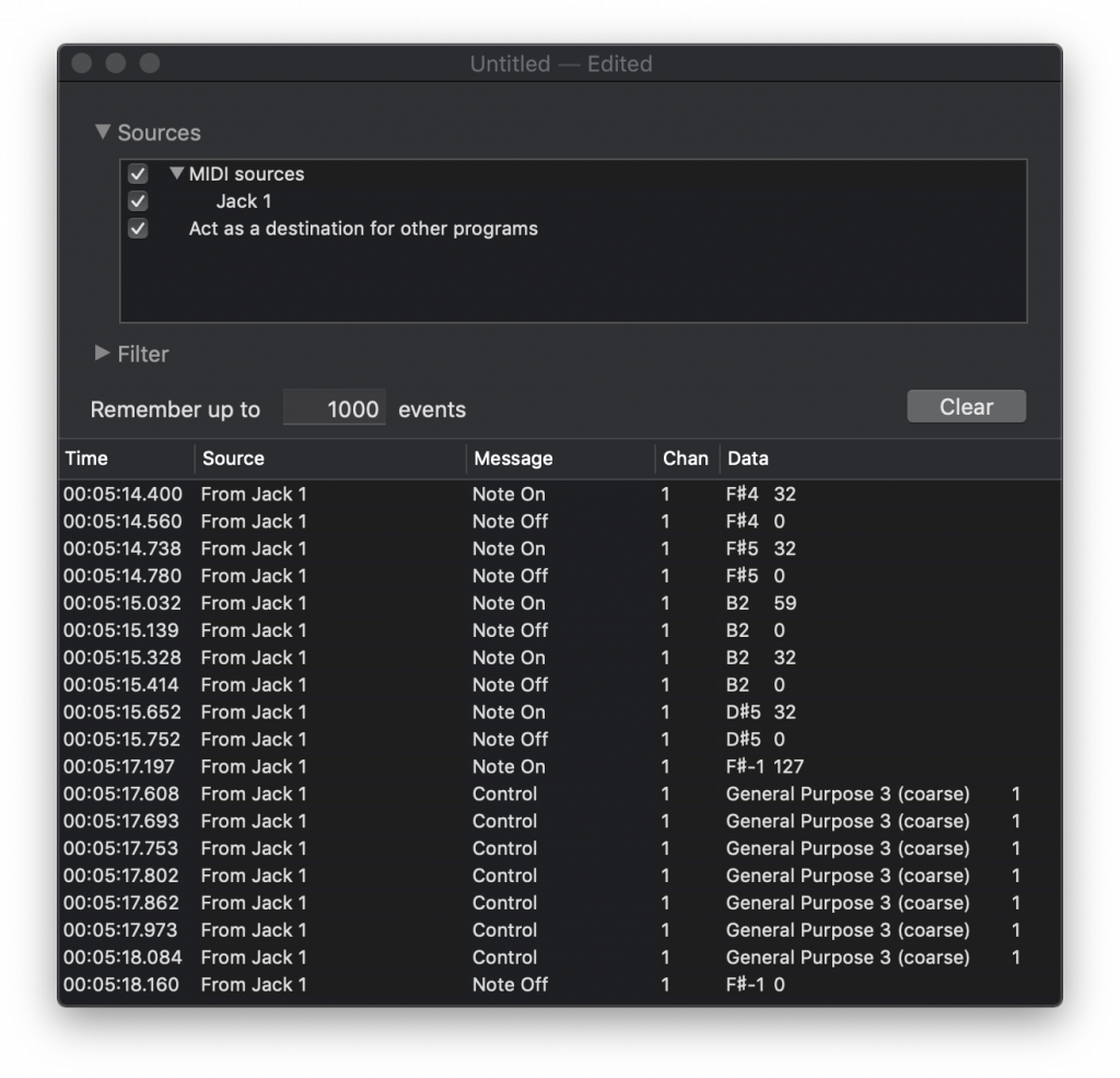
This continues the journey of reverse engineering how the Fire is controlled over MIDI and deals with illuminating the buttons and pads. Lighting the Fire Having done nothing out of the ordinary for the input side, it’s time to use experience to map the output side and see if we can get anything to light […]
article 2 has the info you need

This continues the journey of analysing how the Akai Fire is controlled over MIDI and deals with the OLED display. The OLED is a challenge! Looking at the OLED, it’s small at 128×64 pixels, with each pixel being taller than it is wide. But here’s the proof that you can write to the OLED! As […]
you can even write stuff to the oled display. neat!!
 prisma charm
Does anyone know if https://docs.rs/soloud/0.2.3/soloud/ works with adafruit's MAX98357? (Sorry if this isn't the right server for this)
API documentation for the Rust soloud crate.
 cursive anchor
prisma charm
Does anyone know if https://docs.rs/soloud/0.2.3/soloud/ works with adafruit's M...
cursive anchor
prisma charm
Does anyone know if https://docs.rs/soloud/0.2.3/soloud/ works with adafruit's M...
Before I start waffling too much - what main board are you using? RPI? Arduino? ESP32x? is the Max device a chip that plan to solder/build a board for? or some 'audio dev board' that is 98357-based?
 tardy jetty
@cursive bear that seems odd -- I have a similar setup w four NeoTrellis boards and a Feather M4 and haven't needed to add pullups.
cursive bear
@tardy jetty I think I might have a defective Feather M4. I'm working with Adafruit customer service.
tardy jetty
@cursive bear ah, right on, sorry to hear it, but they will help you get it sorted out soon I'm sure.
 red grove
Hello everyone. Can I use the microphone the circuit playground express to record audio into a pi zero?
versed torrent
yes.. but the sample rate is about 9.5kHz
const int BUF_SIZE = 128;
int16_t samples[BUF_SIZE];
...
CircuitPlayground.mic.capture(samples, BUF_SIZE);
Ah, so I should go the arduino and not circuit python route then.
versed torrent
oh - dunno - I'm not as versed in the CP side
but the functionality is probably there
red grove
Very cool, thank you!
 winter stone
hello, I have a bunch of questions about using an Uno to drive about 100 LEDs
okay to just fire away in here?
cursive anchor
well, as this channel appears to be for questions about audio it might be better to post in a more relevant channel @winter stone ? 🤔 #help-with-projects ?
winter stone
okay I'm stupid I read it as Arduino xD
cursive anchor
heh 👍
winter stone
...however while I'm here...
Ideally my project will be able to respond to midi clock signal (tempo)
but... I think my biggest problems will be code-related as I have a midi interface that will be capable of sending tempo info - the arduino just needs to be able to receive it and respond accordingly...
so I'll probably get back to you guys when I inevitably hit this hurdle haha, thanks
cursive anchor
https://little-scale.blogspot.com/2011/08/how-to-deal-with-real-time-midi-beat.html
And be sure you want the MIDI timing and not some instrument/event timing (like drum beat)...
*I realise it may be different to your setup but extract the 'logic/approach' if applicable
winter stone
this already looks great, thankyou
tacit jay
The problem I'm thinking about solving at the moment is how to make cool looking modular parts that are using a Circuit Playground Express.
Because the ring of display lights would be pretty, and useful indicators.
I'm wondering how to make it more useful than just as a display.
versed torrent
those are great devices... i use them for all sorts of random jobs: clock divider... clock source... midi to cv.... hold i your hand 3axis to midi cc thing... etc!
there’s also a cool spectrograph sketch for it
shut whale
something i don't quite understand, what is the advantage of having a high impedance?
i suppose it has something to do with something called loading? yet again, i dont really understand the concept of it
dull basalt
@shut whale Although the moon is smaller, it is farther away.
Impedance doesn't matter much at all - it is a design feature of a component such as a speaker or microphone.
(SIDEBAR: An EE - Electical Engineer .. could properly explain why impedance matters - a lot! Why components are designed, partially, around their characteristic impedances.)
For audio output stages, 600 Ohms was typical, for vacuum tubes.
I know an audio output transformer was required for those. Couldn't do without it.
Speakers at some point became 8 Ohms impedance, as the most commonly found variety.
(I think headphones and microphones were both 600 Ohms around that time).
In general you are supposed to match impedances to get good power transfer.
With a dipole that you can change the feedpoint location on it (telescoping whips!) you move the feedpoint well off-center (about 2/3 the total length of the antenna) to adjust its impedance, when it is very close to the Earth.
As you raise it higher, the feedpoint migrates closer to the center. At some elevation, when reached, everything is balanced, and you feed it dead center.
If you don't do that, then even when you adjust the antenna for resonance, it won't load as well (less power will radiate). And any SWR meter attached will read higher than otherwise.
Audio power transfer isn't really all that different from radio transmission.
(I can get away with saying that, here, because a more knowledgeable person is unlikely to happen upon what I just said; but it's far from a good understanding of the situation. ;)
rich topaz
Hi all, recently i got MAX9812 Microphone Amplifier Board from aliexpress, just look interesting and i want to try it because i have some mic lying around, but i cant find any wiring/documents or anything how to connect it, and biggest question I have, what purpose that jack have? Can someone help me out? (link from where i buy it https://www.aliexpress.com/i/33050398385.html?spm=2114.12057483.0.0.312d6c745VJrLc)
Cheap Operational Amplifier Chips, Buy Quality Consumer Electronics Directly from China Suppliers:MAX9812 Microphone Amplifier Board Micro Speaker 3V/5V/12V Audio Voice Sound Board AMP DIY Electron Kit
Enjoy ✓Free Shipping Worldwide! ✓Limited Time Sale ✓Easy Return.
solemn flint
The jack appears to be for the microphone input, since it looks like the traces are connected to the MIC IN pins too.
 steep ingot
Hello, can anyone suggest an easy/compact way for the pi zero to record stereo audio with auto gain control?
obsidian cove
@steep ingot https://pinout.xyz/pinout/adc_pi_zero# 17 bits, 8 inputs! sounds impressive.. until you see the speed it runs at
8 channel Analogue to Digital Converter
 heady shuttle
I'm looking for a small breakout board that has audio mic in with a 3.5mm jack preferably TRRS. I want to use a phone earbud mic for hands-free operation. Either analog or I2S would work for my application. Ultimately, for the long term, it would be nice to have both audio in and audio out. I'm really surprised that this isn't a thing.
cursive anchor
dunno of a board of that specific spec @heady shuttle but I used this recently and worked a treat!
https://store.digilentinc.com/pmod-i2s2-stereo-audio-input-and-output/
perhaps a simple splitter for mic/audio would work? you could use a female => splitter so it can live inside an enclosure so from the users POV is a trrs? I've also used these for a similar thing (connecting to the TRRS of an asus tinkerboard)
you can get el cheapo clones of the latter on Amazon
*bear in mind I think the pmod is line level
glacial spruce
There's also this TRRS breakout https://www.adafruit.com/product/2915

One truth about working with audio is you always need the cable or adapter you don't have in your toolbox. That's why we love these terminal-block audio connectors so ...
 muted wind
Does anyone know of any methods to calculate a decibel value from a PDM microphone?
cursive anchor
@muted wind
if you mean dBFS then value = 20 * log10(abs(sample) / maxSampleValue) dBFS
where, for e.g if we had a 16-bit signed int representing our sample (-32767, 32767)
and maxSampleValue being 32767
or something like that 👀
muted wind
cursive anchor
<@!360397243645296640>
if you mean dBFS then `value = 20 * log10(abs(sample) /...
Yes, thank you.
 fiery mauve
is there a way to "link" or "remap" gpio ports in the arduino ide? im trying to get the pi to display on a M5stack and the cs pin and the r/s pins aren't easy to access
glacial spruce
Shouldn't need to remap ports, just specify the GPIOs you want to use for CS and R/S in the constructor
fiery mauve
im kinda a newb, so sorry if im understanding this wrong but according to the schematic:
https://m5stack.oss-cn-shenzhen.aliyuncs.com/resource/docs/schematic/Core/M5-Core-Schematic(20171206).pdf
the CS, RESET, and R/S pins are all hardwired to GPIO's I can't physically access... only via software. I was thinking of setting 3 GPIO pins that I can physically access as inputs and in my main loop set the CS/RESET and R/S pins according to the input GPIO's
basically i want the raspberry pi to hijack the M5Stack's LCD screen
glacial spruce
I'm sorry, I don't understand. It sounds like you either want to change the pin mapping, or reprogram GPIOs as passthroughs, or do some dynamic switching or something.
But "hardwired to GPIOs I can't physically access" confuses me. Does that mean they go to pins that aren't on the other connector?
fiery mauve
yeah the M5Stack has some headers for gpio pins i can easily access, but its limited. for example the RESET pin for the LCD is GPIO33 which doesn't have a header. I'm trying to avoid soldering onto the board itself. sorry for being unclear im kinda newb lol
wait im dsylexic or something this isnt the arduino channel
dull basalt
Idk if any of yall can help me but I am trying to make this new "soundbox" work for me. Im using 3W 8ohm speaker on a board and for whatever reason it wont allow for the full sound to play. It starts very faint and then suddenly gets loud (to the set volume preference). If I use the aux port however, It will sound just fine with no issues connected to an external speaker.
 crude fern
Hi there! I've got a weird linuxy problem, using several Adafruit Audio FX Boards (adafru.it/2217) where my multiple linux machines are unable to mount, or even detect these boards! From home machines (all linux) I might surmise that the boards are DEAD.. plug them in, see a green LED light up, but no auto-mount (as they're supposed to do) When I take them into work (all Windows) BOOM! There they are, mounted, files exposed. Does this sound weird to you?
My home (linux) machines have no trouble mounting USB-anything-else.. just can't mount these boards 😭
glacial spruce
That does sound weird. I wonder if they're using a different style master boot block, partition map, or filesystem type for which Linux needs a module enabled.
cursive anchor
@crude fern did you try both modes? not sure if/how this applies to adafruit board but from vs1000 datasheet think its set via resistor on gpio6)?
"When USB cable insertion is detected by the firmware, playing of the current file is stopped and USB handling code is started. The internal clock is configured to 4.0× 12 MHz = 48 MHz, the analog power is configured to 3.6 V, the USB peripheral is initialized, and the USB pull-up resistor is enabled.
If GPIO0_6 has a pull-up resistor, VS1000 appears as an USB Audio Device. If GPIO0_6 has a pull-down resistor, VS1000 appears as an USB Mass Storage Device."
just to see if its a particular mode or something else. Also try different cables/ports
also from product page it only calls out Windows? 😬
"Built in Mass Storage USB - Plug any micro USB cable into the Sound Board and your Windows computer, you can drag and drop your files right on as if it were a USB key"
cursive anchor
also wonder if you can format the drive in windows and retry? and perhaps change the usb descriptors if that is possible? 😬
might not be loading the right driver on nix
 pallid jacinth
Hello, I'm pretty novice to electronics but would like to get started with a synthesizer project. I happen to have Adafruit HUZZAH32 Feather board and I would like to connect it to UDA1334A to get sounds out. The problem is I can't figure out if that is actually possible, HUZZAH32 is said to have I2S but nowhere is written which pins are for it 🤔
cursive anchor
@pallid jacinth huzzah is based on esp32? I believe there are 2 i2s 'peripherals' on the esp32... meaning you configure which pins to route the signalling info to/from in code. check out the docs from espressif.
pallid jacinth
Hmm okay so it doesn't have dedicated I2S pins but any pin works. I thought it needed dedicated pins as many other microcontrollers had ones.
crude fern
@cursive anchor Yikes! (and thanks) I overlooked that Windows mention in the product page! I never heard of a Windows-only USB device, but that's how it's behaving. Now I wonder if a) there's a workaround, or b) the product page should have a bold "Windoze only" banner.. hmph! Until then I'll just borrow access to the machines at work for the files transfer parts.
glacial spruce
There is a Linux toolkit https://github.com/asymingt/vs1000d-linux

GitHub
A toolchain for programming the VS1000D in Linux. Contribute to asymingt/vs1000d-linux development by creating an account on GitHub.
glacial spruce
The manufacturer also offers an app note and Linux programming tool http://www.vlsi.fi/fileadmin/app_notes/vs1000_production.pdf
crude fern
@glacial spruce that's fabulous, thanks! (i ❤️ Adafruit!)
crude fern
@glacial spruce on following those links, it seems to be referring to an interface to program that chip.. which is WAY over my head, and (I think) not specific to that chip as found in the Audio FX Boards. My only hurdle is mounting the device, and reflashing the chip bootloader for linux seems like a looooong walk 😉 I would update/ tweak my linux boxes, if that was not too insane, but barring that, I'll just accept that I've stumbled across a Windows-only gadget, and I'll find a Windows box to transfer the sound files. How might I make a friendly suggestion to the product-page maintainers, to post a more visible NOTICE about this limitation?
 cold grove
I'm trying to drive a 2 watt speaker with the esp32
something is wrong here
do all the audio driver chips take a signal like this but smoother? there is pwm based audio I'm trying to hack a circuit that originally had an audio signal that was 380khz pwm
glacial spruce
I wouldn't expect a PWM output to look like that, but there could be other intervening circuitry, or oscilloscope ailasing or something
cold grove
glacial spruce
Looks weirdly quantized, and I don't know which circuitry would do that
cold grove
esp32 i2s driver is swapping each pair of samples somehow
if I pre-swap the bytes thats a lot of code to fix something I dont understand
glacial spruce
Could be big-endian vs little-endian
cold grove
hmm. for it to be an endian bug somewhere in the pipeline
everything is big endian, except the audio data is for some reason generated in little endian, but this is accounted for
the wav file is signed 16 bit stereo data, so each sample is 32 bits
i throw away 16 bits to make it mono, then throw away the LSB to make it 8 bit
then add a zero byte back, because i2s is a stereo protocol
it turns out that an audio driver chip can be driven with a regular audio signal, or by a 380khz pwm signal where the duty cycle is the sample
I thought it might not work if audio chips are designed for one or the other
versed torrent
I'm a little lost --- you are trying to send audio over i2s... you are sending it as a stereo pair of 8-bit samples, yes? And... er... what is concern about pwm encoding? That would be a choice of the conversion circuity downstream of the i2s connection - you shouldn't be sending pwm modulated signals over i2s (as far as I know)
also - 380kHz pwm to encode audio is going to have really low resolution or low sample rate... or both.
As for your signal vis-a-vis that waveform.... a) it looks like bit 2 (third lowest) is flipped... b) what sample rate are you targeting? c) are we looking at a scope of the digital values, or the output of the dac in the top image?
cold grove
the rpi outputs audio over a 380khz pwm
versed torrent
then where does i2s come into this?
cold grove
I'm driving an audio circuit designed for the rpi pwm audio using the esp32 dac
its working good now, I just swap every 2 bits and it looks like a smooth signal
can't say why I need to swap every 2 samples but it works
even programming a triangle wave showed razor steps like each 2 samples was swapped
versed torrent
AH! Okay - so the PWM output is just that - a PWM wave, and to turn that into audio the audio circuit would need to filter at somewhat below nyquist. That's fine - because you'd expect that two be lower than the nyquist of what you're doing with i2s
cold grove
the pwm driver is weird, because its also putting that pwm wave over to the speaker
yet it sounds the same as just a normal audio waveform
versed torrent
you mean directly?
cold grove
the audio driver just takes the signal and drives a speaker with it at 2 watts
versed torrent
no low pass filter (the "reconstruction" filter)? That's awful --- I mean, a physical speaker is, in effect, a low pass filter (mass can only move so fast)
cold grove
it doesnt convert the pwm to an audio signal, it already is the audio signal, that makes a speaker sound the same, just in a different way
versed torrent
BUT - without any real control over the ƒ of that filter, ick!
cold grove
there's an unavoidable pop when the pwm driver starts up, thats the only real difference in the signal types
maybe the pwm signal will cause more emitted radiation issues too
versed torrent
The pwm signal, if you did a fourier transform on it - would have the audio of the original music + a very strong components at the PWM rate ... technically a proper driver should filter that off
cold grove
before messing with this, I thought pwm audio was just approximating audio voltages using an rc filter on it
versed torrent
the same is true for the output of a DAC - that stair step you see is note the audio encoded by your samples... it still needs to be "reconstructed" by running it through a low pass filter at nyquist.
cold grove
not true, pwm audio is pwm on the speaker itself
versed torrent
the RC filter for a PWM is the reconstruction filter
cold grove
its basically a low pass filter if its down sampled to 24khz
versed torrent
well - it might well be amplified to the speaker itself - but that is a janky way to do it: It is relying on the speaker cone to be the filter
cold grove
its low pass filtered at the point that the audio data is made
versed torrent
yeah - just careful here... if you pipe that audio to other systems, rather than an attached speaker cone, you'll run into problems
cold grove
I'm surprised it worked at all, driving the speaker with a completely different type of signal
versed torrent
like your home stereo or your audio interface will hate that signal!
versed torrent
Well... it needn't... the signal out of the PWM approach does have the audio information there.... just has lots of higher frequency information as well.
The direct output of the DAC (without a reconstruction filter) is exactly the same: the audio + high frequency information.
While the high frequency information in both cases is different - in each it needs to be filtered off, and the filter off point is going to be the same: nyqist of the sample rate of the audio information.
cold grove
so a low pass filter would solve the "unavoidable" pop
versed torrent
The real difference is that the PWM approach, in practice, tends to be much noiser and less accurate.
cold grove
this is how rpi drives audio, and it sounds scratchy whenever the rpi makes a web call
versed torrent
The "pop" is DC offset. For that you need a high pass filter --- to "AC couple" the output
cold grove
its either causing jitter or wifi signal is affecting the speaker wires
or wifi power use is affecting the speaker driver
maybe there's a small ground voltage happening due to wifi power bursts
versed torrent
That sounds more like perhaps the RPi is failing to get data to the PWM counter in time... WiFi signals will not affect audio signals in wires, even PWM ones.
cold grove
yeah, a scope actually didn't show jitter in any instance I could see
versed torrent
A skipped sample in PWM is going to be a repetition of the last sample (because the width counter hasn't been updated) - probably hard to see in a scope. The PWM is generated from a HW counter, so there won't be jitter in time no matter what the power or CPU is doing.
cursive anchor
hi all - I'm looking for an off-the-shelf audio pre-amp 'module/board' specifically suited for instrument input (guitar). anyone know of anything out there? (it absolutely baffles me this sorta thing is not readily available 😫 ).
ideally run on 3.3 => 5v.
 fallen hound
cursive anchor
hi all - I'm looking for an off-the-shelf audio pre-amp 'module/board' specifica...
fallen hound
cursive anchor
hi all - I'm looking for an off-the-shelf audio pre-amp 'module/board' specifica...
The Kemo M040N Preamplifier could work. Unfortunately it runs on 9 to 24 volts.
Datasheet https://asset.conrad.com/media10/add/160267/c1/-/gl/000114987ML04/bedienungsanleitung-114987-kemo-m040n-vorverstaerker-baustein.pdf (in multiple languages)
cursive anchor
@fallen hound 🧐 hmmm 2-50mv input range might be problematic for guitar pickups which often run up to 500mv peak 😬 thanks though! most preamps (at least module type ones) always seem to target mics...
ive not seen many guitar/instrument specific ones that are not 'DIY' solutions which i wanted to avoid if possible
glacial spruce
Normally guitars have a volume control, or you could add one. It depends on how "DIY" you want.
void umbra
Are there any "stable" Theremins/kits available that are not so dependent on temperature/humidity to hold tuning? I have some old kits from about 20 years ago that are great, except I have to retune them constantly, even in the same day, if the temperature or humidity changes too much. I'd prefer analog, unless there's digital versions that sound as good as analog.
heady shuttle
@void umbra I ran across this a few weeks ago http://www.gaudi.ch/OpenTheremin/index.php/opentheremin-v3. I'm not sure how it sounds but I'd be there are video of people playing it. I was thinking that at somepoint I might make a board with the micro on it to do away with the arduino. At the time I was thinking about using an ESP32 but I want to wait and see if someone makes a board with the RPI RP2040 and adds Wifi and Bluetooth. Having this as a Bluetooth Audio device would be pretty awesome.
void umbra
Thanks! I've heard the Arduino-based ones and they don't really sound very good compared to the analog ones, but I'll keep that in mind.😁
 kind cedar
Hi!
I am trying to do a sound (any sound at all) with my pybadge LC.
It is supposed to have a buzzer that can play (bad quality) sound, but I get nothing when I try the tutorial here: https://learn.adafruit.com/circuitpython-essentials/circuitpython-audio-out
No error-message either.
Is there some obvious reason why it would not work? Or some example-project or tutorial for sound specific to the pybadge? I did not find anything yet...

 echo hedge
@kind cedar did you set SPEAKER_ENABLE?
kind cedar
not consciously. let me google on how to do / use it and try...
It worked! Thank you!
 paper oar
Is this a good way to make a piezzo speaker?
Ive been trying to make it buzz at 440hz but nothing is working
With a dds algorithm
And an arduino
Serial plotter is making weird graphs as well. This is updated af the speed of the pwm signal
Slower updates of the graphs results in this
glacial spruce
@paper oar I'm not sure what the "~3" means in your diagram, but if it's 3V logic, that probably won't work.
paper oar
its OC2B
PD3
I should probably upload my code, buts its late rn so I wont clutter the channel
 chrome tinsel
Hi guys. I'm playing with the feather M4 express and a stemma speaker. There is something weird happening where sometimes after playing the mp3 file, there is a weird noise playing. like a high note going to a low not. kind of line a laser plaster sound FX
what causes that ?
all I got it a loop that wait for a command through I2C to play the sound.
and then when I send the command it plays the mp3 file and then half a second later that weird sound plays
chrome tinsel
So I just realised that it does it even without playing the audio. Just starting the script, it does it a few seconds after
 chrome tinsel
I just stripped all the code and kept the sound part. if I just load the mp3 file and play it, its fine. if I put it in a loop and play the file every 5 seconds or whatever, that noise happen after each loop.
dull basalt
in a fictional pseudo-code:
loop() {
  gate_audio_on()
  single_loop_iteration()
  gate_audio_off()
}
Cheap 2-way radios (CB for example; also 'scanners') tend to have a squelch circuit that isn't properly gated open and shut, so it makes a loud speaker noise when the squelch gates open (by a strong incoming signal).
chrome tinsel
Is there something like that with the audioio in circuitpython? An audio gate?
dull basalt
@chrome tinsel I don't know!
chrome tinsel
So it seems to be when I set audioio.AudioOut(board.A1) that causes the issue. If I just run a script that plays an mp3 file, it ends before it gets todo that noise. but if I put it in a loop, OR it set a time.sleep, it will do it.
chrome tinsel
found the solution. I had to use deinit() everytime I run the clip.
glacial spruce
I had been following along, but didn't have anything useful to offer, thanks for letting us know the solution!
 livid sorrel
I had someone asking me about an issue with the audio fx board suddenly not being recognised when plugged into a computer that previously recognised it - reading up, it seems like there's been a few reports so thought I'd ask if anyone had seen it resolved on here at all?
chrome tinsel
glacial spruce
I had been following along, but didn't have anything useful to offer, thanks for...
no problem. here's the issue I opened were ladyada explained what the problem was.
what Im working on requires a loop that waits for a request through I2C and depending on what it recieves it will play a specific sound FX. But the issue was that the AudioOut was initialized but it would not stay up or active while waiting for something. So what I just do is I created a function that initialise AudioOut, play the sound FX and deinit() once the clip is done playing.
def playAudio(clip):
    with AudioOut(board.A1) as a:
        print("playing")
        a.play(clip)
        while a.playing:
          pass
        print("stopped")
        a.deinit()
@chrome tinsel thanks - I probably should have added that the issue I was asked about is where the audiofx card was working and playing samples fine, but just suddenly stopped being detected as a USB device when connected to the computer; meaning that samples can't be added. The issue was described as being similar to this: https://forums.adafruit.com/viewtopic.php?f=19&p=729482

 echo hedge
got it going. had to clock it fast enough
 wraith egret
For my project I am thinking to use the Bluefruit Feather Sense (for the sensors and BLE...), but I see it has no DAC. However, the board supports audiocore, audiobusio, and audiopwmio per the circuitpython support matrix. Would I be able to easily play WAV files using a breakout I2C or I2S DAC?
or would I be better off adding BLE/gryo modules to a board with an onboard DAC, like the M4 express (and audioio support)?
wraith egret
sooo.. I phrased this question as "something I will do" because I was embarrassed I already bought the Feather Sense and was trying to get audio playing (I should have read the docs before buying!)
but.
following the learn instructions here

Adafruit Learning System
A nice and fully-featured I2S stereo DAC for you!
It says that it only works with M0 and M4 boards
but it works with the Feather Sense (nRF5284) too, I just changed
audio = audiobusio.I2SOut(board.D1, board.D0, board.D9)
to
audio = audiobusio.I2SOut(board.TX, board.RX, board.D9)
and wired it up per the Fritzing diagram for the M0 Express. maybe obvious to you guys, but it took me a little bit of thinking 😛
dull basalt
The documentation is a snapshot in time when it was new.
They're not necessarily going back there to update it when new support was added (or a new board comes out).
Figuring stuff out is a survival skill. ;)
 cunning frigate
I've been interested in studying infra-sound, and actually found an amazing scholarly paper on the use of microcontrollers to study it. But the paper doesn't seem to have published the exact schematics of the build, just has great pictures and stuff. Does anyone have any tips on getting more info on the build such as a circuit diagram, or I higher detailed parts list or something? I feel so close but so far =/ https://escholarship.org/uc/item/49j4h509#main

Author(s): Bergren, Steven; Latino, Carl D; Varnon, Christopher A; Abramson, Charles I | Abstract: The purpose of this project was to create a device to detect infrasound communication from elephants. The device was designed and prototyped to be capable of monitoring an input signal for infrasound. If infrasound is detected, an audible alarm is ...
cursive anchor
@cunning frigate ask the author nicely?
https://escholarship.org/uc/item/49j4h509#author
most people would be flattered at the interest and would happily share 🙂
Author(s): Bergren, Steven; Latino, Carl D; Varnon, Christopher A; Abramson, Charles I | Abstract: The purpose of this project was to create a device to detect infrasound communication from elephants. The device was designed and prototyped to be capable of monitoring an input signal for infrasound. If infrasound is detected, an audible alarm is ...
cunning frigate
Good point @cursive anchor though I had trouble getting,Steven Bergren's contact info it seems that stuff didn't make it into the journal and their university website is a little clunky to get info from. I'm still digging into the issue though and wondered since they mentioned "Geophone" as their sensor module (and mentioned nothing else around those specifics) I wonder if I should be asking the community more generally how does one convert data from a Geophone (10hz - 300hz) signals into a graph (perhaps PCM data?) that can be further analyzed by, say, Audacity/ Python processing. I found a dev board that seemed to make it easier (I'm really a huge h/w noob and need all the easiness possible) but it seems the manufacturer Protocenter doesn't make them anymore. https://github.com/Protocentral/openPressure

GitHub
OpenPressure combines an ADS1220 24-bit ADC and a SAMD21 microcontroller to make a complete 24-bit, high precision pressure and temperature sensor interface. - Protocentral/openPressure
cursive anchor
tip: he's on linkedin 😉
cunning frigate
ooh, I will open those links then, haha, I assumed it was a super common name
err.. do you know which one he was? I only see the CEO
ah, thanks! msg sent, I hope he's super nice! 😄
void umbra
Is there a simple way to visualize a sound wave (e.g. from an MP3 file) to a SVG or similar vector-based graphics file? This has been suggested, but it's got quite a learning curve. https://github.com/bbc/audiowaveform

GitHub
C++ program to generate waveform data and render waveform images from audio files - bbc/audiowaveform
cunning frigate
I always reach for Python first with that kinda stuff: https://www.google.com/search?q=python+audio+signal+processing&rlz=1C5CHFA_enUS891US891&oq=python+audio+signal+&aqs=chrome.0.0j69i57j0l2j0i22i30l4.7103j0j7&sourceid=chrome&ie=UTF-8 Check the illinois.edu hit, it's a for-sure good one
also, Audacity is the "spreed sheet app of the signal processing world" imo, so if you're just poking around sound, you might want to use it first if screenshots will help get things started
 ruby vine
is there anyway i can make a headphone jack behave like a mic jack so i can listen to it in windows
cunning frigate
some headphone jacks on sound cards are actually those 4-pin headset jacks and so you could use a headset with them just fine out of the box, but those cheap usb sound cards are usually pretty handy to just have around: https://www.amazon.com/UGREEN-External-Headphone-Microphone-Desktops/dp/B01N905VOY/ref=sr_1_5?dchild=1&keywords=usb+sound+card&qid=1614192168&sr=8-5
 supple vortex
I'd like to buy this sound board
https://www.adafruit.com/product/2217 and I need some way to trigger all the
sounds with some kind of wireless remote instead of tactile buttons. Can anyone tell me how I could do this?

Would you like to add audio/sound effects to your next project, without an Arduino+Shield? Or maybe you don't even know how to use microcontrollers, you just want to make a sound play ...
cursive anchor
triggers become pins on your micro and just fire them off to play the files? as for wifi either use your micro's wifi or a wifi board, create some basic REST server with an endpoint /play/:id which fires the corresponding pin and thus plays that file? @supple vortex