#help-with-audio
1 messages · Page 7 of 1
 dull basalt
Essentially, what is wanted is a 'remote' means to switch, when the physical distance is much beyond 8-12 inches.
Long lines should generally carry signals. ;)
 grand lance
so it might need a signal booster of sorts?
dull basalt
I don't know (falling asleep here, typical for me late afternoon, only 9 hrs or so from waking in the morning).
I was thinking about like using i2c to control PCF8574 port expander. ;)
Then maybe a transistor follower off of that.
Generally it's not good to send a weak signal over a long line.
If you try to make up for a weak signal at the far end (by amplification) you tend to amplify the noise along with the desired signal.
The problem with multi-channel audio is that the human hearer will be able to notice different levels on different signals.
Like in radio, two stations may both have about the same low audio, and the rest of the stations (listening only) won't notice that very much.
But as soon as a very loud station joins in (third voice) the difference is dramatic, and everyone listening (maybe 14 people) all reach for their volume control at the same time. ;)
Because they'd turned up the gain to hear the soft voices, now the boomer comes in and it's overbearing.
 tall mango
Is there a way to take out higher frequencies from an analog audio signal? Would using a ceramic capacitor work?
 glacial spruce
Yeah, an RC filter with a series resistor and a parallel capacitor will do the job.
glacial spruce
@pallid latch I can't resist sharing this
 pallid latch
Unclean! 😄
 clear dove
hello guys, I had a cheap ~$20 sades headset for gaming/discord and decided to recently upgrade to a Cloud Alpha. Despite being like 5x the price, the cloud alpha's audio quality is far worse, quieter, and has a static noise in the background. Im suspecting its because the Sades USB drivers are better than my motherboard (Gigabyte - GA-H110M-A) and the cloud alphas are analog, I was wondering if there was anything I could do to at least fix the volume of my cloud alphas if not the quality and static noise as it is really quiet right now. If I try to boost my mic in settings it makes the static noise worse
cant really get a new mobo/sound card rn
glacial spruce
Hmm, I wonder if it's a cable pinout problem. Does your mobo have separate mic and headphone jacks, or combined? Does the Cloud Alpha have a combined plug or separate?
It could also be an impedance issue: the Cloud Alpha is 65Ω and headphone drivers generally are designed for a 4 - 32Ω load.
Also, have you tried unplugging the mic? If it's the source of the static, that might help.
clear dove
@glacial spruce My mobo has seperate ones which i combine into one with an adapter that came with the headset whcih only has one. I kinda really need the mic for talking to freinds
im not sure what u mean by unplug the mic
glacial spruce
I meant unplug the mic for debugging purposes: not permanently. My understanding is that the mic plugs into the headset and is removeable.
If you're using the adapter that came with it, it's likely not a pinout problem. So the volume could be a level or impedance issue (or both). The static issue could be mic feedback or something else.
clear dove
how coul;d i test the audio withoout the mic?
for levels i have these settings
without the +20 its unhearable
and its still quiet
glacial spruce
You can test the output audio without the mic (to see if the mic is the source of the static). I'm trying to figure out why you're getting loud static but a quiet mic signal. Sounds like something isn't connected right.
clear dove
output audio is pretty clear though?
sorry if im not understanding you
should i record and then remove the mic and play it?
glacial spruce
You said "and has a static noise in the background" and also "If I try to boost my mic in settings it makes the static noise worse". I was guessing you meant the headphone audio, but I could have guessed wrong.
clear dove
oh, what i meant was that when i record my voice there is a static sound and its really quiet
when im just listening to audio its wonderful
glacial spruce
Ah, it's a mic issue, not a headphone issue. The first thing I'd do is unplug all three of the mic connections and plug them back in, in case one of them has a bad connection.
glacial spruce
There's the connection where the mic plugs into the headset https://media.kingston.com/hyperx/key-features/hx-keyfeatures-headset-alpha-4-lg.jpg

 clear dove
oh i see what u mean
glacial spruce
There's the connection where the mic plug connects to the adapter, and there's where the adapter plugs into your mobo. That's 3.
clear dove
lol i feel like an idiot, there is still a bunch of static but at least its way louder now
thanks so much
unless you also have a solution for the static
without mic boost its still pretty quiet but thats whatever
glacial spruce
I'm guessing there's another problem that's causing the low mic signal, and when it's boosted, it boosts all the background noise along with it. There are several possible things that can cause that.
 mystic zephyr
Hey guys, I'm designing an 8 channel audio mixer and its going to have a amplified headphone output. Now as of now in my schematics I have all of the grounds just on one ground plane. Will it, and if so how badly will it add distortion or background noise if I leave it like this and don't isolate the audio signal fron the actual amplifier source itself? The amplifier circuit is being powered by +5v
Tag me if anyone answers!
glacial spruce
@mystic zephyr as long as you don't have ground loop issues, it should be fine
mystic zephyr
OK cool, thanks @glacial spruce
 marsh pendant
morning (at least where I'm at). I'm trying to wrap my head around how I can use the arduino tone function without using delays a-la blink without delay. I want to fit some simple melodies into a larger project and I'm trying to avoid using blocking code because the controller running the speaker is also going to run several LED strips.
I hobbled together a proof of concept sketch that uses concepts from the toneMelody example and a stack overflow post I found (my original from-scratch attempt failed hard).
This "works", but the melody is a bit jerky. the note durations sound off like the controller is stumbling a bit if that makes sense
Here's a vid of the poc: https://vimeo.com/341347859
and the sketch: https://github.com/chris-schmitz/tone-without-delay/blob/master/tone-without-delay.ino

GitHub
Working through tone without delay on arduino. Contribute to chris-schmitz/tone-without-delay development by creating an account on GitHub.
anyone see anything obvious that I'm doing wrong?
glacial spruce
You're doing a lot of unnecessary math, and the outputTone flag seems redundant, since there's more tone/no tone logic in the if under it.
marsh pendant
hmm, so like remove the if/else that's checking for outputTone and let the conditionals that check the intervals happen on the same level, right? Like line 56 and 69 can be at the same level b/c their interval checks can handle themselves?
and as far as unnecessary math, do you mean calculating the note durations?
vs just having an array of those durations that I pull from since those number will never change? (didn't think about that till just now)
glacial spruce
When using millis(), I like to call millis() once at the beginning of loop() and cache its value, and precalculate the times for the next operations to replace a bunch of subtractions with one addition: ```c
void
loop()
{
unsigned long curtime = millis();
if (curtime > timefornext) {
// do processing
timefornext = curtime + noteduration[i];
}
ooooh
nice!!
I just stopped for lunch so I'll try out those suggestions. Thanks 🙇
 hollow barn
@marsh pendant the notedurations look a bit strange. those are 'ths of a second? (in other words 4, 8, 8, 4, = 4th, 8th, 8th, 4th) it doesn't read instinctively, as I would assume an 8 is twice as long as a 4.
Instead, an 8 is half as long as a 4.
marsh pendant
@hollow barn sorry just seeing this. those are the note types, so they're divisions of a whole note. As the number goes up their size goes down
dull basalt
you seem to know a lot on audio programming @hollow barn
I'm assuming you must be one yourself?
hollow barn
@dull basalt No, I just know a lot about programming. If I knew more about music the fact that those were note lengths would've been obvious.
dull basalt
hence, are you a hardware programmer yourself, then? @hollow barn
hollow barn
@dull basalt Daytime job is Software Architect. Arduinos are for fun.
But I spent a decade as a C/C++ programmer. Most of what goes on in an Arduino is pretty straightforward.
hollow barn
@marsh pendant FYI, when I was looking at your code,
First, you advance thisNote BEFORE getting the noteduration, so you're using the duration of the wrong note, unless you put them in the noteDurations array off by 1.
Second, if you try you can do it with a lot fewer variables, and a bit simpler with something like:
    // not quite sure how long handling the lights took, make sure we
    // know what time it is.
    currentMillis = millis();

    // is it time to change
    if (currentMillis >= nextChange)
    {
        if (notePlaying)
        {
            millisUntilNextChange = pauseBetweenNotes;
            noTone(SPEAKER);
        else
        {
            millisUntilNextChange = 1000 / noteDurations[nextNote];
            if (melody[nextNote] != 0)
            {
                tone(SPEAKER, melody[nextNote]);
            }
            else
            {
                noTone(SPEAKER);
            }
            // ok, that note's handled, move to the next:
            nextNote++;
            // and if we're now playing note 7 (advanced to 8) , start over:
            if (nextNote > 7)
            {
                nextNote = 0;
            }
        }
        notePlaying = !notePlaying;
        nextChange = currentMillis + millisUntilNextChange
    }
A lot of what I'm doing is being clear about the variable names. For example, nextNote is what you called thisNote. thisNote is a bit inaccurate, as during most of the code, it's pointing to the next note that will be played, not the note being played now.
Also, nextChange is keeping track of the millis in the future when the note will end, or the pause between notes will end.
Naming variables is incredibly important.
Ah I think I caught the final bug in your code:
            if (thisNote < 8) // if 7, continue
            {
                thisNote++;  // increment 7 to 8
            }
            else
            {
                thisNote = 0;
            }

            // * figure out the duration for the new note
            noteDuration = 1000 / noteDurations[thisNote];
                // UH OH... what is noteDurations[8]; going to give us?
nice, thanks for the refactor. This def reads a lot easier than the example I was working from and modifying. thanks!
hollow barn
@marsh pendant If your audio's still off, you might want to look at capturing how far delayed you are any time you that fall into the note-change. Let's say that updating the LEDs sometimes takes 40 milliseconds. What would be cleaner would be to change the note early by half the delay, rather than always being late.
In the case above you'd consider it a match once you get within 20 milliseconds of the nextChange, with something like this:
unsigned long lateMillis = 0;
...
if (currentMillis >= nextChange)
{
    // if  we're late, and it's a new record for how late we were, capture that.
    lateMillis = lateMillis < (currentMillis - nextChange) ? currentMillis - nextChange : lateMillis;

...

    nextChange = currentMillis + millisUntilNextChange -  (lateMillis / 2) ;
cool. I'm in the middle of refactoring the code to move the procedural logic into a class. I incorporated a bunch of your suggestions. There's still a bit of troubleshooting I need to do with the class, (some internal state management at the end of a melody), but once I'm done with that and clean out the rest of the procedural version from the .ino file I'm going to circle back to incorporate this idea
all that said, the melody plays nicely through the melody once without delay at the moment 😃
marsh pendant
also also, status vid: https://vimeo.com/342811509

Not the greatest demo vid, but wanted to shoot it before getting back to work. I've started abstracting the tone without delay logic out to a class. There…
which is eventually going to get fit into this prototype: https://vimeo.com/342747547

Last week Terri gave the plinko board a paint job and I got a magic bullet through the game flow. Now all of the general steps of the game flow and the messaging…
it's super exciting b/c the sound effects are one of the last things I want to fit in before I call the prototype complete and start designing the final build 😃
dull basalt
best you present them on youtube rather, since A LOT more people watch that than Vimeo tbqh @marsh pendant
marsh pendant
true, I'm not too worried about audience just yet. I'm trying to build a backlog of content and b-roll footage for projects and leave youtube for the larger project overview vids
the hard part is finding time to do all of the video editing
I like using vimeo for all of the status and quick vids, I like their interface and apps better than youtube
but yeah, eventually the vids will end up on youtube
marsh pendant
@hollow barn Thanks again for your input. I finished my code abstraction for my tone-without-delay proof of concept. Between your suggestions and help from a couple of other people I got the proof of concept down to the point where I'm ready to fit it into the prototype.
Here's the proof of concept code: https://github.com/chris-schmitz/tone-without-delay
GitHub
Working through tone without delay on arduino. Contribute to chris-schmitz/tone-without-delay development by creating an account on GitHub.
and a vid of it (for the most part) working 😛 https://vimeo.com/343229038

I got tone without delay "working" before, but it was in a procedural script. The sketches for the prototype are getting big enough that I def don't…
 golden gorge
Need a small cap in series with that button.. the 'sometimes' that happens is surely button noise. er.. sorry.. Meant to say Parallel, not series. If it wasn't an interrupt, you could do debounce in software.
marsh pendant
@golden gorge cool, yeah I was considering coding in a debounce but I was running out of time before needing to start work so I went with an interrupt b/c the coding is quicker (the rotate function I had written was already a good ISR) .
Your comment about the capacitor is fantastic though because I understand what capacitors do, I've used them when following along with tutorials, but I still have a hard time understanding when one is called for in a project I'm working on, where it should go, and what size I need.
If you have the time, could you explain a bit more about how I would fit it in and how I would determine the cap size I need?
it would be super helpful
glacial spruce
I'd try a small capacitor, maybe a common 100nF or so (the value depends on the value of the pullup resistor and the amount of debounce time you want). It goes in parallel with the switch, which means the two leads of the capacitor are connected to the two pins of the switch.
marsh pendant
ok cool, so conceptually
the capacitor is acting like a well of electrons that fills up (absorbing all of the noise) when the button isn't being pressed, this way there's no voltage flowing to the jumper going to the input GPIO pin for the button.
When the button is pressed the electrons flow out of the capacitor and through the jumper instead of the pullup resistor.
Then once the button is released the electrons collect again in the capacitor.
Am I thinking about that correct?
(trying to make sure I understand the why as well as the how)
glacial spruce
Err, not quite I think. I'm going to stick with "classic" current flow instead of (negative) electron flow for clarity. When the button is not pressed, current flows through the pull-up resistor into the capacitor, charging it to the supply voltage, which is what the I/O pin sees. When the button is pressed, it's basically a short circuit, a large current flow discharges the capacitor quickly, and the I/O pin sees a low voltage. Then as the contacts bounce, the pull-up resistor charges the capacitor to a small value, then the next bounce discharges it again: the voltage bobbles back and forth quickly at a low level, which the chip continues to interpret as "zero". Finally the contacts stop bouncing and stay closed, holding the capacitor voltage at zero.
When the switch is released, the pull-up resistor starts charging the capacitor again, but for a few bounces, it sticks around near zero as before. When the contacts stay open, the resistor recharges the capacitor, and then the I/O pin reads a "one" again.
marsh pendant
ah, ok. I think I get it. I feel like I'll need to read over that and experiment a bit to really grok it
thanks for explaining that 🙇
 velvet saffron
hopefully this is a good place to ask, this question. I am using the Arduino IDE with PyPortal and am able to run the self_test (https://learn.adafruit.com/adafruit-pyportal/arduino-test) and hear the coin.h sound.
I'd like to play other sounds now.
What is the best way to play a .wav file on the SD card from Arduino using the PyPortal?
 stray narwhal
Gotta be in Arduino? PyPortal in CircuitPython has a play_file function.
If Arduino is a requirement, there's code at the end of your page that shows analogWrites of unsigned 16-bit integers for each sample of the overall audio. Then it's just a matter of reading the SD card wav file into an array of 16-bit values.
velvet saffron
Yeah, I had been using the play_file() function in circuuitPython, but the response time was slower than wanted for graphics. Now that I am in Arduino the graphics reponse time is good enough but now I have to figure out audio. I was hoping there was an Adafruit Arduino playFile() built in for PyPortal .
I'll google 'reading the SD card wav file into an array of 16-bit values' next, unless someone knows of a library.
thanks
stray narwhal
CircuitPython 4.1 beta vastly improved display speed, if that's all that was the issue.
velvet saffron
oh cool. I was using 4.0 when I switched. I'll take another look at CircuitPython if I can't get reading the .wav file from Arduino working.
dull basalt
How can I create a function that writes exactly one cycle of my waveform? Is it as simple as using analogWrite(); and use a for loop to go through each value of my table?
glacial spruce
If you're using a DAC (instead of PWM) yeah, that would work. You'll need a little code to send the samples at a fixed speed, but it's not too tough.
 high junco
Any library available for software filtering of pdm input of MEMS microphone? Or perhaps a RC hardware filter is a recommended option (noting that I'm currently using the cpx directly and as of yet do not need a breadboard given the integrated capabilities of the device.).
Using a Circuit Playground Express (cpx). I'm primarily interested in detecting tones, but any reference material on managing audio input beyond "there's a sound" would be meaningful. A complete solution would be include being able to write audio files (though I don't need that personally).
All projects/tutorials that I've found for cpx audio input simply detect whether there's a sound event, by simply summing or calculating RMS to get a value more or less representing audio magnitude. I'm concluding that I'll want to create a custom software-based FIR or CIC filter by porting implementations for other platforms, since none exist for Circuit Playground Express.
I'll appreciate any thoughts or pointers.
Then, of course, I'll need FFT.
glacial spruce
There's a fork of Paul's excellent Audio library that supports AdaFruit boards https://github.com/adafruit/Audio. You can also use hardware filtering with op-amps or a dedicated spectrum analyzer chip like an MSGEQ7.
high junco
I had been reading Paul's code. This is very encouraging.
high junco
Thanks for the reply, and the tip on MSGEQ7.
dull basalt
I have a project idea
I'll go for Python
I want to make a GUI that can record a clip of my microphone, buffer the audio data, then process it (amplify by a couple decibels), and play it through a virtual audio cable
However, I want the cable to have 2 inputs, and one output, is this possible?
So I can configure Discord to use the cable output as an audio input, but let me speak through my microphone, and also play the audio from the program
Simultaneously
dull basalt
@Alejandro sound's like it's possible, but you should also patent that idea too, so that no one else steals it: https://www.lotempiolaw.com/2015/08/blog-2/patent-your-idea-for-free/

Looking to save money and file a patent yourself? Filing a patent yourself without seeking legal advice can potentially put your invention at risk.
Thanks for the..umm, suggestion. But I'm not about that life
dull basalt
you really want people to steal your ideas without giving you credit? @dull basalt
This isn’t a professional idea
I’m just having some fun
pallid latch
Grabbing patents is pretty much the antitheses of all things Maker. 🤷
dull basalt
@pallid latch is correct nonetheless js @dull basalt
glacial spruce
I got my name listed on a patent filed by some people I was working for. I'm unsure how I feel about it.
pallid latch
I strategically have been too busy on the days where they come in and try to get us to file patents.
dull basalt
Oh
But, seriously, I'd like to make something like this
I installed VB audio cable
But I don't know how to explain what I want properly
I want Discord to pick up input from both my mic, and from an application
Simultaneously
glacial spruce
Something like https://rogueamoeba.com/loopback/?
dull basalt
Yes
That's for Mac
I want to make this myself
Sounds fun
GUI could be something like this
Record the audio > Buffer the data > Amplify it by about 50 to 100 decibels (Allow clipping) > Buffer the edited data.
stray narwhal
At 100 dB, it's all clipping (gone from light leaf rustling to jackhammer, or from conversation to jet engine). Even at 50 dB, it's gone from normal conversation to jackhammer (https://en.wikipedia.org/wiki/Sound_pressure#Examples_of_sound_pressure). But if you've got the original mic and the heavily amplified mic going into the same place, the heavily amplified mic is going to overwhelm the original.
Sound pressure or acoustic pressure is the local pressure deviation from the ambient (average or equilibrium) atmospheric pressure, caused by a sound wave. In air, sound pressure can be measured using a microphone, and in water with a hydrophone. The SI unit of sound pressure...
dull basalt
That’s what I want
Hehehehehehehe....
I need a place to start
Do you guys know of Python libraries that can record from a source, manipulate, and play the sound data into a destination?
The diagrams I made are exactly what I want
stray narwhal
But what's the point of the arrow directly connecting the mic and the Discord?
dull basalt
The arrow represents connection, of course
I want Discord to be able to hear both the application, and the mic
@stray narwhal
 grim shore
I think he's asking you to take a step back. What is the use case for having the microphone direct audio go to Discord, and having the audio go through your recording/buggering/amplification app and go to Discord?
dull basalt
Messing with my friends
grim shore
Understanding the kinds of things you envision using it for will help others understand your requirements, and guide you to the right technical solution
dull basalt
And a learning experience for me
grim shore
Okay, so as a first learning step, do you have an app that records audio from a mic?
Or an app that sends audio to Discord?
dull basalt
I want to be in a voice call, and while talking, re-route my mic input to the app, then back to discord, have the app amplify it, and then let me play it into the mic input
grim shore
If you don't, consider trying those first. A soundboard app that sends various clips to Discord audio would be a great first step to understanding that piece of it.
dull basalt
I have Audacity
grim shore
Does Audacity allow you to send sound to Discord voice?
dull basalt
I have figured out how to record my mic, then mess with the audio, and use a virtual audio cable to play it to discord
Yes
grim shore
Okay, so what does that not give you?
dull basalt
But it’s a hassle. I have to go to my voice settings and set the audio device to the virtual cable
While it’s in that state, my actual microphone input is not active
grim shore
so what you really want is a virtual switchbox
grim shore
something that sits in your computer and appears to be a sound device (like the virtual audio cable) but ALSO allows you to tie in another sound device(s)
and then mix them in and out
grim shore
so a switchbox/virtual mixer kind of thign
dull basalt
I just want the hassle solved
I don’t want to have to mess with the settings every time
grim shore
Take a look at this Reddit thread and see if any of the solutions talked about there may help: https://www.reddit.com/r/Twitch/comments/5zzsic/virtual_mixers_and_windows_10/
dull basalt
What would be fantastic would be to find a way to route audio output into the microphone, sort of a hijacky sort of thing
grim shore
In particular Voice Meeter sounds like exactly what you want, multiple sources of input/output
Assuming you're on Windows
grim shore
VoiceMeeter Virtual Audio Device Mixer by V.Burel
dull basalt
Definitely looking into it
grim shore
hope that helps!
grim shore
I work in IT and I see it all the time -- we get so wrapped up on technology, we forget to step back and say, "what problem am I actually trying to solve?" 😃
Made a decent living for years as a consultant who does that "step-back" process.
dull basalt
Ah
 red rain
hello, what are the best boards for making an audio computer, compatible with pure data?
I know raspberry Pi is popular, but there were some other, and I forgot the names.
glacial spruce
The Teensy boards have some solid audio capability, after that it's DSP chips and the like.
red rain
Are there still some boards that adafruit isn't covering?
glacial spruce
I'll admit I'm a little confused. I'm unsure what you mean by "audio computer", nor "compatible with pure data", nor "adafruit isn't covering".
red rain
 audio computer refference "OrGaNeLLe" ♪♫ - https://www.critterandguitari.com/organelle ,
compatible with PureData aka PD - http://puredata.info/ , able to reed and run a PD patch
stray narwhal
Pretty sure that's often called a synthesizer. Not a musician, so can't say for certain.
red rain
An audio computer is wider in functions and processing, than a simple synth
I think I found the one I had in mind, it's still on a kickstarter though, I'll have to see if it's even out yet : https://www.kickstarter.com/projects/423153472/bela-an-embedded-platform-for-low-latency-interact

Bela is an open-source embedded platform for real-time, ultra-low-latency audio and sensor processing on the BeagleBone Black.
stray narwhal
Don't think any of the main maker/electronics vendors have much for that application, then. At least nothing as polished as a final assembly. Just the lower-level microcontrollers, audio boards, etc.
red rain
which is exactly what the Bella is.
And it's what I'm looking for, something like raspberry Pi, but maybe better?
stray narwhal
Ok, but you can buy the Bela since the last few years, and a mini since last year. https://shop.bela.io/starter-kit -- it's a BeagleBone Black with maybe some other boards for better ADC/DAC, and some Linux customizations to reduce latency. A Pi probably isn't going to outperform a BeagleBone.

The Bela Starter Kit contains everything you need to get up and running with Bela:1 Bela Cape1 BeagleBone Black rev C2 x 3.5mm jack audio adapter cables1 Mini USB cableLatest image flashed on the eMMC of the BeagleBone (no need for SD to get started)This price includes free 1...
red rain
ty!
 weary sentinel
This is a slightly different kind of request, so I'm not sure anyone can help. I hope so. I'm trying to build a sound-activated camera, but only for loud sounds. I need to interpret SPH0645 digital output as decibels. I read the data sheet, which was remarkably unhelpful. Does anyone know how to do that mapping?
glacial spruce
You'd probably have to preprocess the data to extract the parameter you're interested in (peak, average, whatever), then compare the resulting value. The actual decibel reading will depend on the enclosure, so your best bet is to make a corresponding noise and measure the resulting value, then use that as a detection threshold (the same sort of approach we tend to use in capacitive touch sensors, which are wildly dependent on their installation).
weary sentinel
@glacial spruce I can do that pretty easily! Thanks for the tip. I was thinking like a theoretical physicist ("there must be a formula for this") instead of an experimental physicist ("got a question, go measure something.").
glacial spruce
Yeah, the theoretical approach is unwieldy in this sort of situation (compute the diffraction, absorption, and impedance matching characteristics of the mounting cavity and focussing effects where the mic port is mounted, multiply SPL by that, convert to PSI, convert to deflection, convert to voltage, convert to digits, extract logarithm, etc.)
weary sentinel
Yeah.... ick. I should have thought of that.
glacial spruce
I used to work in a particle physics lab, and was impressed by the great divide between the theoretical physicists and the experimental ones. Since I maintained lab equipment, I mostly worked with the experimental group, but it was interesting to see how they'd try to figure out how to actually implement and measure the pages of dense equations produced by the theoretical guys.
weary sentinel
Me too (FermiLab) but that was very very long ago. I'm more theoretical than experimental, but the experimentalists are amazing. So are the machine engineers. "You built superconducting magnets to WHAT precision?" Mind-blowing.
glacial spruce
My tasks for my job vary a good bit, but since I kind of enjoy math, the mathy assignments tend to come my way. This is something I'm working on today.
weary sentinel
Cool. My math has gotten WAY too rusty, except statistics and machine learning.
When I first looked at that my thought was, "that's a nice projection. I wonder what software they used."
glacial spruce
I must say, I'm very fond of Graphing Calculator.
weary sentinel
Ooooooh. Pretty. That looks way easier than breaking out ggplot2.
glacial spruce
The Lite version (which I'm using) is free. https://www.pacifict.com/Products.html
To give an illustration of how usable it is, I banged in that equation and graphed it in the 4 minutes from the time I posted the screen grab of the LoG page to the time I posted the resulting 3D graph (including the slider for changing σ).
weary sentinel
That looks really sweet! I'll still have to revert to R or Python for processing real data, but that looks good. Does it handle calculations on non-Euclidian surfaces? I didn't see that mentioned.
glacial spruce
I don't remember offhand. I remember using it when I was in school to get a good hands-on understanding of how inequalities really worked. Yeah, I'll end up converting the equation to Python for use in generating convolution kernels to emphasize vasculature in chest X-rays before handing them off to Tensorflow to try to automatically identify pneumothorax (yeah, my job is particularly fun this week).
pallid latch
Also, jupyter is pretty neat
glacial spruce
Basically we're entering this contest https://www.kaggle.com/c/siim-acr-pneumothorax-segmentation
weary sentinel
Nice! I can't actually say what I'm working on, unfortunately. (My employer would frown on that.)
glacial spruce
One friend of mine can now talk about what she's been building
weary sentinel
Ooooh that's gorgeous.
 uneven raven
That is amazing!
 scenic heart
Hi! I have an Adafruit Circuit Playground Classic and I am trying to import mp3 and wav files on there. Is that possible?
scenic heart
bump
glacial spruce
I don't think it has the CPU horsepower to decode MP3 files, but there are chips that can do that for you. I'm not quite sure what you mean by "import" here. You could store them on an SD card or a flash chip, I suppose.
 fickle leaf
@scenic heart Mike Barela wrote a few learn guides for working with sound files. Here's one that may be helpful. https://learn.adafruit.com/make-it-sound/music-and-sound-in-makecode-2

Adafruit Learning System
Add sound quickly to your Circuit Playground Express and Crickit Projects
glacial spruce
That's for the Express: the original question was about the Classic.
scenic heart
@fickle leaf I appreciate your help on this but yeah, what madbodger said, my question is about the classic, as this one doesn't support the classic 😦
fickle leaf
Ah, missed that detail.
 noble prism
Hiya! Got a quick question about connecting an analog amplifier to one of the DACs on an Itsy Bitsy M4 Express. I'm hoping to play back some WAV files via CircuitPython's audioio.WaveFile on a traditional speaker. I'm concerned about passing that analog signal into https://www.adafruit.com/product/2130 (or similar), due to the DC offset. Would that amplifier tolerate AC signals from 0 to 3.3V?

This super small mono amplifier is surprisingly powerful - able to deliver up to 2.5 Watts into 4-8 ohm impedance speakers. Inside the miniature chip is a class D controller, able to run ...
glacial spruce
It looks like that breakout board includes decoupling capacitors, so it won't see the DC offset at all, but also won't have frequency response down to DC (which is rarely an issue).
noble prism
'won't have frequency response down to DC'... meaning it would not be able to support ridiculously high frequencies?
glacial spruce
High frequencies are not affected by the capacitors, just low frequencies. There will be a high frequency limit as well, but it comes from other factors.
You can think of DC as the lowest possible frequency of zero hertz.
noble prism
Got it. Based on your mention of decoupling capacitors, I was able to find this: https://electronics.stackexchange.com/a/304946

Electrical Engineering Stack Exchange
I have a sine wave with a minimum peak of -2.5V and a maximum peak of 2.5V. I want to add a DC offset of 2.5V (using a separate power supply so no positive clamper) in order to get a sine wave betw...
Awesome. Thanks for your help @glacial spruce! I will move forward with initial tests via a piezo & then attempt to amplify that signal with https://www.adafruit.com/product/2130. The decoupling cap notes are very helpful indeed!
 wispy mortar
Similar to yesnoio a couple weeks ago, I'm driving a https://www.adafruit.com/product/2130 -- but in this case, from a 3.3v PWM digital signal. It sounds like when my samples are loud they are being clipped. And adjusting the volume trimmer doesn't seem to do much. Any advice? Do I need something like a RC filter, resistive divider, .... ? I'm going to go 'scope my PWM waveforms next, because the problem could be on my software side too/also...
This super small mono amplifier is surprisingly powerful - able to deliver up to 2.5 Watts into 4-8 ohm impedance speakers. Inside the miniature chip is a class D controller, able to run ...
my signal is on A+ and I've left A- floating. Grounding A- seemed to stop all sound.
actually, the scope does make it look like it might be a bug on the output side... hm.
audio pwm glitch
wispy mortar
OK, yes, that gitch was a bug about understanding the range of PWM values that still gives at least 1 period low and 1 period high.
 lunar merlin
hello. I'm trying to have my Pi Zero play a sound file at start up and I've thought I could just run the speaker test thing with a different wav file, but apparently my wav file is not correct. from what I've gathered they are both 48kHz, mono, Microsoft PCM format
(it's part of a gift/project, I dont want to get into coding just want it to play a sound and push a picture onto the screen so that the person who gets its can see its doing something/capabilities)
maybe other easy options to play a short audio file with a command line?
using the adafruit-max98357-i2s-class-d-mono-amp with a tiny speaker. the regular front-center.wav file test works
lunar merlin
well. found an mp3 player that works with my files so I guess it's sorted
 grave gale
Quick question. If I wanted to hook an 8 ohm speaker to feather music maker what happens if the speaker is more than 1 watt? The speakers I am considering are not powered and have a power handling of 50 watts (200 max). Will the audio just be too quiet due to too little power or will this damage the board?
glacial spruce
Should be fine. In fact, large speakers are often more efficient than small ones, so you may get more volume from your wattage.
grave gale
Thanks for clarifying that. I tried one as a test and they sound pretty good on my feather ...
 brittle vigil
I'm wondering, can the featherwing music maker (w/ amp) be used with circuitpython (it's hooked up to a feather m4 express, also hooked up to a neotrellis rgb) ? I can't find any example code :(
glacial spruce
Yeah, CircuitPython supports the VS1053: https://github.com/adafruit/Adafruit_CircuitPython_VS1053/blob/master/examples/vs1053_simpletest.py
Some documentation here as well https://circuitpython.readthedocs.io/projects/vs1053/en/latest/api.html
 raven goblet

Super User
Motivation
I occasionally stream with OBS and have my own virtual audio mixer (Voicemeeter Potato),
Since I had multiple Drumpads collecting dust I figured in stead of buying an Elgato StreamDeck f...
brittle vigil
@glacial spruce yeah found that repo too a few hours later. But mp3 playback apparently is a no go. So had to hunt down arduino libraries for the NeoTrellis. I've made a first functional sketch which combines both the featherwing as the trellis. It has sound, lights and button presses, just not in a polished form yet.
glacial spruce
I've seen that a few times, A, B, and C can happen just fine but when you try to add D, the whole edifice crumbles and you have to tear into it to get things to all play nice together.
brittle vigil
It's part of the hobby I guess. But hey, I'm happy I could get it all come to life. The previous incarnation with a Trinket and seperate soundboard died and I never liked it. The stacking of feather and featherwing is far more elegant.
This time I should probably keep the whole contraption away from open windows in rainy weather 👀
 light crag
I want to know how you remove the hiss sound from cassette
glacial spruce
The usual approach is equalization (and, ideally pre-equalization) and noise gating. There are also commercial audio processors available that do that sort of thing.
 worn echo
I'm new to all of this stuff, im trying to make it so when I use the ir remote, it lets the current pass through two terminals so I can power a fan
I can't figure out how to make something that would let the current flow only when I want it too
could someone help me?
im going to connect the other terminal to another pin of the breadboard as soon as I figure out how to allow current through it when I use the remote. I don't want the 120volts to be close to getting near the Arduino so keep that in mind
if someone knows how please help
stray narwhal
#help-with-projects is probably a better channel than #help-with-audio .First question is can the microcontroller you have there detect the IR remote signal and respond in any way, even lighting an LED or printing something to USB? If not, then the fan doesn't matter. If the microcontroller can respond to the IR signal, then what kind of fan are you trying to power: USB, room-sized plugged into a wall outlet, etc.?
worn echo
@stray narwhal omg im stupid I thought it said Arduino 🤣. but I can code something to detect the ir signal and respond to it, I'll move the topic I legit thought it said Arduino, but the fan is being powered by a wall outlet 120 volts
stray narwhal
If you’re that far, then you’ll probably just need something like https://www.adafruit.com/product/2935 to let a 5V digital signal from the Arduino drive a 120 VAC switch.

Say goodbye to hazardous high voltage wiring and create the Internet of Things with safe, reliable power control. The IoT Power Relay from Digital Loggers is custom designed ...
glacial spruce
Unless it's a small DC fan, in which case it can be controlled using a transistor.
 junior prairie
is pcm3002 a pretty good a/d d/a combo chip? anyone have a different recommendation for audio?
my imaginary guitar pedal will have much better sampling and output than the 10-bit adc/pwm dac of the pedalshield
glacial spruce
I don't know much about such things. Looks like its big brother PCM3060 has better sampling rate and SNR and is still available in a reasonable package.
junior prairie
cheaper too
I only went with the pcm3002 because I found a TI appnote about guitar pedals that used it lol
what's the catch?
glacial spruce
I keyed PCM3002 into TI's parametric part selector, dialed several things to reasonable values, and scanned the results.
However, there may be other cool offerings out there. Burr-Brown? Analog Devices? Linear Technology? Then again, TI may have absorbed all those companies by now.
glacial spruce
Yeah, I noticed them too on DigiKey, along with another of TI's offerings, their TLV320
 twin hawk
Hey. I want to buy very small speaker. What should i buy to connect it to arduino? I want it be vaery small, cheap, low power consumption and loud enough to hear it. Something like in smartphones. And what amplifier should i buy to connect it? 1W? 0.5W? 0.25W?
stray narwhal
Depending on what else is involved in the final idea other than an Arduino and a speaker, you might want to look at https://www.adafruit.com/product/1788 and any 4 Ohm or 8 ohm speakers, like https://www.adafruit.com/product/1669

Bend all audio files to your will with the Adafruit Music Maker shield for Arduino! This powerful shield features the VS1053, an encoding/decoding (codec) chip that can decode a wide variety ...

Listen up! This set of two 2.8" x 1.2" speakers are the perfect addition to any audio project where you need 4 ohm impedance and 3W or less of power. We particularly like these ...
glacial spruce
One of the AdaFruit boards uses an ordinary op-amp (TL072?) as a low power driver, it works fine for low volume.
For an even tiner speaker, perhaps https://www.adafruit.com/product/1898 and for tinier than that (I don't know how "very small" you intend), there's https://www.sparkfun.com/products/7950
junior prairie
I still don't really understand what a DSP is
a lot of them just seem like floating point units or something
glacial spruce
Basically, optimized floating point (and/or fixed point) math engines, generally with specific implementations for matrix math, multiply-add accumulate, and similar operations. You're right, they're essentially floating point coprocessors, just specialized ones for certain kinds of math.
 willow zealot
oki so
i need some advice
im thinking of doing a mod to my car stereo but i need to make sure i got the basics figured out first
glacial spruce
Let us know what you're trying to figure out and we'll try to help
 lyric tangle
Gonna ask here as well. Does anyone have experience with reducing interference? I'm using the adafruit MAX98357 along side an ESP32. I also want to drive a high current LED COB with PWM. However, the more power I give the LEDs, the noisier the audio becomes. Here's the full circuit:
glacial spruce
What kind of interference (what does it sound like)?
lyric tangle
cracks and pops
I connected the i2s board ground directly to battery ground and that made it a lot better, but it's still very noticable
glacial spruce
Hmm, sounds like power supply noise: you may want to add decoupling or even extra regulation to the power amplifier supply. You may also need some shielding. There's a chance there are data dropouts too, but that's harder to diagnose.
 chilly harness
Any suggestion for Audio signal Cap ?
I'm thinking about dropping Electrolyte Cap for Solid State Cap
Use this or Film cap ?
current sound is a bit ... thin and high in a bad way
I want it to be more warm and bold
chilly harness
glacial spruce
Could be distributed resistance/inductance from the clip leads more than the effects of the capacitor type.
Also, electrolytics are not a good choice in all signal positions, as they need a polarizing voltage to operate properly (otherwise they behave like leaky diodes). For coupling capacitors, low-K ceramics, film, and PIO are popular. For filtering/decoupling capacitors, electrolytics can be a good choice for bulk capacitance, but are often supplemented with higher frequency types (but choosing their types and values can affect sound in unexpected ways https://www.allaboutcircuits.com/technical-articles/clean-power-for-every-ic-part-2-choosing-and-using-your-bypass-capacitors/)
Note: the unit pictured appears to be 1000µF: a film capacitor of that capacitance would be fairly physically large and expensive.
glacial spruce
That looks like another electrolytic capacitor. It would be fine for decoupling/filtering use, but a poor choice for a coupling capacitor, so it depends on which circuit position it's in – you said "audio signal cap", which seems to imply a coupling capacitor.
chilly harness
ya ...
I tried to use it on a signal line
where this should be ?
@glacial spruce
glacial spruce
As you mentioned earlier, you might want to use film capacitors (or ceramic, or PIO, or similar) on signal lines.
mystic zephyr
Hey guys, for a while now Ive been working on an 8 channel passive mixer with an amplified headphone output. Would you all mind taking a look and telling me what you think, if I can improve on anything, or if Ive done something wrong in the amplifier section. Thanks!
mystic zephyr
@ me when you respond
 karmic siren
@mystic zephyr I'm nothing close to an expert, replying for my own education as much as anything... The push-pull BJT power amp is very old school and looks right to me. What's the design criteria for needing to use this? Are there some 'phones that are super current-hungry? I'm used to seeing that kind of arrangement driving loudspeakers, not headphones. Gear that I've looked at will often just have the NE5532 driving the headphone output.
@mystic zephyr Also, what's up with R14, R15, and C6-C9? It looks like you're setting up a floating artificial ground midway between input and actual ground but it isn't connected to anything. Am I missing something here?
mystic zephyr
@karmic siren Im going to be getting new headphones soon and im not quite done desiding which ones but, they might be anywhere from 36ohms to ~60ohms. I found a few videos and research things that suggested a Push-Pull design. And yes, the R14, R15, C6, C9 are creating an artificial ground. its connected to each channels Vcc on the NE5532 and "ground", and then the artificial ground is connected to the trace between the coupling caps C6 and C7, and C15 and C16 on the other channel. Im new to this and am not 100% sure as to what this does but, Im building my circuit off of someone elses design and they seemed to have that too.
karmic siren
@mystic zephyr I wonder if there might be something missing. Maybe my bad but I don't see any proper DC connection from your power supply to the GND net. Has it passed an electrical rules check?
@mystic zephyr Also you might take a look at some class A headphone amp schematics. It looks like the one you chose is class AB, which seems like no-mans-land in between just using the op-amp and going full-on audio snob, with the crossover notch distortion of class AB, then using feedback with high open-loop gain to try to counter that.
mystic zephyr
Well with the GND situation. The signal grounds are the GND net. The DC supply ground are just routed directly to the NE5532's and the transistors. I was told by someone is another discord that keeping Signal and power grounds seperate would improve sound quality and remove some hissing. @karmic siren
karmic siren
@mystic zephyr OK if you're cool with that. Any time you build one of something, it's a prototype and it works or it doesn't, and there's only one way to find out!
mystic zephyr
Yep! Well thanks enough though. My birthdays coming up soon in October so, i suppose I'll build it then, and we'll see if it works well or not! @karmic siren
chilly harness
@glacial spruce thought ceramic is bad at signal , only Electrolyte and Film/Tatalum Cap may work great with it ?
glacial spruce
The low-K ceramics are fine, the high-K ones can cause some distortion (but still less than electrolytics). Note that a tantalum is also an electrolytic, and would not be a good choice for a signal coupling capacitor.
chilly harness
how much low-K ? would a 104 Ceramic work ?
talking of Signal .... I just bought this recently
maybe.. too much ?
or a 1000uF / 25V Solid Cap may work just fine on Audio Signal ?
I actually can't feel much difference from these two, maybe some certains sound effect seem to be clearer and bolder
glacial spruce
104 is a value (100nF), not a type. For audio use ceramic, C0G is best (but expensive and rare in useful values), Z5U is worst. Common X7R can be made to work by derating voltage, but beware piezoelectric microphonics.
Again, that's an electrolytic capacitor, probalby not a good choice for signal/coupling use (but fine for filtering/decoupling).
I'm not sure what you mean by 1000µF 25V solid cap, but at that much capacitance, it's probably electrolytic.
 ashen rock
Is there a way to create custom sounds? Shield/library. I would like to be able to say a LOT of words my interactive robot I’m working on. I know that the talky-master exists.
glacial spruce
You could use any of the usual playback methods (wave, OGG, MP3, etc.) and phoneme based synthesis or perhaps this voice shield https://www.spikenzielabs.com/learn/voiceshield.html
ashen rock
Thanks
dull basalt
There is no sound on the example of Tone Sweep_TrellisM4 that John E Park wrote. On serial Print screen does show "setup done" and "Done". I had tested all of other examples such as trellis_synth, talkthrough, arpeggiator on Neotrellis M4 library and it works very beautiful. I had downloaded SdFat and Audio Master by JPRC into zip section. Anyone had encounter with no sound issues?
marsh pendant
Hi! I'm using the music maker feather wing with a Feather M0 Basic for a project. I have the wing setup in the code and can play audio files, but for some reason when I use the startPlayingFile method on the player the audio blocks the rest of the code instead of playing in the background.
I double checked and I definitely have musicPlayer.useInterrupt(VS1053_FILEPLAYER_PIN_INT); called in my setup function and as I understand it that's what you need to run the audio in the background.
Any ideas why I'd still have blocking playback?
(any other info I need to provide to give a clear pic? )
glacial spruce
Looking through the code, it appears to run until the buffer is filled and then return. What does your code do after that? Can you add a print statement to see if it gets there?
marsh pendant
Yeah, I tested it out. The second serial print doesn't actually print until after the wav is complete
and that fillStrip function fills and LED strip. That doesn't start until after the sound effect is completely done
and actually, I think my brain is just burnt out from earlier today. I'm missing something simple. I'm going to compare this to some code I wrote a while ago that's mostly the same to see what the difference is
thanks for the help, I'll report back when I figure out the fumble
marsh pendant
hmm, so @glacial spruce I dug in this morning and I'm still running into issues with using the interrupts to play but I found a pattern that may help tease out the problem.
When I try to play mp3 files in the background it works fine, but when I try it with WAV files the controller can't move on till the sound file is complete.
I'm going back to see if I can find mp3s of the sound effects I want. Is this normal (re: the wav files not being able to play in the background)?
glacial spruce
Perhaps the controller has trouble filling the buffer the first time when playing data-intensive sounds (like wave files at high bit rates), so it never gets out of the startup routine.
marsh pendant
ah gotcha
Another quick question, I have the volume turned all of the way up on the music maker wing but it's still a bit quite on my 8ohm 15watt speaker. is that to be expected?
glacial spruce
Hmm, there are a couple of variants of that wing, one with a 3W amplifier (and screw terminals to attach the speaker), one designed for headphone use (with a 1/8" stereo jack). The one without the amplifier isn't going to be very loud.
marsh pendant
I've got the the one with the amp: https://www.adafruit.com/product/3436

Bend all audio files to your will with the Adafruit Music Maker FeatherWing + Amplifier! It's a fun-size version of our Music Maker shield for Arduino, and similar to our other ...
I have it powered by my laptop at the moment while I work on the code. Could it be that it's not able to draw as much current so it's not as loud?
ah! nevermind, I pulled a 4ohm 5watt speaker out and it's considerably louder
glacial spruce
Aha!
 placid trail
@marsh pendant I don’t know if you solved the music maker problem yet or not, but I have a project on Github that uses one. It uses a Feather M0 with WiFi but still the code might be useful (?) https://github.com/ronguest/FeatherAlarmClock

GitHub
Contribute to ronguest/FeatherAlarmClock development by creating an account on GitHub.
marsh pendant
@placid trail yeah I already solved the issue, but thanks for the point! I'll check out the code base anyway
Here's the speaker working
placid trail
@marsh pendant cool build
marsh pendant
Ty :)
junior prairie
Back at my crazy guitar pedal idea, I found TI audio codecs with integrated DSPs.
I want to play with the software but you have to request it from them :/
karmic siren
@junior prairie Seems like bad mojo there. How much legwork have you done on it? I've got a Teensy Audio Adapter (NXP SGTL5000 in a semi-convenient board format) with something like that in mind but haven't gotten beyond soldering some pins so far.
junior prairie
I'm still in the research phase
karmic siren
I skipped that and went straight to the buying crap phase. 😄
junior prairie
haha
karmic siren
I'd like to see how much could be done with just a SAMD51. That seems like a lot of power, esp when you get to the SIMD instructions.
junior prairie
yeah but it's only got 12bit sampling
karmic siren
Right, hence my interest in the SGTL5000 as an audio codec. (Sorry if that was unclear--just using a SAMD51 for DSP, I meant.)
junior prairie
mm
karmic siren
That Teensy board is so cheap that it wasn't worth trying to have a board made (still on the learning curve for that) or looking for a proto board to use as a breakout.
junior prairie
how much was it?
karmic siren
$17.50 from Adafruit, cheaper straight from Paul. https://www.adafruit.com/product/1780

This audio adapter lets you easily add high quality 16 bit, 44.1 kHz sample rate (CD quality) audio to your projects with a Teensy 3.2, 3.5 or 3.6. It supports stereo headphone and ...
But I was placing an order and paying for shipping already, and also using a Weds discount code.
junior prairie
nice
karmic siren
Easy impulse buy...
junior prairie
on the datasheet I just see SNR and THD, what are the sampling and output specs?
karmic siren
The blurb above from the Adafruit listing says 16 bit, 44.1 kHz, if that's what you mean. PJRC says the same. Deep in the datasheet is says that the chip itself is capable of 96 kHz. (I2S speed issue?) I haven't found anything in there about bit depth yet though.
It has a built-in headphone amp, so I'm guess it might be able to drive other pedal inputs pretty well.
junior prairie
yeah interesting
karmic siren
I'm going offline for a little while. I'll update here when/if I get around to tinkering on it. Ultimately the algorithms are the challenge, it seems to me.
dull basalt
Anyone know how to build a small ultrasonic speaker? Or buy one cheap.. to make a device or toy for dogs/cats
glacial spruce
You can often use a piezo device like https://www.adafruit.com/product/1740 as a small ultrasonic speaker.
 toxic wing
Can I use the new Adafruit STEMMA Speaker - Plug and Play Audio Amplifier (3885) with the Adafruit Audio FX Mini Sound Board (2342)?
glacial spruce
Yeah, that ought to work fine
toxic wing
The stemma is a single data pin, how do I output from audio fx to stemma speaker.
junior prairie
connect gnd, 3v or 5v, and data
 shadow aurora
data would be L or R from the audiofx board.
junior prairie
yeah
 timber crypt
I want to build a FM radio receiver. Which is the easiest and the cheepest circuit I can build? Thank you in advance :)
glacial spruce
There are FM radio chips (TDA7000, Si4734, etc.) that are one approach. It's also possible to use a PLL circuit, a ratio detector or (perhaps simplest of all) a "slope" detector.
However, a quick web search reveals this 2-transistor gem: https://www.mikroe.com/ebooks/radio-receivers-from-crystal-set-to-stereo/the-simplest-fm-receiver
 timber crypt
For me to use a speaker instead of the headphones, I will have to use a signal amplifier right?
glacial spruce
You might get low-level sound out of a speaker, but you might want an amplifier stage for reasonable volume.
timber crypt
So, I bought this:
Sound King 2 Channels 3W Pam8403 Class D Audio Amplifier Board 5V Usb Power https://www.amazon.in/dp/B01N54PFIB/ref=cm_sw_r_cp_apa_i_QheKDbQF86V11
Will this work?
dull basalt
The Fona-Feather has FM tuner built in. Not sure but I think its stereo.
timber crypt
Will look into it.. thank you!
 dark igloo
hey guys, is an audio codec basically just an ADC, DSP, and DAC combined into one package?
karmic siren
@dark igloo Most audio codecs do not include DSP, although including it seems to be getting more common.
But yes, ADC and DAC in one package, maybe with other stuff. The Texas Instruments PCM29xx audio codecs include a USB interface for example.
dark igloo
ahh okay. the codec still has to do some processing though, right? so then do most codecs use an FPGA or custom ASICs? (can't think of whether or not that's the right terminology atm 😅)
karmic siren
If you want to be picky about it, there's a lot of digital signal processing in every DAC and ADC. That's how they work. 😁 But not application DSP stuff--you won't be able to run a reverberation algorithm or a neural net to recognize when someone says the name of your voice assistant unless it's advertised as having that capability.
The ones made in large quantities and sold for small prices are custom silicon, designed by companies like Analog Devices and Texas Instruments that have been in that business for a long time.
dark igloo
heh, hope I'm not being too picky, I'm just broaching audio stuff for the first time 😄
thanks a bunch for the info! as per always, I think there's a lot more for me to learn
 lament moth
Hi, I'm trying to design an I2S output board with line level output, I ran into a couple of problems. I'm basing it around the PT8211, it's cheap and has good support for Teensy, my board will probably look similar to the "Application Circuit" on the datasheet (https://www.pjrc.com/store/pt8211.pdf). Some questions I have:
- I'll probably have 3v3 and 5v available, so presumably I'll be limited to single-supply op-amps. Can I use a capacitor to remove the DC offset and what sort of value should I be looking for?
- There are a LOT of op amps available, is there anything I can filter by or look for that would be particularly suited to this circuit (in the "Application Circuit" I assume they're acting as buffers rather than amplifying to drive speakers).
- Should I be taking steps to isolate the audio ground from the power ground (I read something about a small value capacitor/resistor)
Here's the circuit from the datasheet
glacial spruce
The value for coupling capacitors like that can be computed from the impedance of the circuit, and the lowest frequency of interest. Or you can simply copy the 2.2µF value used in the Teensy audio board.
For general purpose audio use, I tend toward the old 5532 op-amp. It's been around for a long time (introduced in 1977) and is cheap, widely available, and has decent specifications.
lament moth
If I'm coupling after the op amp, then the impedance in question there is that of the op amp, correct?
glacial spruce
The op-amp output impedance is very low, but fortunately you don't need to take that into account: it's the load impedance that's more important here.
In general, you can't really predict it, as lots of different things plug into line level signals.
lament moth
Ah right. This will probably either plug into a desktop audio interface, a PA system, or some guitar pedals. Would the manuals for those devices give a ballpark of load impedance?
glacial spruce
Probably. Most people just design for a "worst case" sort of load, 1000Ω and 100Ω are popular values, even though many devices present a 4.7kΩ or 10kΩ load.
lament moth
Ah that's helpful, thanks.
glacial spruce
Hmm, the 5532 isn't really happy with a low voltage supply. Maybe an LM358, TLV272, OPA2337, or AD8532 would be a more appropriate choice for your use case.
lament moth
I've heard of some of those - need to remember which of them will take a single-rail supply
glacial spruce
I think all of them can be operated from a single supply, but you may need to create an artificial ground to get your circuit topology to behave.
 glad grail
Are there any IC’s that you can interface with Arduino that both record good quality sound and also play it back. I’ve used an ISD1820, but I’m looking for better quality sound.
junior prairie

This breakout board is the ultimate companion for the VLSI VS1053B DSP codec chip. The VS1053 can decode a wide variety of audio formats such as MP3, AAC, Ogg Vorbis, WMA, MIDI, FLAC, WAV ...
@glad grail
glad grail
@junior prairie thanks! I searched but didn’t find that.
junior prairie
yeah the search word you're looking for is audio codec
 naive vortex
This might be interesting to DIY audio fans: https://www.audiobuildersworkshop.com/

audiobuilders
 sharp spoke
I think I'll start here: I have a Monster M4SK which I've split the eyes for my project. I'm working on the audio component and added the suggested PDM Mic and the little speaker. However, I'm getting a consistent hissing and cannot make out any audio other than blowing on the mic.
When i attach headphones I still get a great deal of hissing, but can at least make out some of the audio from the mic.
any suggestions on what might be amiss?
heh. figured it out the audio output -- not great but now I know that it's not going to work as intended without something much beefier. However, still have no clue about the hiss, might just be the mic.
I have two units and they both hiss (both mics and both M4SK's) so I'm guess the PDM mic is either hissy, or the m4sk is.
shadow aurora
is there an example script to record from the MIC to the SD card? At least then you'd be able to tell if the hiss is coming from the MIC or the speaker driving circuitry
junior prairie
the sony stuff in #newproducts looks rad
marsh pendant
morning, is there any reason anyone can think of as far as why a music maker wing would suddenly start playing quietly? I haven't changed anything in the circuit or code
and it's still working fine, just a lot quieter
I'm sure it's something in my circuit, but I wanted to ask just in case there was a gotcha that I didn't know about
glacial spruce
Is it the one with the amplifier or the one without?
marsh pendant
the one with the amplifier
I'm running it on a feather M0 express and have an led strip and RFID sensor off of it as well
all of it ran fine with fine volume a bit ago
hmmm, I did have to change external batteries this morning. The battery I was using originally was 3amp out and the current one is 2, that said I didn't have volume issues from my laptop usb out
my 3 amp battery is charging now so I'll be able to try it again in a bit, just trying to think of other possibilities in the mean time
glacial spruce
The amplifier is powered by Vbat or Vusb, whichever is higher. If those pins aren't connected, the amplifier chip won't do much.
The rest of the circuitry is powered by the usual 3.3V supply.
marsh pendant
gotcha. I have male headers on the music maker wing and it's fully mounted into the feather below it, so it should be using the vusb, right?
glacial spruce
Seems like it to me, if the battery is less than 5 volts.
If you have a multimeter, it might be worth making a few measurements to see that it's getting the expected voltages. Once in a while, connectors don't make good contact.
dull basalt
There's a weird way to connect two of the three leads of a power pass transistor (BJT) to help in a regulator circuit.
I think you can also do a diode drop method if your 3x batts are just a tad high (4.8 vdc when alkaline is new out of the package for 3 cells).
marsh pendant
ah crap, they're judging the pumpkins. well, I'll be able to check the voltages in a bit 😛
between last night and this morning my speaker got super quiet and the ceramic tile in my mist maker cracked so it's been a spooking morning for my emotions 😬
 sterile parcel
Will replacing output transistors in this circuit with BD136 and BD137 allow for higher output power? And is there a way to increase the max volume?
https://cdn.instructables.com/FA3/5N1M/I1XEIXFN/FA35N1MI1XEIXFN.LARGE.jpg

 glacial spruce
While they're higher current devices, the existing ones are capable of 1A of collector current. To get more volume, you need to figure out what the limiting factor is. Could be input signal level, op-amp gain, transistor gain, supply voltage, coupling capacitance, speaker impedance, or speaker efficiency.
You may be able to get more gain simply by increasing R5.
sterile parcel
This I assume would program higher gain which would need higher supply voltage, right?
glacial spruce
Again, it depends on where the issue really is.
It could be you need more gain, but the supply voltage is sufficient. It could be there's plenty of gain, but the supply voltage is insufficient. It could be both. It could be something else.
sterile parcel
I guess that leaves a lot of room for experimenting
glacial spruce
Yes. There are various things you can test to narrow down what's really going on.
karmic siren
@sterile parcel @glacial spruce Can either of you 'splain me what's going in with the bias of Q1 and Q2? Q1's emitter should be one diode drop above IC1 pin 6 and Q2's emitter should be one diode drop below IC1 pin 6. I'm wondering how these could both be true. 🤔
glacial spruce
They aren't, each transistor only conducts when it's turned on. Both transistors aren't on at the same time.
Note that the emitters aren't connected directly to pin 6 (they'd never turn on if they were).
dull basalt
What is that, push-pull?
(didn't even glance at the diagram ;)
The final amp on a typical CB, if it has two output transistors (BJT's) is usually rigged push-pull.
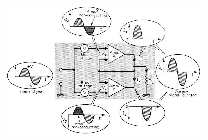
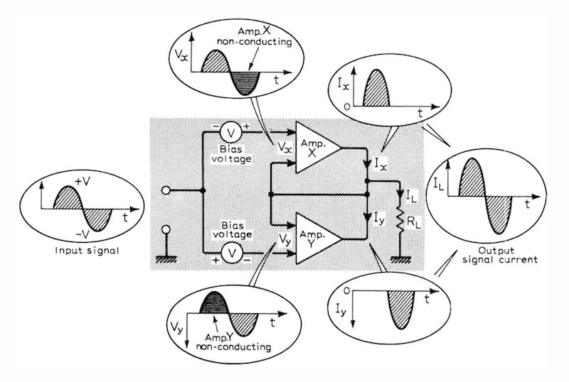
The Blomley amplifier was designed over forty years ago, is an alternative power amplifier design that suffers virtually no distortion, and provides a sound which has the presence often lacking in conventional amplifiers.
glacial spruce
It's a kind of sloppy class B push-pull.
karmic siren
Thanks for the link, @dull basalt. I'm more used to seeing push-pull done as below, where there are diodes or some other device to prevent a "crossover notch" where neither output transistor is conducting when the signal is near zero volts.
The Blomley design seems to do some fancy stuff with diodes and a current source to make the push and pull sides switch on and off at just the right time. ("Difficult-to-understand circuitry," as that article puts it.) I don't see such subtlety in the circuit I asked about.
glacial spruce
It minimizes the crossover notch, but hardly prevents it. This is one reason why push-pull amplifiers can have rough sound for low-level signals.
dull basalt
I'm making a project that uses the vs1053 adafruit shield to play music for a spinning christmas tree I made. I have LEDS attached to the tree, but I want them to interact with the music. For example, the lower tier of lights would pulse every time the bass is hit on a drum set in a song, and the upper tier would blink everytime the hi-hat is played. How would I got about doing this? In my head it seems simple but I don't know how to code it. Any help would be appreciated.
Here's a link to a resource for vs1053 Class Reference https://mpflaga.github.io/Arduino_Library-vs1053_for_SdFat/classvs1053.html
marsh pendant
heya! I'm reading through the first sample of code for sampling audio from a microphone on this adafruit post: https://learn.adafruit.com/adafruit-microphone-amplifier-breakout/measuring-sound-levels
I get all of the stuff that's happening except for the last step of converting the signal to volts:
double volts = (peakToPeak * 5.0) / 1024; // convert to volts
Is the idea that in code we're measuring one volt as one kilobyte (1024), and we know the signal we get is less than a volt so we amplify it by 5 times and then divide that by the number of volts?

Adafruit Learning System
Measure Sound Levels with the Adafruit Microphone Amplifier
blergh, typing that out I don't know if that assumption makes sense
I get that we're converting the analog signal into volts, I just want to understand the reasoning behind the equation for my own edification
 wanton grotto
The ADC is ten bits. It reads the voltage as a value from 0-1023
If the voltage range represents 0-5V, then to convert the ADC value into volts you need to multiply it by 5 and divide by 1024
marsh pendant
sorry, I had to hop into a meeting so all I could say was thanks.
To restate so that I make sure I understand what you explained and what I've been reading separately:
When the microcontroller Converts from Analog to Digital (ADC), the voltage change is represented in a value between 0 to 1023 (10 bits == 2^10 == 1024).
To make this value useful we want to think of that it in the context of our full voltage range that our microcontroller can handle which is 0 to 5v, so we multiply the signal by 5 and divide it by 1024 to map the signal to our total voltage range.
right?
(sorry for being so verbose, just want to make sure I'm getting it)
glacial spruce
Yes, that's right.
marsh pendant
ok cool. thanks 🙇♂️
marsh pendant
Aw yeah! I added the audio detection into my prototype and now I have a mic triggered dancing flower prototype 😄 https://vimeo.com/375476532
twin hawk
Does someone know why my pam8302 amplifier makes big noise about 1 second after connecting the usb? I disconnect power and ground and it still makes noise.
glacial spruce
Hmm, the PAM8302 doesn't support USB, so I think I'm missing something
twin hawk
Connecting usb, i mean that i power up my esp32.
glacial spruce
Hmm, could be interference from the ESP32 antenna, or noise on the signal or power supply leads.
To test for a signal problem, disconnect your audio source and just connect A+ and A- together (and perhaps to ground as well). If the noise still persists, it's not on the signal lines.
If it's not on the signal lines it could be conducted interference on the power supply leads, try adding some decoupling (like a capacitor) to the power supply leads. It could also be radiated interference from the ESP32 WiFi antenna, try moving them farther apart or putting a grounded conductive shield between them.
If it is on the signal lines, it's a trickier problem: you need to somehow keep the interference from coupling in on those leads, you could try a shielded cord, twisted pair, some shunt impedance, etc.
 rotund grove
@dull basalt There are some clever ideas in this forum discussion:
https://forums.adafruit.com/viewtopic.php?f=22&t=80921&p=454003
 hexed hull
I have summed a stereo cable to mono and then on to the 3.5mm line in, but none of my devices (iphone, windows laptop) like recognize that I have connected it when I try to test it out. Do I need to do something with the L/R connections on the 3.5mm, to trick em to thinking I have connected an headset?
or did I mess something up with my soldering? 🙈
glacial spruce
Are you using a TRS or TRRS plug?
hexed hull
TRRS, 3 = ground, 4 = mic, counted from the tip
glacial spruce
Yeah, that matches the CTIA wiring, which ought to be correct. You could try connecting the mic sleeve to something (maybe just ground it).
hexed hull
You mean just mic to ground and see if the device pick it up? That didn't do anything unfortunately
glacial spruce
I figured it was worth a try, some devices see that as if it were a TRS jack and act accordingly. It could be they're looking for a different electrical signature. You could try adding series resistors or somesuch. Do you have something they do recognize that you could measure?
hexed hull
Thanks for helping @glacial spruce I have an regular trrs headset, can I measure the rings without cutting it apart?
glacial spruce
Yeah, you can measure it with a multimeter
hexed hull
The mic-ground impedance (correct term? measured the ohm) was different so I matched my cable to the headsets, but still no response from the iphone
 warm rivet
Hi i am using the stereo amplifier (https://www.adafruit.com/product/987) with 8ohm 1 amp speakers (https://www.adafruit.com/product/3923) When it gets loud the speakers are popping (not sure if its a circuit issue or something). Also when no sound is played, (and power is connected) there is a constant white noise on the speakers. I'm not sure if i connected something wrongly thanks!
 icy atlas
I read that audioio library do not work with Gemma M0. Is there another way to play WAV files with Gemma M0?
 scenic axle
@icy atlas I'm not extremely familiar with all the circuitpython libraries and compatibility, but this should work as a hardware solution: https://www.adafruit.com/product/1381
This breakout board is the ultimate companion for the VLSI VS1053B DSP codec chip. The VS1053 can decode a wide variety of audio formats such as MP3, AAC, Ogg Vorbis, WMA, MIDI, FLAC, WAV ...
@warm rivet What DAC are you using? In my experience with audio gear, that sort of thing can often be caused by a bad DAC or a DAC not suited well for your use case
warm rivet
i dont have a dac, I think its probably because im just doing testing righ tnow and my headphone wires are exposed and connected through a breadboard
i just used a 3.5 mil headphone pin and connected it from my pi to the headphone jack
icy atlas
@scenic axle Thank you for your replay. Actually I was hoping to use the Gemma M0 analog output without any external hardware. On the Gemma M0 specs page Adafruit states that it can play 10-bit quality audio clips
scenic axle
@warm rivet Wait, you're hearing the hissing and popping through the 8ohm 1A speakers or your headphones?
@icy atlas I'm not familiar enough with the gemma M0 board to find a way around this without using any external hardware
warm rivet
the speakers
scenic axle
@warm rivet Ah, the dac on the pi isn't great, but it shouldn't be causing that sort of noise. Just for kicks, try covering everything except for the pi in tin foil and see if that does anything. If that doesn't help, then I'd bet it's the dac in the pi as what you're describing is pretty consistent with what happens when you need a better dac
warm rivet
is there a way to get the audio through the gpio? or does the dac connect through the 3.5 mil? @scenic axle
warm rivet
well it has white noise without being connected to anything
so im assuming is because of how my wires are exposed and not very officially connected thats causing these problems/
warm rivet
ok ive figured out the main issue is the L- and R- to ground
once i remove that its silent
is that supposed to happen? What do i ground it to (right now its connected on breadboard to the groudn for the headphone jack)
glacial spruce
Yes, that's how it works: the audio input is interpreted as the difference between the + and - inputs. If the - inputs aren't connected, they just pick up noise, and the difference between that and the connected input (noise + signal) is interpreted as the signal.
weary sentinel
@glacial spruce Thank you, serendipitously! I've never done anything with audio, but my speaker, amp, and sound breakout boards are out for delivery now. <new adventure in electronics>
glacial spruce
Woot! That's exciting!
weary sentinel
My searching is coming up empty (perhaps I'm too tired still). I could swear I saw an article in the learning system about how to configure two i2s devices on a Raspberry Pi. Or how to daisychain two together. I have an SPH0645 microphone and a MAX 9835 amp. I want to (rather obviously) listen on the mic and produce sounds on the speaker. Speaker is working but the mic is not. Any ideas or links to instructions?
dull basalt
i2c is a parallel bus with different addresses per device. As long as there's no address collision, you should be good.
master-transmitter master-receiver slave-transmitter and slave receiver (or something along those lines) are the four roles that devices play on the i2c bus.
@weary sentinel so it's just the two pins on the Pi.
You would review the datasheet for the devices you've put on the i2c bus, to determine their addresses.
weary sentinel
The devices are i2s...
dull basalt
Probably a sniffer program to determine them without a manual/reference; but I don't know how that's done.
Oh i2s haha.
weary sentinel
🙂
dull basalt
I was under the impression i2s was named that because it was 'so similar' to i2c.
weary sentinel
I would love it if this were i2c-like. But there's Select, LRCL, Din, Dout, Bclk, which seems quite a bit different than SDA and SCL.
dull basalt
I can see that now. :)
https://en.wikipedia.org/wiki/I²S
weary sentinel
I've been spending all my time in the Learning System. Maybe I should branch out to other tech sites.
weary sentinel
But later. I have CircuitPython libraries to write....
shadow aurora
I think something mentions i2s being named in the spirit of i2c as a simple, generic, communication between chips. Not in their workings, but the style of the design. I'm sure I read that somewhere.
It looks like the Pis have i2s in and out, but they share clock lines, so you'll have to run them at the same clock rate and stereo/mono
 charred trail
hey gang, having some trouble with audio out on a Circuit Playground express, anyone good with that?
glacial spruce
@charred trail I've used the DAC audio output on different boards that use the same chip?
charred trail
@glacial spruce the issue I'm having may be tied to the actual CPB hardware but I'm trying to understand what dictates use of the built in speaker or the Audio out pin, it seems to use either at random with no change in code
glacial spruce
Oh, do you mean a Circuit Playground Express (Atmel M0 CPU) or Circuit Playground Bluefruit (Nordic CPU)?
charred trail
@ @glacial spruce it is a Circuit Playground Bluefruit
glacial spruce
Ah, I'm not familiar with that one.
 echo hedge
@charred trail there is a speaker enable pin D11 that will turn on the amp to the speaker. the audio should always be on the pin itself
charred trail
@echo hedge so why would it randomly play through the built in speaker, and then sometimes the audio out pin,,,would it default to the speaker if a load was not on the audio out pin?
 thorny pelican
I just finished following this: https://learn.adafruit.com/3d-printed-amp-box/circuit-diagram and it works well at lower volumes but if i turn it up too much, the sound starts to get choppy, dropping out for little bits. any ideas what could be wrong or how to fix this issue? Thanks, Joshua

Adafruit Learning System
Build an audio project that pumps 20 watts of power with the MAX9744 stereo amplifier.
if you have any ideas, feel free to DM me
glacial spruce
@thorny pelican My first guess would be power supply limitations.
 lament latch
hello here. I have a problem with a monster m4sk and audio with circuit python.
the diag tool works well : if I shake the board, It make a sound.
but when I create a audioio.AudioOut object with circuit python, it output a weird sound even if I don't use the .play() method. after that, the real sound I want is never played
tested with 2 wav files, and the sine wave method.
it's the same if I use the jack instead of the little speaker
it's the same if I plug a battery or if I plug the USB cable in my PC
with the jack plugged in, pin A0 and A1 for the left and right channel, there is first a quick sound (high tone to low tone) like with the speaker, for the left channel, and another sound, around 13-14 sec after, high tone to low tone, but stretched to last 2+ seconds, on the right channel.
I tough it could be material, but the M4SK_Diagnostic.UF2 play sound perfectly...
the question now is : How can I troubleshoot further myself ?
glacial spruce
You may want to ask that in #help-with-circuitpython
glacial spruce
Not offhand, but maybe the authors of the page do.
dull basalt
I want to make a program that will work with MIDI in Java
I want to step through the MIDI file's ticks and read each note it plays, and do a certain action for each note specifically
But I'm having a hard time finding where to start understanding MIDI's internals
To water down the summary of what I'm doing, I'm making a sort of visualizer
So, how would this work? Would I step through the MIDI track, and for each step, see what notes get played, iterate through those notes, and activate the corresponding note in the visualizer for each note, every tick?
glacial spruce
I tend to think of MIDI as a serial protocol, I'm not sure how it's stored in files.
glacial spruce
Asynchronous serial data. That's how I send performance data to/from my keyboards/synths and computers.
Simple commands like "note on" and "note off", of course there are many more, but it sounds like those would be all you'd need.
dull basalt
Yes
karmic siren
MIDI File Format Spec. 1.1+
As @glacial spruce says, MIDI is mainly "note on" and "note off" events with a key number and a "velocity", along with non-note control information. The serial MIDI protocol has no notion of time. Note events arrive whenever they arrive. Time only comes into the picture when you store a sequence of MIDI events in the file and want to play them back as they were played.
karmic siren
And the idea of a step is something that belongs to the sequencer software. It isn't part of the MIDI file. The software decides how big a delta time each step takes and figures out which notes belong to each step.
dull basalt
I'm just reading an already acquired file here, not recording
Or live-processing
I have the file. I made a sequencer object in Java. Now, is a sequencer some sort of iterative object, usually?
var sequencer = MidiSystem.getSequencer();

if (sequencer == null) {
    System.err.println("[ERROR]: Sequencer device not supported");
    return;
}

sequencer.open();

var sequence = MidiSystem.getSequence(new File("Ye04.mid"));
sequencer.setSequence(sequence);
I always start with a program that reads the file and prints the data back out with some formatting. That way I can see what's in the file and if I'm interpreting it in a way that it makes sense.
dull basalt
Does a MIDI file have a sense of time? Or is it just an arrangement of instructions for the software to put space between?
That's sort of what I'm getting right now
karmic siren
Yes, the MIDI file does have time information in it.
dull basalt
I see
karmic siren
How hard would it be to write a little program that read bytes from the file and just decoded the "Header chunk" at the beginning, as described in that Standard MIDI File Format document?
glacial spruce
It may well be easier than using the heavyweight "Sequencer" object. On the other hand the sequencer probably takes care of the timing for you.
karmic siren
Yes, depending on what functionality that object exports.
Some years ago I wrote all this in VBA to put all the event information in the file into an Excel spreadsheet. It took like an hour or something.
The spec looks intimidating but it isn't as hard as it looks. Go down from the top, from chunks to tracks to events.
dull basalt
@tardy jetty and anyone else who might have input on this. TrellisM4 Expressive USB MIDI Controller is fun. The goal is to use onboard audio jack instead of computer audio jack/port so the cord can be extension and portable. Adding "AudioOutputAnalogStereo audioOutput;" in the code is not working. Is there enabled or need to re write some code to do that? I kept getting confused on input/output. USB is output from computer to NeoTrellis M4 board then audio jack is output to use a headphone, is that correct ? I also had attempted using PJRC Synth Tool to get some writing code for USB to DACS1, the result is 'AudioInputUSB" is not recognized" My best assume is to set STEMMA port to add second audio jack to receive directly from MIDI usb instead of computer audio jack. I think it might be work which is similar to trellis_audio_fft. Shall see what will happen.
dull basalt
wow... everyone is so quiet... Am I in wrong direction for asking some help with audio? Or should I be in "help-with-projects"?
glacial spruce
You're in the right place, but some people aren't around all the time, and your question is addressed to one particular person, and hinges on fairly specific details that not a lot of people might know enough about to offer something useful.
dull basalt
@glacial spruce Ah, I understand. I apologize if I address to one particular person because he created the code for Expressive MIDI Controller. But I should put down @ person + @ everyone 🙂
glacial spruce
Not @ everyone (that's not helpful), but perhaps something like @ someone "and anyone else who might have input on this"
 tardy jetty
@dull basalt if I understand correctly, you want to make a synthesizer with the Trellis M4 that has audio output from the Trellis M4 headphone jack. This guide shows how to do that: https://learn.adafruit.com/synthesizer-design-tool/overview Are you also trying to send audio from your computer to the Trellis M4 over USB? I don't think that is possible.
 neon portal
I've bought a speaker that says 8ohm 0.1W on the back. Does this mean I should supply it 0.1W?
glacial spruce
That means it can withstand up to 0.1W
dull basalt
@tardy jetty and anyone else who might have input on this. I did have used Synthesizer Design Tool by using USB as input and dacs as output. I found some article audio over usb (http://openaudio.blogspot.com/2016/10/teensy-audio-over-usb.html) and attempted to code some alternative to match on Trellis M4. I received the error message that "AudioInputUSB is not in the scope." Since you said sending audio from computer/usb to the Trellis M4 is not possible, that might be why it is not working. Eh? It is never hurt to experiment. 🙂
tardy jetty
@dull basalt I'd like to look into this a bit more -- it may be a hardware difference between Teensy and Trellis M4, or it could be just something that wasn't ported when we forked the Teensy Audio code.
dull basalt
@tardy jetty Ah, cool. I just like to use my headphone on Trellis m4 instead of computer audio jack to avoid awkward short headphone cord connected to computer and being closer to computer screen.
I would like to post this to share about Sugarcube MIDI controller (it might be outdated but grateful for her hard workings) that will be beautiful on Trellis M4. Especially Trellis M4 is ready-made instead of so much bunch wirings and codings like Sugarcube MIDI Controller did. https://www.instructables.com/id/Sugarcube-MIDI-Controller/

Instructables
Sugarcube MIDI Controller: This project is a portable, Arduino-powered, grid-based MIDI controller that boots up into a variety of apps to do lots of things with sound. It has 16 backlit buttons, used as both inputs and outputs to give the controller some visual feedback....
tardy jetty
nice!
dull basalt
@dull basalt If you make a custom mask you can remove some of those buttons to give it less of a 4x4 feel to it.
(and go 8x4 with NeoTrellis M4) (less a few buttons, here and there, for that custom look)
 daring birch
I am considering switching to a different audio Bluetooth modules. (I am using WT32i.) Suggestions? Especially, is there something AdaFruit has that I can use?
 paper wren
On the NeoTrellis M4, is it possible to output audio tones to left and right track (board.A0, and board.A1) at the same time? I tried using AudioOut but I get an error when I try to initialize the second pin.
 solemn flint
The chip does have dual DACs, so it should be capable of it, but I can't comment on the driver code support.
paper wren
Ah, I got it. The constructor can take left_channel and right_channel args
it plays to both at once, although it'd also be cool to play out different things out of them at same time
glacial spruce
I assume it can be done with Arduino (I've done it with the ItsyBitsy M4), but I don't know if CircuitPython supports it.
paper wren
Poking around a bit more in the audioio package this morning I found the Mixer class that might help us achieve it with Circuit Python. I am a bit new to the audio world though I don't think I understand fully what it is capable of. Is there anywhere that gives a good high level introduction to the concepts and vocab? In particular I'm not sure I am understanding what are "voices" and what are "channels"
paper wren
This sample project: https://learn.adafruit.com/trellis-m4-beat-sequencer/eight-step-simple-sequencer does a pretty good job. I have a better understanding of AudioOut and Mixer after looking through this code.
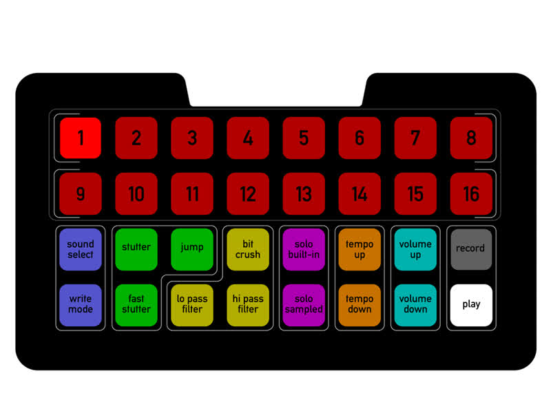
Adafruit Learning System
Drum machine time! Play the drums with both a simple and a more complex set of sequencers.
daring birch
@paper wren Something to try: To get two independent audio outputs, create two, each with only a left channel. I don't know if this really works.
paper wren
Well, I get a "DAC already in use" or something similar error if I try to init a second AudioOut
dull basalt
@dull basalt yes- like an example of 8 x 8 Neotrellis Feather M4 kit that has a power switch and use the feather board to configure potentiometers. For 8 x 4 M4 Express board might be work
by using STEMMA port to add some potentiometers. I don't know, I will experiment and see what will be result.
Tellis M4 Beat Sequencers is fun to play. Sometimes if use connect to USB to computer act strange or no noise at all. It is better to plug direct to battery bank or wall outlet. I believe the computer with usb interfere.
daring birch
@paper wren Ah, sorry, I thought I was being clever. Uh, did you use a different pin for the second?
paper wren
Yep, I tried A0 and A1 I did find that I was able to switch back and forth pretty rapidly by using deinit() in between using each one. which made for a neat effect for a bit
 craggy depot
Can anyone help me. I'm about to do a music project with my students. What are the nicest speakers to use with the Crickit?
glacial spruce
Depends on what's important to you. These sound pretty good, since they're already enclosed, but you could get even better sound with other speakers if you built a custom enclosure for them. https://www.adafruit.com/product/1669
Listen up! This set of two 2.8" x 1.2" speakers are the perfect addition to any audio project where you need 4 ohm impedance and 3W or less of power. We particularly like these ...
 steady ruin
Hi all, does anyone know if the VS1053 music maker featherwing supports midi playback in circuitpython? I am attaching it to my pybadge for my ongoing step sequencer in the style of LSDJ/nanoloop. I have the outline for code in cpp and python to control the screen and tempo, so if no python support I will continue using arduino.
fickle leaf
@steady ruin Yes, I've used it as a MIDI voice module with a Feather and as a standalone MIDI device. If I recall, a solder jumper needs to be installed on the bottom of the board. MIDI input is sent to the TX pin. You can communicate directly via the UART or adafruit_midi CircuitPython library.
steady ruin
@fickle leaf Thanks! After looking through the data sheet, I see that in midi mode it's just standard midi in on the pin, so it seems I only need the midi library to interface with the featherwing.
steady ruin
The big benefit with doing it in circuitpython is the ease of saving and transferring song data. Who knows, I may even be able to add support for importing deflemask .DMF song data
grand lance
i need some advice. i need a good chip (smd) to ad sound to a project
glacial spruce
What sort of sound chip? A sound synthesis chip, or a programmable oscillator, or a DAC?
grand lance
music and sound effects
glacial spruce
You can attack that a few ways. You can just use a DAC and have the CPU feed it digital audio. You can use something like an FM synthesis chip and have the CPU tell it what you want to hear and it'll create the waveforms for you. Or you can use canned samples and a playback chip, then the CPU just tells it which ones to play and when.
grand lance
so a constant hum would be a canned sample that gets replayed over and over until another cound takes over, like the laugh tracks on tv shows
glacial spruce
Yup.
 iron cliff
I had my kiddo sign up for an audio science project. If we capture the audio delay using an arduino, we could compute the speed of sound experimentally. After looking at a little bit we realized, that it's too trivial of a project because you can just use an ultrasonic sensor and just count the microseconds between trigger and echo event. -- Now we're considering implementing this without the ultrasonic sensor. If we decide to implement this with a speaker and microphone (with speaker one end of table and microphone on the other) where the speaker outputs a quick high frequency chirp, what type of interfacing circuitry would be required on the microphone side if we just want to get a quick interrupt for the arduino.
solemn flint
The simplest would be a comparator and potentiometer, where you could tune the threshold level to detect the peak of the chirp.
Actually it looks like some Arduino CPUs have a built-in analog comparator feature, so that's potentially even easier. I'm not sure if it's supported by library code, though.
iron cliff
I think the comparator might be the best option for this. Thanks
 potent olive
hi everyone, I'm trying to play audio stored in an sd card using an NRF52840 feather express board.
Do you guys know what is the best approach for this?
glacial spruce
It depends on how it's stored.
potent olive
thanks for getting back to me. I stored it in the sd card as a .WAV.
do you guys know if the ADC con work as a DAC ?
solemn flint
Generally a peripheral is one or the other, though some microcontrollers have both (usually on different pins).
glacial spruce
Hmm, I don't know the "best" approach, but I'd probably try a layered solution. Have an SD card driver to talk to the SD card, then a filesystem driver that uses it to understand the structure of the data on the SD card, then code that can understand the WAV format, then something to take that data and send it out to a DAC at the proper rate.
Happily, code for all of these is probably fairly easy to find.
 lofty peak
any recommended PDM microphone part from adafruit
solemn flint
Not a lot of choice there... I only see one: https://www.adafruit.com/product/3492

An exotic new microphone has arrived in the Adafruit shop, a PDM MEMS Microphone! PDM is the 'third' kind of microphone you can integrate with electronics, apart from analog or I2S. ...
potent olive
Happily, code for all of these is probably fairly easy to find.
@glacial spruce thanks mate
 unreal lava
👋
i got the teensy 4.0 and the audio shield
beep and all works
but i cant access the sd card
is there some special setup needed or is my sd card maybe not suited ?
glacial spruce
How are you trying to access the SD card? What happens when you try to access it?
unreal lava
there is a library example of teensy audio
// Advanced Microcontroller-based Audio Workshop
//
// http://www.pjrc.com/store/audio_tutorial_kit.html
// https://hackaday.io/project/8292-microcontroller-audio-workshop-had-supercon-2015
//
// Part 1-3: First "Hello World" program, play a music file
//
// WAV files for this and other Tutorials are here:
// http://www.pjrc.com/teensy/td_libs_AudioDataFiles.html

#include <Audio.h>
#include <Wire.h>
#include <SPI.h>
#include <SD.h>
#include <SerialFlash.h>

AudioPlaySdWav           playSdWav1;
AudioOutputI2S           i2s1;
AudioConnection          patchCord1(playSdWav1, 0, i2s1, 0);
AudioConnection          patchCord2(playSdWav1, 1, i2s1, 1);
AudioControlSGTL5000     sgtl5000_1;

// Use these with the Teensy Audio Shield
#define SDCARD_CS_PIN    10
#define SDCARD_MOSI_PIN  7
#define SDCARD_SCK_PIN   14

// Use these with the Teensy 3.5 & 3.6 SD card
//#define SDCARD_CS_PIN    BUILTIN_SDCARD
//#define SDCARD_MOSI_PIN  11  // not actually used
//#define SDCARD_SCK_PIN   13  // not actually used

// Use these for the SD+Wiz820 or other adaptors
//#define SDCARD_CS_PIN    4
//#define SDCARD_MOSI_PIN  11
//#define SDCARD_SCK_PIN   13


void setup() {
  Serial.begin(9600);
  AudioMemory(8);
  sgtl5000_1.enable();
  sgtl5000_1.volume(0.5);
  SPI.setMOSI(SDCARD_MOSI_PIN);
  SPI.setSCK(SDCARD_SCK_PIN);
  if (!(SD.begin(SDCARD_CS_PIN))) {
    while (1) {
      Serial.println("Unable to access the SD card");
      delay(500);
    }
  }
  delay(1000);
}

void loop() {
  if (playSdWav1.isPlaying() == false) {
    Serial.println("Start playing");
    playSdWav1.play("SDTEST2.WAV");
    delay(10); // wait for library to parse WAV info
  }
  // do nothing while playing...
}
it always jumps into the "unable to access" catch
glacial spruce
Do you know if it's a Rev C or Rev D audio shield?
glacial spruce
Yeah, I think so
unreal lava
yes
glacial spruce
Try commenting out the others and adding these ```c
// Use these with the Teensy Audio Shield for Teensy 4
#define SDCARD_CS_PIN 11
#define SDCARD_MOSI_PIN 10
#define SDCARD_SCK_PIN 13
oof
// Use these with the Teensy Audio Shield
#define SDCARD_CS_PIN    10
#define SDCARD_MOSI_PIN  11
#define SDCARD_SCK_PIN   13
that should be correct according to the diagram
left is rev d
still not working with neither 😦
glacial spruce
Heh, have another one from the chart in the docs: CS 10, MOSI 11, SCK 13 🙂
unreal lava
thats what i have up there
glacial spruce
Ah, right
unreal lava
The Arduino SD library supports up to 32 GB size. Do not use 64 & 128 GB cards.
guess what size mine is
darn
glacial spruce
Yes, the too-small (like 32MB) and too large (>32GB) don't work without a different protocol.
 raven snow
I’m debating on adding sound to my project. I’ve been looking at using a piezo because it’s louder. Which led me down the rabbit hole to this https://www.diodes.com/assets/Datasheets/PAM8904E.pdf
I’ve looked at PDM https://en.m.wikipedia.org/wiki/Pulse-density_modulation
But I’m not sure if that will let me reproduce voice in any intelligible way
Pulse-density modulation, or PDM, is a form of modulation used to represent an analog signal with a binary signal. In a PDM signal, specific amplitude values are not encoded into codewords of pulses of different weight as they would be in pulse-code modulation (PCM); rather, ...
I believe I could use SPI as the source for the signal or DMA with a GPIO. But I’m not sure how well that would work compared to DMA with a DAC but that would most likely require and regular Class D amplifier and a 4ohm speaker.
Has anyone worked with a piezo to generate distinguishable voice?
solemn flint
PDM isn't a limiting factor, as a lot of standard microphones and other audio chips use it. But piezo speakers tend to not have good sound reproduction, particularly at the low-frequency end, so they tend to be more for beeps than for voice.
raven snow
I’m not too concerned with PDM either more of how a piezo responds to the oversampling. I mean this isn’t for an audiophile. It just needs to be understandable.
unreal lava
anyone here super familiar with the audio library for teensy?
dull basalt
There was a program that ran under MS-DOS that modulated the onboard PC piezo buzzer. I bought my first PC around 1987 so that'd be the rough time frame for this ± 7 years. ;)
I seem to remember effort was made to make it sound like human speech, just a little.
Morse code annunciation is far more readable from a PC speaker.
glacial spruce
I've used the Teensy audio library, but I'm not "super familiar" with it.
unreal lava
thing is i have 16 audio channels. I made a struct for each channel containing L/R audio and L/R mixers. Since there is only a 4CH mixer i need to make 2 mixers each for each channel and 4 mixers to combine them to one master channel.
somewhere in the chain the the signal gets lost, i tried it in a super simple sketch, but it doesn't with the structs anymore
and i'm not sure if its my problem or the libraries
 tribal jay
im trying to use a teensy and an adafruit Electret Microphone to make sort of a spectrum analyzer on a ws2812b 8x32 matrix. im noticing some weird noise on the output of the microphone i cant pin point. is a weird 34hz signal thats constant. now this wouldnt be a problem but the signal is really loud, basically the maximum it can be from this mic around 1v p-p. it has to be something with the teensy since ive removed the leds from the circuit and when i remove the microphone and power it up on a seperate breadboard the output is nice and clean. I do have pictures of the signal on my osciliscope and will post those on request.
I have noticed that it has some sort of relation to my sampling rate on the teensy, at 5khz the noise ends up around 17hz, at 20khz the noise is 34khz. im not sure how to fix this and this is my first real project working with and processing audio signals, any advice would be greatly appreciated
iron cliff
Could it be an FFT artifact? Is there anyway you can filter out the high frequency component? I'm just speculating here
tribal jay
actually just fixed it. it was noise on the powerpin for the teensy, powered the microphone from the other 3.3v pin on the teensy and it worked perfectly with no noise
iron cliff
follow up to my measuring the speed of sound project.. We're deciding to measure the speed of sound through solid mediums by using this large piezo transducer: https://www.adafruit.com/product/1784
and a few piezo pick ups on a 1M solid rod.
We didn't realize how fast sound travels through metals. For example for steel it's 6420 m/s. this means the delay will only ~150 microseconds. An arduino won't be fast enough at 16 MHz clock will it?

Turn any surface/wall/table etc into a speaker with a surface transducer. This type of speaker does not have a moving cone like most speakers you've seen. Instead, a metal rod is wrapped ...
any ideas on how to measure this delay either digitally or with analog? How about an FPGA?
dull basalt
Speed of sound is near 700 MPH depending on the weather.
312 meters per second, I think that works out to.
6420/312 = 20 times faster in steel. ;)
150 µSec / 0.0625 = 2400 clock pulses per 150 µSec.
So if it took, say, 10 clock cycles to 'do something interesting' then there are 240 such intervals available during the 150 µSec event.
Sounds like maybe a 6-bit resolution, but I'm way out of my experience range with that. ;)
(240 is close to 256 which is 8-bit resolution)
iron cliff
Ahh yeah. Thanks. I was off on my math. It should totally be possible to measure this with an Arduino
 proper owl
Hello I have a basic audio question. I'm working with my CPX and adding audio. I'm trying to do other things with the program when the audio plays so I'm not using the cpx.play_file("wavefile") command. I have looked at the learn guides at am using the following code to play a file while I have the
Sorry- this is the rest of last message
this is the code I'm using:wave_file = open("02.wav", "rb")
wave = audioio.WaveFile(wave_file)
audio = audioio.AudioOut(board.A0)
When I use this code I can only use the external speaker if I have imported the cpx library. I have modified the program to so that I enable the speaker using the following code:spkrenable = digitalio.DigitalInOut(board.SPEAKER_ENABLE)
spkrenable.direction = digitalio.Direction.OUTPUT
spkrenable.value = True
What I'm wondering is: Can I use all of the easy cpx. commands while I have the board not stop all that it is doing to play a file while using the speaker on the CPX or is this only possible while using an external speaker.
glacial spruce
I'm guessing it's possible, but I'm not sure. You might try asking in the #help-with-circuitpython channel
dull basalt
afaik the MCU isn't aware of an internal vs external speaker 'state' of any sort.
What it has, instead, is SWCLK/SPK_SD on PA_30 to enable or disable the amplifier driving the external speaker.
@proper owl You can delimit code with three backticks:
```
on a line by itself, twice (at the beginning, and end of your code).
proper owl
thank you for the help. I'll ask at help-with-circuitpython
I'm not understanding what code I would delimit? Please explain. Thank you
dull basalt
@proper owl You can just @dull basalt (Or whom ever) to let them know you replied to them. It's not always necessary to do so.
You cited some code you'd written, above; setting it off in backticks makes it a whole lot more legible, here.
wave_file = open("02.wav", "rb")
wave = audioio.WaveFile(wave_file)
audio = audioio.AudioOut(board.A0)
# When I use this code I can only use the external speaker
# if I have imported the cpx library.
# I have modified the program to so that I
# enable the speaker using the following code:
spkrenable = digitalio.DigitalInOut(board.SPEAKER_ENABLE)
spkrenable.direction = digitalio.Direction.OUTPUT
spkrenable.value = True
I added python so the syntax highlighting would be python-specific:
```python
code
```
 sullen portal
Hi all, I am quite new to physical computing. I am working on a project where I would like to connect both an RFID reader and an audio card to a Raspberry Pi. I've bought the Adafruit Speaker Bonnet but I first didn't realise that it would cover all the GPIO pins. After some google searches, it looks possible to connect the Bonnet without mounting it. I found this pinout: https://pinout.xyz/pinout/speaker_bonnet My question is, do I also need to connect to a Ground? Or just to the pins specified in the pinout above? Sorry if it is a very obvious thing but this is only my second RasPi project all in all. Thank you in advance ☺️

3W Stereo Amplifier Bonnet for Raspberry Pi
glacial spruce
Yes, the ground is also required. Some bonnets can be assembled with "stacking" headers so that more than one can be plugged directly in, as long as they don't have conflicts in the pins they need.
sullen portal
Perfect! Thank you for the quick help!
 opaque jay
Does anyone know the pinout for this jack?
https://www.adafruit.com/product/1699

Pipe audio in or out of your project with this very handy breadboard-friendly audio jack. It's a stereo jack with disconnect-switches on Left and Right channels as well as a center ...
sullen portal
Hi again, so I've installed the speaker bonnet, followed the guide on the Adafruit page, then did the demos. I've got sound just fine with all of the test material but it seams I cannot get sound when I try to play anything else (my own files, for example), neither wav files nor mp3. (I've installed mpg123). When I open VLC and click on audio device, and try to click on speaker bonnet, it says "audio output failed: the audio device speaker bonnet could not be used: device or resource busy"
dull basalt
@opaque jay Since very inexpensive parts can be had out of a parts bin at a (ham radio oriented) flea market (so they are entirely undocumented) the usual thing to do is to "Ohm it out" (put a multimeter on the different terminals and check for continuity).
fickle leaf
@opaque jay There's a datasheet link on the page you referenced: https://cdn-shop.adafruit.com/product-files/1699/STX3120.pdf
sullen portal
Hi again, so I've installed the speaker bonnet, followed the guide on the Adafruit page, then did the demos. I've got sound just fine with all of the test material but it seams I cannot get sound when I try to play anything else (my own files, for example), neither wav files nor mp3. (I've installed mpg123). When I open VLC and click on audio device, and try to click on speaker bonnet, it says "audio output failed: the audio device speaker bonnet could not be used: device or resource busy"
@sullen portal It's working now! It seems my soldering on one side wasn't good enough.
 outer gate
I have no clue how this stuff works, but I find it really interesting. If anyone has thoughts on it let me know!

Burson V6 Vivid and V6 Classic fully discrete audio opamps
Both designs evolved from the Burson V5. But just as evolution is never linear, two V6 circuitries emerged to compete for the hearts and minds of music enthusiasts.
Designed to optimise
glacial spruce
I actually prefer integrated circuit op-amps, as thermal tracking and device matching can be quite good. For discrete op-amps, I have an especial fondness for the Philbrick K2-W, but it does eat a lot of power. Of course, it can be a useful adventure to build your own discrete op-amp, there's much to learn.
outer gate
@glacial spruce Would you happen to know how to get started? I've used a couple cheap IC chips like the 5534 and I've listened to higher end ones like the 637 Metal can version. Thanks!
glacial spruce
Happily, this is the sort of material that's covered in electronics courses, so the course notes are a great starting point. Here's one https://inst.eecs.berkeley.edu/~ee140/sp14/labs/Lab2.ee140.s14.v1.pdf
Here's a writeup that goes into more detail on sonic characteristics https://www.passdiy.com/pdf/diyopamp.pdf
There is a kit to build a 741 out of discrete components https://www.evilmadscientist.com/2014/the-xl741/ but as you know the 741 is an ancient design with fairly poor characteristics.
The 5532/4 is a pretty good chip, suitable for many circuits. There are fancier ones available like the AD823, and the very expensive OPA627 with really good specifications. If you want a design that's not from the 20th century (analog electronics doesn't seem to discard things as fast as digital electronics), there's the OPA827 introduced in 2006.
outer gate
Awesome, thanks for all the info, I'll check those links out
light crag
How do I fix this
I know this i common problem in audio stuff
I think it's a ground loop but not really sure
glacial spruce
Could be hum injection, hum coupling, ground loop, or open ground. The fixes for each of them are different.
glacial spruce
Kinda old?
light crag
Logitech s3-30 speakers
Pretty simple circuit tbh
It has 2 amps
To be honest I found it in a dumpster room without cable or speakers
But it works i don't think that hum is because broken that hum is common in many amplifier and speakers
But anyway how do I fix it
glacial spruce
First you have to figure out where it's coming from. Does it go away with the input disconnected? Is the power cord grounded?
light crag
Power cord not grouned it is extrnal brick
I would rather have internal psu tho
No hum when I disconnect the aux
glacial spruce
Okay, if it's not a grounded power supply, it's probably not a ground loop.
light crag
I think it's somewhere at the input
I don't have grounded power outlets so that would not matter anyway
glacial spruce
If there's no hum with the input disconnected, it probably isn't power supply hum either.
That leaves something about the input source, the cable, or the connection.
I think the likely place is the input connector, a solder joint may have cracked so it's not properly grounded. Might be worth putting a little contact cleaner on the plug and plugging and removing it a few times to clean the contacts, and reheat the connector pins with a soldering iron to make sure they have a good connection.
You can always hack off the connector and replace it with an RCA jack or similar and use that instead.
light crag
I would like to have rca these speakers have rca
glacial spruce
Yeah, the 1/8" connectors are a little twee, I prefer RCA too.
light crag
Ah i touch on the line in i hear hum
Now when nothing is connected its just a small his
Wish is OK
Really nothing wrong just it picks up noice a filter capacitors should fix that
glacial spruce
Sounds like you've got it fixed, yay!
light crag
No one question what capacitors do you think I should use
glacial spruce
Power supply capacitors or signal filtering capacitors?
light crag
Well filter ones
Elna caps should be good
glacial spruce
Yeah, that's a good brand. I misunderstood what you were asking anyway, I thought you were asking about reactance/value/technology but you were asking about manufacturers.
light crag
oh
but i think 2 filter caps between ground and left and righ input should fix it imma try that
glacial spruce
It might reduce hiss, but can also impact the treble response. Since it's a subwoofer, that shouldn't matter much.
light crag
I will reverse engineer it instead and remake it instead
I know how it works it separate the low and high frequencies and it goes through 2 separate amplifiers
glacial spruce
That's the usual approach, either a crossover and bi-amplification, or a single amplifier and then a speaker-level passive crossover.
light crag
How do I make a low pass filter then
I already have a amplifier... In my pc it's my sound card I am sure it can handle that at least my 2 jvc speakers but on the other side I can reuse the amplifier from the subwoofer that's what I was thinking
dull basalt
Inductors pass DC and attenuate AC.
Capacitors pass AC and block DC.
https://www.allaboutcircuits.com/textbook/alternating-current/chpt-8/low-pass-filters/

Read about Low-pass Filters (Filters) in our free Electronics Textbook
'Crossover' is a word used for audio where it concerns components close to the loudspeaker.
glacial spruce
A simple one-pole low-pass filter can be as simple as a series resistor and parallel capacitor.
proper owl
Hello All. Last week I received some nice help when I was working on an audio project that I'm using as a demonstration for a workshop that I'm leading later this month. I've attached the link for the YouTube video of my finished product. I was initially asking for help because when I use the CPX helper functions and also use CircuitPython to open and use several audio files I can't use the onboard speaker. I never did figure out a workaround but in the end I used some powered speakers for this project. Thanks for the advice offered last week!https://www.youtube.com/watch?v=WkCSLAD4SI4&t=14s
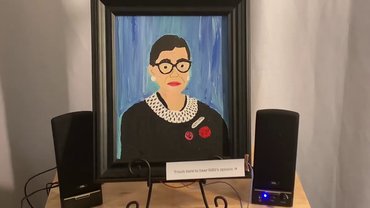
This DIY video demonstrates a STEM project which uses a circuit playground express from Adafruit and is coded using CircuitPython. A painting is created and public statements are recorded and modified to fit on the CPX. When the pad is touched the CPX is activated to start on...
unreal lava
has anyone ever saved record data to the flash memory slot on an audio shield rev d for the teensy?
the audio docs state that it will be implemented int he future, i kinda need it now tho
glacial spruce
Seems like it shouldn't be too tough, you might be able to use a generic SD card library to talk to it (it's just SPI) by setting up the pins correctly.
unreal lava
tought so to, not working tho
it can't open a connection
#define MEM_CS_PIN 6
#define MEM_MOSI_PIN 11
#define MEM_SCK_PIN 13

void setup()
{
  AudioMemory(120);
  sgtl5000.enable();
  sgtl5000.inputSelect(AUDIO_INPUT_LINEIN);
  sgtl5000.volume(1);

  SPI.setMOSI(MEM_MOSI_PIN);
  SPI.setSCK(MEM_SCK_PIN);
  if (!(SD.begin(MEM_CS_PIN)))
  {
    // stop here if no SD card, but print a message
    while (1)
    {
      Serial.println("Unable to access the SD card");
      delay(500);
    }
  }
}```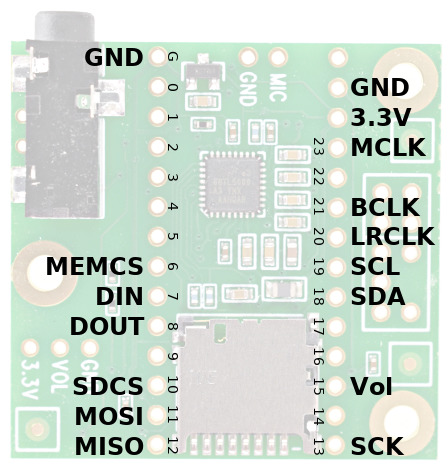
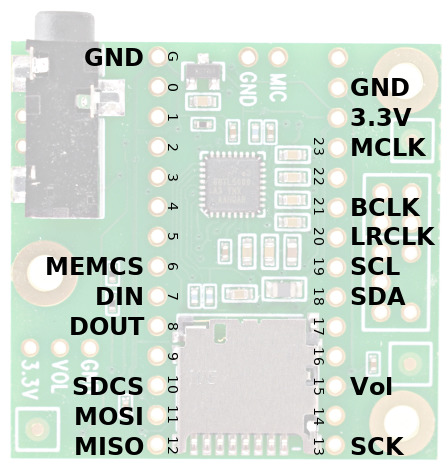 glacial spruce
You probably want to use SDCS to talk to the SD card.
glacial spruce
I misunderstood, I figured you meant the SD card.
You'd need a different driver for the flash memory chip.
unreal lava
which is?
i assume something like this

GitHub
Arduino library for Flash Memory Chips (SPI based only). Formerly SPIFlash - Marzogh/SPIMemory
 rugged trellis
I still cant find a good z80 fat32 library
glacial spruce
It seems like there ought to be a C implementation you could use.
rugged trellis
crap sorry I posted in the wrong channal
echo hedge
@proper owl awesome project!
 shrewd sequoia
Hi everyone, I would like to make my Trellis M4 cordless, does anyone have experience with a Bluetooth audio transmitter that i could connect to it's output? A small board would be ideal but a commercial unit that i can hack would do fine. Thank you.
glacial spruce
I've done a couple of things like that with IR and FM modulators, and I assume there's such a Bluetooth module in existence, but I have no experience with them.
shrewd sequoia
Well IR and FM sounds interesting, would you have some links? I sourced out a Bluetooth audio transceiver from a local supplier but it cost $40.00. First thought of a Bluetooth connection because my main stereo is connected to my computer but now thinking it out a dedicated transmitter/receiver with a line in/out would be better. Thanks for sharing the experience.
glacial spruce
I think the FM transmitter was a earlier version of a Griffin iTrip that I picked up used at a hamfest for $5. I pulled it out of its housing and just used the bare board. Worked fine. Controlling it required some reverse engineering, which revealed that it would transmit outside the FM band if asked to.
The IR project was even older (1980s?), I certainly don't have a link for it!
I had hacked up a pair of wireless infrared headphones for the unit. A quick search for "wireless infrared headphones" on eBay yields a set for $19.
shrewd sequoia
I built small FM transmitters 50 years ago, guess i can do it now. You got me thinking out of the little box i got myself into, thanks madbodger.
 lucid oracle
Has anyone had any luck with streaming audio over Bluetooth with any of Adafruit's BLE products?
BLE or other Bluetooth products.
echo hedge
BLE isn't usually used for streaming audio. Legacy Bluetooth is. (The new BLE spec did just introduce something.)
lucid oracle
Cool. I'm educating myself from other people's forum posts at the moment.
echo hedge
I think Bluetooth streaming chips are pretty common but I don't know specifics.
lucid oracle
Interesting. I guess I also need a solution that works for iOS devices, so I'm not sure how that will work going back to Bluetooth Classic. I guess I'll do some more research on how modern Bluetooth headphones and such are accomplishing this.
echo hedge
I think you want A2DP iirc
lucid oracle
I need something a little smaller. Teaching a class on building a smartwatch. I guess I can reverse engineer one of those A2DP iircs.
I took apart some of my malfunctioning Bluetooth headsets and found the CSR8635 Bluetooth modules inside.
karmic siren
@lucid oracle An eBay search for "bluetooth audio adapter" is one way to browse the small cheap solutions being offered. I bought a transmitter and receiver a few years ago for a few bucks each, mainly out of curiosity, and they did what they were supposed to. A current listing picked more or less at random: https://www.ebay.com/itm/Audio-Bluetooth5-0-Transmitter-Receiver-USB-Adapter-for-TV-PC-Car-AUX-Speaker/362795945928

eBay
Transmitter mode: Red LED light is on. Receiver mode: Wirelessly streams audio from your Bluetooth-enabled phone, tablet, or computer to your wired stereo, speakers, or headphones. Only plug item in USB port is not enough!
glacial spruce
I suppose you could search on "CSR8635" too.
lucid oracle
Oh I need an embedded solution. I'm making a smarwatch and I want to have audio streaming ability.
karmic siren
Sure, thinking of this as a physical application note.
lucid oracle
@glacial spruce I found some modules and a YouTube tutorial that seem promising.
@karmic siren what do you mean? Buying those devices and tearing them apart? I like that thought.
karmic siren
Yup, or even seeing what's out there in the first place and trying to work backward to see what silicon they use, which shows up in listings sometimes.
Not always easy to breach the packaging but if you're determined enough... 😁
lucid oracle
I like that thought. It would be nice if I can find something a little smaller than the CSR modules.
karmic siren
Might ultimately be a CSR chip inside most of those things in the end.
lucid oracle
I thought that too.
Just without the module.
It seems like the defacto cheap Bluetooth audio transmitter.
The extra confirmation would be good either way.
karmic siren
Good luck with it!! That's all I've got to offer.
lucid oracle
That's perfect. Thank you everyone! I'll be sure to swing by Show and Tell to share updates. I haven't been on in a while.
marsh pendant
heya, I'm adding tones into an esp32 feather project via the ledcWriteTone function.
I'm able to get the tones to play which is great, but ... I can't get them to stop.
Here's an example of the code I'm using as a startup tone:
    ledcSetup(speaker_channel, speaker_frequency, speaker_resolution);
    ledcAttachPin(SPEAKER, speaker_channel);

    ledcWriteNote(speaker_channel, NOTE_G, 3);
    delay(100);
    ledcWriteNote(speaker_channel, NOTE_D, 4);
    delay(100);
    ledcWriteNote(speaker_channel, NOTE_A, 3);
    delay(5000);
    ledcWrite(speaker_channel, 0);
I figured that using ledcWrite on the channel I'm using for the speaker and giving it a duty cycle of 0 would stop it, but apparently it doesn't.
I'm digging through the source code but I'm not seeing a way of turning it off. Does anyone know how to do it?
Looking a the public functions in the header file I don't see any equivalent to noTone
weird, and looking at the tone function it looks like they use a 0 duty cycle to turn it off. hmm ...
🤦♂️
nevermind
the ledcWrite(speaker_channel, 0); does work, I was just being impatient and forgot that it's going to run for 5 seconds
I was literally unplugging the usb cable to cut power before giving the delay time to stop (the speaker isn't muffled yet so I was avoiding the loud sound)
nothing like facepalming in public! 🙃
 brittle geyser
I have a razer blackshark headset with a bad cable. Instead of trying to salvage the little pcb, I was thinking of rebuilding. Are there any good references for audio circuits/electronics? I have had trouble finding reference material for a beginner. (have photos of the pcb if interested)
glacial spruce
The headset itself is probably pretty simple (microphone and two speakers). Might be a mute switch as well. Is it a USB headset?
brittle geyser
Nope, stereo with a detachable mic. No mute or anything. I was surprised to find anything inside!
glacial spruce
Hmm, looks like the board is just a splitter and connector holder. The signals seem to go straight through so it should be easy enough to repair/replace.
brittle geyser
Wasn't sure about the components on the mic trace. (I'm very much a beginner)
glacial spruce
I'm not entirely clear on what they are or do either. Looks like 2 resistors and a capacitor to ground but I don't know their purpose. I doubt they're critical, but I'm not sure.
brittle geyser
I think they are important. But I realized that the connection I got to replace with was stereo only anyway. Rewired today and printed a mic port cap.
 pliant aurora
Hi ! For my project (basically, i try to translate infrared sources into spatial sound), i need polyphonic and, at least, stereo sound... Despite my days of research, i didn't found anything about this, knowing that i work on an Arduino Micro. Do you have any clue ? 🙂 Thanks in advance !
glacial spruce
Depends on what kind of stereo sound you want. If it's just beeps, a Micro could be able to do it. If you're looking for any fidelity, you'll need something like a Wave shield.
pliant aurora
Thank you ! Since the sound will be very important in my project, i need good audio, or at least not just beeps... And according to the FAQ section of the WaveShield, it can't do stereo nor polyphonic sounds :/
solemn flint
Maybe the Music Maker shield, then.
pliant aurora
Yup, i'm actually looking at it ! I'm looking for if it can do polyphonic 🙂
 final yoke
any recommended i2s (i2c) dac ic? for quality sound (planning on doing pcb so reasonable package for hand soldering)
@lucid oracle hey man your post is kind of old but rather than reverse engineering one of those modules you maybe could benefit from esp32. ESP-IDF has a2dp protocol implemented and examples exist. There even a github project that includes both WiFi and Bluetooth radio
glacial spruce
This is the I2S chip used in the PJRC audio board: https://www.pjrc.com/teensy/SGTL5000.pdf
final yoke
I didn't swear really... Anyway qfn I'll need luck with that 🙁
Thanks man
Wonder if I can steal one from a motherboard 🤔
lucid oracle
@final yoke thanks for the tips the ESP32. I didn’t know it had audio steaming functionality. I took a look at some of the dev boards on Adafruit and I was under the impression that the ESP32 was not necessarily super beginner friendly. I’m teaching a class for electronics newcomers and they’re making a smartwatch. How great is the ESP32 Arduino support?
final yoke
It's not, horrible for beginners but freeRTOS should be pretty handy
Arduino support is quite alright, but it still comes down to using sdk functions
And It gets tricky really quick
lucid oracle
Sure. There’s also a lot more going into the Smartwatch than just the audio steaming so I didn’t want to get stuck not having some of my libraries compatible with the ESP32. I’ll look into it. It’s been quite alluring, but I haven’t dabbled with it as yet.
No harm in just getting a dev board and tinkering a bit.
final yoke
Same here I really want to get hold of one of those Esp32 audio development boards just so everything is in one convinient place (I can't really but a codec chip in my country don't want to use digikey every single time)
dull basalt
I'm new to digital electronics so this might be stupid question, but how do I actually record sound from analog input? I understand that the fourier transform is used to get the frequencies from the wave, but I'm confused how to actually put this into practice and code it.
solemn flint
Typically you would just record the raw waveform (voltage values) from the ADC. Frequency transforms are useful for compression for things like MP3 format, but it's not required to get the sound.
Sampling the ADC at regular intervals, for instance 44kHz, is standard.
 prime vessel
I would like to ASK an engineer "What Adafruit Products would be compatible with Alexa Connect Kit ACK"
dull basalt
I have a compact space of about 25mm I need to fit a speaker into. I found this exciter speaker I want to try. I found this part with the Digi-Key mobile app. https://www.digikey.com/product-detail/en/ASX02104-R/668-1552-ND
Will it work off this amp? https://www.adafruit.com/product/2130
Order today, ships today. ASX02104-R – 4 Ohms Exciter Speaker 250mW 640Hz ~ 10.5kHz Top Round 72dB from PUI Audio, Inc.. Pricing and Availability on millions of electronic components from Digi-Key Electronics.
This super small mono amplifier is surprisingly powerful - able to deliver up to 2.5 Watts into 4-8 ohm impedance speakers. Inside the miniature chip is a class D controller, able to run ...
glacial spruce
@dull basalt Yes, that seems to me like it would work fine. I found some little speakers designed for model railroaders that are nice for confined spaces.
dull basalt
Thanks @glacial spruce Do you have any links to those speakers?
dull basalt
Thanks so much @glacial spruce !
final yoke
uhm anyone knows what i2s data means? I've been reading a lot but couldn't find much information. I found philips' application notes which basically suggests 2 shift registers and come other combinational circuit to separate left and right channels, but then what do i do?
do i feed it as PWM signal (shift register out) to a low pass filter and hope its the PCM type of data and generate a analog waveform?
or does it mean different thing like instantaneous PWM open value im so confused. If its instantaneous PWM value then how on earth those silicons operate at 2.5Mhz 16bit PWM
 lethal musk
sorry, there are 2 URL's in there. Not sure exactly what you're after? Lots of info on the web about it. Wikipedia has a good summary
final yoke
I've read web archive PDF
it shows 2 shift registers as receiver
but nothing else :/
(that is useful to other than i need 2.5MHz capable shift register)
solemn flint
It's digital audio data, i.e. the sample values, rather than an analog-filterable PWM-style signal.
final yoke
how do i interpret that data what does it mean?
i can put together 16bit shift register and combinational circuit just fine. (I cant really buy i2s ic codecs because don't have anyone selling in my country.)
solemn flint
Like a sine wave would be like 0, 10, 15, 10, 0, -10, -15, -10, 0 .... the numbers draw out the audio waveform if you plot them.
final yoke
ok so if i have the 16+16 bit i2s signal 16 bit means the PWM on time
?
oh wait no
sorry
solemn flint
No, each value is a 16-bit integer, from -32768 to +32767.
final yoke
Uhm so is this what I receive from it? (each discreet sample is 1 16 bit value?)
as like 16bit adc reading
solemn flint
Yep, exactly.
 bleak palm
We're interested in trying the ESP32 as DSP - from the Adafruit lineup, what's the best Audio Wing option for the Huzzah32? Looking for something like the Teensy Audio Shield, a shield with a DAC or CODEC on it that we can write audio synthesis to.
This is what we're currently doing with the Teensy https://www.youtube.com/watch?v=lQDKfzekymQ
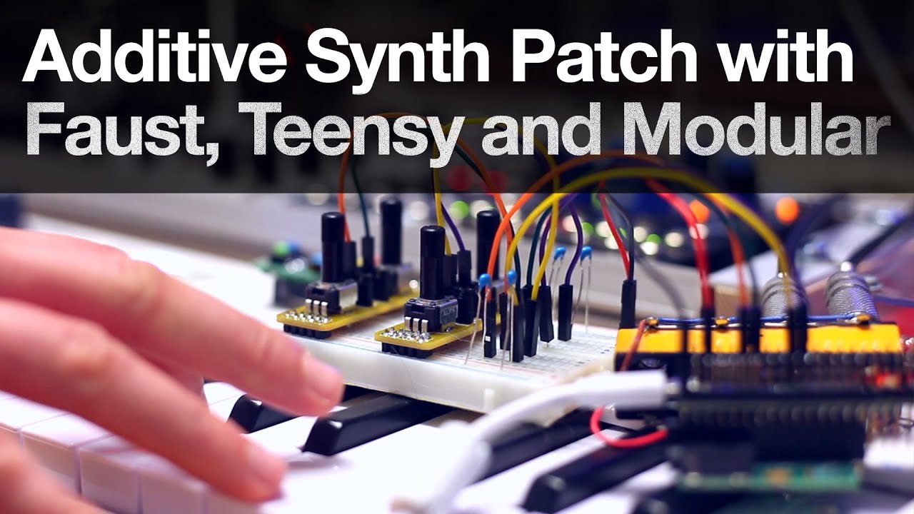
Made a neat clavinet like patch on teensy 3.6 arduino, running an additive synth patch made with Faust Functional Audio Stream DSP and the teensy audio library, controlled via midi with the Arturia Keystep and the Akai MPK Mini. The sound is then processed through the modular,...
Looking at the ESP32 for a way to play around with Bluetooth MIDI, and possible a Web interface for editing parameters as well
glacial spruce
The audio people seem to have gravitated to the Teensy platform
bleak palm
@glacial spruce teensy has the audio shield, the audio design tool and 4.0 can run at 600 MHz (not counting overclocked modes) ..
it's a pretty awesome piece of engineering but it's not so easy to derive your own designs from that
glacial spruce
I'm not sure why, they're well documented. To me, the ESP has the drawbacks that it's slower, not DSP optimized, and the nearby WiFi interface could cause interference with audio signals.
bleak palm
The MCU is something you couldn't solder without an oven, so you'd have to have a PCB prefabricated with the MCU on it
unless anyone has got a great non-bodge way to solder that by hand .. we are game!
and you'd need to get paul stoffregen's bootloader chip if you want to keep using the arduino ide
(with usb) .. I'm sure you could upload code using another method but you'd have to jump through some hoops during compilation
otherwise it's great
I wish there was a long one, a teensy 4.6 so to say
glacial spruce
Ah, SparkFun had some similar issues with their Artemis board, and ended up making a tiny daughterboard with the hard-to-solder chip and all the multilayer fine pitch routing on it.
The AdaFruit people ported Paul's audio library to the SAMD51, which comes in some easier to solder packages.
bleak palm
@glacial spruce cool so the M4 feathers have the audio library?
The Feather M4 Express has an Atmega SAMD51
glacial spruce
Yes, it is my understanding that there's a port of the audio library that runs on the M4 feathers (but I could be wrong)
bleak palm
super cool! found it!
final yoke
For fully capable DSP some sort of SoC FPGA doesn't sound so bad, but its not how do you say it.. cheap or easy.
glacial spruce
There are plenty of CPUs with DSP acceleration of one kind or another, they're not particularly expensive. Ease of use varies, but many times there are libraries to use the DSP functionality.
bleak palm
For fully capable DSP some sort of SoC FPGA doesn't sound so bad, but its not how do you say it.. cheap or easy.
@final yoke dadamachines offers this board https://dadamachines.com/products/doppler/

The doppler is a Cortex M4F Microcontroller + FPGA development board. It comes in the same tiny form factor similar to a Teensy and is open source. features • 120Mhz ARM Cortex M4F MCU 512KB Flash (Microchip ATSAMD51G19A) with FPU • FPGA 5000 LUT, 1MBit RAM, 6 DSP Cores,OSC, P...
Not cheap but still 1/10th of say a Sharc DSP Dev Board
There are plenty of CPUs with DSP acceleration of one kind or another, they're not particularly expensive. Ease of use varies, but many times there are libraries to use the DSP functionality.
@glacial spruce Yeah I cannot wait for this to arrive here https://www.kickstarter.com/projects/electro-smith/daisy-an-embedded-platform-for-music

Kickstarter
Create powerful electronic instruments and sound processors with an open source audio development board.
final yoke
don't expect nice things from kickstarter
unless its old school closed source/has guarantee to work
glacial spruce
That looks like a cool little board
final yoke
software tend to be either half assed or incomplete
bleak palm
if this latches onto Arduino, Faust and Python, the software has a good chance of being in good shape
so I'm not really concerned this won't be working
final yoke
if it has that much promise, i'd expect it to be not that great
IMO those platforms are not that great either...
bleak palm
@final yoke what do you prefer?
bleak palm
so with an STM 32 like here that would be C / C++ and the Cube IDE
yes I'm sure that will just work out of the box
final yoke
well STM32 is quite new and doesn't work and stuff but like atmel studio (AVR) and MPLAB (PIC)
 opal mesa
@final yoke When you say "STM32 is quite new and doesn't work" do you mean just in this application, their IDEs, or overall?
final yoke
the IDE chaos like thing
and how they work im sure it is really easy once you get the hang of it
(BTW not expert opinion by no means just tasted everything little by little.)
opal mesa
Yeah I don't have a ton of time in their new IDE
but it at least feels very similar to other ones I've used before.
(and eclipse-based)
The big thing that the manufacturer/professional GUIs add for IDE is (IMO) ease of debugging through JTAG/SWD
in that you can absolutely plumb everything to gdb manually and do it that way if you're familiar with it
but it sure is nice to have all the register definitions and offsets pre-done for you in a nice visible tool
 shrewd grove
With the class d 20w amp, you have screw terminals for R L and gnd. If I’m running in analog mode, I can use the RIN and LIN pins instead of the screw terminals. However which ground do I hook up from my sound fx board, AGND or GND.
Also am I right in assuming these pins still work in analog mode? I’m attaching the amp to a perf board so using the pin inputs vs the screw terminals would be ideal.
glacial spruce
Yes, the pins connect to the same signals as the screw terminals.
You'd probably hook up AGND for the signal source ground (that's what's connected to the center screw terminal).
shrewd grove
Is there an easy way to make a shielded ground wire? I noticed a get amplified hum that comes from wiggling the ground wire. The farther I move it away from the system the less hum I get. Can I shield it somehow?
final yoke
If you don't have high power, you can use coaxial cable. It's usually used for antenna signals, it has wire mesh around and a solid core cable in middle exactly as you wished. @shrewd grove
If you want to really diy it you can wrap aluminum foil around the cable 😅
shrewd grove
Does the wire mesh get tied to anything?
I always though the mesh/foil got tied to ground but if the signal running through the middle is ground, does the mesh get tied to something?
shrewd grove
It seems I need to keep the audio gnd wire away from the audio signal wire (Lin). Should I foil wrap the signal wire and tie the foil to ground as opposed to wrapping the GND wire?
final yoke
I think your audio cable should be shielded and shield part should be ground (maybe even additional ground inside too) and signal wire(s) inside.
 unique sequoia
i am looking for help learning about how to do a more complicated project then i have found on on the net
glacial spruce
There are a bunch of knowledgeable and helpful people around, but with no details on what you're doing and which parts are comfortable for you and which parts you want help with, there's not a lot we can do.
unique sequoia
i would like to start with a screen interface. is there any documentation for that?
glacial spruce
Yes, most of the documentation is for various specific screens like https://learn.adafruit.com/adafruit-2-dot-8-color-tft-touchscreen-breakout-v2
 green zodiac
Hi everyone. Nice joining this community. I love what Adafruit does : )
Hopefully one of you can help. I am trying to get the Adafruit Music Maker FeatherWing work in MIDI Synth mode with the Feather nRF52840 Express. I have followed the instructions provided at https://learn.adafruit.com/adafruit-music-maker-featherwing/midi-synth but I can't hear any sound when plugging my earphones into the audio jack. However using the FeatherWing to play a MP3 is not an issue. Any idea what could be the issue?
 glacial spruce
Could be a serial port mismatch, conflict, or the MIDI mode jumper isn't installed.
dull basalt
Here is a really cool project - a complete synth built around a Teensy 3.2 and the companion audio board. The code is all written for the Arduino. There are eleven parts in this series. I wonder how difficult it would be to convert to Circuitpython... https://www.youtube.com/watch?v=UJcZxyB5rVc
In this series we are going to build an awesome DIY Synth with a Teensy 3.2 Microcontroller and the Teensy Audio Board. In this episode we will build the circuit and give it a quick test.
DOWNLOAD the Code here: http://www.notesandvolts.com/2018/05/teensy-synth-part-1.html
W...
green zodiac
Could be a serial port mismatch, conflict, or the MIDI mode jumper isn't installed.
@glacial spruce The jumper MIDI mode is done properly because it prevented the MP3 playing function to work as described. How would I solve a serial port mismatch?
glacial spruce
I wonder if that Feather has additional serial ports, so you might need Serial1 or Serial2 or something.
bleak palm
@dull basalt it uses the teensy audio design tool which takes care of some the more intricate functinality, and that tool outputs arduino code
take a look here https://www.pjrc.com/teensy/gui/index.html
dull basalt
Yes, I know it does. I was just pie in the sky wishing anyways.
light crag
So... I got a boombox anyone wanna help me repair it
glacial spruce
Which parts do you want to have working? Usually the way I attack them is to start at the output (amplifier) and get that working, then work on whatever sources I care about (radio, cassette, CD player, whatever)
light crag
I don't know like FM and cassette soon o want to add Bluetooth
glacial spruce
Does the power supply work? Does the amplifier work?
light crag
Yes psu work
And yes I get audio from the cassette but not that great
Bit of his and distortion
glacial spruce
Hmm, might be some issues with the amplifier, or the cassette system itself. The first thing to do is figure out which. If you have some source of good line level audio, try running that into the amplifier and see if it sounds right. If so, the amplifier is fine and you can concentrate on the cassette system. If not, you need to debug the amplifier first. Luckily these things are pretty modular, so you can check out pieces individually like that.