#help-with-audio
1 messages · Page 5 of 1
 random bone
 dense plinth
Does anyone have experience getting the .wav and .mp3 audio to work on a Pico W as demonstrated on a plain Pico at https://www.youtube.com/watch?v=Lwr8LLvLRb8&ab_channel=Prof.JohnGallaugher ?
Though Thonny will compile and run the code for both .wav and .mp3, GP14 on the Pico W is completely flat lined on the o'scope. I've tried other GP pins, but get the same dormant result. The code appears to be 'playing' the file, but there is complete "silence" on the assigned PWM pin. I've tested the same Pico W with other PWM libraries for MicroPython, and confirmed that the GP14 performs PWM perfectly. Thoughts?

We'll learn that you can attach an audio jack to a Raspberry Pi Pico and Pico W with simple alligator clips, then get sound to play from the Pico through the speaker. We'll learn to do this for wav files and for mp3 files. We'll write re-usable routines that you can copy & paste any time you want to play these types of files in your own builds. ...
 late arrow
dense plinth
Does anyone have experience getting the .wav and .mp3 audio to work on a Pico W ...
late arrow
dense plinth
Does anyone have experience getting the .wav and .mp3 audio to work on a Pico W ...
todbot is the expert on that, and he has some examples here for WAV, PWM, and MP3 if you want to compare your code to his examples: https://github.com/todbot/circuitpython-tricks?tab=readme-ov-file#audio
dense plinth
Great tip, Paul. Many many thanks.
random bone
dense plinth
Does anyone have experience getting the .wav and .mp3 audio to work on a Pico W ...
Is it a Pico W or a Pico 2 W?
dense plinth
Pico W, Danh.
 weary gyro
dense plinth
Does anyone have experience getting the .wav and .mp3 audio to work on a Pico W ...
weary gyro
dense plinth
Does anyone have experience getting the .wav and .mp3 audio to work on a Pico W ...
What does the REPL say when you run the code? Anything? Maybe try adding some print statements to see if your code is even running
 frank ivy
dense plinth
Does anyone have experience getting the .wav and .mp3 audio to work on a Pico W ...
frank ivy
dense plinth
Does anyone have experience getting the .wav and .mp3 audio to work on a Pico W ...
I don't want to @ him, but I believe the guy who made that video is on here
dense plinth
Good idea, Todbot. I put print statements in during play and at the conclusion of the play. They all look normal to me, yet... silence.
Yes he is, funkymark. He's terrific. In fact, he's the one who suggested I put the issue here to the group.
random bone
dense plinth
Pico W, Danh.
did you also test on a plain Pico and it worked?
 regal jewel
I recently purchased a Adafruit Music Maker FeatherWing! which claims to be able to playback, among other things, AAC files. However, the Arduino library for it only recognizes MP3 files.
Can anyone here point me to some source code to send AAC files/data to the VS1053B chip on this board?
random bone
regal jewel
I recently purchased a **Adafruit Music Maker FeatherWing!** which claims to be ...
I see that the library skips over ID tags when playing MP3's, but I don't see that it doesn't play .aac at all. What happens when you play an AAC file? It may support only some subset of AAC.
regal jewel
@random bone , The startPlayingFile function returns true, but there is no audio output on the headphones.
void loop() {
  bool ok = musicPlayer.startPlayingFile("/Music/ABBA/The Essential Collection/1-18 Take a Chance On Me.m4a");
  if (!ok) {
    Serial.println("Failed to start Playing");
    while (true) ;
  }
  Serial.println("Playing /Music/ABBA/The Essential Collection/1-18 Take a Chance On Me.m4a");

  while (!musicPlayer.stopped()) ;
  while (true) ;

}
Good idea, danh. That's my next experiment. However, I have to get my hands on a plain Pico. They're still a little hard to come by at reasonable prices and shipping dates. I hope to have one this week.
random bone
regal jewel
<@329766224093249548> , `The startPlayingFile` function returns true, but there ...
There is discussion about issues with M4A files here: http://www.vsdsp-forum.com/phpbb/search.php?keywords=m4a&terms=all&author=&sc=1&sf=titleonly&sr=topics&sk=t&sd=d&st=0&ch=300&t=0&submit=Search. You may need to change this file or remove things from it.
 heady spade
Noob looking for help setting up audio-reactive with the new Sparkle Motion Mini board: I have WLED installed and working correctly driving the LEDs. I'm now trying to set up audio reactive since the board comes with a mic... I found the pin-out on GitHub. The 3 pins WLED needs (I assume) are clearly labeled as 9 (Data), 10 (WS), and 23 (BCLK). When I try to assign those in WLED, pins 9 & 10 don't appear in the pin selector, only 23 does. Wondering if anyone has any guiding insight to help me understand the correct pins to assign.

 torpid terrace
heady spade
Noob looking for help setting up audio-reactive with the new Sparkle Motion Mini...
torpid terrace
heady spade
Noob looking for help setting up audio-reactive with the new Sparkle Motion Mini...
The pins should be available, check out the board guide https://learn.adafruit.com/adafruit-sparkle-motion-mini/wled-audioreactive-setup
heady spade
torpid terrace
The pins should be available, check out the board guide https://learn.adafruit.c...
Thanks for sharing the guide and to those who published it! Seems I was on the right path. Though you can see in the screen shot I uploaded that the available pins to select go from 5 to 12 without any pins in between. I am not able to select pin 9 or 10 in WLED. They simply don't exist as an option. I installed version 0.15.0. Any recommendations for determining why they don't show in WLED?
torpid terrace
heady spade
Thanks for sharing the guide and to those who published it! Seems I was on the...
i don't have the board to test, but just looking at your pic vs the guide, you have selected the "generic i2s" option, vs "Type: SPH0654" in the guide... that could be a reason why the pins are not available.
dense plinth
random bone
did you also test on a plain Pico and it worked?
Ok danh. Here's the deal. Turns out the startup filename for CircuitPython is not the same as MicroPython. So the program was working all the time - I was just saving it under the wrong startup name ('main.py' vs 'code.py'). My apologies for the stupid error and many thanks for your patience.
That said.... if two versions of Python for Pico is good, perhaps four versions and architectures would be TWICE as good.. Just sayin.
random bone
dense plinth
Ok danh. Here's the deal. Turns out the startup filename for CircuitPython is no...
What was the name you were saving it under?
dense plinth
random bone
What was the name you were saving it under?
I was saving it as 'main.py' as I learned to do with MicroPython. Doh.
dense plinth
random bone
and there was a code.py, so... 🙂
Yep. Both files were there. You are a true Pico whisperer, Danh. I am glad you are there for us.
random bone
np!
heady spade
torpid terrace
i don't have the board to test, but just looking at your pic vs the guide, you h...
Updated to the nighly build just posted and all works now. 🙂 This explains why the pins weren't showing up for me:
Thanks again!
https://github.com/Aircoookie/WLED/releases/tag/nightly


GitHub
Changelog
nightly (2025-01-27)
Full Changelog
Implemented enhancements:
[Feature Request][WebUI][Audioreactive] Add an indicator to the UI if audio packets are received #4515
Add option to customi...
 echo hedge
request for CP synthio help on the forum: https://forums.adafruit.com/viewtopic.php?p=1044226#p1044226
 rugged fractal
Hello folks! This might have come up a gazillion times already, but I tried looking at online sources and nothing resolved my issue. I'm looking for help adding audio to my Pi Zero project. I followed LadyAda's tutorial (https://learn.adafruit.com/adding-basic-audio-ouput-to-raspberry-pi-zero/pi-zero-pwm-audio) — I added the dtoverlay=pwm-2chan,pin=18,func=2,pin2=13,func2=4 line to /boot/config.txt, built a filter, and connected headphones to the jack, but all I'm hearing a bunch of noise. I'm not sure what might be useful for troubleshooting, so here's a bunch of info.
-
The project is a portable console, running RetroPie on a RPi Zero 2W with a 2.8" PiTFT (resistive) over SPI and pushbuttons connected to GPIO for the controls. I have nothing else connected — no HDMI displays, no keyboard. I do everything over SSH on my laptop.
-
The noise I'm hearing is kind of squeaky, it sounds like there is some white noise and on top of that some additional higher-pitch noise.
-
Some of the sound seems to come through, but as a faint background. This includes, for example, clicking sounds on keypresses (SSH) and when I adjust the volume via alsamixer. I tried
aplaying something but couldn't hear much. -
I tried hooking up my headphones directly to GPIO 13 and 18 using alligator clips and it sounds roughly the same. My first thought was the filter is doing nothing and I must have screwed up the wiring, so I tried rebuilding it on a breadboard and I got the same result. So either I fundamentally misunderstood the schematics or the wiring is not the issue.
-
If I remove the dtoverlay for the PiTFT from
/boot/config.txt, the high-pitch squeak goes away, but I'm still left with a lot of white noise. -
If I
sudo raspi-configand then navigate toSystem Optionsand thenS2 Audio, one of two things happens in an apparently random way. Either I get a message that no sound cards were found, or the config screen disappears for a moment and reappears on the main menu.

Get your Pi Zero singing
The fact that removing the display dtoverlay from the config file changes the noise makes me think that there might be other software components that are trying to use GPIOs 13 and 18, maybe that's what I'm hearing? Or perhaps there is some configuration I'm missing?
Any suggestions appreciated, thanks!
 desert fog
The display overlay has traditionally used every pin on the header, so that's a possibility.
rugged fractal
Ouch. I see. But in that case, shouldn't removing that overlay fix the sound? Also, shouldn't I be surprised that the controls through push-buttons connected to GPIO are working?
rugged fractal
Update: I think the problem might be that the approach I'm taking worsk for the original Raspberry Pi Zero, but not for the 2W.
 restive hornet
Can someone please help me understand what impact having PSRAM has on an Arduino project? I'm looking at QTPY boards, specifically https://www.adafruit.com/product/5700 and https://www.adafruit.com/product/5426 .. The '5700 states it has 4M Flash, 512K SRAM, and 2M PSRAM, while the '5426 has 8M flash, 512K SRAM, and 0 PSRAM. Generally, I think "more is better" in terms of Flash and SRAM, but I don't understand the impact of PSRAM.

The ESP32-S3 has arrived in QT Py format - and what a great way to get started with this powerful new chip from Espressif! With dual 240 MHz cores, WiFi and BLE support, and native USB, this ...

The ESP32-S3 has arrived in QT Py format - and what a great way to get started with this powerful new chip from Espressif! With dual 240 MHz cores, WiFi and BLE support, and native USB, this ...
restive hornet
restive hornet
Can someone please help me understand what impact having PSRAM has on an Arduino...
Answering my own question -- I asked ChatGPT to help me understand, and this is what it came up with in a summary. Passing it on here in case others have the same question.
 echo hedge
restive hornet
Answering my own question -- I asked ChatGPT to help me understand, and this is ...
echo hedge
restive hornet
Answering my own question -- I asked ChatGPT to help me understand, and this is ...
Looks accurate to me
random bone
restive hornet
Answering my own question -- I asked ChatGPT to help me understand, and this is ...
It is not clear to me in what circumstances the Arduino core uses the PSRAM. There are explicit heap allocation routines like ps_calloc() that allocate in the PSRAM. I don't know if there is any invisible or automatic allocation in the PSRAM. Some casual websearching did not get me that answer.
restive hornet
Hah. I meant to post this to help-with-arduino, not help-with-audio. My bad!
 stray loom
restive hornet
Can someone please help me understand what impact having PSRAM has on an Arduino...
stray loom
restive hornet
Can someone please help me understand what impact having PSRAM has on an Arduino...
is this helpful ?

How to get the most from your Arduino Memory
 glad grail
I’m using the guide and code from Adafruit for mp3 playback using the pi pico. I’d like to add a button to the code to play the mp3 files. I started getting it to work but it only plays the file once thru completely then every other time it only partially plays the mp3 files. Has anyone had this same experience?
 stable ridge
glad grail
I’m using the guide and code from Adafruit for mp3 playback using the pi pico. I...
stable ridge
glad grail
I’m using the guide and code from Adafruit for mp3 playback using the pi pico. I...
i had issues on repeating audio playback too and just made it do a hard reset when it was done via code
 raven arrow
Im looking for a microphone level preamp to line out using 3.5 mm connectors. Need it portable. Does Adafruit sell a preamp board that i could use. I'm going from a Rode shotgun mic to a zoom handy recorder. Not enough signal to make it work. Has to be line level. Whatever anyone can chime would be great. Thanks
random bone
raven arrow
Im looking for a microphone level preamp to line out using 3.5 mm connectors. Ne...
Which Zoom recorder are you using ... H1? and which mic? Some Zooms take mic-level inputs.
The mics are usually XLR. Some Zoom's have an XLR connector meant for mics. Otherwise normally the mic would go into a mic preamp in a box. But plain mic preamps are rare, because most people want something fancier, or their recorders already have mic preamps. E.g., an "audio interface" like a Scarlett will have one or more mic inputs, and and A/D and USB so you can record on a laptop, etc.
If the Zoom has a mic input but the gain on its mic preamp isn't enough, there are XLR in-line boosters, e.g.: https://www.sweetwater.com/store/detail/MicBoostCM1--klark-teknik-mic-booster-cm-1-dynamic-microphone-booster
There are a few boxes like this: https://www.fullcompass.com/prod/012210-rolls-mp13-1-channel-mini-microphone-preamplifier which are what you're asking for, but if you're going to spend that much, you might spring for a low-end interface for the same price or less https://www.fullcompass.com/prod/605884-presonus-audiobox-go-ultra-compact-mobile-audio-interface. There are many such and you should read reviews
 vestal frigate
Has anyone found a list or source for interesting audio projects?
I'm trying to find parts lists since I'll be making an order soon and some fun and difficult audio focused projects would help with that
random bone
vestal frigate
Has anyone found a list or source for interesting audio projects?
I'm trying to...
https://learn.adafruit.com/search?q=audio and similar search for music, synth, midi will give you a LOT of projects
 modest island
Another question:
When using the rp2040 propmaker feather or maybe a raspberry pi etc.
I believe the max. output for speaker is 3W or so?
What if I want to attach a very big speaker or sound system? Is there some module/breakout board I could use instead?
frank ivy
modest island
Another question:
When using the rp2040 propmaker feather or maybe a raspberry ...
You could attach powered speakers and/or a secondary amplifier. IIRC adafruit doesn't carry any high output audio amplifiers, but you could also try ask an engineer.
 fossil wolf
hello, i'm trying to connect a PAM8302 audio amplifier to my raspberry pi pico using micropython. Is there any tutorial out there to the code?
torpid terrace
fossil wolf
hello, i'm trying to connect a PAM8302 audio amplifier to my raspberry pi pico u...
There is no specific code for the PAM8302, it's just an amplifier. This is the breakout board guide for the wiring https://learn.adafruit.com/adafruit-pam8302-mono-2-5w-class-d-audio-amplifier and some examples of how to play audio on the rasp pi pico https://learn.adafruit.com/mp3-playback-rp2040 but in CircuitPython.
No idea about micropython.
 glacial spruce
modest island
Another question:
When using the rp2040 propmaker feather or maybe a raspberry ...
glacial spruce
modest island
Another question:
When using the rp2040 propmaker feather or maybe a raspberry ...
You can run big speakers with 3W. In fact they'll be louder than smaller speakers at the same power, as big speakers are more efficient.
 timber plinth
hey yall, im pretty new to this sort of thing, but ive had pretty good progress so far and am now at a loss. i have a soundFX board set up to trigger off pin 9, and i have a list of 7 different sounds for it to randomly play through, labeled as T09RAND1.ogg etc. problem is, it wont play any of them. if i set one to just T09 itll play the one sound just fine, but i cant get the whole playlist to work. i dont exactly understand what im missing here.
its normally powered off of 2 AAA batteries (im recreating a 20 something year old toy for my disabled sister) but i have a power supply feeding it 3.7 to test with when it acts funny. it doesnt like to boot every time and im sure thats the AAA batteries, but ill work on that when i get it ironed out
 restive glen
Using the new I2C\DAC breakouts (PCM510x) with RPi (Zero W)
restive glen
I'm interested in using the new I2S\DAC breakouts (PCM510x) with RPi (Zero W) on bookworm. Is there an existing guide I can use to get this working?
 heady crown
restive glen
I'm interested in using the new I2S\DAC breakouts (PCM510x) with RPi (Zero W) on...
heady crown
restive glen
I'm interested in using the new I2S\DAC breakouts (PCM510x) with RPi (Zero W) on...
I don't believe there's a guide to use that specific product with a Raspberry Pi Zero. However, you might be able to adapt the guide for another I2S DAC to the one you're using. Try following the Raspberry Pi instructions of https://learn.adafruit.com/adafruit-max98357-i2s-class-d-mono-amp.
restive glen
I currently have a "Stereo Speaker Bonnet" on a PIZeroW. Could I just parallel off that board onto the new PCM510x I2S\DAC breakout board to additionally get a line-out (5v, GND, pins 7, 23, 25 for BCLK, LRCLK, DIN, respectively)? Would paralleling of 7, 23, 25 likely load those outputs down and destabilize the circuits?
weary gyro
restive glen
I currently have a "Stereo Speaker Bonnet" on a PIZeroW. Could I just parallel o...
Should be fine
restive glen
Thx! Another question about the "Speaker Bonnet"... I recall reading about the "+3, +6, +9 gain" traces\pads, but I can't find that info any more. Anyone know where I can find info on them?
random bone
restive glen
Thx! Another question about the "Speaker Bonnet"... I recall reading about the "...
I haven't found any documentation on the pads. That is an omission that should be corrected.
restive glen
The schematic at https://learn.adafruit.com/adafruit-speaker-bonnet-for-raspberry-pi/downloads shows gain at +9dB, which is what I wanted to know (default gain). Not clear on what to do with the pads to effect +3 or +6.

Turn it up!
torpid terrace
restive glen
The schematic at https://learn.adafruit.com/adafruit-speaker-bonnet-for-raspberr...
I looks to me like the gain is +6db at the moment, since the trace is connected between the middle and left pad
If you cut that trace, then the gain is the default +9db
If you cut the trace to the left, and solder the middle and right pads together, the gain would be +3db
based on this

and the explanations in the max98357 guide https://learn.adafruit.com/adafruit-max98357-i2s-class-d-mono-amp/pinouts#gain-2693327
random bone
@restive glen @torpid terrace I have added a Gain section to the original guide https://learn.adafruit.com/adafruit-speaker-bonnet-for-raspberry-pi/pinouts#gain-3196526, but haven't yet done a photo detail, because I'm not familiar with how to do that.
restive glen
@random bone That's a clear discription. @torpid terrace the link you provided may be where I had read about gain previously. Thx.
 crisp sable
Hey all does anybody have a recommendation for good headphone wire that wont break easily? Got a bad wire on my headset. Also earbuds if anyone has any recommendations that sound good for a decent price i wouldnt mind changing out the ones that are on it
 spiral mica
Hi all! Having a lot of trouble getting my braincraft hat to play audio from a raspberry pi and tried this guide: https://learn.adafruit.com/adafruit-braincraft-hat-easy-machine-learning-for-raspberry-pi/audio-setup and troubleshooting but had no luck
The card shows up like this after running sudo aplay -l:
card 1: wm8960soundcard [wm8960-soundcard], device 0: bcm2835-i2s-wm8960-hifi wm8960-hifi-0 [bcm2835-i2s-wm8960-hifi wm8960-hifi-0] Subdevices: 1/1 Subdevice #0: subdevice #0
However, I do not hear any sound when plugging in an audio jack to either the braincraft hat or the Rasp Pi. Any ideas? Thank you!
spiral mica
crisp sable
Hey all does anybody have a recommendation for good headphone wire that wont bre...
The Audio-Technica M40x worked well for me. It’s got a removable cable which is pretty durable, but if it breaks you can easily buy a cable to replace it. Main disadvantage is they are not well suited to being shoved in bags and aggressive handling can cause the connector to the pads to break.
 cursive rune
looking at I2S - if I'm using 3.3v uC, will I notice a difference between PCM5102 and UDA1334A?
weary gyro
cursive rune
looking at I2S - if I'm using 3.3v uC, will I notice a difference between PCM510...
No, I don’t think so
 thorny yoke
I'm designing an embedded project for something like a nautical westminster clock, that will play bell sounds at top and bottom of the hour. I am not committed to Arduino or Raspberry Pico platforms, although I'm more comfortable in Arduino.
For sound I see the "Adafruit "Music Maker" MP3 Shield for Arduino w/3W Stereo Amp - v1.0", which looks like it is perfect for my application. I also see the "Adafruit Music Maker FeatherWing - MP3 OGG WAV MIDI Synth Player" which would give me a smaller footprint.
As far as differences between the two options, is the biggest one that the featherWing doesn't have onboard amplification? So I would need something like the "Stereo 2.1W Class D Audio Amplifier - TPA2012" to drive the clock's speakers for the bell sound? Are there other capabilitiy differences that I can read up on?
thorny yoke
update I think I mooted my own question. There is the "Music Maker FeatherWing w/ Amp - MP3 OGG WAV MIDI Synth Player - Stereo 3W Amplifier" . I think that is the right direction for what I'm attempting.
 solid silo
Hi all! Huge fan of CircuitPython, but for some reason I’ve never chatted in this server.
I make a eurorack module (Uncertainty) that works with CP. Been writing scripts for it for years.
Recently I started experimenting with CP audio and somehow worked on a sampler for a month before finding out it’s capped at 22 kHz. It’s 22 kHz on a samd21 and an rp2350.
Is there somewhere that explains this decision? Is there somewhere in the source for CP that this can be changed? (I looked and couldn’t find it)
There are so many things that CP can do with audio that almost don’t make sense below 44.1 kHz. Like reverb. It makes me think I’ve misunderstood something along the way.
weary gyro
solid silo
Hi all! Huge fan of CircuitPython, but for some reason I’ve never chatted in thi...
Can you describe how it's capped for you at 22kHz for RP2350 or RP2040? I regularly run my I2S DACs at 44.1kHz sample rate, using stuff like:
SAMPLE_RATE = 44100
CHANNEL_COUNT = 2
BUFFER_SIZE = 2048
audio = audiobusio.I2SOut(bit_clock=board.GP20, word_select=board.GP21, data=board.GP22)
mixer = audiomixer.Mixer(sample_rate=SAMPLE_RATE, channel_count=CHANNEL_COUNT, buffer_size=BUFFER_SIZE)
mywav = audiocore.WaveFile("amen3_44k_s16.wav")
mixer.voice[0].play(mywav)
Also, very cool module!
solid silo
This exactly what I was doing but it didn't sound right to my ears so I paired down even further to:
a1 = audiocore.WaveFile(open("samples/niamos!.wav", "rb"))
a1.sample_rate = 44100
audio.play(a1, loop=1)```

That third line shouldn't even be necessary as far as I can tell. I've tried it with and without it. Either way it sounds the same as if I make a 22 kHz version of the source file.

*I decided to switch from my own samples to a track from Andor with a lot of interesting spectra that disappears at lower sampling rates*

This is one of the few places I've found that mentions a limit: <https://learn.adafruit.com/circuitpython-essentials/circuitpython-audio-out#play-a-wave-file-2994862>
> You can use any supported wave file you like. CircuitPython supports mono or stereo, at 22 KHz sample rate (or less) and 16-bit WAV format…I could do some audio analysis in Max/MSP to go a step further into confirming this, but it feels like a design decision.
Also, thanks @weary gyro !
weary gyro
solid silo
This exactly what I was doing but it didn't sound right to my ears so I paired d...
That's an old document, meant for SAMD21 ("M0")-class devices.
On faster devices like the RP2350, you can go much higher on the sample rate. When using the more complex audio tools of CircuitPython (e.g. audiomixer.Mixer, audiofilters, audiodelays, synthio), you will set a fixed sample_rate and channel_count and all inputs that feed into it, including audiocore.WaveFile objects must have a matching sample_rate & channel_count.
So, you'll need to re-encode any existing WAVs to 44.1kHz if you want to use them at that rate with the Mixer and audio effects. A quick way to re-encode on the command-line is with sox like: sox loop.mp3 -b 16 -c 2 -r 44100 loop.wav to make a stereo 44.1kHz WAV.
The audiomixer.Mixer is really handy because in addition to letting you play multiple simultaneous sounds and set levels for each, it has a buffer_size argument which, when set to 1024 or greater, helps prevent glitches when other activities (like USB accesses) are vying for CPU
Here's an example of a 44.1kHz WAV being played on an RP2350: https://www.youtube.com/watch?v=nyv7XlQ1d00
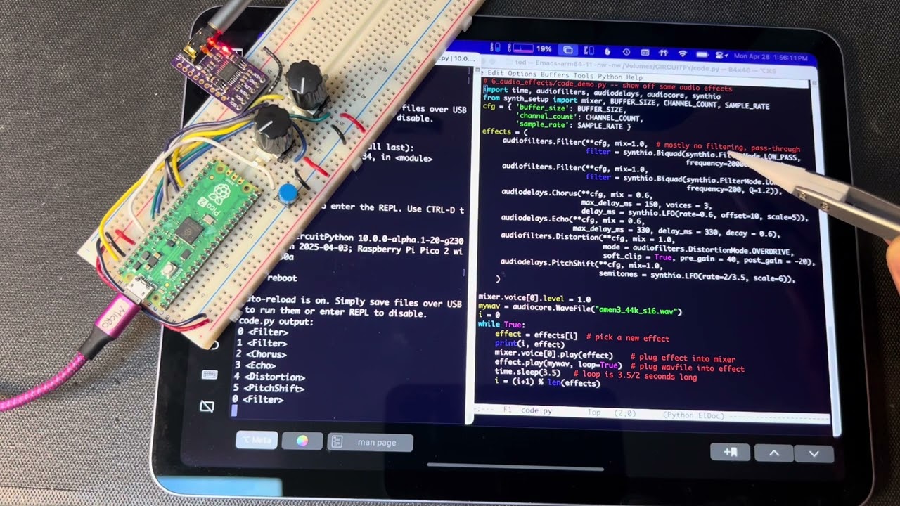 solid silo
Should the code I shared operate at 44.1 kHz? In other words, what is the sampling rate when not using those more complex tools?
weary gyro
solid silo
Should the code I shared operate at 44.1 kHz? In other words, what is the sampli...
It can be whatever you like. I usually code synthio stuff on RP2040 so I'll start at 44100 and then downshift to 30000 or 22050 as I end up finding myself running out of resources. But doing that sample rate changing when dealing with WAVs is annoying so I often stick with 22050 when I'm doing WAV-stuff
solid silo
I’ll keep investigating. I am not getting 44100 playback with a 44100 wav. And I’ve tried the same code as you. Maybe I simply have distortion in my dev setup that’s limiting the clarity of the audio signal.
But it’s fairly minimal.
 weary gyro
solid silo
I’ll keep investigating. I am not getting 44100 playback with a 44100 wav. And I...
weary gyro
solid silo
I’ll keep investigating. I am not getting 44100 playback with a 44100 wav. And I...
Hmm, well if it's working at all with your WAV at 44.1kHz 16-bit and audiomixer.Mixer set the same, then CircuitPython is doing audio at 44.1 kHz 16-bit to the DAC. I'd then start to suspect the DAC, the TRS cable, or whatever is your line-in receiver.
If you're driving headphones directly, the PCM5102 is not spec'd for that, but it'll work (I do it all the time) if they're higher-impedance ones like earbuds and you set the mixer volume down with something like mixer.voice[0].level = 0.25
I've not tried the Adafruit PCM5102 board yet but it looks pretty similar to the cheapie PCM5102 DACs I normally use.
solid silo
It’s going into a 4ms Wav Recorder eurorack module then directly to a nice British amp and monitors.
That’s good info to know!
weary gyro
solid silo
It’s going into a 4ms Wav Recorder eurorack module then directly to a nice Briti...
That sounds like a good setup, so I wouldn't suspect it!
I may have one of those DACs, I'll poke around tomorrow and try it out if I have one.
Good luck in your own research. Seems like it's almost working
solid silo
Thanks!
solid silo
Reading your synthio tutorials. These are fantastic
weary gyro
solid silo
Reading your synthio tutorials. These are fantastic
Thanks! I got side-tracked and am not done with it yet, so it kind peters out around the audioeffects section 🙂
weary gyro
solid silo
Thanks!
I did find my Adafruit PCM5102 module but I couldn't find my Metro RP2350 so I used a Pico2. Here's a quick demo of playing a WAV file at 44.1 kHz @ 16-bits: https://gist.github.com/todbot/16ebcfb2b3d1d4934d4ea5a3261898be In the comment of that gist is a recording of the audio output of the DAC straight into my phone with an "okay" audio interface
solid silo
Oh cool! I just did the same thing and found a roll-off around 17khz, which is fine. I’ll check out your recordings
I guess there’s no problem with CircuitPython or the way I’m using it
Not sure why it doesn’t sound particularly good to our ears. But it’s not cp
weary gyro
solid silo
Oh cool! I just did the same thing and found a roll-off around 17khz, which is f...
wow if you can hear to 17 kHz then you've got much better ears than me! But yeah if it works and you're looking at frequency graphs, to me that's in the realm of the DAC chip, the board its on, cabling, or the recording setup: all analog electrical engineering concerns 🙂
There are some config pins on the PCM5102 you may want to look at, particularly the "DEMP" and "FLT" pins. Those are brought out on the Adafruit board and I think they're set up correctly for normal use
solid silo
first is playing from my mac into the 4ms wav recorder. second is from the lil dac board


they both roll off around 17k so that rolloff isn’t the difference i’m hearing
oh yeah, been meaning to play with those. thanks again!
solid silo
So just to wrap this up. My audio complaints seem to be caused by a noisy module in my modular setup that was adding noise to everything. I go straight to my amp and it sounds gorgeous. Doing stereo delays at 16/48 with pypthon! These tools are just amazing
solid silo
Was able to implement some effects without issue, but got stuck on filtering. Every filtering example I can find works with filters within the context of a synthesizer. I'm not sure if that a constraint.
This is the code and result I currently have.
 weary gyro
solid silo
Was able to implement some effects without issue, but got stuck on filtering. Ev...
weary gyro
solid silo
Was able to implement some effects without issue, but got stuck on filtering. Ev...
Looks like you're on CircuitPython 9.x. There have been many changes and improvements to the audio effects.
Try CircuitPython 10.0.0-alpha.6 or above instead.
solid silo
Will do!
solid silo
LOL! That made the above code work perfectly. CircuitPython 10.0.0-alpha.6
solid silo
I’ve never had code go from crashing inexplicably to working perfectly with only an update. This should happen more
weary gyro
solid silo
I’ve never had code go from crashing inexplicably to working perfectly with only...
There has been so much great work by @rare torrent & @pine iglooin the last several months on the audio effects, it's really exciting, but it does mean you need to be on the bleeding edge. Just a few weeks ago, audiofilters.Phaser and audiofreeverb.Freeverb were added. I've not checked if they're in alpha-6 yet
solid silo
It’s incredible work. Very excited to be working with CircuitPython rn
 pine igloo
So glad to see our new modules are getting some love! 😄
solid silo
Does CircuitPython automatically detect the presence of external PSRAM and use it for audio buffers?
I’m using an RP2350 with 512 KB of built in memory and an external 8 MB PSRAM module.
torpid terrace
solid silo
Does CircuitPython automatically detect the presence of external PSRAM and use i...
The extra RAM needs to be specified in the board definition, when building the board specific CP image.
If it's defined there, it will be used for audio buffers, yes.
solid silo
Interesting. The Metro RP2350 is available both with and without the extra RAM and they don't make two different images available for each CircuitPython version. So I suppose it's not in the board definition. I'll check GitHub for more
Actually, it appears to be in the board definition!
Mwahahah! I have all the RAMs!
random bone
I think if it is not there it will quietly fail to read the PSRAM chip device id and leave _psram_size as 0.
weary gyro
torpid terrace
If it's defined there, it will be used for audio buffers, yes.
Does the PSRAM show up in gc.mem_free()?
torpid terrace
weary gyro
Does the PSRAM show up in `gc.mem_free()`?
It's being added to the heap, so yea, it should
solid silo
and it does. 8,134,064 bytes of free memory :)
 narrow plaza
Hello; I have a QT PY ESP32. Wanted to record and play with audio using a mic I2S, product code 3421, SPH0645 breakout board.
Is the any circuitpython code to get signals from the mic?
late arrow
narrow plaza
Hello; I have a QT PY ESP32. Wanted to record and play with audio using a mic I2...
I used that mic for an audio reactive project - if you want an example of how to setup the mic, you can look at my code, but I didn't use it to record, but might get you started: https://github.com/prcutler/speakerstand-lights/blob/main/code.py
 bold latch
Hi, I'm looking to use this amp (https://learn.adafruit.com/adafruit-max98357-i2s-class-d-mono-amp/overview) for an internet radio project.

Add digital-quality audio with a class D amplifier for easy sound!
My question is; How do I limit the output wattage so I don't blow up the tiny speaker in the radio I'm using?
The speaker doesn't have a rating stamped on it, but other models of that particular radio seem to have 8-Ohm 0.45W speakers.
I found this a bit further into the guide, is it as simple as powering it off 3.3v to limit it to 0.8/0.6W at max gain? So if I run it at a lower gain, it should be alright?

 obsidian carbon
bold latch
I found this a bit further into the guide, is it as simple as powering it off 3....
obsidian carbon
bold latch
I found this a bit further into the guide, is it as simple as powering it off 3....
Not familiar with this chip, but also saw a gain pin able to reduce gain to 3db - might that be an additional option?
 next tapir
Hi
I am able to use one of the examples of tinyusb for rp2040 as UAC2.0 audio output device and its working as expected.
Since this is UAC2.0 it works fine on PC, if I want to make this work on PS5 then I need it to be UAC1.0 device.
Since tinyusb only has UAC2.0 implementation, where should I start from to modify it into UAC1.0?
If anyone already implemented similar functionality please let me know
 tepid grove
next tapir
Hi
I am able to use one of the examples of tinyusb for rp2040 as UAC2.0 audio ou...
tepid grove
next tapir
Hi
I am able to use one of the examples of tinyusb for rp2040 as UAC2.0 audio ou...
I would ask and document your ideas + progress in an issue on the tinyusb repository, that way when the maintainer gets a chance then they can advise you as best as possible (in case they previously investigated), and equally other members of the community
next tapir
Hi @tepid grove
I found pico-playgrounds repository which has usb sound card implementation. I used that and able to emulate the device as UAC1.0 sound card and tested both on pc and ps5 and I am getting good audio output.
Just an update, I am using sparkfun WM8960 codec for audio output. I will document the wire connections and will update my repo with updated code so that others can use too.
Meanwhile I am now trying to implement microphone input functionality in a similar way. I am just confused what wire I need to connect to what pin on WM8960 codec for receiving microphone input and passing data to rp2040.
If you or anyone else happen to know that then that would be awesome.
I am using headset with built in microphone, I will be connecting it to TRRS jack which connects to WM8960 codec which further connects to rp2040.
https://learn.sparkfun.com/tutorials/audio-codec-breakout---wm8960-hookup-guide/all
Once I complete this implementation and testing of current objective then I can start looking into TinyUsb for UAC1.0 implementation since many devices and consoles still uses UAC1.0.
 idle fjord
Hello, I’m trying to output audio from the feather rp2350 HSTX, and the TLV320DAC3100,but I can’t get past the Arduino example code. Eventually I want to use decoded PCM audio, but for now I was just trying to use the example code to test the boards but it’s not outputting audio to the headphone jack. Sometimes it says all the I2C configs fail, but other times it configs without error but just doesn’t play the sine wave example. Any idea why or how to fix it? I am using the pins in the example as well. https://learn.adafruit.com/adafruit-tlv320dac3100-i2s-dac

An I2C configurable I2S DAC
weary gyro
idle fjord
Hello, I’m trying to output audio from the feather rp2350 HSTX, and the TLV320DA...
I had similar problems with this part and it was because I wasn’t pulsing low the RST pin. This is required for reliable operation. The Arduino example in the Learn Guide does not show this.
Edit: the example in the library does show reset tho https://github.com/adafruit/Adafruit_TLV320_I2S/blob/main/examples/basicI2Sconfig/basicI2Sconfig.ino

GitHub
Arduino library for TLV320-based I2S DAC/ADC. Contribute to adafruit/Adafruit_TLV320_I2S development by creating an account on GitHub.
idle fjord
weary gyro
I had similar problems with this part and it was because I wasn’t pulsing low th...
What ended up working for me was using the setup code in the library example and just going from there - but I also have a PCM5102 that i'm also going to play around with which seems to work well with any I2s audio library and requires no additional I2C
next tapir
This audio codec looks cool and also has both audio output and input functionality. If anyone used the audio input functionality please let me know, might pick this up for replacement of wm8960 codec if audio input doesn't work out
 young forum
@wispy mortar i don't suppose you have a g.722.1 decoder to go with that encoder do you?
i have a snxrom from a different toy and it contains (accoring to the AU headers) streams with formats 12kHz/16kbit, 8kHz/12kbit and 16kHz/32kbit - and these don't match anything from g.722. but the fact it's a snxrom file suggests it can't be all that different?
 wispy mortar
@young forum no, I didn't develop a decoder in that project.
 rose elm
Dumb Circuitpython question: I just got my 2025 Magtag, and while I can get a simple digitalio value = True/False loop to make noise, so the speaker works, but... how do I play, ideally, an MP3? Failing that, a WAV? Failing that, a low-RAM way to play tones? All the examples I find use AudioOut from libraries that aren't available in 10.0 beta 2 for Magtag, like audioio. I have audiobusio and audiocore, board and digitalio imported. Even if I try adafruit_magtag.Peripherals.play_tone(), the examples show 2 parameters, but the magtag seems to want 3?
late arrow
rose elm
Dumb Circuitpython question: I just got my 2025 Magtag, and while I can get a si...
todbot has some examples you might be able to use or adapt: https://github.com/todbot/circuitpython-tricks#making-simple-tones
rose elm
Thank you: for a WAV file, the audiobusio example is:
import board, audiobusio, audiocore
audio = audiobusio.I2SOut(bit_clock=board.GP0, word_select=board.GP1, data=board.GP2)
audio.play( audiocore.WaveFile("laser2.wav") )
What pins would those be on the Magtag 2025? Or do I need to buy something like the https://www.adafruit.com/product/3885, which I'd plug into the A1 or D10 STEMMA 3-pin connector... and then what would I use for the Magtag? The example for that product is a "cpx" module from the circuitplayground express, which doesn't give me quite enough to go on.
weary gyro
rose elm
Thank you: for a WAV file, the audiobusio example is:
import board, audiobusio, ...
The ESP32 DAC works now in CircuitPython, so you should be able to use audioio to create an audio device to feed WAV files to. So you should be able to do:
audio = audioio.AudioOut(board.SPEAKER)
audio.play(audiocore.WaveFile("laser2.wav"))
Oh weird, I just noticed audioio is removed from CirPy 10 for MagTag? Why is that?
Edit: huh I guess not. I just tried 9.2.8 on my MagTag and get RuntimeError: Failed to create continuous channels: not found even though from the schematic board.SPEAKER is hooked up to IO17/DAC1
weary gyro
rose elm
Dumb Circuitpython question: I just got my 2025 Magtag, and while I can get a si...
The simplest way to play tones on ESP32 is with PWM. You can use the simpleio library for this (in the bundle). On the MagTag, using it would look something like:
import board, digitalio, simpleio
speaker_enable = digitalio.DigitalInOut(board.SPEAKER_ENABLE)
speaker_enable.switch_to_output(value=True)  # turn on speaker amp
simpleio.tone(board.SPEAKER, 440, 2)   # play a 2 second tone at 440 Hz
audioio should be on for ESP32-S2. there was a change in 10.0.0 mpconfigport.mk from CIRCUITPY_AUDIOIO = 1 to CIRCUITPY_AUDIOIO ?= 1, and that appears not to be overriding the default AUDIOIO ?= 0 earlier in the file. I'll open an issue on this.
rose elm
Thank you both so much! I've got simpleio tones working, but being able to play MP3 or at least WAV files would be very very nice.
 fair cedar
Does anyone know about EE
I've got I2S board, and I do not know how to connect AGND
I have external mixer, so should I just connect AGND to COM of +-15V DC-DC?
 weary gyro
AGND in this situation means the common voltage reference for the Lout and Rout pins next to it. It’s those three lines that are also wired to the headphone/line out jack on that board. Do not wire anything to +-15V on that board. Use the jack to wire to your mixer
Adafruit makes a very similar board you can get wiring tips from https://learn.adafruit.com/adafruit-i2s-stereo-decoder-uda1334a/pinouts

A nice and fully-featured I2S stereo DAC for you!
pine igloo
For all you CircuitPython audio folks out there, we've finally got panning added to audiomixer.AudioMixer! https://docs.circuitpython.org/en/latest/shared-bindings/audiomixer/index.html#audiomixer.MixerVoice.panning + you can use mono samples with stereo output now (download the absolute newest build to use it)
 signal aspen
Hi folks I'm using this code and for some reason I get no audio at all, when I change the volume in windows the serial monitor says the following. Clearly I'm missing something but I don't know what.
17:31:57.072 -> Set channel 1 volume: 0 dB 17:31:57.072 -> Set channel 2 volume: 0 dB 17:31:57.072 -> Get Volume of channel: 1 17:31:57.072 -> Get Volume of channel: 2 17:31:57.167 -> Get Volume of channel: 1 17:31:57.167 -> Get Mute of channel: 1 17:31:57.167 -> Get Volume of channel: 1 17:31:57.167 -> Get Mute of channel: 1 17:31:58.096 -> Get Volume of channel: 1 17:31:58.096 -> Get Volume of channel: 2
GitHub
Hi, Firstly thank you for all your hard work on this port and Arduino audio tools. I am trying to get working a RP2040 to be a simple USB interface and transfer audio via i2s to a DAC. Eventually t...
weary gyro
signal aspen
Hi folks I'm using [this code](https://github.com/pschatzmann/Adafruit_TinyUSB_A...
Have you ever had the I2S DAC working (e.g. generating a simple waveform out) to verify the connections are good?
signal aspen
Yeah it works with the example in Earl's rp2040 stuff
weary gyro
Hmm well that was my one suggestion. I’ve had a few of those PCM5102s not work because I forget to wire SCK to gnd (or do the solder jumper). Hoped it was an easy fix like that
signal aspen
ah yeah I suspect it's my setup if anything 🙁 I'll take another run at it some other time 🙁
like surely the volume shouldn't say 0db
fair cedar
weary gyro
AGND in this situation means the common voltage reference for the Lout and Rout ...
Yeah I will wire AGND to COM on +-15V supply I have.
Also to prevent breakage I guess I will voltage follow the Lout/Rout
 icy scarab
Alright, so I'm very new to all of this, but here's the jist of what I'm trying to do. Plan is a Raspberry Pi Zero W which will be inside a helmet. Its running some fans, a servo, some sensors to trigger a few things.
In this helmet I also have a 10W PA system using an electret mic and a speaker. Right now this is a separate circuit.
I also also have a headset with a pair of microphones on either side of my head, and some speakers for my ears, so I can hear around me. This is also its own circuit.
What I'd like to do is have both of these systems run off the RPi, but I don't want to accidentally cross the PA stream with the Ears stream, if that makes sense?
 arctic rover
icy scarab
Alright, so I'm very new to all of this, but here's the jist of what I'm trying ...
arctic rover
icy scarab
Alright, so I'm very new to all of this, but here's the jist of what I'm trying ...
So how do you want to split the 2? I mean so how many speakers and mics you got? 2 speakers and 3 mics? You can just wire them all up by them selves? What do you mean by crossing?
icy scarab
arctic rover
So how do you want to split the 2? I mean so how many speakers and mics you got?...
3 speakers, 3 mics.
My concern is routing the sound picked up by the hearing mics into the PA speakers and blasting the folks around me with feedback, or trying to talk to the folks around me and deafening myself instead.
Im not familiar with all of this, like I said, so I just want to make sure I route the inputs and outputs correctly, and I dont know if I can do that, and if I can, how to do so.
arctic rover
icy scarab
3 speakers, 3 mics.
My concern is routing the sound picked up by the hearing m...
well you are going to get some feedback somewhere. even just by hearing your self talk. but it should not blast out. id say just try try it out 🙂
use the 3.5mm analog jack or by connect multple USB sound cards or I2S-based sound HATs to the GPIOs. then you can configure ALSA (the Linux sound system) to handle these different devices, allowing applications like Kodi or MPD to direct audio to the desired output. then i think alsa also allows for filters. you can use these filters to filterout feedback
arctic rover
icy scarab
3 speakers, 3 mics.
My concern is routing the sound picked up by the hearing m...
im sure you can find a lot of info on it with a few googles 🙂
 icy scarab
Thanks, that gets me pointed in the right direction.
 little edge
Hi All, I hope this is the correct section, and I'm hoping I already have the correct answer and mainly looking to verify:
I have a Adafruit Audio FX Sound Board with 16MB Flash memory. It was working great until today:
- I changed some sounds then found that 4 out of the 9 new WAV files didn't work with my well speaker (bad quality - my fault more than anything) - Went to overwrite those again. Somehow in the process it seems those directories got corrupted (first time this has happened, no power loss or anything, just corrupted).
- The file is showing as 0 Bytes, deleting it doesn't actually delete it (it just appears the next time I plug in).
- I've also tried renaming a file to overwrite the position but this refuses to work as the original is locked there.
I believe my main/only choice here is to just re-image the sound board using the Adafruit linked imager. Am I correct in saying that? Many thanks

 icy scarab
So, I'm about to go ahead and order the parts I need for this project, and it sounds like ALSA might be useful to me, but, in essence, here's what I've got, and I want to make sure I can do it.
One microphone inside this helmet, for me to speak into. That audio will be routed out to 1 or 2 speakers, as a public address system. So people can hear me talk. Mono output is fine since both speakers will be pointed the same direction.
Two microphones will be on the outside of the helmet, one on my left, one on my right. The left micrphone will feed to my left ear, the right mic to my right ear. This will be so I can hear around me and have some sense of direction.
Right now, these are two distinct systems that only share a common power source, which works with some kludge.
The goal is to feed all 3 microphones into the RPi, and have them feed out to their correct speakers.
I feel like I'm massively overthinking how complicated this will be.
 devout lodge
Im working out if such a thing is possible, I have this board: https://learn.adafruit.com/adafruit-qualia-esp32-s3-for-rgb666-displays/overview and I want to add audio output and a microphone to it, but I am uncertain if that is possible with the limited amount of pin outs. Can someone who knows more on how such things are connected give me guidance

Use the new Qualia ESP32-S3 to add a higher resolution Dot Clock RGB-666 Display to your next project
random bone
devout lodge
Im working out if such a thing is possible, I have this board: https://learn.ada...
We have a demo that does I2S output https://www.youtube.com/watch?v=pEjw-bCQ-lQ but I'm not sure which pins were used. There may pins left over for mic input if you weren't using an SD card. CircuitPython may not have the support you need. I will try to track down the demo code.
random bone
devout lodge
Im working out if such a thing is possible, I have this board: https://learn.ada...
Please post this in https://forums.adafruit.com. That is the official support channel and is best for this. Mention the video demo. Thanks.
 clever zealot
Hi - I need some help with an Adafruit MAX98357A amplifier used with a Raspberry Pi Zero 2W and RPiOS Trixie Lite.
I've used this combination of components previously (most recently in January of this year) without any problem, but now I'm having an issue.
I'm having two main issues. First, gain control is practically nonexistent, either in software or hardware. Out of the box, the volume level is ear-splittingly loud, and attempting to reduce it in software (via alsamixer or through volume controls in mpg123) produces no result. Seriously, if I set the volume level to zero, there is no change. I can get some attenuation by specifying "-d plughw:0,0" and it's a little quieter, and I can also reduce the gain a little by wiring GAIN to VIN either directly or through a 100k resistor. But I can't find any way at all to get fine-grained volume control.
Second and more problematic, the output is always badly distorted, no matter what I play - whether it's MP3s via mpg123 or wavs via aplay. Even the sample files for speaker-test ("front_left.wav" and such) sound like they're being played underwater, even if the gain is reduced to a tolerable level. I suspect that alsa is misbehaving and applying some kind of amplification to the source audio before it even gets transmitted to the MAX98357A, given the presence of distortion even if the gain is marginally controlled, but that's just a guess.
random bone
clever zealot
Hi - I need some help with an Adafruit MAX98357A amplifier used with a Raspberry...
do you mean that it was not nearly as loud when you were using Bookworm?
what kind of speaker are you using?
clever zealot
Out of the box, it's much, much louder - painfully, ear-splittingly loud. I can reduce the gain in a few ways, such as wiring GAIN to VIN or outputting through plughw:0,0, but (1) the reductions are fixed and I have no way of applying more control to the gain such as via the alsamixer volume slider, and (2) reducing the gain at the amplifier does not correct the extreme distortion of the audio - it just makes the distorted audio somewhat quieter.
clever zealot
Yes, in Bookworm it was perfectly fine.
I've tried three different speakers - all 4O/3W speakers - two different ones from Gikfun and a third one from a generic supplier. Same result with all.
One of the Gikfun speakers I tried is the same speaker that I used for my last project; the other two are different.
random bone
If the wiring is the same, and the only change in the OS, then this is totally a software problem
if you install a fresh bookworm (hopefully you have another SD card to use), and play audio in exactly the same way, then it's totally software
it is not worth swapping hw if that test shows it's software
our script is cribbed, as noted, from https://learn.pimoroni.com/article/raspberry-pi-phat-dac-install
it would be useful to compare the script-edited /etc/asound.conf with the /etc/asound.conf.old , which is the old unedited script. It would be useful to compare that on both bookworm and trixie
also cmopare /etc/modprobe.d/raspi-blacklist.conf before and after
compare
clever zealot
Yep, that's me. As that person (is that you?) had success with the out-of-the-box configuration, I'm re-flashing a microSD and will start over from a fairly pristine install.
I agree that it's probably software, as reducing the gain doesn't improve the distortion - I suspect that alsa is for some reason amplifying the audio causing the distortion. I just can't figure out why it would be doing that. I barely understand alsa at all, so other than tinkering with /etc/asound.conf based on published examples, I'm kind of out of ideas.
The reason I brought the issue up here is in case the problem involves the dtoverlay=max98357 and/or some changes in the install script. I'll see what I can find out.
random bone
clever zealot
Yep, that's me. As that person (is that you?) had success with the out-of-the-bo...
no, that is an RPi support engineer
clever zealot
Ah, OK. 🙂
I have spent some time looking at the install script, and also comparing it with the Pimoroni script, which is quite similar. (I enjoyed the "enjoy your $PRODUCT!" output bug, too. 🙂 ) So far it hasn't yielded any insights, but I'll keep at it.
random bone
This is an unofficial support channel, so I'd suggest starting a thread in https://forums.adafruit.com, which is the official place
clever zealot
Possibly relevant: My project involves not just the MAX98357A, but also an Adafruit NeoDriver that uses I2C to drive a NeoPixel light strip. When I first encountered the distortion, I presumed that there was some conflict between the NeoDriver I2C and the MAX98357A I2S, even though they use different pins and are supposed to be usable together - I presumed that one install script was changing a clock frequency or smth in a way that disrupted the other. I've taken the NeoDriver out of the equation, and this latest attempt I will not even install the NeoDriver stuff, just the Adafruit MAX98357A install script.
I'll try all of that and then report back here adn/or will post to the Adafruit Forum. Thanks for the input. 🙂
random bone
i also doubt the NeoDriver is affecting I2S. That would probably just cause it to not function at all. I think it is some new configuration issue not expected by our setup script
clever zealot
OK, that's good to know - I appreciate the sanity check. I'm hopeful that my troubleshooting for this project might provide some insights for the further development of the install script.
While we're on the topic of the install script: Since I do a lot of Rasperry Pi projects with Adafruit components, I've put together an entire script to automate the configuration of new RPis with various software and hardware features. One of the options is to run the MAX98357A install script, and I kept bumping into two problems: first, the requirement to run the script as su; second, the non-negotiable interactive prompting of the script that interferes with automated configuration. So, to run the script, I find myself having to do this:
sudo /home/pi/.pyenv/shims/python /home/pi/i2samp.py < <(echo "y"; echo "y"; echo "n";)
...which works but is not ideal. Just figured I'd mention it.
I like the way that raspi-config implements non-interactive mode, i.e., by examining execution arguments for named parameters and values. Even that is very primitive compared with typical command-line syntax, with -h and such, but it's still better than feeding input into stdin for the script. 🤷
random bone
clever zealot
OK, that's good to know - I appreciate the sanity check. I'm hopeful that my tro...
The scripts are all in https://github.com/adafruit/Raspberry-Pi-Installer-Scripts. It would be fine to open issues such as your comments above, or file an issue on the MAX93857A script there. That's where it's going to get changed anyway. Also take a look at the existing issues, both open and closed.
clever zealot
Thank you! I'm eager to participate and happy to join the effort.
clever zealot
Following up on this: I've isolated the problem to the Raspberry PI Zero 2 W. There is something very weird happening with the I2S interface on that board. An identical software configuration, with identical wiring to an identical MAX98357a amplifier and speaker, running on a Raspberry Pi 5, runs beautifully.
I made this side-by-side comparison video:

This video documents a side-by-side demonstration of the Raspberry Pi Zero 2 W and the Raspberry Pi 5, in identical configurations, playing the same audio via I2S, Adafruit MAX98357A amplifier, and 4O/3W speaker.
I posted my write-up to the Raspberry Pi forum, for the attention of that Raspberry Pi support engineer. Meanwhile, I'll have to migrate this project to an RPi 5 and replacing the PowerBoost with some equivalent for the Pi 5.
 tall mango
I need to get line level audio from my turntable and maybe some other devices as an audio input on my raspberry pi 5, what should I use to get the stereo analog line level input as a digital input? Is there a dedicated ADC hat or addon? Most of the ones I see are hifi grade DAC+ADCs, and it doesn't need to be anything over CD quality and I also just need the ADC, no DAC.
weary gyro
tall mango
I need to get line level audio from my turntable and maybe some other devices as...
Your easiest to get going solution may be a standard USB Audio class interface. These can be pro-level and some might even include the necessary preamp & RIAA equalization needed for most turntables. These show up as a regular audio device to any OS, including Linux on the Pi. Some makers of these are Rode, IK, MOTU, Synido, and many no-name brands. If you want something smaller, search for "I2S ADC module" or "I2S ADC hat" . If going for a hat, you probably won't find one without the corresponding DAC. But I believe all of these will be expecting either line-level or mic-level inputs, neither of which you'll be able to use with most turntables (unless your turntable says it has line-level outs)
tall mango
I do have some audio interfaces but they are rather bulky and have way more than I need, though I just remembered I do have a Behringer UCA-202 which is more specific to recording turntables and other line level devices so I guess I could use that.
 timid iris
i have a raspberry pi zero and was wondering how to get audio input. Im a beginner and all these other tutorials use expensive materials . im looking for a cheap alternative where i can easily connect it to the pi and be able to capture live, hopefully clear enough, voice inputs. can anybody recommended what parts to get and who to do this. thanks
frank ivy
timid iris
i have a raspberry pi zero and was wondering how to get audio input. Im a beginn...
Do you have a microphone and want to plug it in to a TRS 3.5mm jack? or do you want the microphone to be part of the setup? The pi zero doesn't have an audio input interface. You'll need something extra. https://www.adafruit.com/product/4757 was a pretty complete product, but is no longer stocked. https://www.adafruit.com/product/3367 or any number of comparable products will work, but the zero doesn't have much in the way of USB, so you'll have to be using an OTG adapter to a hub, not ideal.

Your Raspberry Pi computer is like an electronic brain - and with the Adafruit Voice Bonnet you can give it a mouth and ears as well! Featuring two microphones and two 1 Watt speaker outputs ...

Hey, listen up! It's the world's smallest USB microphone! OK maybe it's not in the Guinness Record Book, but it is pretty darn small! This plug-and-play Mini USB Microphone needs ...
Also if you're very budget conscious, sites like aliexpress or seeedstudio can be cheaper, but you may not get the same quality of product, and there may be differences in the products that make the tutorials, as written, not work
Depending on your expectations, this might do the trick: https://www.adafruit.com/product/3421 see the tutorial: https://learn.adafruit.com/adafruit-i2s-mems-microphone-breakout/raspberry-pi-wiring-test

Listen to this good news - we now have a breakout board for a super tiny I2S MEMS microphone. Just like 'classic' electret microphones, MEMS mics can detect sound and convert it to ...

Digital MEMS Mic Madness!
timid iris
thanks this is perfect
could this work too https://www.adafruit.com/product/6049?

Listen to this good news - we now have a breakout board for a super tiny ICS43434 I2S MEMS microphone. Just like 'classic' electret microphones, MEMS mics can detect sound and ...
frank ivy
timid iris
could this work too https://www.adafruit.com/product/6049?
yes, but it's out of stock and I have no idea when it might be back
weary gyro
frank ivy
yes, but it's out of stock and I have no idea when it might be back
This one is in stock https://www.adafruit.com/product/3421
Listen to this good news - we now have a breakout board for a super tiny I2S MEMS microphone. Just like 'classic' electret microphones, MEMS mics can detect sound and convert it to ...
frank ivy
Adafruit I2S MEMS Microphone Breakout - ...
 violet parcel
I am using the tlv320DAC3100 i2s dac and all I hear is static when trying to playback music files regardless of file type. It successfully made it through the I2C configuration step, but no matter what I do nothing changes
has anyone else had this issue or have any ideas for troubleshooting steps?
violet parcel
Here is my code if it helps
the audio library here is not the standard arduino ones, its from the esp32-audioi2s-master library and the mcu im using is the esp32 feather s3-rev tft
 median spear
AGC Disable - Adafruit Electret Mic Amp - MAX9814
 rose ravine
hey guys, I finished my Pigrrl! hooray! but I feel like the speaker is SO SO loud, does anyone know if its possible to turn down the audio simply through the software, I could not find a way to do so

 random bone
rose ravine
hey guys, I finished my Pigrrl! hooray! but I feel like the speaker is SO SO lou...
random bone
rose ravine
hey guys, I finished my Pigrrl! hooray! but I feel like the speaker is SO SO lou...
There is a trimpot on the audio amplifier next to the P in PAM8302A: https://learn.adafruit.com/assets/112253
and I believe some of the software you can run has volume controls
rose ravine
random bone
There is a trimpot on the audio amplifier next to the P in PAM8302A: https://lea...
thank you! this helped alot!
and I was wrong, the audio controls within retropie do indeed work
 dire moat
Hello! I am replacing the guts of a 1987 teddy bear that had an electric music box that was triggered by squeezing a paw. I have all the circuits done, it functions with all the demo files, but I am having "fun" with getting audio files that closely resemble the original audio, I was wondering if anyone might have some pointers
 weary gyro
dire moat
Hello! I am replacing the guts of a 1987 teddy bear that had an electric music b...
weary gyro
dire moat
Hello! I am replacing the guts of a 1987 teddy bear that had an electric music b...
Hi! What is it you're trying to accomplish? Finding audio files? Converting existing audio files?
dire moat
I am trying to replicate this: https://youtu.be/0Eb8gm6CRMA?si=7UKp-kbw3wUlZZtc

Going up for sale. Sampling of some of this old bear's repertoire.
I tried to create audio in Reaper, but it doesn't seem to play nice. (Either too quiet or high pitch squeal) I tried ripping the audio from the video which works fine, it just carries a lot of the background noise with it.
weary gyro
dire moat
I tried to create audio in Reaper, but it doesn't seem to play nice. (Either too...
What audio board are you using to play the sounds in the bear? It will have the requirements needed. Alternatively, what are the demo files? You can inspect them to see what audio format you need
dire moat
weary gyro
What audio board are you using to play the sounds in the bear? It will have the ...
I am using the Adafruit Audio FX mini sound board (PN#: 2341) There are demo files loaded on to it and they work great! I made an audio file with the correct file format, and it was having a high pitch static effect. I did tweak the bit rate and the sample depth and dropped the audio down two octaves, and now its just a quiet rumble on the speaker
I also have the adafruit amp 5647 connected to it as well. I am making audio in reaper and it is having problems. If I use audio from youtube videos (like the one above) it plays fine and plays everything. I am trying to recreate the audio because I don't trust my skills in cleaning up the youtube audio, it plays EVERYTHING, from the guy breathing, shuffling, and thumping in the background
weary gyro
dire moat
I am using the Adafruit Audio FX mini sound board (PN#: 2341) There are demo fil...
Hmmm. That is odd. That audio board should take just about any WAV format, if I recall. Unfortunately looks like the Learn Guide for it has a 404 for the demo_tracks.zip download at https://learn.adafruit.com/adafruit-audio-fx-sound-board/copying-audio-files
dire moat
Thankfully I snagged the file a couple weeks ago and that works fine
weary gyro
Since you have some audio files that are known-good, I would use inspection tools like Audacity or SoX to determine exactly how the files that are not working are different. Maybe it's a different flavor of WAV (here's all the different kinds that Audacity supports)

The fact you're getting a high-pitched static makes me think that file is not even a WAV at all but maybe an MP3 with a .WAV extension
dire moat
This is what I have been trying to export at. I appreciate any pointers of what might be wrong

I don't know, I might have just got it... I don't know what it was though, but I just exported the audio again and it is seeming to work...
weary gyro
dire moat
I don't know, I might have just got it... I don't know what it was though, but I...
oh that's good! Your settings look good. The only suggestion I would have would be to uncheck that "Write BWF chunk" box
dire moat
weary gyro
oh that's good! Your settings look good. The only suggestion I would have would ...
I will try it with that! Thanks for the help!
 prisma temple
Hi everyone! 👋
I’m working on a project called WaveNet (ESP32 Walkie-Talkie + BLE Beacon Tracker) and I’m running into audio quality issues.
GitHub repo: https://github.com/pvtejas2013/wavenet
I have TWO identical devices communicating with each other (walkie-talkie style).
Each device uses the same hardware modules and setup.
Hardware (on each device):
🔹 ESP32 Adafruit Feather V2
🔹 Adafruit MAX4466 Electret Microphone Amplifier (analog mic → ESP32 ADC)
🔹 Adafruit MAX98357 I2S DAC Amplifier with an external speaker
🔹 Push-to-Talk (PTT) button
🔹 Adafruit SH1107 OLED display
(Adafruit_GFX & Adafruit_SH110X libraries)
I’m using the Arduino framework and following the wiring described in the README (mic to ADC pin, I2S pins to MAX98357, etc.).
Issue:
When I press PTT on one device and transmit:
Audio is received on the other device
But the sound has a very high noise floor
The noise is louder than the actual voice
Voice sounds fuzzy and unclear
Questions:
Could this be MAX4466 gain or ADC configuration on the ESP32 Feather V2?
Are there recommended ADC attenuation / sampling settings for voice?
Does I2S sample rate or bit depth significantly affect clarity?
Any known grounding / power noise issues with Feather V2 + MAX98357?
Should I apply software filtering (HPF/LPF) to clean the mic signal?
If anyone has built something similar (two ESP32 Feather V2 boards talking audio) and achieved clean audio, I’d really appreciate your guidance 🙏
Thanks in advance!


GitHub
Contribute to pvtejas2013/wavenet development by creating an account on GitHub.
 unique wharf
hey curious if anyone has tips for doing what I think is fairly straightforward audio playback on a Raspberry Pi 3 A+. I have two MPV players that I'm controlling with a Python script because I want to start the next song while the previous song fades out with a bit of overlap (and more customization/control than a single MPV instance provides natively).
unfortunately very often when I load a track into an MPV instance or when I start playing an MPV instance that has a newly loaded track for the first time, the audio cuts out and then struggles to keep up for like half a second. sometimes I see "Audio device underrun detected" in the console, but not usually. I also used top to inspect resource usage and at 0.1 second intervals I can see CPU spikes in the 80% range when the audio cuts out but it's for only about 0.1 seconds at a time so I can't see what process it is. RAM usage is only about 50% pretty consistently. I tried using renice and even ionice so the playing MPV instance had priority over the loading MPV instance but no dice. I also tried limiting each MPV instance to its own core but that didn't do much either. also I tried VLC and it was better about loading but it doesn't have the audio filters that I want to use
is this something that could be solved simply with a beefier Pi? I can go that direction I just want to be sure. otherwise what can I do to avoid these kinds of skips? it seems silly that I need all that extra CPU for only 0.1 seconds when I'm perfectly content to take 10 seconds to load a song; I just need a way to tell the Pi to do that
frank ivy
unique wharf
hey curious if anyone has tips for doing what I think is fairly straightforward ...
googling around, it seems like a common problem, but solutions vary. It could be a speed/access to data issue, or something else in the audio stack. Is your source local files or a network stream? There are some options that might improve the behavior in MPV, like: https://mpv.io/manual/stable/
--cache-pause-initial=<yes|no>
a free, open source, and cross-platform media player
unique wharf
that’s the crazy thing, it’s local files! unencoded. I tested it and I can actually play like 10 of them simultaneously. it’s just when loading and starting for the first time that it skips
frank ivy
unique wharf
that’s the crazy thing, it’s local files! unencoded. I tested it and I can actua...
maybe try --cache=yes and --cache-pause-initial=yes ?
also various distros use different audio stacks. What distro, what stack (ALSA, pipewire, other?)
unique wharf
Raspbian GNU/Linux 12 (bookworm) using ALSA and PulseAudio as far as I can tell. with the --cache options there are still issues when preloading
frank ivy
How hard would it be for you to try going to 13 on a new SD card?
I know that's changing multiple variables at once, but hey, it's not science
unique wharf
worth a shot, I'm planning on setting up more Pis anyway
unique wharf
well it took a lot longer that I thought it would (see #help-with-circuitpython message) but in the end...it's much worse than on the older OS
unique wharf
ok I think I solved it with this:
        data = b''
        with open(song_path, 'rb') as f:
            while True:
                chunk = f.read(int(1024*1024/4))
                if not chunk:
                    break
                data += chunk
                time.sleep(0.05)
currently I'm loading 1/8 MB every 0.05 seconds. then with that in memory, I can do pydub.AudioSegment.from_wav(io.BytesIO(data)) and it's instant and on-blocking. it's also super easy to tweak the parameters here to give more headroom if needed. there's still some dropouts with this but less than anything else I tried
 celest viper
I was trying to use MAX98357A using STM32 SAI for multi-channel output using TDM following the proper hardware connection from the datasheet.
Data: 16 bits
LRCLK: 8 khz
I can see my data/LRCLK on the scope and it looks okay. However, the output can only go to 2 channels and the other channels get noise/nothing regardless.
Am I missing something on the HW or FW?
 pearl dock
hi everyone! super new here. i'm currently trying to work on a raspberry pi audio interface and was wondering what the best way for me to get line in audio into the pi is with a 1/4 inch jack. i'm currently using a raspberry pi 5 and i have a hat that gives me RCA and headphone out already. thanks so much!
 waxen skiff
There are many USB audio adapters out there. Here’s one from Adafruit that they say works with the Pi
https://www.adafruit.com/product/1475

The Raspberry Pi has an on-board audio jack, which is super handy for all kinds of sound effects and speech, just plug and go! However, for when you want better audio for music playback, a ...
Obviously you’ll need an adapter from 1/4” to 3.5mm. You can get that online or at GuitarCenter or maybe even Goodwill
pearl dock
waxen skiff
There are many USB audio adapters out there. Here’s one from Adafruit that they ...
does this have a signal booster in it? i need something that I could plug a microphone or guitar with a line-in cable
and as far as i am aware i might need something like that for power purposes
random bone
pearl dock
does this have a signal booster in it? i need something that I could plug a micr...
That adapter has a microphone input, so it has enough gain for a microphone or guitar. A guitar output is typically stronger than the output of a mic.
These kinds of adapters are quite common. We have a guide https://learn.adafruit.com/usb-audio-cards-with-a-raspberry-pi, but it was written 13 years ago, when Linux audio was less well-developed. I have what appears to be the same adapter plugged into my Ubuntu development machine, and it just worked without having to do any setup beforehand.
 halcyon jolt
Question:
I would like to make a lightsaber using the Adafruit Sense.
Why the Adafruit Sense? Bluetooth communication: I think it'd be cool to communicate IMU data over bluetooth
However, I remember seeing a disclaimer a while ago saying that the Adafruit Sense does not support audio for some reason. Any idea why that is?
random bone
halcyon jolt
Question:
I would like to make a lightsaber using the Adafruit Sense.
Why the A...
The Feather Sense supports I2S audio and PWM audio. It does not have a DAC for analog audio.
it doesn't have an on-board audio amp: you'll need to add that. I2S audio would be preferred
halcyon jolt
Oh wonderful! Thanks. I believe I have an Adafruit Audio board that supports communication over I2S, I'll try adding that in. Thank you so much!
 umbral oracle
I'm using an AdaFruit Matrix Portal S3 with Adafruit PDM Microphone Breakout with JST SH Connector. I'm connecting it via the 4-pin Stemma QT connector. I've setup WLED-MM as Generic I2S PDM with SD on 16 and WS on 17 but I don't seem to be getting any audio feedback. Does anyone have any settings different than this?
late arrow
umbral oracle
I'm using an AdaFruit Matrix Portal S3 with Adafruit PDM Microphone Breakout wit...
I don't know about WLED. In CircuitPython, I used a PDM mic but I could call board.SCL and board.SDA for it to work
umbral oracle
late arrow
I don't know about WLED. In CircuitPython, I used a PDM mic but I could call `bo...
Sadly doesn't really translate for wled I don't think
 wicked geode
frank ivy
https://kno.wled.ge/advanced/audio-reactive/
wicked geode
frank ivy
https://kno.wled.ge/advanced/audio-reactive/
Yup - nothing wled wise suggests a PDM won't work via I2S, I suspect it's something specific to the connectors - I do love my matrixportal but it's a different beast to a generic esp32S3 devkit
 copper totem
Hi I’m new to any kind of wire work so forgive me for my inexperience. I was trying to make the Loki Time Stick, the battery and switch seem to work fine but the sound and lights do not. I’m going to deal with the audio first since it seems easier. I first tried to connect the mini speaker to two other connectors that were soldered together(in photo) and plugging that into the prop-maker featherWing. When that didn’t work I tried plugging the speaker directly into the FeatherWing. I’m not sure if it’s a coding problem or what but someone please help me out with this?

 random bone
copper totem
Hi I’m new to any kind of wire work so forgive me for my inexperience. I was try...
random bone
copper totem
Hi I’m new to any kind of wire work so forgive me for my inexperience. I was try...
This could be a software problem. Do you see errors in the REPL?
better to ask in #help-with-circuitpython because this is a circuitpython project and it's not necessarily an audio problem
copper totem
Alright 👍🏻 I’ll ask there, thanks.
 thorn cloak
I want to try and build myself a Bluetooth receiver for my speaker. Optionally with a display to show which song is playing. Does someone have any recommendations for hardware to build it?
random bone
thorn cloak
I want to try and build myself a Bluetooth receiver for my speaker. Optionally w...
maybe this is of interest: https://learn.adafruit.com/now-playing-bluetooth-apple-media-service-display
 lost plinth
I ordered some obscure chinese speaker on amazon that gave zero specs and I found you can find the equivalent-compliance volume by attaching a small mass to the cone and comparing impedance sweeps. I think you can also find the quality factors with the impedance sweeps (does Qts = 1.2 make sense? Not sure. It's what I found). That was pretty satisfying though
 waxen skiff
lost plinth
I ordered some obscure chinese speaker on amazon that gave zero specs and I foun...
waxen skiff
lost plinth
I ordered some obscure chinese speaker on amazon that gave zero specs and I foun...
Cool test! My VNA doesn’t reach the audio range, so I am curious to see what instrumentation you used. It’s true you can find Q by looking at the width of the peak in a resonant circuit - narrower peak means higher Q. Not sure why you would want that though
lost plinth
Wondered why those Mms and Cms formulas worked so I derived them. First time I get my hands dirty with the analogies. That’s so elegant. Makes total sense

That's why it works
lost plinth
waxen skiff
Cool test! My VNA doesn’t reach the audio range, so I am curious to see what ins...
I have an Analog Discovery 3 and it can do impedance sweeps given a known sense resistor. I grabbed a 10 Ohm for this, and gave a sweep of 500 mV sines and had it plot |Z|. To get the two cases I grabbed a chunky 470 uF electrolytic capacitor (just to grab something small) and some double sided tape and weighed it to be 0.9 grams and stuck it to the cone, and ran the same sweep
Well, this was to find Vas to be clear, not Q, sorry
I know Q is simpler and only needs one of these impedance sweeps
I used the blue curve to find Q, and I think the idea there is that Qes/Qms = (Zmax - Re) / Re or something like that
 sand leaf
👋 I am a nub to dev hardware but would really appreciate some advise on my first build. Please, message me!
 versed torrent
If your first hardware build is something audio related... just ask away right here!
waxen skiff
You could make an FM synth. Maybe use genetic algorithms to come up with new sounds
lost plinth
This might’ve been the better channel to send this. Built this the moment my analog electronics course taught us about power stages and push-pull configuration. Biased with diodes to remove crossover distortion

 echo hedge
@graceful apex I'm re-laying out the shruthi sm4 mk2 to be a feather wing
(may be larger than a typical wing though)
 graceful apex
@echo hedge send me a form factore when you are done, and I'll do the same to the CS80 filter variant.
echo hedge
epic!
I was thinking of fitting it into the trellis form factor
so no larger than 60x60mm
(I also hadn't realized you had a filter too.)
my plan is to make it powered off the feather's 5v
 mental ruin
AAAAAAAAAAAAAAAAAAAAAAAAAAAAAAAAAH yes I approve of all of this
@echo hedge you saw his modular playground?
echo hedge
yup! I'm hoping for something smaller than eurorack
its more a modular control surface than a modular synth
mental ruin
right, sweet
echo hedge
I'm redoing the schematic for it now because I couldn't open the eagle files
(in kicad)
 fossil shale
hehe. the audioio work got you real good, huh? 😄
mental ruin
I think I ran into the same issue
fossil shale
well, at least i inspired one person! (its kind of why i started Trellis too)
mental ruin
I may or may not work on a a library for the SID from the commodore, depending on how paranoid I get about destroying mine
 dull basalt
.oO(.. is this mic on?)
 fickle leaf
Very cool. Thanks for starting this channel @echo hedge !
mental ruin
bring on the bloops and bleeps!
graceful apex
Currently fiddling with a CP rendition of a korg minipops 7 drummer
mental ruin
cool! Just pulled up a video; it's a cute little machine
does the original use a noise generator for the cymbal?
hmm. It looks like I was looking at the mini pops 35
graceful apex
yes shot noise generator for cymbal/snare
 modest vault
Ooooh...! New Channel
echo hedge
@graceful apex I made progress on the trellis featherwing and the knobs featherwing but not the analog filter one
 weary sentinel
Audio is magic. A complete mystery to me. 😃
graceful apex
@echo hedge nice, audio filter should be easy enough
echo hedge
Its a layout challenge more than anything I think
Its basically the top board with one feather footprint instead of two
@weary sentinel I may ask you to cut a trellis box for me
looks my stock shruthi filter parts come today too
weary sentinel
I'd be happy to cut it for you!
echo hedge
awesome!
I want to make something like this out of featherwings: https://en.audiofanzine.com/hybrid-synth/mutable-instruments/shruthi-xt/medias/pictures/a.play,m.1282170.html

Audiofanzine
weary sentinel
Oh that's so cool! You could even enhance it with internal NeoPixel/DotStar lighting so it would glow.... 😃
echo hedge
yeah, totally! you could do crazy things by adding other wings like charlieplex leds
weary sentinel
But yeah, cutting that box for you would take, like, 15 minutes. Piece of cake. Now, designing it in Visio might be more of a challenge. 😃
echo hedge
nah, I want it to fit in a trellis

Build and customize your very own open-source button grid controller based on the Adafruit Trellis with the UNTZtrument kit HELLA UNTZtrument KIT! Designed by PaintYourDragon, this DIY kit ...
weary sentinel
Oooh nice!
echo hedge
but more than just buttons
weary sentinel
Yeah, I get it. That seems like it should be doable.
echo hedge
😃
 coral geyser
@echo hedge https://www.adafruit.com/product/3101

Put your project in stealth mode with these silent Soft Tactile Switch Buttons. Tactile switches are standard input "buttons" on electronic projects. These work best in a PCB ...
@echo hedge https://github.com/djecken/Eagle-Parts
 mental ruin
@echo hedge @coral geyser Should be able to adapt the seesaw board into feather to do button things, right?
upgrade to a G series samd?
echo hedge
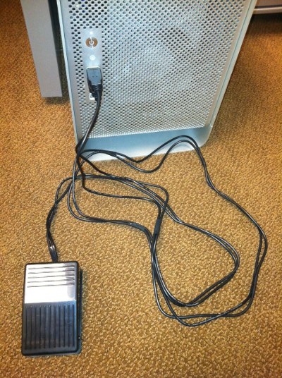
"The Vim Clutch": a footpedal for the code-editor Vim
@mental ruin I thought about g series but I don't have much room anyway
mental ruin
oh man, bind that to escape
echo hedge
😃
mental ruin
actually at this point my hand would still instinctively reach for it on the keyboard 😐
weary sentinel
@mental ruin Sorry, late to the game. You wouldn't believe how many times I've had to delete ":w" from a Word document....
 pastel iris
sputters
th... the whole point of vim is to reduce the amount of movement to do tasks!
adding a bass drum is the opposite of that!
(although it's pretty metal)
mental ruin
@echo hedge lots of cool stuff here:
https://github.com/googlecreativelab/open-nsynth-super/tree/master/pcb_hardware

GitHub
open-nsynth-super - Open NSynth Super is an experimental physical interface for the NSynth algorithm
echo hedge
I've used oshpark enough to see $$$$$$ when seeing pcbs that large
mental ruin
yea, I know
fickle leaf
Is it time to lobby for an Adafruit character related to music, like Synthy? Maybe just a new internal music routine for AdaBot? 😉
fossil shale
how about "Wavey"? then, depending on his mood he can be one of the following: sine, square, sawtooth...
 slate mauve
This ^^^
fossil shale
wait a sec... while "Wavey" could technically encompass all of it, how about "The CircuitPlayground Band"? although, that might get a little too outside of just electronics. "Introducing, Timbalina!" 😄
fickle leaf
Perhaps Blinka could be trained to form into wave shapes.  〰🔺 ◾ 👋
 lucid anchor
@fickle leaf Trained? You mean convinced.
 civic cliff
Wooed, even 😛
echo hedge
anyone know if there is a standard control voltage for A440?
 dusky whale
@echo hedge ...it depends... https://www.gearslutz.com/board/electronic-music-instruments-and-electronic-music-production/908904-analog-cv-control-voltage-standards.html

Hi,
does anybody know if there are any standards when it comes to control voltages (VC)?
...
echo hedge
yeah, I'm fine with mimicking eurorack at 0-5v but don't know what frequency range that covers
I suppose I could look at a keyboard...
dusky whale
output to a guitar tuner and tweak the knobs
echo hedge
I'm working on circuitpython audio stuff
and am thinking of having an object to convert frequency to "voltage"
looks at shruthi midi code
random bone
@echo hedge I think the osc is tunable and not fixed initially, but 1v/octave is usually how it varies. 5v only gives 5 octaves which is less than a piano.
so 0v might be any frequency, but 1v would be 2*freq
random bone
if you just look at at a typical vco control panel, there's a "freq" knob,
echo hedge
ah, then the control voltage adjusts it
dusky whale
You can tune a piano but you can't tunafish.
echo hedge
ah! ```c
// Used for MIDI -> oscillator increment conversion.
static const int16_t kLowestNote = 0 * 128;
static const int16_t kHighestNote = 128 * 128;
static const int16_t kOctave = 12 * 128;
static const int16_t kPitchTableStart = 116 * 128;
@echo hedge the freq knob sets a reference and the control voltage varies from that reference, 1v/octtave. MIDI messages can choose between 128 notes, which is > the 5-octave range of 0-5v. Looking at a typical (?) MIDI-to-CV manual: http://doepfer.de/a100_man/A190_2_man.pdf. This VCO module converts MIDI notes to a CV of 0-5 volts. It has a "learn" mode where you set the starting note number for 0V: See page 8. Note 1. Notes outside the range are ignored.
echo hedge
ah, makes sense
random bone
I learned about MIDI years ago but it was strictly for digital synths.
echo hedge
the shruthi is a hybrid so I'd love to come up with a system that works for both
random bone
does the shruthi have programmable calibration for the VCO(s)?
random bone
I think you should have a talk with CScott, since we are guessing at intentions and conventions. shruthi says it has a -24 to +24 semitone (aka note value) range in several places for the VCO's.
echo hedge
yeah, I'm in a rabbit hole but I'd love to rework what we have now (file playback and buffer playback (loop optional)) better organized
so we can play a file back to I2S instead of DAC for example
random bone
@echo hedge so can we just make a stream API that plays raw audio or mp3 audio or ..., and the stream devices all have the same calls, more or less. Maybe emulate some subset of https://docs.python.org/3/library/mm.html
echo hedge
yup, thats what my brain is chewing on
random bone
audio support is way different than audio synth and midi support
echo hedge
you don't need the control bits necessarily but chaining stuff would be nice
people have asked about volume for example
random bone
then maybe you are reinventing alsa or whatever
echo hedge
yeah, I've been looking at stuff
paul's audio library is interesting but static

shruthi code is here: https://github.com/pichenettes/shruthi-1/tree/master/shruthi
GitHub
shruthi-1 - Firmware and hardware description files for the Shruthi-1, an hybrid monosynth
random bone
so you want to say, send midi to shruthi, get PCM audio data back, and send it somewhere else? not sure there's any unified example of an API for that. looking around, gstreamer might be a model for routing audio. It doesn't support MP3 now but now that it's not patent-encumbered perhaps it could be extended. There are Python bindings for it
echo hedge
well, the shruthi code takes midi in
random bone
and there's analog waveforms out, which we have to ADC to get digital data back
echo hedge
I have a shruthi filter module which has one audio input and three control voltage inputs
random bone
I would just say I don't see unifying that with ordinary wav or mp3 playback or recording. pretty separate domains
echo hedge
why not? isn't a file or buffer just a sound source or sync like a ADC or DAC?
random bone
i mean unifying the shruthi control "API" with sound source/sink
echo hedge
ah
random bone
i do agree that files/buffers/adc/dacs are all sources/sinks of digital audio, and so something like gstreamer lets you pipe that stuff around. for the sources/sinks, there's ossaudiodev: https://docs.python.org/3/library/ossaudiodev.html
echo hedge
isn't oss pre-alsa?
random bone
yeah, I'm just looking for what's "typically" used in Python. I think there is no typical - many solutions here https://wiki.python.org/moin/Audio/ and I don't recognize one as the "standard" way of doing audio in Python.
echo hedge
yup yup, I was looking too
my current "ideal" is something like: kbd = audioio.Keyboard() osc = audioio.Oscillator(frequency=kbd.control_voltage, shape=SAW) dac = analogio.AnalogOut(board.A0) dac.value = osc.output time.sleep() dac.value = None
random bone
I'd put that functiality in a synth library. I'd put audio record/playback/piping in an audioio library. Doesn't mean the synth library can't use audioio, but I don't see them belonging in the same library necessarily
echo hedge
yeah, I agree. audioio would have the basics and synth can do the complicated stuff
random bone
random bone
lookint at pyo: very recent github checkins
echo hedge
pyo scared me off by having a "server" and presumed output
fickle leaf
you may have already considered that MIDI, WAV, and CV are streams that need to feed to/from audioio and synth modules equally. The synth library could be used like guitar pedals to shape sounds from any source, not just its own oscillators, for example. Is that what you have in mind?
echo hedge
@fickle leaf yeah, ideally
fickle leaf
cool.
echo hedge
Python's io is kinda nice until you realize its all file based: https://docs.python.org/3/library/io.html
k, lunch time
graceful apex
@echo hedge Yeah, Olivier is great open-source contributer: once a module breaks even in commercial sales, he creates a repo for it. Side note: Braids has been retired to be replaced by his new Plaits module. We'll probably see a repo for that in a month or so.
echo hedge
@graceful apex thats a great way to do it!
 pure turtle
: Hey all, I'm trying to find a pragmatic way to connect 50+ miniature speaker cones sculpture and be able to control channel distribution to all speakers individually through Arduino/MaxMSP. Can't seem to find any resources on largescale multi-channel tiny speaker rigging with Arduino. [talking 2w 50mm size speakers] Has anyone got any advise? resources? experience? they could help me with. Would be much appreciated 🙂
slate mauve
I'm assuming you would need sheilds and a full size breadboard. Im Not too experienced but I don't feel like a Arduino would have enough digital/analog ports to support 50+ output devices. Feel free to correct me if I'm wrong.
pure turtle
so an STM and a LattePanda? Possibly? @empty spear @slate mauve
presumably I'd still need amps [like PAM8403 or something]
the plan was to run Max on the Panda [to avoid a laptop rigged up in the installation]
but I could just make that talk to the Pi
I'm just unsure on powering the speakers and routing
the speakers will just be these guys: https://uk.rs-online.com/web/p/miniature-speakers/7755031/
echo hedge
@graceful apex what is the minimum functionality you need for the module playground? I2SOut? I'm trying to reign in my audio rework and do the minimum we need now
graceful apex
@echo hedge i2s would be ideal, but even SPI dacs are ok. It is just parts like the CS4334 have a lot of useful built-in features to take advanatage of.
echo hedge
@graceful apex i2s should be pretty easy to add. Is the buffer loop playback enough too?
graceful apex
@echo hedge probably
dull basalt
Hello, im looking for some help with a project that i want to start work at. Its the banana piano and drums i want to make it on 2 raspberrie pi with the touch HAT, if someone got experience with it, please direct message me, i can offer some kind reward in form of btc for the one that is kind enought to help :) thanks
dull basalt
I had very good results using Audacity and an Astatic 1104c communications desk microphone. I was able to bridge both L and R channels together on the input circuit to the desktop PC mic input jack, without issue -- sounded great.
Using Audacity, it's quite straightforward to check for proper mic level, to prevent constant clipping from occurring during an online conversation (as in Discord chat function).
 stable fulcrum
Hey everyone
I need some help
I wanna add two electret microphones to my lightblue bean
I have all the parts
But no idea what to do hardware or software wise
 sour cape
dull basalt
sour cape
dull basalt
I'm in the middle of my first point to point Hi-Fi tube amp SE stereo build, and now understand why PCB's are used...
mental ruin
You could always cut your losses and work up a pcb. In all honesty it's not that hard
 modern swan
OK, have a little question about SDR.
OK I can go to http://websdr.org/ get some morse code audio. Is there any program to use an audio file and get text?
Maybe on a Pi

GitHub
morse-code-virtual-radio - Learn morse code for the centenary of World War I
 tardy jetty
@modern swan in general, you would use an audio pipe program to redirect the audio output of your SDR tuning software, such as GQRX to be the input to a morse-to-text program.

Over on YouTube user Brent Crier has uploaded a tutorial video showing how to set up CWSkimmer with an RTL-SDR and HDSDR. CWSkimmer is regarded as one of the best pieces of software that can be used to decode CW a.k.a Morse code. Morse code i...
 small osprey
have anyone do a audio file convertion?
modern swan
@tardy jetty thank you for the information
 marsh pendant
Hey. I'm writing some circuit python for my trinket M0 and I'd like send audio output to a speaker. I was searching around and saw a nice tutorial for the circuit playground express that uses the audioio library to interact with it's speaker, but I can't seem to find audioio for use outside of the express.
My questions are: is the audioio library only for the playground? If so, what would be the best way of sending tones to my speaker a la the tone() function for arduino C?
And: is there a good tutorial on how to play tones in circuit python aside from the one written specifically for the playground?
fossil shale
@marsh pendant the audioio module isn't built with the non-express firmware. It may be possible to build your own with it enabled, but RAM space would be minimal at best (if it even builds). Here is the list of module support for 2.x firmware: < http://circuitpython.readthedocs.io/en/2.x/shared-bindings/index.html>
 astral wigeon
owo
 red rain
Hello o/ I found this :
https://www.youtube.com/watch?v=oHnRsi3saXI&feature=youtu.be
any clue if it would work on a raspberry ?
 dusty gyro
@red rain "Context works on Windows and Linux. " so it might!
red rain
🤔 ty
 flat beacon
hello
mental ruin
hello!
dull basalt
I believe you!
red rain
what kind of board would one use for best PureData music performance ? Also considering a price around 50€. is the new Raspberry 3 a good choice, for like a personal "Organell" emulator ?
organell is just an example though, I'd build my own craziness xD Tag me in your answer plz TY ^^ 
 white nexus
Hi new friends. I screwed up and bought the PAM8302A instead of the MAX98357 to add audio to a PiGRRL Zero. Anyone know if that will still work or if I hold off on assembly and order the right board?
I have no capacitors and the only resistors I have a 470 and 4.7k so I can't really do the filtering manually
red rain
Hello! Question, is it possible for Max Msp to read an XML data file, with arrays of numbers, and sonify it ? Or is it possible with Pure Data to, with the purposes of running that in a Raspberry ? I'd really appreciate any help or leads! Thank You !!!
 solar nest
if you wanted to create a small project that played back a fixed sample (i.e. the sample can be stored in flash memory or something, but doesn't have to change after initial load) when triggered, and wanted to be able to change sample rate in real-time with a pot, how would you approach this?
I'm looking to make a very simple digital drum machine (think a LinnDrum), and there are a lot of wav trigger boards out there, but no currently-made boards that I see besides the Tsunami Super WAV seem to allow real-time sample rate adjustment. I'm sure I'm missing some though, but I definitely don't have a problem with Arduino or putting together something more piecemeal. Also, for what it's worth, hi-fi is definitely not a concern for me at all as long as it's >10bit.
Oh, to add, I would prefer an option that is relatively cheap, or would allow multiple voices with independent outputs, as I'm aiming for 6 voices
I appreciate any help!
dusky whale
@solar nest Hi Ben, I just wanted to see what you refer to as changing the sample rate. My understanding is that a wav sound is encoded at whatever the recording rate was and I don't see any re-encoding feature on that Tsunami Super Wav board by Sparkfun.
solar nest
@dusky whale Thanks for the response! I'm referring to what one might call the "playback sample rate." The Adafruit Wave Shield can actually do this ( https://blog.adafruit.com/2008/05/21/wave-shield-bending-the-playback-sample-rate/ ), but its polyphony limitations + the cost to get more voices (one Wave Shield + one old Arduino per voice) mean it's not a great option for me. Each channel in the Tsunami can have its sample rate changed similarly (look for "OUTPUT_SAMPLERATE_OFFSET" here: https://robertsonics.com/tsunami-user-guide/ ). In both cases, reducing the sample rate would reduce the pitch (in what Robertsonics describes as "varispeed" control). This is how a lot of the early digital drum machines handled tuning.

Adafruit Industries - Makers, hackers, artists, designers and engineers!
Arduino wave shield – speed up – slow down demo from adafruit industries on Vimeo. One of the reasons I made the Wave Shield kit is that I wanted to be able to play with audio clips and…
dusky whale
@solar nest Thanks for the explanation. I guess I know that process as pitch correction which also ties into making other digital electronic effects. The Adafruit Audio FX board would be something to use to generate one-shot effects but you could gang up multiples to be controlled by one arduino microcontroller board. The Tsunami has a way more powerful controller chip and thus it can act like a mini-computer to be able to do all those features on that board. It does pack in a lot compared to making it piecemeal from separate components. There seems to be a lot of drum machine apps or software out there already that might suit your needs. But if you were looking for a hardware challenge, there are some MIDI drum controller/sequencer projects on the Adafruit site in the Learn or tutorial section. Good luck.
solar nest
@dusky whale Thanks for the answer! Yeah, I might end up going that way, though at this point I'm really preferring the sound of adjusting the sample rate -- it is a really distinct sound that sounds great on drums (just ask Prince haha).
The Adafruit Audio FX looks interesting, and the idea of having multiple boards like that controlled by an Arduino works for me (I was planning something like this for MIDI anyway), though it appears that you can't change the sample rate or the pitch with that board directly (https://forums.adafruit.com/viewtopic.php?f=1&t=81204). I know there are ways to change the pitch via DSP with another microcontroller, but I'm not sure I'd be able to get a good enough sound quality (my experimentation with that with Arduino a little while back seemed to suggest I won't, though I know there are some projects out there that combine an Arduino with an external memory chip to get good pitchshifting results).
Really, the Wave Shield is exactly what I want (see: https://vimeo.com/1039330 ), but I was hoping for something that would be less costly considering the # I'd need to buy (and # of old Arduinos I'd need to buy)
Maybe the Tsunami will be the way to go though!
Thanks for all the help!

Arduino wave shield - speed up - slow down demo
solar nest
I might go with Teensy + Teensy Audio Library and use its Wavetable object, tying the playback frequency to a pot (e.g. https://youtu.be/5laaNHLhS98?t=1m22s )... not quite the same, but I think it will sound good and give me the flexibility I want
The main thing I have to figure out is having multiple outputs. I know I can get two mono outputs from one Teensy Audio shield & board, so I suppose I could buy two sets for four voices, having each Teensy board be dedicated to two voices., each with their own audio out. This would be more expensive than getting the same amount of outputs as the Tsunami, but it'd allow me to do some digital FX and such right on the Teensy boards, and maybe some LFOs and such... I think I'll buy one Teensy + Audio shield set and go from there
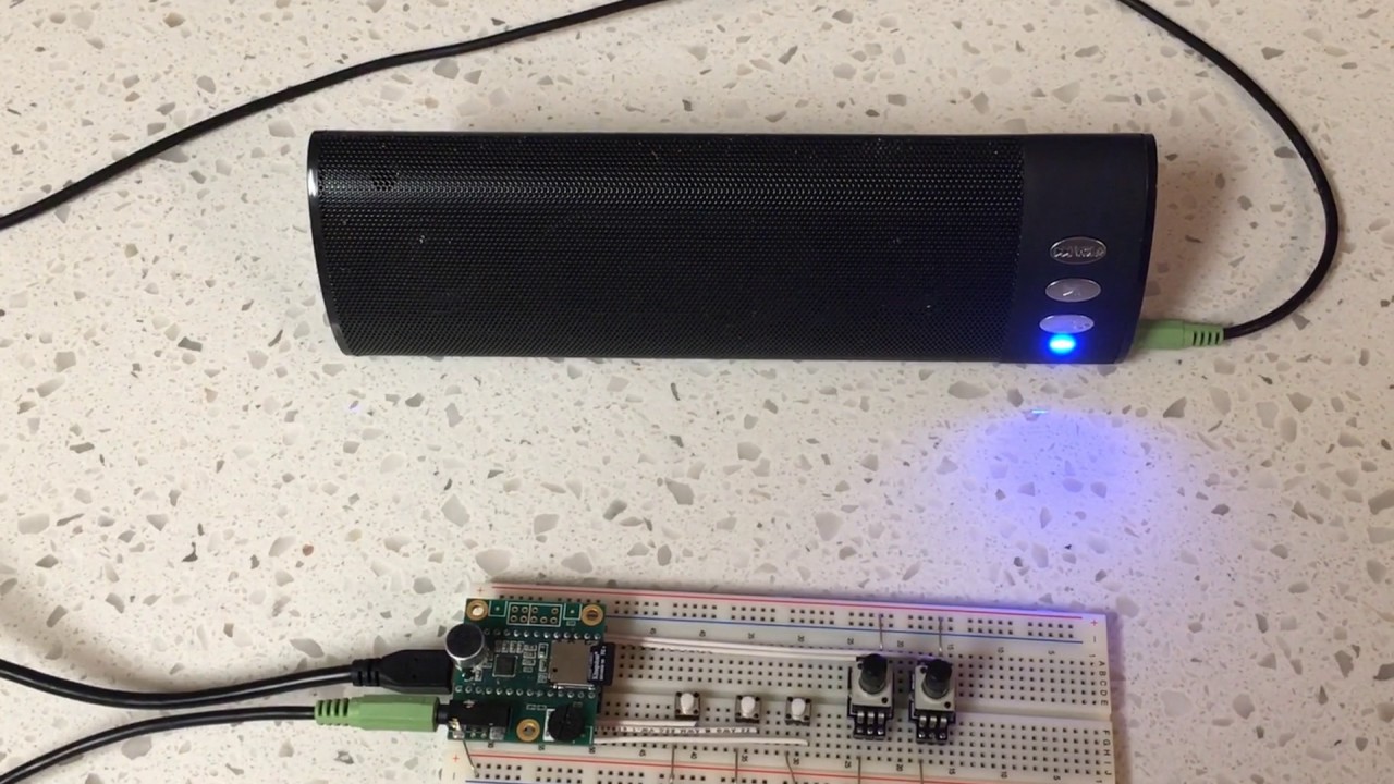
Here is a simple tutorial video showing how to get started in using the new Teensy Audio Wavetable object for sample-based audio synthesis on a Teensy microc...
 coral dock
Heya, being the Feather M0 has an actual DAC onboard, is there a possibility I could get actual sine wave tones out of it as opposed to the square waves that tone() provides?
dull basalt
I've forgotten how that's done, but may involve an external analog circuit.
Someone just mentioned 'wave function' like three days back.
coral dock
Hmm... I need to make a small mixer anyway because I have two audio sources (the Feather and a microphone input) so maybe I can integrate into that
dull basalt
I'm pretty sure you can 'integrate' (if that's the right word) something or other and get a sine wave from a square wave generator. I know it's about harmonic frequencies or similar (sine being entirely absent of harmonic energy).
If we do have something already I'd bet it's with the new SAMD51 M4 MCU.
My guess is there are algorithms one can use to generate input suitable to a DAC but I don't have specifics.
coral dock
Yeah no I got that, but I more meant because the feather apparently has a better DAC than like an Uno if it could make something more closely resembling a sine wave "natively" so to speak
Otherwise I think you guys do have something similar but if I can get rid of an extra board it saves on weight and space (it's going on a balloon)
dull basalt
Pretty sure operational amplifiers can generate waveforms. In that instance I think the sine wave is the more derived product. I just don't remember anymore.
This is all from analog music synthesis theory btw. ;)
@graceful apex is an expert.
coral dock
Thanks for the info :) I don't know much in terms of audio theory sadly, just a general idea of what I want and enough knowledge to be dangerous
coral dock
Thanks!
dull basalt
You're welcome. That one is a Forest Mims (alike) approach which I've always liked. Simple stuff you can cobble together in an evening or three. ;)
echo hedge
@coral dock I know you can do it with CircuitPython. I don't know how with arduino though. https://circuitpython.readthedocs.io/en/2.x/shared-bindings/audioio/AudioOut.html
dull basalt
Almost done with my first point to point tube amplifier.
Top side of amp.
It's been rough, new to electronics and DIY.
It all started when I picked up a book on Basic Physics 3 years ago, which lead to Make: Electronics and lots there-after..
fickle leaf
@dull basalt That's superb! The terminal strips, sockets, and point-to-point wiring are appropriately retro. Nice work!
dull basalt
Yeah you got some good-sized tubes in there, too. Octal based tubes are nice.
We trained on tubes in high school (mid 1970's) then didn't get to use them in the field very much. LSI (large scale integration) was already happening.
graceful apex
ANd here I thought I was among the last generation to work with tubes. 😉
dusky whale
I had to make my own tubes. https://www.instructables.com/id/Giant-Electronic-Vacuum-Tube/

Instructables.com
Happiness is a warm...vacuum tube?Harken back to the days of yesteryear, when people huddled around the old radio or black and white television for entertainment. ...
dull basalt
Hopefully it sounds better than it looks. Next up will be pre-amp's and recording equipment.
That tube lamp is a neat idea for a recording studio! Some day I hope to make some as shown in youtube videos like this: https://www.youtube.com/watch?v=EzyXMEpq4qw

YouTube
This wonderful video shows Claude Paillard, a French radio amateur (F2FO), making his own vacuum tubes (or thermionic valves). Just sit back and watch this d...
 quick storm
Not sure if this is the correct channel... I'm pretty new at this and wanted to find out how to make an MP3 player or music library. I'm not interested in streaming or online connectivity. Does anyone know a good project plan or guide for something like this? I tried looking and found mostly streaming or radio.
fossil shale
@quick storm here are a couple learn guides for non-streaming players:
https://learn.adafruit.com/mp3-feather-gordon-cole?view=all
https://learn.adafruit.com/minty-mp3?view=all
neither has a display, so you'll have to pull from other sources if that is a feature you want.
quick storm
Thanks a lot!
dull basalt
Adafruit did an MP3 player maybe even before the current web site was begun.
Could be obsolete. But still useful, to model an up-to-date solution (lets you know some of the possibilities).
 novel elk
@dull basalt Looks extremely obsolete. Last updated 2015, published 2013. The WayBack Machine's earliest snapshot is from 2005.
dull basalt
I don't remember when I became aware of Limor's web but it was pretty long ago.
x0xb0x on archive.org goes back to 2005.
novel elk
February 22, 2005 is the earliest anything on the site is archived back to.
dull basalt
Roit.
novel elk
"The site" being ladyada.net
dull basalt
agreed.
;)
cite: x0xb0x is available as a kit that includes all parts necessary to build a x0xbox: PCB, case with CNC machined faceplate, components, buttons and knobs, AC adaptor, pre-programmed microcontroller, and (of course) poorly xeroxed assembly manual...You supply the sweat & tears.
For the initial run of x0xb0x, we will make 100 kits. All of the components in the kit are through-hole. Kits will be available in March 2005 and will cost ~$300.
For more information about x0xb0x, or to be put on the waiting list for kits, email: &c.
I thought SpokePOV was earlier than x0xb0x.
That's the one that caught my full attention, but I think there were other reasons to visit there. Tech tips, parts procurement info &c.
graceful apex
The fake/counterfeit parts coming across the Pacific these days have even reached the transistors: the 2SC2291s I see on futurlec and such are all fakes. I would just use my usual matched pair flavors and (if needed) a little rebiasing. Anything can be fixed in transistorland with biasing. 😉
 harsh jacinth
@graceful apex i used 2xbc337a as a "drop in replacement"... provided you make a small adapter board.
no rebiasing necessary, 0 audible difference to my ears.

Another comparision of the "magical" and "rare" 2sc2291 Transistor in the TB303/x0xb0x against a jelly bean 2xbc337a. Beats me, I don't hear a difference.
Recorded at 50% cutoff and [100,75,50,25,0]
originally it was a makeshift installation (yes, got a fake one too the first time). After comparing both variants, i dont even remember whats inside my x0x currently.
fickle leaf
A DSP-G1 -based synth on a Trinket-sized custom PCB racing after a Trinket M0 running CircuitPython. Plans are to create a small MIDI voice module with a few selectable synth presets and an expression slider or foot pedal. Inspired by @tardy jetty 's recent synth project: https://learn.adafruit.com/feather-trellis-dsp-g1-synthesizer?view=all

Build a 1980s-style synthesizer with DSP-G1 synth-on-a-chip, a Feather, and Trellis keypads and knobs for control!
Here it is in action, paired with the Trinket. This a data throughput test with the Trinket M0 and CircuitPython receiving the MIDI messages, decoding and displaying the MIDI data via the REPL, then retransmitting to the DSP-G1.
dull basalt
Note to self!
dusky whale
@dull basalt That sounded like a ping.
fossil shale
Catching up on AAE last night, and with "N is for Noise" and all the Crickit happenings, I had the thought for a mini Leslie amp project. After some minimal research before much needed rest, my only concern is the low range frequency, and adequetly driving it.
fickle leaf
@fossil shale Yes, the low-end horn is a challenge. I wonder if a Bose-like folded waveguide (circular?) with a small woofer driver might balance and spin better than the traditional design.
fossil shale
well, preliminary parts ordered (lucked out that Feather Crickits came in stock today). Both of the 3" speakers were out of stock though. I've got an old surround system I can scavenge though. I had forgotten/glanced over the crossover in the circuit. not sure how well i can mock one up, but we'll see. i mean, the initial plan is to use an Adafruit box, so... 😆
fickle leaf
This will be interesting, indeed. Keep us posted!
 harsh axle
Anyone have experience using a teensy and the teensy audio library to do audio output without the teensy audio board?
Figured id ask since its the audio channel
fossil shale
Finally carved out some time for the Little Leslie. The scavenged surround satellite turned out better than i expected. 3" 5.8ohm driver, a 1" tweeter (no resistance noted; metered @ 3.5), and included a crossover. The Feather Crickit's amp drove it surprisingly well. Starting a cabinet plan in Sketchup. I have some 1/4" & 3/8" baltic birch plywood collecting dust, so I plan on using that. Originally thought of using cardboard, but with structural and tonal requirements, I don't think that would work all that well.
dusky whale
@fossil shale Keeping an eye out on your project, may use it to kick this one up a notch... https://www.instructables.com/id/Leslie-Birchinator-Neopixel-Arduino-MIDI-Switch/

Instructables.com
It's the Leslie Birchinator. Acacia missed it, it may prove poplar, knock on wood... Ok, the switch case is most likely birch.If you have ever listened to the sound...
fossil shale
@dusky whale i dig that project! i should have noted earlier, that i don't play the organ or any keyed instruments (at least not with any proficiency or regularity). i know of the Leslie mostly from classic rock. the idea just sort bubbled up from nowhere while reading the specs on the Crickit. Motor+Sound is a logical conclusion. 😄
side note: i would say that is Red Oak. Based on the length of the "cathedral" type grain, and the large open pores. Birch and Poplar can have similar catherdraling (birch less so). Poplar is often used to mimic other woods because its grain is similar to many others, and can be stained to highlight different qualities.
dusky whale
@fossil shale In the future, someone will make the Dyson Fan Leslie Speaker cab. I don't play with any proficiency or regularity but I do like my old easy sheet music books and easy guitar tab books with the chord names. Woodworking is fun as dabbling in electronics.
fossil shale
Dyson Fan Leslie...that would be interesting. 🌬
fossil shale
Of course, the hard part to design/implementation is the upper horn. Not many people have DIY'd this apparently. Here is a very interesting take, which is amazingly "simple"... https://www.youtube.com/watch?v=T3Bv2cE_5Xo

New design with foot pedal speed control. Just the rotary here, no other effects. First a bit of guitar, then an 'organ' sound from a Korg Poly-800 with fast...
dusky whale
Steampunk Victrola Audio Spectrum Enhancing Device! Do it! The magic ingredient is found here: https://www.adafruit.com/category/223
Adafruit Industries, Unique & fun DIY electronics and kits : Slip Ring - Tools Gift Certificates Arduino Cables Sensors LEDs Books Breakout Boards Power EL Wire/Tape/Panel Components & Parts LCDs & Displays Wearables Prototyping Raspberry Pi Wireless Young Engineers 3D printi...
fossil shale
This is why i love shopping McMaster-Carr. Who knew there was such a thing as "Ceramic Hex Nuts" that have a max operating temperature of 3000F? 🔥
novel elk
Well @fossil shale, what do you use for YOUR spaceships?
dusky whale
@novel elk Well, I always keep a few extra rolls of this... https://www.amazon.com/3M-Performance-Nuclear-48-Millimeter-54-8-Meter/dp/B000NG3ZKI
 main linden
Is there a list or other resource of musicmaker featherwing friendly online streams? I know it's really just any mp3 stream, but I was curious if anyone had collected a bunch of them in one place.
 urban sun
Hey everyone, for the sound fx board, how do i control the vol + through GPIO? Connect wires only or is there code needed?
fickle leaf
@urban sun Which sound FX board?
urban sun
Sound fx 16mb w/2.2amp..
I thought the amp would increase the volume significantly, i bought the 3W speaker set, they are not loud at all.
fickle leaf
Are you using it in stand-alone mode or UART mode with an MCU board?
I've used it both in stand alone mode and UART control mode (using Arduino code). First, check to see if your sound files are normalized to 0db (loudest possible). If that doesn't help, then try stepping up the volume using the Vol+ input (standalone) or through the UART from your MCU.
Haven't used CircuitPython with it myself. There may be others who have who can help with the UART volume-up command.
I used an external 2.1W amp with these speakers and achieved reasonable volume levels. Certainly not rock-n-roll levels, though. https://www.adafruit.com/product/1669

Listen up! This set of two 2.8" x 1.2" speakers are the perfect addition to any audio project where you need 4 ohm impedance and 3W or less of power. We particularly like these ...
urban sun
Thanks, it seems the 2.2w onboard amp is not enough to make it loud. I maxed out the vol on a 4 ohm 3W speakers and it doesnt sound loud at all.
glacial spruce
Maybe this amp? https://www.adafruit.com/product/1752

Pump up the volume with this 20W stereo amplifier! This slim little board has a class D amplifier onboard that can drive 2 channels of 4-8 ohm impedance speakers at 20W each. Power it with ...
Note that big speakers are more efficient (more volume for same wattage) than small speakers.
 tender radish
Impedance issues?
marsh pendant
Hmm, I have a similar question to the one above. I'm building a small project that I'd like to add some adjustable sound effects to. I'm still in the very early stages of planning and I'm very green to a lot of the concepts needed for creating an amplifier (e.g. see my question here https://electronics.stackexchange.com/questions/388920/understanding-how-an-audio-amplifying-circuit-works?noredirect=1#comment948795_388920).
Is there a good tutorial and cheap parts I can use to add sound to my project? I'm not needing to drive a big speaker system, I really just want to put a small speaker into a treasure chest so I can trigger sound effects when people get close to it.

Electrical Engineering Stack Exchange
I'm trying to learn electronics and electrical engineering through building small practical projects (toys mostly). I've been learning a ton from adafruit and spark fun, but I'm trying to branch ou...
also I'd like to to be battery powered so I don't know if something like this is too much or not: https://learn.adafruit.com/adafruit-20w-stereo-audio-amplifier-class-d-max9744

Blast your tunes with a high-efficiency class D amplifier
or would something like this be a better choice? https://www.adafruit.com/product/987

This incredibly small stereo amplifier is surprisingly powerful - able to deliver 2 x 3.7W channels into 3 ohm impedance speakers. Inside the miniature chip is a class D controller, able to ...
glacial spruce
I think the smaller 3.7W one would be sufficient unless it was going to be in a really noisy area.
marsh pendant
awesome. Yeah it won't be noise, I just want it to be a bit louder than a piezo speaker
thanks!
 jolly scarab
hello all, not sure where to post this, this is my first time here!
I have a guitar. I am planning on doing some major electronic upgrades in the near future. Pickups, push-pull DPDT potentiometers and wiring. I have 2 volume controls, and plan to use the push-pull feature on them to slpit the coils on the new humbucker pickups. I would love to use the tone push-pull potentiometer to activate a miniature built in amplifier in order to drive a pair of headphones plugged directly into the output jack of the guitar. would the Adafruit Mono 2.5W Class D Audio Amplifier - PAM8302 work for this project? keep in mind that a guitar produces very little electrical current, so would this amp even be able to hear the signal if it is not line level?
 vernal crag
Hey Folks! Been browsing around this channel for quit some time and thought i'd jump in. I'm an automation / privacy guy so always looking for hardware that's doing both. Have been using pi forever, now getting into more customization / software side. Would be cool to chat with some of you about it! Sorry if links aren't allowed, but just got this setup seeing if anyone has experience with it?
Trying to build onto the AI mesh network - thoughts?

Medium
by Alice Coucke, Michael Fester and Alaa Saade
 azure dune
@vernal crag Adafruit IO can PROBABLY integrate with SONOS, I dont have a system (I use an Echo with #help-with-wippersnapper-and-adafruitio ) if you're a privacy guy.
IFTTT->Sonos probably
vernal crag
@azure dune Oh nice! Thanks for looking out. I am definitely a privacy guy, hence kind of gearing towards hardware solutions with this built in. Was browsing on the Snips telegram for answers on this too yesterday http://t.me/snipsair
 azure dune
Hm, I don't know much about snips
 near summit
I am new to adafruit and arduino but I am trying to do a small project that would include using premade sound files and playing them randomly and at random times. I would like to be able to use a smaller speaker with this so that one one person could hear this at a time. If anyone would be able to help recommend what I should buy in terms of Arduino that would be very appreciated
glacial spruce
I built something like this a while back. The amplifier in the Wave shield isn't very powerful, but it works fine with a small speaker.
marsh pendant
morning (at least it's morning here). I'm running into an issue with the music maker wing. If the wing is plugged into my feather M0 and my feather plugged into my computer's USB port the serial port doesn't show when I try to select it. When I unplug, pull the wing off, and plug just the feather in I'm able to select the port just fine.
anyone run into this before?
I double checked all of my solder joints and none are touching each other. I also don't have the speaker hooked up yet, it's just the feather, the wing, and the SD card plugged into the wing
hmmm, ok I unplugged and plugged everything back in a couple of times and it's working now
¯_(ツ)_/¯
marsh pendant
is it possible to play a track with the music maker wing and perform other tasks at the same time? like if I wanted to play a sound effect and move a servo at the same time, is that possible?
I'm reading through the overview of the wing and I'm not seeing (or I'm missing) a description of if it's possible and, if so, how to do it: https://learn.adafruit.com/adafruit-music-maker-featherwing/play-music

Bumpin' tooonz for your Feather board
ah! I re-read the library reference: https://learn.adafruit.com/adafruit-music-maker-featherwing/library-reference
and now see the description of startPlayingFile:
boolean startPlayingFile(char *trackname) - Begin playing the specified file from the SD card using interrupt-driven playback. This allows your program to perform other tasks as the file is playing.
Bumpin' tooonz for your Feather board
 grave pumice
@marsh pendant I have a similar problem trying to use the Music Maker FeatherWing. I have created a menu driven (tft touchscreen project) and I am having trouble understanding how to use interrupts. Can you walk me through the useInterrupt function?
marsh pendant
@grave pumice so I don't know if this will help or not, but it's how I figured out what was going on. Basically,
- I read through the interrupt section of the page I linked above and noted each of the control pin locations
- I then figured out which IDE pins those locations used on the feather I was using (I'm using the M0 proto in this project)
- I then updated the pin assignments in the interrupt demo sketch to the appropriate IDE pin numbers
You can see the prototype sketch I'm working on here: https://github.com/chris-schmitz/treasure-chests/blob/master/prototypes/music-maker/music-maker.ino

GitHub
Contribute to chris-schmitz/treasure-chests development by creating an account on GitHub.
I'm def a newbie to programming microcontrollers and cpp in general, but the interrupts are working for me so I have to have done something right along the way ;P
there may be an easier way of getting to this result. If there is I'd love to hear it 👏
grave pumice
@marsh pendant, thanks for the reply. So, the attachInterrupt callout in your setup is how you assign what can interrupt the code? I am using the FeatherWing TFT with touchscreen. I need to research attachInterrrupt to see what parameters it has available.
marsh pendant
ah, yeah the attachinterrupts are where I'm adding hooks to the digital pins to fire the interrupt functions. AFAIK you can only do this on interrupt pins which should be noted in the pinout diagrams.
Here's the ref for attachInterrupt: https://www.arduino.cc/reference/en/language/functions/external-interrupts/attachinterrupt/
The Arduino programming language Reference, organized into Functions, Variable and Constant, and Structure keywords.
also, def read the About Interrupt Service Routines section where it says:
Generally, an ISR should be as short and fast as possible.
I ran into a snag on this sketch b/c at first I tried to fire the musicPlayer.setVolume() function in my isr functions and it caused odd behavior in the setup
and I had to refactor so that the ISR's just updated values that were then operated on in the loop
grave pumice
@marsh pendant, I am reading that now already. I still don't understand what I would assign the attachInterrupt to though. I am new to this stuff as well - learning by trial and error.
In my case, I want my MP3 Player screen to startup, begin a playlist and wait for touchscreen interaction. The approach I have been using thus far is essentially just using:
if (!ts.touched()) ...basically print the time and date to screen refreshing every minute ...
if (ts.touched()) ... if a certain button is pressed the do whatever (like volume up, volume down, next track, etc. ...
This works well when I am playing audio from a Si4703 basic breakout (just turn on and tune as desired). Then MP3 player has a lot more going on I guess and it requires using the interrupts. I just don't know what to assign them to.
grave pumice
@marsh pendant Here is my project on GitHub: https://github.com/rzelko/Clock-Radio-Project

GitHub
Adafruit Feather M0+TFT+MP3+WiFi Radio+Stereo. Contribute to rzelko/Clock-Radio-Project development by creating an account on GitHub.
dull basalt
dull basalt
^^ wrong approach. See #help-with-projects scrollback for mention of this, and a better approach.
fickle leaf
@crisp mirage tell me about that delay -- is it digital charge-pump?
used to be called charge-coupled-delay or CCD
 crisp mirage
I'm honestly not sure.
I've only heard it in action
and it sounds great
works on stereo, so that might have to do with it some
actually
I'm talking nonsense
it's not even stereo
I was definitely under that impression
taking a look at the actual insides
this is an application of it
but still, this isn't stereo
fickle leaf
Are there fixed delay taps?
crisp mirage
I don't think they are fixed
I'm seing a model that does have stereo out
fixing them wouldn't make sense
well, on the stereo one anyway
or maybe it's two tapped lins
I honestly don't know. Their documentation doesn't show the insides at all
they potted the thing pretty well
fickle leaf
The ones I found are affordable compared to a spring reverb. Looks like that model has three delay output taps.
crisp mirage
honestly, I'm glad I managed to even find these PT2399s.
They were cheap and seem reasonably easy to work with
and they're pretty versatile too
you can make both a reverb and a delay
oh and a chorus too
which is honestly already way more than what that accutronics IC can
sound quality and tone probably isn't better though.
fickle leaf
From what I've seen so far, the accutronics is likely an analog CCD device. The PT2399 has pretty low distortion specs, so they'll probably do the job. Their flexibility is fantastic.
fickle leaf
Yes, ADC --> memory --> DAC
dull basalt
You've managed to tap the inputs of a voltage divider (if you can even say that).
I don't know how to apply Thevenin's Theorem to that.
dull basalt
The taps on your audio mixer are on the inputs instead of the outputs.
fickle leaf
@crisp mirage -- dinner bell is ringing here, got to sign off. Let me know how it goes.
crisp mirage
Will do! Important ICs are gonna get here next week
but I can go grab the rest of them in person
Nis, I'm a layman and that's stretching it too. Do you mean to say that I'm sending the signal into the middle lead of the pots?
dull basalt
Well obviously you can wire a resistor network as you have, but I can't wrap my head around why you'd do it, except by a mirror-image error.
crisp mirage
I've seen a lot of circuits use them tat way and they work fine. If I understand anyway, the signal chooses to go either into the output, or to ground depending on the resistance of the pot
oh, why?
I don't know, actually
seemed like a good idea
dull basalt
The tap goes on the other side.
crisp mirage
¯_(ツ)_/¯
dull basalt
The way you have it now, you short the input to ground.
crisp mirage
if the pot is all the way to zero
well, no the other way
if it's maxed out
then yeah the input does short to ground
dull basalt
The way it's supposed to work is that you tap the output at some level above ground. If you tap it right at ground, it's the same as grounding the input /of the amplifier/.
What you did was ground the output /of the preamplifier/.
crisp mirage
I suppose that's a bad thing?
It's not been visible to me so far though
I've tested it on my phone, pc and various synths I've got around
dull basalt
No. Why deliberately short the output of a preamp to ground?
crisp mirage
Because I've no idea what I'm doing
haha
I thought that's how it's supposed to work since it's AC
dull basalt
It's okay to monkey see monkey do -- I don't have any issue with that. ;)
But have a plausible theory. ;)
crisp mirage
so I guess it should have a load before returing to ground
to avoid completely shorting itself
dull basalt
Tap the outputs not the inputs.
dull basalt
Post that schematic again.
 dull basalt
I'll try to do a quick screenshot of what I mean.
Now, a single input fed on the left is fed to four outputs on the right.
The key feature are the taps -- they tap the source.
The taps select a point in the voltage divider, somewhere above ground, to set the level of output.
Customarily, ground is at the bottom; the most positive voltage is at the top.
Input signal comes in from the left.
Output signal is fed to the right.
I wouldn't split one into four this way, but it was the quickest way to show the mirrored geometry of the overall situation.

Standard voltage divider circuit.
You used Vout as if it were V-in and I don't know what that's called (if anything).
dull basalt
I don't know the justification for that input scheme -- is it at all amplified or is it a pickup coil?
crisp mirage
it's off of a pickup coil
which is around the same voltage range I work with anyway
I guess this comment is why I stuck with them
dull basalt
That's probably designed so that when input and output are at the same potential, you hear the guitar loud; when they are far apart, the output presents a similar impedance to the next stage (The amplifier).
Would probably inhibit large level changes in other instruments plugged into other inputs.
wild guessing there.
dull basalt
Looks like that small guitar pot scheme depends on the fact that you're unamplified at that stage (it's just a coil; grounding it shunts no real power to earth and therefore melts nothing valuable).
That looks right but you drew it differently than I'm used to.
dull basalt
it's fine quick is good. ;)
I believe it's what I was referrring to, yes.
Each input 'develops' across the entire potentiometer's resistance.
crisp mirage
and doesn't short out to the preamp
dull basalt
You 'tap a portion of that energy, above ground' by moving the tap.
You can run that with amplified input, without shunting its energy directly to earth ground.
crisp mirage
when the tap is closed, the signal has to get through all the 10ks of the pot, so no chance of frying anything
okay, making a lot more sense now
dull basalt
The input barely 'sees' the load on the output.
The input sees the 10k pot as its load.
(always!)
crisp mirage
the sleeve is the earth
dull basalt
tip ring sleeve: tip is one channel; ring is another; sleeve is always earth.
dull basalt
afaik the telephone company invented tip-ring connectors.
Sleeve is the middle one so I have that wrong.
The 'ring' is the earthed one -- it's the mainbody.
The sleeve is the captured one between tip and ring.
crisp mirage
there we go
I'll fix it up tomorrow
though, I should probably put a light value resistor before the output
if I have all four channels maxed out
there'd be four times the current
I don't think that's good on whatever's taking the output in
speakers or headphones
anyway, thanks for the help nis. Genuinely appreciated
dull basalt
I got it wrong (again). Wikipedia calls the mainbody the sleeve and the captured ring the .. yes .. ring.
Ring is the right-hand channel's signal.
Tip is the left-hand signal.
I posted a better mixer the other day.
crisp mirage
when? I'd be able to look it up with the search bar
dull basalt
I'll look.
This guy explains in a lot of detail why the passive mixer will be too annoying to work with on a practical basis.
But he does show you how to do it, anyway. ;)
crisp mirage
I mean, I needed a literal mixer, for four channels so I could listen to all my korg volcas with a single pair of headphones
In the future, I do plan on using something active however
dull basalt
 crisp mirage
with proper stereo and so on
I see the taps now
starting to make a lot more sense
dull basalt
We had a guy wire up like 9 scanning radios to a single output audio amp.
at the time I didn't ask him exactly how he was doing it.
crisp mirage
why is this resistor here?
dull basalt
But he was basically dealing with 8 ohm speaker outputs from nine scanning radios. ;)
He describes that in the text, I think. Should be feedback I think.
crisp mirage
indeed
feedback resistor
R4
okay, I might actually print this out
I've got some trouble reading on screens
dull basalt
Me too. I'm in my late 50's and vision is kind of impaired at less than 20 feet. ;)
crisp mirage
I'm turning 20 in a month.
though, I think it's just the contrast of screens that bothers me
dull basalt
Oh good you'll get to see what happens when an entire country is in abrogation of its responsibility towards that country -- first hand. ;)_
crisp mirage
besides, I like reading on paper more because I can scribble on it and so on
archive it, tear it
there's a lot more going on I don't know
dull basalt
I go with the Kindle for text (non-backlit electronic ink style monochrome screen).
crisp mirage
I'm italian, we've experienced something very similar to what the US is going through
the media fueling people that should not come to the govt
negative press is still press
exposure
so on
I'm sure you've heard of berlusconi
dull basalt
People are going to have to learn that voting has consequences, and they have not learned this (or have forgotten its meaning).
crisp mirage
the italian equivalent of.. you know
anyway, I don't think this is a place for politics, no matter how much I'd love to discuss this further
dull basalt
Of course not. ;)
crisp mirage
again, thanks for the insight. I'm off for the night
dull basalt
Very good. I just thought I'd mention it!
dull basalt
wow I just saw the wikipedia on your you know. wow. just .. wow. thanks!
uses simple serial steganography in a social textual context dotcom
Znlor abg dhvgr nf vagrerfgvat nf ebg13 vf, ohg..
https://www.rot13.com


 dull basalt
I remember that part number from earlier in the week
crisp mirage
yup. Been yapping about them all week
CMOS digital echo generator.
incredibly low noise
@fickle leaf remember that belton / accutronics reverb module?
apparently it's built around these chips
Circuit analysis of the PT2399, a CMOS echo/delay/reverb processor by Princeton Technology.
"This integrated circuit has also demonstrated that with a careful design and good tuning, could be a fantastic sounding solution. Many well-known effects like Belton/Accu-Tronics reverb module, Danelectro FAB-Echo, and the Rebote Delay use this chip as the core of the circuit."
fickle leaf
Oh -- the ADC --> memory --> DAC approach, not CCD. Nice.
 tribal jay
im having some issues with a small op amp project im working on. i have a 100mv p-p audio input going to my lm358 but my output seems to be saturated and just pushes straight to 4v.
fickle leaf
@tribal jay The op-amp circuit diagram looks okay. What does the voltage look like on the junction of R1 and R2? What happens to the output voltage when the input is grounded?
tribal jay
strange, the output stays saturated even with ground on the input. the voltage im getting at r1 and r2 isalmost perfectly 2.5V
fickle leaf
Sounds like wiring or the chip. Are you using a solderless breadboard?
fickle leaf
I'd check the power directly on the chip first. The ground pin may be open.
tribal jay
i just did a continuity check, it should be seeing ground on the correct pin
fickle leaf
You can check the other static DC voltages directly on the chip pins. That will tell you if the breadboard contacts are okay.
What DC voltages do you see directly on the pins when the input is grounded?
(pins 1, 2, 3, 4, 8)
tribal jay
Ok here's what I've got
Pin 1 out: 3.8v
Pin2 inv input: 1.9v
Pin3non inv input:2.5v
Pin4 -V: 0v
Pin 8 +V: 5v
That 1.9 looks bad
fickle leaf
Yes. It should be the same as pin 3 if the feedback resistor is doing its job. Have you tried moving the circuit to another area on the breadboard?
You can also try it with the chip's second op-amp.
tribal jay
I have not tried moving it. Just need a few minutes to rebuild and hook my scope to it. Ok if moving it doesn't work I'll change to the second one
fickle leaf
Yeah, just to make certain that it's the chip and not the wiring. I've seen breadboard contact strips fail from flexing and manufacturing alignment issues.
Ultimately, what are you making?
tribal jay
ok just moved it and no change, let me swap to opamp2.
basically a just some sound reactive lighting. im taking the input from my phone, amplifying it a tad and making the waveform positive then shoving that into a microcontroller for led control
fickle leaf
Cool. Arduino, CircuitPython, MakeCode?
fickle leaf
One more question: Are you counting the pins counterclockwise from the pin 1 index marker?
(don't know how experienced you are, sorry)
tribal jay
Sadly I won't have another chip to test until Wednesday. But I've got to say I don't think it was the chip. I was getting output the other day when I had it configured for non inverting input. No worries there no way for you to know, I'm a moderately experienced computer engineering student. I've built a bunch of digital circuits before, this is really the first time I've done anything with opamps outside of a classroom. But yes I checked the datasheet for my pinouts.
But just for a sanity check, pin 1 is top left pin 8 is top right, right?
fickle leaf
Yes, when the index mark is top left.
tribal jay
Ok just making sure I didn't lose my mind at some point haha
fickle leaf
Resistor values could also be an issue, especially the feedback and input resistors.
fickle leaf
What are the voltages when the input is open? You may just need an input coupling capacitor.
My mistake. For some reason I assumed there was one there -- then looked at the schematic again. 😬
tribal jay
With an open input my voltages drop to 2.5
A cap in series with the input or from the input to ground?
fickle leaf
Then the chip is okay and your circuit will work if you add a cap in series with the input resistor and the phone output.
Sorry about the initial misdirection. My bad.
tribal jay
How big of a cap would you guess? Since it's audio my input won't be very high frequency
I've got a 100uf electrolytic lying around or some ceramic disks at .1uf
fickle leaf
There's a formula for determining the high pass frequency, but 0.1uf should allow most audio to pass through.
tribal jay
Ok, let me give that a try
I'm seeing no change with the input being set to ground
Wait let me check something
fickle leaf
C = 1 / ( 2*pi * f * R )
That's how it should respond. The output should stay at the midpoint. The audio signal will be superimposed on that.
tribal jay
didnt know that was considered a swear. hot darn, its working
all positive voltage, perfect. thank you for the help
fickle leaf
The bot is very sensitive.
You're welcome. Would enjoy seeing your working project. Will you be sharing it on Show and Tell?
tribal jay
haha sure. i plan on doing some more documentation incase anyone wants to copy it.
fickle leaf
Excellent!
tribal jay
probably will be in a presentable state this week or next week
fickle leaf
I'll watch for it. Have fun!
 junior prairie
How would I go about making a 50dB turntable preamp? I tried a cmoy and it didn't cut it lol.
glacial spruce
Coming up with 50dB of gain isn't too tough. The trick is doing so while limiting noise, distortion, and oscillation.
junior prairie
yeah
fickle leaf
... and the necessary RIAA equalization curves. It's doable, though. Lots of example circuits out on the interwebs.
fickle leaf
Depends on your objectives/requirements. Just do a google or bing search on DIY phono preamp RIAA like https://www.bing.com/images/search?view=detailV2&ccid=EIDPzrvR&id=EE2FC0C9F404AC6E8B56DE864CBCE88B64B4071F&thid=OIP.EIDPzrvRmIPjbMvcvyWwRwHaD_&mediaurl=https%3A%2F%2F1.bp.blogspot.com%2F-R-9rEJYrkgg%2FU4oBfLxOpKI%2FAAAAAAAABDI%2FBZRhLhhH2mI%2Fs1600%2FRIAA%2BPreamp%2BSchematic.bmp&exph=864&expw=1600&q=diy+phono+preamp+riaa+schematic&simid=608038557088812805&selectedIndex=25&ajaxhist=0 I prefer to use one like this: https://www.sweetwater.com/store/detail/USBPhonoPPS--art-usb-phono-plus
 junior prairie
that looks like a usb audio interface
fickle leaf
Yup. With line outputs, too.
fickle leaf
It's designed to provide preamplification for phonograph cartridges and provide a standard line output in addition to feeding USB for recording.
I think that's +/-10db trim, not total amplification.
What's the outcome you're trying to achieve?
junior prairie
I'm trying to play records on my turntable without having to max out my receiver's volume and it still being quiet. Most things I use the receiver for sound good at around the -50dB volume setting so that's why I say 50dB amplification
I've read some people say it's important to have two opamps, one for a gain stage and one for an output stage or something. Do you know about this?
fickle leaf
Yes, but one would probably suffice for folks who don't have a trained audiophile ear. Most receivers / speaker amplifiers have sensitive enough line inputs to not load the preamp output.
The example I linked earlier has a voltage gain of 1000 with a single op-amp. Haven't built one, though, so I'm no expert.
junior prairie
I'm using cheap enough opamps that I wouldn't mind using 2
I started with a $10 OPA2132 in my cmoy and it sounds the same as a $1.50 NJM4556AD I had for another failed project so I'm using those from now on
fickle leaf
Good for you. If it works for your ears, there's no reason to spend more.
junior prairie
I think those that think they can hear a difference are delusional
 rancid hollow
Does anyone know what actually happens to a guitar pedal when you screw it up by getting the polarity wrong? I have a reverse polarity pedal from ages ago that I may have plugged in the wrong way and blown lol... stupid musician problems. wondering if I can just gut it and replace any bad parts and have it working fine again. I’m very comfortable soldering if need be. If anyone wants a look inside the particular pedal I can crack it open when I get home today
glacial spruce
Depends entirely on the design. Some pedals simply blow a fuse. Others you may have fried a few diodes/transistors/integrated circuits.
echo hedge
@graceful apex @fickle leaf can you send me any MIDI related cpy code you have?
starting usb midi today
fickle leaf
Excellent. I'll DM a GitHub link to an M0-based sniffer that incorporates the entire MIDI stack.
 vagrant zephyr
hello
Is it possible to have multiple midi outputs from an arduino uno.... from what im reading it only has one serial port and I need one per output
sorry if something is obvious, im pretty new
from what im reading i think i need an arduino mega
dusky whale
@vagrant zephyr What are you trying to control? Are your devices capable of changing the receiving MIDI channel and have THRU capability when cabled up to chain everything up to one arduino MIDI output?
graceful apex
@echo hedge there is my module playground cpy, https://github.com/cs80/module-playground-v1/blob/master/oc_midicv.py

GitHub
Old Crow's Module Playground 10HP Eurorack module using the Adafruit Feather M0/M4 and CircuitPython - cs80/module-playground-v1
rancid hollow
Just tried to use an esp8266 feather huzzah with the music maker featherwing w amp... we want to create an Adafruit IO toggle that will play audio files from the music maker. We got the basic tutorial code for the toggle working and the sample code for the music maker working, on their own. But we can’t figure out how to code it so that the toggle triggers a sound on the music maker, and we haven’t found any tutorials for exactly that. We tried multiple amalgamate codes but even if they compiled they would either keep resetting the feather or just do nothing at all. Help please D=
vagrant zephyr
@dusky whale I have a couple ditto 4x That I want to control. These both have MIDI thru so one output works there. I also want to control a drum machine that I also planned to make with an arduino. I did not plan on that having midi thru. So yes it would be possible to chain like arduino midi clock -> ditto -> ditto -> arduino drum machine. Maybe that is a possible solution. I kind of liked the idea of having multiple outputs in case I needed more in the future. I guess for me right now If I can get multiple midi output or split the output with out too much effort I would like to do that.
 sour ice
I've been trying to make a VU meter with a lot of LED and came across this project : https://youtu.be/5P1fNMrfxMo
Wondering if anyone have any schematics for cascading several LM3915.
And do someone know why he used in the video 5 LM3915 and 1 LM3916? The 3916 has a different scale from the 3915 and in this video it seems to light up the LEDs from 0dB to +6dB so I don't understand what is the interest of going whith this model instead of using 3915 all the way.

Selbstgebauter Spitzenpegelmesser mit 5x LM3915 + 1x LM3916 pro Kanal = insgesamt 120Leds. Selfmade peak program meter with 5x LM3915 + 1x LM3916 per channel...
fickle leaf
@sour ice According to DigiKey, it seems that the 3915 is obsolete. They still have the old data sheet that shows some simple two-chip cascading techniques. https://media.digikey.com/pdf/Data Sheets/Texas Instruments PDFs/LM3915.pdf
sour ice
@fickle leaf Thanks for the pdf. Would you think using an AVR or PIC microcontroller with a lot of shift registers to drive the LEDs would be a better solution? I hesitate between using this obsolete (but made for that task) chip, or go with a micro. Would an AtMega328p be capable of sampling, processing mesuring and displaying on a bar graph the dB level of two audio signal (stereo) in real-time or do I need an ARM chip?
fickle leaf
@sour ice You're welcome. Probably depends on what you need in terms of accuracy and responsiveness. The beauty of the 3915 is that it's truly real-time and the logarithmic step calibration is built-in. Here's an example of a mono circuit with a 32U4 and 144 NeoPixel LEDs, not calibrated logarithmically, but certainly responsive. I'd guess that it would be possible to replace the microphone with a line-level op-amp buffer circuit and modify the code to display actual VU level in db increments. If one works nicely for you, I'd suggest you simply make another for the second stereo channel. https://learn.adafruit.com/vu-meter-baseball-hat/overview

Sound sensitive NeoPixel cap
sour ice
@fickle leaf Ok thanks, I think I will go with the programmable solution if testing goes well, it is way more versatile and can offer a possibility to implement a "peak hold" display. I will try it out
echo hedge
any recommendations for mac programs that use midi controllers?
echo hedge
ok, garage band is too fun
mental ruin
reason has a free demo for the mac
echo hedge
does midi use variable message lengths with CIN 0 and 1? I'm thinking I might strip and add padding from usb midi so the api matches UART's API
 agile stirrup
thinking out loud: I'm planning on setting up a couple of 'rgb led appliances' in my living room. I want those appliances to also be able to react to music. In order to not having to a) connecting audio to all of these devices or b) putting microphones in all of them I was considering building a 'listening server' which sits at a convenient location doing all the audio recording and FFT work and then transmitting the resulting data to any RGB appliance that wants it. Any thoughts?
glacial spruce
Sounds doable. You could transmit the data in a variety of ways.
 mint sinew
Is there a way to tie the - line of two amplifiers together? I have a bluetooth speaker circuit that is normally connected to two independent speakers, I am trying to make work with a pair of headphones instead of two independent speakers.
fickle leaf
@mint sinew Do you have a wiring diagram or schematic you can share?
mint sinew
Um, I think I can draw one up. One moment. Actually I'll send you a picture of the board.
When I tied the two - leads together, the audio became choppy and it really did not work almost at all. I am trying to use a headphone jack off of the two speaker connections but I can't get it to work right. I was able to get it to work by tying one - lead to the headphone connector, and the I connected the L and R channels to the connector.
fickle leaf
Looks like a couple of class-D -like amplifiers. It's not likely that they would survive connected the - outputs to a common for the headphones.
mint sinew
Is there anyway to join the two?
fickle leaf
There are three options that come to mind: 1) two independent 1:1 transformers with the primary coils attached to each amp output. The secondary coils could then be configured with a common "ground".
- use a dual op-amp to buffer the analog input to the class-D amplifiers (assuming that the decoder chip provides a suitable unbalanced analog signal -- which it likely does). The op-amps then could easily drive the earphones.
mint sinew
Would the LM339N work?
fickle leaf
- hack the headphones to separate the common wire and drive each ear independently.
Yes, the LM339 has a nice low-impedance output and relatively high current.
mint sinew
Sweet. I just salvaged it today from an old alarm system circuit. Do you have any recommendations on how it needs to be wired up?
fickle leaf
Sure. Have you worked with op-amps before?
mint sinew
Not really.
fickle leaf
Ok. Do you have an oscilloscope to look at the input signal to the amplifiers?
mint sinew
Nope.
fickle leaf
That would be ideal, but we can always make some assumptions...
mint sinew
I would like to get one at some point, but they are quite expensive.
fickle leaf
Indeed. If you have a makerspace or library nearby, they may have one you could use.
Hang on -- drawing a schematic.
(one-half of the circuit shown)
If you need more volume, change the ratio of the two resistors attached to the op-amp's negative pin.
mint sinew
I will try this. Thank you so much for the help!
fickle leaf
Certainly! Hopefully you'll be able to find that analog signal. You could use this circuit to "sniff" for it, but be prepared for potentially ear-splitting digital noise.
mint sinew
Oh wait, so what do the two - lines off of the amps on the bluetooth board connect to in this circuit?
fickle leaf
This won't work with the speaker outputs. You need to find the unbalanced analog audio that feeds each amplifier.
mint sinew
That's okay, I might just stick with what I was doing before. I don't have all of the right parts, right now. Thanks again for the help though!
fickle leaf
If you want to pursue the op-amp angle, look up "differential op-amp circuits" or "instrumentation op-amp circuits." They can handle the isolated +/- outputs of the class-D amplifiers.
That type of circuit is significantly more complex, though. That's why I avoided using it as an example in this case.
mint sinew
Okay.
fickle leaf
@mint sinew BTW, you were exceptional helpful in #help-with-projects yesterday! It's wonderful to see the community work together like that. Thanks!
mint sinew
Thank you. I may not know everything, but I try my best. I love this community!
 sly rain
Hey guys, idk if this is the right place to ask,
i have a subwoofer connected to my PC by audio jack, but im working on making a VU meter using the audio jack output from the pc. So i want to know, can i put a splitter or something inbetween, so the audio still goes to my subwoofer?
glacial spruce
Should be fine: the VU meter shouldn't load down the signal appreciably.
sly rain
alrighty
i just opened a Audio jack cable, it has 3 cables inside, a blue one a red one and an orange one, i cant find a datasheet for it atm, does anyone know what wat is
glacial spruce
Unfortunately, many cables don't use standard colors.
glacial spruce
However, it's easy enough to find Y adapters and use those.
To figure out, you can make a continuity tester out of a light or beeper and a battery.
sly rain
what about, just a multimeter? 😛
glacial spruce
Oh, if you have a multimeter, that makes it much easier! If it has a "continuity" function, use that. If not, use the "ohms" setting.
sly rain
is it possible that every single strand of wire, is still insulated?
it looks like a see through plastic/rubber
glacial spruce
Probably. You probably need to strip off the inner insulation as well to test it.
If you're really unlucky, it's made of something known as "tinsel wire", which is difficult to connect to even when it's stripped.
sly rain
i cant even strip it, my cutter has no holes for this small
glacial spruce
Then you're stuck trying to strip it other ways. Things I've had some (but not a lot of) luck with are: scissors, wire cutters, nail cutters, knives, and melting it back with a flame or soldering iron.
sly rain
glacial spruce
That looks depressingly familiar.
sly rain
i just heated it up
and it melted
like
the wire is clean now 😛
TOP: Blue
MID: Red
BOT: Orange
thats how it goes
so orange is ground then, red is right and blue is left
glacial spruce
Cool, progress!
sly rain
yes! thanks! 😄 Now im gonna check if i can read the values on my arduino, and how to 😛
glacial spruce
Let me know how it goes!
sly rain
i will 😄
glacial spruce
Sweet!
sly rain
😄
 restive steeple
Would it be possible/feasible to use a circuit based on VS1053 to ADC and encode to OGG Vorbis then transmit data stream over an xbee mesh network where each node would decoded and then perform DSP before DAC to an amplifier pushing a speaker?
...or something else?
I've been very interested in miniDSP where I could add PEQ and delay to each speaker for $80 a pop https://www.minidsp.com/products/minidspkits/2-x-in-4-x-out
MiniDSP 2x4 kit, our low cost 2xIN, 4 OUT audio processing board for DIY audio applications. Great sound in a 3" package.
I've looked a lot at AudioCast a lot where the receivers are $30, but a transmitter that has DAC and encoding runs $180 (ieast stream pro)
sly rain
Hey guys, i have connected my audio jack cable to my Arduino, it as 3 cables, BLUE ORANGE and RED, where orange is GND,
But im getting like a static noise from BLUE, red works perfect, it reads from 0-300+ based on the music etc
but BLUE sticks at 1023
also when reading out the red one, it goes to 0 alot, while theres still sound being played
which makes my led flicker alot
glacial spruce
Yeah, the sound is an AC waveform, which goes through zero pretty often, so if you happen to read it at that point, you'll get 0. You might want to add a averager/peak detector circuit if you're just looking to measure the general level of sound.
sly rain
Is that like an actual circuit or is it just a piece of code? 😛
glacial spruce
It's an actual circuit, basically a diode, capacitor, and resistor.
restive steeple
Rectify and smooth!
dull basalt
basically a power supply ;)
sly rain
haah the power supply right now is my PC 😛
going to the arduino and to the led strip (the 5v output) haha
 light crag
What is different between A AB and d amplifierrs
light crag
That was helpful @dull basalt