#help-with-audio
1 messages · Page 4 of 1
 hearty knoll
 red sedge
as long as my -3db point is like 15hzish, its fine by me. just trying to figure out what exact cap i need to do this as I'm not sure what the impedance of the thing at the other end is. could be a phone, could be a laptop, whatever.
http://www.learningaboutelectronics.com/Articles/High-pass-filter-calculator.php#answer1
From here, a 0.1uf cap and 470k resistor gets me a 3hz -3db point but i have no clue if those values are sane?
 glacial spruce
red sedge
http://www.learningaboutelectronics.com/Articles/High-pass-filter-calculator.php...
glacial spruce
red sedge
http://www.learningaboutelectronics.com/Articles/High-pass-filter-calculator.php...
It depends on the load impedance. If you're driving any sort of load, those values are too small. For reference, an ordinary line level audio signal is typically loaded by 10kΩ or so. You can add a buffer op-amp after your shifter, or simply use an op-amp with a voltage bias as your shifter. If you don't want active circuitry, you're left with using a lower impedance design (which equates to a larger capacitor and resistor: how much larger again depends on your load impedance)
red sedge
I tried an opamp design but did not realize how brutally difficult it would be

Turns out there are many, many issues with this
I just want to hook it up to a laptop haha, had no clue it would be this brutally difficult
Spent 6+ hours on this yesterday and I'm basically giving up at this point bahaha
glacial spruce
@red sedge Oh, looks like you're trying to filter a PWM output into an analog output. You could simplify it by level shifting your 0-5V digital signals to -2.5 - +2.5V. Note that you still need a negative voltage supply (the op-amps would also need a negative supply to output a signal that goes below zero volts).
And yes, it's one of those things that's easy to describe but dauntingly complicated to actually implement.
You could reduce the capacitor values needed by moving the level shifting capacitors to the higher frequency PWM signal, then have a bias resistor and filter capacitor. Not too bad, three capacitors and three resistors.

 modest island
Question: I am using the RP2040 propmaker with a speaker that plays a sound sometimes.
When it's in "idle" and there is no sound playing for a few minutes I sometimes here a short loud "DOOT" (?)
Why is that happening? And how can I prevent it?
 dusty rivet
modest island
Question: I am using the RP2040 propmaker with a speaker that plays a sound some...
dusty rivet
modest island
Question: I am using the RP2040 propmaker with a speaker that plays a sound some...
Small fluctuations in voltage on the pins might cause small glitches
 weary gyro
modest island
Question: I am using the RP2040 propmaker with a speaker that plays a sound some...
weary gyro
modest island
Question: I am using the RP2040 propmaker with a speaker that plays a sound some...
Is your program changing the audio device in any way when it’s not playing sound?
weary gyro
modest island
Just mixer.voice[0].play(tracks[0]) and a few others
hmm. yeah that's weird. I assume this board is connected to your computer and has the CIRCUITPY drive? If so, it's probably your computer doing stuff to the CIRCUITPY drive. That will almost always cause glitching
modest island
It also happens on battery sometimes
weary gyro
modest island
It also happens on battery sometimes
okay so not CIRCUITPY then. Without seeing your whole code and your wiring, it's hard to diagnose further. Suffice to say, it's not supposed to do that. 🙂 You could try upping the buffer size in AudioMixer to see if that gets around it
 shut widget
hey guys, I'm building my first embedded project, it's a 12 note synthesizer. I'm using a raspberry Pi Pico connected to a mpr121 i2c touch pad and a max98357 i2s amplifier. is it possible to play a RawWave asynchronously? like taking input and playing it at the same time
 young pawn
shut widget
hey guys, I'm building my first embedded project, it's a 12 note synthesizer. I'...
young pawn
shut widget
hey guys, I'm building my first embedded project, it's a 12 note synthesizer. I'...
yes! Are you using arduino?
if so, just use the I2S library included in the arduino-pico core. It automatically and by default uses direct memory access (DMA). In fact, DMA can't even be disabled. So you can only play asynchronously! 😆
It works like this: When you put audio data into I2S to be played, it gets written to a buffer. That buffer is continuously played back using DMA.
There are blocking and non-blocking I2S write functions.
Blocking = try to write to the output buffer. If it's full, just wait. In this case your code has to handle the fact that the write function might take a few ms.
Non-blocking: Try to write to the output buffer. If it's full, just return. In this case your code has to handle the "write again a bit later when there is again space in the buffer" logic.
https://arduino-pico.readthedocs.io/en/latest/i2s.html
shut widget
ah, I'm using a RPI Pico H
young pawn
Asynchronous stuff is extremely important for audio. Whenever the output buffer runs empty, there can be audible clicks and pops. So it's important to make your code fast enough so the output buffer stays filled.
young pawn
shut widget
ah, I'm using a RPI Pico H
Arduino-Pico runs on pretty much all boards with RP2040
young pawn
If you're using circuitpython then I don't know. Actually, I would bet with 99,99% certainty that it also uses some asynchronous I2S output by default.
This is the relevant circuitpython thing: https://docs.circuitpython.org/en/latest/shared-bindings/audiobusio/index.html
shut widget
the code listed on adafruit website (https://learn.adafruit.com/mp3-playback-rp2040/pico-i2s-mp3)
# SPDX-FileCopyrightText: 2018 Kattni Rembor for Adafruit Industries
#
# SPDX-License-Identifier: MIT

"""
CircuitPython I2S Tone playback example.
Plays a tone for one second on, one
second off, in a loop.
"""
import time
import array
import math
import audiocore
import board
import audiobusio

audio = audiobusio.I2SOut(board.GP0, board.GP1, board.GP2)

tone_volume = 0.1  # Increase this to increase the volume of the tone.
frequency = 440  # Set this to the Hz of the tone you want to generate.
length = 8000 // frequency
sine_wave = array.array("h", [0] * length)
for i in range(length):
    sine_wave[i] = int((math.sin(math.pi * 2 * i / length)) * tone_volume * (2 ** 15 - 1))
sine_wave_sample = audiocore.RawSample(sine_wave)

while True:
    audio.play(sine_wave_sample, loop=True)
    time.sleep(1)
    audio.stop()
    time.sleep(1)
uses time.sleep
young pawn
ah yes circuitpython
shut widget
i might switch to the approach used here - https://learn.adafruit.com/multi-tasking-with-circuitpython/multiple-leds (example has blinking LEDs but i can modify it for audio playback)
young pawn
Tbh I really don't know a lot about circuitpython. Used it literally once. 😆
shut widget
shut widget
the code listed on adafruit website (https://learn.adafruit.com/mp3-playback-rp2...
also in the above code, I don't understand the for loop. what is it exactly doing? I told myself that it is calculating 8000 // 440 samples of A4 but why would number of samples differ across pitches?
shut widget
young pawn
Tbh I really don't know a lot about circuitpython. Used it literally once. 😆
ah fair 😭 , what do you use then?
young pawn
(2 ** 15 - 1) what is this ** syntax?
young pawn
shut widget
ah fair 😭 , what do you use then?
arduino
but to be completely honest, audio on arduino is kinda pain
shut widget
young pawn
`(2 ** 15 - 1)` what is this ** syntax?
2 ** 15 = 2 ^ 15 (raised to)
young pawn
Like, the I2S library included in the arduino-pico core is now as far as I know bug-free. but the higher-level feature rich audio libraries on top of it... I don't really like them.
young pawn
shut widget
2 ** 15 = 2 ^ 15 (raised to)
ahhh thanks
shut widget
young pawn
Like, the I2S library included in the arduino-pico core is now as far as I know ...
I see, I'll stick to circuitpython for now as I need to start with something
but eventually I see myself porting my codebase to either C or Rust
young pawn
I think: (keep in mind, I don't know python well, and I know circuitpython audio even less)
int((math.sin(math.pi * 2 * i / length)) just make a sine wave.
* tone_volume change the amplitude, because that's the volume
* (2 ** 15 - 1) not sure where that -1 comes from. But this could be basically a left-shift because the sine wave should be mono on only one channel.
weary gyro
young pawn
I think: (keep in mind, I don't know python well, and I know circuitpython audio...
2**15 - 1 = 32767. The -1 is so you don’t go over to 32768, which is too big for a signed 16-bit number
shut widget
I understand everything but the last multipication
why not just left shift it as << ?
weary gyro
“Why not just say 32767?” you may ask? That’s a good question and one reason is so you remember that it’s a signed 16-bit number. The other is just because sometimes people like to be clever 😀
young pawn
And why left-shift by 15 and not 16 bits?
weary gyro
Where are you seeing left shifts?
young pawn
I'm honestly just guessing that's why there's that multiplication with (2^15 -1)
something like 32bit integer = [16bits Left channel][16 bits right channel]
Then calculate some value (it's in the lower 16 bits), then left shift it so it moves into the higher 16 bits.
But maybe I'm assuming too much because that's how it is in arduino. And I'm suspicious of any 2^something multiplication to be actually a left shift 😆
shut widget
also is there a way in circuitpython to play audio in real time? rather than play a buffer for x seconds
basically every 1/sr seconds it plays a certain frequency and amplitude for the next 1/sr seconds
sr being the sampling rate
young pawn
you don't want audio to be "too real" real time, because there is an audible pop when the buffer runs dry.
So you want the buffer to be large enough that it doesn't run emtpy during the [read sensor value, then calculate next samples, then write those samples to the audio output buffer] loop
glacial spruce
Usually it's a level, not a frequency
weary gyro
I'm still not seeing any left shifts in the CircuitPython code. The "I2S Tone Playback" code is doing this:
- allocate buffer called
sine_waveholdinglengthnumber of signed 16-bit values (h) - fill that buffer with a sine wave from
math.sin()that is scaled to be in that signed 16-bit range, and also scaled down bytone_volume - have the audio output play that sample for one second
shut widget
weary gyro
I'm still not seeing any left shifts in the CircuitPython code. The "I2S Tone Pl...
but what is the "length = 8000 // frequency" line doing?
weary gyro
shut widget
but what is the "length = 8000 // frequency" line doing?
Ah. In Python // is integer divide. e.g. 30 / 7 = 4.2857.. and 30 // 7 = 4. That particular line is determining how long to make the buffer based on the sample rate (8000) and the frequency. And that length has to be an integer
shut widget
yes, I know. but why is the length differing across frequencies?
why would the number of samples differ across frequencies?
weary gyro
shut widget
yes, I know. but why is the length differing across frequencies?
because it's hard to arbitarily map waveforms of different frequencies to a fixed-length buffer, so instead the buffer size is changed so it always exactly one wavelength
shut widget
ahh I see, but then won't the duration of calculated samples also differ?
weary gyro
yes, exactly!
shut widget
wouldn't that be a pain if say I were playing the note for a longer or shorter time
young pawn
weary gyro
I'm still not seeing any left shifts in the CircuitPython code. The "I2S Tone Pl...
* (2 ** 15 - 1) so this is that "scale to be in signed 16 bit integer range" part, right?
weary gyro
shut widget
wouldn't that be a pain if say I were playing the note for a longer or shorter t...
yep, this is exactly what early sample-based musical instruments did
shut widget
so is there no way to, calculate only 0.2 seconds worth of the audio at a time?
if i choose my array size to be 8000 * 0.2
but I'm guessing that would cause the popping noise problem
glacial spruce
There are ways around that, but they tend to cause other problems
In the early days of computers, people would store their programs on audio cassettes. One popular standard was the "Kansas City Standard", which was designed to use a fixed number of cycles per interval, so a mark was 8 cycles of 2400Hz and a space was 4 cycles of 1200Hz. This was nice and even and easy to calculate, but in the audio realm it was a disaster, as one carrier was the second harmonic of the other one, so any distortion tended to make it hard to decode as the signals would easily bleed into each other.
weary gyro
shut widget
but I'm guessing that would cause the popping noise problem
yeah exactly. you want your waveform's start & end values to be the same (usually zero) to eliminate popping but it's hard to to that with a fixed sample rate and arbitrary waveform frequency
 quaint wave
Dumb question, I'm looking for a way to make my AKI Mini MK3 midi controller (https://www.amazon.com/Professional-Keyboard-Controller-Production-Software/dp/B0886ZPWC8/ref=sr_1_1?crid=IH1FFS07ZUDD&keywords=Akai%2BProfessional%2BMPK%2BMini%2BMK3&qid=1700953500&sprefix=akai%2Bprofessional%2Bmpk%2Bmini%2Bmk3%2Caps%2C244&sr=8-1&th=1) the "play" version of it? (https://www.amazon.com/Professional-Keyboard-Controller-Speaker-Software/dp/B09NQBDGT3/ref=sr_1_3?crid=IH1FFS07ZUDD&keywords=Akai%2BProfessional%2BMPK%2BMini%2BMK3&qid=1700953653&sprefix=akai%2Bprofessional%2Bmpk%2Bmini%2Bmk3%2Caps%2C244&sr=8-3&th=1)

AKAI Professional MPK Mini MK3 - 25 Key USB MIDI Keyboard Controller With 8 Backlit Drum Pads, 8 Knobs and Music Production Software Included

AKAI Professional MPK Mini Play MK3 - MIDI Keyboard Controller with Built in Speaker and Sounds Plus Dynamic Keybed, MPC Pads and Software Suite,Black
I need to get the Mini power and midi seperated from the USB. Then I though I could use my prop maker feather to generate the sound with synth IO
has anyone done anything like that?
weary gyro
quaint wave
Dumb question, I'm looking for a way to make my AKI Mini MK3 midi controller (ht...
The Akai Mini MK3 only does USB MIDI, and having a microcontroller act as a USB host is difficult (but not impossible). It would be a pretty advanced project in CircuitPython, if CircuitPython could be a USB MIDI host, which it cannot yet.
If you used a Teensy, their USB MIDI host functionality is more robust, and their Teensy Audio Library is a pretty nice way to design synthesizers in Arduino. But you’d still be a far cry away from all the functionality of the Mk3 Play.
quaint wave
thank you
weary gyro
But hopefully in a less than a year we’ll be able to plug USB MIDI controllers into CircuitPython boards and use them! This is something I’m very keen on seeing
quaint wave
Yeah me too
So until then I can get a USB MIDI Host to connect to my CircuitPython board to make sounds.
https://learn.adafruit.com/midi-for-makers/overview looks to be a good place to start


Adafruit Learning System
Build your own tiny-yet-powerful synthesizer
Thank you for your help and help on JP's guide. 😁
 echo hedge
weary gyro
But hopefully in a less than a year we’ll be able to plug USB MIDI controllers i...
echo hedge
weary gyro
But hopefully in a less than a year we’ll be able to plug USB MIDI controllers i...
I got mine working already. Have you tried it recently?
weary gyro
echo hedge
I got mine working already. Have you tried it recently?
I see no APIs for doing this in readthedocs. The usb_host module only has Port and set_user_keymap
echo hedge
weary gyro
I see no APIs for doing this in readthedocs. The `usb_host` module only has `Por...

GitHub
CircuitPython USB host driver for MIDI devices. Contribute to adafruit/Adafruit_CircuitPython_USB_Host_MIDI development by creating an account on GitHub.
looks like I haven't cleaned it up yet
The device API is under usb which is what pyusb provides in CPython
weary gyro
echo hedge
The device API is under `usb` which is what pyusb provides in CPython
Interesting! Thanks! How does one configure what kind of USB Host technique is being used? (e.g. reusing built-in USB vs RP2040 PIO)
echo hedge
RP2040 will only do PIO based USB host
because we want to leave the native USB for device
weary gyro
echo hedge
because we want to leave the native USB for device
How do I know which pins are being used? Or is that something I configure?
echo hedge
dp and dm are provided to usb_host.Port()
native USB will restrict it greatly. PIO just needs to be consecutive iirc
weary gyro
ahh so the example doesn't cover usb_host.Port() because it's for a different arch? https://github.com/adafruit/Adafruit_CircuitPython_USB_Host_MIDI/blob/main/examples/usb_host_midi_simpletest.py
I'll start playing with this presently and maybe submit a PR for RP2040 for that library. Thank you! this is so cool!
echo hedge
weary gyro
ahh so the example doesn't cover `usb_host.Port()` because it's for a different ...
Ya, I think I was testing on imx rt with dual usb ports. So the board has already defined and inited the host port.
weary gyro
echo hedge
Ya, I think I was testing on imx rt with dual usb ports. So the board has alread...
Hey this is pretty great. USB MIDI host seems to work well on both RP2040 Feather w/ USB Host (which already plumbs the usb_host.Port()) and on Pico
echo hedge
weary gyro
Hey this is pretty great. USB MIDI host seems to work well on both RP2040 Feathe...
I only tested it with my keystep midi controller
 near lily
Hi! I am working on a teensy project and using the audioshield for this project. i am trying to find the correct pin ID for one of pins that my wire is going to. I keep getting this error. Was wondering if anyone knows how to properly write this pin into my code
this is how I have it defined: #define PLAYBACK_BUTTON_PIN "HP_L"
let me know if you need the data sheet for the PCB i can also upload that.


 twin cedar
near lily
Hi! I am working on a teensy project and using the audioshield for this project....
twin cedar
near lily
Hi! I am working on a teensy project and using the audioshield for this project....
try without the quotes
near lily
C:\Users\aguir\Downloads\audio-guestbook-main\audio-guestbook-main\audio-guestbook\audio-guestbook.ino:40:29: error: 'HP_L' was not declared in this scope
40 | #define PLAYBACK_BUTTON_PIN HP_L
| ^~~~
this is the error that I get now
twin cedar
i am confused as to what you want can you share the rest of the code
near lily
yeah, how would u want me to share it?... send the file?
weary gyro
near lily
C:\Users\aguir\Downloads\audio-guestbook-main\audio-guestbook-main\audio-guestbo...
if that's supposed to be a pin number, it needs to evaluate to a number not a string. if HP_L is another #define just use it without the quotes
weary gyro
near lily
C:\Users\aguir\Downloads\audio-guestbook-main\audio-guestbook-main\audio-guestbo...
where is this "HP_L" coming from?
And if you're asking about a Teensy project, you may have better luck on the Teensy forums. Here's a post that seems to be about the code you're using https://forum.pjrc.com/index.php?threads/teensy-4-0-based-audio-guestbook.70553/
Teensy Forum
I built the project shown under this Youtube entry using a Teensy 4.0 and the 4.0 Audio card and a Sandisk Ultra 32 GB micro SD card; it sort of works but there are issues that I see have been experienced by others (towards the end of the comments under the video). The code implements the...
weary gyro
echo hedge
I only tested it with my keystep midi controller
I think I'm seeing some problems with a supervisor.reload() (or Ctrl-D) not resetting the USB Host stack making usb.core.find() not see the device. Does this sound possible? Is there something I can do to explicitly bonk it like displayio.release_displays()?
echo hedge
weary gyro
I think I'm seeing some problems with a supervisor.reload() (or Ctrl-D) not rese...
It isn’t meant to reset usb host on reload. Find should still work though. Please file an issue. I want to polish up usb host for 9
weary gyro
echo hedge
It isn’t meant to reset usb host on reload. Find should still work though. Pleas...
k. I'll make some test cases. Any issue with composite devices? I can only get CircuitPython USB MIDI devices occasionally to be recognized
echo hedge
weary gyro
k. I'll make some test cases. Any issue with composite devices? I can only get...
Not sure. Haven’t tried it
 shell nymph
Good morning! I've two adafruit FX soundboards, both the 16mb, one with the audio jack one without.
I need to set them up to run remotely when triggered; not very long range, maybe 5 feet at most. No sensors to trigger, just manual buttons. I saw the 315mhz kit adafruit sells, which is neat, but the keyfob style transmitter is a bit too cumbersome, and I don't have the time or tools to disassemble it. Any suggestions to overcome this hurdle? Or a different path? I see those cheap 433mhz TX/RX boards on the site that will not be named, but I get the impression there needs to be something extra to be added, and if that's the case perhaps there's something in the adafruit collection that would allow for this, that hasn't be introduced or updated recently.
circuit python or feather also works; don't need to trigger a lot of sounds. 4 would be ideal, but more is always merrier.
if I need to move this to projects, I will.
hearty knoll
Aside from radio, there's IR. You could get a full-blown controller/transmitter like this https://www.adafruit.com/product/389, or roll your own with an IR bulb (https://www.adafruit.com/product/387); with a receiver like https://www.adafruit.com/product/157.
glacial spruce
shell nymph
Good morning! I've two adafruit FX soundboards, both the 16mb, one with the audi...
There are some modulator chips that can send like 4 or 8 signals over a link, I wonder if pairing one of them with a transmitter would work
 cold socket
sorry if this has been covered... but can RP2040 be used as USB Midi Host? saw this and was hoping someone had already tackeld the project....https://learn.adafruit.com/adafruit-feather-rp2040-with-usb-type-a-host/overview

 random bone
cold socket
sorry if this has been covered... but can RP2040 be used as USB Midi Host? saw t...
random bone
cold socket
sorry if this has been covered... but can RP2040 be used as USB Midi Host? saw t...
Yes, see #help-with-audio message, assuming you are going to use CircuitPython.
weary gyro
cold socket
sorry if this has been covered... but can RP2040 be used as USB Midi Host? saw t...
Yes! as @random bone said see above Here's a "simpletest" that works directly with that board: https://github.com/todbot/Adafruit_CircuitPython_USB_Host_MIDI/blob/main/examples/usb_host_midi_simpletest_rp2040usbfeather.py
cold socket
oh Brilliant, thank you both! @random bone and @weary gyro
and yes, love me some CircuitPython
@weary gyro hey after looking at this for a bit, I'm not sure if it's what I'm looking for or I'm misunderstanding it. This code looks to be outputting a synth sound. I'm looking to output old fashioned Midi to a 5 pin DIN or better yet a TRS 3.5mm
weary gyro
cold socket
<@352910176736772096> hey after looking at this for a bit, I'm not sure if it's ...
yeah sorry that's just a quick translation of Scott's original "simpletest.py". Doing what you describe is on my list of to-do's. Let me change that demo a bit to support what you describe, hold on...
cold socket
man thanks again @weary gyro i'll probably run out and grab one today and see if i can get this working... got the new Teenage Engineering EP 133 and have been playing with it but love some of the smaller midi controllers that only run on usb, would love to have a portable host to keep the whole setup portable....
weary gyro
cold socket
man thanks again <@352910176736772096> i'll probably run out and grab one today...
yep that's the kind of stuff I'm looking forwards to do to! 🙂 Okay the usb_host_midi_simpletest_rp2040usbfeather.py demo is now a very simple MIDI forwarder to a UART MIDI on TX & RX pins. You'll still need a jack and resistors to get proper MIDI out (and a battery to power both the Feather and the USB MIDI device) If you'd like something working right now with the KO II, the easiest (but still kinda clunky) would be a MIDI controller that also has hardware MIDI out like an Arturia Minilab 3 or the Donner N-25. You'll still need a USB battery to power them.
Also note that "simpletest" example is just a demo, it's very timing accurate or stable. The adafruit_midi library is pretty slow for parsing incoming data. If you go down the path of making your own USBdevice-to-MIDI converter, you'll probably want to look at what SmolMIDI does (https://github.com/wntrblm/Winterbloom_SmolMIDI)
cold socket
@weary gyro thanks again on this. I've identified a few inexepensive midi controllers that do have the Classic Midi out even in TRS format and include a battery due to them being Bluetooth controlelrs as well. I've tested one and it works pretty well, i think it was a rockjam and have ordered another one from lekato i think it was. My hope was to work up something as a utility piece for those that don't have one of those but it does seem like some mfr. are being more aware of the need for classic midi and including this.
Thanks again for the help here and I'll let you know if it works out
weary gyro
cold socket
<@352910176736772096> thanks again on this. I've identified a few inexepensive m...
Oooo that Lekato Mini 25 looks pretty great to me. Has a built-in battery and both USB and hardware MIDI out
cold socket
@weary gyro !! yup and bluetooth is just a nice add on if thats not what you're buying it for anyways.
weary gyro
cold socket
<@352910176736772096> !! yup and bluetooth is just a nice add on if thats not wh...
ahha yeah I am super dubious of BT support on cheapie gear. But I'll get one and try it out
echo hedge
weary gyro
yep that's the kind of stuff I'm looking forwards to do to! 🙂 Okay the `usb_h...
You should be able to do the pass through without parsing the messages. there is some usb packaging of the packets that needs to be undone still
weary gyro
echo hedge
You should be able to do the pass through without parsing the messages. there is...
definitely. one of my main goals for this is as a "MIDI fixer" for devices that don't have certain features (arpegiator, bad velocity curves, etc), so Imma need to parse eventually 🙂
modest island
Got once again a question for a project:
I am using the RP2040 propmaker with audio amplifier + a small speaker - around 30x20x4 mm in size.
I soldered the 12 amp pad at the back of the pcb.
The sound volume is ok - but I was wondering if it's possible to make it much louder? Or will that be a problem somehow?
For example I have a small anti theft beeper keychain and it is SUPER loud - will wake up the entire neighborhood. The size is roughly the same as my speaker.
Or do I need a completely different speaker?
weary gyro
modest island
Got once again a question for a project:
I am using the RP2040 propmaker with au...
That anti-theft beeper is likely a piezo that can only oscillate at a single frequency. You can make really powerful things at just a single frequency (see also LEDs and lasers). Speakers emit many frequencies. You can usually make tiny speakers sound much better by put them them in an enclosure. For example, these speaker elements in these speakers (https://www.adafruit.com/product/1669) are not much bigger than these speakers (https://www.adafruit.com/product/4227) but sound so much better because of their enclosure

Listen up! This set of two 2.8" x 1.2" speakers are the perfect addition to any audio project where you need 4 ohm impedance and 3W or less of power. We particularly like these ...

Hear the good news! This wee speaker is a great addition to any audio project where you need 8 ohm impedance and 1W or less of power. We particularly like ...
modest island
Yep the second one you linked is what I am using
I 3D printed an enclosure
But compared to let's say my phone the volume seems to be 50% lower. But my phone speaker is much smaller too
weary gyro
modest island
But compared to let's say my phone the volume seems to be 50% lower. But my phon...
phones have entire teams of engineers to design an enclosure, speaker, and driver to maximize volume
 desert fog
There's also some beamforming trickery going on. It's possible to dramatically improve small speaker sound by adding some additional DSP.
 icy karma
modest island
But compared to let's say my phone the volume seems to be 50% lower. But my phon...
icy karma
modest island
But compared to let's say my phone the volume seems to be 50% lower. But my phon...
More power == more volume, perhaps you need a bigger amplifier?
modest island
Hm any recommendations?
icy karma
It looks like you have the Adafruit I2S amp already. I have produced uncomfortably loud sounds with that an a similar size speaker. There is a gain control pin on the amp. You may need to adjust it.
Oh I see, that's probably what you mean by "soldered the 12 amp pad". Idk then. Check your input to make sure it is using the full bit depth. Check the amp output with an oscilloscope to check peak-to-peak voltages. Also the speaker is only 1 W compared to the 3 W of the amp. That might be an issue, but overdriving a speaker usually sounds bad not quiet.
young pawn
I use a standalone I2S AMP. I think it's the exact same chip as on the propmaker. With an 8cm 4 Ohm Speaker it's way too loud at full volume. With a 4 ohm speaker the amp can provide more power than with a 8 ohm one.
Also, just placing a piece of cardboard (with a hole in it for the speaker) on top of the speaker made a noticeable improvement 😆
 coral silo
can the SoundFX board be programming via arduino and can help detect if a push switch was pressed and replays a sound like this
the PKE Meter wings presses the top switch to shut off the motor then if I have it not pressing the button the previous sound is played - can it be done that way?
coral silo
so what I can do in Uart mode for this board if I get some things
This is tricky since I did the motor control mod on this
coral silo
here's how it's wired the button is on the left if upright and those two wires goes high
Then when it's not pressed the 3rd pin from the right of the little button and bottom goes high when not being pressed - how I can do this to replay the one sound like it plays the theme again when it's not pressed? which pin I should use
 weary gyro
Hey @cold socket you are right, the little Lekato SMK-25 MINI keyboard is pretty great with its built-in battery, TRS-A MIDI out, and Bluetooth. All of which actually work! https://www.youtube.com/watch?v=agE3ObE5yGw

The SMK-25MINI MIDI controller (by Lekato or M-Vave) is pretty neat. Has a built-in battery + Bluetooth (that works!), as well as TRS-A MIDI out, in addition to the standard USB-C output. And I like the controls for the pitchbend & mod wheel
Lekato SMK-25MINI on Amazon: https://amzn.to/3RBmcBx (affiliate)
Tribit Stormbox Bluetooth speaker on ...
 rugged kindle
https://www.adafruit.com/product/2341 is there any way to allow this to interrupt sound files mid-playback?

Would you like to add audio/sound effects to your next project, without an Arduino+Shield? Or maybe you don't even know how to use microcontrollers, you just want to make a sound play ...
like if I press the trigger button again, it'd interrupt itself and play the new sound
coral silo
that's what I'm trying to figure too - on mine it plays one pke meter sound and then it plays the next then when it not pressed it switches back to the original
coral silo
Found out the micro switches are using NO (NORMALLY OPEN) AND NC (NORMALLY CLOSED) Is left unused and they both share the same ground with the board - how I can make sure the micro switches to play their respective sound if they both henge their normally closed unused?
glacial spruce
If it's unused (and unconnected), it shouldn't affect anything, unless I'm missing something.
coral silo
They're not used for anything only Normal open is used the top micro switch uses normally open to stop the motor when it reaches the top
Bottom one is used as a off switch when it comes back down to shut off on how it was wired to go back down
coral silo
The left button controls the boards, down wires green - and thing is how keep one sound on when I press it until the unused NC is used to trigger the next sound canceling the button's triggered sound
best I can to explain it via the video and both shares the same ground
which both uses the switch's black wire
coral silo
Well I made this to be my trigger board

 little flicker
Does anyone have a sense of whether I ought to be able to use this with my Adafruit PyGamer? https://www.arduino.cc/reference/en/libraries/audio-adafruit-fork/
The Arduino programming language Reference, organized into Functions, Variable and Constant, and Structure keywords.
I've been trying to give it a go, but with no luck.
little flicker
Actually, nm got it working. Neat.
 chrome arch
weary gyro
Hey this is pretty great. USB MIDI host seems to work well on both RP2040 Feathe...
chrome arch
weary gyro
Hey this is pretty great. USB MIDI host seems to work well on both RP2040 Feathe...
@weary gyro - Were you looking at using the native USB Host on the rp2040 (ie - not using PIO)? I'm also very interested in this. @echo hedge mentioned that the current USB Host support is only through PIO. I am looking for a way to actually use the native USB Host on the rp2040 and then communicate with CircuitPython over a UART, so I have that I can use the physical/native USB Host port and still have the PIO's available for something else.
weary gyro
chrome arch
<@352910176736772096> - Were you looking at using the native USB Host on the rp2...
As far as I know, the current CircuitPython USB Host stuff on RP2040 only uses PIO. For USB Host that uses the actual USB hardware on the RP2040, I think you'll need to drop down to C and Pico-SDK. I'd recommend checking out what rppicomidi is doing in their various repos, like: https://github.com/rppicomidi/midi2usbhost

GitHub
Make a Raspberry Pi Pico a USB Host to bridge modern USB MIDI to old school MIDI IN and MIDI OUT - GitHub - rppicomidi/midi2usbhost: Make a Raspberry Pi Pico a USB Host to bridge modern USB MIDI to...
chrome arch
@weary gyro - I agree, I think that is correct (ie - rp2040 looks to only be using PIO for Circuit Python). If I find anything interesting, I'll paste it back here
random bone
chrome arch
<@352910176736772096> - I agree, I think that is correct (ie - rp2040 looks to o...
the reason to not use the native support is that then we can't use the native USB port as a device
i.e. we want a device and a host simultaneously
ah missed your previous post further up
chrome arch
@danh - Wouldn't it be relatively simple to just use the UART for console access and then allow the native port to communicate as a USB Host with other devices? Pico-SDK has support for this already and TinyUSB still works with it.
It works with the native C code within Pico-SDK, but I'm not sure how it would translate to CP (although, I think it would be not too hard from what I understand).
(which probably doesn't mean much!) 🙂
weary gyro
chrome arch
@danh - Wouldn't it be relatively simple to just use the UART for console access...
Yes you can do this but then… how does a mere mortal get files onto the Pico if there’s no CIRCUITPY drive?
 zinc kestrel
MAX98357A only produces static. 😢
Hi all, just curious if anyone else has experienced this. I'm trying to run a MAX98357A with an ESP32 and I'm getting nothing but static out of it. I've got it wired on a breadboard with 4" Dupont wires, and the wiring is as neat as can be on a breadboard. Software and hardware are confirmed to be correct and I've tried multiple MAX98357As and ESP32s.
Any thoughts on whether or not this breakout is particularly sensitive to ESD (from the ESP32 for example) or breadboard capacitance? I'm just guessing at causes at this point.
glacial spruce
I2S can be tricky
young pawn
I don't think I've ever had static 🤔. Only working, working but twice as fast and completely ear-deafening screaming 😆
glacial spruce
shell nymph
Good morning! I've two adafruit FX soundboards, both the 16mb, one with the audi...
Replying to an old thread, but I just happened to see a modulator chip for sale on a surplus site and thought of this conversation. https://theelectronicgoldmine.com/products/g27571

The Electronic Goldmine
PT2262 is a remote control encoder IC that encodes data and address pins into a serial coded waveform suitable for RF or IR modulation. Supplied in a 16 Pin thru-hole Dip.
echo hedge
chrome arch
@danh - Wouldn't it be relatively simple to just use the UART for console access...
why are you insisting on using the native port?
 iron nimbus
Hello. I have a simple application where I call tone(8, 1000,5000) this works great on Arduino UNO. When I use same command using a Arduino Zero i hear no sounds comming out of speaker. I have pin 8 defined as output. Do I need to do sompting special for tone () function to work on a arduino zero?
weary gyro
iron nimbus
Hello. I have a simple application where I call tone(8, 1000,5000) this w...
What is your speaker? It may not work at 3.3V Are you calling pinMode(8, OUTPUT) in setup()?
iron nimbus
weary gyro
What is your speaker? It may not work at 3.3V Are you calling `pinMode(8, OUTPU...
Thats a good point I did not think of that. I will look into this as posible issue
 pulsar pulsar
could i use a pico to make a bluetooth speaker
iron nimbus
Good Afternoon. I have a program using Talkie library to create speech. The hardware and software all works. I have two issues.
Speech not real clear
The library does not have all the words I need.
Questions:
Does anyone have a recommendation for a voice synthesizer that is clear?
I am using an Arduino Zero, most Synthesizer use a serial port. What is best way to add a third serial port to an Arduino zero?
cold socket
weary gyro
Hey <@347975680899940362> you are right, the little Lekato SMK-25 MINI keyboard ...
hey i saw this video! thanks for the shout out in the comments. Only issue i had with that one, and I'd be interested to hear your input is using the arpegiator, i couldn't get the BPM to sync for the life of me.
weary gyro
cold socket
hey i saw this video! thanks for the shout out in the comments. Only issue i had...
Same for me. Seems like a toy feature than a real one
 signal aspen
Probably not the best spot for this but I bought a used amp and there's a bunch of static, my ooutlets aren't grounded, but can I ground the amp by attaching to a grounding rod outside?
random bone
signal aspen
Probably not the best spot for this but I bought a used amp and there's a bunch ...
Does the amp use a three-prong plug? That would be unusual. But you could ground to the center screw on the outlet covers, assuming you have armored cable.
However, I don't think your static noise is due to grounding. What kind of amplifier? What input signal listening to that has static? Is the static in only the left or right channel? Etc.
glacial spruce
Also, what kind of static? Crackle? Hiss? Hum? Buzz? Something else?
signal aspen
It's an Orange Crush 10, there's a lot of static most the time and at higher gain there's what sounds like a 60mhz hum. It is 3 prong, not sure if the conduite of my plugs have ground 😦
random bone
what country are you in?
glacial spruce
Does it do this with nothing plugged in?
random bone
external power supply; can work on batteries
signal aspen
Canada, does it with nothing plugged in and with a guitar, I don't have a battery option, just checked the output and there's like 1.2V DC on the speaker oof 😬
random bone
i was looking at the 30, sorry, but I don't see a manual for the 10
signal aspen
Yeah I could barely find anything onlinme for the 10, board is stamped 2007
signal aspen
I like how it has descriptions for 1,2,3,4,5 AND 1,2,3,4,5
random bone
do you have another amp that you use with the same guitar cable and that doesn't have noise?
do you hear the noise if you plug in headphones?
signal aspen
I don't have another amp, I do hear it in the headphones, that's also where I'm seeing the 1.2v DC
DC shouldn't be in the speaker right, so something is wrong in the circut
glacial spruce
If it does it with nothing plugged in, I'm guessing it's not a grounding issue, but a power supply filtering issue. It may need some electrolytic capacitors replaced.
signal aspen
Gotcha I think I'll try replacing the caps and diodes
random bone
not returnable, is it?
signal aspen
no no it's old
random bone
i mean to the person/store you bought it from used
glacial spruce
I buy broken used gear all the time, I'm not surprised if it needs some capacitors or something (especially older stuff)
signal aspen
oh nah it was cheap no sweat there, I just like how it looks. I pulled all the big caps and measured them and they we're fine but could be leaking DC. I think the diodes were showing both ways so that's probably bad too.

 stable iris
so since nobody asked yet, 1 amp setup right and not two amps or more right ?
signal aspen
nah just the one
also the transformer is outputting 16v as oppose to 12v I supect this isn't a huge deal?
glacial spruce
Transformers tend to produce more voltage when not fully loaded (fancier transformers vary less, but all transformers do this)
signal aspen
hmmm looks like this person replace the bottom left film cap that I thought was sketchy on mine, might start there.
 glacial spruce
That transformer is marked 14V, not 12V
signal aspen
same model different iteration mine is 12
stable iris
Is this cap good ? Seems peeled off ?
 glacial spruce
Can't really tell from that pic. I usually measure them, or just shotgun replace all of them on anything older. I quickly accumulate piles like this of capacitors I've switched out.


 glacial spruce
The green (probably mylar?) one? Looks fine to me.
stable iris
no the blue ones with brown deposit on it
like bottom-right pic I think that is what they mean
signal aspen
nah this guy, he looks poofy and was replaced on that previous pic
 glacial spruce
Oh, the electrolytics with what looks like glue on top? I can't tell from that pic
signal aspen
that is glue on the electrolytics
I tested their capatitance but not if they leak DC
glacial spruce
Those are made by rolling film and then dipping, so that blobby look is usual for them
stable iris
honestly personally I think you'll have to pull your multimeter and check the traces to find exactly what is making noises
signal aspen
check em for?
glacial spruce
Sometimes you need to check ESR for electrolytics as well, but sometimes capacitance checkers can be fooled by DC leakage.
stable iris
big variation of voltage. But I assume that is what you are hearing as noise but I could be wrong
signal aspen
yeah I mean 1.2V DC at the speaker is bad yeah?
glacial spruce
I tried measuring an early (1928 or so, nearly a century old) electrolytic capacitor and it showed 6µF for a nominal 8µF unit. I thought this was pretty good lifetime for an electrolytic, but later realized there was so much DC leakage that it was affecting the reading
signal aspen
yikes
glacial spruce
That does seem a little high, but not unreasonable for a TDA2030 without a DC blocking capacitor
signal aspen
ah I see
would I be able to skip over the transformer and just provide 12v from a wall wart?
glacial spruce
Yeah, that should work if there's sufficient current available
However, I doubt the transformer is the problem. One thing you can do is see how much AC is on the DC power supply
Normally a TDA2030 is used with a blocking capacitor
 stable iris
That amp almost make me wish I was playing guitar. Seems very highly rated and cheap
signal aspen
glacial spruce
However, I doubt the transformer is the problem. One thing you can do is see ho...
how do I do that
glacial spruce
If you have an oscilloscope, it's easy to scope it. If not, and you have a multimeter that can measure AC in the presence of DC, you can use that. If not, you can use a series DC blocking capacitor and measure the remaining AC. Failing that, you can use a (large) series DC blocking capacitor to hook a speaker to the DC power supply: if you hear hum, the DC power supply isn't getting nearly enough filtering.
signal aspen
I think there might be a cap pn pin 5 that isn't in the schematic
glacial spruce
Pin 5 is one of the supply pins, there's normally some local capacitance supplied besides that in the power supply itself.
signal aspen
hmm looking closer it does look like the film caps may have leaked
glacial spruce
Film capacitors don't normally leak, as they don't contain any liquid (unless they've been severely overheated and melted the film)
signal aspen
hmm gotcha yeah it just has like residue on the bottom of a few of them
those diodes would read both ways in circuit yeah?
glacial spruce
Probably, since there's a path back through the transformer
signal aspen
alright gonna try just recapping first and go from there maybe
As for transformer to wall jack since the transformer only says 0.6A so like a 2A should be good no? I mostly want to do that for east of use, but not sure where I'd go about wiring in the 12volts
glacial spruce
The tricky bit is the transformer is a center tapped winding, presumably used to derive a bipolar power supply. If your wall transformer doesn't provide the same sort of source (note: it would require at least three wires to do so, a wall transformer with only two wires coming out isn't going to work) it's not going to be a useful substitute
signal aspen
Ohh I see that's a shame, would love to battery power it with some 9v. But that's life I wish I could find the info on why this person replaced that cap #help-with-audio message gonna start with that on and just keep replacing parts until it stops 😛
glacial spruce
You could probably power it with two 9V batteries
signal aspen
oh yeah?
glacial spruce
Yes, hook them in series, and put the most negative end of the stack to the cathode of one rectifier, the most positive end to the anode of the other rectifier, and the center point to the zero volt rail.
You won't be able to get much volume out of it, as 9V batteries can't supply much current, but it should basically work and you shouldn't have a hum problem
 stable iris
convert AC to DC by making current unable to flow back so it flows only in one directly as normal in DC
or alternatively someone who keep corecting peoples here (ie: rectify the facts)
signal aspen
Oh yeah I know that part, but not which part on the board 😛
glacial spruce
Oh, I just realized it uses a bridge rectifier, but that would probably still work. You'd want to unplug the transformer and hook the batteries to the connector where the transformer plugged in (if you hook up the batteries while the transformer is still connected, it will just short-circuit the batteries)
You drew the lines to the right part (the circular black part next to the transformer connector)
signal aspen
where does the middle one go?
glacial spruce
I had expected a half-wave rectifier, that's a common approach with a center-tapped transformer
You can see the transformer connector has three wires, two red ones and a black one. The center connection goes where the black wire goes, the two ends (plus and minus) go where the red wires go.
 glacial spruce
Looks right to me
signal aspen
kk trying
signal aspen
better but still abunch of static and a introduced a lot of distortion
 terse maple
yeah, 9V batteries tend to have high internal resistance, which could cause distortion in audio circuits that need more current
glacial spruce
Static? Still hum, or something else?
signal aspen
ended up replacing that big cap like in the picture I found god it to a playable level seems like all the EQ's are adding the static, wonder if all the caps they used just suck?
nbot even sure if I put the cap in the right way ahah
OUT2 goes through a 5 k resistor to the negative of the cap which goes into the gain knob, bretty sure that's backwards?
 glacial spruce
signal aspen
OUT2 goes through a 5 k resistor to the negative of the cap which goes into the ...
glacial spruce
signal aspen
OUT2 goes through a 5 k resistor to the negative of the cap which goes into the ...
It depends on what the signal levels are (the power supply voltages to the chip should give a clue)
signal aspen
ah I just put it away I'll grab a replacemnt fil capacitor next trip to the store
glacial spruce
I wish I lived near a store where I could go buy capacitors!
 tardy frost
glacial spruce
I wish I lived near a store where I could go buy capacitors!
tardy frost
glacial spruce
I wish I lived near a store where I could go buy capacitors!
oh for the golden years of Radio Shack
signal aspen
glacial spruce
I wish I lived near a store where I could go buy capacitors!
oh yeah I live by a store where you can buy all the bits
glacial spruce
When Radio Shack was going out of business, I would show up with a station wagon and a stack of $20 bills and buy out their carded stock. Put up some pegboard in the back room, et voilà, my own Radio Shack. Wonderful when I need a diode at 3AM.

However, it's been a few years, so all the electrolytic capacitors are old, and I'm out of many of the more useful parts. The ones I really go through (10k resistors, 1N914 diodes, etc.) I just buy in bulk from distributors. But I have more 1/8" to RCA adaptor cables than I'll probably ever use.
 haughty zenith
RS needs to close more often, christmas is rarely so good.
signal aspen
HE LIVES! Not sure if it was replacing the op amp, replacing that cap, or cranking the pot nuts down real tight but no maore noise!
chrome arch
echo hedge
why are you insisting on using the native port?
Because I won't have to solder anything to the board. When shipping out several hundred devices, this is essentially for me.
echo hedge
chrome arch
Because I won't have to solder anything to the board. When shipping out several ...
could you explain what you are trying to do? is it a pico that isn't connected to anything?
 chrome arch
No. Not using CP because I couldn't get TinyUSB Host working with it and the FTDI chip.
I'd love to use CP with it, but TinyUSB support for USB Host wasn't there and I couldn't use the PIO based version.
echo hedge
(let's move to #circuitpython-dev since this isn't audio related)
chrome arch
Oh, crap... sorry about that.
 lunar echo
Anyone know why my 4 Ohm 40mm 3W Speaker crackles and hisses/buzzes when connected to the Feather M0 Express via 2.5W Class D Audio Amplifier
 torn ledge
hi, i need help setting up Adafruit MAX98357 and Adafruit I2S MEMS, as both of them are supposed to go on the same gpio pins
glacial spruce
torn ledge
hi, i need help setting up Adafruit MAX98357 and Adafruit I2S MEMS, as both of t...
You may need a part with two I2S ports to use both of those at once
signal aspen
If I'm replacing through hole polarized caps with SMD, do I need to use polarized smd caps?
 cinder briar
no
although the caps will probably end up being polarized since polarized electrolytic or tantalum caps have more capacitance per volume
signal aspen
cinder briar
although the caps will probably end up being polarized since polarized electroly...
what do you mean by end up?
glacial spruce
In order to get the same capacitance in a similar volume, you'll probably need to use electrolytic capacitors, which are polarized.
signal aspen
ohh so if I look for 100uf cap in 1206 I'm not likely to find one? or rather what I will find will be polarized? Makes sense, but if I stack 3 25uf caps it's not like the circuit will they work as a DC filtering cap if it isn't polarized?
cinder briar
The circuit doesn't care about polarization at all in that case
100uF 1206 exists iirc, but they're not going to be able to handle much voltage
signal aspen
ohhh hmm kk I'll have to figure out the best replacement then, so this is just using polarized because it just makes the most sense and not becuase they're polarized?
 signal aspen
ah interesting, thanks I always just figured it was of some importance,, kk off to research how much voltage this will see 🫡
signal aspen
cinder briar
That capacitance is just most common as polarized electrolytic
oh but just for my understanding, the negative side of these should still go to ground? Like if you flipped these it wouldn't work or would it?
glacial spruce
The negative side of the replacement should go the same way as the negative side of the original. In many cases, that will be ground, but for some (like negative power supply voltage filtering), the positive side goes to ground. For others, neither end is grounded.
In that particular circuit, yes, both electrolytic capacitors have their negative end connected to ground, but you can't count on that in general.
 tall mango
This may be a dumb question, but can I use a bare microphone capsule like the CM012 or an XLR microphone with a turntable pre-amp to get it to line level?
I'm not sure if mine has RIAA equalization but I saw online that it might be an issue
glacial spruce
Most turntable pre-amps will have RIAA equalization. And microphone level signals are often higher than phono level signals.
 alpine rover
I have the Adafruit audio 3w bonnet all hooked up, but I’m noticing some strangeness. When testing the speaker channels, the right channel is always playing. For example, when playing the right channel, I get 100% of the right channel, and 0% of the left. When playing the left channel, I get about 50% from the right and 50% from the left. Any ideas what could be going on?
 young palm
I'm trying to repair an assisted listening induction loop amplifier. The power supply and the audio input/conditioning sections seem to be working OK, but there are two blown fuses in the amplifier section and it seems to have quite a weird transistor configuration going on.
I haven't pulled them out of circuit to test if they may just be shorted internally or if this is the actual design, but it doesn't seem to make sense to have the base and emitters tied together like this. The schematic is incomplete and is per the readings I get in circuit. Anybody know what's going on here?
 young palm
 glacial spruce
Maybe they're being used as diodes?
young palm
glacial spruce
Maybe they're being used as diodes?
That was what I was able to turn up from my research of why this would be done. Turned out that I'd actually missed a pair of 1R5 resistors, one on each power rail between B and E. 😅 Discounted them due to the low value when probing around getting the lay of the land schematic wise.
 soft sky
weary gyro
yep that's the kind of stuff I'm looking forwards to do to! 🙂 Okay the `usb_h...
soft sky
weary gyro
yep that's the kind of stuff I'm looking forwards to do to! 🙂 Okay the `usb_h...
I’m happy to find this - I’m basically after the same thing. This is my first microcontroller project. I’d like to connect my Novation Launchpad X (USBC) to my Teenage Engineering EP-133 KO II. I saw the post about Smol MIDI friends (https://learn.adafruit.com/qt-py-rp2040-usb-to-serial-midi-friends/overview) and decided to give it a try.
After reading this thread, I’m wondering, will I not be able to pass power through from a source to the RP2040, then out of the USBC port to the Launchpad?

Adafruit Learning System
Smol MIDI friends are the best friends
tall mango
Anyone know where or how i could find a device capable of HiFi line level audio recording over USB? Preferably around 192kHz or higher at 24 or 32 bit. I know it's unnecessary to have audio and music at that high quality, but regardless I would like to preserve some analog recordings with as high fidelity as possible.
I've looked all over Google and for some reason it thinks "ADC" is a typo of "DAC" so I only get headphone DACs which isn't what I need.
glacial spruce
I have some devices like that, but they're FireWire, not USB
weary gyro
tall mango
Anyone know where or how i could find a device capable of HiFi line level audio ...
I think the Focus Scarlet 2i2 would fit this bill: https://us.focusrite.com/products/scarlett-2i2

Focusrite
The original studio-quality 2-in, 2-out interface, Focusrite Scarlett 2i2, has been remastered for the artist.
 rustic ibex
I have a first-gen 2i2, it's served me really well. I don't like how the 4th-gen has moved the XLR jacks to the back instead of using combo XLR/phono jacks up front, but I'm sure it functions the same. they're great products. looks like they all do 24-bit, and they went up to 192kHz starting with the 2nd gen.
the search term you probably want is "USB audio interface" or "USB XLR interface". a bunch of companies make them with 1, 2, or 4 channels. Sweetwater, B&H, Musiciansfriend, zZounds are probably good vendors, but used models from the last 10 years should be absolutely fine and a better value.
if you're not accustomed, you can spot combo XLR+phono jacks by looking for those tri-lobed jacks with a big center hole
 weary gyro
rustic ibex
if you're not accustomed, you can spot combo XLR+phono jacks by looking for thos...
weary gyro
rustic ibex
if you're not accustomed, you can spot combo XLR+phono jacks by looking for thos...
Yeah those jacks are really clever. Always liked interfaces that used them
terse maple
how do people like the MOTU audio interfaces? i was considering them for laser/oscilloscope art, so DC-coupled is necessary
 late arrow
terse maple
how do people like the MOTU audio interfaces? i was considering them for laser/o...
late arrow
terse maple
how do people like the MOTU audio interfaces? i was considering them for laser/o...
I have a MOTU M2 that I've been happy with
rustic ibex
terse maple
how do people like the MOTU audio interfaces? i was considering them for laser/o...
A friend has a MOTU M2 and loves it. I like 'em because at least until recently, they were the only ones putting little VU meters on the front. much easier to see/use than a single RGB LED to check signal. looks like the latest 2i2 might have clever radial gauges, tho.
weary gyro
Hey @late arrow, @rustic ibex's friend, or anyone else: do you know if the Motu M2's bus powering can be powered by an iPhone? I like to record directly into my phone and having iPhone-capable bus power is very nice (I'm currently using an Art USB Dual Pre, which works but is definitely from a USB 2.0 era)
late arrow
weary gyro
Hey <@273162248615100417>, <@390221302079684617>'s friend, or anyone else: do yo...
Doesn't look like it - it's USB-C powered and plugging in a USB-C to lightning cable didn't do anything
rustic ibex
looking at MOTU's site, a video or two, and a forum thread, all point to needing a powered USB hub.
weary gyro
rustic ibex
looking at MOTU's site, a video or two, and a forum thread, all point to needing...
yeah that was my take as well. iPhones don't source as much power as iPads (or Macbooks) so it took a while to find the Art USB Dual Pre. Was kinda hoping that maybe the smallest Motu box worked, since I love Motu from back in the MIDI Time Piece days 🙂
 obsidian cove
terse maple
how do people like the MOTU audio interfaces? i was considering them for laser/o...
obsidian cove
terse maple
how do people like the MOTU audio interfaces? i was considering them for laser/o...
have you found any alternatives for DC coupling output? besides MOTU?
glacial spruce
I use an ItsyBitsy M4 for that 🙂
weary gyro
obsidian cove
have you found any alternatives for DC coupling output? besides MOTU?
Ableton has a list of verified DC-coupled audio interfaces on their CV Tools FAQ https://help.ableton.com/hc/en-us/articles/360004966139-CV-Tools-Overview-Technical-FAQ
(I think that doc is a little old tho)

Ableton
Where can I learn more about specific CV Tools devices?
Like all packs, CV Tools comes bundled with built-in lessons that contain detailed information on each device.
What is CV?
CV is an abbreviat...
obsidian cove
glacial spruce
I use an ItsyBitsy M4 for that 🙂
that looks most interesting, it's 2of 12bit DAC? how do you program these devices? can i use arduino C ?
weary gyro
obsidian cove
that looks most interesting, it's 2of 12bit DAC? how do _you_ program these...
yep, you can use analogWrite(A0, val) to write out an analog value to the DAC pin A0 on an M4 part. It's a 12-bit DAC, so pretty good for a built-in. If you need 16-bit, you could use an outboard I2S DAC module. Some of those are DC-coupled. The cheapie PCM5102 modules that I'm a fan of seem DC-coupled and thus suitable for CV. Here's how I wire them up: https://todbot.com/blog/2023/05/16/cheap-stereo-line-out-i2s-dac-for-circuitpython-arduino-synths/ That post has CircuitPython examples but you can do similar stuff in Arduino
obsidian cove
weary gyro
yep, you can use `analogWrite(A0, val)` to write out an analog value to the DAC ...
i think 12bit should be sufficient. seems like that I2S module costs as much as the ItsyBitsy M4. i might be better off with a few of those.
 glad remnant
Greetings! I've been working my way through several synthio tutorials (mainly all the excellent @weary gyro synthio tips and tricks on GitHub), but there's one thing I still can't figure out: is there a way to filter sweep running notes? It was quite easy and trivial to set up filter cutoff and Q changes, but they always happen at note on, I can't seem to find a way to make those changes happen on running notes. Is this doable?
weary gyro
glad remnant
Greetings! I've been working my way through several synthio tutorials (mainly al...
Nope gotta do it by hand
glad remnant
weary gyro
Nope gotta do it by hand
Oh, sorry, I meant that the changes happen based on analog reads
weary gyro
And you can’t get the .value from an synthio.Envelope so you can’t use it either
glad remnant
I set up two potentiometers and used a map function to map the cutoff value and the Q
weary gyro
Ahh yes that’s easy to do
glad remnant
oooh! that's encouraging! Cause so far, it works, but really only when notes change. The currently running notes do not take the filter value changes
weary gyro
Yes you need to keep track of the notes sounding and have a bit of code in the while loop that upates their filters regularly. Something like this (this is sort of pseudocode):
note = None
while True:
  # update filter if a note is sounding
  if note:
    freq = knobF.value/65535 * 8000 + 100  # map knob to 100 - 8100 Hz
    res = knobQ.value/65535 * 2.7 + 0.3  # map knob to 0.3 - 3.0 resonance
    note.filter = synth.low_pass_filter(filter_freq, filter_resonance)

  if button.pressed:
    f = synthio.midi_to_hz(random.randint(32,60))
    note = synthio.Note(frequency=f)
    synth.press(note)
  if button.released:
    synth.release(note)
    note = None
You can see an example of this in some of my little synth projects, like: https://github.com/todbot/qtpy_synth/blob/main/circuitpython/examples/hwtest/code.py#L130
glad remnant
Ah darn! And that's one of the few examples I hadn't looked at! (seriously, I cannot thank you enough for both your circuitpython tips and tricks and your synthio tips and tricks. They are supremely useful)
weary gyro
glad remnant
Ah darn! And that's one of the few examples I hadn't looked at! (seriously, I ca...
oh glad you found them useful! I've been meaning to add more filter manipulation stuff into the synthio-tricks page since it's so key to how I deal with synths and I'm finally getting back into it and have some techniques on dealing with synthio's fairly limited filter handling
glad remnant
weary gyro
oh glad you found them useful! I've been meaning to add more filter manipulation...
Yes! Filters are the spices of synths! Thanks again for your help 😄
glad remnant
Quick update: it works perfectly 🙂 Thank you again
 pliant prism
Hey friends, I have a question specifically about synthio - in the documentation theres a method, note_info(), that when I try to use it in my code I get the error "'Synthesizer' object has no attribute 'note_info'". I'm new to python, so it may be a syntax error, but does "note_info" work for other folks?
weary gyro
pliant prism
Hey friends, I have a question specifically about synthio - in the documentation...
Yah I find the readthedocs documenation a bit confusing. That method only works on an instantiated synthio.Synthesizer object, so you can use it doing something like:
synth = synthio.Synthesizer(sample_rate=22050)
audio.play(synth)
note = synthio.Note(440)
synth.play(note)
while True:
  print( synth.note_info(note) )
  time.sleep(0.1)
 tepid grove
I'm after a cheap as chips audio solution for listening for noise. I have a noisy air purifier which can vary fan speed, I'd like to detect the relative noise (ignoring other external noises generally as the mic will be embedded inside the device with no ports to outside). I'm using ESP32 as MCU, I'm most concerned with cost and relative effectiveness. Bright ideas on a postcard please...
glacial spruce
Do you want to detect noise, or measure the level, or what?
tepid grove
measure the level, kind of approximate my annoyance level as a measure (0 to god no)
I need one lower limit for intollerant / silence desired, another for meetings (but clean air needed) and then theres the full power / ignore noise option. I could just use speed as a proxy, but I'd love to actually do it based on noise (mostly as a route to predictive maintenance type applications)
weary gyro
tepid grove
I'm after a cheap as chips audio solution for listening for noise. I have a nois...
$5 PDM microphone to a $4 Pico and some quick code to measure averaged sound amplitude?
tepid grove
think that's where my heads at. or some dodgy analog mic version
 harsh gust
Yo I am experiencing weird stuff right now
I am recoridng foley in my room and I started hear radio signal through my condensor mic channel

I turned the volume up like that (Analog 2 channel) to record the radio signal as loud as I can.
Why does that happen? This is really interesting.
terse maple
it’s pretty common. almost all electronics have some nonlinear properties, despite it usually being unwanted. it can cause “mixing” (in the RF sense: time domain multiplication aka amplitude modulation or demodulation). probably some radio signal is strong enough to get demodulated by nonlinear stuff going on in your mic preamp
 unborn drum
harsh gust
Why does that happen? This is really interesting.
unborn drum
harsh gust
Why does that happen? This is really interesting.
How is the mic connected to the interface?
harsh gust
unborn drum
How is the mic connected to the interface?
XLR cable!
and phantom power on cuz it's condensor mic
rustic ibex
low-quality or unshielded cables (especially longer ones) have this problem more often. the last time it happened to me, it was with a cheapo 25' cable. I replaced it with a better, shielded, shorter cable and didn't have the problem again.
you can also get clip-on ferrite beads that are supposed to reduce RF interference, but they didn't work for me on the bad cable.
unborn drum
harsh gust
XLR cable!
I’’m doing an installation in a chapel, using a Van Damme Starquad multicore running along the roof void. Should I wire each pin‑1 to the XLR shell?
 tranquil isle
Hoi, is there a decent processing chip with external power that i can use to make my own mixer board for mic and headphones? As i currently use a AT2035 micrphone with 48v phantom power, as well as sennheiser HD560s, and want to try making my own mixer board with the sliders and rotary encoders for what i need it to do. Is there any recommended chip for that? Or am i crossing into a "you need to be a audio engineer" level of knowledge for this, and not as simple as a pro micro making code for a macro board :P
glacial spruce
The first thing to decide is whether you want to do your mixing in the analog or digital domain.
tranquil isle
glacial spruce
The first thing to decide is whether you want to do your mixing in the analog or...
I might go with a digital one, as those can add fancy effects by digitally processing the audio, vs a analogue that can only do what it's wired to do (from what i'm guessing their limit is)
and for hardware, just get a chip/processor that is strong enough to handle anything from voice changers, EQ and any other enhancements/boosts/amplification with no sweat. question is however, what hardware will be needed :P If there's a wiki for components/chips, diagrams how stuff should be wired and whatnot, that'd immensly help :P
glacial spruce
You might look at the Teensy boards and their associated audio library and add-on boards. https://www.pjrc.com/teensy/td_libs_Audio.html
modest island
Got another audio question regarding WAV vs. mp3 file format.
https://learn.adafruit.com/circuitpython-essentials/circuitpython-mp3-audio
mp3 files have lower filesize because of compression. But it takes more processing power to play them, correct?

How do I know if my board is suitable for playing mp3?
And "should" I use mp3 if possible? Or better stick to WAV?
- I just need to play very short sounds. Maybe 1-3 seconds.
- the audio files will be sent via bluetooth (so anything below 10-50 KB seems to be fine. Maybe up to 150 KB)
- currently using nrf52840 feather express + propmaker board
modest island
Also it seems I can't get it to work
playing WAV files works fine
but mp3 apparently not?
modest island
Tried it on rp2040 propmaker and on nrf52840 feather express
weary gyro
modest island
And "should" I use mp3 if possible? Or better stick to WAV?
WAV takes a lot less processing power to play than MP3, so yes, you’ll have an easier time playing WAV. If you do want to try MP3s, you should start out with re-encoding them at a lower bit rate and sample rate to make the decoding easier. I would start at 64kbps bit rate and 22kHz sample rate. And mono too since you’re on the PropMaker
 pastel spruce
Hi, can I send audio signals to "Stereo 2.1W Class D Audio Amplifier - TPA2012 (first image)" from PC via "3.5mm (1/8") 4-Pole (TRRS) Audio Plug Terminal Block (second image)"?
Additionally, can I supply power to the amp via "USB to TTL Serial Cable - Debug / Console Cable for Raspberry Pi (third image)"?
If you know better implementation, I would like you to let me know, please.


 glacial spruce
There's probably a better way to power it than that cable. You should be able to find/make a USB connector and just tap 5V from that. Note that the TRRS plug might work, but it's chonky and won't fit in some situations. There may be an easier way, depending on what's available to connect it to.
modest island
weary gyro
WAV takes a lot less processing power to play than MP3, so yes, you’ll have an e...
Ok will stick to WAV for now.
Any idea why I can't get the circuitpython mp3 audio code to work?
Tried it on 2 different boards.
Adding print statements I can see the code runs just fine but there is no sound at all.
pastel spruce
glacial spruce
There's probably a better way to power it than that cable. You should be able t...
Thank you so much! I will look for other potential options. If you have any recommendations, I would be gratful
weary gyro
modest island
Ok will stick to WAV for now.
Any idea why I can't get the circuitpython mp3 au...
Could you share the code you're using?
modest island
weary gyro
Could you share the code you're using?
Same as this one:
https://learn.adafruit.com/circuitpython-essentials/circuitpython-mp3-audio
#
# SPDX-License-Identifier: MIT

"""CircuitPython Essentials Audio Out MP3 Example"""
import board
import digitalio

from audiomp3 import MP3Decoder

try:
    from audioio import AudioOut
except ImportError:
    try:
        from audiopwmio import PWMAudioOut as AudioOut
    except ImportError:
        pass  # not always supported by every board!

button = digitalio.DigitalInOut(board.A1)
button.switch_to_input(pull=digitalio.Pull.UP)

# The listed mp3files will be played in order
mp3files = ["slow.mp3", "happy.mp3"]

# You have to specify some mp3 file when creating the decoder
mp3 = open(mp3files[0], "rb")
decoder = MP3Decoder(mp3)
audio = AudioOut(board.A0)

while True:
    for filename in mp3files:
        # Updating the .file property of the existing decoder
        # helps avoid running out of memory (MemoryError exception)
        decoder.file = open(filename, "rb")
        audio.play(decoder)
        print("playing", filename)

        # This allows you to do other things while the audio plays!
        while audio.playing:
            pass

        print("Waiting for button press to continue!")
        while button.value:
            pass
ah okay, that example will not work verbatim on the RP2040 Prop-Maker Feather, as the above example assumes a built-in DAC and the Prop-Maker has an external I2S DAC. Also, MP3 Decoding really needs an AudioMixer with a buffer or you get glitches. Here's an updated version of that code that I verified works on an RP2040 Prop-Maker Feather.
modest island
Cool thanks 👍
 hushed shore
Hi everyone. Would it be possible to change the sample rate of an audio file using circuitpython and the Pico? For example, let's say we have a sound exported at a sample rate of 8000 hz and we want to play it at different pitches, for example, at half the speed which needs a rate of 4000 hz, is there a way to manipulate that rate on the fly without getting an error?
random bone
hushed shore
Hi everyone. Would it be possible to change the sample rate of an audio file usi...
Yes! you can vary the sample rate. See the .sample_rate properties here: https://docs.circuitpython.org/en/latest/shared-bindings/audiocore/index.html
As an example here is code in the CircuitPlayground library that generates a sine or square wave sample once and then plays it at different sample rates to get different pitches: https://github.com/adafruit/Adafruit_CircuitPython_CircuitPlayground/blob/main/adafruit_circuitplayground/circuit_playground_base.py#L756
hushed shore
Thank you so much. I sent the links to who ever's concerned.
late arrow
Please don't cross-post - this has been asked in #help-with-circuitpython
 regal locust
Hi All, how do I use Adafruit STEMMA Speaker with Matrix Portal S3? Any example for circuit python?
I just want to beep...
weary gyro
regal locust
I just want to beep...
You should be able to use simpleio on any S3 GPIO pin to make beeps, like:
# a short piezo song using tone()
import time, board, simpleio
while True:
    for f in (262, 294, 330, 349, 392, 440, 494, 523):
        simpleio.tone(board.A0, f, 0.25)
    time.sleep(1)
That’s in CircuitPython. If you’re using Arduino, you can use the tone() command. And if you have the GPIO pin wired to the Stemma speaker, you’ll hear the beeps. Also be sure to wire up the Stemma speaker power and ground as described in the Learn Guide. https://learn.adafruit.com/adafruit-stemma-speaker/pinouts

Adafruit Learning System
Have you heard the good news? It's a STEMMA Speaker!
coral silo
https://www.adafruit.com/product/2133?gad_source=1&gclid=EAIaIQobChMIjufLmojshQMVMVN_AB0Ayw5HEAQYASABEgK9TfD_BwE how powerful is the amp on this? I don't want to blow a mere tinny speaker in spirit's ghost trap speaker

Would you like to add audio/sound effects to your next project, without an Arduino+Shield? Or maybe you don't even know how to use microcontrollers, you just want to make a sound play ...
glacial spruce
There are a couple of versions of this board. The one you linked to doesn't include an amplifier. In general, you can use software to run at a low volume, or add a volume control. Or you can do the dead simple approach of adding a resistor between the amplifier and the speaker to limit the maximum volume.
 mighty totem
can please anyone tell me how i can do this https://youtu.be/WBE8IZFu55Q?si=GcFO2DWD9xIrT_B9 ?

messing with a micro-controller manufactured by adafruit! this one is called a circuitboard playground express. i use arduino, max MSP, and VCV rack to design the controller to get it to look/sound like this.
weary gyro
mighty totem
can please anyone tell me how i can do this https://youtu.be/WBE8IZFu55Q?si=GcFO...
Looks like a combination of three concepts:
- audio detection from the microphone: https://learn.adafruit.com/adafruit-circuit-playground-express/playground-sound-meter
- MIDI output over USB: https://learn.adafruit.com/cpx-midi-controller/overview
- Computer based synthesis with VCV Rack: https://vcvrack.com/manual/GettingStarted
mighty totem
ok ty
mighty totem
weary gyro
Looks like a combination of three concepts:
- audio detection from the microphon...
i dont know almost anything about programming, can you help me and guide me to make it?
dusty rivet
mighty totem
i dont know almost anything about programming, can you help me and guide me to m...
All of those are learn guides and have steps to get you along the way
We are always happy to help debug issues you have along the way, though you’ll learn the most by working through the learn guides provided
mighty totem
dusty rivet
All of those are learn guides and have steps to get you along the way
for me its like there are writed hieroglyphs
dusty rivet
The good news is most of it should just be copy pasting
mighty totem
nice
dusty rivet
For most people who start here, coding can be daunting and mysterious. But with time, working through projects, you will get the hang of things
And of course asking questions along the way is a great way to learn from other people
mighty totem
ok
 boreal pilot
Hi all,
I got this custom board designed by the engineer is awful at communicating; I've got it to play some audio but it's very quiet.
I've attached the schematic here
weary gyro
boreal pilot
Hi all,
I got this custom board designed by the engineer is awful at communicat...
From your schematic, you may be able to increase the gain 3dB by setting GP9 HIGH. This adjusts the GAIN pin of the audio amp. Normally that pin has a more complicated setup. (See Table 8 of the MAX98357 datasheet)
How big is your speaker? And is it in an enclosure? Both of these make big differences in output volume.
boreal pilot
weary gyro
From your schematic, you may be able to increase the gain 3dB by setting GP9 HIG...
Not terribly big. It also doesn’t have an enclosure (yet)
 slim grail
I'm wondering about the feasibility of using a microcontroller (maybe a feather, not sure) to build - instead of buy - a voice recorder. Looking for something that can take input from a single (probably-)non-powered lapel/lav mic with a 3.5mm trrs barrel connector and record up to 3ish hours of audio from that microphone as a wav at a quality (and anything else "extra" needed) that could be used as an input by video editing software. The device that I'd create would need to be able to be battery powered for that time, and have a USB port for transferring the file(s) to a computer. Assuming such a thing could be built from mostly adafruit purchasable supplies (and that I already have all the tools, would just need components and a case), would it be cost effective? Or, am I better off buying something off the shelf? (Don't even know which board I'd need or additional components, so, just shopping it out myself isn't going to get me far at this moment, sorry)
dusty rivet
slim grail
I'm wondering about the feasibility of using a microcontroller (maybe a feather,...
This is probably moderately possible. I think the big hiccup you’ll have is battery life as you’re talking about a pretty data and computationally expensive process. But with the right boards and MCU, this is absolutely possible. I would start with something fast, probably a Feather M4 Express. You will want an I2S microphone board of some sort, to use a trss jack, you might need to spin your own PCB (relatively straightforward with the help you can find here). And then an sd card holder
You might take audio in via an ADC and log it into buffer and then convert that buffer to a WAV file
slim grail
dusty rivet
This is probably moderately possible. I think the big hiccup you’ll have is batt...
We'll start simple on the follow-up questions - what kind of cost would I be looking at to have the pcb made (assuming with help here, I do the design, just have to send it out to someone to actually make, don't have, and not in the budget, a laser cutter or cnc machine of any type, got some sticker shock when I priced out what I thought was a simple 3d print)
dusty rivet
slim grail
We'll start simple on the follow-up questions - what kind of cost would I be loo...
PCB can be had pretty cheap, JLCPCB can do 2 layer boards for $2. You’d just need to do schematic capture and board layout with a free tool like KiCAD or EasyEDA. EasyEDA might be a good choice because you can export right to JLCPCB.
But you might get away with a board already made my adafruit.
slim grail
dusty rivet
But you might get away with a board already made my adafruit.
Ok, no real barrier there, I'm gonna go window shop and see if I find any more questions.
slim grail
dusty rivet
You might take audio in via an ADC and log it into buffer and then convert that ...
Ok, having trouble on the i2s and adc, so, want to make sure I'm understanding how this would go together. Barrel jack (possibly on a custom pcb) connect to an i2s microphone board which connects to the feather, OR, barrel jack possibly on custom pcb connects to adc, which goes to feather? Or is it more, need the i2s regardless and may want to add the adc?
dusty rivet
slim grail
Ok, having trouble on the i2s and adc, so, want to make sure I'm understanding h...
They represent 2 options. Usually using I2S audio in requires using a PDM microphone which there are a few options I believe on the Adafruit shop. If you go the path of using your passive microphone with the TRRS jack, you could use the ADC on the microcontroller to read the analog signals directly.
PDM mic would probably be a bit easier than trying to work with analog inputs from a mic
slim grail
dusty rivet
They represent 2 options. Usually using I2S audio in requires using a PDM microp...
Yeah, I found 1 i2s that has a microphone built in, wasn't sure how that would have worked with an external microphone. Basically, I'm trying to go cheap on being able to record "clean" audio on a separate track from the video for vlog/podcast purposes. I could just use the passive mic to computer and record using audacity or other audio recording software. And, most of the time that is fine. But, sometimes I won't be able to be that close to the computer. Common solution is to buy a note taking voice recorder and plug the microphone into that and slip the recorder into a pock or clip to belt, I'm just having trouble finding one that isn't crazy expensive with a lot of stuff I don't need, so, thought, maybe I can build for less
dusty rivet
PDM mic has everything you need to do audio input from the analog side, that’s why I suggest it. But if you’re looking for better quality, that will require some more complex circuitry to really get it all without significant clipping, distortion, and quality loss. You can definitely design these kinds of circuits but it does take a bit of working knowledge to really get good sound.
Processing audio too tends to require some DSP on the software side which, depending on if you use prebuilt libraries (highly recommended), you’d need some knowledge of digital signal processing and the maths that go with that.
slim grail
So, not a neophyte on the electronics or audio side project?
(Part of my feasible question)
dusty rivet
Totally doable as a side project, and many people here have done it. The learning opportunity of it alone would be worth it in my opinion.
You might look up some of the open source designs of resident synth maker Thea Flowers (stargirl). She runs a company that makes some pretty impressive open source gear for her company Winterbloom
slim grail
I still kind of want to do it, just starting to think it's less straightforward/ quick than I maybe imagined
dusty rivet
Using a PDM mic, you can have it recording audio in a day following learn guides from Adafruit
slim grail
Interesting
dusty rivet
Storing up to 3 hours of audio is going to be the harder part of your task. But that’s something you can work up to
slim grail
Honestly, would probably only be one 1 hour (or less), but, planning for the possibility of multiple takes or start and stop, or doing things like, recording a long process and then speeding the whole thing up, occasionally stopping in to see/hear sections in "real" time, etc
dusty rivet
I think it’s absolutely possible to work it out to get longer sessions. You might just need to do some post processing to combine multiple WAV files would be what I’d expect
slim grail
Because of file size limits?
slim grail
Ok. Going backwards on the building a digital voice recorder, would using something like this

With a mic like this

(Not necessarily that brand of mic, was just the easiest one to get a picture of) cause problems for recording to a computer that doesn't have a usb-c port (and mic doesn't come with adapter) be something that would work?
dusty rivet
slim grail
Because of file size limits?
Because of memory constraints of a microcontroller. I was also thinking that you probably could just a raspberry pi zero, small USB mic, map some buttons for starting/stopping a recording, and use a Battery power bonnet/hat to power.
weary gyro
slim grail
I'm wondering about the feasibility of using a microcontroller (maybe a feather,...
If given this task, I would probably start down the Teensy route, leveraging the huge about of audio code that's been created using the Teensy Audio Library. For instance, here's an audio recorder that saves to SD card and can play it back that's just part of the TAL examples: https://github.com/PaulStoffregen/Audio/blob/master/examples/Recorder/Recorder.ino More on the Teensy Audio Library: https://github.com/PaulStoffregen/Audio/ and https://www.pjrc.com/teensy/td_libs_Audio.html
dusty rivet
weary gyro
If given this task, I would probably start down the Teensy route, leveraging the...
I always forget that there’s a ton of audiocore stuff for Teensy. It’s such a nice board too
slim grail
And, I wasn't attached to feather, just used it as an example to avoid large boards
weary gyro
slim grail
And, I wasn't attached to feather, just used it as an example to avoid large boa...
yeah totally. Adafruit hasn't made quality audio input a very high priority, so there's not many Feather-shaped devices to deal with it. There are a few Pico-shaped audio I/O devices now (and the RP2040 is very capable of high-quality audio recording/playback with outboard ADC/DACs) but there's nothing as grab-and-go as the TAL. But if you were interested in Pico-sized things, a quick add-on would be the Waveshare Pico-Audio https://www.waveshare.com/wiki/Pico-Audio
slim grail
weary gyro
yeah totally. Adafruit hasn't made quality audio input a very high priority, so ...
I'm not entirely sure how big picos are. I'd like to keep the whole thing at roughly the size and shape of the commercially available voice recorders (the ones often used to take notes in like a classroom or business meeting setting, not dictaphone type). If pico is roughly that size, it's an option too (I mean, absolutely worst case I could go with a pi 3b, a tft hat, and put raspbian/raspberryOS and audacity on it with a long cabled power brick, but, smaller is better)
Ah, yeah, pico boards are acceptable size wise too
tall mango
I'm trying to use an I2S DAC (PCM5102) with my ESP32-S3 Feather, but it's pinout is confusing and no matter what I try it doesn't output anything. Here's my Arduino code if anyone can help:
#include <I2S.h>

#define SCK 15
#define BCK 16
#define DIN 17
#define LCK 18

double t = 0.0;
double frequency = 440.0;
int sampleRate = 44100;
double amplitude = 2048.0;
double value;

void setup() {
  // put your setup code here, to run once:

  Serial.begin(921600);

  // Set I2S output pins
  I2S.setAllPins(SCK, LCK, NULL, DIN, NULL);

  if (!I2S.begin(I2S_PHILIPS_MODE, sampleRate, 16)) {
    while (1)
    {
      Serial.println("Failed to initialize I2S!");
      delay(100);
    }
  }
}

void loop() {
  // put your main code here, to run repeatedly:

  // Sine wave waveform
  value = sin(2.0 * PI * frequency * t);

  // Write both channel's samples
  I2S.write((short)(value * amplitude));
  I2S.write((short)(value * amplitude));

  t += 1.0 / (double)sampleRate;
}
Here's a gist of a Feather ESP32-S3 and a PCM5102 I2S module that is known to work. (there's a demo video in the comments) https://gist.github.com/todbot/da48c8d7f9d8998875e605b503da60f7

 last prawn
slim grail
Ok. Going backwards on the building a digital voice recorder, would using someth...
last prawn
slim grail
Ok. Going backwards on the building a digital voice recorder, would using someth...
Really late to this - just my opinion - while its possible you could build something good - you're probably never going to beat a cheap used device from a few years ago. Zoom has really good engineers and their stuff is cheap new...and basically free used
tall mango
weary gyro
Here's a gist of a Feather ESP32-S3 and a PCM5102 I2S module that is known to wo...
Thanks, I'll try this later today if possible. The power went out not long ago so I'm gonna have to wait a couple hours at least 😅
slim grail
last prawn
Really late to this - just my opinion - while its possible you could build somet...
Yay! Someone being honest 😉. The new zooms are more than I want to spend, haven't figured out where to look for used ones (I live pretty rural, they aren't popping up on the local buy/sell pages, and, I really doubt they ever would). Other than ebay, is there somewhere else to look?
random bone
slim grail
Yay! Someone being honest 😉. The new zooms are more than I want to spend, haven...
https://reverb.com . The prices might be about the same as ebay. Zoom H1 H1n H2 H2n, etc.
 undone shard
Q: Can I use the I2S Amplifier BFF Add-On for QT Py (5770) with a Pi Pico W (🥧🐮) and the CircuitPython audiobusio lib?
Is it just a matter of wiring up the corresponding pins?
weary gyro
undone shard
Q: Can I use the I2S Amplifier BFF Add-On for QT Py (5770) with a Pi Pico W (🥧�...
Yes, that should work
undone shard
weary gyro
Yes, that should work
Great, thanks 👍
tall mango
weary gyro
Here's a gist of a Feather ESP32-S3 and a PCM5102 I2S module that is known to wo...
It works! Thank you so much, I wasn't aware that 44100hz sample rates werent possible with that configuration. Just curious though, how would I get higher sample rates if I needed to?
weary gyro
tall mango
It works! Thank you so much, I wasn't aware that 44100hz sample rates werent pos...
oh good, it worked! As for higher sampling rates, one generally sets of a buffering system and interrupts on the I2S peripheral. Essentially there are two "tasks": one task pulls from a buffer and outputs to I2S when it's ready (this is usually done with a timer and/or DMA), the other task computes the audio to go out and writes to the buffer (this is your actual synthesis code, like your value = sin() stuff). The first "task" is usually done by how you've set up DMA. The second "task" can be code in loop(). There are various synthesis or audio output libraries you can inspect to learn how they do things. Google around for things like "esp32 i2s wav player"
modest island
Question: I am using a fairly small speaker in my project. Around 20 mm in size.
Is it possible to make it even louder? (Already using the amplifier from the rp2040 propmaker board)
Or would I need a bigger speaker?
And sometimes I see the same speaker being sold but with different specs.
4 ohm 3 watts
8 ohm 2 watts
What effect does it have on the volume?
glacial spruce
modest island
Question: I am using a fairly small speaker in my project. Around 20 mm in size....
The main way to make a speaker louder is to make it more efficient. In free air, much of the sound just wraps around and cancels out. By mounting it in a "baffle" (just a flat piece of something with a hole for the speaker) you can make it appreciably louder. Even better is to put it in a tuned box or "infinite baffle" which is a box stuffed with sound absorbing material.
modest island
I have installed it at the end of a 3D printed cylinder right now
8 ohm 1 watts speaker
glacial spruce
That will help some but a cone or plate will likely be more effective than a cylinder
A cone can help with "impedance matching" to couple the sound energy into the air (it's known as a "horn" when used this way)
One nice thing about 3D printing is you can create an ideal exponential horn without too much effort
 modest island
It looks kind of like this right now. But the cylinder is longer.
It's hollow from the inside but I put some electronic components in the top area.
I can change the internal structure if needed.

Only problem is I am a bit limited in space/shape
glacial spruce
That is a compact approach.
modest island
Around 35 mm diameter
glacial spruce
Behind movie screens there are often structures known as "bass cannons" which consist of speakers in the junction between two different length cylinders tuned to specific frequencies.
modest island
Height about 100 mm
(can extend to 150 mm)
So my first idea was to just put a 30 mm diameter speaker at the end.
glacial spruce
You could try stuffing some cotton, foam, cloth, or whatever in the tube to absorb the (presumably unwanted) sound from the back of the speaker (I don't know if your cylinder is closed or not)
Two sources of interesting approaches for compact speakers are laptop speakers and model railroad speakers.
You can also try putting a "passive radiator" (which could just be another speaker, just not electrically connected) at the other end of your cylinder https://www.notebookcheck.net/fileadmin/Notebooks/News/_nc3/Passive_radiator.png
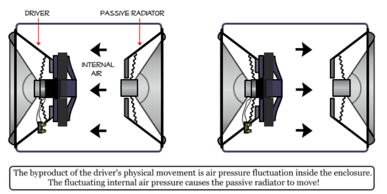 modest island
The cylinder is 'mostly' closed. Just some air gaps where buttons are placed at the top.
But I 'could' make it fully closed by adding a wall separator behind the speaker.
But I assume it will need 'some' air pocket behind it anyways?
glacial spruce
It doesn't have to be. Basically if it's closed (this is known as "acoustic suspension" in speaker builder jargon), the air behind the speaker acts as a spring, which makes it harder to move the speaker. This can be alleviated by putting some sound absorbing material behind it, or by having openings in the enclosure ("ports" in speaker builder parlance), resulting in what's known as a "bass reflex" design. Often the ports will have tubing associated with them to tune the moving air mass.
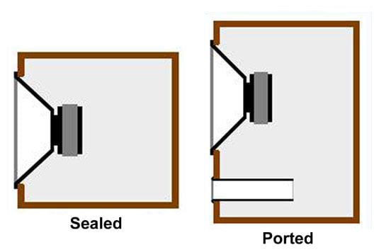
To get truly fancy, you can fold up a horn design and put it in your cylinder (3D printing is great for this sort of approach). https://i665.photobucket.com/albums/vv13/djryank94/untitled.jpg

This somewhat rambling video explains building a folded horn and including stiffening and damping such as plaster of paris. While it's probably massive overkill for your project, it does contain some interesting thinking. https://www.youtube.com/watch?v=XEspOD1NHr0

3D printed speakers can sound so good! Ad: Get an exclusive NordVPN deal here
https://nordvpn.com/diyperksvpn it’s risk-free with Nord’s 30-day money-back
guarantee!
Want to build these speakers for your own gaming or TV setup? The 3D printable files are available for $29.99 - https://payhip.com/b/dhJrS
Parts list:
Disclosure: These are affi...
rustic ibex
speaker enclosure building can get deep if you want. my impression as a spectator was that you start by deciding whether to make the enclosure sealed or ported and then calculate the interior volume based on your driver's specifications. I had the impression that interior volume was key. there are lots of enclosure calculators online.
dusty rivet
rustic ibex
speaker enclosure building can get deep if you want. my impression as a spectato...
Too bad this isn’t done for 90% of Bluetooth speakers sold these days lol
 limpid basin
Im making a lightsaber using all the same electronics from this tutorial :
https://learn.adafruit.com/lightsaber-featherwing/overview
except i decided to program it on my own in c++ using the arduino IDE.
got lights and such working, but cant seem to figure out how to do audio with it. is their a tutorial online someone could link me too? anything that talks about how to load wav files onto it/ play them would be great!

Adafruit Learning System
Use the force and Adafruit Feather to build a battle grade lightsaber!
glacial spruce
limpid basin
Im making a lightsaber using all the same electronics from this tutorial :
http...
As mentions on the PropMaker learn guide https://learn.adafruit.com/adafruit-prop-maker-featherwing/arduino-code "Arduino does not have great audio playback support". There are ways to do it with interrupts and buffering, but it's a little involved. Another approach would be to use a dedicated audio board that can handle playing files for you.
limpid basin
ok, ill look into that. thanks
coral silo
Here's the spirit Halloween Proton Pack speaker this thing is only 0.25w how powerful is the sound f don't want to blow this speaker up
 glacial spruce
coral silo
Here's the spirit Halloween Proton Pack speaker this thing is only 0.25w how pow...
glacial spruce
coral silo
Here's the spirit Halloween Proton Pack speaker this thing is only 0.25w how pow...
It's tough to actually burn out a speaker, but it'll start distorting the sound if overdriven. It's easy to swap in a better speaker. The Spirit pack is great for upgrading.
coral silo
glacial spruce
It's tough to actually burn out a speaker, but it'll start distorting the sound ...
I'm adding sounds to my neutrona wand much like the spengler wand has sounds
glacial spruce
Ah, excellent.
Note that (as in the other speaker discussion you can see if you scroll up some) a baffle or enclosure can greatly increase the efficiency of a speaker, especially a small one.
coral silo
glacial spruce
Note that (as in the other speaker discussion you can see if you scroll up some)...
the way the the spengler wand's speaker is at its in the heatsink and it resonates inside the body to make it appear louder - that's my plan hot glue it to my spirit neutrona wand's heatsink location and it will resonate in the body
what I did with some speakers off from amazon was face them to the plastic empty shell in my spirit proton pack and it made them feel louder in the areas I've picked
glacial spruce
Ah, that makes sense.
coral silo
coral silo
that's my plan to make it appear loud when it sounds inside the body of the neutrona wand
coral silo
same 0.25w speaker in the spengler wand not a 0.5...how this can appear louder in my neutrona wand' sbody?
glacial spruce
Different resonance? Different amplifier? Different sound samples?
coral silo
It this speaker can do this in the spengler wand then mine should have no issue of being loud
glacial spruce
Makes sense. If not, there are plenty of small inexpensive speakers capable of better performance.
glacial spruce
Relevant to two recent discussions: https://www.youtube.com/watch?v=Df2I4JIQzxs

Ellis, the MKBHD audio producer, found a speaker that just broke the laws of bass. Stay tuned until 2027 for the next Ellis presentation!
Watch Ellis’ last video - https://youtu.be/o-kJ4_CuWzA?si=V1k-bdIE7cxzPxz3
We Talk About These!
Brane X: https://geni.us/TrRz0c
Bang & Olufsen Beosound Explore: https://geni.us/rTiI9J
Yamaha HS5: https://gen...
 twin bloom
What does one use to get a numerical decibel value with a Raspberry Pi Pico (RP2040)? I am using the Pico specifically as it has an onboard power regulator to allow a 1.8v to 5v power input as I plan to use AA batteries with it.
desert fog
twin bloom
What does one use to get a numerical decibel value with a Raspberry Pi Pico (RP2...
Decibel value of what? The dB scale is just a logarithmic representation of a ratio.
twin bloom
desert fog
Decibel value of what? The dB scale is just a logarithmic representation of a ra...
SPL, background noise
desert fog
Ah, so for that you'll just need an appropriate microphone. The RP2040 should have more than enough processing power to calculate what you need from that. Calibration might be a pretty arduous task though.
twin bloom
I've seen a microphone with an LM386 amp to amplify the signal for an arduino ADC.
Calibration is my main concern with it
desert fog
For that, you will likely need some sort of reference source, and possibly an anechoic chamber.
 frank ivy
what about a pre-calibrated one? I2C https://pcbartists.com/product/i2c-decibel-sound-level-meter-module/ or analog: https://www.dfrobot.com/product-1663.html
desert fog
frank ivy
what about a pre-calibrated one? I2C https://pcbartists.com/product/i2c-decibel-...
That could work, although the 30Hz to 8kHz range may be problematic depending on your application.
 wheat jetty
Hey, is it possible to set the advertised service UUID on the Bluefruit UART Friend module?
My goal is to connect to it via my Arduino 101 board, which only has the capability to scan for specific UUIDs.
 fallow grove
Our cat chewed through my brother's headset wire and I'm wondering what the best way to splice it back together is. I'm a bit confused by these smaller wires around the central white one, they seem to be just colored copper strands twisted around eachother. Can I just solder them like normal or do I need to do something special? There was string in the wire aswell, I'm assuming to prevent those wires from touching.

It seems like it might be a coating or something, because my multimeter doesn't register a connection when I test two spots on the same wire
glacial spruce
That's known as "tinsel wire", and it's fairly annoying to work with, you have to remove the coating thermally or chemically without destroying the very thin copper conductors.
 opaque quartz
I spent the morning learning and enjoying this and thought I'd share here...
https://www.audiolabs-erlangen.de/resources/MIR/FMP/C0/C0.html
Fundamentals of Music Processing using Python Notebooks
 muted elk
hello, I need to add a headphone jack to a pi zero 2 w, whats the smallest way possible to do that? I am under large size constraints
glacial spruce
muted elk
hello, I need to add a headphone jack to a pi zero 2 w, whats the smallest way p...
Too bad this is discontinued https://www.adafruit.com/product/4037

Discontinued - you can grab this Adafruit I2S 3W Stereo Speaker Bonnet for Raspberry Pi - Mini Kit instead!Add some easy-listenin' tunes to your Raspberry Pi using this basic audio ...
weary gyro
muted elk
hello, I need to add a headphone jack to a pi zero 2 w, whats the smallest way p...
The generic term for what @glacial spruce referenced might be “Pi DAC Hat” or “Pi Audio Hat”. There are many different kinds. Here’s one: https://amzn.to/45bGarJ

Discover the Raspiaudio Audio+ V2, the ultimate stereo DAC for your Raspberry Pi projects. This module offers high-quality audio output with a maximum sampling rate of 384 KHz and a signal-to-noise ratio of 112 dB, ensuring clear and noise-free sound. Designed to be compatible with a wide range o...
muted elk
Thank you!
frank ivy
@muted elk This one is also pretty small and affordable: https://shop.pimoroni.com/products/audio-dac-shim-line-out?variant=32343184965715

A super-simple, slimline way to hook up a hi-fi amp or powered speakers to your Raspberry Pi! Output punchy digital I2S audio whilst leaving your GPIO pins conveniently accessible.
muted elk
frank ivy
<@1041485099662852188> This one is also pretty small and affordable: https://sho...
Thank you! I will buy that.
muted elk
frank ivy
<@1041485099662852188> This one is also pretty small and affordable: https://sho...
I actually have a question. Is there a version of this that has a headphone amp built in?
glacial spruce
muted elk
I actually have a question. Is there a version of this that has a headphone amp ...
Learn how to use Pirate Audio boards and install their software – Pimoroni Learning Portal
muted elk
glacial spruce
Looks like https://learn.pimoroni.com/article/getting-started-with-pirate-audio
I actually was looking into that. It looks cool and fits my needs. But will it work with debian bulseye on a raspberry pi zero 2 w? it says to use debian buster.
glacial spruce
I can't say, but probably? It's an I2S audio device, which should be fairly well supported in general.
muted elk
glacial spruce
I can't say, but probably? It's an I2S audio device, which should be fairly wel...
I mean they have not changed the gpio pin layout since the pi 2
glacial spruce
Since they're both Debian derivatives, they probably support the same drivers in general
muted elk
glacial spruce
Since they're both Debian derivatives, they probably support the same drivers in...
Ok, But is there a demo video of the pirate audio? I wanna see the UI and stuff like that.
glacial spruce
I don't know, maybe some looking around on the site, youtube, etc. would turn up something
muted elk
glacial spruce
I don't know, maybe some looking around on the site, youtube, etc. would turn up...
I actually found a video from sparkfun electronics.
frank ivy
Tell you what, let me see if I can find mine, and I'll check it out right now
and we're off to a bad start, I just bent GPIO pins on the pi zero
frank ivy
root@raspberrypi:~/pirate-audio/mopidy# ./install.sh
Updating apt and installing dependencies
Get:1 http://raspbian.raspberrypi.com/raspbian bookworm InRelease [15.0 kB]
Get:2 http://archive.raspberrypi.com/debian bookworm InRelease [23.6 kB]
Get:3 http://raspbian.raspberrypi.com/raspbian bookworm/main armhf Packages [14.5 MB]
Get:4 http://archive.raspberrypi.com/debian bookworm/main arm64 Packages [416 kB]
Get:5 http://archive.raspberrypi.com/debian bookworm/main armhf Packages [425 kB]
it's not immediately bombing out
it's convenient that I had a pile of audio components and two pi zeros next to me when you asked this
oh no:
Adding Mopidy apt source
Hit:1 http://archive.raspberrypi.com/debian bookworm InRelease
Hit:2 http://raspbian.raspberrypi.com/raspbian bookworm InRelease
Get:3 https://apt.mopidy.com bullseye InRelease [14.1 kB]
Get:4 https://apt.mopidy.com bullseye/main Sources [5,797 B]
Get:5 https://apt.mopidy.com bullseye/contrib Sources [1,190 B]
Get:6 https://apt.mopidy.com bullseye/main arm64 Packages [3,869 B]
Get:7 https://apt.mopidy.com bullseye/main armhf Packages [3,869 B]
Get:8 https://apt.mopidy.com bullseye/contrib armhf Packages [1,695 B]
Get:9 https://apt.mopidy.com bullseye/contrib arm64 Packages [627 B]
Get:10 https://apt.mopidy.com bullseye/non-free armhf Packages [719 B]
Fetched 31.8 kB in 6s (5,599 B/s)
Reading package lists... Done
Building dependency tree... Done
that "bullseye" doesn't fill me with optimism
but I guess we'll see, the docs from mopidy say "bullseye and newer" is supported.
frank ivy
I'm going to go with, "I can't recommend this" - it seems like there were changes to the OS that make it non-obvious
how to get audio playing on bookworm

Mopidy Discourse
Hi all I have installed the lasest version of Pi OS onto a Raspberry Pi 4. I wont Mopidy to output via the headphone jack. I have tried to folllow the instructions at: https://docs.mopidy.com/stable/installation/raspberrypi/ The test aplay /usr/share/sounds/alsa/Front_Center.wav is correctly playing sound out of the headphone jack into the...
next up: adafruit voice bonnet
that might have to wait until tomorrow, I think I want to start with a freshly imaged pi
frank ivy
oh hey! I got it with the DAC shim!
you can install using the mopidy script (or at least, I did), but then there is a very silly problem
the old /boot/config.txt file is now at /boot/firmware/config.txt
so you need to manually modify /boot/firmware/config.txt with the following:
comment out dtparam=audio=on
make sure SPI is enabled with dtparam=spi=on
and add the following to the end:
gpio=25=op,dh
dtoverlay=hifiberry-dac
reboot, and then it is working for me
looks like the bookworm change has been made for the adafruit voice bonnet: https://github.com/HinTak/seeed-voicecard/blob/v6.1/install.sh, but there are notes that it's broken for rpi5 hardware.
random bone
frank ivy
looks like the bookworm change has been made for the adafruit voice bonnet: http...
could you add a "Feedback" in that guide? See the link in the left sidebar. Thanks.
frank ivy
Once I've tested, sure!
muted elk
frank ivy
I'm going to go with, "I can't recommend this" - it seems like there were change...
I could run Debian bullseye.
muted elk
Screenshot (Jun 6, 2024 4:54:58 p.m.)
There's a french review talking about it working with the zero 2w.
Screenshot (Jun 6, 2024 4:56:07 p.m.)

Here's the translated review. It says it works. Also I don't remember where I found it on pimoroni's website but I found something saying about it being compatible with the pi 5. But now pi zero 2. Just says pi zero. I mean I think it would work.
frank ivy
I had the DAC Shim working with the pi zero 2w on bookworm (debian 12 based raspberry pi OS), but the install script provided only works for older versions. I put up a PR that should fix the issue I ran into, but the author thinks there are other issues that need to be addressed. I am going to be testing the pi zero 2w with bookworm with the adafruit voice bonnet as well (which is the thing I meant to work on, but got sidetracked by the DAC shim)
muted elk
frank ivy
I had the DAC Shim working with the pi zero 2w on bookworm (debian 12 based rasp...
Ok Thanks!
coral silo
which one is good for switches? I need those loop when flipped on
 frank ivy
random bone
could you add a "Feedback" in that guide? See the link in the left sidebar. Than...
frank ivy
random bone
could you add a "Feedback" in that guide? See the link in the left sidebar. Than...
I tested the guide with a zero 2W and bookworm, and it worked perfectly for me. I did not test with rpi5
coral silo
here's what sounds I want to code in uart mode

I have fixed the order of the holding loops ones
coral silo
Plus the board is useless!
glacial spruce
coral silo
which one is good for switches? I need those loop when flipped on
Depending on you mean by "when flipped on", you probably want 2.
frank ivy
oh man, T01.wav is my jam
muted elk
frank ivy
I had the DAC Shim working with the pi zero 2w on bookworm (debian 12 based rasp...
Hey there is actually a volumio plugin that makes it work with the pirate audio! volumio is natively supported on the rpi zero 2. https://github.com/Ax-LED/volumio-pirate-audio

GitHub
Python code (Plugin) to use pirate audio dac with volumio (including display and the 4 buttons) and a raspberry pi. - Ax-LED/volumio-pirate-audio
frank ivy
Neat, but I've already got volumio running on an rpi4 with a hifiberry hat/dac, been running it flawlessly for years
muted elk
frank ivy
Neat, but I've already got volumio running on an rpi4 with a hifiberry hat/dac, ...
Volumio seems pretty cool, Im gonna test it on my pi zero
coral silo
guess I'll need an "amp" for the mini soundfx...I only have a 0.25w speaker to use
coral silo
best amp for the soundFX mini....don't want to damage the 0.25w speaker
glacial spruce
Any small amp should do. You can add a small series resistor to limit the power.
modest island
I am currently using a motion sensor detect taps. On each tap it should play a random sound.
            mixer = audiomixer.Mixer(voice_count=voice_index,
                                     sample_rate=wave.sample_rate,
                                     channel_count=wave.channel_count,
                                     bits_per_sample=wave.bits_per_sample,
                                     samples_signed=True)
            mixer.voice[0].level = volume
            audio.play(mixer)
            mixer.voice[0].play(wave)
            time.sleep(0.1)```


This kind of works - but if I tap the motion sensor too quickly - it wil create a very loud noise sound and then stop altogether.

Is there a way to prevent this?Try calling mixer.stop_voice[[0].stop() to stop the current playing in case you get a tap when something is still playing
modest island
ah yeah that seems to help
One other question - sometimes I get this "crackling" sound for half a second. Is there a wa to prevent that?
random bone
modest island
One other question - sometimes I get this "crackling" sound for half a second. I...
which board is it? Are you doing anything else besides the tap detection (wifi, etc.)?
modest island
rp2040 propmaker - no wifi. Just sound, tapping
random bone
modest island
rp2040 propmaker - no wifi. Just sound, tapping
try setting the buffer_size in audioMixer.mixer larger, to 2048 or 4096. It's an optional argument: https://docs.circuitpython.org/en/latest/shared-bindings/audiomixer/index.html#module-audiomixer
modest island
Ok will try that - any negative sides if I put it to 4096 instead of 2048?
random bone
modest island
Ok will try that - any negative sides if I put it to 4096 instead of 2048?
probably not - the RP2040 has plenty of RAM. You could double it again or more if necessary
weary gyro
modest island
I am currently using a motion sensor detect taps. On each tap it should play a r...
Are you constructing the audiomixer.Mixer once at the top of your code, or each time you play a sound? It should be the former. There may be a click/pop when you first attach the mixer to the audio device, but every mixer.voice[0].play() will not have a click. If it does click, as Dan says, add buffer_size=2048 to the Mixer init
 feral siren
Came looking for similar advice on a project on I'm working on. Cheers!
modest island
Another question for the audio - does it make sense to turn off the "external power" when the speaker is not in use?
# external power
external_power = DigitalInOut(board.EXTERNAL_POWER)
external_power.direction = Direction.OUTPUT
external_power.value = True```
Basically setting this to false?And then I turn it on each time I want the sound to be played?
 sharp mirage
i'd like to record audio from the microphone on a pair of earbuds, the TRRS headphone jack kind, with a microcontroller (ESP32 in particular)
for the wiring/hardware part: i did a little research and it seems like i need to both feed the mic pin (ring closest to sleeve) some voltage ("DC bias") and then also amplify it with an amp designed for that type of microphone (electret?)
for the software part: according to this description i need to use some kind of FFT thing? https://www.adafruit.com/product/1063
glacial spruce
sharp mirage
i'd like to record audio from the microphone on a pair of earbuds, the TRRS head...
You don't need FFT to record audio, that's only useful if you want to analyze the audio.
modest island
Another question
mixer.voice[0].play(music)
Assuming I would have a voice_count of 100
to play multiple sounds at the same time
can the microcontroller even handle that?
Or is there an upper limit of let's say max. 3 at the same time
weary gyro
modest island
Assuming I would have a voice_count of 100
realistically, the max number of voices is around 10-20. What is it you're trying to accomplish?
sharp mirage
glacial spruce
You don't need FFT to record audio, that's only useful if you want to analyze th...
ah got it. i don't need to do analysis but i do need to turn it into pcm audio data to send over serial
sharp mirage
what's the equivalent of this example https://learn.adafruit.com/stemma-audio-amp/arduino for an ESP32 feather?
 glacial spruce
sharp mirage
what's the equivalent of this example https://learn.adafruit.com/stemma-audio-am...
glacial spruce
sharp mirage
what's the equivalent of this example https://learn.adafruit.com/stemma-audio-am...
The CircuitPython one seems like it would work out of the box. Not sure of the Arduino driver coverage.
sharp mirage
glacial spruce
The CircuitPython one seems like it would work out of the box. Not sure of the ...
i tried CircuitPython on my Feather ESP32 V2 and it flashed successfully but I couldn't figure out how to actually start a REPL. Mu didn't detect any devices attached, and if i tried to use the serial port directly it would send bytes that didn't look like text as if i wasnt meant to use it directly like that
glacial spruce
That does sound like an issue, but I don't know how to solve that one. Maybe ask in #help-with-circuitpython
sharp mirage
ill post it there thx!!
sharp mirage
glacial spruce
The CircuitPython one seems like it would work out of the box. Not sure of the ...
tried the circuitpython one but it says "no module named audiopwmio"
will also post that in the other channel actually
 mild sapphire
Re: the Adafruit Audio FX Sound Board. I’m trying to understand the difference between the boards when it comes to attaching a speaker (some boards have a built-in amplifier?)
I’m leaning toward board #2220 (16MB) but I’m open to others. I’m trying to place an order and want to make sure I’m purchasing all of the required components.
What kind of speaker do I need? Something soldered to the board like an Adafruit speaker #1313 (3-Inch Speaker 8 Ohm 1 Watt)? Or could I just plug any speaker into the headphone jack? Do I need to power the speaker itself?
Thanks in advance.
glacial spruce
mild sapphire
Re: the Adafruit Audio FX Sound Board. I’m trying to understand the difference ...
#2220 doesn't include a speaker amplifier, you might want to choose one that does (such as #2217) if you intend to hook it to a speaker. The ones with amplifiers come with terminals, so you don't have to solder the speaker directly to the board, you can solder the terminals in place then use the terminals to easily attach and remove speaker wires. You can use pretty much any 4 to 16 ohm speaker, including the one you referred to.
mild sapphire
glacial spruce
#2220 doesn't include a speaker amplifier, you might want to choose one that doe...
That sounds great! Thanks very much for your help!
coral silo
could I basically use any pin for uart mode for the sound FX? I might have to do this if I use 10 pins of the uno to power up a 10LED bargraph
glacial spruce
Some boards have one or more hardware UARTs, making the pins those are connected to logical choices. However, you can often use SoftSerial or similar to use any pin to send asynchronous serial data like that.
 rancid hollow
Are there any project tutorials for the Grand Central out there that go through the DAC and audio project capabilities/limitations of the board more in depth? Ideally looking for a project that's used relatively larger and louder speakers than the basic soundboard tutorial on the website.
weary gyro
rancid hollow
Are there any project tutorials for the Grand Central out there that go through ...
That soundboard example is taking the (approximately) line-level output from the SAMD51 DAC on the Grand Central and feeding it into powered speakers. The loudness of the speakers is driven by the speakers themselves, the Grand Central has not much to do with that. For better speakers than those listed, I'm a fan of decent bluetooth speakers with line in: they have great bass response and are battery powered
rancid hollow
Gotcha. That helps, I'll just look for off the shelf powered speakers that look more uhh, powerful than the desktop ones in the tutorial lol.
glacial spruce
That, or plain ordinary speakers plus an audio amplifier (such as https://www.adafruit.com/product/987).
rancid hollow
would that amplifier be suitable for an art installation that takes up an entire room? Seems like it's for more desktop style speakers. the 20W one looks nice: https://www.adafruit.com/product/1752 but only has a headphone jack input and I'm not sure how to splice into a cable like that for permanent install. Could I just remove the jack and solder wire directly from the Grand Central to the amplifier board?

Pump up the volume with this 20W stereo amplifier! This slim little board has a class D amplifier onboard that can drive 2 channels of 4-8 ohm impedance speakers at 20W each. Power it with ...
oh nvm I just saw the 20W one has stereo in terminal blocks too lol. Should work fine then theoretically
 whole arch
As this is help with audio, is it fair to ask questions on windows audio problems? I've got a dell tablet pc that's actin funny.
random bone
whole arch
As this is help with audio, is it fair to ask questions on windows audio problem...
you could, or maybe #general-tech , which has more eyes
whole arch
random bone
you could, or maybe <#327254708534116352> , which has more eyes
Thanks. I just posted in the General tech channel.
 placid copper
Hey Folks, is there any tutorial or something like that which I can learn more about connecting a mini speaker and microphone to adafruit gemma M0? Not sure if this is the right forum for this question if not please let me know where should I ask the question. Any help is appreciated.
glacial spruce
What are you trying to accomplish? You can hook a microphone to an analog pin, but you may need a pre-amplifier. You can hook a speaker to the analog output pin, but you'll probably need some sort of amplifier.
placid copper
I want to know what can be accomplish with this adafruit gemma m0. I wonder if I can use some of the capabilities to connect this microphone and communicate with adafruit gemma m0 and play some sound through a speaker 🔊.
glacial spruce
You can easily do beeps and boops, and since the M0 has an analogue output, you can play higher fidelity sounds. However you will need an amplifier to drive a speaker. I'm not sure what you have in mind by "communicating" via microphone.
placid copper
Thanks, I probably need more than simple beep sounds, I am thinking more in line of a youtube track or something similar.
Another question, is it possible to connect M0 to a phone using Bluetooth?
Is there a manual that I can look into the audio functionality of M0?
random bone
placid copper
Thanks, I probably need more than simple beep sounds, I am thinking more in line...
m0 itself has no BLE. Espressif or nRF would be the choice
placid copper
random bone
m0 itself has no BLE. Espressif or nRF would be the choice
Great to know. Let me check those as well.
random bone
placid copper
Great to know. Let me check those as well.
are you interestedin Arduino or CircuitPython?
placid copper
I didn't work with any of these two yet. But I do know how code in python so probably circuitpython will be my choice. A few days ago I purchased 2 adafruit gemma m0 which I think it supports circuitpython
random bone
placid copper
I didn't work with any of these two yet. But I do know how code in python so pro...
It does. Have you looked at our extensive Learn Guides? https://learn.adafruit.com/
placid copper
random bone
It does. Have you looked at our extensive Learn Guides? <https://learn.adafruit....
Thanks for sharing. Looking into it...
 sand cove
For some reason this MAX9744 isn't working, on my bench power it only draws 4 volts, so something must be wired wrong right?
 glacial spruce
Devices do not draw voltage, they draw current
dusty rivet
glacial spruce
Devices do not draw voltage, they draw current
It’s always an interesting to think about. Devices draw current, but certain semiconductors operation is dominated by the voltages applied rather than the current itself. But everything comes down to current regardless as you mentioned.
And thanks to Ohms law, we know it all works together in the circle of circuit life
frank ivy


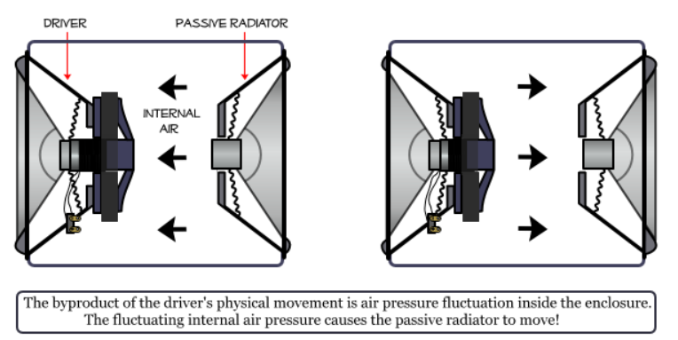
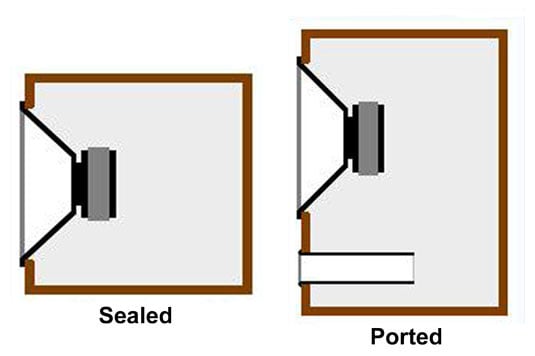


 hoary shard
whoooosssshhhh !
rustic ibex
life in the Serengyeeti
 frigid galleon
``void setup() {
Wire.begin(); // I2C //
// Start the serial interface
Serial.begin(57600); // Initialize serial communication with a baud rate of 57600
///////////////// needs fixing ///////////////////
if (timeStatus() != timeSet)
Serial.println("Unable to sync with the RTC"); // Print error message if unable to sync with RTC
else
Serial.println("RTC has set the system time");  // Print success message if RTC has set the system time
while (!Serial)
;
{
;
} ``
I am having a problem with the above code, I know the RTC is keeping time and I know the Arduino is getting the time from the RTC. When I power cycle the Arduino the time is still there and correct I am using the DS3231.h file and the RTC 3231. I get the message "Unable to sync with the RTC" so it has to be a code issue in this section as tis is where the test is run. Help would be greatly appreciated as I do buy Adafruit products all the time one of the purchases was recently the 1947 TFT display. So in short all I want to know is if the Arduino got the time from the RTC with a simple test, I thought it was coded correctly obviously it is not
Thank you in advance
glacial spruce
I'm unsure why it isn't, but what I'd try is waiting a bit before checking (maybe move that block after the wait for serial to be ready one), insert a small time delay, or maybe try twice before giving up. Sometimes the bus wires are jangled during a reset and the devices are confused and think they're in the middle of a command so don't respond correctly.
modest island
Posting also here just in case:
On my code (circuitpython on RP2040 propmaker) I often play sound files. Sometimes it does other things and then I get this weird crunching or pop sound on the speaker for a short time.
How can I avoid that?
Do I need to cut off the power supply to it?
For example I read a CSV file with 60+ rows. It would pop like 3-4 times during those 2-3 seconds or so where it reads the file.
I am already using the mixer
It's not playing any sound files while reading the csv file in case that matters
glacial spruce
I wonder if something like a chip select isn't being disabled, so the sound chip is reacting to bus traffic when it should be idle.
 cursive rune
does anyone have a favorite I2S DAC breakout that can drive a line-level signal?
seems like everyone is using the MAX98357 which is a cool chip but I'm trying to make an electronic instrument and need to be able to run the signal into an audio input or external amp
it looks like clones of the adafruit UDA1334A breakout are available
are there any mono equivalents?
weary gyro
cursive rune
does anyone have a favorite I2S DAC breakout that can drive a line-level signal?
I am a big fan of the cheapie PCM5102 modules: https://todbot.com/blog/2023/05/16/cheap-stereo-line-out-i2s-dac-for-circuitpython-arduino-synths/
cursive rune
weary gyro
I am a big fan of the cheapie PCM5102 modules: https://todbot.com/blog/2023/05/1...
are there any references you can point me at to read up on the differences between the various common chips/breakouts? or are they all similar enough
I forget if I've discussed the actual project here in the past, but it's been on the back burner for quite a while
trying to make a synthio-based electronic accordion
weary gyro
cursive rune
are there any references you can point me at to read up on the differences betwe...
I'm not aware of such a document, but that's a great idea. You could try searching for "i2s" on learn.adafruit.com and learn.sparkfun.com to get a sense of what I2S parts have been stocked by two companies who are very good at finding good parts. In my experience, there's roughly three different categories of I2S devices: I2S DACs that output line-level (e.g. PCM5102, UDA1334A), I2S DACs that directly drive speakers (MAX98357), and then the "codecs" that have I2S DACs and ADCs and mixers and can drive both line-level and speakers and must be configured via I2C before using them with I2S (WM8960, TLV320)
cursive rune
theoretically the electronics are "functional" but the audio is bad at the moment because it's pico-based and there's too many voices
aside from crunchy audio, the main thing I still want to fix is to have the audio output branch through a 1/4" switched stereo jack to either internal speakers or a line-out
weary gyro
cursive rune
aside from crunchy audio, the main thing I still want to fix is to have the audi...
I've been wondering about doing something similar and why I've been investigating those codecs that have both line-level driver and a speaker amp. But it also just seems really simple to drive a PCM5100 and a MAX98357 from the same I2S pins 🙂
cursive rune
certainly simple to do that, but IMO less "elegant" than piping analog audio through the jack & amp
in the sense that it's kinda neat to plug in and have the speakers switch off automatically
 opaque viper
Wrong place - I have a radio issue - ignore
tranquil isle
Hoi, what's the smallest, yet capable amplifier that can amp up this iphone 13 speaker? As this is max volume in windows, even with the "great 600ohm capable amp" my mobo has lol. but as this is for a project i have for my phone, i need a tiny, or as tiny amp i can get that can operate from a small rechargeable battery, or just hook up with cable to my phone over usb C.
glacial spruce
Your problem is probably supply voltage: 600Ω: 5V can push less than 8mA through that much impedance. Even a little TL072 op-amp running on 12V may be able to do better.
Then again, I wouldn't expect an iPhone speaker to be 600Ω
Are you sure that's the speaker and not (say) a haptic transducer?
 analog swallow
anyone know how many watts the pyportal titano can support in speaker?
random bone
analog swallow
anyone know how many watts the pyportal titano can support in speaker?
The audio amp is a PAM8301, which is a 1.5W amp. See the third schematic on this page: https://learn.adafruit.com/adafruit-pyportal-titano/downloads
glacial spruce
analog swallow
anyone know how many watts the pyportal titano can support in speaker?
The wattage doesn't limit the speaker, you can hook a 100W speaker to a 1W amp and it will work just fine (in fact, larger speakers are often more efficient than small ones)
analog swallow
Yeah I kinda wanted to thread the needle due to limited space
desert fog
glacial spruce
The wattage doesn't limit the speaker, you can hook a 100W speaker to a 1W amp a...
Well... the 1W amp may not be able to energize the coil sufficiently.
 cold nimbus
This is from the datasheet of a microphone. How am I supposed to interpret it? If it were just one line, I'd understand it (a 10k signal would be +6dB than "normal"), but what's the second line?


The fact that they appear to cross is also throwing me off
random bone
cold nimbus
This is from [the datasheet of a microphone](https://wiki.analog.com/_media/univ...
I agree, that is ... strange, especially since the two curves are unlabeled. If you look at the previous page on the datasheet it looks like they tested 10 items from a batch. I wonder if those are the two extreme frequency responses in the batch. But I am just guessing, and in that case, why not plot all ten?
Note that mic frequency responses are often normalized to 0dB at 1 kHZ. That explains why they cross there.
cold nimbus
that was my thought as well
on the first page is says the sensitivity is -45 dB ± 3 dB. There's ±3 dB between the lines for most frequencies, only really deviating at the extremes on either end of the frequency range. I feel this may be saying that the mics'll (most likely) be between the wo lines?
random bone
maybe it just says that in the batch they tested, that's what they got. It's kind of a small batch. Another thing is this:

not sure if that represents a test condition or not (2v vs 1.5V) , but if so, still don't know which graph line is which
I looked at some other datasheets for electret mics and I don't see this
for example https://www.cuidevices.com/product/resource/cma-4544pf-w.pdf for https://www.adafruit.com/product/1064

This electret capsule microphone is the same one we use in our great microphone amplifier board. It contains a small vibrating element that will output a few millivolts peak-to-peak. You ...
cold nimbus
random bone
not sure if that represents a test condition or not (2v vs 1.5V) , but if so, st...
it was tested at 2V. They're saying that if you go down to 1.5V supply you can expect the sensitivity to drop by 3 dB.
well, it's in the max column
so if you go down 0.5V the sensitivty will drop at most 3dB
Still, it's a weird thing to not label the graph and just expect people to figure it out lol.
random bone
i think you should just contact them if you need to know. But I can't find good contact info for them either
cold nimbus
👍
glacial spruce
cold nimbus
This is from [the datasheet of a microphone](https://wiki.analog.com/_media/univ...
Might be on-axis and off-axis
cursive rune
working with synthio and a MAX98357 and finding that at louder volumes stuff gets kinda
crunchy
what can I do to figure out why this is happening?
 odd oasis
If you have access to a nice oscilloscope, my first instinct would be to probe the amp output.
cursive rune
I'm pretty sure it's earlier in the chain
probably within circuitpython
my guess is clipping
weary gyro
cursive rune
working with synthio and a MAX98357 and finding that at louder volumes stuff get...
Are you doing multiple voices in synthio? Or filter with high resonance? If so, those can easily cause clipping. Synthio tries to do auto-gain but it’s actually a hard problem. E.g. add two full-scale 16-bit signals and you get a 17-bit signal, so what do you do? So divide all input signals by two is fastest, now everything is too quiet. Or when a filter has high Q, it resonants, effectively adding to the signal. So now you’re back to the signal being bigger than you can store.
What I’ve been lately is trying to make waveforms that aren’t full scale
cursive rune
weary gyro
Are you doing multiple voices in synthio? Or filter with high resonance? If so, ...
I'm running two channels (hard pan L/R) and noticing that when the crunch shows up on one channel, it sometimes pollutes the other channel also (even if there's theoretically no audio on the other channel)
weary gyro
cursive rune
I'm running two channels (hard pan L/R) and noticing that when the crunch shows ...
Hmmm, that sounds like something in the amp you're using. If you had a line-out I2S amp and an oscilloscope you could check that
cursive rune
gonna get one of those boards you recommended and see if it helps
 oak bobcat
Ok so I have the adafruit audio FX soundboard and I want these 5 arcade keys to activate 1 of 5 sfx. Now there is a caveat that it has to play the whole sound before you can play the next one. I read there is a way via UART mode to get rid of the delay and have it so that when you press a button and a sound plays then press another button it immediately stops the current sound and plays the next one


I already have 1 soundboard in the wooden case that activates the gold buttons on the front. The white piano part will basically function as a SFX piano
odd oasis
oak bobcat
Ok so I have the adafruit audio FX soundboard and I want these 5 arcade keys to ...
Using UART mode, you can command the soundboard to stop the current file and start a different one. However, to do so, you need to rewire your buttons to a microcontroller and program the microcontroller to send the commands over UART. The board can only be button-triggered or UART controlled, not both at the same time.
oak bobcat
odd oasis
Using UART mode, you can command the soundboard to stop the current file and sta...
I do know I need another board. I have an arduino uno that I plan to use. My question is I don’t know how to get it to work with the individual buttons
I’m not savvy with arduino code
odd oasis
When the Arduino detects a button press, the Arduino should be programmed to send the stop command and the play command. Follow the guide page linked above to install the library and load the demo to play with the commands over serial, then add code for buttons when you're ready.
odd oasis
oak bobcat
I’m not savvy with arduino code
Everyone starts somewhere. Start by learning to read button presses, then learn how to send serial commands. Once you can do those two things, putting it together should only be a matter of adding those two things to the demo.
oak bobcat
I'm trying but I undertstand nothing
I have the arduino hooked up correctly
to the soundboard
it IS in uart mode
I found a simple button code that I used to test if its seeing if the button is pressed
and it is
but other than that I'm completley suck
thats essentially what I'm trying to do
Code: Select all

  sfx.playTrack("T00     WAV");
  delay(200);
  sfx.playTrack("T01     WAV");

and have the T01.wav play 0.2 seconds after T00.wav. If you increase the delay so that it's longer than T00.wav, then T01.wav plays as expected.

But what you can do is stop playback. For example, this:

Code: Select all

  sfx.playTrack("T00     WAV");
  delay(200);
  sfx.stop();
  sfx.playTrack("T01     WAV");

plays T00.wav for 0.2 seconds, then abruptly stops, and then starts playing T01.wav.

That's the main advantage here. With the simple non-serial button read approach, it only reads the buttons after a track is done playing. But with serial control you can stop whenever. So the idea is to replace the delay() above with code that is reading your button(s). That way when you press a button it would stop any current playback and start whatever one you want next. Or if you don't press the button(s), the sound plays all the way through.```What I'm stuck on is like in this post, replacing the delay with a button press
So I shouldn't say I understand NOTHING I just don't understand the specific thing I want to do
tepid grove
oak bobcat
So I shouldn't say I understand NOTHING I just don't understand the specific thi...
Have a look at how the menu example works (File->Examples->Adafruit_Soundboard->menu) as mentioned in the linked guide page for Serial audio control.
Instead of checking which character was sent, you could check each if button is pressed. See here for the pause/unpause/stop: https://github.com/adafruit/Adafruit_Soundboard_library/blob/master/examples/menucommands/menucommands.ino#L142-L158
So whenever a new key was pressed (assuming it wasn't already pressed), then stop the sfx board and play the new sound effect
oak bobcat
tepid grove
Have a look at how the menu example works (**File->Examples->Adafruit_Soundboard...
I'm still having difficulty with the button press code
How do I check for a button press, how do I code that?
Here's another thought
Is there any OTHER adafruit board that can allow me to play the buttons like a piano keyboard but with SFX?
The soundboard works but the fact that I need a seperate board and code to get the effect I want is cumbersome
Plus ideally I'd want to use a single board
There's a few boards I was looking at but they all require midi
I'm not looking to create a midi controller
I'm looking to create a self contained instrument
odd oasis
oak bobcat
How do I check for a button press, how do I code that?
https://docs.arduino.cc/built-in-examples/digital/Button explains the basics pretty well.
For your case, though, https://docs.arduino.cc/built-in-examples/digital/StateChangeDetection/ is probably better, as this allows you to send a sequence of commands once per press.
glacial spruce
Sounds like a job for a Makey Makey board
oak bobcat
glacial spruce
Sounds like a job for a Makey Makey board
Currently looking into it…it looks like an NES controller
I assume I could hook the alligator clips to the ends of the buttons I have then have each one play a WAV sound?
Wait can I load the WAV sounds directly on the board itself or do I need another controller attached to the board that is running software to play the sfx?
I need something small and self contained
If I have to plug it into a laptop every time I want to use it then load up software that completely defeats the purpose of what I am trying to do
 uneven harness
I'm planning to swap out my grey eurorack ribbon power cables for black ones, but I'm having a hard time sourcing them. Adafruit sell the one I like but it's 12" and I don't trust my crimping skills enough to mod it. Anyone know a place that sells qualified cables such as these? For the curious... Adafruit Product ID: 4170
glacial spruce
uneven harness
I'm planning to swap out my grey eurorack ribbon power cables for black ones, bu...
Various companies can make them up for you (I suspect DigiKey can, they do stock the cable and connectors). Not a lot of skill is required for IDC connectors like these, however, just feed the wire through and compress it (custom tools exist, but a small bench vise does a dandy job)
 winter hare
I moved into a place with built in wall speakers but i have no idea how to connect to it any help


 echo hedge
winter hare
I moved into a place with built in wall speakers but i have no idea how to conne...
echo hedge
winter hare
I moved into a place with built in wall speakers but i have no idea how to conne...
You'll need a receiver to drive them
glacial spruce
Looks labeled, but you can just check the jacks with a multimeter to see which have continuity. You should see a low resistance (4-40Ω) for each speaker. Hooking an amplifier to that set of jacks should send sound out of the speaker connected to them. Then just hook each one how you want.
frank ivy
and those jacks look like they could probably accept bare wire or banana plugs
glacial spruce
Yeah, they look like "5 way" binding posts that can accept a variety of terminations
 sweet bay
I'm looking to see if the MAX98357 I2S can do eurorack line level audio (10v p2p) if it's set to 15db of gain.
weary gyro
sweet bay
I'm looking to see if the MAX98357 I2S can do eurorack line level audio (10v p2p...
No in two ways: first, the MAX98537’s max input voltage is 5.5v. Second, that chip is designed to directly drive low-impedance speakers, its output pins are not referenced to ground
 naive bay
Hello all! I have an audio hurdle I’m reaaaally hoping someone can help with. I have a prototype music device running ESP32 and PCM5100. We have it powering, receiving code, but no audio. Not sure if it’s hardware or code? Does this look correct? Much appreciated

 weary gyro
naive bay
Hello all! I have an audio hurdle I’m reaaaally hoping someone can help with. I ...
weary gyro
naive bay
Hello all! I have an audio hurdle I’m reaaaally hoping someone can help with. I ...
I would always do as much as you can in a breadboard first to test out software. E.g. try wiring up an ESP32-Wrover dev board and a PCM5100 module and see if your code works on that. Then you could eliminate the code as a problem.
But from your schematic I see two issues:
- the name is the nets don’t match: on the ESP32 part a net is called “To_Codec_DIN” but in the PCM5100 part it’s called “Codec_DIN”
- ESP32s have a few very important “strapping pins” that must be treated specially and cannot be used generally. In your case IO0 and IO5. I think you’re okay in this case, but trying it all out on a breadboard would answer that
naive bay
Thank you Todbot! I’ll pass this onto my friend who now has the prototype. I notice the nets named ‘To_”. Could be this simple! Will see. I think we were cautious about the strapping pins, but hey, I’ll check again too.
coral silo
decided not to make it - how to know the mic pick up and be loud on speaker? is it -XXXdba higher or lower to be loud?
glacial spruce
positive dB (of whatever flavor) are louder, negative are softer
coral silo
https://mou.sr/47dUXTL this one is a -32dba with 2kohms to get it working
glacial spruce
That... is a microphone.
Specifically, it's an electret condenser microphone with a built-in FET amplifier
So you'll need to supply a bias voltage to power the amplifier and AC couple the audio output
coral silo
That's what I need to replace in the walkie talkies with them reusing the ones from the paw patrol ones the factory have them under some melted plastic to keep them in
glacial spruce
You may need a little circuitry
 misty schooner
I'm using the pygamer to try and play audio samples. everything works when calling arcada.enableSpeaker(true); to enable the speaker amp. When looking at the code (https://github.com/adafruit/Adafruit_Arcada/blob/4ddc5ef2405fa28442042df2dccd950707c26dd8/Adafruit_Arcada.cpp#L245)arcada.enableSpeaker(true); is really just setting pin 51 to high, but when just doing this with the standard digitalWrite(51, HIGH); it doesn't work and no sound gets played

GitHub
Arduino library for gaming. Contribute to adafruit/Adafruit_Arcada development by creating an account on GitHub.
glacial spruce
Are you configuring the pin as an output?
misty schooner
yes
misty schooner
glacial spruce
Are you configuring the pin as an output?
using arcada also causes the arduino sd library to not work
so I want to avoid it
glacial spruce
What GPIO are you setting high?
misty schooner
glacial spruce
What GPIO are you setting high?
pin 51
from the pygamer config file https://github.com/adafruit/Adafruit_Arcada/blob/4ddc5ef2405fa28442042df2dccd950707c26dd8/Boards/Adafruit_Arcada_PyGamer.h
GitHub
Arduino library for gaming. Contribute to adafruit/Adafruit_Arcada development by creating an account on GitHub.
glacial spruce
Is pin 51 the same as GPIO 51?
misty schooner
I don't know but in the arcada library they set pin 51 to high using just the standard arduino functions so I think It's the same
glacial spruce
That should work. How are you generating audio?
misty schooner
by setting the A0 pin using analogwrite
my code works fine when using the arcada lib to turn on the speaker amp
it's just that I can't turn on the speaker amp without arcada
misty schooner
misty schooner
I don't know but in the arcada library they set pin 51 to high using just the st...
this is the line where they do that
GitHub
Arduino library for gaming. Contribute to adafruit/Adafruit_Arcada development by creating an account on GitHub.
glacial spruce
I agree, it ought to work, and the circuitry isn't that complicated. Therefore I suspect something else is wrong.
 gleaming linden
Is it possible to use two audio FX boards with one stereo amp? The amp I have has a 3.5mm stereo aux jack that I'm guessing I would use a left/right splitter. Then on the output, it has left/right channels so must I use two speakers or can I use one mono speaker thus getting the sounds from both boards on one speaker.
 glacial spruce
Some amplifiers won't let you combine the speaker outputs, but if you want a single speaker anyway, you could build a simple mixer or combiner to combine the outputs of a couple of Audio FX boards, then use the combined signal with a mono amplifier.
gleaming linden
glacial spruce
Some amplifiers won't let you combine the speaker outputs, but if you want a sin...
Ah, since the boards are stereo, a splitter (not separating the channels) in reverse would get the signal from both boards to the amp. Would there be a issue for the signal from one board going back up the the output of the other board?
glacial spruce
Ah, didn't realize they were stereo. You'd want something in-between to avoid having the boards' outputs fight, something like series resistors would do (that's basically what a "passive mixer" is)
 grim robin
@weary gyro couldn't find a way to contact you. I made a board inspired by your touch and synth designs (except that it uses c++ as circuitpython was too slow for my use). I can mail you one if you are interested.

I am organizing a workshop next week where I'm going to show people how they can design their own, how midi works and just jam with them
(rp pico clone, i2s module pcm5102, i2c display, 8 pots with analog mux, 12 touchpads)
the objective was to make a sub $20 module that can do midi controller and synth. Ended up at $25/each for 20 units so not too far. I kept one for you and one for the person that designed the creative commons licensed synth I use in it (which is pretty impressive)
weary gyro
grim robin
<@352910176736772096> couldn't find a way to contact you. I made a board inspire...
Very cool! Looks highly useful. Love using analog mux to give more inputs, feels almost like cheating 🙂
grim robin
It is all OSHW too. But the repo is still a mess https://github.com/bjonnh/2024_emmg_workshop_midi/tree/main

GitHub
Contribute to bjonnh/2024_emmg_workshop_midi development by creating an account on GitHub.
grim robin
weary gyro
Very cool! Looks highly useful. Love using analog mux to give more inputs, feels...
i was also out of pins. but next design will have a touchpad controller as well. it take way too much cpu cycles just for that.
(and with 12 touchoads the PIOs are not enough)
weary gyro
grim robin
I am organizing a workshop next week where I'm going to show people how they can...
Good luck on the workshop! Getting everything ready is a big task but looks like you got things under control
weary gyro
grim robin
i was also out of pins. but next design will have a touchpad controller as well....
yup know that feeling 🙂
grim robin
did you finally get working touchpads on the rp2350?
(one more reason to move to an external chip)
weary gyro
grim robin
did you finally get working touchpads on the rp2350?
no, it's not possible with current silicon rev of the RP2350. So yeah, use one of the many I2C captouch chips.
grim robin
@weary gyro let me know if you want to receive one (free of charge obviously)
weary gyro
grim robin
<@352910176736772096> let me know if you want to receive one (free of charge obv...
oh sure! if you got a spare and you're sure you won't come up short for your workshop
grim robin
@weary gyro nah I planned one for you and one for the developer of https://github.com/risgk/digital-synth-pra32-u which I use for the synth part.

GitHub
4 Voice Polyphonic/Paraphonic Synthesizer for Raspberry Pi Pico/RP2040 - risgk/digital-synth-pra32-u
weary gyro
grim robin
<@352910176736772096> nah I planned one for you and one for the developer of ht...
cool! that pra32-u synth sounds awesome
grim robin
it sounds great, I still have to do some demo recordings of it, the ones on my website are from the older circuitpython synth that was not great
 dull basalt
How do we get 8 bit or 16 bit depth sounds to play using https://github.com/adafruit/Adafruit_ZeroI2S ? Looks like I2S->DATA[n].reg are 32 bit. I found I can get 16 bit depth i2s data to play by writing the 16 bit values left shifted 16 bits. This does not work for 8 bit data left shifted 24 bits however. The issue affects the use of DMA too. I'm trying to send 8 bit slot size 1 channel frames? to a max98357. My ultimate goal here is to DMA transfer the 8 bit samples right into the I2S peripheral from ram after reading chunks of it from SPI NOR flash.
GitHub
I2S audio playback library for the Arduino Zero / Adafruit Feather M0 (SAMD21 processor). - adafruit/Adafruit_ZeroI2S
i2s.begin(I2S_16_BIT, SAMPLE_RATE) where anything other than I2S_32_BIT results in no audio at all.
dull basalt
Turns out MAX98357A only accepts a stereo i2s bitstream at a minimum of 16 bit resolution. Using the stock arduino I2S library, 16 bit "stereo" (duplicate the other channel) can play at any valid sample rate.
glacial spruce
Hardware limitations, grump
 hollow zealot
I am just familiarizing myself with the Adafruit soundboard with amplifier. I hooked it up and I am powering it with four AA batteries. It's working but the volume is very low. I have triggered the volume pin but it doesn't seem to raise it much. I'm going to need this thing to be a ton louder. Any ideas?
I am using Adafruit Audio FX Sound Board - WAV/OGG Trigger with 16MB Flash

I am using these speakers
https://www.amazon.com/gp/product/B01CHYIU26/ref=ppx_yo_dt_b_search_asin_title?ie=UTF8&psc=1

2pcs 2" 4Ohm 3W Full Range Audio Speaker Stereo Woofer Loudspeaker for Arduino
glacial spruce
hollow zealot
I am just familiarizing myself with the Adafruit soundboard with amplifier. I ho...
The volume pins are a "tap up" and "tap down" sort, so you need several presses to raise the volume more than a little bit. Those speakers are not very efficient, too.
Note that your audio files also affect the volume, you'll want them to use the full range available or they'll be quieter than they can be.
hollow zealot
Thank you. Can you recommend more effieient speakers? They need to be powered by battery
Amplifying the wave form made it louder but it is not more distorted. Perhaps better speakers?
glacial spruce
Often "bookshelf" speakers are in a good spot in the efficient/small/affordable axes
glacial spruce
Since you have the amplifier already, passive (non powered) speakers make sense.
 bronze locust
I've got some excess speaker wire in my bookshelf speaker setup. Is self-EMI enough of a concern that I should cut it shorter rather than let it sit there?
 random bone
bronze locust
I've got some excess speaker wire in my bookshelf speaker setup. Is self-EMI en...
random bone
bronze locust
I've got some excess speaker wire in my bookshelf speaker setup. Is self-EMI en...
don't worry about it at all
bronze locust
Thx. Wrong order of magnitude i take it, lol
terse maple
if you are in a high-RFI environment and your amp lacks adequate RF snubbers on the output, it could cause oscillation, but that’s not very likely
bronze locust
There is a Wi-Fi 6 router about 3ft away from the amp (built into the other speaker) on the other side of the room, I'm guessing that's not big enough to matter?
This is the Edifier R1280DB, a pretty popular bookshelf speaker set
glacial spruce
It's a low impedance signal, and differential, so most things it absorbs will be cancelled out anyway. If you want to get (electrically) fancy, you could twist the cable, but that's a lot of bother, it will no longer want to lie there neatly, and the difference is going to be unmeasurably tiny anyway. Danh is right, don't worry about it.
terse maple
there are stories about interference entering amps via the speaker wires, but they often involve things like nearby broadcast band AM transmitters
 pliant widget
how hard is it to hook an esp32 up to a bluetooth speaker? I just need it to play a 20 second file on loop
weary gyro
pliant widget
how hard is it to hook an esp32 up to a bluetooth speaker? I just need it to pl...
If you're hooking the up with a 1/8" audio cable, it's really easy. Use an I2C DAC like the PCM5102 module. If you mean have the ESP32 act like a BLE Central and not a Peripheral and send audio over Bluetooth, I'm not sure I've ever seen that.
pliant widget
I just realized my bluetooth speaker has an audio in, so I think Im going to go that route, thanks
last prawn
Looks like it might be possible with https://github.com/pschatzmann/ESP32-A2DP
GitHub
A Simple ESP32 Bluetooth A2DP Library (to implement a Music Receiver or Sender) that supports Arduino, PlatformIO and Espressif IDF - pschatzmann/ESP32-A2DP
weary gyro
last prawn
Looks like it might be possible with https://github.com/pschatzmann/ESP32-A2DP
ooo neat
 real ether
I did some searches but couldn't find the answer. I'm trying to use a microphone with the qt py esp32-s3 from circuitpython
right now i'm trying with the mems mic breakout
https://learn.adafruit.com/adafruit-i2s-mems-microphone-breakout/pinouts
when i tried audiobusio.PDMIn I got NotImplementedError: PDMIn and reading through the docs it looks like at least in 2022 that wasn't implemented.
what's the best way to record audio from the esp32-s3? the docs say i should be able to use any pins as I2S pins

Digital MEMS Mic Madness!
echo hedge
real ether
I did some searches but couldn't find the answer. I'm trying to use a microphone...
CircuitPython doesn't support I2S input yet. PDMIn is slightly different
real ether
ah, dang. so i could either use arduino or find a different mic?
echo hedge
I don't know if arduino has support. I don't know what a good mic option for the s3 with circuitpython is
weary gyro
real ether
ah, dang. so i could either use arduino or find a different mic?
Yes, arduino-esp32 supports I2S In and I2S Out (and simultaneous in + out). The I2S API is described here: https://docs.espressif.com/projects/arduino-esp32/en/latest/api/i2s.html
Here's an example of doing I2S input https://github.com/espressif/arduino-esp32/blob/master/libraries/ESP_I2S/examples/Record_to_WAV/Record_to_WAV.ino
real ether
weary gyro
Yes, arduino-esp32 supports I2S In and I2S Out (and simultaneous in + out). The...
Thanks, taking a look at the code example, trying to figure out where these pin numbers are coming from. i can't find a pinout of the esp32-s2-EYE, which is what it shows in the comment at the top. trying to adapt it to my wiring on the qtpy esp32-s3
const uint8_t I2S_WS = 42;
const uint8_t I2S_DIN = 2;

const uint8_t SD_CMD = 38;
const uint8_t SD_CLK = 39;
const uint8_t SD_DATA0 = 40;```here's how i have mine wired

 eager tangle
quick one, does anyone know if it is possible to get mp3 files to play on the matrixportal m4 using a Adafruit STEMMA Speaker - Plug and Play Audio Amplifier. (it's connect to the i2c port on the matrix)
eager tangle
eager tangle
quick one, does anyone know if it is possible to get mp3 files to play on the ma...
Also to add i would use# wav file but they are way to big for the board
weary gyro
eager tangle
quick one, does anyone know if it is possible to get mp3 files to play on the ma...
The DAC on SAMD51 / M4 is on pins A0 (and A1, for stereo) https://learn.adafruit.com/adafruit-matrixportal-m4/pinouts#analog-connector-slash-pins-3072800
You should not be able to plug in the Stemma speaker speaker to the StemmaQT I2C port: they are different-sized connectors

CircuitPython Powered Internet RGB Matrix Display
eager tangle
sorry was talking about the wrong port, i mean the 4-pin Stemma QT connector
i have found want i need, i think.
signal aspen
Hi all quick question to see if something exists, I need to take an I2S source and convert it into a I2S sink, basically I have access to the I2S source but the pico AD2P implementation seems to only be able to read the data from a sink, does something like this exist? Hoping for some sort of IC. Alternatively I could use a ADC but I would rather maintain the digital signal.
glacial spruce
signal aspen
Hi all quick question to see if something exists, I need to take an I2S source a...
I think that's not the library you want: it's not an I2S library, it's an AD2P converter. However, there is an I2S library that will allow you to use PIO to recieve I2S data: https://arduino-pico.readthedocs.io/en/latest/i2s.html
signal aspen
glacial spruce
I think that's not the library you want: it's not an I2S library, it's an AD2P ...
Thats the thing the MCLK is output only. I'd need it to be input for my use which doesn't seem possible so I basically need to flip my signal
glacial spruce
I was hoping the library would do that. I2S isn't that complicated really, but it may be that you'd need some PIO programming to use MCLK as an input
signal aspen
I did a bit of reading last night and the author said that the pico cant do it for whatever reason but maybe
glacial spruce
That's irksome. I'm not clear on the details of what PIO can and can't do.
signal aspen
totally, I figured an external buffer role reversal kinda deal might be the best route 🤷♂️
something like this but digital to digital https://digilent.com/reference/pmod/pmodi2s2/reference-manual
 earnest dune
glacial spruce
That's irksome. I'm not clear on the details of what PIO can and can't do.
earnest dune
glacial spruce
That's irksome. I'm not clear on the details of what PIO can and can't do.
basically, its a small cpu, with ~128 opcodes of code memory
on a single clock, it can do an action like taking 1 bit from the FIFO, and presenting it on 1 pin, while also putting a static value onto another pin
and on a second clock, sample one pin, and push it onto a second FIFO
so for i2s master mode, it can easily generate the data-out and clock, and sample data-in, but since you need 1 clock to bring the i2s clk high, and another for low, the PIO clock needs to be double the i2s bit clock
for i2s slave mode, it would be best to just run the PIO flat out (125mhz), and use the WAIT opcode to wait for an edge on the i2s clock, then shift the data by 1 bit, and repeat
signal aspen
earnest dune
for i2s slave mode, it would be best to just run the PIO flat out (125mhz), and ...
so would it be possible to run this in i2s slave mode? https://github.com/earlephilhower/arduino-pico/blob/master/libraries/BluetoothAudio/examples/A2DPSource/A2DPSource.ino
earnest dune
you would need to modify it to support slave mode
signal aspen
ah 😦 I'm not sure I can do that with any ease and am far to burnt out at the moement but goo to know there's hope.
earnest dune
i dont see anything in there that is doing i2s
signal aspen
oh sorry the doc says that you can use i2s https://arduino-pico.readthedocs.io/en/latest/a2dp.html
 charred lily
Hi. I'm using I2S 3W Class D Amplifier Breakout - MAX98357A in CircuitPython. I'm able to play wave files, but the example code to generate a tone is not working for me https://learn.adafruit.com/adafruit-max98357-i2s-class-d-mono-amp/circuitpython-wiring-test

Add digital-quality audio with a class D amplifier for easy sound!
I'm using an ESP32-S3 Feather and CP V 9
WAIT! Looks like I have a bad connection
When I bend the wires at the header, it starts working. Not sure how a connection can work for a wav file and not for a tone
terse maple
charred lily
When I bend the wires at the header, it starts working. Not sure how a connectio...
some bad-connection failure modes are data-dependent for complex analog reasons
 heady crown
Can the Adafruit DVI Sock output audio? Specifically with the Pico 2.

This DVI Sock will knock your socks off
charred lily
Does anyone know a good buzzer that I can run directly from a microcontroller GPIO? So, 5 - 10 mA ?
Also, does anyone know of a 'beeper'? I just made up the term, but it's cool, right? Anyway, since the use case is feedback for a button press, I want it to be a happy tone. A buzzer sometimes sounds negative/sad. Game over. My microwave oven makes a chipper little 'beep!' when I push a button. It really helps me to know when my button press has been recognized. I would like the same thing for my projects with front pannel momentary buttons
 buoyant surge
Pretty sure "buzzer" and "beeper" are both terms for a piezoelectric speaker
charred lily
I'm gonna try this one. It says 15mA at 12VDC. I'll see what the current is at 3VDC. I also might put a resistor in series. https://www.amazon.com/Cylewet-Electronic-Sounder-Continuous-Intermittent/dp/B075PT19J2/ref=sr_1_1_sspa?crid=2BCZY2BQXGXX&dib=eyJ2IjoiMSJ9.z885vZfO2J17xZziwNeu_hVs7CxR26pylB-2zD5owjXzEaSPYSRL1zcS6sKHz2LrCPcTIocIlrgBIN5vYKUvQ5gSidKML25-vw8VgNYvJUhSVKFDLvGajPMdFwZqamMGY0_HEcUyBDIZ7ReZM2gMOAzbnQdq4JWj1jc_g2_jCXM_1xw0bAGx9946QCyQoLi-kDrOx7P_9qggNPwedM3iGQBpFlUnr4oiz1PoUROw-YE.MIHELmnLa9TtITXGx-Adwt6trjiMJ9hZfqrrpeYNjGQ&dib_tag=se&keywords=beeper+electronic&qid=1730829951&sprefix=beeper+electronic%2Caps%2C180&sr=8-1-spons&sp_csd=d2lkZ2V0TmFtZT1zcF9hdGY&psc=1

Cylewet 5Pcs SFM-27 DC 3-24V Electronic Buzzer Alarm Sounder Continuous Sound Beep (Pack of 5) CYT1083
random bone
No, no audio. DVI per se doesn't officially have audio. Yes, that's an HDMI connector, but DVI and HDMI have electrically equivalent video lines. DVI doesn't need to be licensed; HDMI does
 cerulean grove
Does anyone know what library I should use and how to connect the Adafruit BFF to the Seeed Studio Xiao NRF52840?
Please it's for a school project
glacial spruce
Which BFF? LiPo?
 sinful lava
I constantly struggle to know what the right pin name or number is in CP or Arduino. Right now I'm trying to connect to the A1-A4 pins on the Adafruit Matrix Portal S3 in Arduino, but it's not at all clear to me what the arduino pin number is. The schematic shows A1 going to IO3, A3 going to IO10. Are those the Arduino numbres (3 and 10)?


 lime yew
heady crown
Can the [Adafruit DVI Sock](https://learn.adafruit.com/adafruit-dvi-sock-for-pic...
lime yew
heady crown
Can the [Adafruit DVI Sock](https://learn.adafruit.com/adafruit-dvi-sock-for-pic...
It looks like there's a fork that added audio support https://github.com/mlorenzati/PicoDVI however it doesn't look like it has the Pico2 (RP2350) patches. But sounds like it's doable (pun intended)
GitHub
Bitbanged DVI and HDMI on the RP2040 Microcontroller - mlorenzati/PicoDVI
glacial spruce
sinful lava
I constantly struggle to know what the right pin name or number is in CP or Ardu...
No, neither of those are the Arduino numbers. The mapping from device pins to Arduino numbers is done in the Arduino module for that board.
sinful lava
glacial spruce
No, neither of those are the Arduino numbers. The mapping from device pins to A...
I ended up trying A1 and A3, and that compiled. But do I have to just dig through the sources to find an authoritative answer?
I don't even know where to look for the module.
glacial spruce
It will compile, but A1 and A3 are analog inputs, and I think the A numbers on the schematic are address lines for the HUB75 display.
sinful lava
No, it has some GPIOs brought out, A1-A4 are a few of them. These are separate from the HUB75
And according to some CP code I ran earlier, these pins can be used for I2S, which is what I'm trying to use them for
glacial spruce
Ah, missed that detail. They may be then. You could try running Blink on them to see if they toggle as expected
sinful lava
Where is the module source code located (IDE 2.x)?
glacial spruce
The board files on my computer for ESP8266 boards is at:
/Users/spam/Library/Arduino15/packages/esp8266/hardware/esp8266/2.7.4/variants
Basically find where Arduino stores your local data, then presumably it would be in something like ESP32/hardware and so forth. Unless you're on windows, I don't know where Arduino stores its information there.
sinful lava
Hmm. I think they're somewhere else for me. I do have some adafruit stuff under Arduino15, but not this specific board, or any ESP boards from them
glacial spruce
They've changed it a few times over the years, which makes it trickier
sinful lava
Oh no, you're right, it is there.
glacial spruce
I'm still running 1.x myself
sinful lava
static const uint8_t A1 = 3;
static const uint8_t A3 = 10;
Seems 3 & 10 are the pins after all.
glacial spruce
You need to go another step - 3 and 10 are the digital pin numbers, but if you want to match them up with things like IO10, you'll need to find the mapping from digital pin numbers to those.
cerulean grove
glacial spruce
Which BFF? LiPo?
but I have a doubt about how to connect it, just connect the bff pins to the nrf52 as shown in the image?
glacial spruce
cerulean grove
but I have a doubt about how to connect it, just connect the bff pins to the nrf...
Yes, the learn page https://learn.adafruit.com/adafruit-audio-bff/pinouts explains the various pins and functions. You don't need to connect functions you don't intend to use, or you can just connect all of them.
 half solstice
Hi friends, this is my first post here so I hope I'm in the right place. I'm using a raspberry pi pico W with circuitpython to act as a midi host to a keyboard and light up neopixels on a 12-LED ring corresponding to whichever keys are being pressed. I've added the libraries from the cp bundle in my screenshot here and I'm running it with the attached code, but I keep getting the error in the attached screenshot. I tried my darndest to figure it out on my own, but I'm a bit of a noob to non-arduino programming and Claude and ChatGPT are going in circles so I think I need some real human help. My goal once this is working is to send the midi signals to another pico which will send them to a usb-hosted synth (JT-4000 micro) over USB. Is there anything obviously wrong with my approach here, and is this a good setup overall for this project?


oops I attached the wrong code, hang on 🤦♂️
half solstice
here's the code for my project
glacial spruce
This might be more at home in #help-with-circuitpython , it looks like you'd need to either install the usb module, or tweak the midi module to work with something else
bronze locust
Noob here. I sometimes listen to audio from my phone in the car via a 3.5mm stereo AUX port. Sometimes the volume is too low, even with the volume settings on the phone and the car media touchscreen maxed out. Would it be ridiculous and/or possible to get a small amp that plugs into the cigarette lighter and amplifies my phone's 3.5mm stereo out so that the AUX can get more volume?
glacial spruce
Yeah, a signal booster might help.
bronze locust
nice, thx
seems like the main market for "car amps" is people who want to modify their car's stereo, but I don't want to get my hands dirty on that
...and seems like the market for "signal booster" is different, lol. are they not the same thing?
ah, here is a possibly-basic question: some amps like this one have both a volume control and a gain switch. Are volume and gain not the same thing for this application? Do they not both just multiply the input signal by a (tunable) constant?

 glacial spruce
They're sort-of the same thing. I suspect the "gain" switch is to select between microphone level and line level signal input. In this case, presumably you have a low line-level signal and want to boost it. I don't know offhand if there's a ready-made device to do so.
Sure enough, such devices do exist: https://smartas.us/products/agb-2
Smart Audio Solutions
Increase (or decrease) line level output of any analog stereo source by +/-12dB. Great for increasing weak signals or balancing audio output across devices. Works with any combination of stereo 3.5mm and RCA inputs/outputs. Left and Right channel are independently adjusted using a cross-tip or flat-head screwdriver to


This one might be suitable https://www.parts-express.com/Stereo-Line-level-Amplifier-without-Power-Supply-180-890?quantity=1
bronze locust
Whoa ok. So there are conventions for the amplitude of a "mic level" signal and a "line level" signal, which are fundamentally the same thing but at different amplitudes?
If so, then wouldn't the gain switch be the same thing as turning the volume knob a certain amount?
(thanks so much!)
weary gyro
bronze locust
Whoa ok. So there are conventions for the amplitude of a "mic level" signal and...
Correct. Generally "mic" or "instrument" level is 100x to 1000x lower in voltage than "line" level. So you need a differently configured amplifier to boost that. Also "mic"/"instrument" level outputs are much weaker (generate less current) so the amplifier inputs they plug into must have an impedance around 10M-100M ohm, while line level inputs have an impedance in the 100k ohm. This is why you'll often see "mic preamp" and "guitar preamp" devices that then plug into a regular amp or mixer.
In theory one could build a single amplifier that handles all that, but it's hard, and the volume control would have to choose wether it wants to have a good range for line-level or mic-level signals
bronze locust
Thank you, that improves my understanding a lot!
Is it reasonable to think of "weak" as meaning low power, hence low V²/R, hence needing high R? Or does that miss the reason that mic level inputs need higher impedance
glacial spruce
It is sort-of related, yes.
bronze locust
Lol. If there's an easy/quick way to give the one-deeper level, I'd love to hear it
It does seem like there is probably Physics™ involved and the details could be complicated
terse maple
headphone jack on a mobile phone is usually lower in impedance because it’s meant to drive dynamic headphones. there’s probably something else going on here
terse maple
bronze locust
Noob here. I sometimes listen to audio from my phone in the car via a 3.5mm ste...
can you describe the signal chain in more detail? are you using the typical mobile TRRS jack on the phone? on an adapter? and is your cable to your car’s aux jack TRS or TRRS? i think it’s possible to end up with low signal levels due to a floating ground on some TRRS standards when connected to a TRS jack
bronze locust
terse maple
can you describe the signal chain in more detail? are you using the typical mobi...
Oh wow interesting. Yeah I'm using an Apple USB-C dongle/dac which has trrs output/input, but I bet the car's Aux input is just TRS (it's billed as a music thing not a hands-free call thing).
terse maple
bronze locust
Oh wow interesting. Yeah I'm using an Apple USB-C dongle/dac which has trrs out...
so is your patch cable TRS or TRRS? in theory, if it's TRS, it will probably work, but maybe not if it's TRRS
bronze locust
terse maple
so is your patch cable TRS or TRRS? in theory, if it's TRS, it will probably wor...
Oh I mean, the whole thing works already, I just want the volume to go higher. The cable connecting Apple dongle to the car's aux jack is TRS
I might be misunderstanding your question
glacial spruce
It could be the low volume is due to the cable. If you plug a TRS cable into a TRRS jack, it short circuits one of the inputs, which could have varying different effects, depending on the circuitry.
bronze locust
Oho!
So should I seek out a cable that is TRRS on one end and TRS on the other, ignoring the fourth contact?
glacial spruce
You can get splitter cables from a TRRS plug to a pair of TRS jacks. However, there are two incompatible TRRS standards. For an Apple device, you'll want the CTIA one. However, upon reflection the second ring in the CTIA standard is ground (shield is the mic input), so a TRS plug would just short mic to ground, which shouldn't be a problem, so maybe it is just a voltage level issue.
terse maple
yeah, i haven’t tested an Apple USB-C audio adapter myself, but they should be fine for line levels, i think
bronze locust
The two incompatible standards thing is such a pain
Ok, so seems like I might as well go for the $20 spend on a booster, not worth the extra effort of verifying the contact layout of the Apple dongle. Though I bet it's googleable
terse maple
also check whether there’s an iOS volume limiter (to prevent hearing damage) in effect. it might produce reasonable levels in headphones, but not enough for line-level inputs
bronze locust
Where does iOS come in? It's Android phone → Apple USB-C dongle → TRS cable → car aux jack
terse maple
bronze locust
Where does iOS come in? It's Android phone → Apple USB-C dongle → TRS cable → c...
i might have missed that. i assumed iPhone given the Apple adapter
but check your phone settings for volume limiters anyway
bronze locust
Good idea
Android does give a warning when I turn the volume up higher than like 70%, saying "don't put this in your ears for an extended time" (good on them)
terse maple
bronze locust
Android does give a warning when I turn the volume up higher than like 70%, sayi...
https://www.audiosciencereview.com/forum/index.php?threads/review-apple-vs-google-usb-c-headphone-adapters.5541/ apparently the levels are fine in Windows but not in Android. or maybe it depends on the specific music player on Android

Audio Science Review (ASR) Forum
This is a review, detailed measurements and comparison of Apple's USB-C adapter to the current and last version of Google Pixel headphone adapters. The Apple adapter costs just $9 including one day shipping for free. The Google dongle costs $12.
Not that any of these are large by any stretch...
bronze locust
terse maple
https://www.audiosciencereview.com/forum/index.php?threads/review-apple-vs-googl...
wat! that's wild, thanks for finding it
lol, according to that article, google's dongles just pass along analog audio straight from the phone's dac (using usb-c's ability to carry analog audio). Honestly that is worth doing for me if it's cheaper than $20, i'm not an audiophile
if it depends on the specific music player on android that would blow my mind. I've experienced low levels with Zoom audio and Podcast Addict
(how could that happen? curious if you're up for sharing theories)
sinful lava
This is probably a better place to ask: Is there support in CP for writing a WAV file, given raw samples?
unborn drum
sinful lava
This is probably a better place to ask: Is there support in CP for writing a WAV...
Someone may correct me, but I don’t think there is a built in way to save a wav. However, you could create one by making the wav header yourself (in bytes) and prepending that to your samples.
 median hemlock
I haven’t used it (did it as above), but consider: https://github.com/adafruit/Adafruit_CircuitPython_Wave
unborn drum
median hemlock
I haven’t used it (did it as above), but consider: https://github.com/adafruit/A...
Look at that!
bronze locust
terse maple
https://www.audiosciencereview.com/forum/index.php?threads/review-apple-vs-googl...
Following up: yep, swapping the Apple dongle for a different brand made the problem go away. Side by side, the Apple one is quiet and the other one is normal (i.e. louder).
Thanks for your help!
(@glacial spruce and @weary gyro too 👆)
 topaz zodiac
I recently acquired a couple of Adafruit VS1053 CODEC breakout v2 boards and I am trying to play back files from an SD card inserted into it using an Arduino Uno 3. I am able to play and hear the sine test found in the Adafruit VS1053 library found in Arduino Studio but I am unable to playback the files I store on the SD card. I have tried MP3, WAV and OGG file formats, two different breakout boards and two different SD cards. When I try to play the files the program seems to pause for the same amount of time as it should take to play the file. Using print statements in the SD.cpp file I can see that the program tires to feed the buffer the data of the file. What am I doing wrong?
This is the guide I have followed to do the wiring and setup
https://learn.adafruit.com/adafruit-vs1053-mp3-aac-ogg-midi-wav-play-and-record-codec-tutorial

Records and plays a variety of audio formats
 restive glen
Is there a DAC feather or breakout board that has i2s > ~line-level\headphone out? Seems these options disappeared.
random bone
restive glen
Is there a DAC feather or breakout board that has i2s > ~line-level\headphone ou...

This fully-featured UDA1334A I2S Stereo DAC breakout is a perfect match for any I2S-output audio interface. It's affordable but sounds great! The NXP UDA1334A is a ...
I think might be something else in the works. let me look for something
See https://www.youtube.com/watch?v=Y2eN-rjegaw re PCM5102A.
restive glen
Thx. Bonnet for pi zero w+ would be great!
weary gyro
restive glen
Thx. Bonnet for pi zero w+ would be great!
Bonnets/Hats for Pis are very different than Feather Wings, in terms of pinout. There exist various "Raspberry Pi Audio Hats" (as a search term), some of which have line/mic inputs. e.g. here's one example that has a few varieties: https://amzn.to/3CYM2us

RASPIAUDIO Audio DAC Hat Sound Card for Raspberry PI5 All Models Pi4 /Pi Zero / Pi3 / Pi3B / Pi3B+ / Better Quality Than USB
frank ivy
The pimoroni ones are nice: https://shop.pimoroni.com/search?q=pirate audio

A curated range of the best of breed Maker products from Raspberry Pi to breakouts and components. Worldwide delivery, huge product range, great customer reviews, and personal support.
signal aspen
I hooked up an i2s receiver to my i2s lines on my zune and it pitched the audio up, I can't even figure out how that's possible. 😦 actually maybe the pitch is right it's just missing a bunch of frequencies?
glacial spruce
Could be a clock, word length, or number of channels issue
signal aspen
yeah I can't quite figure it out tbh
 heady rivet
Is this the correct spot to ask for troubleshooting help with the Trinket?
random bone
heady rivet
Is this the correct spot to ask for troubleshooting help with the Trinket?
for audio help. is it arduino or circuitpython/
heady rivet
Durrrr, Sorry
 tall cedar
Quick question, and I have almost zero knowledge about audio stuff ♪♫♬ 🙂
I have an Audio FX Mini Sound board (https://www.adafruit.com/product/2341), a 3.7W amplifier (https://www.adafruit.com/product/987) and a 40mm speaker (https://www.adafruit.com/product/3968).
I just put these together and sent a few UART commands for a quick test using the Left-Right Ogg file it comes with.
I can play with the volume and amplification, but at a certain volume (either max volume and around 12 dB gain, or less volume and more gain), the speaker starts to rattle. I'm guessing that's normal and the limit of what it can do? Is there a trick to get around this and make things louder?
I've designed CAD files around all of these components, so swapping them is not an option. It's not quite that bad 😉
...And for the test, I've been powering everything from a USB port through a Pico 2. Might that be an issue?
random bone
tall cedar
...And for the test, I've been powering everything from a USB port through a Pic...
that is probably not the problem
random bone
tall cedar
Quick question, and I have almost zero knowledge about audio stuff ♪♫♬ 🙂
I have...
I can make this speaker rattle when it's just lying on the table. If you hold it in your hand does the same thing happen? You may be overdriving it at high volumes
tall cedar
Yep. At first I thought my frame was resonating, so I pulled it back out. It changes the sound, but not the issue. Sounds like the speaker itself starts to resonate at some point.
I may well be overdriving it, I just want to make sure that I'm not leaving any performance on the table here 😉
random bone
do you have another speaker to try? Just to get an idea, not to substitute. I switched away from this speaker when doing ordinary testing of audio software becaue it had so much oomph
tall cedar
Maybe a piezo speaker, somewhere. But none that are similar to this one. I don't usually do audio.
I had another one in my cart for comparison and then decided against getting it, because it wouldn't fit the project 😛
random bone
I think it's the same kind of rattling you might get when you turn up a table radio too loud
tall cedar
Yeah, sounds a little like it
glacial spruce
tall cedar
I may well be overdriving it, I just want to make sure that I'm not leaving any ...
The usual way to make a speaker louder is to make it more efficient, which is done by keeping the air in back from leaking around front. Just making a simple baffle like a board with a hole in it will make it sound noticeably louder (and with better bass). Putting it in a box stuffed with fluff can help even more (there are lots of complicated things you can do with the shape, size, and filling of the box, but a plain box of a reasonable size (like a breadbox) with some cotton/foam/cloth in it should work well.
tall cedar
glacial spruce
The usual way to make a speaker louder is to make it more efficient, which is do...
The project will be fully enclosed in the end. Maybe that'll improve things further then! Thanks!
I also found that different voices can make the problem better or worse, which makes sense if it's a resonance issue.
I've played with this far longer than I wanted yesterday. This is so much fun, it's almost criminal 😉
 obsidian carbon
Very naive question - is there a simple way to connect the DAC output from an MCU (~3v pp, but requires 5k impedance) to a laptop mic (or anything that can play it as audio?)
My head was just going towards "stick a resistor divider" to a mic input, but figured I'm not realizing something obvious
random bone
obsidian carbon
Very naive question - is there a simple way to connect the DAC output from an MC...
a mic or line input might be tolerant of 3v, especially if you set it to line input. Using a voltage divider to get it below 1V or even 0.5V is a good idea.
The mfr might have a spec. Recent discussion here: https://www.audiosciencereview.com/forum/index.php?threads/psa-pc-line-inputs-inadequate-for-1v-rms-line-level-signals-simple-test.56304/
obsidian carbon
random bone
a mic or line input might be tolerant of 3v, especially if you set it to line in...
Great - thank you for the tips and link Dan!