#help-with-audio
1 messages · Page 2 of 1
 glacial spruce
 unborn drum
I asked in the main cp help channel, but here might be better.
When I attempt to download a file while playing audio, the audio glitches.
I got some advice last night from todbot here: #help-with-circuitpython message
But I’m having trouble implementing it.
This is using a pi pico w, cp8 and PWMAudioOut, btw.
I’m generating a dial tone, which sounds great until the request starts downloading. Then it glitches out, and once the downloading is over the dial tone is normal again.
unborn drum
relevant code:
audio = AudioOut(board.GP0)
mixer = audiomixer.Mixer(buffer_size=256, voice_count=2, sample_rate=SAMPLERATE, channel_count=1, bits_per_sample=16, samples_signed=True)
audio.play(mixer)
mixer.voice[0].level = .25
mixer.voice[0].play(sine440, loop=True)
while mixer.playing:
time.sleep(5) #the tone sounds fine here
response = requests.request("POST", url, json=data, headers=headers) #glitches during this
print('done') #and sounds fine again here``` weary gyro
oh good so that works! now try setting buffer_size=2048 and reload
weary gyro
what is your SAMPLERATE?
You could try increasing buffer_size more and more and see if the glitching gets less. I'm no too experienced with how the WiFi in Pico W works. It may just be turning off all interrupts entirely when doing a network request, so no amount of buffer can save us. I have a Pico W around here somewhere, I'll see if I can recreate what you're experiencing
 queen cradle
[not useful, but it's a cool sounding glitch]
unborn drum
weary gyro
You could try increasing `buffer_size` more and more and see if the glitching ge...
You’ve already helped so much, I feel guilty taking up so much of your time!
unborn drum
queen cradle
[not useful, but it's a cool sounding glitch]
If you like that one, you should hear all the much worse glitches I got on the path to here 🤣
weary gyro
ahah this is the kind of stuff I like. And I've been wanting to actually use my Pico W for networking stuff (guiltily I have not even installed CircuitPython on it yet)
queen cradle
unborn drum
If you like that one, you should hear all the much worse glitches I got on the p...
Lol, I did hear the one earlier, that was cool too
weary gyro
CircuitPython audio is definitely a good source for glitch music fans
unborn drum
To answer an earlier Q: sample rate is 22050 right now, but I’ve tried down to 8khz
 tall mango
I'm doing some research to try and design an analog audio mixing device, does anyone know if there's a device or circuit that can add reverb or echo to an audio signal without the use of digital tools?
Also without needing to record it in a large room with lots of reverb
weary gyro
tall mango
I'm doing some research to try and design an analog audio mixing device, does an...
The reverb chip that's in many pedals and effects units now is the Spin FV-1 : https://www.experimentalnoize.com/product_FV-1.php
The FV-1 reverb chip solution.
here's an article about it https://reverb.com/news/fv-1-chip-history-5-pedals

reverb.com
The FV-1 microprocessor—as heard via Chase Bliss, Walrus, and more—changed the pedal-making game when released in 2006.
tall mango
thanks! I was also starting to look into reverb tanks but they're a little expensive
weary gyro
unborn drum
(mind your ears again)
Okay so I was able to replicate what you're seeing. Here's a gist of the complete code I'm using: https://gist.github.com/todbot/50037e5cebad83381c0b6bab6a81e449
The good news is: if you do subsequent POSTs the glitches do not happen.
For instance, if I put a throwaway POST before starting up the audio, no glitches!
unborn drum
weary gyro
Okay so I was able to replicate what you're seeing. Here's a gist of the comple...
Amazing. It works!
I’m curious how you discovered that a second request didn’t glitch.
Now, for a curious plot twist: it seems like the url has to be the same for the dummy POST and the real POST. If I hit httpbin first as the dummy request, then play audio, then do a request to the real URL, it glitches again.
Maybe that points to the glitch originating from a dns lookup or something.
Thanks again for all your help!
I should probably collect this info and post it to the circuitpython GitHub
weary gyro
unborn drum
Amazing. It works!
I’m curious how you discovered that a second request didn’t...
I am suspecting something with DNS too
glacial spruce
tall mango
I'm doing some research to try and design an analog audio mixing device, does an...
There are the analog "bucket brigade" chips, and also tape based reverbs with heads near each other. And reverb tanks are reasonably affordable (or you could roll your own).
weary gyro
oh yeah the PT2399 echo chips. not a good reverb but if you're looking for janky karaoke "reverb", it's the thing
glacial spruce
I was thinking the Reticon SAD1024
weary gyro
oh! are those available again?
glacial spruce
I have some NOS ones, but I've heard they may have failed in the box.
glacial spruce
weary gyro
oh yeah the PT2399 echo chips. not a good reverb but if you're looking for jank...
Someone just mentioned the FV-1 to me today https://www.experimentalnoize.com/product_FV-1.php
 boreal pilot
    from audioio import AudioOut
except ImportError:
    try:
        from audiopwmio import PWMAudioOut as AudioOut
    except ImportError:
        pass  # not always ssupported by every board!

##Creating the MP3 Decoder
mp3 = open("Redboy_ready.mp3", "rb")
decoder = MP3Decoder(mp3)
audio = audiobusio.I2SOut(board.A1, board.A2, board.A0,left_justified=False)


def IntroSound():

    if intro_voice == True:
        decoder.file = open("Redboy_Dialogue_Y_5.mp3", "rb")
        audio.play(decoder)
        while audio.playing:
            pass
I have this audio succesfully working, but it's not super loud. Is there a code-side thing I can do to louden it?
weary gyro
boreal pilot
```try:
from audioio import AudioOut
except ImportError:
try:
fr...
You're using that max98357 board? Are you powering it with 3.3V or 5V? It will be louder with 5V
boreal pilot
weary gyro
You're using that max98357 board? Are you powering it with 3.3V or 5V? It will ...
Yeah I’m powering it with 5v
It needs to be like, toy volume. So I’m not sure if I’m using the correct hardware or not.
weary gyro
boreal pilot
Yeah I’m powering it with 5v
What kind of speaker are you using then? A 4 ohm speaker will generally be louder than a 8 ohm speaker. If you're using one of those really high-impedance 500 speakers then it will be very quiet
 weary gyro
I don't have experience with those speakers, but I believe the case is tuned to make the speaker louder. (acoustics is a dark art)
boreal pilot
Oh, interesting okay.
weary gyro
JP just did a learn guide using that amp for toy purposes. You might be able to crib some ideas from it: https://learn.adafruit.com/see-n-say-brain-transplant

Adafruit Learning System
Drop in your own microcontroller to take over the sounds on a modern classic Fisher-Price toy.
The other problem could be your 5V power supply not being able to put out 3W
boreal pilot
Oh super!
 lapis acorn
I'd like to make the audio output from a ScoutMakes FM Radio board available on my Network. I have it working with a USB capture dongle, but I'd like to eliminate USB to reduce the size of my project. The ADS 1115 doesn't look like it has an appropriate sample rate for audio... Any suggestions for an appropriate audio encoder?
glacial spruce
Many small microcontrollers include analog inputs with sufficient bandwidth, and of course there are handy outboard chips with a variety of interfaces (the MAX1242 fits in an 8-pin package and provides and SPI interface, for example)
 ashen sinew
when it comes to the audio soundboard, when i am using it through the uart will the trigger pins still trigger it as well or does it have to be one or the other?
glacial spruce
ashen sinew
when it comes to the audio soundboard, when i am using it through the uart will ...
Just one or the other. As it explains here https://learn.adafruit.com/adafruit-audio-fx-sound-board/serial-audio-control, "All Adafruit Soundboards can be used in either UART mode or GPIO (button) mode - but not at the same time!"
ashen sinew
ok thank you.
 stable iris
can I ask an headset repair question in here?
 odd oasis
stable iris
can I ask an headset repair question in here?
odd oasis
stable iris
can I ask an headset repair question in here?
Yes of course
stable iris
So I have an headset since 2020 from cyber acoustics a company Ive come to trust over the years. But this one has recently started to have this problem where the left side (the one without a wire) randomly goes off/mute and I cant hear anything from that side for a few minutes/seconds while listening to music or playing a game. I tried it on several different computer including my work PC, and the balance in the config panel but I believe it's an hardware / software-on-chip problem

the first issue I have is being able to open it at all
it seem sealed and the pads seems sewed in, I don't see any screws either, it seem I would have to rip the textile to open it which kinda kill the point? I was hoping to take a look and see if something simple needs to be replaced maybe a bad solder like madbodger said or a cap
glacial spruce
Look around it to see if the seam looks different somewhere. In many cases, they sew most of the seam with the cover inside-out, then invert the cover around the unit, and sew the last bit. In cases like that, you can pick open the final seam with a seam ripper, then peel the cover off to get access, then reverse the process to put it back together. However, in other cases, glue is used, and you may need to do some more investigation to figure out the best way to get access without harming something.
stable iris
Let's see how fast my patience runs out 🤣
I probed it with the jimmy tool but around the blue ring slit it seems sealed with plastic except I can slid a knife inside around 1/10 of the circle
but I guess there is value in seeing the insides as Ill probably buy the same one again
so it's the cost of learning how to open the next one to repair it if all else fails...
odd oasis
stable iris
So I have an headset since 2020 from cyber acoustics a company Ive come to trust...
Have you tried wiggling the wire at the 3.5mm plug, or pull the plug out of the jack a millimeter or two? If you get intermittent audio in that process, it’s likely not an issue inside the headset.
stable iris
the plug has a fastener so it cant really be pulled it pushed in
odd oasis
stable iris
the plug has a fastener so it cant really be pulled it pushed in
On the pc end?
stable iris
ie

and yeah I tried different usb plugs and pushing the plug as far as possible doesnt seem to help
odd oasis
Is it 3.5mm or usb?
stable iris
usb
odd oasis
Ohhhhh
stable iris
it's a cyber acoustics ac-5008 if that helps but I already tried to find schematics or a tutorial to open it
I tried a jimmy / butter knife / steak knife to open it (gently) by putting it in the gap between the blue ring and the pads but it seem Id have to break something inside to pry it
It's a 25$ headset so not a big loss but it could also just be a 1$ cap to change or a 20 seconds resoldering job...
Last time I did this it was for a pc speaker and a wire inside had slightly come off the board so all I do was solder it back and put electrical tape on it to fix it to the side inside so it would stop jaangling around
 valid aurora
on the ItsyBitsy M0, the A0 pin is a DAC right? anything special to do to take advantage of that, or is just using analogWrite() enough?
tried to output a sine wave and got this weird, clipped, ring mod looking thing

here's the code fwiw. it's meant to be a basic audio processor framework w/ buffered audio, and basic wavetable oscs to test it with. i definitely cut corners in a couple places, but nothing i did should be causing that ring mod-like behavior
glacial spruce
valid aurora
on the ItsyBitsy M0, the A0 pin is a DAC right? anything special to do to take a...
Yes, analogWrite() is sufficient. You've got a few things going on. I think when you set _amp, it's setting a weird phase jump instead of amplitude. The M0 has a 10-bit DAC, so I think your wavetable is scaled wrong. It's probably worth rewriting your phase code to just count by 1s instead of doing int->float and back, which could be causing roundoff errors.
valid aurora
glacial spruce
Yes, analogWrite() is sufficient. You've got a few things going on. I think wh...
when you set _amp, it's setting a weird phase jump instead of amplitude.
do you mean in theAudioProcessorconstructor? The1.f / (i + 1)just calculates the coefficients for a sawtooth's harmonic series, so that when you have multiple oscillators, they build a saw
I think your wavetable is scaled wrong
so it should be 0-1023 instead of 0-255?
rewriting your phase code to just count by 1s
so have the phase counter be from 0 to wavetable size - 1? that would still require using floats for the phase step if i want to tune things properly
glacial spruce
It is apparent to me that I don't really understand what you're trying to do.
valid aurora
it’s mostly just a test. the oscillator is only there to have something to output. my main goal was to have a fixed-rate output, swapping between two buffers so i can write to one while reading from the other
glacial spruce
If it's helpful, here's a similar project I did to draw text on an X-Y display. It uses both DACs on an M4, but the concepts are the same. https://gitlab.com/bodger/m4-clocked-dac
valid aurora
browsing through, this looks interrupt-driven? if so it could definitely be a good reference
i wanted to do interrupts at first but favored quick implementation over being the most correct
glacial spruce
You don't need to use interrupts, but perhaps the rest of the code might be useful.
valid aurora
i think interrupts are better in this case for pseudo-multitasking
right now my processBlock() function is polling the timer to keep from blocking the audio output, with interrupts i can have it do only processing
 inner lava
Methinks, is there any project out there for making either a spectrograph or a bare bones XY scope?
I saw tubetime made some driver for CRT tubes, but I don't know how to modify it to make it suitable

Update 23-December-2014: Richard at LabGuy’s World has wiring diagrams for the RCA 913 and the 3JP7, and other neat stuff. Update 23-June-2014: Please see the CRT Board BOM Updates page for i…
glacial spruce
inner lava
Methinks, is there any project out there for making either a spectrograph or a b...
That approach is a linear regulator variant of Jim William's switching regulator design, which is in turn based on a CCFL power supply. I ended going back and reading Williams' document and deciding I liked the switching supply approach better, but the special transformers are kind of hard to get. Since it's basically a modified CCFL supply, and it's possible to get CCFL supplies cheaply as surplus, I split the circuit into two parts and just put the CCFL supply between them.

It does actually work

There's also this project, which looks legit to me https://www.electronixandmore.com/projects/simplescope/index.html
inner lava
glacial spruce
There's also this project, which looks legit to me <https://www.electronixandmor...
interesting... would you think it'd be possible to use it for oscilloscope music?
 lapis adder
Ik there’s Df player mini for arduino to play music and sound fx
But is there any Bluetooth options similar to that
LIEK I can play music from my Phone and it’ll connect to the arduino?
glacial spruce
inner lava
interesting... would you think it'd be possible to use it for oscilloscope music...
Yes, that should work fine. There's also a trick for converting an old CRT TV set to oscilloscope music, which I did several times for friends, but CRT TVs aren't as easy to find as they used to be (these days, I look in thrift stores for portable CRT TVs and even CRT karaoke machines).
inner lava
glacial spruce
Yes, that should work fine. There's also a trick for converting an old CRT TV s...
I think I might have access to an old CRT porta-TV, but I don't know the specs.
otoh, I do have a CRT doorbell (Urmet Sentry), but i need it XD
 glacial spruce
That looks like a flat CRT design, which is somewhat more difficult to convert (those normally use magnetic deflection for one axis, and electrostatic deflection for the other).
inner lava
glacial spruce
That looks like a flat CRT design, which is somewhat more difficult to convert (...
does it show I'm a noob at CRTs? XD
they say to keep one hand in your back pocket while working on those... I keep both of them!
glacial spruce
We all start as beginners, and those flat screen CRTs are a creative design that not a lot of people know about. I'm a CRT hobbyist, so I've accumulated a bunch of knowledge on CRTs, but these days, not a lot of people know about them.
 karmic needle
can anybody recommend a good small speaker/amp (~ 3inch/8cm) that accepts 3.5mm and sounds fairly decent?
 hasty crater
@icy karma @fickle leaf Here's what the circuit looks like. Now you guys are making me feel like I'm going to start a fire. 😅
@karmic needle https://www.adafruit.com/product/1752

Pump up the volume with this 20W stereo amplifier! This slim little board has a class D amplifier onboard that can drive 2 channels of 4-8 ohm impedance speakers at 20W each. Power it with ...
 fickle leaf
Just disconnect the wire from the 3w amp’s negative output pad leaving the capacitor positive wire connected to the positive out. The capacitor negative should remain connected to ground.
In effect, you were just shorting the amp’s neg output to ground.
hasty crater
If I disconnect the negative of the 3w amp there probably won't be any audio.
It's all soldered into the protoboard, kind of a pain to experiment with now. I should probably move it to a breadboard.
fickle leaf
Both the pos and neg outputs of the amp are actively jumping between the power voltage and ground, out of phase with each other.
hasty crater
ah i see
fickle leaf
Your solution really just operates from the positive output since the negative signal is shorted to ground.
 icy karma
I would just add 100k series resistor and get rid of the capacitor.
What is the benefit of shorting the negative output to ground?
fickle leaf
Basically, the outputs are PWM signals that are out of phase with each other and that require a filter to eliminate the PWM noise.
Just like with a DC motor controller, the motor is the PWM filter. For a class D audio amp, the speaker itself is the PWM filter.
 fickle leaf
Yes, and with the blue wire connected to gnd
hasty crater
GND of what? The 3W module gnd?
fickle leaf
(As it likely is since the cap neg is connected to ground)
Yes, the common signal/power ground between the two amps.
Both amps share a ground, correct?
hasty crater
There is no common ground between the two amps. the 3w is digital, 20w analog.
fickle leaf
The power supplies don’t share a ground?
hasty crater
i tried a common ground, sounded horrible because it's a dgnd and agnd fighting each other.
the i2s is using the feathers power and gnd
there is no agnd on the feather
fickle leaf
Ah. My assumption was that the power sources shared a ground.
 terse maple
wait, are you using an I2S class-D amp as a preamp for a class-D analog amp?
hasty crater
 fickle leaf
If the power supplies are isolated, then that explains why your circuit worked. Egads.
Are you using wall warts or batteries?
icy karma
Do you need the 3 W I2S amp? Why not use pwm audio on your microcontroller and connect that directly to the 20 W amp?
hasty crater
i would have used fritzing to lay it out but last i checked fritzing is no longer free
because i prefer i2s?
i don't think pwm sounds as good
at least with the stuff i've done with it in the past
started on an esp32-s3 but esp32's don't have mp3 support
so had to move to the rp2040 feather
fickle leaf
Please take all my previous observations with a grain of salt. Sorry about the distraction.
hasty crater
any effort to help improve the audio quality i will gladly accept
fickle leaf
The only issue you may encounter will be if the final power supply situation creates a common ground.
hasty crater
it all actually works pretty well and even at about 80% amplification sounds good
but i do not want to start a fire
🙂 will be keeping a closer eye on it now, you got me paranoid.
fickle leaf
Ideally, the polarized cap should be replaced with non-polarized. Placing two caps in series in an anti-polar configuration would work.
hasty crater
tried that made no audible difference though i have no way of testing out the electrical characteristics in detail, no scope.
oh you mean two non polarized caps? i don't think i have any of those.
fickle leaf
Using an anti-polar config protects the capacitor from being damaged.
hasty crater
and didn't even know those were a thing
or do you mean swapping + and - on one of the caps in line? that doesn't sound good.
fickle leaf
They are a thing, but hard to find and afford at > 10uF. Here’s the alternative.
 fickle leaf
The schematic is from a commercial guitar pedal, so yes. The effective capacitance value is the average of the two.
hasty crater
yeah i need to tear the protoboard down and move to a breadboard
that is really neat.
fickle leaf
The voltage rating should be greater than the signal voltage.
hasty crater
hmm 16v caps
should i be using ones above 20v then?
just to be safe?
though it's on the input line for the amp so probably only needs to be above 3.3v
fickle leaf
What’s the power supply to the 3w amp?
hasty crater
the feather
fickle leaf
5v usb or batt or 3.3?
hasty crater
powered via usb cable
oh you mean the 3w duh, 3v3 out
i2s breadboard wires are all going to feather gpio's
fickle leaf
So 6v rating minimum would be good
hasty crater
currently using 16v 1000uF caps. maybe that's why i got lucky with it?
just slapped in the biggest cap i had 😅
fickle leaf
Yes, they may be more tolerant of a 3v negative voltage, at least for a while
hasty crater
a while? are we talking potential fire hazard down the road or something? for a while sounds ominous.
fickle leaf
The cap would probably just dry out more quickly than normal. It might leak some dielectric. Two caps in the anti-polar series config will protect against that.
At least for 30 to 40 years, then all bets are off.
hasty crater
looks like i'm researching op amps today
fickle leaf
You don’t need one for your circuit, just another cap in series with the one you already have.
hasty crater
i'm ok with some unoptimal discharge considering the wonky setup. as long as there aren't fireworks i'm ok with that.
i did find a 60w I2S amplifier out there, one more than 3W does exist. i just have to go with some obscure company i've never heard of before.
i think i have everything i need for now. will get to the breadboarding tonight maybe tomorrow. there's no rush on it.
i appreciate your advice, maybe some other time for sure 👍 gonna go lay down for a while i'm beat.
and my brain hurts
fickle leaf
@hasty crater Don’t want you to misinterpret the circuit example I attached. It was only to show the two caps, not to imply that any other circuitry was needed.
hasty crater
Ive been watching some youtube videos on op amps and clearly i have no idea what I’m doing and got very lucky i didn’t blow my little amp up.
 wicked sonnet
hasty crater
Ive been watching some youtube videos on op amps and clearly i have no idea what...
wicked sonnet
hasty crater
Ive been watching some youtube videos on op amps and clearly i have no idea what...
As a software engineer that knows enough hardware stuff to be dangerous, I feel this in my soul
 small plover
Hey, so I have an esp32 and this board: https://www.adafruit.com/product/3357 , but it doesn't state how to encode wave files, just how to decode them. Does anybody know how to do it?

Bend all audio files to your will with the Adafruit Music Maker FeatherWing! It's a fun-size version of our Music Maker shield for Arduino! This powerful wing features the ...
glacial spruce
small plover
Hey, so I have an esp32 and this board: https://www.adafruit.com/product/3357 , ...
Lots of tools (such as Audacity) can create the simple, ancient wave file format.
 pearl trout
Help~! I am trying to develop an audio application using CircuitPython rather than Micropython, because I found an article (https://learn.adafruit.com/adafruit-pdm-microphone-breakout/circuitpython) mentioned CircuitPython supports PDM microphone which my board (M5Stack Atom Echo) uses. But when I ran the source code in the article, I got error said "NotImplementedError: PDMIn not available".

Adafruit Learning System
From Sound Pressure to Pulse Density Modulation
 solemn flint
Support would vary depending on the MCU, most likely, since the PDM input would make use of particular chip-specific peripherals.
pearl trout
OK. So it seems unfortunately my board is not supported, right? 😞
 wild parrot
pearl trout
OK. So it seems unfortunately my board is not supported, right? 😞
wild parrot
pearl trout
OK. So it seems unfortunately my board is not supported, right? 😞
If the exception is occurring when you instantiate audiobusio.PDMIn then you are probably correct. What I typically do in situations like this is to try another MCU that has a different CPU type and peripheral architecture.
pearl trout
Thanks for the suggestion. I found the proof from the CircuitPython document saying that "Not available on Espressif.". My board happens to use ESP32 chip. 😂
 old sierra
hasty crater
i would have used fritzing to lay it out but last i checked fritzing is no longe...
old sierra
hasty crater
i would have used fritzing to lay it out but last i checked fritzing is no longe...
I use https://github.com/schreibfaul1/ESP32-audioI2S on ESP32 (classic) and ESP32-S3 to play MP3s and for me it worked much better than the I2S on the RP2040. The RP2040 worked ok with the MAX98357A, but there were still random dropouts. I never got the RP2040 to produce good sound with the NAU8822a. But using the same audio board, the ESP produces great audio...
GitHub
Play mp3 files from SD via I2S. Contribute to schreibfaul1/ESP32-audioI2S development by creating an account on GitHub.
hasty crater
@old sierra that's for arduino and I'm using circuit python. circuit python doesn't have mp3 support for the ESP32's yet. no i can't switch over to arduino either as there are many other aspects of the project that rely on circuit python. i definitely appreciate the advice though, had I been using Arduino I definitely would have gone with that!
old sierra
hasty crater
<@799056692825423913> that's for arduino and I'm using circuit python. circuit ...
Makes sense... I don't really like python, too many decades of writing c/c++/java... For work I have to do some things in jython, and it takes me much longer since I'm not used to it...
 regal lava
anyone know if audioIO on Python is outdated?
stable iris
Really n00b question but I don't really know what words to search for. But how do I know if I can output sound with a board if I can't see a big speaker on it ? As far as I know it would need a DAC, some sort of codec software and some sort of speaker ?
glacial spruce
It's a somewhat subtle question. An Arduino can create simple waveforms, even without a DAC, and you can hook those to an amplifier and speaker. With a DAC, you have the opportunity for more wave shapes. You only need a codec if you're demodulated encoded audio (MP3, for instance).
stable iris
so without a DAC I'd have to do some work to create an amplifier circuit and possibly a pair of wire with the same resistor and cap for stereo sound ?
Or I still have to do that even with a DAC ? And when you say wave shapes does this mean Id have to use a smaller wav file possibly with less information per second in it too or lower frequency ?
glacial spruce
You'll need an amplifier to drive a speaker in any case.
An Arduino can just create PWM waveforms with rectangular shapes: normally beeps and boops. If you want to play back music files, you'll need a DAC.
unborn drum
stable iris
Or I still have to do that even with a DAC ? And when you say wave shapes does t...
Using a raspberry pi pico and circuitpython’s PwmAudioOut, I’m happily playing back audio with no DAC. The output pin alone can drive small earbuds, or feed the aux input to amplified speakers. It isn’t exactly high fidelity but it’s good enough for my purposes (playing speech from short mp3s).
 haughty zenith
glacial spruce
An Arduino can just create PWM waveforms with rectangular shapes: normally beep...
haughty zenith
glacial spruce
An Arduino can just create PWM waveforms with rectangular shapes: normally beep...
how far would a capacitor and an opamp go?
glacial spruce
You can get low volume from an ordinary op-amp (one of the AdaFruit boards does this with a TL072, I think). And of course there are simple power op-amps like the LM386.
 pastel grotto
Hi, I have a feather rp2040 v1 and a pam8302 and followed this guide https://learn.adafruit.com/mp3-playback-rp2040/pico-mp3. Playback is working, but as soon as something is playing, I'm getting some clack noise. When playback is done, it's gone. Any ideas?
glacial spruce
Could be a data formatting problem
unborn drum
pastel grotto
Hi, I have a feather rp2040 v1 and a pam8302 and followed this guide <https://le...

GitHub
Currently for some ports and some audio play mechanisms, there can be clicks at the beginning and/or the end of a sample due to sudden level shifts. We have support for quiescent values but these a...
You could try setting the quiescent_value in the audioio library. https://docs.circuitpython.org/en/latest/shared-bindings/audioio/index.html
pastel grotto
The click is there not just at the beginning or at the end, but the whole time during the playback. I will check the link anyway, thanks.
unborn drum
pastel grotto
The click is there not just at the beginning or at the end, but the whole time d...
Are you playing back the mp3 in the guide?
pastel grotto
unborn drum
Are you playing back the mp3 in the guide?
Yes
unborn drum
pastel grotto
Yes
Are you using the exact code and hardware from that guide?
pastel grotto
unborn drum
Are you using the exact code and hardware from that guide?
I changed the pin, but ran the script to detect the compatible ones
And I added the Audiomixer, to control the volume
But the result is always the same
unborn drum
Maybe post the code you are using, and a short clip of the audio output?
pastel grotto
Okay, will do. I might need half an hour or so
unborn drum
pastel grotto
Okay, will do. I might need half an hour or so
I’ll be around, feel free to ping me. I will run your code on my 2040 and see if it works here 🙂
pastel grotto
"""
Audio pin: board.A1
Audio pin: board.A2
Audio pin: board.A3
Audio pin: board.D0
Audio pin: board.D1
Audio pin: board.D4
Audio pin: board.D5
Audio pin: board.D6
Audio pin: board.D9
Audio pin: board.D10
Audio pin: board.D11
Audio pin: board.D12
Audio pin: board.D24
Audio pin: board.D25
Audio pin: board.MISO
Audio pin: board.MOSI
Audio pin: board.SCK
Audio pin: board.SCL
Audio pin: board.SDA
"""

import board
import audiomp3
import audiopwmio
import audiomixer

audio = audiopwmio.PWMAudioOut(board.A1)
mixer = audiomixer.Mixer(
    voice_count=1,
    sample_rate=16000,
    channel_count=2,
    bits_per_sample=16,
    samples_signed=True
)
decoder = audiomp3.MP3Decoder(open("slow.mp3", "rb"))

audio.play(mixer)

mixer.voice[0].level = 0.1
mixer.voice[0].play(decoder)

while mixer.playing:
    pass

print("Done playing!")
I tested the last code from this comment https://github.com/adafruit/circuitpython/issues/5136#issuecomment-1434157983 and there was just the beep sound and no clack sound.
Here is the clip @unborn drum
unborn drum
pastel grotto
```py
"""
Audio pin: board.A1
Audio pin: board.A2
Audio pin: board.A3
Audio pin:...
doubling the default buffer size fixes it for me:
    buffer_size=2048,
    voice_count=1,
    sample_rate=16000,
    channel_count=2,
    bits_per_sample=16,
    samples_signed=True
)```A demo
One more thing: in your code, your volume is set to 0.1, which is quite low. When you amplify it later back up to the desired output volume, you’ll hear more noise from the processor internals. It would be less noisy to play the mp3 at volume=1 and then turn down the output of your amplifier.
pastel grotto
Thank you very much, I had to set it to 3096, for whatever reason and the clack is gone. Just during start and end there is one to hear, just like in the issue you posted above.
Btw: are there alternatives to play mp3 via rp2040 with higher bit rate files and less issues?
glacial spruce
I usually just use an MP3 codec to do it in hardware. https://www.adafruit.com/product/3357 is one possibility
 median hemlock
There is also the DFplayer mini and a library like https://github.com/bablokb/circuitpython-dfplayer

GitHub
CircuitPython library with UART-based interface to DFPlayer-Mini - GitHub - bablokb/circuitpython-dfplayer: CircuitPython library with UART-based interface to DFPlayer-Mini
pastel grotto
I already tried the dfplayer mini with arduino, but it... slow. It needs a few seconds to be useable and thats the reason why I tried the PAM8302.
But thanks for the suggestions
btw:
NOTE: This is not currently working for audio playback of files. Only sine wave test currently works. The problem is that pure Python code is currently too slow to keep up with feeding data to the VS1053 fast enough.
stable iris
odd oasis
Ohhhhh
so follow up about it, completely embedded in textile under it there is 4 screws, the textiles even go inside and is sewed hard
so I couldn't have removed it without tearing it, also there is streaks of caked yellow glue so it was also glued to the plastic of the headset
Im opening it but I expect an epoxy tomb with unmarked chips
unborn drum
Id like to use synthio.Synthesizer. The docs say its experimental, so i tried the 8.1.0 beta but got the same results:AttributeError: 'module' object has no attribute 'Synthesizer'
>>> import synthio
>>> dir(synthio)
['__class__', '__name__', 'MidiTrack', 'from_file']``` random bone
unborn drum
Id like to use synthio.Synthesizer. The docs say its experimental, so i tried th...
random bone
unborn drum
Id like to use synthio.Synthesizer. The docs say its experimental, so i tried th...
it was added after beta.1. Download the "absolute newest" version at https://circuitpython.org/board/raspberry_pi_pico_w/ (scroll down and look on the right)
unborn drum
Thanks for the quick reply. Absolute newest- I feel so cutting edge!
unborn drum
Hi again, audio channel 🙂 I'm generating two short (one cycle) tones and using audiomixer to play both tones at once. When i play either tone by itself, the sound and the visualized waveform is smooth. However, when I play both tones, I get this regular glitch near the zero-crossing.
 random bone
unborn drum
Hi again, audio channel 🙂 I'm generating two short (one cycle) tones and using ...
random bone
unborn drum
Hi again, audio channel 🙂 I'm generating two short (one cycle) tones and using ...
are the two tones different frequencies? The sum could generate that kind of thing
if "less visible" tone was about 1/5 the frequency of the other one?
unborn drum
random bone
if "less visible" tone was about 1/5 the frequency of the other one?
They are different tones (440 and 350hz), together they make dial tone. When I combine them in protools the resulting waveform is smooth, same result if I graph it with matplotlib. Here's the code that results in the output with periodic glitch.
    samples = sampleRate // frequency
    buffer = array.array("h", [0] * samples)
    for i in range(samples):
        angle = 2 * math.pi * i / samples
        buffer[i] = int(math.sin(angle) * 32767)
    tone = RawSample(buffer, sample_rate=sampleRate)
    return tone

def dialTone():
    if not audio.playing:
        audio.play(mixer)
        mixer.voice[0].level = .25
        mixer.voice[1].level = .25
        mixer.voice[0].play(tone440, loop=True)
        mixer.voice[1].play(tone350, loop=True)

sampleRate = 32000

mixer = audiomixer.Mixer(buffer_size=1024, voice_count=2, sample_rate=sampleRate,
                        channel_count=1, bits_per_sample=16, samples_signed=True)
tone440 = generateTone(440)
tone350 = generateTone(350)
dialTone()```I have a feeling that I might be generating one too few samples to complete the cycle of one of the tones?
unborn drum
I love a good plot twist. Changing the sample rate to 31000 smoothes it right out
 random bone
unborn drum
They are different tones (440 and 350hz), together they make dial tone. When I c...
random bone
unborn drum
They are different tones (440 and 350hz), together they make dial tone. When I c...
there may be ramp-up/ramp-down going on too
If you could open an issue with the minimum reproducible case, that would be great. The person who is most familiar with this is away for a few weeks but it would be good to get it written down in an issue
thank you
unborn drum
random bone
If you could open an issue with the minimum reproducible case, that would be gre...
I'd be happy to! I'll have to do some testing first to ensure the issue isn't my math 🙂 These things almost always end up being a me problem
random bone
it may be some kind of granularity issue
unborn drum
Either way I'm happy enough with my solution. I'm sounding like Ma Bell over here now
Btw I tried using the new Synthesizer library in the latest build to do this, and it was fun and easy. The output wasn't clean enough for this purpose, but it was musically exciting 🙂
random bone
glad to hear that, and we welcome suggestions, since it's brand new
 dull basalt
Hi, I'm trying to record my voice with a PDM MEMS microphone (like this one https://www.adafruit.com/product/3492) , record it in a array , and finally play it on a I2S AMP (like this one https://www.adafruit.com/product/3006) . Micro and I2S amp are plugged into a rasperry pi pico. it works but the sound that i heard is faster than my recording voice, so the sound is more acute. Anyone as an idea to solve this problem ? thank you. I use
glacial spruce
You may need to adjust one or both sampling rates to so they match, or (worst case) resample the audio to a different rate in-between
dull basalt
Thank you but everything is adjust to the same sample rate
dull basalt
ok I double sample rate from the PDM MEMS, it seems to works
random bone
dull basalt
ok I double sample rate from the PDM MEMS, it seems to works
Maybe this is due to stereo/mono confusion somewhere? Since the mic is mono but I2S can be stereo.
tall mango
Not necessarily hardware related but I'm just wondering how I can reduce noise on my microphone. I have a Blue Yeti and I've been trying to record samples of each key on my grandma's old upright piano to use in Ableton since it's too broken and out of tune to play normally. I'm planning to retune the piano samples digitally but the problem is that there's a lot of noise coming from behind the microphone at my computer tower and laptop. I've tried the Stereo and Cardioid modes on the mic which seem like they'd be the better options, but they both have similar noise levels.
 lucid anchor
Is it actual ambient noise or is it electrical noise? Microphones can record noise even in a perfectly silent room if there are electrical sources that are contributing to it.
You want whatever mode only records in front of the mic. I can't remember which on the Blue Yeti that is.
(I'm mostly a noob with audio, but have been learning as I go. I also have a meeting in 5 minutes. So I'll help as I can, but you'll probably have to wait on others with more knowledge than me to get more specific assistance.)
tall mango
I think cardioid is the mode for that. I think it's mostly noise from my CPU and GPU fans in my computer.
 late arrow
The Blue Yeti is so sensitive, it picks up everything. :/
tall mango
lucid anchor
(I'm mostly a noob with audio, but have been learning as I go. I also have a mee...
All good
lucid anchor
Would need to be big enough to block around the mic though.
lucid anchor
late arrow
The Blue Yeti is so sensitive, it picks up everything. :/
This too.
Try turning down the gain in that case, perhaps?
My piano is pretty loud relative to ambient noise, so I feel like you could get away with that.
tall mango
I think i left the gain about 1/3 turned up? I'm not at my computer right now but i remember setting the gain to be just loud enough for the piano to be about the same volume as it would be to my ears.
If that makes sense
lucid anchor
That does make sense.
tall mango
If only I could just steal a wall and put it in front of my computer lol
lucid anchor
Hehe. Is everything in the same room then?
How difficult would it be to move your computer? (Moving a piano is pretty much out.) Basically, get a long XLR cable or whatever the Blue takes, and run it out of the room to your computer while recording.
A lot of shenanigans to do that though.
tall mango
Yeah my computer, piano, and mic are all downstairs in the "basement" (looks like a basement, but isn't actually one) which already has awful echoing
lucid anchor
Oof.
tall mango
lucid anchor
How difficult would it be to move your computer? (Moving a piano is pretty much ...
I probably couldn't move my computer tower, but maybe i can just turn it off and use my laptop in the other room
lucid anchor
Yes! That might work.
XLR cables can be pretty long before there's audio degradation. So no worries there.
tall mango
I'm definitely gonna get a USB extension cable since i somehow lack them
lucid anchor
Ahhh yes those are super helpful.
tall mango
The standard blue yeti isn't XLR sadly :(
lucid anchor
Ah ok.
USB can also get pretty long without issues.
I like Amazon Basics USB extensions, fwiw.
tall mango
Yeah i had a few of their cables at some point and they're really nice
Affordable too
lucid anchor
Yep!
Well, that's what I would suggest. Give that a try. Removing the noise in the room might be your only option with the Blue Yeti being so sensitive.
Good luck! Meeting time!
tall mango
Thanks! Good luck on your meeting.
Might actually just buy some sticky foam at the local hardware store and 3D print a noise shield to stick it to because I'm broke right now.
tall mango
tall mango
Might actually just buy some sticky foam at the local hardware store and 3D prin...
Over-engineered or not?
 glacial spruce
late arrow
The Blue Yeti is so sensitive, it picks up everything. :/
glacial spruce
late arrow
The Blue Yeti is so sensitive, it picks up everything. :/
In cardioid mode, it should have a null off one end, aim the null at your noise source.
late arrow
glacial spruce
In cardioid mode, it should have a null off one end, aim the null at your noise ...
Good to know! I ended up buying a dynamic mic for my podcast, my room was untreated and the Yeti picked up the echo a lot, too
fickle leaf
For some rooms, diffusion can work better than absorption (foam) for reducing echo. It’s easier, too. Bookcases full of unaligned books make for a wonderful diffusion panel. They help eliminate reflections from parallel surfaces. Room clutter is surprisingly effective, too.
My spouse’s library/office became a go-to as a preferred vocalist booth for a few clients in spite of the non-carpeted floor.
tall mango
I'm actually just trying to reduce noise around my microphone, echo isn't really that much of a concern for what I'm doing.
 shrewd sequoia
anyone knows of a good but cheap usb audio card for a pc daw setup --- thanks
random bone
shrewd sequoia
anyone knows of a good but cheap usb audio card for a pc daw setup --- thanks
Do you want an outboard box? Usually called "USB audio interface", e.g. https://www.sweetwater.com/c695--USB_Audio_Interfaces?all&sb=low2high
Decide how many inputs / what kind, etc.
what's your budget?
read the reviews carefully to find any gotchas
shrewd sequoia
ordered a pci-e card, mostly cause of the cost-$23.00 canadian. it's a weastlinks card with a cmi8736 chip, an old one but seems good, does any one have it? i'll let you know if it's any good when i get it.
glacial spruce
You had asked for a "USB card", and PCIe is a different kind of interface, but if your host machine supports it, should be fine.
 sleek salmon
I’ve used the sound fx board with amp connected to a trinket pro to build this but the audio is extremely low, like can hardly hear it even when it’s quiet in the room. Any way to make it louder? Oh and I have tried sending the + command to increase the volume and it’s at the max already
glacial spruce
You should be able to get reasonable volume with that setup. I'm guessing either your audio file is recorded at a low level, or you have something connected only, so it's not working as effectively as it could.
 south plaza
Are versions of the MAX9814 board sold that don't include the microphone?
I plan on wiring my own up
My end goal is to record some audio from a microphone and save it to an SD card
And beyond the automatic gain levels, are the MAX4466 and the MAX9814 basically swappable?
Should I just desolder the built-in mic?
There's this third party board but I don't know why this has so much more on it compared to the official one
 glacial spruce
It doesn't look like there's a lot there, other than a local power supply with a linear regulator (a good idea with low-level signals like microphones) and some jumpers, along with the IC itself
south plaza
Though the official MAX9814 board is pretty minimal too

So should I buy one like the official one (I'll probably get it off aliexpress) and desolder or should I get the bigger one that doesn't include the mic?
south plaza
I've looked into it some more and I can't really find more info about the 3rd party DIYMORE design
But I also don't know if desoldering the other one is as straight forward
 ivory turtle
Hello there!
I'm new to audio on a Pico. I have a Pico running the official MicroPython 1.20 and want it to play MP3 sound files. Initially I wanted to buy the PAM8302 from Adafruit, but it wasn't awailable, so I bought the MAX98357A. But I think I might switch in the near future, when I find a PAM.
Anyways: Is CircuitPython needed in any case to run any of these two boards? I couldn't find any downloads for the libs, that are recommended by the official tutorial on the adafruit site (audiomp3, audiopwmio, audiocore, audiobusio).
random bone
The audio... modules are built in to CircuitPython. The MAX98357A is an I2S amplifier, so as long as whatever software you have can do I2S, then it will not work. CircuitPython, MicroPython, the pico-sdk, and the RP2040 Arduino all can do I2S.
The PAM 8302 is an analog amplifier. You'll need to use PWM audio or analog audio (but there is no DAC on the RP2040) to use it.
ivory turtle
random bone
The `audio...` modules are built in to CircuitPython. The MAX98357A is an I2S am...
Thank you for your answer!
So there is no way to download them manually?
Does switching to CircuitPython have any disadvantages? I mean can I use all the libs I'm using currently with it (picozero, ir_* and a self-written one for a SN74HC595N shift register)?
Or do I need to develop everything from scratch?
random bone
The audio... modules are part of the CIrcuitPython firmware. They are written in C.
I had not heard of picozero. CircuitPython includes most of that functionality as libraries or built in, in a different form, of course. We have an IR receiving library. It would not be hard to convert your shift register library; there is also a library :https://github.com/adafruit/Adafruit_CircuitPython_74HC595
ivory turtle
Ok, cool!
So I'll copy my old version and try to translate it using CP then 🙂
Can I come back here, if I face problems during that process?
random bone
sure! ask in #help-with-circuitpython -- that will be the best place
ivory turtle
random bone
sure! ask in <#537365702651150357> -- that will be the best place
Yes, sir! I'll do that. Thanks for your help!
 harsh gust

This is the purist approach solution to the tinny contact mic sound problem if you want the lowest electrical noise, or the lowest distortion at higher levels. Piezo mics aren’t usually considered …
I have been trying to build this circuit successfully since last year
glacial spruce
 loud scroll
Does a Low pass filter improve pwm audio
loud scroll
Does a Low pass filter improve pwm audio
It depends on what you mean by "improve". It can smooth out the digital pulses to a (somewhat) more analog voltage. The values to use depend on the PWM frequency, what kind of response speed you need, how much ripple/harmonics you can tolerate, etc.
harsh gust
I kept failing over and over again. By now I have made 6 copies of em in total. 4 of them are working, and 2 of them are not working properly.
But the rest of the 4 don't seem like they are amplifying. Instead, it seems like they are actually reducing the volume.
it sounds louder when I plug in the piezo directly.
Is there any reason for this?
glacial spruce
It's a slightly odd circuit, with some frequency peaking circuitry, so it appears to be aimed at amplifying some frequencies, but not others. It also acts as an impedance converter, so it will show more apparent gain into a low impedance load than a high impedance load.
harsh gust
glacial spruce
It's a slightly odd circuit, with some frequency peaking circuitry, so it appear...
ohhh interesting
could you elaborate more on "showing more gain into a low impedance load than a high impedance load" pls?
I cannot get it
glacial spruce
The piezo microphone is a "high impedance" signal source, meaning it cannot provide much current. If you run its signal into a high impedance load, it will deliver its full voltage, but into a low impedance load, the load will soak up the current which will keep the voltage from getting as high. The op-amp circuit depicted provides current gain, so it can drive full voltage into a lower impedance load.
harsh gust
glacial spruce
The piezo microphone is a "high impedance" signal source, meaning it cannot prov...
hmmm okayyyy
harsh gust
glacial spruce
The piezo microphone is a "high impedance" signal source, meaning it cannot prov...
I have made a comment on that article and Richard (the person who designed the circuit)
If you are not busy and have spare time, do you mind skimming through mine and Richard's comment
glacial spruce
It seems that his use case (hydrophones) is different from yours (monitoring ants, IIRC)
harsh gust
glacial spruce
It seems that his use case (hydrophones) is different from yours (monitoring ant...
Do you think it's better without it
for my use
glacial spruce
His comments indicate he's having the same thought that I was, that you could be losing signal to parasitic oscillations. These low noise high impedance amplifiers are very sensitive to circuit configuration, wire length and placement, etc.
As for "better without it", that depends on if you're getting sufficient signal without it. If you are, yes, you're better off.
His comment about capacitance and pin 2 is a little confusing, as there's a big capacitor hooked to pin 2 (decoupled by some resistance). Come to think of it, I might be tempted to try something like a transimpedance amplifer instead of the voltage follower in the circuit depicted.
harsh gust
glacial spruce
As for "better without it", that depends on if you're getting sufficient signal ...
yeah I mean it seems like it's reducing the signal. Today I only tested out with a cheap guitar amp bc my audio interface is broken.
But I would try with proper setup tomorrow and see if it's helpful to use it or not
harsh gust
glacial spruce
His comment about capacitance and pin 2 is a little confusing, as there's a big ...
What do you mean by that?
glacial spruce
He said "You are asking for trouble doing that, you don’t want any more capacitance to ground from pin 2 than you have to."
harsh gust
yeah right
glacial spruce
But there's C1, connected to pin 2 (via R4)
 harsh gust
yeah
glacial spruce
C1's reactance, along with R4 and R5, will give a varying frequency response, with more gain at some frequencies than others. This is one of the effects I was referring to earlier.
loud scroll
glacial spruce
It depends on what you mean by "improve". It can smooth out the digital pulses ...
I did not understand any of that.
glacial spruce
Sorry about that. I wasn't quite sure what sort of an answer you were looking for. A low pass filter can sort of "smooth out" a digital PWM waveform. Whether this is an improvement depends on what you're doing with it.
loud scroll
What about PWM Audio?
it sounds pretty horrible
and recently i found this page like " USE LOW PASS FILTER TO SMOOTHEN OUT PWM!1!!!!!11!!1!1!1"
glacial spruce
A lot of microcontroller PWM audio does sound pretty terrible. However, there are fancy forms of it and special techniques that can sound less-terrible to quite good.
loud scroll
Can you give me a few methods to make it sound less terrible?
glacial spruce
It rather depends on what you're trying to accomplish, and what you're using to do it. Are you trying to play back music or speech, or generate video game tunes, or just beeps and boops? Are you using an Arduino, or RP2040 or a Teensy 4?
If you're playing back MP3s with an RP2040, you can get pretty good results https://learn.adafruit.com/mp3-playback-rp2040/pico-mp3
loud scroll
glacial spruce
It rather depends on what you're trying to accomplish, and what you're using to ...
music playback. and rp2040
loud scroll
glacial spruce
If you're playing back MP3s with an RP2040, you can get pretty good results <htt...
i can see that!
can i read an analog pin and write to a screen WHILE i play audio?
glacial spruce
That I don't know offhand. Since the RP2040 is dual core and has PIO functionality, it seems like it might be possible, but could be pretty complicated.
loud scroll
Dual core isn't yet supported by circuitpython, i think that is coming soon in r9 or r10
as for PIO i'll need to set up PIO with SPI
which im not the best at, i just found out what PIO is
glacial spruce
I'm not good at PIO either, I found it sort of mystifying until a recent article in Elektor magazine showed up with several well-explained examples.
odd oasis
I believe the audiomp3 functionality in circuitpython is non-blocking, but I’m not sure how it’ll affect the execution of other commands.
loud scroll
it doesn't, but everything slows down
 echo hedge
We'll likely never run python on both cores. Instead we'll use the second core for supporting C code. The PicoDVI support is the first to do it.
harsh gust
glacial spruce
His comment about capacitance and pin 2 is a little confusing, as there's a big ...
is there a way for me to try transimpedance amp within what I have in that circuit?
It's kinda feeling empty and depressing that I have devoted so many hours on building this circuit since last year fall,
now I have 2 days left for my school expo exhibition
and just figured out it's not a proper circuit for amplifying the sound of ants
💀💀💀
glacial spruce
Yes, you can use your existing op-amp with a high value feedback resistor to build a transimpedance amplifier
I hate having to redesign with 2 days left
glacial spruce
A transimpedance amplifier is pretty simple.
 harsh gust
glacial spruce
A transimpedance amplifier is pretty simple.
harsh gust
glacial spruce
A transimpedance amplifier is pretty simple.
ahhh ohhh thank youuu!!!! but what should I change within the circuit that I already built?

so I have replaced R7 with 100k pot
and have LED and 2k resistor parallel to the circuit
 glacial spruce
You'd connect pin 3 (the non-inverting input) to the junction of R2, R3, and C2. Then you'd connect the piezo sensor to pin 2 (the inverting input). Disconnect R4, and replace R5 with a high value resistor (or pot). The higher the resistor, the higher the gain.
harsh gust
glacial spruce
You'd connect pin 3 (the non-inverting input) to the junction of R2, R3, and C2....
what about the R7(100k pot)? that has nothing to do with the volume control then?
glacial spruce
That just biases the output around ground.
Which could be part of your problem, depending on what you're connecting it to.
tall mango
What would be the simplest way to connect my turntable, cassette deck, etc. to my speaker set without having to swap cables or use janky splitter cables? I've seen a few of those splitter boxes online but they're usually like $50 and have only like four outputs.
weary gyro
tall mango
What would be the simplest way to connect my turntable, cassette deck, etc. to m...
you need a preamp with a "phono input" for your turntable (turntables require special inputs) and a "line level input" preamp for devices like a cassette deck. Then these preamp outputs go to a mixer and the output of the mixer goes to an amp to drive the speakers. While you can have all those functions be separate boxes, most people get a "home stereo amp" that combines all those functions into one device. For instance, this device has all those features (Not recommending it, just an example) https://www.amazon.com/Bluetooth-Amplifier-Multi-Channel-Amplifier-Remote-Pyle-PDA4BU/dp/B081QGYJ9C/
 tall mango
My turntable has a built in preamp, but I just need an option to basically 'combine' two already line level signals.
glacial spruce
You can build a passive combiner out of resistors, or a simple mixer with op-amps
unborn drum
tall mango
My turntable has a built in preamp, but I just need an option to basically 'comb...
Do you just need a mixer?
 tall mango
Oh i guess that would work
unborn drum
Or maybe an input switcher
 loud scroll
Can i use a Circuitpython device as a USB Microphone?
echo hedge
No, CircuitPython can't stream audio in
 dusty rivet
echo hedge
No, CircuitPython can't stream audio in
dusty rivet
echo hedge
No, CircuitPython can't stream audio in
Is that more of a limitation of circuitpython itself or a “we haven’t got to that feature yet” situation
dusty rivet
Gotcha
 radiant axle
Heya, i'm working with a Adafruit PDM MEMS microphone and i get this audio, do you know what can i do to change that ?
glacial spruce
Sounds like AC hum, possibly a power supply, ground loop, or noise coupling issue
 kind cedar
@glacial spruce I was working with @radiant axle in #help-with-circuitpython on using the PDM MEMS Mic (https://www.adafruit.com/product/3492). They are using a Pico W with this mic. How would you fix the issue?
If it helps the code can be found at #help-with-circuitpython message (Well, we changed it a little).
radiant axle
If needed I can send it here
glacial spruce
I doubt it's code related. It sounds like a bad power supply to me.
radiant axle
Maybe i'm not using the good pins ?
glacial spruce
It could be a bad connection somewhere. For example, if the ground isn't connected, it'll end up grounding itself the long way, which can bring in tons of noise
radiant axle

 radiant axle
Update: Beside the unwanted noise, when i snap my fingers i can hear the sound when listening to my file (but can’t hear my voice), idk if it can help solve the problem ?
dull basalt
hello, does somebody explored pitch shifting with circuit python ? I'm trying to record a signal with a MEMS microphone , then transforme this signal in each pitch (A, A#, G, etc...)
unborn drum
dull basalt
hello, does somebody explored pitch shifting with circuit python ? I'm trying t...
The pitch shifting part is pretty easy. From the audiocore docs:
“sample_rate: int | None
32 bit value that dictates how quickly samples are played in Hertz (cycles per second). When the sample is looped, this can change the pitch output without changing the underlying sample. This will not change the sample rate of any active playback. Call play again to change it.
 rare torrent
Figure I'll ask here first but anyone have any recommendations for a 25(ish) key midi keyboard. Basically to use as potential input to CP projects. Extra points if the keyboard can take input to play project output too.
late arrow
rare torrent
Figure I'll ask here first but anyone have any recommendations for a 25(ish) key...
I literally just bought an Akai this weekend (but I bought the 37 key)
The Arturia and Akai seem to be good value for the money in my research and I got a couple of people who liked the Akai, including BlitzCityDIY. Maybe check out the Akai mini, comes in a 25 key too
rare torrent
Which version is the 37 key? or do they just have one (which I can find I'm sure).
late arrow
I bought the Akai MPK mini plus
rare torrent
I was looking at the Akai ones earlier today. I have my big 88-key but a little less convenient to move about!
Thanks
late arrow
ha, me too. I told my wife I wasn't moving our electric piano into my office
rare torrent
Ha yeah i get that. Funny now how my keyboard still works well it's 15 years old and how tech has changed so much.
late arrow
I only bought the mini plus because it had CV / Gate inputs in case I really get into this and go modular, but that's a long ways out
rare torrent
It has the midi ports too I notice, which is something I could see being useful (for me)
late arrow
yeah, I really wanted MIDI too, Been building todbot's picostepseq this weekend. 🙂
rare torrent
Ha so much talk on synths lately I decided to look what's about.
late arrow
great minds think alike!
glacial spruce
I went for an M-Audio keyboard, seems to work well for me.
fickle leaf
I’m a fan of the M-Audio semi weighted controller. For quick modular input, been relying on the Arturia key step.
 sour bronze
Could I hook these up to an arduino or esp32?
 odd oasis
I suppose you could, but the pinouts aren’t public knowledge so you’d have to kinda figure out how to use it properly.
Not sure which pads connect to VIN or its output, let alone what type of interface it uses…
glacial spruce
You might be able to use transistors to switch the signals, but you'd have to work out the polarity and so forth.
south plaza
So now that I'm experiencing noise in my microphone setup, I did some tinkering and figured out that it's caused by this code:
    int r = analogRead(A0);
    // If audio is detected...
    if (r < silenceMin || r > silenceMax) {
        if (isRecording) {
            silentChainSamplesCount = 0;
        }
    } else {
        if (isRecording) {
            silentChainSamplesCount++;
            if (silentChainSamplesCount > 6000) {
                Serial.println(silentChainSamplesCount);
                stopRecording();
            }
        }
    }
When I comment this out, the audio noise I get from my microphone is negligible, but when I add it back, the noise does as well. I suspect it's related to analogRead putting the noise on the ADC, which is picked up by the preamp. How should I limit this noise (or stop it all together if possible)?
I'm hoping to do it with parts on hand but I'm not sure where to begin. My only reference is a video which mentioned some capacitors and a low dropout regulator (whatever that means).
I also found this SO post which mentions some capacitors, but that presumes some external voltage regulator (which I don't think applies in my case)
https://arduino.stackexchange.com/questions/69133/noisy-analogread
glacial spruce
Noise can come from the power supply, noise pickup (capacitive, inductive, and radiative), coupling from nearby digital circuitry, ground loops, and more. You can filter the power supply with additional capacitance or even a decoupling network. You can also add capacitance to the signal, which will absorb higher frequencies, which can help if the noise is high frequency and your signal is low frequency.
unborn drum
I'm trying to build a super simple audio amplifier, more or less like the image, except my source is a Pi Pico. When i eliminate C1 and R1, aka connect the audio pin directly to the base of my transistor, i can hear my audio fine. But if I attempt to follow the diagram and connect R1 between the collector and base, and put C1 in series with my audio pin, i hear only a faint hissing. I've tried putting the circuit together several ways, and im relatively certain I have the pins correct. Can anybody shine some light on what I'm missing?
 dusty rivet
unborn drum
I'm trying to build a super simple audio amplifier, more or less like the image,...
dusty rivet
unborn drum
I'm trying to build a super simple audio amplifier, more or less like the image,...
100uF feels too large for this application
Have you tried something like 1uF?
I also suspect you might also want a 10k between base and emitter
unborn drum
dusty rivet
Have you tried something like 1uF?
ive tried a variety of caps, including 1uF
same outcome.
 random bone
unborn drum
ive tried a variety of caps, including 1uF
random bone
unborn drum
ive tried a variety of caps, including 1uF
C1 is polarized, but the positive end is an audio signal that is probably less than 9v. Try a non-polarized cap. The idea is to superimpose an AC signal onto a biased DC voltage
Normally I would expect two bias resistors forming a voltage divider to allow the amp to operate in a linear region
unborn drum
for the sake of clarity here are the circuits im actually using 😄
 random bone
unborn drum
I'm trying to build a super simple audio amplifier, more or less like the image,...
random bone
unborn drum
I'm trying to build a super simple audio amplifier, more or less like the image,...
Neither circuit is great. I don't know where you got the original schematic, but I would expect more components, as I mentioned (and so did skerr). Search for "class A transistor audio amplifier". Find a textbook or project book. Random schematics off the internet are often dubious.
Alternatively you can use an IC audio amp, inexpensive and more foolproof. LM386 is classic but there are more modern ones
Adafruit sells several audio amp breakouts. Also note the PWM audio has a carrier frequency superimposed on it and you may want some low-pass filtering
unborn drum
random bone
Neither circuit is great. I don't know where you got the original schematic, but...
my goal for this project is minimalism in component count, price and complexity. So, breakouts and even the 386 is out.
It's a fluke that my single transistor version works, I guess. The speaker is so cheap it's its own low pass filer 🙂
random bone
unborn drum
my goal for this project is minimalism in component count, price and complexity....
well, omitting a second bias resistor is going to make it operate non-linearly, so it may sound worse. Could you try a non-polarized cap? And adding one more resistor is not a lot. A nearly bare bipolar transistor is quite a non-ideal device.
glacial spruce
I'm also not sure about returning the bias resistor to the load instead of the supply.
unborn drum
random bone
well, omitting a second bias resistor is going to make it operate non-linearly, ...
Here’s the circuit labeled “this one doesn’t work” but with a non-polarized cap
No audio through the cap
And just for fun, here’s the bare c1815 with nothing else 💁♀️
glacial spruce
This "Gain without Gamble" article from the May 1974 issue of Elementary Electronics explains some of what's going on. It describes essentially the amplifier you posted as the "Russian Roulette Special" and covers why.
unborn drum
glacial spruce
This "Gain without Gamble" article from the May 1974 issue of Elementary Electro...
🤣🤣🤣 Sounds like my type of circuit!
You know, resources like that are so hard to find on the internet these days. Thank you.
 cursive beacon
I really don't know much about audio, but in an effort to eliminate the pop that starts when playing WAV or MP3 files in CircuitPython I've switched to playing files using a single channel with audiomixer. The initial pop/tick seems to have gone, but I'm hearing an intermittent tick - sometimes during playback, sometimes when no playback is happening. You can hear it in this video clip about 1 sec (with no audio yet playing) and 4 sec (with audio playing). Right now I have a sloppy 3.5 mm plug alligator clipped to audio in and ground pins in the build. I'm waiting for breadboard friendly stereo jacks to arrive so I can add this for a more secure "plug-in" build. Should I expect that tick sound to go away? It even ticks occasionally with nothing playing, which is annoying. Is there something else I can do to eliminate the tick & make sound seem more smooth? For context: the button is an MQTT publisher & the build with the off-brand neopixel strands & audio is the MQTT subscriber. Both use Raspberry Pi Pico Ws. The music is played from an microSD card / reader wired onto the subscriber. Thanks for advice. Again, I'm really not skilled in audio, so terms may be new to me. Thx for newbie-friendly explanations.
cursive beacon
Update - cleaning the home office/lab & ran across a breadboard-friendly stereo jack. Added it, but still hearing the random ticks. Any idea how to eliminate these? Thx!
glacial spruce
It may be worth looking into the possibility that it's power supply noise being coupled into the audio signal
random bone
cursive beacon
Update - cleaning the home office/lab & ran across a breadboard-friendly stereo ...
there can be glitches due to delayed audio buffer filling. If the ticks are at the same place all the time, sounds more like a software issue
cursive beacon
glacial spruce
It may be worth looking into the possibility that it's power supply noise being ...
Thx. The speaker is powered separately - it's plugged into an iPhone-style wall charger. I've also tried some small hamburger-style speakers, both plugged into USB chargers & after being charged & running off the battery. Same ticks. And the ticks only seems to occur when the code is running, even if nothing is playing through mixer. @random bone I stop playing with: mixer.voice[0].stop() I'm only using one voice. I do start the audio mixer with this code & then I use the stop line above if we start and nothing should be playing:
mixer = audiomixer.Mixer(voice_count=num_voices, sample_rate=22050, channel_count=1, bits_per_sample=16, samples_signed=True)
audio.play(mixer)```
Whenever I need to begin playing a song I use the code below reading in the wave fresh so that I start the file from the beginning. This could play one of several files, or begin playing the current or last file from the beginning, as well.
```p
def play_voice(filename):
    path = "/sd/disco_songs_wav/"
    if mixer.voice[0].playing:
        mixer.voice[0].stop()
    # read in all beats & simultaneously play them at audio sound .level = 0 (no volume)
    print(f"About to play: {path+filename}")
    try:
        wave = audiocore.WaveFile(open(path+filename,"rb"))
        mixer.voice[0].play(wave, loop=False )
        mixer.voice[0].level = 1.0
    except Exception as e:
print(f"There was a problem playing audio: {e}")```Ticks don't seem to be in the same place.
random bone
i have heard random noise that does seem to be electrical, but I've also heard random noise that seems like intermittent software issues. The audio code has been "gotten to work". It could use a cleanup and improvement: https://github.com/adafruit/circuitpython/issues/5136 and many other issues. The mixer stuff is a workaround.
cursive beacon
random bone
i have heard random noise that does seem to be electrical, but I've also heard r...
I'm currently using audiomixer because I found that the mp3 playback had the consistent pop at the start of each track. Audiomixer seems to get rid of the pop, as reported above, but I've still got those intermittent pop/click/crackles that happen. I've tried four speakers so far. Two hamburger style, two larger USB-only. All have their own power source. Is there anything else I might do to counteract this? I have a higher quality Bose speaker from one of those maker kits the company sold a while back. It's at my school office, but I can give that a shot. I also am using a breadboard. I'll eventually solder things to a protoboard, but unsure if that really has any impact. Thx for helping me think through issues. I'm also seeing @tardy jetty 's Breakbeat Breakbord linked below seems to have some additional components between the audio jack & the microcontroller, which I don't have. He's got two resistors & a capacitor. I haven't tried this, but will give it a shot & see if I notice any improvement. https://learn.adafruit.com/breakbeat-breadboard/build-the-breakbeat-breadboard

Adafruit Learning System
Build this simple button board to play synced wav files using CircuitPython's audio mixer
random bone
cursive beacon
I'm currently using audiomixer because I found that the mp3 playback had the con...
Mixer is a necessary workaround. I didn't mean it's not necessary, just lamenting that it is needed now, and I hope in the long run we can remove that need. I can't remember if you are using I2S audio or PWM audio now.
cursive beacon
random bone
Mixer is a necessary workaround. I didn't mean it's not necessary, just lamentin...
Thx - I'm using PWMAudioOut. I've not used I2S audio before. Relying on the speaker power supply & not needing an amp helps me keep this a simple build, but willing to try any suggestions to improve things. Thx!
random bone
cursive beacon
Thx - I'm using PWMAudioOut. I've not used I2S audio before. Relying on the spea...
PWMAudio is a significant compromise -- it loses audio fidelity. Eventually try an I2S breakout like https://www.adafruit.com/product/3006 and see how it works (that one is mono -- the stereo I2S breakout is discontinued unfortunately because of a discontinued part). The upcoming Feather RP2040 Prop-Maker has an on-board mono I2S amp.

Listen to this good news - we now have an all in one digital audio amp breakout board that works incredibly well with the Raspberry Pi! If you're looking for an easy and low cost ...
cursive beacon
Ah! I have one of these. I tend to buy a bunch of parts when attempting something new, so I've got this but haven't worked with it. What I'm hoping to do is still have a 3.5 mm audio jack so I can plug in an external speaker. The learn guide has a lot of terms I don't understand, but I do see the section for "Speaker Output" has connections labeled - & +. Could I wire those to the ground & output pins on the audio jack I'm using, completing the rest of the wiring as described in the learn guide? I see the section has this language, but frankly, I don't really have the engineering knowledge to understand this:
"This amplifier is designed to drive moving coil loudpeakers only. Speaker impedence must be 4Ω or more. The output signal is a 330KHz PWM square wave with a duty cycle proportional to the audio signal. The inductance of the speaker coil serves as a low-pass filter to average out the high-frequency components. Do not try to use this as a pre-amplifier."
Also, all the speakers I'm using have stereo audio plugs & my jack is a stereo jack (even though these are single speakers). I notice these parts say "mono" Amp. As long as I use a single speaker and have a mono file, would this still work?
cursive beacon
And while I'm trying to work with the current build I'm using, I've noticed that the ticks won't start at all until I audio.play (again, they don't start right away after .play, but do begin seemingly randomly after I start a .play), so I changed my code to create the Mixer, but don't audio.play(mixer) right away. The speaker remains quiet without random ticks until I .play. But I need to include an audio.play(mixer) when I want to play a song & this creates that same initial pop that I had when playing mp3 or wav files without audiomixer.
I thought about deiniting & recreating the mixer, but couldn't get this to work without a glorious, ear-piercing crash, and even if I did get this deinit/recreate to work each time I wanted to play a song, that wouldn't solve the problem of getting a tick at the start of the first audio.play.
I've tried stopping play with both mixer.voice[0].stop() and mixer.stop_voice(0). These seem to result in the same thing. The music play stops, but I can still hear a random tick every once in a while.
cursive beacon
So I tried to see if I could mimic @tardy jetty 's wiring with the 1ohm resistor & the 2.2mf capacitor. https://learn.adafruit.com/breakbeat-breadboard/build-the-breakbeat-breadboard I only had a 10mf capacitor, but I figured if it worked, that'd be a good sign. When I tried this, I could hear the sound was muffled, which I assume was correctly filtering out the high frequency portion of the sound, BUT there was NO CHANGE in the ticks. They still occurred, still sounded high, even thokugh the capacitor was used. SO I assume the additional circuitry does't help.
If it's useful for Adafruit folks, I'm going to start with a barebones pico & audio output. I'll play mp3 and wav using PWMAudioOut, then show audiomixer, and illustrate where these ticks/pops occur. Haven't tried the amp and I2S yet.
Adafruit Learning System
Build this simple button board to play synced wav files using CircuitPython's audio mixer
random bone
cursive beacon
So I tried to see if I could mimic <@327304398143488001> 's wiring with the 1ohm...
This is a low-pass filter that will filter out the high-frequency junk that comes from using PWMAudio, which uses a high-frequency carrier to imitate an analog output.

did you mean 1 ohm or 1kohm?
cursive beacon
Yes, 1k ohm, mistyped. Sorry. I always check with a multimeter since my vision is so poor - I can never read the bands properly. I think I constructed the circuit properly because when I played back the sound was muffled - I'm assuming this is filtering out the high frequency. I didn't have a 2.2mf capacitor so I used a 10mf one & the muffling was definitely noticeable. I assume if this worked as hoped, then I wouldn't have heard the intermittent ticks, but they sounded the same, no muffling - still high pitched. Still high-pitched. I'm prepping up a Pico with a .wav and .mp3 I can share and I'll try the three options - mp3 & wave without audiomixer & with audiomixer to demonstrate when the ticks show. I'll record the playback on video. I'll be sure to share the small code samples & sound files I use. I'll open a CircuitPython issue once this is documented.
random bone
cursive beacon
Yes, 1k ohm, mistyped. Sorry. I always check with a multimeter since my vision i...
Intermittent ticks are definitely glitches, not just PWM artifacts.
My color vision is non-standard; I have to use a multimeter too
cursive beacon
random bone
Intermittent ticks are definitely glitches, not just PWM artifacts.
Strange thing. I just downloaded the two .mp3 files from CIrcuitPython Essentials - happy.mp3 & slow.mp3. These are much smaller files than the ones that I'm using, but when I play back these mp3s, even repeatedly, I get the same tick/pop when the file first starts, as expected, but I don't get any ticks/pops randomly when the files are playing. These files seem to play at a lower frequency (not sure if I'm using that term right) - they sound more "bassy" than any of the Disco tunes I'm playing back. But if there were an issue with my .mp3 files, I would think the tick would appear at the same spot in the file, but it doesn't. Still random.
random bone
cursive beacon
Strange thing. I just downloaded the two .mp3 files from CIrcuitPython Essential...
mp3 files are encoded at various bitrates. At the higher bit rates the software may struggle to decode them fast enough. So you may want to check out what the target bitrate is for the various files you are using. I may be telling you something you know already.
cursive beacon
Hmm. I didn't change the bit-rate, it remains at 32-bit, but before you responded above I tried lowering the project rate in Audacity from 44100 Hz to 22050 Hz, which I know is what we need for wav files, but mp3s say 44100 is at the top of the range. Quick playback of the first file that I converted to the lower sample rate and I had no pops other than the start. Will continue to experiment with these other files to see what's up. Never worry about telling me something I know. I actually don't really understand the difference between the bit format & sample rate.
glacial spruce
MP3 doesn't support 32-bit encoding that I know of.
random bone
cursive beacon
Hmm. I didn't change the bit-rate, it remains at 32-bit, but before you responde...
so you mean you regenerated the mp3 with a lower rate in Audacity? Choose some method encoding at 64 kbps or less in Audacity. I chose Average below, but, could be Variable or Constant (probably would be smaller with Variable or Average).

the kbps rate determines how much computation needs to get done to decode the MP3.
This is separate from the "sample rate", which is about the sampling rate of the original uncompressed audio, or the playback sampling rate.
glacial spruce
Also different from the sample depth, which is the number of bits per sample. Most formats use 8 or 16 bits per sample.
cursive beacon
I tried lowering the bit rate & didn't see some benefit, but when I changed the circled value from the original 44100 to 22050, the random playback clicks were eliminated (except the click at the start). I then tried 32000 & this seems to work as well.
 random bone
It is possible there are artifacts being generated somewhere in the conversion process, and it's not a bug per se. If you do file an issue supply us with the original files and we can try to duplicate.
cursive beacon
@random bone and @glacial spruce I just tried updating the wav files, which we originally 22050, but used Audacity to move down to 16000. Changed the sample rate when setting up my Mixer in CircuitPython to the same 16000, and now I don't hear any of the background ticks, neither when no sound is playing, nor when the songs are playing. I now only hear a tiny tick when the code first starts & I set up the mixer when the code starts, like this:
mixer = audiomixer.Mixer(voice_count=num_voices, sample_rate=16000, channel_count=1, bits_per_sample=16, samples_signed=True)
audio.play(mixer)```
And that's not really noticeable since it only happens when the code first runs.
So the audiomixer with wav seems like the best solution since this gets rid of the pop at the start of each sound play. I've saved those original files & will share. I bought these files via iTunes over the weekend, then used Audacity to convert to WAV & MP3 files, but something strange about those higher sample rates must have caused the ticking issue - and it's so weird because it was both random, and it showed up when no file was actively playing in AudioMixer, but . It occurred across all four files - "Boogie Wonderland - Earth Wind & Fire", "Disco Inferno - The Trammps", "Play That Funky Music - Wild Cherry", and "Stayin' Alive - the Bee Gees".
BUT here's something to watch for. If I change the sample_rate in the line above, even BEFORE I actually read in any files & play it on voice[0], I get the random tick/crackles. So all that executes in my code are those two lines above. No files are played on any voices. I noticed this without changing any of the files back to the larger format, I just changed 16000 in the line above to 22050. No sounds playing, but those random ticks occur. Weird.I wonder if it's clocking out a blank buffer at that speed when nothing is playing
 severe bison
Thanks for the discussion @cursive beacon et al & for pointing me here @late arrow. Was having some related problems and this likely saved me a lot of time!
cursive beacon
severe bison
Thanks for the discussion <@217065986384330763> et al & for pointing me here <@2...
Ah - so glad it helped. Didn't see @late arrow 's post, but he's a very good human who loves music. Hopefully in the next few weeks I'll update my tutorials on YouTube for some info on using audiomixer for playback without pops/ticks. I wish I knew enough re: why the higher sample rates were causing random ticks, which is so weird. My limited-knowledge brain suggests the ticks would happen at the same place with a sample rate difference. I clearly have much to learn re: audio. Cheers!
severe bison
cursive beacon
Ah - so glad it helped. Didn't see <@273162248615100417> 's post, but he's a ver...
I'd asked something similar in #help-with-circuitpython, so he pointed me here 👍
 fair forge
Hi y'all!
I have the max98357A and the link to the learning guide is 404 error.
Anyone have an alternative link or other documentation on this little thing?
Thanks!
fair forge
Thank you!
severe bison
Testing modified code from John Park's Breakbeat Breadboard. It works nicely as far as the popping, however, it continuously loops through clips. Is there a way to set this up so it starts at the beginning of each clip when it starts playing?
OK, I think I figured it out - code is rough/modified, but seems to ~work. Basically add the mixer.voice play thing to the handle_mixer function:

(maybe it will help someone else)
Still pretty rough code at this point
severe bison
cursive beacon
Ah - so glad it helped. Didn't see <@273162248615100417> 's post, but he's a ver...
So related to this, I've been able to play Wave files at 22050 Hz with no clicking AFAIK, however, when I tried encoding as MP3 files, there was a very bad clicking. Perhaps it's related to what you're seeing in some way. Perhaps too much processing load?
Wonder if increasing the RP2040 clock speed would affect anything.
weary gyro
Hi @cursive beacon & @severe bison, you can also reduce clicking by increasing buffer_size in AudioMixer. It’s default is pretty small and I usually set it to 2048 or 4096 without introducing too much latency
cursive beacon
weary gyro
Hi <@217065986384330763> & <@354418635584045056>, you can also reduce clicking ...
This is great - I'll give this a shot later today. Thanks a ton for the suggestion!
severe bison
So in my experimentation, I've been sending 3.3V outputs directly from my RPi Pico to a guitar amp. Seems to work fine, but is there any reason I shouldn't be doing this?
My limited research on line level has been slightly confusing TBH.
 desert fog
Depends on the amp I imagine. If it's just digital inputs it shouldn't be a big problem assuming it has TTL thresholds and doesn't draw more than a few mA.
severe bison
Basic question here, but CircuitPython et al has to do a lot more processing work to output sound from an MP3 file than an uncompressed WAV, correct? Obviously size is the big drawback.
echo hedge
severe bison
Basic question here, but CircuitPython et al has to do a lot more processing wor...
Yes, definitely. Wave data can usually be copied straight to the output
 earnest dune
ive been messing with baremetal audio on the rpi, just .incbin'ing a raw audio file (not even wav headers) into my binary, got things working well, but my bootloader is limited to a 12mb binary
need to try and embed a codec into things
 bold vault
Has anyone did fft with a pdm mic. Most fft code crashes my board or doesn’t work.
I got the ardino fft library to work I’ve it doesn’t do it very good
desert fog
FFT is pretty tough to do on most microcontrollers.
bold vault
Yea I can see. Do you have any recommendations?
I saw the circuit playground did it but I probably have to reverse engineer the library
 small niche
You can try this library. It's meant for Arduino boards but the underlying code is board-agnostic as far as I can see. They're just calculations. All you really need to do to is to supply the proper samples either through DMA or whatnot.
Instructables
ApproxFFT: Fastest FFT Function for Arduino: FFT or Fast Fourier transform is one of the most important tools in signal processing. This can be used to detect frequencies with good speed. However, it is a computationally-intensive process and takes a good amount of processing power as well as …
As for examples, this is for the RP2040, but it's a pdm mic implementation of that library.
https://github.com/Bodmer/Audio-Spectrum-FFT/tree/main

GitHub
Arduino sketch to sample PDM microphone and show frequencies using FFT - GitHub - Bodmer/Audio-Spectrum-FFT: Arduino sketch to sample PDM microphone and show frequencies using FFT
stable iris
is it true that audio equipment still uses a resistor / caps to produce sound or a more expensive setup with transistors to amps the voltage between each stages ?
ie: "Some amplifiers are capacitively coupled (there’s a capacitor between each stage), while others are directly or resistively coupled. The direct
and resistive styles are also called DC coupling because the voltages on one stage get passed to the next. It’s a tougher type of circuit to design, but it results
in superior sound. So, most good audio gear works that way, and I expected to see that kind of circuitry here."
glacial spruce
There's a third option as well: transformer coupling. However, the "superior sound" claim is fairly bogus, it's possible to get top-quality sound with any of those coupling methods. The main problems with DC coupling are low frequency problems ("motorboating") and bias issues.
desert fog
glacial spruce
There's a third option as well: transformer coupling. However, the "superior s...
Is that true even with some sort of differential configuration?
bold vault
small niche
You can try this library. It's meant for Arduino boards but the underlying code ...
I have a pdm mic I’m using for it
bold vault
small niche
As for examples, this is for the RP2040, but it's a pdm mic implementation of th...
I actually tried to use this but it crashed my board. Maybe I modified the code wrong. I tried to change it to only show the serial monitor
I’ll try it again tonight, thanks though
glacial spruce
desert fog
Is that true even with some sort of differential configuration?
I'm unsure what you're asking.
desert fog
glacial spruce
I'm unsure what you're asking.
You mentioned that with a DC offset that audio circuits tend to misbehave. I was asking if that can be mitigated by using a differential amplifier to drive the speaker.
glacial spruce
In the case of differential signals, there are three different kinds of DC bias. There's asymmetrical bias, which works similarly to DC bias in a single-ended circuit, common mode bias, which tends to be cancelled out, and symmetrical bias, which has effects similar to asymmetrical bias. For interstage coupling, this can affect operating points, but is usually only a big deal when there's a large amount of amplification involved, as the bias gets amplified along with the signal. When driving a speaker, common mode bias has no effect, the speaker just floats at a different level. However, asymmetrical bias will push a DC voltage through the speaker, offsetting the speaker cone, generating heat, etc. Some speakers can be damaged by a DC bias.
unborn drum
I'm making a synth using the new synthio library. I'm also recording samples using analogbufio and RawSample. both are working independantly.
However, I'd like to play both the synth and the sample at the same time, so i made a mixer object.
The issue is that synthio seems to give the mixer signed values while analogbufio can only fill an unsigned buffer ("H") . So i get "ValueError: The sample's signedness does not match the mixer's" either way i set the mixer's signed_samples argument.
I don't think i have enough memory to convert the analogbufio array to signed after the fact. Am I out of luck?
random bone
@wispy mortar you may have a comment ^^
 wispy mortar
There is a way to change the buffer from analogbufio into 'h' without using extra storage though it's a bit underhanded. ```py
a = array.array('H', [0, 32768, 65535])
u = ulab.numpy.frombuffer(a, dtype=ulab.numpy.int16)
u += 16384
u += 16384
u
array([-32768, 0, 32767], dtype=int16)
a
array('H', [32768, 0, 32767])
You can create a ulab array that views onto the same memory as the array but with a different type. The pair of add operations have the net effect of shifting the array values by 32768, which turns the smallest possible value of 'H' (0) into the smallest possible value of 'h' (-32768), and so on.I did not verify for certain that the u += 16384 works without allocating intermediate storage, though.
for some reason, directly adding -32768 (to do the manipulation in a single operation) is not accepted.
I think adding format conversion to audiomixer would potentially be an acceptable feature if someone contributed it; there's nothing mathematically hard or processing intensive about converting all samples to 16-bit signed inside audiomixer, but it does increase code size.
echo hedge
We have memoryview.cast() as well.
unborn drum
wispy mortar
There is a way to change the buffer from analogbufio into 'h' without using extr...
worked on the first try! TY!
stable iris
About this: "The direct and resistive styles are also called DC coupling because the voltages on one stage get passed to the next. It’s a tougher type of circuit to design" Why boost the voltage in several stages with transistors instead of say doing 3.3V=>600V in one step ?
Instead of says microvolts=>3.3V=>5V=>24V=>96V etc ? Is the signal easier to clean/amplify/condition this way ?
desert fog
A lot of it has to do with frequency response (Miller effect for example). Also, any noise (both DC and AC) will be amplified along with the signal unless you take steps to deal with it.
Then of course there's the physical and electrical properties of semiconductors.
glacial spruce
stable iris
About this: "The direct and resistive styles are also called DC coupling because...
You can only get a certain amount of (stable) gain in a single stage (especially with transistors), if you're dealing with analog signals and care about fidelity
You can easily boost digital signals more, or analog signals if you're not particular about the waveform (that's how class C amplifiers work)
unborn drum
are there any clever techniques for playing two audio samples with different sample rates at the same time? I thought i might make a separate audiopwm pin, but i ran into RuntimeError: All timers in use
my use case is playing samples over a beat. I want to be able to change the playback speed of the samples. Easy enough to do by changing their sample rate, but that doesn't work inside a mixer that's already playing something
glacial spruce
Arduino, CircuitPython, or something else? Playing to a PWM, DAC, I2S, or other kind of output? In general, I'll usually see a resampling technique to bring the data streams to a common sampling frequency, but there can be exceptions, depending on the environment and fidelity required.
unborn drum
glacial spruce
Arduino, CircuitPython, or something else? Playing to a PWM, DAC, I2S, or other...
Circuitpython with PWM audio
severe bison
Pico et al sound output
 autumn elm
Does anybody have a project I could look at that is doing decibel conversion in circuit python from a sound level sensor? I'm using a KY-037 or KY-038 (not sure exactly which one, but it looks like those) for my sensor, but I can't seem to get any results that seem remotely right. If anyone has some sample code I could look at (and rip-off) I'd really appreciate it. It's my first time posting, so if this question should be asked elsewhere please let me know. Thanks in advance!
harsh gust
Amp circuit 1 https://www.electronics-lab.com/project/piezo-element-amplifier-for-guitar-and-violin/
Amp circuit 2 http://www.richardmudhar.com/piezo-contact-microphone-hi-z-amplifier-low-noise-version/
How can I tell which one amplifies more?
Circuit 1 says it can amplify up to +20dB but I cannot see how much Circuit 2 can amplify.
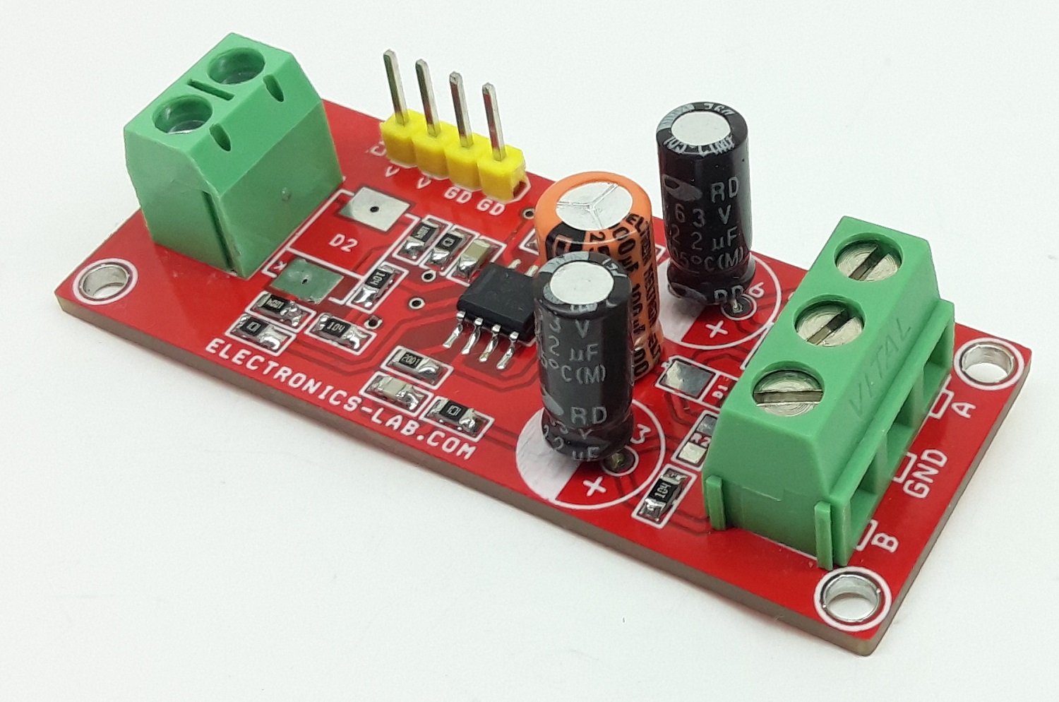
Electronics-Lab.com
The board presented here is a preamplifier for contact microphones that are used for amplifying the...
This is the purist approach solution to the tinny contact mic sound problem if you want the lowest electrical noise, or the lowest distortion at higher levels. Piezo mics aren’t usually considered …
glacial spruce
harsh gust
Amp circuit 1 https://www.electronics-lab.com/project/piezo-element-amplifier-fo...
They're basically both 10X gain as-is, but can be adjusted for more. However, that's pure voltage gain, and depending on the application, you may want current gain, transimpedance, or other behavior. Note that they also have some frequency dependent gain, that is the gain is not the same at all frequencies.
harsh gust
ohhh
harsh gust
glacial spruce
They're basically both 10X gain as-is, but can be adjusted for more. However, t...
I have worked on the second one (Richard's circuit) since last year and haven't been successful adjusting the gain boost (since there is no potentiometer knob in the original circuit)
I tried your idea first, it was not working well as I boost the gain, it sounded tinny and distorted both in the breadboard and perfboard.
So I asked Richard directly on that post, he commented that your approach is not recommended so I tried what he suggested, and the overall volume decreased, not increased.
I don't know if you remember my project, it's called Anthesizer, hearing an ant colony by installing piezo elements into their nests.
glacial spruce
I remember the project.
I'm curious why he doesn't recommend a potentiometer. Does he prefer fixed gain, or just doesn't want more than 10X gain?
"Tinny" usually refers to lack of low frequency response, there are ways to deal with that.
"Distorted" is more complicated, but often happens when you run into clipping.
harsh gust
 harsh gust
glacial spruce
"Tinny" usually refers to lack of low frequency response, there are ways to deal...
harsh gust
glacial spruce
"Tinny" usually refers to lack of low frequency response, there are ways to deal...
I do post production, dialog ediring, sound design. I can distinguish that kinda "tinny sound character with lack of low end" vs "something is seriously f###ed up" kinda tinny sound. It was latter.
Richard recommended me to replace R7 with 100k pot, which could only decrease the amplification, not increase.
this was his response to my answer
glacial spruce
Ah yes, that response. That doesn't make engineering sense to me, so either Richard or I (or both) are missing some important details.
harsh gust
hmm it could have been easier if I can summon you in my place but I can only wish
harsh gust
glacial spruce
Ah yes, that response. That doesn't make engineering sense to me, so either Ric...
oh and I just realized Circuit 1 is also lacking gain boost knob in its original circuit design smh
glacial spruce
You realize that if you told a sound engineer something was seriously messed up, she'd come right back with "messed up HOW? Crossover distortion? Intermodulation distortion? Phase distortion? Equalization problems? Hum pickup? Clipping? Asymmetry? WHAT?"
harsh gust
right
glacial spruce
Her next question would usually be "where in the signal chain does the problem show up?" And that question is pertinent to your problem too.
harsh gust
glacial spruce
Her next question would usually be "where in the signal chain does the problem s...
aha that makes sense. It is hard for me to figure that out for now. I am learning from basics these days though, how capacitor works, how diode works stuff like that

Part 2 The Actual Build: https://youtu.be/fXseAoSf2p8
This is a simple, very basic introduction to building a guitar overdrive using a breadboard. If you've ever been interested in building your own overdrive/distortion but didn't know where to start, this video is for you.
In this part 1 video we will take a look at the finished product and pl...

or would this be a better choice than amp circuit to boost the signal from piezo
glacial spruce
No, that circuit is designed to generate clipping distortion (by using diodes in the feedback loop of an op-amp). It would likely do the opposite of what you want.
harsh gust
aha, I got you.
glacial spruce
Learning the basics is slow going, but it will pay off
harsh gust
glacial spruce
Learning the basics is slow going, but it will pay off
you are totally right. I am having fun learning it, well it's reall hard but it's what it is.
btw, I am preparing for my next school exhibition, which is going to be held on Nov 12th this year.
I am thinking of using Daisy Seed to implement MaxMSP gen~ patch

but this time I really need that amp circuit to function properly to achieve my dream lol
harsh gust
I am thinking of using Daisy Seed to implement MaxMSP gen~ patch
glacial spruce
I don't know what any of that is
harsh gust
glacial spruce
I don't know what any of that is
Daisy Seed is a microcontroller that can load some audio processing software stuff.
For my previous exhibition, I had to just bump up the gain on my laptop without using the amplifier. But my goal is to make my exhibition independent from laptop
so my goal is to create "piezo-piezo amp-daisy seed-speaker amp- speaker" chain for each nest
and for my next exhibition, I am planning to use 4 nests combined all together like that
glacial spruce
You may need two stages of amplification between the piezo and the Daisy, but that should be doable if required.
harsh gust
glacial spruce
You may need two stages of amplification between the piezo and the Daisy, but th...
what do you mean by two stages of amplification? does that mean it requires two separate amplifier circuit between the piezo to Daisy?
 stable igloo
harsh gust
what do you mean by two stages of amplification? does that mean it requires two ...
stable igloo
harsh gust
what do you mean by two stages of amplification? does that mean it requires two ...
As someone with some audio background, I can answer that. Think of your piezo mic like an electric guitar with active pickups or electret condenser (ribbon mic would also be a good example). You need an initial mic amplifier to get the tiny signal up to something that conventional preamps can deal with. If the signal is not hot enough for the Daisy, you need something similar to a mic preamp AFTER the piezo amp to get up to line level.
harsh gust
stable igloo
As someone with some audio background, I can answer that. Think of your piezo mi...
oh god wait, ohhhh ok wait
so daisy's audio input is not gonna be the same as my apogee duet input
stable igloo
Daisy is equivalent to your laptop, in your use case, correct?
harsh gust
yes I guess so!
ohhh I am such a dumb perso n
I don't know why I have assumed Daisy's audio input would have all that audio to line level amplification thingy
So I might need sth like this right?

Features: 1, Small size, high power, no noise, portable. 2, Volume control potentiometer is convenient for user to adjust volume. 3, Wiring terminals allow to wire with only a screwdriver, not soldering iron. 4, Using high quality IC board, which helps a better performance of wiring. 5, Simple ci...
stable igloo
Think of the piezo amp as a part of your piezo mic, rather than a separate component in your signal chain. Like electrets, piezo mics and pickups tend to require amplification before they can be treated as a "regular" audio signal.
harsh gust
right
stable igloo
harsh gust
ohhh I am such a dumb perso n
No. Don't be calling yourself dumb. Audio is really weird in the electronics side and not always intuitive.
harsh gust
but in my previous exp, when I hooked up the piezo directly to my audio interface input, or to the random cheap guitar amp, it was pretty loud enough.
and when I was using piezo amp circuit I built, the gain was significantly lower, as if I am using an attenuator instead of amplifier.
ofc, there must be sth wrong with the amp circuit I built
stable igloo
harsh gust
but in my previous exp, when I hooked up the piezo directly to my audio interfac...
The audio interface will have a pretty beefy preamp in it and a guitar amp has two stages (preamp + power amp).
Piezo amps, in my experience, tend not to be terribly high gain. Their job is usually to give usable signal.
harsh gust
Maybe I might need that preamp and poweramp both. that would be really helpful for my use case.
I am picking up ants' sound with the piezo element
stable igloo
So, they likely compensate for the frequency response curve characteristics of the piezo mic/pickup.
Yeah. That sounds like a good course of action. You could probably play with a cheap LM386 board or the like after the piezo amp and get good enough signal.
Also, on the side of identifying "tinnyness" in your signal, you likely have a frequency analyzer tool in your DAW. That is extremely useful there as it will show if you're clipping at a particular frequency and give you a direction to go down for troubleshooting.
harsh gust
stable igloo
Also, on the side of identifying "tinnyness" in your signal, you likely have a f...
oh it's not even like that level of tinnyness. Ok, so it was basically distortion with faint response.
when the pot is in the lowest level, the amp was working normal just as the original circuit. But when I turn it up a tiny bit, it started going insane like that
I thought I def did something wrong I tried in different breadboard, different power supply, changed the opamp to new one, etc
but it was not working properly in my case.
Ok I googled a lil bit
Would this be a good try?

HiLetgo 5pcs LM386 Mono Audio Amplifier Module 200 Times AMP Solo 5V-12V 10K Adjustable
and using this one as mic level-to-line level amp
https://www.amazon.com/Universal-Mono-Pre-Amplifier-Kit-Intermediate/dp/B0002Z82XU/ref=asc_df_B0002Z82XU/?tag=hyprod-20&linkCode=df0&hvadid=644617763239&hvpos=&hvnetw=g&hvrand=6603306314332749532&hvpone=&hvptwo=&hvqmt=&hvdev=c&hvdvcmdl=&hvlocint=&hvlocphy=9031179&hvtargid=pla-430966926371&psc=1&gclid=CjwKCAjwp6CkBhB_EiwAlQVyxVxRgwgjcppP4YQH6vK75AEDE35N_t3vn6TmmoaEQmmtEb4sWz8TFhoCPhwQAvD_BwE

Velleman kit was developed as pre-module for a number of audio applications where the input signal is too weak. APPLICATIONS as a microphone pre-amplifier or for level correction. Power supply: 10-30vdc/10mA. Cable length: 50 cm.
And then it goes to Daisy Seed
https://www.electro-smith.com/daisy/daisy

Electro-Smith
New batch coming at the end of June! Daisy is an embedded platform for music. It features everything you need for creating high fidelity audio hardware devices. Just plug in a USB cable and start making sound! Programming the Daisy is a breeze with support for a number of languages including C++,
And this for speakers
https://www.amazon.com/PAM8406-Amplifier-Digital-Channel-Amplify/dp/B08RDN58SZ/ref=sr_1_9?crid=SYNAV91ETAC7&keywords=speaker+amp+circuit&qid=1686683498&sprefix=speaker+amp+ci%2Caps%2C697&sr=8-9

Features: Amplifier type can be connected to select functions. Type D for high power, type AB for low power, factory default is high power. External shutdown can be added, SD: the default is high power level, and at low power level, chip will shut down. MUTE: low level mute, factory default high...
stable igloo
That seems like it should likely do the trick, yes.
median hemlock
FWIW Getting a clean signal from a microphone/transducer is a rabbit hole that turns into an all consuming black hole. Frequency response, gain staging, noise rejection, etc. If things are off and you can’t figure out why, find an oscilloscope and trace the signal through all the parts. I love the idea of “Ant Music”.
harsh gust
I totally agree 200%
I have spent quite a lot of money on components and such for this.
harsh gust
median hemlock
FWIW Getting a clean signal from a microphone/transducer is a rabbit hole that t...
Thank you!
I will try with those for now I guess
stable iris
Is there a guide out there on what is legit and what is a scam in the audio field ? Might be a cynic but it all sound like scams nowadays. Especially when they pull out bandwidth as if singers sings 400x faster than in the 1980 and you need more bandwitch than about 200kb/s like on a rca cable
desert fog
The speed of the singing won't affect bandwidth.
Frequency content of the music will.
Also classical is some of the widest band music out there.
stable iris
but needing like 1000 mbps cables instead of 200kb/s like the old copper wires ?
I mean I assume the normal home user here not studios that must record on tape master with as much data as they can afford
What I often see sales people trying to sell which doesnt make sense to me is gold cables/power cord with a very high bandwidth at 20-100x the prices of normal rca cables
desert fog
That's just technology improvements.
desert fog
stable iris
What I often see sales people trying to sell which doesnt make sense to me is go...
Yeah that's just stupid.
stable iris
or it looks like an RCA cables but with "shielding" all over, sleeves of different materials (probably usually for the beauty of the cable(? 🤣 )) etc
desert fog
If you need the bandwidth (for instance in a studio with 48 audio channels from various microphones). Even then you'll have dedicated equipment for it, and gold coated cable won't make any difference.
The power cable also doesn't make much of a difference, although sometimes adding a ferrite bead can help.
stable iris
but wouldnt that need to be measured ?
Sounds like premature optimization like another field says
desert fog
stable iris
but wouldnt that need to be measured ?
Yes. Audiophiles are pretty insane.
But they somehow have a lot of money, and marketing is more than happy to sell them placebos.
stable iris
but I can safely ignore what most salespeople says unless they actually heard the sound system and measured something right so it's not based on pure air / speculation ?
stable iris
Im asking that because Im starting to consider getting 2 legit speakers that can connect to computer and other normal audio systems including ham/etc. But Im more familiar with studio stuff because I used to book for a friend and give them moral support when recording 🤣 But that studio stuff is way out of my price range and considering that if you get stuff like audiotechnika or sennheiser etc you probably pay half of it for the brand. So my approach would be more around finding what is inside / specs
desert fog
Not saying it isn't for the brand in this case, but a lot of the higher end companies are doing actual R&D work.
stable iris
but if you can aonly afford their entry level stuff do you still get these benfits ?
Im not an audiophile but Id often argue with my friend and his other friends about studio audio vs gaming speakers/headphones I saw nothing wrong and I remember hearing a world of difference between the two 🤣
desert fog
"Gaming" means that they dropped the quality into oblivion and added lots of 
stable iris
I mean just from seeing what is inside when it's not wireless (look like 1940 radio kits from popular electronics) I dont ever want to spend more than 30$ for them 🤣
In 90% of the case there isn't even a chip inside or anything related to improving the sound...
stable igloo
When it comes to headphones, sometimes you do get what you're paying for. For example, Beyerdynamic headphones are pretty pricy and do look on the inside like old radio kits but they are made in Germany and just about everything is replaceable by anyone who knows basic soldering and how to use a Phillips screwdriver. On top of that, they sound great and are incredibly comfortable.
Price-wise, a set of DT-990s cost about $160, which is about $8 in 1940.
Largely, if you're looking for good audio equipment, once you get to a baseline of quality, you hit a plateau of subjective characteristics, which are largely dependent upon your use case and potentially less clear cut stuff like preference and personal ethics (ex. I'm pro-labor, so, buy things that are ethically produced when I'm able to afford it).
stable iris
I meant stuff like most of the teardowns Ivee seen everyone uses the same small magnet no magtter if they arte 20$ or 200$ when tha magnet affect sound quality a lot in headphones. The board inside like about 2mmx2mm and seems to have no IC just directly connecting from the voltage line of the sound card without any filter/op-amp /dsp to make the sound better etc
the dt-990 pro I saw before seem to be quality stuff and I like the test points stuff (hurray for right to repair)
 desert fog
The test points are likely used during manufacturing.
stable iris
yeah but normally they hide them or epoxy over them
desert fog
Well if it's another manufacturing step it might not be worth the cost.
And they probably don't care that much.
stable igloo
Sometimes, simpler can be better. Though this is absolutely subjective. I prefer minimal processing, personally, so, I generally use a pretty flat pre and headphones that don't have any ICs that modify the signal. To me, they are a negative, when present. But, if you like your bass boosted, it's worth choosing something that sounds right.
The driver magnet type, size, and shape can indeed have a major impact on quality and color of the since produced. A good way to hear this in an exaggerated fashion is to listen to samples on the Jensen Loudspeakers website (guitar speakers). Neodymium magnets are very powerful for their size, so, they are typically smaller and lighter than AlNiCo for the same power. This influences how the speaker cover vibrates. Ceramic are pretty weak and inefficient, causing them to need to be much heavier for the same power. This also impacts the vibrations of the cone and gives a "vintage" color to the sound. AlNiCo are somewhere in between.
stable igloo
desert fog
And they probably don't care that much.
Yeah. It is something that the advertised in the past but I'm not sure how much of it is philosophy vs using a cost-saving measure for marketing. Either way, they're nicely repairable and modable.
stable iris
yeah maybe I have outdated knowledghe
but saw a coupl of videos and they seem to say they even got help from the company to repair it (but might have changed)
stable igloo
Yeah. Their support is pretty good from my experience.
For your use case, I'd definitely look at the specs for what your sound card can output and use that as your target. No point in getting speakers that can handle a bajillion kHz sample rate digital signal if your machine is just able to output 48kHz or 96kHz. I'd be surprised if there were a perceptible difference in most audio past a 96kHz sample rate.
When looking at interconnects (RCA, phono, SPDIF, TOS link), it's, like most audio stuff, very subjective. If the audio is just to be listened to, like music, any of them will work as well as the rest. If for video, you want to try to meet or beat the transmission speed of the video. If for games, I'd probably go with TOS link, if it is an option. This is because, while the digital signal does need to be decoded to create the analog signal to move the speaker, it is transmitted at the speed of light, which can help reduce perceived latency when syncing it with the video output.
Basically, I'd look at the specs of your source and destination, try to find a good fit, and try to get a listen in person because what sounds "right" to you might not for someone else.
Also, any frequency response advertised outside of the 20Hz to 20kHz range is pure marketing.
desert fog
stable igloo
Basically, I'd look at the specs of your source and destination, try to find a g...
Well, human hearing can go slightly beyond 20kHz (particularly in children). Also due to the inherent limitations of filters you don't necessarily want the cutoff to be exactly at 20kHz. 48kHz instead of the more common 44.1 is at least within reason. But generally you are correct.
glacial spruce
Right: while the advertised frequency response may exist, there is argument whether that capability has any audible (or other sensory) effect.
stable igloo
desert fog
Well, human hearing can go *slightly* beyond 20kHz (particularly in children). A...
Absolutely. My main point for frequency response is that typically high frequency hearing drops off pretty quickly with "normal" hearing damage accumulated with age.
Would be cool if we could readily get our own ears' frequency response charts in an objective manner.
glacial spruce
For good or ill, my hearing loss isn't "normal"
 young pawn
The MAX98357 says "Output Power: 3.2W at 4Ω, 10% THD, 1.8W at 8Ω, 10% THD, with 5V supply". https://www.adafruit.com/product/3006
Now, some speakers only say "4 Ohm" or "8 Ohm".
But for other speakers you can get these diagrams showing Frequency Response (red) and Impedance (blue). I notice that on "X Ohm" speakers "X Ohm" is just the minimum. And it goes up to >30 Ohm in one spot. 30 is obviously way more than 8. I'm just curious, what effect does that "high-ohm spot" have? Does it even have any effect? I guess it is already "calculated in" into the "1,8W at 8 Ohm" spec of the MAX98357

Listen to this good news - we now have an all in one digital audio amp breakout board that works incredibly well with the Raspberry Pi! If you're looking for an easy and low cost ...
glacial spruce
Yes, speakers have a "nominal" impedance, but it varies a lot due to mechanical resonances and the like.
Normally amplifiers have a low enough output impedance to keep control of the speaker, but it can have some effects on the sound.
young pawn
Thank you.
And directly affecting my project:
Just try the speaker out? Or is there a way to tell from the datasheet that for example a 30 ohm impedance at one frequency is definitely too high and will noticeably degrade the audio? I didn't find any such thing. So I think I will just try it out unless you stop me 😄
glacial spruce
Like I said, with a reasonable low-impedance amplifier (most are), it should be just fine. If you're building a custom cabinet, I'd avoid having a resonance at that frequency, as the amplifier will have less control over cone motion there, but otherwise it shouldn't be a problem unless you're going for extra sonic detail.
young pawn
Thank you 😄
 solemn frost
Hello all, i am working with a walkie talkie using arduino and nrf24, i am able to transmit audio successfully but I want to amplify the audio output. so i was looking for an amplifier circuit. there are 2 terminals for the speaker. if i connect the output to + of my speaker then where should i connect the - of the speaker. If i connect - of the speaker to ground, i dont listen anything. I am taking input from arduino's digital pins 9&10. This is my 1st audio project. Please help me.
 glacial spruce
That op-amp, while it can amplify, doesn't have much drive capability. I'd suggest using a speaker amplifier (LM386, PAM8302, etc.) for speaker driving duties.
solemn frost
Okay
harsh gust
I have several questions..!!
1> This is a pre-built preamp circuit I bought from Amazon. Is this the right way to connnect components?

2> This says Mono Amp but why does this have 2 inputs?

3> What would be the best way to power these 4 components efficiently?
 glacial spruce
harsh gust
2> This says Mono Amp but why does this have 2 inputs?
glacial spruce
harsh gust
2> This says Mono Amp but why does this have 2 inputs?
I think one of those is the output
harsh gust
glacial spruce
I think one of those is the output
omg you are right. I am so dumb
stable iris
why mono thought is stereo much much much more difficult ?
 tranquil sinew
Stereo is almost double the work as you need two amplifier channels and not always needed
 median obsidian
I have this old stylophone I built a year back
Lying in the cuboard
Not sure what the issue is
It's not working any ideas on how to test ?
Also how long to 9V BATTRIES last ?
glacial spruce
I'd reach for a voltmeter first and check some likely points. As for 9V battery life, there's shelf life, and life when plugged into something. For shelf life, it ranges from about a year (for the cheapest ones) to 10 years or so (for the fancy ones, or even more for the lithium ones, but those are uncommon). For a battery plugged into something, it depends on what the quiescent current draw is, but is generally fairly short, as 9V batteries simply do not have a lot of capacity.
median obsidian
OK ok got it working
I think the volume pot was having issues
And changed the 555 timer on the board
The batteries were showing 9.2V so I got worried on of the caps had leaked
The audio sounds super scratchy and weird tho
I feel this was always the case
Let me share the schematic along with this
median obsidian
glacial spruce
I'd reach for a voltmeter first and check some likely points. As for 9V battery...
Thanks for this
One of the batteries was totally dead and the other read 9v but didn't worm
Probably leaked somehow
 cinder briar
median obsidian
The audio sounds super scratchy and weird tho
I feel this was always the case
...
cinder briar
median obsidian
The audio sounds super scratchy and weird tho
I feel this was always the case
...
That might just be because of the sharp square wave
and also because you're moving the stylus
moving across a conductive surface will sound scratchy
median obsidian
cinder briar
moving across a conductive surface will sound scratchy
The actual styleophones use the same circuit but are able to felt a much cleaner more consistent sound.
Anything I can do to get it to their level ?
Also do you think it would be practical to add something like an arduino and have this interface with a computer ?
(Would also like to be able to power this with a USB connector instead of the current 9V battery set up
cinder briar
median obsidian
Also do you think it would be practical to add something like an arduino and hav...
Definitely possible with a midi interface over usb and some lower voltage circuitry
median obsidian
Would the arduino it self be able to do all this ?
cinder briar
Actually yes
Except for driving the speaker
But that just requires a simple amplifier circuit or module
glacial spruce
median obsidian
The actual styleophones use the same circuit but are able to felt a much cleaner...
You may need to do both mechanical work (get the PCB surface to make good reliable contact), and electronics (maybe some filtering)
 compact nexus
Can someone help me make this louder? Do I just need a bigger speaker? https://photos.app.goo.gl/UeAbLiLBqPiRFuNP8

I think I have it set to full volume in the code
young pawn
Is that a MAXsomething I2S DAC+Amp?
compact nexus
Ack I forget which one. Lemme check my purchase history
young pawn
lol I'm basically building the same thing currently. Except I want to play random tracks form an SD card that are like seagulls, ocean waves, sea shanties 😆
Except "I'm building [...] currently" = "I haven't actually started with the actual code." because I first had to make other people fix all the bugs in the I2S library (and fix some myself). Then fix the arduino-audio-tools RP2040 driver, and now I think I need to improve the performance of volume control 😆
compact nexus
Adafruit Audio FX Sound Board + 2x2W Amp - WAV/OGG Trigger -16MB PID: 2217
young pawn
Huh, not sure if my experience then applies. Still sharing it because maybe it's still useful as a comparison. I'm using one of these MAX98357A I2S amps. It's 3W with 4Ohm speaker. I'm using a 6cm 4 Ohm speaker and at full volume its way too loud. Like way louder than how I normally watch videos or listen to music
glacial spruce
compact nexus
Can someone help me make this louder? Do I just need a bigger speaker? https://p...
What impedance is your speaker? It could also be a sound level issue in your samples.
tall mango
What would be the best way to get a headphone-level audio signal from a feather? I noticed Adafruit no longer has the I2S headphone amp which I tried once and it was extremely loud (it might've been line level, but I'm not sure and can't find it now)
small niche
You could try the music wing https://www.adafruit.com/product/3357. I used it before and it didn't blow my headphones out.
tall mango
Just found that the same time you posted it lol, do you know if it can be used just as a DAC? (As in the feather just passes I2S or other audio data to it and it spits out the analog signal of it without decoding the mp3/wav/ogg itself)
Actually nevermind, I think I'll just use it for decoding too
glacial spruce
tall mango
What would be the best way to get a headphone-level audio signal from a feather?...
You can always make an attenuator to reduce the level
weary gyro
tall mango
What would be the best way to get a headphone-level audio signal from a feather?...
I really like these cheapie PCM5102A boards you can get from Amazon or Aliexpress pretty cheap. Not Feather form-factor but easy to wire up https://todbot.com/blog/2023/05/16/cheap-stereo-line-out-i2s-dac-for-circuitpython-arduino-synths/
tall mango
weary gyro
I really like these cheapie PCM5102A boards you can get from Amazon or Aliexpres...
Yeah that's what I was thinking of doing but I was worried it might be line level and blow my headphones out
glacial spruce
You can always add an L-pad, but most line level signals don't have the low impedance to drive headphones very loud.
weary gyro
tall mango
Yeah that's what I was thinking of doing but I was worried it might be line leve...
usually it's a problem the other way around: line level outs are not strong enough to drive the low-impedance of headphones. Headphones are usually around 16 to 600 ohms, while line level inputs have an impedance of around 100k ohms
In the case of the PCM5102 boards I've played with, they are strong enough to drive headphones (but I've only tried it with earpods and sony mdr7506s)
tall mango
Ok, I'll consider getting one then
random bone
interestingly, Pimoroni used to sell a Pi accessory that used this chip, but then discontinued it and now have PCM5100 one. I'm not sure why. Maybe there was a parts shortage of the '5102.
weary gyro
random bone
interestingly, Pimoroni used to sell a Pi accessory that used this chip, but the...
I am a big fan of Pimoroni's "Pico DV Demo Base", which also has a PCM5100A (not sure the difference between PCM5100A vs PCM5102A, they behave the same as far as I can tell). And Adafruit sells it! 🙂
Replying to myself: ah, the difference is in their dynamic range & noise. Not really an issue for most uses by us hackers
 glacial spruce
To get that full range and low noise, you'd need to use careful filtering and shielding anyway. If you're not doing that, it's not going to matter.
 gritty basin
What types of capacitors would you guys recommend for audio? I've read that PP generates less distortion then electrolytic, but others more generally recommend electrolytic, only thing I've seen people agree on is to stay away from mylar
Okay my options got chosen automatically, can only find electrolytics at 2200uf on tme
glacial spruce
Right, it depends on the value and use case. For large values, electrolytics are the way to go.
gritty basin
glacial spruce
Right, it depends on the value and use case. For large values, electrolytics ar...
Alright, now what properties should I be looking for in the hundreds of capacitors left unfiltered? Ripple, Leakage current etc
glacial spruce
It depends on the use case. For coupling capacitors, you want low leakage current and low distortion (I usually use film capacitors, but not always PP). For power supply filtering, you want low ESR and high ripple capacity, leakage isn't critical. For general purpose decoupling, it's not critical, I usually use ceramics in that position (but X7R or better dielectric).
desert fog
Mixing capacitor types and values can also be beneficial. Keep in mind that all capacitors behave like capacitors up to their self-resonance frequency, at which point the ESR and lead inductance will dominate.
 oblique radish
how i can measure speaker impedance with arduino or any other module
glacial spruce
Most speakers are fairly low impedance, which is tricky with an Arduino. Also, do you just want the DC impedance, or are you looking for something fancier like an impedance versus frequency sweep? There are some Arduino based component analyzers out there with an open source design, you could look at how they work for ideas.
oblique radish
glacial spruce
Most speakers are fairly low impedance, which is tricky with an Arduino. Also, ...
you are right , impedance vs frequency sweep analysis
glacial spruce
oblique radish
you are right , impedance vs frequency sweep analysis
An Arduino by itself would be fairly limited in the sort of analog analysis it can do, but with some outboard hardware, it could make a dandy controller. I had been thinking you could start with a DDS sine wave generator like AD9833 and some output measuring equipment, but a little looking around showed there are some chips like AD5933 that integrate a lot of the functionality of an entire network analyzer (even better than just an impedence sweeper). A web search for "AD5933 network analyzer" yields some ready built modules for under US$50 that would make building something like this much easier. There's an Arduino library available that includes examples for frequency sweeping https://github.com/mjmeli/arduino-ad5933 and the wiring is fairly easy, as it's an I2C controlled chip.
 drowsy parcel
can someone help me to fix something about adafruit breakout pdm mic? it
it is emerge
I am trying to convert buffer array to standard wav file to save voice with adafruit breakout pdm mic
i am using rp2040 with pdm mic
and also using circuitpython i do not know how to implement with c
glacial spruce
drowsy parcel
can someone help me to fix something about adafruit breakout pdm mic? it
it is e...
It's a pretty easy conversion, since the WAV format just stores raw sample values anyway, you just need to prepend a WAV header to it and emit the data.
drowsy parcel
okey
i am doing it already but there is problem about sample rate. when i take raw sample values to wav, i am choosig 16k sample rate which i choose but the sound which conversed is so fast. I mean if i record audio for 10 second, after conversion i got 2 second audio.
if i explain all of my algorithm from beginning
this my circuit python code:
GitHub
Sound recorder by Raspberry Pi Pico w Circuitpy. Contribute to newtonsgrandson/recorder_pico_circuitpy development by creating an account on GitHub.
it is basically record samples for 1 seconds and it stores in a sd card
i am recording samples as .npy format for 1 second
after that i unplugged my sdcard from my circuit then plug my computer
i am taking all .npy files
when i try to convert it to wav file, there is a problem about sample rate
my sample rate is 16k but when choose it into soundfile library which on my computer
the sound is faster than i record
i mean if i record 10 seconds it would be 2 second after convert it
when i find sample rate with try and fail, it is approximately 7.3khz
how can it be possible
glacial spruce
It could be the settings of your recording from the PDM microphone, or a bandwidth issue
drowsy parcel
it is same with documantation
sample_buffer_size = 200
sample_rate = 16000
mic = audiobusio.PDMIn(board.GP3, board.GP2, sample_rate=sample_rate, bit_depth=16)
young pawn
maybe a stereo vs mono issue?
drowsy parcel
when i choose mono
the sound is exploding
i can choose only stereo
i can send you
with wave.open('sine_wave.wav', 'w') as wav_file:
samplerate = 16000
nchannels = 2
sampwidth = 2
framerate = len(data)
nframes = 'NONE'
comptype = 'not compressed'
wav_file.setparams((nchannels, sampwidth, samplerate, framerate, nframes, comptype))
wav_file.writeframes(data)
do not use headphones
Write data to a wav file
with wave.open('sine_wave.wav', 'w') as wav_file:
samplerate = 16000
nchannels = 1
sampwidth = 2
framerate = len(data)
nframes = 'NONE'
comptype = 'not compressed'
wav_file.setparams((nchannels, sampwidth, samplerate, framerate, nframes, comptype))
wav_file.writeframes(data)
when i change nchannel to 1
with wave.open('sine_wave.wav', 'w') as wav_file:
samplerate = 7350
nchannels = 1
sampwidth = 2
framerate = len(data)
nframes = 'NONE'
comptype = 'not compressed'
wav_file.setparams((nchannels, sampwidth, samplerate, framerate, nframes, comptype))
wav_file.writeframes(data)
when i choose sample rate to 7350
it is more clear
solemn flint
I don't know this library, but setting "framerate" to the length of the data looks suspicious at first glance.
drowsy parcel
okey i will be focused on it
i changed it to possible values like buffer size 200 or sample rate but result is samew
same*
solemn flint
drowsy parcel
i changed it to possible values like buffer size 200 or sample rate but result i...
I think you might have a wrong order of parameters in the setparams call. I'm not 100% sure what library you're using, but one reference suggests that it takes:nchannels, sampwidth, framerate, nframes, comptype, compnameSo you may want to double-check the library docs there to make sure the parameters are what you think they are.
Actually they may be correct, just named weird. You have nframes = 'NONE', but that's being passed in as the slot for the comptype parameter, so it makes sense for that, for instance. And the original len(data) would work for nframes, but you just had that parameter labeled as framerate instead, etc.
drowsy parcel
okey i will check parameters and i will tell you the result.
i am using 'wave' library at this time
btw
but just i wanted to highlight something. when i change the sample rate, the length of sound is changing also. sample rate should be number of samples for a time. So, when i use a sample rate which i used in microcontroller, it should be same. Because
because it is constant you know. I did not understand this topic. I think i had a mistake on my algortihm on raspberry pi pico software
am i wrong?
there is a problem on sample recording
but also there is thing that i should tell you, there is not lost on sound which i recorded. It is full at the begining until end
is there a auto decimation step when i record samples on my sdcard xd
i will return when i will check my parameters on wave library thanks
 twin compass
Hello! Does anyone here know a way to connect the audio output from my Soundboks 3 speaker via a 3,5mm audio cable to my esp32? I would like to read the audio signal of what is currently playing through the speaker, but realized after just plugging the Tip Ring and Sleve directly into the esp32 that the signal was not what I expected. Haven’t quite figured out entirely what comes out from each of the connection points other than that the tip and ring is often right and left channel respectively, oscillating around 0V, so it goes to negative voltages which as I understand the ADC does not support.
tall mango
I just got a used 7" reel to reel player/recorder, and I'm trying to figure out ways to get rid of the large amounts of noise. I suspect the tape I'm using is a little older and therefore noisy due to being written to so much. I also wanted to get a demagnetizer to demagnetize my tape heads, but they're rather expensive for a tool I'll use probably only a few times. Is there a way I can DIY a demagnetizer without damaging my tape heads?
Here's an example, the first photo is a snippet of the audio I recorded onto the tape, and the second is the same section but recorded back onto my computer. There's also not very great fidelity in the mids and highs.


I did test another tape by the way, and while it had less noise it was still somewhat present.
random bone
tall mango
I just got a used 7" reel to reel player/recorder, and I'm trying to figure out ...
The noise could be coming from the tape deck, not necessarily the tape. If you have some spare tape, you might try a fresh recording, and then playing it back. Or if you have a friend with a tape deck, try the tapes.
tall mango
I only have two rolls of tape, and they're pretty old (one of them I'm estimating was recorded in the 70s) but I plan to buy a new reel today.
random bone
sounds good
unborn drum
That’s really weird noise to see on the spectrogram. It’s so even and broadband. Makes me wonder if something else is going on in the signal path
tall mango
I also did some careful cleaning of the tape heads with some alcohol and qtips but it didn't make much of a difference.
tall mango
unborn drum
That’s really weird noise to see on the spectrogram. It’s so even and broadband....
Not sure, I have my graph set to linear so maybe thats why?
unborn drum
Could you upload audio clips?
tall mango
Yeah one sec
random bone
if you could generate sine wave or something similar and then record and play it back, that would also be informative
you can do that in Audacity
tall mango
Yeah I did that with the last tape deck I had but I will do it with this one too later
tall mango
unborn drum
Could you upload audio clips?
Ill record the sine wave once the motors cool down (it doesnt have any cooling so I assume its normal??)
random bone
maybe record a long chirp too to check the frequency response
tall mango
Would a frequency sweep work better? I made a test signal that goes from 60Hz to 22050Hz over the course of ten seconds.
unborn drum
Interesting. Sounds like tape hiss alright. New tape may be the answer. How are your audio levels? If you have room, you could turn the level up, and the underlying hiss will be lower.
Also what speed are you at?
tall mango
The hiss gets louder with the volume level so I don't think its the amplifier or anything like that. Probably the tape or tape heads.
tall mango
unborn drum
Also what speed are you at?
7.5, can't remember what unit that would be in.
unborn drum
tall mango
The hiss gets louder with the volume level so I don't think its the amplifier or...
Does this reference to the signal going into the recorder, or the signal coming out of the recorder?
tall mango
The hiss comes from the tape deck line out, which is what im recording from
random bone
if you are not playing, do you mean there's residual hiss?
tall mango
Theres a little hiss when its not playing, but it gets a lot louder when playing
random bone
tape hiss is an inherent thing (https://en.wikipedia.org/wiki/Tape_hiss) . All kinds of things were invented to get around it: the original DOlby products, for instance
tall mango
Also heres the results from the sine and frequency response test (it has some annoyingly high pitch sounds so be careful)
Seems like it struggles with higher frequencies but it can still do it
random bone
yeah, that just sounds like tape hiss to me. Does the tape deck have any noise reduction circuitry like Dolby?
are you recording at 3 3/4 or 7 1/2 ips?
tall mango
Im not sure, this ones old but I can check the maintenance booklet
tall mango
random bone
are you recording at 3 3/4 or 7 1/2 ips?
7 1/2
random bone
it would be on the panel; it would be things you can turn on and off
there would be Dolby button, etc.
tall mango
Oh, then no
random bone
what is the brand and model?
tall mango
EICO RP100
random bone
a lot of the noise reduction stuff was invented to make cassette tapes palatable at all: Dolby, fancy tape forumlations, etc.
EICO is not a high end brand. This is tubes, right? Tubes can get noisy. But frankly, this sounds like the tape decks I encountered in the 60's as a kid
tall mango
I think it does use tubes
random bone
note https://reel-reel.com/tape-recorder/eico-rp-100/ "Sound quality: 5/10". There will be some noise from the circuitry, the frequency response maybe could be better, etc.
you are not going to get CD quality out of this
random bone
fancy reel-to-reel decks used for mastering at that time used higher tape speeds
tape hiss comes with the territory
you can record at as high a level as possible without flat-topping. The more signal the less hiss
browse around in https://audiokarma.org/ and < https://gearspace.com and read people's experiences. You can touch up the deck. But it's not going be what you're used to, no matter what. ... I've lived through this. CD's and digital audio are a big improvement over what came before, despite the current fascination with vinyl
tall mango
Unfortunately, I'm stuck with 7 1/2 ips. At least until I can get a reel to reel that's more reliable.
random bone
My father used to record the concerts of our local amateur orchestra. I would operate the tape deck. We also recorded TV programs off the air, etc. He had a reasonable deck. there was hiss
what is your goal, or is it just to fool around?
tall mango
At least it was like $10, the guy said it didn't work but it works just fine. Unless "works" means good quality.
tall mango
random bone
what is your goal, or is it just to fool around?
I'm just hoping to get more comfortable with analog stuff, I had a couple ideas for projects involving pure analog audio and it requires a way to record the signal.
I've been familiar with vinyl and regular audiocassettes for a while but never really focused on tapes as much.
random bone
and not record it digitally and go back to analog?
unborn drum
Do the meters on the front of the recorder work?
tall mango
I don't think so
unborn drum
How are you setting the level?
tall mango
I tuned it until the signal was just about the same as my original audio clip but through the DAC
unborn drum
“It” being? A gain knob on the recorder?
So the setup is DAC-> Tape and then Tape -> DAC?
 tall mango
So I'm feeding a line level signal from a DAC connected to my computer into the line in port on the tape deck, then playing the recording back through my ADC connected to my laptop.
unborn drum
random bone
Omg thank you. I’ve been staring at blurry jpgs lol
Can we see your machine? 🙂
 unborn drum
Looks lovely! Those knobs are something else, huh?
Are the mic levels down for both channels?
tall mango
Yes
unborn drum
And on the PLAY SEL knob, the eq is 7.5?
tall mango
Oh, no, it was set to TK1
The only tape I have is mono
The knob doesn't actually turn past TK2
unborn drum
Is that for the upper part of the knob or lower part?
tall mango
The upper part, the lower part doesn't move
unborn drum
Huh. Is it stuck? It’s label seems to indicate that the lower part selects the eq
tall mango
Oh I think the knob was misaligned
Nevermind yeah the knob is a little stuck
Should I add oil to it?
unborn drum
Eh, I can’t answer that one! If it were me, I’d keep trying to wiggle it. Also I was just looking at the meters, and their labels begin at -7db. That’s really pretty high. If your signal is low, you might not see them moving.
I still have this suspicion that the tape can handle more volume than you’re giving it. So, try turning up the laptop or turning up the LINE LEV knob and turning down the level on the ADC in. See if you can get those meters to move at all before the tape distortion becomes audible.
If you’re recording as hot as possible and still have that hiss, it may be inherent to the machine.
tall mango
I turned it too much and the indents on the knob that turn the potentiometer actually just broke... oops
unborn drum
Drat!
tall mango
I might be able to find some pliers to loosen the potentiometer to the point where it isnt as stuck anymore
random bone
which knob are we talking about?
tall mango
play sel
random bone
i think the the upper knob has only four positions. The lower knob is the EQ selection on the right, at 1 o'clock and 2 o'clock ?
(I looked for a manul for this but they are all for-pay downloads)
tall mango
Oh, i think youre right
random bone
is the EQ part of PLAY SEL (the lower knob) a two position switch or a potentiometer?
tall mango
I tried maxing out my volume on everything and it did some weird stuff to the frequencies

I do notice less noise though
random bone
the way to set the level is to feed the signal and then adjust the LINE LEV knobs to keep the level just below something (maybe 0db here??)
did you see the meters move at the higher level?
I can't tell if there are red markings on the meter, but below that
unborn drum
The traditional calibration level is -20db in digital to 0db analog
tall mango
Oh, I forgot to check the meters
unborn drum
Assuming they work 😉
tall mango
Yeah, the meters won't budge
random bone
if you adjust the LINE LEV controls does it make any difference? They're not moving at all?
tall mango
Yeah, even all the way up
random bone
are the meters completely immobile? I've had very old meters get stuck: sometimes they are dirty. Unfortunately I cannot find any schematics for this to theorize on what might be going on. If you have the equipment you could measure voltage at the meter and see if it's varying.
but having both not move is suspicious...
tall mango
I would, but sadly my multimeter battery is toast and I don't have any extra 9Vs
Also I just looked at the back of the machine, theres bias adjust and meter adjust knobs. Maybe that's the issue?
unborn drum
It’s also not clear what those meters measure. Signal going to record head? Signal coming from play head?
unborn drum
tall mango
Also I just looked at the back of the machine, theres bias adjust and meter adju...
Worth a shot!
Bias seems fine based on your screenshot
tall mango
No difference :(
I turned the knob all the way clockwise and counter-clockwise and it stayed at the bottom
Maybe whoever assembled this missed something
random bone
take a picture or mark the current settings of the meter adjust knobs 🙂
tall mango
I set it back to what it was before
unborn drum
Bummer. I agree with danh that they could be stuck.
Also like danh i’m old enough to remember tape, and I think this level of hiss is within the realm of normal for pre-Dolby home recorders
glacial spruce
For physical reasons involving tape speed, particle size, head gap, etc., there's a roll-off of higher frequencies, along with some intrinsic hiss. Some equalization schemes try to recover the higher frequencies, but tend to boost the hiss (which is mostly higher frequencies) in the process. The Dolby ones use a pre-emphasis/de-emphasis technique to minimize this, and can work pretty well, but only when things are properly adjusted.
random bone
tall mango
I set it back to what it was before
i don't know if the meter covers would snap off, but I would be very careful. A service manual would be very helpful. You might ask in the forums I posted above if anyone can give guidance. It's a project and a learning experience! And if this one doesn't work out, another one might.
tall mango
It actually came with the instruction booklet and assembly booklet
random bone
tall mango
It actually came with the instruction booklet and assembly booklet
oh fantastic!!
the schematic may have voltage readings at various points
tall mango
Yeah, but I have no way to read them right now sadly
random bone

Stuck VU meters are an occasional problem in vintage audio gear, here is how I usually go about fixing them.
tall mango
Unless I can find that other multimeter
random bone
time to sleep on it, maybe. this is a multi-day or night project
same idea as video: lots of search results for "stuck vu meter"
glacial spruce
Thanks for those pointers, I have a stuck meter for which it would be difficult to source a replacement, so if I can unstick it, that would be helpful.
random bone
i have a dual-pointer SWR meter with one sluggish pointer. this may give me some ideas
glacial spruce
Oh yeah, those dual meters are presumably speciality items too
random bone
fer sure: it's a quality Daiwa meter, but it's 40 yo
random bone
glacial spruce
Thanks for those pointers, I have a stuck meter for which it would be difficult ...
i did turn the center "screw" on one of the movements on my Daiwa meter, and maybe it loosened it a bit. But equally important was that there was a static charge on the printed meter face under the plastic cover. Moving anything (tools, fingers) near the face affected both pointers. Blowing breath on it to add moisture did not help, but a a wipe with a dryer sheet cleared up the charge completely. I also wiped and cleaned the outer protective face And this is with ambient humidity about 50%. Then tested with another SWR meter in line, and it's looking good.
glacial spruce
Nice! That static can really mess with sensitive meters.
If you didn't see it, you might enjoy this writeup of a baffling/amusing incident I had with an analog meter a while back #help-with-projects message
random bone
glacial spruce
Nice! That static can really mess with sensitive meters.
Ha! I did not see that. My father is very possessive of his Triplett 630
glacial spruce
Those are workhorses too.
tall mango
I'm looking for some tape to get for my reel to reel, and I don't want to spend too much on really nice mastering quality tape because it's not a very high end machine. Would it be okay to get some old stock tape from eBay? I mean from around the 1960-70s, or would it have degraded by now?
My mom used to work with tape at the radio station she worked at and she's worried the tape might be brittle and unusable by now.
oblique radish
glacial spruce
An Arduino by itself would be fairly limited in the sort of analog analysis it c...
AD5933 is capable of measuring impedance from 100ohm but my test speaker is 4ohm.
desert fog
It's 4 ohms at DC, right? Speakers are mostly inductive, so by the time you reach into the kHz it likely has considerably higher impedance.
oblique radish
found this circuit, it is hard to found out lmc6482. can i use 2 lm358 for the circuit?
 desert fog
Probably not, but I'd have to read through the datasheets, and I'm not going to do that from my phone.
oblique radish
desert fog
It's 4 ohms at DC, right? Speakers are mostly inductive, so by the time you reac...
purchased a meter when ever do sweep analysis, we have to wait for long time to measure impedance. 4ohm speaker show more than 12ohm
oblique radish
desert fog
Probably not, but I'd have to read through the datasheets, and I'm not going to ...
i too using ad9833 and op177 to generate the wave with arduino as controller
oblique radish
desert fog
Probably not, but I'd have to read through the datasheets, and I'm not going to ...
is ter any way to measure impedance using arduino or rp2040 ?
specs of test speaker.
 glacial spruce
In any case, you'll need some additional circuitry
desert fog
As madbodger said, not directly.
Also, impedance is not a single value. It's a frequency-dependent curve. When you see a single number describing impedance, that value only applies at a single frequency (or within a band of frequencies).
glacial spruce
Right, they want to know how to do an impedance vs frequency sweep
oblique radish
glacial spruce
Right, they want to know how to do an impedance vs frequency sweep
correct so that i can get all parameters of speaker.

Using a half-wave rectifier circuit and Ohms Law to calculate Loudspeaker Impedance with Arduino.
Disclaimer: If you use a Smartphone, you are doing so at your own risks.
The schematic, BOM, Excel sweep examples, DATS' examples and Arduino sketch can be found at:
https://drive.google.com/drive/folders/14WBl1iEWIA8lTX7vHqwqvgWsmDyHNxlp?usp=sh...
drowsy parcel
hey, can someone explain my how to get binary data from my PDM Mic with circuit python as shown below?

I am trying to make a PCM to PDM process from scratch
glacial spruce
Hopefully CircuitPython includes functions to do this sort of thing, as native Python isn't particularly good at bitwise manipulations itself. Maybe ask in #help-with-circuitpython ?
random bone
drowsy parcel
hey, can someone explain my how to get binary data from my PDM Mic with circuit ...
unborn drum
tall mango
My mom used to work with tape at the radio station she worked at and she's worri...
I think this often depends on storage conditions. My last job using my reel to reel was digitizing some ancient UNICEF radio tapes. They had been properly stored since the 50’s and 60’s and the tape was in fine shape.
You could also look into baking your tape. Like, in the oven: https://www.radioworld.com/industry/baking-magnetic-recording-tape#:~:text=Place the tape in a,to working with the tapes.

Radio World
Baking Magnetic Recording Tape Jan 7, 2002 12:00 PM Over time, magnetic recording tape becomes unplayable because the binder used to adhere the magnetic material to the backing or a chemical added to the binder becomes unstable. Tapes in this condition will leave a gooey residue on the tape transport. This residue is comprised mostly […]
oblique radish


@glacial spruce @desert fog
used ad9833 for generating sinewave of 300Hz and sweep 20Hz - 20000Hz. can find impedance
desert fog
Nice!
drowsy parcel
random bone
See <https://docs.circuitpython.org/en/latest/shared-bindings/audiobusio/index.h...
this class gave me only 32K values. When i decode this vaue, w
will i take the binary datas?
glacial spruce
Presumably it would be binary data
desert fog
Those would just be signed 16 bit integers.
drowsy parcel
i understood but it does not look prety true, logically i mean. if i show you the values of which i take from PDMIn class: array('H', [33297, 33288, 33298, 33307, 33270, 33290, 33294, 33294, 33342, 33373, 33327, 33279, 33265, 33283, 33293, 33260, 33415, 33300, 33167, 33299]) and its just first 20 values. their mean aproximantely 32K when i convert it to wav file it gave really bad sound only
and i develop simple algorithm for that
but it is not also effective
if i tell you my algorithm: 1. take samples mean 2. subtract mean from all sample's value 3. map every sample array to 32K again 4. convert wav data
i mean by 3. step map every data between -32k to 32k
let's say before process if data looks like that: [33297, 33288, 33298, 33307, 33270, 33290, 33294, 33294, 33342, 33373, 33327, 33279, 33265, 33283, 33293, 33260, 33415, 33300, 33167, 33299] after process: [ 4540 2792 874 1172 2195 -1215 1726 -1343 191 1385 2067 -362
1385 -447 405 -1428 2792 -1726 -106 788]
after that process sound can be understandable but it is not clear at all
what do you prefer for me pls, i need so much help
random bone
drowsy parcel
if i tell you my algorithm: 1. take samples mean 2. subtract mean from all sampl...
yup, this is what we do. Also, which board are you doing this on? On some boards (SAMD21, e.g.), the filtering is done "by hand", and the filter is very simple and not very good (low bit rate and weak rolloff), because we don't have the CPU time to do a better filter.
drowsy parcel
random bone
yup, this is what we do. Also, which board are you doing this on? On some boards...
Pico W
what do you prefer for me, my job is record with pdm mic and save it to sd card as sound file
which path i should fallow
random bone
drowsy parcel
what do you prefer for me, my job is record with pdm mic and save it to sd card ...
you cannot record more than a few seconds at a time, because we don't have batch PDMIn (There is analogbufio for boards with a DAC, but that's not true on the RP2040).
this is not something the CircuitPython is very good at
due to hardware limitations
the sample to record has to fit in RAM, and then there will be an interruption while you write it out
drowsy parcel
yes, i meet with this trouble. I just recorded samples as .npy file in ulab's numpy and i just limited with 1 second
for example, i record 10 seconds as 10 ".npy" files
random bone
we don't have I2SIn. If we did I would be recommending an I2S input mechanism
drowsy parcel
so, sir can i record sound's as 1 second file
it is also suit for me
i can merge them after process
just i need clear and understandable sound
https://www.youtube.com/watch?v=5lH-tQw0tlU i wanted to fallow these steps but i was confused how i can get the pdm data by PDMIn class
Find out more information: http://bit.ly/AN5027-AppNote
http://www.st.com/memsmics
http://www.st.com/STM32
The STM32 Microphone Audio Acquisition video series is intended to provide information, suggestions and practical solutions for interfacing with PDM digital MEMS microphones using STM32 microcontrollers.
Starting from the general concepts...
because it does not look like true, logically i mean. just 33K values.
random bone
around 32k is the zero-crossing point, so you have to remove the DC bias to center it around zero. That is what you are doing already.
random bone
try recording silence vs a loud noise
drowsy parcel
okey i will try and observe
now i want to ask a last question. should i subtract samples with 32767?
random bone
this is the C code, with the decimation and simple filter: https://github.com/adafruit/circuitpython/blob/main/ports/raspberrypi/common-hal/audiobusio/PDMIn.c
drowsy parcel
to remnove the dc bias