#help-with-3dprinting
1 messages · Page 8 of 1
 placid grail
Already I feel uncomfortable because I have to hold the tower thing by the big metal threads to screw it in 😦
seems less fragile than the rubber belt
I mean the "gentry frame" as they call it
already stuck 😦 theres a ribbon cable in the way of the screws. manual dont mention it neither does assembly video
 karmic brook
You don't see that much in the US, where washers are generally 120V and dryers are generally 240V. Although I do have a 240V European style washer, it still has a separate circuit and outlet.

 balmy pulsar
most dryer are 240 but in condos they have little 120 models. horrible things dont dry anything.
placid grail
mine are 240V but dont remember if 3 or 4 prongs
Also the wall behind me has an orange light in it
but not sure why/how
Had to get used to it when I first moved in I thought there was a fire in the wall but it didnt flicker
karmic brook
Huh, I have an orange light too, not sure if it's an indicator, night light, or what.
placid grail
Its behind the switch with a potentiometer for the brightness of my kitchen hanging ceiling lamp
when it's dark I can see it clearly behind the switch a bit below it in the wall
grrrrr that latch

by the instructions Im supposed to align the gentry perfectly or the 3d printing will not work
but there is a fixed static ribbon cable in the way
in the video for assembly theres no such latch with the cable in it the cable is affixed to the top near the nozzle. But for me it's embedded under the 3d printer and throught that latch
karmic brook
The cable looks flexible to me. My printer (different brand) does a calibration step to see how square it is. It'll adapt if it's a few degrees out, but I managed to assemble it square.
placid grail
but under the printer its not
everytime I turn the screw next to it and I can hear it rip
that is what stress me out ripping the cable it the sleeve
let me get a pic

I dont have any videos/manual section that says the cable can be slided off and freed at the bottom. if it rips Ill possibly have to order just that part and place it inside at the bottom
Found an end user with an unboxing video that seems as perpexled as me about it 🤣
Seems to like they removed the metal panel to understand it better as they are more comfortable than me with disassembling expensive electronics but it shows that ribbon cable thing much better

I guess if it all fails it will just take longer
since it is moddable and the board/firmware is supposedly "open-source" etc
"ZNP Robin Nano v1.2 is a powerful 32-bit 3D printer control board with STM32F103VET6. Support Marlin2.0. Support ZNP Robin TFT35 V1.0 touch Screens. The mainboard integrates 5 AXIS interface, hot bed, heating head, 3 NTC100K, 1 MAX31855.The motherboard integrates After shutdown. Support MKS Robin WIFI for cloud printing and supports firmware upd" with firmware code on github, pinsouts etc
placid grail
3d printer seems to be working
havent printed yet it's self-calibrating atm
(It is also making me used to it, like it's close to my smoke alarm and a/c unit with 71oF air coming in)
 dire lichen
Considering using a prusa MK4 (or similar) for manufacturing casings for a saleable product - any big no-nos to doing this/considerations?
 keen raft
dire lichen
Considering using a prusa MK4 (or similar) for manufacturing casings for a salea...
keen raft
dire lichen
Considering using a prusa MK4 (or similar) for manufacturing casings for a salea...
Not really printing related advice, but printed stuff looks and feels "homemade" and that may lower the perceived value of a product, especially if it's not known to the buyer up front, so the quality needs to be flawless. Choice of filament also plays into this.
dire lichen
Thanks
placid grail
instructions for calibration says to push the nozzle in the bed unless there is friction between it and a piece of paper
From -1.2mm to -1.4mm there is a little bit of friction At -1.5mm there is a bit of friction (vs little bit before).
What setting do you guys think I should use ?
please give me your thoughts about this before a bad leveling can screw everything up
 vivid helm
I would stay in the 1.2-1.4 range.
placid grail
it's minus 1.2mm to 1.4mm like the factory 0 is 1.2 to 1.4mm too high
The 2nd step after bed level calibration has me manually inputing a z-axis compensation: "place a A4 paper between the nozzle and the platform. Click the compensation value and continuously push and pull the A4 paper. Compensation levelinng is completed when there is friction force"
vivid helm
Yeah, so what you're doing is probing the bed height and flatness. It's ok for the nozzle to touch as long as it doesn't smash down onto the bed. In normal use it won't go that low.
placid grail
videos from 3d printing veterans said to do until there is a slight slight friction so I set it at -1.35mm
bed stay hot after calibraiton not sure why. I guess Im supposed to do a test print or something. Im not really understanding so far how am I supposed to bring a file to the printer hehehe
This is my very first time 3d printing by the way. Never had any class on it or watched any video (except the ones for setupping my current printer)
placid grail
something is happening after I touched print - hope the very small roll of PLA that cames with it is enough for the test print
 faint sky
It's not for your printer but the general idea is the same for any bed slinger https://www.youtube.com/watch?v=_Ic00W18_ck

Are you struggling to get a good first layer? This can be the first problem beginners come across. There are many tutorials for how to level your bed. Many of them leave you with more adjustments still to do afterwards. This simple method will give you a near perfect first layer within minutes on any 3d printer.
..................................
placid grail
After factory settings/initial auto-calibration: Anything glaringly wrong besides the z-axis I should adjust by 1mm up to have enough extrusion and the grating texture in the front (but not sure if that is part of the model) ??

Im going to print the boat thing as well to adjust etc
placid grail
heheheh what a mess 😦 It left the printing bed during printing not sure why. Is it normal for the first layer to be so thin ?

But 80% fill rate seems to make those beams pretty solid
faint sky
bring z-offset down a hair, the spaces in between the brim of the figure means there's not enough squish. those lines should be connected, shouldn't be able to see spaces between them.
i'm surprised the figure printed that well... or at all. kind of an accomplishment in itself.
placid grail
the first layer isnt there if that is what brim/squish mean. Im trying now with a raft line first layer and adjusted height up by 0.2mm. the annoying thing is the spiral of filament inside the holes when those holes should be clear
let me grab the model (also I rescaled it to fit an M3 a bit better)
 placid grail
it is still putting strands into the screws holes..
 faint sky
if it's a raft then yes those spaces might appear between the lines. generally you'd want a brim for better 1st layer to bed surface adhesion but with a part that makes a large amount of surface contact like yours then a raft or brim should be unnecessary.
unsure what would cause something like that other than poor retraction but the rest of your part looks good. :/
faint sky
look into e-step calibration
 vocal flax
dire lichen
Considering using a prusa MK4 (or similar) for manufacturing casings for a salea...
vocal flax
dire lichen
Considering using a prusa MK4 (or similar) for manufacturing casings for a salea...
Sealing is no no for most filaments. I think only pet type (pet and petg) can seal but then it's still not guaranteed.
vocal flax
keen raft
Not really printing related advice, but printed stuff looks and feels "homemade"...
I one up this comment and add you can get 3d printed enclosures sanded and painted by some companies and result is just as good looking as injection molds
vocal flax
placid grail
it is still putting strands into the screws holes..
Either pressure advance (k value) or retraction is not fully on point
placid grail
meh it's not like I have control of these on my slice.r.. 😦
but Ill try with another first layer I guess / use the glue stick
boat didnt work the piece left the bed during print and it made a wool ball of filament so adhesion is really a problem
I think that there is filament inside because the slicer gets confused because of the screws threads inside the holes
or something
vocal flax
placid grail
meh it's not like I have control of these on my slice.r.. 😦
Retraction generally handled in slicer, and pressure advance constant can be controlled by gcode but idk slicers implement it
vocal flax
placid grail
boat didnt work the piece left the bed during print and it made a wool ball of f...
Make sure bed is clean. Did you wash the bed after the setup?
placid grail
no, seemed clean off the factory ? I bet Ill need some special products to clean it ?
something weird is that elegoo seems to be using a custom build of ultimaker that is at version 4.8.0 but normal ultimaker is at 5.3.0
the version on elegoo website is still 4.8.0 so since it's a custom build Im not sure if I can use the generic one (or another slicer at all)
keen raft
placid grail
the version on elegoo website is still 4.8.0 so since it's a custom build Im not...
You can basically use any slicer you want, you just have to set a few options correctly (print bed size and origin, nozzle diameter, etc.), otherwise the commands generated by the slicer won't give you the expected result.
placid grail
These are the options I have, so far I tried turning off fan cooling and setting retraction to 3mm. Using raft or brim first layer. 80% fill seems perfect to get solid construction part (tested it with an hammer and tested screwing metal screws in and bending it etc and it's really really good)

it also change to lines type of print, maybe I should try triangles ?
keen raft
placid grail
it is still putting strands into the screws holes..
What does it look like if you keep printing this?
placid grail
well let me print it a second time it will take around 1h. The problem is mostly the other type of pieces like the benchy that is supposed to be pre-sliced etc
I can live with some strings inside the screw holes for the construction pieces 🤣
I could try to print another part of the construction kit that takes like 2 minute to print if you want me to run tests
keen raft
placid grail
well let me print it a second time it will take around 1h. The problem is mostly...
I'm asking because looking at the CAD screenshot further up and depending on the dimensions, printing it in this orientation may require supports and they aren't visible in the picture. Looking at the underside should look fairly stringy in that case (once you've removed the raft)
keen raft
placid grail
I could try to print another part of the construction kit that takes like 2 minu...
If your slicer or CAD software have the option, cut a small section from your model and print only that, if you need to test things. If a piece of the model with one hole prints successfully, so will the rest, most likely.
placid grail
keen raft
I'm asking because looking at the CAD screenshot further up and depending on the...
are you saying the strings under the screws holes happens because of the raft ? And the dimensions are 96mmx12mmx12mm
The goal was to test the toughness as well that is why I went for the full piece. But I guess Ill do the tests with the 1 hole piece from now on
keen raft
placid grail
are you saying the strings under the screws holes happens because of the raft ? ...
No, I'm saying that with few exceptions, every extrusion the printer makes needs to be on top of something. Printing in midair is very hard 😉
In this screenshot, supports seem to be turned off. Looks like Cura though, I don't use that myself, so I'm not sure how significant this setting is at this location.
 vocal flax
placid grail
no, seemed clean off the factory ? I bet Ill need some special products to clean...
vocal flax
placid grail
no, seemed clean off the factory ? I bet Ill need some special products to clean...
Dish soap generally safe to use
Alcohol is popular but I've heard in some conditions it might dissolve pei
placid grail
I dont really understand the support thing to be honest or what they mean by overhang
from what you are saying it seems since there is around 3mm under and over the screws holes it might be an overhang ??
even thought it connect on the x-y axis just not the z one(height). I thought if I added supports I would have to saw it off or something
also: there's going some delay because Im on call and my clients seems to be having many problems today
vivid helm
placid grail
I dont really understand the support thing to be honest or what they mean by ove...
Overhang = printing at an angle up from the bed.
Bridging is when you are printing over open air
keen raft
placid grail
I dont really understand the support thing to be honest or what they mean by ove...
1 is a vertical wall, 2 is an overhang, 3 is a bridge. 4 is an overhang that requires support (red), otherwise it will fail. 5 is a bridge that requires support, otherwise it will either fail completely and break your print (worst case) or look like 6 (best case, but still bad). 7 is your H beam with the holes, which may or may not need (depending on size) and may or may not have (not sure from the picture) support.

(I'm putting this exceptionally high quality drawing into the public domain, because I'm sure everybody wants one :-P)
placid grail
I got the nut to print almost correclty (need to adjust it in solidworks first). But it has no bridging it's just a square with a M3 hole. Under it it looks messy with the filament but above it is fine (had to insert it in the beam with an hammer, but like I said I messed it up in solidworks)
so Ill reattempt to print the H-beam with suupport at 0o this time or 45o will be fine ? I can choose from 0 to 90(90 cancel the setting), and touching the bed or not (I will pick touching the bed)
by seeing it I think I get why support is necessary now since the nut printed almost 100% correct would just need to sand under it a bit
vivid helm
Picture?
vocal flax
keen raft
(I'm putting this exceptionally high quality drawing into the public domain, bec...
Bro my country museum called me, wants to commission you 😋 😄
keen raft
placid grail
so Ill reattempt to print the H-beam with suupport at 0o this time or 45o will b...
I think the default is 45°. If it doesn't look good, you can try something smaller. The setting determines the maximum angle from the vertical plane that is allowed without support. The other setting probably lets you decide between placing support only on the bed or placing it on the bed and the model (which is useful if the model overhangs itself - not relevant if you place your beam like an H, as you did on the picture, but would be relevant if you turned it 90° onto its side).
The slicer has a preview, you should use that to visualise where the supports are going to be
placid grail
give me 5 min to reprint the nut once that is solved I can try to reprint the H-beam
placid grail
vivid helm
Picture?
I tried to describe it as best as I could

I dont mean the skirt around it as messy bottom but the rectangle piece with an hole in it
keen raft
That looks to me like your nozzle is way too high for the first layer.
placid grail
ok 😦 I guess Ill have to calibrate it again since it's the only way to change the z-axis offset
keen raft
The very first layer should look somewhat similar to the top layer
placid grail
could it be a bed temperature issue ?
or print cooling being enabled when slicing ?
Im printing the PLA at 205oC nozzle 60oC bed, filament specs is 205-230oC/50-65oC bed. Printer autoset it to 205/60
keen raft
placid grail
could it be a bed temperature issue ?
No, you can see that the extrusion is very round and also gets dragged around as it's being printed. That should never happen. Once it's out the nozzle, it should stick to something and not move again (bridges being the exception, of course)
placid grail
the skirt around it you mean?
I moved the piece before I took pic after it was done printing so dont trust the skirt
cant show the bottom otherwise
keen raft
The whole first layer looks like that, the bottom of your nut as well.
Slice this and print it: https://www.printables.com/model/155988-first-layer-calibration. Then slowly adjust the Z offset while it's printing, there should be an option for that hidden away somewhere. You will see the extrusion get flatter and stick better. If you have a different colour than black, that would make it more visible, but any filament works.
If there are gaps or holes in that test print, your nozzle is too high. If you see little ridges appear between extrusion lines, you're getting too low.
Also, your bed needs to be trammed for this, of course, but I'm guessing you've already done that.
placid grail
dont assume/guess anything this is my very first time
keen raft
😄
placid grail
I auto-calibrated like in the instruction manual and adjusted the z-axis offset so the nuzzle touch a piece of piece and mostly prevent it from leaving as per the instruction manual
also I dont understand 99% of jargon related to 3d printing
Im doing one last try with the troubleshooting part of the manual and brute force temperature (225oC nozzle 90oC bed, no cooling during print) after that I guess Ill have to print the piece you said and spend the weekend fixing this
keen raft
It really doesn't take that long 😉
The steps to do are tramming (which you did), making a mesh (which you probably also did, because your printer has some sort of a probe, so that's probably in the manual), doing the paper test (which you also did) and then fine tuning the result (that step seems to be missing)
placid grail
bottom is sorta ok now but the piece got stuck on the nozzle FML 😢
I dont now what steps it does internally for tramming/mesh it just says 36 point calibration on itself then I adjust the z-axis with a piece of paper and click the back arrow so it is saved
it also "evacuate" some filament off to the bottom-left of the bed before it starts any print not sure why 🤣
keen raft
You're setting the Z offset with that paper test. The Z offset is the difference in height between your probe and your nozzle. To determine that difference, you need to measure them against the same surface (the print bed), but that's not really what's happening The probe measures itself against the bed, while the nozzle is measured against a piece of paper on the bed. You need the paper to determine when to stop, but it does introduce an error the size of one paper thickness in your offset. The result is close enough to do a test print, but not good enough for a good first layer.
keen raft
placid grail
it also "evacuate" some filament off to the bottom-left of the bed before it sta...
If you mean the priming line: That's because the printer doesn't know whether there's any filament in the hotend. If the hotend is heated, it oozes out by itself eventually.
placid grail
But might be better to look at this tonight I dont have anymore time until tonight. Once I get this right can I tell the slice to print 24 of them on the same bed with an offset from each other or Id have to do this in the step file ?
keen raft
placid grail
But might be better to look at this tonight I dont have anymore time until tonig...
You can add copies until the bed is full. That's a slicer thing.
placid grail
thanks a lot for everyone help by the way. I expected there would be a lot of test printing but didnt expect it to be so bad
faint sky
That's generally the first impression of any new owner. Yes it's a lot of work, more than expected due to manufacturers claims.
You want the first layer to look like a blade of grass. thin and wide. You don't want a hump on it like a semi-circle otherwise subsequent layers will have a harder time adhering. While it's impossible to create a perfectly flat line that's kind of the goal so that layers stack on top of each other.
If a line goes down with a hump on top it'll eventually not be a straight wall.


there is a goldlilocks zone of being just right not too high or low with the z-offset for your first layer.
layers after initial layer depend on layer height which is generally 0.2 for most FDM printer defaults.
balmy pulsar
rafts help create a level surface too if the bed isnt quite perfect
faint sky
still helps to have a good z-offset and level bed. if you treat it like an old style 3d printer where everything had to be perfect then a relatively new one with bed probes and such should work even better.
the better you can calibrate from the start the better off you'll be.
keen raft
Those are very nice graphics 😉
placid grail
yeah I have yet to try with a raft
or maybe remelt the plastic with a lighter or something...
vivid helm
Prusa also has a pretty decent visual guide
https://help.prusa3d.com/article/first-layer-calibration-i3_112364
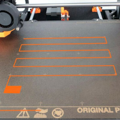
The First Layer Calibration is used to calibrate the distance…
placid grail
but it seems even if I follow instructions (tried 4 heights so far) i still ends up with a stringy bottom
Also it seems there is a slicer software out for for 195 us$ that claims to have the solution to all my problems 🤣
so not sure how to take their advice
vivid helm
placid grail
so not sure how to take their advice
That's Simplify3d. They were relevant in 2012... not so much anymore. Slic3r/PrusaSlicer and Cura are both excellent.
placid grail
should I update my cura ? seems elegoo make their own version and hasnt updated it since 2021. Meanwhile the current version is 5.3 and I have 4.8
maybe that is what is causing my problems
vivid helm
Yeah use the official Cura release, don't bother with vendor builds.
balmy pulsar
as long as the bed is level. just keep lowering the head hom eposition until it sticks basically. keep in mind that the first few inches sometimes never stick due to being cold.
thats why you do a brim. kinda acts like a purge.
placid grail
im just going to try two last things: 1- uses a raft 2- without a raft just auto-calibrate with no z-axis adjustments and see if it shows too high on the visual guide
anyway the part uses less than 1g of PLA
balmy pulsar
before raft try brim
keen raft
placid grail
but it seems even if I follow instructions (tried 4 heights so far) i still ends...
As I said earlier, your printer very likely has an option to adjust Z offset while printing. You should use that. Picking a new height and doing a print will get you somewhere eventually, of course, but it will take ages (takes me 10 or more adjustments easily each time).
But in any case, first layer height is definitely not a slicer issue because the slicer expects your printer to know where it is and until you calibrate it properly, it just doesn't.
placid grail
well
in the prepare menu there is a /x/y/z +/- 8 buttons thing
but im not sure what it does. move the head before the build but it might just go back?
keen raft
placid grail
im just going to try two last things: 1- uses a raft 2- without a raft just aut...
Your printer has an inductive probe, I believe. It's unable to calibrate the Z offset with that.
keen raft
placid grail
in the prepare menu there is a /x/y/z +/- 8 buttons thing
You have to start a print, then while it's printing go into the options (upper right corner on the display). Pick a step size (don't overdo it!), adjust it down and visually inspect the result. Once you see ridges appear, go back up a little.
Not sure if or how the adjustment is saved, though. Might affect only the current print.
placid grail
ok seeing it, part is too little and hidden by the nozzle but Ill keep doing print and adjust it down till it works fine
keen raft
That's why i recommended the large first layer calibration print. It's large enough to see some results 😉
balmy pulsar
the printer usb stick should have a calibration model. it should cover most of the bed
as mentioned, you tweak the bed while its running til its perfect
placid grail
keen raft
That's why i recommended the large first layer calibration print. It's large eno...
I will when it want to behave and the nozzle doesnt pick up the pieces etc
otherwise it seems Ill just waste PLA I doubt the plate will print correctly at all currently
just like the boat thing was supposed to be safe but ended up in a PLA string ball
I mean, brim dont stick. WHat am I supposed to do make a 10g raft each time ?!
keen raft
The test print is supposed to start out not looking good. That's the whole point of it. Once you've set your offset, you cancel it and throw it in the bin.
placid grail
no its not that for the last 5-6 the part sticks to the nozzle
and the part isnt even anymore on the bed but stuck to the nozzle
keen raft
Make sure the nozzle is clean. Move the gantry up to the top, heat the nozzle to 180 °C and use a folded paper towel to wipe off anything stuck to the side. Be careful not to burn yourself.
placid grail
didnt have that problem before, about to hire someone to deal with this stuff...
starting to wonder if I can return it
Like they says about poker Im tilted/angry about this and having to clean that duke of edinburgh so soon after getting it 😠
balmy pulsar
if the part sticks to the nizzle or detaches from the bed, it is either too high, or the bed is greasy, not the right temp, etc.
placid grail
I have calibrated it like 40 times with every possible values between -0.9 and -2.0 it just doesnt work...
Wasn't expecting to waste all my weekend and my life setting this up...
balmy pulsar
pics of bed? video of print?
 shy kelp
Does exist something cheap that permits to auto correct values such as height, extrusion rate and whatever in base of how the filament is extruded out?
Like an auto self calibrating thing
balmy pulsar
at -2.0 does the nozzle hit the build plate directly?
if not, its still way too high
placid grail
at -2.0 if I put a piece of paper I cant remove it without lot of force
with the 2mm high raft the bottom after the first layer is still stringed
but at least the part stuck to the bed I had to use a scraper
Isnt the first layer the raft/brim/skirt thing ?
placid grail
default settings, 205oC filament 60oC bed. Using a 220oC filament 90oC bed is what caused the sticking to the nozzle apparently (it started then). The temp range for the filament is 200-225oC
keen raft
placid grail
at -2.0 if I put a piece of paper I cant remove it without lot of force
That may be too low then.
keen raft
placid grail
but at least the part stuck to the bed I had to use a scraper
You shouldn't have to do that. PEI sheets are supposed to stick while warm and let go when they cool down.
keen raft
placid grail
Isnt the first layer the raft/brim/skirt thing ?
The first layer is the layer that is placed directly on your bed, it can be a raft, but it can also be the bottom of your model
balmy pulsar
205 is low ish. go to 220. but also, just casue it claims its at 205, doesnt mean it is
placid grail
let me take a picture in 3 mins with the 5 last tries
keen raft
placid grail
default settings, 205oC filament 60oC bed. Using a 220oC filament 90oC bed is wh...
90 °C sounds very hot for PLA.
balmy pulsar
too hot yeah
but i think his nozzle temp is wrong here
reading wrong. defective sensor, or something else
placid grail
yeah the 90oC was the nuclear option. When it stuck it melt the bottom and the bottom looking nicer
also even if I 90oC on the printer it doesnt work has to be set in the slicer
ie: the gcode file override my temp setting
balmy pulsar
have you tried the default program that came with the machine?
it should have come with a file or 2
you need to use one of those. to rule out your own files being bad
you could have all sorts of things wrong in your slicer. you need to try the default file first
balmy pulsar
so the printer is fine.....
STOP MESSING WITH IT!!!!!
you clearly have your slicer settings all messed up
placid grail
there was still strings at the bottom on the first one and the first layer burned
ok pics taken

first one just looks ok because it was with the white PLA test roll
but from close it looks like close strings like with needlework
 thin breach
Like *fish says, that test print Buddha looks fine. Get rid of whatever you did to the slicer and go step by step trying to keep it ok.
thin breach
Yeah. So printer is ok
Can you read what temps it is using on your printer screen
Then Use those in the slicer
Resetting everything to the defaults and starting new in the slicer
Do you have an auto bed leveler? Your slicer might not have that active
placid grail
"The Neptune 3 Pro comes with auto bed leveling with an inductive probe. Simply select Level on the main menu and the printer will heat up t" I did that between each print
at the end of it I can change the z-level offset manually then when I click back it saves all of it. It auto-calibrate checking 36 points
balmy pulsar
this has nothign to do with levelling. printer is fine.
placid grail
cant see the buddha printing settings in cura says that gcode file cannot be modifier and printer settings cant be viewed. For the temps it prints at 60/205
balmy pulsar
if layer 1 sticks, layer 2 doesnt, then the problem is the program itself
start fresh
placid grail
yeah that my VI version of the nut...
keen raft
I still think you should do a first layer calibration print and take a video of it, because even the buddha, which is obviously the best print in the picture, doesn't look right to me. There are holes in the bottom and you can clearly see gaps between the extrusions.

It's low enough to stick, but not low enough to be good.
placid grail
ok. I just slice the calibration print with the default settings ?
even on the model there is a grated textures but it looks like the seam / zipper on the outer "cloth"
since it is symmetrical
keen raft
I also don't see good adhesion on any of the black prints. Would also be interesting to see those being printed, to understand what's going on exactly. This one looks like it's very flat on the bottom (maybe this kind of flowed onto the bed because of the 90°C), but the path of the extrusion looks too irregular. You can see the second layer being much more regular than the first.
 placid grail
wait you want me to take a 50 mins video ?!
What do you want me to film exactly ? the end results right ?
is my nuzzle supposed to be one credit card away from the bed, half that, quarter that ?
keen raft
The very first layer is the interesting part. Once you have a good first layer, the other layers should at least print... somehow.
placid grail
the "wait till there is a small pressure on an a4 paper" method doesnt seems to work well (that was the very first print, the buddha)
keen raft
placid grail
the "wait till there is a small pressure on an a4 paper" method doesnt seems to ...
The buddha is the best one of these!
placid grail
yeah but the second print with the same setting flew off
straight H-beam ended up curved
with skirts all around on top
TL;DR: I have two big problems so far, adhesion, messy bottom 3rd show up when I raise the temp: stick to nozzle
keen raft
In my opinion, these are all symptoms of the same issue
faint sky
Here's an example of a dimensional accuracy test print i did. #help-with-3dprinting message
the bottom is supposed to be nice and smooth.

that's what an excellent first layer should look like
if you're not getting results that at least somewhat look flat then something is wrong.
unless you're attempting a raft first but i'll say it again. rafts and brims are a band-aid for things that are slightly off. you have to find the real culprit and calibrate better.
Here's another bottom layer example. flat.

that is a concentric pattern
faint sky
little imperfections at the bottom can magnify at the top,
leaning tower of piza first layer looks good... not so good at the top kind of thing.
i have a saying and i'll continue to say it
"you must calibrate before you can generate"
placid grail
1GB video though
faint sky
cura's calibration shapes plugin is practically mandatory and there are many different things to calibrate. having a brand new printer is done in baby steps, incrementally working your way to bigger and bigger objects.
placid grail
so what do I do with the video so you guys can see it ?
faint sky
youtube? discord has a 15mb limit.
faint sky
probably, i use youtube if i'm going to share a video that's longer than 1 minute
placid grail
wont you see less details though ? I zoomed in at a few points and showed the printer setting and that will be lost
should be uploaded in 4-5 minutes: https://youtu.be/YbcUjaGJfiY
faint sky
it will process the sd footage first, takes time to process 720p and/or 1080p. can take up to 15 mins. just be patient and it'll transcode the higher resolutions if you recorded it in a higher resolution.
360p and 420p will be available to watch immediately, takes time to process the higher resolutions.
placid grail
end result

I can try to retake a pic directly above it it case it warp things as go go up the picture
keen raft
placid grail
end result
So it prints, that's good. But you can see the build plate through it, so it's a lot too high, as suspected.
placid grail
default settngs used, 15% fill
 keen raft
If you print the same thing again and adjust the Z offset in 0.05mm steps, you should gradually see it become a connected surface
placid grail
at 0.2mm that's why it might looks semi-transparent
keen raft
placid grail
default settngs used, 15% fill
It's only a single layer, it doesn't have infill
keen raft
placid grail
at 0.2mm that's why it might looks semi-transparent
It looks transparent because there are holes in it 😉
placid grail
it was at -2.55mm (the value itself is relative to the auto-bed calibration and doesnt mean much) now retrying at -2.60mm
-2.6mm is really close though like it does a good amount of friction on a canadian banking statement sheet
so erm could it be that solidworks isnt converting from .step to .stl correctly ?
should I use something else to convert from step to stl (my printer / cura doesnt accept .step )?
hope i works because I cant go at -2.65mm or the piece of paper wont come off
keen raft
Here, I took a video for you as well: https://www.youtube.com/watch?v=LjV7VV79IWo
This is basically what you should be seeing when adjusting your offset.
At around 0:10 I'm starting to increase my Z offset from the (mostly) correct value to +1.0mm (relative to what it was before, so 1 mm too high). Results are obvious (sticks less, gaps, etc.). At 1:08 you can see the whole printhead drop a mm, that's me resetting it. Then I reduce it down to -0.15mm, you can see some roughness appear on the surface and the whole extrusions becoming so thin they are actually transparent. Then at about 2:20 I'm resetting it again and at 3:23 I'm cancelling the print. Looking at it from above, the last part doesn't actually look that good, but it's still workable. You can see that the irregularities have a certain pattern to them, this may be the bed being uneven.
 keen raft
placid grail
it was at -2.55mm (the value itself is relative to the auto-bed calibration and ...
keen raft
placid grail
it was at -2.55mm (the value itself is relative to the auto-bed calibration and ...
If that was your value when you did the last test print, then start with that and adjust from there. If you still have some of that white filament, using that would make the results more visible.
placid grail
value on test print/youtube video was -2.55m . Now it's printing at -2.60mm. Next I cant go to -2.65mm because the nozzle seems to be colliding with the bed since I cant remove the paper
but -2.63mm might be doable (?)
well I see a difference I think
from the sides i cant even tell it has a bed under it
only from the top with the leds lighting on from the printer

from the side

should I go with -2.65mm now ?
My untrained eye dont see a difference with -2.55mm (first print/video)
keen raft
The difference is very small, if there is any. But it's still too high.
But before you continue, you should make sure that you have really sliced it with the default settings and the correct parameters for your printer.
faint sky
black one looks pretty good. fairly acceptable. still some fine tuning but getting there.
placid grail
keen raft
But before you continue, you should make sure that you have really sliced it wit...
not sure what you mean by that I picked up the default setting auto-configured by ultimaker cura 5.3.1 and in printer it says elegoo neptune 3 pro
can I try to raise my temp to 220oC for the PLA instead of 205oC ?
keen raft
Well if it came with the printer then let's just assume it has the correct settings. There seem to be lots of perimeters (the lines around it), but maybe that's how the Cura people do it. I don't use it myself.
faint sky
yes a slightly higher heat can help it stick to the bed better but there is a perfect setting you can test for by doing a temp tower
well for the initial layer a temp tower won't do nvm. you're still trying to figure out initial layer settings nvm.
placid grail
keen raft
Well if it came with the printer then let's just assume it has the correct setti...
no it didnt. I upgraded it as per the recommendation here. The one that came with the printer was elegoo cura 4.8.0 from may 2021 I upgraded it to ultimaker 5.3.1 about an hour ago from april 2023. In both cases I had to manually add my printer from the list. Then I sliced the plate with the default settings
faint sky
i usually do about 210 but we have different printers. no printer settings will be identical which is why it's important for you to figure out what works best for you.
learning how to interpret results takes time.
placid grail
well Ill try -2.65 and 215 and if it sticks to the nozzle it sticks 😦
I had to scrap off both of the print so far btw so it adheres very well
faint sky
exactly, try different settings but only change 1 variable at a time while testing, use the scientific method, be methodical about your tests.
i usually wait about 15 minutes to let the surface fully cool down. i turn the printer off. then remove the part when the surface is cool. it'll slide right off if you're using a PEI metal sheet.
i can print something massive and when the surface is cool can literally use 1 finger to push the entire thing right off the bed. that's the real advantage to a pei metal sheet.
placid grail
ok test #3: no z-axis change, temp changhed from 205oC to 220oC for filament
keen raft
Just making sure. Most settings aren't relevant until you actually get at least a semi-good print result. But you could theoretically make settings that result in underextrusion (too little filament being pushed through), which would also cause gaps between lines.
faint sky
that's a good point, flow test, estep calibration could help with that.
lots of calibrating to do before you actually print anything substantial
placid grail
it is supposedly a pei bed plate sheet, magnetic
normally print comes off with finger, sometimes have to remove the sheet and fold it a bit. Just too lazy to put it back so I scrape the print off 🤣
faint sky
yes it looks just like the one i have. let it fully cool down below 20C and everything on it will literaly slide right off.
avoid touching the sheet with your hand, hand oils can absolutely affect adhesion.
clean with soap and water
faint sky
let it fully dry, and then on only use a paper towel to push things off the surface.
keen raft
I'd adjust the Z offset until there's a good first layer with no gaps. Everything else doesn't really matter until then. It's possible that you'll come back to a setting that you have previously worked on, but that's just how it is. Everything affects everything, so it's a constant back and forth until you're happy with the result. But the first layer must stick.
faint sky
since i never touch my surface i only have to clean about once a month if i'm printing constantly with back to back 24 hour to 48 hour prints.
placid grail
keen raft
I'd adjust the Z offset until there's a good first layer with no gaps. Everythin...
cant I break the nozzle/nozzle head lowering it too much into the bed ?
faint sky
also the first couple of prints after using soap and water even after drying can cause adhesion issues.
keen raft
I know how you feel! Z offset to this day is my personal demon, because it magically keeps changing on my printer 😛 (Probably thermal expansion or something like that, who knows.)
placid grail
also can printing with the leds on mess things up ?
since it probably uses a laser ?
keen raft
placid grail
cant I break the nozzle/nozzle head lowering it too much into the bed ?
Yes! But you'll damage the bed first.
faint sky
but after you warm up the surface a couple times it'll stick with such force that you would have to put 100lbs of torque to remove anything from the metal pei sheet... and yet if you let it cool below 20C it'll just slide right off. it's magic and amazing.
placid grail
I think it will break things if I go to -2.65mm the lowest I can go is -2.60mm I think. What do you guys think?
keen raft
placid grail
cant I break the nozzle/nozzle head lowering it too much into the bed ?
If you go too low, you will also squeeze the filament into the PEI structure, which might be permanent.
placid grail
ok 😦
faint sky
yeah do not score the bed with the nozzle that would be really bad, getting too close can definitely cause permanent damage to the pei coating.
placid grail
I guess I cant go any lower then
Like it takes me force to remove the paper at -2.65mm
where as currently the force is about mid(like when you have your cell phone on a piece of paper and you try to remove the paper). Where as -2.65mm is like having an heavy box on the paper
faint sky
paper should be a gentle grab, should still move freely but with a little friction.
placid grail
yeah but apparently that doesnt print properly
faint sky
if it's too snug and the paper won't move that's when damage to the surface can occur.
keen raft
placid grail
I think it will break things if I go to -2.65mm the lowest I can go is -2.60mm I...
That's why I recommend doing it during the print, so you can start at a distance that is known to be safe (the one from the paper test), take small steps and watch the result. If you make a large adjustment in advance and it's too low, you'll only know about it after the nozzle has hit the bed.
faint sky
i do that sometimes. adjust the z-offset while it's printing the brim or skirt.
you shouldn't have to but sometimes it is necessary to adjust on the fly.
as long as the bed is perfectly perpendicular to the x-axis gantry and nozzle anyway.
you want all 4 corners and center to have the same friction on the paper, that's basically a good tram.
then you can adjust z-offset finer on the fly if needed.
i actually do it electronically now with my bedibrator but knowing how to do it with paper is honestly one of the first and most important things to learn in the beginning.
placid grail
yeah I think mine needs to be very very close
I cant go any closer now so if it still not enough...à
faint sky
if the nozzle/z-offset is too close it will build up back pressure in the nozzle and will result in a clog.
like putting your finger on a garden hose
so be careful not to be too over zealous with your z-offset there are potential consequences if you're too close.
placid grail
shrug I shined a light on it while it's printing and I cant even see a gap but it still seems to print fine. Maybe my paper too thick
like we dont have A4 here and the procedure says to use A4
faint sky
ohhh
placid grail
so I used an insurance paper sheet 8.5x11
faint sky
if it's a normal sheet of paper most of their thicknesses are the same
can always use a caliper to measure the thickness of the paper?
placid grail
I dont have one also caliper are expensive
faint sky
or feeler gauge for actual precision
keen raft
Paper usually is about 0.1mm thick. Something like a bank statement from the machine might be thinner, I suppose.
faint sky
then use your best judgement, you'll get a feel for what works and what doesn't with experience
all 3d printers kind of have their own personalities, just a matter of getting aquainted with yours.
keen raft
Guess mine is a schizophrenic then! 😛
faint sky
lol oh they can have a mind of their own sometimes
cura updates can mess with things sometimes too
after the last cura update my printer started behaving completely different and i had to recalibrate everything all over again.
 faint sky
multiple pictures help, remember this is a 3D issue so pictures that let us look at a 3d perspective of your print is most helpful not just top down.
keen raft
Getting better!
placid grail
cant do better since I have nothing left I can adjust
220oC is max filament temp and -1.7mm is the most I can go
 misty gyro
In the US, and with an Ender 3 V2, I use "standard" 8.5 by 11, what my wife calls "20 bond" paper. It's the same stuff that you feed to your printer. When leveling the bed, I tighten it till there's just a little bit of resistance to moving the paper.
The one thing I have found is that I must clean the nozzle first, by heating it up and just manually pushing some filament through. It collects in a mess, but you let it cool down again and then break it off to get a clean break, with no left over filament hanging out the nozzle.
keen raft
Well you could check if the extruder really is extruding the correct amount of filament. If it moves too little, that would cause underextrusion, which would make the correct Z offset seem too high.
placid grail
and it does keep the z-axis adjusting
faint sky
oh you can do 230C if you want. those are just recommended specs. i'm not saying you should just that you can if you want.
a PID tune is helpful in figuring out if your nozzle is keeping the correct temperature. 😉
so your printer might be trying 220C but you're actually doing 210C kind of thing.
PID tuning ensure the reported temp is the correct temp.
placid grail
it says the extruder is at 150mm speed. Let me get a screernshot after the print (default setting)
faint sky
yes venture is correct which is called estep calibration, there are tons of videos on youtube that will show you how to PID tune and calibrate esteps.
printing too fast can also cause inaccuries. i generally print at 60mms for PLA for accuracy. the faster you go the more inaccuracies tend to happen.
for PETG I print at 30mms
that is very conservative but i prefer accuracy over speed any day.
placid grail
I dont understand why my printer uses the .gcode settings for temperature filament speed etc instead of the one on the printer...
keen raft
placid grail
I dont understand why my printer uses the .gcode settings for temperature filame...
Because temperatures depend on which filament you use and that's something the printer doesn't know
You set that in your slicer
faint sky
because each line, each layer has a temp and speed associated with it. you can change it on the printer for 1 layer maybe. it's easier just to reslice the model with the new temp and speed settings you want.
placid grail
 faint sky
if something doesn't work i go back to the computer, change the parameters in the slicer, reslice the model, put that gcode on the sdcard, and reprint with the new sliced gcode file.
 faint sky
better!
keen raft
placid grail
it says the extruder is at 150mm speed. Let me get a screernshot after the print...
It's not necessarily about how fast it's going, it's about how accurate it is. If I tell you to walk ten steps, I might expect you to go about 5 metres, but if you're really tiny and have short legs, your ten steps might only take you 8m. Or if you're really tall, you might take ten steps and walk 12m.
faint sky
getting there a little at a time, you're making progress.
faint sky
keen raft
It's not necessarily about how fast it's going, it's about how accurate it is. I...
this, estep calibration is important too.
keen raft
Stepper motors also take steps (hence the name) and the software needs to know how far one steps takes the filament, in this case.
placid grail
adhesion no longer a problem either had to hammer it off the bed 🤣
faint sky
as i said, wait for it to cool down. if you rip it off you could rip off the pei coating and damage the bed
placid grail
fits in the H-beam as wekk without stringing off
keen raft
Very good 🙂 The hammering should stop once it's cold. You can take it off the printer to make it cool faster, the metal plate underneath has quite a bit of thermal capacity.
faint sky
be patient, impatience is the #1 reason i see people people uncessarily destroying their beds by not waiting for it to fully cool before removing parts.
placid grail
I was slightly exagerrating had to slide it off with some force and some hits
can I use my table fan to make it cool faster ?
faint sky
wait until the bed temp is less than 20C to remove parts
placid grail
I usually dont print with fans on
faint sky
yes but turning it off is the fastest way i've found
otherwise it'll slowly ramp down the heat
misty gyro
placid grail
adhesion no longer a problem either had to hammer it off the bed 🤣
The trick I use if it's really well stuck is wait for the bed to cool a bit, and then put it in the freezer. The different co-efficients of expansion usually loosen it enough that it pops right off in half an hour or so.
faint sky
the time it takes to cool down is about the time it takes to go into Cura and change some settings so it kinda works out.
placid grail
I could just take the sheet off and push it off as well I guess
shall I retry to print a beam with the supports now with just a skirt ?
to see if it still strings under bridges
faint sky
i've never needed to put my pei metal sheet in the freezer. just patience and time, let it cool down to room temp and the part will slide right off.
which in the event of a power outage is horrible as your print will never readhere.. there's a good and bad side to owning a metal pei sheet.
keen raft
placid grail
shall I retry to print a beam with the supports now with just a skirt ?
You could try that, but don't forget to continue your setup later. You can still get even better results if you put in the time 🙂
placid grail
Not sure what else I could do besides learn cura to understand the settings
faint sky
oh it's going to take a while before you get everything tuned in just right. manufacturers love to claim it's ready to print out of the box but that's never really true.
placid grail
and adjust the filament speed in the slicer
try to print grid/triangles/wire/etc to see if it does a difference on the same part
placid grail
faint sky
oh it's going to take a while before you get everything tuned in just right. man...
that reminds me of those hobby grade r/c trucks/cars. That's why I dont want one without a local shop to help...
faint sky
something with grid infill would be a good test for that sure. i still think you should be concentrating on initial layer improvements.
placid grail
the mechanics is never correct out of the box
faint sky
but if you want to print something and tired of calibrating for a while go for it. just go with something small to start with in case it turns into spaghetti and never leave your printer alone for more than like 10-15 minutes at a time.
placid grail
faint sky
something with grid infill would be a good test for that sure. i still think yo...
Not sure how I can improve the layer. I dont have an esteps settings and not sure by what you mean with temp tower or how to measure nuzzle temp (all I have is an IR handheld thermometer I dont have a calibration things like my hakko iron would need). Also III you mentionned filament speed but that is in the slicer
After that Id need to change the firmware (klipper) and/or play with gcodes
keen raft
placid grail
After that Id need to change the firmware (klipper) and/or play with gcodes
Don't try to use Klipper until you know exactly what you're doing. Klipper is quite complicated, compared to the usual default Marlins on new printers and at the same time allows you to break everything at will. Quite literally, actually.
placid grail
mind if I take a break ? Going to reprint the boat thing in the meantime to see if the piece will still fly off / turn into a string ball
placid grail
so day 3 of the Battle of Elegoo
Im printign the tool holder that came with the sd card. My z-axis setting didnt save when the printer was powered off so I had to manually adjust it before printing. Filament says it comes out at 150 mm per minute but all I have to adjust print speed is a % thing
keen raft
placid grail
so day 3 of the Battle of Elegoo
Sounds like something Napoleon might be involved in 😉
placid grail
I still had to scrape the previous part skirt after cooling off overnight with 3d printer turned off
placid grail
keen raft
Sounds like something Napoleon might be involved in 😉
yeah that was the joke 😄
make it sounds like it's a huge battle in a military campaign but with my 3d printer 🤣
as in once the one battle is won the war itself isn't over and will last for the lifetime of my 3d printer 🤣
keen raft
placid grail
Im printign the tool holder that came with the sd card. My z-axis setting didnt ...
Not sure how saving this works on your printer. If there's no way to permanently save it during a print, then just take note of the adjustment you make and add/subtract that from the offset that you can change and save in the settings menu after the print is done
placid grail
1st layer looks fine skirt is bad because the z axis resetted to -1.5 instead of -1.7 before i found out so I changed it somewhere between the skirt and the part

business end ff the part
 keen raft
placid grail
I still had to scrape the previous part skirt after cooling off overnight with 3...
keen raft
placid grail
I still had to scrape the previous part skirt after cooling off overnight with 3...
I had some issues as well with getting single layer prints off my PEI sheet. I ended up making my skirts higher. There's a setting for that in the slicer.
placid grail
cant slice that one it's to make a tool holder for the tools that came with the printer
and fix it on the nozzle steel vertical bars
couldnt wait before I dont want to lose my tools somewhere and have difficulty finding them and so I need it to clean my apartment
it's going to take like 3h to print
can 3d printers make nice formed letters to labels things ?

Like I have these separators for my tackle fishing box that I uses for electronics
Would be great if I could print my own except with letters to see what's in there without having to google the sensor chip number/model
keen raft
You can do things like this, both embossed and debossed, but it's not particularly easy to read and the minimum text size is a lot larger than what would be achievable on paper. You could print embossings in a different colour to improve that, either with a dual extruder or by pausing and changing filaments. You could also get creative and put stamp colour on an embossing or something like that.

Personally - I've found all of these to be too much effort, so I'm just writing labels. Didn't even bother to print them. Saves time, is readable enough and having a removable label lets me re-use the compartments for other things without having to re-do anything fancy.

The compartments themselves on the other hand I did print, because that allows me to re-arrange things inside my boxes very easily
placid grail
I have lots of label yeah and a dymo label maker
going to write the price on em as well
now that my printer works much better ideas for custom holder keeps poppin in as well as with the wall velcros stickers I have 😦
going to have to speedrun learning solidworks
Also I have a gap between my big L desk and the counter. Currently it's empty boxes that close the gap
but could fill in the various holes between the boxes and change of elevation with a carbon vinyl and a couple of custom holders/drawers
keen raft
You'll be buying a second printer soon if you have such a long list 😉
placid grail
nah if I had something big Id use the makerbot at my makerspace
but I figure hanging 200mm would make it looks better
I can wait during the weekend lots of rainy day still in my state
ie
 faint sky
until you get it printing more accurate i wouldn't try labels. they won't do tiny text very well. large fonts they might and things like house numbers can definitely do very large. better to use label makers for legible small text.
again, accuracy plays a big part in how fine of numbers/text you can print. you can emboss it or raise it to paint the lettering.
placid grail
Didnt seem to get a reply to this: "Not sure how I can improve the layer. I dont have an esteps settings and not sure by what you mean with temp tower or how to measure nuzzle temp (all I have is an IR handheld thermometer I dont have a calibration things like my hakko iron would need). Also III you mentionned filament speed but that is in the slicer"
What else is there to improve at the moment ?
keen raft
placid grail
What else is there to improve at the moment ?
You should calibrate your E steps. That means making sure that when the slicer wants to move X amount of filament, that's actually what is transported. This ties into your first layer calibration because it might be underextruding (transporting less than what is expected by the slicer), which would result, for example, in first layers with holes even at the correct height.
After that, check your Z offset again. I'm still seeing a few holes there and unless you have to do any major changes to the E steps, that's a height issue.
placid grail
I cant go lower on the z offset
I zoomed with my camera and as far as I can tell it is touching the bed
it is probably not but my eye cant see that small
event at 8x zoom there dont seem to be a gap
keen raft
placid grail
event at 8x zoom there dont seem to be a gap
These look like holes to me. Might be reflections, though! You'll probably be able to see that better when looking at it.
 placid grail
keen raft
These look like holes to me. Might be reflections, though! You'll probably be ab...
placid grail
keen raft
These look like holes to me. Might be reflections, though! You'll probably be ab...
no I mean a gap between the nuzzle at -1.70mm and the bed
when the nozzle is lowered and printing hasnt started yet
Im saying i cant go lower because there is no gap and I might damage the bed if I go any lower
I checked with my 8x lens headband
keen raft
Not sure why that might be. Maybe the mesh isn't loaded then?
placid grail
also for e-esteps Im seeing this for my printer (google): https://www.reddit.com/r/ElegooNeptune3/comments/yesqvj/esteps/ which redirects to https://www.reddit.com/r/elegooneptune2/comments/rbhcrt/guide_e_step_calibration_for_elegoo_neptune_2/

reddit
39 votes and 26 comments so far on Reddit
but it talks about replacing the firmware / sending gcodes (?)
so Im not sure it's the right thing and the video in the thread is gone
placid grail
keen raft
Not sure why that might be. Maybe the mesh isn't loaded then?
oh that is probably because it started to print at -1.50mm (too high)
until I saw in the settings a minute later that turning off the printer had changed it back to -1.5mm
and put it back to -1.7mm
keen raft
placid grail
oh that is probably because it started to print at -1.50mm (too high)
That's possible! It usually starts with the outline and that's what looks the worst, over on the left!
placid grail
yeah that is what I was saying it messed up the skirt and the zone inside-out of the skirt like the holes on the bottom
Ill know for next time but doesnt seem worth it to trash the whole thing when I will rarely see the bottom of it
and the tolerance is high because it's for tools like allen keys, screwdriver, keys to adjust the big bolts under the belts etc
so I dont think it alters the functionality too much

top-right is a skirt (sorry bad camera angle / camera handling make it looks like a blob/deformation)
so is e-steps really this: "Set up octoprint Install eeprom editor plug in Set a spot on filament to measure from Extrude 100mm Measure Google esteps calculator Follow the prompts Place new value into e steps in eeprom editor Save Profit" ?
Or I need to find a more newbie guide ?
keen raft
How you extrude doesn't really matter. Since you can move axes from your printer display, maybe you can also extrude from there?
 keen raft
If you try to extrude 100mm from there and exactly 100mm come out, you're done and don't have to change anything.
faint sky
ricky impey is my go to guy for learning anything about 3d printing. it's a different printer but the general concepts are the same for practically any bed slinger. could learn a lot just by watching a lot of his videos. https://www.youtube.com/watch?v=qOj8L0IXcfA
In this video i'm going to show you how to calibrate the E-steps on your Ender 3 v2 3d printer. This is a very simple quick process that you can do completely on the printer and should take no more than 10 minutes from start to finish.
Why do you need to calibrate your e steps?
In basic terms, calibrating your e steps ensures that the right am...
the concept of e-step calibration is so simple you can do it with a ruler.
e-steps can make a difference in overextrusion or underextrusion situations without having anything to do with settings. it's part of physical calibration of your extruder gears.
placid grail
I guess I should have taken classes before (3h free class at my makerspace) but madbodger/hem convinced me recently so I didnt foresee this 😦
faint sky
which should be correct from the factory but even being 1mm over will cause extrusion issues more obvious the higher you go. it can mean the difference between making spaghetti or nozzle grinding into your part at higher heights. everything might be fine with small parts but when you go big like a 6" tall part even being 1mm off will make a huge difference at 6 or 10" tall parts.
there are hundreds of parameters. it's like working on a car. it does take work to calibrate and tune in. when you get it working right it'll be worth all the effort when you start making amazingly accurate prints that can snap fit together.
placid grail
print half-done about 1h30 left
faint sky
the latest tool holder print is looking pretty good so far. the infill grid lines are stacking great!
placid grail
I dont have a vehicle or driving license and that's exactly why. Also the public transportation is very good so hard to justify if you dont go out the city
Also I just cant accept someone else doing easy stuff for my safety like brake pads
faint sky
yes there will be small imperfections between gaps sometimes that don't get filled, there are slicing parameters that can help fix that but in order to not overwhelm you it's best to start slow and learn all the basics step by step.
placid grail
well from what I understand you guys are telling me the print quality is OK but it could be much better
So I gotta keep improving it little by little and not commit to big projects until that is done
like buying my 4 other PLA rolls and 1 petg so I can use more than one color or my desk gap thing
faint sky
yes, it's at what i would consider the lowest end of acceptable right now which is still far better than it was a couple days ago. you're making good progress.
when you get it all dialed in the quality you'll get out of it will be easily 4x better than what you've got now. you have to learn how to get there, learn about all the things that make your printer work the way it does, make mistakes, learn from the mistakes, that way if you encounter them again in the future you'll know how to fix it yourself and won't need help. 😉
gotta learn to crawl before you can run. and there's a lot of learning left to do. you're making good progress, right on track. it takes time, patience, and learning. you're doing it right. 👍
placid grail
That is why I got a 3d printer and want to print asap so I can start making construction. Seller of this was nice enough to share step/stl since they sell a metal version and they arent interested in selling a less durable/resistant plastic version

I really like the modularity of it. H-beam, slide fastener in. Screws it with M3 machine screws etc
in my tests with the H-beam a couple of days I tried to destroy it including with an hammer and PLA seems to works very well for it
I know I wont be able to make 2 meter long construction like with that kit. But a cubic feet seems doable
faint sky
you're almost there but still probably don't have the accuracy with holes to pull off a part like that. holes are kind of a different animal. holes have their own settings too in some cases.
placid grail
yeah so far it seems Ill have to hammer in the nut in place
and take em out with a flat screwdriver head and hammer, seems impossible to get enough accuracy on every nut
faint sky
filament has thermal expansion and contraction
so what you see in a model might not be the accuracy you print with
placid grail
 faint sky
if the holes are slightly too small that's actually a good thing. you can use heat to insert the nut or bolt.
placid grail
you can see the tests I did with it with a few nuts and M3 in it
deformed because of my tests to break it
faint sky
use a soldering iron on the metal and you can melt it into place. it's a slow process but works the same as a heat insert.
placid grail
I wanted to be sure that when I collide it into the wall at 16mph when I make a vehicle with this that it wont break easily
faint sky
if you need threads in the filament then you can run a tap/die set and create your own threads.
placid grail
Ill probably rework the model in solidworks and remove the threads
just dont know how yet
faint sky
a tap will chew right through filament because they're designed to tap threads in aluminum usually.
placid grail
And make the m3 holes smaller to insert the screws with my soldering iron (the grey screw was inserted with a soldering iron and screw driver)
faint sky
taps work excellent on 3d printed parts
placid grail
Like I had my iron at 650oC and stuck it to the metal part of the screwdriver and screwed the screw in as normal. Seems to work very well
but it's not meant for permanent installation... it's supposed to be a kit
and putting 4 tapped inserts per 80mm beam would costs .40$ each
faint sky
you can just melt a screw with the soldering iron on top of the screw. the filament will melt around the threads. let it cool. then unscrew it and voila tapped threads.
placid grail
oh I thought the PLA threads would snap if I did unscrew it since they would be glue to the screw
faint sky
a tap isn't 100% necessary for screws, just use a soldering iron on the screw itself and melt it into the part. you don't even need a hole. the heat from a soldering iron will make its own hole.
is the screw made of pla or metal?
if the screw is metal just melt it right into the pla
placid grail
very nice print 🙂 🙂 🙂
faint sky
having a hole there does help as the 3d printed part will make circular walls around that area.
placid grail
wish you could see my smile
faint sky
otherwise it'll just be a void most times and infill, so could be a void with nothing for the screw to grab/melt onto.
at least attempting to make a cylinder hole there does help 😉
placid grail
the nice thing with the above is that I can also use stainless steel or titanium brackets with it
faint sky
yup, use any hardware you want.
placid grail
only the m3 nut to slide in the H-beam and the H-beam need to be PLA
Wish I could buy it but it costs x3 the base cost to import in canada...
getting a cheaper version with PLA/petg is going to be much less expensive
faint sky
you can use m3 heat inserts which already have threads but you have to make the cylinder hole for the heat insert to grab into, otherwise you get into the same situation where you might try to melt it into an infill void.
 placid grail
Still have to order longer m3 screws though so I cant really do everything at the moment even if the 3d printer was perfect
I dont really have much hardware atm and canadian tire/etc dont really sell hobby sizes screws
they start at like M8/#10
faint sky
m3 is the same size as pc case screws 😉
placid grail
yeah I know but that is the problem
I have m3 PC screws
they are short for SSD etc
too short for this so I need m3x10 minimum and 3 steps until like m3x80
faint sky

Wanna improve the connection strength between your project's 3D-printed parts, and also have nice clean surfaces? Instead of gluing bits together, or screwing plastic screws directly ...
placid grail
was planning to get lynxmotion M3s off robotshop since adafruit stuff is 100$ min order from digikey to avoid customs / fedex/dhl random charges
but Ill keep the above in mind too and see if they dont have something like that
cause lynxmotion is really premium... they sell 50k$ UGV kits after all
faint sky
you can get them from aliexpress or pimoroni, practically anywhere. heat inserts are easily available as well as m3 screws.
keen raft
Amazon sells all of these things around here, maybe that's worth a try?
faint sky
or amazon to yes
placid grail
I looked but couldnt see a kit on amazon.ca that didnt include bloat like other sizes like m2 to m8
they dont seem to just have a huge kit of machine m3 at verying lenghts with standoffs
faint sky
it's actually very helpful to get the kit with multiple sizes. at first i thought i only needed m3 but a lot of adafruit boards and modules also use m2.
placid grail
At the moment Im planning a digikey 100 pack of each but the inserts are 3$ each and 30mm 😦
that seems doable
 faint sky

AIEX 100pcs 3D Printing Brass Nuts, M3 Threaded Insert Knurled Brass Nuts Female Thread Knurled Heat Embedment Nut for 3D Printing Parts Loptop Automotive Plastic Shell(M3*4.6x5.7mm)
placid grail
why does it says plastic shell though ?
wont that melt / mess it with the pla when I heat it ?
vivid helm
Those inserts were originally designed for injection molded parts.
And yes it does melt it slightly. You usually want to run the soldering iron at the low end of the printing temperature range printed on your filament spool.
For PLA that's usually 180C.
placid grail
My soldering iron is a bit weird not sure whats going on
or the screws doesnt conduct heat as well as I though
like nothing happened until it got to 650oC
Id have to pay 200$ (ie: more than the iron) to get the official hakko calibration thing
like I left it on the screw while it was heating to 650oC...
keen raft
Are you sure that's not °F?
vivid helm
That sounds like °F.
vivid helm
That sounds about right, and way over what you want in most cases.
placid grail
someone Dmed me and said: "your bed leveling or nozzle offset is way off all those lines should be squished a little
which printer model is it. i can see all the lines on the top are separated their not touching thats going to be super brittle do you have any feeler gauges?" about my current print 😦
fin9shed part from the top with 2x zoom

bad or ? (besides the skirt when the nozzle was set up at incorrect height)
keen raft
Certainly doesn't look terrible from the top
It's a bit difficult to tell on pictures whether the surface should be a bit smoother
vivid helm
Is that the bottom or top?
keen raft
The top with zoom
vivid helm
Looks a little like under extrusion or a partial clog to me.
faint sky
looking much better, it didn't turn into spaghetti and sppears to be a functional part
you can enable ironing for the top surface and it'll do a shallow pass on top to smooth the top surface out.
can only use ironing if your ceiling/bottom layers are set at about 4-5
otherwise you could burn through the top layer and it'll create holes
i see that happen a lot with people who have top layer set to 1 or 2
overall that is a good print, if it works for your purposes then it's a success.
when it comes to threads and holes your tolerance setting can make a difference
tolerance test pieces can help

Video sponsored by PCBWay - https://www.pcbway.com - PCB Manufacturing, 3d Printing, CNC parts, and more..
Also get $5 of credit if you sign up to PCBWay using this link https://www.pcbway.com/setinvite.aspx?inviteid=575537
Fed up of 3d printed stuff not fitting together after you print it? Me too. Let's do something about it.
Get the calib...
middle, inclusive, ane exclusive tolerance mode. what it is, what it does, and why it's important.

Print in place parts, screw threads, all these kind of things tend to print with too little tolerance and you end up with an unusable part. Well, ONE of the reasons for this, and also one of the solutions for it, is to change slicing tolerance.
Watch to find out why.
For more information about how cura actually works out its slice geometry...
placid grail
enable ironing ? not seeing that in the slicer?
faint sky
probably in expert settings. if you do a search in settings for ironing it should come up.
if you're using cura as your slicer anyway
keen raft
placid grail
enable ironing ? not seeing that in the slicer?
It's in the Top/Bottom category in advanced mode. But like many settings, this is something for fine tuning an otherwise great print.
You should take it step by step, from the most important to the least important settings. Or from the most apparent to the least apparent issue.
faint sky
it's not really important, will just make the top surface look a little nicer and since it's for a tool rack where you'll see the top finish might be desirable.
placid grail
I was DM opposite things so Im not sure anymore
Also apparently my printer is : "this printer is just an ender 3 with some fancy covers on the slot frame and a direct drive hot end"
 keen raft
placid grail
I was DM opposite things so Im not sure anymore
keen raft
placid grail
I was DM opposite things so Im not sure anymore
People should put their opinions out in the open, in my opinion 😉
placid grail
oh it's not here
I just shared my print on an unrelated discord and someone pounced on it
keen raft
placid grail
Also apparently my printer is : "this printer is just an ender 3 with some fancy...
Look at any shop that sells 3D printers. Why do they all look identical? Because they are all knock offs of the same open source material.
placid grail
they have 4 printers in their lab next to next all ender 3
keen raft
There are very few companies who can honestly claim to provide substantial innovation to this field.
placid grail
seems the opposite of the ham community
faint sky
most 3d printers are just knock off prusa's in one way or another but they're all kind of taking different evolutionary tracks with their software except for the slicers. it's usually cura, prusaslicer, klipper, or slicer3d
placid grail
Like I though Id get an antenna at like best buy. But the best antennas are made by peoples like me in their garages
faint sky
that's best discussed in the hw channel. antenna's have nothing to do with 3d printers... yet. 😛
placid grail
And I was told to avoid creality...
placid grail
faint sky
that's best discussed in the hw channel. antenna's have nothing to do with 3d p...
eh it ws just 1 comment about 3d printing being the complete opposite 😄 so hybrid sentence
it's just a bit surprising that some electronicsw fields are complete opposite of each other
faint sky
umm and you have have an elegoo right which is just a knock off of an ender. weird advice.
faint sky
unless you're going with a bambulabs all bed slingers operate almost identically with exception to core x/y maybe
opinions, everyone's got them
balmy pulsar
peaople ramble on a bout build quality, but the printers have gone from $600-$800 down to $200... what are you expecting?
vivid helm
faint sky
most 3d printers are just knock off prusa's in one way or another but they're al...
Klipper is a software+firmware framework, not a slicer.
vivid helm
faint sky
unless you're going with a bambulabs all bed slingers operate almost identically...
There are a variety of different bed probing approaches, also different z axis drive types and hotends.
 signal yarrow
I've got a 2D plotter I'm trying to send Gcode instructions to. I can send various commands like G0 X10 Y10 just fine. My plotter doesn't have limit switches so I'd like to be able to specify where home is after moving G0 commands to get my plotter head where I want it. I thought G92 X0 Y0 would do the trick but it doesn't.
If I type
G28 ; Home the plotter head
G0 X10 Y10; Move 10 in x and Y
G92 X0 Y0; Set the current position to be home
When I then type G0 X0 Y0, the plotter head moves X-10 Y-10.
What am I doing wrong here?
faint sky
could try M206 to set the home position? You can find out what the home offset is set at with M503
Marlin Firmware
Use M206 to apply a persistent offset to the native home position and coordinate space. This effectively shifts the coordinate space in the negative direction. See examples below.
from there you might be able to use the auto home function G28
Marlin Firmware
When you first start up your machine it has no idea where the toolhead is positioned, so Marlin needs to use a procedure called “homing” to establish a known position. To do this it moves each axis towards one end of its track until it triggers a switch, commonly called an “endstop.” Marlin knows where the endstops are, so once all the endstops ...
for a plotter might be worth looking into the cnc_coordinate_system https://marlinfw.org/docs/gcode/G054-G059.html
though it seems as if you're already gone down that path without luck. likely because you're not setting home and offset correctly.
without liimit switches your workspace dimensions have to be correct and there has to be a way it can verify home is actually home.
vocal flax
@placid grail i am not sure if cura allows but try to calibrate flow than e steps. Generally speaking better to not change e steps. In Prusa slicer flow ratio is purely controlled by slicer, and can be calibrated to per filament basis. Additionally, if you calibrate e steps you will be correcting e steps for certain length but also introduce error for other lengths
 verbal sail
I'm making some card edge sockets and am thinking of doing them in resin. Is there going to be any issues with that?
verbal sail
Yes. Volts up to I believe 400
balmy pulsar
will it get warm?
and will it take and load/stress?
for example a gpu socket would get too hot and put too much strai
n
verbal sail
Not sure. It's for a nixie/geiger project
verbal sail
Radiation detecting with a nixie tube display
balmy pulsar
"real" slots from molex are fibreglass reinforced nylon usually. for reference
ah
you live on dartmoor? haha (only place i know off hand with high ambient radiation)
verbal sail
Madbodger might know if it would get hot
verbal sail
balmy pulsar
you live on dartmoor? haha (only place i know off hand with high ambient radiati...
No. Just like old tech and uranium glass
balmy pulsar
ah nice
verbal sail
This is actually the beginning of a tricorder project as well
balmy pulsar
fun
i guess theres one way to find out... print it and see what happens. haha
resin generally you need to watch for deforming if its too warm, and cracking cause its pretty brittle
verbal sail
I'm wanting to use resin for the dimensional accuracy. I'd add fiber glass or even shredded bakelite if I could but it's a library printer
balmy pulsar
ah. dont hurt the poor library printer.
im not sure that hack even really works
seems more of a big mess
verbal sail
I can't afford a resin printer right now.
verbal sail
balmy pulsar
im not sure that hack even really works
One way to find out 🙂
balmy pulsar
i saw one for $99 recently, they are getting crazy cheap
but anyhow, yeah, try a standard resin print and see what happens
vocal flax
balmy pulsar
"real" slots from molex are fibreglass reinforced nylon usually. for reference
For a good reason
vocal flax
verbal sail
Yes. Volts up to I believe 400
For 400v you need really robust material something that doesn't catch on fire because suppressing the arc will be difficult. Commercially glass fiber nylon is used because nylon is uv resistant and gf gives fire suppressing abilities
verbal sail
vocal flax
For 400v you need really robust material something that doesn't catch on fire be...
I need something though. Recommendations for a low minimum printer?
vocal flax
I think you should just buy the connector
verbal sail
vocal flax
I think you should just buy the connector
Can't. Custom job
vocal flax
Okay then I have no recommendation just informing on potential challenges
verbal sail
Looks like high temp resin may work but I have to find a print service. Doubt my library will have that
keen raft
verbal sail
I'm making some card edge sockets and am thinking of doing them in resin. Is the...
How do you plan on making the electrical connection?
I think that's the real challenge here 😉
 white idol
Hey all! I have had some issues with my Ender 3 Pro (v4.2.2 motherboard). The BLTouch decided to just probe the air. It had been working quite fine until one day when it stopped. IDK if this helps, but I have dual Z axis installed, and the BLTouch stopped working shortly after I installed it. The actual BLTouch works fine - I tested it under the test section of the menu. Any help would be greatly appreciated.
Here's a video:
Anyone know what's happening?
white idol
Nevermind - fixed it!
placid grail
my analog calipers arrived a few minutes ago so I can measure my 3d prints
verbal sail
keen raft
How do you plan on making the electrical connection?
Digikey and mouser sell card edge contacts. For example: https://www.te.com/usa-en/product-583259-4.html
balmy pulsar
neat. i assumed that was the case. What is the reason for a special connector though? molex sells kinda eveyrthing you can imagine already.
verbal sail
custom made boards really
balmy pulsar
ah
placid grail
what do i need to know to figure out the thickness / fill rate / 0.12 or 0.2 layer for a panel mount for something like that??

I dont need the thickness to install it obviously but to prevent it from turning. Also if it would be good to use my iron to melt the plastic around it when I install it so it remelt more closely to it (it is a on/off physical key switch)?
 wind glade
placid grail
what do i need to know to figure out the thickness / fill rate / 0.12 or 0.2 lay...
wind glade
placid grail
what do i need to know to figure out the thickness / fill rate / 0.12 or 0.2 lay...
What's your install application? If you're panel mounting, just use some calipers or a ruler, measure the switch diameter, desired wall thickness, etc, and build your panel and home mount off that.
Also, It looks like one section of that threading is flat. Create your circle in CAD and flatten one side of the circle. Then make your extruded cut off the flattened circle. that should prevent it from turning. If it's a push button, or a flip switch, you may not need to worry about it turning. Get that nut tight enough and you're golden.
finally, I would avoid trying to melt the plastic to make a better fit, for a number of reasons. 1) you'll get metly plastic all over your soldering iron, and it'll smell each time you heat it up. 2) if you modify your part too much, you either have to re-print, or you're out of luck. 3) If the switch fails, you want to be able to replace it. if you force it into a melted hole and let the plastic re-form around the part, it may not be easily removable.


Kinda like this.
measurements are an estimate.
placid grail
wind glade
What's your install application? If you're panel mounting, just use some caliper...
No it's a key switch about 15mm diameter. Metal, metal key. It's going to produce some torque when I turn it to the on position and off. Dont want the box with it mounting off to shear off
I figure with PLA I'll probably need a 80% fill percentage
wind glade
Oh gotcha. How much force does it take to turn the key? If you print with the mounting face parallel with the bed, I think it'll be stronger than if if was vertical. that would let you get away with less infill.
placid grail
the size of the circle need to be what is under the key plate so I can fit from the front and turn the nut under it to affix it until it is fixed securely
hard to say how much force, my body dont have sensors for that but Id says about the same as those big office fillings cabinet with a lock around the same size for all 3 drawers on it. It's not as difficult as a car
But say twisting with human fingers at around medium force
seems to take a bit more for pushing. Id say it's similar to a house door lock when it work the first time without issues
wind glade
placid grail
seems to take a bit more for pushing. Id say it's similar to a house door lock w...
Yeah, the thicker your mounting panel, the less infill you'd need, because that twisting force is shared along the whole depth of the hole. And that kind of switch would def have a keyed edge to prevent it from turning. Same with inserting the key: Shouldn't take too much force, so thicker may be better. And honestly, you can make the mount point thicker on the switch than in other areas, and that will save material as well while still providing rigidity. pretty neat switch!
You may want to bump up the infill in that area, just to be safe, but I think as long as your walls are thick enough (5mm at the extreme min to 15 mm at the extreme max, you'll be fine. that's the beauty of 3d printing: If you get it wrong, try again! Print a smaller section and see how that feels. if it feels weak, you can increase a variable to make it stronger.
and I'd still stay away from doing any melting. I've never had luck with that personally.
faint sky
For something like that you'll want a high amount of infill like 85% otherwise when you go to screw it in it will crush the top/bottom layer with force.
A low infill of 25% for example will crack under the torque required to make a tight fit.
I actually have a video on installing one of them in a PC but it's on a front panel made of thick plastic.
The notch you designed into it will definitely help. I recommend doing some small square test prints instead of the full panel size just to ensure the hole and notch will be the right size without taking into account thermal expansion.
I'd make the part at least 10mm thick, the thicker the better. 20mm would be great but also would take twice as long as 10mm.
placid grail
it is for a joystick like device so 20mm would be fine. Even planned to add a brick slice at the bottom of it or some used metal for weight so it doesnt move on my desk
faint sky
Due to previous chats I'll assume you don't have a deep well automotive socket. A wrench will be required as the lock is too deep for a regular hex socket set.
placid grail
I didnt think of that or even screwing it in honestly
just planned to hammer it in like when you hammer a screw and to have the nut provide most of the force to prevent torque from moving it
faint sky
This might give you some ideas of how to go about it.
Child proof your PC. Modification to replace a PC power button with a lock/key switch.
Momentary Key Switch - $10 Amazon Link: http://a.co/cKWUxQS
Sound Deadening Insulation - $21 NewEgg Link: https://www.newegg.com/Product/Product.aspx?Item=9SIA27C4WD9892
keen raft
faint sky
Due to previous chats I'll assume you don't have a deep well automotive socket. ...
That problem goes away if the hole es deep enough. Like so:

Assuming this is printed front down for aesthetics, it also puts pressure on the layers, which is good, and you can add some sort of rotation-inhibiting washer in between
That's what I'd try, anyway. There's probably ten ways to do this 🙂
faint sky
True. It'll add more material and time to the print and you'll need a wrench to tighten it in the end anyway.
placid grail
what does 0.2 - 0.5 layer height mm mean on a print instruction ?
Im confused that it is a range
Also I cant find wall count = 4 on the ultimaker cura. I googled but it often only thickness (mm) and wall line count (and not wall count)
balmy pulsar
it means that is that reange that would be an acceptable print
but you need to also know what nozzle they expect
0.5 is generally too high for a 0.4mm nozzle
cura has a check box for layer/units
what are you printing that has instuctions like that? rc plane?
placid grail
r/c car the tarmo4
Seems much cheaper than a full r/c (that starts at 350$ just for the shell/chassis at this 1:10 size)
placid grail
atm the moment I just want to print the basic parts without holders for anythingh so I can get a size of where the elecronics like pi etc will go
balmy pulsar
i printed most of a 3dsets land rover
placid grail
so it's ok if the print isnt perfect
balmy pulsar
gotta finishe it before xmas
placid grail
Im ex-MulhorandEmperor btw
balmy pulsar
ahhh, back to ignore...
haha
j/k
😛
i cant find a pic of my land rover
i used a 0.4 nozzle 0.2 layer height
only downside is its sloooooow
placid grail
this one can go at like 40 mph before modding
but I dont really care about that and will probably uses a tailer type motor instead if they fit
just cant tolerate using 2A "toys" motors but this is all DIY electronics offer
whereas r/c stuff starts at near 20A continuous and 60A burst
this will let me finally advance in that and get parts little by little
I thought that 0.2 - 0.5 meant like start with 0.2 then end with 0.5 or something like that
balmy pulsar
the 3ds sets cars take about 2 weeks on a normal printer like a creality or anycubic or prusa
obviously thats not one single print. many. like 100
ha
placid grail
they are using the 1:10 is too big for most printers
so let's print the chassis in 3 parts and screw it together with M4 bolts
balmy pulsar
ah, yup
placid grail
I feel a bit nervous 🤣
balmy pulsar
mine is, um, 20" long fully assembled
placid grail
It will probably be all messed up
wish there was elegoo neptune 3 specific intructions or ultimaker cura instructions
balmy pulsar
its all prety generic. the neptune is no different than any of the others
fatter layer heights make the print fatser. but less detailed.
some parts are fine for that. other like a gear box etc need the finer detail
placid grail
Im mostly concerned about hull strength when it slam into a wall at 40mph 🤣
not that I will actually run it at that speed because of sensors etc
but I might at the start
that's why Im a bit surprised at the range
placid grail
yeah that's another advantage
not breaking the 600$ traxxas chassis and losing all my money for nothing
balmy pulsar


 placid grail
Im confused about something too. say to change the orientation (like print it left to right) but I cant rotate the stl file buttons are grayed out
kinda lost as to what orientation this is / hoiw Im supposed to know
 balmy pulsar

 placid grail
I guess the biggest advantage is that I know more I can reprint the chassis and adjust stuff
also if I need to add additonal holes/mounts for a pi etc
balmy pulsar
placid grail
kinda lost as to what orientation this is / hoiw Im supposed to know
yeah
placid grail
or an universal plate on top of it
balmy pulsar
i silver leafed parts of mine, then paint on top, so it can scratch up and see metal underneath
works well
placid grail
this is how I found this. Was trying to find a step file for an axial scxii deadbolt
to know the universal plate size for a pi etc then I discoverd this. So nvm the commercial r/c 🤣 shrug

 arctic dragon
placid grail
Im confused about something too. say to change the orientation (like print it le...
arctic dragon
placid grail
Im confused about something too. say to change the orientation (like print it le...
Are you trying to rotate the part on the plate, or define the order the slicer prints features?
As long as you have the same face on the plate, it shouldn't make a significant difference.
placid grail
they just say to change the orientation like shown in their screenshot to maximize the material strength
bu5t I dont know an axis key on their screenshot
so I have no idea what rotation it is on
it's probably what these yellow and red lines are for on the model ?
balmy pulsar
press rotate button then rotate manually
arctic dragon
The only axis that makes a structural difference is the vertical one. That should be just fine.
balmy pulsar
OR, you can select the surface you want on the plate
arctic dragon
The lines on your screen are for moving the part on the plate. To rotate, the rotate tool is somewhere on the left of your Cura window.
placid grail
I had to do select all models to rotate it
not sure why it wasnt selected by default
probably even going to get different filament color for different parts
just sucks ill need the flexible filament TPU thing to finish it from a specific brand 😦
arctic dragon
placid grail
says around 4h for the chassis 😦
Sounds like you can consider switching to a larger nozzle, especially if the upper bound of the layer height is 0.5mm. If you get a 0.8 or 1.0mm nozzle, you can print with a 0.5 layer height in a lot less time.
balmy pulsar
eventually you ca progrees to larger cars 😛

 placid grail
nah 1:10 is very big and could crush my head and cause serious injuries 😦
balmy pulsar
placid grail
just sucks ill need the flexible filament TPU thing to finish it from a specific...
for tires? meh. i bought tires for $50. seems smarter.
placid grail
Once got ran over by a 1:10 cralwer my brother used and it even crawled on me
placid grail
balmy pulsar
for tires? meh. i bought tires for $50. seems smarter.
no the drivetrain system/gearbox. It's even bolded in the instructions
arctic dragon
placid grail
just sucks ill need the flexible filament TPU thing to finish it from a specific...
TPU is one of those things where you can substitute for a similar material unless you need a specific shore hardness. True rubber-like TPU is pretty hard to print and even harder to consistently extrude within dimensional tolerances, so there are a lot less suppliers for the softer variants.
balmy pulsar
placid grail
Once got ran over by a 1:10 cralwer my brother used and it even crawled on me
those red wheels are for a full sized pocket bike. Sadly they failed when i tried to inflate the tire
placid grail
it's not for the tyres, looks I dont know why but some parts has to be made with TPU and ptfe lub has to be used
feel free to read https://docs.google.com/document/d/1hfrpDU1DQm6QKrioJsxxcMdq8ormYTlwAHaiswDuSHI/edit and see if you make more sense of it than me
Just going to follow the cook instructions for now 🤣
the tires are just actual r/c tyres
same for the esc/motor
and shocks
arctic dragon
If it's 95A TPU, there should be plenty alternatives to ninjaflex cheetah, though I can't vouch for their ease of printing.
Cheaper TPUs like Overture may only stretch half as much, but it's also a quarter of the price hehe
placid grail
kinda funny how when I have given up hope etc and accepted the death of my bankroll
that I finally found a solution at the last minute 🤣
arctic dragon
Best part of 3D printing with the cheap stuff is, you can always go back and upgrade when it fails. 😛
 arctic dragon
Beds need to be releveled pretty regularly. Especially if you remove a bed or scrape a large part off.
placid grail
I have no control over that it's automatic when I press leveling (Should I include that in my nickname ?)
arctic dragon
Which machine?
placid grail
elegoo neptune 3 pro
I can link the manual if needed
yeah we did the bed leveling test part the other day. It printed decent enough. We were at e-steps with me trying to figure out how to manually remove 100mm of filament and measure it
also someone told me to tighten the big brass screws under the bed but they seems fine ?
arctic dragon
Oh, for auto leveling machines, the Z-offset shouldn't change unless you touch the bed level sensor by mistake.
placid grail
Maybe its become I removed the magnet bed sheet and didnt put it back correclty ?
it doesnt auto-Z though
arctic dragon
Just auto-level before each print
placid grail
i have to input it manually
arctic dragon
The Z-offset isn't retained?
placid grail
and it doesnt keep it if I re-auto level it doesnt even keep the absolute scale
like it is -1.69mm in this leveling
the next one the same offset could be -0.91mm
arctic dragon
Ahhhh
Inductive probe.
Yeah, that will happen. The points of the mesh will be accurate relative to each other, but inductive probes don't always have the same absolute precision. Lots of variables can vary that number by a few millimeters each time.
When in doubt, hit the level button.
placid grail
meh took 8 tries to get the correct z-offset here
I guess Ill have to practice a lot
and the start of my parts will always be bad
I guess like others said I'll have to start a part then adjust it hit stop and print again...
balmy pulsar
placid grail
feel free to read https://docs.google.com/document/d/1hfrpDU1DQm6QKrioJsxxcMdq8o...
i see all pla except a drive shaft and suspension arm mount
placid grail
hmmm
faint sky
arctic dragon
Beds need to be releveled pretty regularly. Especially if you remove a bed or sc...
This is yet another reason why I rarely try to touch my bed. 😉
looking much better! first layer looks great. did you up the nozzle temp and bed temp? what are your settings now?
when you get everything dialed in after days or weeks of working on it...

then i updated cura and everything changed instantly, it deleted all my custom profiles, and had to start from zero.
because often cura settings will have a domino effect. 1 tiny little change could affect like 20 different parameters.
once you figure out how to properly tram the bed and all of your retraction, nozzle temp, bed temp settings then yes z-offset is the one thing you will end up adjusting the most even with a CR touch or BL touch and bed mesh capability.
printing a purge line first really helps you figure out the z-offset quality before the actual print even begins.
 placid grail
faint sky
looking much better! first layer looks great. did you up the nozzle temp and be...
placid grail
faint sky
looking much better! first layer looks great. did you up the nozzle temp and be...
they are the same, z level is a bit up (0.02mm) because of the tearing. nozzle temp is 210oC bed is 60oC
turn out this piece has a big circle layer to rest the piece on so the tearing doesnt matter much. I guess the person who made them kept adjusting during the print in mind to make it easier
placid grail
is there an easy fix for this during print like nozzle temp.or its likely esteps? didnt change the swttings much when slicing so fan/extrsuoon were default

im midprint this is 2x optical zoom
This will be "inside" so I wont see it in the end but still
Also the issue will come up soon. Been a couple of days since I got a filament it's above the printer
I heard they expire and get too humid after 30 days over the printer and you have to get another one ?
faint sky
placid grail
in the rc car
oh that's cool!
filament dryers can help yes but PLA generally doesn't suffer from moisture absorption as much as other filaments.
vivid helm
That heavily depends on additives. Silk PLA absorbs quite a bit.
faint sky
in Florida, i'm kinda hosed though as humidity is almost always close to 100% from June to August.

tropical humidity and trying to dry your filament
vivid helm
Florida man arrested after 120mph police pursuit claims he was attempting to dry his filament
faint sky
lol it could happen, florida man is the like the spanish inquisition.
placid grail
vivid helm
**Florida man arrested after 120mph police pursuit claims he was attempting to d...
Florida man arrested after relative humidity found to be above 101% in his home breaking the laws of physics
balmy pulsar
faint sky
lol it could happen, florida man is the like the spanish inquisition.
No, cause EVERYONE expects florida man.
balmy pulsar
thats... something
placid grail
I actually saw 105% relative humidity on the news before
But they didnt feel I had the qualifications to argue with them
balmy pulsar
drying PLA filament is usually not critical. Pretty forgiving
faint sky
had a half naked woman (from the waist down) run into my back yard once and flail around in my bushes cracked out of her mind.
balmy pulsar
"In the absence of a foreign body on which droplets or crystals can nucleate, the relative humidity can exceed 100%, in which case the air is said to be supersaturated."
placid grail
careful you are getting into private messages/scolding from kattni territory 😄
faint sky
Florida Woman doesn't make the news as much but they're just as messed up
balmy pulsar
ha
placid grail
we can say n00ds I think but not the other n word like it
faint sky
what it's the truth, real story. 😛
balmy pulsar
is there a florida 3d printer meme?
placid grail
yeah like to get back on topic 🤣
faint sky
i have no intention on making one
balmy pulsar
like you ask it to print a benchy and it prints a grow op?
anyhow
back to filaments
petg sometimes needs drying. nylon needs to be dried before almost any printing
faint sky
i just got a filament dryer. Pedro Ruize has a dehumidifier for the entire room. i really don't want to go that route if i don't have to.
apparently you can just skip the filament dryer and dehumidify the entire room.
placid grail
Then I said to the client your PLA is too wet to print. And my florida client said it's ok I need it to fix a waterslide
 balmy pulsar
my ac acts as a dehumidifier. sufficient
faint sky
pla to fix a waterslide... might rather go with petg
placid grail
I guess Ill finish it real quick then because we are having brazilian tropical weather until september 😦
faint sky
and sand it. hope no one has to slide over the ridges of pla would be like sandpaper
placid grail
eh I was just trying to make a quick protomeme I dont have a team like seinfield to research it 5 mins before going live 🤣
faint sky
with a big enough 3d printer i bet you could print a waterslide, they do it for marble runs
placid grail
well porsche does it for their really really old car parts including the car shell so yeah sounds legit
(3d printer with really small metal balls then they heat it for a while)
apparently normal forges cant use a sdcard
faint sky
3d printing car parts is very popular but beginners quickly find out pla warps in the sun
one of the reasons why i think 3d printers started ramping up the heat to do ABS
placid grail
I didnt meant hobbyist though 😄 I meant like intamin and other large theme parks manufacturers could maybe run giant 3d printers
if porsche does it with a 3d printer for aluminum/metal parts including remelting them
faint sky
i'd like to see a 3d printer as big as a building just move around and start printing generative buildings like a giant ant colony, or is that a weird day dream?
placid grail
If it's just the media exagerrating the 3d printed parts stuff
or if they are just describing a forge with a very little part of it being 3d printing and calling it 3d printing
faint sky
that's a valid use, nothing wrong with that if the parts are impossible to find. there are better ways to restore classics to near original condition without 3d printing though.
placid grail
I never heard of a 3d printer that can print with very small metal balls and remelt them at like 1200oC though
wish I had one. 1:1 scale RC instead of what Im printing
faint sky
a metal 3d printer has printed a rocket engine. it just launched like last month.
placid grail
but I guess if you have 88 billion in a bank account sleeping like volkswagen everything possible
still not sure if volskwagen own porsche or the opposite and if they own the porsche family or the opposite
vivid helm
faint sky
i just got a filament dryer. Pedro Ruize has a dehumidifier for the entire room...
Food dehydrators can also work.
faint sky
I've seen makers muse use it and I was very tempted but went with an Eibos.
placid grail
What about an hair dryer ?
faint sky
that might work if you design an enclosure for it.
faint sky
have seen people use their bed surface on low heat with a cardboard box too. whatever works.
balmy pulsar
i just used a $29 toaster oven from canadian tire
faint sky

What if i told you that you already have everything you need to assemble one of the best filament dryers available? Don't believe me? In this video i'll show you how, with a combination of very simple principles, we can all dry filament without an oven for free.
....................................................................................
how low can a toaster oven go? interesting thought.
faint sky
i've seen plenty of people on reddit warp or melt their plastic spools and filament in an oven.

 balmy pulsar
placid grail
but an hair dryer works with hair 😦
balmy pulsar
placid grail
but an hair dryer works with hair 😦
if you are prepared to stand there holding it for 24-72 hours...
faint sky
i'd rather not
balmy pulsar
yeah. my toaster oven has a warming setting so it can be at like 30-40c
faint sky
there are hundreds of pictures like that all over reddit, happens like once a week
vivid helm
faint sky
i've seen plenty of people on reddit warp or melt their plastic spools and filam...
Plus in order to get the humidity down you really need to be continuously forcing air out of it.
balmy pulsar
yeah. kitchen ovens are sealed, humidity stays in
also you dont want to use an oven you need for food
placid grail
I guess I'll have to live with my a/c control and the heat pump system 😦
vivid helm
Food dehydrator.
faint sky
precisely, i have a dedicated oven in the workshop for powder coating for example. mixing that kind of stuff with food is a receipe for colon cancer or something
balmy pulsar
or just really bad tasting food
faint sky
yes the aftertaste would at the very least be awful.
filament can produce hair like fibers when heated that float around like dust.
placid grail
I bought a dedicated counter brush for my lead solder balls laced food counter
balmy pulsar
pla is made of sugar, so in theory at least it is edible
placid grail
so that I dont mix it with a normal counter brush
faint sky
and ethanol is basically made out of corn but i'm not trying to drink that
placid grail
Pla in food Sounds like the poor version of gold flakes in food 😦 🤢
vivid helm
balmy pulsar
pla is made of sugar, so in theory at least it is edible
By that logic you could also drink gasoline.