#help-with-projects
1 messages · Page 1 of 1 (latest)
 buoyant jackal
 urban sequoia
I'm using a Sparkfun Pro Micro RP2040, which can be powered through the '+' pin at a maximum of 5.3V. However, my power supply seems to always be around 5.5V. Is 5.3 the absolute maximum value for it, or would it be able to work at 5.5V too?
 lusty wind
urban sequoia
I'm using a Sparkfun Pro Micro RP2040, which can be powered through the '+' pin ...
lusty wind
urban sequoia
I'm using a Sparkfun Pro Micro RP2040, which can be powered through the '+' pin ...
It seems SparkFun's documentation is pretty clear that 5.3V is the maximum. I'd guess that's a set percentage above the 5.0V that the regulator is meant to run at. If you go higher you risk blowing out the power supply, or pushing its output beyond the 3.3V that the RP2040 can handle.
 fleet terrace
urban sequoia
I'm using a Sparkfun Pro Micro RP2040, which can be powered through the '+' pin ...
fleet terrace
urban sequoia
I'm using a Sparkfun Pro Micro RP2040, which can be powered through the '+' pin ...
What’s not clear is if they are saying that’s the regulator’s max, the input max, or what they expect the maximum to be. (i.e. any regulator with these rating is suitable)
Their other documentation says the regulator is an AP2112 which has an absolute max of 6V. And since there is a series diode, 5.5V is going to be dropped down slightly.
urban sequoia
fleet terrace
What’s not clear is if they are saying that’s the regulator’s max, the input max...
That's what I was thinking. The Arduino UNO R3 advises not to use the 5V pin to power it as if it were actually dangerous, but that's just because there's no regulator or diode, so you just have to be careful
If it's anything like the official Pico it should be able to handle it
I just don't want to potentially sacrifice my board to test this, because I only have one and can't get any more at the moment
fleet terrace
Well, if the regulator is an AP2112, it should be able to handle it.
The Pi Pico isn’t a valid comparison because it uses a Buck converter for its 5V/Vsys rail.
lusty wind
fleet terrace
What’s not clear is if they are saying that’s the regulator’s max, the input max...
Where did you find the reference to the AP2112? I was looking for that...
fleet terrace
lusty wind
Where did you find the reference to the AP2112? I was looking for that...
Product page, features & specs:
 lusty wind
fleet terrace
Product page, features & specs:
lusty wind
fleet terrace
Product page, features & specs:
Ahh, buried in a large blob of text. But not in the specs or schematic…
 cobalt wedge
I was wondering if I could get some help with a FreeRTOS on Teensy issue.
I'm trying to get this code working: https://github.com/juliandesvignes/FreeRTOS-Teensy4/blob/master/examples/blink_task.cpp
But it always hangs in the vTaskStartScheduler(). This feels like something basic like a config flag not being set, but I can't figure it out

GitHub
Teensy 4.0 FreeRTOS Library for Teensyduino. Contribute to juliandesvignes/FreeRTOS-Teensy4 development by creating an account on GitHub.
buoyant jackal
cobalt wedge
I was wondering if I could get some help with a FreeRTOS on Teensy issue.
I'm tr...
not sure many people here have experience with that. Have you looked/asked here? https://forum.pjrc.com/index.php
urban sequoia
fleet terrace
Well, if the regulator is an AP2112, it should be able to handle it.
For reference no it cannot
I made a test which just does a rainbow on the neopixel, and it got all erratic, flashing random colors instead of a smooth loop
Maybe that was because the neopixel voltage was too high but it's definitely not working correctly
fleet terrace
urban sequoia
For reference no it cannot
I made a test which just does a rainbow on the neopix...
That "test" doesn't demonstrate anything definitive. You should have measured the 3.3 volt pin/rail with no load to verify it is correct. And then measure it again under load. Could be a) how you wired your neopixels, b) the supply can't provide enough current for them, c) your code, or d) something else.
The on-board ws2812 uses the RAW input voltage, which is after the diode. So at 5.5 volts, it probably saw 5.2 or 5.3. However, that doesn't matter since the ws2812's absolute max is 6V.
So if the 3.3 volt rail is correct, then the linear regulator is working.
cobalt wedge
buoyant jackal
not sure many people here have experience with that. Have you looked/asked here?...
I've looked, but haven't directly asked. I found a variant that works-ish, but causes errors in the Arduino/Adafruit libraries I'm using.
buoyant jackal
cobalt wedge
I've looked, but haven't directly asked. I found a variant that works-ish, but ...
I think it would be worth asking, since there are many more Teensy users there.
cobalt wedge
buoyant jackal
I think it would be worth asking, since there are many more Teensy users there.
I found the variant through the forum, so I wouldn't want to clutter it further.
The error I found was from a feature in the library that undefines a bunch of Arduino objects. I posted an issue asking why that was done. https://github.com/tsandmann/freertos-teensy/issues/35
 normal roost
so, i'm about to hook up a 3v button light to a Feather M4 3V pin. pinout says it's 3.3V. will i need to add a resistor?

 minor snow
normal roost
so, i'm about to hook up a 3v button light to a Feather M4 3V pin. pinout says i...
minor snow
normal roost
so, i'm about to hook up a 3v button light to a Feather M4 3V pin. pinout says i...
Do you happen to have a link to the product page of the button light?
normal roost
that's a good follow up, didnt even think to check

We've got plenty of round and square buttons, but these LED Illuminated Triangle Pushbuttons are welcome to the party. These make us think of 1960's or 70's Sci-Fi ...
here's the button in question
minor snow
normal roost
https://www.adafruit.com/product/4186#technical-details
I find it strange that there's no datasheet linked from that webpage. Also, the three volt forward voltage tells me it's either a white or blue LED internally. I'm pretty sure it needs a resistor, but I'm not sure the exact value. What resistor values do you have on hand?
fleet terrace
The forward voltage of the LED is about 3V so connect a 220 to 1000 ohm resistor in series just as you would with any other LED to your 3V or higher power supply.
minor snow
fleet terrace
> The forward voltage of the LED is about 3V so connect a 220 to 1000 ohm resist...
Do you happen to know why the white version (https://www.adafruit.com/product/4190) has a LED forward voltage of 2.2V? I don't believe there are any white LEDs in existence with that forward voltage.
fleet terrace
minor snow
Do you happen to know why the white version (<https://www.adafruit.com/product/4...
It is probably using a yellow junction with a phospher to make it look white
(that's what was done before the blue junction was available)
normal roost
this whole set up is to power LED strips anyway, i could always just hollow out the button and run a separate led to the inside of it anyway.
would have been nice not to, but eh
i'm an idiot...
minor snow
normal roost
this whole set up is to power LED strips anyway, i could always just hollow out ...
They recommend doing that anyway:
We really recommend a diffused LED but these come with a non-diffused one and it wasn't possible to get them customized. So! We recommend picking up some diffused 5mm LEDs and winding them into the switch for a better look.
normal roost
what i need is a switch...
and this is a button.
i've been a complete waste of time
i apologize
minor snow
normal roost
what i need is a switch...
If you're hooking it upto the Feather M4 that you mentioned earlier, you could just use the button as a toggle switch.
normal roost
it needs to be a static switch. so if == true.
without me having my hand on it
luckily i bought a few of these

and the led only needs 3v to light
has resistor. now i just need to figure out the code for if it's on, turn led's to a different color.
Again, very new at adafruit stuff
minor snow
normal roost
without me having my hand on it
Yeah, using something like https://learn.adafruit.com/debouncer-library-python-circuitpython-buttons-sensors, pressing it once will set a variable in code from false to true, and pressing it another time will set the variable from true to false. No need for constantly holding the button.
normal roost
oh, that's interesting, okay
and thanks for the help @minor snow , really do appreciate it
 tender canyon
hey, need a bit of help. I'm trying to get a qt-py esp32-s3 to display a text on a monochrome oled through qt connectors, but i'm trying to run some code i found on github but no luck. any help would be appreciated
lusty wind
tender canyon
hey, need a bit of help. I'm trying to get a qt-py esp32-s3 to display a text on...
This is written in CPython but you can perhaps glean enough info from it to use it yourself: https://github.com/ifurusato/mros/blob/main/hardware/monitor.py

GitHub
Operating System for the MR01 Mars Rover. Contribute to ifurusato/mros development by creating an account on GitHub.
tender canyon
lusty wind
This is written in CPython but you can perhaps glean enough info from it to use ...
awesome, thank you 🙂 I'm currently using arduino ide, not sure the differences between that and cpython. I'm extremely new to this all lol
lusty wind
tender canyon
awesome, thank you 🙂 I'm currently using arduino ide, not sure the differences ...
So if you're sticking with C/C++ in the Arduino world, you'll need to find an equivalent to the Luma OLED library, which is what my code is using (i.e., I'm not interacting directly with the OLED, I'm using Luma). If you're OTOH willing to switch to MicroPython you could just refactor the guts from my code (removing the dependencies from my other code) and you'd be functional. Or just use Luma, which is what I did.
s;luna;luma;g (just realised my documentation uses "luna")

GitHub
Python module to drive a SSD1306 / SSD1309 / SSD1322 / SSD1325 / SSD1327 / SSD1331 / SSD1351 / SH1106 OLED - GitHub - rm-hull/luma.oled: Python module to drive a SSD1306 / SSD1309 / SSD1322 / SSD1...
tender canyon
lusty wind
So if you're sticking with C/C++ in the Arduino world, you'll need to find an eq...
ok ok, it seems that if im correct arduino already has some oled library called U8g2 for ssd1306. I'm having trouble even getting the screen to display anything, just the on light comes on. I'll check out switching to python, i'm very new to programming so i've just been using some simple code to test the screen
lusty wind
I've found a MicroPython reference to Luma here: https://github.com/rm-hull/luma.oled/issues/216
so it probably is more likely to find SSD1306 info, and I did:
https://docs.micropython.org/en/latest/esp8266/tutorial/ssd1306.html
I used to program in C++ many years ago but learned Python, which is a great language to learn, and there's jobs for those who know it (of course there are for C too).

GitHub
I've been using micropython a lot lately and I really like the idea of an minimal, low-powered ESP32 running Python 3.4 vs. a 'fat client' like the raspberry pi. What are the chances of...
tender canyon
lusty wind
I've found a MicroPython reference to Luma here: https://github.com/rm-hull/luma...
i'll see if i can get it to work. it's a bit hard to wrap my head around all the drivers and needs to make this thing run hahaha
lusty wind
I realised that I've been using my OLED from a Raspberry Pi (hence CPython) not a microcontroller (MicroPython). In some ways it's easier on a microcontroller because you install files in the same place as you run them (or relative to that, e.g., in a "lib" directory).
tender canyon
like i can find docs for using an arduino but it's weird to find for the qtpy
tender canyon
lusty wind
I realised that I've been using my OLED from a Raspberry Pi (hence CPython) not ...
hm, ok ok
lusty wind
tender canyon
hm, ok ok
Someone somewhere will have a MicroPython driver for this, it's listed in the ESP8266 documentation on the MicroPython site. So I'd just dig around til you find a driver, then install it on your board.
tender canyon
lusty wind
Someone somewhere will have a MicroPython driver for this, it's listed in the ES...
yeah ok, i'll look around
thanks for the help!!
lusty wind
The I2C-based OLED that's using my monitor.py class is on the right.

 marsh bridge
lusty wind
The I2C-based OLED that's using my monitor.py class is on the right.
marsh bridge
lusty wind
The I2C-based OLED that's using my monitor.py class is on the right.
You seen the official micropython pull request for i2c target has been merged? https://github.com/micropython/micropython/pull/17365/

GitHub
Summary
(Edit: this summary was updated to reflect the most recent state of this PR.)
This PR implements a generic I2C target/peripheral/"slave" device. It can work in two separa...
tender canyon
lusty wind
The I2C-based OLED that's using my monitor.py class is on the right.
got it to work! thanks
lusty wind
marsh bridge
You seen the official micropython pull request for i2c target has been merged? h...
Ahhhhhhh, I’ve been looking forward to that for awhile, thanks! Will definitely do a build
 modern ingot
Hello I've been working with esp32-s3 feather board to make a customized thermometer. However, recently, I found out that the board has burnt and it doens't show any light or signal. Can anyone help me with this?

 marsh bridge
modern ingot
Hello I've been working with esp32-s3 feather board to make a customized thermom...
marsh bridge
modern ingot
Hello I've been working with esp32-s3 feather board to make a customized thermom...
It looks like the AP2112 is damaged, the 3.3volt linear regulator. You could try replacing it, but better to get a new board. How is it likely to have happened (maybe can be avoided in future or we all can learn from it)?
You can test the voltage between the usb pin, and ground, and then vbat and ground (assuming a battery connected), and then between the 3volt pins and ground (likely dead / zero volts).
 river forum
distance between mpu6050 accelerometer to stm32 is approximately 1 meter and i2c isn't working properly above 30 cm distance so i tried to use nano as a converter from i2c to spi
when i decrease the spi speed i can get data but like i said there are some values that are nonsense
minor snow
river forum
distance between mpu6050 accelerometer to stm32 is approximately 1 meter and i2c...
Have you considered using https://www.adafruit.com/product/4756

I2C stands for Inter-Integrated-Circuit communications, it's meant for short distances on a PCB or subassembly. But, hey, we're engineers, and we like to push the limits of ...
river forum
i didnt know that and i live in turkey so is it possible to get and how many days for shipping
minor snow
river forum
i didnt know that and i live in turkey so is it possible to get and how many day...
There are a list of distributors at the bottom of each product page, but it seems there are none in Turkey that carry that specific product. So you'll have to import it from either Adafruit directly or a distributor in a nearby country.
river forum
okey thnx for your help bro
 dusky lion
river forum
when i decrease the spi speed i can get data but like i said there are some valu...
dusky lion
river forum
when i decrease the spi speed i can get data but like i said there are some valu...
Got it. I wonder if it might be worth getting I2C to work - it'll simplify and reduce the number of places things could go wrong. slowing down the speed may help, but maybe if you have details on the failures you saw there, some folks might have more ideas.
Re: existing approach and SPI errors - maybe share code as well? you may have verified this, but is the nano reading and writing the data correctly at least? (ie, not just what's visible at the stm)
 raw cove
Hello
I have recently switched from the BMP280 to the BMP390. Communications with the Adafruit BMP3XX library has been very slow using both I2C and SPI. The SPI reply time is 16.7 ms with no oversampling and ODR set to 200Hz. The Adafruit BMP280 library replied in ~1.2 ms. What do I need to change to make the BMP3XX library reply faster? I would like it to return barometric and altitude data in 500 microseconds.
modern ingot
marsh bridge
It looks like the AP2112 is damaged, the 3.3volt linear regulator. You could try...
I’ve been using 3.7v power bank and 3.7v 350mAh lithium ion battery(https://www.adafruit.com/product/4237) together. I put a insulating tape around it to make a connection tight. Could it be the reason…?🥲

Lithium-ion polymer (also known as 'lipo' or 'lipoly') batteries are thin, light, and powerful. The output ranges from 4.2V when completely charged to 3.7V. This battery has ...
 frosty marsh
Hey guys, I was wondering how I might go about trying to ID a specific SMD LED. Long story short, I have a toy with a bunch of LEDs, but one of em flickers, and I'm pretty sure it's the LED itself that's defective. The LED is definitely receiving power just fine
Here's the PCB with the LED in question, labelled "LED5"

 quiet holly
I'm trying to use the INA238 as a voltage/current monitor for a USB powered device. I have USB-A male and female breakouts that I'm using to wire in the INA238. In both high and low side measurement I'm getting voltage drop through the INA238. For example if I draw 2A through the USB device the bus voltage drops to 3.9 volts. An off the shelf pass-through USB voltage/current meter shows 5V/2A coming out of the USB battery even though the device is only seeing the 3.9V
here is a quick wiring diagram
 quiet holly
and I should have done more debugging first, the voltage drop appears the same with / without the INA238, I didn't think about how small the jumper wires and bread board traces would be resulting in voltage drop
normal roost
Hey all, me again. trying to get the Feather M4 to show as a drive on my Windows 10 machine, but it only shows as a COM port. any advice?
Nvm, Got it, wasnt clicking the reset button fast enough
marsh bridge
modern ingot
I’ve been using 3.7v power bank and 3.7v 350mAh lithium ion battery(https://www....
possibly so!
normal roost
okay.... i got the Feather coded, but absolutely none of the LED's are wanting to turn on
code is fine so it should work. working with only 6 neopixels to test

everything seems to be wired correctly

Neopixels I'm using
 gritty birch
normal roost
okay.... i got the Feather coded, but absolutely none of the LED's are wanting t...
gritty birch
normal roost
okay.... i got the Feather coded, but absolutely none of the LED's are wanting t...
Does your audio play? Do you get anything on the console?
you're using the propmaker featherwing on top of what feather?
normal roost
gritty birch
you're using the propmaker featherwing on top of what feather?
Feather M4
Currently do not have any audio at this time. Baby steps. Ended up re writing basic code and can't even get regular blue going
gritty birch
have you tried the example code? https://learn.adafruit.com/adafruit-prop-maker-featherwing/circuitpython

This FeatherWing will unlock the prop-maker inside all of us, with tons of stuff packed in to make sabers & swords, props, toys, cosplay pieces, and more.
normal roost
that doesnt even work
ID:3857 --- Feather M4
ID:3988 --- Prop-Maker Feather Wing
Adafruit NeoPixel Digital RGB LED Strip - Black 60 LED 2m[ID:2507]
normal roost
i've taken everything off at this point except for the LED's and on switch
buoyant jackal
normal roost
i've taken everything off at this point except for the LED's and on switch
you cannot drive a NeoPixel strip from a logic pin. Connect it directly to 5V or 3.3V (ok for shorter strips).
The logic pin will not supply enough current
normal roost
What logic pin are you referring to?
buoyant jackal
(I'm surmising you're driving it with POWER_PIN
buoyant jackal
normal roost
What logic pin are you referring to?
ok, sorry, didn't realize you're using a Prop-Maker Feather Wing
do you have a multimeter?
normal roost
buoyant jackal
do you have a multimeter?
No I do not
buoyant jackal
what are the colors going to the 3 connections on the NeoPixel strip? Is Red +5V, black gnd, green data?
or maybe it's yellow for data: I have a color vision deficiency.
On the bottom of the Featherwing, here are the labels for the three NeoPixel connections:

red would be V+, in the middle, GND on one end and NeoPixel on the other. But in your photo, black is in the middle

so, mentally flipping it upside-down, it looks like red and black are swapped
maybe you got these?
the color-coding is not consistent across these connectors

This cable will let you turn a JST PH 3-pin cable port into 3 individual wires with high-quality 0.1" male header plugs on the end. We're carrying these to match up with our ...

These solid 2.0mm pitch connector cable pairs are great when you need something that can carry a couple of amps of current and are easy to connect and disconnect.These cables are nice ...
 haughty sigil
I'm not sure what to troubleshoot on this.
I have two neopixel rings on the bottom and all they should be doing right now is being the color purple. The outer one is, but the smaller one is struggling and I'm not sure why.
Using a circuit playground express. Both the neopixel rings are soldered to the vout pin, each on their own separate ground pin, and each with their own separate data pin.
normal roost
buoyant jackal
what are the colors going to the 3 connections on the NeoPixel strip? Is Red +5V...
Yea I've already fixed that lol
lusty wind
haughty sigil
I'm not sure what to troubleshoot on this.
I have two neopixel rings on the bo...
I would say power supply. If you do the math (number of pixels times current requirement per pixel) on how much power all those pixels are requiring it's likely that, powered over a single USB cable from what I can see from the video.
haughty sigil
yea it is being powered over just the usb, i figured that would be enough and didn't do the math. Thank you
lusty wind
haughty sigil
yea it is being powered over just the usb, i figured that would be enough and di...
As a test you could try running one pixel at a time across both rings to see that you can drive all of them. I also modified my own code to add a brightness level so when I set "100" it was that times the brightness level. You can turn the brightness way down and still get pretty good results. You might be able to power all those pixels at once when the brightness is set lower. I'm setting my brightness variable at 0.3 and it's plenty bright for my requirements.
haughty sigil
I think that's what I'll sort out. It's going in a little ufo i modeled so it doesn't need to be bright, just ambiently glowing
lusty wind
haughty sigil
I think that's what I'll sort out. It's going in a little ufo i modeled so it do...
Yeah, then program in a brightness variable and set it as high as you like that still functions.
haughty sigil
i'll def play with that :) thank you! i've been staring at it for a while lol
normal roost
buoyant jackal
the color-coding is not consistent across these connectors
I'm going to try to add a Swith on the 'sw' and '-' terminal near the led connection.
haughty sigil
so this is weird, I did the math and I should definitely be under 5v, which is what the circuit playground can pull from the usb and what the vout pin is for.
lusty wind
haughty sigil
so this is weird, I did the math and I should definitely be under 5v, which is w...
It's not the voltage you should be concerned with so much but the current draw of the NeoPixels. Without getting too much into theory, there's a basic formula:
P (power in watts) = E (voltage in volts) x I (current in amps)
Therefore, 1 amp at 5 volts is 5 watts. So at full brightness a single pixel can draw as much as 60mA, multiplied by say, 100, that's 6 amps, way beyond USB's ability to deliver. A typical USB port on a laptop or desktop maxes out around 500mA. An official Raspberry Pi power supply can deliver 2.5A. So you can see something's gotta give when you crank up those pixels... what usually happens is you get a brownout, or voltage slump.
 bitter cove
Hey everyone! I'm currently working on an active PFC rectifier and running into issues with the control system. Maybe someone has experience with this and could offer some advice?
I'm considering two main topologies:
A standard diode bridge rectifier followed by a boost PFC converter.
A full-bridge active rectifier (using MOSFETs instead of diodes).
Struggling specifically with control system
Any insights, resources, or suggestions would be greatly appreciated!
haughty sigil
lusty wind
It's not the voltage you should be concerned with so much but the current draw o...
I was wondering if it was me doing my math wrong last night, I think I was staring at it for too long. I'm looking at buck converters now, and I think the mpm3610 5v converter is going to be what I need to hook it up to a bigger power supply but I'm not sure.
lusty wind
haughty sigil
I was wondering if it was me doing my math wrong last night, I think I was stari...
I"m not sure what your plan is with the MPM3610 as you don't describe what you're trying to accomplish. But note there is no magic: that converter provides up to 1.2A of current. If that's enough to run your pixels then it will be fine. But it won't deliver more than that.
haughty sigil
I'm just wanting to make the leds animate without them getting weird about their colors after about an hour. This is my practice project before I wire up a cosplay project.
My practice project is using a Circuit Playground Express with an 8 neo pixel ring, a 24 neopixel ring and a 35 neopixel ring.
The cosplay project is using 3 neopixel jewels, 3 16 neopixel rings and one 24 neopixel ring hooked up to an Adafruit Feather Scorpio with a power switch breakout board and a analog rotary switch to swap between animations.
But I want to get the basics sorted with this project before I solder up that one.
If it helps, with the cosplay project I plan to wire it up into 3 separate glowing gems, so not all the rings need to be individually controlled
lusty wind
As I mentioned, this ultimately comes down to how much power is being demanded by the sum total of all your Neopixels. All of them turned on at full brightness is quite a load. But since you in software can control how much they demand you can limit them to what your power supply can deliver.
I don't know the specs of your Neopixels but if you assume one of them draws 60mA at full brightness (255, 255, 255) you can do the rough math and at half brightness (128, 128, 128) or whatever is your necessary ratio multiplied times the number of Neopixels and you can get a pretty good idea what the limit is. So if you were to use the MPM3610, it can deliver 1.2A or 1200mA. That's kinda the basics of your project in terms of the required power.
haughty sigil
I tried looking up the specs last night and couldn't find them. I got them on amazon. The power soldering pads all say 5v, but nothing else is on the listing I bought them from.
I'm probably just going to end up watching Kamui Cosplay's videos again and see what she does. I got these parts because her videos show her controlling a ton of neopixels with them.
lusty wind
haughty sigil
I tried looking up the specs last night and couldn't find them. I got them on am...
I’d suggest finding out what her power supply is…
haughty sigil
Yea that's what I'm watching now, she's seems to stick to standard lipo batteries like what I bought for my cosplay project. She's going over her code now and how it adjusts for power
She's animating waaaaay more neopixel leds than I am
 white marsh
haughty sigil
Yea that's what I'm watching now, she's seems to stick to standard lipo batterie...
white marsh
haughty sigil
Yea that's what I'm watching now, she's seems to stick to standard lipo batterie...
Another thought, besides how much current your LEDs might be trying to use, is that off a 5V supply, you might need a logic level shifter on your data line, where as when running them off batteries you are more likely to be able to get away without the level shifter. So for your practice setup, you might try taking it off 5V USB and powering it with a Lipo and see if the flashing goes away with that change. But also make sure your brightness setting is set to something reasonable for the number of LEDs you have total in your device.
 warm jay
Got another 'problem' on a project.
I have a small dome switch on which I place a small magnet (1.5x0.5 mm)
On top of that I place a 15x5x0.3 mm metal plate.
All around is a 3D printed housing.
In theory this works so far.
My problem is that the metal plate on the top is only held by some glue on top of the magnet. So a very small surface area.
That means you can sort of push down on one side of the metal plate and the other side comes up
I need some way to stabilise both ends of the metal plate - but also keep the click feeling
Very basic section view sketch
Green = PCB
Orange = dome switch
Grey = magnet
Red = metal plate

If I press too much on the right edge of the red metal plate the left side would go up
I assume the best option is to place a spring on each end but I don't have the space/height for it
The travel is only 0.2 mm
 teal oriole
Hey folks. I bought a receipt printer for a project.
(Project link):https://makerworld.com/en/models/1577165-project-scribe#profileId-1670812
(printer Link): https://www.amazon.com/dp/B09YGVPPWV
Printer pinout pic: Attached
is my diagram correct? Mainly I'm confused about VH, and i"m assuming it's VCC.
Thanks!

oh yeah, this is the board I"m using. I need to make sure I can get 5V to the printer. If I can power everything off a USB port (wall or computer) If need be.,
white marsh
teal oriole
Hey folks. I bought a receipt printer for a project.
(Project link):https://ma...
Hard to say from that documentation. The USB port connection uses 5V but I assume that is seperate from the power connector which I assume being VH is the "high" er voltage/current needed to drive the heater in the print head. The Amazon link seems to imply 5-9V on the "Power Interface" and to be safe I would try powering that port with its own power supply with a bit more current ability than a standard USB port.
teal oriole
white marsh
Hard to say from that documentation. The USB port connection uses 5V but I assum...
The creator talks about the process of getting their printer up and running at about the 3:17 mark in the project video.
on the GitHub page, the instructions say:
Note: Never power the printer directly from/ through the D1 Mini! You'll burn your microcontroller.
Note2: Only power the D1 Mini via one source (either via USB during firmware flashing, or via the 5V pin during normal operation from the shared power supply)
This leads me to believe that I can take the USB Cable that i use to power the D1Mini and send split the power leads, sending one set to the USBC connection (or the power in connections, but not both), and one set to the red port, giving connection to VCC and ground for the printer. Does that make sense?
I'm fairly new to all this stuff, tinkering with dev boards and whatnot. I think right now I'm just trying to see if I can get my mac to connect and print to it. Once I have that, I'm semi confident I can at least install the sketch from the project and get that working, I hope!
haughty sigil
white marsh
Another thought, besides how much current your LEDs might be trying to use, is t...
This is a really good idea, thank you! I'm def gonna be toying around with it to try and sus it out. It's going to be a little ufo based of a movie that I would like to ambiently light up. Not enough to be called a "night light" just enough to be noticeable.

 grave talon
Does 6271 work with power going this way?

 hybrid crag
grave talon
Does 6271 work with power going this way?
hybrid crag
grave talon
Does 6271 work with power going this way?
can't say for sure but I would assume so, most seem to. worth noting that you'd need an OTG adapter for pulling power from mobile devices. if you need a definitive answer, you can reach out out to support@adafruit.com 🙂
grave talon
I just used the image from the page, the device isn’t what would be there
Something more like this
 grave talon
hybrid crag
can't say for sure but I would assume so, most seem to. worth noting that you'd ...
grave talon
hybrid crag
can't say for sure but I would assume so, most seem to. worth noting that you'd ...
I just looked closer, there’s a current direction indicator in the datasheet
So it would have to work both ways
You can even see it in the image, it’s the 3 arrows in the bottom right corner
hybrid crag
and it does state it uses two-way current detection, so that's a fairly safe assumption. 🙂

(assuming two-way is directional, as opposed to multiple detection types such as a sense resistor/IC/transformer)
grave talon
Tbh i didn’t see the datasheet link at the very bottom until after asking
hybrid crag
grave talon
Tbh i didn’t see the datasheet link at the very bottom until after asking
😄 same (was on mobile earlier tbf lol)
grave talon
I’m on mobile too
 odd moss
HI, I'm a beginner and I want to hook up the Adafruit 2.42' (https://www.adafruit.com/product/2719?srsltid=AfmBOorLbYiqNUspmegxSJeWyXCYfP7wTdxxlrg3vFyT1MWJ7TnCYMwY) OLED to a pico 2. I just got the OLED, so I believe that it is in SPI mode.
I intended to attach:
GND -> GND
3V3 OUT -> VCC
CLK -> GP18
MOSI -> GP19
CS -> GP17
DC -> GP20
I can confirm that ground and power are getting power, and my pico is working. However, when I run the sample code (not sure if I have to modify anything) , the Serial doesn’t print anything the OLED doesn’t do anything. I would appreciate assistance.

If you've been diggin' our monochrome OLEDs but need something bigger, this display will delight you! These displays are 2.42" diagonal, and very readable due to the high ...
white marsh
odd moss
HI, I'm a beginner and I want to hook up the Adafruit 2.42' (https://www.adafrui...
It looks like what pins you hooked up don't match the code at all. For example said you used CLK -> GP18 but your code says #define OLED_CLK 13 and then 3 more like that. And your code has a reset pin but you didn't mention if you hooked one up.
 eternal bridge
Hi guys, I need to find these currents using the mesh method, but there's an error in one of my equations because I'm getting the wrong values. Can someone tell me what I'm doing wrong?

 torpid plover
i have a server rack that is pre-threaded.
is there something like rack-studs that works on threaded posts?
I'm fine with using screws, its the cage nuts that are the problem.
but it would be nice to have something like rack-studs.
 minor snow
torpid plover
i have a server rack that is pre-threaded.
is there something like rack-studs th...
minor snow
torpid plover
i have a server rack that is pre-threaded.
is there something like rack-studs th...
What's the diameter of the hole? As long as it's within the range described in the table above, I don't think there would any issue.
torpid plover
but, there wouldn't be anything to hold the stud in.
minor snow
torpid plover
i have a server rack that is pre-threaded.
is there something like rack-studs th...
By "pre-threaded", do you mean that instead of a perfectly round hole, the hole has threads, basically making it "bumpy"? If so, then as long as the "bumps" aren't too extreme, it should remain within the range of supported hole sizes.
minor snow
torpid plover
but, there wouldn't be anything to hold the stud in.
Rack studs come in multiple different pieces that are meant to be paired together. The connection between them is what normally holds the whole thing together, at least to my knowledge.
torpid plover
rackstuds themselves stay in the rack by snapping into the square hole with the yellow cover
if you just poke them in from the back, they would have to just sit there until you hold the equipment up there and put the nut on.
minor snow
torpid plover
but, there wouldn't be anything to hold the stud in.
Have you tried it on your rack, and realized it doesn't work? They sell a sample pack to try it out, for a reasonable price: https://www.rackstuds.com/product-page/rackstuds-series-ii-4-pack-sample-both-sizes-colors

Rackstuds
A universal replacement for cage nuts* Inserts from the front so no more fiddling behind the rack Rackstuds provide a place to support your gear, making single-handed installs possible Rackstuds are much simpler, faster, safer and very strong Sample pack contains both sizes/colors and are suitable for evaluating which stud is right for your rack
minor snow
torpid plover
unless the threads are the same..
I'm pretty sure rackstuds don't rely on any threads on the rack itself.
torpid plover
correct, because the square goes in the square hole.
minor snow
torpid plover
correct, because the square goes in the square hole.
No, the yellow piece is a washer. It's not meant to go into a hole, but rather in front of a hole.
torpid plover
the red or purple part goes in first, it snaps in. then the yellow goes over to hold it in place then equipment then the thumb nut
dusky lion
eternal bridge
Hi guys, I need to find these currents using the mesh method, but there's an err...
Maybe check eq#1 at least - there might be a sign inversion for I_2
river forum
guys i m using stm32 f411re nucleo and i want to use uart 2 for get data from Arduino Uno but Uart2 pins PA2 and PA3 collaps with stlink so which jumper should i make connection off to use pa2 and pa3 for external uart2 usage i couldnt find on internet and im seraching on datasheet of my stm32 can anone help
river forum
i take off the cn3 pin's jumper and still even for the basic code for uno and stm32 echo test for uart2 i cant see any data on my putty screen
white marsh
eternal bridge
Hi guys, I need to find these currents using the mesh method, but there's an err...
 normal roost
What Libraries will i need for these 4 imports. Feather M4 with Prop-maker Feather wing.
import digitalio
import board
from rainbowio import colorwheel
import neopixel
@proud falcon i think my issue has been memory amount as i had loaded the thing full with all the libraries avalable
wiped out the libraries now im just getting a red and green blinking light, which is a start then no light on the device at all
or, a Neopixel LED strip with a 4 min pinout. 1 R, 1G, 1B, 1 +
 cerulean kestrel
normal roost
What Libraries will i need for these 4 imports. Feather M4 with Prop-maker Feath...
cerulean kestrel
normal roost
What Libraries will i need for these 4 imports. Feather M4 with Prop-maker Feath...
you only need the neopixel library from the bundle. You shouldn't need adafruit_pixelbuf since it's builtin on most boards. You can use circup to install what you need with its dependencies
the status LED should blink green every 5s when the code is stopped, or red (twice) if there's an error
and yeah it's not practical to put all the libraries on a 2MB board, you'll fill the drive, if that's what you were talking about, you should only pick what you need
normal roost
I'm trying to do the Kumai Cosplay LEDs but nothing seems to be working at all. Unless my test strip of 6 leds is the problem
Usually as soon as I upload the code all the leds except the orange charge one stop showing.
And the 6led strip I have in the JST connectors don't even light up
I know all my soldering is good because I bought a second m4 with wing and it's doing the exact same thing on this board
normal roost
cerulean kestrel
you only need the neopixel library from the bundle. You shouldn't need adafruit_...
I think I found my error!

Pebkac Error! 🙃
I'm an absolute buffoon.
 worn flicker
having the same issue here with the powerboost 1000c... just plugging in the battery heats it up like crazy, I got mine from microcenter and I dont think they have any more in stock 😭
and yes I checked the battery polarity, it was correct
normal roost
Anyone know any way to add 2 switches/buttons to the FeatherM4/propmaker featherwing other than the power button? Attempting to get my LEDs to change to different colors based on which secondary switch is flipped
minor snow
normal roost
Anyone know any way to add 2 switches/buttons to the FeatherM4/propmaker feather...
You could try stacking https://www.adafruit.com/product/3632 on top, assuming the Prop-Maker FeatherWing has stacking headers.
Make a game or robotic controller with this Joy-ful FeatherWing. This FeatherWing has a 2-axis joystick and 5 momentary buttons (4 large and 1 small) so you can turn your feather board into ...
lusty wind
normal roost
Anyone know any way to add 2 switches/buttons to the FeatherM4/propmaker feather...
Maybe I'm not understanding the question, but you can use any kind of mechanical switch you like, you just wire them between a GPIO pin and ground, and in your software set them to have a pullup resistor. Then when the switch is thrown the GPIO pin goes low.
normal roost
minor snow
You could try stacking https://www.adafruit.com/product/3632 on top, assuming th...
So I'm having it as:
Default light == green
Switch1 light == blue
Switch2 light == red
normal roost
lusty wind
Maybe I'm not understanding the question, but you can use any kind of mechanical...
Yea I'm trying to use mechanical switches. I'm just having a difficult time finding correct logic pins and the resulting code for flipping them.
Currently the only available logic pin I see is D9
lusty wind
normal roost
Yea I'm trying to use mechanical switches. I'm just having a difficult time find...
Are you using this? https://www.adafruit.com/product/3988

The Adafruit Feather series gives you lots of options for a small, portable, rechargeable microcontroller board. Perfect for fitting into your next prop build! This FeatherWing will unlock ...
normal roost
Yes
lusty wind
Then I clearly don't understand. That's got a ton of pins.
...or as I look at the documentation, not so many logic pins. Lots of LED pins and such.
normal roost
lusty wind
Then I clearly don't understand. That's got a ton of pins.
Okay, so then to ask a more direct question. The Feather M4 Express has A0-A5 pins and D pins, can I just use A1-5 as the sw on/off input, or do I need to use the Digital pins
normal roost
lusty wind
...or as I look at the documentation, not so many logic pins. Lots of LED pins a...
Yea I'm looking for logic pins
lusty wind
normal roost
Okay, so then to ask a more direct question. The Feather M4 Express has A0-A5 pi...
The pins labeled with an "A" are analog-capable but can be used as digital pins, whereas the reverse is not true.
normal roost
lusty wind
The pins labeled with an "A" are analog-capable but can be used as digital pins,...
Thanks a bunch. Now to figure out how to code that information
lusty wind
What language?
normal roost
Circuit python I beleive?
lusty wind
Yes, probably. Sorry I can't really help as I'm using MicroPython but it's probably similar. But there'll be tons of information online on how to code reading from a switch. In a nutshell as I described above, you define a Pin using its GPIO number, set it as an input with a software pullup (so that it's by default held high), then wire the GPIO through your switch to ground. When the switch is thrown it pulls the line to ground (low).
In MicroPython it'd be something like:
from machine import Pin

pin = Pin('A2', Pin.IN, Pin.PULL_UP)
value = pin.value()
Thank you very much! I got some tinkering to do when I get home
lusty wind
normal roost
Thank you very much! I got some tinkering to do when I get home
Have fun!
I think CircuitPython uses digitalio (maybe board) rather than machine but the basic logic is the same.
normal roost
Currently have the switches wired to D9 and D5 and dual soldered to GND but D5 is already being used so hopefully D6 will work
lusty wind
normal roost
Currently have the switches wired to D9 and D5 and dual soldered to GND but D5 i...
It pays to just test it out.
normal roost
lusty wind
I think CircuitPython uses `digitalio` (maybe `board`) rather than `machine` but...
It's both board and digitalio
Oh, one more, cause I'm reading the pinout map, when it says PWM out, is that purely output and not used for say, switch inputs?
lusty wind
normal roost
Oh, one more, cause I'm reading the pinout map, when it says PWM out, is that pu...
I haven't looked at the schematic, but some pins on some microcontrollers are hardware-wise more suited for PWM, so it may be that the pin is labeled "PWM". It's likely just a normal GPIO pin in other respects, but you'd have to look a the schematic to be sure.
normal roost
D4,5,6,9,10,11,12,13 are all PWM out
lusty wind
I've used the ItsyBitsy version of that board. The schematic is here:
https://cdn-learn.adafruit.com/assets/assets/000/057/242/original/arduino_compatibles_schem.png?1531010817

D4 is also an SPI MISO pin, D6 is also an SPI MOSI pin. Yes, they're all just pins, normal, everyday, doing-their-job pins.
You assign them in software what you want them to do unless they happened to be tied to some hardware on the board.
normal roost
Gotcha, now I'm gonna be thinking about this until I get home lol
lusty wind
It looks like the UART is on pins 39 and 40, CAN bus TX and RX on pins 25-28, the QSPI flash is wired to pins 23 and 24, etc. The schematic can be very handy...
Actually, the schematic has a handy section in green outlining how the board is intended to be used, right in the center.
normal roost
Looks like my available options are slim with the M4 express and Featherwing, but it ~should~ take 2 buttons at D11 and D12
lusty wind
If you're not using the SPI bus you have those pins available as well. Likewise if you're not using the UART you have those pins, etc.
Another way of looking at this is: if you try to do something wrong in software with a pin that's been hardware-assigned (e.g., to a TFT display or to running the QSPI memory chip), you'll get an error, i.e., it won't let you, at least in MicroPython - I assume CircuitPython would be the same.
You really have all the pins available on the breakouts unless you're using them for something else.

So if you're not using any I2C devices you can even use 11 and 12.
I'm quite partial to the Itsy Bitsy. I've got both the M4 Express and the RP2040 versions, programming them both in MicroPython.
normal roost
D10 is power pin, D5 is Neopixel, D9 is the Sw pin on the featherwing, D6 is something else as well
lusty wind
Yes, that's what I meant by hardware-assigned pins. You need to check the docs or the schematic to see what the board itself is using. You can use any of the remaining ones.
normal roost
Roger that, thank you very much for the assistance. I'm sure I'll have more questions later after I've burnt my house down lol
lusty wind
normal roost
Roger that, thank you very much for the assistance. I'm sure I'll have more ques...
Hopefully by then I'll be in bed.
normal roost
ugh, my code is giving my device errors...
normal roost
@lusty wind @minor snow @buoyant jackal got all my issues fixed and am running it with 3 total switches. 1 for on/off, 2 for color variation. Lmk if you want the code or anything.
Thank you all for assisting me!
 thin raft
on a random journey i started tonight
recently took apart a old MK1 stream deck with a screen in it (The USB on it failed, so it was either that or junk it)
Plugging it into the adafruit 40-pin TTL RGB HDMI connector, I am getting signal, but it's getting lines. I assume this has something to do with setting up the EDID
since the 40 pin hdmi breakout has a stemma cable, can i connect it to a pico, then connect the pico to a PC to program the EDID through it like a bridge, or do i need to just get a pure USB-to-Stemma connector?

Elgato Stream Deck – Custom a 15 pack of LCD key with Live content create controller.
I’m assuming EDID settings is what’s causing this right

google searching specs for this screen is a nightmare though due to the fact that valve released the steam deck
found the model number on the back (AM-480272-043W), which gave me a spec sheet. guess the trick now is to find out how to make the resolution 480x272
https://www.brightekeurope.com/productcart/pc/viewPrd.asp?idproduct=8772&idcategory=2301

Brightek (Europe) Limited
 upper bloom
thin raft
found the model number on the back (AM-480272-043W), which gave me a spec sheet....
upper bloom
thin raft
found the model number on the back (AM-480272-043W), which gave me a spec sheet....
https://learn.adafruit.com/adafruit-tfp401-hdmi-slash-dvi-decoder-to-40-pin-ttl-display/editing-the-edid if you’re still looking for it.

Decode high speed HDMI video to a small display
 hallow sun
has anyone here ever soldered the wson10 package?
in curious how doable it is since there's a chip I want to replace in that package on my sister's calculator
but it's semi functional and I don't want to fully break it
 fallen pumice
Hello,
I have recently purchased a PA1616s GPS module and I am struggling to put the GPS into 10hz mode as of right now it is in its default mode of 1hz. I cannot find in the data sheet how to change the update rate of the module. I have tried writing these messages I found online about it over the serial communication to the module.
$CDCMD,33,17C $PGCMD,33,16C
$PMTK220,100*2F <CR><LF>
Does anyone know how to set the module into its 10hz retrieval rate mode?
Thank you for helping me out
marsh bridge
fallen pumice
Hello,
I have recently purchased a PA1616s GPS module and I am struggling to pu...
Looks like the learn guide mentions towards the end of this page:
https://learn.adafruit.com/adafruit-ultimate-gps/arduino-wiring#upload-and-check-output-2954672
fallen pumice
marsh bridge
Looks like the learn guide mentions towards the end of this page:
<https://lear...
Awesome, thank you!
 last agate
I have a cosplay prop that is basically a mini roulette wheel. It has a spinning disc and underneath it there's a black and white radial pattern and an ir led based sensor to detect rotation. It works adequately but it's prone to false triggering and also it can't detect direction.
What would be a good solution to measure the speed and direction of the disc?
I can either measure the vertical shaft that supports it, or measure the bottom of the disc.
I did see magnetic hall angle sensors but I don't think I can put something directly in line with the axis of rotation, I would have to completely rebuild the entire thing
buoyant jackal
last agate
I have a cosplay prop that is basically a mini roulette wheel. It has a spinning...
are you trying to measure the absolute position of the disk as well?
you can use two IR sensors slightly offset to measure the transitions and figure out the diretion
last agate
buoyant jackal
are you trying to measure the absolute position of the disk as well?
No, I don't need the absolute position, just direction and speed
buoyant jackal
basic idea of two sensors (could be hall effect, IR, etc.): https://forum.arduino.cc/t/how-to-tell-direction-of-rotation-using-x2-hall-effect-sensors/899590/8
last agate
I just found an ir module that comes with the fine toothed encoder disk, and it looks like the right shape to fit in the space I have
buoyant jackal
you need some kind of quadrature signal to get direction
lusty wind
last agate
I have a cosplay prop that is basically a mini roulette wheel. It has a spinning...
As danh suggests there are two options: IR and Hall effect. If it has an axle you can probably use Hall effect sensors on that axle. The limitation would be if it's possible to mount the magnet on the shaft. IR is a bit more forgiving in that you can mount a small piece of plastic or paper and read dark and light patches off of that.
If you need direction you need two sensors, an A and a B, so you can measure phase. That's called a quadrature encoder.
Pololu sell a variety of them, meant to mount onto a N20 motor shaft: https://www.pololu.com/product/3542 There are others on the market of course.

Add quadrature encoders to the mini plastic gearmotors on your Romi chassis with this kit that uses a magnetic disc and Hall effect sensors to provide 12 counts per revolution of the motor shaft. The sensors operate from 3.5 V to 18 V and provide digital outputs that can be connected directly to a microcontroller or other digital circuit.
last agate
Yeah when I originally designed the prop I breadboarded it with just one sensor and it actually worked well enough for what I needed. It was only after I finished putting it all together the behavior changed and it got more sensitive and twitchy than it had been
lusty wind
I'm myself dealing with a brushless motor project that only has one encoder and it's tricky developing a PID controller for it since there's no way to tell which direction the motor is spinning, and if the PID controller gets it wrong it spins the motor up at full speed because it's trying to correct in the wrong direction. That kind of thing...
last agate
Yeah, I've used rotary encoders in other projects, I'm honestly not sure why I didn't use it originally for this project.. I think it's because on the test bed it actually worked just fine, it led me down a less than ideal path
lusty wind
last agate
Yeah, I've used rotary encoders in other projects, I'm honestly not sure why I d...
KISS? (I usually try the simplest solution first, though I admit I have a tendency to over-engineer)
buoyant jackal
you might be able to get away with two magnets and one hall sensor if the magnets are different distances from the sensor, since the amplitudes would be different. (I have no experience trying this, just speculating.)
last agate
buoyant jackal
you might be able to get away with two magnets and one hall sensor if the magnet...
I found a sensor and wheel assembly on Amazon, it's one of those disks with all the slots and a little sensor that it fits through, with two outputs for the quadrature. By a miracle it's actually the right shape to fit where I need it to so I should be able to retrofit it ok. The only challenge will be to figure out the wiring for a thing I made like 4 years ago, lol. It's so old it uses a metro m4 express
buoyant jackal
last agate
I found a sensor and wheel assembly on Amazon, it's one of those disks with all ...
thanks - i'd be interested in the AZ link
 hollow snow
idk if this is the correct channel but is there anything blatantly wrong with this schematic? using Feather RP2040, Adafruit ICM20948 and BMP390

 bronze pelican
Hmm, any recommendations for how to protect surfaces from exposed soldered pins on devices?
fleet terrace
stick on rubber feet
 worn apex
Hi y’all! I have a super simple LED question here. This simple light project recommends a 100 ohm resistor after the 12v output, however, the boost converter it uses only outputs a maximum of 80mA of current which is well below that.
The characters expect a current of less than 200mA (according to the datasheet for the LED letters) so I believe the resistor can be removed without damaging LEDs long term, but not experienced enough to understand if I’m right.
Tutorial is here: https://learn.adafruit.com/love-light?view=all
And explanation of why it’s safe/unsafe what be amazing for my own understanding it you have the time 🙂

Let your LOVE light shine!
warm jay
I am looking for an LED strip that I could power from a 15V power supply. Does something like that exist? Or do I need some kind of voltage regulator in between?
buoyant jackal
warm jay
I am looking for an LED strip that I could power from a 15V power supply. Does s...
do you want a controllable RGB strip, or are you just looking for simple LED lighting?
warm jay
simple white LED is fine
buoyant jackal
I found stuff like https://www.lumistrips.com/lumistrips-plug-play-led-en-intl/lumibar-14-4080-samsung-led-strip-warm-white-cri80-3000k-398lm-125ma-15v-12-leds-14cm-module-2843lm-m-14w-m.html but not in US. Where are you?
What is the rest of the project that it needs 15V? Some motors or something?
warm jay
Germany.
I was looking for an LED strip (flexible so it's easier to bend etc.)
I got one of those magnet levitation PCBs (Uses a 15V power supply) and wanted to add the LED strip to it.
I thought the easiest would be to get an LED strip that supports 15V (But it seems the closest is 12 or 24V)
buoyant jackal
you're in luck because that lumistrips.com company is in DE.
24v needs at least 15.5v to illuminate properly. 12v strips would get burned out
warm jay
Since it needs to be flexible - then probably the best is a 15->12V voltage regulator?
warm jay
buoyant jackal
is the lumistrips example not flexible enough?
It looks like a rigid PCB? Or am I looking at the wrong part?
Need to bend it around a cylinder
buoyant jackal
warm jay
It looks like a rigid PCB? Or am I looking at the wrong part?
yes, you may be right. The flexible strips they sell are only 12V, 24V.
it's going to be really bright at th rated voltage
 prisma birch
Hi!
I was looking at getting the PiGRRL 2.0. Have anyone built this project before?
worn apex
worn apex
Hi y’all! I have a super simple LED question here. This simple light project rec...
Bump on this if anyone can help I would be very thankful!
lusty wind
worn apex
Bump on this if anyone can help I would be very thankful!
The circuit requires a 100 ohm resistor. Why would you think it isn't necessary? This doesn't have to do with current but rather voltage.
worn apex
lusty wind
The circuit requires a 100 ohm resistor. Why would you think it isn't necessary?...
The data sheet for the LED characters says less than 200 mA also the 12 V boost converter used has a current significantly lower than 200 mA so I’m just trying to understand why the 100 ohm resistor is there in the first place
fleet terrace
worn apex
Hi y’all! I have a super simple LED question here. This simple light project rec...
LEDs are a non-linear device. A boost converter only regulates voltage with a maximum current it can deliver—a damaging limit.
LEDs look like a short to the voltage supply. The resistor is needed to force a current limit to the LEDs.
related, the LEDs are probably rated for a maximum current, but they’ll draw much more if the current isn’t regulated (or limited)
worn apex
fleet terrace
LEDs are a non-linear device. A boost converter only regulates voltage with a ma...
Hi, thank you for that detailed answer that was what threw me off because I saw the 12 V boost converter was only exporting 40 to 80 mA so I thought that should be well below the 200 mA required but now I understand that that is simply a maximum current and is not actually limited to that amountThe one other question I would have is how I can determine if I could use less powerful of a resistor here I think off the top of my head. It was 100 ohm resistor limits the maximum current to 150 mA so could I use something a little bit less to bring it closer to 200 mA without damaging the LEDs or would that be too unsafe?
The LED is quite dim with the 100 ohm resistor which is why I’m asking in the first place
fleet terrace
what’s the input power source to the converter
worn apex
fleet terrace
what’s the input power source to the converter
I am using the RAW pin on the KB 2040 board. This should have a fuse at 500 mA to one amp.
One other less important thing but something I’d still like to understand is this circuit with the 100 ohm resistor only seems to limit it to 150 mA however the power supply boost converter can only deliver a maximum of 80 mA so would that not be unsafe?
fleet terrace
where are you getting 150 mA from?
worn apex
You know what honestly that calculation may be incorrect, but I thought that was 12 V with a 100 home resistor with limit the current to a maximum of 150 mA but again I’m very new so that may be totally wrong but that’s where I thought I got the number from
fleet terrace
The current is limited to the voltage drop across the resistor divided by the resistance value. Since the resistor is in series with the LEDs, it will drop whatever they don’t.
what’s strange to me is if the forward voltage of those LED modules is about 3 V, and you’re using 4 of them, then there isn’t much voltage left over for the resistor to do much.
worn apex
fleet terrace
what’s strange to me is if the forward voltage of those LED modules is about 3 V...
Yes, in a sense this is what brings me here to ask this question it seems to me that the resistor is not needed because each requires 3 V and can’t draw a maximum of 250 mA each so I’m just trying to understand the math on how they got the 100 ohm resistor therebecause with a 100 ohm resistor, the lights are extremely dim. In fact you can see the individual LEDs lit up because it is so dim.
200 mA not 250
fleet terrace
They probably just picked 100 ohms to have some stable resistance in the circuit.
The low end of the letter is 2.8V. So that’s 11.2V, leaving 0.8 volts for the resistor, resulting in 80 mA. But, again, LEDs aren’t linear. So one of them might dropping more voltage than another.
you’d really need to measure the voltage across the resistor to know what is happening.
worn apex
fleet terrace
They probably just picked 100 ohms to have some stable resistance in the circuit...
Perhaps then, the 100 ohm resistor was chosen to keep the circuit below the 80 mA limit of the boost converter
I will be able to measure the voltage across the resistor, but not until this weekend just please let me know what I should do
warm jay
Another question. Are there any motors (very small - like fan motors etc.) that don't rely on magnets?
Reason is I need to mount it near a big magnet
 noble fossil
warm jay
Another question. Are there any motors (very small - like fan motors etc.) that ...
noble fossil
warm jay
Another question. Are there any motors (very small - like fan motors etc.) that ...
AC induction motors don’t have permanent magnets, but still rely on magnetism. depending on design, the magnetics might be shielded, but those tend to be larger (1/4 hp or more?). piezoelectic motors also exist, but they might not have much torque
lusty wind
warm jay
Reason is I need to mount it near a big magnet
Is there a way to mount the motor at a distance and use a mechanical coupling? A lot of cars have rear wheel drive but the engine in the front... There is also such a thing as a cable drive that uses a flexible cable inside a jacket.
 kindred ingot
Hey guys I am pretty new to this whole programming with Adafruit/ Arduino. I've made a project where a Adafruit SCD-41 (CO2 Sensor in my case) detects a specific amount of CO2 and then sends it via FeatherS3 ESP32 (Unexpected Maker Edition) to a Servo (SG90) that will turn 180°. So now about my problem, I power this at the moment via USB-C cable but as soon as I remove it and replace it with a battery (3,7V and 3500mAh) only my CO2 Sensor turns his lights on, I asked ChatGPT so far and he told me that I need more Voltage for my ESP32 Board, can somebody maybe help me with it? Thank you in advance 🙂
minor snow
 minor snow
kindred ingot
Hey guys I am pretty new to this whole programming with Adafruit/ Arduino. I've ...
minor snow
kindred ingot
Hey guys I am pretty new to this whole programming with Adafruit/ Arduino. I've ...
https://www.adafruit.com/product/169 has a voltage range of between three and six volts, direct current. Thus, assuming enough current is available, that specific servo can be connected to the 3V3 pin rather than the 5V pin in the diagram above. AFAIK, the 5V pin is only active on USB power, and the VBAT pin is only active on battery power.

Tiny little servo can rotate approximately 180 degrees (90 in each direction) and works just like the standard kinds you're used to but smaller. You can use any servo code, hardware, or ...
 buoyant oar
Hi! Should I solder the module in front of the display or back?
I like to do in front but don't know if it'll work or not!

 molten iris
buoyant oar
Hi! Should I solder the module in front of the display or back?
I like to do in ...
molten iris
buoyant oar
Hi! Should I solder the module in front of the display or back?
I like to do in ...
Mine was done on the back:

but it could be a different model, mine came that way
 rose cobalt
I have some ideas for projects I want to do, for example, an analog clock with a circle of LEDs. I would like to use a cell phone for the user interface, because the number of buttons to make it easy to set the time is too many, while the interface familiar from old alarm clocks is a pain.
Any MCU can support a USB port; many have BLE; some have wifi or wired ethernet. What's the best way to set up a UI?
 thick crater
rose cobalt
I have some ideas for projects I want to do, for example, an analog clock with a...
thick crater
rose cobalt
I have some ideas for projects I want to do, for example, an analog clock with a...
consider a web server
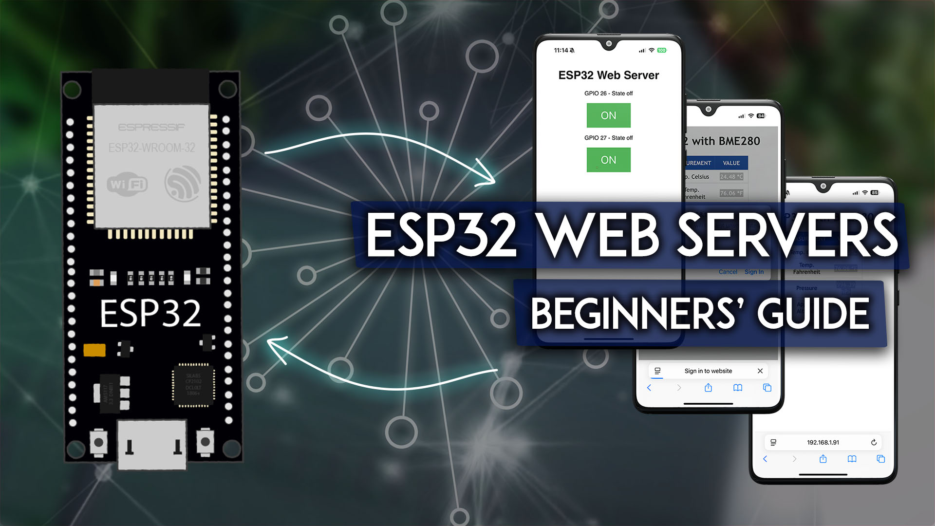
New to ESP32 web servers? This guide cover everything need to know to build web servers with the ESP32, you can control and monitor its outputs remotely with Arduino Core
rose cobalt
Thanks
 cosmic forum
Hi,
want to connect a USB keyboard to a single board (USB-C for power/ programming + USB-A for the keyboard) and capture/modify keystrokes in real time so they can be entered directly into standard applications like Notepad or Word. I'm looking for recommendations on which RP2040/RP2350 boards and libraries support USB host mode without additional adapters
cosmic forum
rose cobalt
I have some ideas for projects I want to do, for example, an analog clock with a...
You can use Raspberry Pi Pico W [or better 2W]
minor snow
cosmic forum
Hi,
want to connect a USB keyboard to a single board (USB-C for power/ programm...
Use the board recommended in this Adafruit Learn Guide: https://learn.adafruit.com/diy-turbo-button-controller-hid-remapper
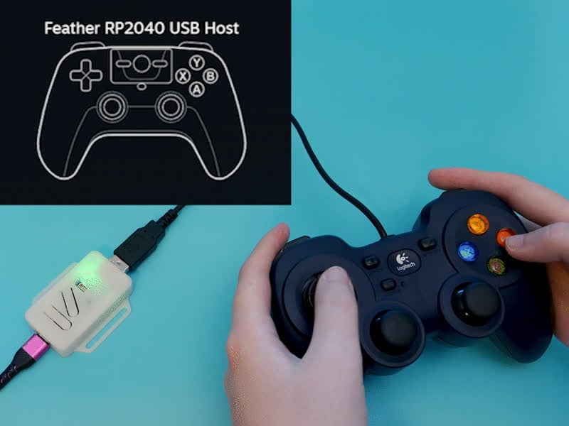
Save your thumbs with a turbo button
 swift yew
Hello! I have two questions about this Lithium Ion Battery Pack - some people want to use it with our Project.
Lithium Ion Battery Pack - 3.7V 6600mAh
https://www.adafruit.com/product/353
First: it's a JST-PH connector, and therefore has a 2.0mm pitch, correct?
Second: can you confirm the polarity - red plus, black minus?
I can't find it on the product page directly, just inferring from how the JST connectors are connected / labelled on other boards, like here:


Need a massive battery for your project? This lithium-ion pack is made of 3 balanced 2200mAh cells for a total of 6600mA capacity! The cells are connected in parallel and spot-welded to a ...
buoyant jackal
swift yew
Hello! I have two questions about this Lithium Ion Battery Pack - some people wa...
yes 2mm pitch. Red means +, black means -.
NOTE that battery packs sold by other vendors may have the power wires in reverse order. ALWAYS check the polarity. All Adafruit packs sold have the same polarity and match the PH sockets on our boards.
 mystic surge
Is the appropriate place to ask about Neotrellis debugging. Mine just stopped functioing but the small LED in the middle of back flashes about once every 5 seconds. The other LED near it occasionally flashes white/blue (color blind issues) and then 4-5 flashes in another color. Are there and suggestions how to get it working again. It has been great for many years and John Parks code works great. Thanks
cosmic forum
minor snow
Use the board recommended in this Adafruit Learn Guide: https://learn.adafruit.c...
Thank you very much 👍
And can I convert the complete micropython/circuitpython code to UF2 without using sdk?
swift yew
buoyant jackal
yes 2mm pitch. Red means +, black means -.
NOTE that battery packs sold by othe...
perfect, thank you @buoyant jackal! our project (a synthesizer DIY kit) has a polarity check built in, I hope that effectively keeps people from reverse-connection their battery packs.
I hope the Adafruit pack works well for our first testers, and then we can recommend getting that one to people building one in the US.
minor snow
cosmic forum
And can I convert the complete micropython/circuitpython code to UF2 without usi...
Technically, you can do that using picotool: https://github.com/raspberrypi/picotool?tab=readme-ov-file#save
However, I'm not sure if that's the best way to do that. See: https://xyproblem.info/
cosmic forum
minor snow
Technically, you can do that using `picotool`: <https://github.com/raspberrypi/p...
Thank you. I will investigate the availability of additional solutions
thin raft
just curious, if i got a powerboost 1000, is there a way to hook up a usb-c port to it (like through a breakout board) instead of using the microUSB or should i just get a adapter cable
minor snow
thin raft
just curious, if i got a powerboost 1000, is there a way to hook up a usb-c port...
I don't know about that, but Adafruit makes a similar product with USB type-C and a terminal block: https://www.adafruit.com/product/6106

We're always on the look out for better ways to make projects portable: being able to charge your battery in the most convenient manner will let projects run no matter what power is ...
thin raft
oh neat
was just trying to figure out a way to make a portable pi 5 handheld thing
and while the powerboost is great i dont wanna depend on micro usb lol
minor snow
thin raft
was just trying to figure out a way to make a portable pi 5 handheld thing
The Raspberry Pi 5 requires quite a bit of power: https://www.raspberrypi.com/documentation/computers/raspberry-pi.html#typical-power-requirements
Your best bet might be a portable power bank.
thin raft
ahh
the goal was for like a gaming handheld thing, just googled it and found that someone apparently made a project similar to what i'm aiming for already https://github.com/SquishyAWP/Pi-Deck-5

GitHub
A Pi 5 based handheld purpose built for retro videogame emulation. - SquishyAWP/Pi-Deck-5
im new to this kinda stuff, but it seems like the power system is a few diff boards?
4 18650 cells (Unprotected)
1 HW-391 BMS (HX-2S-D20 suitable sub)
1 Mini560/ Mini560 Pro 5V Buck converter
1 LX-LISC-V2 15w Type C 2s fast charging board
my current build right now to keep everything together is just a regular Pi 5 in a pibow coupe 5 case, along with a hyperpixel XP screen in the GPIO pins and screwed to the pi.
for form factor, was planning to aim for a 3D printed game gear-esque design so I could have a bit of interior room instead of something slim like above. (fan of bulk handhelds like that as someone who has a steam deck/rog ally)
usin this project to bascially learn everything at once and i mostly got the coding and stuff down, it's just down to the other stuff like power/audio n all that and then figuring out how to put it all together. its a fun little first major project
Already have blender 3D modeling knowledge, but no cad knowledge, so I’m taking this opportunity to learn this cad software called plasticity that’s made for 3D modeling peeps. Managed to print a cool fake game gear front for it on my first day figuring it out

i realize im kinda rambling tho now lol. I thought about using a CM5 nano board of some kind, but i can't find one that does GPIO for the display and keeps the form factor small.
oh wait, this one finally exists now, even has a audio jack which i was planning to use for the audio dac https://www.waveshare.com/cm5-nano-b.htm
Nano Base Board (B) for Raspberry Pi Compute Module 5, Same Size As The CM5 | CM5-NANO-B
worn apex
Hi all banging my head trying to get a KB2040 wired to a 2.4” Touchscreen TFT and could have sworn my wiring is correct but even after following the guide here: https://learn.adafruit.com/adafruit-2-8-and-3-2-color-tft-touchscreen-breakout-v2?view=all#circuitpython-displayio-quickstart and swapping out the CS, DC, and RST pins for D4-6 on my KB2040
I’m still just getting a white screen. Any ideas on what I’m messing up here 🙁
 upper bloom
thin raft
im new to this kinda stuff, but it seems like the power system is a few diff boa...
upper bloom
thin raft
im new to this kinda stuff, but it seems like the power system is a few diff boa...
While I’m sure someone has tested and validated this design, I would recommend against using unprotected lithium cells unless you have significant experience handling these. Protected cells shouldn’t cost that much more…
thin raft
yeah seems like a good idea
im assuming the blue wrapping on these mean they're protected right https://www.adafruit.com/product/5035

Lithium-ion (also known as 'liion' or 'li-ion') batteries are thin, light, and powerful. The output ranges from 4.2V when completely charged to 3.7V. This battery has a ...
(still learning everything from scratch so makin sure. im not comfortable with doin stuff like wiring batteries together due to the dangers n stuff.)
lusty wind
thin raft
im assuming the blue wrapping on these mean they're protected right https://www....
The blue wrapping means nothing. What you are looking for is this: “Includes the necessary protection circuitry.”
 austere thorn
Hi Adafruit people,
I have finished my game console and it is being used at the hospital I work at. I just have a few bugs i cannot squash. The board I made has a 80pin rp2350b and for the past month it was being perfect and i was able to program over SWD with another pico with the picoprobe firmware. But suddenly in this last week it stopped working over SWD
it is very intermittant. I trtied narrowing t down but the issue keeps moving around. I used a brand new board, brand new pico probe, nuked flash, triple made sure wiring was good, and tried different computers
but i just cannot get swd to work
again
it uploads fine over usb but thats not debuggable
I tried to revert to the old pico probe firmware but no luck. And I am 100p sure my wiring is not the issue. I have connected it correctly. Gp2 to SW clk and Gp3 to SWIO with gnd and power.
I am stuck and this is my last week at my coop, any help or suggestions would be appreciated.
So far i have tried reverting to different versions of my code, the sdk, the probe firmware, and even soldering down the wires. No Luck!
It works once in a while on a random board and then stops.
Open On-Chip Debugger 0.12.0+dev-gebec950-dirty (2024-09-27-16:29)
Licensed under GNU GPL v2
For bug reports, read
        http://openocd.org/doc/doxygen/bugs.html
Info : Hardware thread awareness created
Info : Hardware thread awareness created
Info : Hardware thread awareness created
Info : Hardware thread awareness created
cortex_m reset_config sysresetreq
Info : Using CMSIS-DAPv2 interface with VID:PID=0x2e8a:0x000c, serial=8FF39319B774079E
Info : CMSIS-DAP: SWD supported
Info : CMSIS-DAP: Atomic commands supported
Info : CMSIS-DAP: Test domain timer supported
Info : CMSIS-DAP: FW Version = 2.0.0
Info : CMSIS-DAP: Interface Initialised (SWD)
Info : SWCLK/TCK = 0 SWDIO/TMS = 0 TDI = 0 TDO = 0 nTRST = 0 nRESET = 0
Info : CMSIS-DAP: Interface ready
Info : clock speed 5000 kHz
Error: Error connecting DP: cannot read IDR
in procedure 'program'
** OpenOCD init failed **
shutdown command invoked
^ Thats my ocd output
 indigo skiff
Hi all!
I'm building an outdoor solar-powered sculpture designed to strike a gong at high noon each day, triggered by a photosensor. I'm seeking help from someone with electronics knowledge to talk me through the detailed wiring process for my new power system and solenoid activation circuit.
My anticipated essential components are:
– Solar Panel: A 5-10 Watt, 12V panel to collect solar energy.
– Charge Controller: An absolutely necessary 12V unit specifically for Li-ion batteries to prevent overcharging or deep discharging.
– Battery: An 11.1V (3S) Li-ion pack (3000-5000 mAh) chosen for its energy density and stable voltage for 24/7 operation.
– Buck Converter: An LM2596 module is crucial to efficiently convert the battery's 11.1V to a stable 5V for the microcontroller.
– Linear Solenoid: A 12V push-type solenoid capable of 10-15 Newtons of force to strike the gong.
– Relay Module: A 5V Single Channel Relay is needed for the Arduino to safely switch the high-current solenoid.
– (I already have: ) Microcontroller: An ELEGOO UNO R3 (basically an Arduino) and a photosensor (3.3V-5V).
The battery then powers two main circuits: the high-current solenoid via the relay, and the low-power microcontroller and photosensor via the buck converter (outputting 5V). — I particularly need guidance on connecting the charge controller to the solar panel and battery, correctly wiring the buck converter's input and output, and integrating the relay module with the battery, solenoid, and the Microcontroller . Any expertise in helping me connect these components safely and effectively would be greatly appreciated!
minor snow
austere thorn
I tried to revert to the old pico probe firmware but no luck. And I am 100p sure...
Are the GND connections of the Pico that's being used as a Debug Probe and the RP2350B connected to each other?
austere thorn
yes
I soldered all the wires togather actually
i thought it waas the female duponts i was using
but ot isnt
i will reflow the chip today
maybe there is bad solder
minor snow
austere thorn
I soldered all the wires togather actually
Umm… GND, SWDIO, and SWCLK should not be connected (more specifically should not be shorted) together into a single bundle. Make sure to reference the wiring diagram in the "Debug with a second Pico or Pico 2" section of Appendix A of Getting started with Raspberry Pi Pico-series.
buoyant jackal
austere thorn
Hi Adafruit people,
I have finished my game console and it is being used at the...
can you reduce the SWD clock rate?
austere thorn
minor snow
Umm… GND, SWDIO, and SWCLK should *not* be connected (more specifically should *...
not what mean lol i meant i soldered them to theor respective pins
austere thorn
buoyant jackal
can you reduce the SWD clock rate?
i havnt tried this but its currently at 5khz
buoyant jackal
austere thorn
i havnt tried this but its currently at 5khz
we don't use SWD much on RP2xxx. You might ask in https://forums.raspberrypi.com/ or the (not so active) unofficial Pico discord
all the grounds are tied together properly? Everything is soldered, etc.?
austere thorn
yes everything soldered, just wondering how do you debug on your platforms? do you do "burn and learn"?
buoyant jackal
we log using print statements mostly
austere thorn
ah
buoyant jackal
if we are really stuck we'll use gdb, but we don't usually need to go there.
we used it a lot more when debugging SAMD chips
logging both in C and Python
austere thorn
thats still effective. I just like the convienience of swd, i dont have to move to get it into usb bootloader
austere thorn
buoyant jackal
we don't use SWD much on RP2xxx. You might ask in <https://forums.raspberrypi.co...
i will post on forums
but i will also try to replace the chip
austere thorn
okay i confirmed it was the chip
a different untouched board programs fine now


i think i blew up the swd peripheral with esd
(i am starting to believe in esd straps now)
 dusk hedge
does anyone know if the usb a ports on a rasberry pi 5 can be configured as OTG? so i can use it as a usb device instead of host
worn apex
worn apex
Hi all banging my head trying to get a KB2040 wired to a 2.4” Touchscreen TFT an...
Bumping this if any kind souls please could let me know what’s wrong. Is this a question for Discord or Adafruit support, by the way?
 floral hinge
Quick question on the MacroPad RP2040: Can I display unicode characters on the OLED? I want to display 🔇 if possible. I know i can do it as an image, but it would be a lot easier to do it as text. 😄
buoyant jackal
worn apex
Bumping this if any kind souls please could let me know what’s wrong. Is this a ...
Is it our touchscreen?(which one?) If so you could bring it up in https://forums.adafruit.com. Did you see any errors in the REPL output?
Also see https://learn.adafruit.com/adafruit-2-4-color-tft-touchscreen-breakout/troubleshooting
Sometimes a white screen is due to the display cable not being seated properly in the connector. You can flip up the latch on the connector, reseat the cable carefully, and then flip it back down to lock
 brisk rain
floral hinge
Quick question on the MacroPad RP2040: Can I display unicode characters on the O...
brisk rain
floral hinge
Quick question on the MacroPad RP2040: Can I display unicode characters on the O...
The new lvfontio module should enable this. It loads characters from the filesystem as needed
I added it for emoji support
floral hinge
brisk rain
The new lvfontio module should enable this. It loads characters from the filesys...
This sounds awesome! Where can I find docs?
brisk rain
For use with terminal: https://docs.circuitpython.org/en/latest/shared-bindings/lvfontio/index.html#module-lvfontio
 bright fractal
dusk hedge
does anyone know if the usb a ports on a rasberry pi 5 can be configured as OTG?...
bright fractal
dusk hedge
does anyone know if the usb a ports on a rasberry pi 5 can be configured as OTG?...
no, I don't believe the USB-A ports can be configured in device mode on the pi 4 or 5. you can use the USB-C power port in device mode, but since the pi 5 is power-hungry, you'll probably need to use a USB-C splitter to inject power from a separate adapter, and run only data lines and ground to your host device.
dusk hedge
bright fractal
no, I don't believe the USB-A ports can be configured in device mode on the pi 4...
yeah okay, thats a shame but its better then nothing
thanks!
worn apex
buoyant jackal
Is it our touchscreen?(which one?) If so you could bring it up in <https://forum...
It’s this one! https://www.adafruit.com/product/2478
I’m not certain my code is correct either because I’m using a KB2040 which has a different pins than the example. Would it help to post my code here or in the forums?

Add some jazz & pizzazz to your project with a color touchscreen LCD. This TFT display is 2.4" diagonal with a bright (4 white-LED) backlight and it's colorful! 240x320 pixels ...
buoyant jackal
worn apex
It’s this one! https://www.adafruit.com/product/2478
I’m not certain my code is...
It is easy to make mistakes in the wiring, with so many wires, or to have a bad connection. Triple-check the wiring, check the socket on the back like I suggested. Also make sure there are no errors reported in the REPL. Then ask again if needed in #help-with-circuitpython or the forums.
worn apex
buoyant jackal
It is easy to make mistakes in the wiring, with so many wires, or to have a bad ...
I will check the socket, unsure how to adjust it but will try. My code is here for reference using a KB2040 from adafruit:
import board
import displayio
import terminalio
from adafruit_display_text import label
from fourwire import FourWire
from adafruit_bus_device.spi_device import SPIDevice
from digitalio import DigitalInOut # Import DigitalInOut

import adafruit_ili9341

print("CODE nowread")

# Release any resources currently in use for the displays
displayio.release_displays()

spi = board.SPI()
tft_cs = board.D4
tft_dc = board.D5

display_bus = FourWire(spi, command=tft_dc, chip_select=tft_cs, reset=board.D6)
display = adafruit_ili9341.ILI9341(display_bus, width=320, height=240)

# Make the display context
splash = displayio.Group()
display.root_group = splash

# Draw a green background
color_bitmap = displayio.Bitmap(320, 240, 1)
color_palette = displayio.Palette(1)
color_palette[0] = 0x00FF00  # Bright Green

bg_sprite = displayio.TileGrid(color_bitmap, pixel_shader=color_palette, x=0, y=0)

splash.append(bg_sprite)

# Draw a smaller inner rectangle
inner_bitmap = displayio.Bitmap(280, 200, 1)
inner_palette = displayio.Palette(1)
inner_palette[0] = 0xAA0088  # Purple
inner_sprite = displayio.TileGrid(inner_bitmap, pixel_shader=inner_palette, x=20, y=20)
splash.append(inner_sprite)

# Draw a label
text_group = displayio.Group(scale=3, x=57, y=120)
text = "Hello World!"
text_area = label.Label(terminalio.FONT, text=text, color=0xFFFF00)
text_group.append(text_area)  # Subgroup for text scaling
splash.append(text_group)

while True:
pass```I also checked the soldering and did a continuity test on every joint I used and that passed so I don't think it's the soldering either.
Also, I’m not sure how to remove the cable it looks permanently attached to me:
 buoyant jackal
worn apex
buoyant jackal
worn apex
could you take a picture of the back of the board?
then take a picture of the wiring that's clear enough to see which wire is going where (are you using a breadboard?)
worn apex
buoyant jackal
could you take a picture of the back of the board?
I realized I might be able to ply the FPC connector off but I had no luck and didn’t want to force it. Will take a few pics of the wiring shortly
buoyant jackal
worn apex
I realized I might be able to ply the FPC connector off but I had no luck and di...
there is a flap on the connector on the board that flips up. It only takes a gentle tug open it after you open any locks on the connector. But I would want to see a picture to verify
worn apex
buoyant jackal
there is a flap on the connector on the board that flips up. It only takes a gen...


Here’s the two pics requested. I don’t have enough colors here for the jumper wire so you’ll have to follow the path of the wire. The expanded picture makes it easier to see!
buoyant jackal
worn apex
The highlighted black things are the connector locks. You slide them a short distance (like 1-2mm) with your fingernail to unlock them, horizontally, toward the "adafruit" on the board. That will loosen the cable so you can slide it in or out of the connector and reseat it. When done, push them back in place On this connector I think there is not a flap that flips up. But the cable doesn't look crooked, which is often a reason for "all white" on the display. Don't bother to do this yet until I (and you) check the connections.
 buoyant jackal
worn apex
buoyant jackal
worn apex
Looks like you didn't solder the jumpers closed to put the board into SPI mode: see https://learn.adafruit.com/adafruit-2-4-color-tft-touchscreen-breakout/spi-wiring-test
note you solder IM1,2,3, NOT IM0
Read the guide throughly
so don't mess with the connector now 🙂
worn apex
buoyant jackal
Looks like you didn't solder the jumpers closed to put the board into SPI mode: ...
Ah let me try that later. I jumped ahead to the wiring part. Darn! Sorry for wasting your time. Let me re-read the full guide and then solder those jumpers and let me get back you later today or early tomorrow (soldering still takes me some time haha)
buoyant jackal
np!
you can skip the "parallel" page, look at the SPI page
if you have them, use red for +V and black for gnd on jumpers as a convention
worn apex
buoyant jackal
you can skip the "parallel" page, look at the SPI page
For the purpose of a quick test (I have to go in a bit) can I just use jumper to connect 3v to IM1, IM2 and IM3 to test this for now
If not will solder when back!
buoyant jackal
you could try, but holding them in place reliably is going to be difficult
one side of the jumper is 3.3v (from the on-board regulator) and one side goes to the chip
i don't think you have to be in a hurry on this. do it right
worn apex
buoyant jackal
i don't think you have to be in a hurry on this. do it right
I’ll just hold off. Don’t want to do this wrong way and short something! Thank you may not be back until tomorrow but I appreciate your help. I have never successfully desoldered anything correctly (though I tried lol) but the guide makes it clear to me that IM1, IM2, and IM3 are the only ones to be soldered
I do have some chipquick desolder now thankfully never used it yet!
 worn apex
Well, the instructions aren't as clear on how to set up the touchscreen with CircuitPython, but I've got touches registering, at least. If there's a good guide on setting that up, happy to read it
 lilac flint
I need 15 more SparkleMotion 6100 boards. Adafruit is out but digikey has them. I thought I read the board went through an update. Is this true and if so is there a way to know if I order from, digikey I’m getting the latest hw? Thx!
I am also distributing pixelblades to students and want max flexibility to swap in three wire neopixel and four wire dot star connectors. These boards aren’t designed for adding a terminal block to. Is it ok to solder pin/male headers then rig up pigtail ends with socket/female ends on 3 and 4 wire jsts and just swap sockets when I want different lights? I know in larger installs I’ll drop board VIN for separate power. Or would you do a diff setup?
 minor furnace
Hi, could someone help me increase the power output on a CH334F or recommend something? Hoping this might work, any thoughts?
 marsh bridge
lilac flint
I need 15 more SparkleMotion 6100 boards. Adafruit is out but digikey has them. ...
marsh bridge
lilac flint
I need 15 more SparkleMotion 6100 boards. Adafruit is out but digikey has them. ...
Maybe stick question in ask an engineer. Not sure there's any rev info for digikey, but your enquiry made me finally find a transcript search engine:
https://filmot.com/search/Sparkle+motion+microphone/1?channelID=UCpOlOeQjj7EsVnDh3zuCgsA&sortField=uploaddate&sortOrder=desc&gridView=1&
leading here https://www.youtube.com/live/aRgjbQCMkCE?si=1gpY0oyNaIu6-AJf&t=300
I also love the screw terminals on everything, even soldering them sideways (inline with PCB) if necessary and reinforcing with hot glue. You could just solder wires straight on though as you suggest. I similarly have the larger black locking connectors (3/4pin jst?) that come with some panels as a bag of those cable pairs is pretty cheap. Running extra power lines too like you say for easier daisy-chaining, and all pulled wires get hot glue (the black siliconey one).
buoyant jackal
lilac flint
I need 15 more SparkleMotion 6100 boards. Adafruit is out but digikey has them. ...
Here is a description of how the original boards were modified: https://forums.adafruit.com/viewtopic.php?p=1053600 Read the whole thread. A pin was lifted. My guess is that the Digi-Key stock is OK, but you could ask support@adafruit.com. We tend to make small run to begin with and sell it only through our store to make sure it's OK before distributing it more widely
buoyant jackal
lilac flint
I am also distributing pixelblades to students and want max flexibility to swap ...
did you mean "pixelblazes". I don't know what "pixelblades" are.
You can buy 0.1' inch pitch screw terminals: https://www.adafruit.com/search?q=0.1+pitch+terminal+blocks
I see multiple "pixelblazes". You could do the pin-to-jumper thing you are thinking of, or solder prewired JST's to the holes
Sparkle Motion Stick and Mini Sparkle Motion are in stock in our store
buoyant jackal
minor furnace
Hi, could someone help me increase the power output on a CH334F or recommend som...
A PC is not going to supply 3A on a USB-C port. I am confused about what you want to do here. Why do you need to supply high current from the CH334F? Is it just for wiring convenience? What you are you powering at 5V high amps?
white marsh
buoyant jackal
Here is a description of how the original boards were modified: <https://forums....
Dan, curious if the schematic & artwork for the Sparkle was corrected. I ask because if it hasn't and the pin is still being lifted then it would be easty to check if a board was fixed or not. However if they artwork was changed so you guys don't have to add the extra step of lifting the pin, then the pin not being lifted would no longer be a good indicator or a problem board.
buoyant jackal
white marsh
Dan, curious if the schematic & artwork for the Sparkle was corrected. I ask bec...
The guide schematic has not yet been corrected. I will add a warning box.
white marsh
buoyant jackal
The guide schematic has not yet been corrected. I will add a warning box.
Right, but what I mean is, are you guys still lifting that pin on the latest builds rather than changing the design? If you are, then checking for the lifted pin is a good indicator of a corrected board.
buoyant jackal
white marsh
Right, but what I mean is, are you guys still lifting that pin on the latest bui...
no, we've revised the circuitboard to have a no-connection. The pin-lifting was to deal with the small amount of stock that was rev A.
I think you could test for continuity between pin 5 and the line +24V line
white marsh
buoyant jackal
no, we've revised the circuitboard to have a no-connection. The pin-lifting was ...
Ok that is what meant. So we can't suggest to people to check the IC if the board is corrected because the new ones won't have a lifted pin and are correct.
buoyant jackal
a very small number in the very first batch shipped did not have the pin lifted. we offered those people replacements or said they could just lift the pin
white marsh
buoyant jackal
a very small number in the very first batch shipped did not have the pin lifted....
OK so like you said, a continuity check is that best check now then.
buoyant jackal
yes, I don't see a rev mark on the silkscreen.
 wet bison
How much voltage can these litz wires I pulled out of a SMPS transformer handle?

I want to twist them into stranded pairs and use them to carry the voltage out of a half bridge inverter. The inverter output should be 180Vac or 380V P-P I’m afraid the twisted pair of litz cable will cry for dear mercy before it arcs.
I have high voltage testing gear. Maybe I can just try a 1KV hi-pot? That won’t tell me if it experiences corona though.
260KHz-320KHz.
Asking more that there’s some other degenerate grimy Tesla Coiler in here who have tried.
wet bison
I managed to twist them together with the little pre-cut pieces of heat shrink.

 jade matrix
I'm trying to design a custom pcb to sodder a feather and a 1.54" tri color eink display onto it. I found a footprint file for the feathers but i can't find one for the display.
marsh bridge
jade matrix
I'm trying to design a custom pcb to sodder a feather and a 1.54" tri color eink...
Do you mean the breakout version [with or without eyespi connector]? Maybe you can use the pcb files / diagrams to make what you need: https://learn.adafruit.com/adafruit-1-54-eink-display-breakouts/downloads
lusty wind
wet bison
How much voltage can these litz wires I pulled out of a SMPS transformer handle?
I think you will find that advice on this server will not be forthcoming as discussion of this topic would be in violation of Adafruit's Code of Conduct (#code-of-conduct), specifically, "Discussion or promotion of activities or projects that intend or pose a risk of significant harm". If you don't know what you're doing, you clearly shouldn't be messing around with voltages in the range of 180VAC. You're certainly free to do things on your own (assuming you're willing to take such huge risks to yourself and those around you) but you can't get that kind of help here.
wet bison
I am industrial technician I work on 3MW power inverters. Sorry.
urban sequoia
https://learn.adafruit.com/upgrading-esp32-firmware/upgrade-airlift-firmware-using-rp2040 I'm trying to flash Bluepad32 to my Airlift board but it keeps not connecting, despite the Pico appearing as "Board CDC" on COM14.

Keep the firmware on your ESP32 AirLift WiFi-BLE Co-Processor up-to-date!
Here’s my wiring. I’ve double checked, but I’ve messed up my wiring in the past. The airlift does work - I tested it with the stock firmware - I just want to change that firmware.
 marsh bridge
urban sequoia
Here’s my wiring. I’ve double checked, but I’ve messed up my wiring in the past....
marsh bridge
urban sequoia
Here’s my wiring. I’ve double checked, but I’ve messed up my wiring in the past....
It looks like you're missing the Airlifts GPIO0 (Zero) connection from this list, labelled GP0 on silkscreen:
Pico GPIO13 to Airlift CS
Pico GPIO16 to AirLift RST
Pico GPIO9 to AirLift GPIO0
Pico GPIO0 (TX) to Airlift RX
Pico GPIO1 (RX) to AirLift TX
(Plus power/gnd)
It's necessary to put the airlifts esp32 chip into bootloader / download mode.
 urban sequoia
marsh bridge
It looks like you're missing the Airlifts GPIO**0** (Zero) connection from this ...
urban sequoia
marsh bridge
It looks like you're missing the Airlifts GPIO**0** (Zero) connection from this ...
Ahh that makes sense, I don’t know how I missed that
Thanks
 astral crane
I'm having trouble with a cat peeing in a corner of the carpet
Is there a way to either:
- detect the presence of the cat in a specific area of the room
- detect the presence of water over a large section of floor (like along the entire wall)
?
(I want to play a loud sound if I detect she's peeing there)
lusty wind
astral crane
I'm having trouble with a cat peeing in a corner of the carpet
Is there a way to...
You can get cheap microwave detectors that work over several meters and detect living things, even through (wooden) walls to a limited degree.
astral crane
I wonder if maybe an RFID collar?
lusty wind
astral crane
I wonder if maybe an RFID collar?
Range is in centimeters at best.
fleet terrace
It'd be easier to passively detect when something is in the corner versus actively trying to detect something like a RFID collar
astral crane
Dangit
fleet terrace
with a camera and a Pi you could use machine learning to detect when it is the cat
astral crane
Maybe pair a microwave animal detector with a
astral crane
fleet terrace
with a camera and a Pi you could use machine learning to detect when it is the c...
Yeah that
lusty wind
The microwave sensors cost a few dollars, are easy to use and relatively foolproof.
fleet terrace
Edge Impulse probably has examples with microcontrollers
astral crane
The idea is to scare the crap out of the cat when she gets near those spots
So i do need to be able to detect when it's her vs other pets
lusty wind
astral crane
The idea is to scare the crap out of the cat when she gets near those spots
So i...
Ah, other pets. Then you need an AI camera trained with photos of the specific animal. But that won’t work at all in dim or no light.
You’re probably better off using a more primitive solution like cat repellent.
astral crane
lusty wind
You’re probably better off using a more primitive solution like cat repellent.
I'm working on that too
Concentrated vinegar wasn't enough
And i tried using a spray i had accidentally bought, but it's for outdoors and is too strong
I can still taste it
This cat is the most persistent animal i have ever had the trouble of owning
astral crane
lusty wind
Ah, other pets. Then you need an AI camera trained with photos of the specific a...
I can keep the lights on
All the animals have different coat patterns
And i have a boatload of pictures of them all
ML might be viable
lusty wind
astral crane
I can keep the lights on
All the animals have different coat patterns
And i have...
Is there really a problem in scaring the other animals away from that corner? I’m guessing that the current smell of pee is enticing to the cat so cleaning it thoroughly and probably a citrus spray may make it unappealing to her.
A technological solution might be fun but there are probably easier and more effective ways to handle this
astral crane
lusty wind
Is there really a problem in scaring the other animals away from that corner? I’...
I've been doing this
This gremlin still pees there
 lusty wind
astral crane
I've been doing this
This gremlin still pees there
lusty wind
astral crane
I've been doing this
This gremlin still pees there
Highly motivated
Then a proximity detector plus a loud noise might be your best bet.
A microcontroller, a VL53L1X and an MP3 player board with built-in amplifier would cost about $30
buoyant jackal
astral crane
I've been doing this
This gremlin still pees there
With our cat, we used spiky barriers and sticky tape, with limited success. Simply blocking off the area and/or putting a litter box nearby also helped somewhat. She was old and blind.
lilac flint
buoyant jackal
Sparkle Motion Stick and Mini Sparkle Motion are in stock in our store
This - yes PixelBlaze 🙂 I've got a bunch of these for this semester for students to experiment with. We want to get the full Sparklemotions. I think I bought the last 7. We'll get more when they arrive. We'll e sure to let yuou know if the "Festival of Light" runs. Would love to have you stop by if you're available & interested. Still working out deets.
buoyant jackal
lilac flint
This - yes PixelBlaze 🙂 I've got a bunch of these for this semester for student...
i'd love to see it!
I don't have an answer for your bsky query re PixelBlaze identification, but since they are not our boards, I would say ask the original manufacturer directly.
minor snow
lilac flint
This - yes PixelBlaze 🙂 I've got a bunch of these for this semester for student...
At the time of writing, DigiKey has 25 of these in stock: https://www.digikey.com/en/products/detail/adafruit-industries-llc/6100/25981344

DigiKey Electronics
Order today, ships today. 6100 – ESP32 ESP32 MPU Embedded Evaluation Board from Adafruit Industries LLC. Pricing and Availability on millions of electronic components from Digi-Key Electronics.
lusty wind

 cunning horizon
lusty wind
cunning horizon
lusty wind
Those are some nice wheels 🙂
lusty wind
cunning horizon
Those are some nice wheels 🙂
Ack, apologies. I seem to have done it again somehow. I've accidentally cross-posted from my phone to the Personal Robotics server and somehow, #help-with-projects on Adafruit. I blame my phone. It's my phone's fault.
In any case, this is my new KRZ04 robot, a mostly goBILDA chassis and Mecanum wheels on its first dry run: https://youtu.be/LJNyLS2tU-o?si=p6YH1bMmqH8JWyFO
 spring kite
Hello!
I'm having issues trying to use a micro SD card with Circuit Python. Curious if anyone can help!
I have an SD card socket on my PCB that I'm trying to get working. After 5ish hours of failing, I thought it might be better to use an SD card reader breakout that I have.
I am trying with this circuit Python code that Chat GPT gave me this script which hangs forever:
spi = board.SPI()
while not spi.try_lock():
    pass
spi.configure(baudrate=400000)

cs = board.A3
try:
    sd = sdcardio.SDCard(spi, cs)
    vfs = storage.VfsFat(sd)
    storage.mount(vfs, "/sd")
    print("Mounted successfully!")
except Exception as e:
    print("Mount failed:", e)
I also tried the Adafruit tutorial which results in RuntimeError: Mount point directory missing.
https://learn.adafruit.com/micropython-hardware-sd-cards/circuitpython
Any ideas?
Also if anyone is super interested in all the other things I tried, it's in this thread.:
On my PCB, I first thought it was an electrical issue with MOSI which seemed to have a weak solder joint under magnifier. I reflowed it and added solder, no change.
I formatted my 32GB SD card as FAT32.
I tried an entire stack of SD cards, some with files on it, some blank.
I bought a BRAND NEW 32GB card, no change.
I cried in frustration. No change.
In every scenario, I checked all connections with a multi meter before running any code.


 cunning horizon
spring kite
Hello!
I'm having issues trying to use a micro SD card with Circuit Python. Cu...
cunning horizon
spring kite
Hello!
I'm having issues trying to use a micro SD card with Circuit Python. Cu...
Some dude had the same issue with a camera. Check this out, I think it will do the trick.
https://forums.adafruit.com/viewtopic.php?t=207813
cunning horizon
lusty wind
Ack, apologies. I seem to have done it again somehow. I've accidentally cross-po...
I don't think you need an excuse to share 😉
Was that ready made it did you design it?
lusty wind
cunning horizon
I don't think you need an excuse to share 😉
Was that ready made it did you des...
The apology was mostly because I'd not planned to post the photo here, and because it's also in the wrong channel. But since we're here...
I've been building robots for awhile now, so this was an attempt to gather all the best things about my previous robots into a new design, something I could use as a robust experimental platform. I wanted it to be as compact as possible and yet still have most of the essential features of its predecessor, a smaller Mecanum wheeled robot, e.g., the Makita battery clipped into its center, and also using a combination of a Pi and STM32. I knew the design would be using goBILDA parts for the chassis and wheels, and given they provide the STEP files, I did the original plan in OnShape, which also provided the BOM for the parts.
 cunning horizon
lusty wind
The apology was mostly because I'd not planned to post the photo here, and becau...
cunning horizon
lusty wind
The apology was mostly because I'd not planned to post the photo here, and becau...
Pretty interesting. So what kinda pi you got in there and what can it do? I'm trying to make SLAM robot. Inspired by GPTars. Still need to get SLAM working and find a faster TTS :p

All the hardware is there and I got it working but integrating it all together... Plus I'm new at ROS. I assume you use Ros aswel if you've been building robots
lusty wind
cunning horizon
Pretty interesting. So what kinda pi you got in there and what can it do? I'm tr...
Actually, you might be surprised to find that I'm using a Pi Zero 2 W, and that I don't use ROS at all. But that's because my goals are possibly different than yours. I've been investigating Behaviour-Based Robotics, which is somewhat adverse to location mapping, and I also wanted to build my own "robot OS" (called KROS), so while BBR is possible using ROS, it has a great deal of overhead I didn't need. Most of KROS is written in Python on the Pi now but I'm gradually trying to move more and more over to MicroPython on the STM32, so at some point the Pi will be there mostly as an ssh connection and for high-level control.
I like the look of your robot. So apart from the ultrasonic sensor, what else are you using for SLAM? I think I can see a LiDAR on the roof.
cunning horizon
lusty wind
Actually, you might be surprised to find that I'm using a Pi Zero 2 W, and that ...
Thanks . And i was hoping to run slam all through lidar. I noticed that slam does like encoders but my motors do not have them. Was planning on using the ultrasoon just to prevent it from running of edges and falling
by aiming it down. And yeah the amount of stuff you need just to control a simple motor... It does make me question ROS sometimes xD
So what does KROS stand for? :p
lusty wind
cunning horizon
So what does KROS stand for? :p
My first version was actually called "ROS" but that clearly was going to be confusing. My robots have all been in the "K" series so I just shoved a K in front. I can't right now even remember what the K stands for. One of my earlier K bots was inspired by the DPRG's David Anderson, who has an SRO4. My robot was therefore the KR01. I suppose this is somewhat like asking why car companies choose their model names... 🤔
lusty wind
cunning horizon
Thanks . And i was hoping to run slam all through lidar. I noticed that slam doe...
I don't think the ultrasonic will help much for that, not good at short range and not reliable due to echoes. You might try the small ToF sensors like Pololu sell, They've got both digital and PWM (distance) versions, and a short range (50mm) digital one aimed down at front would probably work. you'd just have it return a 1 so long as it could see the floor, or even an line-following array, which is what some tabletop robots use to keep from plummeting. I'd never trust my own hardware and software with the life of my robots so they live on the floor.
You definitely need odometery if you're doing SLAM. Motors usually come in a fairly standard form factor. It's very likely you can replace your motors with either ones with an encoder built-in, or ones with an extended back shaft that you could use to mount your own encoder. Another alternative would be optical, but that can take up a fair bit of space and you're (generally) running that off the wheel axle rather than the motor shaft, with corresponding lack of resolution.
cunning horizon
LoL my original message had the word stuff replaced with a form of p00p but it was to much and the server blocked the message xD we are raising a generation of soft shelled people xD
For what I've researched one should be able to SLAM without Odom. It might drift and stuff and that is fine. I just want to get it working and learn from it. If the drift is to much, or I have time and money left over, I might put encoders in it just for the experience.
lusty wind
cunning horizon
For what I've researched one should be able to SLAM without Odom. It might drift...
There is one other possibility you might find both helpful and interesting: you could use an optical flow sensor. Depending on the distance, that'd either be a PWM3901 (longer distance, 80mm+ up to flying drone height) or a PAA5100JE (robot vacuum distance) to provide an x,y measurement of movement across the ground. This works great so long as the ground your robot is on is relatively the same in terms of physical appearance, as an OFS uses a tiny low-res camera, an edge algorithm, and returns movement. They're kinda cool, Pimoroni sells both as SPI devices.
cunning horizon
lusty wind
There is one other possibility you might find both helpful and interesting: you ...
With the shi.... I mean stuff I'm using a PAA5100JE might be pretty cool and better then encoder. But still first I have to get slam to map something in ros xD I got the lidar software/firmware running but I just do not see a map form in rviz
Adding a sensor/data won't help if I have nothing being build to start with 😉 I'm just to new. But I'll order me one of those for sure 🙂
 crystal kayak
I'm working on a CircuitPython base system for helping non-programmers incorporate interesting and complex interactive effects into their projects. The current example I'm working on is basically an RC vehicle - 4 fixed driven wheels (each with a DC motor) and a web UI that lets you drive it with a virtual joystick in a browser page. Since (at least this example) isn't meant to support autonomous movement, it doesn't have to have all the sensors to keep it from bumping into things, driving off the edge of a table, etc (although they would be nice). BUT even if it had all those, there's always a time during the development where your logic isn't using them properly yet, or you get direction's reversed, or... Similarly, even with manual control, if my example doesn't properly handle the joystick input or detect loss of connection to the browser and leaves the motor running, my little project could trying driving somewhere it shouldn't...
I came up with a very simple (obvious in hindsight) solution for this, at least during development phase. Since there's a dedicated connection from the +5v power source to the motor DC input on my dc motor controllers, I just made a simple tether out of dupont jumpers to physically cut power to the motors if it strays too far from wherever the other end of the tether is attached.


Probably not a great choice for most "finished" mobile projects, but a hopefully useful hack for minimizing motion madness before your firmware's finished.
crystal kayak
lusty wind
There is one other possibility you might find both helpful and interesting: you ...
I admit I haven't thoroughly searched yet, but are you aware of any I2C (ideally Stemma QT) non contact (proximity/TOF/...) distance sensors with fast sampling (like the the PAA5100JE/PMW3901 at less than 10msec per / 100+ FPS but I2C instead of SPI)?
lusty wind
crystal kayak
I admit I haven't thoroughly searched yet, but are you aware of any *__I2C__* (...
As I'm sure you're aware, optical flow sensors aren't distance measurement sensors, and the ones I've cited are both SPI devices because of the need for higher bandwidth processing (because they have small cameras on board).
If you're really in need of high speed distance sensors I'd just avoid I2C entirely and go with something like either the digital (on-off) or PWM (distance-sensing) Pololu sensors.
Their newer models replace older ones based on Sharp IR sensors, the new ones actually have ST ToF sensors on board. I can't speak as to whether their performance is sufficient for your requirements, but the specs are clearly there on the product page, i.e., depending on type and model they have update rates of between 30-142Hz. It's the nature of these sensors to take a certain amount of time to do their job, so it's not the communications protocol that's really the bottleneck, but getting I2C out of the way means you're dealing with the sensor pretty directly.
The PWM versions emit a continuous stream, with the duty cycle representing distance. I've used both the digital and PWM versions and they work very well.
https://www.pololu.com/category/283/pololu-digital-distance-sensors

Lidar-based distance sensors with simple digital interfaces for detection of nearby objects. Options are available with maximum ranges of a few centimeters to a few meters.
crystal kayak
I'll keep that in mind for other projects, but for this one SPI/PWM are not a good fit. One of the key strategies my current project uses to keep things "beginner friendly" is a focus on shield style expansion boards (like FeatherWings) and StemmaQT/Qwiic modules to eliminate the need for more intermediate/advanced skills in physical (wiring) and virtual (pin assignments, etc) specification. AFAIK the Feather form factor has SPI pins reserved, so creating a FeatherWing breakout for an SPI device should be straightforward (expect maybe for assigning CS), but the physical positioning requirements might make that less than optimal (as opposed to an external wired I2C/SPI device where the sensor can be placed separately from the controller).
lusty wind
crystal kayak
I'll keep that in mind for other projects, but for this one SPI/PWM are not a g...
I'm not quite clear what your requirements are. If you're using Qwiic connectors you're using I2C and therefore limited by the performance of your I2C bus. I don't uise CircuitPython myself, but generally speaking you can set the speed of your I2C bus to whatever is the maximum permitted by your hardware. Myself, I've never really noticed a problematic lag in I2C performance for my robots. Robots in general, since they are physical devices, can't possibly changes as fast as the electronics, i.e., even in 2025 a lot of people run 20Hz control loops on their bots, which is entirely sufficient.
I didn't comment previously on your idea of a tether, but it's pretty common in hobby and university-level competition robotics to have a kill switch (sometimes a big red button) somewhere on the robot that simply cuts power to either the entire robot, or to just the motors. There's also a pin-in-socket connected to a string, such as a barrel connector: you pull out the connector and the power is cut off. The only issue with those is that you must have the string pulled in the direction of the connector, even a bit sideways and it won't pull out. Running the string through an eyelet in front of the connector solves this one.
I've just finished a motor controller board and I added exactly that, a break between the controller and the motors that will be connected with a physical switch.
crystal kayak
The tether I described is a simple variation on the "pin-in-socket connected to a string". But since it's using flexible jumper wires which would extend outside of the vehicle a bit to provide the "socket" (twin dupont sockets) (as opposed to a fixed socket on the chassis) and the two pins are not mechanically joined, I think it should be mostly immune from binding-when-pulled-sideways issues. I'm also not surprised that this is common knowledge in robotics communities - as I said it's obvious in hindsight but I spun my wheels a while before realizing this would work, so given the recent conversations on various sensors for autonomous vehicles I figured it might be helpful to share.
marsh bridge
crystal kayak
Those optical sensors look pretty sweet. I've experimented with a few similar...
Did you try upping the i2c bus speed as some of the ToF ones support pretty quick. Not sure the max but often i2c is run at 100k and could instead be 400k or even 1Mbps which some sensors support.
As well as of course picking one with suitable refresh rate...
crystal kayak
Did you try upping the i2c bus speed as
 dusty helm
hello! :). Can anyone tell me what this connector for the power switch on the Raspberry Pi 5 is called?
 lusty wind
dusty helm
hello! :). Can anyone tell me what this connector for the power switch on the Ra...
lusty wind
dusty helm
hello! :). Can anyone tell me what this connector for the power switch on the Ra...
They're a type of JST connector, a JST-SH (1.0mm between the pins).
spring kite
cunning horizon
Some dude had the same issue with a camera. Check this out, I think it will do t...
Wow..... I thought a mount point to /sd meant that I need to make an /sd folder on the SD card......
I didn't realize it was on the circuitpy drive itself. That is so confusing.
noble fossil
it's a holdover from Unix. mountpoint are regular directories (typically in the root directory) until they're mounted over (and then any normal contents they previously had are usually hidden until the unmount)
spring kite
A sad way to loose 5 hours. But a lesson I won't forget. Thanks everyone.
 slow abyss
Hi! Dunno if it's really a hardware or software problem but would anyone be willing to lend a hand to debug my RPI Pico + RYLR998 LoRa thing I'm trying to build? The receiver device works fine, but the sender side keeps disconnecting (crashing?) when I try to send LoRa messages in a loop (even with a generous 8s wait in-between):
import time
import board
import busio
import digitalio

lora = busio.UART(tx=board.GP16, rx=board.GP17, baudrate=115200, receiver_buffer_size=0)

led = digitalio.DigitalInOut(board.LED)
led.direction = digitalio.Direction.OUTPUT


def init_lora():
    lora.write(bytes("AT+NOIDEA\r\n", "ascii"))
    time.sleep(3)
    lora.write(bytes(f"AT+BAND=868500000\r\n", "ascii"))
    time.sleep(3)

def send(msg, adr=88):
    lora.write(bytes(f"AT+SEND={adr},{len(msg)},{msg}\r\n", "ascii"))
    time.sleep(8)
    lora.readline()

def blink():
    for t in range(5):
        led.value = True
        time.sleep(0.2)
        led.value = False
        time.sleep(0.2)
    led.value = False

def receive_and_transmit():
    while True:
        print("Waiting for data...")
        line = serial.readline().decode().strip()
        if line:
            blink()
            send(line)
            print("Sent over LoRa:", line)

init_lora()
receive_and_transmit()
Also added a pic of the breadboard layout.
Mind you, I'm really new to IoT, so stupid things are bound to happen 🙂 Thanks!
 lusty wind
slow abyss
Hi! Dunno if it's really a hardware or software problem but would anyone be will...
lusty wind
slow abyss
Hi! Dunno if it's really a hardware or software problem but would anyone be will...
You might try wrapping your core functionality in a try-except-finally loop, printing out the error message along with a stack trace. That way you can see what's actually going wrong.
slow abyss
Hmm, looks like it crashes, disconnect before it can print out the exception ...
lusty wind
slow abyss
Hmm, looks like it crashes, disconnect before it can print out the exception ...
If the crash happens inside a try-except compound statement, it will always get to the except block.
import traceback
try:
    # your code
    # something TERRIBLE happens
    # it never gets to here
except Exception as e:
    # but it does get to here
    print('{} raised: {}'.format(type(e), e))
    traceback.print_exception(e) # prints a stack trace
 cunning saffron
How do you reconnect after it crashes? It would be really unusual for code this simple to cause a hard fault. What version of CircuitPython?
fleet terrace
slow abyss
Hi! Dunno if it's really a hardware or software problem but would anyone be will...
Why are you disabling the receive buffer?
It would also be helpful to describe what "crash" means to you.
slow abyss
fleet terrace
Why are you disabling the receive buffer?
sorry, this was a remnant of 'throw things at the code until something works' 🙁
as for the crash - i was connected via the red usb cable and reloading code from tio. it typically looked like this: sent a few messages, then tio reported that the connection got disconnected and reconnected again. i'm currently also trying to find a way to control the code via some other UART connection
cunning saffron
when tio reconnects, has the code restarted? is there any indication of an exception or a hard fault?
white marsh
slow abyss
as for the crash - i was connected via the red usb cable and reloading code from...
I think what @fleet terrace was asking and I have the same question, does disconnecting and reconnecting again mean only to the receiver (USB connector to computer is fine)? Or do you mean the board actually resets and you lose USB connector to your computer momentarily.
For the former, stays connected to the computer, your try...except statements can include a lot of print statements to show you what it is doing. With the latter, disconnecting from the computer's USB, that is more of an issue because then usually any print statements don't happen so you can not see your troubleshooting print statements.
cunning saffron
you can use a safemode.py file if it's hard faulting https://learn.adafruit.com/circuitpython-safe-mode, or check supervisor.get_previous_traceback() if there's an unprinted exception https://docs.circuitpython.org/en/latest/shared-bindings/supervisor/index.html#supervisor.get_previous_traceback
white marsh
cunning saffron
you can use a `safemode.py` file if it's hard faulting <https://learn.adafruit.c...
OH I wasn't aware of the safemode.py option. Good to know for future needs.
cunning saffron
I like to save extra info from safemode.py and boot.py https://gist.github.com/anecdata/fe35dc6a94069fc920edf61a64750b53
 snow idol
hey all, fairly new to microprocessors and VERY new to circuitpython. currently i'm trying to get a set of neopixels to run through 4 different light patterns, which are cycled via a capacitive touch input. the current issue i'm facing is that some of the patterns aren't able to cycle while they're ongoing (namely the ones that use for loops and time.sleep() statements). everything i'm reading says that if i want to have an external input interrupt an ongoing loop i need to use async commands, which currently isn't possible since i'm using a Gemma M0. is there a more clever way to do this that isn't asynchronous?
buoyant jackal
snow idol
hey all, fairly new to microprocessors and VERY new to circuitpython. currently ...
you can poll for the cap touch input by checking for it after each call to .animate().
(BTW, better to ask CircuitPython questions in #help-with-circuitpython )
snow idol
buoyant jackal
you can poll for the cap touch input by checking for it after each call to `.ani...
this helped, thanks! i was calling for the mode change within the main loop rather than calling it in the individual functions which seems to have fixed my problem
any other issues i'll mention in the python channel sorry about that!
 open kraken
anyone over here have recent success in getting a RP2040 Thinkink to talk to the adafruit 7.5" Tricolor E-Ink Display?
I've been struggling, and wonder if I have something simple screwed up. Have worked the associated guides to no avail... Been doing it with circuitpython, but about to abandon to try the arduino route....
lusty wind
 blissful plover
I have no experience with any of these devices, but one thing that is a common gotcha on those ribbon connectors (e.g., the Pi camera) is getting them reversed in their socket. You might check that against any existing documentation just to be sure that's not the case here.
blissful plover
I verified that the side of the FPC with the pads matches the side of the connector with the contacts.
hybrid crag
blissful plover
I haven't played with that particular dev board so not sure if the pinouts match what you'd expect? like if you try flash an LED on the pin - does it function normally? more of a sanity check than anything else to make sure that 17 actually matches 17, for example
blissful plover
Hm, that's a good idea. I'll try that.
hybrid crag
their examples show A17 in their Arduino file, where the one you posted was just 17
blissful plover
hybrid crag
I haven't played with that particular dev board so not sure if the pinouts match...
I just tested it with a button and verified that pins 17 and 18 match their labellings on the silkscreen.
 tranquil flare
Is anyone using the Zephyr RTOS with Adafruit products, e.g. feather boards like the ESP32S3? Wonder if there is place to go to chat about getting the board device trees correctly defined.
warm jay
Got a bit of a specific question once again.
I need to fold a small flex PCB at 180° - right now I am fixing it with double sided tape. But the flex PCB wants to naturally unfold so after some time the double sided tape does not hold well anymore.
I was thinking of just using some solder to fix that flex PCB on a metal frame.
The problem here is that the metal frame is overmolded with some plastic underneath. So in theory I cannot go over 240°C temperature otherwise the plastic will deform.
So the next option would be to use low-temp solder. ~140°C
I read that low temp solder is not so strong(?) - but would it be strong enough to just hold the flex PCB down? Or how is the strength measured of low temp solder?
 lone tree
in my experience, low temp solder is strong enough, so I expect it will work fine.
But soldering something to a metal frame is hard.
first, solder doesn't stick well to steel - or is your frame brass?
second, unless your frame is made out of thin wires, it will act as a massive heat sink, so heating one place to high temperature will be hard.
Why not just use some epoxy?
lusty wind
lone tree
in my experience, low temp solder is strong enough, so I expect it will work fin...
unless your frame is made out of thin wires, it will act as a massive heat sink, so heating one place to high temperature will be hard
I agree entirely. A soldering iron would struggle to heat up the frame enough to get the solder to flow at all, even if the surface is suitably clean, not oxidised, and covered in flux.
warm jay
it's a thin stainless steel sheet.
Around 6x6x0.2 mm
Yes I thought about epoxy but it's a bit messy 😬
And IF I ever need to remove it it's impossible
lusty wind
warm jay
Yes I thought about epoxy but it's a bit messy 😬
And IF I ever need to remove ...
I've used industrial-quality velcro for a variety of things. The glue on the back sticks very well to smooth surfaces and it's not permanent. The various grades of velcro have some that are extremely strong.
thin raft
question:
I also have a dead nvidia Gsync monitor that won't boot (Asus PG279Q), i am assuming due to the gsync card being killed. If the gsync card doesn't load, it doesnt boot.
people online have said this is a very common cause of its death and it involves buying a repalcement board, which is hard and expensive to come by.
I tried to figure out the panel, and it lead me here, saying its a tft-lcd: https://www.panelook.com/M270Q008_V0_AUO_27.0_LCM_overview_41810.html
does anyone know what kinda tech i would need to make a monitor from this dead one? or should i just get a new one (the main problem being the next cheapest one of that quality is like, $250)
it's just a very good 1440p 144hz IPS monitor and i don't wanna trash it.
buoyant jackal
thin raft
question:
I also have a dead nvidia Gsync monitor that won't boot ([Asus PG279Q...
often there is a power-supply board and a separate display controller board. It's possible the power supply board failed, which would be easier to fix.
But getting some other non-exact-replacement display board that has the specs you want and would work with the panel is probably expensive as well, and it would have to fit in the case, etc.
 nocturne beacon
Im and a friend are building a small 2pl game system that the main feature are an andotrope display ( A 2d display thats being displayed from all angles by using rotation) . The current plan is using an raspberry pi 3 model B, two RA8875 Driver Board(part from adafruit) and two 7.0" 40-pin TFT Display(part from adafruit) and also a 12 wire slip ring to connect the drivers to the Raspberry. The problem is that buying two drivers and displays are quite expensive and the slip ring only take around 300 rpm(according to Adafruit´s prduct description) and we would need it to rotate at about 450-500 rpm. Are there any clever ways to lessen the cost and still make it work? The games that we're think of programing are pong, tron, flappy bird(simple games). We alredy have an raspberry 3 model B from another project, so swapping raspberry wont reduce the cost.
upper bloom
nocturne beacon
Im and a friend are building a small 2pl game system that the main feature are a...
A quality esp32-s3 is half the price of an ra8875. You’ll have to write some firmware to get it to work like the ra8875, but if you’re worried about project cost over development resources, it’s worth considering. (Did I mention its wireless capabilities? Hmmmmm…)
If the displays are showing the same image at the same time, I wonder if you can design a custom splitter cable to drive two displays with one driver…
I can see a slip-ring-less solution with inductive power and wireless communication with a qualia board, but the development work required to achieve that is no trivial matter.
lone tree
nocturne beacon
Im and a friend are building a small 2pl game system that the main feature are a...
can you put all electronics, including battery, in the rotating part, and communicate with game controller witelessly? that would solve the slip ring problem
nocturne beacon
upper bloom
A quality esp32-s3 is half the price of an ra8875. You’ll have to write some fir...
How should I conect the two 40 pin ribboncables from the displays to the Esp32-s3 ? I can´t se a good soulution
upper bloom
nocturne beacon
How should I conect the two 40 pin ribboncables from the displays to the Esp32-s...
You’d probably need to design a custom splitter flex pcb for this purpose. It’s pretty niche and I don’t know if anyone else has done it before, but you can probably get a batch made for abut the same if not less than a second driver board.
I guess using a battery and connecting wirelessly would make for a much simpler setup. It does mean you would have to charge the battery between uses but it’s probably cheaper than a high-speed slip ring and simpler than inductive power.
normal roost
I have a project question. I've been tasked with doing a hide and seek kind of thing.
What would I possibly need to have a light turn on when it got close to something.
Like a proximity switch kind of thing
lusty wind
normal roost
I have a project question. I've been tasked with doing a hide and seek kind of t...
How close is close?
normal roost
@lusty wind bout 20 feet
lusty wind
normal roost
<@828135237744984114> bout 20 feet
And second question: can this be line of sight, where you could use light, or is the hidden object potentially inside of something else, where you'd need some kind of radio waves that can penetrate things? Note that radio waves will not penetrate metal objects, so if the object is hidden in a metal container or behind a metal panel you won't be able to sense it.
normal roost
It will be in a plastic container. I'm hoping to find something around 5v that uses microwave radio signals
Probably not doable with the constraints, but worth a try to loom
lusty wind
normal roost
It will be in a plastic container. I'm hoping to find something around 5v that u...
The microwave sensors I've seen are single units designed to detect warm bodies and/or bodies in motion, the kind of thing used in doorway openers. I've not seen a transmitter/receiver pair at a hobby level. You could use something like a 433MHz tx/rx pair, but I'm not sure if you can measure signal strength with the software, which is what you need to determine distance. Another option would be to use a pair of ESP32 microcontrollers, hook them up via ESP32 Now or ESP32 Mesh as a pairing, as you can measure signal strength between them. None of this will be very accurate, but if you're okay with roughly 20 feet it might work. Very much an experiment though, as there'll be a lot of variables.
https://www.aliexpress.com/item/1005008429007449.html
normal roost
I just thought of a perfect solution to my issue. Car Key Fobs. I can just grab one of those
lusty wind
normal roost
I just thought of a perfect solution to my issue. Car Key Fobs. I can just grab...
How are you going to measure distance with one of those?
normal roost
Won't have to. It's going to be about 90 acres of land they have to find it on.
lusty wind
normal roost
Won't have to. It's going to be about 90 acres of land they have to find it on.
Well, you know your requirements better than I, but in an open space that car key fob's range will be a lot greater than 20 feet.
normal roost
Yep. I just want it to light up when it's near. But having the mox make a loud noise will do just fine when they have to trek 90 acres for a treasure hunt game
lusty wind
normal roost
Yep. I just want it to light up when it's near. But having the mox make a loud n...
So the key fob at one end, what at the other?
normal roost
The end of the relay. Along with another puzzle

Instructions on how to configure the RF Remote Control Relay from Experience Lights. www.experiencelights.com
lusty wind
normal roost
https://youtu.be/TaFx7ShRcWE?si=Hx_PuAmI05nRg7TJ
Sounds like you've got it sorted then.
normal roost
lusty wind
Sounds like you've got it sorted then.
Appreciate the help with brain storming. Gonna hook this up to a feather.
 normal roost
When dealing with Arduino's, i'm assuming that if i have a buttong that is independant from the main on/off button, I.E 'Button 2' is wired to say, Pin A1. 3v into the button, Ground into button.
stating that, does the button just close the circuit between the 3v to Pin A1 allowing all 3v to get sent to Pin A1 or does the board only let 1V go to it.
this is just a general question i'm trying not to fry $50 here
my goal here is to wire the 3.3V pin from a Propmaker Featherwing, to this Micro Relay Switch, Micro relay switch "Momentary V out, to Input Pin on the Featherwing. the relay acting as a button or switch. when the Wireless remote is pressed, something happens.
question is, do i need to put a resistor before the Output for the relay to prevent frying a board.


first time dealing with anything that might need a resistor
 craggy sigil
normal roost
first time dealing with anything that might need a resistor
craggy sigil
normal roost
first time dealing with anything that might need a resistor
I'm too new to tell you for sure either, and I'm not sure linking youtube is kosher, but I watched a recent video titled "Turn anything into an Arduino Module: Reusing everyday electronics" that I believe touches on your question. He also had a device with a secondary button he ended up making a voltage divider for iirc
For my project, I picked up one of those cheap led lights with a lens and was thinking I'd wire it to a sparkle motion mini, but I don't know where ground is? I'm assuming the obvious G is green?
 craggy sigil
hmm. ohmed out the inline controller board. gnd from the usb plug isnt connected to anything.. incl the unpopulated pad marked gnd
oh. looking at strips they dont have a v- either. well ok then
 high chasm
I'm planning to make a simple IoT temp sensor with the QT Py ESP32-S2 and AHT20 breakout board. If I'm planning on it taking samples pretty sparingly, like every 5 min, any recs for what size lipo battery I should use? I don't know what's realistic, but charging once a month or less would be ideal.
buoyant jackal
high chasm
I'm planning to make a simple IoT temp sensor with the QT Py ESP32-S2 and AHT20 ...
you can get some idea here: https://learn.adafruit.com/deep-sleep-with-circuitpython/power-consumption
high chasm
that's super helpful, thanks
normal roost
anyone know if i need a resistor between this and the M4 Feather/Prop-Maker Feather wing Input Pin?
It says its pushing out 1-12V but im guessing thats depending on the amount of input (Which will be from the 3.3V output pin on the feather.)

 hallow wadi
I'm not sure what that is, but a resistor is generally not the solution to a voltage mismatch
fleet terrace
normal roost
anyone know if i need a resistor between this and the M4 Feather/Prop-Maker Feat...
what is it?
normal roost
It's a wireless relay switch. Basically a key car fob sensor
lusty wind
normal roost
It's a wireless relay switch. Basically a key car fob sensor
Without a schematic it's pretty much just guessing what to do with it.
normal roost
Okie dokie, guess my plan will either work, or fry my feather. But I'm sure the output voltage won't be an issue
lusty wind
normal roost
Okie dokie, guess my plan will either work, or fry my feather. But I'm sure the ...
I have no idea why you'd be sure of that. I'm more or less rather certain, given even the little I can see, that you'd more likely fry your Feather than it actually working. Guessing with electronics seldom if ever works.
normal roost
Well, it works just like any other switch it just uses the 3.3 v for the raid capability. All the other manual switches I have hooked up that bridge the 3.3v connection on the board haven't had any issue.
lusty wind
normal roost
Well, it works just like any other switch it just uses the 3.3 v for the raid ca...
If you were so sure, then why did you ask the question on this channel?
normal roost
I wanted to be 100% but now I'm in the "F*** it I'm trying" it phase
lusty wind
normal roost
I wanted to be 100% but now I'm in the "F*** it I'm trying" it phase
Well, I'm sure I'm not alone in saying that you're still very well within the "F*** it I'm trying it" phase. If you're willing to risk frying your Feather board, then go ahead, but absent a schematic I think this is all just wishful thinking. My read is that if you're replacing a physical switch with a Feather then you're going to fry the Feather if it gets hit with more than its maximum supply voltage, or 3.3V on any pin. At least that's what it seems you're trying to do, correct me if I'm wrong, none of anyone here can quite tell absent any more information than you've provided.
Put it this way: the device is unknown. Absent a schematic you're just guessing. Guessing in electronics usually leads to blue smoke.
gritty birch
FOLO: feathers only live once
normal roost
Yea I realize that, I just can't find a schematic on it. I've got 4 other backup feathers so if this doesn't work It will be fine.
dusky lion
It looks like a latching relay, controlled by a 433mhz receiver.
I wonder if 3v will be enough to energize the relay, given (from the diagram) it's marked as a 4.5v part.
If you want to be extra safe, just power up the top connectors to the power inputs, test with the key fob, and use a multimeter to check connectivity between the bottom pair of connectors.
Maybe double check which connector wires actually power the module, the color code on the wires may be unreliable.
normal roost
it works. 75 foot range too
or at least it works drawing 3.3v from the prop maker feather wing
thin raft
Is there any way to add RCA to a pi5? Seems like there’s solutions for pi 3/4 but not for 5. Just trying to make a lil emulator on a pi5 right now while I wait for my fpga consoles to manifest
fleet terrace
thin raft
Is there any way to add RCA to a pi5? Seems like there’s solutions for pi 3/4 bu...
This Pi Forum thread seems relevant: https://forums.raspberrypi.com/viewtopic.php?t=362182
 tender warren
Possibly elementary question about using the ADS7830 - what's the 'correct' way to break out the ground line for multiple lines? I don't plan to put it on a breadboard. I could make a breakout cable, but that seems inelegant.
lusty wind
tender warren
Possibly elementary question about using the ADS7830 - what's the 'correct' way ...
There's no "correct" way to do this, it all depends on your project requirements, skills, etc. If you mean you don't want to put it on a breadboard, do you mean a solderless breadboard? Because there is an alternative, called Perma-Proto boards, which match a solderless breadboard's layout. And you can also cut one of them into smaller pieces with a hacksaw, sand the edges with sandpaper, etc. You could in theory create a socket for the ADS7830 and mount it on the Perma-Proto, and then mount the latter in your project housing/enclosure.
https://www.adafruit.com/product/1608

Customers have asked us to carry basic perf-board, but we never liked the look of most basic perf: it's always crummy quality, with pads that flake off and no labeling. Then we thought ...
tender warren
lusty wind
There's no "correct" way to do this, it all depends on your project requirements...
I'm looking for a fairly compact way to break it out in a permanent way, since I'll be installing it inside a small case (which I'll be designing and 3d printing) to insert inside a larger project). Maybe that Perma-Proto is the way to go. Thanks.
lusty wind
tender warren
I'm looking for a fairly compact way to break it out in a permanent way, since I...
I've for years cut them into all sorts of shapes, sometimes just large enough to extend a few pins, leaving room for a mounting hole or mounting them to something with industrial velcro. Wear a mask if you're cutting or sanding them as you don't want glass fibers in your lungs.
Another option that might sound outlandish but is actually not might be to actually design a custom PC board using Kicad and having it manufactured. Over the past few months I've learned how to do that, and JLCPCB's prices are surprisingly cheap for the 5 board minimum. A series of boards has massively reduced the number of wiring harnesses on my most recent robot.
I designed all the PC boards in the photos, except for the STM32 board on top and the Pi Zero 2 W.


So I kinda graduated from using Perma-Proto boards on my previous robots to custom PCBs now. It's also kinda fun.
dusky lion
lusty wind
So I kinda graduated from using Perma-Proto boards on my previous robots to cust...
Very cool 😎 it looks like you also added a name seal to the decorative bottom, nice.
normal roost
gritty birch
lusty wind
Did you design your own silkscreens?
white marsh
normal roost
The commentary that went with the video was perfect. I understood it completely. Neat device that I will have to keep in mind if I ever need to activate something remotely.
lusty wind
dusky lion
Very cool 😎 it looks like you also added a name seal to the decorative bottom, ...
That’s the kanji for Furusato.
lusty wind
gritty birch
Did you design your own silkscreens?
Yes, the images come from a 1908 Arts & Crafts era book “Nature and Ornament” by Lewis F. Day. I bought it many years ago and always loved the designs.
gritty birch
looks nice!
lusty wind
A package arrived in the post this morning, so I even today I had occasion to use a piece of Perma-Proto to mount a large capacitor to buffer my robot's power supply (so I can flip the switch between battery and external supply without rebooting). And yes, I did choose that Elna cap because it was on sale and it was a nice shade of what, fuchsia? 😄
 tender warren
lusty wind
So I kinda graduated from using Perma-Proto boards on my previous robots to cust...
tender warren
lusty wind
So I kinda graduated from using Perma-Proto boards on my previous robots to cust...
Hah. Nice. I actually did do that a couple years ago as a one-off project to make what's essentially an adapted version of the AW9523 that carries connectors compatible with the Light My Bricks connectors.
 sturdy rampart
I apologize if this is the wrong thread.
I wanted to ask...for a portable project, has anyone been able to find a commonly available fuel gauge and lipo charger combo that is small for MCUs?
minor snow
sturdy rampart
I apologize if this is the wrong thread.
I wanted to ask...for a portable proj...
All Adafruit Feather boards have an on-board LiPo charger, and most have instructions within their Adafruit Learn guide on how to read the battery voltage.
cunning saffron
@sturdy rampart I don't know what you consider small, but there's also things like this https://www.adafruit.com/product/5580
sturdy rampart
minor snow
All Adafruit Feather boards have an on-board LiPo charger, and most have instruc...
This is for a board that is not from Adafruit. They don't have a board in the same size, so I had to get it from another vendor.
 gentle cobalt
Looking to place an Adafruit order and trying to pack as many projects' parts in as I can for free shipping, how would I go about making something like this?
https://www.youtube.com/watch?v=iQLSvE31dbk
Years ago I handmade ceramic pumpkins that each member of my family carved into jack-o-lanterns, and they're my favorite things I've ever made, and it just occurred to me the other day that I could make them better by adding lights and music and making a pumpkin patch choir. Problem is I don't know how, hence why I'm here asking for some direction.
Thank you!

Ken Wingard creates the perfect platform to display Hallmark’s new Snowmen Bell Choir in your home.
Get more Home & Family How-To's here: http://www.hallmarkchannel.com/home-and-family/how-to
sturdy rampart
cunning saffron
<@1371453936317366305> I don't know what you consider small, but there's also th...
I have seen this product. It does not fit the requirements. If anyone else has a sugestion, I'd love to hear it. Please and thank you.
buoyant jackal
sturdy rampart
I have seen this product. It does not fit the requirements. If anyone else has a...
could you point to the board you are using, and say what the size requirements are?
white marsh
gentle cobalt
Looking to place an Adafruit order and trying to pack as many projects' parts in...
Oh oh oh, Idea! No idea how to implement it but Espressif has ESP-NOW which allows ESP board to talk to each other over WiFi directly. A learning guide thing here https://learn.adafruit.com/esp-now-in-circuitpython/ but I wonder if you can use ESP based board in your projects and if they can talk to each other directly without needing to be on a wifi network, one could trigger others to do things. Like at Halloween if someone on your porch touched any ONE of your decorations, they could all scream in response. 😃

Easy, direct, low-power wireless on ESP32 boards
lusty wind
white marsh
Oh oh oh, Idea! No idea how to implement it but Espressif has ESP-NOW which allo...
If you read the documentation you'll find that ESP32-Now (as well as ESP32 Mesh) enable ESP32 devices to communicate peer-to-peer (or peer-to-mesh), without a router. This is also well-supported in MicroPython (indeed, I hadn't yet heard that it was supported in CircuitPython).
gentle cobalt
@white marsh @lusty wind
That looks really promising...
I know nothing about chip specs or really much of anything about the things that Adafruit sells, I just desperately want to learn ("ooh shiny", and I'm an engineering student who really ought to understand some of this stuff).
If you know, do I understand correctly that this board supports that protocol, and would it be able to/what else would it need to be able to drive LEDs, play music (stored or streamed), and communicate with a network of > 4 of them? It's the smallest and cheapest attached to that article.
https://www.adafruit.com/product/5426
Thank you for talking to me about it!

The ESP32-S3 has arrived in QT Py format - and what a great way to get started with this powerful new chip from Espressif! With dual 240 MHz cores, WiFi and BLE support, and native USB, this ...
lusty wind
gentle cobalt
<@1208917307716280371> <@828135237744984114>
That looks really promising...
I k...
This doesn't really have anything to do with Adafruit, who are like many others in using Espressif's chips to manufacture their boards. All ESP32 chips that support WiFi support ESP32-Now.
- All microcontrollers can drive discrete LEDs, though there are strict limits on the total current that can be supported. If you're talking about RGB LEDs or LEDs that use more than normal, you'd need a driver. But one or two simple LEDs, yes.
- As for playing music, that's a whole subject of discussion, but in short, no, not without an amplifier. There are I2S amps on the market, but if you want to play music you might want to just control a dedicated player as they're cheap, often come with a built-in amp, and are easy to interface with. I've not had great success with I2S sound players but they are available.
- If you want to intercommunicate between more than two ESP32s you are no longer talking peer-to-peer (ESP32-Now), you're talking ESP32-Mesh, which is a different thing. ESP32-Mesh is not supported on the S2 (because it doesn't support ESP-IDF).
Time to do some reading! 😄
gentle cobalt
lusty wind
This doesn't really have anything to do with Adafruit, who are like many others ...
I just said “I don’t know much about the stuff Adafruit sells” as a catch all for “controllers and drivers and boards and sensors and lions and tigers and bears” and so on. The stuff you need to make techy gizmos more complicated than a blinking light.
I was thinking RGB LEDs for a customized light show effect, so I need to look into drivers.
For music, look into independent music players that the microcontroller can just give orders to. Do you have any recommendations or places to look off the top of your head? Unless maybe I want to do something more complicated with the sound data in which case I might need a more capable microcontroller?
The one I linked is the S3, which does look like it supports ESP-IDF?
Thank you again
sturdy rampart
could you point to the board you are
minor snow
Have you considered getting the Adafruit Fruit Jam as an alternative? It can emulate the Commodore 64: https://learn.adafruit.com/mcume-emulators-on-fruit-jam/c64-emulator

Relive bygone eras with a collection of retro emulators for the Fruit Jam
gentle cobalt
@lusty wind Please stop me if I'm asking (or ever do ask) for too much help, but would the ESP32-S3 be able to drive one of these without extra stuff?
https://www.adafruit.com/product/302
Also, based on what I'm reading about mcd ratings, they look like they'd individually be bright enough to light up a knick-knack, does that sound right? And would "warm white" be achievable as one of their color settings or would that need to be a separate LED (I'm seeing things that make me think both ways)?

Diffused 5mm tri-color LEDs with separate red, green and blue LED chips inside! Nice indicator, and fun to color-swirl. 60 degree viewing angle. We like diffused RGB LEDs because they color ...
lusty wind
gentle cobalt
<@828135237744984114> Please stop me if I'm asking (or ever do ask) for too much...
I should probably say you are in a Discord server. Ask the server not an individual.
gentle cobalt
lusty wind
I should probably say you are in a Discord server. Ask the server not an individ...
My apologies, you're who I was talking to so I just naturally continued. I don't have much experience asking questions in a chatroom environment like this
gentle cobalt
gentle cobalt
<@828135237744984114> Please stop me if I'm asking (or ever do ask) for too much...
Ok then, to anyone who's willing and able to give me their two cents, same questions about these LEDs. Thanks!
P.S. Let me know if there's something I should move to a different channel for
cunning saffron
@gentle cobalt you'll need a resistor of appropriate value for each color lead.
re: "warm white" ...depends how picky you are. you could probably make a slight yellow/orange color, but at lower light levels there is less control of color. I really don't think you're going to get anywhere near a 2700°K with CRI of 90 out of it.
gentle cobalt
cunning saffron
<@300394540345458699> you'll need a resistor of appropriate value for each color...
I'm not terribly picky, I just want the ability to make it the equivalent of a tea light and don't yet have the judgement to tell if fudging the RGB or getting a second, discrete warm white LED would be better. And flickering/brightness would just be a matter of changing the signal to the LED, right?
lusty wind
gentle cobalt
My apologies, you're who I was talking to so I just naturally continued. I don't...
No apologies necessary, but a lot of your questions are answerable with the materials you have at hand. You're asking people to do that work for you. I provided quite a lot of information about the ESP32 and spent my time trying to help, but you've got to do your part too. The specs for the various ESP32 chips are widely available, and the maximum current per pin plus the maximum current for the entire device is published on each datasheet. What you're doing is asking me to go and look that up for you.
I suggested that you need an LED driver, and you linked an LED product which even mentions the driver that Adafruit recommends: "We carry and use CA more than CC because multi-LED driver chips (such as the TLC5940/TLC5941) are often designed exclusively for CA and can't be used with Common-Cathode."
There's also another style of RGB LED that is nowadays more common, the family of single-data line devices such as the WS2812, commonly called a NeoPixel. These still require a driver, or if the device is under the current limits of a pin, at least a level shifter (your microcontrollers all operate at 3.3V logic but most RGB LEDs at 5V).
So if you want to become an engineer you probably need to learn how to read datasheets, it's an absolutely necessary skill. I'm not trying to give you a bad time. and the habit of asking other people for help when the materials are available may be motivated simply by wanting to connect with other people (I entirely understand that), but that has to be balanced by also doing one's own research.
If you want to simply make a single LED "tea light" you need none of this, as a microcontroller pin can drive a single discrete LED with no difficulty (again, the datasheet is your friend: you choose an LED to use less current than the pin can provide, or you use a driver). There are companies that sell LEDs in very specific colors, like one company sells maybe ten colors of pink alone.
I hope this was helpful.
lusty wind
gentle cobalt
I'm not terribly picky, I just want the ability to make it the equivalent of a t...
Yes, you can PWM the signal to the LED to control brightness.
gentle cobalt
lusty wind
No apologies necessary, but a lot of your questions are answerable with the mate...
Thank you...
Trust me, I understand that a person shouldn't take up other people's time with work that they can do themselves, and I'm sorry that that's what I was doing.
Like I said earlier, I know almost nothing about these subjects, so I don't yet know what it is that I don't know, what information is available, or where to find it. I can read the product descriptions and the spec sheets, but I don't know what is relevant information.
For example, "... because multi-LED driver chips (such as the TLC5940/TLC5941) are often designed exclusively for CA...":
"Multi-LED driver chips?" "Hmm, now that I think about it, I could probably get away with one RGB LED instead of a strip. But does that count as one or three?" "If one, does that mean it doesn't need a driver? I see that the listing shows a maximum current that looks sufficient to run the LED, but is that board-total or per-pin?" (I didn't know that the datasheet was available). And so on.
Once you got me started with the very helpful initial advice, I did look into different LED options, and all I meant to do back on here was confirm my understandings with people who have a clue what they're doing before I bought a bunch of things that wouldn't work.
I want to be able to figure all this stuff out by myself, but with as little as I currently know, all I know how to do is ask other people (who can ask questions back instead of Google saying "hazy, try again later") to wind me up and point me in the right direction.
Again, sorry, and thank you. (And sorry if this whole thing has been overly dramatic)
lusty wind
gentle cobalt
Thank you...
Trust me, I understand that a person shouldn't take up other people...
I don't think this is overly dramatic, but I will end with one comment: if an Original Equipment Manufacturer (OEM) product is on the market there is a datasheet for it, otherwise other company's engineers cannot include that product in their own. If you find the OEM website there will be datasheets for their products. And datasheets are generally very well written by highly intelligent people, often include example circuits and helpful notes. As I said, a datasheet is your friend. Learn to find and read datasheets and you're well on your way...
gentle cobalt
lusty wind
I don't think this is overly dramatic, but I will end with one comment: if an Or...
Thank you again.
Datasheet datasheets datasheets... I'll remember that. Also, I'm currently reading the Adafruit help articles on Neopixels, which seem to be along the lines of what I'm looking for as far as a single LED and the driver it needs in one package goes. It'll be a while before my questions are particularly intelligent or developed by this community's standards, but I'll work on it, and in the meantime I hope I can still confirm my (hopefully more well-thought-out) understandings of things here before I buy them.
lusty wind
https://cdn-shop.adafruit.com/datasheets/WS2812.pdf
And again, note that WS2812 RGB LEDs (probably the most common ones, the ones you see in light shows), are 5V devices. They come in a wide variety of form factors, from tiny ones to big ones, single ones to long strips or rings of them. But the individual LED is the WS2812 (and its variants). To drive them with a microcontroller whose logic is 3.3V you will generally need a logic level shifter.
white marsh
gentle cobalt
<@1208917307716280371> <@828135237744984114>
That looks really promising...
I k...
John Park (aka "JP") in his last Workshop video this week mentioned he would be doing a demo soon on ESP NOW and using those Qt Py S3 boards you were asking about. You can go to https://www.youtube.com/live/6qGVOt1EBi8?si=0zxQ7KVIvEp-zquP and scroll to about 41:20 to here him describe what he will be demonstrating, so keep an eye out for his weekly "Workshops".

John Park's Workshop Live 9/18/25Fruit Jam ChyronJPPPoW recapCircuitPython Parsectool tipsgear reportand more!Visit the Adafruit shop online - http://www.ada...
gentle cobalt
white marsh
John Park (aka "JP") in his last Workshop video this week mentioned he would be ...
Thank you again
 full oyster
G’day all - looking for anyone who can offer some advice / assistance with the following topics
- server side client to listen for data over serial from a macro pad. I am using the macro pad as a controller board and I need a simple server side solution (python? Node.js? Bash?) to run on a raspberry pi, listen for a command from the macro pad then call a remote api. 99% of the time the system is going to be idle, so id like to power off the macro pad when not in use. In the server side it will be idle and I don’t want a clocking infinite while loop just spinning unnecessarily
To complicate matters the end users won’t have access to the server side to start/stop services!
- any flask (Python web) folks hanging out here? I’m building a dashboard with Bootstrap and it looks awesome! I want to have some real time updating tables and charts (chart.js or maybe Apex charts) and looking for some advice on how to easily implement it… the next data point would be retrieved from a remote system by a curl get request
So if you have any experience, tips or advice I’m all ears! Create a thread and @ me 😀
molten iris
full oyster
1) server side client to listen for data over serial from a macro pad. I am usin...
I haven't heard of any server side apps that interface with a Macropad other than one to manage your macropad over a webUI. You also can't power off the macropad, but you can turn the screen off, which I recommend so you don't get burn-in. Maybe check out the MacroPad awesomelist I maintain, I may have forgotten something, but maybe there is one to modify: https://github.com/prcutler/awesome-macropad
full oyster
molten iris
I haven't heard of any server side apps that interface with a Macropad other tha...
Thanks mate! Will check it out!
Happy to code up what I need rather than looking for a ready-made app but just don’t know how to go about it 😅
Re: powering off, I actually hadn’t even considered doing it in software as figured there would never have even been considered to include - raspberry pi only just got round to it! But I figured I would use a USB cable with a power switch to just power it up/down then monitor the kernel for the USB enumeration
full oyster
Had a chat with mate who’s a Node.js dev and he kindly donated some boilerplate to listen on the serial port - from what he said the node.js serial interface is non-blocking and I guess being node is event driven?
so I’m now looking into a systemd script that can detect the macropad being plugged in and start the node.js script; then when the macropad is unplugged it can stop the node.js script and go back to sleep. @molten iris if I get anything of use I’ll be glad to put it in your collection - so now if anyone who knows systemd better than me can point me in the direction of an efficient way to be notified of usb enumeration within a systemd service, that would be greatly appreciated
 humble sinew
Is there anyone who can provide guidance on which of the various accelerometers to choose for a simple stop watch that restarts like a sandclock when turned over?
lone tree
humble sinew
Is there anyone who can provide guidance on which of the various accelerometers ...
honestly, for something like this, any of them.
fleet terrace
humble sinew
Is there anyone who can provide guidance on which of the various accelerometers ...
Unless there are other requirements, anything will work. The ADXL345 is probably overkill, but it has great support in things like Arduino and CircuitPython.
lone tree
or something like LIS3DH https://www.adafruit.com/product/2809

The LIS3DH is a very popular low power triple-axis accelerometer. It's low-cost, but has just about every 'extra' you'd want in an accelerometer:Three axis sensing, ...
fleet terrace
Yeah, that's a nice option for $5
 quasi knot
Hey there, I was hoping someone could suggest a good, amazon distributed, 3-phase induction motor controller for a 2.5 amp, variable RPM/Voltage/Hz washing machine motor I have laying around? The most immediate thing I am going to use it for is turning a ball mill with a 1 gallon container, eventually I will likely use it as a tool for small projects like turning a sanding wheel for fine manual work and other uncomplicated stuff like that. I don't really want to use it for anything high power like a go cart or what not lol .
I am not familiar enough with the topic to know on sight if any one controller is a good or bad purchase.
The model is specifically https://www.amazon.com/GSPUSA-WMAA0305010000-J52PWAAB0104-CKDAB0104X-compatible/dp/B0F4J11V39

CKDAB0104X New part number update your old number is no longer available, the new number fits old and new serials. GSPUSA WMAA0305010000, J52PWAAB0104 CKDAB0104X compatible with GE Washer Motor Asm Kit fits old number WMAA0305010000, J52PWAAB0104. Compatible with several brands / NON OEM & perfec...
 viscid shard
Hi there. I'm a bit of "Diorama" maker and I love any LED circuits I can get my hands on (ES Tech Knowledge on Youtube has many fun LED effects). Many of these circuits run on 9v batteries. I would love to reduce battery usage and go for a 5V USB wallwart. Is it possible to boost the power to 9V safely through a known circuit or module ?
buoyant jackal
viscid shard
Hi there. I'm a bit of "Diorama" maker and I love any LED circuits I can get my...
look for "boost converter". But it's easy to find 9V DC wall-warts too. And are you saying you want to use circuits you already built, or just that you want to use the 9V designs? It would not be hard to re-design for 5V
viscid shard
buoyant jackal
look for "boost converter". But it's easy to find 9V DC wall-warts too. And are ...
Honestly, I didn't want to provide a wallwart / converter for my creations. Just plug it to a USB phone charger at the client's expense (a $4 thingy at Wallmart). Boost converters are pricier and bulkier. And I'm less of an electrician than a modeler who found repurposing tried-and-true circuits useful but finds batteries wasteful. So, redesigning is a challenge for me, unless it's just a matter of reducing resistance values. Your thoughts ?
buoyant jackal
viscid shard
Honestly, I didn't want to provide a wallwart / converter for my creations. Just...
it is probably just resistance values, and they could be recalculated with Ohm's law. However, if there are several LED's in series, then it might be necessary to reconfigure the circuit. Do you have schematics for some of these you could share? They would be easy to check.
buoyant jackal
viscid shard
Honestly, I didn't want to provide a wallwart / converter for my creations. Just...
so something like this is not worth it? https://www.adafruit.com/product/2777

This cable is kinda fascinating - it has an integrated boost converter, so you can plug it into any USB port (from a computer, battery pack, etc) and it will give you a higher DC voltage! ...
This cable is kinda fascinating - it has an integrated boost converter, so you can plug it into any USB port (from a computer, battery pack, etc), and it will give you a higher DC voltage! ...
viscid shard
Not if it adds space and weight to a package. I never provided batteries with my shipment 🙂 Here's a sample diagram I picked up: https://drive.google.com/file/d/14sgwv11qld74gCBNGSnuOwTkbBzHqNFV/view
Original video: https://www.youtube.com/watch?v=1pnEDrrraJg
 buoyant jackal
viscid shard
Not if it adds space and weight to a package. I never provided batteries with m...
buoyant jackal
viscid shard
Not if it adds space and weight to a package. I never provided batteries with m...
ok, several things:
- The RC time constants are not voltage dependent, so you don't need to change those.
- The LEDs don't have current limiting resistors! This is mentioned in the comments in that video. The video author shrugs that off (!).
- Someone asked about voltages, and the author says 5V-12V. Have you just tried them at 5V?
you might consider doing this in software with a microcontroller rather than with discrete electronics. It would be more flexible. You could use regular LED's or an RGB strip (like our NeoPixels). The software is not hard at all.
viscid shard
Interesting. I'm familiar with Arduino nano but never thought too much about repurposing them this way. Do NeoPixels need diffusers ? How well do they co-habit with PLA (heat-wise)? I've heard horror stories ... just want to hear it from a maker 🙂
buoyant jackal
There are many kinds of RGB LEDs: https://www.adafruit.com/category/168. "NeoPixels" is our trademark. They are just three or four LED's with a controller chip, so heat would be like similar LEDs packed together. Some strips or individual ones are diffused, some are not. They can be extremely bright, so running them at less than full brightness is often advisable and will reduce power consumption and any heat.
We have a huge number of projects: https://learn.adafruit.com/search?q=neopixel
You can also drive individual LED's with a resistor and a microcontroller pin.
viscid shard
Huge thanks.
buoyant jackal
viscid shard
Huge thanks.
You might like this guide: https://learn.adafruit.com/circuitpython-led-animations
viscid shard
buoyant jackal
You might like this guide: <https://learn.adafruit.com/circuitpython-led-animati...
Nice. I'm more of a C++ guy. I'll see if I can port them.
buoyant jackal
viscid shard
Nice. I'm more of a C++ guy. I'll see if I can port them.
if you have the boards to try it in CircuitPython, I think it's worth trying the originals. It's quite easy and the dev cycle is really fast.
worn apex
Does anyone know a good way to check if I've fried my H-bridge. I'm getting really slow movement while following the https://learn.adafruit.com/flying-faders?view=all tutorial. I tried connecting the motor directly to a power supply and it seemed fine.
(The potentiometer on the fader did seem broken though because the resistance at the top of fader was lower than with the fader 80% of the way up. Is this something I should ask in the Adafruit forums?)

How To Use a Motorized Slide Potentiometer in Your Project
 tawny flame
Hi all, I recently put together https://www.thingiverse.com/thing:7130843, which was based on https://www.thingiverse.com/thing:864547, an Adafruit project.
Big fan of palmtops, so I went a bit further than the original in attempting to make the overall dimensions smaller.
Getting a kick out of using it, but I used a 2.8" PiTFT that I had from an earlier PiGrrl build... and while I can make do, I'm basically frothing to get my hands on one of the 3.5" TFTs.
I saw in a reddit post about 8 months ago here that Adafruit was looking to restock TFTs, but it looks like that might not have happened based on current availability...
Would anyone be able to recommend the best way to contact Adafruit in regards to upcoming stock? I'm particularly keen to snag one of the 2441 TFTs which aren't yet marked as discontinued, and it seemed like either the forums or the discord was the right starting point to ask
minor snow
tawny flame
Hi all, I recently put together https://www.thingiverse.com/thing:7130843, which...
I wonder if the slightly larger 3578 will fit. 🤔
Pimoroni's HyperPixel features a 4.0" display with 800x480 18-bit color pixels and a capacitive touch overlay, making it more sensitive and responsive than a resistive touch ...
floral hinge
Hello, friends! Anyone know if there's an easy way to determine if the rotary encoder on the MacroPad was double-clicked? I know how to check to see if it was clicked (MacroPad.encoder_switch or MacroPad.encoder_switch_debounced).. but not a way to easily tell if it was single-vs-doubleclicked..
buoyant jackal
floral hinge
Hello, friends! Anyone know if there's an easy way to determine if the rotary en...
The MacroPad library uses adafruit_debouncer.Debouncer, which requires polling and does not help out with double-clicks. If it used adafruit_debouncer.Button, there is a short_count property that might help.
Both of these require polling for debouncing. Better would be to use keypad. It polls in the background. It doesn't provide explicit double-click detection, but it gives you time-stamps of button presses and releases.
You could deinit() the DigitalInOut used for the encoder button, and instead create a keypad.Keys() on the encoder button.
 rough river
I'm building one of the Adafruit Circuit Python macro pads - this guy https://www.adafruit.com/product/5128 - but with my own switches/caps.
My intent though is to use it as a MIDI controller for sending pitch bend messages with the encoder being used to set up and down slew rate and curve. BUTTTTT, I might instead hook up some sorta I2C sensor with a good enough polling rate to instead have the buttons set the target then have that sensor (Time of flight? A slider pot?) actually need to be moved to do the transition, that way the control still has a more human element and I can easily do vibrato.
Opinions on sensor type? It'd probably need to be connected via I2C for me to do it on that board cleanly. It looks like most TOF sensors top out at 100Hz, and I don't know that will feel good enough. I'd prefer ~1khz (Doesn't necessarily have to poll that fast, but at least sample that much, though latency does matter)
Strap yourself in, we're launching in T-minus 10 seconds...Destination? A new Class M planet called MACROPAD! M here stands for Microcontroller because this 3x4 keyboard controller ...
tawny flame
minor snow
I wonder if the slightly larger [3578](https://www.adafruit.com/product/3578) wi...
looks like the overall difference is only a few mil, due to the Adafruit 480x320 variants having the standoffs for screwing into things... but those are part of the draw for ease of assembly, which is why I was hoping to get my hands on one 😄
I wasn't sure if I should hold my breath or just throw Blender open and go full send revising the model for a new screen mounting format again. Either way, thank you for pointing out the Pimonori products, I hadn't paid them much mind on my first pass through stores - might be I end up going that way
lusty wind
tawny flame
looks like the overall difference is only a few mil, due to the Adafruit 480x320...
The one downside of the HyperPixel displays is that they use up all of the GPIO pins, so far as I remember. If you have no need for GPIO pins this probably isn't an issue, but it might pay to investigate this.
tawny flame
lusty wind
The one downside of the HyperPixel displays is that they use up **all** of the G...
Thank you for keeping an eye out for me 🙂 I can give up all the pins, it's a fairly simple project in order to keep it maintainable
lusty wind
tawny flame
Thank you for keeping an eye out for me 🙂 I can give up all the pins, it's a fa...
Sure. You won't be unhappy with the HyperPixel, it's one of the nicest displays I've ever seen.
lusty wind
tawny flame
Thank you for keeping an eye out for me 🙂 I can give up all the pins, it's a fa...
Our conversation kinda inspired me to pull my HyperPixel out of storage, connect it up using a CyberDeck connector to a Pi 400, connect a mouse to it, and turn the whole thing into an early Macintosh using the Mini vMac emulator. I've got a whole bunch of old HyperCard stacks I'd like to run again...
tawny flame
lusty wind
Our conversation kinda inspired me to pull my HyperPixel out of storage, connect...
Sounds like a great idea; I'd built the little palmtop project because I guilt trip myself when I have spare parts lying around unused, it's always worth finding a use for things even just for staying sharp on knowing you can make things yourself, and enjoying the process
lusty wind
tawny flame
Sounds like a great idea; I'd built the little palmtop project because I guilt t...
Exactly. I had the unused HyperPixel, the unused CyberDeck, and the unused Pi 400. When I started up the latter I found I already had a copy of Mini vMac on its SD card so this was apparently an idea I had some time ago, though I think I was plugging the Pi 400 into a monitor. The OS on the SD card is so old it won't update properly so I'll start with a fresh RPi OS.
The HyperPixel is kinda the perfect size to emulate an early Macintosh, which had a 512 x 342 display (I know, I owned one). The HyperPixel is actually 800 x 480. Almost a shame to run it in black and white as the HyperPixel's colors are so nice.
lusty wind
Here’s my HyperPixel emulating a Mac II, configured for the 800 x 480 display.
 rough river
I'm building one of the Adafruit Circuit Python macro pads - this guy https://ww...
rough river
rough river
I'm building one of the Adafruit Circuit Python macro pads - this guy https://ww...
Im kind of leaning using an MPR121, using the proximity mode thing. Anyone have experiance to know if that's a good/bad idea?
lilac flint
I may very well be hallucinating, but I thought the NeoPixel cafe lights I bought from adafruit were 5v, but when I check online it looks like there are only 12 volt lights. Is it correct that all of the cafe/patio lights (the ones that look like they are standard "light bulb" shaped but are neopixels inside) are all 12 v? Unfortunately I don't see it in my order history so I think this was POd by my employer & I can't see their history.
 sacred nexus
Is there a better way of paraleling those cheap "300w/20A" China bucks than running them in CC, shoving ballast resistors on the outputs and hoping for the best?
sacred nexus
sacred nexus
Is there a better way of paraleling those cheap "300w/20A" China bucks than runn...
//how well does that generally work? I've only ever seen two and in a perfect scenario (perfectly equal length wiring, same temperature, fairly light load and absolutely perfectly matched current setting, which I would asume will drift over time)
buoyant jackal
lilac flint
I may very well be hallucinating, but I thought the NeoPixel cafe lights I bough...
they are 12V for the LEDs, and 5V for the control signals.
warm jay

Spec:
Item Type: Stepless Dimming Module
Material: ABS
Input Voltage: DC5V-24V (12V Recommended)
Output Voltage: Equal To Input Voltage
Load Power: 72W Maximum
Load Current: Resistive Type 3A Maximum
Standby Current: 10-15mA
Standby Power Consumption: 0.01W
Operating Temperature: -25℃-85...
It says input 5-24V
I connected it to 15V input
and it sparked
Any ideas why?
buoyant jackal
warm jay
Question:
I got some of these capacitive touch LED dimmer switches.
https://a....
did you connect 15v to the input, not the output? Was the polarity reversed by accident.
There are no reviews of this on Amazon. I did an image search and found a bunch of other places that sold it, also with virtually no reviews. There was one remark that if you connect voltage to the output pins by accident, you will fry it.
you could try with 5V, 12V, etc.
warm jay
It was wired the correct way. I tried another one now and that one worked fine.
Maybe a bad batch 🫠
gentle cobalt
What would be the best way to drive individual Neopixels off of this? Would each one need a logic level shifter?
I'm seeing something about Stemma QT connectors, would there be some more convenient way of offloading the Neopixel driving to one of those through the RP2350?

RP2350 flies high with the Feather format - now you can use any FeatherWings with this battery-powered dev board. It comes with 8MB of flash, 22pin HSTX output port, Stemma ...
 glacial cobalt
How do I use this to ensure tht the screen I got isn’t defective because I’ve soldered it 5 times and tried to do testing fir the SPI mode and nothing…
I ask because it’s been 4 years since I touched a multimeter so Idk what to set/point the pins at.. does the elegoo uno have to be plugged in with code running when I test it?
Do i set it at 9V since its run by a 9V battery
 minor snow
gentle cobalt
What would be the best way to drive individual Neopixels off of this? Would each...
minor snow
gentle cobalt
What would be the best way to drive individual Neopixels off of this? Would each...

Level shifters are like little bilingual translators for your electronics!
gentle cobalt
minor snow
https://learn.adafruit.com/neopixel-levelshifter
Thank you thank you!
 versed coral
I have a project that is not getting enough sunlight to charge an 18650 battery. The original solar panel is 6V 2W. I ordered a 6V 4.5W panel from eBay.
Given that the panel and battery are connected with a TP4056, will the battery charge approximately twice as fast with the additional current?
I checked and my new panel should be in the range that the TP4056 can handle.
I can really only get about 3 hours of direct sunlight a day but there is abundant indirect sunlight. I live in a mostly sunny place.
fleet terrace
versed coral
I have a project that is not getting enough sunlight to charge an 18650 battery....
indirect sunlight helps very little with solar panels. You'll only get full current in direct noon time sun.
Ideally, you should be using a charge controller that maximizes the load on the solar panel. They aren't linear devices. If you give it 50% light, it doesn't produce 50% current. Its power output depends on the load, in this case the charger.
Charge controllers made specifically for solar inputs accommodate this behavior.
Doubling the panel's power won't reduce charge time by half. it'll be something less than 50% faster.
MPPT is the phrase you want to learn more about.
viscid shard
This must be a tiresome question as I see it everywhere but can't have a definitive answer for it. In the Motorized Marble Machine https://learn.adafruit.com/marble-run?embeds=allow, are there any concerns about the proximity of Neopixels to the the 3D printed base as there`s no advisory of the type of filament to use (I'm going for PLA). Any rule of thumb to follow when mixing the two together?

Build an Automated Marble Run!
 median tundra
im having a weird issue and im not sure where to post this. i have a battery and a charger connected to an led light strip. all encased in epoxy. the remote control sensor for the light strip slowly drains the battery passively, which is an issue but i can live with. what i cant live with is the fact that for some reason the battery wont charge anymore? it all worked perfectly fine until the battery died, now it just wont charge. i have other projects with the same battery in the same epoxy that still work so its not because of the epoxy. my best guess is that for some reason the led sensor trying to constantly draw power is preventing the battery from charging? it shouldn't but it seems like it is. i know basically nothing about any of this, so im very much lost as to what to even try here

 glacial cobalt
How do I use this to ensure tht the screen I got isn’t defective because I’ve so...
glacial cobalt
glacial cobalt
How do I use this to ensure tht the screen I got isn’t defective because I’ve so...
Anyone know how to check if my screen isnt defective?
fleet terrace
median tundra
im having a weird issue and im not sure where to post this. i have a battery and...
It's possible that the battery was discharged below the under-voltage lock out (UVLO) of either the battery's own protection (if any) or the charge controller on the PowerBoost. Do you have points you can poke with a DMM or are they all encasuplated?
median tundra
all fully encased
is there a way to prevent the sensor from draining the battery constantly? or at bare minimum stop it from drawing power while its charging?
also for reference i know nothing. i literally just googled dmm. its a miracle i made it this far.
fleet terrace
fully encapsulated, no.
don't let the battery completely discharge on the remaining units
median tundra
i do not know how to stop the sensor from draining the battery. thats my main issue
if i am understanding correctly, the issue is that the battery is being completely drained in a way that is bad for the battery. thus making it unable to recharge. is there a way to make it so that it stops before it gets to that point? some sort of failsafe to prevent this
fleet terrace
I'm suggesting it is one explaination. LiPo batteries cannot be recharged (safely) once their voltage drops below a certain level. Some battery packs have a protection circuit that won't allow them to be recharged. The charge controller on the Powerboost also has protections to not attempt to charge a potentially dead LiPo.
The only way to prevent the battery voltage from dropping too low is to either a) stop all current draw when not in use or b) occasionally recharge it.
median tundra
it sounds like my project has hit a dead end then. i cant stop the sensor from draining power. and with how fast the sensor drains the battery i would need to basically have it constantly charging to prevent this from happening again.
fleet terrace
in an ecapsualted situation like this, you could have added a reed relay to the PowerBoost's enable pin to disable the battery with a magnet.
median tundra
if the battery is supposed to have a protection circuit built in how did i mess it up? or is the protection from too high voltage or too low voltage a different type of protection?
fleet terrace
the protection is if it is discharged too much, it can't (easily) be recharged
median tundra
does adafruit have any sort of low voltage cutoff or low voltage portection that i could add to the setup? something that would cut the power before it reached the dangerous point. im seeing similar stuff online but its all pretty bulky for my needs
 obsidian sail
Hi! I have a pi 5 and m.2 hat from adafruit, both the pi and the hat stopped working a couple weeks ago and I finally had time to investigate. I had an active cooler on it that doesn’t turn on anymore no matter what, and I spotted this on the pcie connector, is it a burn mark?

 pallid marten
from machine import Pin,UART
import network
import time

led = Pin(2,Pin.OUT)
uart = UART(1, baudrate=9600, tx=17, rx=16)
wifi = network.WLAN(network.STA_IF)
wifi.scan()

def connect():
    while True:
        wifi.connect('NerdsLivesInMybasement🤓','jerkinGNERDs3.14285714')
        stats_wifi = wifi.isconnected()
        if stats_wifi:
            print(f"WIFI CONNECTED || IP:{wifi.ifconfig()[0]}")
            return stats_wifi

wifi_status = connect()

def exekey(connected=True):
    if wifi_status:
        while connected:
            if uart.any():
                button =  uart.read(1).decode()
                return button

while True:
    key = exekey()
    if key:
        led.on()
        print(f"LED")
        time.sleep(0.5)
        led.off()
    else:
        led.off()
    time.sleep(0.2)
for some reason this doesn't wanna connect and the board is pointing at line and it's now frustrating
there is nothing totally wrong with the defined connect funtion
pallid marten
obsidian sail
Hi! I have a pi 5 and m.2 hat from adafruit, both the pi and the hat stopped wor...
Did you short your board or it got burnt out
obsidian sail
pallid marten
Did you short your board or it got burnt out
in the middle of the night it started making the fan spin up, and then spin down again and again, it was 3am so i just unplugged it and left it for the next morning
pallid marten
obsidian sail
in the middle of the night it started making the fan spin up, and then spin down...
That’s you really did over heat
obsidian sail
pallid marten
That’s you really did over heat
wdym
how would it overheat, i have an active cooler on it, and even if it overheats why would that cause a burn mark? ty for the help btw
tender warren
Possibly simple question about the DC & Stepper Motor Bonnet (4280). It has additional board holes for SDA and SCL, but I don't see any for +V or GND. I have some additional external I2C devices I need to attach. Is a tall stacking header the only option?
buoyant jackal
tender warren
Possibly simple question about the DC & Stepper Motor Bonnet (4280). It has addi...
I think you're right that there are no +V pins except on the header block. But one side of the address jumpers on the bottom is connected to +3.3v and you could solder a jumper to one of those, being careful not to close the jumper. Probe them with a voltmeter to find the correct side.
 tender warren
buoyant jackal
I think you're right that there are no +V pins except on the header block. But o...
tender warren
buoyant jackal
I think you're right that there are no +V pins except on the header block. But o...
Thanks. I had a spare STEMMA-QT shim that's not getting contact, so that's another route.
 buoyant needle
If I'm trying to use a Feather RP2040 with a Music Maker FeatherWing w/ Amp, is using SPI0 CS: RX the correct pin to use for CS? RX/GP01 - The main UART0 RX pin. It is also I2C0 SDA, SPI0 CS and PWM0 B.
I have an SD card inserted and the boards are plugged into each other directly (feather on bottom with female headers on top; featherwing on top with male headers on bottom). I'm trying to use the example code from here but I'm getting OSError: no SD card. Very simple code here:
import board
import busio
import sdcardio
import storage

spi = board.SPI()
cs = board.D1

sdcard = sdcardio.SDCard(spi, cs)
vfs = storage.VfsFat(sdcard)
storage.mount(vfs, "/sd")
From the Wing schematic:

SD_CS is D5 on most Feathers, including the RP2040
so cs = board.D5
buoyant needle
buoyant jackal
so `cs = board.D5`
Thank you!
buoyant jackal
tender warren
Thanks. I had a spare STEMMA-QT shim that's not getting contact, so that's anoth...
Just checking, are you saying this https://www.adafruit.com/product/4463 didn't work well?
tender warren
Just checking, are you saying this <
buoyant needle
If I want to use a light sensor on a feather rp2040, do I need to turn off capacitive touch input somehow on A0-A3 or can I just wire it up like normal?
buoyant jackal
buoyant needle
If I want to use a light sensor on a feather rp2040, do I need to turn off capac...
cap touch is not on by default, you can just use them as is
buoyant needle
buoyant jackal
cap touch is not on by default, you can just use them as is
..Interesting. If I read A0 as AnalogIn with no other changes, it does work as cap touch -- it's ~10k/11k without touching it and ~40k with touching it
On latest 10.x CP
buoyant jackal
buoyant needle
..Interesting. If I read A0 as AnalogIn with no other changes, it does work as ...
it's not literally cap touch, it's just a floating pin, so its value is going to be unstable. You're affecting the input capacitance on the unconnected pin. For an analog reading, you want to supply enough current to override that. The light sensor (I"m assuming it's analog) should be fine.
buoyant needle
buoyant jackal
it's not literally cap touch, it's just a floating pin, so its value is going to...
Okay, cool. Thank you!
buoyant needle
Using a Music Maker FeatherWing w/ Amp - MP3 OGG WAV MIDI Synth Player - Stereo 3W Amplifier, do I need to do anything in particular to make the player be ready_for_data? This never gets to the second print.
    async def run(self):
        while True:
            if self._audio:
                data = self._audio.next_chunk(self._data_chunk_size)
                print('data ready')
                while not self._player.ready_for_data:
                    await asyncio.sleep(0.01)
                print('ready for data')
                self._player.play_data(data, end=len(data))
            await asyncio.sleep(0.01)
There is a simple example here: https://github.com/adafruit/Adafruit_CircuitPython_VS1053/blob/main/examples/vs1053_simpletest.py. Try to get that working first.
buoyant needle
I did start there. The tone works somewhat - it works on like every other start and it doesn't actually stop after the 2s.
Is there a sepcific wav I should try or just any is fine?
..comments there do seem to indicate that maybe this won't work at all?
not releated to the ready_for_data, just the speed of data transmission
..so i need to switch to arduino code?
buoyant jackal
buoyant needle
I did start there. The tone works somewhat - it works on like every other start...
OK, there is a comment there that it doesn't work well, and https://github.com/adafruit/Adafruit_CircuitPython_VS1053/blob/main/examples/vs1053_simpletest.py

GitHub
CircuitPython module for interacting with the VS1053 audio codec. - adafruit/Adafruit_CircuitPython_VS1053
OK, there is a comment there that it doesn't work well, and

in the guide
buoyant jackal
NOTE: This is not currently working for audio playback of files. Only sine wave test currently works. The problem is that pure Python code is currently too slow to keep up with feeding data to the VS1053 fast enough. There's no interrupt support so Python code has to monitor the DREQ line and provide a small buffer of data when ready, but the overhead of the interpreter means we can't keep up. Optimizing SPI to use DMA transfers could help but ultimately an interrupt-based approach is likely what can make this work better (or C functions built in to custom builds that monitor the DREQ line and feed a buffer of data).
buoyant jackal
buoyant needle
okay. i will look into figuring out how to arduino
https://learn.adafruit.com/adafruit-music-maker-featherwing if you are not already looking there
We have MP3 and WAV support to audiobusio on the RP2040, so you just need an I2S amplifier without the separate VS1053
buoyant needle
so like use an i2s chip instead of a featherwing?
buoyant jackal
Normally the VS1053 will play files from the SD card on the FeatherWing. looking at something...
buoyant needle
that's what i thought was going to happen
since all the files are already on that board
buoyant jackal
turns out the arduino program reads the files itself and sends it to the chip. There is no direct-play option from the files by the chip
buoyant needle
dang
buoyant jackal
what kind of audio are you trying to play? short fixed things, or longer things?
buoyant needle
longer - arbitrary songs
buoyant jackal
do you have any audio amps right now?
buoyant needle
let me check.. i've got a drawer full of adafruit baggies 😅
buoyant jackal
you could still use the arduino method
buoyant needle
looks like no 🙁
yeah.. i think that's the only reasonable approach rn
just have to learn arduino.. at least i now have CP pseudocode to go by for the general shape of the program
buoyant jackal
The VS1053 was the only alternative for audio for Arduino, because the Arduino is so wimpy at audio playing and doesn't have the computes to do MP3 or even most simpler stuff. And the VS1053 does MIDI to audio, which is nice
buoyant jackal
buoyant needle
let me check.. i've got a drawer full of adafruit baggies 😅
https://www.adafruit.com/product/5768 is an all-in-one solution for Mono audio: RP2040 + an I2S amp. The MP3 decoding works for lower-bit-rate/sample-rate files.
The Adafruit Feather series gives you lots of options for a small, portable, rechargeable microcontroller board. By picking a feather and stacking on a FeatherWing you can create advanced ...
and we have several I2S amps
buoyant needle
thank you 🙂
lone tree
there are several ways to program attiny85; most people use an existing arduino as programmer, so that they can uload arduino code to ATtiny85, see eg. https://www.instructables.com/How-to-Program-a-ATtiny-With-Arduino/
however, to be honest, if you are just starting with electronics, it would be so much easier to use instead a proper microcontroller which can be programmed using a USB port, e.g. https://www.adafruit.com/product/4900 or https://www.raspberrypi.com/products/raspberry-pi-pico/
sure, they cost $5 or $10, as opposed to $1 for Attiny - but if you are building just one board, it shouldn't be a problem
this video shows electronic design which is several decades old; things have progressed a lot since then
Oh, I see that the code provided is just C code, so he is not using Arduino IDE. You can upload it to ATtiny85 using avrdude software with AVR programmer: https://www.sparkfun.com/tiny-avr-programmer.html



but it will take quite a bit of setup (see e.g. https://medium.com/@bradford_hamilton/bare-metal-programming-attiny85-22be36f4e9ca)
to answer your other question, the blue thing looks like a ceramic capacitor, similar to e.g. https://www.digikey.com/en/products/detail/murata-electronics/RDER71H104K0K1H03B/4770969

DigiKey Electronics
Order today, ships today. RDER71H104K0K1H03B – 0.1 µF ±10% 50V Ceramic Capacitor X7R Radial from Murata Electronics. Pricing and Availability on millions of electronic components from Digi-Key Electronics.
lone tree
154 would mean 15*10^4 = 150000 pf = 150 nf
glacial cobalt
lone tree
Oh, I see that the code provided is just C code, so he is not using Arduino IDE....
Oh okay, this would upload the code and would it “save” within the battery for future use?
glacial cobalt
lone tree
to answer your other question, the blue thing looks like a ceramic capacitor, si...
Thank you I’ll order one
glacial cobalt
Do you know what the lines in here mean? Do I have to connect the leds together?
 dusky lion
glacial cobalt
Do you know what the lines in here mean? Do I have to connect the leds together?
dusky lion
glacial cobalt
Do you know what the lines in here mean? Do I have to connect the leds together?
Yes, it looks like the author intended these to be connected.
Separately though, I'm not sure if the wiring needs some corrections. The ground and Vin appears to be shorted on the input side of the voltage regulator. It's an off by one connection, but makes me wonder if there might be other issues lurking.
I think it's very cool that you're jumping into learning by doing (awesome!) Though
I'd second @lone tree's suggestion that starting with a Pico and a breadboard might let you learn and experiment more easily. You'll also know soon enough how to debug a more complicated setup on a proto board like this. Good luck with the journey 👍🏿
glacial cobalt
dusky lion
Yes, it looks like the author intended these to be connected.
Separately thoug...
Should they be connected via one charge (positive one) or negative ?
Hmm, I guess we’ll see and find out … but is the placings of the resistors on mine okay to solder on?
I’ve worked with a breadboard and Arduino Uno few times beforehand, I used a YT tutorial to DIY a CNC drawing machine so I wanna do something a little more different while still not fully getting the whole thing lol… but thank you for the help thus far
 strange pebble
How do you guys avoid burnout when doing a multi year project that requires pushing the limits of your knowledge?
brisk rain
Do other projects instead 🙂
fleet terrace
What @brisk rain said, with one modification: set a "deadline" for when you come back to the project. I use that term loosely.
When I was working on my Mega IIe project, I'd take a break by going off and working on something related to the project but different. For example, I spent time understanding TinyUSB, which I later incorporated. Another break was making Python programs with Qt so I could make some GUI based tools.
brisk rain
I especially have other projects because my hobby became my job. So, embedded for working, terrible Android code as a hobby now
thin raft
Hey I have a question involving the Adafruit stemma breakout. Still learning from a beginner level on these things.
I was trying to make a plugin to a uconsole so I can easily hot swap a CM5 and keep the heatsink on without swapping it to another one.
I have a hackergadget USB board (https://hackergadgets.com/products/uconsole-rtl-sdr-lora-gps-rtc-usb-hub-all-in-one-extension-board) which has four pins for a usb plug (5V, d+, d-, ground). This has been a way for people to essentially hook up a fan heatsink for their cm5’s in their uconsole, keep it from thermal throttling within minutes.Usually you can connect the power and ground only, as I don’t think there’s a spot for the other two connections in the device.
I have a previous heatsink with its cable torn apart to just use power & ground and it runs fine ( though blasts at full speed). Introducing the breakout though with a new fan with the stemma connector still on and doesn’t run. The fan works fine on other devices with such a port. Not sure what I’m doing wrong here.
Current plugin - vin to 5V (yellow cable) and gnd to gnd (black cable). The breakout is on, but it doesn’t do anything else.
Not sure if the fan is waiting for a data signal to turn on or not. Not sure if the d+ and d- would be applicable for that either. Curious what the best course of action would be. (excuse the cursed cable combo)


for a refrence, here's the pins from the website photo of what im plugging into

the main reason why i want to do this is cause im currently hotswapping the CM5 between the uconsole and a nano board for another project, and I don't want to keep swaping thermal pads and such with different heatsinks every time i swap em over, was trying to basically make a fan port in the uconsole. I got the fan screwed onto a protective adapter board on the CM5 to keep the connectors safe.
brisk rain
D+ and D- are usually USB specific pins
I believe fans usually take in PWM signals to indicate speed
thin raft
ah ok. not sure if such points exist anywhere on the Uconsole to solder a cable into
I just know on the older heatsink I was able to just solder the red and black cable to the 5v and gnd after taking off the connector and it would run

So not sure why the same isnt happening for the other heatsink when the breakout is introduced
there is a GPIOS section on the uconsole motherboard, but i am not sure how to hook up cables that way
not as big as the pi 5/zero 2 w gpios

i know this is a bit chaotic but just trying to figure things out
strange pebble
brisk rain
Do other projects instead 🙂
I guess. But i just want to get this done 🙁
brisk rain
strange pebble
I guess. But i just want to get this done 🙁
LLMs can help get unstuck sometimes. They are quick to try and see if they can.
 full pasture
Hi all does anybody have a photo of their build with a feather scorpio with multiple LED strips and how you wire the power or inject additional power points?
wet bison
@strange pebble impossible,
I’ve had success when applying limitations on what other projects I can work on. In context of throwing away all my unrelated parts. Or I had success at a desk job I had where I used the soldering iron and e-waste. The limitations kept me focused on one project.
Typically my issue and I imagine most others issue is having the ability to change projects and get side-tracked into a hundred different smaller projects.
I.E. we all have a shelf or drawer full of unfinished projects or parts for projects we long forgot about. I find this is the problem for me.
 pearl topaz
Hi, I'm currently brainstorming a project for my sim racing rig to make LED brows and shift indicators with the neopixel 8x sticks. I've been doing a lot of reaserch about the wiring of them and I have an Idea about how I would do it but I'd like to know if its a viable setup. I want to make a 'control box' which houses the aruino (powered by the usb from the computer) and a 5v dc power supply (drawing power from the wall) and I would like to combine the power supply power output and arduino pin output into a single cable to a few separately housed 8x sticks which I can chain together (the control box goes to the first stick only and then I can add sticks to the output if I have more). Essentially what my main concern is can I have the arduino+power supply box with two inputs (usb to arduino and ac/dc wall cable to power supply) and one output (power and control) to the first stick in the chain? if this works, would be able to use a usbc cable to chain them or would It have to be a JST 3 or 4 pin (which are kinda ugly). Any help would be greatly appreciated! Thanks in advance
 slow spear
Less electronics and more enclosures (not sure yet if I can make the electronics part work).
I have a 50" smart TV that the lcd (probably the driver) is starting to go out and I'd like to convert it to a tracing light box. Obviously, to do this and not damage the screens/filters, after removing the LCD and most of the more computer based stuff, I'd need to add plexiglass or glass over top. What are the chances of being able to get a piece that would fit inside the bezel (where the lcd portion would go) and not end up bending? The backlight is LED, not ccfl.
 shadow arch
Am i correct that a multimeter with 6(1/2) count at 200mV range can measure 1uV resolution?
 blissful swallow
shadow arch
Am i correct that a multimeter with 6(1/2) count at 200mV range can measure 1uV ...
blissful swallow
shadow arch
Am i correct that a multimeter with 6(1/2) count at 200mV range can measure 1uV ...
That should read up to 200.0000 mV, so 100nV.
34401a specs for example. % of range counts error is high down there because the noise floor is large relative to the resolution.
 shadow arch
Is the % error of the range full scale? So at 100.0000mV I could expect an accuracy of +- 600uV ?
So even at 1uV there is 600uV accuracy error
No.. It would be 300uV error on the range, and 3nV error on the reading at 1uV input?
shadow arch
This makes no sense 😅
 dreamy lake
yo

would this circuit work?
the raspi is to save the videos
the camera and screen have rca wires
there will be a button that I click when I want it to record
I think my capture card lowkey busted though
unless the circuit all together doesn't work
buoyant jackal
dreamy lake
What does "analog" mean here? Is it "composite" (Yellow RCA plug -- red and white are stereo audio)?
other q I have is what takes 12V? The camera? Surprised the capture card takes 12v
dreamy lake
buoyant jackal
What does "analog" mean here? Is it "composite" (Yellow RCA plug -- red and whit...
yes, both the screen and the camera are
dreamy lake
buoyant jackal
other q I have is what takes 12V? The camera? Surprised the capture card takes 1...
both the camera and the screen take 12 volts. The camera is a normal security camera and the screen is from a parking monitor, I have checked both of their specs
but now that you mention it the capture card might not take 12 volts..
buoyant jackal
it is often USB 5V
dreamy lake
I assumed it did because it also had rca cables
dreamy lake
buoyant jackal
it is often USB 5V
yeah
buoyant jackal
this should work fine, unless the camera output signal is really weak. Tie all the grounds together.
do you have a product link to the capture device?
dreamy lake
yes I did that. The screen does get video from the camera so I know that works, what I want to know is if the raspberry pi and the capture card would work
buoyant jackal
usually a USB capture dongle is powered by the USB port you plug it into. Where did you apply 12V?
dreamy lake
dreamy lake
buoyant jackal
usually a USB capture dongle is powered by the USB port you plug it into. Where ...
this capture card had an usb a output which I swapped out with an usb micro so I can plug it into the raspi
buoyant jackal
yes, that is powered by the USB port. the other RCA jacks are for audio
dreamy lake
yikes
yeah I probably shorted that one
oh right because in rca the red cable is right audio I think
and the white is left audio
or maybe the other way around
buoyant jackal
Right = Red
dreamy lake
nice
so what you're saying is
the capture card would get its power from the raspi?
buoyant jackal
yes
dreamy lake
incredible
buoyant jackal
people don't usually say "card", because it's not plugged into the motherboard of the computer. It's not a circuit card.
buoyant jackal
adapter or device is common in English. But I see the AMazon listings say "card" too, so they will be picked up in searches
dreamy lake
I'll use both then
just to check
if I redo the wiring and get a new capture device, would it record to the raspi?
this project is like making a video camera but worse in every way
buoyant jackal
This I would call a real card:
 buoyant jackal
dreamy lake
if I redo the wiring and get a new capture device, would it record to the raspi?
buoyant jackal
dreamy lake
if I redo the wiring and get a new capture device, would it record to the raspi?
I don't know if there is capture software for the RPi. I'll look
dreamy lake
Thank you
buoyant jackal
yes, looks like generic capture devices are supported in Linux
I searched for raspberry pi usb video capture and found many references (and too much repetitive AI slop on the subject, too, as is common these days).
 wintry magnet
i am looking to connect up two boards (a QtPy ESP32-S3 and a non-Adafruit nrf52840 radio board) via STEMMA QT. based on my cursory searching around and own testing with multimeter it seems that i need some pull-ups on SCL and SDA since neither of these slave devices by default and don't come with them
other than the pull-ups i am guessing that there could be issues with the 3.3V line since both boards want to supply their own 3.3V power when powered via USB. in this case i was thinking of cutting the 3.3V line on the STEMMA QT cable. would this make sense or is it fine to have both 3,3V regulators connected together as long as they share a GND?
any other considerations i should take when trying to communicate over I2C between two boards like this?
noble fossil
wintry magnet
i am looking to connect up two boards (a QtPy ESP32-S3 and a non-Adafruit nrf528...
generally, don’t connect supply rails together, even if they’re nominally the same voltage. if they’re mismatched at all, the regulators might fight, and that could damage them or result in flames
noble fossil
wintry magnet
i am looking to connect up two boards (a QtPy ESP32-S3 and a non-Adafruit nrf528...
and yes, keep GND connected so the signals are referenced to the same voltage
white marsh
wintry magnet
i am looking to connect up two boards (a QtPy ESP32-S3 and a non-Adafruit nrf528...
Yes you will need to add pull-ups if neither board has them and yes if both boards are powered then the 3.3V on the stemma should be disconnect for one board or the other.
Thoughts about the pull ups. One is to simply put a sensor board in between them like the https://www.adafruit.com/product/4566 AHT-20 temp & humidity board which will give you an input and output Stemma as well as the required pull ups. You don't have to use the sensor if you don't want to but this solution does let you measure the room temp if you like.
The other idea is the Stemma hub board https://www.adafruit.com/product/5625 at only $2.50, gives you FIVE stemma connectors and you can add the pull up resistors via either set of pin header holes from Vin to SDA and SCL.
In both cases, as mentioned, on one side or the other, disconnect the 3.3V wire from the stemma so the two controller's LDOs are not fighting each other.

The AHT20 is a nice but inexpensive temperature and humidity sensor from the same folks that brought us the DHT22. You can take sensor readings as often as you like, and it uses standard I2C ...

Qwiic, or STEMMA QT, is a very efficient way to quickly prototype an idea, but a lot of Qwiic/Stemma QT driver boards only have one port, and devices have two ports but that's only good ...
wintry magnet
i do have one of those sensor boards that is a good idea. i'll pull off one of the 3.3V lines. thanks for the suggestions
cunning saffron
@wintry magnet there's also this: https://www.adafruit.com/product/5961

We got a request from a customer for a board that makes connecting between a breadboard and Stemma QT or Qwiic components easy, and here's what we whipped up!The Adafruit Qwiic / ...
Arduino, CircuitPython, or...? One board will use normal I2C, the other will need supported I2C Target mode.
Neither of those boards suppot I2C Target in CircuitPython, not sure about Arduino.
wintry magnet
ok good to know. i added both those breakout and splitters to my list for next to i do an order
the other will need supported I2C Target mode
so, these need to support be targeted from the master I2C device? would they potentially error or just not work? my code on both does compile. i've got some jank cables at the moment but still haven't made it work. any idea how i might determine if the boards support what i want?
i am specifically targetting the ESP32-S3 qtpy as the slave board
cunning saffron
I don't know about Arduino. There seem to be functions in the Wire library, but I'm really not sure. I2C can be finicky... reason to use that over say UART?
noble fossil
in my (possibly outdated) experience, driver or library support for I2C target mode on microcontrollers tends to be less mature than controller mode (which is the more common use case)
wintry magnet
the only reason is that the host device is already sending stuff over serial and the code is largely out of my contorl (i am just adding an additional "module" to it). so, i am not sure if i am able to get it to speak serial easily on a separate port. but i can certainly try that as the target device and my code already does support serial an i2c
cunning saffron
ESP32-S3 can support 3 UARTs, not sure about nRF52840.
...two, according to some sources
wintry magnet
i'll research more about target mode on the esp32-s3. maybe that just isn't really a thing. in some searching though i do see that the RP2040 potentially supports target mode and i do have a RP2040 feather so maybe i'll try that next
cunning saffron
Arduino, it sounds like?
wintry magnet
correct, this is arduino on both devices i believe
cunning saffron
In CircuitPython, M4 boards support I2C Target. RP2 also, but there is currently an issue that makes it unusable on RP2.
wintry magnet
ok gotcha. unfortunately i think i only have the RP2040 and ESP32 boards available to play with. i suppose in my next order i'll have to get a more generic atmel chip or something since i don't need all the wifi stuff. but i was expecting this to be more plug-n-play with the stemma qt buuuuut apparently i was wrong 😩
cunning saffron
The nice thing about UART is that it's time-tested and straightforward to set up... you just need to figure out how you want to format the data, whether to do any error detection, retries, etc.
wintry magnet
just a color for dong some LED sequencing. i'm doing it as a second device so that the FastLED stuff doesn't have to interfere with anything on the host program and it's just a "fire and forget" module for the second board to handle it
cunning saffron
There are a few Arduino examples out there for using Wire.onReceive and Wire.onRequest (target device). Maybe that's what you already have.
wintry magnet
the RP2040 worked!
alrighty so either i've got some pin thing going on the ESP32 or it does indeed just not support being a target for I2C
any reason to believe the QT py RP2040 wouldn't work the same way? ideally i'd grab that one as it is small enough to shove behind the host board
cunning saffron
processor is the same, I2C support wouldn't differ, just pins available. Not sure what other RP2040 you're comparing to, could be flash/ram differences. But functionally, most things should work across rp2040/rp2350 family.
wintry magnet
i'm testing with https://learn.adafruit.com/adafruit-feather-rp2040-pico/pinouts and while fastled complains about no hardware SPI, it does seem to work fine. it's only going to be about 8-16 LEDs. but https://learn.adafruit.com/adafruit-qt-py-2040 would allow me to make it a bit more compact

RP2040 in the Feather form!

The cutest RP2040!
ooooh i have the KB2040 that came free in one of my orders that might actually be perfect
lusty wind
cunning saffron
In CircuitPython, M4 boards support I2C Target. RP2 also, but there is currently...
If I remember correctly, about a month ago MicroPython added I2C target (slave) mode support, if you’re not tied to CircuitPython.
cunning saffron
thanks, I’ve thought about that, but hadn’t yet researched what ports are supported. For my current purposes, I can use an M4.
 earnest grail
I have an issue with a BLDC motor driver that I've made. After 1-2 years of use, I start seeing MOSFETs of some units fail. I'm wondering if there is some flaw in my design causing this. Does anyone have any deeper experience with brushless drivers and long-term MOSEFT damage?
There is no visible damage to the returned boards - just a silently failed dual mosfet, low side.
(I'm using TI CSD88539)
warm jay
Is there a way to connect this chip directly to a USB SD card reader so that I can connect it directly to a PC?

This breakout is for a fascinating chip - it looks like an SPI Flash storage chip (like the GD25Q16) but its really an SD card, in an SMT chip format. What that means is that you wire up ...
buoyant jackal
warm jay
Is there a way to connect this chip directly to a USB SD card reader so that I c...
This is the best thing I am seeing: https://www.lectronz.com/products/microsd-male-breakout-board

microSD male breakout board
I see it at this store and in a Slovakian store https://www.elecrow.com/microsd-breakout-board.html. Where are you?
You'd add jumper wires to this so you could connect to the pads on the 4899 above.
I searched for the image but I got a lot of false matches with USB adapters.
we sell extenders that maybe could be cracked open to access some pads, but I don't know what's inside
warm jay
Thanks will have a look at those (I am in Germany)
so in theory I just connect the pins from the Adafruit SPI Flash SD Card board to those sd card breakout boards and I should be good to go?
minor snow
buoyant jackal
This is the best thing I am seeing: https://www.lectronz.com/products/microsd-ma...
Wouldn't it be easier to make your own by following https://learn.adafruit.com/adafruit-spi-flash-sd-card/circuitpython and then mounting it to be R/W over USB?
warm jay
minor snow
Wouldn't it be easier to make your own by following https://learn.adafruit.com/a...
With that method I could see and access the filesystem directly on my computer?
minor snow
warm jay
With that method I could see and access the filesystem directly on my computer?
Assuming you could find a way to format it as a FAT32 filesystem, then theoretically yes. It'll very likely be significantly slower than the alternatives. One reason being that most CircuitPython boards only support upto USB Full Speed (1.5 MB/s).
buoyant jackal
warm jay
With that method I could see and access the filesystem directly on my computer?
With CircuitPython 10, if you mount it on /sd, it will be visible to the host computer (except on SAMD boards, which have some bug that causes crashes, so we turned that off). It has to be some kind of FAT filesystem.
You can use https://docs.circuitpython.org/en/latest/shared-bindings/storage/index.html#storage.VfsFat.mkfs in CircuitPython to format it.
warm jay
buoyant jackal
With CircuitPython 10, if you mount it on `/sd`, it will be visible to the host ...
I do have circuitpython 10 installed on my rp2040
buoyant jackal
warm jay
I do have circuitpython 10 installed on my rp2040
is there something already on the "SD flash" board you want to get off? What is the use case here?
warm jay
I want to add and remove files from the SD flash board faster. Right now I am using a python script to transfer the files on the RP2040 chip and then from there to the SD flash chip. But it takes quite long.
I was hoping I could transfer files directly on the SD flash chip which should hopefully be faster
buoyant jackal
warm jay
I want to add and remove files from the SD flash board faster. Right now I am us...
In CircuitPython 10, mount the SD board as readonly=True. That should make it read/write to the host computer.
how much faster it will be I don't know
white marsh
earnest grail
There is no visible damage to the returned boards - just a silently failed dual ...
Schematic would be helpful. Often with mosfets driving motors the two things that can bit you it turning the mosfet on too slowly which results in lots of swithcing losses and hot mosfets. Usually the result of too high a resistance between drive signal and mosfet gate. The other side of that is NO resistor added in that path thinking it will be the fastest switching you can get but then end up with ringing and oscillations during the switches which cause problems as well including basically wearing out the mosfet gates.
earnest grail
I’ve got 33ohm source and 10 ohm sink
Using a drv8323 - with 60mA idrive for source/sink
It really looks fine on the scope
So I’m really wondering what could be burning them after long time.
I have been using 50ns deadtime though, which may be a bit thin. The drv then compensates, and it may end up at 25ns
I was thinking perhaps avalanche that over time wears down mosfet gate oxide, but I cannot really say
Not so easy to test as well - units have been 2y in the field, with daily use of about 1h
There are no switching losses to mention really - the csd88539 is very fast with a tiny Qg requirement.
Right now my main thoughts would be to increase the deadtime - perhaps some condition could create a form of cross conduction, and that would for sure kill the mosfet
white marsh
earnest grail
I’ve got 33ohm source and 10 ohm sink
How about your gate voltage? Those MOSFETs look like they really should be driven with about 10V on the gate, not logic levels of 3.3V or 5V.
earnest grail
That’s handled by the DRV8323 gate driver
So it has a proper gate voltage
I think 11V?
Would paste a schematic but I’m on my phone right now
white marsh
earnest grail
So it has a proper gate voltage
So long as your Vvm voltage is high enough. Datasheet implies you might get enough gate voltate is your Vvm is about 10V but Vvm = 12V to guarantee it.
 earnest grail
Yeah I have that set correctly - it is definitely properly conducting 🙂
And not heating
white marsh
earnest grail
Yeah I have that set correctly - it is definitely properly conducting 🙂
I'm out then. 😆 Thought I would throw out some of the obvious checks but they all check out. So you seem like you probably know how to drive these better than me.
earnest grail
Haha not sure about that…