#circuitpython-dev
1 messages · Page 312 of 1
 lapis hemlock
 lucid solar
@tulip sleet trying 130 maxspi...
lapis hemlock
Having said this, we can put the short docs into the .c files. But will that solve the issue on your end?
lucid solar
@tulip sleet no, 130 didn't fix it.
 tulip sleet
@lucid solar I realize that will probably break other things
 onyx hinge
We will have to change our scripts slightly so that we get docs from extmod/ulab/src in addition to shared-bindings but I imagine it is possible
(or, if not, use symlinks)
lucid solar
I've checked when never_reset_pins is being changed...and it's only when it should be.
so the issue is when it's being read.
lapis hemlock
@onyx hinge OK, then let's do that! I've got to go now, but could you, please, figure out till tomorrow, whether this is really a viable option?
Oh, tomorrow might sound a bit cheeky. Insert whatever time you feel comfortable with.
 ionic elk
@tulip sleet @lucid solar has a watchpoint on never_reset_pins been tried yet?
lucid solar
@ionic elk I literally just wrote that I checked that 😄
tulip sleet
if the pin_port arg on any of the routines in Pin.c were out of bounds, it would smash what was following never_reset_pins[]
onyx hinge
@lapis hemlock perhaps if you work just on a single file at first, such as this new one, then we could see how it works together?
ionic elk
yeah sorry I was typing an apology for missing it
lucid solar
:p
lapis hemlock
@lapis hemlock perhaps if you work just on a single file at first, such as this new one, then we could see how it works together?
@onyx hinge Yeah, that's a good idea.
👋
ionic elk
Hang on though wait, what? You were watching the memory region, and it was never set to a bad value?
lucid solar
correct
ionic elk
so when does USB mess up then?
why would it? If the value of the memory region for never_reset_pins is always fine
I thought the whole deal was that never_reset_pins was getting changed to not protect the USB pins
lucid solar
I think...when the value is read...it's read wrong...
ionic elk
So the place to watch it is in the second reset_all_pins and see if it's actually turning off the USB pins
tulip sleet
can you put a check in the USB routine that is basically an assert that the value is what you expect, and do an asm("bkpt") if it's not
or just set a breakpoint on the failed arm of the if that's checking
ionic elk
@tulip sleet if it's a pin reset issue, there won't be anything in the USB part itself, it'd be during the never reset, since that's when the GPIO settings are overridden
Basically @lucid solar what I think you need to confirm is that the actual USB pins are being overwritten during reset_all_pins and then work backwards from there
Otherwise this is all a red herring
tulip sleet
right, but when the USB is being set up, (that's where it goes wrong, correct?), that's the very last time that the pins might have gone wrong?
or is that info lost by then
lucid solar
commenting out the code in reset_all_pins does not fix the issue...so it's somewhere else.
ionic elk
My impression of the issue so far is that USB is set up correctly, but then due to never_reset_pins being wiped somehow, the USB pins are being reset, shutting down the connection
Ok this is all completely a red herring then.
I mean, I guess you could still put a watchpoint on the USB pin registers and see if they get modified
I would check this out myself but I can't find a USB mini cable and that's frustratingly the only OTG option there is on the F746
Ordered a new one today but it'll take a little while
lucid solar
@ionic elk how do I set a watchpoint on the usb pin register? Not sure which is the exact register I should be looking at?
ionic elk
I think you could start by breaking HAL_GPIO_DeInit and see if anything shows up
 leaden sigil
Hi, How to get obs info (is recordinh, is streaming, time) in Json?
ionic elk
If you don't find anything you'd need to watch GPIOA
leaden sigil
What is it?
ionic elk
USB pins are 10,11,12 on GPIO bank A, so you'd watch those bytes of MODER, etc
tulip sleet
@leaden sigil I don't think you are asking a circuitpython q; you asked the same q in #general-tech; please go back there and explain your q
leaden sigil
sorry
lucid solar
@ionic elk I didn't know about rwatch and awatch in gdb 🙂
lucid solar
Turns out they don't seem to work...weird
ionic elk
If you want to type in GPIOA and not an address you've figured out, you might need to install the svd extension for gdb and use arm-none-eabi-gdb-py
lucid solar
I've just started to use CubeMXIDE...you can debug with an external elf...and see all the registers etc
ionic elk

GitHub
A set of GDB/Python-based utilities to make life debugging ARM Cortex M processors a bit easier - bnahill/PyCortexMDebug
lucid solar
I have that...just it's a bit nicer to do this in an IDE....normally I hate them, but the debug tools are very nice here.
the USB pins are enabled, the usb clock is enabled still.
 simple pulsar
This seems like a supicious MemoryError to me. I've not changed any code in this area and I'm not sure how I could cause 65536 - I have been using buffer_size=1536 for a few days now? ```Listening for (<class 'Advertisement'>,)
Traceback (most recent call last):
File "code.py", line 1099, in <module>
File "code.py", line 684, in broadcastAndReceive
File "adafruit_ble/init.py", line 235, in start_scan
MemoryError: memory allocation failed, allocating 65536 bytes
@ionic elk @tulip sleet I've investigated this all I can...it's the never_reset_pins that's causing the issue...and aligning that fixes it. ARM's unaligned access errors are a pain...and they're often not explainable. They basically say you should align everything to be certain.
This has basically held me up trying to get the DAPIO issue started...as I need to use that board to test with (I don't have another suitable). So I'd like to close this issue ASAP.
 idle wharf
Good on all of you for tackling the terminology changes. This is something which so widely being discussed it even made NPR's Marketplace today.
It's the first segment about 4 minute in.
https://www.marketplace.org/shows/marketplace/hollywood-is-back-to-work-but-tv-and-movies-wont-look-the-same/
 silver tapir
Time to chop up a usb cable for the saola.
idle wharf
@silver tapir I have my WROVER in one hand and I am searching for the how-to on that with the other. Is there a link? I'm checking if its in one of Scott's early deep dives
silver tapir
I don't think that there is. I'm guessing first step would be to get the compiler from espressif, and try to build cpy. I know that there are binaries at the aws folder, but I'd like to have it at hand to rebuild every now and again.
idle wharf
Hmm... I think you can drop a build on it... Might need to flash it once I guess.
Do you know the pin-outs for the Native USB?
silver tapir
@idle wharf But it is a good idea to get a usb cable on one side and socket pins on the other side, so that you can access the direct-usb instead of the ftdi one.
idle wharf
Yeah, I thought you had to do that.
https://circuitpython.org/board/espressif_saola_1_wrover/
NOTE: This board does not have a USB connector for the native USB. Native USB is broken out on the header and therefore requires a non-standard USB connection such as a breakout cable.
silver tapir
I think 27 and 25 from memory... I have some notes. I'll look for them after the show.
idle wharf
silver tapir
And I'm guessing 5V from usb to the 5V pin, and of course gnd.
idle wharf
I'll write this all up in a Gist and share, But here's Scott wiring it up : https://youtu.be/5zq8RHXVdSI?t=3480
silver tapir
 time...
idle wharf
I'm posting my notes here...
https://gist.github.com/askpatrickw/0a276c7e2d4f54e442b2cb6eaa0d32ea
silver tapir
It should 19 and 20. You have them in 23 and 22
idle wharf
I jsut changed that.
But thank you. I was confused about the data sheet IO20 == No. 23, etc..
silver tapir
Extra "e" on green 🙂
idle wharf
That's for extra Electrons
 crimson ferry
Does anyone know where the build of ESP32-S2 with I2C is? I tried a few, seems like the one at tannewt's esp32s2_busio branch, build d3cb4ec ("Fix I2C thanks to Mark!", 19 days ago) should work, but I get name 'busio' is not defined. GPIO and all the basics still work fine.
n/m, I think I figured it out, still had some code artifacts from a build that didn't work
 gentle bronze
@lucid solar hihi, seems like you figured it out with the helps of others 🙂 My timezone is GMT+7 which is a bit tricky, let's me know if you still need help with USB
silver tapir
W (395) CircuitPython: Hello from CircuitPython
W (395) CircuitPython: port init done
@idle wharf I had some problems with my version of esptoo.py, but after having the correct version, and removing @slender iron 's "-p" that makes it mac only :).
esptool.py --chip esp32s2 -b 460800 --before=default_reset --after=hard_reset write_flash --flash_mode dio --flash_freq 40m --flash_size 4MB 0x0000 ~/esp/esp-idf/adafruit-circuitpython-espressif_saola_1_wrover-en_US-5.4.0-beta.1.bin
idle wharf
Awesome !! I made a cable and ate dinner... it powers up.... now to the flashing step.
silver tapir
I'm not getting the usb filesystem. I was sure it was because a crappy cable... so I made a nice one, and still getting errors.
idle wharf
Why is the board too wide for a breadboard?
silver tapir
Yeah, breadboard unfriendly.
crimson ferry
Can't wait for a Feather version
Tested ESP32-S2 I2C. This 30-second time-lapse took about 20 minutes in real time, not sure why framebuf is going so slow. Odd brightness too (hard to see here, all but a couple of columns are dimmed). (M4 comparison was all good). But it works! 🙂
@silver tapir I had a lot of trouble with that early on, filesystem would appear, disappear, and programs would crash hard enough that I had to re-flash. I haven't seen that for weeks, not exactly sure what changed other than newer builds... now using from Scott's repo for more recent fixes and features.
silver tapir
Hey, I got the repl working now. The two cables I have, have the colors backwards, it seems. For me, it's working with 19-white, 20-green.
I'm trying with erase_filesystem(). If not, I'll reflash.
lucid solar
@silver tapir white = data- on a USB extension, which is what you used, which is pin 19, so it's correct
silver tapir
@lucid solar , @crimson ferry is making a gist guide based on tannewt's video. At least in Adafruit's cable is backwards.
Let me doble check the product and the video.
crimson ferry
@idle wharf has the gist https://discordapp.com/channels/327254708534116352/327298996332658690/722988672592379915
silver tapir
@crimson ferry it might be backward on the guide.
NAME USB WROVER
D- Green 19
D+ White 20
lucid solar
This article provides information about the physical aspects of Universal Serial Bus, USB: connectors, cabling, and power. The initial versions of the USB standard specified connectors that were easy to use and that would have acceptable life spans; revisions of the standard ...
I just woke up...maybe I shouldn't be 'geeking' yet.
idle wharf
I figure I have to build it from the IDF...
silver tapir
@crimson ferry The erase_filesystem() trick did it.
Also, the d3cb4ec version does have busio working nicely.
idle wharf
Got the right esptool and flashed.. but no USB when I plug into the native USB connection. My steps are in my notes in the gist. I feel like I'm soooo close.
https://gist.github.com/askpatrickw/0a276c7e2d4f54e442b2cb6eaa0d32ea
silver tapir
@idle wharf with the normal usb port, do you get a debug console that says
W (395) CircuitPython: Hello from CircuitPython
?
idle wharf
I was just checking that and yes I do see
W (395) CircuitPython: Hello from CircuitPython
could be my cable...
silver tapir
@idle wharf When I had it like that, I was getting a ton of usb errors on dmesg under linux.
And it was the D+ and D- backwards. I reversed green-white and got it working.
(then, filesystem errors, that I fixed by formatting inside python)
idle wharf
I tried reversing the USB side of the wires. I am getting power on my homemade cable... Could be the connection is not good enough on my mediocre solder job.
I'll make another cable tomorrow night and try again... So close though. Super stoked !
Thanks for the help! g'night in Seattle.
 manic glacierBOT

I added the select function separately from the constructor because we do not know how many satellite systems the user will choose. For example, the user will want to choose: GPS, GLONASS and QZSS_L1CA. Then it will use the select function three times:
gps.select(gnss.SatelliteSystem.GPS)
gps.select(gnss.SatelliteSystem.GLONASS)
gps.select(gnss.SatelliteSystem.QZSS_L1CA)
Due to the fact that you can choose any number of satellite systems, I did not do it in the const...
The stop function is only used to stop positioning when it is not needed. The deinit function uninitializes GNSS completely.
In most cases, the user will use the select function after creating the GNSS object to select satellite systems. The selection is not in the constructor because we do not know how many satellite systems the user will choose.
The deselect function is added because since we can select something, we should also be able to deselect it. I can remove this function if you think it is unnecessary.

Looks like this one may be fixed by asf4 PR #34 for issue #2893. After putting in that patch the dir(microcontroller.cpu) returns correctly.
I think if you want to use GNSS data, it's worth to be able to get it with the same timestamp. This will make your calculations using this data more accurate.

There's something about brackets that is doesn't like
Adafruit CircuitPython 5.3.0 on 2020-04-29; Adafruit CLUE nRF52840 Express with nRF52840
>>>
>>>
>>> from adafruit_clue import clue
>>> import time, gc, random
>>> gc.collect() ; gc.mem_free()
91824
>>> a=[(1.0, 2.0, 3.0) for x in range(500)]
>>> gc.collect() ; gc.mem_free()
73616
>>> def read(n):
...     for idx in range(n):
...         a[idx] = clue.magnetic
...
...
...
>>> t1 = time.monotonic_ns() ; read(500) ; t...One other unusal aspect of this program is the line lengths in otter_data.py. The first line has 113326 characters on it which might make it a record breaker for CircuitPython.
$ awk '{ print NR, length($0) }' otter_data.py
1 113326
2 23
3 10
4 10
5 10
6 10
7 10
8 10
9 10
10 10
11 10
12 10
13 10
14 10
15 10
16 10
17 10
18 10
19 10
20 10
21 1
I'd be tempted to mpy-cross, verify the output and then see what happens if I wasn't stuck in my own `MemoryErro...
 slender iron
@idle wharf @silver tapir @crimson ferry I'm using this now: https://oshpark.com/shared_projects/so2j8UmP
(well v2 boards come tomorrow)
@idle wharf I'm happy to give you a v1. I'm in Ballard so we're close
v2 boards are in the mail at least
 idle owl
@tidal kiln Do you have a Pi setup that you could test something with? I'm not sure how the testing will work though because the lib isn't on pip. You'd need a button or some kind of input.
 tidal kiln
@idle owl could set one up real quick. what needs testing?
slender iron
@crimson ferry v2 changes the i2c pins
idle owl
@tidal kiln I'm wondering if this works with Python. https://github.com/adafruit/Adafruit_CircuitPython_Debouncer We didn't put it on PyPI and now I'm wondering if we should have.

GitHub
CircuitPython pin or arbitrary predicate debouncer - adafruit/Adafruit_CircuitPython_Debouncer
slender iron
and just realized I should make a v3 for reset
idle owl
@tidal kiln It doesn't solve the actual issue I'm trying to solve, but in the context of another question, someone pointed out that they were looking to install it in their CPython environment and I'm not sure if it actually works or if they simply think it will. And if it does work, we should PyPI it anyway.
tidal kiln
ok. i can test/check. not being in pypi is not an issue for a basic check. can just clone.
idle owl
Ah right. Thanks, much appreciated.
I think maybe I thought it was already a feature of Python so we didn't bother? Like itertools is a CircuitPython lib but the Python version is better, so no reason to PyPI it.
I don't remember.
tidal kiln
@idle owl works fine. tested on pi0 with button and using the simpletest example from repo.
idle owl
Beautiful, thank you. I will get it added to PyPI.
slender iron
@simple pulsar could I help you dig into the circuitpython source? I'd love to see you hunt down and fix some of these bugs you find.
simple pulsar
@slender iron Will come back to you when I've finished my game, taking a bit longer than I expected!
slender iron
👍
simple pulsar
I've got the BLE start_scan blowing up MemoryError with allocations of 65536 and 42241 at the moment for no obvious reason but only on my CLUEs, not CPBs. Only factors of latter are 53 and 797 and they don't jump out in the CP code as being significant.
slender iron
do you have a jlink? a C-level backtrace would explain a lot
manic glacierBOT

Thanks @DavePutz! dir may be incorrectly trying to read the voltage value rather than returning the name. What happens when you dir a digitalio.DigitalInOut object? It has properties like pull and direction that may not work.
simple pulsar
I do have one. I think some soldering would be required, I saw this discussed in forums for CLUE
silver tapir
@slender iron I'm not in a rush. But since there will be no stream tomorrow, could let me know if v2 works so I can order some?
slender iron
@silver tapir it'll work at least as well as v1 I think
but I may try to do a v3 for the reset RC
manic glacierBOT
Why does it matter whether these two variables share a word? It shouldn't.

It's not that they shouldn't share a word, but that they shouldn't cross a word boundary. I don't know why it affects that variable specifically...but some way that it's used is causing issues because it's crossing the word boundary.
silver tapir
@slender iron O yeah, the resistor/cap thingy. To be honest I can wait for that as well. The cable with socket headers works well enough for now.
manic glacierBOT

Some code might be accidentally treating them as uint32_t or similar. I looked for that briefly but didn't see that.
silver tapir
And since it's sipping for CR, sometimes it's fast, sometimes not so much.
manic glacierBOT
@hierophect If you don't see more than a few reads to SPI flash, then I'd suggest reading the 9.7 Program Image section of the reference manual and triple checking both the image vector table and the device configuration data. I also wouldn't trust JLink's reset because the problem is so early in the boot process. Plugging and unplugging will be a pain but it'll assure you that you are starting from zero.
I'd love to get to the real 100% cause of this, and I will, but I feel that this is a suitable fix for now. I'll keep looking at it, but I need to move on to the DAPIO issue asap.
digitalio seems to work OK without the patch:
>>> import digitalio
>>> dir(digitalio)
['__class__', '__name__', 'DigitalInOut', 'Direction', 'DriveMode', 'Pull']
>>> a = digitalio.DigitalInOut
>>> dir(a)
['__class__', '__enter__', '__exit__', '__name__', 'deinit', 'direction', 'drive_mode', 'pull', 'switch_to_input', 'switch_to_output', 'value']
Without the patch dir(microcontroller.cpu) just hangs, stuck in the while loop in adc_sync_read_channel()
With the patch it looks O...
I've found something...will update soon...
@tannewt , to be more complete, the stack leading up to the call of adc_read_channel looks like:
 	firmware.elf! adc_sync_read_channel (struct adc_sync_descriptor * const descr, struct adc_sync_descriptor * const descr@entry, const uint8_t channel, const uint8_t channel@entry, uint8_t * const buffer, uint8_t * const buffer@entry) Line: 122
 	firmware.elf! common_hal_mcu_processor_get_voltage Line: 312
 	firmware.elf! mcu_processor_get_voltage (mp_obj_t self) Line: 115
> firmware.e...A few more suggestions. Thanks for the quick reply!
Shouldn't altitude be in meters?
Ok, is the timestamp available as well? Should update return the latest data if it's being called slower than the GPS update rate?
I don't think select and deselect are needed. The constructor can take a list of systems to use and I wouldn't expect it to change over the course of use.
What do you think about removing start and stop until you add HOT, WARM and COLD support? That way we can discuss that API separately.
Generally, we want the constructor to start everything up because that's usually what people want. A kwarg could be used to change it when desired (and we can add that with start/stop.)
Well bummer! It should return a traceback like Python does:
Python 3.7.6 (default, Dec 30 2019, 19:38:26)
[Clang 11.0.0 (clang-1100.0.33.16)] on darwin
Type "help", "copyright", "credits" or "license" for more information.
>>> import time
>>> time.sleep(10)
^CTraceback (most recent call last):
File "<stdin>", line 1, in <module>
KeyboardInterrupt```
Maybe it's related to this? https://github.com/adafruit/circuitpython/blob/main/lib/utils/interrupt_char.c#L36 solar whale
@tulip sleet is zh_Latn_pinyin the largest build? Trying to check without building all.
tulip sleet
check german also (de)
since some translations just got completely filled out, they may have grown to be the largest (like swedish). the uf2 sizes MIGHT be different, but I'm not sure
solar whale
rats - de_DE broke it.... back to the drawing board (76 bytes...)
onyx hinge
@slender iron This board has a 256Mbit (32MiB) qspi flash. It looks like we have a 16MiB limit due to 24 bit addressing (QSPI_INSTRFRAME_ADDRLEN_24BITS used unconditionally in the samd port). "should" it work to just specify it as 16MiB? It didn't, but maybe I got some other aspect of the chip config wrong, it's a new chip to circuitpython as far as I can see. N25Q256
idle wharf
@idle wharf I'm happy to give you a v1. I'm in Ballard so we're close
@slender iron That's an amazingly nice offer.. but I'd love for it to go someone who has more need.
I'm already trying to figure out where I'm going to put all these tiny boards. Man they pile up. 😉
onyx hinge
I did get it going at 16MiB capacity
i2c = busio.I2C(board.SCA, board.SDL)
didn't notice those typos when writing the board config
slender iron
@idle wharf true true. my collection just keeps growing
@tulip sleet approved your change. will let you merge just in case you want to add anything else
tulip sleet
@slender iron Thanks! I think I am all set.
manic glacierBOT
What if we split the name of the device roles (host / peripheral or device) and come up with a new acronyms for MOSI and MISO? "Main output, shared input" and "Main input, shared output" Those acronyms explain that the lines are an output to one device and shared inputs to others and vice versa.
manic glacierBOT
Huh, interesting. I'd consider this fixed then. I think it's a bit of weirdness around properties but nothing to worry too much about.
Thanks @DavePutz !

Few peripherals are actually tested. However, USB, I2C and GPIO seem to work.
Most pins are silkscreened with the "PX00" style, so the board module only includes the small number that are screened differently, mostly on the PCC header. I can fill out the board module with these names if desired.
The default SPI, I2C, and UART are the ones on the EXT2 header. This is arbitrary, but the I2C on this connector is shared with the on-board I2C devices and the PCC header, making it the most...
manic glacierBOT
Most pins are silkscreened with the "PX00" style, so the board module only includes the small number that are screened differently, mostly on the PCC header. I can fill out the board module with these names if desired.
I suggest filling board with all the pins in Px00 style,instead of relying on microcontroller.pin. I did this for the nrf dev boards like pca10056, so that all the silk-screened pins have a name under board, for consistency.
 drowsy geyser
Hey there. I've been seeing strange behavior with a number of temperature/pressure sensors. Basically, when I hook them up to a Feather (lately I favor the STM32F405, but it happens with an M4, too) and run a program to pull data from it, it will die/hang at some point in the future. The most common cause is, with this below code, it fails with an 'unrecognized variable e' error (I may not have the text right since it's not in front of me). Basically, code that's been running for 22 hours, and catching errors thrown, suddenly stops working. If I attach the exact same hardware to a Raspberry Pi running Blinka and the same libraries, it runs fine - at least 48 hours now. Something seems broken. If anyone has some debugging ideas, I'd love to help. ```
except RuntimeError as e:
print("Error: ", e)
BTW, here's the current plot from AdafruitIO. Note that the lps35hw consistently reads one degree F high, and that the BME280 has a ton of noise. The DPS310 seems to track the mean very well. I have some more sensors arriving tomorrow and after I've collected data for a week or two I'll do a proper statistical analysis comparing them.
manic glacierBOT
crimson ferry
@drowsy geyser I use a variety of temp/humidity/pressure sensors with CircuitPython, mostly on SAMD51/M4, but also Teensy (I don't actively use my STM32F405 board right now). Sensors: BMP/BME280, Si7021, HTU21DF, MCP9808, SHT-31-D, (and a couple new ones on order). I do see relative differences between sensor types as you've graphed, but as I mentioned before, the primary failure case for me is light entering the BMP/BME sensors freaks them out. Otherwise, they run for weeks, months without issue.
I'd be happy to run a test on specific hardware with the triggering code, if you'd like.
crimson ferry
I have a couple of HTU21DF on Feather M4 in a couple of attic spots that have been running non-stop for 143 days with good readings. The more accessible ones I tend to update more often: Various BME/BMP, Si7021, and SHT31-D for 10-60 days.
drowsy geyser
@crimson ferry That would be great! I do see the problems consistently on the STM32F405 running 5.4.0 Beta. I'll dig out an Airlift wing and get that configured, but it'll probably be this weekend tbh. I'll put the code on my Google Drive and DM you a link,if that's ok?
I also need to mod my code as @ionic elk suggested to see if that changes things.
crimson ferry
@drowsy geyser Sounds good, I'll mimic your setup (see my available sensors above).
This will give me a nudge to check out AdafruitIO 🙂 (been using all my own server-side stuff)
manic glacierBOT
 manic glacierBOT

see issue for DHT sensor
https://github.com/adafruit/Adafruit_CircuitPython_DHT/issues/45
something in the M0 build broke with pulseio between 5.3.0 and 5.4.0-beta1
at least - DHT driver no longer works
I seems to still be OK on the M4
 prime flower
@crimson ferry @drowsy geyser I haven't heard of light exposure causing the Bosch sensors to take erroneous readings.
I'll ask a friend who uses them in green-home (LEED cert.) house sensors since they would likely know
simple pulsar
@drowsy geyser The CLUE's temperature in the clue object comes from the BMP280 (note P, not E) sensor. That has some interesting characteristics, I believe it gets slightly warmer when data is read from the sensor. There's a significant pause in reading on the jump scrolls for the screen shot in here and you can see very visible dips: https://learn.adafruit.com/clue-sensor-plotter-circuitpython/sensors#temperature-3060365-2

Adafruit Learning System
Using CircuitPython to plot the CLUE's sensors and inputs
@drowsy geyser If you run out of things to try for the "die/hang" issue, might be worth going back to CP 4 to see how that behaves.
solar whale
@tulip sleet are you aware of any changes to pulseio after 5.3.0 - The ones I saw predated 5.3.0 -- troubleshooting issue with DHT on M0's
tulip sleet
i believe there were changes due to the new sleep code, so it makes sense new bugs might have been introduced. An issue with an example would be great.
solar whale
I opened one
simple pulsar
@solar whale There's a new countio thing, not sure if that's pulseio related but it got mentioned in a recent post by @slender iron https://forums.adafruit.com/viewtopic.php?f=60&t=166520#p816324
solar whale
Thanks -- I'll look for that.
tulip sleet
i think Scott had to change pulseio
solar whale
OK -- will look again for recent changes.
onyx hinge
hum I'm not having much luck getting circuitpython to handle a 32MB (256Mbit) flash chip, I can only use the bottom half. Well, 16MB is still a lot for CircuitPython.
solar whale
There was a change to PWMOut 29 days ago, but I reverted it and it did not help.
tulip sleet
@solar whale well, then, maybe there should have been changes, but there weren't 🙂
reverting the PWMOut changes wouldn't help, becuase they were there to accommodate the sleep code
solar whale
maybe I should look at the sleep code -- the issue only seems to impact M0, not M4
@tulip sleet any chance this could be a problem https://github.com/adafruit/circuitpython/pull/2956/files
tulip sleet
that PR just prevents going into light sleep if there's USB work to do. But there might also be pulseio work to do, maybe.
solar whale
It is seeing pulses, just not enough of them -- seems suspicious.
tulip sleet
so it's sleeping when it should be watching
or it takes too long to wake up when a pulse interrupt happens. I don't know how PulseIn detects pulses
tulip sleet
@solar whale the WFI is part of the sleep code, so removing the USB check won't help. If you removed the WFI code completely, that would disable the sleeping
solar whale
any idea where the WFI code lives -- searching...
tulip sleet
it is right there, that's it the __WFI() call. It is a single instruction
"wait for interrupt"
__DSB is a memory barrier, to force memory accesses to complete
 raven canopy
this might be one of those cases where we have to set the clock source to OnDemand, so that it doesn't sleep in WFI.
tulip sleet
excellent hypothesis
solar whale
sleep is overrated 😉
ok -- just commented out call to WFI
that does not make any difference
crimson ferry
@prime flower @drowsy geyser p. 48 https://www.bosch-sensortec.com/media/boschsensortec/downloads/datasheets/bst-bme280-ds002.pdf I had trouble with mine until I either mounted them upside down or under a light shield.
prime flower
@crimson ferry interesting, MCCI's Cantena board seems to have a piece of kapton over the BME (https://cdn.shopify.com/s/files/1/0873/5104/products/Catena4450-top-1_1024x1024@2x.jpg?v=1521328815)
 manic glacierBOT

We have a board for which we do not have a VID/PID pair.
We would like to request one from you.
Also this is our initial board configuration (based on an Itsybitsy M4 Express board configuration).

LoC BeR M4 base board  VID 0x239A    PID 0x00B7  # bootloader
                                     PID 0x80B7  # arduino
                                     PID 0x80B8  # circuitpython
@onyx hinge So I tried checking out your original RGB Matrix PR, and loading it up onto two separate STM32F405 feathers, and I'm getting the same stretching and flickering on both of them. I'm wondering if maybe the issue is something about my matrix being 32x32?
But it doesn't occur on the SAMD with the exact same sketch, so it has to be something STM32 specific that occurs with this particular screen.
manic glacierBOT
Rob_Fenwitch on Discord recommended "Main *, Selected *" which makes sense in the context of have a chip select line.

Using the 32x32 matrix with an STM32F405 Feather Express, I'm observing a number of flickering and misplaced LEDs, which distort the edges of the image. This appears to occur more on one side of the matrix than the other.
Test script. This exact same script, when used on a Feather M4 Express with the same matrix (jumpers still used and only connections re-arranged) does not cause this issue.
This behavior also with ...
"SPI" is an acronym for Serial Peripheral Interface, so it could be
Main
SPI Device
 gusty topaz
Dear all, I've noticed some movement associated to the giving the STM32F405 access to the included SD card here:
https://github.com/adafruit/circuitpython/pull/2863

GitHub
This commit adds sdcardio.SDCard. It presents the interface required by storage.VfsFat for mounting additional filesystems. It is nearly, but not quite, compatible with adafruit_sdcard.SDCard: It...
Does that last change of branch from Master to Main mean it wil be included in the next release?
onyx hinge
A pull request has been included when it says "merged". The one you mention is still a "draft", which is several steps away from inclusion.
manic glacierBOT
I have a number of SAMD51 boards, including two Metro M4 boards that are identical. There has been a chip revision, but the SAMD51 chips on them have identical revision numbers in the DSU DID device field. They vary only in the date code on the package.
On one, microcontroller.cpu.voltage hangs, and on the other, it does not. So this varies per chip sample (ugh), and I'll investigate further.
I also tested several other SAMD51 boards and .voltage doesn't hang. So it's less-commo...
gusty topaz
Got it, thanks @onyx hinge
ionic elk
@tulip sleet @slender iron is there a good command in gdb for watching when your PC goes out of a certain range? I'm trying to pin down where the PC in my i.MX code derails into the ROM
slender iron
not that I know of
did you set up a logic analyzer on the spi flash cs line yet?
do you know that it's running any code from the spi flash at all?
ionic elk
I'm actually getting it to execute code in GDB, which I figured meant that it was
tulip sleet
i think you could watch for the value of an arbitrary expression to change, so you could make a boolean expr that tests the value of $pc. Also you can watch a register, and you can apply a mask to a watch, so that might be simpler, since the mask can detect going into rom from ram
ionic elk
Hmm.. interesting. What does it mean if code is being executed, and it's proceeding through the program, but it can't do a backtrace at all?
(gdb) where
#0  clocks_init () at peripherals/mimxrt10xx/MIMXRT1052/clocks.c:65
#1  0x20207a3c in ?? ()
Backtrace stopped: previous frame identical to this frame (corrupt stack?)
I can see it enter clocks_init from port_init by stepping, but it can't remember that by itself
manic glacierBOT
@tannewt , I think I've solved the issue of a backtrace. CTRL-C during sleep() now both prints a backtrace and exits the running script.
manic glacierBOT
Fixes #2893
On some SAMD51 processor samples that are seemingly identical to others, reading the CPU voltage can hang the ADC. This appears to be due to VREF.VREFOE startup time. Adding a small delay fixes the problem. I did not attempt to tune the delay to a minimum value, since it might vary based on sample.
I was able to remove the old code setting VREF.ONDEMAND after adding the delay.
See https://community.atmel.com/forum/samd51-using-intref-adc-voltage-reference for an Atme...
Instead of putting this in common_hal_time_delay_ms(), to me it makes sense just to hoist it back into mp_hal_delay_ms(), which already does pending exception checking:
https://github.com/adafruit/circuitpython/blob/beb80e75458168dd475f2153179bd786c867f380/supervisor/shared/tick.c#L102-L109
tulip sleet
@onyx hinge I can review the SAME54 PR's whenever you're ready. I'll just wait for them to come out of draft.
manic glacierBOT
Hitting tab to auto-complete a property name invokes the property.
class C:
    @property
    def oops(self):
        print("OOPS!")
in REPL:
Adafruit CircuitPython 5.4.0-beta.1-37-g2b652e1d1-dirty on 2020-06-19; Adafruit Metro M4 Express with samd51j19
>>> import testtab
>>> c = testtab.C()
>>> c.oops
OOPS!
>>> c.ooOOPS!     #  is where I hit the tab key
ps

Yes! Please! I'm sorry I didn't think to report this because it bites me regularly
cpython 3 does this as well.
Python 3.7.3 (default, Dec 20 2019, 18:57:59)
[GCC 8.3.0] on linux
Type "help", "copyright", "credits" or "license" for more information.
>>> import oops
>>> c = oops.C()
>>> c.oo<tab>OOPS!
ps
It's not a bug, it's a feature. Oy. :facepalm:
https://bugs.python.org/issue29630 (REPL tab-completion triggers code execution). Closed because "that's the way it works".
The failure looks like it's some spurious network problem. Merging despite it.
onyx hinge
TWIMC: some URLs on weblate may be outdated if they contain a branch name other than /main/ -- now the main branch is at https://hosted.weblate.org/projects/circuitpython/main/
Hosted Weblate
CircuitPython is translated into 14 languages using Weblate. Join the translation or start translating your own project.
idle owl
Here is the notes document for Monday’s CircuitPython Weekly meeting. It is at the normal time of 11am Pacific / 2pm Eastern here on Discord. Everyone is encouraged to attend! Please add your hug reports and status updates even if you’ll be attending the meeting - it’s super helpful! If you are unable to attend but would still like to include updates, feel free to include them in the notes and we’ll read them off during the meeting. Hope to see you there! <@&356864093652516868> https://docs.google.com/document/d/1fqHa7IckRCOm4LOchsma8m11TfHKFZno4JQBx8nM6D0/edit

Google Docs
CircuitPython Weekly for 22 June 2020 Welcome to the CircuitPython Weekly meeting notes! Feel free to add your Hug Reports and Status Updates early. During the meeting, we go through them as a round robin sorted by username. If you can’t make the meeting and would still like...
idle owl
idle owl
Here is the notes document for Monday’s CircuitPython Weekly meeting. It is at t...
manic glacierBOT
I found an easier way to break USB (at least CDC), from the REPL:
Adafruit CircuitPython 5.4.0-beta.1-36-g25d5f2cfc on 2020-06-19; Adafruit Metro M4 Express with samd51j19
>>> 10**40000

FATAL: read zero bytes from port
term_exitfunc: reset failed for dev UNKNOWN: Input/output error
 lone axle
Was there a change to the valid name filter in pylint recently?
 spice crypt
Who can I DM to ask a question regarding applicability of using Adafruit PID/VID for something I want to make with CP? Rather not post it publicly (yet). Thanks.
onyx hinge
@spice crypt it usually occurs via our issue tracker, https://github.com/adafruit/circuitpython/issues/ -- I'm not sure there's a set amount of data you have to provide, I'd start with a product (code)name and your intention to port CircuitPython to it.
GitHub
CircuitPython - a Python implementation for teaching coding with microcontrollers - adafruit/circuitpython
tidal kiln
@spice crypt you can not reuse the Adafruit PID/VID, but you can request your own, some info here:
https://learn.adafruit.com/how-to-add-a-new-board-to-circuitpython/customizing-the-board-files
and some example issues to use for reference:
https://github.com/adafruit/circuitpython/issues?q=is%3Aissue+vid+pid+
spice crypt
Thanks. I have seen the requests on github and have managed to get CP built and running on a custom board. Can I sell what I make if it uses mainline CP?
 ivory yew
Sure. I sell my CircuitPython based boards.
spice crypt
Oh, cool. What do you make?
ivory yew

Winterbloom
spice crypt
Wow, that looks great!
manic glacierBOT

I'm not able to access a MPC via I2C on the Beaglebone Black with the python3 circuitpython library. Beaglebone Black has 3x I2C Ports. 2x are accessable via header. The Pins are P9_17 SCL1 / P9_18 SDA1, and P9_19 SCL2 / P9_20 SDA1.
I want to use the MCP23017 Library to expand the GPIO of the Beaglebone with 2x different I2C-Ports. My first try was to detect simply just one and failed. This is how I want to access the MCP:
import board
import busio
from adafruit_mcp230xx.mcp23017 ...@onyx hinge How did you know where to add newlines in the NTP PR to fix the docs build issue? I noticed in the failure log it seems to reference line numbers but they don't match up with the file. I correctly suspected missing newlines were the issue, but didn't know where specifically.
onyx hinge
It was a guess, but by setting up the docs to build locally I could test much quicker
onyx hinge
I'm not sure if these instructions are up to date, but if not we can work through it together and then ping scott to fix up the instructions in the guide https://learn.adafruit.com/creating-and-sharing-a-circuitpython-library/sharing-our-docs-on-readthedocs

Adafruit Learning System
Share your code with the world
pip install Sphinx sphinx-rtd-theme and cd docs sphinx-build -E -W -b html . _build/html
lone axle
Nice, that worked perfectly. I can test the changes locally now. Thank you!
onyx hinge
You're welcome!
lone axle
I am working on a module to take a json layout file like this:
{
  "view_type": "AbsoluteLayout",
  "sub_views": [
    {
      "view_type": "Label"
      "attributes":{
        "x": 25,
        "y": 14,
        "text": "Hello displayio\nLayout Files"
      }
    }
  ]
}
and build it into displayio objects to show on the screen like this:
I am very early in the process, but I am interested to see if anyone has feedback or ideas to incorporate into the JSON layout "language"
 left mirage
Is there any standard way of writing circuitpython modules in C? I'm writing an os fingerprinting module and it seems the only way for it to work is to build it into CircuitPython
onyx hinge
@left mirage yes, that is correct.
left mirage
Ok, guess that's what I'll do
simple pulsar
@left mirage There's a ticket about discussing modules written in C if you want to add something or read about background to this: https://github.com/adafruit/circuitpython/issues/2825
GitHub
circuitpython could support user code at the C level, if external modules could be added without having to modify the core. This could be achieved by implementing make fragments as is done in micro...
 lunar crown

Adafruit Learning System
Turn the dials to 11 by writing CircuitPython modules in C.
left mirage
well seems like my idea wont work anyways due to the fact that i cant modify what USB.getDescriptor does cause i need data from that to fingerprint
left mirage
how does Circuitpython emulate a usb storage device and is there any existing way to do that through arduino?
(on a trinket m0)
onyx hinge
It involves functions like tud_msc_read10_cb in usb_msc_flash.c which you can follow down some layers of code
mostly it presents a portion of the built in flash (in the case of the trinket m0) as blocks to the host, except that it creates a fake partition table
I did a quick look and only found people asking whether it was possible in arduino. You can take arduino questions to #help-with-arduino
left mirage
ill do that if i cant figure it out, thanks tho
simple pulsar
@lone axle I don't have a comment on the language but more the underlying displayio. Is your approach more useful if there are layout/packing groups which can arrange things in hor/vert/grids/etc? Or is that what you are already doing external to displayio? It's been 26 years since I did any serious GUI work so I'll be a bit out of touch here. In some ways the "\n" parsing of Labels is a simple version of this.
lone axle
@simple pulsar I do have in mind a few different layout types that will place the sub_views differently. LinearLayout for instance will put sub_views into a horizontal or vertical list.
GridLayout is in mind as well for 2 dimensional grid with certain number of rows and columns
simple pulsar
https://learn.adafruit.com/making-a-pyportal-user-interface-displayio/buttons would benefit from some basic layout

Adafruit Learning System
Do more stuff with your PyPortal by making a multi-panel user interface.
lone axle
Something like this would get you two labels one on top of the other:
{
  "view_type": "LinearLayout",
  "sub_views": [
    {
      "view_type": "Label"
      "attributes":{
        "text": "Hello displayio"
      }
    },
    {
      "view_type": "Label"
      "attributes":{
        "text": "second label"
      }
    }
  ]
}
Are you doing an interface designer too?
lone axle
I have worked in some basic keywords and simple math on them as well so we can do something like this on a label:
"anchored_position": ["DISPLAY_WIDTH/2", "DISPLAY_HEIGHT/8"],
That is a goal in mind, but will have to come after the rest of the layout structure and parsing is built I think.
WYSIWYG editor with basic drag and drop + editing of attributes.
Definitely plan on including buttons and images as well. Ultimately It should be possible to recreate that pyportal example using the layout files if I end up where I am hoping to.
simple pulsar
It's a lot of work and I'm not sure how it would work in CP land. I just had a flashback to when I first saw Interface Builder on NeXTSTEP. It was a bit of a draw-dropping moment when I realised the objects were live. Up til then, ignoring Smalltalk, everything I'd seen had been "paint a picture and spit some code out" approaches.
I'm doing some displayio position calculations at the moment. One thing to note about mine is I am intentionally placing things off screen to then move them onto the screen. I'm not sure if that's a very unusual case or not but it looks good in my little game.
I've seen a few questions about scrolling text too, normally vertically. In a different world, MakeCode Arcade has some features for horizontal scrolling of text which is too big to fit on screen.
lone axle
I do use offscreen a bit as well. So that will definitely remain possible. In my mind the tool would spit out a JSON code file which you put on the CIRCUITPY drive and load like this:
f = open("layouts/the_begin.json", "r")
layout_str = f.read()
f.close()
main_layout = AbsoluteLayout(board.DISPLAY, layout_str)

board.DISPLAY.show(main_layout.view)

main_layout.sub_view_by_index(0).view.text = "Changed Text\nBy Index"
main_layout.sub_view_by_id("main_lbl").view.text = "Changed\nText By Id"
and you can access the various views that make up the layout tree using functions like the ones at the bottom there.
so you can move them or change other properties dynamically.
simple pulsar
I've started doing "sprites from a spritesheet" recently. I tried to just have one TileGrid for each but these can only appear in one layer at a time. Perhaps recreating these and making multiple ones is lightweight, I've not checked that. Anyone doing icons will end up doing something like this.
On a slightly different subject, do you know if there's a hardware concept of a palette for displayio? That could be useful for very fast hiding of things. I'm currently fading some text up and it's not quick because it must be redrawing the text each time.
lone axle
I am not sure.
I still have relatively little experience with displayio, I've learned a few tricks with the palette, but not sure I fully understand why they work all the way.
 stuck elbow
@simple pulsar TileGrid is lightweight, they can share the same image
@simple pulsar the displays thet displayio handles are 16-bit color displays, they don't have a hardware palette
simple pulsar
@stuck elbow Thanks. I had wondered about this. MakeCode Arcade has a global palette but I've assumed they are just spitting the whole screen to the device every (fixed/target rate) frame.
stuck elbow
yeah, I think that's what they do
you can afford that when it's all compiled
the palette is a memory saving mechanism, not something those displays need
manic glacierBOT
Initially I wrote this so that SAMD51 and SAME54 preprocessor defines were both defined for the new board. This is tricky because when you write the #if blocks to do something different, you have to put the SAME54 block first, so I think it's not a good idea.
I'm rewriting it so that SAMx5FAM is defined for both systems, and then just one of SAMD51 or SAME54 is defined. Thoughts @dhalbert @tannewt ? Especially if you want to intervene on the naming, sooner is better. This'll require additi...
lone axle
Is there any Python code behind displayio.Group? or only C?
lone axle
I was thinking about the possibility of moving this anchor_point and anchored_position behavior into Group so that all other sub-classes could use it. But poking around a bit more it looks like Group might not know it's own size like label does.
not knowing the size aside, it's probably a bit beyond me to be able to implement that behavior in C anyhow.
simple pulsar
@lone axle That's one thing I've not understood, do things like Label for text have a configurable anchor point. The current "west" approach isn't always ideal for me.
lone axle
Label does have an achor point
GitHub
Library to display text using displayio. Contribute to adafruit/Adafruit_CircuitPython_Display_Text development by creating an account on GitHub.
(meant to put that link in my original post, whoops)
I don't know of any others that have the anchor_point and anchored_position, but I do think it's pretty useful. It'd be nice to be able to use it for images and buttons as well (and any other UI views that end up existing)
If nothing else I may end up implementing those behaviors within my layout system for now.
simple pulsar
That anchor_point doesn't appear to do what I'd like.
Have you used it? Is it actually (fully) implemented?
lone axle
I have used it, and it is fully implemented at least as far as I understand how it's supposed to work
GitHub
Library to display text using displayio. Contribute to adafruit/Adafruit_CircuitPython_Display_Text development by creating an account on GitHub.
simple pulsar
Shoudl it allow me to use x,y of 0,0 to locate a Label by its NW (top left) point?
lone axle
yes
https://github.com/adafruit/Adafruit_CircuitPython_Display_Text/blob/cb5e370df491365becba7fef45808f0921661030/examples/display_text_anchored_position.py#L13 these lines should be top left corner I think.
GitHub
Library to display text using displayio. Contribute to adafruit/Adafruit_CircuitPython_Display_Text development by creating an account on GitHub.
(top left corner of the Label, and top left corner of the display)
anchor_point is the point within the Label's bounding box that will be used to position it. anchored_position is the point on the screen that you want to line up the anchor_point on the label with.
This guide does a good job explaining how it works with some nice visuals as well: https://learn.adafruit.com/circuit-python-tft-gizmo-candy-hearts/how-it-works#text-positioning-3055539-7

Adafruit Learning System
Just like those chalky hearts that show up around Valentines.
simple pulsar
Oh, interesting, it abandons x/y in favour of this anchored_position.
>>> display.show(text_area)
>>> print(text_area.x, text_area.y, text_area.anchored_position, text_area.anchor_point)
0 0 (0, 0) (0, 0)
``` I would expect that last value to be `(0, 0.5)` based on my understand which aligns with the text appearing half on the screenChanging anchor_point also does not update the position.
lone axle
It does ignore x/y and use only anchored_position. The default behavior of the x and y do correlate more closely to the behavior of anchor_point of (0, 0.5) but they don't actually use the anchor_point.
simple pulsar
This does what I'd like but I don't know why ```>>> text_area = label.Label(font, text=text, color=color, scale=3)
display.show(text_area)
text_area.anchor_point = (0,-1)
text_area.anchored_position = (0,0)
text_area.x
0
text_area.y
14
We may need to look into it not updating. I would think it would update when you change the anchor_point based on this code in the setter also updating the anchored_position https://github.com/adafruit/Adafruit_CircuitPython_Display_Text/blob/cb5e370df491365becba7fef45808f0921661030/adafruit_display_text/label.py#L341
GitHub
Library to display text using displayio. Contribute to adafruit/Adafruit_CircuitPython_Display_Text development by creating an account on GitHub.
I'm not sure what a negative anchor_point behavior would do
make an extra height worth of space at the top?
simple pulsar
It makes it appear top left for me but perhaps I should update my libs and retry this.
lone axle
Ah, I do think there were some fixes to them made recently
simple pulsar
What would you expect default anchor_point to be though for a Label?
lone axle
default anchor_point would be (0, 0) I beleive (top left corner of the Label, even though that is different than the current default x, y behavior)
So if your code does not set anchor_point, and does set anchored_position = (0, 0) the label should be completely visible (not half off the screen) in the top left corner of the display.
simple pulsar
Given https://learn.adafruit.com/circuitpython-display-support-using-displayio/text#text-origin-3026939-11 and my personal experience and the CLUE that's running next to me, I'd say "west", i.e. (0, 0.5). What am I misunderstanding here?

Adafruit Learning System
User friendly guide to CircuitPython's native display library - displayio.
lone axle
The text origin in the guide is referencing what is used when you set x and y.... not when you set anchored_position. The guide was created prior to anchor_point and anchored_position existing I believe.
simple pulsar
On 5.3.0 and whatever libs I have this positions text half off the screen and it dose not move - this is what I have always seen from first using displayio. ```>>> text_area = label.Label(terminalio.FONT, text=text, color=color, scale=5)
display.show(text_area)
time.sleep(2)
text_area.anchored_position = (0,0)
I will see what it does for me, my understanding could be incorrect
try updating your lib too
simple pulsar
Will do, later on...
lone axle
from adafruit_display_text import label
import displayio
import terminalio
import board
import time

text_area = label.Label(terminalio.FONT, text="Blinka", color=0xFFFFFF, scale=5)
board.DISPLAY.show(text_area)
time.sleep(2)
text_area.anchored_position = (0,0)

while True:
    pass
With this code I do see he text move after the sleep
though it does not move all the way onto the screen, looks like about 3/4 of the way to me instead of 1/2 where it started, or fully on the screen where I would expect
so there does seem to be some sort of issue. Perhaps related to the scale, I've not used it with scale that much, and never that big of a scale.
could be something else too though. I'm not certian.
Yep it does appear to be related to scale. at scale=1 it goes from 1/2 off the screen to fully on. And it gets progressively worse with each bump up in scale.
worse as in ending with a larger portion off the screen.
manic glacierBOT
Could you simplify this? It ends up checking MP_STATE_VM(mp_pending_exception) == MP_OBJ_FROM_PTR(&MP_STATE_VM(mp_kbd_exception)) twice. In that case we want to clear the exception and raise KeyboardInterrupt (which will leave the loop immediately). If it's not an mp_kbd_exception, we just want to break. I think:
if (MP_STATE_VM(mp_pending_exception) == MP_OBJ_FROM_PTR(&MP_STATE_VM(mp_kbd_exception))) {
 // clear exception and generate stacktrace
 ... golden magnet
anyone got a cool game
lone axle
@golden magnet what kind of games do you like?
There are some cool example games made with ugame and stage here: https://learn.adafruit.com/circuitpython-stage-game-library/example-games

Adafruit Learning System
Make things move on your PyBadge or PyGamer
I recently finished guide that covers making tilemap games: https://learn.adafruit.com/creating-your-first-tilemap-game-with-circuitpython there is a sample game with it that can be expanded upon.

Adafruit Learning System
Bring your adventure to life with Blinka, Adabot and their pals.
I have made some other clones of retro games: https://hackaday.io/project/168716-blinkas-breakout is like an old game called Chip's Challenge. Also Minesweeper: https://hackaday.io/project/168817-minesweeper

Example Game built using: https://hackaday.io/project/168653-csv-tilemap-game Control Blinka with the D-Pad and collect all of the chips. Once you have you can get the robot, then the only thing left to do is get to the heart to breakout! You'll have to dodge fire and water al...

The player must try to reveal tiles on the board without finding and bombs. Tiles are numbered to show how many bombs are touching the tile.
Move the cursor around by using the D-Pad, the B button will flag a square, and the A button will reveal the currently selected square.
lone axle
@simple pulsar the root of the problem seems to be that scale is not changing the size text_area.height returns 14 at all scales. Maybe I misunderstand but I think it should be getting bigger with larger scales.
simple pulsar
I certainly have to be careful in my own application code with remembering to apply the scale factor as various times.
golden magnet
@lone axle i asked then got off and now i realize u sent me some games lol
 thorny jay
Hi, I wanted to test the following guide with a M0 Express and CP 5.4.0-beta1 and I get memory allocation error. I believe it will not work on M0 anymore, the frame buffer consume too much memory: https://learn.adafruit.com/waveform-generator/overview

Adafruit Learning System
This device has many names: function generator, waveform generator, and signal generator. As we all know... you can't stop the signal.
I made a comment on the learn system. I remember discussion on what example were not working anymore on M0. So it might be one of them.
It's not a full test, I did not plug the speaker nor the rotary encoder... but if the code fail before that, I guess it is not because all the hardware is not connected.
 turbid radish
?serverinfo
 digital shoreBOT
 adafruit
Owner
adafruit#3230
Region
us-west
Channel Categories
8
Text Channels
52
Voice Channels
6
Members
21294
Roles
32

ID: 327254708534116352 | Server Created
·
 crude blaze
anyone here with the iMXRT1020EVK? After flashing a new CPY version a tiny chip which I assume is a load switch is overheating massively. I can flash just fine but CPY drive is not coming up anymore, I assume that the iMX itself doesnt get any power anymore or draws more than that load switch can handle.
ok very werid, powering it with an external PI power supply it comes up again, still getting incredibly hot but cpy drive is back
manic glacierBOT

Running CPY 5.3.0 I'm trying to use SPI bus 1 which is mapped to D11-D13 in the pins config here:
https://github.com/adafruit/circuitpython/blob/main/ports/mimxrt10xx/boards/imxrt1020_evk/pins.c#L19-L21
Here the excerpt from the datasheet:

I defined my SPI bus like so:
spi = busio.SPI(clock=board.D13,MOSI=board.D12,MISO=board.D11)
D12/GPIO_AD_B0_13 is designated as "LPSPI1_...
 silver tapir
I now have the spanish translation at ~70%, and will continue to get it up.
slender iron
@lone axle I think of Group more as a shared coordinate space than a bounded area
silver tapir
@idle wharf Good to hear the usb breakboard is working. I was just about to suggest adding the s3 link and I saw you already did.
Blinka, blinka.
manic glacierBOT
I was trying out this example for the ST7789 which caused a crash due to out of RAM error it needs about 2kb more RAM than it can allocate.
gc.mem_free() returns 26160 bytes being available before importing any module. Given that there is 64kb available RAM that already seems awfully small.
After importing the modules it drops to 17664 bytes.
And after creating the first bitma...
ionic elk
@indigo wedge do you happen to have a 1050 EVK? I'm driving myself nuts trying to add support mine. It seems like it's completely different every day - since I got in this morning it won't upload any code at all.
 indigo wedge
only have the mimxrt1010, sorry
manic glacierBOT
I'm rewriting it so that SAMx5FAM is defined for both systems, and then just one of SAMD51 or SAME54 is defined. Thoughts @dhalbert @tannewt ? Especially if you want to intervene on the naming, sooner is better. This'll require additional changes in peripherals submodule too.
Discussion is in https://github.com/adafruit/samd-peripherals/pull/33
manic glacierBOT
@sabas1080 were you successful in getting Circuitpython to load on the 1050 when you made your first PR?
@dhalbert Can we close this? Didn't your bootloader changes fix this?
The bootloader fixes were only for the SAMD bootloader, and wasn't mean to cover this case, just the case where low-voltage running causes spurious flash write.s
If the power sags and then returns (the weak battery case)you'll still go into safe mode.
I did a little bit of experimentation added microcontroller.on_brownout(runmode), so that on brownout you can go into RunMode.SAFE_MODE (the default) or `RunMod...
Currently, enabling the NVM module for STM32 requires an entire sector of memory, which is at minimum 16kB on the STM32. This section should be reworked to use a small amount of memory after the filesystem through the existing internal flash manager, rather than an entire linker-defined sector.
If the filesystem and NVM share a single erase sector, then a write to either the filesystem or NVM will erase the page temporarily and will cause data in the other functionality to be wrong temporarily. So the writes will have to be atomic from the other functionality's point of view.
@dhalbert the filesystem is cached, but I guess NVM cannot be since the user counts on anything they write being saved right away. So I think the implementation would need to flush the filesystem cache every time NVM writes, but not vice versa.
The scenario I am thinking of is:
- User writes to nvm
- page erase happens
- host computer fetches filesystem data; this must be locked out until 4.
- nvm write completes
ionic elk
@slender iron I've ended up with a lot of stuff on my todo list and I'm not sure what to work on first. What order do you think these should be done in?
I ask because some of the bugfixes like the i.MX 1050 and RGBMatrix have ended up way hairier to solve than I thought and I don't want to dump a week into them if there's other stuff that should get done first.
manic glacierBOT
@dhalbert yeah that's why I suggested putting it in the internal_flash module, it should just be alongside the rest of the flash operations where everything is guaranteed to be sequential.
These fixes have accumulated during work on other PRs which may take awhile to get merged. I can split into multiple PRs if desired, since this touches multiple parts of the code.
Many parts are just organizational, but there are two actual bugfixes:
- On samd 51 thing plus (a sparkfun board) board.I2C didn't work (pin assignment was wrong)
- The internal function never_reset_pin had wrong error checking
- The internal function flash_read_blocks had wrong error checking
onyx hinge
@ionic elk @slender iron I have a 1050EVK I haven't even unboxed, so I could potentially at least check whether some code works at all but there would be a learning/setup curve. If it's deemed worth my time I can try to lend a hand though
manic glacierBOT
ionic elk
@onyx hinge I really don't know how priority it is, tbh, it was a PR I took over because I thought it would be super easy to fix and implement, but it's turned out to be super frustrating. I have no idea what the deal is with this EVK, by all rights it should be basically identical to the 1060...
I think I'm going to just shelve it for a little bit and wrap up some of these STM32 issues, particularly the timer allocator, so I can support stuff like RotaryIO and get PulseIO on the Access chips
manic glacierBOT
onyx hinge
(fixing a typo in a commit message dismisses reviews i guess :-/)
manic glacierBOT
Thanks for all this, including the alphabetization. I was just doing the same in another PR I am working on.
slender iron
@ionic elk I agree. swapping to the timer allocator would be good. you should pick up an esp32s2 too. you could jump in and help me with it
slender iron
ya, lemme check digikey
Order today, ships today. ESP32-S2-SAOLA-1R – WiFi 802.11b/g/n Transceiver Module 2.4GHz Antenna Not Included Surface Mount from Espressif Systems. Pricing and Availability on millions of electronic components from Digi-Key Electronics.
tulip sleet
i just bought one of those too; coming today
slender iron
that's the only one in stock at digikey
you'll also need a usb breakout cable
or my feather adapter
onyx hinge
huh, anyone have an AHT20 board handy? I have just one, and it always registers relative_humidity as 0. Temperature seems plausible.
bytearray(b'\x1c\x00\x00\x06\n\xc8')
``` the bits which would represent the humidity are all zeros.wow that board is cheap
solar whale
@onyx hinge I have one arriving tomorrow.... will check then
onyx hinge
@solar whale awesome, thanks!
for now I've just subbed in a hts221 that I also have
the datasheet doesn't really match the code, but it does match what the arduino library does (specifically with respect to dicing up the bits of the main response)
manic glacierBOT

Hi @hierophect
I have been away from this project, I plan to return in about 3 weeks, my last status I have not loaded circuitpython to the board
I have been away from this project, I plan to return in about 3 weeks, my last status I have not loaded circuitpython to the board
No biggie, I'm shelving this for now to work on some other things.
onyx hinge
@slender iron can you take a look at this failure please? https://github.com/adafruit/circuitpython/pull/3060/checks?check_run_id=796078987
GitHub
These fixes have accumulated during work on other PRs which may take awhile to get merged. I can split into multiple PRs if desired, since this touches multiple parts of the code.
Many parts are j...
solar whale
@onyx hinge given that the aht20 is from the DHT folks, I don’t have high expectations 😉 that sensor has been challenging!
onyx hinge
hehe
solar whale
Sorry I have to miss today’s meeting. Notes posted.
slender iron
no problem @solar whale. thanks for everything
@prime flower https://forums.adafruit.com/viewtopic.php?f=60&t=166634
prime flower
@slender iron on it, will watch closely.
tulip sleet
@onyx hinge I think that build failure is just a git fetching hiccup, because the other extensa build worked fine
you could always restart it, becuase we have other stuff to do now anyway
slender iron
@ionic elk did you order already? you should get two and a usb breakout
onyx hinge
Hi all and especially <@&356864093652516868> -- The weekly meeting is in about 9 minutes or so. If you have time, adding your hug reports and status updates to the document is extremely helpful! https://docs.google.com/document/d/1fqHa7IckRCOm4LOchsma8m11TfHKFZno4JQBx8nM6D0/edit And if you'll be listening to the meeting but won't be speaking, please let us know here or in the document by saying you'll be "lurking"
Google Docs
CircuitPython Weekly for 22 June 2020 Welcome to the CircuitPython Weekly meeting notes! Feel free to add your Hug Reports and Status Updates early. During the meeting, we go through them as a round robin sorted by username. If you can’t make the meeting and would still like...
turbid radish
?serverinfo
digital shoreBOT
adafruit
Owner
adafruit#3230
Region
us-west
Channel Categories
8
Text Channels
52
Voice Channels
6
Members
21332
Roles
32
ID: 327254708534116352 | Server Created
·
turbid radish
lurking
lapis hemlock
@onyx hinge Here is the latest: https://github.com/v923z/micropython-ulab/pull/127

GitHub
Implements the feature request in #126.
onyx hinge
(I don't have any idea what an sosfilter is, I'm glad it's going to help somebody though!)
(a sosfilter? an sosfilter?)
 errant grail
just listening today
tidal kiln
lurking
turbid radish
Nooooo
ionic elk
@slender iron dang yeah I already got one. I need an extra USB board?
 trim elm
lurking
 uncut nexus
lurking today
stuck elbow
lurking
 blissful pollen
lurking
onyx hinge
@simple pulsar lurking or speaking today?
turbid radish
I can hear you
simple pulsar
Oh, it's working now
onyx hinge
🎂 even has 3 candles
idle owl

GitHub
MicroPython is a lean, efficient and robust implementation of the Python 3 programming language optimised to run on microcontrollers and in constrained environments. It includes a subset of the Py...
onyx hinge

We're excited to share the results of our 10th annual developer survey! 65,000 developers shared their thoughts on the state of software today.

Hello Blink Show
Harris and Shawn interview Kattni Rembor (embedded software developer, hardware designer, technical writer, and open source community leader at Adafruit) about what’s needed to cultivate a healthy and thriving developer community.
Hello Blink Show
Harris and Shawn interview Kattni Rembor (embedded software developer, hardware designer, technical writer, and open source community leader at Adafruit) about what’s needed to cultivate a healthy and thriving developer community.
I can't figure out how to copy this GIF over to Discord
turbid radish
6
 gilded cradle
6 panels
onyx hinge
@gilded cradle that's running off of a pi?
gilded cradle
Yes
This is a collection of my tweets related to designing and building my message board.
 Twitter
It's a Pi 3B+
turbid radish
anneb(at)adafruit.com
turbid radish
Twitter @anne_engineer
nope
Send link
I got one last week from Twitter
A Tamagochi with CP and Metro M4
slender iron


I swapped in the wider screen on the homemade tamagotchi! I also made the menu a bit faster. I can't wait to swap in some real icons/art. 🥳
#tamagotchi #gamedev #たまごっち #ジブリ #arduino #screenshotsaturday #indiedev #indiegame #Ghibli https://t.co/wW2ztkZDks
Twitter
onyx hinge
I also want to recognize https://github.com/adafruit/circuitpython/pull/3057 @silver tapir 's PR maybe went in after the stats were generated
GitHub
Translations update from Weblate for CircuitPython/main.
silver tapir
Weblate says 77%
onyx hinge
GitHub
CircuitPython - a Python implementation for teaching coding with microcontrollers - adafruit/circuitpython

The easiest way to program microcontrollers
idle owl
@woven marlin Welcome! Are you listening in today?
prime flower
airlift bluetooth! yes!!
 woven marlin
I dont know what it happening but you all have nice voices
idle owl
@woven marlin 😄 It's our weekly sync-up around CircuitPython which is Python for microcontrollers.
woven marlin
wonderful
idle owl
Feel free to listen in!
simple pulsar
Is there a guide/similar which explains the Learn System's i18n features?
idle owl
@simple pulsar There is not something specific to that, no.
onyx hinge
(was it on Thursday?)
idle owl
I'm not sure what specific features it has, per se. The plan is to eventually have it so you can have a translation available within the guide, but right now, the original and translated guides are separate guides.
onyx hinge
[about that newsletter] sign up at https://www.adafruitdaily.com/
prime flower
thx jeff!
simple pulsar
Google might be interested in this one.
idle owl
@lone axle The PyBadger PR is on my list of things for this week.
lone axle
Yeah there is a neat project called Dasher that builds on that concept of most likely next letter.
simple pulsar
@lone axle I had a play with using the accelerometer to set numbers: https://www.youtube.com/watch?v=BKcMLc75QnQ
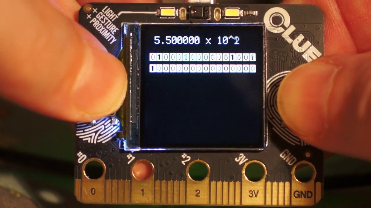
A prototype visualisation of IEEE 754 floating-point on the Adafruit CLUE written in CircuitPython and using accelerometer for data entry. The sign, exponent and mantissa have different colour backgrounds but they are not easy to distinguish in this video. They might benefit f...
lone axle
I've been fascinated in that concept since I learned of it.
raven canopy
x controls word position in [list/tuple]. y just scrolls val = +/- val; ord(val)?
little tedious for the middle letters in an alphabet though. 😄
lone axle
@idle owl Thank you 😄 I will check on the image load thing I mentioned tonight and make a note on that PR if it turns out there is still a change needed in imageload for the pew pew m4 support.
idle owl
@drowsy fox Welcome! Are you listening in today? (lurking?)
 drowsy fox
I just joined now
gilded cradle
I haven't checked the mono oleds or epaper displays yet @idle owl. I think there's also some other displayio related libs that need to be added too.
lone axle
@simple pulsar neat, thank you for sharing that. I hadn't considered accelerometer before, there are some neat interactions that could be built from that for sure.
idle owl
@gilded cradle Yah I planned to ping you about it.
@drowsy fox I know, would you like to give a status update, or are you simply listening in?
onyx hinge
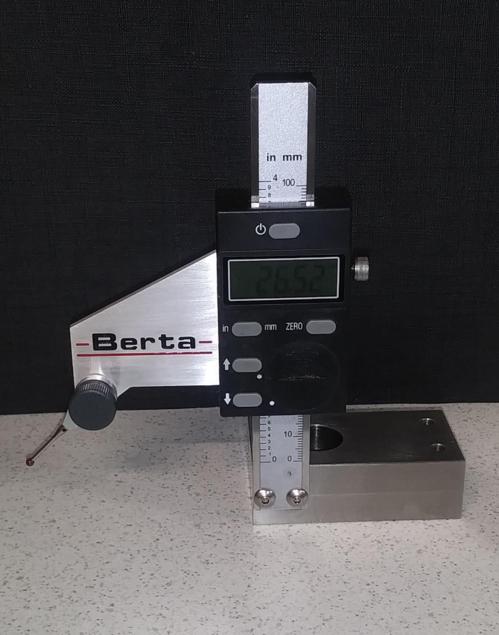
@drowsy fox happy to have you listen in. I dabble in machining so would enjoy the picture here or in #general-chat
drowsy fox
 simple pulsar
@lone axle I cannot remember what state (might be messy code) I left it in but the code (for a later version) is on https://github.com/kevinjwalters/circuitpython-examples/blob/master/clue/data-rep-calc.py

GitHub
Simple CircuitPython examples for Gemma M0 and similar boards - kevinjwalters/circuitpython-examples
onyx hinge

GitHub
Contribute to theacodes/Winterbloom-Hostess-FeatherWing development by creating an account on GitHub.

Twitch
▪️Software Engineer▪️Pythonista 💜🐍▪️Speaker▪️@frontendmasters author ▪️@recursecenter alum▪️Advocacy at microsoft ▪️she/her
(it's scott running the meeting, not me)
I think two things: First, we've been tackling this problem already when I take updates from ulab and discover that something in the C code didn't build -- I make PRs, they get merged in ulab, and then after that I can actually update ulab in CircuitPython.
Second, we will want to add documentation building to the CI of micropython-ulab. It won't guarantee that there are no extra problems that will occur when we build it in CircuitPython instead, but it will let us see it in the CI
lapis hemlock

Adafruit Learning System
Use numpy-like commands to process data quickly
onyx hinge
(v923z added the second ulab implementation if I recall correctly. his was faster)
Benchmarks could be valuable in order to let us notice whether there has been a regression
simple pulsar
@onyx hinge Speed, memory and check the actual results for correctness / FP accuracy (& bogosities).
onyx hinge
I'm happy with any chosen outcome that is not clearly awful and I just want to implement it.
drowsy fox
Sorry I had to disconnect and take this call
onyx hinge
https://circuitpython.readthedocs.io/projects/busdevice/en/latest/api.html is already called I2CDevice
simple pulsar
Is I2C multi-master?
tulip sleet
i have never heard of multiple
onyx hinge
There are I2C environments where multiple masters are driving the bus. More details on how this works are shown on this page.
tulip sleet
multiple mains is still fine
lapis hemlock
There are I2C environments where multiple masters are driving the bus. More details on how this works are shown on this page.
stuck elbow
if we are changing the API, can we also change the "clock" parameter to SPI to "SCK", so that it matches MISO and MOSI?
onyx hinge
The PR we're talking about is https://github.com/adafruit/circuitpython/pull/3034
GitHub
I think this corrects most of the M/S terminology that does not depend on upstream libs such as asf4, softdevice, etc., renaming things.
Note that there is an incompatible new name for the i2csecon...
simple pulsar
So master is a role
stuck elbow
github is down for me at the moment :(
stuck elbow
@simple pulsar master device and slave device
how about "manager" for master? it does manage the bus?
oh, sorry
raven canopy
hehe. i was just thinking that Dan.
idle owl
Learn guides have already been updated...
SDA - I2C data pin OR the Sensor Data In / Microcontroller Out Sensor In pin, for data sent from your processor to the LIS3MDL or LSM6DSOX.
SDO - this is the Sensor Data Out / Microcontroller In Sensor Out pin, for data sent from the LIS3MDL or LSM6DSOX to your processor. ```Gizmo has MOSI on top
feather M0 bluefruit has MOSI and MISO - feather M4 does not
onyx hinge
Thanks Scott
 tulip sleet
👍
onyx hinge
as a reminder to everyone who listened all the way to the end..
tulip sleet
what is the opposite of miso soup? ingredients with sauce?
onyx hinge
we cook ingredients with sauce all the time. It's my spouse's favorite
stuck elbow
mosi soup
ionic elk
a single, dried out piece of seaweed
stuck elbow
mochi
tulip sleet
it's a separate menu column
stuck elbow
miso and mochi
onyx hinge
wait miso mochi might be amazing
ionic elk
🤢
onyx hinge

We are making Gohei-mochi, a simple snack using rice and walnut miso paste. The sweet walnut miso paste is delicious roasted. The sansho pepper gives it a little bit of kick! [recipe]
simple pulsar
bye
gilded cradle
Thanks
prime flower
👋
onyx hinge
oh wow I am just swooning (in a good way) at the idea of roasted sweet walnut miso
stuck elbow
it's decided, we are renaming spi to gohei then
simple pulsar
Cooking with dog does not mean what I initially thought it meant
onyx hinge
@slender iron thank you for running that discussion and letting everyone have their say. I will be pleased to roll ahead with your recommendations hopefully this week
@simple pulsar no, I thought the same thing when a friend told me about the video series years ago but that's just me being an awful racist I guess
manic glacierBOT
Ok, so we just discussed this in the weekly meeting. The conclusion is:
- I2CSlave -> I2CPeripheral
- "Master *, Slave *" -> "Main *, Selected (peripheral) *" Guides already use some other terms so we should focus on the MOSI and MISO acronyms.
slender iron
☝️
simple pulsar
@slender iron your mic is still live
Is github borked in the US too? I'm wondering if it's regional
stuck elbow
borked in switzerland
tulip sleet
Welcome to GitHub's home for real-time and historical data on system performance.
simple pulsar
I got 140.82.118.3 as an A record earlier briefly. That's in Holland apparently. Turns out they got their own AS too.
lone axle
Seems to be working for me (in US) but I am only browsing a few pages not trying to use any repos specifically atm.
simple pulsar
No DNS (= no service) most of the time here in London, UK. Will be interesting if they've got a global LB DNS solution with the typical health checks and no ultimate backup
idle wharf
@idle wharf Good to hear the usb breakboard is working. I was just about to suggest adding the s3 link and I saw you already did.
@silver tapir -- Yeah, I was going to cut-up another cable, but when I could get a USB-C breakout for $2.50 I decided to wait and do that. Once that was in place, the WROVER showed up as a drive immediately. The breakout will be useful for a lot of other things as well.
I'll update my Gist and post back later for getting started running on CP on the WROVER.
tulip sleet
@onyx hinge I resetarted the misc fixes PR run. It's restarting slowly but has already run "test"
@onyx hinge The single build that failed the first time passed the second time. I will cancel the rest of the re-run and merge.
onyx hinge
Thank you @tulip sleet
manic glacierBOT

Created definitions for the TTGO XY-ESP32-S-WOOR board based on the Saola 1 WROOM definitions. The TTGO board is also based on an ESP32-S2-WROOM module.
Trying out the Adafruit 2.0" 320x240 ST7789 based display I get a incredibly slow refresh rate considering the speed of this MCU. A full refresh takes about 2 seconds.
The display works over SPI and I tried setting higher SPI clock rates but that does not seem to have any effect.
The same code works about 20x as fast on a Feather M4. I haven't done any measurements but just from looking at it I get an instant screen update on the M4 while the Teensy needs about 1-2 seconds to draw.
You can...
So I hooked up my scope and I get 17.5MHz no matter what I feed into spi.configure()
This is the modified example with setting SPI clock.
import board
import terminalio
import displayio
from adafruit_display_text import label
from adafruit_st7789 import ST7789

# Release any resources currently in use for the displays
displayio.release_displays()

spi = board.SPI()
tft_cs = board.D5
tft_dc = board.D6

while not spi.try_lock():
    spi.configure(baudrate=32000000)
p...Interestingly if I put a print() in the while not spi.try_lock(): loop I get nothing printed. The display still draws something to the screen though.
Not really sure how that can work but maybe the root cause for not being able to set the clock rate.
manic glacierBOT
Looks good to me! Thank you!
Thanks for the quick follow ups @DavePutz !
Do we need a new exception object or can we just raise the MP_STATE_VM(mp_pending_exception) value?
@dhalbert The way you fixed it though ensures that power is 3.3v or above right? Maybe all of our bootloaders should ensure that.
64k of ram is used for the instruction tightly coupled memory (TCM) and the data TCM. This is done so that code can execute as fast as possible.
I'm not sure why the starting heap is so small. It may be accounting for the stack even though the stack should be placed in the TCM.
We don't have cycles to look into the iMX RT bugs at the moment so let me know if you need help looking further into it.
The try_lock grabs the lock immediately and skips the loop body. The configured rate of the SPI is ignored by the display code as well. Instead, give the baudrate to FourWire so it knows and can call configure every time it transmits to the display.
Thank you for the PR! One request about the USB VID and PID.
Would you like CircuitPython to control these directly instead? Here is how to do it: https://github.com/adafruit/circuitpython/blob/main/ports/atmel-samd/boards/metro_m0_express/mpconfigboard.h#L5-L7
No, the bootloader just ensures that the power is above the brownout detection voltage, which is 2.7V. 2.8V is the maximum detection voltage on nRF52. 3.3V is probably too high, since it limits the battery life, and also the voltage after regulation may be lower.
Even ensuring a high voltage doesn't necessarily help. For instance, once the program starts up, it may start up devices that draw significant current (such as a wifi adapter or LEDs), and those could cause the voltage to sag. So ...
Thank you! Don't forget to add it to circuitpython.org as well.
Whose responsibility is it to make sure the external SPI flash voltage is high enough? The ability of the CPU to run may not match the voltage requirements of external chips on the board.
I also tried this but unfortunately makes no difference as well.
lone axle
Is there a way in code to check if the device it's running on supports longints?
Or a way to catch an overflow error caused when trying to use one on a device that doesn't support it. I have this code:
if height > 0x7FFFFFFF:
    height = height - 4294967296
that causes this error OverflowError: long int not supported in this build
and if I change it like this I still get the same error it doesn't get caught:
try:
    if height > 0x7FFFFFFF:
        height = height - 4294967296
except Exception as e:
    print(e)
I tried except OverflowError as e: as well but doesn't seem to make a difference.
crimson ferry
something something bitness? https://docs.micropython.org/en/latest/library/sys.html
M0:
1073741823```M4:```>>> sys.maxsize
2147483647```Just noticed that sys isn't in the readthedocs Core Modules
lone axle
That seems like it should be able to work for my needs but it seems the issue is deeper. This device has maxsize 1073741823 like the M0, but I'm still getting the overflow
manic glacierBOT
@hierophect please post a video, it isnt clear to me what you're referring to
lone axle
reducing it down to the simplest case:
if False:
    if 9 > 0x7FFFFFFF:
        print("something")
even though we have if False: and therefore won't ever go inside this the next line still makes an OverflowError
manic glacierBOT
We want to do this in the long term but will likely wait to hear more from GitHub until we do all of the library repos. CircuitPython core is already switched over.
@brandonvfx Can you test the latest version? It should be more accurate thanks to @DavePutz

I suppose the minimal voltage could be configured in the bootloader's configuration, together with the display stuff.
@kattni did you have @ptorrone update it yet?
crimson ferry
@lone axle "Integers in CircuitPython" https://learn.adafruit.com/adafruit-feather-m0-express-designed-for-circuit-python-circuitpython/circuitpython-expectations
manic glacierBOT
lone axle
I'm curious how to successfully work around it though. So that on devices that do support it, the longint can get used but on devices that don't we will be able to get past this error
maybe the lines of code trying this can be refactored into a different file and then imported conditionally
@crimson ferry thank you for pointing me in the right direction! I was able to work around it like this:
        if sys.maxsize > 1073741823:
            from negative_height_check import negative_height_check
            height = negative_height_check(height)
well
perhaps spoke too soon. It's not breaking the device without longint anymore but needs some help on ones that do. I will get there though.
 simple pulsar
@lone axle On 5.3.0 on a CLUE I see a bigger number for sys.maxsize, your code looks like it should be ok? ```>>> import sys
sys.maxsize
2147483647
devil was in the details. import needed to be slightly different
from .negative_height_check import negative_height_check
leading dot on it
simple pulsar
Ah
lone axle
It is working now though 😄 on devices with longint it's getting used correctly (as far as I can tell). and on devices without now we get a nicer NotImplementedError.
and on non-longint builds they can now work without crashing on BMPs with positive heights
Oh wow
manic glacierBOT
@tannewt I think that ball is in my court. I'll send an email asap
I put in the request just now
manic glacierBOT
Extraneous #includes have been removed. As far as the exception object, we have to clear the
MP_STATE_VM(mp_pending_exception) or subsequent sleep() calls return immediately (i.e. the original issue #2865). nlr_raise() cannot be called before clearing the exception, as that will never hit the clear. So, yes, we need a new KeyboardInterrupt exception object.
manic glacierBOT
The SPI flash chips generally have a minimum operating voltage of 2.7V.
The nRF52840 has a forced reset when VDD is below 1.7V. It has a comparator that can generate an interrupt when VDD is below a set value. The maximum such value is 2.8V.
The SAMD51 can set the BOD33 brownout level up to about 3V. The SAMD21 can be even a bit higher.
The main issue, as I've mentioned, is that the battery voltage can be satisfactory at a light load to pass the voltage requirements, either in the bo...
manic glacierBOT

Right now, CircuitPython can't remount the MSC storage when it has been mounted by the computer. We can add a feature to eject the storage from the device side. The feature is already supported by DAPLink.

I tested main on a Saola and my board, and it looks like both issues have been resolved. Thanks! 😃
solar whale
@onyx hinge FYI -- my AHT20 won't get here until tomorrow -- UPS delay 😦
onyx hinge
oh well, it's no hurry
manic glacierBOT
This looks good to me! Thank you!
@tannewt You told me once to ping you if PRs are not looked at for a few days...so here's your ping
crude blaze
does anyone know what main clock frequency the SAMD51 port is using and where I would change it?
I dug into the ASF4 clock settings part a bit but that is quite a rabbit hole.
In the Arduino core there are defines to overclock the chip, I want the same for CPY essentially :)
Is there maybe even a user friendly per board setting for this that I'm missing?
tulip sleet
it's 120MHz
crude blaze
ok thanks, do you know where I would set this off hand?
If I understand the Arduino startup code correctly it is set as part of GCLK0
Then there is the main clock divider but that doesn't seem to be the end of the story, in the Arduino core its just hard coded to 1 same with cpy
the only thing modified by that overclock define affects GCLK
tulip sleet
there are a number of places where that number is assumed. If you changed it in the clock setting, other timing measurements would start to be off, like SPI frequency, and possibly time-keeping too
ports/atmel-samd/asf4/samd51/config/peripheral_clk_config.h:584:#define CONF_CPU_FREQUENCY 120000000
ports/atmel-samd/mphalport.c:62:#define DELAY_LOOP_ITERATIONS_PER_US ( (30U*120000000U) / common_hal_mcu_processor_ge
t_frequency())
ports/atmel-samd/asf4_conf/samd51/peripheral_clk_config.h:584:#define CONF_CPU_FREQUENCY 120000000
some things like neopixel operation might stop working
crude blaze
oh ok I see, are there more assumptions made based on the main clock in CPY vs. the Arduino port?
tulip sleet
in other words you'd need to clean up those assumptions
it would take some study about whether there are other things that might be affected. How much do you want to overclock it, and what do you want to be faster?
if there is some aspect of your code that's running too slow, it might be worth spending more time trying to optimize the python code rather than spend time on overclocking
the asf4 settings are in some cases ignored or overriden
crude blaze
I have an application in mind where I would need some more involved animated graphics and I wanted to try if I can improve on the performance with an increased clock
SPI clock would be the next thing I would want to look at as I think the display supports a higher clock rate than is currently allowed by CPY (or the library I'm still a bit confused where these limits are defined
tulip sleet
that ports/atmel-samd/mphalport.c number should use the #define. We try to allow the max SPI possible, and have tried to set the display clocks as high as possible in the various drivers
crude blaze
yea I'm guessing thats what the asf4_config folder is for to override the defaults from the as4 repo?
tulip sleet
yes, but we stopped using most or all of the asf4 clock-setting code, if I remember right, and have our own
crude blaze
oh ok
tulip sleet
some of the clock code is in https://github.com/adafruit/samd-peripherals/tree/master/samd
crude blaze
thanks!
tulip sleet
you'll need to trace that back and see what divisors it's called with, etc.
crude blaze
ok when SPI is already maxed out as much as possible, another question I had, offer parallel screens a faster transfer rate? I haven't looked into that yet but I've seen you use a parallel screen for the massive titano pyportal
tulip sleet
I believe so, but @slender iron or @gilded cradle would have more to say about that. But if you are using displayio, then you'd want to see if how you're using it could be improved (or the underlying C code could be improved).
crude blaze
yea thats fair, currently I'm using https://github.com/adafruit/Adafruit_CircuitPython_ST7789
no idea how optimized that driver is, still at a very early stage with my research 🙂
GitHub
CircuitPython DisplayIO Driver for ST7789 Color TFT Controller - adafruit/Adafruit_CircuitPython_ST7789
manic glacierBOT
A MP_STATE_VM(mp_kbd_exception) object is created once, here:
https://github.com/adafruit/circuitpython/blob/65512cef1c278258f525422fe57271ffac6f51b0/py/runtime.c#L81-L86
So you should just be able to reuse it, I think:
nlr_raise(&MP_STATE_VM(mp_kbd_exception));
@tulip sleet do you think we need to add anything named after SAME54 in libusb? Right now the SAME54 build will use CFG_TUSB_MCU=OPT_MCU_SAMD51
tulip sleet
i think it's up to @gentle bronze whether he wants to add tinyusb/src/portable/microchip/same54, or generalize the samd51 tree. I'm guessing there's no actual difference.
onyx hinge
no, it seemed to work just fine
tulip sleet
just finished a comment in samd-peripherals too. i know it's a lot of work to generalize all the names; we should have done that initially instead of assuming samd51 only forever
onyx hinge
Yeah I wasn't tracking which repo you commented in, I responded as if it was about asf4
sorry about that, I should read twice before responding
tulip sleet
you could open an issue on tinyusb to ask if Thach wants to generalize the name; it may not be worth it.
it would be a long-term to-do for him
onyx hinge
I don't need to create work where it's not needed
tulip sleet
i agree, thought a comment somewhere that same54 == samd51 for tinyusb might be good in the long run
onyx hinge
OK, I filed a "question" issue over there
gilded cradle
@crude blaze, yes. Using parallel data should be faster. I believe that's how the PyPortals are connected just for that reason.
manic glacierBOT
Sorry about that, was under the impression that this would be on the level of the WROOM module. Are VID/PID normally supplied by the board manufacturer?
crude blaze
@crude blaze, yes. Using parallel data should be faster. I believe that's how the PyPortals are connected just for that reason.
@gilded cradle good to know thanks!
onyx hinge
I suspect there are also inefficiencies in the "rendering" code, because it was written to be simple and flexible rather than as fast as possible. We'd love if someone took a look at it with an eye to optimization, though any changes which have an impact on code size might have to be optional so that our most FLASH-constrained devices continue working.
(it's also possible that code is "fast enough" that it's the data transfer that is the bottleneck; for instance, SPI bus speed on nRF52 is a major contributor to screen update time, at least when 'simple stuff' like a bitmap is displayed)
 broken hedge
CircuitPython Bluetooth: When using the .complete_name property of a ProvideServicesAdvertisement, I'm not seeing it in the app. I believe this had worked, before. I'm trying:
uart_server = UARTService()
advertisement = ProvideServicesAdvertisement(uart_server)
advertisement.complete_name = "BabyYoda"
but when I run the code + open the BlueFruit app, the LOCALNAME is the same as the name listed above Uart capable. I thought I had used this technique perviously & it was working. Any thoughts on what I'm doing wrong?
manic glacierBOT
Yes, testing shows that we can reuse that object. I have changed the code accordingly.
tulip sleet
@broken hedge I can try some things and get back to you, but the easiest way to set the name is to set the .name of the BLERadio()` instance, instead of trying to add it to the advertisement. It may not fit and instead will be added to the scan response.
Note that various clients (iOS and Android) often cache the name based on what it was previously, so you may need to forget the device to see the new name.
broken hedge
Trying to make it easier to recognize this guy:
Thanks @tulip sleet. I just tried
ble = BLERadio()
ble.name = "BabyYoda"
but I still don't see a change. Service is UART Service, LocalName is the same as the name shown before clicking on it. As for forgetting the device - sorry if I'm dense + not noticing how to forget, but on iOS I don't see "forget" as an option inside the Bluefruit app. The Bluefruit isn't showing as a device connected to the iOS device's bluetooth. If I force-close the app, then re-start, I still see the same results - no "BabyYoda".
tulip sleet
you have to go to Settings -> Bluetooth and forget the device, or if you don't see it, turn bluetooth off and on there.
if you try setting .complete_name, the ble.name will still be set in the scan response, so it's better to set ble.name, ans you did
the bluetooth implementations aggressively cache a lot of information, and don't expect it to change (since most devices don't change their names)
very cute project
slender iron
@broken hedge there is a second way with a gatt service that the name is fetched. once the devices are connected, the name for the service will be used and cached I believe
broken hedge
@tulip sleet hmm very strange. I've tried restarting the device, also completely turning off bluetooth then restarting. Results are the same. I've also tried printing the ble.name and advertisement.complete_name right after I ble.start_advertising(advertisement) and both show up properly as the "BabyYoda" string.
manic glacierBOT
tulip sleet
is CIRCUITPYnnnn in the device list in Bluetooth settings?
touch the circle-i in the list and Forget this Device
broken hedge
@tulip sleet & @slender iron I'm actually less concerned with this showing up properly in the app. I do want a recognizable, non-changing name that I can refer to when writing code on an Internet-connected Pi. Am planning on the "Pi" to receive inbound MQTT from anyone who wants to activate Yoda via an app I'll distribute, then have that Pi recognize the CPB inside Baby Yoda. Figured if I could name the CPB and somehow look this up in my Pi code, this would make it clear I was connecting to the right CPB (since I've got several in the house). Thanks!
manic glacierBOT
@k0d Yup! Thank you! I thought you were going to follow up with an update.
We're more focused on the ESP32-S2 at the moment since they've become available.
I'm happy to help you dive into CircuitPython if you like. :-)
It isn't possible to eject from the device side as far as I know. We could simply make the drive disappear but that is very risky since it is common for the host OS to cache filesystem changes.
What are you trying to achieve?
Yes, it's best practice for them to vary per board so that hosts can identify the board based on it. At Adafruit we go even further and have three per board: one for the bootloader, one for arduino and one for circuitpython. Some OSes cache the USB descriptor and/or driver based on the PID so fewer issues occur when separating the three modes.
I figured that focus shifted there :)
An intro would be nice actually. I'll ping you on Discord.
 lone sandalBOT
 manic glacierBOT
Please rerun make translate to get the latest file move info in the file. Thanks for sticking this out. I think it's close.
I feel like the use of device is a little confusing here and "main" doesn't really help. What do you think about saying "host" instead? My preference would be to use "main" only in MOSI/MISO context. Everything else can be host/peripheral and "selected peripheral".
#endif // MICROPY_INCLUDED_ATMEL_SAMD_COMMON_HAL_BUSIO_I2C_PERIPHERAL_H
#ifndef MICROPY_INCLUDED_ATMEL_SAMD_COMMON_HAL_BUSIO_I2C_PERIPHERAL_H
#define MICROPY_INCLUDED_ATMEL_SAMD_COMMON_HAL_BUSIO_I2C_PERIPHERAL_H
Thanks for the review! I especially appreciate you finding the things I just overlooked in the repeated renamings.
@tannewt Please take a look again, and at #3037 to see that the computed values and the hard-coded values agreed in all cases before I removed the hard-coded values and replaced them with the computed values.
simple pulsar
@broken hedge I am using complete_name in a BLE application successfully on 5.3.0. In my case I'm not setting it explicitly but picking it up from the ble.name via the scan response packets. I've just had a glance at my code and it looks like it just works for me. I know that doesn't help but it does add a bit of weight to the feature being ok. I also see the name pop-up if i use a BLE scanner on Android.
manic glacierBOT
It might still be the case that someone wants to omit MSC OR CDC, so either we should let them set USB_DEVICES still and override this, or perhaps better, we need something like CIRCUITPY_USB_MSC and CIRCUITPY_USB_CDC, which default to 1. I don't think we need CIRCUITPY_MSC_MIDI or _HID, because there's no use to including the code without exposing it for those bits of functionality.
For instance, I have CircuitPython-based Trinket M0 volume control that has a special build that ...
Haha...no...that's a good enough fix for now. I'll do some deep dive into it at some point...maybe bring it up at 'in the weeds' on a Monday.
manic glacierBOT
How about I change +USB_DEVICES := "$(USB_DEVICES_COMPUTED)" to +USB_DEVICES ?= "$(USB_DEVICES_COMPUTED)" so that it becomes a conditional assignment, and any value from a mpconfigboard.mk would override?
manic glacierBOT
To add a new file to the storage without user .
It is possible. DAPLink supports drog-n-drop programming which is similar to uf2 programming. When something gets wrong, DAPLink will create a text file with a error message.
The host OS will drop any cache when a device is ejected.
manic glacierBOT
To add a new file to the storage without user .
I'm not sure what you mean by this. If you want to write to the filesystem, you can do it before USB is initialized when CircuitPython starts up.
It is possible. DAPLink supports drog-n-drop programming which is similar to uf2 programming. When something gets wrong, DAPLink will create a text file with a error message.
I don't think DAPLink actually has a FAT filesystem. (UF2's filesystem is fake.)
With CircuitPython, the FAT fil...
manic glacierBOT
Following the guide - https://learn.adafruit.com/circuitpython-essentials/circuitpython-storage, the device is able to write a new file to storage, but we need to reboot the device to see the file. It's a solution anyway.
I agree the cache issue that two writers may conflict. When the storage is read-only to the host, ejecting from device side cloud work.
manic glacierBOT
I removed start and stop functions.
I added a timestamp when positioning data was received.
Update does not return data. This function updates all positioning data in the GNSS object to the latest.
I can add that the update function returns bool. When it returns True means that the data has been updated, if False means that the data has not been updated. What do you think about it?
silver tapir
I'm just catching up to the recording of the weekly meeting. I was being hugged and didn't even knew it :). Thanks for the hug reports.
Also, my two cents on the M/S terminology for pull request 3034. I'll stay away from the technical discussion about which is more appropriate, I'll just give my opinion about which of the words I've heard translate well to spanish.
So on the perspective of which works keep the M/S initial and how they translate.
Ah, the bot cut me off.
manic glacierBOT

This is how some of the words that have been discussed translate to spanish.
main -> principal (we loose the M initial)
manager -> administrador (same)
host and device -> dispositivo (host and device and normally interchangeable)
peripheral -> periférico (ok)
selected -> seleccionado (ok)
 fluid patio
How do I use a library if there doesn't seem to be a .mpy file? https://github.com/adafruit/Adafruit_CircuitPython_Debouncer
GitHub
CircuitPython pin or arbitrary predicate debouncer - adafruit/Adafruit_CircuitPython_Debouncer
lone axle
@fluid patio you can get the mpy file from inside of the library bundle from here: https://circuitpython.org/libraries
The easiest way to program microcontrollers
click the 5.x mpy bundle button:
fluid patio
thank you!
lone axle
You're welcome. You can also make the mpy file yourself with a utility called mpy-cross that is in the main circuitpython repo.
but if you're looking for one of the libraries the easiest way is just to download the pre-built one.
fluid patio
Thanks. and Thanks to you and @prime flower for suggesting the debouncing. It works like a prince! It was causing a lot of my issues
Also sorry I posted here @lone axle I meant to post in help-with-circuitpython
lone axle
No worries. I didn't notice either 😄
Debouncer is really neat. I don't think I saw the prior conversation about what you are using it on. But it's nifty in that it can handle different types of things, not just "regular" buttons.
It can handle cap touch, or any other type of input really because you can pass in a function instead of a pin object.
onyx hinge
Thirding that debouncer is nice functionality to have
prime flower
@fluid patio No problem! I'm glad it's working for you.
onyx hinge
@ionic elk can you walk me through how to add information about sdio pins to stm? I see there are some scripts, are those used to generate the files in peripherals/stm*, which are subsequently committed?
ionic elk
let me remind myself real quick
onyx hinge
Thanks, I appreciate it
manic glacierBOT
If giving USB_DEVICES in mpconfigboard.mk would override it, would that also override the check? That's why I suggested adding CIRCUITPY_USB_MIDI and CIRCUITPY_USB_HID as toggles, so that the user never has to see USB_DEVICES.
btw, I don't understand the reason for using := here instead of =. I know it makes an immediate instead of a deferred assignment, but would it not work with regular =?
Another check we could add (this is getting complicated) is counting endpoints f...
Yes, specifying USB_DEVICES manually would skip the check.
The := is necessary when building USB_DEVICES_CALCULATED up in parts, because with the usual = syntax, this is a self-referential variable: USB_DEVICES_COMPUTED := $(USB_DEVICES_COMPUTED),AUDIO. However, in the current version that only applies to USB_DEVICES_COMPUTED and not to USB_DEVICES, which is good, because there's no ?:=.
Technically once you turn off MSC or CDC you don't have a CircuitPython compliant board a...
onyx hinge
I guess not all of the needed .csv files are commited ? I see only two "examples"
ionic elk
@onyx hinge ok, I've caught myself up again. The files in tools/ are designed to extract the peripheral information from a .csv file that's extracted out of an STM32 datasheet, using the "alternate function mapping" table. STM32 peripherals like SDIO or I2C are all associated with a pin and an altfn number, which lets you select which peripheral the pin is connected to (one pin could be GPIO, I2C or SPI with different altfn numbers). You can get this CSV with a pdf-table-to-csv app or by using the ones that Micropython already made (they're included for every SoC they support).
The python script reads through the csv table, and sets up pin objects that sort by pin name (SDA, SDL) and correctly store the peripheral, the peripheral altfn number, and other custom stuff like timer channel etc through hard-coded special cases.
If you want to make one for SDIO, you'd need to add the SDIO D1, D2 etc to the list of terms it searches and sorts for, but I don't actually recommend it - this system is really intended for pins with "overlapping" functionality, and SDIO pins tend to get used just once. I'd just look at the pin structures and copy paste it yourself. You'd need to change everything for F7 and H7 chips anyway since they use the SDMMC acronym instead of SDIO.
@onyx hinge I haven't bothered to commit the .csv files, no. Most of them are available in Micropython. I guess we could store them somewhere
onyx hinge
I feel that when there are "generated files" that the build process should make them, and that means all the inputs need to be committed (while the outputs need not be committed). But right this moment I need to NOT complicate my current task -- which is to get the SDIO pins available / checkable for stm32f405 -- by taking that on
ionic elk
That would be a pretty significant waste in this case. There's no reason to ever regenerate the files outside their time of creation.
They also get tweaked sometimes so my scripts don't even do things like declare the index arrays or license info, they just spit out some boilerplate that you build the rest of the file around.
onyx hinge
Yeah getting to 100% generated can take an extra 90% of effort
in the case of stm32f405 there is just one set of SDIO pins, should I integrate it in the peripherals/ files or paste it directly into the sdio implementation file? e.g., ```const mcu_periph_obj_t mcu_sdio_sdio_cmd_list[1] = {
PERIPH(_, 12, &pin_PD02),
};
"_" means there's no peripheral number I guess? Is that gonna build?
seems like no
ionic elk
I think there's only set of SDIO across most boards
onyx hinge
okay, the F7 has multiple instances too: e.g., SDMMC1 and SDMMC2 though
ionic elk
Does SDMMC use the same HAL interface?
onyx hinge
I do not know. I've only done STM32F405 so far.
this one would not be surprised if .. not
ionic elk
I would put in a periph value of 0 or 1, not a character
0 is an "unused" value, so it'd be distinguished from other peripherals, but I don't see a problem with just putting in 1 and not using it.
onyx hinge
Yeah it's getting "_" because the csv says SDIO_CMD
ionic elk
Oh, I see. Yeah you'd need to code a special case. That's why I said you might want to avoid doing it.
Like I said the system is really built for these peripherals that have big tables of interchangeable instances that need to be searched. For a single peripheral it doesn't make a lot of sense. The DAC module, for instance, just has it hardcoded because it's the same two pins across every F4 chip
If you can confirm that's the same for the SDIO, I'd just do it the same way.
(by "hardcoded" I mean that there's no peripheral instance and all pin selection/checking/altfunction is handled by the common-hal module itself.)
onyx hinge
    PERIPH(2, 10, &pin_PB15),
    PERIPH(1, 12, &pin_PC09),
    PERIPH(2, 11, &pin_PG10),
};
``` with the stm32f767 it gets more complicated.Are you surprised that the AF # is not the same ?
no, something's funky, the SDMMC items are all in column "M" when I import the csv in libreoffice
ionic elk
I mean always start by looking at the actual table and get a handle for it
I'm not surprised that the altfunction changes by instance for a peripheral that has different indexes, that happens a lot on STM32. They often have an altfunction reserved for a specific periph number
you can see it on the pdf table headings
onyx hinge
OK yeah the PDF has SDMMC2 on AF10 and AF11, and SDMMC1 on AF12
this'll be fun, there are up to 10 pins involved
ionic elk
sounds about right. So yeah these tables are a good idea for that case, because you need to search. Are there multiple instances of individual SDMMC pins? like SSDMMC2 D1 is on several different pins?
This is when it's good to have the python script do it for you yea
onyx hinge
yep on STM32F767 see above
ionic elk
Oh yeah I see.
Yeah I don't envy the nested loop you'll need either it'll be 6 layers deep
onyx hinge
I don't see any case where the pin can be this instance or that instance
so that's something at least
ionic elk
That could save you a check, but you might want to leave it in there anyway, ST loves to sneak stuff like that in there
I'd check out the SPI implementation of the loop for reference.
manic glacierBOT
Can we leave other improvements to the future in order to get this improvement in place?
Yes, that's fine with me.
onyx hinge
Do you mind running through that again, I know that I had an over-simplified view of things before and it falsely let me believe the loops could be simplified
you do a for-each-pin, for each pin, for each pin, see whether you can satisfy all the requirements, because that's the only way you see to work within the very complicated pin mapping that stms have
nested
manic glacierBOT
This is a good error checker for now. Thank you ! It can be made more flexible/strict later.
The single Actions failure is not interesting: it's the usual sort of github hiccup.
onyx hinge
I think I wanted to de-nest everything, which I get now that won't work since it won't check all possible combinations where a pin is part of (say) SPI1 and SPI4 and only the latter combination will work; you can't stop at the first function you find
but what if you have one outer loop on function number and within that you check whether all the pins fit with that function number. Will that let the search for pins be de-nested?
for(all peripheral indices) { look for sck; maybe look for mosi; maybe look for miso }
ionic elk
I don't know if I understand - the pin objects that get passed into a function do not contain any information about the peripherals they support. You have to search the peripherals for matches
onyx hinge
sure, I'm just trying to get the structure to be flat, not nested
ionic elk
that was the tradeoff - STM32 pins had too many peripherals and options to feasibly store per pin
onyx hinge
the structure of the "searching" code
ionic elk
I don't really get how you could do flat searching. You need to check every combination of pins. For most peripherals you can even have cases where one pin supports multiple different functions of the same peripheral number, or has multiple peripherals on it, or any combination of things
But I'm probably not properly understanding what you're suggesting. Could you outline it really specifically?
onyx hinge
Let me try
imagine for the sake of argument that the Python API was different, so you had busio.SPI(sck, miso, mosi, periph_index)
can't you do a flat search, to find out whether sck works with that periph_index; then (if not None) miso; then (if not None) mosi
because you committed to a periph_index first, it becomes simple to say "this will / will not work"
?
simple and flat, not nested
onyx hinge
I am really interested in settling the question for SDIO, but I am phrasing it as a conversation about SPI because that code exists concretely right now
the "search for sck" would be a loop over mcu_spi_sck_list checking for a match of pin and periph_index, etc
ionic elk
I think I see, so you'd bundle checking whether the peripheral index is correct alongside seeing whether there's a pin match. To avoid the periph index, you could search for a match for SCK, and then search for the other pin matches based on what it found for the first one.
The issue with that would be that many peripherals have multiple overlapping sets of viable pins for a single peripheral index
or multiple viable peripheral indexes for a single set of pins
onyx hinge
RIght but in the hypothetical the user has committed to the pins and to the periph_index
isn't it just a matter of checking whether it works or not?
ionic elk
I'm not understanding how what you are suggesting is different from what we have
onyx hinge
It flattens the structure of the code
which is managable with 3 like SPI has but not managable with 10 like SDIO has
(once you arrive at agreement with me about the case where the user specifies periph_idx, I say, well let's just loop over all the periph_idx. Now you've got an inner and an outer loop, but not a loop that is nested as deeply as the number of pins the peripheral has altogether)
ionic elk
I think it works for your specific case yes, it just won't work for other peripherals
Backing up a little, we don't have the user commit to a peripheral idx because that requires them to read the datasheet
onyx hinge
I agree, we don't do that and we won't start doing that
ionic elk
what you're suggesting is having 10 separate loops that each check whether the pin exists in the array and picks the first one it finds, right?
onyx hinge
thinking about "suppose you do commit to periph_index at the outset" (as well as all the pins) and seeing whether that can "miss" a working combination is a part of my thought process, not something I want to change CircuitPython to do
ionic elk
I think there's actually a way you could do it... if you selected the periph_index off the first pin, and then searched each following pin array for the first match that satisfies both the pin AND the periph index AND isn't reserved already, etc.
you'd only check whether the periph_index is free in that first loop, and for the case where you've got multiple overlapping ones (like I2C1/I2C4 on the H743) you'd move on to pick the second one
I think I'd have to mess with it a bit to see if there are edge cases. But that could actually be a nice cleanup if it works... I will think about it more.
onyx hinge
Yes, and if there's some pin that is mandatory (SPI I2C and SDIO are all like this) then you can search for that one as the outer loop instead of looping over all the instance numbers as I suggested
ionic elk
Right, it'd only be a little tricky when both are optional, like UART, but I'd figure it out
The existing system is trying to figure out whether the peripheral indexes match, but that's not really important - you should assume the first index you find is correct (unless it's reserved) and then search based on that...
onyx hinge
reserved_spi[] means that it's in use by some other busio.SPI object right?
ionic elk
right, it tags a specific peripheral index as being in use
for cases where you might have two completely parallel sets of pins for the same peripheral
onyx hinge
I really wish a BOOT0 button had fit on the stm32f405 feather
@ionic elk can I put uf2 bootloader on this thing yet?
ionic elk
GitHub
UF2 bootloader for STM32F4. Contribute to adafruit/uf2-stm32f development by creating an account on GitHub.
No jumper?
I tend to just use Jlink myself so I don't use DFU that often
onyx hinge
yeah that is probably wise
Tested with: ```import board
import busio
busio.SPI(board.SCK, board.MOSI, board.MISO).deinit()
busio.SPI(board.SCK, board.MOSI).deinit()
busio.SPI(board.SCK, None, board.MISO).deinit()
try:
busio.SPI(board.SCK).deinit()
print("Should fail")
except ValueError:
print("ValueError (expected)")
try:
busio.SPI(board.SCK, board.MISO, board.MOSI).deinit()
print("Should fail")
except ValueError:
print("ValueError (expected)")
try:
busio.SPI(board.SCK, board.MISO).deinit()
print("Should fail")
except ValueError:
print("ValueError (expected)")
try:
busio.SPI(board.MISO, board.SCK).deinit()
print("Should fail")
except ValueError:
print("ValueError (expected)")
perhaps more easily viewed as https://gist.github.com/dc71752f8e877e1af91563b5d0fa9c09 @ionic elk

Gist
GitHub Gist: instantly share code, notes, and snippets.
@ionic elk good news on a different subject, it looksl ike the HAL_SD_ APIs are fairly similar
hah they corrected a typo though from one to the other. ```- __IO uint8_t FileFormatGrouop; /*!< File format group */
- __IO uint8_t FileFormatGroup; /*!< File format group */
@idle owl isn't there a program to check "all" the SPI port combinations and print the ones that work?
idle owl
There's a not as nice version on the CircuitPython Essentials DotStar page where you give it a pin combo and it tells you yes or no.
onyx hinge
do you recall running into a problem where the script would hard fault something?
like a particular board
idle owl
I rewrote it to spit out pin combos.
Hmm... not that I'm aware of
If it's hard faulting doesn't that mean there's an issue with SPI or something?
I mean, it tries to create a SPI object on every pin combo.
That's about all it does.
onyx hinge
OK
idle owl
I don't entirely understand what causes hardfaults so I'm simply throwing out ideas
onyx hinge
there was a particular bug on STM I was thinking about, that this code probably triggered
idle owl
Ah hmm
onyx hinge
actually it DOES cause a problem though hmmm
not a hardfault, though
let me check from before my changes though
oh good (?) maybe it's just caused by my local changes, yay
idle owl
@onyx hinge Bonus I guess?
onyx hinge
I double my thanks to you
idle owl
You can have triple welcomes then.
 tropic mural
I am currently running micro python on my esp32. Is there any way to switch back to Arduino IDE. Help me!
onyx hinge
@tropic mural yes, though if simply starting the upload process in Arduino doesn't work I'm not sure what steps to take. Both micropython and arduino use esptool to load code onto the microcontroller.
tropic mural
Ok I will try it.
onyx hinge
In the Arduino window if the upload fails it probably shows some messages; searching for those messages or asking about them in #help-with-arduino would be worth a try!
Both ESP8266 and ESP32 have to be reset in a certain way in order to launch the serial bootloader.
On some development boards (including NodeMCU, WeMOS, HUZZAH Feather, Core Board, ESP32-WROVER-KIT), esptool.py can automatically trigger a reset into the serial bootloader - in which case you don't need to read this section.
For everyone else, three things must happen to enter the serial bootloader - a reset, required pins set correctly, and GPIO0 pulled low:
https://github.com/espressif/esptool these instructions about entering the bootloader may be important depending on the board you have

GitHub
ESP8266 and ESP32 serial bootloader utility. Contribute to espressif/esptool development by creating an account on GitHub.
It's lunchtime here, good luck!
tropic mural
Thank you for your support @onyx hinge
slender iron
(fyi I'm going heads down on SPI to hopefully have a demo for S&T. will do emails and reviews later today)
onyx hinge
good luck tannewt!
slender iron
🙂
manic glacierBOT


this looks like a power or voltage issue. make sure the panel power supply is 5V or less
this looks like a power or voltage issue. make sure the panel power supply is 5V or less
That was my first thought too, or a connection issue, but I've found in testing that the exact same setup works fine (jumpers, cable, featherwing, everything, only the feathers & connection positions swapped) on the Feather M4 express and only gives this bad performance on the F405. It's using the 5V, 4A power supply listed on Adafruit.
manic glacierBOT
I believe you should also disable CIRCUITPY_USB_(MIDI,HID) for all of the boards that disabled it in the descriptor. That will free up more space.
Translations update from Weblate for CircuitPython/main.
solar whale
@onyx hinge just go t my ATH20 -- works fine on my GrandCentral_M4 ```Press any key to enter the REPL. Use CTRL-D to reload.
Adafruit CircuitPython 5.4.0-beta.1 on 2020-06-09; Adafruit Grand Central M4 Express with samd51p20
import ahtx0_simpletest
Temperature: 24.0 C
Humidity: 57.6 %
Temperature: 24.0 C
Humidity: 57.6 %
[adafruit/circuitpython] Issue opened: #3065 Allow custom builds to disable CDC, MSC in a better way
In #3038 @dhalbert suggested that it would be beneficial to allow CDC and MSC to be disabled just like MIDI and HID can be now. He gives a rationale there.
So:
- Add CIRCUITPY_USB_CDC and CIRCUITPY_USB_MSC
- Check them at various sites as appropriate to disable code and/or built in modules
- Use them to compute the USB_DEVICES string, instead of always including CDC and MSC
- A Makefile trick to deal with not getting a leading comma will be necessary
- When done, remove the ab...
In #3038 @dhalbert noted it would be handy to check that the enabled USB devices fit within the MCU-specific number of USB descriptors:
Another check we could add (this is getting complicated) is counting endpoints for boards with limited endpoints, and warning you there are too many. It has to know CDC takes 2, and others take only one. It could count words/commas in USB_DEVICES.
As it stands, I think such builds succeed but crash when loaded on a board.
trim elm
@tidal kiln I've updated the guide. Lemme know what you think. https://learn.adafruit.com/adafruit-4-channel-adc-breakouts/python-circuitpython#single-mode-3065656-41
tidal kiln
@trim elm thanks. will do. for the issue - did you actually come up with a fix?
trim elm
@tidal kiln Loosely speaking, yes. I called p1.value and p2.value twice in a row, and added a print statement that prints when it's in continuous mode
I also may have moved another line or two around, lemme check
Yeah, that was it
tidal kiln
that sounds more like something you are doing in application code?
did you change anything with the library source code?
slender iron
what do folks thing of splitting parallelbus and einkdisplay out of displayio into separate modules in 6.x?
tidal kiln
for the bus one - it's a pretty display specific bus?
slender iron
ya, they are both display specific but we don't always implement them with displayio
parallel bus in particular
eink may be ok since it is in shared-modules
tidal kiln
would you do the same for FourWire?
slender iron
I don't think so since SPI is so core
tidal kiln
but either could be the first parameter for creating a Display
right now, they are both in dispalyio
tidal kiln
you'd end up having to look in two different locations depending on bus?
slender iron
you'd have to import different modules
tidal kiln
so maybe OK? but might be confusing that one "display bus" is in one location and another is in another location.
slender iron
ya, we could split out FourWire and make displayio displaycore
tidal kiln
but FourWire and ParallelBus would still be in two different locations?
slender iron
@ionic elk that's what major versions are for 🙂
anyone testing ESP32-S2 may want to try my latest branch. SPI TX works, I removed the delay and sped up the CPU
will show and tell it today
ionic elk
@slender iron quick request for your input on something: I'm putting together the timer allocator, and I'm thinking about trying to avoid the basic non-pin timers altogether because they have a different control API and register set. It'll be easiest to allocate timers if the program knows which ones are being used externally for PWM first, so how would you feel about a new warning that asks users to move their PWM object declarations before declaring PulseIO, RGBMatrix, or RotaryIO objects?
So basically if you try to use a pin for PWM via a timer that already got reserved for some internal purpose, Circuitpython will ask you to move your PWMOut declaration earlier in your sketch so it knows not to use that timer internally.
@tulip sleet poking you about this too. Also, where do you think a timer allocator should go? common-hal/microcontroller/_timer.c?
it won't really have any common-hal component. Maybe just in the root of the port?
tulip sleet
for atmel-samd and nrf we have a port/<portname>/peripherals directory that has clock control, timer managment, and some other stuff. For atmel-samd this is actually a submodule, for nrf we haven't bothered to make it a submodule yet. Take a look in those directories; I think they are doing the kinds of things you are asking about.
it is meant to be a helper hal api that doesn't know about CPy but is a helper on top of the the mfr's hal
ionic elk
Yeah, I'm not currently using Peripherals for anything other than chip setup
idle wharf
This might just be general how-to, but since it is also ESP32-S2 I’ll ask here.
I have my ESP32S2 WROVER mounted on a breadboard with a USB-C breakout (PN 4090). I get header to header connectivity (i.e. from the pins on the boards) from D- to 19 and D+ to 20, but when I plug in to my MacBook, I do not see a USB Drive mount nor do I see a serial device at /dev/tty.*
When I plug in the WROVER on the non-native USB, it does mount and I can use screen and see CP load.
I swear this worked the first time I plugged in to the native USB via the breakout and never again. I've tried with the ESP32S2 Beta build and the June 23 build and another nightly build as well. All the same.
Is there something finicky about my setup or something else I'm missing entirely?
This isn't an urgent thing, I just want to figure it out. 😉 tx!
I guess my real question is, what should I try next or read next.
tulip sleet
@ionic elk
It'll be easiest to allocate timers if the program knows which ones are being used externally for PWM first, so how would you feel about a new warning that asks users to move their PWM object declarations before declaring PulseIO, RGBMatrix, or RotaryIO objects?
So basically if you try to use a pin for PWM via a timer that already got reserved for some internal purpose, Circuitpython will ask you to move your PWMOut declaration earlier in your sketch so it knows not to use that timer internally.
We wouldn't normally give a warning, but if we ran out of timers, the exception thrown could make reference to do what you suggest. If we don't run out of timers then we don't run out of timer, so the user doesn't really need to do anything, is that right? I'm a little confused: there are timers that are connected to no pin, and timers that are dedicated to a pin, or can they be crossbar'd to multiple pins, or is a timer good for only a couple of pins?
ionic elk
@tulip sleet on STM, all timers except for two "basic timers" (which have various issues - different API, not on some chip models, etc) are associated with pins and can be used either internally or externally. If we pick one at random for internal use, it will cause certain pins to become unavailable for PWM
Some pins might have more than one timer muxed to them, but many don't. We have quite a lot of timers, but depending on the user application there's always the risk we pick the wrong ones
However, if the user declares all their PWMOut instances first, there's no problem - we just pick out of the pool of whatever's left over. So I'm suggesting that if PWMOut fails, it can tell if it was because it tried to grab a timer being used internally, and asks the user to move their declaration. But I'm checking in about that, because I'm not sure if that kind of code-modification request is something we allow in errors, philosophically
tulip sleet
atmel also has limited muxing of timers, but there are usually at least 2, and often more available, per pin. It sounds more restrictive for STM.
I don't think it's that terrible to have an exception make a suggestion about what to do. It might just refer the user to the doc.
This happens v occasionally on atmel, but only if people are really using timers a lot. A similar issue has happened on Trinket M0, where you have to create UART/I2C/SPI in some order to avoid locking one of those out (I forget exactly which peripherals). I ended up writing a paragraph in the Learn Guide about it.
ionic elk
It depends on the pin. I think for boards using smaller packages it's less of a big deal because there's more timer/pin overlap on the earlier pins. But once you get a little further out you get a lot of 1 timer 1 pin associations.
tulip sleet
also we have tended to have board with unused pins, but on STM, esp the dev boards, all the pins are available
what are the main uses of timers not associated with a pin? Is it mostly PWMOut? or do i have that backwards. PWMOut is always on a pin?
ionic elk
@tulip sleet sorry stepped away. External use of timers is always on a pin, as PWMOut. Internal use is for timekeeping such as in PulseIn, RGBMatrix, and RotaryIO
PWM is a "mode" for the timer set via the HAL or registers, which prepares it to be connected to a pin via the altFN settings
tulip sleet
besides the non-standard "internal-only" timers, is there a list of won't-be-used-on-a-pin timers, for timers on pins that are already preassigned (like USB, QSPI, etc.)? Or are those pins already special purpose and don't have timers?
 half sedge
Hi, I have a piece of code I try to use on STM32 (supposed to work on M0 and M4. It use time.time() ... what would be the CP equivalent, or is this something really missing from STM32? '''Adafruit CircuitPython 5.4.0-beta.1 on 2020-06-08; Feather STM32F405 Express with STM32F405RG
import time
time.time()
Traceback (most recent call last):
File "<stdin>", line 1, in <module>
RuntimeError: RTC is not supported on this board'''
For the record, my question is totally unrelated to the above discussion... and if it is, it is pure coincidence.
ionic elk
@tulip sleet I could feasibly make one, and use that information for priority checking
they often do have timers, and might "free" certain timers by being used. But I'd have to write something to keep track of all that
tulip sleet
i just didn't know if there are a significant # of such timers, or only 1 or 2
ionic elk
My worry is that it'd vary per chip
tulip sleet
the atmel and nrf impls keep a bitmap of used/free timers, you prob do too
ionic elk
USB is only two pins, and people move the SPI flash all over the place