Hello all... was wondering if someone could point me in the direction for a project. Short version is, its for a gps wearable project, but I would like to control how often the gps reports its location. Reason I want to control that is, the wearable isn't for a person, for cattle. So if I can control that piece I can extend battery life. Changing batteries with cattle isn't the most convenient thing to very often. Or if solar is an option and small enough I'll consider that also.
Thanks
#general-tech
1 messages · Page 156 of 1
 eternal crow
 tall gyro
Without knowing more I would suggest starting here -> https://github.com/Open-Source-Range/OSR_GPS_Collar

GitHub
Open(Source) Range GPS Collars. Contribute to Open-Source-Range/OSR_GPS_Collar development by creating an account on GitHub.
 delicate quarry
eternal crow
Hello all... was wondering if someone could point me in the direction for a proj...
delicate quarry
eternal crow
Hello all... was wondering if someone could point me in the direction for a proj...
Do you have a GPS module or chip already selected? If not, https://www.adafruit.com/product/4415 has various low-power modes available depending on your needs.

This miniature GPS breakout is only 1" x 1" (~ 25mm x 25mm) but houses a complete GPS/GNSS solution with both I2C and UART interfaces. There's even an antenna on top, so ...
Wearable solar is slowly becoming a thing, but there aren't a whole lot of products yet available for it. If you know your way around charging circuits, you might be able to snag some small flexible panels from AliExpress or Amazon, but I don't know of a prebuilt module to really make use of them myself.
 pearl frost
I've seen little solar panels that are ~1cm square
would be kind of cool if you could weave them together but I imagine you'd end up with hotspot problems
and expensive+ delicate
delicate quarry
https://www.amazon.com/jiang-Flexible-Photovoltaic-Waterproof-thickness/dp/B07D7PS8MW/ is a thing, and you might be able to get some juice out of it with a TPS4056 module?

Portable Flexible ETFE Solar Panel Bendable Thin Film Flex Solar Panel DIY Battery Charger Photovoltaic Solar Cells Squishy Toys Waterproof Light Thickness 1.2W6V
It ain't cheap, though, and I don't know how many of these you're going to need...
eternal crow
I don't have anything picked out yet, just checking to see what is out there and if its affordable for me. As for the number maybe at the most 75. I wasn't sure if I could find a doable solution where I could get batteries to last..5 months. I know that is a long time and might not even be possible thats why I was asking. For the most part the only time we have cows up and accessible is spring and fall. If could make it, from around this time to early September. And gps doesn't have to ping every 10 seconds...heck every 20 or 30 minutes would work.
delicate quarry
The GPS is pretty easy, and the battery isn't completely out of the question. The harder part of this would probably be how you plan to communicate with 75 different collars individually. If you simply want to transmit your GPS data once every 20-30 minutes unidirectionally, this might not be too bad, but the complexity jumps up the moment you want to be able to locate any particular cow...
Your first step would be to gather the necessary hardware and test how much current your proposed hardware would draw during transmission, and how much it would draw between transmissions. Given the various combinations of different hardware and configuration options, this will be a fair number of data points, but this will allow you to gauge how large of a battery you'll need on each cow.
 desert cipher
hem wouldnt broadcast and reply system work for that?
eternal crow
I thought I saw somewhere...maybe on instructables, or another site of a way of mapping it. But I never followed up since I didn't know if it was even possible.
 rough edge
?showtimes
 worldly shaleBOT
Desk of Ladyada - Random hacker times
JP's Product Pick of the Week - 4pm ET Tuesdays
3D Hangouts - 11am ET Wednesdays
Show & Tell - 7:30pm ET Wednesdays
Ask an Engineer - 8pm ET Wednesdays
John Park's Workshop - 4pm ET Thursdays
Deep Dive w/ Foamyguy - 5pm ET Fridays
FoamyGuy's CircuitPython Stream - 11am ET Saturdays
 paper iron
Can I put 2 headphones outputs into one input I wanna connect my PC and ps3 to the one set of speakers but I'm worried having 2 outputs on one line will damage a sound card somewhere I should probably run my ps3 into my PC though the line in instead of having 2 audio outputs going into one input or is that fine
 violet torrent
I'd probably suggest using some sort of mixer for that, just to make sure
paper iron
Yeah I kinda guessed as much doesn't make sense set up wise tho I'll figure sum out
 hearty karma
Yeah, a passive mixer made of resistors would likely be sufficient.
delicate quarry
paper iron
Can I put 2 headphones outputs into one input I wanna connect my PC and ps3 to t...
Not directly. Usually you would use a mixer for that, but if you know your way around some analog circuits, it may be possible to build a summing amplifier circuit to passively mix two inputs.
paper iron
I don't have any resisters or rectifiers and even if I did my knowledge really is quite limited
delicate quarry
paper iron
I don't have any resisters or rectifiers and even if I did my knowledge really i...
Oh, then here's an instructable to guide you step-by-step. https://www.instructables.com/Making-an-Audio-Mixer/
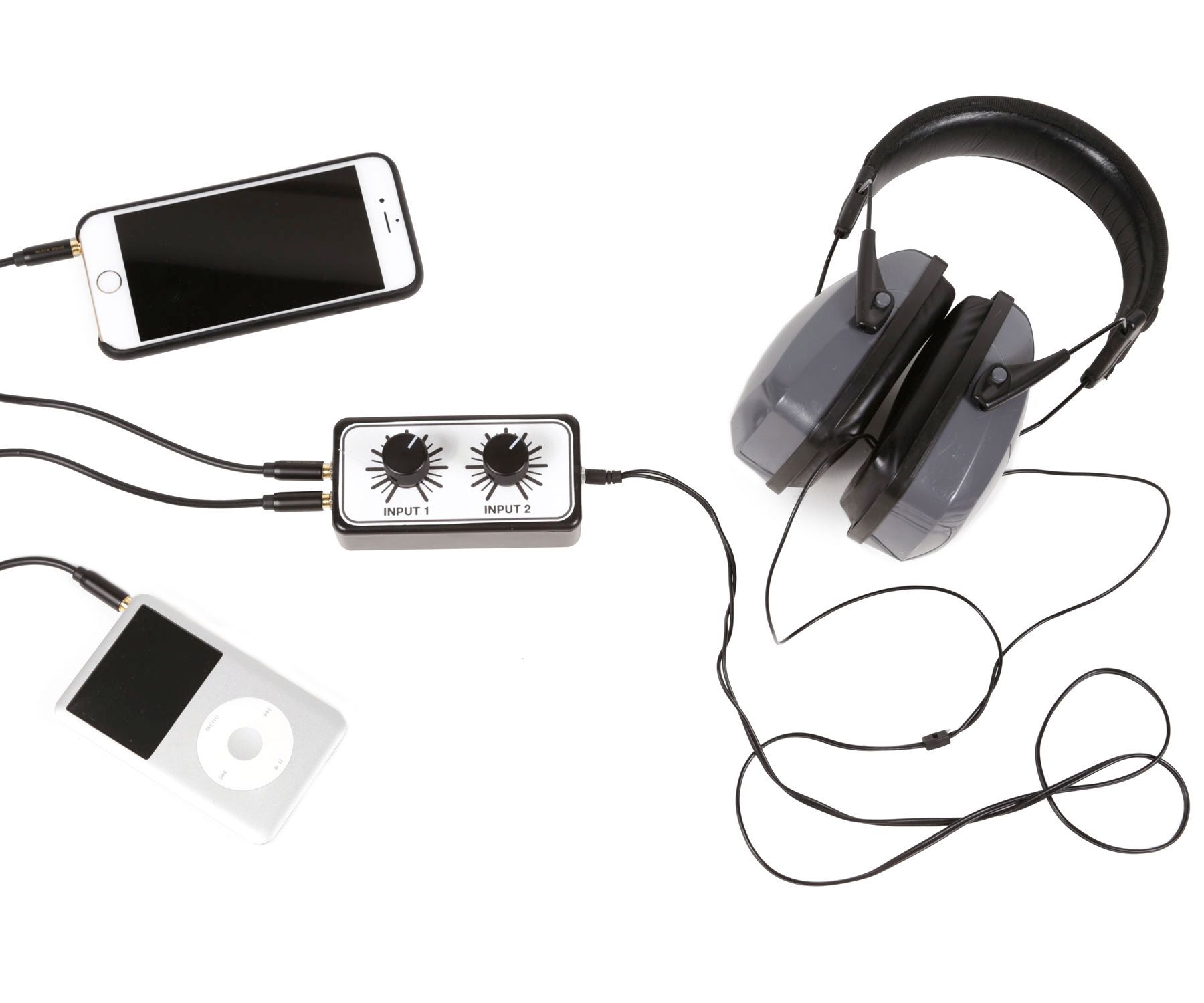
Instructables
Making an Audio Mixer: This simple passive DIY stereo audio mixer demonstrates resistors in use. When I say stereo, I am not talking about your home entertainment signal, but an audio track with a separate left and right channel.This mixer will allow us to combine two ste…
 remote pike
I have a project (finished) using circuit playground, I hadn't touched it for a few weeks and when I fired it up it wasn't lighting up all the neo pixels, I suspected a loose connection BUT it turns out reloading the code made it work... is this something that happens with the circuit playground if its left without power for a long time?
 upper coyote
That shouldn't usually happen after a few weeks, a few years maybe, but not weeks. By "hadn't touched", did you mean it sat there powered off, or it was powered and running, but nobody was paying attention to it? In the later case it might have been some software resource exhaustion.
 mild sinew
Does anyone know why my past two orders got cancelled?
 solemn field
mild sinew
Does anyone know why my past two orders got cancelled?
solemn field
mild sinew
Does anyone know why my past two orders got cancelled?
Order support is not something we can provide on Discord. Please email support@adafruit.com for issues with orders. Thank you.
mild sinew
solemn field
Order support is not something we can provide on Discord. Please email support@a...
I already did
solemn field
Unfortunately, we have no one with access to or control over orders on Discord. You could try posting on the forums, but I believe the response there will also be to email support.
mild sinew
solemn field
Unfortunately, we have no one with access to or control over orders on Discord. ...
Alright, np
 minor crag
anyone know of any dev boards available with the STM32H7 chip?
 vapid needle
This simple development board for the STM32H750 is a great way to add a powerful STM chip to your next project. Featuring the STM32H750VBT6, this chip has 1024KB of RAM, 8MB of QSPI ...
 pulsar shale
Can I use my U2F Zero (like a Yubikey) for multi-factor authentication on adafruit.com?
 karmic obsidian
WE ARE LIVE! ASK AN ENGINEER! https://youtu.be/bvvmqmwVcrk

ASK AN ENGINEER 5/19/2022 LIVE! This week it's on THURSDAY at 8pm ET!
Visit the Adafruit shop online - http://www.adafruit.com
LIVE CHAT IS HERE! http://adafru.it/discord
Adafruit on Instagram: https://www.instagram.com/adafruit
Subscribe to Adafruit on YouTube: http://adafru.it/subscribe
New tutori...
 thick prawn
I'm pretty proud of how much I've been improving at math
I've found a genuine love for it, and I'm finding myself making connections between what I learn with no guidance
In precalculus class I learned about the binomial theorem, and I realized it's what I needed to prove the power rule, and I solved the limit myself. It's not much, but I'm proud I'm becoming able to connect things like this
Such a great feeling
 steady gulch
yeah Maths rule ! 🤘
 steep yacht
Maybe not fresh or recent but question: Why the support of CircuitPython on ESP8266 was dropped? Is it due the low performance of the ESP8266 and low memory?
steady gulch
steep yacht
Maybe not fresh or recent but question: Why the support of CircuitPython on ESP8...
at the time Circuitpython moved to only support boards with native USB
steep yacht
steady gulch
at the time Circuitpython moved to only support boards with native USB
Ah, that makes sense
thick prawn
I taught myself good chunks of calculus 1 2 and 3
I’m in precalculus in school, but it was too boring. My dad taught me you get the most out of things when you chase them yourself, which definitely rang true this time
 slim warren
does anyone have experience with the clone versions of the MAX6675? Specifically, have you had any issues where I should avoid buying it?
 steel needle
But what does an adafruit taste like?
 inner linden
I somehow managed to pass enough classes to get a degree in math and computer science, LOL.
 rocky junco
tall gyro
Without knowing more I would suggest starting here -> https://github.com/Open-S...
rocky junco
tall gyro
Without knowing more I would suggest starting here -> https://github.com/Open-S...
This sounds like a really cool concept. To save battery even more, collar pings for a GPS location at timed intervals instead of all the time and if close enough to a WiFi AP, uploads to internet/local network.
 outer brook
Does anyone have a favorite JPG to Bitmap conversion tool? I'm using cloud convert which I have successfully used for other things in the past
 delicate quarry
Could be rfm95 or rfm96, I think they use the same pcb for both modules…
steady gulch
on the pictures the 95 is green and the 96 is blue, but 🤷 isn't it written on it ?
delicate quarry
Do the different color modules distinguish the module chipset?
steady gulch
and the 95 has writings on the shield
delicate quarry
Most likely a 96 I guess
Yeah the rfm95 has fcc certification info on the metal shield
I guess the rfm96 doesn’t because 433mhz isn’t a license free band in the us so US products would use the 95.
 woven crown
steady gulch
on the pictures the 95 is green and the 96 is blue, but 🤷 isn't it written on ...
woven crown
steady gulch
on the pictures the 95 is green and the 96 is blue, but 🤷 isn't it written on ...
no, it isn't written
 shrewd arrow
Hey everybody! I'm trying to connect my adafruit Rp2040 to my computer but it won't seem to pop up , is there anything I'm doing wrong?

There is also a red blinking LED labelled 13 in the corner I don't know if that is a part of the problem
 random cypress
outer brook
Does anyone have a favorite JPG to Bitmap conversion tool? I'm using cloud conve...
random cypress
outer brook
Does anyone have a favorite JPG to Bitmap conversion tool? I'm using cloud conve...
Any image editor. E.g. GIMP, MS Paint, etc.
steady gulch
shrewd arrow
Hey everybody! I'm trying to connect my adafruit Rp2040 to my computer but it wo...
hi, what are you trying to do ? have you looked at the guide ? https://learn.adafruit.com/adafruit-feather-rp2040-pico
shrewd arrow
Hi thank you I actually did solve the problem but I appreciate you linking the docs
outer brook
random cypress
Any image editor. E.g. GIMP, MS Paint, etc.
Oh I can just do it in InkScape?
 lost lily
outer brook
Does anyone have a favorite JPG to Bitmap conversion tool? I'm using cloud conve...
lost lily
outer brook
Does anyone have a favorite JPG to Bitmap conversion tool? I'm using cloud conve...
I find online sites pretty sketch lol
I use imagemagick, like ffmpeg but for images
random cypress
outer brook
Oh I can just do it in InkScape?
Inkscape is a vector graphics editor, you need a raster (i.e., non-vector) image editor
Since jpeg and bitmap are raster formats
shrewd arrow
Hey y'all I'm trying to turn on this display and have it say hello world but this red light keeps blinking and nothing is happening has anyone used the rp2040 on a display before ?
 hearty karma
outer brook
Does anyone have a favorite JPG to Bitmap conversion tool? I'm using cloud conve...
hearty karma
outer brook
Does anyone have a favorite JPG to Bitmap conversion tool? I'm using cloud conve...
I use GraphicConverter. It's great for bulk conversions, generating file icons, etc.
hearty karma
shrewd arrow
Hey y'all I'm trying to turn on this display and have it say hello world but thi...
It looks like those header pins aren't soldered, so they're likely not connecting reliably enough to control a display.
 main hemlock
@shrewd arrow ^this, you have to solder the pins
hearty karma
Or use non-solder approaches such as "hammer headers" or pogo pin clips
outer brook
hearty karma
I use GraphicConverter. It's great for bulk conversions, generating file icons,...
Thx!
outer brook
hearty karma
I use GraphicConverter. It's great for bulk conversions, generating file icons,...
Any idea if it can do SVG to DXF?
outer brook
Ah it's Mac only
hearty karma
I just noticed these show up at a surplus vendor: https://www.goldmine-elec-products.com/prodinfo.asp?number=G26442
 mental mica
hearty karma
I just noticed these show up at a surplus vendor: https://www.goldmine-elec-pro...
mental mica
hearty karma
I just noticed these show up at a surplus vendor: https://www.goldmine-elec-pro...
Thanks for the notification! Unfortunately, I’ve already got drivers & what I need is a controller
 pine igloo
Hey guys, how do you like my raspberry pi setup?
 pine igloo
cool
 gloomy mango
I do want one of those.. when I can order a Pi4.
hearty karma
mental mica
Thanks for the notification! Unfortunately, I’ve already got drivers & what I ne...
I normally use an MCU as a controller
mental mica
hearty karma
I normally use an MCU as a controller
that's kinda my problem from earlier-- I need to clock out 72 bits of data 8 times just to scan the display once
doing that constantly is a lot of work for an MCU that should ALSO be doing FFT
that's why I talked so much about needing a controller IC
gloomy mango
I got my hands on a Pi Zero 2W, so I'm going to install that into a keyboard.
pine igloo
gloomy mango
I got my hands on a Pi Zero 2W, so I'm going to install that into a keyboard.
good idea
let me guess... your gonna make a bluetooth keyboard*?
gloomy mango
I thought so.. 😁
I've got an IBM SK-8815, which has 2x USB ports.. so it will be easier to connect a mouse.
pine igloo
gloomy mango
I've got an IBM SK-8815, which has 2x USB ports.. so it will be easier to connec...
nice!
gloomy mango
Just need to figure out the wiring and retention mechanism.
hearty karma
Hmm, I would look at ways of offloading that work, like if the MCU has hardware SPI and the driver chip can work with SPI, or if the MCU is something like a Propeller or RP2040 that has auxiliary logic you can program to do stuff independently.
 junior pivot
pine igloo
Hey guys, how do you like my raspberry pi setup?
junior pivot
pine igloo
Hey guys, how do you like my raspberry pi setup?
Are you worried your Raspberry Pi might get slightly warm?
pine igloo
junior pivot
Are you worried your Raspberry Pi might get *slightly warm?*
nope
it's probably freezing right now🥶
 surreal pond
 glossy totem
that's terrifying
 wise sand
are there any diagrams/schematics available for this connector:
https://www.adafruit.com/product/5358

If you love power adapters or toys & gadgets that have magnetic connections, you can now experiment with these futuristic connectors easily. It's sorta like a DIY ...
I found diagrams for the 3 and 5 pin version but not 4 pin
and the 4 pin looks different from the 3 and 5 pin ones
 mystic quest
Sounds fun, you get to choose everything for example how it is controlled like bluetooth or wifi or something else. I made a wifi one before and I gave it a camera.
pine igloo
yeah I had the same idea
I'm gonna look for some tutorials to get a good foundation first.
mystic quest
That's a good way to proceed
This is what I used to control the motors, I like it because the extra pins are broken out so it's easy to add more hardware
https://www.adafruit.com/product/2348

Let your robotic dreams come true with the new DC+Stepper Motor HAT from Adafruit. This Raspberry Pi add-on is perfect for any motion project as it can drive up to 4 DC or 2 Stepper motors ...
mystic quest
It has good example code so it doesn't take long to figure out the motors.
Whenever I'm looking for examples of a project, I usually go with the one whose code I can best understand.
pine igloo
That makes sense
pine igloo
speaking of motors can you guys explain to me why these starts at 20-30$: https://www.pololu.com/category/172/6v-medium-power-mp-micro-metal-gearmotors ??

These medium-power (MP), 6 V micro metal gearmotors have a stall current of 670 mA at 6 V and a typical free run current of 40 mA.
can I get something better for that price or should I just eat the bullet and design my tankr robot around them since they soldered to the low-spec board?
they seems to include the gearing/hall sensor/rotary encoder in the brass part
hearty karma
I think the ones with the encoder have it at the other end of the shaft (one popular option has a magnetic disk mounted on the shaft)
pine igloo
but they are just brushed motor and low power ones so seems to me they are really really expensive and are being sold with a huge markup
similar brushed motor without the parts in brass costs less than a dollar
hearty karma
Technically, they're brushed motors with gearboxes. They have an assortment of different brushes (carbon, precious metal, etc.) and winding arrangements with different efficiencies. I would tend to believe these are higher quality motors than the cheap ones you refer to, but I can't be sure.
Carbon brushes on the left, precious metal brushes on the right
 pine igloo
Since this might sounds like an X-Y problem, just to give context to everyone, this is from a smart tank kit that costs me 180$. So I'm trying to find out how much I actually got because so far I have 12 parts on it worth 1$, those supposedly good 25$ motors (2 of them) , and a primitive cpu (atmel 32u4) that costs 3$
hearty karma
Those appear to be "oilite" style sleeve bearings.
pine igloo
So I'm trying to figure out how bad I got "scammed" and what I can reuse or not
the board have most of its pins used by on-board sensors too, so I only would have 8-9 gpios left on the atmel 32u4
if I uses these motors
hearty karma
The main differences I see in small DC motors are efficiency, lifetime, and mechanical rigidity. Which of these are important to you depends a lot on your use case.
pine igloo
I can post a pic of the pinsout if needed (it's going to be my next question anyway)
pine igloo
hearty karma
The main differences I see in small DC motors are efficiency, lifetime, and mech...
Well I just want to know, if for a tank, it's it likely that the price being shown for these motors have a correlation with their quality
or if a 1$ motor could replace them
hearty karma
Amusingly, I'm currently building a project using inexpensive DC brushed motors, but I'm driving them with an AdaFruit motor wing, so I just need two GPIO pins to send I2C commands to the motor driver.
pine igloo
I have absolutely no idea how to tell if they are quality motors to figure out if I got my money worth
If I knew I got 50$ of motors that are actually quality for the price I'd feel less bad about paying 180$ for the whole thing
And would be less angry at myself for the purchase
hearty karma
Again, it depends on your use case. If you need the gearing for torque/speed reasons, you'll need gearbox motors. If they're going to run frequently, you'll want motors that don't wear out too fast. If they'll be supporting mechanical loads on their shafts, you'll want motors with good bearings. If they'll be battery operated, you'll want high efficiency motors. And so on.
outer brook
If you run one of these micromotors at 4 or 5V, it should just run slower right? Sans encoder
pine igloo
well my use case is that I want to improve what I got so it meet my expectations
ie: being able to map a room by having range sensors or ToF sensors, being able to tell the color of a tape so I can do a track with actions depending on the colors
I clearly won't be able to put a pi and a camera on there because the tank is already slow and would get even slower with the extra weight
hearty karma
You can do a basic test for mechanical rigidity by just wiggling the motor shafts. If they're loose, it's probably not a high quality bearing. You can also measure motor torque, speed, and efficiency. Lifetime and other build quality is a little tougher (I'll often take motors apart to evaluate their windings, magnets, brushes, commutator, etc. but some motors won't work as well (or at all) after being reassembled (if they can be reassembled with the tools and skills I have)
Heh, when you said "tank", I read it like "fish tank" and was thinking you wanted motors to pump water or something. I only slowly realized you meant a tracked vehicle!
pine igloo
I can't remove the motors thought because they are dangling from metal wires soldered on the board and next to a hall sensor fused to the board
so if they move the on-board stuff will probably not work anymore
hearty karma
So I'll just reiterate that I end to consider Pololu stuff to be decent quality (I buy a fair amount of stuff from them, and they're nice folks as well)
pine igloo

so the idea is that I removed what I didn't like / didn't meet my expectations. The last issue is wheter the board is worth keeping as well since it comes with the motors
despite the lack of capabilities on it
I'm going to need to add at least 4 sensors that can sense the color of a tape under it, and possibly a rotating ToF sensor or a ultrasonic for each direction on a 2d plane
outer brook
outer brook
If you run one of these micromotors at 4 or 5V, it should just run slower right?...
Thoughts?
pine igloo
I'm not sure what you mean, the battery box is 4 AA batteries so it already run at 4.8V instead of 6V so it's slower already
I'm confused from mentionning encoder since they are built-in and the speed of the motors shouldn't affect it?
outer brook
Ignoring the voltage required by the encoder
hearty karma
outer brook
Thoughts?
Yeah, DC motors will normally run fine from a range of voltages, just at varying speed
outer brook
Perfect
hearty karma
The encoder is presumably powered by the logic supply, so as long as there's enough voltage to operate the CPU, the encoder should be fine.
pine igloo
Since we are getting into the subject, these are the pins taken by the motors and associated control (in pink)

so another alternative would be to put a more capable board and only send motor related command to the vanilla one
but that implies adding weight, level shifters and a 2nd power supply etc
Even if I removed the lcd and the front things my understanding is that for these, even if they seems free, they are connected to things printed on the PCB
so I can't use them because I can't remove their connections
The 3rd alternative would be to just donate it/recycle it and start my own from scratch.... 😦
what do you think ?
hearty karma
I'd just hang more stuff on the I2C bus
pine igloo
Yeah control is still a problem, an frsky neuron esc uses 5A and that's not even including the RC receiver. So so far i'd have to use a remote/cheap ir sensor
and if you wonder why frsky OpenTX neuron ESC it's because it's completely open(+ source of the firmware) and use an arduino based usb programmer to program it...
so I avoid the proprietary ESC from the r/c world
That's the third issue with the smart tank, I have to make a pre-programmed path kinda like LOGO turtles in the 1980s
anyway I think I know what I'll do, reuse what sensors I already have for this small robot
afaik I can't use any of the sides pins since they are all for onboard stuff, but I still have 6-7 I can use including UART
then use the motherboard style standoff to add a more capable board to get better options
And in the meantime prepare for the big wheeled robot project that would have 2 lipo batteries and could power those 200A brushless motors and openTX receiver/ESC. I'd even have the bonus that it could carry the zuma onboard for stealth/smaller operations and send it commands
hearty karma
Using 5A sounds like a power issue, not a control issue (or are you thinking of switching the power to the ESC?)
pine igloo
well with 4AA batteries I don't see how I can power the 5A/6V ESC for long, and there isn't enough space for lipoly or more AA batteries
and I don't think those micro motors can handle much more weight either
so I have a big space/power limitation that I wouldn't have on say a 1sf custom chassis with 2 lipolys if you see what I mean
 verbal aspen
Yeah, an AA cell will not be happy with a 5A load.
pine igloo
the best option would probably be to start on a much bigger robot with the solidworks license so I can 3d print the parts etc
but this is 800$ already for the lidar, the motors, the 2 lipolys battery with a charger, the weather-proof enclosure the pi4 and the camera...
verbal aspen
The Solidworks license alone would be much more than that cost, too. 😅
pine igloo
nah it's 99$ per year for a maker license
which is almost the full version, my makerspace has it for them
and I just did 2h of training on it seems very capable
verbal aspen
Oh, the "3DExperience" web version? Haven't tried that.
pine igloo
license terms are: "meant for personal projects and non-commercial use. Per our terms and conditions, you may sell items you make for a profit up to and not exceeding US$2,000 a year"
yeah, you can still save on the computer even if it's the web version and it has a connected module so I can access my parts from the makerspace if both of us has it
which would be the case if I had it (and simpler than storing it on their computers)
hearty karma
pine igloo
well with 4AA batteries I don't see how I can power the 5A/6V ESC for long, and ...
No, AA cells can manage maybe 1A. If you need more current, you'll need a more capable source of power.
pine igloo
if you have 5 AA batteries in parallel don't you have 5A ?
hearty karma
You can join EAA for $40/year and it comes with a Solidworks license. I'd do that, but it's DOS-only and I don't have any DOS machines.
pine igloo
Whereas Voltage is added in series
hearty karma
Yes, 5 AA cells in parallel could yield 5A (at 1.5V, which is likely not sufficient for that ESC)
pine igloo
hearty karma
You can join EAA for $40/year and it comes with a Solidworks license. I'd do th...
EAA annual membership is half of the 99$ anyway and there are very few chapters in Canada. Not sure what you mean by DOS-only, hardware requirements seems the same. But at the end of the day it would be the same cost and I wouldn't be able to do anything EAA related
But such an alternative is very interesting if you want to fly drones in Canada because Aeronautical clubs have their own laws which predates canadian drones laws and have private airfields
hearty karma
I mean Solidworks does not run on BSD, Linux, or MacOS
pine igloo
I know it's a side-topic but aeronautical club is a very good deal if you can't figure the drone laws/find a place to fly one
pine igloo
hearty karma
I mean Solidworks does not run on BSD, Linux, or MacOS
I'm on windows, my linux laptop is too underpowered to even works tinkercad anyway
and since the maker space I mentionned is only open 5h a week I'd maximise the time to do 3d printing
so it works for my constraints but probably wouldn't for most peoples
If someone want to read more about the exemption from drone laws I mentioned above in Canada: https://tc.canada.ca/en/aviation/reference-centre/exemptions-canadian-aviation-regulations-cars/exemption-part-ix-canadian-aviation-regulations It's for members of the model aeronautical association of Canada which have their own private airfields and airspaces around it so they have juridiction to decide on licensing and requirements to fly drones on their private properties
like the one close to me has a 11 miles airspace around their airfield
hey
Biggest difference in MAAC is: to fly above 250g you don't need a drone license, just to arrange a flight plan and spotter (another MAAC member)
I have been brain storming some ways to make my chassis for my car
but I'm a little stumped when it comes to getting my raspberry pi on my car.
should I use stand offs?
pine igloo
pine igloo
I have been brain storming some ways to make my chassis for my car
I'd strongly advise starting from an R/C chassis or a 1 or2cf weatherproof enclosure if you don't have one
and yeah that is what I advise, use a plate and standoffs
whats a "1 or2cf weatherproof enclosure"
you'll probably need to bolt the standoff and use a sprray on anti-vibration/anti-unscrewing compound to the screw too
1 or 2 cubic foot
ok
wait
If you use a pi because of the power it uses it kinda implies you'll use lipoly and those have a good size
I have been thinking of 3d modelling my case
and also that you will use big devices like a lidar or camera
with tinker cad
gloomy mango
Yarp.. best way, especially if you have a 3D printer.
pine igloo
pine igloo
I have been thinking of 3d modelling my case
I doubt 3d materials is solid enough for a chassis of that size
3d materials in the range of entry-printer that most peoples here can afford..
pine igloo
pine igloo
I doubt 3d materials is solid enough for a chassis of that size
oh, well what materials would you reccomend?
gloomy mango
Still good for prototyping
pine igloo
there will be lot of vibrations and if you use a 1/2cf chassis that implies 2-4 inches wheels which mean some good motors
pine igloo
pine igloo
there will be lot of vibrations and if you use a 1/2cf chassis that implies 2-4 ...
right
so probably a final product that would be a few pounds and in the range 20-30mph range
if your 3d printed chassis collide with something at this speed it will break for sure
so wood?
and the torque from the components screwed in will probably shatter it too
wood, thin hard metal like extruded aluminum, thick hard specialized plastics etc
gloomy mango
Only use wood for a chassis if your name is Morgan. 😅
pine igloo
Morgan?
wood can't really be 3d printed well or use modern fab machines either so you'll have to use classic tools/methods AFAIK
hearty karma
You can print pretty solid stuff with ordinary PLA. I'll usually use like 25% gyroid infill and several perimeters and I can bolt stuff to it and abuse it and it'll usually be fine, as long as I arrange my design so the forces don't concentrate on the weaker joints.
pine igloo
because obviously I don't mean balsa wood or MDF here not hard enough
hey wait
maybe ill buy a kit first
gloomy mango
Morgan cars are famous for wooden chassis.
pine igloo
then ill build it and get a good foundation
kits start a 500-600$ for a chassis of that size/hardness
I found a cheap one from the company Freenove
if you want I can provide you a link to semi-open 12000$ one with design document just so you get an idea of the enclosure/tools/materials used in serious robotic projects which I use as a guide along with the videos from youtube by dronebot workshsop and other suggestions from ishiro in #help-with-robotics
hearty karma
Quit being discouraging. There's plenty out there that can support a pi that doesn't cost hundreds of bucks.
pine igloo
yeah I already found some

Freenove 4WD Smart Car Kit for Raspberry Pi 4 B 3 B+ B A+, Face Tracking, Line Tracking, Light Tracing, Obstacle Avoidance, Colorful Light, Ultrasonic Camera Servo Wireless RC
that was the car I found
ah yeah you should have mentionned you didn't need weather-proof or 1cf when I mentionned those... otherwise the rest of what I said is useless
gloomy mango
There are plenty of modern tools for use with wood, including CNC... but, ehh.. I wouldn't.
pine igloo
for me with my small apartment if I can't take it outside it is useless
I won't have enough space to enjoy it
oh well I'm just getting started
so I wasn't worried about the weather
pine igloo
gloomy mango
There are plenty of modern tools for use with wood, including CNC... but, ehh.. ...
the x-carve CNC from my fablab and their other one that are in the 4000-5000$ range can't handle wood thicker than 0.4"
gloomy mango
Ooooffff
pine igloo
I mean hardwood here obviously like oak/pine
gloomy mango
My cousin built better for less. 😅
pine igloo
when I asked they suggested I use their stand linear saws/jigsaws/wheel saws instead of the CNC
gloomy mango
Yeah, very much depends on the job, innit.
pine igloo
@pine igloo these are great to learn, but you just need to understand the chassis and parts are the cheapest of the cheap
ok
but ya know you gotta learn first
There are a kits like these and they all use the exact same plastic wheel that last a few months according to the reviews
gloomy mango
I'm planning a not so small RC car build myself, but I think that will wait..
pine igloo
pine igloo
but ya know you gotta learn first
sure but it's a bit like building a computer, you can learn AND have an expandable chassis too...
pine igloo
pine igloo
There are a kits like these and they all use the exact same plastic wheel that l...
yep
pine igloo
pine igloo
sure but it's a bit like building a computer, you can learn AND have an expandab...
ok
so how do I get started
the biggest constraint on such a project is the chassis and motors. When you add weight the performance of the motors get lower
right
chassis limit space, motors limit weight
components limit complexity
sure you can build up but personally I don't think a rolling skyscraper is a beautiful r/c car
what
nvm
pine igloo
pine igloo
so how do I get started
well I'd get an arduino one, bare minimum thing so you will know what the like or not for as cheap as possible
for about half the price
an arduino car kit?
I really regret getting a zumo 32u4 because I didn't understand what the sensors did exactly and the chassis is very small which really limit expansion
pine igloo
pine igloo
an arduino car kit?
yeah
starts with the minimum to help you figure out what you want
besides if you build something bigger ... I mean camera/lidar already costs more than these basic kits...

FREENOVE 4WD Car Kit (Compatible with Arduino IDE), Line Tracking, Obstacle Avoidance, Ultrasonic Sensor, Bluetooth IR Wireless Remote Control Servo
how about this one?
Honestly I think they are pretty much the same. In Canada elegoo are pretty good at making arduino boards quality wise so I'd go with them, but I don't know the US brands
ok ill try ellego
This is what I'm going with after learning of the limitations of my first kit:

elegoo*
Hopefully I can carry my first kit inside it as well aand deploy it and send it command, that would be cool so it wasn't a complete waste
You can also check the manual of the elegoo fully (full documentation) before you decide to get it
some of those kits I couldn't even find more than 4 pages of documentation
bought solidworks 😦
mental mica
hearty karma
Carbon brushes on the left, precious metal brushes on the right
is it carbon brushes that give cheap DC motors that distinctive smell?
hearty karma
It turns out the carbon brushes are in the fancier motors. I'm guessing the cheap ones, it's either a little ozone from the sparking, or small metal particles evaporated from the brushes and commutators.
pine igloo
doesn't smell like ozone though, more like burned electronics
my guess has always been that since they are cheap they don't come with the option of having washed the chemicals away or the cleaning bath used on the recycled metal
whereas if you pay a bit more they had the step where they blow air on them to chase away the chemical smell
and if you pay 2x a bit more, they test them
Hello just joined the server because I need help with a problem on cicuitpython
anyone can help please?
just nopticed the text chat for that. nvm
pine igloo
verbal aspen
Oh, the "3DExperience" web version? Haven't tried that.
also before I forget , the hardware checker will fail for most peoples here because it check for a professionnal workstation with nvidia quadro pro or similar but Ive seen the current version run on an onboard graphic card
So I'd make sure to have a good windows PC with a good graphics card before you spend on it. It is a 3d modeling software after all
And I mean after all it is an industry tool that just happen to have an hobbyist license. So of course they check for a certified professionnal workstation usually used in the industry at machine shops and not a hobbyist machine
karmic obsidian
The Desk of Ladyada - S3 & Sample Sunday https://youtu.be/JBo326sv-_Y

This weekend we spent most of the days outside, but we did get to one new board! We already make a Feather with an ESP32-S3 8MB module. Espressif recently sent us a few reels of ESP32-S3 mini modules with 4M flash and 2MB PSRAM, so we are spinning a new version of the Feather for this module. It's pin compatible but since the modules look so ali...
 prime adder
Wow are my scopes ground probes connected to earth ground
Googling seems to say yes
Which explains some weird thing I was seeing… since I was shorting a bunch of stuff!
If that’s the case I’m glad I made this discovery before destroying stuff 😆
 astral lily
prime adder
Which explains some weird thing I was seeing… since I was shorting a bunch of st...
astral lily
prime adder
Which explains some weird thing I was seeing… since I was shorting a bunch of st...
You can easily find out by using a multimeter to test it. Continuity mode, one probe on measurement ground and the other probe on earth ground.
 inland pelican
Hello! Did someone use powerboost 500 basic for powering rpi zero from LiPo cell? When i try this there is a hum noise and after few sec rpi zero green led is off.
 carmine plover
Hey I don't have idea about this community, I just Redirected here by Python's Resources Page! Can you guys please figure out about this ?
steady gulch
figure out what ?
were you like auto redirected by a page ? what page then ? or is it about something else ?
pine igloo
have anybody here ever worked with chromium-browser on raspberry pi before? Having a really simple yet confusing problem,
So the problem is when i run the following command
chromium-browser --disable-translate --incognito --noerrdialogs knipklok.nl/appointmentv2.php?boxid=000&boxcode=0000000
in the terminal, it does open up the chromium with that URL but it only passes one (first) parameter to the browser
So like after executing that command, when i see the URL of the browser that opens up, That URL looks like this
knipklok.nl/appointmentv2.php?boxid=000
steady gulch
pine igloo
have anybody here ever worked with chromium-browser on raspberry pi before? Havi...
put quotes around the URL
the & symbol has a special meaning in the command line
(running a command in the background)
for example see: https://linuxize.com/post/how-to-run-linux-commands-in-background/
pine igloo
steady gulch
for example see: <https://linuxize.com/post/how-to-run-linux-commands-in-backgro...
Ah i see, Thank you very much
mental mica
hearty karma
Hmm, I would look at ways of offloading that work, like if the MCU has hardware ...
I wonder if an FPGA would be good there
if nothing else, it's an excuse to finally learn FPGA stuff-- it's next up in my CE Major
hearty karma
mental mica
I wonder if an FPGA would be good there
Yeah, an FPGA would be a good choice: they're good at that sort of thing.
 ruby dragon
YO im trying to make a keyboard input with a trinket m0 (SAMD21) and for the life of me, I CANNOT find the dam keyboard library in the IDE
eternal crow
Question on the small gps board, is it possible to setup multiple batteries for the gps to pull from?
pine igloo
Hey guys which electronics car kit should I buy?

Freenove 4WD Smart Car Kit for Raspberry Pi 4 B 3 B+ B A+, Face Tracking, Line Tracking, Light Tracing, Obstacle Avoidance, Colorful Light, Ultrasonic Camera Servo Wireless RC
or

FREENOVE 4WD Car Kit with RF Remote (Compatible with Arduino IDE), Line Tracking, Obstacle Avoidance, Ultrasonic Sensor, Bluetooth IR Wireless Remote Control Servo
@solemn field can you help me decide?
delicate quarry
pine igloo
Hey guys which electronics car kit should I buy?
The former requires you to provide your own Raspberry Pi, so if you don't have one on-hand for this, definitely go with the latter.
pine igloo
delicate quarry
The former requires you to provide your own Raspberry Pi, so if you don't have o...
I have one
delicate quarry
Otherwise, it really comes down to Arduino vs Pi. The latter is better if you're interested in hardware mods and microcontroller development, while the former is more open to advanced software modification and development.
pine igloo
oh
well I do need two litium ion batteries for the raspi one
and they are really costly
delicate quarry
You won't be able to play much with things like image recognition on an Arduino, for instance.
pine igloo
yeah
well I'm OK when it comes to coding but I think the raspi one will be too complicated
and plus ill get TWO arduino's!
delicate quarry
Both look like fun kits with solid educational offerings, but the biggest difference is what you want to do with them AFTER you build said kits. If you just want a toy to drive around, the Arduino kit is definitely more cost-effective, but if you want the benefit of an onboard Linux OS, the Pi can do a lot more without too much extra hardware.
Two arduinos?
pine igloo
yep
delicate quarry
Oh, the remote is Arduino-based too huh
pine igloo
delicate quarry
Both look like fun kits with solid educational offerings, but the biggest differ...
I want to learn and build off of the default
delicate quarry
Interesting.
solemn field
pine igloo
<@330227457296957440> can you help me decide?
Please do not ping admins or moderators unless you are reporting a moderation or Code of Conduct issue. Thank you.
pine igloo
solemn field
Please do not ping admins or moderators unless you are reporting a moderation or...
oh
ok
gloomy mango
Piduino
solemn field
Hello, members of the Adafruit Discord community. We have made a change to the name, and therefore the scope, of this channel. It is now the #general-tech channel. Please try to stay within the scope of the channel and keep the discussions to general technical related. If you have any questions, please post your question in #help-with-community or post there to ask for a private thread to be created if you’d rather not ask publicly. Thank you.
solemn field
solemn field
Hello, members of the Adafruit Discord community. We have made a change to the n...
ruby dragon
print("Hello, CircuitPython!")
really no way to change baudrate?
 forest vigil
ruby dragon
```print("Hello, CircuitPython!")```
really no way to change baudrate?
forest vigil
ruby dragon
```print("Hello, CircuitPython!")```
really no way to change baudrate?
You seem to have a lot of preconceptions as to what CircuitPython is supposed to be. I get it. There's a lot of adjustments going from "big hardware" Python to "little hardware" Python. I have been frustrated by its limitations too, but there's no call to insult what is really quite a capable environment and toolchain.
ruby dragon
forest vigil
You seem to have a lot of preconceptions as to what CircuitPython is supposed to...
you know I saw people suggesting this for driving a display, and it cant even change the buad rate . I have no idea how this language is capable when it cant even support interrupts
Interrupts are not some super advanced use case either, any reliable code would be using them for many operation
ruby dragon
forest vigil
You seem to have a lot of preconceptions as to what CircuitPython is supposed to...
also what do you mean by the terms little and big hardware? And if these are industry terms are they used often? This is just coming from my curiousity, I do love to learn new things
outer brook
ruby dragon
Interrupts are not some super advanced use case either, any reliable code would ...
To my understanding, true C style (and older) interrupts just aren't possible in Python anyway. Pythonic interrupts are obviously on the developer's radars ( see https://github.com/adafruit/circuitpython/issues/4542) for now, asyncio exists.
hearty karma
As far as I know, it can change the baud rate, but usually I'm talking to it over a USB link, so it's a moot point.
outer brook
hearty karma
As far as I know, it can change the baud rate, but usually I'm talking to it ove...
Yeah I'm not seeing really anything that says you can't. Maybe there's a specific place?
ruby dragon
This is clearly a less developed possibly slower language all the libraries in new stuff are being built for this I find that to be really annoying for those who are not learning but actually using these boards or learning and using these parts
I would like to know about any advantages to language has though
outer brook
You're free to research them.
random cypress
@ruby dragon, if you want help with something, ask for it. Please don't dump non-constructive criticism, no one on this hobby-oriented server wants to receive that.
ruby dragon
This is not a help Channel
outer brook
The beauty of an open source project is you are also free to add what you would like.
forest vigil
ruby dragon
also what do you mean by the terms little and big hardware? And if these are ind...
I have probably been programming computers since before you were born, so I may have a bit more perspective. I invented the term big hardware and little hardware for that one comment. For this discussion "Big Hardware" = 64 bit or even 32 bit instructions, Secondary memory in 100Gigs or more, primary in Several Gig or more, and perhaps 4 or more core processors. Like your current desktop or laptop. Little hardware has 32 bit or 16 bit instructions, Secondary memory of Several Gig, Primary memory of a couple Gig if you're lucky. For reference, when I started programming we measured our memory in Kbytes and had an 8 bit instruction width.
verbal aspen
Kilobytes? LUXURY! We used to measure our storage in cards, and our memory in magnetic cores! 😉
forest vigil
ruby dragon
you know I saw people suggesting this for driving a display, *and it cant even c...
If you are going to be working with interrupts, Python is probably not the language you want. For high-performance embedded work, stick with C and C++.
ruby dragon
forest vigil
If you are going to be working with interrupts, Python is probably not the langu...
unfortuneatly I really dont have the time and will to learn how to create HID reports from scratch, and the only lib I can get working for HID is the circut python one
but in the future though I will 100% heed that advice
forest vigil
ruby dragon
unfortuneatly I really dont have the time and will to learn how to create HID re...
CircuitPython and HID is great. I use it for a password typer and mouse jiggler. On several boards.
ruby dragon
yeah its really good
forest vigil
@ruby dragon As a general comment though, carefully read the learn guides and documentation Adafruit has bent over backwards to supply. It is densely packed and covers so many board variations, sometimes it can be tough to glean what applies to your particular case.
forest vigil
ruby dragon
```print("Hello, CircuitPython!")```
really no way to change baudrate?
I don't recall having a problem changing baud rates when I needed to.
ruby dragon
ok yeah, so that was more of a question that I made it out to be lol
forest vigil
verbal aspen
Kilobytes? LUXURY! We used to measure our storage in cards, and our memory in ma...
I am only a few years shy of having to program using hollerith cards. (magic marker diagonals across the top, lest your drop your deck?)
ruby dragon
HEY i used cards too
forest vigil
I did, however, use Teletypes for several years. 300 baud terminals? A luxury!
forest vigil
Cleaned a mouse's ball?
verbal aspen
forest vigil
I am only a few years shy of having to program using hollerith cards. (magic m...
Same. Cassette tapes were the oldest storage I actually used, heh heh.
hearty karma
verbal aspen
Kilobytes? LUXURY! We used to measure our storage in cards, and our memory in ma...
Same. Started with the front board, fully populated with 576B of RAM.

Now I'm in the process of writing a Python program to laboriously post-process the audio from the original cassettes and attempt to recreate the original data, using a variety of techniques including leveraging the built-in checksum of Motorola S-records to do heuristic tie-breaking of ambiguous data
I do use "big" hardware (2.2GHz 64-bit machine) to emulate a teletypewriter for said "small" (1MHz, 8-bit) hardware 🙂
forest vigil
8080? Z80? 6502? 6800? Oh, you did say Motorola, right?
hearty karma
Yeah, 6800
pine igloo
Hey all,
Wanted some of your opinions/help.
So here is what I wish to do.
Say I have “x” script that is meant to be constantly running.
How can I check from “y” script if this program is actually still running?
Considered maybe every minute or so it writes the current date and time to a file and then I can check that the time is less than five mins ago or something, however I will be having tonnes of scripts and that could cause issues.
Thanks all!
 solar pagoda
@forest vigil @hearty karma This is how we got our software before pc's were pc's

 jade dirge
I had a teletype printer with a punch tape reader but I never used the reader. First PC had 8" SSSD disks.
241k per if I recall
astral lily
pine igloo
Hey all,
Wanted some of your opinions/help.
So here is what I wish to do.
Say ...
On Linux I'd use "ps -A"; other operating systems, I'd look for the equivalent.
Is there a chart/diagram somewhere that lists all the different Adafruit product lines/terms and what they mean/are designed for? Feather, Wing, Stemma, QT, etc.
Usually there's some detail on individual product pages but it would be nice to see it all in one spot with the intent behind it all.
hearty karma
pine igloo
Hey all,
Wanted some of your opinions/help.
So here is what I wish to do.
Say ...
Many versions of Linux and BSD have system daemon support to run things automatically and restart them when needed.
hearty karma
solar pagoda
<@702658967398252604> <@348911944486486016> This is how we got our software bef...
You could make those today, if you wanted: https://www.solid-merch.com/flexi-discs/

A flexible, low cost alternative to vinyl. Easy online ordering, quick turnarounds.
hearty karma
solar pagoda
<@702658967398252604> <@348911944486486016> This is how we got our software bef...
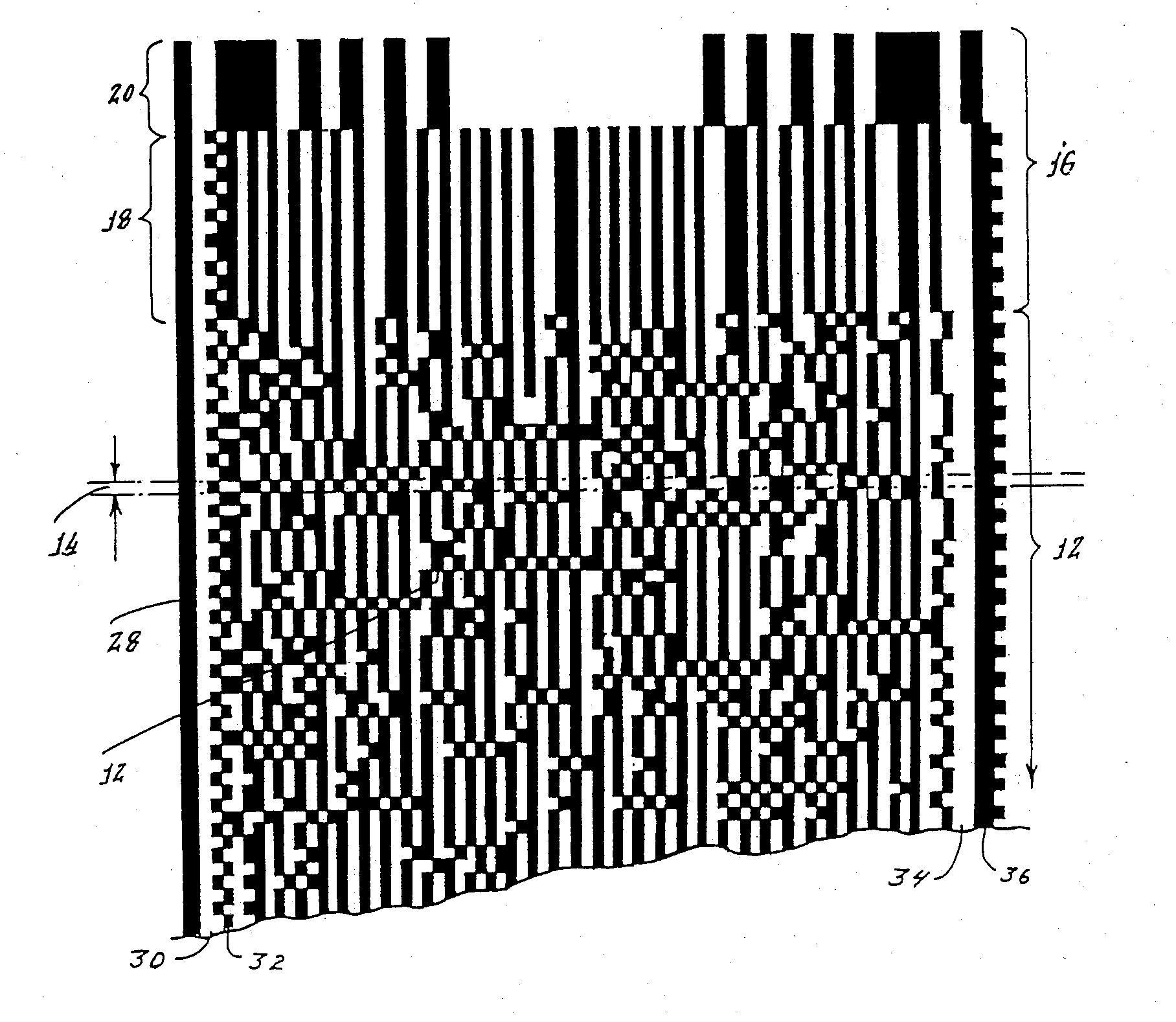
One shortlived idea was printing machine readable data in the magazines. One of the implementations was the Cauzin SoftStrip, which had an accompanying reader module to scan the data. https://www.insentricity.com/filedb/4/5/11654.png
 forest vigil
Be careful what you ask...
verbal aspen
Heh, that was a big step up from typing in code listings manually from magazines. I was thrilled when they started using checksums so you could be sure you didn't accidentally drop a comma. 😅
mental mica
fancee github feature: https://github.blog/changelog/2022-05-19-render-mathematical-expressions-in-markdown/

Render mathematical expressions in Markdown
they just added the ability to do latex-ish math equation rendering
(AKA: all PRs must now be accompanied by a mathematical proof)
main hemlock
@nimble prawn ^^
 drifting ice
...when you manage to properly apply thermal paste after cleaning off the CPU without making a mess, followed by finding the missing screws, reassembling the laptop, giving it a storage upgrade, and cleaning it of any dust successfully, finally turning it on with a full charge to boot, only to find that the touchscreen somehow got cracked.
-_-
pearl frost
pretty cool what you can get with relatively affordable thermal cameras these days

seek thermal + 20$ co2 laser lens = macro thermal
pearl frost

TEN-HIGH CO2 Laser Lens 20mm Laser Mirror CO2 Laser Focal Lens Laser Focus Lens, ZnSe for CO2 Laser Engraving Cutting Machine, Dia20mm FL76.2mm
you might play with different focal lenghts
then I just printed a little thing to hold that in place over the lens
pine igloo
pearl frost
https://www.amazon.com/gp/product/B01EMZD2DA
and the camera? (which was the most important thing for me since pi ones only do 24x32 pixels, ie: like an old-school rpg icon...)<
I expect that is still the same. Wish they offered a 300x260 like the one for smart phone that is 200$ but for the pi
pine igloo
astral lily
On Linux I'd use "ps -A"; other operating systems, I'd look for the equivalent.
Issue is I wish for it to be within the python code,
astral lily
@pine igloo I would still do the same thing, the syntax may just be a little different to call the system function. A quick web search for "get process list python" returns several ways of doing this across a few platforms.
pine igloo
Hmmm ye maybe, will any issues be caused because I have them run off one file? (Using the threading)
that is VERY interesting. Thanks 🙂
pearl frost
pine igloo
and the camera? (which was the most important thing for me since pi ones only do...

Seek Thermal | Affordable Infrared Thermal Imaging Cameras
High Resolution Infrared Thermal Imaging Cameras
inner linden
I really want a thermal camera of the sort I can't readily justify the cost of
astral lily
pine igloo
Hmmm ye maybe, will any issues be caused because I have them run off one file? (...
Not completely sure I follow but worth a try at least?
pine igloo
astral lily
Not completely sure I follow but worth a try at least?
Ye will do so
 minor hawk
Who do I contact with problems with my store account?
 vagrant gyro
minor hawk
Who do I contact with problems with my store account?
vagrant gyro
minor hawk
Who do I contact with problems with my store account?
please email support@adafruit.com
minor hawk
I have several times. I NEVER get a response from them.
vagrant gyro
minor hawk
I have several times. I NEVER get a response from them.
how long ago was your last email?
minor hawk
About a week.
I've filled in the webforms, sent emails and no response to any of them. This has been twice a week for the last several.
The site also says try discord. So I'm here and big surprise, there is still no way to contact anyone for help.
vagrant gyro
hmm. not sure. the email / web form was the correct route for this type of thing.
minor hawk
Guess I'm stuck. I'll have to take any business elsewhere since their customer service appears to be nonexistent to me at this point.
vagrant gyro
let me see if i can find out anything. and will respond back here.
forest vigil
minor hawk
Guess I'm stuck. I'll have to take any business elsewhere since their customer ...
Common advice: Did you check your spam folder(s)?
random cypress
mental mica
fancee github feature: https://github.blog/changelog/2022-05-19-render-mathemati...
Finally!
I mean it's perfectly workable without the support, and if you're writing lots of equations you're still better off just checking in a tex file, but what can I say, I'm a sucker for latex support 😄
A lot of other programming-ish tools have had it for a while, including Jupyter (and Google Colab). Afaik (please correct me if I'm wrong), it's not a heavy lift to add latex support to a markdown renderer. Mathjax and similar sophisticated web based latex rendering engines have existed for a long time.
 devout remnant
I am having trouble with the circuit python GPS library. The problem is in the gps.update command. On line 549 in the _parse_gsa section of the function, I am getting an error that "bytes" object has no attribute "decode" I am trying to run the "simple test" example
My setup runs the gps_echotest example fine. It outputs NMEA sentences, so I don't think it's a problem with the GPS
vagrant gyro
devout remnant
I am having trouble with the circuit python GPS library. The problem is in the g...
please re-ask this in #help-with-circuitpython
oh. nvm. already did.
devout remnant
Thanks, first time here.
pine igloo
Hey, I realized that I had this battle bots controller laying around doing nothing so I wanted to hack it to use as my controller for my R/C car. Can someone help me hack it?
 hearty karma
pine igloo
Hey, I realized that I had this battle bots controller laying around doing nothi...
hearty karma
pine igloo
Hey, I realized that I had this battle bots controller laying around doing nothi...
First you should try to figure out what it's using to communicate. Many are 2.4GHz radio these days, but there are some using a variety of other frequencies, and some use infrared light.
Look for any stickers on it giving information or an FCC ID.
pine igloo
it uses ir
 fallow hollow
I set up my two factor authorization with Authenticator, it took my code, set it up, gave me the authenticator adafruit account, but now it says the 6 figure code is invalid when I try to log in. Can anyone help?
I restarted my browser, (Chrome) cleared the cache, restarted phone and it still doesn't work. Firefox doesn't even recognise my name and password to get to the point of entering the authentication code.
solemn field
fallow hollow
I restarted my browser, (Chrome) cleared the cache, restarted phone and it still...
Try resetting your password. If that doesn't work, please contact support by going to https://www.adafruit.com/contact_us and submitting a request. We are not set up to provide account support on Discord. Adafruit Support will be able to handle that.
fallow hollow
I reset my password and it fails. I cannot submit a request by posting on the forum, the only way to contact tech, because I cannot login - because my authenticator code does not work, despite following all the directions. Any ideas? No existing posts on this issue in support.
solemn field
fallow hollow
I reset my password and it fails. I cannot submit a request by posting on the fo...
Email support@adafruit.com. I wasn't suggesting posting in the forums, they can't help you there either. As I said, we can't help you with account issues on Discord.
fallow hollow
OK. Thanks. Did not see that email address on their pages before.
 hollow meadow
Remember seeing an EEVBlog video on the Fluke 37. Old meter that's been lurking around the lab.

Very weird form factor. Very cool though.
pine igloo
heheheheh
That's just because a fluke is mid-range
high-end multimeters are still big boxes
hollow meadow
pine igloo
high-end multimeters are still big boxes
AHHHH but this isn't a desk multimeter!
pine igloo
this is an example: https://cdn.discordapp.com/attachments/327254708534116352/973426034491928616/10k_multimeter.jpg

 pine igloo
Like I imagine a guy you brag about your 2 flukes to
And he's like this isn't a multimeter THIS is a multimeter and he pulls out his keysight 3458 🤣
The keysight is portable too I guess. Would fit my backpack 😄
But at this price it would be in a brinks truck
hollow meadow
I like the Fluke 37 just cause they never made one this shape. It has a stand in the storage compartment
pine igloo
If I carried it around
hollow meadow
 pine igloo
oh that is very nice



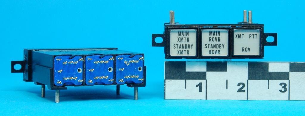
 pine igloo
I bet there are even worse one too, like for testing 720KV power lines
I mean the keysight one doesn't go above 5kish volt ??
hollow meadow
I've only dealt with 1KV tops. Maxed out my Fluke 87V
pine igloo
And the top voltage gloves stops at 36KV too. What do they even use if they accidently touch a 720kv power line ?
hollow meadow
They usually have pole meters, idk the name of them but they're on the ends of very long poles and don't need to be grounded.
pine igloo
Tried to get some class 4 36KV high voltage gloves to check if my allegedly 240V multimeter can actually works at 240 V but nobody want to sell me some 😦
hollow meadow
Sounds like you just need a safety squint
pine igloo
Like I was going going to test my 240V socket by sticking the test clips in it
holding the multimeter with these gloves
just in case
They say class 00 is good enough at 500V but just wanted a bit of a safety margin
hollow meadow
I just hold the probes with one hand and keep the meter on the ground :p
Other hand behind the back
(NOT SAFETY ADVICE)
pine igloo
well it's hard to put 2 probes in 1 socket with just 1 hand
hollow meadow
I am good with chopsticks
pine igloo
I mean the 240V ones are a bit apart vs 120V
And I'm going to need safety coat that cover my whole body for relays...
just in case I accidently rub against it since you have to remove the sleeves to put them in the relay terminals
hollow meadow
Oh you're planning on wiring while hot??
pine igloo
no, but when I test it it becomes hot
hollow meadow
Gotcha. You can also get alligator clips for your meter.
I use those when I don't want to be anywhere near what I'm testing
pine igloo
and since the thing that had socket receptacles with their relays is discontinued since 5 years I have to have the wires directly in without any protection...
hollow meadow
Yikes
pine igloo
Adafruit PowerSwitch Tail I/II would have been ideal for this
hollow meadow
I have a lot of old 80s relay sockets somewhere around here. Never really used them much but the relays they connect to are transparent which is super fun
pine igloo
these two are scary especially the 2nd one

Have to remove sleeves and stick the 3 part of the wire on these terminals. Even worse with the 2nd one with them being so close etc
I can imagine the electrical noise is very high on the 2nd one, don't think anyone serious would actually use the 2nd one for an actual mid-sized workshop/automation
also where the heat goes ?!
that seems much safer than the 2nd one...
 pine igloo
hollow meadow
I have a lot of old 80s relay sockets somewhere around here. Never really used t...
pine igloo
hollow meadow
I have a lot of old 80s relay sockets somewhere around here. Never really used t...
stuff like this ???
 hollow meadow
pine igloo
stuff like this ???
hollow meadow
pine igloo
stuff like this ???
Similar! Yeah
But not the same mounting style, I don't believe. They're more round. Not DIN rail mounted.
pine igloo
One that I could put a latch over that is like 1 inch would do too since there would be little wire left to brush against
but yeah a switch with the copper wires in the air, I'm not approaching that
pine igloo
huh why would a potentiometer come in joystick form with x-y-z axis ?!
I mean I know what a joystick is and that is probably less sensitive
But for me such a joystick is for moving spaceships in a 3d game not as a potentiometer...
hearty karma
Just for user interface options. Sometimes it's useful to allow someone to select 2 or more values with a single finger.
pine igloo
but behind the scenes it's a standard 100 to 10000 ohm potentiometer? How do you know which positions will give 100 ohm and which will give 10000 ohm (say you are using such a joystick to control how dim a led is for example even though that is overkill)
hearty karma
Usually you can tell by looking at the joystick how the internal potentiometers are connected. Some joysticks won't give a full range of resistance values as they're using ordinary 270° pots, but the mechanical limits only allow rotating it 90° or so.
There's also the old "try it and see" approach
pine igloo
ah I see 1 potentiometer per axis
hearty karma
I actually have some gimbal joysticks right here, as I'm building a custom R/C remote control.
pine igloo
I'd like one on my buttonbox/joystick project but wonder how good they are vs a gaming joystick
That is for the crane behind the tractor or flaps or attachments for a truck (like in snowrunner) so don't need to be super accurate but still
hearty karma
As with most components, there's a wide range of performance (and price). That's true with gaming joysticks as well (a surprising number of them are fairly cheaply made).
pine igloo
I guess if they don't have a ball in them or bearings they aren't that accurate/good
But still the joystick for a real-life tractor is 900$ so I wonder what it does more than a 200$ gaming one especially when it looks more primitive
hearty karma
You'd be surprised, some use some fairly amazing angular encoders (but they're expensive)
pine igloo
and I mean you don't have to precise to a mm in a real-life tractor when closing the jaws of a crane or farming implement
hearty karma
I suspect a tractor duty one is resistant to water ingress and vibration (and probably can operate even if there's some dust, mud, chaff, or seeds in it). We used to sell military trackballs that cost a lot of money, but they kept getting broken. We swapped them out for arcade duty units that were much cheaper, and they lasted longer. Arcade gear is designed for abuse.
pine igloo
I shouldn't have gone to this electronics site anyway, my wallet is melting every minute... 😦
I wonder how you put joystick and switches and other mechanical stuff back to an original position anyway
Seems like it would take powerful magnets or an independent circuit with a servo
ie: like putting this back to off when powering on
 hearty karma
The usual approach is simple springs
You can buy things like motorized potentiometers as well.
pine igloo
I guess my joystick project wont be as expensive as I thought after all 😄
hearty karma
SparkFun used to sell these motorized slide potentiometers: https://www.sparkfun.com/products/retired/10734

These motorized sliders are very cool. Each is essentially a standard slide pot which is belt-driven by a small motor. The slide contains two separate 10k
pine igloo
- these are so cheap I'll be able to make some mistakes and figure out what specs I actually need
hearty karma
I like it when that happens
pine igloo
For the tractor-grade joystick the lowest priced one was 200$....
I'd rather have a lidar/FLIR lepton 3.5 at this price...
If you can't tell as I explained in projects early I'm trying to have a couple of cheap different MCU and lots of parts
I had to repick all the parts of my sensor box 6 times and I can't take it anymore
Don't want to be limited by a lack of parts/MCU to test thing before I buy 4-5 of each anymore...
hearty karma
I like being able to grab useful stuff out of a box instead of waiting for it to show up in the mail. Lately, it's been handy when I wouldn't be able to buy the boards anyway due to chip shortages.
 pine igloo
And I mean even if 30% of the aliexpress quality stuff doesn't work (which give me soldering practice anyway) it's still much cheaper and faster than more expensive stuff
Im still waiting for it to arrive but I bought pretty much every d1 mini shield, really like the flexibility and the stacking stuff
hearty karma
I don't consider AliExpress "faster" (I'm used to 20-40 day shipping), but it's a great way to try stuff out, get weird industrial stuff, and have several copies of something I won't cry over if I fry it.
pine igloo
I mean the parts are already in Canada from aliexpress reseller at only like 30-40% markup so they get here in 2 days. Is what I meant 😄
hollow meadow
- have a look at LCSC as well
hearty karma
Ah, didn't know that was available, that's cool
hollow meadow
its basically the same as aliexpress but specifically for electronics.
pine igloo
I know they ordered 1000 of their stuff on ali express, so I know the quality isn't that good. But I mean if the markup is reasonable
pine igloo
hollow meadow
+ have a look at LCSC as well
thanks I forgot that one and couldn't find it anymore in the discord history search
also taiya in thailand
hollow meadow
(idk the full context of the convo i just saw aliexpress and know i switched to lcsc for some specific things)
pine igloo
bah lost the name...
hollow meadow
Yeah! It's owned by JLCPCB so its pretty useful. can export a BOM from JLCPCB to LCSC
pine igloo
the context is that I decided Id rather have a lot of common part to do projects even if they are very cheap
than wait/resdesign things 6 times because I can't find the premium parts or they are in shortage
hollow meadow
True! yeah, I have the curse of just scrolling through LCSC/Aliexpress and saying "ooh that looks cool" and buying it.
bad habit, but nice to have stuff on hand.
pine igloo
Like for these joystick project I was waiting to sign a contract to order these switches for me from an industrial resellers and etch them
whole thing for 24 buttons would have cost me like 600$
hollow meadow
good lord
pine igloo
but these 2$ rocker switches with DYMO labels will do just fine 🤣
and they look tough and industrial enough
hollow meadow
haha yeah I have a bag of like, 100 rocker switches from Ali, they're like 15c a pop but great for adding switches.
they're "rated" for 120v but I don't 100% trust that.
pine igloo
cant find a cheap blue keyswitch that is at least .5 inch thought
hollow meadow
hmmm
pine igloo
sounds like I'll have to fork the money for that
hollow meadow
like, a mechanical keyswitch or an actual keyswitch like a switch with a key?
hearty karma
I found some illuminated pushbutton switches at a surplus site, I figure I can laser print clear labels to fit under the keycaps and they'll look pretty industrial.
pine igloo
something like this for a switch
 pine igloo
this one is CNH OEM
with a key
Filling cabinet style key/keylock doesn't fit my need
hollow meadow
man the keyd switches are super cool. i put one in this stupid project where i gutted a UVC EPROM eraser and bolted it to the outside of a conduit box to make a surface cleaner
yeah, big industrial switches are expensive
hearty karma
I was thrilled to find the exact match for the key switch in an industrial laser at a surplus house: https://www.goldmine-elec-products.com/prodinfo.asp?number=G25165
pine igloo
at 30$ this is good but doesn't quit fit the looks (key is too metallic)

this is industrial grade, not really necessary for me, weaterproof, vibration proof, fire resistant 400VAC etc...
gold plated contacts , a bit too much for hobbyist
hollow meadow
D-SWITCH D-SWITCH S332-1-A3 US$5.2837
LCSC electronic components online Switches Special switch
- leaded datasheet+inventory and pricing
Schneider Schneider ZB2-BG4C US$5.9851
LCSC electronic components online Switches Special switch
- leaded datasheet+inventory and pricing
hearty karma
How 'bout these? https://www.electronicsurplus.com/unmarked-ym12-switch-key-7-position-master-key-or-3-position-op

YM12 Switch, Key.
7 Position Master key or 3 Position Op.
Mech: Panel.
Body: Overall 1.106
pine igloo
the s332 is too small, seems like 0.16 inch kinda like office filling cabinets...
instead of a big switch like there would be on a tractor/mining vehicle
hollow meadow
ah! forgot about the size requirement, haha
pine igloo
which are more around 0.5 inch or 0.6 inch diameter keyswitch
hearty karma

 pine igloo
7 positions seems a bit overkill, cant find the radius either. But that's already better on the looks of the key
pine igloo
hearty karma
https://www.electronicsurplus.com/pub/media/catalog/product/cache/b0b14895a4add0...
what is that? Looks like some serious electricity stuff
hearty karma
I love industrial looking switches, especially at surplus prices. It's available here: https://www.electronicsurplus.com/stacoswitch-im1562-switch-bank-contacts-3-position-each-dpdt

STACOSWITCH - IM1562 Switch, bank.
Contacts: 3 position each DPDT.
Actuator: PO, PO Illuminated.
Mech: 2.43
pine igloo
If I remember one one of the manufacturer (maybe e-switch the one you linked) doesn't have any keyswitch under a minimum large order
hollow meadow
dang, yeah, probably this one.
pine igloo
whereas apem the one I put a screenshot of I can order just one (the overkill one)
hollow meadow
Definitely starting to see the issue here, haha. these prices are crazy. surplus is def the way to go.
pine igloo
honestly Im hoping to find one from a used tractor on classified or something
hollow meadow
or junk yard perhaps
pine igloo
The holy grail would of course be to find an actual used panel/membrane panel from a new holland tractor
pine igloo
hollow meadow
Definitely starting to see the issue here, haha. these prices are crazy. surplus...
yeah and when you look at the datasheet there are included services* then later you see it's for 50000 minimum order
so I pay about the same price as these large order but I only get 1/10 of what is being described...
Speaking of which can a hobbyist print/cut something to get a membrane keypad in the end ?
hearty karma
Yup, there's not a lot to it.
pine igloo
Would be really handy for the mods that require lot of keys to use
hollow meadow
A jank solution could be to just print something to recess standard pushbuttons into suchthat the caps stick maybe a mm above the surface, then apply a membrane ontop of that.
pine igloo
Yeah I know I could laser etch plastic buttons and use pushbottons... but I dunno a custom membrane is a life goal in electronics that seems impossible
just like flir and lidar seemed impossible 15 years ago... these were dreams for me that I never thought would happen in my lifetime...
hollow meadow
yeah what they actually use are called metal dome pots. that's the little bits of metal that are attached to a pcb.
pine igloo
back then flir wouldn't even be sold to civilian or to companies outside the security sector
hollow meadow
they're stainless steel and are domed to flex and make contact with exposed plates.
pine igloo
so only way to ever play with one seemed to go in the military
hollow meadow
FLIR is some crazy stuff. every day im tempted to get a phone module.
there's even phones out there (industrial phones) with FLIR built in.
blows my mind.
pine igloo
yeah, I like it so much it's like the sole reason I want to splurge on a robotic car...
seems like a waste without being on a mobile platform
that's how some civilians earn money as well in Canada helping search lost peoples/animals/damaged crops too (except with drones)
seems custom membrane have similar prices to PCB
hollow meadow
ooh?
pine igloo
well I mean deluxe PCB
hollow meadow
You can also purchase the membrane springs themselves.
pine igloo
seems to start at around 20$ each, minimum of 10
hollow meadow
Oh wow, thats not bad then.
pine igloo
If you don't use too much colors and use the same membrane style as the ones in kit it's not that bad
pine igloo
jrpanel dot com
hollow meadow
danke
pine igloo
theres iks a led option, metal dome etc there is also snaptron but there is far more options
and they use the quality 3m back adhesives
hollow meadow
that's some good stuff. never thought of custom panels.
pine igloo
EEVblog #1282 - Design Your Own Membrane Keypad! talks about the process
seems also it's much less expensive to order them in parts rather than buy a very big one... ie a common trap is having them surround the space of an LCD screen
embossed will cost more as well (ie: can feel the icon on the button by touch) and metal domes so it's more "clickety"
comments/reddit also say they look out for you to simplify the design so it cost less in the end
some of the companies will also print some resistors with different values so you can use analog_read instead of using several pins etc
size/# of colors are really the expensive stuff
what sucks is that in Canada these sort of stuff isn't really mainstream so if you visit a business they will have min orders of like 100000
random cypress
They make cable reels for big outdoor extension cords. Why is it so hard to find a smaller version of that, suitable for indoor cable management of e.g. 10ft usb cables that I want to retract when I'm not using? Basically what I want is a bigger-by-a-little version of the Adafruit wire spool set (picture attached), i.e., a rod with one spool per cable. I can DIY it but I'd rather just buy it and I'm surprised it isn't easy to find.


 mighty condor
Hi! Any luck with the ItsyBitsy nRF52840 Express? I've built the bootloader, can flash programs (with Arduino even) but the example programs (with just ble) either behave weirdly/hang or return NRF_ERROR_INTERNAL on Bluefruit.begin(). It all runs fine if I flash the self-built S140 back on the device. Played with linker settings, which made it worse and I had to recover with openocd/picoprobe (soldering on the pads wasn't fun)
hearty karma
random cypress
They make cable reels for big outdoor extension cords. Why is it so hard to fin...
I found this at an industrial supply firm. The bars are individually removable for when I want to use the wire elsewhere or add rolls. Searches for "wire spool rack" bring up several options.
 random cypress
hearty karma
I found this at an industrial supply firm. The bars are individually removable ...
random cypress
hearty karma
I found this at an industrial supply firm. The bars are individually removable ...
Aha, the secret word was "rack"! I saw a similar thing at Home Depot, but they weren't selling it. And I didn't want to pay for the actual wire on the spools they sold, either (it was like $20 per spool). It would probably cost like $20 or less total to DIY this so I don't want to pay big prices. I'll keep looking into it, thanks!
(I don't need a wall mount and probably don't need multiple rods, I just need one rod with legs to stand on the floor and a few spools.)
pine igloo
does qt py esp32s2 works at all in wifi without ul antenna? cant find anything on this
main hemlock
pine igloo
does qt py esp32s2 works at all in wifi without ul antenna? cant find anything o...
there are two versions: one with a built-in antenna and one with an antenna connector. I think you know this. The latter without an antenna will have poor performance
pine igloo
poor performancenis fine but none isnt
delicate quarry
I would avoid using anything designed for an antenna without having an actual antenna unless otherwise specified. Not every device will function well, and some devices could potentially have more serious consequences. If you have enough familiarity with RF signals, you could evaluate the risk on a case-by-case basis, but I'd otherwise reconsider whether or not to use the device requiring an antenna.

Electrical Engineering Stack Exchange
People tell me I shall not use my CB-radio station without an antenna connected or it will result in damage of the device. Is this true and why is this?
If you are familiar with RF and transmission lines, the output impedance of the ESP32S2 modules with IPEX connectors are all 50ohms, though I can't conclusively say that the QtPy necessarily matches that.
Given the antennas Adafruit recommends, though, it's probably safe to assume that's also the case here.
pine igloo
i got the version without antenna port
so its not designed to operate with an antenna but its still wifi
which is why im puzzled
ie 5325. . 5348 is the one with an antenna port
delicate quarry
pine igloo
i got the version without antenna port
Oh, the one without an antenna connector has a PCB antenna built in, so you don't have to worry about that at all.
main hemlock
pine igloo
so its not designed to operate with an antenna but its still wifi
The antenna is circled

The antenna above is way smaller than the typical circuitous trace antenna:
 delicate quarry
Oh, that's the antenna? Did not know that.
main hemlock
it's a ceramic chip antenna; I haven't been able to find gain figures compared with a typical trace anetnna, but it does not seem to be a significant difference as long as both are well-designed (proper ground plane, etc.)
 uneven meadow
yo, literally asking for homework help at this point but i have a deadline in 4 hours, why is a 5ms time constant significant in an RC circuit?
my google skills are failing me hard
 upbeat elk
Tau = R*C. Used to calculate discharge/charge rates. Can be used to find cut off frequency
uneven meadow
yeee, im working in LT spice for this, but apparently 5ms tau is significant?
verbal aspen
Not especially... I mean, it's longer than a lot of things but shorter than other things. Not a magic constant of the universe or anything.
 icy moth
I got the best email possible for the part shortage
The BGA version of the nRF52811 was out of stock and I got a notification from mouser they came in stock so I snagged 5 🙂
I wasn’t expecting to be able to get them until later this year
So exciting
inner linden
So... You were on the ball for that one.
 fading hazel
I need help. The world is a dark complicated horrifying messed up place. Surely, someone on this server must understand what I am literally fighting against? Please don’t allow it to become fatal, there is so much more adafruit stuff I want to buy.
verbal aspen
fading hazel
I need help. The world is a dark complicated horrifying messed up place. Surely,...
Wanting to buy more stuff to hack around with seems to be a good sign to me, since it's creation- and future-oriented. 😁 Focus on the things that bring you enjoyment and which enrich your little corner of the world, instead of getting dragged down by the bigger things you can't control.
hearty karma
For a few dark months, I'd buy parts and amuse myself by restoring old broken equipment. It gave me something more-or-less useful to do, with tangible results for my efforts.
astral lily
random cypress
They make cable reels for big outdoor extension cords. Why is it so hard to fin...
It's hard to find retractable versions in smaller sizes because the value of retraction goes away under about 25 ft or so.
random cypress
astral lily
It's hard to find retractable versions in smaller sizes because the value of ret...
How do you figure? I'm looking to not have USB cables tangled on my living room floor.
astral lily
random cypress
How do you figure? I'm looking to not have USB cables tangled on my living room...
Cable sizes shorter than that are typically easy to coil by hand. Also besides power/air, the industrial uses are pretty limited, which is why you also don't see many, say, retractable speaker wire spools.
There is a somewhat niche market in live events where they have portable, crank-wind spools of common cables used in that industry, such as SDI, Ethernet, fiber, XLR, or DMX cable. But I don't believe I've seen any of those with spring-return feature of the retractable power/air reels.
random cypress
I don't need anything fancy. The idea is that I can turn the spool instead of doing the i.m.o. finicky task of coiling the cable by hand every time.
astral lily
Also the slip rings for any sort of mounted retractable design will destroy anything above probably 2400 baud in most cases.
random cypress
I'm talking about a cylindrical piece of plastic.
astral lily
So not something that retracts when you give it a gentle tug or that's always plugged in at the other end?
random cypress
...good point, I hadn't thought carefully about that. I do want it plugged in at the other end.
astral lily
That's where the slip rings come in. :-)
oh they do exist though! https://www.senring.com/usb-conductive-slip-ring/single-channel/um0155.html
SENRING UM0155 series USB3.0 signal slip ring,solid,OD15.5mm,specially used to transmit high speed data and can be combined to transmit various signal channels,have the advantages of stable signal transmission,no packet loss, no string code, small return
random cypress
wow nice.
maybe it's possible to use a design that's not a spool and get a simpler solution...
astral lily
You can do it without a slip ring, but I wouldn't expect the cable to last more than a couple dozen uses in that case.
random cypress
yeah, without a slip ring I can see that there's a lot of wear on the cable
maybe what I should do is just get a bunch of spools, no rod, and leave them on the floor.
and use them as hand tools to make it easier to coil by hand.
astral lily
Personally - I use hooks and hand-wind my cables. Everything from 6ft USB cables to my 125ft power extension cord
random cypress
(I just don't like hand coiling)
I think I'd rather roll a wheel than try to wrap a cable in a circle
astral lily
I didn't used to, but after practicing and doing it daily for a few weeks, I started doing it with everything
Not saying you have to - just a thought (and my personal management preference)
random cypress
yeah, I wonder if I could get that comfortable with it
do you have some kind of fastener to hold the coil together when you're done?
pine igloo
random cypress
(I just don't like hand coiling)
hand coiling as doing it with your finger or with a hand wire wrapping tool like jonard ones?
random cypress
pine igloo
hand coiling as doing it with your finger or with a hand wire wrapping tool like...
I was using it to mean turning a straight cable into a coiled cable with no tools
astral lily
This is the technique I use.
took me about a month to master it but now I can wind a 25-ft cable in about 15 seconds (never timed it, but maybe I should
Learn the proper technique to wrap all your cables to prevent knots and damage. The Roadie Wrap is the professional way to wrap all your cables. Check out http://makingmusicmag.com for more videos.
random cypress
lmao "overworked and underpaid"
astral lily
random cypress
do you have some kind of fastener to hold the coil together when you're done?
Usually Velcro
random cypress
yeah, that's what I use too
@nis pointed out a while ago that the over/under method in that video doesn't keep the turns parallel, but that's probably fine for me
astral lily
or the generic "hook and loop" fasteners, don't know if I own any Velcro-brand stuff
random cypress
I think what I'll do is somehow get my hands on a single spool and try out hand-coiling versus using the spool as an aid.
astral lily
It's true, but when I'm storing cables, my goal isn't parallel, it's quick deployment when I need it next, and cable longevity
random cypress
thanks for your advice, you probably saved me a lot of time!
random cypress
astral lily
It's true, but when I'm storing cables, my goal isn't parallel, it's quick deplo...
tbh I don't really know what parallel even does. is it something about inductance if you plug in the cable while it's coiled?
astral lily
I'm sure you could rig something up if you wanted a DIY retraction, like a string with a weight on one end or something
astral lily
random cypress
tbh I don't really know what parallel even does. is it something about inductan...
I think most frequencies that would matter don't make much difference if it's parallel.
Parallel could look cleaner aesthetically.
But if you're wrapping in a circle, truly parallel or just "vaguely the same size of circle in the same direction, you're not rejecting and EMI like 60Hz hum. If you want rejection, you'll need to wrap it figure-8 style. (That's generally how pros will wrap an analog audio snake if there's excess while in-use.)
mental mica


I spliced into my car’s overhead 12V, added a 5V buck converter, and used it to power a dashcam!
pine igloo
I'm a bit confused by firmware/bootloader/sketch
icy moth
pine igloo
I'm a bit confused by firmware/bootloader/sketch
What do you mean?
Like the difference between the three?
pine igloo
seems to be 3 separate things, but I can only do a sketch on an arduino ?
and if I changed my bootloader I'd potentially brick it ?
icy moth
Okay so firmware and sketch are essentially the same thing
pine igloo
and there is a sort of firmware as some sort of "BIOS"
icy moth
A bootloader on the other hand is a section of memory that handles startup, peripheral configuration and test, and whatnot
Usually you don’t change the bootloader unless it’s corrupt or you want a different base state
But firmware is essentially the code you design to run on a system that you use to enable/disable peripheral like i2c, SPI, can buses, configure other general purpose GPIO, set system interrupt event handlers, etc..
Arduino sketches is just a more specific term for firmware on Arduino devices
pine igloo
I answered a question before and they set their board put a led on high, and I said to save its state to ram and someone else said that the sketch could only run after what they were describing. Was it their bootloader that did that then ? If the software couldn't avoid this issue ?
icy moth
Right, a sketch or firmware runs after the bootloader runs
Bootloader are stored in what’s called bootrom
pine igloo
could you possibly tell a bootloader to permanently load a specific sketch even after powering down the device and back up ? a default one if there isn't any^
I got a new board that had a default sketch but it's gone permanently after I uploaded a new one so the default testsuite menu is gone forever
astral lily
pine igloo
could you possibly tell a bootloader to permanently load a specific sketch even ...
Not really because the available storage size for the bootloader is minuscule compared to the available storage size for the sketch.
It's conceivable, but probably not practical, that you could have something equivalent to a handful of lines of code that would execute within the bootloader space if it checks and sees the sketch area is empty
pine igloo
ok, when I look at the specs of a board how do I know how much space it has for a bootloader ? For instance for an esp32-s2 I seem to have to dig deep into the manuals for it
icy moth
Well, usually we don’t worry on ESP32 because it’s preprogrammed
pine igloo
Intresting esp32-s2 seems to have that capability to load a test firmware in production by modifying their open-source bootloader
icy moth
It’s not like an AVR/SAMX product that need a bootloader “burned” before it’s programmable
pine igloo
icy moth
Yeah, you can do that with microchip devices too
pine igloo
corollary general question as well, how do I compare 2 MCU from complete different companies ?
I'd like to a few cheap boards with various architecture so I'm not blocked on new projects by chips shortage etc
icy moth
Usually people compare RAM, Flash, peripherals, configurability, etc..
Available pins, buses, and how pins can be configured
pine igloo
but stuff like TI/STM are completely unfamiliar to me and I don't know to compare say a STM F3 or TI CC3320 to rp2040/esp32-s2/esp8266/uno/teensy 4.1/grand central m4 that I already know a bit
icy moth
Well, look at the data sheets and narrow down by suggested applications first
Usually ones with similar intended applications have similar specs.
TI MCU products for instance are typically intended for low power mix signal applications
Usually having decent DAC and ADCs on board
pine igloo
I guess I have an hard-time translating physical need to electronics specs
As a wonder if some boards are better at handling collision/vibration (being in a 30mph r/c car for instances) or if that is something you have to provide with the enclosure
icy moth
Usually there are ones specified for automotive design
TI makes some for that applications
But a lot of that comes to mechanical design considerations if you can use or find automotive grade parts
pine igloo
I mean I supposed very small ones like pi pico rp 2040 would work since smalller surface area and smaller mass usually mean less affected by force
icy moth
I wouldn’t say size is much if a consideration rather than solder quality, enclosure design for mitigation of vibrations and shock
Things like crystals are very susceptible to shock and it can either damage or skew the precision of the crystal if it’s bad enough
pine igloo
I guess I'll take a look at this. My current annoyance is that cheap small boards all seems to be 3.3V. Not many are 5V. Why?
icy moth
Lower voltage = faster clock speeds
So 5V has speed limitation as it gets hotter faster as faster clock speeds increases current consumption
Lower voltages mean we can get much faster speeds. Which is why you’ll see newer RAM and CPUs having core voltages around 0.9-1.2V
And when you overclock a computer, you’re adjusting core voltages
pine igloo
AH ah! That is why they have those 100mhz speed while my ryzen is over 2.6ghz...
by my ryzen is 1.3V or so
couldn't even power a led
icy moth
The good news is most CPU have 2.5V and 3.3V supplies to handle 3.3V IO
pine igloo
bah I seem to have a knack for always picking the wrong MCU for the job. And when I pick "right" there are tons of gotcha I would only have found out by reading(and having the time to do so) the manuals of 20-30 MCUs. Esp 8266 is a good example of what I mean
icy moth
There are plenty of great general purpose MCUs
SAM E/D 5x are great
Plenty of STM32 are great too
icy moth
 soft rune
can someone help me with an electronics question, pretty basic stuff
soft rune
can someone help me with an electronics question, pretty basic stuff
Best thing to do is ask your question and someone will help ya 🙂
We’re very welcoming here so no need to ask permission 🙂
pine igloo
I wonder how to ask a question about electronics IRL when I know they will approach the problem from the other end that I want to approach it and I already know their end won't meet my specs
icy moth
pine igloo
I wonder how to ask a question about electronics IRL when I know they will appro...
There are generally two schools of thought for engineering design, too down, and bottom up
Top down takes a highly specific product and seeks to break it down from the top in increasing complexity
Bottom up seeks to take an abstract idea and define a more broad idea in more specific terms
pine igloo
case in point: my r/c smart truck. I already know this:

I've been researching these different types of motors/angles and I doubt they can be bridged by now. The one that seems to answer my issue most is the R/C angle but I know makerspaces are former/active engineers/teacher types so they are going to go for the it's basicallty a custom small car angle and want to put recycled brushed motors on it
icy moth
So yours is a top down approach
pine igloo
Not sure, I mean if I can't figure the structure and motors it's not really worth starting for me
icy moth
You know the specifics of what you want so you are designing around those specifics
pine igloo
Trying to meet specs but electronics hobbyist motors can't seem to answer them unless I go with 2000$ per motor stuff from the like of honeywell or General electric or that german company I forgot that start with an F
R/C have been doing it for 30 years and seems to have exactly the power I need but are extremely proprietary. Just found a full spec document and it's not even PWM but PWM arrays under a deep layer of a custom protocol
Meanwhile someone broke with a junkyard would probably just get a 240RPM electric scooter bike 24/48V motor but these will be expensive in structural materials/etc and need dangerous acid batteries...
Maybe I should just tell them my design need 4x240W motors or one above 1100W and see what they come out with ?
really don't want to end up with a 800 feet per hour snail miniature rover like this NASA JPL one: https://opensourcerover.jpl.nasa.gov/#!/home

Build-It-Yourself Rover
Learn to build robots: Build your very own Mars rover at home!
The other difficulty I have with them if that they seem to think I shouldn't attempt such a complex and expensive project at the moment. But it's a life goal for me and something I dreamed of for a long time. All the other smaller/easy projects are "nice to have for me" but this one is much more important for me.
What should I do ?
icy moth
How big is this intended to be?
pine igloo
1 to 1.5 cubic foot. Should be enough for the two technologies I really wanted to experiment with in my lifetime 15 years ago: LIDAR and FLIR and a pi to be able to use them
would only be slightly longer than a cube (so something like 1.25 feet long, 0.8 feet large 0.9 feet high)
My plan so far is to start from a r/c truck and use everything except the chassis/gear system
Would like to use it outside during light rain, so so far it would be a weatherproof enclosure mounted on an extruded aluminium channels cage
Already got 2 ToF sensors for it, when the motors are settled I'll be able to design the construction in solidworks as I have the .STEP file for the enclosure and the channels
Makerspace is closed all summer so it's the last time I have to get the makerspace input before I start
icy moth
Gotcha. Seems reasonable to do with most COTS RC motors and whatnot
pine igloo
Of course I won't buy anything before I'm certain it can roll from a remote control transmitter safely and it's properly fritzed
It's just that when I'm certain for the motors I can finally take care of the next issue: gearing and temperatures
second option would be to get a slower r/c truck and all the smartiness would be in a towed trailer
would need to be slower to force-stop the main vehicle (proximity sensors instead of lidar, with an offset for the front of the main vehicle)
That way I wouldn't lose any warranty altering the chassis and since the trailer is unpowered it would be much simpler (and no complicated gear system)
pine igloo
Hi 👋 I’m new here and new to electronics in general. I recently designed my first simple PCB with KiCad and got hooked. Now I’m inclined to get more hands on experience doing a custom design based on the RP2040. I was looking at some of the Adafruit repositories as a learning resource but couldn’t figure out the BOM of these designs.
Specifically I was looking at https://github.com/adafruit/Adafruit-KB2040-PCB and https://github.com/adafruit/Adafruit-MacroPad-RP2040-PCB

GitHub
EagleCAD PCB files for Adafruit KB2040. Contribute to adafruit/Adafruit-KB2040-PCB development by creating an account on GitHub.
GitHub
EagleCAD PCB files for Adafruit MacroPad RP2040. Contribute to adafruit/Adafruit-MacroPad-RP2040-PCB development by creating an account on GitHub.
To validate my choice of Crystal and capacitors against what others are doing.
In the schematics and BOM I only see generic parts and the symbol for Y1 does not really match the footprint.
Am I missing something?
Are the actual parts include in these repos?
pine igloo

Adafruit Industries - Makers, hackers, artists, designers and engineers!
Adafruit is an Open Source Hardware and Software company. To that end, Adafruit has been working to submit many of their boards for certification by the Open Source Hardware Association. According …
Reading this, really sounds awesome 😺
I didn’t see any links to specific boards in that blog post. Is there a list of Adafruit designs that embrace the spirit of the Open Source Hardware definition somewhere?
Or is Adafruit committed to follow the Open Source Hardware definition for all hardware designs?
icy moth
They work to make as many of their designs open source as possible
As for BOM, you can extract part numbers from the schematic
pine igloo
I really like there is fritzing for a lot of adafruit stuff and 3d cad files
I might have to start making parts in fritzing 😦
can't find PFC8574 which is fairly common as an I2C extender...
@icy moth have you successfully done so?
hearty karma
Should be buildable
pine igloo
😦 😢
 pine igloo
hearty karma
Should be buildable
pine igloo
hearty karma
Should be buildable
Person on bike going to interfere with lidar and going to be laser bombarded though...
hearty karma
I'm not sure I agree. I can think of mounting solutions that would avoid interference, LIDAR doesn't have to be laser based, and low-energy laser beams are harmless anyway.
icy moth
pine igloo
<@728676724522352733> have you successfully done so?
Just open the schematic and brd files in KiCAD
pine igloo
I mean the rider is physically in the way for a 360o system
icy moth
You can import them directly into KiCAD which is super nice
pine igloo
unless you mount it on the top of their head

with a long wire that could get entangled in the wheel, chain etc...

That’s what I see with Atrium Viewer
I’ll try with KiCad
Just to be sure
hearty karma
If I go to DigiKey and enter 535-9857-1-ND it brings up the actual part, which is an Abracon ABLS2-4.000MHZ-D4Y-T, along with the datasheet and specs.
icy moth
Adafruit sometimes uses a generic part that shares a foot print
pine igloo
digikey interface confuse me so much
icy moth
I do the same
pine igloo
Like if I try to find an STM F41 there iss like 40 models and none of the MCU links to their dev board etc...
icy moth
Easier than having 30 different crystals to pick from if I’m just choosing based on size
hearty karma
pine igloo
I mean the rider is physically in the way for a 360o system
Doesn't have to be 360° and even if so, this is easily addressed with multiple sensors. I've routed wires on bikes in a variety of ways to avoid moving parts, it's not hard.
pine igloo
I thought of something like this once but I think it would take a lot of power to prevent me from going in a particular direction with the front fork or activating the brake
and would be easy to steal as well
The only big thing that seems realist to me as an hoverboard, compact enough so it won't be stolen since can be put in a backpack
and with the vibrations/shocks not sure ToF sensors would hold for very long
icy moth
pine igloo
I found this part with the Digi-Key mobile app. https://www.digikey.com/en/products/detail/ABLS2-12.000MHZ-D4Y-T/2001236
12MHz crystal pulled from that screenshot
pine igloo
Also I thought about it last night and there is no way I'm spending 1000$ on an r/c / robot truck project when bikes are 6k$ and fuel scooter are 2-3k$...
and high-end 250g drones are 900$...
icy moth
I’m planning on making an electric go kart now that I have the space to build
Just need to get a welder and some tools for working structural aluminum tubing
pine igloo
I might still get a 200$ rc but that is for the indoors 1/16 to 1/24 rc. Added bonus if I can actually drive the motors
pine igloo
icy moth
I found this part with the Digi-Key mobile app. https://www.digikey.com/en/produ...
I mean that’s my point, it’s a generic symbol
The specs for spektrum stuff is nice and all but the kit alone (batteries/1 motor/1 esc) comes to about 800$ which is insane...
It’s not the part that’s used
icy moth
Sure
Part of the schematic capture is picking the parts based on the data sheet
That specific crystal is suggested by the Raspberry Pi hardware design guide for the RP2040
pine igloo
Either I’m doing something wrong or this are not the sources for the actual board
I would just like to understand what exactly I’m doing wrong?
icy moth
Likely nothing at this point.
pine igloo
Before making unfounded allegations that is
Because as I understand it this is not in line of the open source hardware definition
Also, the git commit history looks very fishy
icy moth
But the schematic view is just that, gives you. A view of the circuit specifications
pine igloo
Again, I don’t think it satisfies the open source hardware definition
You don’t have any obligation to follow that definition, but claiming to do so and not doing it is, well, lying
pine igloo
Well that’s exactly what I’m puzzled about
pine igloo
icy moth
I’m planning on making an electric go kart now that I have the space to build
Problem with gas scooter/bike or golf cart is I don't have parking space 😄
icy moth
pine igloo
Well that’s exactly what I’m puzzled about
I personally wouldn’t read too far into it. Sometimes things seem off but that doesn’t mean they are. Open source allows you to see designs openly, but it doesn’t guarantee complete part parity
Especially because overtime parts might be made obsolete or discontinued, but that doesn’t make the design less open and accessible
pine igloo
is there something adafruit that looks a bit like this? kinda stuck since I cant fritz it :(
 icy moth
Open source is built on the premise that it gives to source full public view that can in many circumstances, altered by the end user for purposes that were not originally intended
icy moth
pine igloo
is there something adafruit that looks a bit like this? kinda stuck since I cant...
What is it?
pine igloo
Well that is exactly what I’m trying to do
icy moth
I used Adafruits designs as a reference, but I always seek out parts that work for my situation and skill level
pine igloo
I’m still not sure, are the parts there or are they missing?
pine igloo
icy moth
What is it?
PFC8574 I2C backpack for LCD1604
since this along with the LCD uses many wires it really ruin my schematic if I can't fritz it
so my plan is to hopefully start from something similar that has a fritzing part and change the connections. But I don't know the adafruit (sparkfun has a big fritzing library as well) gear well
fritzing has a pfc8574 but it's an unrelated chip without breakout
having the correct pins is much more important than the looks (different color is fine but not completely different shape)
icy moth
I wonder if someone has made a frotzing file for it
pine igloo
I looked for it but all I could find is peoples having unrelated circuit using the LCD but not the backpack
hum nvm I guess I didn't look hard enough 😦
icy moth
pine igloo
I’m still not sure, are the parts there or are they missing?
Here’s my advice:
I suggested pulling parts because usually they are available from the schematic but not always. Part of designing hardware is searching for parts based on your needs. So you would look up for instance a 12MHz crystal with 18pF load capacitance. And you’d pick a crystal that was like that.
The same can be applied to all parts
pine igloo
also I cannot name even one vendor who went open source hardware prior to Adafruit. ;)
afaic they lead the way. Period. ;)
I assumed most of the search results were the unrealted IC but I just had to add "expander" to the google search
@pine igloo Have you actually verified this yourself?
icy moth
If not, if you can find the board schematics and whatnot, you can creat fritzing objects through a very roundabout way
well, Adafruit started in before the major housing crash of 08
pine igloo

Translations: العَرَبِيةُ, Català, 中文, Français, Deutsch, Ελληνικά, עִבְרִית, Italiano, 日本語, 한글, Latina, Português, Español, Svenska The open-source hardware statement of principles and definition were developed by members of the OSHWA board and working group along with others. These documents were originally edited on the wiki at freedomdefi...
you're new. welcome. I'm not going down this avenue of pursuit any further. I think I've made it clear how I feel. ;)
bah it's not the correct one, it's lacking pins
normally it should hav as much pins as the lcd on the top part

also mine has the 4 left pins on the right side
icy moth
All I can say if you have questions about schematics or whatnot that you don’t feel are being answered well here, or you don’t trust the good faith of those who regularly reference Adafruit designs, you’re free to email Adafruit support and ask questions or ask during Desk of Ladyada on sundays
pine igloo
@pine igloo Well first of all thanks for your reply. Of course I respect your feelings, and you are free to feel whatever way you want. But that is not my question. What I am trying to understand is, am I doing something wrong or is Adafruit releasing incomplete design files.
I don’t want to be annoying, but I think that is a legitimate question
Rather than jumping to conclusions I would rather first want to understand the picture.
I think skerr is the exact person to be talking to, and that they already confirmed you'd doing nothing wrong (you have the available information 'already'). That's how it looks to me.
icy moth
Some parts are left generic from my understanding, mostly because the part they use might not always be available
pine igloo
You cannot just use an arbitrary crystal without specific resistor capacitor set up
icy moth
As for common parts like capacitors, resistors, crystals, it’s kind of pointless to put exact part numbers because there are sooooo many available
Adafruits design follows the RPi hardware reference design
pine igloo
They’re not using the same crystal as the basic example
icy moth
They offer a suggestion but don’t constrain you to that specific crystal
pine igloo
They are also not using the same Crystal as the pico pi
I'm a bit puzzled why you guys mention rpi and open-source in the same sentence
rpi is still completely closed/proprietary afaik ?
That was the big difference with arduino ?
;)
The RP2040 is somewhat well documented. I think it was received quite well by the usual vendors (Adafruit, Pimoroni, SparkFun &c.)
They all came out with boards for that chip.
to take the logic further, if they offer a hardware reference design while still being closed-source/proprietary I'd expect that to just be a a suggestion but lacking enough details/specifics so that someone could just copy them and take their market ?
At least I didn’t mean to make any statement about the raspberry pi foundation 🤷♂️
and hence resellers like adafruit would respect that restriction? (trade secrets)
All I want are the schematics. That's big.
so if there was any crystal in such a "suggested" design for an rpi I'd take it with a grain of salt and just a suggestion
because they are obviously not going to give out enough to have their business stolen ?
icy moth
The thing is open source doesn’t always mean you’ll know all the exact parts they use, if you want to know the exact part, email Adafruit or ask during ask an engineer
I use this crystal on my rp2040 design
I found this part with the Digi-Key mobile app. https://www.digikey.com/en/products/detail/ECS-120-18-33-AGN-TR/9648931
Order today, ships today. ECS-120-18-33-AGN-TR – 12 MHz ±25ppm Crystal 18pF 100 Ohms 4-SMD, No Lead from ECS Inc.. Pricing and Availability on millions of electronic components from Digi-Key Electronics.
It’s not in the specification but it works with the design well and it’s one I could get
pine igloo
I understand kbdev point thought for crystal it's not like a resistor where you can sorta replace it by mounting others resistors in series/parallel
since crystal are physical things that are custom grown
@icy moth with 27nF + 100k I guess?
icy moth
27pF + 953ohm
Series resistance should be around 1050ohm so that’s as close as I could get
pine igloo
1k I meant
Close enough
i mean for superconductivity crystal you just can't take a replacement, has to be the exact correct chemical structure and angles internally and a femtometric tolerance. I assume crystals for electronics are the same and you can't really have a big tolerance/same with lens ?
icy moth
Some people have omitted the crystal drive resistor for their designs and those work too
delicate quarry
Trying to match a product part for part is especially tough these days due to the component shortages plaguing the industry, so I wouldn’t be surprised if there were minor variations in actual part sources. Plenty of boards have had to substitute components due to sourcing issues IIRC…
pine igloo
To play devil advocate thought it's mostly a shortage for inexpensive parts
icy moth
And lots of microcontrollers..
pine igloo
Almost everything related to PIC/PLC seems to be really stocked well as well as high-end 1000$ boards or high-end 300$ motors...
pine igloo
pine igloo
To play devil advocate thought it's mostly a shortage for inexpensive parts
Maybe now yes, as the GPU situation relaxed
icy moth
PIC didn’t face the same shortage issues from what I saw
pine igloo
Like if I want a GE or honeywell brushless motor there are tons of them in stocks..
hearty karma
While jellybean parts (resistors, capacitors) are often going out of stock, they're easily replaced with equivalents. Some more specific parts (such as microcontrollers) aren't so easily swapped out. Personally, I consider crystals to be interchangeable parts.
icy moth
But samd/e devices from microchip? Still long lead times
pine igloo
My makerspace will even drive that get recycled electronics because of the shortage and offer bounty for some of them...
hearty karma
Huh, I should see if there's somewhere around here looking to recycle electronics. I seem to have accumulated a backlog...
pine igloo
hearty karma
While jellybean parts (resistors, capacitors) are often going out of stock, they...
Unless convinced otherwise, I still maintain that the released files are not in line with the Open Source Hardware definition.
pine igloo
hearty karma
Huh, I should see if there's somewhere around here looking to recycle electronic...
for a google search nearby, they might use the word "upcycle"
the 2nd makerspace in my city are often looking for almost any used stuff to upcycle in projects/electronic projects
delicate quarry
Inexpensive is relative. I prefer to think of it as parts with silicon semiconductor dependence
hearty karma
Makerspaces are thin on the ground around here. The most local one folded years ago, the next most local one doesn't have anything like that, and the next most local is a 45 minute drive each way.
delicate quarry
Freaking Xilinx fpgas and their 70+ week lead times…
hearty karma
pine igloo
The specs for spektrum stuff is nice and all but the kit alone (batteries/1 moto...
That's why I went with LemonRX. 3 ESCs for $40 is a lot more cost effective.
hearty karma
delicate quarry
Freaking Xilinx fpgas and their 70+ week lead times…
And closed source toolchain
icy moth
pine igloo
Unless convinced otherwise, I still maintain that the released files are not in ...
Feel free to contact OSHW to discuss their definitions of open source and how probably a majority of certified products don’t meet what you expect them to be.
Not to be cynical but it’s kind of a nitpick
main hemlock
@pine igloo Adafruit similar thing is https://www.adafruit.com/product/292, but it's not PCF8574
I'm not sure what your q is
pine igloo
main hemlock
<@456226577798135808> Adafruit similar thing is <https://www.adafruit.com/produc...
my question is that I have to fritz it and I can't find a fritzable part that kinda looks like it and has the correct pins
hearty karma
I have more of a beef with large commercial companies that use open source software (such as Eclipse or gcc) to build closed source software in violation of the license, than small companies that release open source hardware with a few missing details. If I'm re-using a design, I expect to have to do some engineering to re-create a manufacturable version.
pine igloo
If I can't fritz it I can't communicate well to other what I'm trying to do
pine igloo
hearty karma
I have more of a beef with large commercial companies that use open source softw...
and peoples who put .exe on github without any source 😄
Wish there was a way to report it, for me it's more bad than DMCA issues...
I may not necessarily agree. I think there is an agreement between the OSI and and OSHWA regarding trademark use. And as I understand it part of that agreement is what a user can expect from open source hardware.
github isn't an ftp site it's a source code hosting site...
especially when companies do it
hearty karma
pine igloo
Wish there was a way to report it, for me it's more bad than DMCA issues...
Oh don't get me started on DMCA, that's a giant mess.
pine igloo
Too controversial for here I think 😄
icy moth
pine igloo
I may not necessarily agree. I think there is an agreement between the OSI and a...
Look, it’s never going to be perfect. To expect it to be perfect is not really reasonable. Plenty of people have derived their own designed based on open sourced designs without issue. I don’t see why it’s an issue in this case
pine igloo
But feel free to start in DM if you want
main hemlock
@pine igloo the specific case of the crystal is that we've used a couple of different crystals there, in an effort to solve some startup problems. When the schematic was drawn the exact crystal wasn't known. In general if the exact part isn't specified it's because there are several possibilities.
icy moth
If you don’t know what crystal to use, ask for suggestions
That’s what the community is here to do, provide help
main hemlock
for instance in some cases we have had to substitute other parts (e.g. different flash chips)
pine igloo
another thing that annoys me, "chip shortage" but the MCU has tons of stocks, while dev boards using it aren't in stock....
So if you are rich and have access to industrial PCB making it doesn't affect you because you can still get the high-end boards or the MCU itself and print a dev board for it
I see it all the time on digikey...
delicate quarry
The point of open source hardware is to have some means of reproducing the hardware yourself. Even if the crystal has been substituted for another, the point is that the designs are accessible as a resource for anyone who’s interested. The exact part used on the schematic may not match the product 100%, but if they’re functionally equivalent it still serves its purpose.
icy moth
pine igloo
another thing that annoys me, "chip shortage" but the MCU has tons of stocks, wh...
Or the opposite with STM32 dev boards but no chips lol
pine igloo
hearty karma
I have more of a beef with large commercial companies that use open source softw...
@main hemlock Glad you answer. What I am puzzled about is, are the files on GitHub the files that you use for production. Or are these still stripped down version?
I also bet stuff like DHT11 will never be in shortage, they are kinda the electronic version of MTG lands 🤣
main hemlock
they are what we use for production. There are internal BOM lists used in the factory which specify which part, based on our own internal stocks
occasionally we get behind on publishing a board rev
icy moth
I saw companies were buying STM32 dev boards just to harvest chips so ST started limiting the number you could buy lol
pine igloo
icy moth
I saw companies were buying STM32 dev boards just to harvest chips so ST started...
I was in shock yesterday that pishop would let me buy 100 picos if I wanted yesterday ...
main hemlock
we don't strip info out of Eagle files before publishing or anything like that
icy moth
RPi Pico? I think there are a lot of Pico stock available so it’s probably not an issue to buy 100
delicate quarry
pine igloo
I was in shock yesterday that pishop would let me buy 100 picos if I wanted yest...
Rp2040 is in surprisingly good supply, to be fair.
Unlike the zero and 4b, there really isn’t a shortage in pico.
pine igloo
makes me sad when I compare pico / esp32-s2 with my uno rev 1 and rev3...
@main hemlock to be completely honest with you, the GitHub history does not look organic
Feel like comparing an IC chip that does the same thing to a giant-sized IBM electromechanic board from the 1930
main hemlock
there are internal repos; the design is copied to the public repo. The internal repos contain things we can't publish
delicate quarry
Oh yeah, 328p uses a much older production line that’s gradually being phased out in favor of the newer processes. The fact that they’re still in production at all shows how much they’re valued, though.
icy moth
Lol, you should see my board repos lol… definitely not looking organic
pine igloo
I use oregano, is that okay