
#general-tech
1 messages · Page 103 of 1
 plush jackal
 fickle grotto
oh wow! thanks for the resource there
so do I put this driver in any specific place?
plush jackal
Backing up a second. Download the SSD1327 library (you can find it in the library bundle on the CircuitPython.org) and put that library in your /lib directory on your board
Then you can peruse the bundle folder of examples and find the ssd1327 example.
Copy this file to your board and rename it code.py so it will run automatically when you boot up.
But you’ll need to modify this file to use SPI. I’ll look for an example.
 steady gulch
@fickle grotto what are you programming on ?
plush jackal

Adafruit Learning System
This cute little OLED is twice the size of out 128x64 OLED, plus it can do shades of grey.
fickle grotto
yeah I can see the SPI modifications. I'm a CS student so all the code is fine by me, I just have zero experince with physical component work. I'm using a raspberry pi B+ and a Zero W.
plush jackal
I’m not too familiar with raspberry pi so maybe someone else can help on that part.
fickle grotto
I mean the setup seems simple, I'll get into it now that I have all these proper resources. Thanks a ton :)
plush jackal
Not sure if code.py runs at startup on raspberry pi or what you have to do to run that code.
steady gulch
yeah so you are using adafruit blinka on a Pi, not a microntroller board (which is why you mentioned PIL)
fickle grotto
ah, yeah no prob. I can manage with the python/pi side of stuff
though I am starting to think I should get an adafruit board 🤔
steady gulch
I'm not familiar with using blinka unfortunately, I believe the circuitpython libraries are isntalled through pip
fickle grotto
yeah I've got them all sorted I think
fickle grotto
oh ill try that 🤔
 vapid wedge
I am generally unfamiliar with adafruit products after ~decade of change
fickle grotto
Yeah, that seems to work. I'm assuming that pip is grabbing from a general database of known scripts? as opposed to directly grabbing from a github raw url yknow
plush jackal
If you get no response here, you may want to query over in the help-with-raspberry-pi channel if you think any issues are specific to that. You’ll get a better audience than in general.
fickle grotto
yeah, sorry if I'm clogging up general chat 😄
steady gulch
yeah #help-with-linux-sbcs is probably your best choice
plush jackal
Not a problem, but just want to get the right eyeballs on your issue. Gotta run. Keep us posted in your progress and post a picture in show and tell channel if you get something displaying!
steady gulch
pip draws from https://pypi.org/ and github
fickle grotto
ah, nice.
steady gulch
I think you need to give it a repository with the appropriate info to get it from github
if it's not on pypi that is
fickle grotto
yeah, again im not sure of the inner workings but just a wget works for me 🤔
steady gulch
if it's not broken... 😉
don't change it !
wait...
oh there's https://pypi.org/project/adafruit-circuitpython-ssd1325/ (note the dashes replacing the _) but not 1327, seems this one is not published to pypi 🤷
oh there's an issue on that precise subject !
https://github.com/adafruit/Adafruit_CircuitPython_SSD1327/issues/8
fickle grotto
so If i grab the .py file off of the github, how do i "install" it?
like where do i put it lmao
steady gulch
in the same directory as your code for example, but the issue mentions that blinka does not do I2C displays, which means that driver might only support I2C and not SPI ?
fickle grotto
all the code ive seen seems to support both
plush jackal
You’re running SPI right, then use the four wire mode, it looks like it’s supported in BliNka. Gotta run, hope you can get a cat picture showing on your display!
fickle grotto
yeah its SPI everything, thanks @plush jackal :)
 dusk tide
So, I saw that the Pi Pico version of CircuitPython released with UART support. I had been running MicroPython on my PiPico, but wanted to move back to CircuitPython. I did so, and now the file system on it is broken. It mounts read only, and has a lot of garbage instead of a file system. It shows I/O errors, and fragments of files that I deleted in the past. Any idea how to fix that?
If I blow MicroPython back on it, it works fine. I can only read the device using Thonny though.
dusk tide
Odd, if I plug it into my windows box, it works. Just not on any of my linux boxes.
Oh, but as a one meg device. This thing has 16m flash, I think.
dusk tide
Well, that's a new one. I put it on the windows box, updated to the newest CircutPython and it came up telling me there were errors on the drive. I clicked the 'fix it' and it did. All is good now. No idea what really happened though.
Oh, and 2M on the board, not 16M. Not sure where I got that.
fickle grotto
So I got the display working.. kinda. The data seems to be sent to the display in an incorrect order or something. The display flashes and every other line of pixels is in a different position 🤔 odd
idk its all messed up
plush jackal
@fickle grotto strange. I read one comment somewhere to try a lower frequency on the SPI bus (lower baudrate setting?) and see what happens. If you can’t find the answer while googling add a question on help-with-circuitpython or raise an issue on the GitHub library.
 lofty steeple
Does anyone know if Adafruit sells a product similar to Velleman's Light Organ? https://www.eio.com/products/velleman-mk114-low-voltage-light-organ-minikit?variant=15310139457602&utm_source=bing&utm_medium=cpc&utm_campaign=**LP Shopping 2.0 - Catch All&utm_term=4586406599024318&utm_content=Catch All

EIO.com
Buy and save on Velleman MK114 Low Voltage Light Organ Minikit with fast shipping and unbeatable prices, you're good to go with EIO.com.
I'm looking for something like this that can translate an audio input (from an amp) into flashing light
 past axle
Hey Everyone! I have a 15 year old daughter interested in STEM, she would like an RGB led strip for her room. I'm thinking this would be a good way to introduce microcontrollers and hands on electronics. What hardware, neopixel would be recommended for a young teen?
 barren plaza
which programming language does she want to use?
past axle
She's had a high school class that worked through a bit of python so probably start with that
barren plaza
past axle
She's had a high school class that worked through a bit of python so probably st...
I'd recommend an M4 or better feather or maybe even the raspberry pi pico (rp2040 chip). An rp2040 feather is coming soon
fickle grotto
@plush jackal I tried modifying the buadrate and that didn't fix the issue. I then moved to trying to understand the display's initialization sequence in its driver to see if I could modify some hard-coded settings but I didn't get too far.
I finally went and downloaded some code examples I found from another source, and it worked! The code examples load up and everything, they do have their own driver though so that's odd🤔
There's just one last issue. The example code loads the screen quite slowly, it scans left to right top to bottom and takes a whole second to draw a whole new image. Surely this isn't its intended speed? All other resources I've found seem to get quite a good fps
past axle
barren plaza
I'd recommend an M4 or better feather or maybe even the raspberry pi pico (rp204...
Cool, which neopixel would pair well with a Pico? I tried to sort thru adafruits guides but quickly became overwhelmed!
barren plaza
I haven't used the pico myself, I just know that it has a lot of computational resources and it's the new hotness. I'm a big fan of the feather m4 and it is more mature. Which neopixel you pick depends in part on the power supply you can/want to use
 wise venture
I think it might be safer to stay away from the Pico for now, since CircuitPython for it is still under very active development
plush jackal
fickle grotto
<@366059101203202052> I tried modifying the buadrate and that didn't fix the iss...
Ok, if baudrate didn't help, then crank it up to a high value. I'm not sure what options are available, but explore what you can achieve. The baudrate may have limits, so I'd recommend setting the baudrate, then query the baudrate to make sure it accepted the value you requested.
past axle
wise venture
I think it might be safer to stay away from the Pico for now, since CircuitPytho...
Ok cool, that makes sense.
wise venture
I think maybe something with a screen on it, like the PyPortal, would be good
fickle grotto
Yeah it's seems as though if the baud rate is too high the display does nothing at all, but the upper limit still seems slow 🤔
wise venture
How much light does she want to have? To start with and later on?
past axle
I'll have to look into that. Do you guys know if there are any adafruit kits that would have everything, like neopixel, powersupply and controller, plus any required caps and resistors?
barren plaza
not that I know of
wise venture
This would be a good project, very few parts
https://learn.adafruit.com/pyportal-neopixel-color-oicker

Adafruit Learning System
Touch colored buttons to change the colors on your NeoPixel strips!
past axle
Probably Start with a meter or two
plush jackal
Strange that it takes a second to draw. With SPI, it's not going to be blazing fast, but 1 second sounds like a long time.
wise venture
But portal's out of stock. Let's see what else
barren plaza
is the titano out of stock?
nope! Titano is in stock, could adapt the project for the titano
would cost more though
past axle
wise venture
But portal's out of stock. Let's see what else
Yeah just noticed that its out of stock. Neat project tho
wise venture
Oh, here's a good one! And with the CircuitPlayground Express, which is a great starter "can do all the things" board
https://learn.adafruit.com/make-it-glow-your-first-neopixel-project

Adafruit Learning System
Get up and running with programmable LEDs -- no soldering required!
plush jackal
fickle grotto
Yeah it's seems as though if the baud rate is too high the display does nothing ...
Can you share your code?
past axle
wise venture
Oh, here's a good one! And with the CircuitPlayground Express, which is a great ...
Nice thats what I'm looking for!
barren plaza
you can also use its onboard sensors for cool things
past axle
barren plaza
you can also use its onboard sensors for cool things
Nice I like it. Her birthday is coming up hopefully she likes it too
wise venture
Exactly my thought @barren plaza. Start with lights, get lured with the possibilities!
barren plaza
just note that circuitpython uses a lot of the resources onboard and you might run into a wall if you try to do too many things, that's why I initially recommended the M4 boards but as @wise venture says this is a great place to start with ucontrollers
plus it has a cool form factor!
past axle
Cool
wise venture
I think that the display case for it would be a nice touch too
barren plaza
and CP is a great place to start too. Cool gift from cool parent!
wise venture
Sorry, enclosure: https://www.adafruit.com/product/3915
We've got nice cases for many of our beloved boards, but the Circuit Playground Express and Circuit Playground Bluefruit has been left out of couture enclosure game.Enter ...
barren plaza
I just wish they made a waterproof one, it would finish a project I've been halfway doing for years
wise venture
There's a snowglobe-like one: https://www.adafruit.com/product/3722
Not merely a snow globe, but a show globe! This custom container is durable, clear and round, with a large flat screw-on top and a press-fit rubber stopper. The stopper makes a nice seal, ...
Good luck to you and your daughter, @past axle. If you have any more questions or she runs into issues, the community here is always happy to help out! 🙂
past axle
barren plaza
and CP is a great place to start too. Cool gift from cool parent!
Hopefully haha, fine line between cool parent and dork parent lol
fickle grotto
plush jackal
Can you share your code?
Yeah, here's the code, it's all basically just the supplied example stuff:
image drawing code: https://hatebin.com/lwwqatrzrb
OLED_DRIVER: https://hatebin.com/gqtuonatdq
OLED dev helper: https://hatebin.com/mowbquwlfr
it's pretty straightforward
so im 🤔
barren plaza
past axle
Hopefully haha, fine line between cool parent and dork parent lol
they're_the_same_picture.gif
wise venture
past axle
Hopefully haha, fine line between cool parent and dork parent lol
If that were for me as a kid, it's the line between "cool parent" and "über-cool parent" 🙂
past axle
wise venture
Good luck to you and your daughter, <@!763501922837463050>. If you have any more...
Thanks!
fickle grotto
@plush jackal ah, after looking closer it seems at though between these two drivers I have: The one that works uses the display as a general SPI device, maually sending GPIO signals. Whereas the driver that kinda works but kinda doesn't uses displayio.
Could this be the source of the speed issues? I can't imagine that directly writing each bite through the GPIO is as fast as using displayio.
but idk 🤔
 urban coral
is #help-with-rp2040-pio for the Raspberry Pi pico or just some module
plush jackal
fickle grotto
<@!366059101203202052> ah, after looking closer it seems at though between these...
I don’t really understand the difference when you say “write through GPIO” vs displayio. Maybe post the examples of which is fast and slow and maybe someone here can give you some tips.
 fathom wagon
Does anyone know of a self hosted program with a web interface that lets you view images?
One that can display them in a slideshow?
 static stream
fathom wagon
Does anyone know of a self hosted program with a web interface that lets you vie...
static stream
fathom wagon
Does anyone know of a self hosted program with a web interface that lets you vie...
Nextkloud
fathom wagon
static stream
Nextkloud
There's a lot of programs with that name, can you link me the correct one?
static stream
fathom wagon
There's a lot of programs with that name, can you link me the correct one?

Nextcloud is the most deployed on-premises file share and collaboration platform. Access & collaborate across your devices. Your data remains under your control.
 vivid ledge
can someone give me a video on how to interface with bytes adding them subtracting them in circuits
 sinful edge
Is there any bad chemicals in an electrolytic capacitor because I just hooked one up wrong
 subtle folio
@sinful edge The electrolyte varies, but it may be corrosive. Clean your hands and anything else it might have got on.
I don't think any of them have anything super toxic
sinful edge
Ok
subtle folio
(and if you're feeling paranoid, try looking up an MSDS - material safety data sheet - for whatever capacitors you have; you may or may not be able to find one)
 real scarab
Did it explode?
If not, then it's probably fine. Especially if you weren't using very high voltages.
 zenith cape
I got a box of components at a local estate auction, it is full of electronic goodies a lot of newer stuff too... one thing I got that interested me is a small panel mount ammeter with a coil for detecting amperage. Looks exactly like this, https://www.ebay.com/itm/Panel-mount-Square-shape-100A-AC-Digital-Ammeter-Amp-Meter-White-LED-display/402674745820. It is a D16-22FSA model with no branding. I was intrigued by it, so I wired it up to 120V, cut a power cable and installed the coil, spliced with wagos and plugged into hot rework station and turned it on. It read 0.00A, while the kill-a-watt read a value near 5A. Anyone have any experience with this type of ammeter? Does the orientation of the coil matter? Insulation? I got 2 of these, they were both still in the box with a generic "Ammeter WHITE" label on the top, no documentation was around.
 ornate abyss
Is there a schedule for the live broadcasts. Specifically I'm trying to find out what time FTDoL is scheduled tonight (knowing full well that it's just a prediction of when it will occur, ha).
plush jackal
?showtimes
 worldly shaleBOT
Desk of Ladyada - Random hacker times
JP's Product Pick of the Week - 4pm ET Tuesdays
3D Hangouts - 11am ET Wednesdays
Show & Tell - 7:30pm ET Wednesdays
Ask an Engineer - 8pm ET Wednesdays
John Park's Workshop - 4pm ET Thursdays
Deep Dive w/Scott - 5pm ET Fridays
plush jackal
Probably around 8-9 eastern if memory serves me right, so called “ladyada o’clock”
 pine igloo
So im trying to create a static website (so websites like netlify can host it) but then also talk to an api where the static website sends info to api, api does some calculations, and then static website spits out the result. ik it's possible because i've seen it before, but does anyone know how to do that? I can host the api on my personal PC btw
zenith cape
@pine igloo are you saying the api writes HTML code to the server with new values? Rinse and repeat?
not sure how a static website can send data, because that would make it a dynamic website
pine igloo
Yea exactly, but somehow ik people that have done it
zenith cape
interesting, I am sure it can be done
steady gulch
well that's not a static website then
do you mean to use javascript to update the content of the page ?
zenith cape
it's a weird world we live in, apparently, https://www.cosmicjs.com/blog/how-to-build-an-api-powered-static-website-the-best-of-both-worlds

UpdateCheck out the Jamstack CMS knowledge base page to learn how you can use Cosmic to build a static websites site using Gatsby, Nuxt.js, Gridsome, and more.
...
but i agree, how can a dynamically updated site be static? You can have static HTML generated by API, but the generating part is dynamic. I guess you can return full blocks of HTML via API.
steady gulch
having a thing that generates a static site is another thing
so like, you have a dynamic site that manages the backend, and it triggers an update of the static site through whatever your static hosting service allows
zenith cape
Yes, I agree.
@pine igloo do you want the entire files to be generated each run of API, or just certain data to be updated?
pine igloo
certain data
steady gulch
circuitpython.org is generated from github by a bot, and uses javascript to allow for the language menu to let you download each version
pine igloo
so static website gives unique input every time, api does calculations, then static website displays output
zenith cape
@pine igloo seems that html, css, javascript and server-side API is all that is needed. Do you already have the API?
pine igloo
zenith cape
<@456226577798135808> seems that html, css, javascript and server-side API is al...
I’m going to create one with vercel
zenith cape
Check this, https://reactjs.org/docs/introducing-jsx.html from here, https://github.com/vercel/next.js/discussions/12373

A JavaScript library for building user interfaces

 main hemlock
You can ask that the job be posted on the Adafruit jobs board: https://jobs.adafruit.com/
Find maker jobs in 3D and CAD, Art, Design, Education, Embedded Development, Engineering, Fabrication, Marketing and Communications, and Web Development
 sand tiger
Question: I would like to charge a rechargeable coin cell battery (NICD or LIPO) with a small solar panel.
Is there a simple chip or circuit I could use for that? PCB does not have much real estate so it has to be very compact ...
main hemlock
@sand tiger We have a board you could take inspiration from: https://learn.adafruit.com/usb-dc-and-solar-lipoly-charger

also see other projects: https://learn.adafruit.com/search?q=solar%2520lipo
 undone minnow
Hi how would you have a tactile pushbutton power ON/OFF an arduino when pressed for 3seconds?
 viscid finch
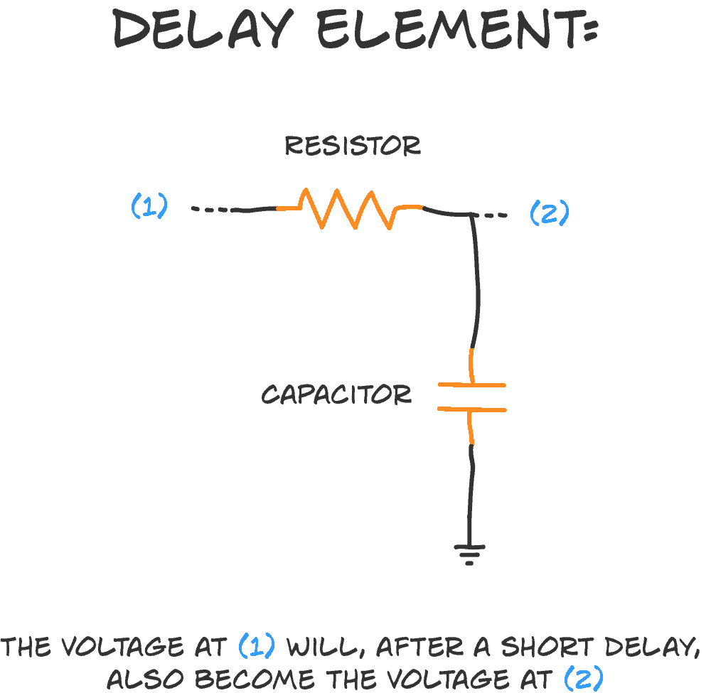
not sure if this would be the right solution for it, but you could use a capacitor delay circuit with a relay of sorts https://www.build-electronic-circuits.com/rc-delay-element/#:~:text=A capacitor is kinda like a tiny little battery.&text=And you can use this,one with a smaller value.
Build Electronic Circuits
The RC delay element is a way to create a time delay in your circuit by connecting a resistor and a capacitor. It’s super simple. And very useful. The ‘R’ is a resistor, and the ‘C’ is a capacitor. That’s where the ‘RC’ comes from. And here’s how you connect the two: How does it […]
undone minnow
Thanks @viscid finch
viscid finch
undone minnow
For the RC Delay @viscid finch when the capacitor is full you, would you need to discharge it?
viscid finch
you would have the relay or whatever is on the other side only flip when there's enough voltage
a relay won't flip until there's enough
viscid finch
though, there's a lot of variables to consider and I haven't built such a circuit before. The relay would drain from the capacitor as your feeding current into it and if you held it down for a while, it would cycle on/off
undone minnow
That's what I was wondering
viscid finch
is this battery operated?
undone minnow
Yes
viscid finch
what would be wrong using a latching button?
similar to this https://www.adafruit.com/product/482

These chrome-plated metal buttons are rugged and look real good while doing it! Simply drill a 16mm hole into any material up to 1/2" thick and you can fit these in place, there's ...
could probably do it with just relays as well
well, and the initial charge up with cap/resistor
one that stays on while holding, and then the flip flop
viscid finch
would be interesting to see if 2 relays and the charge circuit would work
 covert ocean
wise venture
covert ocean
wise venture
Hi @covert ocean. You're better off asking your question, so that those who aren't immediately around can answer in their own time. So it saves considerable time, especially for you, to ask and check back after a while to see if people have responded! 😊

 bleak ospreyBOT
Adafruit is now live! join us on https://youtube.com/adafruit/live

Come on by to see what's on our desk tonite: Some Quectel cellular modules came in, these may be used in our next-gen FONA boards. We also are getting ready ...
 karmic obsidian
Desk of Ladyada - RP2040 Feather prepares to take flight! https://youtu.be/qkN2TXqj59M
Come on by to see what's on our desk tonite: Some Quectel cellular modules came in, these may be used in our next-gen FONA boards. We also are getting ready to launch the RP2040 Feather - let's take a look at our nice silkscreen PCBs, and also how we're going to test and program these boards on the production line. There's some things we learned...
 fallow flicker

I went insane and wired a VGA cable to 14 darn wires, and it was torture
how do you guys do this
 inner linden
So, I guess you can say... not a fan.
plush jackal
Guess that’s not your biggest fan.
vapid wedge
I mean, all I did was very basic circuitry
then I tested it. It was not very good at sucking solder fumes from some distance away
undone minnow
viscid finch
what would be wrong using a latching button?
It's the size, can't be used on a mobile phone for example
undone minnow
viscid finch
one that stays on while holding, and then the flip flop
might do the trick
 pale steppe
for (float i=0.0; i<=3*PI; i=0.1){Serial.println (i<=PI?0:2} i used this function to print square wave in arduino serial plotter using atmega2560 but can not work on teensy 3.2 .what might be the cause? Please can some one assist me
 upper coyote
Well, the posted code is broken in several ways, so I doubt that exact code worked anywhere else. First in the for loop the "next" part sets to a constant which can never meet the termination condition. And then later you have a syntax error (grouping characters not matching).
pale steppe
@upper coyote it is able to upload onto the teensy but does not should the square wave
 wicked matrix
I wonder what that means
 inner linden
Gotta keep 'em separated, that's for sure.
barren plaza
[[STOCK CONFLICT]]: these displays are only for displaying the current $GME price
fallow flicker

update: i wired the 14 wires to a breadboard, resistors, then finally the Arduino
i managed to make Conway's Game of Life on my TV
fallow flicker
welp time to solder it all onto protoboard
 frozen wren
Which Aliexpress scope is half decent?
Trying to figure out how a video signal is being sent
upper coyote
@pale steppe Sure, you can upload any text (or probably even binary, if you gave it right filename); but if it's not a valid Python program, the interpreter won't do anything [good] with it. You posted a completely broken piece of code and asked for suggestions, my first suggestion was to at least make it valid.
pine igloo
HTTPSConnectionPool(host='www.google.com', port=443): Max retries exceeded with url: / (Caused by SSLError(SSLError(1, '[SSL: WRONG_VERSION_NUMBER] wrong version number (_ssl.c:1125)')))
Would anyone know why i'm facing this error? i'm currently trying to ping google with proxies to check the quality of the proxies through repl.it (im building an api that uses proxies)
plush jackal
barren plaza
[[STOCK CONFLICT]]: these displays are only for displaying the current $GME pric...
Did I miss the latest seven segment display Meme related to GME?
barren plaza
I was unaware of any 7 segment memes! I'm only cursorily following the GME craze
 hot grove
frozen wren
Which Aliexpress scope is half decent?
hot grove
frozen wren
Which Aliexpress scope is half decent?
Take a look at the ALM2000, it is a nice USB scope from Analog Devices, DigiKey sells them, For $100, and the SCOPY software is free. This is the kit that Analog sponsors, as part of their education outreach. Many colleges have their students use them for EE programs. It is quite useful for debugging all kinds of serial glitches, as well as run of the mill troubleshooting.
 pine patio
whats better- a 4k 120hz monitor, or a 8k 60hz monitor?
viscid finch
are you gaming?
pine patio
no
viscid finch
need more real estate, diagonal sizes of both, distance from, graphics card outputs? lol
pine patio
3 monitors is a mess, but what about 1 8k monitor as wide as your whole desk
that would be a 65" screen for my 55" desk
viscid finch
would that be too tall?
pine patio
gotta use the old neck
viscid finch
what about an ultrawide?
pine patio
you pay more for less
consumer tv form factor is the only way to pay a good price on a computer screen
viscid finch
TV's usually aren't as good for color accurate work
pine patio
im red shifting pretty hard anyway
viscid finch
I mean, it's possible it could work if you don't mind moving your neck around a lot (viewing angles might be of concern depending on the TV though) would also have to make sure your GPU can drive it
and we all know how GPUs are absolutely awful to get at the moment https://www.youtube.com/watch?v=jXHAGgdLbBw

What a way to start 2021, amd and nvidia gpu prices have skyrocketed like real real bad.Last Generation GPUs Like RTX 2070 are going for the same price as the 3090 and let's not talk about RX 580 which is going for 800$.
Track used:
Hey You, Wanna Connect with me? Here's where to find me on Social Media:
Discord...
pine patio
to drive 8k you need hdmi 2.1 which is only in 3000 series nvidia or 6000 series amd
rtx 3080 can drive it for 700 dollars
viscid finch
see above video lol
there's a massive GPU "shortage"
and there's a lot of scalping going on
viscid finch
doesn't help that miners want the cards as well
 desert cipher
yeah
 bitter gale
I don’t understand needing a highend card to run a blockchain miner woulda thought thatd need more cpu and ram than anything
viscid finch
thousands of cuda cores for parallel operations
pine patio
dang i dont see it for sale at any price
those dipwads should have priced it higher than 700, theyre leaving hundreds of dollars on the table
and real customers cant get them, just chumps who hit refresh on webpage
viscid finch
bots are buying them up, not people, well, people using bots to scalp lol...
pine patio
this feels idiotic even looking at dealing with getting a card that supports hdmi 2.1
viscid finch
yep
pine patio
monitors however, are available for the price they say
bitter gale
Yup welcome to 2021
viscid finch
I could actually probably sell my 4 year old GPU for a profit if I sold it now which is crazy
pine patio
gpus are just chunks of silicon, why is that the shortage and not the more complex monitors
viscid finch
different fabs/scaling
viscid finch
and more back stock
pine patio
i might wait tho. thing weighs 60 pounds and cost 2000 dollars
in a year it will be 50 pounds in 1200 dollars
viscid finch
true, could always use it as a 4k display in the mean time too
and then up the graphics settings upon having a new card
 soft walrus
what channel should i go to with help in soldering raspberry pi zero pins?
pine patio
can't even do that, available cards can only do 4k with displayport
soft walrus
because i'm about to start in the afternoon
pine patio
thats pretty general
pine patio
set the iron at 575 and do it
soft walrus
ok i should double check that the iron i bought can go that temperature
but i also bought lead free
pine patio
if it can't be set like that, it takes more care
lead free takes even more care and higher temp
pine patio
maybe 500 or 550 would work then
pine patio
those will get it done but dont have temperature control
viscid finch
you'll still want adequate ventilation
soft walrus
I can open up a door and have like 3 fans in my garage
pine patio
I use lead solder. its tried and true. never know what the new fumes will do
you spend a lot less time with fumes if you get it right and don't have to rework anything
the real danger is particles, not fumes
soft walrus
ok i'm just clumsy is all and i swear to god if lead gets on me i will have a mini panic attack.
pine patio
touching food after you have residue on your hands is a danger
soft walrus
right should wash hands
pine patio
the pine rosin fumes are not a big danger
the biggest danger is suction desoldering things
they blow a dust cloud of particles every time
pine patio
if you need to do a suction desolder, do it outside
it gets particles all over your work area
viscid finch
you should be fine with fans and minimal solder work
soft walrus
maybe i should just do it outside in general
pine patio
a lot of people suspect lead free is bad for your health in other ways
soft walrus
well shoot ;0;
pine patio
I've worked with people who have used lead solder everyday for decades without ever using a mask or especially good ventilation
pine patio
the stuff you smell is actually pine rosin
soft walrus
ah
pine patio
who knows tho, best to be safe
soft walrus
this thing i got from amazon does have tempurature control tho
pine patio
oh cool
soft walrus
so long as it gets the job done and the connection is proper
and i'm not getting lead in me
i'm not complaining
viscid finch
should be good
bitter gale
There is probably more lead in the water you drink that you will get from soldering anything
 limpid herald
As @pine patio said if you have adequate ventilation there shouldn't be any problem
pine patio
anyone know of something like this but less expensive? https://www.digikey.com/en/products/detail/protektive-pak/37750/1141236
Order today, ships today. 37750 – Tray Storage Corrugated Fiberboard 18.00" L x 11.38" W x 1.75" H (457.2mm x 289.1mm x 44.5mm) from Protektive Pak. Pricing and Availability on millions of electronic components from Digi-Key Electronics.
pine patio
I ordered one. interesting idea to use stackable project boxes that dont have lids
the box on top of it is the lid
pine igloo
I'm good with 6-gallon milk crates at USD $10/crate in lots of 12 crates. ;)
And then just cardboard boxes that fit inside milk crates.
I have one high-priority box with lots of red antistatic packing.
I discharge myself on any nearby metal object a lot more often than you would see someone do at the office where you work. ;)
If I were a tiny bit more serious about it I'd find more efficient means to enclose larger projects in anti-statics (similar to the large anti-static envelopes computer motherboards used to ship, in).
bleak ospreyBOT
Adafruit is now live! join us on https://youtube.com/adafruit/live

Watch the show here! Discount! https://www.adafruit.com/product/1980Visit the Adafruit shop online - http://www.adafruit.com---------------------------------...
barren plaza
woot!
 clever nexus
@pine igloo Milk crates make good bit coin mining enclosures. Lots of air flow.
wise venture
That's like 6 feet of cat60, right?
pine patio
milk crates seem kinda melty for holding things that could get hot
inner linden
...that's a lot of cats.
 thick prawn
What's the biggest mess you guys caused on accident?
I once set a transistor on fire, and had a portion of my house smelling of burnt silicon, and my table covered in some ashes
 flint swift
yo
pine patio
i blew up an outlet at college by not floating a scope
it burned off everything past the hole in the end of the plug and the outlet stopped working
the scope was fine
I went back to visit 15 years later and that socket is still broken
viscid finch
not really a big mess, but I shorted out I believe a webcam board using my multimeter ends since they touched/clashed (was a while back). Anyways, just be careful with that lol
 lost lily
thick prawn
I once set a transistor on fire, and had a portion of my house smelling of burnt...
lost lily
thick prawn
I once set a transistor on fire, and had a portion of my house smelling of burnt...
I burned a hole in a Arduino Leonardo clone because of a faulty servo. You could see the PCB through the hole in the microcontroller.
 regal pebble
Does anyone know if there are reverse mount "Neopixels"? I found this video from @humble jetty but she doesn't mention the part number or how it worked out. Ultimately I'd love to make a PCB with capacitive touch traces on one side and reverse mount RGB LEDs on the other. Covered with black LED acrylic I think it would be awesome, both for user interfaces and as a display panel...
 vagrant gyro
regal pebble
vagrant gyro
regal pebble
Thanks @vagrant gyro, I hadn't seen those, they look perfect!
Those will be fun to solder! 🙂
pine igloo
Is there a component that can restrict power flow from a battery?
Or something that will keep a device from turning on until some condition is met
Basically I need to be able to immobilize/reactivate an electric skateboard through a custom app
regal pebble
I think what you are looking for is a relay @pine igloo
Maybe similar to this https://www.adafruit.com/product/4409.
Just make sure you are considering safety @pine igloo, especially if this isn't something you work with a lot make sure you get some assistance
pine patio
you can use a p-fet to let something turn itself off
make it so a pushbutton or sensor can turn it back on, and once the mcu is booted it holds that line high
pine igloo
regal pebble
Maybe similar to this https://www.adafruit.com/product/4409.
that looks about right. It needs to override the authority of the main power switch on the device, as well as be able to be activated wirelessly
I’m really inexperienced in the domain of electrical engineering, so I’m not entirely sure of the difficulty in achieving this
regal pebble
It should be achievable @pine igloo but you'll want to work with someone who knows how to safely work with electronics. From a quick Google search it looks like electric skateboards run from 36V - 48V, which can give you quite a shock, and electrical shorts could cause fires or even battery explosions. In addition to the relay you would need a microcontroller and a way to talk to it.. typically either cellular, bluetooth, or wifi.
viscid finch
can't seem to find out the exact connector, does this bonnet https://www.adafruit.com/product/4132 use two of these connectors https://www.adafruit.com/product/4392 on the back?

The Raspberry Pi is an amazing single board computer - and one of the best parts is that GPIO connector! 40 pins of digital goodness you can twiddle to control LEDs, sensors, buttons, ...

Designing boards with plug-n-play connectivity is a snap, with STEMMA connectors. Here's a pack of 10 of our favorite 2mm pitch connector - the JST PH 4 pin. These are the ...
 idle mirage
Hey all, I'm a little confused about this solar charger's LOAD output voltage: https://www.adafruit.com/product/4755 It states it'll never surpass 4.4 V, but what is the minimum voltage it will supply before shut-off? I've been digging through the IC datasheet, but can't seem to find that info. Any help appreciated.

This charger is the only one you need to keep all your Lithium Polymer (LiPoly) or Lithium Ion (LiIon) rechargeable batteries topped up. No matter the power source at your disposal! ...
viscid finch
@idle mirage OUT - Regulated load output. This pin will provide a regulated output when the input voltage is below the over voltage protection threshold and above the regulation voltage. It will never be higher than 4.4V (but it may dip down to 3V or whatever the LiPo battery voltage is at, if USB/DC isnt plugged in)

Adafruit Learning System
You've got batteries, we've got coulombs
doesn't say it shuts off at 3v, but it looks like it might
idle mirage
Yeah that's what I wasn't sure about, but I suppose I'll just assume that's the shut-off point
vapid wedge
How do I know if I have an autoranging multimeter?
I have an MAS 830
I think it's not an autoranging multimeter
bleak ospreyBOT
Adafruit is now live! join us on https://youtube.com/adafruit/live

This week, everybody was MIDI fighting! Discussing features of the forthcoming MIDI project with the Raspberry Pi Pico. A look at engraving patterns for CNC ...
limpid herald
vapid wedge
How do I know if I have an autoranging multimeter?
If your multimeter is autoranging it doesn't show you values for the parameters you are measuring it only shows the symbols like AC Voltage, DC Voltage, Resistance, Current
bleak ospreyBOT
Adafruit is now live! join us on https://youtube.com/adafruit/live
This week, everybody was MIDI fighting! Discussing features of the forthcoming MIDI project with the Raspberry Pi Pico. A look at engraving patterns for CNC ...
 icy moth
The office is really coming together!
 wise venture
Wow, even have art on the wall? Someone's efficient!
icy moth
I’ve got a few things to unpack once my new work bench arrives 🙂
Fun fact, I took that picture of that Big Horned Sheep
 somber bloom
I just heard about the Raspberry Pi Pico getting Fuzix. I don't own one of these boards, but I do own other boards such as the Arduino and the Adafruit Clue. Has anyone thought of putting the os on these?
wise venture
icy moth
Fun fact, I took that picture of that Big Horned Sheep
Wow, nice job!
Also, have you considered weighing the carpet in your office now (or before your workbench arrives) and then in 1, 3, 6 and 12 months, to find out just how many parts and trimmed leads and such end up in there?
 hearty phoenix
Hi
lost lily
wise venture
Also, have you considered weighing the carpet in your office now (or before your...
Someone take a bet of how many pieces end up lol
And then use magnet to collect all the pieces
wise venture
Are most of the parts ferrous to some extent?
icy moth
the ends
pine patio
i just upgraded my desk carpet to the fluffiest one ikea sells
ive already lost a soic8 breakout
steady gulch
don't you fear static electricity ?
pine patio
air is humid enough ive never been zapped at this location
ive got an anti-static project tray coming
you won't want to see my winter desk pad if you hate static
 wise venture
What kind of animal caughs up a hairball that size?
wise venture
Must be nice and toasty
pine patio
its more fluffy than imaginable
 vocal vapor
Any idea on when the 10A 5V power supply will be back in stock?
 solemn field
@vocal vapor Nope. Sign up to be notified and you'll be among the first to know 🙂
viscid finch

Mouser Electronics
viscid finch
nah
steady gulch
you can look on Digikey too
pine patio
mouser and digikey used to have a minimum where there was a 20 dollar fee if you went under but i think they stopped that
vocal vapor
Well, two of those is $45 + tax, so no worries
Also, I screwed up. Ordered relays for a project, and accidently ordered Single Coil Latching instead of normal ones. So, have to spend $70 on new relays as well
viscid finch
the joy of prototyping
spends money, oh, these won't do what I want, oh well, I'll use them in another project ha
 spare summit
Does anyone have suggestions for cameras to use for streaming / project videos? I'm going through Amazon for webcams and they've all got these nasty critical reviews about how bad the quality is, faulty drivers, etc etc.
 coral moat
Unpacking kernel headers oh lord shoot me, this is taking forever.
Operation was interrupted before it could finish WHAT??
wise venture
I guess more than 6 eyebrows were raised during Scott's appearance on the Tom's Hardware show!
https://www.tomshardware.com/news/circuitpython-bootable-os-raspberry-pi

Tom's Hardware
Regular Raspberry Pi could act like a microcontroller.
barren plaza
but how many socks were blown off? even number?
viscid finch
@spare summit could potentially use a smartphone camera. They tend to be pretty decent quality (I'm using the NDI HX camera app but there's a lot of other apps). There's a small amount of latency over the network, but pretty alright for the most part
another option is to use something like a GoPro with an HDMI capture card
wise venture
barren plaza
but how many socks were blown off? even number?
Is "42" an appropriate answer here?
barren plaza
it is the answer to life, the universe, and everything
 calm snow
wise venture
I guess more than 6 eyebrows were raised during Scott's appearance on the Tom's ...
calm snow
wise venture
I guess more than 6 eyebrows were raised during Scott's appearance on the Tom's ...
hoping it will be a self-fulfilling prophecy
karmic obsidian
SHOW and TELL 3/3/2021 https://youtu.be/jN87Lz4fI-4

Visit the Adafruit shop online - http://www.adafruit.com
LIVE CHAT IS HERE! http://adafru.it/discord
Adafruit on Instagram: https://www.instagram.com/adafruit
Subscribe to Adafruit on YouTube: http://adafru.it/subscribe
New tutorials on the Adafruit Learning System: http://learn.adafruit.com/
-------...
 keen lichen
wise venture
I guess more than 6 eyebrows were raised during Scott's appearance on the Tom's ...
keen lichen
wise venture
I guess more than 6 eyebrows were raised during Scott's appearance on the Tom's ...
Thanks for the link!
bleak ospreyBOT
Adafruit is now live! join us on https://youtube.com/adafruit/live

ASK AN ENGINEER 3/3/2021 LIVE! Visit the Adafruit shop online - http://www.adafruit.com-----------------------------------------LIVE CHAT IS HERE! http://ada...
karmic obsidian
WE ARE LIVE! ASK AN ENGINEER! https://youtu.be/28ogibtce-w
ASK AN ENGINEER 3/3/2021 LIVE!
Visit the Adafruit shop online - http://www.adafruit.com
LIVE CHAT IS HERE! http://adafru.it/discord
Adafruit on Instagram: https://www.instagram.com/adafruit
Subscribe to Adafruit on YouTube: http://adafru.it/subscribe
New tutorials on the Adafruit Learning System: h...
 lament ocean
Did anyone ever played with those piezo 433 mhz lightswitches?
 ocean skiff
hello all. was wondering if someone could suggest electronic,basic,not so costly, available in india and something i can do without a 3d printer. i understand all this cuts a lot of projects [also i cant code..oof] pls help me out.. wanna do something!!
lament ocean
@ocean skiff Tryout to make a Relaxation oscillator no coding, basic parts, no 3d printing
ocean skiff
if you dont mind telling what does it do?
lament ocean
Well it's an Oszillator, so it oszilates
Most people put leds to the output so they have something that's called a blinking led circuit
ocean skiff
where exactly is this used @lament ocean
 fallow iron
@lament ocean I have done a project with 433Mhz rf outlet switches. I don't know if it is similar since I don't see where the piezo part comes in, but you can switch on lights with them.
lament ocean
There are lightseitches like actual switches you glue to the wall and the piezo provides power@fallow iron
@ocean skiff In blinking led circuits
fallow iron
lament ocean
There are lightseitches like actual switches you glue to the wall and the piezo ...
Oh so it's energy harvesting of the 433Mhz band?? that sounds super cool. Are these modules, do you have a link??
Or does the pressing of the switch provide the power
ocean skiff
lament ocean
<@707823359185911880> In blinking led circuits
yes?
lament ocean
fallow iron
Oh so it's energy harvesting of the 433Mhz band?? that sounds super cool. Are th...
Just look for piezo lightswitches battery less
steady gulch
oh hi new friend

 worthy fractal
@steady gulch Looks cool, how does it compare to the qt py rp2040 that is coming out soon?
steady gulch
well I can't say yet, but it's cute too
steady gulch
I like the symmetry, and the fact that they made the boot select button be a user button too, not as much the fact that the LED is a 3-pin (R G and B) rather than a neopixel or dotstar
good choice of pins: the 4 ADC, a pio-capable group of 8 GPIO
worthy fractal
While a neopixel would be better would it really make much of a difference on this board as there isn’t enough space it expose the extra pins you would free up anyway?
 dense elk
The first episode of Tim Hunkin's "The Secret Life of Components" has been posted to YouTube:
 raven moat
hi so i'm trying to make a github repository for code of my macropad.
I have uploaded the files for circuitpython, autohotkey and deej non of which are owned by me but are all open source. is there anything wrong with it/anything i should not do?
https://github.com/kavinplays/picopad

GitHub
This is a repository where i store files for my macropad made using Raspberry Pi Pico - kavinplays/picopad
vapid wedge
I am trying to build a fume extractor
but I bought a Noctura computer fan
with an extra complication
instead of dealing with two pins
I now have four
all I wanted is to turn on and off
I guess I should look up a Noctura wiring diagram
barren plaza
Computer fan control is pretty standardized.
Adafruit even makes an I2C product for controlling 4 pin fans
vapid wedge
currently, I just want to hook it up to a circuit I already know works
I'll figure out the rest later down the road
I am still a newbie
when I learn something new, I pretty much go to my toolbox of building the simplest thing or learning the simplest thing and then building up my foundation
understanding the individual components
I just looked up and I think I have a pretty good idea of what to do
bleak ospreyBOT
Adafruit is now live! join us on https://youtube.com/adafruit/live

Learn how to build an incredibly effective, versatile chromakey system. Bluescreen/Greenscreen/Anycoloryouwantscreen!Visit the Adafruit shop online - http://...
Adafruit is now live! join us on https://youtube.com/adafruit/live
Learn how to build an incredibly effective, versatile chromakey system. Bluescreen/Greenscreen/Anycoloryouwantscreen!Visit the Adafruit shop online - http://...
 strange thorn
?showtimes
worldly shaleBOT
Desk of Ladyada - Random hacker times
JP's Product Pick of the Week - 4pm ET Tuesdays
3D Hangouts - 11am ET Wednesdays
Show & Tell - 7:30pm ET Wednesdays
Ask an Engineer - 8pm ET Wednesdays
John Park's Workshop - 4pm ET Thursdays
Deep Dive w/Scott - 5pm ET Fridays
bleak ospreyBOT
Adafruit is now live! join us on https://youtube.com/adafruit/live

Visit the Adafruit shop online - http://www.adafruit.com-----------------------------------------LIVE CHAT IS HERE! http://adafru.it/discordAdafruit on Insta...
vapid wedge
So I have a big honking fan
Well, a 120mm by 120mm fan
it's hooked up to a 12 volt battery
a small one
wonder how long it's going to last
vapid wedge
So I put probes on my tounge with my multimeter
nothing happens
I think my multimeter is manual
steady gulch
as opposed to tongue-activated ?
 hot snow
Never dealt with full bridge rectifiers before and I need one for a DC fan
So, do I need a specific one to convert 12v AC to 12v DC?
Or does any one work, it just converts whatever voltage goes in from AC to DC, up to it's current and voltage rating?
Looking for stuff on Amazon that can be delivered today
A stereo amplifier I own has an AC 12v fan and I am replacing it with a DC 12v fan
 fiery bluff
I have a question about using my Adafruit PiOLED - 128x32 Monochrome OLED Add-on for Raspberry Pi with Arch. Should I ask it here or another channel?
wise venture
fiery bluff
I have a question about using my Adafruit PiOLED - 128x32 Monochrome OLED Add-on...
You're probably better off asking in either #help-with-linux-sbcs or #help-with-projects to get the right eyes on it
upper coyote
@hot snow The only thing that really matters in a bridge rectifier is that the diodes can carry the current required. As long as you aren't using the output for something big (like a Mecha), nearly anything will probably do.
@vapid wedge What were you trying to measure with the meter on your tongue? As long as both probes are in the saliva at the surface, you should be able to see a resistance value. Not much else that you're likely to see with that.
vapid wedge
@upper coyote I was. I didn't get any of the value I expected.
nothing change
Even when I put it on 200K ohm
 shadow mauve
I'm trying to find a 30mm 12v dc 3pin fan that quiet any suggestion on witch company is reliable
pine patio
every time I solder something, the next day I notice the iron is still on
fiery bluff
Haha, no. That would be cool, but they probably wouldn't be so confused about Arch and python. 😂
dusk tide
WOOT! I just got the GPS module (BN180) to work with CircuitPython, and Pi Pico using UART. It's a little thing, but I am excited.
 lost prawn
I broke a mosfet (9997GH) on my TV mainboard and I have a spare mosfet (P10NK60ZFP) I can use to replace the broken one. But I'm not really sure how to check the compatibility between the mosfets.
bitter gale
pine patio
every time I solder something, the next day I notice the iron is still on
Put in a timer plugin
Like one of them spa timers connected to the plugin that goes like an hour
pine patio
theres this new power strips where each outlet is smart
for 25 dollars each
nice braided right angle cords
bitter gale
There are lots of options these days
pine patio
theres no excuse for any outlet to not be smart
i should put my coffee warmer on one. its so annoying turning it on and off every day
inner linden
...and this is why, ten years from now, after the machine uprising, you'll be making coffee over a campfire, telling folks how nice it was when there was electricity.
pine patio
they said we wouldn't even need electricity anymore, everything would be powered by tiny nuclear plants with infinite fuel
bitter gale
And that’s when we started growing 5 arms children
wise venture
bitter gale
And that’s when we started growing 5 arms children
"Grow more arms" they told me. "One day, they'll be handy"
pine patio
If a technology came out that provided unlimited power batteries, but guaranteed damaged DNA and the end of the human race 200 years from now, would it be widely adopted?
 thick flax
Happy birthday ZX81. Also happy birthday to the first 3D horror game. 😉 ZX81 Monster maze https://youtu.be/tGf4jdRbCuk?t=212

A 1st-Person Adventure game where you are in a maze roam area being chased by Tyrannosaurus Rex. Once you are spotted by T.Rex, you chase run as fast as possible to avoid being eaten.
This is the first ever 3D Game to be released on the home systems and on computers, which pave the way for games like Wolfenstein 3D in the early 1990s
Due to h...
I loved this game. Trying to write my own version really got me hocked. Also got me into ASM coding on the z80. At 11. 🙂
Putting the ZX81 into the freezer before a coding session was a good way to not have a crash for a couple of hours. Saving every ten minutes to tape was a must.
There is just one generation that knows the pain of rampack wobble. 😄
vagrant gyro
"saving to tape" 🙂 ah, memories....i'm trying to remember how one cued up a specific program? i think i remember writing down tape index counter locations maybe?
bitter gale
pine patio
If a technology came out that provided unlimited power batteries, but guaranteed...
Most likely as it appears this generation mostly thinks of the now and not the future
pine patio
they would probably successfully lie and say its harmless, everybody use it
is it possible we are using poisonous technologies that we falsely believe are safe?
steady gulch
I remember listening to the tapes in a tape player
pine patio
with if tapes released a gas that took 10 iq points from the human race
steady gulch
you know the roman empire crumbled because they started drinking in lead cups, poisoning themselves to become stupid ! (I'm pretty sure that's either a legend or a joke but)
pine patio
its worse, they did know
and they were using lead as sugar
just a little bit won't hurt, cake for special occasion
probably like how we use meat preservatives. sure, we do know that 2 pieces of bacon per week increases your prostate cancer risk by 50%, but whatever
bacon is good. amiright?
pine patio
it was some small amount of red meat per week that got you to 50%
but thats not a lot of extra cancer. 50% of a small amount
once its 100s of percents, thats where you see a lot of people dropping dead from it
a lot of people eat a lot more than 2 bacons per week
I think they started from the 50% number, because that is maybe a negligible amount, then figured how much red meat you can have
vapid wedge
it's a myth that the Roman Empire crumble because of lead
there's probably no one single cause of their fall
likely a system effect...blah
this is off topic
pine patio
It's very, very general
vapid wedge
lol
 pulsar nymph
What gauge wire is good to keep around for rpi/arduino/electronics in general?
 little ferry
@pulsar nymph 22 AWG solid core is generally recommended for breadboards, 24 works too, anything smaller doesnt get gripped by the pins very well
i have a few rolls of 26 AWG that I use for lots of smaller things, they work in the breadboard too but are a bit loosey goosey
26/28/30 are good small sizes for doing [soldered] jumper wires on proto-boards, but you'll want to use 24/22 or thicker for your power lines if you're drawing any significant current
pine patio
Any smaller than 30 and normal wire strippers are difficult to make work
wise venture
vapid wedge
likely a system effect...blah
So you're blaming management? Sounds reasonable!
vapid wedge
systems as in what the Roman were doing before wasn't working anymore
the Romans were limited by their capabilities to produce food, and the inherent logistical and administrative difficulty of ruling over huge landmasses without access to modern transportation systems
they weren't able to maintain their level of complexity and so they must simplify
which means less specialization, more simplified social systems, etc
you need energy to evolve complexity
and you can use complexity to add more energy
like funding of public infrastructure to control flooding
But that require more recordkeeping, more coordination, more people doing abstract tasks
in the hope of further output
Anyway, back to electronics
Correction: Western Roman Empire
 pastel dew
pine patio
Any smaller than 30 and normal wire strippers are difficult to make work
pastel dew
pine patio
Any smaller than 30 and normal wire strippers are difficult to make work
My smallest stripper is marked down to 24, will do 26 if you hold it right. But anything smaller just pulls through.
 ornate roost
thick flax
Happy birthday ZX81. Also happy birthday to the first 3D horror game. 😉 ZX81 Mo...
ornate roost
thick flax
Happy birthday ZX81. Also happy birthday to the first 3D horror game. 😉 ZX81 Mo...
Pretty sure I have a ZX8? in storage. Last time I saw it there was a Newton EMate stacked on top...
 paper oasis
I have a Kaypro 2, used to use it to type papers on, and a kaypro 4 that I got at a yardsale. I opened up the 4, and it appears to have a large custom board added to it. Maybe added memory, but probably needed a custom boot disk to use it. Booted on the 2's disks fine, and appeared to operate the same. Someday I'll find someone to donate them to.
wise venture
Anybody ever deal with a Mac that mostly wont boot? Either panic or stall during startup (while the apple's visible and progress bar at various states of fill)?
For added "fun", recovery and internet recovery don't work either, and apparently, neither does trying to boot from a flash drive with the macOS installer on it
pine igloo
@wise venture I used to boot an old iMac into its OpenFirmware prompt system. ;)
fiery bluff
wise venture
Anybody ever deal with a Mac that mostly wont boot? Either panic or stall during...
For what it's worth, one Mac I had showed nothing on the screen when booting. turns out it was in a mode where the backlight was off and nothing worked except tab and spacebar. With a flashlight and patience everything came back to life with boot media. 😁
pine igloo
I want to be able to turn on and off a switch by sending a text message. So basically, I need a way to control a relay via cellular (or WiFi or even Bluetooth I suppose). How would I achieve this?
I’m willing to pay for consultation in this area. Just PM me
 idle geode
I'm getting a very short-and-sweet 403 error from nginx for https://forums.adafruit.com/ in the browser (from UK). Anyone else seeing this?
 cloud walrus
works for me (from USA)
idle geode
Yeah, I see the Discord server can get it too, I wonder if it's cloudflare but they normally have a very verbose, friendly page (it's not cloudflare, they seem to have specific HTTP response Server setting)
Works over mobile phone data network for me, very odd. And works from cmd line.
@cloud walrus Perhaps I've been barred 🙂 I've emailed support...
cloud walrus
Good luck @idle geode
viscid finch
@pine igloo it can be done with any of the three options, might be helpful to know the use case though. Will it be controlled from outside the building (and therefore network) or only within range, and what device do you want to access it from. Could the device just be a simple RF remote that you carry with you et cetera
pine igloo
@fiery bluff I seem to remember the same situation - an LCD with all the information, but I used a strong flashlight to see it!
wise venture
Sadly, a burnt backlight isn't the case here. Got it all apart and cleaned out (dusty in there). Now to try and boot it, and see what gives
...if I can find the power cord!
icy moth
😅
wise venture
There was a spare one around here just a few days ago. I know because I used it! But for the life of me, can't find it. Used a different one, and we're still not looking good
sigh
 worldly moon
hello. Are there any smaller plug-in power cables for the 64x32 matrix?
mine go outside of the matrix and end up looking ugly
 viscid finch
@worldly moon could cut them, strip them and use some Wago connectors like these. Just have to make sure you get the ones that are suitable for the wire gauge
 worldly moon
Awesome. Thank you
pine igloo
viscid finch
<@456226577798135808> it can be done with any of the three options, might be hel...
It will be a very short range of not even 5 feet most of the time. And the device has to be a smartphone, specifically via SMS (text).
My vision is that I can text “on” to a specific number, and the device turns on.
viscid finch
would you rather have SMS or something built into the phone such as using homekit/google home or such
pine igloo
Definitely SMS
viscid finch
ok
pine igloo
From my understanding, you can actually text over cellular, WiFi, and even Bluetooth. So I suppose Bluetooth would be best in this case due to the short range
Although it also depends on the amount of data being moved. BT caps out at 3mbps I believe
viscid finch
the only problem I see is that SMS would require a cellular modem/fee, there are modules available for various microcontrollers though. Homekit/Google Home and other automation software/controllers typically can be accessed via voice command or via a built in app (text message app vs automation app). Web control is another possibility
pine igloo
Well to break it down even further then, any person should be able to open up their default iMessage/Messages app, and text a specific number that command, without having to have any other app installed on the device
viscid finch
I gotcha
pine igloo
I suppose web control may be a possibility as well. Would this still use cell, wifi, or bt, or something lower level like http, UDP, tcp?
viscid finch
web control would be handled by a web server, you would browse to the buildings external ip and get redirected to the web page which you could then either send values or press a "button" which would then send the command to the Relay. That would probably be the best option, but would also take some work to make it secure (even the SMS option isn't secure, it's secure through obscure)
the IP would have to be using dynamic DNS or be a static address as well (since ISPs change your external IP from time to time)
but if you did get all that, you could simply browse to "example.com", then enter your user/password (saved credentials for next time), then press the button
for cellular an option that might work https://www.adafruit.com/product/3998?gclid=EAIaIQobChMIgd2jnt2c7wIVgfOzCh3JNAODEAQYAyABEgJYHfD_BwE along with various other components et cetera

Woohoo, it's time for a Particle Mesh party! And the Particle Boron LTE is bringing it with a double-dose of Mesh and LTE Cellular - so you're covered for ...
definitely lots of options (and expenses lol)
pine igloo
That would be the best alternative, but I think I like the idea of texting best still. BUT, the command just has to be sent over text. Actually enabling the board doesn’t have to happen from text, it could be from anything
If that makes sense
viscid finch
I think I get what you're saying, you could have text be the input to change the relay or even a button right next to the controller be the input
?
pine igloo
Not quite
Basically, the user will text the phone # “use” or something. But, to actually turn the board on, that could happen from a server somewhere remote or anything else
but a remote server would probably be difficult
viscid finch
I mean, if you have the cellular modem, somewhere, would make sense just to have it onsite with the device. Unless there's a "cloud based" service that can handle text message requests and then integrates with some sort of home automation network
pine igloo
viscid finch
I mean, if you have the cellular modem, somewhere, would make sense just to have...
Well in this case, the user has to pay. So after typing “use”, they’ll be sent a link to enter their payment info. Once done, the device can now actually activate.
I guess a text could be sent back verifying that they have paid. But I want the device to automatically activate after they pay
viscid finch
that certainly makes the system more complex lol. With payment, you definitely want a secure solution. Would the device activate as soon as they made the payment or would it give a "key" to be used later
pine igloo
viscid finch
that certainly makes the system more complex lol. With payment, you definitely ...
yes, definitely! Originally I planned on having the device activate as soon as they made a payment, but I’ve thought of a better solution.
Upon first texting the number, they’re given a link to a secure payment forum. After making the payment, a verification text is sent back, and then they’re free to use any command (use, stop, add, etc).
So it comes back to communicating with the relay through text.
viscid finch
so the payment provider will need to send a link to the device to add their mobile number to the authenticated users (for a certain amount of time)
pine igloo
Or we could just send the user a link to the payment forum from our end, and provide the payment service with a number for authentication/remembering the user for next time
unless you see a problem with that
viscid finch
the integration is the hard part, not sure how it's currently set up or what it's for, but having your own web server and payment module would be ideal
pine igloo
Google Voice has an email-only SMS gateway.
viscid finch
there you could customize what happens when a payment goes through, for instance an http request to the microcontroller
third party payment vendors might have an api that can do much the same thing however
just haven't researched that ha
pine igloo
Well once we receive payment, we can just give the user unlimited access to the device through commands until they enter “stop.” In which case we terminate their interaction with the device
pine igloo
Right!
So you sent me a link to what looks like just an LTE based modem, but that doesn’t include a relay. Are you suggesting I pair this with a relay somehow?
viscid finch
yes
it depends on the load though
might have to have a small relay flip a larger one or such, or find one that takes low voltage I/O
what is the load, amperage/voltage/AC/DC
viscid finch
hmm, is it being controlled right now with anything and is it just on/off, or is there direction change et cetera
and since it's battery powered, might want to have the microcontroller report back low-voltage
pine igloo
Yes it has a wireless controller that can turn it on/off as well as change it’s speed (the device is ofc rideable).
And yes, that is another concern
I’m not sure of where in the entire circuit to put the relay. Should it connect directly to the battery, or replace the main power switch?
Which I guess is already a relay since you can turn the device on with the remote
viscid finch
I was thinking more along the lines of integrating with the controller of the car/buggy, there's probably a key or some lockout already perhaps that could just cut a simple line and not have to deal with the entire supply
pine igloo
So integrate the relay into the controller as opposed to the device itself?
Is what you’re saying
viscid finch
you wouldn't have to deal with the higher voltage/amperage that way
pine igloo
Yea! That’s clever. So the relay we integrate into the remote would interface with the relay in the device, all in effort of turning the board on
viscid finch
definitely, cut it off at the source
well, control
lol
as long as it's practical of course
viscid finch
would have to know the size constraints, and whether electronics could fit wherever and what line could be cut
also power would be another factor
is the controller a handheld controller then?
pine igloo
the controller is handheld, yes. We definitely want the relay to consume as little power as possible.
In terms of fitting the relay in the controller, we could probably remove the power on/off button and circuitry and replace it with the relay since we don’t need it anymore
viscid finch
probably would want it on the car/buggy then (since the modem/wireless module and relay would take a bit of space), it has more power capacity and space, could still find a way to turn it off without cutting off the entire circuit between the battery
pine igloo
I suppose it’ll be easier to make that decision in a few days when I actually have the device in hand.
What does the power switch normally connect directly to? The battery? ESCs? Is there not a normal?
viscid finch
if it's just a standard ESC it looks like it might have a power switch line that could be cut, easy peasy
https://www.instructables.com/The-Complete-Guide-to-RC-Electronics/
"The difference between Car ESC's and Airplane ESC's is that car ESC's usually come with a power switch"

Instructables
The Complete Guide to RC Electronics: Hello, my friends.
I have often found hobby RC electronics to be of interest in my projects due to their apparent simplicity and ease of use. However, it took me a while to figure out how to put together all the different components, figure out whe…
pine igloo
Ok cool, I’ll read through that.
So is there a reason a cellular controlled relay is better than a Bluetooth or wifi one since the data is as simple as “turn on” or “turn off”
viscid finch
depends on range, and requirement really. cellular could be anywhere in the world with just an SMS as you stated. Wifi or Bluetooth would need to have back-end hardware supporting it
Bluetooth would be a good low power way to turn the remote or buggy off, however, it doesn't have a lot of range
either way, there'll need to be some networked device to get the "token" from the payment provider
cellular might be able to remove that step if the payment provider can SMS the device with the details
though, other issues might arise from that
the authentication per user would be stored on device for one, though, I suppose you could make another command that sends an SMS to just your phone showing all the statistics/users
pine igloo
Well why can’t the relay and the user’s phone interface directly through SMS?
Why do we need an authentication token if the above is the case?
viscid finch
if you don't mind anyone being able to activate/control the car, a simple on/off command would work through SMS, yes
pine igloo
Oh well, you’re right, the relay is only supposed to work after payment has been made
And only by that specific phone to that specific relay
I see
viscid finch
there must be someone managing the charging of the car is there not
viscid finch
will they make the handoff to the end user every time or is it just left somewhere
pine igloo
Not sure what you mean exactly
viscid finch
was just wondering if they are there to hand the car to the customer every time or if it's left somewhere they can just pick it up from
pine igloo
The latter, the user just finds it and uses it
viscid finch
do they also hot swap the batteries when necessary?
pine igloo
Nope, that’ll be the job of yours truly
viscid finch
since the added circuitry will have a slow but steady draw of power
pine igloo
The relay draws power when not in use? I guess it has to run a constant loop to check for a signal
viscid finch
the relay can/could be latching, not a huge deal, but the electronics that receive the SMS/WiFi/Bluetooth would take power
therefore you'd want a very small power draw RF based relay, and have the electronics be in the building if possible
viscid finch
radio
pine igloo
ah
Okay so the relay will have to be cellular because the user needs to be able to text our number “start,” and then we need to be able to actually start the board from 30+ miles away
Which cellular should allow for I believe
viscid finch
will the site not have internet?
also, the cellular based chip will take power if on either the truck or transmitter which might make you have to swap batteries a lot depending on the usage/amount of time you'll be storing the cars
I would recommend having an onsite box that has the cellular components in and powered from AC, and a small RF receiver in the controller or truck that the onsite box communicates/sends commands to
pine igloo
Well there won’t be a single site, that’s the issue. So we have to have that long range.
viscid finch
I mean a central box with the modem, but that goes RF to the car(s)
you take the box with you
and just plug it in to AC power within a few hundred feet of the car(s)
basically the same place where you'd plug the chargers in
in that way, you could actually have one modem control several cars
pine igloo
That would be a great solution, it’s just that it won’t work in our case
bc the cars will be largely spaced out over a wide area
And there won’t be outlets to plug the boxes in everywhere
viscid finch
all I can say at that point is to bring more batteries and hope there's a cellular microcontroller that doesn't take too much power lol
pine igloo
Fingers crossed
viscid finch
another thing that could be done
have a "lock" on the car
and the user gets a code
they enter the code
and it unlocks
pine igloo
Digital lock or physical?
viscid finch
digital
even physical could actually work though hah
(if they even have combination locks that complete a circuit)
pine igloo
That’s a good idea, i’m going to consider that
In the case that I go with the other option though, how can I be sure that the cellular receiver and relay are compatible with each other assuming they’re not the same unit
viscid finch
most microcontrollers operate on 3v or 5v I/O logic. As long as the relay meets those specs and the specs that each pin is capable of driving in mA, then it can throw the relay. On the other side, you only need a relay that is large enough to bridge the on/off circuit of the car (which should be pretty minimal if it's just a signal wire)
keep in mind that if using a relay, you'll also want to use a diode
to protect the data pins
something like this https://www.adafruit.com/product/2923

A Feather board without ambition is a Feather board without FeatherWings! This is the Latching Mini Relay FeatherWing. It gives you power to control, and control over power. Put ...
for the microcontroller side there should be a deep sleep option
I'd have it deep sleep then boot up again, and check for SMS, if none, go back to sleep
pine igloo
So that relay looks perfect
But it says it connect to a feather board which I couldn’t find any info for online
viscid finch
Adafruit has a bunch of feather wings that work with their feather boards.
for example the Boron https://www.adafruit.com/product/3998 is feather compatible "You might be looking at this dev board and thinking "Hey wow you know it kinda looks like a Feather!" Well you've won a fabulous prize because it is in fact Feather compatible"
Woohoo, it's time for a Particle Mesh party! And the Particle Boron LTE is bringing it with a double-dose of Mesh and LTE Cellular - so you're covered for ...
though it looks like the headers might need to be the opposite M vs F, would have to look into it
I'd also look into other LTE boards too
and see how easy they would be to set up
and the power requirements
pine igloo
So that combined with an adafruit relay should work
Yes?
A Feather board without ambition is a Feather board without FeatherWings! This is the Latching Mini Relay FeatherWing. It gives you power to control, and control over power. Put ...
viscid finch
I would do some more reading first ha, but it looks like it might work
you'd still have to figure out how to power it as well
pine igloo
Yea this is where my lack of knowledge in this domain hurts
I think I’d just redirect the power from the battery through the relay and receiver
viscid finch
lot's of documentation to go over. Also, the power would come from the battery, through some sort of regulator to power the board and therefore relay. The relay output would only be connecting the power switch line of the ESC
the biggest if is seeing if/how to send SMS via the Boron or other microcontroller
rather than just data
pine igloo
hmm
It looks like Adafruit has a website with a GUI for controlling the feathers. So maybe when a “start” text is received from the user, we can cause automatically turn the board on from our end
Which is how I’d want to do it anyway
viscid finch
thought you wanted SMS? lol
data works if you'll be in the loop
but customers wouldn't be able to unlock it themselves
pine igloo
Well originally I did want the user to text the board to turn in directly. But earlier we changed it
That’s good! Because we don’t want the board to unlock until after a payment has been received
So we’ll turn the board on and off from our end based on what the user texts us. And we’ll automate that process
viscid finch
definitely a lot of ways to do it. Though, they might have to wait to use it even after making payment, since you probably wouldn't want it to leave it unlocked until the moment they use it (there could be a while between payment and it getting used)
pine igloo
Well here’s my thought on the process:
- They text the device ID to our number (which will be stickered to the device).
- They’re sent a link to enter their payment. Once done they’re sent a list of commands
- When they send the “start” command to our number, our system turns the relay on via cellular based on the board ID
So it should happen within a matter of seconds I think
viscid finch
each car will have its own cell number
they sms that number "use" or whatever
then, it sends the link back to them for that particular car
SMS to the person that texted
they buy the time/whatnot, and it stores the phone number in the car SPI memory from the payment server
if possible
so only authorized numbers could enable/disable
or, just have the link on the car
they go to the link, put their phone number in, pay, then can text the commands
viscid finch
yeah, unless you want it go to some server first
pine igloo
Well I just want the process to be as simple for the end user as possible. I think having us turn the board on remotely achieves that
As long as we’re able to do that from 30+ miles away over cellular
viscid finch
they're going to have to fill in payment at some point or another online though, might as well make that unlock the car/give them the ability to do that with SMS
pine igloo
Well once they enter their payment info one time for any car, I want to give them the option for us to save it so they can simply text commands to any car at any time in the future
Without having to re-enter their payment info
So having the number and payment saved on a server will allow us to do that, rather than saving that info locally
viscid finch
oh, ok
pine igloo
So if I can find a way to connect the feather relay and LTE receiver to the battery, I think we’re golden
viscid finch
depends on how much the messaging costs, but you could still do it transparently the same way (user goes to site, puts phone number in, pays, can use phone to unlock car) the car just does a quick check with the server if that number is authorized, then gets the data back saying good to go
there could be other commands too, like add phone number once their number is in the system
should they change phones or such
of course there's always technical support (you)
pine igloo
Either way the car has to communicate with a server remotely
So either would work, yes
wicked matrix
I just noticed Sparkfun has some RP2040 boards in stock, in their "MicroMod" form factor (so you will want a carrier board to go with it). https://www.sparkfun.com/products/17720
they haven't submitted CircuitPython support for it yet, though.
viscid finch
again, have to make sure the board supports SMS and not just LTE
pine igloo
Yes
viscid finch
if you can find that, I'm sure I/O wouldn't be a problem for a single relay
pine igloo
Especially if I can run it through the remote which uses much less power like you said
viscid finch
the car would too easily if it has a power switch on the ESC
can check on your car(s) and see if there's a power switch
if it's tiny and very small leads, that's the one to cut and put a relay in between
pine igloo
I’ll check that once I get them in hand. I may message you in the near future if you’re okay with that, and I’ll of course be willing to compensate you for your help if I end up needing it
I greatly appreciate your help with this!
viscid finch
you're welcome, before you order, definitely check out the SMS compatibility though and maybe get a system rundown. Also, you're probably looking at a some sort of buck converter with low voltage shutoff if you can find it 40v capable down to 5v (if that's what the micro will be using)
it's possible the ESC has a regulated output too
pine igloo
Yea that’s definitely important. Don’t wanna cause any circuits to fry
 tardy gale
TEST: <iframe src="https://pastebin.com/embed_iframe/rKPwSJGB" style="border:none;width:100%"></iframe>
pine igloo
 mystic sorrel
how may samples would i need to take to be able to record and re reproduce a pal/ntsc signal without any data losses?
real scarab
2x the largest frequency in the signal
 reef junco
Does anyone know where I could buy around 15 plastic sg90 servo horns of one shape? I saw the ones available on adafruit.com, but they come in packs of many different shapes.
pine igloo
Years ago there were serious hobby shops here and there.
They would have had them in the same way that a good bicycle shop has all the little parts and a decent inventory of them.
wise venture
reef junco
Does anyone know where I could buy around 15 plastic sg90 servo horns of one sha...
Have you tried digikey.com or mouser.com?
idle geode
cloud walrus
works for me (from USA)
It's some sort of bizarre User-Agent filtering, I reported it in more detail
reef junco
wise venture
Have you tried digikey.com or mouser.com?
@Ill check their right now. Thank you!
pine igloo
hi
Anyone available for guiding me about Motors?
i wanna know which type of motors would be good for my handpan robot project
 buoyant lintel
hi guys, I'm back to doing more inadvisable things with high-powered LEDs! I'm thinking it might be fun to try to adapt the Pixie for the LEDs i'm using, since the schematic is open-source - however, it doesn't look like the actual code that runs on the PIC is available in any of these repos. Anyone know if that's intentional? I might end up rewriting it for a different MC but I'd like to at least get a look at what it's doing. https://github.com/adafruit?q=pixie&type=&language=
Unless the arduino and circuitpython libraries rae what runs on the PIC, but looking at the code in those, it doesn't seem to be
this is the repo I'd expect it to be in, if anywhere https://github.com/adafruit/Pixie-3W-Smart-LED-PCB
GitHub
PCB files for the Pixie 3W Smart LED. Contribute to adafruit/Pixie-3W-Smart-LED-PCB development by creating an account on GitHub.
pine igloo
Howdy, anyone know a good alternative to the batteries that have the same JST connector for the UK?
buoyant lintel
Wait. Nevermind. I don't actually need them to be addressable. I can DIY something simpler
cloud walrus
@pine igloo Pimoroni has LiPo batteries with JST connectors. I assume they have the same polarity as Adafruits, but you should verify that before using them. https://shop.pimoroni.com/?q=lipo
viscid finch
I can't seem to fix the whine from my Adafruit Voice Bonnet when recording anything, I've set the input levels to be lower for both the right and left volume in Alsamixer to no avail. Someone I've been working with also has the same problem. I'm using the official Raspberry Pi power supply as well and have tested it from my laptop as a power source as well (with everything else disconnected). They might have the same batch as me but I'm not sure if the board has a batch number
here is the sound, but turn your speakers down first
 proper escarp
@reef junco check https://www.servocity.com/servo-horns/
Welcome to ServoCity where you can get the parts you need to bring your ideas to life! From servos to switches, from actuators to Actobotics, we work hard to bring you the best components backed by unparalleled technical support
reef junco
@proper escarp Thank you! I’ll take a look at that!
 lime sandal
does the M0 just not have enough memory for using the circuitpython displayio library?
keen lichen
lime sandal
does the M0 just not have enough memory for using the circuitpython displayio li...
It doesn't have enough flash space to store the code (and RAM is pretty limited too.)
lime sandal
Yup, gonna have to get something bigger if I want to use my tft.
keen lichen
👍
bleak ospreyBOT
Adafruit is now live! join us on https://youtube.com/adafruit/live

The Great Search with Digi-Key : Cherry MX switches & Hot-Swap socketshttps://www.digikey.com/short/bv29r5qtJack into the Matrix with us this Sunday night as...
karmic obsidian
Desk of Ladyada - Cyber Sunday on The Desk of Ladyada https://youtu.be/44UlA9iT_Ts
The Great Search with Digi-Key : Cherry MX switches & Hot-Swap sockets
https://www.digikey.com/short/bv29r5qt
Jack into the Matrix with us this Sunday night as we check out these sweet Cyberdeck PCBs we just got in. They're ready for fabrication this week, let's take a look at the silkscreen PaintYourDragon put together. We also respun our QT Py...
 stark thicket
Anyone know which quick connects work with these buttons? https://www.adafruit.com/product/559

These chrome-plated metal buttons are rugged and look real good while doing it! Simply drill a 16mm hole into any material up to 1/2" thick and you can fit these in place, ...

Quick connector wire sets will make wiring up our arcade-style or metal buttons quicky-quick. Each wire comes as a 'pair' with two 0.11" quick-connects pre-crimped onto 20cm ...
pastel dew
reef junco
Does anyone know where I could buy around 15 plastic sg90 servo horns of one sha...
Try Tower Hobby, they have a lot of arms if you can figure out which ones will fit. Standard, mini, and micro sizes have different shaft diameters, and tooth count can vary from one mfg to another.
 fiery nimbus
Hi guys! I am working on a project for a few days and it is similar to the “Rechargeable LED Makeup Compact by Becky Stern ” ( https://learn.adafruit.com/diy-rechargeable-led-makeup-compact ). The only difference is that in my project I want to power the LEDs using a power bank using the micro-USB port which gives 5V. When the battery Is empty, the red LED will turn ON and then I would know that the battery is “dead”, and I’ll have to connect to an external power supply in order to use the LEDs. I also want to mention that I’m looking for the smallest options available being limited by space. Many thanks in advance!

 fallen crow
Hi everyone, I'm new here and I was hoping to ask a few questions about starting my first project. Is this is right place or should I post noob questions in another #?
cloud walrus
@fallen crow #help-with-projects might be a better choice if you have a project in mind. It's not a big deal either way.. Just ask 😉
fallen crow
@cloud walrus thanks!
cloud walrus
You'r welcome -- Good luck!
lament ocean
Anyone would like to investigate with my why body somehow defeats those anti theft sticker?
I have one prove it's working, but if I keep it on me the checkout doesn't trigger

 noble raft
Hey everyone! I am looking for anyone who knows their soldering. Have a quick question pertaining to a broken headset I have and the connection. There is this certain black plastic like paste...I'll just grab a pic. 🙂 Appreciate the help.
stark thicket
what's up @noble raft ?
noble raft


So that black "paste" in the middle is suppose to connect to the speaker itself somehow.
I thought it was gonna be your typical wore solder connection, but this is different. Probably not worth my time, but I thought i would tinker around and save a headset. 😦
stark thicket
honestly i'm not quite understanding the issue here...
noble raft
I'm just curious what that black paste is in the middle, another type of solder perhaps? or? . I was gonna remove it and see if there was a tiny wire underneath that connects to the speaker itself.
Sorry, trying to be as thorough as i can.
noble raft
Appreciate the response. Figured it out. Enjoy the day!
keen lichen
fyi, feather rp2040 is in stock: https://www.adafruit.com/product/4884

A new chip means a new Feather, and the Raspberry Pi RP2040 is no exception. When we saw this chip we thought "this chip is going to be awesome when we give it the Feather ...
 shrewd stream
can anyone recommend a crimper for goldpins?
bitter gale
I would think gold would be softer so any kind should work. Unless someone has some they use that are specifically for that
pine igloo
Apple and Android need to combine NFC and Bluetooth so people can just hold their device near a speaker or headphones to pair with it
It’s the next logical advancement
And it’s just a software thing
wise venture
I've been doing that with some of my BT headphone and Android for some time now
I had JBLs that paired correctly, as well as Bose earbuds. I want to say there was another, but can't recall what it was
wise venture
For phone, Google Pixel v1 (original "small" edition), and Pixel 4a 5g
The JBLs I can't find a model, but the earbuds were Bose Soundsport
Oh, the other was the Cowin E7

Cowinaudio
Up to 30 hours battery life, Cowin E7 active noise cancelling earphone achieves Amazon's Bestseller product since 2016. With Cowin's high-performed noise cancelling technology, it actively reduce the noise while you are on the road or doing sports. Must for people on the go!
And I suspect the newer Cowin models, like the E7 pro and E8 support it as well
pine igloo
I meant how did you incorporate that functionality? Did you have to modify the hardware or did you somehow reprogram the microcontroller?
wise venture
Oh, I think I misunderstood your original premise. The NFC was built into the device, so when a phone scanned the NFC, the device would go into pairing mode, and the phone new what device to search for and pair with.
pine igloo
ahh okay so it was built in. I thought you built that functionality in
 ionic aurora
i just got to the section on the nyquist stability criterion in my signals & systems textbook. my mind exploded a bit
pine igloo
So if a switch is placed anywhere in the circuit, the battery won’t drain no matter what, right? Like if you placed the switch in front of an ESC, it won’t just disable the ESC while still draining the battery, yea?
wise venture
Really good video by DroneBot Workshop about getting started with the RasPi Pico and CP
https://www.youtube.com/watch?v=07vG-_CcDG0

Build a Keyboard and Mouse Emulator, make a rainbow with RGB LEDs, and work with a microSD card - all with CircuitPython on a Raspberry Pi Pico!
Article with diagrams and code: http://bit.ly/picocp
More articles and tutorials: https://dronebotworkshop.com
Join the conversation on the forum: https://forum.dronebotworkshop.com
Subscribe to the ne...
worldly moon
Quick question, what would be the best sensor to detect if water has reached a certain point?
I was thinking a light sensor but I'm not sure if the light would change if it came into contact with water
Also it would probably break
barren plaza
not 100% sure it's the best but adafruit sells this one https://www.adafruit.com/product/3397?gclid=Cj0KCQiAs5eCBhCBARIsAEhk4r74nOBbN6Uln9fF3pz4YBTsTyuN-zUy0k2onAk5n1mMk7phK-R3wYUaAsj_EALw_wcB

Electronics and water don't usually mix - which is why liquid level sensing projects can be a little challenging. You can DIY a sensor but keeping it clean and un-oxidized can be a pain. ...
so you know it's at least not BAD
stark thicket
yeah
stark thicket
or are you just looking to know if it's above a certain point? you could even just put two wires there and see if they conduct
barren plaza
np
stark thicket
or maybe this: https://www.adafruit.com/product/464

The eTape Liquid Level Sensor is a solid-state sensor with a resistive output that varies with the level of the fluid. It does away with clunky mechanical floats, and easily interfaces with ...
worldly moon
stark thicket
or are you just looking to know if it's above a certain point? you could even ju...
If it's above a certain point
I could even do it with a camera tbh
stark thicket
see my link too
worldly moon
That looks a little overkill
I think lew's is a better option
Thanks for the recommendation though
bitter gale
i mean if you have a ground wire in the water and a powered one to make go low to sense the water you could easily do it with 2 wires... i used to located lines and when i couldnt find a place to push one into the dirt i could find a puddle and throw it in that and locate stuff just fine
vapid wedge
so, what is circuit python?
blah
I can google that
do people use circuitpython for "serious" project?
pine igloo
The source code is on GitHub.
 cold pebble
 fluid musk
good day folks
Hey guys, i am watching this video from youtube about Easy Snap fit cases. from 3 years back. but when i hit the part for setting the Offset inwards via Shell+gap it won't work for me. whenever i try it it just set the offset on the outside instead of inwards, what am i doing wrong?
 topaz otter
Hi!
I humbly ask how can I make this product work in arduino boards. Thank you very much
 real scarab
What is it?
 real scarab
That webpage explains how to use it on Arduino, with a link to https://learn.adafruit.com/adafruit-optical-fingerprint-sensor
pine igloo

Adafruit Learning System
All-in-one fingerprint sensors make ID easy
oops sorry
didn't realize it was the same thing
real scarab
😄
topaz otter
unfortunately, the technical description and pin diagram doesn't match
to the product
cloud walrus
The pinouts are described on the product page ```Use this pin-out to connect to your microcontroller, and then use our library to interface over UART pins. Please note this sensor uses 115200 baud rather than the 'standard' 57600 used by many other sensors, so you'll need to update the examples to 115200 baud for the sensor to respond.
Black to GND
Yellow to Microcontroller TX (data out from microcontroller)
Green to Microcontroller RX (data in from microcontroller)
Red to 3.3V VIN
White to IRQ (can leave disconnected)
Blue to 3.3V VCC (can leave disconnected)

Secure your project with biometrics - this adorably tiny, all-in-one, optical fingerprint sensor will make adding fingerprint detection and verification super simple. It's extremely ...
Just using Red,black,yellow,Green -- it works with my Raspberry Pi.
icy moth
Any recommendations for affordable spectrum analyzers?
I’m seeing some handheld portable ones that are ~$400 and do up to 6GHz which is ideal
 amber ginkgo
fluid musk
Hey guys, i am watching this video from youtube about Easy Snap fit cases. from ...
amber ginkgo
fluid musk
Hey guys, i am watching this video from youtube about Easy Snap fit cases. from ...
The offset is from the selected face. (Or group of faces)
If it's going there wrong way, you can set a negative offset. Good luck!
pine igloo
@cloud walrus I thought you were reciting the lyrics to the Kid Power saturday morning show's opening theme I remember from decades ago. ;)
worldly moon
hello guys where can i buy the neural signal interceptor and injector from adabox 018?
i want to try some of that mind control stuff
i think it works with circuitpy as well
nvm i found it
wise venture
I think Adabox018 is the one coming in April, isn't it?
Which interceptor? Now I'm curious!
worldly moon
im just kidding dw
although Adafruit if you ever do stock up on brain signal interceptors you should definitely add them to adabox
bleak ospreyBOT
Adafruit is now live! join us on https://youtube.com/adafruit/live

Product Pick of the Week: https://www.adafruit.com/product/4886Visit the Adafruit shop online - http://www.adafruit.com--------------------------------------...
calm snow
worldly moon
although Adafruit if you ever *do* stock up on brain signal interceptors you sho...
Wow you just read my mind. It works 
 fierce trench
Anyone ever install an ips v2 mod on a gameboy advance sp? My old man eyes don’t do great with the ags-100
hot snow
Is 37v through a 1/4w resistor too high?
Trying to fault find with a broken amplifier I am learning on
I'm more into building than fixing, wanna learn how to trouble shoot
So yeah, 37v across a 1/4w 330hm resistor, sound fishy?
upper coyote
Yes, 37 volts across a 33 ohm resistor, is way over 1/4 Watt, might even produce a small fireball.
mystic sorrel
The one thing you never want to see when opening a motor is to find carbon every where after very little use . . .
topaz otter
cloud walrus
Just using Red,black,yellow,Green -- it works with my Raspberry Pi.
Ohh. Thank you
main hemlock
@wise venture continuing our discussion from yesterday (in a different channel), I just got this in email. This is a DealNews-only coupon: https://www.dealnews.com/Dell-Refurbished-Store-coupon-45-off-any-item-free-shipping/19070804.html
wise venture
main hemlock
<@!361158808501747735> continuing our discussion from yesterday (in a different...
Wow, very nice! Thank so much!
main hemlock
these coupons tend to create a bit a of a run on the store. If you don't see what you want this week, you can keep checking for new coupons and new items. The mix changes all the time.
also check the "Clearance" items, which are no-coupon
wise venture
I'm seeing that. Feels like the options are changing every refresh! But will certainly keep an eye out. It's not the latest top-o-da-line fresh from teh factory stuff, but that's also not what I need, so this is perfect!@
pine igloo
@hot snow
  I = E / R
  I = 37 / 330
  I = 0.112 Amperes
  P = E * I
  P = 37 * 0.112
  P = 4.148 Watts
I  is  Current in Amperes
E  is  Voltage in Volts
R  is  Resistance in Ohms
P  is  Power in Watts
So a 10 Watt 330 Ohm power resistor is called for there. Possibly in a square ceramic form.
SQP10AJB-330R
RES 330 OHM 10W 5% AXIAL
https://www.digikey.com/short/nqbfqzfn
Says wirewound.
clever nexus
Also:
P = E^2/R
bleak ospreyBOT
Adafruit is now live! join us on https://youtube.com/adafruit/live

This week we're taking a deep dive into the guide for the Raspberry Pi Pico MIDI Fighter. Work in this progress this week featuring guardian egg robot from Z...
hot snow
pine igloo
<@!647642286728937493> ` `
```txt
I = E / R
I = 37 / 330
I = 0.112 Amperes...
I appreciate you doing the calculations for me, very helpful!
So yes I certainly should not be seeing 37v across the resistor
The 330omh 1/4w was there by design by the company
I have discovered that the amplifier is meant to be running on 24v as is silk screened onto the board
But out of the rectifier I am getting 37v
The rectifier goes through a trace and leads to what is either a big resistor or is an axial inductor
The inductor/resistor then goes straight to the power capacitors that get charged to 37v, and then that connects to the "24v" line
This is a photo of the resistor/axial inductor
pine igloo
That's Ohm's Law. ;)
hot snow

If it's an inductor, this is it's specs according to the colour code

And that's the resistance if it's a resistor vvvv
 hot snow
I knew it was 80 something haha, it's 85


Look at the bottoms of the photos
+24v and -24v
pine igloo
What is the trouble with the unit?
hot snow
Yet 37v comes out of the rectifier, goes straight into the resistor/axial inductor as photographed above, then goes straight into the smoothing caps and into the "+24v" line
One of the power transistors failed
But even with all of the power transistors removed , four zeners and four resistors get very very hot
Hot enough for them to have originally popped
It seems to be getting fed 37v instead of 24
pine igloo
I usually like to use more than one reference when I don't know what's going on, so a different VOM for example I would reach for one of my other meters to confirm.
hot snow
I've only got one meter unfortunately but I do trust it to be reading correctly
Checking the voltage out of my lab power supply, the multimeter matches so we are all good
pine igloo
The problem with circuit boards is in isolating circuit blocks effectively.
Old school, you could (if it was worth the trouble) disconnect the load and just get the power supply going perfectly, before worrying about the amplifier section.
hot snow
The load isn't connected
pine igloo
Hot zeners sounds power supply-ish to me.
hot snow
The power transistors are completely removed
pine igloo
Yeah that might be enough. ;)
hot snow
I'm bloody hope hahaha

That looks like a resistor no?
Axial inductors are usually bulbous
And it's large, 17.5mm and 5mm across
If it's a resistor it should read 0.47 ohms on my multimeter according to the colour bands
Instead it reads 000.4
That is the first thing that the power in goes through
Transformer > rectifier > that resistor/inductor > capacitors > +24v line
So resistor or inductor, I am certain that it is responsible for regulating the power in for the rest of the amplifier
As it goes between the rectifier and the capacitors
I don't know who to believe, my multi meter reads 000.4, my LCR reads 0.84ohms
static stream
hot snow
I don't know who to believe, my multi meter reads 000.4, my LCR reads 0.84ohms
If you see on the pcb on the place where it was, it would say R## if its a resistor
 spare belfry
Anyone know of an adapter that actually follows the ACA standard?
spare belfry

From wikipedia: "Portable devices having a USB On-The-Go port may want to charge and access USB peripheral at the same time, but having only a single port (both due to On-The-Go and space requirement) prevents this. Accessory charging adapters (ACA) are devices that provide portable charging power to an On-The-Go connection between host and peripheral."
the highlighted numbers on that page indicate that for ACA to work, you must have a 126k resistor across ID and GND
 tired cosmos
does anyone have any knowledge on adapter making? specifically for the macintosh 512k
I don't really feel like spending $100 to setup for the tinkerboy adapters for the mac 512k to use modern keyboards and mouses on it(and the original keyboards and mouses would set me back like $600 to get both)
pine igloo
@tired cosmos Different keyboard entirely, I think.
If you don't own an OEM keyboard or clone it's a big project to create one.
tired cosmos
..how expensive are the clones then?
tired cosmos
dang..
pine igloo
I've had two of those Macs but they're long gone. ;)
(They were working when I did whatever I did with them)
tired cosmos
I saw one guy that managed to do it for a mac plus, with the keyboard.. translating the rj45 keyboard to USB with an arduino
dunno about the mouse
pine igloo
If you're a bit more flexible you may find a clone that runs similar software.
If you find plans you believe, that's one thing. ;)
Keyboards run firmware.
tired cosmos
I dunno if I'd ever be able to find the firmware for that keyboard and mouse..
pine igloo
Why put all this effort in .. what part of the system do you want working and what part are you flexible about?