#general-tech
1 messages · Page 39 of 1
 hearty karma
 zinc burrow
and when the arc does extinguish, you need far less inductance saying "no", and the voltage would spike harder
enough that maybe the inductance of just the wiring in the walls would do it?
 quaint rivet
hearty karma
The solution would be "have a design engineer verify the board design and testin...
quaint rivet
hearty karma
The solution would be "have a design engineer verify the board design and testin...
our design engineers are already doing that
i just don't understand why we have to do a double check as a design quality assurance engineer
hearty karma
Arc discharges have the interesting property that the higher the current, the greater the density of charge carriers, and the lower the resistance: that positive feedback effect can be explosively destructive.
zinc burrow
hearty karma
Arc discharges have the interesting property that the higher the current, the gr...
but in this case, the arc was nowhere near the bulb, on a pcb where the bulb relay was located
hearty karma
To be fair, I don't understand either why they're asking a trainee to verify engineering design choices.
 silver glacier
Personally, I would leave the company. I left Intel largely due to issues within their management and internal processes that were stifling engineering and product validation.
zinc burrow
so i assume when the bulb did go open circuit, that huge current spike had to go somewhere
and began to break down the air

A simple bulb failure causes a chain of events that turns a microwave oven to scrap.
oh, wait, that thumbnail gives me another explanation
that positive feedback loop, caused enough current to blow the pcb trace like a fuse
and that vaporized copper plasma, then opened a path to the next board over
silver glacier
oopsie-daisy
zinc burrow
and all of that could have been prevented, with just a sheet of cardboard between the PCB's
quaint rivet
silver glacier
Personally, I would leave the company. I left *Intel* largely due to issues with...
this is one of the biggest tech companies on my nation m8
silver glacier
To be fair though, that is a very nontrivial failure mode.
quaint rivet
it's hard to get a job in a tech company like this
it's either this type of company, a startup company which are really rare in my place, or i go big and go to some oil company which i don't like since it's probably mentally taxing
silver glacier
quaint rivet
this is one of the biggest tech companies on my nation m8
Intel is one of the biggest tech companies in the world, and that is the problem.
zinc burrow
silver glacier
Intel is one of the biggest tech companies in the *world*, and that is the probl...
random question that maybe you could help with
how does linux deal with P and E cores?
does it just randomly allocate threads to all?
silver glacier
I believe Intel contributed some patches for that. They added a dedicated hardware block that you have to communicate with in order to prevent it from being random.
zinc burrow
ive been thinking about creating a daemon, that would taskset each pid on the system, based on some defined policies.....
according to lstopo, i just have 32 cores
16 in pairs (performance)
16 not in pairs

and then its entirely up to linux, to decide which one to schedule a task on
quaint rivet
btw @silver glacier @hearty karma is there a place for me to ask other engineer experts about my predicament so i could build a case?
maybe some professional IEEE forum?
and do you guys at least have any jigs or machines you guys could recommend that i could look out for online to simplify the measuring process?
some sort of procedures to simplify voltage measuring procedures? some sort of advanced multimeters or some multi probed machines that can do these sort of stuff?
silver glacier
zinc burrow
random question that maybe you could help with
how does linux deal with P and E ...
If you want my honest opinion though, that entire architecture is braindead and they never should have done it. I asked some people at Intel shortly after Alder Lake released, and none of them could come up with a technical justification for it. My conclusion, therefore, was that it was a requirement passed down from on high (marketing), who declared "WE MUST HAVE MORE CORES", and the only way they could actually do that with the available process nodes was to start including atom cores since those require a fraction of the die space. All of the additional complexity came as a direct consequence of that decision. Marketing then sold it as "an innovative 'new' approach to improve energy efficiency."
silver glacier
quaint rivet
maybe some professional IEEE forum?
Not really, no.
zinc burrow
silver glacier
If you want my honest opinion though, that entire architecture is braindead and ...
ah
ive also discovered, my heatsink/fan isnt able to deal with all 32 cores maxed out at once
it hits 100c and thermal throttles
so i need to use taskset to limit it to P or E, rather then P+E
hence, why i was considering a daemon, to apply a policy to each process
silver glacier
quaint rivet
some sort of procedures to simplify voltage measuring procedures? some sort of a...
For this the easiest/cheapest/fastest method would be to recreate the worst-case conditions (probably max voltage spec at max temp) and just let it run for a bit. If it burns, then it's out of spec and you couldn't use it anyway.
zinc burrow
silver glacier
If you want my honest opinion though, that entire architecture is braindead and ...
oh, and something else ive been wondering
do the P and E cores have different hw extensions, like mmx/sse?
or are the E cores just slower at certain advanced tasks?
silver glacier
zinc burrow
oh, and something else ive been wondering
do the P and E cores have different h...
They are physically different and have different extensions, which is one of the main problems.
zinc burrow
so i would assume, something will hit an illegal instruction fault, if pinned to an E core
and then linux has to reschedule it onto a P core and retry the operation?
silver glacier
They should all have MMX and SSE, but if I recall correctly the P-cores have additional AVX instructions.
zinc burrow
i had heard of anti-cheat banning people, when the game migrated to another core type, and the cpuid changed mid session
silver glacier
Yeah that's a thing.
 summer dagger
Is there a command I can enter in the serial monitor on the Arduino IDE to shut down my esp32 feather v2 board (running an infinite loop) or should I just unplug it from my system?
zinc burrow
zinc burrow
so i would assume, something will hit an illegal instruction fault, if pinned to...
and that could get tricky, if i had used taskset to pin something to an E core....
silver glacier
zinc burrow
so i would assume, something will hit an illegal instruction fault, if pinned to...
Most likely it looks ahead to identify any instructions that have to run on a P-core, and schedules the task accordingly.
zinc burrow
i'll have to do some more research, and see what happens if i use avx in a benchmark.....
silver glacier
Like I said, the entire architecture is braindead.
quaint rivet
silver glacier
For this the easiest/cheapest/fastest method would be to recreate the worst-case...
We already have that sort of test
Anything else?
zinc burrow
silver glacier
Like I said, the entire architecture is braindead.
but i assume its at least less braindead then my old fx-8350, lol
silver glacier
zinc burrow
but i assume its at least less braindead then my old fx-8350, lol
Don't know anything about it, so I can't really say.
silver glacier
Probably just a substring.
zinc burrow
ive heard people say the fx8350 was so bad, people thought amd couldnt recover from that
and would go bankrupt
the above link, says the 8350 gets a cpumark of about 6040
while the I9 i currently have, gets 61k
so just some blind math, would say its 10x better, but i know its never that simple
silver glacier
Poor performance ≠ braindead design
I'm not saying it's good by any means, but poor performance is a separate issue from poor design.
zinc burrow
yeah
quaint rivet
So like, are there any sort of multi probe multimeter setups or something like that to make measuring components easy?
silver glacier
quaint rivet
So like, are there any sort of multi probe multimeter setups or something like t...
Not for what you are trying to do. I suppose you could use an SMU at multiple points around the board, but the board would have to be designed so that you can isolate each individual component.
quaint rivet
Whats an smu?
quaint rivet
Ok
silver glacier
Basically a multimeter and power supply combined in a single box capable of very precisely measuring current and voltage going into/out of the terminals.
Keithley 2400 is one of the more popular ones (though as I found out in the lab they have very slow feedback loops).
quaint rivet
What about for measuring current on components?
can we measure the current of a component by supplying the voltage to that component using this device so that we don't have to lift and desolder components?
@silver glacier can you measure the current flow of a component in parallel using this unit?
so we can just connect the probes to the pcb feet without having to lift, desolder, or put any resistors on the component
like measuring voltage
silver glacier
Not unless you can get the SMU in series with the component.
quaint rivet
gosh dang it
so like it only works if you were to supply voltage to the component from the smu directly?
silver glacier
Correct.
quaint rivet
dangit
well, it still seems useful nonetheless for measuring stuff
can it be used as an oscilloscope though?
some measurements over here requires an oscilloscope so precise, we have to borrow advanced mathematical models from rnd
silver glacier
The only way you could potentially do what you are describing is to use a hall effect probe, but the accuracy will be limited.
silver glacier
quaint rivet
can it be used as an oscilloscope though?
An SMU? No. Or at least not for under $10000.
This exists. All you need to do is put your $5700 module in your $10300 mainframe.
https://www.keysight.com/us/en/support/N6784A/4-quadrant-general-purpose-source-measure-unit-20v-1a-6v-3a-20w.html
We are going to need to put out a "floor slippery when wet" sign for all of my engineer drool on the day we get four of these, which will hopefully be  .
.
🤤
quaint rivet
silver glacier
This exists. All you need to do is put your $5700 module in your $10300 mainfram...
Sheesh
silver glacier
🤤
And yes, I do actually have a valid use case for them. I could use another 4 channels in fact, but the bean counters said no.
 half hollow
zinc burrow
oh, and something else ive been wondering
do the P and E cores have different h...
half hollow
zinc burrow
oh, and something else ive been wondering
do the P and E cores have different h...
AVX512, so Intel later disabled it entirely
zinc burrow
half hollow
AVX512, so Intel later disabled it entirely
so the P cores have avx512, but its disabled??
half hollow
zinc burrow
ive heard people say the fx8350 was so bad, people thought amd couldnt recover f...
FX8350 design philosophy reincarnated to ARM's A510 lol
zinc burrow
havent heard of the 510's
half hollow
yeap, it is disabled
zinc burrow
so the P and E cores are functionally identical?
could it be re-enabled, if you properly delt with the side-effects?
half hollow
What's more interesting is that the OG one you can disable E cores and get the AVX512 back
zinc burrow
ah
half hollow
but they later patch the silicon
half hollow
zinc burrow
so the P and E cores are functionally identical?
could it be re-enabled, if you...
yeah, otherwise imagine a thread migrate from P to E
half hollow
zinc burrow
havent heard of the 510's
https://chipsandcheese.com/2023/10/01/arms-cortex-a510-two-kids-in-a-trench-coat/
Basically sharing the FPU between two Cores
zinc burrow
ahh
half hollow
zinc burrow
according to `lstopo`, i just have 32 cores
16 in pairs (performance)
16 not in...
did you get a 14700K or 13(or 4)900K/?
zinc burrow
model name : 13th Gen Intel(R) Core(TM) i9-13900KS
half hollow
Winter is coming, nice room heater you got
I have a 13700K limited to 140W, because it is in a ITX machine....
zinc burrow
i just replaced my cpu/mobo/ram/gpu from the old fx8350 box
silver glacier
zinc burrow
so the P and E cores are functionally identical?
could it be re-enabled, if you...
No. They are physically different cores, and the E-cores take about a quarter of the space (they are Atom rather than Core cores). Functionally, they are similar, but not identical.
zinc burrow
so its got the same case and 700w psu
zinc burrow
silver glacier
No. They are physically different cores, and the E-cores take about a quarter of...
but with the avx512 off, and if you ignore clocks per opcode, would they basically function the same way? just different performance?
half hollow
Functionally it has to be identical, because your thread will migrate between the cores.
half hollow
thought not what AMD does to their Zen4C which is RTL level identical
silver glacier
zinc burrow
so the P cores have avx512, but its disabled??
This was true in Alder Lake (12th gen), but they removed it with a firmware and/or microcode patch. My guess is that they fully removed support in 13th and 14th gen.
half hollow
No, they are still disabled because the CPU IP shared with the Xeon series
silver glacier
Yeah good point.
silver glacier
half hollow
thought not what AMD does to their Zen4C which is RTL level identical
... and this is what Intel should have been doing the entire time.
half hollow
AMD does that because resource constraint and on the same time they pushed the design clock speed too high for the "big" cores (Because Intel), that's why just by using different implementation get you the small cores almost half of the size.
On the other hand, Intel already has a team working on Atom series long time ago.
silver glacier
Yes, but Intel's implementation is horribly botched.
zinc burrow
something else i'm wondering, what makes the P cores take up more die space, vs the E cores?
is it a longer pipeline?
more out of order and parallel execution?
half hollow
Honestly those small cores are not bad, The issue is AVX512 itself that the implementation is costly for small core design
zinc burrow
and not to mention, all of the avx512 junk going to waste because its disabled
half hollow
ARM SVE is the way to go imao
silver glacier
zinc burrow
something else i'm wondering, what makes the P cores take up more die space, vs ...
All of those things, plus more L1 cache and they are designed to run at higher clock frequencies.
silver glacier
zinc burrow
and not to mention, all of the avx512 junk going to waste because its disabled
AVX512 never really saw much use on desktop to begin with, so it's not really a big deal.
zinc burrow
silver glacier
All of those things, plus more L1 cache and they are designed to run at higher c...
checking back to the lstopo image i linked earlier
each pair of P cores, has 32kb of L1i, 48kb of L1d, and its own 2mb of L2
while the E cores, have 64kb of L1i, 32kb of L1d, and then 4mb of L2 shared between 4 E's
silver glacier
Hmm so it's the same then.
quaint rivet
@silver glacier can i use an smu to measure electronics on a PCB?
silver glacier
quaint rivet
<@578805364019953715> can i use an smu to measure electronics on a PCB?
You'll need to be much more specific.
half hollow
zinc burrow
something else i'm wondering, what makes the P cores take up more die space, vs ...
quaint rivet
silver glacier
You'll need to be *much* more specific.
let's say i have an electronic component on a pcb that i want to know the current and voltage of
like a capacitor or a diode
can i first read the voltage of that component first while the pcb is on
zinc burrow
you can only measure the current thru it if you can break the circuit, and insert a current meter in series with it
quaint rivet
after that, turn off the pcb, then supply the voltage through the smu to get a current reading
silver glacier
No.
quaint rivet
bah, then how much easier can my job be with an smu?
because that seems to be what me and my coworkers are struggling with the most
silver glacier
And you still need to break the circuit regardless.
zinc burrow
half hollow
https://chipsandcheese.com/2021/12/21/gracemont-revenge-of-the-atom-cores/
https...
drools
quaint rivet
how do you guys even breeze through these steps anyways
apparently, our design engineers doesn't need to do the derating process because it's our job
which is illogical but let's ignore that for now
how do you breeze through a comprehensive derating/measurement process
silver glacier
quaint rivet
because that seems to be what me and my coworkers are struggling with the most
As both madbodger and myself explained before, your issue is not technical.
quaint rivet
silver glacier
As both madbodger and myself explained before, your issue is *not* technical.
well i can't do anything that is not technical yet because it would probably take me months to get it done
silver glacier
quaint rivet
how do you breeze through a comprehensive derating/measurement process
You don't. It's an inherently slow and tedious process.
quaint rivet
so no shortcuts? no gadgets? no jigs no gizmos?
silver glacier
Not for what you have described.
quaint rivet
decades of electrical engineering and yet still no fast methods of measuring current through components?
silver glacier
You can't defeat the laws of physics.
quaint rivet
and even when i try to ask others about this, all they do is question my jobdesk
you know how much flak my coworkers got from designers just because we don't have the right tools to measure our components?
phooey 😡
silver glacier
quaint rivet
apparently, our design engineers doesn't need to do the derating process because...
All I can say here is that derating is very much a design task. The designers are the ones who know the full design requirements, and it is literally their job to come up with a design to meet those requirements. If you have boards burning during regular use, they very clearly missed something and should be in the lab with you to help debug it.
quaint rivet
silver glacier
All I can say here is that derating is very much a design task. The designers ar...
this still won't build a good enough case to revamp our entire system, but eh, at least you introduced me to SMUs so, thanks
how do they skip current measurements though with that flying probe method?
do they just measure the voltages and move on?
silver glacier
There are different types of probes, and they can perform a variety of measurements, but they don't measure the current for individual components on the board.
quaint rivet
How do you guys do that then? Pure math and destructive processes?
silver glacier
Simulations play a significant role.
quaint rivet
Well we cant expect all vendors to use simulations so what else?
summer dagger
Does the bluetooth module on esp32 need additional drivers to work on Arduino IDE? I can connect to the the board and have the esp32 drivers.
hearty karma
quaint rivet
decades of electrical engineering and yet still no fast methods of measuring cur...
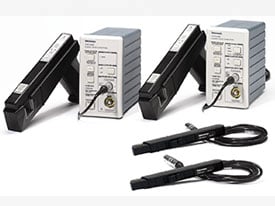
Tektronix Current Probes provide high sensitivity for accurate power and load analysis. Find the right Current Probe for your measurement needs.
quaint rivet
hearty karma
Sure there is: https://www.tek.com/en/products/oscilloscopes/oscilloscope-probe...
that still requires a destructive process of desoldering components
which could cause a lot of unwanted side effects
especially with capacitors
not fast and safe enough
ugh i hate our designer team, especially one of their "gifted" veterans
they're just too good, too good
just when you thought you've already obtained the measurement that you wanted
BAM, your load is too inductive, needs more resistance to get a more accurate reading on that IC
BAM, that conductor you're using to lift that capacitor is too long, shorten it a bit
@hearty karma is this how we really have to do our measurements? up to this tee?
hearty karma
No, doesn't require desoldering anything. The probe just clips around the lead and measures the current through it.
quaint rivet
hearty karma
No, doesn't require desoldering anything. The probe just clips around the lead ...
well what if the component is an smd diode or a throughhole capacitor with clipped leads?
hearty karma
And no, there are tons of ways to do measurements.
quaint rivet
well, how do you measure the current through smd components?
without any resistors attached to it?
@hearty karma how do you do this?
because most problems comes from smd diodes
and capacitors
because most of the time, those are the most difficult and important parts to assess
hearty karma
Those are tricker. The proper approach depends on the board itself.
quaint rivet
and the designers are really REALLY finicky if we do something wrong since it means extra work for them if our measurements ended up showing a failure, lol
hearty karma
That's because (as we have pointed out before) the designers have not done their jobs properly.
quaint rivet
ehhh, m8, problem is, it's not just our designers, we have to consult to other industry's designers as well
so like it's us vs them
hearty karma
Which (as we've also pointed out before) is a management problem. It seems like you do talk with designers (you say they become irate), so there's something here that I'm missing.
quaint rivet
hearty karma
Which (as we've also pointed out before) is a management problem. It seems like...
ugh, i can't tell you much without breaking some sort of nda im afraid
im walking on a tightrope here as well, i don't know how much i could actually share
but let's just say, there are things that we design and things that we source from, but everything goes through my division, the design quality assurance department
hearty karma
The whole broken procedure, third party suppliers, and "safety is paramount" pronouncement that's not backed by actual engineering all points to a company trying to shift blame to expendable people.
quaint rivet
eh, i wouldn't conclude it that way but, i guess
makes you wonder why my company has been up for so long
quaint rivet
hearty karma
The whole broken procedure, third party suppliers, and "safety is paramount" pro...
third world country standards i suppose
 icy moth
quaint rivet
third world country standards i suppose
icy moth
quaint rivet
third world country standards i suppose
Sourcing through overseas countries is interesting. You could end up with a place that does things pretty cheap but delivers ridiculously good quality, to places that are more expensive but have very little design/manufacturing controls, and a whole spectrum in between. All cheaper than you can manage to do in the US/most EU countries
It feels like a crapshoot
It’s honestly any wonder some people obsess about doing as much of the process themselves
(It’s me, I obsess about it lol..)
hearty karma
Shifting blame seems to be a popular practise in the US
quaint rivet
icy moth
It’s honestly any wonder some people obsess about doing as much of the process t...
Cant really focus on that, especially when you need to build a new factory for the product you're trying to sell
 regal horizon
hearty karma
Shifting blame seems to be a popular practise in the US
regal horizon
hearty karma
Shifting blame seems to be a popular practise in the US
That's not the US's fault it's a trait we brought over from early settlers. 😅
quaint rivet
yo, question, what's the best place to stick a thermocouple to when measuring the temperature of an LED, the casing, the soldered pads, or what?
 vital sparrow
regal horizon
That's not the US's fault it's a trait we brought over from early settlers. 😅
vital sparrow
regal horizon
That's not the US's fault it's a trait we brought over from early settlers. 😅
I'd say it's a future problem 🤷♂️
regal horizon
Eh it was meant to be a joke about deflecting. 😛
vital sparrow
I'm just deflecting also hehe USA! USA! Gooooo ducks
hearty karma
Presumably you want to measure the temperature of the die? Ideally you'd drill into the casing and situate the thermocouple directly below the die between the leads. However, in most cases that would not be practical, so on the casing or on the lead with the best thermal coupling (often the cathode) close to the casing.
quaint rivet
hearty karma
Presumably you want to measure the temperature of the die? Ideally you'd drill ...
sheesh how do you even do this with small smd LEDs?
as in drill in between the casing andd leads?
 rugged elbow
what's your goal, prevent overheating?
quaint rivet
rugged elbow
what's your goal, prevent overheating?
Just checking whether an led is not overheating according to our set limits
silver glacier

It's a diode. Given a constant current, you can simply measure the voltage drop across it.
The fact that thermocouples are inherently conductive is going to be problematic, plus the thermal mass of the probe would easily be enough to act as a heatsink for an LED die.
quaint rivet
silver glacier
It's a diode. Given a constant current, you can simply measure the voltage drop ...
Well we did do that until the higher up says "use an oscilloscope to be more detailed, a multimeter cant detect those hidden peaks and fluctuations"
silver glacier
The oscilloscope is not more accurate at DC measurements.
quaint rivet
silver glacier
The oscilloscope is *not* more accurate at DC measurements.
tell that to a veteran worker
what about in power electronics?
silver glacier
Depends on what you're measuring.
You cannot reliably measure microvolts with an oscilloscope.
quaint rivet
well then what could possibly can we see and measure using an oscilloscope?
i feel like this is only done to appease the designers
silver glacier
For what you are testing, probably nothing.
quaint rivet
then what could the lead want from oscilloscope testing?
silver glacier
Can't know that without knowing what the purpose of the board is.
silver glacier
Is there any reason this board should ever see transients?
quaint rivet
overheating due to over use?
not really transients but we just want to make sure the power dissipation is on spec
to the tee
silver glacier
Is this a switching power supply board?
quaint rivet
at least, that's what the designers want
quaint rivet
silver glacier
Is this a switching power supply board?
no but we do test chargers as well that requires oscilloscopes
i don't know okay, the designers want us to use oscilloscopes for possibly every semiconductors as of now
silver glacier
So... they're wanting you to validate their design without even knowing what the design is supposed to do?
quaint rivet
silver glacier
So... they're wanting you to validate their design without even knowing what the...
m8, they know what the design is supposed to do
im just not telling u because it relates to office works and prototypes
lol
silver glacier
Yeah I get that.
quaint rivet
im risking my employment over here
but even if i do tell you, they're still demanding us to use an oscilloscope to test for every signal based components such as diodes and capacitors
for every type of pcb that we receive
silver glacier
First, please don't risk your employment. Second, you can't just plug an oscilloscope into everything and expect to get useful measurements. This is especially true for power dissipation, where the scope probes will generally do more to interfere with the circuit than to measure anything of value.
But if they are expecting you to perform any kind of test on the design, they are going to need to tell you what the expected behavior is.
Without that information, you might as well be touching each component with your finger to see what is hot.
rugged elbow
If this is really important stuff that you need assistance with, maybe use a consulting firm and a NDA
quaint rivet
rugged elbow
If this is really important stuff that you need assistance with, maybe use a con...
all i need is a forum to discuss these stuff with because im really new to the world of QA
and electrical engineer
and so far, people tend to question me back rather than give me substantial leads
 worn ferry
Often that's because either more information is needed since there's no one size fits all solution to the problem, or the question/application inherently doesn't make sense.
Unfortunately, I have no input on the original question.
quaint rivet
man how do you even discuss these stuff with other workers irl?
 onyx marten
ask them
 idle solar
Has anybody made a portable serial monitor? What was the purpose?
 violet torrent
You probably could to monitor serial communication
vital sparrow
Does too much thermal paste on a CPU end up as an insulating barrier or will heat dissipate correctly even if a fraction or fractions more than recommended?
Or is it beneficial to be a little bit liberal with it
hearty karma
quaint rivet
but even if i do tell you, they're still demanding us to use an oscilloscope to ...
Most oscilloscopes are grounded, so if you connect a probe ground to a circuit node at voltage, you create a short circuit and damage stuff. Additionally, most scopes have limits to the voltages they can survive at their inputs, so mains voltage (and higher) circuits need the correct probes and techniques for safety (of both the operator - you, and the equipment)
hearty karma
vital sparrow
Does too much thermal paste on a CPU end up as an insulating barrier or will hea...
A fraction more is generally okay, but the thermal paste is not nearly as conductive as a metal-to-metal contact, so too much can impede heat transfer. The idea of paste is to fill small gaps, as it's a better heat conductor than air. This is why some people use liquid metal thermal compound, which is very conductive even in thick layers.
 fossil glen
vital sparrow
Does too much thermal paste on a CPU end up as an insulating barrier or will hea...
fossil glen
vital sparrow
Does too much thermal paste on a CPU end up as an insulating barrier or will hea...
You want the minimum amount of thermal past you can possibly get away with, and still have good thermal contact. TL;DR thermal paste has a higher thermal "resistance" than copper or aluminium, so the less of it involved, the better your heat transfer will be.
A trick I learned a loooonnggg time ago is to place four pieces of scotch tape right on the edges of the CPU top. Most of the scotch tape hangs over the edge, but the four pieces together still outline a square that covers almost all the top surface of the CPU. Then put the smallest bead of thermal paste on that you can, and use a credit card to spread it around so it completely covers the CPU top. Takes a bit of practice, but if you do it right, the scotch tape keeps the credit card just a fraction of a millimeter above the surface of the CPU, leaving a really thin film of paste.
Then peel off the scotch tape, apply the heatsink carefully, tighten it down and go to it.
quaint rivet
hearty karma
Most oscilloscopes are grounded, so if you connect a probe ground to a circuit n...
I wonder, are there any commercially available oscilloscopes that are not grounded? Our team circumvent around this by modding the plug if im not mistaken
hearty karma
There are battery powered ones. You can also use an isolation transformer to separate them from mains ground. In either case, you have to be careful about touching the chassis which can now float at various voltages. Cutting the ground pin off the plug is a dangerous approach and may violate various workplace safety rules.
quaint rivet
how do the professionals do it?
hearty karma
A variety of techniques, depending on the conditions. One approach is differential probes, which allows measuring a difference in voltage between two points, neither of which must be zero volts.
quaint rivet
hearty karma
A variety of techniques, depending on the conditions. One approach is different...
how to make it a permanent solution though?
hearty karma
How to make measuring something a permanent solution? Generally to do that, the board designer will include built-in test points. From the previous description, it seems like that option isn't available.
quaint rivet
oh no, i mean how to make a permanent ungrounded oscilloscope?
 amber zinc
Hi, relatively new here
Does anyone know how difficult it would be to use a feather to control a FONA board?
I'm trying to make a very simple cell phone that just calls and answers calls, no text, no screen, one button, hard coded phone line it's calling to
rugged elbow
quaint rivet
oh no, i mean how to make a permanent ungrounded oscilloscope?
use a differential measurement, or a battery powered oscilloscope
quaint rivet
rugged elbow
use a differential measurement, or a battery powered oscilloscope
i see
 main hemlock
amber zinc
Hi, relatively new here
Does anyone know how difficult it would be to use a fea...
main hemlock
amber zinc
Hi, relatively new here
Does anyone know how difficult it would be to use a fea...
these modules use obsolete standards (2G, 3G), that are being removed in most places. What country are you in?
that's why thye are mostly out of stock
hearty karma
amber zinc
Hi, relatively new here
Does anyone know how difficult it would be to use a fea...
It's easy to control a FONA board with a Feather, they use a simple asynchronous serial protocol and there's a library available. However, danh is right, there aren't many networks left that support those older protocols. There are more modern cellular modules available, but you'd need to do more work to talk to them. Not a lot more work, they use a more or less standard set of "AT" style commands. I'll point out that CircuitMess offers a simple cell phone kit.
hearty karma
The modules in the FONA boards are made by SIMcom, who did offer updated modules like the SIM7600, but SIMcom was acquired by u-blox a few years ago. They offer LTE Cat 4 modules like the LARA-L6004, which could be a possibility. Another possible vendor is Quectel, their EC25 module might do, and it's a lot cheaper than the LARA one. If you want one on a board like the FONA boards, I have used older versions of this one, it should work fine with a Feather if you wire it up properly (it only takes a few connections, as it's an asynchronous serial device like the FONA): https://www.mikroe.com/4g-lte-e-click

MIKROE
4G LTE click is an LTE Cat 1 / EGPRS multimode cellular network solution, featuring the compact LARA-R2 series modem from u-blox. MIKROE-2527
worn ferry
Man, all this talk of cellular modules, and I'm reminded of the person trying to claim that the Steam Deck couldn't have cellular unless they loaded it with a load of bloatware and got a contract with someone like AT&T or Verizon.
Like, no? That's literally not how cellular works.
hearty karma
They would have to get a contract with a carrier, but sending data over cellular isn't too tough.
worn ferry
The user would have to get a contract, sure. But the original person was suggesting that Valve would have to get a contract to get the device authorized in general.
I swear I know how cellular works. Somewhat. I just scramble my own thoughts sometimes.
silver glacier
If Valve were to integrate the cellular chipset directly onto their board it would require a bunch of extra FCC hoops, but if they use an off the shelf module only that module would need to have the extra stuff done.
worn ferry
Interesting. I didn't know the difference in FCC stuff. Is that why you tend to see a lot of wireless modules as little boards soldered onto the mainboard instead of just the components themselves?
The wireless module went through its own testing, so the laptop or whatever doesn't have to?
silver glacier
worn ferry
Interesting. I didn't know the difference in FCC stuff. Is that why you tend t...
Yes, because any change to the main board would trigger a long and expensive recertification in that case.
So it's much cheaper and easier to install a module.
worn ferry
Makes sense.
silver glacier
Phones and tablets of course lack space, so they are usually forced to put it onboard.
Everything else uses modules where possible though.
zinc burrow
another factor, a radio module certification, is only valid with a certain antenna
if you connect the wrong antenna to the module, it may violate the fcc regulations, and so the certification doesnt apply
worn ferry
I suppose I don't know enough about radio to know what could go wrong with the wrong antenna other than not being able to send/receive on the expected frequency.
zinc burrow
a directional antenna could focus the existing rf energy into a tighter beam
and then exceed the limits on rf energy density
worn ferry
Ah.
zinc burrow
same thing if its just a better antenna
more energy dumped into the same area
the latest iphone wasnt legal to sell in france, because it was going over the rf radiation limits for the country
and then every news outlet dropped the word rf from that
and began causing a panic about nuclear phones 😛
worn ferry
Of course.
zinc burrow
you know that screen your looking at? its bombarding your retina with radiation!!! 😄
even an e-ink screen is!, its just reflected radiation!
worn ferry
The funny thing is that, if I'm correct, light is a much higher energy than cell phones anyway.
silver glacier
It can also have safety implications, if the wrong antenna it may resonate at subharmonics of the operating frequency that could end up interfering with something important like emergency channels or air traffic control.
silver glacier
worn ferry
The funny thing is that, if I'm correct, light is a much higher energy than cell...
It's all about energy density.
i.e. How much energy is in a particular area?
worn ferry
Right, obviously a very dim light is less powerful than a powerful transmitter.
zinc burrow
silver glacier
It's all about energy *density*.
https://www.youtube.com/watch?v=W6FbUiiwutQ
how does 100W CW in a laser sound? 😄

Install Raid for Free ✅ IOS: https://clcr.me/wN6teZ ✅ ANDROID: https://clcr.me/J8OJjV ✅ PC: https://clcr.me/cRzay3 and get a special starter pack 💥Available only for the next 30 days
I built the world's most powerful handheld laser! The output power is over 100W, which is literally insane.
Social media ...
silver glacier
worn ferry
Right, obviously a very dim light is less powerful than a powerful transmitter.
You can wear Bluetooth headphones all day without any issues, but you wouldn't want to stick your head inside a running microwave.
worn ferry
Give you a pretty good buzz though.
zinc burrow
skip to ~10mins in, to see the beam at full power
the beam sets fire to his desk, in under 5 seconds
and a paper bag, basically just ignites instantly
icy moth
silver glacier
It's all about energy *density*.
My energy density is close to 0 😬
zinc burrow
but, you can get far far greater energy densities, if you use a pulsed laser

This laser tattoo removal device from eBay is the most powerful laser I've shown on this channel! It is so powerful that even AIR ignites in the laser beam!
Social media sillyness:
instagram: https://www.instagram.com/styro.drake
shorts channel: https://www.youtube.com/c/styropyroshorts
patreon: https://www.patreon.com/styropyro
backup channe...
icy moth
At this point, why not just build a Death Star
zinc burrow
this thing can melt titanium
worn ferry
Lots a watts, tiny run time.
zinc burrow
lots of math on the energy density ~10mins in
icy moth
Lots of calculus
worn ferry
I've had tattoo removal done. I actually asked what happens if they target a spot that doesn't have any ink.
Basically? Nothing. The laser is tuned specifically to react to the inks in tattoos. If you use it on untattooed skin, it basically does nothing.
icy moth
Who doesn’t love calculus
zinc burrow
worn ferry
I've had tattoo removal done. I actually asked what happens if they target a sp...
but as styro demod, that kinda only works well on light colored skin
worn ferry
Yeah. Darker skin is going to do what darker objects do in general with light.
Absorb a lot more of it.
silver glacier
icy moth
My energy density is close to 0 😬
zinc burrow
 worn ferry
Heh
zinc burrow
 worn ferry
Joke would be on him if he were my cat.
I'm a heavy sleeper and wouldn't even notice.
zinc burrow
ive seen another one, where the cat figured out, wake up the toddler
his cries will wake the adults
worn ferry
I get to sleep knowing that the kid isn't mine (bought a house with a friend and his wife, and they have two kids.)
I'm totally detuned to that. My friend once asked if his son crying at night ever woke me up. "He cries at night? News to me."

 zinc burrow
silver glacier
https://tenor.com/view/captain-america-marvel-avengers-gif-14328153
zinc burrow
silver glacier
https://tenor.com/view/captain-america-marvel-avengers-gif-14328153
yeah, i wasnt sure after posting it
but you didnt say anything (for about 3h), so i thought it was fine
silver glacier
- I'm not a mod.
- Distracted by

zinc burrow
lol
worn ferry
My counter project continues. I now have a whole TWO devices on my SPI bus. Which is pretty good because I'm driving it without the help of libraries.
Libraries actually wouldn't be usable since I don't have enough pins for the display's reset and D/C pins anyway.
quaint rivet
so guys, what do you use to stick thermocouples?
we currently use heat insulating tape but it's not really that sticky
silver glacier
You could probably use some type of epoxy, but it really depends on what you want to stick it to.
quaint rivet
silver glacier
You could probably use some type of epoxy, but it really depends on what you wan...
what about capacitors?
also, what kind of epoxy are you talking about?
silver glacier
quaint rivet
what about capacitors?
What does that have to do with thermocouples?
quaint rivet
silver glacier
What does that have to do with thermocouples?
i want to stick thermocouples to capacitors
what should i use?
silver glacier
quaint rivet
also, what kind of epoxy are you talking about?
Just general purpose epoxy, usually silicone-based.
quaint rivet
ah so those squishy sealant things?
silver glacier
There are also more specialized thermally conductive epoxies, but I don't know any specific brands.
silver glacier
quaint rivet
ah so those squishy sealant things?
Yeah pretty much.
hearty karma
Blu-tac (if it's cold), hot glue (if it's warm), silicone (if it's hot)
quaint rivet
you guys got any cheap alternatives for silicone?
we only have those for sealing stuff that comes in big cans
are there like specialized ones for sticking stuff?
silver glacier
For a test fixture price shouldn't matter too much.
silver glacier
Normally you wouldn't be putting adhesive on a temporary fixture.
One other thing worth emphasizing: capacitors should not be heating up significantly under normal operation. If they are, there's a design issue. Usually something like exceeding ripple current ratings.
For your use case though a FLIR or similar IR camera would be more appropriate.
That is by far the most common approach when debugging a board that overheats.
 red anvil
Hello. Im trying to get the 64x128 monochrome OLED to work with my ESP32 Feather v2. I have it connected over STEMMA QT and it says its getting power but I cant seem to get anything on the display
 pseudo zinc
red anvil
Hello. Im trying to get the 64x128 monochrome OLED to work with my ESP32 Feather...
pseudo zinc
red anvil
Hello. Im trying to get the 64x128 monochrome OLED to work with my ESP32 Feather...
What programming language are you using with your Feather?
red anvil
C++ in the arduino IDE
hearty karma
It's supposed to be an X-wing. Kinda?
 pseudo zinc
I'd recommend asking in #help-with-arduino - I'd also share your code, see #welcome on how to post code if you need to
red anvil
Okay ill repost there
quaint rivet
silver glacier
For your use case though a FLIR or similar IR camera would be more appropriate.
IR cameras aren't really that accurate in my experience
silver glacier
Ratiometric ones are. Also, how accurate does it actually need to be? Thermocouples are only going to get you within a few degrees celsius, and epoxy isn't going to improve that figure.
quaint rivet
how accurate does it actually need to be
since we don't always have our big testing equipment available to us, any 1 or 2 degrees offset determines whether a component passes our test or not
simply put, we're a new division
yeah, that's an info that i should've disclosed i guess
hearty karma
Just get temperature crayons?
quaint rivet
oooh what's that?
quaint rivet
silver glacier
Ratiometric ones are. Also, how accurate does it actually *need* to be? Thermoco...
can you tell me which epoxy adhesives you use to stick thermocouples? it would quicken our setup processes
silver glacier
I don't have to do it personally, so nope.
1-2°C is not going to make a significant difference in the short term. It might be able to reduce the long term component life though.
quaint rivet

Learn how to attach Datapaq PA0210 thermocouples to a circuit board using adhesive.
Learn more: https://www.flukeprocessinstruments.com/
Request more information: https://www.flukeprocessinstruments.com/en-us/sales-support/where-to-buy-temperature-profiling-solutions
Facebook: https://www.facebook.com/FlukeProcessInstrumentsAMS/
Twitter: http...
what about the red stuff in this video, what could possibly be the adhesive that's being used?
Looking up "thermocouple adhesive" or "high temp adhesive" either brings mechanical sealants or expensive products
silver glacier
And, like I said earlier, capacitors shouldn't really be heating up much if they are being operated in-spec. Resistors and inductors can get pretty toasty due to their series resistance, but the ESR of a cap will generally be much smaller.
quaint rivet
that doesn't change the fact that we need to do measurements sooooo
yeah, still need some names and leads
hearty karma
Could be Glyptal
silver glacier
quaint rivet
Looking up "thermocouple adhesive" or "high temp adhesive" either brings mechani...
I suppose you could try using silicone RTD paste.
hearty karma
Could be Loctite 384
Or 567, or 315. https://www.researchgate.net/publication/347732370_Study_of_Temperature_Measurement_Accuracy_by_Using_Different_Mounting_Adhesives
ResearchGate
PDF | Thermal compounds are adhesive used to improve heat conduction between two surfaces. It can be used to secure a thermocouple to a surface which... | Find, read and cite all the research you need on ResearchGate
quaint rivet
ooof loctite, aren't they super glue and for threads?
silver glacier
Loctite makes a variety of adhesives.
But they are best known for their thread glue.
 inner linden
I guess when it comes to glue brands, they have a lot of adherents.
silver glacier
inner linden
I guess when it comes to glue brands, they have a lot of adherents.
Poor cohesion
onyx marten
u'all are just stuck on this subject
quaint rivet
onyx marten
u'all are just stuck on this subject
do you know any good quick acting adhesives for thermocouples?
onyx marten
but i guess it is cement-tically correct
quaint rivet
working in a third world country in asia really dwindles down my options when it comes to products from abroad
onyx marten
no, sorry dude - just bad jokes
quaint rivet
lol
inner linden
I try to only be so helpful that nobody ever tries to upgrade me beyond master punster status.
icy moth
quaint rivet
do you know any good quick acting adhesives for thermocouples?
It’s only good to like 150°C though

Choose from our selection of thermocouple adhesives in a wide range of styles and sizes. In stock and ready to ship.
McMaster has a whole page for thermocouple adhesives too
Wow, so many options too
I’m gonna have to save that page for later.
inner linden
A nice lady who is a friend-of-a-friend dropped off a giant metal monstrosity that needs electronics in my living room and she was complaining about not having the right screws from the local hardware store and I instantly said "Oh, have I introduced you to our lord and savior, McMaster Carr?"
idle solar
Has anyone used the u8g2 oled library for a standalone AVR microcontroller? Specifically for ATMega328P-U
rugged elbow
McMaster Carr is about 15 minutes down the road, so if we put in an order in the morning, they'll deliver that afternoon, or we can run and pick it up. It's amazing.
hearty karma
That's handy! Maybe I should move to Thief River Falls (home of DigiKey). I wonder if they're hiring...
 proper escarp
rugged elbow
McMaster Carr is about 15 minutes down the road, so if we put in an order in the...
proper escarp
rugged elbow
McMaster Carr is about 15 minutes down the road, so if we put in an order in the...
I live about 100 miles form them, but they typically deliver next day
icy moth
hearty karma
That's handy! Maybe I should move to Thief River Falls (home of DigiKey). I wo...
I’m guessing they probably are because my last two orders from them have been delayed
silver glacier
rugged elbow
McMaster Carr is about 15 minutes down the road, so if we put in an order in the...
So they still charge like $20 for shipping?
worn ferry
icy moth
I’m guessing they probably are because my last two orders from them have been de...
You too? I ordered some IO expanders, and it was like 5 days between when they claimed they shipped them to when FedEx actually got them.
icy moth
I’m just wondering what’s going on because I’ve rarely had orders delayed
hearty karma
I've given up on FedEx. My last order was shipped promptly.
inner linden
I was not doing nearly enough electronics or biking when I lived within biking distance of Jameco.
worn ferry
At this point I don't even remember what spurred my current interest in making my own electronics. Which is interesting because it wasn't that long ago. I just know this is like the third time I've gotten into it.
First time I expressed an interest in this kind of thing, my dad got me an Arduino starter kit for Christmas. Not much came of that. Then I backed the DigiSpark kickstarter because I thought it was neat. Nothing came of that. Now I'm doing a whole bunch of stuff, and have even gotten a custom board.
silver glacier
I accidentally broke a mercury vapor rectifier in a tube tester given to me by my grandpa. The next day, I decided I wanted to go into electronics engineering...
(true story)
worn ferry
Heh.
The nice thing is that it took ages, but the original Arduino starter kit has not gone to waste. It's currently my ATTiny programmer.
onyx marten
inner linden
I was not doing nearly enough electronics or biking when I lived within biking d...
altech electronics for me (in Austin) and then Frye's before they went too consumer (and died)
onyx marten
worn ferry
First time I expressed an interest in this kind of thing, my dad got me an Ardui...
this is the mumbledy-mumble time for me (my first was a crystal diode radio way back in the dark ages) -- i'm more interested in "systems" so the recent big expansion into I2C components is making me deliriously happy
inner linden
I had wanted to get into electronics and get an EE degree and all but ended up with a Math/CS degree instead which is proooobably fine for me. But I'd always liked to screw around with stuff. A lot of things happened when I realized that there was my one chance in life to learn how to bend neon which led to a whole bunch of different artistic directions but not necessarily a whole lot of electronics. But one birthday, a friend whose husband worked at one of the LED manufacturers gave me some random bits from the lab. And... yeah, so if someone shows up to your birthday party with some random bits from her husband's lab, that's normally grounds for never being invited over ever again, right? But that ended up with me having one LED sampler board with the whole spectrum from red to blue that worked perfectly for my long-exposure photography hobby which was fine, except that one day the battery wires was loose and so I realized that it wasn't good for me to rely on a single thing with no replacements, so that's when I ended up with a component hoard and taught myself all the things.
I guess folks don't realize how much toil there was in AVR development for people who just want to play with systems before the Arduino environment came along.
Thankfully my AVR STK500 didn't go to waste. It's currently my custom-Arduino bootloader installer.
worn ferry
Yeah, the fact that someone like me can just order a few random bits and bobs, download a free development environment, and then build their own hardware is just something that cannot be overstated how amazing it is. We have it easy on a staggeringly large number of fronts.
My current project will hopefully eventually see the use of a boost circuit.
But I don't know the specifics of what support components I need.
No biggie. TI has a whole power circuit designer on their site. Put in your input voltage range, output target, current requirements, and it'll spit out a full schematic and parts list for you.
regal horizon
inner linden
I had wanted to get into electronics and get an EE degree and all but ended up w...
Guess you could say you pictured the future.
idle solar
May someone guide me on what people have done to approach debugging code in the MCUs? I know it may differ depending on what they are working with.
I'm always used to the luxury of setting breakpoints with text editors or IDEs strictly on the software side of things.
for me, I'm using an AVR chip. I've heard Atmel Studio has a feature that emulates a microcontroller. Though I don't use Windows so I had use avr-libc. For that I saw simavr and avr-gdb, but I'd like to have people's opinions on it from their experience.
worn ferry
Since I do most of my stuff through the Arduino IDE I generally take to adding a ton of Serial.print commands to track variables or program progression.
Obviously this won't work (easily) when I'm targeting the ATTiny or other chip that doesn't have native serial over USB, but in cases like that I generally start with getting it working on something like the Trinket M0 which does have serial over USB. The assumption being that as long as the logic is sound on the M0, and it compiles for the Tiny, I'm good to go.
This is not always the case as I found out though. That was a learning experience though.
 pine igloo
I can’t find which is ground
 worn ferry
Best guess? White. See if you can use a multimeter (assuming it's safe to do so) to find which one connects to the ground plane of the board.
What is it anyway?
summer dagger
How many parallel tasks can I run on a esp32 adafruit feather v2?
worn ferry
The first question I would ask is "how are any of those descriptors wrong?"
The time of flight sensor fires a pulse of light out, and measures the time it takes to return (the time it was in flight). So, how is it not a time of flight sensor? Yes, LIDAR does the same thing, but how is time of flight wrong?
Is the proximity and light sensor not measuring how close an object is (ie, it's proximity to the sensor), or how bright the ambient light is? Etc.
There can be multiple names for a single item. None of those names are wrong for those products.
rugged elbow
silver glacier
So they still charge like $20 for shipping?
It's usually closer to $10, and it's some guy in a truck doing a local route
pine igloo
worn ferry
What is it anyway?
It’s a thrustmaster tca airbus sidestick
A flight joystick


The inside of the handle
It controls the buttons and triggers on the handle in pretty sure
Thrustmaster support won’t let me have the wiring schematic
Oof
quaint rivet
guys, do we need a diode to drive a dc relay?
pine igloo
pine igloo
Thrustmaster support won’t let me have the wiring schematic
That's typical for consumer stuff. They're also cheaper as they can be
What are you doing anyway?
To find gnd as you were told you can use a meter
 unborn pasture
I'm considering buying some sort of IR camera for detecting hot components and trying to repair pcb's. I'm assuming the ones that connect to a phone are the cheapest bet but I'm still looking at a £100-300 investment which is quite a bit. Anyone got advice on the sort of sensor i should look for. Would 32*32 pixels suffice?
 robust rampart
I was wondering if there is anyone that could help me get some neopixels working. I have a bluefruit circuit playground and a strip of neopixel dots. I followed the guide and got Circuitpy loaded on the board, but once sending code to the lights nothing happens.
 pallid orchid
unborn pasture
I'm considering buying some sort of IR camera for detecting hot components and t...
pallid orchid
unborn pasture
I'm considering buying some sort of IR camera for detecting hot components and t...
would a flir lepton3 meet your need?
robust rampart
I was thinking maybe it was because I had to load CircuitPython 8.1 instead of the latest 8.2 (the guide said unless i update the bootloader I can't run 8.2)
Now the Bluefruit is flashing red 2x quickly
unborn pasture
pallid orchid
would a flir lepton3 meet your need?
Probably. That's the sensor specifically right? I'm looking for an all in one solution so should I look for ones that have that sensor listed
pseudo zinc
robust rampart
I was thinking maybe it was because I had to load CircuitPython 8.1 instead of t...
I would recommend asking in #help-with-circuitpython - cross-posting is usually discouraged, but in this case I would recommend it. You will probably have better luck there. We're almost all volunteers, so if someone knows, they'll usually speak up when they are around.
pallid orchid
unborn pasture
Probably. That's the sensor specifically right? I'm looking for an all in one so...
i think so, unless you're referring to the microbolometer which is out of my knowledge, the lepton is just the camera and lens, which you would attach to a breakout board
rugged elbow
Lepton + PureThermal board gives you an easy thermal USB camera for a laptop
works well with Python too
hearty karma
quaint rivet
guys, do we need a diode to drive a dc relay?
It depends somewhat on what you're driving it with, but in most cases, you'll want a protection diode.

 cobalt swan
What’s your goal with it? Still the Marauder?
 regal tartan
So I'm using this circuit to make an audio amp, and I see that it's asking for a 100nF capacitor. I assume that means ceramic because all the non-ceramic capacitors are microfarads, not nanofarads.

However, this box of ceramic capacitors I have doesn't actually label by nF, and instead it uses some random numbers like 2P, 10P, 82P, 332, etc.
Also, why do the electrolyte capacitors have direction indicators, while the nF one doesn't
Do ceramic capacitors not have a direction?
Oh wait nevermind, apparently this one was labeled 100nf as 104
So now the audio amp technically "works" but boy does it sound terrible
hearty karma
You can use a ceramic or film capacitor for a low value like that. And yes, ceramic and film capacitors are not polarized like electrolytics. The "10P" type markings are presumably picofarads. The 3-digit markings work like resistor color codes, so 332 is 33 ⨉ 10², or 3300 picofarads, which is 3.3 nanofarads.
Yeah, 104 is 100nF
regal tartan
I can hear my audio over the speaker, but it also sounds like the microphone is inside an elephant's stomach and I'm also hearing digestive sounds
hearty karma
It could be a biasing issue, the amplifier generally can accept signals between its positive and negative supplies. However, many audio signals are centered on zero volts and go to both negative and positive voltages. You may need coupling capacitors and a bias network on the input side.
regal tartan
Oh lol I had the ground of the speaker plugged into 5V
Now there's still some popping but definitely less noisy
It's also a lot quieter though
hearty karma
That could have something to do with it
regal tartan
Now ironically I need to figure out how to boost it further
I should also mention I'm playing the audio from an SD card via a nano
hearty karma
You can connect a capacitor from pin 1 to pin 8 to boost the gain
regal tartan
Just another 16V 100uF?
hearty karma
10µF is probably enough. Positive end goes to pin 8.
Actually I'm not sure which pin the positive side goes to, references seem contradictory
I just pulled up the TI data sheet, which shows the positive end to pin 1. 🤷🏾
inner linden
We all benefit from an un-biased opinion here.
regal tartan
Holy macaroni
So I put a capacitor between pins 1 and 8, 22uF, and it removed almost all the noise
But it didn't really boost it
hearty karma
That's bizarre.
regal tartan
Like let me grab a video the difference is wild
Sorry my hands are super shaky
Like the clicking instantly goes away when the capacitor is plugged in
I'm powering the thing using a 12V battery pack brought down to 5V, and if the SD card module could take it, I'd just use the 12V directly.
regal tartan
Actually, it's like the LM386 is doing nothing
Because when I plug the speaker directly into the arduino pin that's outputting audio, the volume is the exact same
worn ferry
Ok, so I think your first problem is that you're powering everything from 5V. You're not going to get any kind of amplification if your SD module is already generating a 5V peak signal and your amp is also only powered by 5V.
I get the feeling that you're going to need to generate two supply voltages for this to work. 5V for your SD module, and then something higher for the amplifier. Depending on which specific LM386 you have, it will accept a supply voltage up to either 12 or 18V. So conceivably you can run the SD module off your 5V supply, and put the LM386 straight on the 12V
regal tartan
Alright, I just finished soldering an old USB cable to some solid core wire, and I have a portable charger that I can plug that into for my 5V supply
Then use the 12V for the amp, let me try it
regal tartan
worn ferry
I get the feeling that you're going to need to generate two supply voltages for ...
Do you think the nano would work with 13V going into it?
worn ferry
My first thought, no. Absolutely not. But let me see if I can dig up a datasheet.
regal tartan
Okay, cause my 12V power supply is 8x AA batteries which are like 1.8V each so it's about 13.6V
I guess I can just run the nano off the same 5V from the portable charger though, and then I should be good to go
worn ferry
Input voltage for the Nano is apparently 7-12V.
So, it will likely survive 13.6V, but the regulator is going to be rather unhappy about it. I wouldn't suggest it.
Oh, and I should point out that even if you supply 12V to the Nano, it's still only going to operate at 5V
regal tartan
Okay
So I got the LM386 moved over to 12V
And the SD card and nano running off 5V
However, the volume is still super quiet
It's a little louder
Luckily there's now actually a volume different when I unplug the gain capacitor
worn ferry
So that's the next thing. It looks like you're using a polarized capacitor for the gain setting, when all the references to it in the datasheet shows it as an unpolarized one.
Unfortunately, I don't know how the gain is supposed to be set. Just that it "defaults to 20 without any extra components" and "can be set between 20-200"
There is one schematic that shows it with the gain set to 50, and for that they put a 10uF cap plus a 1.2k resistor between pins 1 and 8.
Oh, here we go. Section 9.2.1.2.1 Gain Control on page 10.
 regal tartan
So what's the difference between a polarized and unpolarized capacitor?
Cause the gain is definitely NOT 200
 urban lintel
cobalt swan
What’s your goal with it? Still the Marauder?
urban lintel
cobalt swan
What’s your goal with it? Still the Marauder?
Yep!
hearty karma
regal tartan
So what's the difference between a polarized and unpolarized capacitor?
Electrolytic capacitors are polarized as a side effect of the way they work.
idle solar
Does anyone have an approach on implementing a menu in C on a OLED display? I'm using a ATMega328P-U.
hearty karma
idle solar
Does anyone have an approach on implementing a menu in C on a OLED display? I'm ...
The type of display shouldn't matter too much. There's a blog entry here: https://softsolder.com/2015/01/16/kenmore-158-ui-automatic-button-builder/
I’d rather not draw that detail by hand for each button
idle solar
hearty karma
The type of display shouldn't matter too much. There's a blog entry here: http...
Thanks, will look into this once I get back.
quaint rivet
Guys, question, do you guys know of any power resistors that are other than the big green ring clamp ones?
proper escarp
depends on what power you need.
I have used chassis-mounted resistors like this one
https://www.digikey.com/short/vq2qd3t2

Digi-Key Electronics
Order today, ships today. KAL50FB10R0 – 10 Ohms ±1% 50W Wirewound Chassis Mount Resistor from Stackpole Electronics Inc. Pricing and Availability on millions of electronic components from Digi-Key Electronics.
regal horizon
big green ring clamp? do you mean a ferrite choke?
hearty karma
I'm thinking the "big green clamp" ones referred to are vitreous adjustable resistors like these

There are non-adjustable versions as well (like the classic "brown devil" and broomstick style ones), and smaller ones like sandstone power resistors, as well as the aluminum cased ones shurik pointed out.
regal horizon
I've never seen one of those before, neat.
inner linden
I guess you just got ohm'd.
idle solar
Can software serial (UART) communicate (RX) with hardware UART (TX)?
The ATTiny85 doesn't seem to have hardware serial but can be implemented in software, while the ATMega328P has.
I'm using the ATTiny85 with the Arduino IDE. I like to use software serial to have it only listen to the ATMega's TX.
I am not sure if there will be difficulties ahead. I understand that Arduino is a variant of C++ which can be compiled down to C, which I am using to program the ATMega.
I've heard how the ATTiny is clocked can affect the Baud rate?
(ATTiny85 at internal 8MHz | ATmega328P at external 16 MHz)
Sorry for the dumb questions, I am in new territory.
silver glacier
Yes it can, but be aware that you won't be able to do much else SoftwareSerial running.
idle solar
silver glacier
Yes it can, but be aware that you won't be able to do much else SoftwareSerial r...
As in different Baud rates?
silver glacier
You have to set them both to the same baud.
idle solar
Would I have to go for a 16MHz crystal for the ATTiny then?
silver glacier
Not necessarily, since it probably uses the internal 16-bit counter to generate the baud rate.
Just be aware that you won't be able to run at a particularly high baud because SoftwareSerial will have significantly more jitter.
idle solar
Thanks for the tip, I'll experiment with this a little more.
silver glacier
I would maybe try 9600 baud maximum.
idle solar
That's what I have seen these sites use actually: http://www.technoblogy.com/show?TV4
http://www.rjhcoding.com/avrc-uart.php
worn ferry
Calls itself a "universal" serial interface.
Can't do basic serial. Ha!
Though I'm just happy that someone went and made libraries for SPI and I2C on the ATTiny chips.
My current project wouldn't be possible without the SPI one.
Though, actually I've only verified that it compiles for the Tiny. Not that it actually works.
 zealous ember
worn ferry
Calls itself a "universal" serial interface.
Can't do basic serial. Ha!
Though ...
zealous ember
worn ferry
Calls itself a "universal" serial interface.
Can't do basic serial. Ha!
Though ...
Isn't the thing that the ATTiny doesn't have USB and it's just some cursed bitbanged thing?
worn ferry
The ATTiny chips have USI, Universal Serial Interface. It's not USB, no, but it is capable of I2C and ISP, though not with the standard Arduino libraries.
zealous ember
ah lol 😆
worn ferry
Sorry, SPI, not ISP. Though it is programmable via ISP
Well, some of them are. Others use UDPI.
silver glacier
worn ferry
The ATTiny chips have USI, Universal Serial Interface. It's not USB, no, but it...
ISP generally utilizes the SPI interface.
worn ferry
Which is fun, because you could make an interface where you plug a peripheral into the ISP header when not programming.
Well, aside from the fact that you'd have to use the reset pin as an IO, and that would require that you use high voltage programming at that point.
zealous ember
high voltage programming?
worn ferry
I haven't looked at the specifics of it, but from what I understand once you set the reset pin to work as a standard IO, the only way to program the chip again is by first hitting it with something like 12V in a specific way. Note that the chip normally only works on up to 5V
zealous ember
🤯 wow sounds kinda cursed
but I suppose there have to be at least some weird things with such a tiny mcu
silver glacier
A lot of Atmel chips support it.
worn ferry
Ok, so a quick look at it, it seems like all that really happens is that the reset pin gets driven with 12v instead of bring brought to ground to get into high voltage mode. Everything else still runs on the standard 5v.
The main reasons one might need this kind of thing are wanting that one extra IO pin, or accidentally setting the chip wrong. Like if you set an external clock source, but don't have the needed clock.
silver glacier
Yeah, it's a biasing thing done to override fuses I believe.
worn ferry
Side note, I'm also happy that it's easy to make your own ISP using a different Arduino board.
When I was thinking about trying to program microcontrollers on their own, I was annoyed that all the programmers were like $50+
Then I found out you can make one out of an Arudino Uno, which I happened to have on hand.
Even better, when I decide to change over to a chip that uses UDPI, I can reuse the same board.
 cold prism
these wouldn't support using while charging, would they? https://www.adafruit.com/product/4410

Oh so handy, this little lipo charger is so small and easy to use you can keep it on your desk or mount it easily into any project! Simply plug it via any USB C cable into a USB port and a ...
worn ferry
Given that it's basically the same charger used in their feather boards, just on its own, I don't see why you couldn't use your project while charging it.
Depending on how much current you're drawing, you may see one of three cases.
If you're drawing more than the charger is set for, you'll drain the battery anyway.
If you're drawing less than I think 10% of the max charge current, you'll see it repeatedly topping off the battery.
If you're drawing somewhere between those two levels the battery will never finish charging since it will reach an equilibrium where the charger is effectively driving your project directly.
idle solar
Do Atmel's MCU share the same PortX, DRRx variable definitions? I was able to use the sample code (http://www.technoblogy.com/show?TV4) to an extent but wasn't getting expected results. I did not know what was going on the ATTiny's side so I'd want to create a minimal example and expand on that.
silver glacier
idle solar
Do Atmel's MCU share the same PortX, DRRx variable definitions? I was able to us...
They are fairly consistent, but not always identical.
The number of ports, physical pin locations, and alternate functions can vary between chips.
idle solar
silver glacier
They are fairly consistent, but not always identical.
Thank you, I've opted to use an sample code for the time being as the serial monitor portion of my project isn't the main focus.
Though I'd like to ask, is it possible to have a microsd interface with the ATMega328P to read its contents?
silver glacier
You can communicate with it using SPI, which is the 'fallback' interface. Note that you will probably need to have logic level translation (in both directions) unless you are running it at 3.3V, and that (micro)SD cards aren't always the most reliable when connected on a breakout board.
idle solar
I'm powering it with 3.3V. I've also happen to see this https://www.obdev.at/products/vusb/index.html. Not sure what to make of it as of yet but applying this as a Human Interface Device (HID) could be feasible?
silver glacier
Not entirely sure why you would want to use that instead of just getting a 32u4, but interesting.
idle solar
I just used whatever I had at the moment. The 32u4 is preferable in this case?
silver glacier
Yes, because it has USB support in hardware.
idle solar
Right, that reminds me. I've seen a video using the 32u4 with USB. It also mentioned the using software will cause a lot CPU load that'll only focus on that specific task.
silver glacier
Pretty much, yeah.
AVR has great instruction throughput for an 8-bit architecture, but it's still an 8-bit architecture.
It's very good at servicing interrupts quickly and doesn't have the massive inefficiencies of something like 8051, but it's no ARM core.
idle solar
Appreciate the advice, will take note on that.
 lean stone
i think the 12V "high voltage programming" protocol has its origins in older types of programmable memory chips, which required that higher voltage to program the memory cells. i think modern MCUs and memory chips have built-in charge pumps, so don't require an external 12V source for programming, but it's still useful as an exceptional signal to override protections
half hollow
The key here is that charge pump requires a clock to operate, so without the clock you need high voltage to program it.
zealous ember
oh, interesting!
silver glacier
lean stone
i think the 12V "high voltage programming" protocol has its origins in older typ...

 rough crypt
finally got a working prototype after a long time


just finished printing the case
now i just need to buy a battery and a charge circuit
 gritty acorn
hi
i need an help
when i use the l293d motor driver shield with the ultrasonic sensor the speed of the motor decreases
if i delete the code of the ultrasonic sensor the motor run at full speed
 glad fable
*** ADVERTISEMENT ***
THIS IS AN OFFER FOR PAID HELP WITH A PROJECT
FROM LEE ATKINSON OF MEANSTRIDE TECHNOLOGY, INC AND NOT AFFILIATED WITH ADAFRUIT.
WE SEEK A CODE REVIEW FOR A LARGE EMBEDDED IOT PROJECT WHICH USES CIRCUITPYTHON AND AN RP2040.
THOSE QUALIFIED AND INTERESTED SHOULD VISIT
https://meanstridetech.com/look-down-sensor-iot-code-review/
 lament crest
Heya, is there a way to turn a peripheral (say a potentiometer) so that it works with i2c?
violet torrent
you'd need to add a way to read the pot and send and receive i2c, which is entirely possible, I'd say either with a ADC, or a microcontroller, and Adafruit have a i2c peripheral that's basically what you'd want there
for either one
 cold pebble
for digital there are choices of GPIO expanders that are i2c
violet torrent
seesaw could be an option too
onyx marten
a rotary encoder like https://www.adafruit.com/product/4991 would work as well -- it's got the seesaw built right in and there's a lot of different register values to be read to approximate a pot
Rotary encoders are soooo much fun! Twist em this way, then twist them that way. Unlike potentiometers, they go all the way around and often have little detents for tactile feedback. But, if ...
regal tartan
glad fable
*** ADVERTISEMENT ***
THIS IS AN OFFER FOR PAID HELP WITH A PROJECT
FROM LEE ATK...

Short term job with a non-comete sounds like a lovely combo
Does that mean 7+ years with both Python and C++?
hearty karma
Like most job listings, the wording is generally not exact, just intending to indicate a level of experience. I would normally interpret it as 7+ years total, so a few years each would likely be sufficient.
Amusingly, I'm currently doing code review for a project that has some IoT components, but it's going to be open-sourced after early testing.
glad fable
hearty karma
Like most job listings, the wording is generally not exact, just intending to in...
Yes. 7+ Total. Wold be nice to have had formal code experience. Thanks Guys!
 hollow rover
rough crypt
finally got a working prototype after a long time
hollow rover
rough crypt
finally got a working prototype after a long time
What is it?
rough crypt
hollow rover
What is it?
i have a thing where i try and make expensive devices for as cheap as i can
that is a flipper zero
or will be
once i've written the code
i did a USB rubber ducky
too
out of a pico w
which is better than the ducky
casue remote execution
idk i just like the idea of making something expensive for really cheap
idle solar
Has anyone used SparkFun's OpenLog module? Also, does anyknow know how to debug an ATMega328P with simavr? I'd like to have some form of on-chip debugging.
lean stone
i thought simavr was purely a simulator? i have done on-chip debugging of an ATmega328P with DebugWire, but that’s a proprietary one-wire protocol that needs some specialized debug probes. (it’s been at least partially reverse engineered)
idle solar
I believe you're correct. My lack of knowledge confused the two. I just saw a video about DebugWire, will look in it.
silver glacier
lean stone
i thought `simavr` was purely a simulator? i have done on-chip debugging of an A...
My understanding is that blackmagicprobe has gotten quite good.
lean stone
silver glacier
My understanding is that blackmagicprobe has gotten quite good.
i have one, and it’s great, but it doesn’t support DebugWire (or even AVR) last i checked
 mystic quest
I ordered one of these to add to my pi 5 hat stack, this will go on the bottom of the stack and it make 3 hats with possibility of stacking more
https://pineberrypi.com/products/hat-top-2230-2240-for-rpi5

Pineberry Pi
Introducing the HatDrive! TM1S (TOP) - the ultimate companion for your Raspberry Pi 5 designed to enhance your experience with fast and reliable NVMe storage. We think that it is is a must-have for anyone looking to get the most out of their Raspberry Pi 5. 🚀💻 Key Features and Strengths: Specially Designed for Raspber
I want it to look redicilous yet be pretty nice
mystic quest
i know there are some differences with the way pi 5 handles gpio, will this work with the pi 5? https://www.adafruit.com/product/2340
This touch-able add on HAT for Raspberry Pi will inspire your next interactive project with 12 capacitive touch sensors. Capacitive touch sensing works by detecting when a person (or animal) ...
if it does i can have lots of fun making the desk itself interactive and extra ridiculous with all the aligator clips
silver glacier
lean stone
i have one, and it’s great, but it doesn’t support DebugWire (or even AVR) last ...
It should now.
lean stone
silver glacier
It should now.
sorry, i’m not finding it in the official documentation
hearty karma
mystic quest
i know there are some differences with the way pi 5 handles gpio, will this work...
It's an I2C device, so if the Pi 5 supports I2C on the same pins, it should work
mystic quest
Thanks, I wasn't sure
So I guess that will be my top hat of the stack
I gotta find something I can laser cut and engrave to make the pads
mystic quest
nvm I'm just gotta 3d print things with conductive filament
hearty karma
Conductive ink, thread, and fabric are also available
mystic quest
This is gonna be so much fun. I may use a mix of materials
 wind gazelle
Hey everyone! Looking for some help regarding CircuitPython and the ItsyBitsy M4. The problem I am running into is with "Updating the UF2 Bootloader". I have downloaded it, reset the M4, and everytime I drag the downloaded file over it ejects my M4 and the file is not in the "ItsyM4Boot" Drive. Any ideas on this? I've tried it on my mac and decided trying on my Windows laptop and I am getting the same result. Any help would be great. Thank you!
 cloud walrus
wind gazelle
Hey everyone! Looking for some help regarding CircuitPython and the ItsyBitsy M4...
cloud walrus
wind gazelle
Hey everyone! Looking for some help regarding CircuitPython and the ItsyBitsy M4...
The ItsyM4Boot drive is not a real drive and will not show the file copied to it. It sounds like it is working normally. There should be a file INFO_UF2.TXT that contains information about the loaded bootloader. You should now be ready to load CIrcuitPython,
 potent knot
Hi , i need help in liking my team project fb post for a competition and give comments and share for support.
Mit APP invention to solve second hand things wastage
https://www.facebook.com/share/p/5ukyb11cQ12ibVbv/?mibextid=qi2Omg
needed feedbacks
Facebook
Log into Facebook to start sharing and connecting with your friends, family, and people you know.
 keen lichen
Please don't repost this.
 shut comet
Anybody know of any servo motors that are FAST?
is it possible for a servo motor similar to a SG90 that is pretty rapid, but similar in size? or do they need to be bigger to rotate quicker?
proper escarp
shut comet
is it possible for a servo motor similar to a SG90 that is pretty rapid, but sim...
for standard size servos, you can try this:
https://www.gobilda.com/2000-series-dual-mode-servo-25-4-super-speed/

for sg90 size, I am not sure
shut comet
im super new to servos, what does No-Load speed mean?
proper escarp
for sg90 size, check this one (never used it, but specs look good):
https://www.pololu.com/product/1050

The HD-1900A analog servo from Power HD is a great general-purpose micro servo. Servo horns and associated hardware are included.Key specs at 6 V: 0.08 sec/60°, 21 oz-in (1.5 kg-cm), 9.0 g.
no load speed is exactly what it sounds like: speed when there is no load attached to the servo
shut comet
okay gotcha, i thought load meant like electrical load lol thank you
so i was running an sg90 using a Feather M0 express, and it was relatively quick but not as quick as i wanted it.
now that i am reading the specs, the sg90 operates around 4~6V and the Feather outputs 3.3V... if it received more Voltage woudl it operate quicker?
proper escarp
first, it is best to power servo directly from (appropriate voltage) power supply, not from 3.3v output of feather - just because servos can use a lot of current, and 3.3v output of feather is limited to about 400 mA.
but for sg90 it should be ok
shut comet
yeah i got TWO servos to operate with a 3.7 Li-Po connected to it, but i was just looking for something a BIT quicker
proper escarp
yes, higher voltage will make it go faster. but do not exceed the specs - if you power 6v servo from 9v, you will burn it
use boost converter
shut comet
sounds about right... any idea if i am capable of achieving 6v using a Feather and 3.7v lipo?
shut comet
proper escarp
use boost converter
lol this?
proper escarp
take 3.7v lipo and this: https://www.pololu.com/product/4942

This compact (0.32″×0.515″) switching step-up (or boost) voltage regulator efficiently generates 6 V from input voltages as low as 1.3 V and handles continuous input currents up to around 1.6 A. (Note: minimum start-up voltage is 2.7 V, but it operates down to 1.3 V after that.) The pins have a 0.1″ spacing, making this board compatible with sta...
shut comet
Sounds good, if i had the feather, servo, lipo, and regulator, where would the regulator be wired in for it to do what it needs to?
proper escarp
all grounds (battery, feather, servo, boost) should be connected to each other
Vin of boost connected to positive contact of lipo, or to BAT pin of feather (which is directly connected to positive contact of the battery)
output of boost, to vcc (positive voltage input) of servo
signal of servo to a pin of feather
shut comet
gotcha! ill have to tinker around! thank you so much!!!
proper escarp
no problem
btw, Servocity has a great FAQ with all you ever need to know about servos: https://www.servocity.com/servo-faqs/
Welcome to ServoCity where you can get the parts you need to bring your ideas to life! From servos to switches, from actuators to Actobotics, we work hard to bring you the best components backed by unparalleled technical support
shut comet
great resource! i appreciate you!
quaint rivet
Hey guys, do you guys know if there are more modern types of high power variable resistors?
 hearty karma
I'm not sure what you're looking for here. High power resistors haven't changed much over the decades. There are different styles available, like rotary ones that are easier to change the value. https://www.ohmite.com/assets/components/phpthumbof/cache/RHEO-OPEN-FRAME-updated.8d44712f18d06047506c409476db76f3.jpg
 quaint rivet
hearty karma
I'm not sure what you're looking for here. High power resistors haven't changed...
quaint rivet
hearty karma
I'm not sure what you're looking for here. High power resistors haven't changed...
something easier to use
adjusting the rings with the model above is too time consuming and innaccurate
silver glacier
quaint rivet
adjusting the rings with the model above is too time consuming and innaccurate
Why do you need to adjust the value of a power resistor?
quaint rivet
silver glacier
Why do you need to adjust the value of a power resistor?
for testing purposes
we're working with high power stuff ya know
silver glacier
Ah, in that case what you may want is an electronic load.
quaint rivet
silver glacier
Ah, in that case what you may want is an electronic load.
too expensive
and sometimes too big
not to mention when the higher ups want to test multiple samples
hearty karma
The rotary one pictured is fairly easy to adjust (basically just a great big potentiometer)
quaint rivet
hearty karma
The rotary one pictured is fairly easy to adjust (basically just a great big pot...
is there an official name for this?
i think it's a rare commodity over here
hearty karma
I generally see them called "power rheostats" but terminology can vary
Read this comprehensive guide on rheostats, explaining what they are, their uses, how they work, the different types, and how they differ from potentiometers.
quaint rivet
Ooooh, they're expensive af
5 times the price of braking resistor
Welp, guess we're sticking with them for now
Theyre just sooo clunky to use
hearty karma
Controlling large amounts of power is generally going to be clunky or expensive
For testing, I usually have a small number of fixed loads and just switch/connect them as needed
silver glacier
Four quadrant SMUs can also be used as constant current sinks.
 cursive crag
what,s the name of the n20 motor controller
proper escarp
there are many.
I normally use drv8833 IC by TI
 smoky fjord
afternoon people i am currently gearing up to redo some lighting on a gauge cluster
i have some old gauges that used axial bulbs and other weird types
i was going to do green LEDs instead but i really do like the soft glow of EL lights and CRTs and other phospors based stuff
i know this one is discountinued but i was wondering if anyone had any examples on stuff they have done with EL tape to see how they ended up looking

was also eyeing the flexible neon like strip
 onyx marten
if you want a "softer" glow, you could try one of the "noods"
smoky fjord
Noods?
onyx marten
Our favorite food when hacking on code or electronics is a hot bowl of noodles - and around NYC these are often called 'noods'! What we've got here are flexible LED noodles, in ...
smoky fjord
oh those are neat
onyx marten
indeed
i like it a helluva lot better than the "naked" ones they use in those annoying "edison" light bulbs (those things are too freakin' bright)
smoky fjord
absolutely
thats the problem i want something soft that looks like it could be an older light
thank you for the idea @onyx marten
ill step down the voltage in them and try em
onyx marten
the white one i've got is pretty soft/glowy -- about what i remember from old stereo VU meters
smoky fjord
i have this gauge here
ignore the noise in the video
they have these stupid axial bulbs


which dont do much
how noisy are the EL strips
regal horizon
smoky fjord
how noisy are the EL strips
They're not noisy at all. It's the inverters that drive them that are noisy and produce a high pitch sound.
You can add a dimmer to the side lit silicon LED strips.
This is at 100% brightness but I have a dimmer that can take it to 0% as well.

If you want to put something like this in your car it's doable. They're 12V and the dimmer can be mounted somewhere.
 naive salmon
smoky fjord
naive salmon
smoky fjord
Im curious, why did you go around instead of straight through?
smoky fjord
i didnt thats how it was assembled
but it is due to the fact that gauge is 2 pcbs stacked
and this allows you ro take them apart and unfold them
since you have enough wire to rotate it @naive salmon
naive salmon
smoky fjord
since you have enough wire to rotate it <@278048981035253762>
Ah, ok I see
 static pasture
Hey does anyone know some software I can use on DSO2D10 Hantek oscilloscope? I want to make my own waves and burst it into a generator but I can't find the propper software for it.
All I found is WaveEdititor but it's so basic It's missing many functions.
 outer brook
Is blender considered a good tool for getting into modeling that isn't parametric or you know traditional engineering CAD? More artistic designs?
Additionally, I am looking at Hardware that might be helpful for this kind of modeling and I'm wondering what people think of the space Mouse and space Mouse Pro.
pallid orchid
yea
mouse mouse works for 3d modelling, the workflows i were introduced to didnt use any special hardware, but i know people like using drawing tablets for texturing and general work in photoshop
space mouse ive only really seen used in the CAD space
for blender i just use hotkeys for quickly snapping to viewpoints
outer brook
So for doing surfaces and stuff a regular mouse and kb is OK?
pallid orchid
I can't speak for everybody, but I can do 99% of what I need with just kbm
i imagine it depends on your workflow, i dont do any sculpting so i can't speak for that
outer brook
I'm considering a space mouse to help with my regular CAD, it's a bonus if it helps with generic modeling
Not generic modeling sorry
Sculpting and the like
Im pre turkey, no brain.
 formal spruce
I've tried for 20 years to get into 3d modeling and I just can't, but sculpting models in VR clicks for me really well. My favorite is the SculptrVR app that can export models and then do whatever you want with them afterward
outer brook
Do you need a headset? I'm sure you do
formal spruce
Yeah. SculptrVR is on the Meta Quest and is cross-buy, so you get the standalone headset version as well as a PC version
The standalone version has less rendered fidelity when editing but otherwise works the same, and can store models on the headset that you can transfer later I think - I normally use the PC version.
There's one guy who sculpted dinosaur skeletons and went on a 3d printing journey for a life-sized t-rex that I think he is going to or already did donate to a museum
regal tartan
formal spruce
I've tried for 20 years to get into 3d modeling and I just can't, but sculpting ...
Like minecraft but in VR!
Honestly I should try that just as a reference
Though tbh modeling basic shapes isn't hard for me, it's freaking texturing that I can't do at all
idle solar
I'm trying to hook up a 20x4 LCD I2C display to an ATMega328. Would the approach be enabling the TWI then initialize the LCD with the address?
hearty karma
idle solar
I'm trying to hook up a 20x4 LCD I2C display to an ATMega328. Would the approach...
That's a kind of low-level approach, but it seems right. Normally I use libraries to talk to such components, and the libraries handle the details.
idle solar
hearty karma
That's a kind of low-level approach, but it seems right. Normally I use librari...
What library do you suggest?
proper escarp
check the tutorial (one of many) here: https://arduinogetstarted.com/tutorials/arduino-lcd-i2c
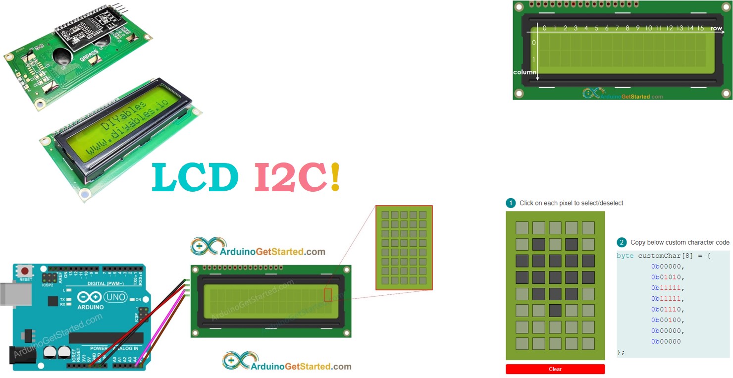
Arduino Getting Started
Learn: how LCD I2C works, how to connect LCD I2C to Arduino, how to program Arduino step by step. The detail instruction, code, wiring diagram, video tutorial, line-by-line code explanation are provided to help you quickly get started with Arduino. Find this and other Arduino tutorials on ArduinoGetStarted.com.
cobalt swan
Does anyone know of a battery operated handheld device that is purpose made for powering and displaying and interacting with serial output of devices? Basically something that you can plug in some arduino that outputs to serial and then interact with that? Changing baud rates, tiny keyboard, etc.
cobalt swan
Over USB, to be specific. Trying to solve ina generic the problem of needing to lug laptop around to read the results of tools that output over serial.
lean stone
back when you needed RS-232 to configure just about any piece of serious network or server equipment, there were some rather small and lightweight laptops that were preferred for that purpose. i forget the exact brands and models, but maybe Toshiba was one?
one downside is that your modern microcontroller board typically has 5V or 3.3V unipolar serial, not the true RS-232 bipolar serial that such laptops would expect
 gilded linden
cobalt swan
Over USB, to be specific. Trying to solve ina generic the problem of needing to ...
gilded linden
cobalt swan
Over USB, to be specific. Trying to solve ina generic the problem of needing to ...
look into a KVM Console - USB converter - then you can use any lapdock or any laptop you already own. They are common for anyone creating a crash cart for datacenter use
https://www.amazon.com/StarTech-com-Console-Portable-Laptop-Adapter/dp/B002CLKFTQ
and the budget version is one of these cables
https://www.amazon.com/Cable-Matters-Serial-Adapter-RS232/dp/B00J4N9T9C
cobalt swan
Oh! Sorry, I specifically meant serial over USB 😅
gilded linden
that cable should still work
in datacenter work, we often have to plug into network gear that have a serial console to debug
zinc burrow
lean stone
back when you needed RS-232 to configure just about any piece of serious network...
ive got a pair of asus eeepc701's i could use for that
but the PSU cable on them is toast, and they wont charge
zinc burrow
lean stone
one downside is that your modern microcontroller board typically has 5V or 3.3V ...
i think a max2232 can fix that?
outer brook
Why are premium brands of t slotted extrusion so expensive? T Slots, McMaster, 8020, etc.
Like 15 bucks for an l bracket.
proper escarp
misumi is more reasonable
 drifting ice
soooooooooooooooooo the modding scene for obsolete handhelds is ludicrously gargantuan...
i genuinely had no idea until now
onyx marten
concur -- i've been amazed at the number of odd corners i've turned up in just the last year!
drifting ice
You and me both pal! I didn't think I'd be learning hacking on a general hardware and firmware level via learning to identify VCC GND RX and TX via logic analyzer, while simultaneously learning how to access UART shells and probe/dump firmware chips, but here we are!
idle solar
Has anyone used Rust for embedded development? What is your opinions on it?
pine igloo
You still need to know c
 dim zenith
It took me longer to learn rust than it took me to learn assembly
If you’re willing to put in the time to mess with bleeding edge software that’s in its infancy, it’s quite handy and has a really tight-knit community
cobalt swan
Boosters will increase the voltage by pulling more amps, right?
or, where does the extra voltage come from
silver glacier
Yes, in a manner of speaking. Really what they do is chop up the incoming DC voltage and use some switching trickery in combination with an indicator and capacitors to increase the output voltage.
In other words they are switching between two circuits really fast and then filtering the resulting waveform (usually some kind of triangle wave or sawtooth) to get a (mostly) DC output voltage.
cobalt swan
huh. thanks.
hearty karma
But yes, power is conserved, so watts in will be slightly more than watts out (due to incompletely inefficient conversion) so you're right: if voltage out is higher than voltage in, current in will be higher than current out.
quaint rivet
okay, to @hearty karma and @silver glacier that talked about getting the vendors/suppliers to do their own DQA, how far can we negotiate a deal like that?
hearty karma
The usual procedure is to write it into the RFP/contract. How far you can go depends on the vendor, product, profit margin, schedule, etc. It is possible to go pretty far (it's common in medical and aerospace procurements).
 dull silo
Aluminum Mounting Grid product page states Wanna make your own? KiCad Python script grid generator available here for making any size your desire! Is there an .STL file? https://gist.github.com/tannewt/0acd1f6af48c43dc7e15243fe0af47ed
 pseudo zinc
dull silo
Aluminum Mounting Grid product page states Wanna make your own? KiCad Python scr...
pseudo zinc
dull silo
Aluminum Mounting Grid product page states Wanna make your own? KiCad Python scr...
I do not see it in their CAD repo: https://github.com/adafruit/Adafruit_CAD_Parts
hearty karma
dull silo
Aluminum Mounting Grid product page states Wanna make your own? KiCad Python scr...
You just want to cut one out or 3D print it? The pattern is pretty straightforward, either the Python code could be modified to produce a cutting path (if you're cutting it), or you could write a simple OpenSCAD program to generate it directly as an STL.
dull silo
hearty karma
You just want to cut one out or 3D print it? The pattern is pretty straightforw...
I’m looking simply for an STL file that I can import into a 3-D modeler app, and then into a slicer to print on a 3-D printer. I see if OpenSCAD will work. 
main hemlock
dull silo
I’m looking simply for an STL file that I can import into a 3-D modeler app, and...

Cults 3D
Adafruit has the Swirly Aluminum Mounting Grid for 0.1" Spaced PCBs and included a link to a KiCad python script to generate the same. But I don't have or know how to use KiCad but I do know how to use Fusion 360.
Using the description I created the sketch for one of the squares and us...

Printables.com
Identical to the Adafruit Swirly Aluminum Mounting Grid for 0.1" Spaced PCBs. | Download free 3D printable STL models
hearty karma
Good finds!
 dull silo
Thank you friends
cobalt swan
https://lcamtuf.substack.com/p/signal-reflections-in-electronic
This is interesting, even if I'm not yet following along

In some of the earlier articles on this blog, I talked about two important and hard-to-grasp phenomena that interfere with the design of high-speed digital circuits. The first one are signal distortions contributed by PCB parasitics; the other is the
summer dagger
Can I use IC Hook Test Leads ( https://www.sparkfun.com/products/501 ) to connect components to adafruit feather boards?

These are various leaded cables for attaching to multimeters, power supplies, oscilloscopes, function generators, etc. 5 pairs of IC Hook to IC Hook test l
hearty karma
cobalt swan
https://lcamtuf.substack.com/p/signal-reflections-in-electronic
This is interes...
There's a lot to understand there. Some systems (PCI bus comes to mind) actually use the reflections as part of their design.
quaint rivet
hearty karma
The usual procedure is to write it into the RFP/contract. How far you can go de...
how willing would vendors do this?
does it depend on negotiation power as well?
hearty karma
As in everything with vendors, it's a negotiation. Normally they'll expect more money and time for such services. How much more money and time is ... negotiable. And yes, like any negotiation, how much flexibility you can get depends on how much clout you have. Some companies (amazon comes to mind) just assume they have all the power and implement pretty unfair agreements. Other companies actually want your business and will try to meet in the middle. Personality is a lot of this. People with a mindset to come to a mutually beneficial agreement will generally achieve such agreements. People with a mindset of "there's gonna be a winner and a loser, and I wanna be the WINNER" generally don't fare well.
quaint rivet
Dang, okay, i guess thisll be an uphill battle for me
Cant believe management told us to continue doing tests on rejects
Waste of time
But then my coworkers were like "dude, that's still on paycheck, decreasing work would make us potentially lose money" and such
@hearty karma is there a way to make our procedures more efficient but still retain our paychecks?
Like, how do you negotiate things like this without leveraging your own and your coworker's pay
Also, why do i feel like chinese vendors arent the types to be willing to dispatch their QAs to assisst us
hearty karma
That's usually an easy thing to negotiate: think of it from management's point of view: they pay you the same, but effectively get more productivity. Efficiency is generally desireable.
quaint rivet
hearty karma
That's usually an easy thing to negotiate: think of it from management's point ...
Is there a way to prove it theoretically?
Management usually demands document proof or some sorts
hearty karma
Given fixed cost and greater productivity (which is what you're proposing) is a pretty simple proposition.
quaint rivet
hearty karma
Given fixed cost and greater productivity (which is what you're proposing) is a ...
eh, if only
im just a trainee with either my boss or a "feedback website" to rely on
the feedback website requires document proof so i only have my boss
problem is, my boss is also handling a lot of work recently, i don't know whether he have time to listen to my request nor to debate management
hearty karma
Personally I wouldn't let any of that stop me, but that's just the way I am.
quaint rivet
hearty karma
Personally I wouldn't let any of that stop me, but that's just the way I am.
Here's another thing : I can only theoretically prove that this will hurt our workflow when we receive an influx of products
the fact that we're only working with one sample for now doesn't really help the feel for the case
silver glacier
There's no #help-with-tools channel, so I'll ask here: I'm in the market for a new rework station at some point. Can someone who has used both the ATTEN ST-862D and Quick 861DW rework stations weigh in on the pros and cons of each? They seem very similar, but the ST-862D looks a bit more compact. I would be using this both for rework and on 3D prints.
https://www.adafruit.com/product/5238
https://www.adafruit.com/product/3941

If you've ever made a mistake when surface-mount soldering, you'll know how much of a pain it can be to fix it without the right tools. It can add critical time to a project and can ...

If you've ever made a mistake when surface-mount soldering, you'll know how much of a pain it can be to fix it without the right tools. It can add critical time to a project and can ...
inner linden
I guess we'll have to have a heated discussion here then
onyx marten
that kinda burns me up, really
summer dagger
How can I measure the battery level of a battery connected to an adafruit feather board?
summer dagger
summer dagger
How can I measure the battery level of a battery connected to an adafruit feathe...
 idle solar
May someone explain the difference between FTDI and USB to TTL? I'd like to use either or as a serial monitor to view on my PC.
 delicate quarry
idle solar
May someone explain the difference between FTDI and USB to TTL? I'd like to use ...
delicate quarry
idle solar
May someone explain the difference between FTDI and USB to TTL? I'd like to use ...
FTDI is a company that made a name for themselves making the commonly used FT232 chip used for many USB-to-TTL, to the point that their name at some point became colloquially synonymous with the latter. USB-to-TTL is more a general function that can be achieved with many different chips today.
silver glacier
Or more accurately USB UART.
 late socket
Can tb6612fng motor driver drive 2 n20 dc motors for line follower?
Also, did anyone try with drv8833 motor driver to run two n20 motors
600 rpm
hearty karma
I suspect that motor driver can drive DC motors
proper escarp
late socket
Also, did anyone try with drv8833 motor driver to run two n20 motors
yes to both
but... 600 rpm??
this is really fast
late socket
No
hearty karma
For a DC motor, it isn't. For a stepper, it is.
late socket
The i may run it in 60- 100rpm
proper escarp
hearty karma
For a DC motor, it isn't. For a stepper, it is.
I know. but using 600 rpm at output shaft for line following would be really difficult.
hearty karma
True. I'm guessing it's geared down before the wheel.
late socket
proper escarp
I know. but using 600 rpm at output shaft for line following would be really dif...
For LFR, i will be using 60 -100 rpm.
So, it will run for sure
Right?
proper escarp
yes, it should.
I have been using drv8833 on my bots with n20
I am just confused about how do you plan to use a 600 rpm motor at 60 rpm.
 proper escarp
seems to be boost converter
but impossible to say without looking closer
as for "getting hot": don't know, but it doesn't overheat
late socket
It's a dc to dc buck converter..
proper escarp
there are many to choose from
but still, how do you plan to use the 600 rpm motor at 60 rpm?
if you just feed it 10% power, the torque will be extremely low, so most likely it won't be able to move the robot.
or is 600 rpm before the gearbox, and further reduced down by the gearbox?
outer brook
<Windows> Is there a way to unlink my Documents/Github folder from OneDrive backup? OD really interferes with Github
I could only find a way to unlink all of /Documents/
onyx marten
move your github folder elsewhere? (it doesn't have to be in Documents) -- and you should be able to literally move it without any disruptions to github (any editors that have saved paths will be SOL 😀 )
silver glacier
Yeah I put nothing in documents for that exact reason.
formal spruce
I put my things in like, C:\Coding\repos\
what grinds my gears is when applications are installing themselves in places like C:\users\<myaccount>\Appdata\Local\<program>\
the .exe and all
silver glacier
That's the standard place to install things for single-user programs. For example, Steam uses it because games are associated with a specific login, and there can be multiple users on a single machine.
formal spruce
Steam.exe is not located there. I know they store user-specific data but the installs themselves?
worn ferry
I wanted to see if I could ask an AI chat about configuring a chip. Just to see if it could. My coworker suggested I try Google Bard.
"I'm programming in Arduino, how can I configure the output pins of the MCP23S08 over SPI?"
So, how did it do?
Mind you, I did NOT point it at the datasheet. That was my exact prompt to start with.
Well, it dug up the datasheet, parsed the whole thing, figured out that you need to send the chip's address (which is weird for SPI), pulled out the registers for setting both IO direction and state, and spat out some Arduino compatible chunks to try.
But, here's where it went wrong. It thought you should bitwise or the chip address with the register you're trying to write to.
After a couple pokes, talking to it like a person, I did convince it to split the two into two separate transfers.
"That's still not quite right. The chip address should not be bitwise or with the register address. They need to be two separate transfers."
Overall, I'm actually impressed. No, it didn't get it completely right on the first try, but I didn't expect it to. However the fact that it got as far as it did on the first try is pretty good if you ask me.
onyx marten
there is a definite "art" to getting the various AI models to produce actionable output, but i am finding the github copilot to be pretty slick for some instances (enough that i'm still paying for it)
worn ferry
Yeah. Expecting it to spit out usable code on its own is asking for a bad time, but I can definitely see myself asking something for a bit of help. I picked this scenario specifically because I already knew all the answers. If I ask it for something I'm not actually sure about, I'll definitely double check what it generates, but it could be a nice starting point.
Next I might try asking about the SSD1306 OLED display driver chip, and see if it can handle that thing.
formal spruce
I managed to get chatGPT 4.0 to spit out some monitor-specific screen buffer copying into a Texture2D in the Unity game engine and it was only missing a few lines which 'we' figured out by chatting back and forth based on the behavior I was getting (as the code had no runtime or compile errors)
onyx marten
yeah, that's when it starts getting a little strange...
worn ferry
As long as it's spitting out code that's at least readable
It's when it starts giving you things that you can't even understand to try and ask for more help on that you've got a problem there.
silver glacier
formal spruce
Steam.exe is not located there. I know they store user-specific data but the _in...
I'm talking about games installed via steam.
formal spruce
That's not where steam defaults to for game installs though, either.
silver glacier
On windows it's AppData.
Might not be in AppData/Local specifically, but it's definitely in AppData.
formal spruce
C:\Program Files\Steam\steamapps is the default install location for game installs through Steam.
silver glacier
Ah I'm probably thinking proton then.
formal spruce
Yeah, unless that changed in the past 4 weeks that's the default install location for Steam on Windows native.
I help run a LAN event a couple times a year and also have been resetting my own machines with steam installs, so it's kind of drilled into my head at this point.
silver glacier
Side note: I will never forgive Microsoft for putting a space on Program Files.
formal spruce
As far as I'm aware with Proton, that sets up a skeleton windows install environment and folder hierarchy unique to each title
silver glacier
Yeah, on *nix the default is in ~/.local/share/steamapps or something like that.
formal spruce
apparently used to be ~/.local/share/Steam and now it's ~/.steam/steam/SteamApps/common, not sure how recent that change is
silver glacier
More recently than I last installed it on a fresh system, apparently.
In the past I've put all of my steam stuff on an external HDD. Just built a new 'work'station though with 4x4TB SSDs that I'm going to set up with ZFS.
formal spruce
anyways, with windows I've mainly only seen malware installed in the appdata userspace, or annoying services that programs shouldn't really be using to begin with imho
quaint rivet
@hearty karma another question, sorry if this question drags for this long. Does the model that you propose apply to every business model or only for certain models?
is there a difference between chinese vendors perhaps?
because my mentor just explained to me that if we do ask for the supplier's DQA to help us create samples that are up to spec, they will demand us to buy more from them
and this doesn't change with our company reputation nor negotiating power
hearty karma
There is totally a difference between Chinese vendors. Also, Chinese vendors are not like US vendors, and they don't think of contracts the same way we do. In order to get reliable quality, you have to understand and work with cultural differences much more than you do with US vendors.
Your mentor is only partially correct: they will want something in return, but it doesn't necessarily have to be volume.
And it absolutely does change with negotiating power.
quaint rivet
hearty karma
And it absolutely does change with negotiating power.
well apparently not with our case so, sadly i dont think i can come forward with the idea
quaint rivet
hearty karma
There is totally a difference between Chinese vendors. Also, Chinese vendors ar...
this might be a huge factor
ah phooey, the price of reaching out the medium to lower income household
hearty karma
Well, your negotiating power is pretty much fixed, so while it does in fact vary with your negotiating power, you probably can't change that power.
silver glacier
You could always threaten to find another vendor. If they care about you as a customer, then they'll probably come around assuming your requests aren't too unreasonable. If they don't, you probably don't want to be doing business with them anyways.
quaint rivet
Pfft, like that would work for a chinese vendor
hearty karma

Small Business - Chron.com
Cultures and subcultures exist on national and internal levels of the business world. Globalization of business has caused these cultures to adapt to one another. Subcultures spring from overall, large cultures. Understanding a company's subculture and how it is derived from the larger business culture will help ...
zealous ember
silver glacier
Side note: I will never forgive Microsoft for putting a space on Program Files.
It's especially hilarious that there is at least one program created by microsoft for windows that can't handle being installed in program files due to the space that microsoft put there 😂
silver glacier
Another "fun" one: by default ntfs is case insensitive. Of course, things still break if you rename a file and only change capitalization.
formal spruce
Have been through the weeds fixing a git repo a few times because of this
 quasi mango
Apple's HFS and APFS filesystems also support case insensitive naming. Good for hours of fun, especially for large projects where filenames can clash. I can see where case insensitivity can be useful for naive users, but making it a feature of the filesystem itself rather than the file manager (finder in Apple's case) never made much sense.
silver glacier
And then there's zfs... which lets you do both (it defaults to case-sensitive of course).
onyx marten
i'll stick with the sanity of *nix, thanks
hearty karma
MacOS is running on *nix (BSD, specifically), but using its own filesystem format.
onyx marten
yeah 🙄
idle solar
I recently came across this: http://www.tuxgraphics.org/electronics/200905/embedded-tcp-ip-stack.shtml . When will there be a time to use this? Say over a RPI or ESPxx? Curious what about folks views.
cold pebble
"identi.ca" (does that still exist?) ...this page was last modified 2012, but it could presumably be used in a project
icy moth
Fascinating news here: https://www.theregister.com/2023/11/28/microsoft_opens_sources_threadx/
inner linden
Interesting that they didn't open source it when they acquired Express Logic, but ... I guess you have to thread carefully.
silver glacier
Probably couldn't legally due to internal library dependencies.
Whenever previously proprietary software is open sourced, it needs to go through a 'sanitization' process first.
And future binary releases from the company probably won't be reproducible from the publicly available source code.
inner linden
And/or they had other plans that haven't necessarily panned out.
onyx marten
inner linden
Interesting that they didn't open source it when they acquired Express Logic, bu...
naw, they were just needling us
 random cypress
I'm trying to remotely help a family member install a graphics card into their new gaming PC. I haven't touched this stuff in like 15 years. In advance of our next phone call, I'm thinking about what could be going on with their PSU. I'm hoping it has enough PCIe power outputs (two 8-pin ones) to power the gfx card. I was thinking that maybe it's modular and we'll need to get a cable like, idk, this one if it didn't come with the PC. Then I looked closer. A splitter where both ends go into the same device? What's the point of that? Why not just send all the power through one 8-pin connector?

Connectors A- 8 Pin male. Connector B - 2x 8-pin (6+2pin) male. PCIe ribbon cable Genuine new copper cores, no recycled materials 8 pin male end to connect to the power connector of the power supply and two 8 pin(6+2) male ends to plug into the video graphics card;
 solar pagoda
random cypress
I'm trying to remotely help a family member install a graphics card into their n...
solar pagoda
random cypress
I'm trying to remotely help a family member install a graphics card into their n...
Because people want to buy cheap power supplies that only have one 8 pin connector, then wonder why when they overclock the card it plays up due to the power supply not able to supply the load....Most times this works without issues. Graphics cards have increased in the amount of power they need therefore additional pins have been needed due to the copper tracks with less pins unable to supply the load.
quaint rivet
alright guys, question, is there like a jig or a mechanical part out there that can be used to strongly grip metal plates from above?
something that has a strong grip
 verbal aspen
It's not quite clear what you mean by "above"? Are you trying to suction-cup the flat side of a plate, or grip it around 4 points of its perimeter to lift it up flat, or grab it from the edge like toast popping out of a toaster, or...?
cold pebble
I suppose something like this is overkill https://www.wehausa.com/slab-plate-scissor-lifting-clamps-s/2722.htm
idle solar
Has anyone used with this sd-reader library? http://www.roland-riegel.de/sd-reader/. I'm having trouble reading the microSD card I have with the MicroSD Card breakout board.
quaint rivet
verbal aspen
It's not quite clear what you mean by "above"? Are you trying to suction-cup the...
The first and second one
Something to lift metal plates flat side up
We need something strong to test the strength of its adherence to another component
quaint rivet
cold pebble
I suppose something like this is overkill <https://www.wehausa.com/slab-plate-sc...
I think so, it's too big and clunky for testing purposes
We need something non conductive and precise because we are testing out batteries
hearty karma
solar pagoda
Because people want to buy cheap power supplies that only have one 8 pin connect...
Additionally that class of hardware is heavily cost-optimized. The wires from the power supply are as thin as they can get away with (and often not copper, but copper plated aluminum). The power supply regulation is somewhat marginal. And the traces on the graphics card are often thin (1 ounce) copper with limited current carrying capability and high voltage drop.
random cypress
hearty karma
Additionally that class of hardware is heavily cost-optimized. The wires from t...
Wow. Would it not cost only pennies (compared to the $200+ price of the whole card) to have a slightly beefier port on the graphics card that can divvy up the current internally however many ways it wants for its hair-thin traces? Presumably this is how the splitter cable does it at the PSU end?
hearty karma
While it could, pennies are the name of the game in cost optimized hardware like this. Additionally, both the power supply designer and the card designer are assuming the other parts are marginal, so even a beefy port might not receive sufficient power.
random cypress
Wowee.
hearty karma
It is a kind of broken optimization as the power connectors aren't free either, and including two power ports has costs of its own. However, they're also stuck with an existing de facto standard for connector type and power draw expectations.
random cypress
Right ok, I was looking for a statement like that or else I was going to still be confused
"It's somehow cheaper to use two thin cables rather than one cable that can carry twice the current?"
hearty karma
It is arguable the commodity PCs are basically a collection of broken optimizations.
hearty karma
Additionally, it's kind of a flex to have a card "so powerful it requires two additional supply cables"
 sudden scarab
Hello my good people. I'm hoping you can help direct me to the right area/product to get some help.
I'm working on this project to build a pipboy 3000 - https://learn.adafruit.com/raspberry-pi-pipboy-3000?view=all
One of the required items is an Adafruit model 2441 Resistive touchscreen with a breakout header - https://www.adafruit.com/product/2441
The problem I'm running into is availability on the 2441 screen. I'm not finding the exact model availabe on adafruit, amazon, or ebay. I can find plenty of 3.5" screens, but none with the additional breakout pins.
I'm wondering if there might be a different compatible version of the 3.5" screen for the RPi. Can you offer any guidance on this?


Is this not the cutest, little display for the Raspberry Pi? It features a 3.5" display with 480x320 16-bit color pixels and a resistive touch overlay just like our popular original, ...
This is a diagram that shows the back of the 2441 Adafruit display with the breakout header circled
 sudden scarab
This is hopeless
main hemlock
sudden scarab
This is hopeless
There are parts availability issues for many displays
Note that the Learn Guide has been deprecated as well.
 cosmic quest
Hi everyone! I am hoping to get a recommendation. I have a 5m WS2815 12V strip I'd like to use for hyperion, so putting it on the back of my TV. Ideally the solution would allow me to power both MCU and RGB Strip (I have a strong enough power supply) as well as connect to USB to drive the lights. I'd ideally like to avoid controlling the lights over Wifi. I know I can get a 5v MCU and a buck converter, but hoping for an all in one solution, especially if that solution can power itself and the 5m strip (maybe not through the device but if the device has a 12v direct connection or something?).
Is there anything like that in existence?
A second idea would be just powering the device over USB and a separate adapter for powering my lights. I think that is a more common case (any almost any device would work as long as I have a common ground acaross he board).
hearty karma
There are some MCUs that have onboard voltage regulators that can accept 12V, but it might run hot doing that. A buck converter seems like a sensible approach to me.
pseudo zinc
cosmic quest
Hi everyone! I am hoping to get a recommendation. I have a 5m WS2815 12V strip I...
Maybe check out the rp2040 Scorpio: https://www.adafruit.com/product/5650
 nova finch
This is pretty impressive...
https://www.youtube.com/watch?v=HKpBhE7QVAI
 worn ferry
I'm sitting here trying to figure out just what files I need, and what formats they need to be to get a board assembled by PCBWay.
Then I find out they have an official one click ordering plugin for KiCad. That's actually really nice.
One thing I'll be interested to see is how they handle the fact that I have two chips, but I've designated them to be sockets.
 woeful whale
nova finch
This is pretty impressive...
https://www.youtube.com/watch?v=HKpBhE7QVAI
woeful whale
nova finch
This is pretty impressive...
https://www.youtube.com/watch?v=HKpBhE7QVAI
Huh I wonder how easily you could use a higher resolution display with that
formal spruce
woeful whale
Huh I wonder how easily you could use a higher resolution display with that
A few problems with that I think 1. viewing angle issues would blur it a lot 2. issues with refresh rate being able to keep up. Skimming through the breakdown article they wrote they have it running at ~1200 RPM. I think the refresh rate needed is too much for any display to be capable of doing, which is why you always see these pesistence of vision displays made out of LED strips or grids instead of full displays
woeful whale
Maybe some sort of OLED. But you would need something that can refresh MUCH faster than an SSD1306 lol
formal spruce
they also mention that the RP2040 in particular can update all GPIO pins in the same clock cycle while also being able to poll the IR sensor they're using
super cool little project that works against very low level limitations pretty well it seems
not quite the same but I have thought about trying to make one of those 'hologram' displays where you create a pyramid, or even just a single angled slant, with screen above or below that has up to 4 angles of the same video output so they're 'projected' onto the pyramid or slanted glass/plastic
 fast kelp

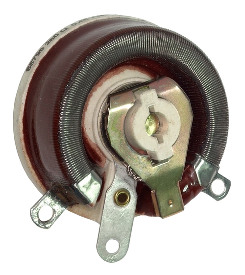
 pulsar shale
Wayback Machine: 2011-12-02
 worn ferry
Blast. My board assembly order was approved, but I was expecting to get sockets for the chips, not chips themselves. Hmm... How to fix it...
worn ferry
When in doubt, contact support. I guess this isn't an uncommon thing. They just said to contact the sales rep.
zealous ember
what's not working?
I would just set it to input, and serial print reading it and see how it behaves when pressed vs not pressed. Maybe it needs a pullup or pulldown 🤷♀️

What kinda button wiring is that? So it needs INPUT_PULLUP? 🤔
http://152.32.187.208:8080/yd-data/YD-RP2040/ amazing website. Doesn't even have a domain name😆
 high summit
hey guys! really need your help on my final year project. here's what I'm building
The ESP32 is configured as both a master and a slave in an IoT setup.
The slave reads temperature values and publishes them on the (deviceID + "/temp") topic.
The master subscribes to this topic and monitors if the temperature exceeds 22 degrees. If the temperature exceeds the threshold, the master publishes a control signal of 1 on the (deviceID + "/toggleLed") topic.
The slave, subscribed to this topic, checks the toggleLed value. If it is not empty and equals 1, the slave sets a specified GPIO pin (connected to an LED) to HIGH, illuminating the LED.
Problem: onMqttMessage function is not being called!
Here's the link to repository containing all the code
https://github.com/moizghumann/IoT_Temperature_Control/blob/main/sketch_dec3c.ino

GitHub
Contribute to moizghumann/IoT_Temperature_Control development by creating an account on GitHub.
worn ferry
Well, that was a learning experience I didn't want to have, but I'm glad to have had it.
My current project has suffered a bit of a setback, but I've learned a couple things.
One, the TinySPI library has the data pins reversed for some reason.
Two, PROGMEM doesn't work the same on the ATTiny85 as it does the Trinket M0.
silver glacier
Those are two very different microcontrollers.
worn ferry
Yeah, but I figured the compiler would handle the differences in PROGMEM. Still, I got lucky in that everything I was hoping to put in there actually fits in my limited RAM.
That said, I'm still going to have to revise my board layout for the change in pin assignments.
silver glacier
I'm assuming you've read this?
https://www.nongnu.org/avr-libc/user-manual/pgmspace.html
Some of it boils down to the fact that C(++) was never designed for the modified Harvard architecture common in microcontrollers.
worn ferry
Yeah. I kinda forgot about it because all my testing was on the M0, and I didn't need do do anything like strcpy_P. Falsely believing that somehow things were different these days.
I didn't realize it was somewhat of an architecture specific thing.
silver glacier
With microcontrollers you are going to have to deal with architectural differences more often than not. Different devices have different memory maps, and you are almost always running on bare metal, so there's no operating system providing abstraction.
worn ferry
Yep. But, now I know. So that's a good thing.
It's also good that I did this testing at all because I found a different problem as well that would have stopped me from ever figuring it out.
And made me waste $100 in having boards made that were wrong.
silver glacier
oopsiewoopsie
worn ferry
Now... Do I actually go through and put everything in PROGMEM properly, or do I just let it fester in RAM? Decisions, decisions.
I probably should put it in PROGMEM, just to show that I can.
Though since I have a working version in RAM, the more important thing is to redo the board.
Still don't know why DO is MISO and DI is MOSI. Just, why, Atmel? Why?
silver glacier
How much data are you talking about here?
silver glacier
worn ferry
Now... Do I actually go through and put everything in PROGMEM *properly*, or do...
Probably to get rid of the master/slave terminology.
worn ferry
A few hundred bytes. It fits just fine, and I'm not planning to need much more, so if it stays there, it's likely not a problem.
Also I doubt that it's to drop the master/slave terms since their datasheet still uses them.
silver glacier
worn ferry
A few hundred bytes. It fits just fine, and I'm not planning to need much more,...
Yeah, keep it in RAM. AVR chips load instructions from flash synchronously, so it takes quite a few extra clock cycles to load data from flash.
worn ferry
Good to know. I'll leave it in RAM and leave the PROGMEM stuff for another project. For now though, sleep.
silver glacier
idle solar
Can anyone recommend a stable/up-to-date microSD/SD card library for their AVRs?
Is there a capacity limit that the MCU can handle? I feel like I'm not understanding something here so I would appreciate if someone can educate me on this.
I have been stuck on this for a while, perhaps I might abandon the SD card part of my project if that's that case... Which I find it hard to. So, can someone give me an opinion, if it is worth digging through the code and understanding the nitty gritty details?
I've seen a few blog posts using the same mircoSD breakout board I have using a different SD library (FatFS to be specific). Though I found that others were using a SD adapter to hook it up, seems to be a common thing throughout. Maybe someone can correct me on this. Don't want to be pulling my hair out on this.
 outer jetty
I'm with you on this one, MercyMoon. Does anyone know a source for vibration/haptic motors that come with connectors attached? I'm struggling with getting good solder joints for the 30 gauge leads, especially when trying to attach them to longer leads. Does anyone have any tips for soldering tiny gauges?
naive salmon
I glue mine down, and have an extra solder joint farther up the wire
A hotglue gun is a tool that companies use for this sort of things in factories, and it seems to work.
worn ferry
I figured it out. I now know why the ATTiny85 appears to have its SPI pins backwards.
Because I've been looking at it from the wrong direction.
The SPI pin designations are only used during programming. During which it's the slave device, not the master. That's why it's MOSI/DI and MISO/DO.
hearty karma
Oh, that makes sense! Thanks for sharing your findings, that knowledge is useful.
worn ferry
Time to sit back and wait for the response from PCBWay. I'm like super paranoid that I've done something wrong, again. But I've gone over the board and compared it like 10 times with the functional build, and everything appears correct. But I'm still concerned about the assembly part since last time I submitted it they wanted to supply the ATTiny85 themselves, at a cost of like $5 each.
Here's hoping that changing the "value" for it to be a socket is enough to get them to put sockets on. Apparently using the socket footprint doesn't work.
hearty karma
DIP package?
worn ferry
Yep. Not currently confident enough to start using ISP headers, so I need a socketed MCU.

I know I'm paying more for a small run, but over 300% what I can get them for from Digikey? No, I don't think so.
Weird thing is that it's the only component on the list that's like that. And that's factoring in the fact that SMD components you have to allow for losses due to loading the machine.
hearty karma
That is weird, they probably get them from LCSC https://www.lcsc.com/product-detail/Microcontroller-Units-MCUs-MPUs-SOCs_Microchip-Tech-ATTINY85-20PU_C965497.html
worn ferry
I appreciate that LCSC has photos of (presumably) every part they stock.
Yep. That's a resistor.
 cold prism
I'm looking for a relatively small board with USB C that can recharge a 500mAh 1s lipo that also has a passthrough for data