#general-tech
1 messages · Page 24 of 1
 delicate quarry
What should you do with the 4th button?
 rugged field
idk
delicate quarry
“Fidget button”
rugged field
you can play tetris with 4 buttons
 icy moth
Nah, by that logic a circular watch should have circumference/button width buttons
rugged field
yes
it should
or a rotary encoder
like the ben ten watch where you can turn the outer frame as an input
delicate quarry
I’m imagining a giant rotary encoder on your wrist, and I gotta say, it does make for a novel watch…
rugged field
yep
delicate quarry
When will you have stock?
icy moth
delicate quarry
I’m imagining a giant rotary encoder on your wrist, and I gotta say, it does mak...
I’ll just design a version of Apple’s Digital Crown
rugged field
or a rotary switch
icy moth
That thing is so complex, idk have they even mill all the parts for it
rugged field
you turn the grippy ring around the screen and it turns the rotary switch as an input
icy moth
That would be pretty hard to do without spending $$$$ on a prototype
rugged field
i can confirm the 4 $
the full prototype for my RP2040 IoT/cellular project costs like $500 total
icy moth
Plus the level of detail required would mean I’d need advanced manufacturing capabilities like 5 axis CNC machines
rugged field
or you pay a website that has a factory in china do it for you
icy moth
I checked pricing of getting prototypes for an anodized aluminum case for my watch, $$
rugged field
it takes a while but its pretty easy
well i think the problem is not the complex manufacturing but the anodized aluminum
delicate quarry
Might be easier to turn a knob with display into a watch at that point, rather than the other way around.
icy moth
Plus I’d need a glass bottom for the inductive charging
delicate quarry
Imagine https://www.electronicsweekly.com/news/products/displays-2/rotary-knobs-with-a-display-in-the-middle-2022-10/ on your wrist LMAO

Anders has introduced a family of rotary switches that have a circular colour TFT-LCD in the middle, as well as a push button function. Available with
rugged field
thats what im sayin
delicate quarry
Then make it
delicate quarry
Don’t we all
delicate quarry
Wow must be nice
icy moth
If I’m going to make an incredible product, I’m going to spend good money to make it very refined
rugged field
yea
delicate quarry
Six visits is a new 3d printer lmao
icy moth
My job gives me $52.50 for every hour I work
The government takes about $16 of that though
icy moth
Well, gov and 401k/benefits
rugged field
lol my parents pay me $10/hour when I organize stuff or build stuff for their business
rugged field
delicate quarry
Did you pay for it though
no it was a Hannukah present
i built a small table yesterday and i removed the background of the png of their logo and got paid in parts
icy moth
My business pays me 5% of revenue
rugged field
commission
icy moth
Which right now is $0 because I’m just getting things set up
rugged field
bruh
icy moth
Not commission, it’s pass through income
rugged field
oh
icy moth
It would be more but I’m devoting like 12.5% for R&D
icy moth
45% for operating and overhead expenses related to inventory and stuff
rugged field
ok
icy moth
30% because self employment taxes are a lot
rugged field
87.5% gone
icy moth
7.5% devoted for profits
icy moth
My cut of revenue
rugged field
oof
icy moth
 icy moth
I put it into the business when opening the account
rugged field
oh
icy moth
Business is hard. It’s why so many fail.
rugged field
what even is your business
icy moth
Oak Dev Tech
Discover the IcyBlue Feather, a low power FPGA development board in a familiar feather format. Featuring a Lattice Semi ICE5LP4K FPGA.
I run a small maker business
rugged field
so i could fill out a form and upload some files (and pay you a large sum of money) and you will prototype and manufacture my project
icy moth
It’s been around for a while but I just rebooted the business
rugged field
also i like the icy blue
 shell hearth
just forget it, throw some hot swap sockets on that bad boy
 lean warren
hey guys, lets just say you had 2 cubes that would be magnetically connected through an electrode...
and you need to transfer the knowledge from 1 side to the other.
so: you need to tell the other side: This is the DAC value, copy it and move to the end.
rugged field
have the main electrode in the middle of the cubes face and have smaller pogo pins that interface when the cubes lock together. now you have multiple individual connections between cubes that you can do whatever you want with
you can have an ATTiny on each face to handle communication between cubes and logging the DAC value to a central cube memory
each cube face can talk to the cube its part of and any connecting cubes and transfer and store data
or have each cube be independent excluding power and use an rf mesh network
you could have a LoRa module in each cube that all talk to a controller so all you need to do is transfer power between the cubes and they will all connect up by default
 hearty karma
lean warren
hey guys, lets just say you had 2 cubes that would be magnetically connected thr...
hearty karma
lean warren
hey guys, lets just say you had 2 cubes that would be magnetically connected thr...
There was a user on here a while back doing stuff like that. Cool looking touch sensitive light up blocks that hooked up magnetically.
 regal horizon
Magnetic hexagons for wall art were very popular a couple years ago. They magnetically connected together. The magnetic connectors that Adafruit sells in their store do have pogo like springs in some of them.
It's just a matter of time before Pixelblaze takes that concept and makes an entire fibonaci wall.
lean warren
thank you, you have helped me a lot. this project is going to go beautifully 🙂

lets go.
 jaunty socket
or playing a recorded sound automatically involve an audio-codec/DAC?
lean warren
yes. it gives you waves and frequency 🙂
jaunty socket
and you need a speaker on your board as well I guess ?
Like esp32-s2 dont have a speaker
or a headphones connector
I basically need to make my wheeled robot meows and hiss
 woeful whale
Esp32-s2 has a dac
So if there's support for audio playback, you can just connect that to an amplifier module
 steady gulch
and it does I2S for digital audio
delicate quarry
With the announcement of the new uno R4, are there any plans to explore anything with the renesas MCUs? Say, a possible circuitpython port?
It’s pretty exciting news, considering it’s kind of like a 5V metro m4
steady gulch
32kB RAM ?
delicate quarry
Actually nvm
Just saw the memory lol
Still, a pretty good option for an uno replacement
Clock speed is nowhere near samd51 either
But ehhh
Floating point.
delicate quarry
That’s a fair comparison.
 nova finch
steady gulch
32kB RAM ?
nova finch
steady gulch
32kB RAM ?
Hey 32K is a lot. That's like 6 VIC20s. 😄
steady gulch
it has an ESP32-S3 Mini 1 on it as a wifi chip, now THAT can run CP 😄
delicate quarry
RA4 is pretty low on their offerings though, might be interesting to see an RA6 with arduino or python support…
I was planning to develop a ramps shield for the m4 grand central, but now I may wait for a renesas mega instead…
 main hemlock
It doesn't have external flash either, so it's kind of like a souped up Trinket M0 with lots more pins.
maybe a 5V Arduino Zero is a better comparison
 teal wadi
nova finch
Hey 32K is a lot. That's like 6 VIC20s. 😄
teal wadi
nova finch
Hey 32K is a lot. That's like 6 VIC20s. 😄
Time to port https://en.wikipedia.org/wiki/Tiny_BASIC to it! :D
Tiny BASIC is a family of dialects of the BASIC programming language that can fit into 4 or fewer KBs of memory. Tiny BASIC was designed in response to the open letter published by Bill Gates complaining about users pirating Altair BASIC, which sold for $150. Tiny BASIC was intended to be a completely free version of BASIC that would run on the ...
What's with the yellow rectangle over the board?
 main hemlock
they haven't said; not sure if it is hiding some new design thing, or something more significant
teal wadi
It might just be graphic design stuff, too
In any case, does anyone happen to know the expected price? I've just skimmed that page
steady gulch
it's a new post-it note holder feature
 drifting ice
Status report: Old monitor might be going, and the 8-channel PiEEG module will be taking almost a full year to ship out. [april of 2024]
i am greatly distraught. /mentally drained, tired
On the flip-side, I'm making great progress on practicing how to drive!!
hearty karma
My old monitor started to get flaky, I replaced the electrolytic capacitors in its power supply and it's fine again.
drifting ice
Yeah, might take it apart if this keeps up.
hearty karma
Huh, I just checked, it was made in 2006, so not that old
drifting ice
dunno what could be the culprit though. It's always with VGA that it scales horribly sometimes, always squished with poor graphic quality at the most random times when I plug it back in.
hearty karma
VGA is tricky, as it's an analogue signal, so it has to get sampled, reclocked, reprocessed, etc.
drifting ice
Welp, it's either that [what I got] or buying a mini displayport to DVI adapter.
why did mini displayport exist-
hearty karma
I am indeed currently using minidisplayport to DVI adapter
drifting ice
epic
hearty karma
It's a nutty setup, it goes from the computer to the drive array (Thunderbolt), then on to the monitor for display.
drifting ice
hearty karma
It's a nutty setup, it goes from the computer to the drive array (Thunderbolt), ...
Hey, if it works, it works. Done worse before just to get something working. 😅
hearty karma
Heh, yup
teal wadi
drifting ice
Status report: Old monitor might be going, and the 8-channel PiEEG module will b...
You actually ordered that? You mad person :P
drifting ice
teal wadi
You actually ordered that? You mad person :P
I want to build myself an extra limb, and I'm not letting anything stop me.
teal wadi
drifting ice
```I want to build myself an extra limb, and I'm not letting anything stop me.``...
The good news is that, if my understanding of... everything is correct, as long as you keep yourself safe, this should beis definitely possible with current technology and knowledge, though you shouldn't be expecting realtime control
drifting ice
teal wadi
The good news is that, if my understanding of... everything is correct, as long ...
Either I will find a way, or try my heart out to make it a reality.
plus if it's just latency I need to be worried about, then that's nothing some practice and prediction can't fix imo.
 native hare
You could experiment on smaller mammals like rats
drifting ice
native hare
You could experiment on smaller mammals like rats
Do I look like a person who owns a full-blown laboratory?
teal wadi
native hare
You could experiment on smaller mammals like rats
That's VERY illegal without a license and an IRB (=institutional review board) approval.
native hare
Dont need a lab
drifting ice
teal wadi
That's **VERY** illegal without a license and an IRB (=institutional review boar...
also yes
teal wadi
It is also unethical without going through the proper channels.
native hare
Hmm ok
I find the ethical lines a little blurry given how society arbitrarily values certain animals, but that's beyond the scope of discussion
hearty karma
I don't have a full blown laboratory either. I have ... this.
 drifting ice
hearty karma
I don't have a full blown laboratory either. I have ... this.
drifting ice
hearty karma
I don't have a full blown laboratory either. I have ... this.
H O L Y F L I N T L O C K
teal wadi
You... uh... know this is better-equipped than a lot of places, right? :P
 pine igloo
hearty karma
I don't have a full blown laboratory either. I have ... this.
pine igloo
hearty karma
I don't have a full blown laboratory either. I have ... this.
That's cool man
drifting ice
hearty karma
I don't have a full blown laboratory either. I have ... this.
envy: maximum.
concern: integer_overflow_error
pine igloo
drifting ice
***Do I look like a person who owns a full-blown laboratory?***
Here's a good list
https://en.wikipedia.org/wiki/List_of_model_organisms
Some nice species also are:
Saccharomyces cerevisiae* (baker's yeast)
Caenorhabditis elegans* (nematode)
Drosophila melanogaster* (fruit fly)
Danio rerio* (Zebrafish)
Mus musculus* (Mouse)

This is a list of model organisms used in scientific research.
drifting ice
we've been over this. /slightly miffed
teal wadi
pine igloo
Here's a good list
https://en.wikipedia.org/wiki/List_of_model_organisms
Some ni...
Yeah, you can't exactly start working on these without the proper permits. Especially mammal research (mice!) require extensive review and approval prior to the experiments even beginning
native hare
I would like to experiment with daphnia since they reproduce with the same genes
pine igloo
Not if anyone knows 🙈
teal wadi
....
native hare
I would also like to experiment with fungi for composting bioplastics
rugged field
imagine you left your phone outside and when you came back to it, it was a bunch of circuit boards and components because the case decomposed
lmao
native hare
that is my dream scenario
drifting ice
🤦
native hare
The distribution of microplastics is beyond imagination
rugged field
ok but if you leave your water bottle outside, you come back to a puddle
native hare
Ideally we'd move on from PET bottles since those aren't compostable
Compostable here refers to ANSI and ISO standards for composting
drifting ice
I ask this of you with utmost sincerity; PLEASE, get a permit first and do this kind of experimentation in a place isolated from the rest of the world or in a controlled environment before we have an XK-Class End of the World scenario.
ok?
native hare
lol
drifting ice
I'm not joking.
native hare
I don't have the resources to perform these experiments
icy moth
Okie dokie let’s maybe take things down just a weeee bit
hearty karma
When I was a teenager, I read "Mutant 59: The Plastic Eaters". It was science fiction then. We're getting worryingly close now.
icy moth
hearty karma
When I was a teenager, I read "Mutant 59: The Plastic Eaters". It was science f...
it seems like we are there, I read they found microplastics in people's blood
hearty karma
I was thinking of things like Rhodococcus ruber and Ideonella sakaiensis
icy moth
Ah okay
teal wadi
So, I was thinking of building a new number crunching PC for CPU +memory-intensive tasks (think prime95, linpack, etc-like workloads CPU-wise). Both single- and multi-threaded performance are important to me, and the more threads I end up having access to for my money, the better. I'd also like the ability to later add a GPU and have it perform well, if needed. Because accuracy is a concern, I'll be keeping everything stock, so overclocking potential is not something I'm factoring into. Any parts CPU/motherboard suggestions?
hearty karma
Sounds like a job for PPC/ARM to me
teal wadi
hearty karma
Sounds like a job for PPC/ARM to me
In an ideal world, I'd agree (the power consumption is so much better), but, so many things expect amd64, it just can't be helped...
woeful whale
teal wadi
So, I was thinking of building a new number crunching PC for CPU +memory-intensi...
What do you mean because accuracy is a concern? Overclocking should not affect number crunching accuracy. (Except in maybe extremely rare cases (but I've never heard of a single instance of errors introduced because of a reasonable (not extreme) OC))
And Linus Tech Tips or another techtuber probably has a pc build video or cpu reviews that fits your spec
Maybe go AMD since they tend to have more performance cores (and cache with the x3d chips)
Mobo rarely ever matters for performance. Vrm performance affects power that can be pushed to the CPU, but usually a mobo just affects your IO options.
jaunty socket
drifting ice
```I want to build myself an extra limb, and I'm not letting anything stop me.``...
I want to builf myself an extra limb not letting anyone stop me and if they try i use my 6 arms to push them away!!!
learned today that us sellers cant export an fpga to me 😦
these embargos stuff is so confusing. Im in Canada but apparently theres an embargo on Canada too
i dont know im so confused
us sellers asking so many question and i dont know how to prove something im not or how to prove i wont do something
like they were asking if the board has an adc with a bandwidth above 55ghz
I haven't any idea what this even mean
 verbal aspen
If you're not buying a $10,000+ FPGA, the answer is "no".
(By that I mean that's an extremely high-end feature of very expensive chips.)
jaunty socket
i mean i saw this question for simple mcu on a board...
i guess i sound sus / not confident enough when i answer
like the end use question
i guess need it to make my robot car meows doesnt qualify for export
woeful whale
You shouldn't need an fpga for that
jaunty socket
or saying that i cant guarantee where it will end up in the world if it get stolen
woeful whale
That's a job for a wav or mp3 trigger or a decently powerful devboatd
jaunty socket
im just talking in general but i was specifically canceled on an fpga order
woeful whale
And I've heard HDLs are kinda hard
jaunty socket
possibly because of the export rhing
woeful whale
But really cool
jaunty socket
but ive had intrusive questions on simple electronics
woeful whale
Almost nothing outside of uber expensive rf equipment would have a 55GHz ADC
That's an insane speed only reserved for the most S tier of oscilloscopes
jaunty socket
yyeah but anything 33mhz and over is also export controlled
like arduinos and esp32s2
jaunty socket
and export refers to us export AND cbsa refusing to let me pick a package without questions
because they though id rexport it outside canada (the 33 mhz thing)
cuz apparently buying 4 of the same board is suspicious
woeful whale
Maybe they think that there's a possibility that you could export the technology to somewhere like Russia
But that's not really probable lol
jaunty socket
yeah that is the law they showed me
woeful whale
But that would make sense why they want to restrict stuff that could be used for rf stuff
jaunty socket
tons of electronics stuff restrictions lot of it is hobby scale specs
hearty karma
Arduinos are 16MHz, less than half of 33MHz
jaunty socket
another example was lidar with a range of 1km using less than 20 milliwatts didnt even know that was possible
some are 33mhz no?
hearty karma
Yeah, it's possible with the right signal processing.
jaunty socket
esp32s are 33mhz though pretty sure of that
woeful whale
Yes
jaunty socket
or something on them saaid 33mhz somewhere
jaunty socket
i was kinda annoyed because they asked technical specs and i dont even know what some of the words even meant
woeful whale
And even more technically LEDs are above 33MHz. They emit electromagnetic radiation in the THz
jaunty socket
i really wanted to say at some point i could tell you but it's not like you'd understand...
hearty karma
I had one person insist that it was the crystal frequency that mattered. Which is pretty bogus, as there are chips out there that use a 32kHz crystal and then PLL it to >100MHz
jaunty socket
i could have talked on how useless it would be on something like a mig35
but i felt that it was best to not display my military knowledge of hardware from janes 🤣
hearty karma
I remember the Soviet 8086 knockoffs
jaunty socket
yeah that was another topic i avoided
hearty karma
Good idea.
jaunty socket
not like theyd newd those 33mhz.chips anyway since they had soviet version of up to 486s
hearty karma
A nutty chip to clone, but military operations everywhere seem to just stick with whatever they've been using.
jaunty socket
like i could have BS talked about how to improve the accuracy of old sa9 gainful with 33mhz for an hour in general woth the image processing etc
but i felt like they wouldn't be the right audience for that 🤣
jaunty socket
hearty karma
A nutty chip to clone, but military operations everywhere seem to just stick wit...
the soviet also did everything they could to have a different standard from the west as well
So that if the gear was obtained on a battlefield getting the right logic level, making a battery that don't exist in the US, a custom socket in the wall etc
would all be issues that would have to be fixed before it could even be tried out
teal wadi
woeful whale
Mobo rarely ever matters for performance. Vrm performance affects power that can...
Doesn't mobo also affect max ram? Or is that no longer the case?
woeful whale
teal wadi
Doesn't mobo also affect max ram? Or is that no longer the case?
No. Memory controllers are on the cpu. But technically they do bc some only have two slots and others have 4.
teal wadi
woeful whale
No. Memory controllers are on the cpu. But technically they do bc some only have...
I remember the mobo chipset affecting it, but perhaps I was wrong or this was from a bygone age :P
Anyway, check out the link I gave you if you wanna learn yourself some verilog
woeful whale
teal wadi
I remember the mobo chipset affecting it, but perhaps I was wrong or this was fr...
That was back when north bridges and south bridges existed. Now, chipsets only affect overclockability and IO (pcie) pretty much
teal wadi
woeful whale
That was back when north bridges and south bridges existed. Now, chipsets only a...
TIL North/Southbridges are no longer a thing
hearty karma
It's an odd design choice, but just a recent one in a long string of peculiar design choices
jaunty socket
I think they mean like before a 32 bits cpu can uses a max of 4 GB in RMA
and 64 bits is around 16 million TB
teal wadi
woeful whale
That was back when north bridges and south bridges existed. Now, chipsets only a...
...and I guess whether or not you will end up with a buggy firmware that doesn't play well with linux
teal wadi
yeah :\ They were essentially glorified soundcards IIRC
hearty karma
Linux had no trouble understanding them, it's just they were so stripped down that they required bizarre timing that was impractical with a real multitasking operating system.
jaunty socket
I remember proposals to make linmodems back on freenode back then 😄
teal wadi
hearty karma
Linux had no trouble understanding them, it's just they were so stripped down th...
I mean, windows xp worked with winmodems and that definitely had preemptive multitasking
Or is that not the case?
Genuinely don't know
jaunty socket
I remember something like they didnt have the fallback protocol for modems
where you could connect in serial and do ATDT etc
even if you didnt have the specific drivers
but these didnt do anything standard
I see the one I had was a so-called "pure software modems"
that is probably why it was a dead brick on linux
jaunty socket
found this in a pocket behind my stove

manual to interface ttl with it if I wanted hidden in plain sight for the last 5 years 😦
is this a normal thing ?
jaunty socket
huh gps tracking on a 6.75 british pound package of meat ?
How does that make sense on a financial level ? Are gps devices really this cheap ?
verbal aspen
Are you sure it's GPS and not just like an RFID tag or temperature logger?
jaunty socket
but I doubt a satellite can see a box with a piece of steak in it from space ?
It would have to transmit to say where you took it
Box says protected by GPS
https://www.walesonline.co.uk/news/uk-news/co-op-branches-putting-meat-24430529 but can see it on youtube videos as well etc
sounds like BS to me
GPS device aren't 1$
verbal aspen
I presume the box is reusable and retained by the store when someone buys the meat, so the cost would be amortized over potentially years.
verbal aspen
Ah, yeah, thanks for the reminder. Don't believe anything you read for at least the next 24 hours...
jaunty socket
it was in a top type video posted today on youtube
so I didnt have the original context lol
native hare
Why don't we use FPGAs as personal computers
jaunty socket
how many pixels on your screen ? that should tell you why
suppose you calculate a shader on an fpga, how many logical units would you need to fit a UHD frame ? How much does an fpga with over 1m logical units costs?
That should start to tell you why ...
verbal aspen
native hare
Why don't we use FPGAs as personal computers
The programmability of FPGAs comes at a performance and cost penalty. One that was beefy enough to emulate a modern Intel chip would be 10x as expensive and power hungry at least.
jaunty socket
It's kinda the same class of question as to why we dont use 64gb of L1 memory as RAM
for the gps stuff above I know about airtags but afaik they hostile connect to any apple toys around so they aren't really gps but more like an apple-powered smart internal network
hearty karma
You can get an Arduino built out of an FPGA https://aloriumtech.com/xlr8/
woeful whale
jaunty socket
but I doubt a satellite can see a box with a piece of steak in it from space ?
GPS satellites do not receive. They only transmit a timestamp and the receiver triangulates its position based on the timing difference between signals.
jaunty socket
yeah I know that but it wasnt worth mentionning because wifi/bluetooth is very cheap vs gps
it mean it wouldn't be hard to make a box this big that can update its position to a server using some open wifi or something
the problem is getting its position
drifting ice
I FIXED THE PI'S TIME AND DATE PROBLEM!!!!
IDK HOW BUT I FIXED IT!!!
Also discovered a spare backup battery bank for smartphones is more than sufficient to keep the Pi running.
I AM ON FIRE TODAY
jaunty socket
@hearty karma says there isn't a way to search those FCC filling by says available document like "schematics" for those that forgot to asks to protect it right? 😄
woeful whale
jaunty socket
it mean it wouldn't be hard to make a box this big that can update its position ...
yeah it would need a cellular modem and stuff on it
nova finch
I'm in need of a 15" or larger hdmi display. Needs to be thin, minimal bezel. Doesn't need a stand (planning on building it into a picture frame). Trying to figure out best options. Not sure if I should get an off-the-shelf portable monitor, or build something out of a laptop replacement panel + hdmi-to-40-pin adapter. Anyone have any experience with this?
main hemlock
nova finch
I'm in need of a 15" or larger hdmi display. Needs to be thin, minimal bezel. Do...
how thin is thin? The last Dell 24" monitor I got is 2.1" deep without stand. It has minimal bezel except for the buttons on the bottom.
This is interesting; I assume you could unfold the bottom part to make it flat, but you'd have to conceal it: https://www.dell.com/en-us/shop/dell-14-portable-monitor-c1422h/apd/210-bbij/monitors-monitor-accessories
nova finch
main hemlock
how thin is thin? The last Dell 24" monitor I got is 2.1" deep without stand. It...
Yeah, I'm thinking that'd be a reasonable option. I was going down a rabbit hole of controller / display combos (e.g. https://www.amazon.com/dp/B07R6HNFSQ) and it's probably not worth the trouble
nova finch
main hemlock
This is interesting; I assume you could unfold the bottom part to make it flat, ...
Yep. There are a bunch of fold-up portable monitors. That might be my best bet.
nova finch
Turns out my spouse had a 21" Acer monitor sitting around. Without the stand, it's only 37mm (1.5") deep. That's not much thicker than some picture frames. Should work just fine.
Apparently, it pays to ask about stuff like that, especially when there's two work-from-home techies in the family. 😄
delicate quarry
You can get REALLY thin if you can hide the driver board elsewhere, but if you’re going for a single body device, off-the-shelf displays are a comparable option for a lot less work.
nova finch
Yeah, and I need to tuck an Raspberry Pi Zero in there anyway. Should be plenty of room.
hearty karma
nova finch
I'm in need of a 15" or larger hdmi display. Needs to be thin, minimal bezel. Do...
Laptop ones are quite thin (under 10mm is common), and they do generally work well with adaptors.
icy moth
Pro tip: make sure to redo your rats nest to avoid this neat bridge
 teal wadi
icy moth
Pro tip: make sure to redo your rats nest to avoid this neat bridge
teal wadi
icy moth
Pro tip: make sure to redo your rats nest to avoid this neat bridge
Kind of offtopic: Which model of microscope is that? How much does it cost?
icy moth
Some chinesium white label one I bought off Amazon
teal wadi
I should probably look at aliexpress then
hearty karma
That's where I got my binocular zoom boom microscope. It's not fancy, but it works for me.
 icy moth
Also, I heard y’all like USB C

This was also a great chance to validate two back LDO options
icy moth
Stray?
teal wadi
Not really, but we were discussing the CP2102 the other day
icy moth
Ohhh yeah
teal wadi
So I expected to see that
icy moth
That was for the keyboard feather wing that’s in the works
I don’t think you can program lattice with a cp2102
Or flash at that
teal wadi
Genuinely curious, why?
icy moth
Doesn’t support SPI protocol
teal wadi
Ah.
teal wadi
Ah, it's the USB-to-GPIO IC, not the UART one
My fault for not looking at the part number more closely
:P
icy moth
Yeah lol
teal wadi
I'm guessing you're wiring USB-C in usb2.0 compat
 pseudo zinc
I almost asked you why it was micro-usb and not USB-C
icy moth
Old design when I was still using micro b
It was useful because I have more usb micro b cables
teal wadi
All in all, I have... three usb.c cables
icy moth
I have one that I can use for programming stuff
I use USB C connectors on basically every new board I make these days. Figured IcyBlue should keep with the times
woeful whale
teal wadi
Ah, it's the USB-to-GPIO IC, not the UART one
MCP2221A?
 brittle gale
hello ya'll, not sure where to ask for assistance about adafruit boards
Hello, everyone, I am highschool student in need of assistance with my nonfunctioning Adafruit metro m4 express board.
if anyone knows the reason to why my board is not being recognized by my laptop, please let me know. I will greatly appreciate any advice.
Here are ways I tried to fix this:
- double press reset button
- Used a different cable
- Used a different port and laptop
- holding the reset button
- Check my anti-virus if it was blocking any feature
- Checked if i downloaded any adafruit drivers
- uninstalled and reinstalled com ports
- restarted laptop
Here is the context around the situation for when it stopped functioning:
I was preheating an mq131 ozone sensor using the digital heating circuit, and while I was doing that, I was also reading the voltage through the analog ports. All was working fine here, it was being recognized and it was reading the voltage. But then, I had the idea to preheat my mq5 along with the mq131, and so I stopped the circuitpython code, ejected the usb, unplugged the usb, and wired and coded the mq5. Then when it was time to plug it back in, my laptop cannot recognize the board and so I can't use it.
Thank you so much.
sorry, just to add on:
I suspected that it could be a power issue (not enough power or something like that) so i unplugged everything, yet it's still nonfunctional.
delicate quarry
brittle gale
Hello, everyone, I am highschool student in need of assistance with my nonfuncti...
Device issues can be tricky to pinpoint. Might seem like a dumb idea, but have you tried either restarting your computer, or connecting to a different pc?
brittle gale
yes, i have tried restarting my computer and used a different pc. Sorry, i did not put that on the list.
delicate quarry
Hmmm. Hopefully it’s just a transient error and not an actual component on the board….
brittle gale
hopefully i didnt short anything : (
delicate quarry
Oh, when you first received the board, did you ever update the boot loader? There is a rare issue of certain parts of the internal flash being overwritten if you’re using an old boot loader… https://learn.adafruit.com/adafruit-metro-m4-express-featuring-atsamd51/update-the-uf2-bootloader

Adafruit Learning System
Choo! Choo! ARM Cortex M4 @ 120 MHz coming thru!
brittle gale
yes, was that the uf2 file?
Also, thank you for taking the time to help me, I appreciate it.
brittle gale
https://circuitpython.org/board/metro_m4_express/
the first download on this is what i used
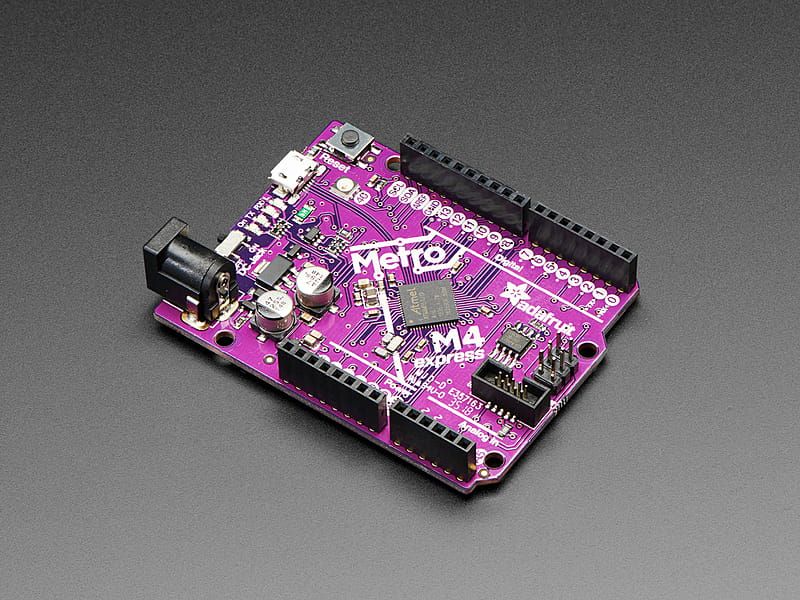
The most powerful Metro at this time, the Adafruit Metro M4 featuring the Microchip ATSAMD51. This Metro is like a bullet train, with it’s 120 MHz Cortex M4 with floating point support. Your code will zig and zag and zoom, and with a bunch of extra peripherals for support, this will for sure be y...
delicate quarry
So that would be the circuitpython uf2, not the boot loader update uf2.
If it is, in fact, an issue with the boot loader bricking the board, you’ll need some form of JTAG programmer to repair it…
brittle gale
oh wait, i did both

but i did use the old circuitpy uf2, i didnt realize it updated recently
actually scratch that
delicate quarry
That’s fine, as long as the boot loader wasn’t the old one
brittle gale
i used a diff board to put the bootload updater
i didnt put the bootloader on this board
ahhh
i have 5 boards total, i need to keep track of what i download on them.
thank you
 lost lily
#define LEDCubeBaseTemplate template <ledCubeAxis_t x, ledCubeAxis_t y, ledCubeAxis_t z>

LEDCubeBaseTemplate class LEDCubeBase {
is there anything better than doing this? seems very hacky
 lament ocean
Hi does someone knows if there is any way I can get custom sized displays? Or close to what im looking for about 23x44mm Display
verbal aspen
Custom would be quite expensive, so it's mostly just a problem of finding the closest thing off the shelf.
woeful whale
Aliexpress has a lot of differently sized displays
You could possibly find something there
lament ocean
Thx
 random ravine
So frustrating, finding an off-by-one. But it is now fixed.
 supple crypt
Did anyone else see Add 7-color e-ink display support listed as a CP8.1 thing and wonder if there's a new board or two coming?
Or if Adafruit/Pimoroni are about to make my Inky Frame with CircuitPython dreams come true?
 violet torrent
Just saw someone who used to use proportional fonts when coding, and I can't even imagine what that would be like
icy moth
supple crypt
Or if Adafruit/Pimoroni are about to make my Inky Frame with CircuitPython dream...
Pimoroni is working on MicroPython support last I saw
violet torrent
Am I weird for hating breadboarding?
icy moth
violet torrent
Am I weird for hating breadboarding?
I’d rather go straight to a PCB myself lol..
I have breadboards the I rarely use
violet torrent
Exactly! I much prefer PCB prototyping
hearty karma
I don't have the patience, I like instant gratification, and the ability to iterate on a design in seconds until I converge on something that does what I want.
 violet torrent
I find it's usually easier to focus on projects if they're in PCB form for some reason? But at the same time I do like the iterability of breadboarding when I do use it
teal wadi
violet torrent
Exactly! I much prefer PCB prototyping
heh, these days it's easier. Besides, PCBs are better for signal integrity and working with anything that switches faster than ~1MHz
icy moth
I cut my teeth with electronics by breadboarding transistors into things like adders, flip flops, mixes, etc..
It’s when you realize how much space it requires to do that with 2n2222a transistors
hearty karma
When working on my XL TTL project, I came up with a design for a TTL XOR gate built of discrete parts. Yeah.
 icy moth
I just made 2 transistor NAND gates
I could only fit one ripple carry adder on a standard breadboard
Back in 2019
Transistors, resistors, and LEDs lol
Fun stuff 🙂
icy moth
If it’s not clear from the video, I’m adding 2 2b numbers
woeful whale
Breadboards are really good for quicker, one-off, and/or analog circuits that you want to test before making a PCB. And perfboard is good for one-off prototype stuff that doesn't need to be easily produced many times.
violet torrent
the thing i hate about breadboarding is all the wires you need
icy moth
Yeah, I don’t always have the patience to place wires
 cold pebble
I've got projects on breadboards scattered around my house, some many years old now but still running fine
I don't mind soldering, but I really don't enjoy desoldering, so I don't solder up a perfboard unless I'm pretty sure (and I'm willing to forgo use of the components for an extended time if I change my mind)
icy moth
cold pebble
I don't mind soldering, but I really don't enjoy desoldering, so I don't solder ...
Sockets help solve this issue
But that’s an added cost and frustration
cold pebble
yeah, I do socket more expensive stuff, MCUs, etc
 inner linden
I think making my own perfboards, bent to my evil will, helps a lot.
Example:

There's a perma-proto section, a perf section, and some footprints for SMT parts that I end up needing. The breadboard section helps avoid the mess of wiring.
OTOH, I'm somehow cursed. Every single switching power supply I've ever designed has worked straight away but the little PCB that's just got a Qt Py and some linear LED drivers is a bag of trouble. :/
teal wadi
inner linden
OTOH, I'm somehow cursed. Every single switching power supply I've ever designe...
I think you've found your niche! :D
inner linden
No, puns are my niche. Switching power supplies is the side hobby.
teal wadi
The question is... can you make a pun involving switching power supplies?
supple crypt
icy moth
Pimoroni is working on MicroPython support last I saw
They've had it from launch
icy moth
supple crypt
They've had it from launch
I know, I was mostly talking about what has been developed beyond basic support
supple crypt
Yeah, my point is that I really want proper CP support. If they had it, I'd have already bought at least one of their Inky frames.
icy moth
Shouldn’t be that much work to get it working for CP
I think Scott (tannewt) has basic functionality working
teal wadi
I somehow find the fact that color eink is the new trend in the maker community very endearing
I'm looking forward to seeing what y'all are going to make with them!
woeful whale
inner linden
everything must have a qwiic connector now
 next spindle
teal wadi
I somehow find the fact that color eink is the new trend in the maker community ...
next spindle
teal wadi
I somehow find the fact that color eink is the new trend in the maker community ...
I made, predictably, a picture frame for my partner. Earned a lot of brownie poins there.
 outer brook
next spindle
I made, predictably, a picture frame for my partner. Earned a lot of brownie po...
outer brook
next spindle
I made, predictably, a picture frame for my partner. Earned a lot of brownie po...
Mind linking the display?
next spindle
The Pimoroni

Bold, will hold! A big, beautiful, 5.7" (600 x 448 pixel) 7 colour electronic paper display for Raspberry Pi.
I also made an enclosure for it, and would be happy to share the Illustrator file for that

 regal horizon
@next spindle We have a #show-and-tell channel just for showing off your projects either completed or in progress. Nice project!
teal wadi
next spindle
I made, predictably, a picture frame for my partner. Earned a lot of brownie po...
Aww, that's such a sweet thing to do! :D
 river hatch
I noticed that Microchip's website now says that the ATmega328P is "Not Recommended for new designs." There is a new version, ATmega328PB, which is similar, with only a few backward-incompatibilities. However, I noticed that the ATmega328PB does not seem to be available in a DIP package. Is this the end of through-hole microcontrollers?
That would put an end to "breadboard Arduino", and it would also make it impossible to make something like the "Make Your UNO Kit" using only through-hole components.
river hatch
violet torrent
Am I weird for hating breadboarding?
No, you're not weird. (Or, perhaps more likely, I am weird too.) If I feel confident in my design (which is usually the case if it's all microcontrollers and digital chips) I will go straight to designing a PCB in KiCad.
If I feel uncertain, I will breadboard a test circuit first, to test out the thing I'm not sure about. (This is often the case if it involves transistors or anything analog.) Just a few days ago, I had an idea that involved a couple of MOSFETS, and using a voltage regulator in a somewhat unusual way. I thought it would work, but I breadboarded it, and when I applied power, it set the breadboard on fire. So, good thing I didn't go straight to a PCB with that idea.
(The black thing that is shaped like an LED is in fact an LED, which got completely coated in soot when the voltage regulator next to it burst into flames.)
 teal wadi
Bonus soot sprite LED!
next spindle
teal wadi
Bonus soot sprite LED!
Soot sprite?
teal wadi
next spindle
Soot sprite?
Well, it's covered in soot
cold pebble
 hearty karma
river hatch
I noticed that Microchip's website now says that the ATmega328P is "Not Recommen...
hearty karma
river hatch
I noticed that Microchip's website now says that the ATmega328P is "Not Recommen...
As a bonus, it includes a second UART
river hatch
hearty karma
As a bonus, it includes a second UART
Yeah, it definitely seems like an upgrade. Just too bad it looks like there won't be a DIP version.
hearty karma
Yeah, DIP chips are a dying breed, alas. https://hackaday.com/2018/04/15/rip-dip-arm/
icy moth
Lol TodBot gave the tip for that article
river hatch
violet torrent
the thing i hate about breadboarding is all the wires you need
I bought a bunch of pre-made breadboard wires from Adafruit. However, I also have a huge rat's nest of red, black, and white wires of all different lengths left over from college. Back then, we had to do a project in a giant breadboard-in-a-briefcase that we called a "nerd kit". So, I still use those when I do breadboarding, along with the pre-made wires.

 hearty karma
For some reason, I have a large number of red and black F-F jumpers, so they get used whenever I need one.
 snow light
river hatch
(The black thing that is shaped like an LED is in fact an LED, which got complet...
snow light
river hatch
(The black thing that is shaped like an LED is in fact an LED, which got complet...
I love stories like this. I know it's not the intended outcome but it's still kinda awesome to say you accidentally torched a vreg
river hatch
hearty karma
Yeah, DIP chips are a dying breed, alas. <https://hackaday.com/2018/04/15/rip-d...
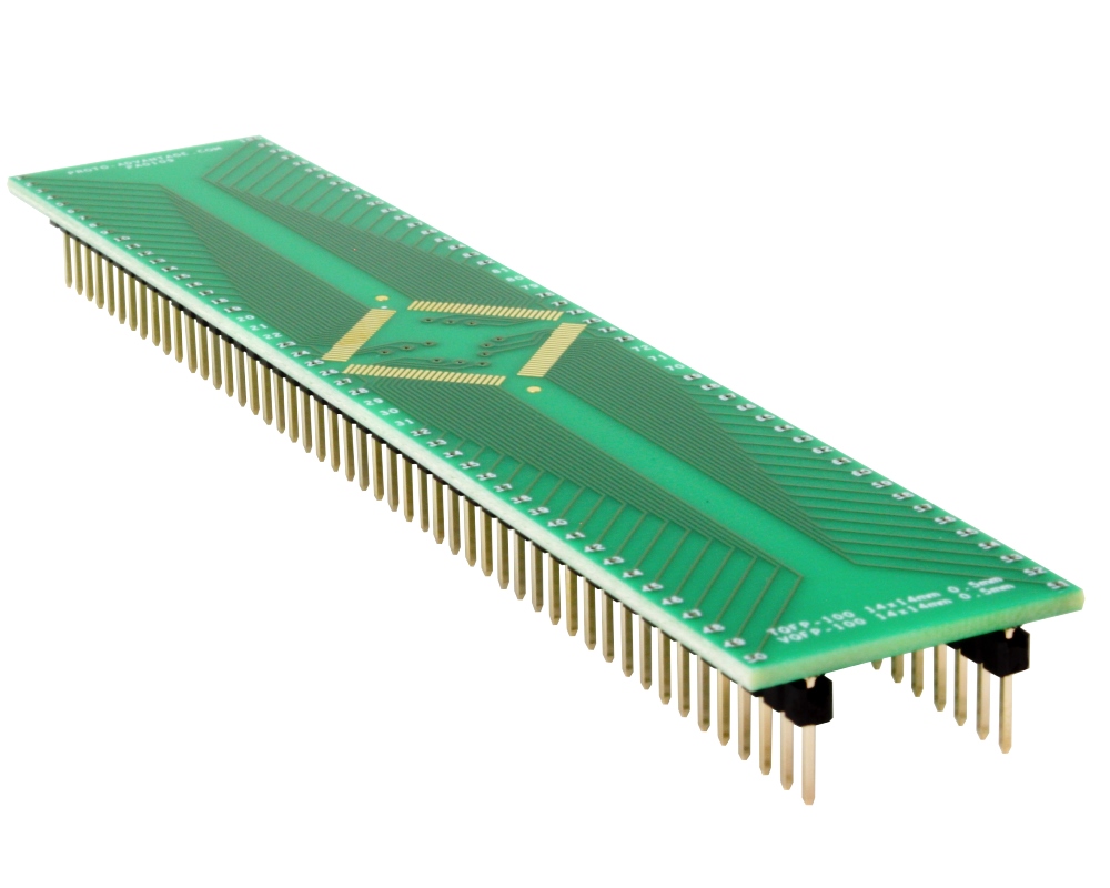
I was disappointed that even the Propeller took that route. You can get the Propeller 1 as a 40-pin DIP you can put directly on a breadboard for $11.19. But the Propeller 2 is only available as a 100-pin TQFP, and the "module" that contains the Propeller 2 is $79.00, which seems unreasonable. Even then, the module has a card-edge connector, so you can't put it directly on a breadboard.
(I never really got into the Propeller, in large part because its programming model is so different from anything else that it's nontrivial to migrate to. But it always seemed like a cool concept.)
snow light
river hatch
I was disappointed that even the Propeller took that route. You can get the Pro...

What an amazing adapter, it'll almost dwarf the breadboard!
river hatch
snow light
http://www.proto-advantage.com/store/images/PRODUCTS/PA0109_0.JPG
Yeah, although in fairness, their module is more than just an adapter. It has some supporting circuitry, and they also talk about it being a 6-layer PCB that's designed with noise and thermals in mind. I don't know if it would be possible to use a simple TQFP adapter board with the Propeller 2 or not.
snow light
river hatch
Yeah, although in fairness, their module is more than just an adapter. It has s...
Yeah, probably not- they support some pretty high-speed data on that thing. It's an amazing chip built from the ground-up, but I think it didn't catch on much for exactly the reason you described- thinking in terms of "cogs" is quite a paradigm shift
river hatch
I like the fact that some old-school microprocessors like the 6502 and the Z80 are still available today, and still available in a DIP package. Unfortunately, those old microprocessors require so much supporting circuitry that they're not really a competitive alternative to modern microcontrollers, even if you don't need much processing power.
hearty karma
I use those DIP breakout boards too

Not really that much supporting circuitry, especially if you get clever
violet torrent
river hatch
I like the fact that some old-school microprocessors like the 6502 and the Z80 a...
I purchased a Z80 a few months ago to play around with, cause it's such a well known chip
river hatch
violet torrent
I purchased a Z80 a few months ago to play around with, cause it's such a well k...
I grew up programming on the Apple //e (which had a 6502), so I'm partial to it. (Although I think that, objectively, the Z80 is a more powerful processor.) I still have the Apple //e and still write some code for it from time to time.
It would be fun to build some sort of project with a 6502 processor in it, but that requires ROM, RAM, IO, and address decoding logic. It's so much easier and cheaper to use a modern microcontroller instead.
violet torrent
I only got the Z80 because it was more available, I think I have a 6502 variant laying around already anyway. I'm planning on starting out the building with doing everything peripheral on a Pico or something similar, and slowly replacing the functionality with logic chips and other some such
supple crypt
river hatch
I noticed that Microchip's website now says that the ATmega328P is "Not Recommen...
If you haven't seen them, Adafruit make some little breakout boards for SMT chips that you can solder headers into: https://www.adafruit.com/category/475
river hatch
supple crypt
If you haven't seen them, Adafruit make some little breakout boards for SMT chip...
Yeah, I have a bunch of them. Hand-soldering SMT chips isn't too bad, as long as the pitch isn't too fine, and as long as it isn't a QFN. Still, DIP chips are nice because they're the easiest to solder, the easiest to breadboard, and they can be socketed.
supple crypt
Indeed
river hatch
I'm always amused by the photo for this breakout board, since it shows putting a TQFP-48 chip on a TQFP-32 breakout board.

Beguiled by a fancy new chip that is only available in a QFP or QFN pinout? This breakout PCB set will make your life much much easier and get you prototyping faster than ever. One side has ...
steady gulch
like a square peg in a... different square hole
violet torrent
On the topic of breadboarding from earlier, I was thinking of ways to make it easier for me, and a YouTuber I just found came up with the same solution I was thinking about for bussed lines
supple crypt
violet torrent
On the topic of breadboarding from earlier, I was thinking of ways to make it ea...

Was it this?
violet torrent
Using small PCBs to jumper the connections
regal horizon
I just made something similar. Using jumpers for connections too. Recently I’ve started seeing a lot of dev boards like that. When all you really want is a couple extra Gnd, 3v3 pins, or other data bus. if you can spin up a purpose built pcb it makes more sense.
hearty karma
violet torrent
I purchased a Z80 a few months ago to play around with, cause it's such a well k...
I'm playing around with an 1802, which came out at a similar time, although it's less well known, it's a really interesting chip. With its whopping 16 16-bit registers, it feels more like a RISC chip, and offers many features that didn't show up again until much later.
violet torrent
huh! nice!
violet torrent
violet torrent
I only got the Z80 because it was more available, I think I have a 6502 variant ...
Thinking about it, if I don't want a billion bidirectional logic level converters, I'd probably have to go with a 5V microcontroller, which ultimately probably means an Arduino Mega or Giga or smth
hearty karma
Same...
 violet torrent
oh well, that's not a huge issue
violet torrent
I should get my hands on some 5V MCU stuff for all of these TTL stuff
teal wadi
I guess you can get a bunch of atmega328p boards before the chips go eol
violet torrent
What boards use that one?
violet torrent
I have an Uno already I could use, just didn't think it has enough pins at the moment
bulk buys 328Ps
teal wadi
I mean, you probably do not want to drive the entire z80 out of an arduino
You're probably gonna get a mux to make a memory map (for the IC enable signals), an EEPROM to load the program, some SRAM, and then map some of the remaining memory space to the uno
regal horizon
the new Arduino Giga has some very impressive specs.
teal wadi
Maybe have a buffer in between too
violet torrent
The idea is to start with it being entirely run on an Arduino or similar, and then slowly replace functionality with ICs
regal horizon
violet torrent
The idea is to start with it being entirely run on an Arduino or similar, and th...
To some people that might seem like going backwards away from microcontrollers but that's actually how you learn the intricacies of IC's. It's a good plan. 👍
breakout boards for IC's is another good way to do it.
which is basically the premise of the original Arudino anyway. it's just a breakout board for the 328 😉
teal wadi
regal horizon
breakout boards for IC's is another good way to do it.
Thankfully, most ICs you'd need to make a Z80 computer are already in DIP form
Even though they're positively ancient, they're still in production
violet torrent
I have a lot of the chips I already will need, I think, but I mostly want a way to have a Known Working model
For example I have 100+ 4164 chips, and a fair number of EPROMs, and a bunch of 74 logic chips
Infinite RAM on the Z80 cackles
(jk they're still very small capacity, but at least they're basically what the Z80 was made to work with)
regal horizon
One thing I've learned from hanging out around here is that learning how things were done with some of the original PC's from the 70's, 80's, 90's can help to see how things have scaled up and changed. Taking a step backwards to go forwards kind of thing.
hearty karma
I'm working on a design that uses an FRAM chip as both the RAM and ROM to speed up updating as well as reduce total chip count.
regal horizon
Honestly didn't know what FRAM is. Looked it up. Seems like a neat concept using higher or lower logic voltages for different operations.
The farther back you go the more likely you're going to end up diving into assembly. That's where I draw the line, no thank you. 😛
violet torrent
I'm wanting to learn ASM and uCode
although, technically, uCode is very CPU dependant, but I've been watching a lot of CPU recreation videos lately
hearty karma
The computer I learned on didn't have enough RAM to run an assembler, so I'd write my code in assembly, hand-assemble it into machine code, and key the resulting hex into the computer to run it. Tedious but a great way to learn how everything works at a low level.
violet torrent
as much as that sounds like pain, it also kinda sounds like fun
I'd love to try it at some point
especially since I'm planning on adding a HEX programmer to the Vambrace
regal horizon
what is a dream to one is a nightmare to another. wish you the best.
hearty karma
There's a nice description here, using the same kind of computer I learned on http://roland.cordesses.free.fr/Motorola6800MEK_4.html
Although he shortchanges the RAM, maxed out with all six 6810 128B SRAM chips, it has a princely 768B, not 640.
teal wadi
violet torrent
although, technically, uCode is very CPU dependant, but I've been watching a lot...
you can learn microcode?! I thought that was internal to the CPU, and couldn't be used externally!
hearty karma
I did get spoiled learning on the 6800 with its two accumulators. Switching to the cheaper ($25 vs $300 when they were new) 6502 with its single accumulator was annoying.
teal wadi
(In case my tone doesn't work: I am genuinely surprised and curious)
teal wadi
hearty karma
I did get spoiled learning on the 6800 with its two accumulators. Switching to ...
...and now you can get a 70-cent ARM chip with hundreds of general-purpose registers
hearty karma
Yeah, it's nuts.
violet torrent
It's more if I plan to make my own CPU out of TTL chips, like the SAP or jam-1, or to emulate an existing CPU, like the 6502 and the Z80
teal wadi
....at that point, I'd recommend learning a HDL and synthesizing one inside an FPGA
hearty karma
Ben Eater's series on building a CPU on breadboards is fascinating (as is his series on building a simple 6502 computer on a breadboard)
violet torrent
That's the SAP I was referring to there, his is a variant of the SAP theoretical model
hearty karma
My picture above of my project breadboarding an 1802 CPU using an Arduino as a bus analyzer is heavily based on Ben's work
Ah, didn't realize that. Cool!
violet torrent
The jam-1 is really interesting because it does 8-bit pipeline!
regal horizon
Just saw in the newsletter the new challenger board https://ilabs.se/product/challenger-rp2040-uwb/
hearty karma
I do play with the idea of breadboarding a simple machine based on Motorola's unusual MC14500B 1-bit CPU
regal horizon
I think it's designed to do long distance measurement?
violet torrent
hearty karma
I do play with the idea of breadboarding a simple machine based on Motorola's un...
I think I've seen someone make a variant of that (or a different 1 bit Motorola CPU) out of vacuum tubes
regal horizon
with 2 static positions you could do triangulation on a 3rd. that sounds very neat. i don't have a use case for it but i want to find one. 😛
hearty karma
And one day, when I crave pain and suffering, I may try breadboarding an Intel 8008, crammed into its 18-pin DIP
violet torrent
violet torrent
I think I've seen someone make a variant of that (or a different 1 bit Motorola ...
It's a variant because I think they modified the ALU
Internal computer architecture is fascinating
hearty karma
The best I've built out of vacuum tubes are some flip-flops and counters.
violet torrent
https://youtube.com/@weirdboyjim for the jam-1 and https://youtube.com/@UsagiElectric for vacuum tube computer (and other vintage computer stuff, it's awesome)
teal wadi
hearty karma
The best I've built out of vacuum tubes are some flip-flops and counters.
Next thing we know, you'll have built an EDVAC replica in your house
Fun fact: There's a gene that (used to be) named JAM-1
 teal wadi
icy moth
The music gene, or maybe it’s the gene to determines if you like berries or not?
teal wadi
icy moth
The music gene, or maybe it’s the gene to determines if you like berries or not?
Nah, it's a cell adhesion mediator. So you could say it jam-packs cells together
 violet torrent
jam-1 in the CPU sense is james' arithmetic machine, iirc
teal wadi
(It actually stands for Junctional Adhesion Molecule-1)
hearty karma
The folks here have some wide-ranging interests and knowledge!
regal horizon
That's what makes this place so awesome.
violet torrent
i love how y'all aren't dismissive of stuff i find cool, and are usually helpful when i have gaps in my understanding for electronics stuff
TIL pure Turing machines would probably be kinda slow
teal wadi
violet torrent
TIL pure Turing machines would probably be kinda slow
As far as the memory access model is concerned, loading data from tape would be the closest we have to what Alan Turing envisioned. That's... pretty slow indeed :P
Other than that, given they're all Turing complete, I'd say all computers are "pure Turing machines"
violet torrent
It's the memory access I'm thinking about mostly as what delineates Turing compatible with a "pure" Turing machine
teal wadi
Yeah, that makes sense
supple crypt
To come back to this, I'm still thrown by how this would explain the difference. Obviously yeah, power = voltage * current, but the gap still seems utterly huge for what isn't even double the voltage.
2.5V * 0.035uA = 0.09
3.3V * 20uA = 66
hearty karma
That's only for ohmic loads: semiconductors famously have a non-linear response to voltage.
supple crypt
checks their IMDB
This is from the chip datasheet: https://www.ti.com/lit/ds/symlink/tpl5110.pdf
 hearty karma
Something else is going on. Have you tried measuring it?
supple crypt
hearty karma
Something else is going on. Have you tried measuring it?
I haven't bought either yet partly because of this heh
hearty karma
I'm still leaning toward things being specified in different ways.
supple crypt
Should the extra components it's combined with be increasing the current a lot? It seems like Sparkfun used the current number from the datasheet and Adafruit have measured their board's total consumption
hearty karma
I haven't looked at the schematics of either board, so I can't say.
supple crypt
Adafruit: https://cdn-learn.adafruit.com/assets/assets/000/039/783/original/adafruit_products_schem.png?1488404279
Sparkfun: https://cdn.sparkfun.com/assets/a/8/0/9/1/SparkFun_TPL5110_Nano_Power_Switch.pdf
 hearty karma
The two schematics look equivalent, I don't see other parts that would be affecting the current draw.
teal wadi
(Offtopic? )Question: Which software do IC corpos use to make their datasheets?
Or do they straight-up just use MS word?
supple crypt
teal wadi
(Offtopic? )Question: Which software do IC corpos use to make their datasheets?
I assume that'd vary a lot from company to company, though I'd imagine most have some kind of template they use
supple crypt
supple crypt
This is from the chip datasheet: https://www.ti.com/lit/ds/symlink/tpl5110.pdf
The metadata for this TI datasheet says it was produced by https://turnkey.com.au/topleaf/ and iText
supple crypt
My Sensirion ones are actually made in Word, with my Espressif ones using LaTeX with hyperref
teal wadi
supple crypt
My Sensirion ones are actually made in Word, with my Espressif ones using LaTeX ...
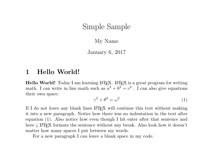
Can you link to said espressif datasheet? I really want to see what LaTeX can do in this context
supple crypt
teal wadi
Can you link to said espressif datasheet? I really want to see what LaTeX can do...
teal wadi
O_O It doesn't look like LaTeX at all haha
I'm used to them looking like this
https://s3.amazonaws.com/libapps/accounts/109251/images/Screen_Shot_2017-01-06_at_4.18.48_PM.png
 supple crypt
I thought the whole thing with LaTeX was that you can do very fancy things with it
inner linden
Yes, the big appeal of LaTeX is... brace yourself... equations.
teal wadi
inner linden
Yes, the big appeal of LaTeX is... brace yourself... equations.
- Nice pun
- TBH, the math rendering in LaTeX is superb
jaunty socket
is gpt-j of any use for finding information?
like would it tell me what part to use to do X on an Arduino?
does this looks dangerous? sure does to me
 river hatch
violet torrent
Thinking about it, if I don't want a billion bidirectional logic level converter...
river hatch
violet torrent
Thinking about it, if I don't want a billion bidirectional logic level converter...
Another microcontroller that can run at 5V is the ATSAMC series of ARM microcontrollers from Microchip. They are very similar to the ATSAMD series, which only run at 3.3V. Strangely, there are tons and tons of boards for the ATSAMD, but virtually none for the ATSAMC. I would have thought that the ATSAMC would be more popular among makers, since it can run at 5V.
I've been meaning to play around with the ATSAMC (by putting it on one of those generic SMT breakout boards we talked about, and then breadboarding it) but I haven't gotten around to it yet.
snow light
river hatch
Another microcontroller that can run at 5V is the ATSAMC series of ARM microcont...
Cypress PSoC5 is 3.3v but can run at least half of its I/O at another voltage. They're sadly stupid expensive/unobtanium right now tho
river hatch
jaunty socket
does this looks dangerous? sure does to me
400W is a small space heater, so you could definitely start a fire with that. 60V would give you a nice jolt, but I don't know how likely it is to be lethal. (My guess would be "usually not", unless you have a pacemaker or something.) Normally I think 48V is considered the cutoff for "safe" low voltage.
jaunty socket
That was my impression, cheap, but it's not for the beginner and they expect you to know what to do about it
Also giving 10 to 24V to it doesn't seem beginner level either and not very standard
My impression is that they sell bare-bones stuff without handholding or nice to have features like adafruit
river hatch
jaunty socket
My impression is that they sell bare-bones stuff without handholding or nice to ...
Yeah, I'm not familiar with that website, but generally Adafruit and Sparkfun are going to be more beginner-friendly.
12V and 24V are pretty much the standard for LED strips. (12V is most common, but 24V is not uncommon.)
jaunty socket
not just beginner-friendly but well designed
It's like paying a friend who build pcs for a living
and then they move to another country and you lose contact with them. Something break and you look at a youtube tutorial
And everything is labeled, at the correct place, without any weird choices (like using 4 IDE instead of two PCIE) etc
I try to explain the adafruit advantage to peoples sometimes but I just can't find the right words because "it just works as it's supposed to" is meaningless for total beginner
supple crypt
jaunty socket
does this looks dangerous? sure does to me
I was going to post a link to a 3.7-6V -> 400KV module I stumbled on recently, but I remembered the Adafruit Discord has some rules about not posting likely dangerous stuff
supple crypt
river hatch
400W is a small space heater, so you could definitely start a fire with that. 6...
Unless I've misunderstood it, surely the 400W is going to be what it can supply to connected stuff? Though yeah, 60V is a bit high.
jaunty socket
dangerous ? I mean P still equal V*I or that changed ?
I hope P is still V*I dont want to relearn all of this


 jaunty socket
My point anyway is if you mutiply the voltage by 100000
to keep the same power you divide the amp by 100000
So it's like having an hose connected to the ocean instead of a pond
but the output is 100000 smaller than before
so actually one drop comes out every century vs before
isnt that concept called van de graaf generator anyway ? 😄
that is inoffensive afaik since they let preschoolers touch them
river hatch
supple crypt
Unless I've misunderstood it, surely the 400W is going to be what it can supply ...
Yeah, it can supply up to 400W. I'm just saying that if you have a short, or if your wire gauge is too small, that's a lot of power that can produce a lot of heat.
jaunty socket
400W would be like 60V*6.5A or something, they say above 8A you need a fan/heatsink
wish they made leds you can power from your body static since they eat voltage
And 50000 V would be good for a lot of leds 🤣
river hatch
Yeah, fluorescent tubes are better for powering with a van de graaf generator, or by standing underneath power lines.
river hatch
jaunty socket
that is inoffensive afaik since they let preschoolers touch them
For the tabletop van de graaf generators, they let kids touch them. Although at the Boston Museum of Science, they have a room-sized van de graaf generator, and there the operator is inside a Faraday cage for protection.
jaunty socket
Yeah I love when they tell you it's not dangerous but the hospital machine is a lead bunker the furniture including the bathroom are all metal the examination room has a 12 inch thick door with a ship wheel lock and they stand in a room with 1 feet of rolled steel armor
Ill be radioactive for the next 299000 years because of this 😦
river hatch
Radiation therapy?
jaunty socket
They just wanted to make sure I didnt have something that would need that
but yeah diagnosis with radiation
random ravine
*grumble* Of course it works better when you plug it in *shrug*
jaunty socket
WHat is an adafruit Bluefruit S60 from 2013 ?
supple crypt
jaunty socket
WHat is an adafruit Bluefruit S60 from 2013 ?
..are we playing Jeopardy?
jaunty socket
no, adafruit posted that product for FCC approval in 2013
but surprisngly the schematic/pcb file isnt available
So I supposed it was before they were open source or something and it's like a discontinued antique
It's just so bizarre vs what adafruit usually fdo looks like an OEM product for integration in larger one
river hatch
jaunty socket
WHat is an adafruit Bluefruit S60 from 2013 ?
I did some Googling, and it looks like the Bluefruit S60 was also known as the Bluefruit EZ-Link, and was a module that was used in a couple of different products from Adafruit, now discontinued:
https://www.adafruit.com/product/1588
https://learn.adafruit.com/adafruit-bluefruit-ez-link-shield

We are excited to add another product to our growing Adafruit Bluefruit line, this time it's the Bluefruit EZ-Link: the best Bluetooth Serial Link device ever made. Like you, we have ...

Adafruit Learning System
Program & Communicate Arduinos over Bluetooth
hearty karma
In my experience, Bluetooth is never easy
river hatch
I'm contemplating a project where I would need to send a small amount of data (three bytes, maybe 60 times a second) from one point to another wirelessly. Right now I'm contemplating Bluetooth LE, RFM69, and XBee. Or possibly even infrared? (10-12 feet, line of sight) Not sure which is going to be best.
supple crypt
river hatch
I'm contemplating a project where I would need to send a small amount of data (t...
Wired or battery power?
woeful whale
or NRF24
jaunty socket
most important question is what happens if some of the data is wrong
if so you will need a crc and both ways communications
supple crypt
hearty karma
I haven't looked at the schematics of either board, so I can't say.
Just Googled and found some posts on the forum, seemingly it's down to the LED:
https://forums.adafruit.com/viewtopic.php?p=857793#p857793
regal horizon
Sounds like once per 16ms. Wifi would be the obvious choice. It can stream more data faster than bluetooth or rfm. Don't know about IR.
IR can pulse that fast with PWM but IR generally doesn't have CRC. Transmission time between packets is slow with the RFM because it switches between send or receive, not asynchronously, and enabling CRC slows it down even more. Wifi is the obvious choice.
RFM is good for projects that take seconds, not milliseconds, that's just my opinion from the behavior I experienced with it so far.
The timing window for RFM listening for a packet between sends I think would be too short. If you shorten the listen window too much it won't receive any packets.
 novel ridge
The ESP-NOW protocol could work if you're using microcontrollers in the ESP32 family. I've found it to be pretty fast and reliable, and it's fairly simple to use.
snow light
novel ridge
The ESP-NOW protocol could work if you're using microcontrollers in the ESP32 fa...
That works with the 8266 as well but I can’t remember if they’re interoperable
novel ridge
snow light
That works with the 8266 as well but I can’t remember if they’re interoperable
Oh looks like it is 😄 https://www.espressif.com/en/solutions/low-power-solutions/esp-now
ESP-NOW is a wireless communication protocol defined by Espressif, which enables the direct, quick and low-power control of smart devices, without the need of a router. ESP-NOW can work with Wi-Fi and Bluetooth LE, and supports the ESP8266, ESP32, ESP32-S and ESP32-C series of SoCs. It’s widely used in smart-home appliances, remote controlling, ...
snow light
novel ridge
Oh looks like it is 😄 https://www.espressif.com/en/solutions/low-power-solution...
Oh and it can do it over BLE too! That’s cool
river hatch
supple crypt
Wired or battery power?
Wired on the receive end. The transmit end could be either wired or battery, but if it's battery, then battery life/size isn't really an issue. Basically, power is not an issue.
supple crypt
river hatch
Wired on the receive end. The transmit end could be either wired or battery, bu...
I haven't tried ESP-NOW for such constant sends but it might work for that. I have some CP code you can play with if you've got a couple of ESP32 devices running CP, and we've got a thread for it in the #help-with-circuitpython channel.
river hatch
jaunty socket
if so you will need a crc and both ways communications
All I have is 16-17 bits of state on the transmitter, that I want to keep as up-to-date as possible on the receiver. Rounding up to 3 bytes gives me 7-8 bits of checksum, which is probably enough, although I could add another byte if necessary. Communication is strictly unidirectional. There is no point in retransmission, because the retransmitted data would be out of date, and the next scheduled transmission would bring the new data.
novel ridge
supple crypt
I haven't tried ESP-NOW for such constant sends but it might work for that. I ha...
Oh cool, I didn't know it was implemented in CP!
supple crypt
river hatch
All I have is 16-17 bits of state on the transmitter, that I want to keep as up-...
Yeah I think this might work okay for you, though my understanding of what bits equate to is limited especially when I probably should sleep
supple crypt
novel ridge
Oh cool, I didn't know it was implemented in CP!
Yeah, pretty recently, but my testing so far indicates that using it with another device acting as a full WiFi relay, it should improve IoT sensor node battery life by 4-5x or more.
cold pebble
ESP-NPOW packets can be up to 250 bytes, and you could split longer messages across multiple packets
supple crypt
Sure you could buy a huge lithium ion battery pack for each node, or you could buy a QT Py ESP32S2 and plug it into USB, and then use 3 x 2000mAh NiMHs and a TPL5110 timer and get around 215 days of battery life (readings every 5 minutes).
river hatch
regal horizon
Sounds like once per 16ms. Wifi would be the obvious choice. It can stream more...
I've just had bad luck with using WiFi for real-time applications. WiFi is great most of the time, but then it will go out to lunch for a second or two, or sometimes it will disconnect entirely, and require a power cycle to reconnect.
I could tolerate 50% packet loss if it was random, but losing connectivity for a second or more would be a serious problem.
supple crypt
river hatch
I've just had bad luck with using WiFi for real-time applications. WiFi is grea...
Yeah, it's not proper WiFi is the thing, no router needed.
cold pebble
ESP-NOW doesn't connect to an AP, it just blurts out a packet, and the receiver listens for it
supple crypt
I think it somewhat borrows some WiFi things internally, but it doesn't work on connections, just yeah, it basically just yells out data
cold pebble
it's pretty speedy, the delivery confirmations come back in a couple milliseconds or usually less
river hatch
cold pebble
ESP-NOW doesn't connect to an AP, it just blurts out a packet, and the receiver ...
Yeah, that sounds more like what I need. But was responding to DJDevon3, who I think was suggesting proper WiFi?
supple crypt
ahh sorry, very much need to sleep
river hatch
Good night!
supple crypt
but also need to decide on things to order haha
Why can't Pimoroni just have all the things I want in stock, darn pirate ninjas..
here's my super simple sending code, would have deep sleep if I wasn't just using it to test the receiver code right now
My receive code is more complex because it's taking the data, grabbing the sensor values, then sending them to IO, but it does hopefully explain how to get the encryption/MAC address side of things set up, as ESP-NOW is a bit of a targeted yell of data.
Be aware it's a bit buggy right now and is only in the CP 8.1 beta, but I think there's a reasonable chance it might work for this. What's the data it's sending coming from?
river hatch
supple crypt
Be aware it's a bit buggy right now and is only in the CP 8.1 beta, but I think ...
Basically I have a wired game controller (from the 1980s era) and I want to make it wireless. So the state is just a matter of what buttons are pressed. Needs to be pretty responsive, or the game will be unplayable.
novel ridge
I literally just used ESP-NOW for this exact purpose a few days ago lol
it worked great
supple crypt
Nice, I wasn't sure about the latency
cold pebble
@novel ridge what packet rates are you achieving? at what wifi speed?
novel ridge
cold pebble
<@338136878828224512> what packet rates are you achieving? at what wifi speed?
Those are great questions, that I don't know the answers to!
cold pebble
I'm doing ACKs, so each node sends and receives, which complicates things
novel ridge
Ah yes, that would. I'm only sending very small packets (on button press/release, and when a rotary encoder's value changes) and it's not catastrophic if one is missed, though anecdotally I haven't had any issues with missed packeets
cold pebble
I think there's a bug (hopkapi discovered), you can only set rate up to 36Mbps, but should be able to go to 54Mbps, though I don't know if rate affects error rates
novel ridge
Oh that's interesting. I didn't realize that was something that was adjustable
I just used a modification of one of the ESP-NOW examples in Arduino lol
cold pebble
you can collect send and read stats (send success and failure counts, and read success and failure counts print(f"send=[{e.send_success} {e.send_failure}] read=[{e.read_success} {e.read_failure}]")), but there is a slight delay (microseconds to a couple of milliseconds) before the data is available on send https://gist.github.com/anecdata/f46a1d07add5fc60cfbcf42dc7be6528?permalink_comment_id=4524207#gistcomment-4524207
ah, Arduino, same concept though
novel ridge
Oh yeah I see what you did there
cold pebble
if wifi rate isn't specified, it will be 1Mbps
novel ridge
(sorry I am on my Macbook wiith the terrible butterefly keyswitches lol, hence the typos)
supple crypt
Just had a thought, do you think I could solder lil' 2.54mm terminal blocks onto this breakout board? Not sure if it'd fit, but I'd rather not have to breadboard + jumper everything.https://www.adafruit.com/product/3435
river hatch
Probably? I guess you'd just have to try it to see if the terminal blocks fit.
supple crypt
I think they'd fit horizontally but not sure if there's enough space the other way hmmm
I guess otherwise I could solder wires to the vias but not sure how well that'd go/how durable it'd be hmmm
river hatch
Looks like the 5-pin 2.54mm terminal block is out of stock right now:
https://www.adafruit.com/product/2139

After a long day out harvesting in the terminal block fields, we've returned with a veritable bounty of these very nice and compact 2.54mm/0.1" terminal blocks in a variety of ...
supple crypt
river hatch
Looks like the 5-pin 2.54mm terminal block is out of stock right now:
https://ww...
Yeah, I'm not in the US so I think I'd have to get 2 of the 2 terminal ones (I don't need the delay pin): https://coolcomponents.co.uk/products/screw-terminals-2-54mm-pitch-2-pin?_pos=5&_sid=49d808309&_ss=r

Cool Components
DESCRIPTION These are simple 2-position screw terminals with 2.54mm pitch pins. Rated up to 150V @ 6A, this terminal can accept 30 to 18AWG wire. The 2.54mm pitch will line up with standard 0.1" perf boards. RESOURCES Datasheet
cold pebble
they won't fit side-by-side, like 3+2≠5
supple crypt
dreams of WAGO PCB terminal blocks
supple crypt
cold pebble
they won't fit side-by-side, like 3+2≠5
Nope, but with a spare pin in the middle, that shouldn't be an issue
river hatch
supple crypt
I guess otherwise I could solder wires to the vias but not sure how well that'd ...
I've done that sort of thing before. It's considered "less professional", but I haven't had any problem with it. I recommend using wire with silicone insulation. (Otherwise, the soldering iron burns off some of the insulation, which might make it more likely to short if the wires are jerked around at weird angles.)
supple crypt
river hatch
I've done that sort of thing before. It's considered "less professional", but I...
Yeah I'm a big silicone wire fan, though I wish the main makery stores in the UK would sell it and not just in super super thin kinds
So looking forward to the EU banning PVC
river hatch
I've found Amazon and AliExpress to be good sources for silicone wire.
The only thing I don't like about silicone wire is that it only comes in stranded wire. Sometimes I would like solid-core silicone wire, but I don't think it exists.
supple crypt
river hatch
I've found Amazon and AliExpress to be good sources for silicone wire.
The only...
The Great Search music plays
supple crypt
river hatch
I've done that sort of thing before. It's considered "less professional", but I...
I guess I'm unsure about the strain relief side of things and how it's actually held in place. I dealt with that with my QT Py by just covering the two wires on the bottom with a blob of Blu-tack.
river hatch
supple crypt
I guess I'm unsure about the strain relief side of things and how it's actually ...
Solder alone can be pretty strong, although I haven't tried jerking the wires too hard, either. It probably depends on how much stress it's going to be subjected to.
supple crypt
I mean hopefully not much...
but I'd like proper wires because they're so easy to work with for different stuff, especially with WAGOs (221 inlines are love/life)
violet torrent
should have added a rotary encoder to this board but eh, hindsight
rugged field
i just got the DVI RP2040 Feather, the Proto Board Feather and some much needed storage boxes!
violet torrent
violet torrent
Thinking about it, if I don't want a billion bidirectional logic level converter...
Immediately I get a Hackaday article saying: You technically can use a Pico for 5V stuff
(it's not the best idea but you can)
teal wadi
violet torrent
Immediately I get a Hackaday article saying: You technically can use a Pico for ...
It's funny how these things progress though -- when I was doing microcontroller stuff a few years ago, 5V was the standard. It seems the community has moved on to lower voltages now
snow light
violet torrent
Immediately I get a Hackaday article saying: You technically can use a Pico for ...
The I/O on ESP8266 and ESP32 are apparently 5V tolerant too, but they said they took that out of the datasheet because people kept trying to power them with 5V and were blowing them up 🙄
regal horizon
I think a lot of that is actually determined by the chip manufacturers. Engineers can only roll out designs with existing chips. Adafruit is definitely responsible for making 3.3V logic popular, and in turn more chip manufacturers started creating 3.3V level chips from their 5V designs.
Some of the first LED strips were 12V. Going from 5V logic to 12V isn't a big leap, it's harder with 3.3V to 12V.
Then they came out with 5V LED strips which made it easier.
There were a variety of factors. Today 3.3V is easiest to work with due to I2C/SPI chip compatibility but since LED strips and some sensors are designed for 5V there's still a place for 5V boards.
The Qt Py and Scorpio for example can do 5V. Right tool for the right job. Now there is a huge lineup of boards. You can find one for almost any project goal you have in mind.
delicate quarry
regal horizon
I think a lot of that is actually determined by the chip manufacturers. Enginee...
Saying adafruit popularized 3.3v logic is giving Adafruit too much credit, in my opinion. The reduction of logic level voltage simply follows the trends and development of semiconductor manufacturing. As chip density increased to meet demand for more logic in smaller packages, the reduction in logic voltage was a natural response to concerns regarding heat dissipation and switching speed.
hearty karma
Many chips include protection diodes on the data pins, connected to the supply voltage. So if inputs are more than a diode drop above the supply voltage, the diodes try to clamp it. Making inputs 5V tolerant requires extra effort.
I would like to figure out how to use a 3.3V FPGA with 5V logic, which is likely going to involve level shifters, along with extra FPGA pins and logic to drive the direction inputs to the shifters.
regal horizon
I honestly believe Adafruit did actually help drive most of the microcontroller industry to 3v3 logic. I'm not saying they're the only reason. I'm saying they made it popular. Adafruit does set trends. Neopixels is a popular term now for example. Other manufacturers are using the feather format.
river hatch
hearty karma
I would like to figure out how to use a 3.3V FPGA with 5V logic, which is likely...
Yeah, I really wish there were FPGAs with 5V IO. It would make it so much easier to use FPGAs in retrocomputing projects.
hearty karma
Agreed. While there are 5V CPLDs available, they are sometimes not capacious enough. I'm toying with the idea of making an FPGA board with on-board level shifters and a DIP pinout for breadboarding/retrocomputing purposes.
If you count that as a "chip", it would be simple enough to build a 3-chip computer. If that computer were 1802 based, it could leverage the 1802's DMA capabilities to produce black and white video by just adding a counter, latch, and lookup table (all of which could fit easily in an FPGA)
delicate quarry
Ah, in that case, sure. There were a lot of other microcontrollers and maker-focused hardware that contributed to that shift, and I’d argue STM32 was probably one of the first with their discovery boards.
jaunty socket
Ive seen books saying that 3.3 and 5 were standard logic voltage from way before adafruit
river hatch
hearty karma
Agreed. While there are 5V CPLDs available, they are sometimes not capacious en...
Yeah, I should probably look into CPLDs. I haven't really seen CPLD breakout boards the way I have seen FPGA boards (such as TinyFPGA BX). And although some FPGAs have open-source toolchains, I think all CPLD toolchains are closed-source? (Neither of these are deal-breakers, but they are a couple of reasons CPLDs haven't been on my radar as much.)
snow light
river hatch
Yeah, I should probably look into CPLDs. I haven't really seen CPLD breakout bo...
As a software engineer I found it difficult to get started with FPGAs and CPLDs. The Cypress PSoC5 is an ARM microcontroller with a small CPLD on-board, and their tools make it really easy to integrate the two. Their IDE is, sadly, closed-source and Windows-only, but I found it quite nice and intuitive. (I promise I don't work for Cypress, I just found their stuff pretty easy to get started with)
jaunty socket
one example i quickly found 2003 PIC 16F628 is 3.3V
that imply there are 3.3V PLCs that support it and adafruit was founded in 2008
river hatch
snow light
As a software engineer I found it difficult to get started with FPGAs and CPLDs....
I found the TinyFPGA BX to be fairly easy to get started with, at least in terms of tools. The one thing that was difficult about getting the TinyFPGA BX up and running is that it wasn't compatible with my computer's USB port. I had to insert a hub in between to get the TinyFPGA BX to work.
river hatch
jaunty socket
that imply there are 3.3V PLCs that support it and adafruit was founded in 2008
I don't think anyone was claiming that Adafruit invented 3.3V logic levels. I think the question was just to what degree they contributed to the shift from 5V to 3.3V as the predominant logic level for maker projects.
In many ways, the industry has already moved on to 1.8V logic levels, but we don't see that showing up in the maker space yet.
jaunty socket
djdevon straight up said a major reason for it was adafruit
also dont forget the industry is also plcs and the military stuff most of us will never see
and our tiny hobby market gets the worst ancient stuff
that is why one cant get a pi4 for instance...
river hatch
The general chip shortage is why one can't get a Pi4.
jaunty socket
or you cant get a cell phone sized amoled because 15 million $ minimum order
so we just get surplus nobody cares about at the bottom of the pile
snow light
river hatch
I found the TinyFPGA BX to be fairly easy to get started with, at least in terms...
Ah yeah, I've had to do that too- I have a couple USB2 hubs sitting around for that exact purpose. I'll have to check out the TinyFPGA, they look neat
jaunty socket
iif it actually become available like drones and radios they do a tons of laws so muggles cant actually use it
stay where you belong with your 1W radio or face 10 years in jail
but if you have a company feel free to use the 500W ones
teal wadi
native hare
what the benefit of lower voltage
Well, one factor is that (assuming Ohm's law, which is a pretty big assumption) P (power)=V**2/R, so the lower the voltage, the lower the heat dissipation and power consumption. Hem also talked about switching speed, and I'll admit I'm not knowledgeable enough to discuss that
hearty karma
river hatch
Yeah, I should probably look into CPLDs. I haven't really seen CPLD breakout bo...
You're right there. I bought some surplus 5V CPLDs on the cheap, but have been unable to use them as there is not a toolchain available.
jaunty socket
but that comes at a cost too
lower voltage = cant tolerate as many voltage droppers
5V cost is already that it cant move more than 1 servo directly
hearty karma
native hare
what the benefit of lower voltage
Basically it's possible to make smaller, faster, and more power efficient chips with lower voltage.
jaunty socket
lower voltage usually have more issues with noise
if you are going to use a couple of transistors 3.3v wont do either
a lot of them drop 0.5/0.7V and now you have 2.8V for the rest
good luck if you add a diode and a led...
hearty karma
While it can be tricky to properly switch MOSFETs with 3.3V, there are logic level MOSFETs available. And 3.3V is plenty for a bipolar transistor, even the 1.4V double B-E drop of a Darlington pair.
On the upside, you can tolerate a lot of voltage drops on the power supply side, which is handy.
jaunty socket
npn type bipolar silicone transistor
also in some era it seemed the way to solve any problems was to pump as much voltage in it as possible
audio not clear enough? no problem out 1600V in it!!!
hearty karma
My vacuum tube circuits generally run on a few hundred volts and the audio does sound amazing.
jaunty socket
is there an electronic tester that would tell me if id get a dangerous shock touching something or the metal case or something?
cause i was told before that measuring continuity or voltage was not a proper method for that
would be ideal if past a certain number it just showed a skull
main hemlock
rev 5v vs 3.3v: I think it is interesting that Arduino is touting the Arduino R4 as being 5V. The Renesas chip on the board is 5v, but is very similar in spec to a SAMD21 (which is 3.3V, as we know). Arduino has had the Arduino Zero for years but apparently does not see it as the follow-on to the classic Arduino. And there are also availability and maybe subsidy considerations here.
main hemlock
jaunty socket
is there an electronic tester that would tell me if id get a dangerous shock tou...
you could measure DC or AC voltage between the thing and some ground, not sure why someone told you measuring voltage was "not proper"
hearty karma
jaunty socket
is there an electronic tester that would tell me if id get a dangerous shock tou...
Yes, they're called "non contact voltage testers" and the like.
main hemlock
typically (only?) for AC, right?
hearty karma
Right. DC ones are available, but less common.
jaunty socket
main hemlock
you could measure DC or AC voltage between the thing and some ground, not sure w...
i have an alarm clock that buzz connected to main and i tried to use a continuity tester on each butto. and the screen to see if id get a shock touching any of them
and was told without one of the probe touching the mains my test was useless 😦
i usually grab it by the screen & buttons on top
main hemlock
you don't want to use a continuity tester on a powered thing.
but I would think the buttons are plastic
does it work at all?
jaunty socket
yeah but part of my finger go a bit inside in the bottom of the button
main hemlock
the buzzing could be due to a failed capacitor inside, or the transformer (if it has one) becoming delaminated, or other reasons.
jaunty socket
and there could be enough voltage to spark at the bottom and give me a huge shock
not sure if its a buzzing or vibration very hard to tell
main hemlock
i haven't seen a metal cased alarm clock in a very long time
jaunty socket
but its strongest where the power cord plug internally
no it is plastic
but enough voltage can go throught the plastic
like when a multimeter blows up despite being isolated
main hemlock
it is not going to give you a shock unless there are metal exposed parts.
the plastic should be thick enough to protect against mains voltage
jaunty socket
i get a shock daily from my light switch because of this
..
why wouldnt my alarm clock shock me throught the plastic too?
jaunty socket
but only happen at the bottom of the light switch when its going down to the off position and my finger touch the metal at the base of the switch from the enclosure
it even sparks sometimes
main hemlock
I think you should replace that switch or check the wiring
jaunty socket
all light switches i ever used do this...
im just very static i guess...
happens mostly at the end of the day rarely in the morning
anyway this is what i fear when i touch my alarm clock buttons or glass
hearty karma
I used to carry around an NE-2 to discharge static with a pleasant little flash of light.
jaunty socket
i was using a cellphone once and touched the bus metal pole where you hold yourself and the cell phone went off immediately and wouldnt power on for a good 20 minutes i guess im very static...
ok 😦 i guess i should go to a science museum and try a van de graaf generator thing if it blows up ill know the problem is me
river hatch
hearty karma
You're right there. I bought some surplus 5V CPLDs on the cheap, but have been ...
I guess there are four levels of toolchain, from worst to best:
- No toolchain is available at all
- Toolchain costs money
- Toolchain is "free as in beer" (gratis)
- Toolchain is open source (libre)
and then a separate dimension is which platforms it is available for. (I could run the toolchain in a Windows VM, but it would be preferable to run it natively on Linux.) I guess that's one reason I prefer an open source toolchain, besides just for its own sake: open source toolchains are more likely to be cross-platform.
jaunty socket
For me it's very similar but I'd say he biggest criteria is if I can easily carry it on my raspberry pi 4 because a laptop is too big to carry/use in most makerspace I go too.
 gloomy mango
Get a ThinkPad X220/X230.. Small, light.. enough power to get the job done.
jaunty socket
Yeah it's that simple money grows on trees...
gloomy mango
Well, yeah.... It does, mostly. 😛
jaunty socket
spent 600$ on electronics including 50$ of lost components. If I bought a 1300$ laptop just for this I'd spend more on electronics than I have spent so far in my life
gloomy mango
The cotton plant isn't so much of a tree, but it's pretty close. 😄
jaunty socket
And it would still probably not run the windows-only tools properly
gloomy mango
Hang on
jaunty socket
money been made of plastic/textiles for a while
gloomy mango
Where do you get $1300 for an X220/X230 ?
I paid £95 (inc shipping) for an X220t.
blinks
jaunty socket
oh lol didnt notice the cnet article was from 2012
gloomy mango
Yuh huh........ lol
jaunty socket
I already have a 2012 laptop that is the problem
too big and only 4GB of ram
can only extended it to 8GB
Tried to install windows 10 on it and got death threats from microsoft
gloomy mango
Client: HexChat 2.16.0 • OS: LinuxMint "vera" 21.1 • CPU: Intel(R) Core(TM) i5-2520M CPU @ 2.50GHz (2.29GHz) • Memory: Physical: 7.4 GiB Total (4.9 GiB Free) Swap: 957.0 MiB Total (957.0 MiB Free) • Storage: 35.0 GB / 228.6 GB (193.6 GB Free) • VGA: Intel Corporation 2nd Generation Core Processor Family Integrated Graphics Controller @ Intel Corporation 2nd Generation Core Processor Family DRAM Controller • Uptime: 3d 1h 35m 11s
Huummm.. Missing some disk space. 😛
Local Storage: total: 1.13 TiB used: 49.43 GiB (4.3%)
ID-1: /dev/sda vendor: Seagate model: ST1000LM035-1RK172 size: 931.51 GiB
ID-2: /dev/sdb model: SSDSC2BB120G7R size: 111.79 GiB
ID-3: /dev/sdc vendor: Kingston model: SMS200S3120G size: 111.79 GiB
That's better.
jaunty socket
mostly would need to run fritzing/solidworks and eagle
1st priority would be solidworks
gloomy mango
I have no idea about any of those.
jaunty socket
but even my hard-core gaming pc isnt specced enough for solidworks so I doubt a 2012 laptop will do
gloomy mango
Not my bag
Yeah... having a definitive purpose for the machine does help guide towards an acceptable spec.
For me, I just need a Linux machine that can do the usual desktop Linux junk and run simple VMs.
gloomy mango
I could try it out on my server, with 80GB RAM.... but if it means installing Windows, I'll have to pass. 😛
river hatch
jaunty socket
spent 600$ on electronics including 50$ of lost components. If I bought a 1300$ ...
One time, I asked Digi-Key for a spreadsheet of all the parts I'd purchased over a 5-year period. The grand total was $4438.01. That's not even all my Digi-Key purchases, since I've been buying for more than 5 years. And it doesn't count what I've spent at Adafruit, Sparkfun, Mouser, or others. Electronics is an expensive hobby!
jaunty socket
yeah , but I dont really want to spend (expect to make enclosures/casings with solidworks) because I feel I dont have enough enough knowledge for the more expensive things
Like an fpga they are cool but unless Ive been using an emulator for a year I cant justify getting one
gloomy mango
FPGA can be pretty cheap.. if you want one to run, like.. a Z80 core. 😛
jaunty socket
In the expensive things though Id probably get a flir lepton with a flir board before any of this since I always wanted to see things my eyes cant see
or a chip used for microscopes
where as an fpga seems more useful for peoples like fermi or newton or the curies etc
gloomy mango
I do have a cheapo FPGA.. which would run a Z80, or 8086.
Just never got around to using it.
#lazy
jaunty socket
I mean like they seem useful for a lot of calculation
teal wadi
gloomy mango
Client: HexChat 2.16.0 • OS: LinuxMint "vera" 21.1 • CPU: Intel(R) Core(TM) i5-2...
Client: HexChat 2.16.0
👀
jaunty socket
but Im not much of a math/hard science person
teal wadi
Can you actually connect to discord over IRC?
jaunty socket
no
there's no irc anywhere in discord it's custom propriertary system
but fun fact gamespy app chat had irc in it back then
teal wadi
I wouldn't be surprised if there's some sort of unofficial bridge somewhere somehow
jaunty socket
they would get so annoyed when I used mirc to connect to it after I sniffed the server adress packets 😄
gloomy mango
teal wadi
Can you actually connect to discord over IRC?
I'm using IRC on my laptop, so easy copy/paste.
jaunty socket
Or to put it in a nice way. Discord is kinda irc without being slapped a bit with a large trout and without ctcps version 🤣
random ravine
There's an IRC bridge for almost everything.
gloomy mango
You can easily bridge IRC to Discord.. Pine64 does it.
random ravine

2078: He announces that he's finally making the jump from screen+irssi to tmux+weechat.
teal wadi
gloomy mango
I'm using IRC on my laptop, so easy copy/paste.
Ah, I see! If you don't mind me asking, which servers are you on? libera.chat?
gloomy mango
I'll be on IRC until I die, or it does.
teal wadi
I'm curious what the landscape looks like nowadays
gloomy mango
teal wadi
Ah, I see! If you don't mind me asking, which servers are you on? libera.chat?
Yup, Libera.. after Deadnode went and did the dead thing.
native hare
id still use IRC if anyone was on it
gloomy mango
Libera is still pretty busy.
jaunty socket
isnt freenode still full of peoples ?
teal wadi
freenode is dead afaik
gloomy mango
Deadnode is dead.
native hare
Freenode had ownership change I think
gloomy mango
Yes, stolen.
jaunty socket
was so much better when lilo was on it
gloomy mango
Lilo was displaced by grub. 😛
jaunty socket
no lilo the founder of linpeople which became freenode etc
gloomy mango
😄
jaunty socket
he died when coming back from a conference and being hit by a car
gloomy mango
Ouch
jaunty socket
and that irc network went downhill fast after that because of an admin succession war etc
gloomy mango
I just about recall lilo.
But, yeah... Deadnode is deader than a-line flairs with pockets in the knees.
Real shame.
*real sham.
jaunty socket
with lilo you knew what to expect but after with the various admins some were power trippy some had high tolerance you never knew
teal wadi
gloomy mango
Real shame.
Most of the communities migrated, didn't they?
jaunty socket
I remember that wikipedia channel said to not log the channel
so Id post an ascii of wood logs in a forest and got banned every so often 🤣
gloomy mango
teal wadi
Most of the communities migrated, didn't they?
Yes, rightly so.
gloomy mango
Ohh, I'm sure I've been on there more than a few times. 😛
random ravine
Try asking Marc not to log from their model 15. :)
jaunty socket
Wish that discord had something like *** kattni sets mode: +b MulhorandEmperor#1766*!@.*
gloomy mango
Safe travels! o/
jaunty socket
at least on irc we could says our last goodbye when being disciplined 🤣
gloomy mango
😛
So... back off work Sunday morning.
Think I might finally take the time to play with my server.
main hemlock
jaunty socket
im just very static i guess...
Sounds like your carpeting and maybe your insulating shoes 🙂
jaunty socket
Havent had a carpet for a milenia
because of the need for a hoover to clean it vs a cheap 5$ broom and a couple spray of cleaners
main hemlock
wool clothes?
outer brook
main hemlock
wool clothes?
Some times of the year I'm a better capacitor than others. Not sure why or if it's maybe in my head.
jaunty socket
I had to give away my cat once because of my static
I wrote about it before in here
gloomy mango
I once gave Beau a static shock to his nose.. He wouldn't come near me for hours. 😂
jaunty socket
yeah... same for mine but several accidental shocks even with sparks and my cat feared me more and more (even if cat fur is the biggest producer of static known in the universe - but try to explain that to a cat)
So it seemed best that I gave it a new life with another h00man and I gave it away
gloomy mango
Personally, I'd much rather solve the static issue.
jaunty socket
I couldn't find any reason for it, no carpet, I never used slippers, just electrical incompatibility I guess
gloomy mango
I get horrendous static charge when I wear my work boots.
jaunty socket
It was white and gray so I named it silver because I read a book about most common cat names and misread slippers as silver
I opened my defective headset but it was entombed in textiles and no external screws and inside it's a miniature 1975 style circuit
like I don't even think there is even a chip or a modern transistor in there
really weird
It's USB and they made it really durable so I'm at a loss to explain this
random ravine
I run a humidifier to reduce static issues.
jaunty socket
so that is why headset are 40$, 1970s tech inside the only circuit is a usb converter around a dime sized magnet and a coil of copper with around 10 windings around the copper "paper" around the magnet
not even caps for filtering
violet torrent
The multiplexed bar LEDs are cool but are really annoying to use
hearty karma
Which, like these? https://www.ebay.com/itm/154784514406

eBay
Find many great new & used options and get the best deals for 48seg 100mm LED Bar graph Full coLor Display (RGB) Common anode,can be spliced at the best online prices at eBay! Free shipping for many products!
violet torrent

Make a small linear display with multiple colors using this elegant bi-color LED bargraph. Only 1.2" long, it is quite visible but not so large it wont plug into a breadboard! 24 LEDs ...
apparently Adafruit has a backpack for it
hearty karma
That does simplify things, but you can also run them with a dozen I/O pins (or port expanders, shift registers, etc.) with current limiting resistors.
violet torrent
What I wish I could do is just... give it a 12 bit value, and a number from 0 to 3, and it gives me that 12 bit value on the LED
But I keep having issues wrapping my head around what logic I'd need for it
hearty karma
Jobs like that I like to push off to LED driver chips that take care of the multiplexing, timing, dimming, addressing, etc. for me
Basically if you were going to implement (PWM, there are other options) dimming with an MCU, you'd have one loop that scanned over the array and turned on the LEDs, then another loop within that that turned the individual LEDs off again after a time proportional to their desired brightness had elapsed.
 midnight mango
Does anyone here use the MHP30 mini hot plate, and would you mind popping the heater off and confirming the heating element resistance is not 0.3 Ohms? One GitHub issue says 5.6 Ohms but I want to double check.
I think mine shorted out after a single cycle… can’t find anywhere to buy a replacement either so maybe it’s just a pretty paperweight now.
verbal aspen
midnight mango
Does anyone here use the MHP30 mini hot plate, and would you mind popping the he...
The user manual says it runs on an 20V, 3A power supply, so I'm pretty sure 0.3 ohms wouldn't work well... it'd pull 60A at that voltage. I'd believe 5.6 ohms, give or take some PWMing and temperature-varying resistance.
midnight mango
Yeah for sure... I guess the question is more about replacement parts, but I'm just in denial that the thing died after one use. It was really handy for about 5 minutes.
woeful whale
Maybe you got a defective unit
Bc there's no way it would have shorted like that unless there is some defect
 leaden trout
I'm trying to figure out a control scheme for a John Deere turbocharger actuator. Pin out is 12v power, ground, 12v pwm, and a 5v "uart" pin.
12v PWM duty cycle controls the actuators rotation. I'm guessing the 5V uart relays information from the actuator... Perhaps reported position, faults etc
I have a logic analyzer arriving this weekend; any guesses as to what kind of communication protocol this 5V pin could use?
hearty karma
UART stands for "universal asynchronous receiver/transmitter", so likely asynchronous serial.
leaden trout
I thought UART was multiple pins?
Or wait I'm confusing that with the ol' serial plug
hearty karma
Yes, one of the most well known standards for serial data was RS-232, which specified a 25-pin connector. The later TIA-232 standard allowed a 9-pin connector as an alternate. However, serial data just needs two pins (signal and ground) for one-directional communication. My first computer actually uses 1/4 stereo phone jacks as serial connectors.
leaden trout
Haha that's pretty neat
I guess a case of retrofitting existing connection form factors for your application
I'm assuming this is one direction since the actual control signal is the PWM (weird that it's 12V instead of 5v). I've heard of a "calibration procedure" but I'm assuming that takes place in the John Deere ECU where it compares the commanded position with what the controller is reporting over UART
hearty karma
It does seem an odd lashup.
lost lily
Is it almost always better to do high-side current sensing?
(I'm probably going to be using something like this: https://www.adafruit.com/product/4226)
verbal aspen
It's more convenient because you get a voltage measurement too, so you can calculate power easily.
hearty karma
I normally do low-side current sensing, as I don't need a floating amplifier and level translation.
regal horizon
If you combine EdKeyes and madbodgers responses they basically give you a pro/con for each use case scenario. Good stuff. 👍
supple crypt
lost lily
(I'm probably going to be using something like this: https://www.adafruit.com/pr...
Might have missed what you're using it for, though if it's just overall project power measurement, you might want to look at the PPK2
lost lily
Thanks for the suggestion, but I don't think I need something that overkill lol
(I'm trying to build a dc power supply basically, with screen and rotary encoders to adjust voltage and max current, etc. )
outer brook
The power of a motor is T * (omega). Is this a dot product?
verbal aspen
outer brook
The power of a motor is T * (omega). Is this a dot product?
Technically, yes, but something would be mechanically weird if torque and angular velocity were not parallel.
verbal aspen
In the opposite case you have a generator instead of a motor, yes.
lost lily
I'm trying to control resistance, and I found the AD5290. (https://www.analog.com/media/en/technical-documentation/data-sheets/AD5290.pdf) I'm trying to parse the datasheet and it says:
+20 V to +30 V single-supply operation
±10 V to ±15 V dual-supply operation
I'm only going to be controlling between 0-30V, so is it fine? It's going to be in "single-supply" mode since there aren't any negative voltages so will being lower than 20V work fine? I'm assuming it wouldn't break anything to go below 20V...
hearty karma
I believe that's referring to the supply voltage. The signal voltage should be able to range from the negative supply voltage to the positive supply voltage.
lost lily
That would make more sense lol
Thanks
Hopefully I don't end up breaking these as well >.> ($6.50 a piece 😬)
hearty karma
I still think there's an easier way, but I'm not sure what it is (my current guess is a hybrid voltage divider)
lost lily
I'm currently trying to control a voltage regulator which uses a potentiometer in the feedback loop
supple crypt
Am I right to assume that other than the two connectors on the bottom of it and the Stemma QT port, the MagTag doesn't have any other pins you can use? Want to add a microphone of some kind to one and it seems like I'd need one that can work with the analog pin port. Kinda wish there was a Stemma QT mic that just did volume for this application.
violet torrent
There's also RX and TX
supple crypt
violet torrent
There's also RX and TX
Not sure that'd be useful for a microphone though?
violet torrent
Well, no, but they're available pins
hearty karma
lost lily
I'm currently trying to control a voltage regulator which uses a potentiometer i...
Yes, I remember. I'm wondering if you can simplify the implementation so you don't need a high voltage digital potentiometer.
lost lily
Its one of these things
I watched a great Scott video that used a hv digipot to control one of these, and in the comments some mentioned "injecting extra voltage" into the feedback line, which I have no clue how it would work. That will still probably require some sort of hv op amp?
 hearty karma
I doubt an op-amp is required, presumably the feedback pin only takes a low voltage (most chips use between 0.6 and 1.25 volts).
 simple pilot
Has anyone attached a bike wheel (quick release axel) to a stepper motor? I’d like to attach them together via the axel hole. I have an idea for an art project that I’d like to resuse some busted bike rims for but I don’t know how to adapt my stepper shaft to attach to the bike wheel.
hearty karma
I suspect with that much angular momentum, the stepper motor might have a hard time of it, but perhaps you could gear it down or something
lost lily
hearty karma
I doubt an op-amp is required, presumably the feedback pin only takes a low volt...
The voltage goes all the way to like 35v as it is a high voltage buck converter
woeful whale
lost lily
Its one of these things
I watched a great Scott video that used a hv digipot to ...
I think the method is that you have an extra resistor at the FB pin and then you use a DAC to vary the voltage on the other side of that resistor. The DAC is protected since it’s behind a resistor and the regulator wants to keep the FB pin at some voltage reference (like 1.25v or something?) (so no overvoltage into the DAC either). By changing the DAC’s voltage you change how the resistor divider works.
supple crypt
ooh, this is cool: https://www.youtube.com/watch?v=Vabq-s62IVM

This is a very intriguing device that uses a low current at low voltage to transfer moisture from inside an enclosure to the outside. Effectively a solid state dehumidifier with no moving parts.
The version I put in the box is a PD2 and is rated to remove up to 84mg of water a day, so really intended for small enclosures.
The large square unit ...
lost lily
woeful whale
I think the method is that you have an extra resistor at the FB pin and then you...
Ah, that's cool. Then I would need a hv dac or (or hv op amp in combination? Not sure how that would be wired up) either way lol to inject up to 30v
hearty karma
That's another valid approach, and easier to find parts for. And yes, you don't really need to generate 30V, you operate at the low voltage end of the divider.
woeful whale
I don't think you need to inject 30V. Just find some resistor values that work with a 3.3v DAC to give you the voltage range you need
I have no idea how you would calculate the values though
My approach would be educated trial and error
And that's obviously not the best approach
lost lily
I don't have the skills to reverse engineer the module, so I think it would be easier to control high voltage resistance
tbh, I was heavily considering using 7 relays and an IO expander and 7 values of resistors to control the resistance lol
Like I'll have 1k, 2k, 4k, 8k, 16k, 32k, 64k and wire them up in series, with the relays bypassing each resistor
But the 8-relay modules are huge and then I would need to obtain shift registers which I somehow do not have
Maybe transistors but the voltage drop is quite high for such an application
Possibly something like this? Would need 7 of these though https://electronics.stackexchange.com/a/146167/336339

Electrical Engineering Stack Exchange
I'm having an issue with a transistor.
I'm apply ~3.3v to the base, 4.7v to the collector, but only getting ~2.5v from the emitter. I need to be getting close to the full 4.7v I'm aware there is a...