#arma3_model
1 messages · Page 161 of 1
 woeful viper
 stuck oyster
😝
 runic plover
no, just play my mod and you can see some models which are done by me 
woeful viper
😄 reminds me of star citizen doors, hatches and chairs... that swing and swivel around like a rollercoaster, because they didnt think of enough space (or a proper mechanism) that can perform the action without it
stuck oyster
😛 really? 😄
im not too surprised though
I kinda wanted some fancy mechanics to it
woeful viper
its a pet peeve of mine.... terribly designed mechanisms
"if rotate isnt good enough, attach a ridulously long piston" -> thats the "answer" to all of star citizens door shortcomings
woeful viper
now for some inspiration - the smexiest door mechanism ever https://www.youtube.com/watch?v=MaP_qTppD_c (oh, and dont forget the sound...)
stuck oyster
oh yeah that is fine door
woeful viper
and a deceptively tricky mechanism to model (if you actually want to use real IK without cheating)
stuck oyster
I bet.
woeful viper
everyone who designs scifi vehicles should be obligated to take a course in mechanisms... and offroad mechanics. By law preferably
i always entertained the idea of dropping star citizen ground vehicles / lookalikes as mod into spintires/ mudrunner and have them compete in "who survives the longest" trials against high tech soviet trucks... from 1960 as video
woeful viper
too much work for the 2min video it would produce. The SC vehicles wouldnt make it 5m past the start line
 fluid loom
im running arma3p and getting this error: https://i.gyazo.com/c57b74434a5bc5b2b0cf0b5241910b4a.png
i reinstalled extractpbo and still getting the error
how could i fix this?
stuck oyster
you may need to set then windows environment PATH for the tools
I think there are instructions for that in the Mikero tools documentation or on BI forums maybe
woeful viper
i worked for a while on a highly mobile offroad vehicle platform (with SC in mind, but gave up on them) a couple years ago, Wouldnt be happening in SC anyway. They cant even get cargo ramps to work with non-testbox environments... Maybe one day ill finish it, i still quite like it. Maybe when my 40k mod is finished 😆 Only chance where the vehicle could technically be implemented right now is Mudrunner. Hopefully in Arma 4 it could shine too...
So here it goes, my single WIP for this year in this channel (i think) xD
https://abload.de/img/wip7_132k3u.jpg
https://abload.de/img/wip7_2zxk6k.jpg
https://abload.de/img/wip7_3hej1b.jpg
https://abload.de/img/wip6_28tkp8.jpg
https://abload.de/img/wip6_6hlkvp.jpg
https://abload.de/img/wip6_5urk5w.jpg
stuck oyster
oh thats hawt
woeful viper
Suspension can be lowered, so it can fit in cargo bays of ship. Default suspenion travel is ~80cm (quite a lot) . With the pivot steering in the middle you could get through some serious twisters. (but it can be locked and powered in both rotation axis to remain stiff). Whinch front and (not yet) back - duh. The weird unfinished arms to the fold up / down - are for self-uprighting when it topples over (and for mounting thrusters ,for keeping upright in low G). 6DOF powered front mounting bracket for work equipment.
just 99999999 space buckarooos. Any buyers?
 runic flare
I have a simple 3d model with simple geometry LOD. When I put it on the terrain or place it using eden editor, AI pass through the model walls (walls only block players)
runic flare
TB as an object
On another building? No
woeful viper
didnt pathfinding only work if its terrain builder placed?
stuck oyster
No it works on editor objects too.
woeful viper
path finding inside yes (if lod available), but avoidance on terrain?
stuck oyster
Yes that should work
woeful viper
that would be... preferrable, yes
 small olive
can anyone explain me how can i set right values for maxcompress and maxdroop? https://prnt.sc/wdris9
woeful viper
what vehicle is it?
small olive
uav
when i set these values 0.1 for all wheels, uav is staying a little bit above from ground
if i set these values 0.05 and try to make uav contact to ground, uav is start to shaking
in the picture maxCompression=0.1 maxDroop=0.1 for front wheels, 0.035 and 0.035 for rear wheels
woeful viper
the values must be exactly the values that you use for the suspension animation
the rest (height when sitting at ground) is determined by sprungMass - which must match the vehicles weight distribution
small olive
i'll try, thanks
 radiant bridge
i was thinking here
is it possible to put a vest on a weapon p3d? (not in home atm to test it)
 silver zenith
Weird idea
it seems that the roadway/geometry lod width limit is something near 65m
but it doesn't apply for height
what would happen if I created a 100m bridge and rotated it 90° vertically in the p3d, only to rotate it back once in eden/TB?
stuck oyster
Breaks the same way
The limit is related to terrain parameters and terrain cell size and how the calculations work
runic plover
65 x 65 x unlimited is the only solution
stuck oyster
In theory on some maps larger objects are possible and on some only smaller work
And goin up too much has its own problems
runic plover
Or make it like the vanilla big ships with defined compartements
Also proxies do not work, already tried
radiant bridge
stuck oyster
Why would you even want to
to adapt some type of bandolier when you equip a rifle for example
stuck oyster
not possible
woeful viper
if you are fine with the bandoleer moving around with the weapon, sure...
can also attach a building for good measure
radiant bridge
lmao
radiant bridge
i will try to get a proxy to work on it
stuck oyster
not possible
radiant bridge
rip
stuck oyster
and to be honest, very bad way to do such anyway
would make it basically unusalbe with most gear
since most gear is different
it would look very bad
radiant bridge
i just was thinking in someway to do you get your weapon and oof the bandolier just appears
but im probably going to make an ace option to change the vest p3d so you can make the bandolier appears
small olive
hi @woeful viper, yesterday u said "the values must be exactly the values that you use for the suspension animation" i have a question about this, i m using rotation type for suspension animation, in that case angle is not equal to wheels vertical movement. https://prnt.sc/weaeew what should i do?
stuck oyster
rotation suspension is not supported
you can fake the visual part
but the physX part has to be vertical
woeful viper
of course it is - it just wont look absolutely linear
Simulation is linear. Visual animation is just what you see on top - and that can rotate too
If angle is small, just take angle for max and min spring movement in UP direction. if angle is large - then you are in big poopoo and need to cobble together lots of animation to get it move linearly (or live with the visual wheels not being perfectly matching the ground)
the wheels are so small nobody will notice anyway...
small olive
thanks for ur advices.
 limpid radish
Hi, I'm having this warning in some vehicles: Warning: special LOD contains 2nd UV set. What does it mean and how I could fix it?
woeful viper
shadow lod and i think geo lod - look at their UV
if there is 2nd uv map -> delete it
in fact, could delete the first one as well - not necessary
limpid radish
Currently in the shadowVolume model I've got Surfaces/UVSets/ wiht a tick in the "Activate 0". And if I go into the "UV Editor ..." There is two UV Sets (UV Set 0, UV Set 1). I should delete both then?
ok yes, it worked. thx 😍
 frosty rain
How would I go about creating a DT map?
I saw a building that has basically a glow built in the second stage of the super shader
stuck oyster
painting it manually in image editor, painting it in 3D painting progrma, rendering/baking it like any other texture
 turbid cove
!purgeban @kindred spindle 0 model piracy / ripping
stuck oyster
more on #arma3_terrain and #arma3_texture
 high scarabBOT
turbid cove
!purgeban <@!707830540908101704> 0 model piracy / ripping
high scarabBOT
turbid cove
!purgeban <@!707830540908101704> 0 model piracy / ripping
*PewPewPew!!*
RIP @kindred spindle
turbid cove
pew, pew.
stuck oyster
I mean how stupid can one be
 dusk trench
what just happen?
stuck oyster
man comes in all maker channels wanting help to use ripped models. Man is shown the door
dusk trench
what model dlc?
woeful viper
now 2 things are gonna happen... somewhere on reddit someone will create a post asking how to avoid discord ban. Then someone named "S1uka" will come here and ask how he can put a model ingame "that is friend made"
 blissful spire
Question - what would cause my gun model when an optic is added to it to have the "eye" point if you will to be inside of my weapon model rather then where the point is on the optic model
stuck oyster
no point for the optics/in optics so defaults to 0,0,0
blissful spire
huh. wonder why. as its a copy from a working config i have for a different weapon
blissful spire
mem points are in the right place. eye mem point is in the proper place when theres no optic attached
its only when an optic is attached that the camera moves inside of the weapon
blissful spire
stuck oyster
memorypoints in place correctly
so, my other weapon i have the optics work as intended. the config for my new weapon is pretty much a straight copy of the config. mem points etc are the same in both weapon models
blissful spire
nvm i figured it out. i forgot to add in my ViewPilot lod. added it and optics started working as intended.
stuck oyster
👍
 unborn matrix
are all arma 2 models and assets open now?
stuck oyster
in the limits of the licenses of the released datapackages
 bold flare
and only the ones that were released in the data pack
woeful viper
one MB for every vertex - sounds about right
 median bough
Pff... Noon... Still got 3% ram left 😉
woeful viper
if you run out, just write it to HDD pagefile and come back tomorrow 😉
median bough
🤣
 icy ridge
stuck oyster
icy ridge
stuck oyster
50 million vertex high poly?
woeful viper
50 million objects with a vertex each.
 noble hatch
I've been told in the past that weighted things dont visualise in buldozer, so between that and my complete lack of knowledge of anything to do with bones & wieghting beyond paint weight 0-1 in a gradient on my vertex group selection mean I'm lost big time.
any recommended resources for how it works in relation to arma specifically? Non of the documentaion i can find on the wiki or pmc mentions it much at all.
My case:
got mah tube nicely painted up, and its own bone in the model config skeleton. Is that it? Should that work, and if it doesnt, where do I start?
https://media.discordapp.net/attachments/628185719621419038/795785867348148224/unknown.png
As for weighted things dont visualise in buldozer I'm also doubting this is true as isDiscrete=0 did break normal anims where verts where assigned more than one group, and changing it back to 1 'fixed' them.
to confuse me further that above pictured pipe is moving in buldozer, but only the bit weighted 0 is affected by weight, everything else from 0.1-1 acts like weight 1.
As you can probably tell Im very confused and well out of my depth. Any sage advice anyone here can offer would be much appretiated thankyou
woeful viper
"Should that work, and if it doesnt, where do I start?" Why dont you try and go from there? Weightpainting for arma (if you import via FBX) is no different than for other games (modelling tool to objectbuilder). idk what blender related armatoolbox things are required
stuck oyster
nothing special related to blender weighted vertex groups either
if it works in blender then it works in Arma
however @noble hatch where are you trying to put that?
as in is it part of a vehicle or a character
 maiden heron
is it okay to set texture before triangulating everything? would the mat group still the same even after being triangulate?
stuck oyster
yes though the surface may divide differently than as a quad/ngon I suppose and can lead to UV and/or normalmap issues
maiden heron
so it is better to triangulate before importing into substance painter then
hold on, does arma use quad?
or everything is triangle?
stuck oyster
p3d can have quads but it all gets triangualted in the end
triangulating yourself is best move to make sure the surface is as you want it
maiden heron
i see
so in blender i need to select faces by sides greater than 3 vertices to triangulate everything right?\
maiden heron
😆
 rough idol
@noble hatch I'm also doubting this is true as isDiscrete=0 did break normal anims where verts where assigned more than one group, and changing it back to 1 'fixed' them. that means you have wrong selections. If you have weighting enabled and have 1 vertex with 100% in two selections then well, you know what to expect.
Also note that 1 vertex can belong to 4 bones at max
noble hatch
rough idol
<@!148523262761107456> `I'm also doubting this is true as isDiscrete=0 did brea...
Absolutley thank you, and that bit I get. it just to me meant that whoever told me buldozer doesnt show it was perhaps mistaken?
noble hatch
stuck oyster
as in is it part of a vehicle or a character
its a vehicle
 vast plinth
Hola i need a little help with geometry.
geometry LOD is created and the model is convex.
selection is named "component01"
When packed and put ingame i can shoot the model, it takes damage and stops bullets BUT i can walk and drive through it.
- any idea what my issue could be?
noble hatch
if you can drive through it, I believe this page (https://community.bistudio.com/wiki/LOD#Geometry) reccomends a geometry phys lod, but characters use geo, not geo phys so that probably isnt your problem. 🤷♂️
weighted anims episode 2
Thanks for all the input so far. I've checked and I'm not exceeding the bone limit anywhere (using blender toolbox and object builder).
Weights are painted and I know they have made it into object builder as they are seen as coloured shades of red blue.
however in buldozer a problem persists:
before moving: https://media.discordapp.net/attachments/628185719621419038/795955980554207232/unknown.png?width=1440&height=669
after moving: https://media.discordapp.net/attachments/628185719621419038/795956134522781716/unknown.png?width=1308&height=676
it seems like the verts highlighted yellow move as per weight 1, and only the blue circle correctly acts with weight 0,
Any thoughts on what I'm getting wrong or how to fix it would again be very much appretiated. Thank you
noble hatch
vast plinth
Hola i need a little help with geometry.
geometry LOD is created and the model i...
have you validated it in object builder? structure --> topolgy -> find non-closed, and structure>convexity>find non-convexities?
maiden heron
is there no rvmat template for apc in the samples?
rough idol
noble hatch
Absolutley thank you, and that bit I get. it just to me meant that whoever told ...
any pic of weighting in object builder? As far as I remember Buldozer is showing weights incorrectly
noble hatch
rough idol
any pic of weighting in object builder? As far as I remember Buldozer is showing...
of course: https://gyazo.com/f2c3193e2b56e21dac92b7696fb90abd
Perhaps my confusion is coming from buldozer almost doing weights but not properly?
there is 11 loops each 0.1 weight different along the mesh 0 (black) - 1 (red)
rough idol
what about 2nd bone?
noble hatch
there isnt one at the minute
rough idol
no 2nd bone = 1st bone gets 100%
noble hatch
was previously all weighted 1 for a second bone (on which the bone in question is linking in the skeleton) and the problem was the same.
so would i have to essentially invert the weights pictured onto the second bone?
rough idol
yes
noble hatch
lovely I'll give that a bash, thanks very much for your input
rough idol
i.e. 1st bone 30%, 2nd bone 70% - all weight influences should sum to 100
noble hatch
funky so, thats done.
one bone weighted as before, the other side's bone now weighted the inverse as pictured:
https://gyazo.com/56322888784724ac874fa320c290667a
Now in buldozer both end points are behaving correctly (i.e fixed relative to bone weighted 1 and completely independent from bone weighted 0)
but the loops inbetween are still moving now i suppose they are moving as if all weighted evenly both bones.
https://gyazo.com/e96835c16950f687e82068144607bdc7
stuck oyster
Dozer does not show partial weighting.
noble hatch
yup. my problem solved, did as Reyhard suggested and also used his static samples i found online to butcher it into game and the partial weighting looks beautiful. Thanks #arma3_model !
 foggy finch
vast plinth
Hola i need a little help with geometry.
geometry LOD is created and the model i...
foggy finch
vast plinth
Hola i need a little help with geometry.
geometry LOD is created and the model i...
does your geometry lod have mass applied?
vast plinth
noble hatch
have you validated it in object builder? structure --> topolgy -> find non-close...
Yes i have.
@foggy finch
Yeah added a mass of 5
foggy finch
try adding more mass
vast plinth
foggy finch
try adding more mass
Okay will do.
foggy finch
also make sure the geometry meshes are closed, in addition to being convex, a leaky mesh wont work 🙂
 rough idol
yes, you can put r2t texture anywhere
you have to script rendering to that texture on your own though
maiden heron
do you guys make normal map in blender or substance painter?
stuck oyster
Blender. dont use substances myself 😛
maiden heron
is there a sample for texture files? like rvmats, and what file types it links to? .paa or nohq?
stuck oyster
texture file == .paa, material file == .rvmat and yes, default rvmats for many different shader types are in A3\data_f
depending on methods of normalmap making the green color channel of it may need to be inverted
and nohq is the filename suffix for normalmap
maiden heron
so what's smdi and TI_CA?
stuck oyster
and also there is a wiki page for rvmat
maiden heron
okay thanks
maiden heron
what's TI_CA? couldn't find it in wiki
and arma uses tga? i dont need to convert it to paa?
stuck oyster
no Arma uses .paa but .tga gets converted to .paa on packing with the right tools
and there is no such thing as TI_CA
there is _TI and _CA both suffixes for different types of textures
dont know where you are pulling TI_CA from
but sounds like its a typo
maiden heron
in a3\data_f\Vehicles there is a file named *_TI_CA.paa
so a _CO, _NOHQ and _SMDI is sufficient right?
to make a good looking texture
stuck oyster
_TI is the thermal image and only applies to vehicles and characters
those are sufficient though if they make the object look like what you intend
maiden heron
i am making a apc, so a _TI should be needed right? the apc does have a thermal tech
stuck oyster
the _TI texture controls what parts of the vehicle look like heated at different times
there is a short wiki page for it too
maiden heron
okay i'll look for it
 orchid spruce
is there any way to have OB import a named selection of a part of a mesh from a 3ds max FBX? it imports object names as selections but it would be cool if it could do it for partial object selections too
stuck oyster
possibly if you include skeleton with corresponding bones in the fbx
rough idol
@stuck oyster TI_CA is correct extension, without CA it's not going to work correctly in game
stuck oyster
👌 I stand corrected then
 warm leaf
How do I go about making a reticle that glows red (or any other colour for that matter) at night but just appears black during the day? I know there was a tutorial ages ago but I can't seem to find it
stuck oyster
I dont think you can make it black during day, it would be red day and night
emissive value in RVMAT is the part that makes things look glowing
rough idol
well you can do it with rvmat, I think some vanilla weapons are using that + for sure some of the RHS scopes
 steel vector
you could script it so it would replace the model based on time of day
stuck oyster
black and red you mean?
rough idol
or any color
stuck oyster
but if its black will emissive work on it?
rough idol
only during night
 fervent steppe
aiMaxRange = "3 * 5";
does anyone know how this line pertains to the ai opening doors in a model?
there nothing really on the wiki and its annoying moving my vertice points in the pathway lod around trying to get the doors working. even though they are pretty much right next to the door..some models they work some models they dont
 polar fiber
.rvmat doesn't work on making stuff glow only at night for 2D modelOptics though, gotta do it with some UI scripts (CBA optics might have a feature for it it if looking for a solution almost out of the box). It worked in Arma 2 until Op Arrowhead but I guess the way modelOptics was rendered, changed at that point
Works for 3D optics though
 oak lintel
vast plinth
Okay will do.
oak lintel
vast plinth
Okay will do.
mass under 10 doesnt work
orchid spruce
what do I have to do in OB to make geometry transparent? I applied textures and materials that are both from vanilla A3 that seem to be the same ones that transparent parts on vanilla vehicles use but they're still totally opaque in-game
orchid spruce
by shader type do you mean material?
stuck oyster
yes
orchid spruce
well I'm using ones from vanilla
a3\weapons_f\reticle\data\optic_driver_ca.paa
a3\weapons_f\reticle\data\default.rvmat
stuck oyster
where are you using it?
orchid spruce
trying to apply it on a driver's first person viewports
stuck oyster
is there something behind them?
orchid spruce
nope
polar fiber
If you are using BI textures and rvmats they need to be unpacked on your P:\ drive too
runic plover
orchid spruce
nope
I seperate alpha stuff like windows from the main mesh
are your windows seperated or is everything welded together? If everything is one part, select the window faces (in OB) and then Ctrl + C / and D / and Ctrl + V
orchid spruce
runic plover
I seperate alpha stuff like windows from the main mesh
are your windows seperate...
yeah they were all one mesh, I will try detaching those faces
warm leaf
thanks for the help yesterday folks - I'll probably just implement it as a zoom level
oak lintel
is it possible to look at the hitpoint radius of the vehicle ingame (visual)?
 radiant dirge
rough idol
you have to script rendering to that texture on your own though
radiant dirge
rough idol
you have to script rendering to that texture on your own though
Sqf script ?
rough idol
Yes
radiant dirge
Oh ok
& by the way do you know how to play one by one model.cfg animation define on the same source ? @rough idol
stuck oyster
animate command
but why would you
(animate and animateSource are different commands)
radiant dirge
to make this :
stuck oyster
youll need to link the image
stuck oyster
well if you want to be efficient you make the animation so that it plays in sequence with just 1 source
for example at 0 show red at 0.5 hide red, show yellow, at 1.0 hide yellow show green
radiant dirge
that is what I do
stuck oyster
and then with 1 animateSource command play the animationSource from 0-1
radiant dirge
but when the player use the trigger the animation just play 0 -> 1
stuck oyster
wiki has "how to animate a model" page
and model.cfg page
wasnt that what you wanted?
the command has parameter for how long it should take
radiant dirge
no because the animation dont play what is between 0 and 1
stuck oyster
then your command is wrongly set up
radiant dirge
they just unhide all and go
orchid spruce
are there any good ways of doing fire geometry in 3ds max? I make it out of a bunch of basic components, but I think because of how OB tries to triangulate the components, it reports a lot of them as non-convex and I can't really figure out a good way to make my component properly convex in max
runic plover
orchid spruce
are there any good ways of doing fire geometry in 3ds max? I make it out of a bu...
just do the geometry stuff in a very low detail. should work i think
is your window problem fixed btw?
orchid spruce
oh yeah the window problem was because it wasn't detached
and with the geometry I'm talking about how to triangulate all my meshes so OB considers them actually convex
as even with a very basic shape it has to be triangulated a specific way to be considered convex
I've found that applying the MassFX modifier and seeing how that creates the collision mesh gives me a guide on how it would be triangulated, but doing that manually for every single component is very tedious
stuck oyster
You could just run the convex component tool in OB?
orchid spruce
that often results in holes and just messed up geometry
silver zenith
whats the ideal polycount for an helmet?
I know the less the better, just would like to know when to stop
silver zenith
nearly 7 times that
stuck oyster
That does sound kinda lot
woeful viper
orchid spruce
and with the geometry I'm talking about how to triangulate all my meshes so OB c...
triangulate manually. If it shows as nonconvex, flip the triangulation. On planar surfaces with several triangles that you cut into and stuff, its good idea to just move some vertices ever so slightly, manually making them convex so to speak
stuck oyster
Lot of verticles on flat surface also often breaks
woeful viper
and just look at the vertices that are marked red during convex check -> only need to fix those
orchid spruce
it's sometimes hard to tell which component those are from
silver zenith
woeful viper
triangulate manually. If it shows as nonconvex, flip the triangulation. On plan...
didn't even model the inside
orchid spruce
now I'm just manually triangulating all the components in 3ds max
silver zenith
sorry meant to @ Horriblegoat
orchid spruce
using the massFX modifier as a guide, it seems to be working out
woeful viper
if you manually move the selected vertices in OB it often becomes more clear where they belong to
orchid spruce
I wish there was just a way to automate this in 3ds max, like have it take that modifier as a guide and automatically triangulate all parts
rough idol
Well, it's not triangulation but convexity
There are some tools there to check or make convex geometry
 quick terrace
orchid spruce
I wish there was just a way to automate this in 3ds max, like have it take that ...
quick terrace
orchid spruce
I wish there was just a way to automate this in 3ds max, like have it take that ...
triangulation can be automated by scripting it
also, you can give this script a try
but generally speaking making convex meshes for geo ia pretty easy
orchid spruce
I tried that script, it would be fine but it inflates the component a bit, which isn't good when I have a lot of components that have to all fit perfectly together
that's been the problem with most convex scripts I've found
rough idol
I guess you should try doing simple shapes then?
orchid spruce
I can't really do that if it's a tank that needs proper armor and has an overall complex shape
 orchid spruce
yeah but they all still fit perfectly together
if all the components got slightly inflated, there would be a bunch of overlapping areas
rough idol
If you are trying to do large single convex components then good luck - you are going to waste a lot of time and yet in Arma it won't work
quick terrace
again, manual work is advisable
and as reyhard said, breaking things up it’s better and easier to achieve
orchid spruce
I am simplifying it as much as possible
quick terrace
the script posted is good for a few things on its own, like props and alike
rough idol
- I would advise you to get yourself familiar with convexity concept
https://en.wikipedia.org/wiki/Convex_polygon
https://en.wikipedia.org/wiki/Concave_polygon

A convex polygon is a simple polygon (not self-intersecting) in which no line segment between two points on the boundary ever goes outside the polygon. Equivalently, it is a simple polygon whose interior is a convex set. In a convex polygon, all interior angles are less than or equal to 180 degrees, while in a strictly convex polygon all interi...

A simple polygon that is not convex is called concave, non-convex or reentrant. A concave polygon will always have at least one reflex interior angle—that is, an angle with a measure that is between 180 degrees and 360 degrees exclusive.Some lines containing interior points of a concave polygon intersect its boundary at more than two points. Som...
It's rather quite hard to screw making convex component if each component consist of 8 vertexes
 thin wigeon
Has anybody else had a weird problem with Environment Editor in OB? Trying to adjust anything results in mad flashing lights in Buldozer, app and time of day sliders permanently on right. Exactly what this dude was getting on teh forums, but does no response mean it's a feature? If so, how are you all previewing night textures? https://forums.bohemia.net/forums/topic/224398-buldozers-environment-editor-not-working/
 tulip beacon
thin wigeon
Has anybody else had a weird problem with Environment Editor in OB? Trying to ad...
tulip beacon
thin wigeon
Has anybody else had a weird problem with Environment Editor in OB? Trying to ad...
use arma3diag_x64.exe to preview your textures ingame
thin wigeon
Thanks Shelestov, I just re-read the PMC Buldozer guide and lo, you were right, the exe was wrongly named in options. Dunno how this got changed - I thought I'd done this ages ago 😮
tulip beacon
no, i meant don't use buldozer at all
with diag exe you can tweak stuff live ingame
thin wigeon
wait - wut? 😮 have you just given me back 23 hours of every day I wait to load/reload? 😮
tulip beacon
well yes
thin wigeon
Will google immediately!
thin wigeon
omg... I feel like a n00b
tulip beacon
well, i don't know why but i don't see many people aware of this
it requires some setup but it definitely worth it
thin wigeon
on it now, thx for the heads up, think you may have made 2021 the best year ever for me and arma editing 😄
tulip beacon
In few words, what you need is dev branch of arma, because arma3diag is not on the main branch, then you need to symlink your addon folder from p drive to arma3 installation folder, and then you can spawn objects in editor with createsimpleobject, for example. To tweak textures you alt tab to your texture editor (ps gimp whatever), do change, and then pal2pac edited texture to replace the one which is being used, alt tab back and it should represent changes you've made
in arma launch parameters you should have -filepatching enabled to let arma allow access to files being used
thin wigeon
does it let you hotswap the p3d's too?
tulip beacon
yes it does
thin wigeon
😮
tulip beacon
but if you change the model you need to run a command resetshapes
then newly spawned p3d will be with the changes you've made
thin wigeon
is this all on a crib sheet somewhere? I feel like I missed something huge here
tulip beacon
but the one you spawned before would stay as it is
i wrote a tutorial on how to set this up ages ago, and it was supposed to be added to pmc wiki by someone, but apparently he didn't do that
yes, and very important thing about symlinking: you need to pick source of your link **NOT **from mounted P drive, but from it's original physical location
like if you have your p drive being mounted from "C:\ArmaWork\DriveP" then you need to pick link source from "C:\ArmaWork\DriveP\YourMod"
thin wigeon
yes, I get that about symlinking to a mounted drive is bad 🙂 I have enough trouble with P: not being in the recycle bin.. or are you going to tell me there's a fix for that too 😄
tulip beacon
and not from "P:\YourMod"
tulip beacon
thin wigeon
yes, I get that about symlinking to a mounted drive is bad 🙂 I have enough trou...
that did cost me some grey hair
not to but from mounted drive
i have this command in debug console in editor to spawn models:
diag_resetshapes; _pos=[(screenToWorld [0.5,0.5] select 0),(screenToWorld [0.5,0.5] select 1),1]; yourobject=createSimpleObject["path\to\your\model.p3d", AGLToASL _pos]; yourobject setdir (random 360);
it will spawn your object under cursor with random rotation, so you can point your gun to place on the ground, execute command and it will be spawned there with random rotation
or use the camera
[(screenToWorld [0.5,0.5] select 0),(screenToWorld [0.5,0.5] select 1),1] last element here is elevation above the ground, but it depends on internal 0.0.0 coordinate of an object, and on whether it has been binarized
thin wigeon
that all makes perfect sense.. keep typing, I'm going to save the conversation afterwards and it will become my sacred document of editing
the key to all this is the diag_resetshapes which presumably flushes the model caches and reloads
tulip beacon
thin wigeon
the key to all this is the diag_resetshapes which presumably flushes the model c...
you don't have to do that to update the texture but to update model, anyway i always have it there, since there's no harm even if there's no changes to model
thin wigeon
yep, makes sense
tulip beacon
you can even update the .wrp without restarting the game, but you have to switch to different terrain before saving edited wrp, but that's terrain stuff
thin wigeon
get out.. what? get out! no way! It takes me an hour to re-pboproject my world just to see if everything holds together 😮 It has to be faster than waiting for Buldozer to slurp everything together in TB
tulip beacon
yes, arma can read unbinarized wrp's, the only thing apparently has to be packed is it's config, but it's not a big deal since you can pack it to separate pbo
it's slower than binarized but still
you can tweak layers textures as on the models, to balance them out to lighting and stuff
from what i know you can't add a new config live, but you can tweak existing config's entries to certain degree, but some of it might not work
tulip beacon
thin wigeon
get out.. what? get out! no way! It takes me an hour to re-pboproject my world j...
it may still take a lot of time to load terrain if it's huge and have bazillions of objects
thin wigeon
it still has to be faster than the old way of doing things. thx for all this - who would have thought my flashing buldozer would unearth this gem 😄
stuck oyster
@tulip beacon @thin wigeon you don't need dev branch, just the diag exe from it
tulip beacon
stuck oyster
<@208176624850436096> <@475306987262050316> you don't need dev branch, just the...
oh, ok then, that simplifies setup
stuck oyster
Ye I got a thingy that downloads just the diag exe on I drop that at the stable folder and all good, filepatching etc works
woeful viper
tulip beacon
i wrote a tutorial on how to set this up ages ago, and it was supposed to be add...
why not biki?
tulip beacon
woeful viper
why not biki?
🤷♂️
tulip beacon
stuck oyster
Ye I got a thingy that downloads just the diag exe on I drop that at the stable ...
nice
woeful viper
if you still have it, i'm sure R3vo or Lou Montana would add it for you
tulip beacon
i don't think i have, might just write another one
 gilded owl
I'm new to Blender, and looking to make custom models for my unit. Anyone have any suggestions where to start?
stuck oyster
something simple
and if you are completely new to blender then start with just doing tutorials for it
so get the hang of how the program works
gilded owl
yeah, I'm still trying to figure out the controls for it
stuck oyster
then you likely should also study how texturing works and if you want to do it in blender completely or if you want to use some other programs for it
making models consists of quite many parts
dusk trench
do i need to smooth the vertex before export to painter?
woeful viper
you cant smooth vertex. You can only smooth edges
 maiden edge
woeful viper
maiden edge
woeful viper
since this is modelling channel...
https://www.youtube.com/results?search_query=blender+tutorials
 sullen spindle
Hi
I have a problem importing an object from 3ds max to Object bulider.
I need channel 1 (tex0 for tiles) and channel 2 (tex1 for light map) in OB. FBX supports channel 2 but doesn't show me the texture list. The 3ds and OBJ format works fine but has no channel 2. The textures are in tga. with path to disk P. Can FBX import texture lists like 3ds and obj? Anyone else have any other advice than splitting into 50 sections?
Maybe it is possible to import channel 2 in OBJ or 3ds?
oak lintel
the Metalplate_CA has trouble with watertexture. My CA is on "TOP" in the Object builder (Model). is that fixable?
https://prnt.sc/wkci5f
woeful viper
sullen spindle
Hi
I have a problem importing an object from 3ds max to Object bulider.
I need c...
If you have 50 different textures you already did something wrong (unless it was just exaggeration)
sullen spindle
Sorry, no textures but RVmat. Textures 13 from CH 1(tiles) and 5 on CH 2(light map).
woeful viper
You have multimaterials, right? 13 textures would be 5 multimaterials
sullen spindle
The question is whether I can use two channels in fbx format and import a texture list.
woeful viper
no i dont think thats possible
sullen spindle
OK, thank you.
maiden heron
@shrewd jay is there any readme on what and how to use the features from your toolbox?
 shrewd jay
Only an ancient, outdated PDF.
 white jay
Hello, would anybody be able to help me with Buldozer? It was working fine but I changed my SSD (updated new path, etc) and now when I try to start Buldozer it says "Configuration file not found"
Things I've tried already: Obviously changing my path in preferences on arma tools to the new path, ran install buldozer again and ran buldozer configurator
https://imgur.com/a/s61LGpV workdrive/paths/etc
 broken holly
hey, guys, I really need some help. For some reason, my uniform has some weird proxy bug
stuck oyster
youll need to upload pics to imgur or other image host and link here
broken holly
stuck oyster
youll need to upload pics to imgur or other image host and link here
Thank you
broken holly
broken holly
hey, guys, I really need some help. For some reason, my uniform has some weird p...
the proxies are showing up as a model (at least that's what I think it's the problem)
stuck oyster
you have texture on your shadow lod proxy
remove texture on shadowlod
at least quite certain this is the case
broken holly
Sorry, but where exactly can I find the shadow lod?
woeful viper
no
broken holly
Thank you, I've found it here.
There was something on the shadow lod here
And yes, I've made it
stuck oyster
its a little odd you dont know the parts of it
may be you are speeding too fast with it
broken holly
I've been learning how to create some 3d models. But I just don't know that much about object builder configs and coding. That's been the hardest part to learn.
@stuck oyster tried testing it in-game again, and now it's working as it should. Thank you very much.
woeful viper
broken holly
And yes, I've made it
and yet by the way you crop things, you have something to hide...
broken holly
Nope, it's just a personal thing I've made out of that arma3 sample p3d
 snow crag
I have a working controllable camera for a helicopter that works fine, but when I setup the config the same way for another helicopter it does not work properly. When I right click it does not switch to the optics and cannot control the spotlight. Anything that could be causing this since the configs are identical?
stuck oyster
maybe something missing in the model itself
snow crag
That's what I'm leaning towards but not sure what
stuck oyster
also are you really sure the configs are identical?
snow crag
Yeah, pretty much a copy paste for that section
stuck oyster
could be something missing elsewhere
and pretty much copy paste does not sound sure
from experience Im very doubtful of such claims when things dont work as expected
snow crag
Would sending the config for the section potentially help?
stuck oyster
you can drop it to pastebin.com
but perhaps full config for both classes would be better
maiden heron
does the "create geometry component" in armatoolbox also make sure the component is closed and convex?
polar fiber
Well if you quickly model something that is obviously not closed and convex, does that tool change the topology in any way or give you any warnings?
If not, then no, it doesn't check that
 upbeat prawn
(Not sure if config or model issue wrote this in config also) I’m working on an M777 Artillery for my mod and got it working, however, when I fire at a low angle, the gun and its gunner glide backwards. I have a geometry with everything weighted. Any idea what could be causing this? Thank you in advance guys and gals!
maiden heron
polar fiber
Well if you quickly model something that is obviously not closed and convex, doe...
okay then, i am not really sure what closed and convex means thou
polar fiber
Closed means all edges have a face on both sides of the edge, so there are no surfaces on the object that have a hole in them or an edges where faces and backfaces meet
convex means that the angle between faces along that edge is always greater than 180°
I.e if you look along the edge, there would be no angle between the faces creating a "dent" like in this image http://www.differencebetween.info/sites/default/files/images/4/Convex_and_concave.jpg
 noble hatch
Hi all, sorry if this is a dumb question, or in the wrong place. (not sure if texture makers or here is better)
Baking in substance painter is giving me all kinds of weirdness. I've though i might have messed up the high poly, but same thing happens using low poly to bake.
https://gyazo.com/df847310005eb8400a7fe977c211359b
Any thoughts on where I am messing this up?
Thanks
maiden heron
polar fiber
Closed means all edges have a face on both sides of the edge, so there are no su...
ah that clears that up
thanks
polar fiber
And for fixing non-convex shapes like the one above, you either need to eliminate non-convex edges/verts to collapse the component to a convex one, move verts until they form a convex edge, or split the object into convex components
runic plover
@polar fiber i prefer mostly C to make the geometries similar to the visuals 😁
polar fiber
Indeed, but a lot of the time you can get away with a far more simple shape than the visual, since it's just a collision mesh. See the character model geoLOD for example - it's just some weird pointed cylinder with no hint of arms, legs etc. Complex geometry is quite demanding for the various collision calculations it's used for and especially for the physX geometry you want it to be the most simple shape it can be. On the other hand you want fire-geometry to match quite closely to the visual model so it will have more components than other geo LODs.
maiden heron
in the sample, i can see there is a component not named according to the format a geometry needed. why is that? like camo2 and otocVez instead of ComponentXX
polar fiber
Because they still need bone names you see in the visual LODs if the geometry part is going to animate
A geometry component will have otocVez if it's going to move with the turret traverse animation
But it will not have any collision if it doesn't also have a ComponentXX name
maiden heron
ah isee, it is to animate it with the rest of the LODs. i got it
stuck oyster
@maiden heron toolbox only names separate parts as componentxxx
orchid spruce
what in a vehicle model might cause it to not drive straight? when I just hold forward, it goes straight while also slightly turning to the left, I don't think it's from the config because I'm using the config from another vehicle that works without problems
rough idol
@orchid spruce frictionVsSlipGraph most likely, you can google 'arma 3 banana drive'
also, it depends on vehicle class - tank, car, helicopter, etc
orchid spruce
mine has it set to frictionVsSlipGraph[] = {{0,1.5},{0.5,1.5},{1,1.5}}; on all wheels
could it be caused by wheels not being 100% symmetrical in the model? like, axises and bounds and stuff
also it is a tank
rough idol
        frictionVsSlipGraph[]    = {
            {0.0,     0.4},
            {0.18,     1.0},
            {0.7,     0.75}
};``` try thiscould it be caused by wheels not being 100% symmetrical in the model could be
orchid spruce
I'll try to make sure the wheels are all correct first then
radiant bridge
is there any way to get the source files of the humming bird?
I am developing a helicopter that is much more like it, than the one provided in the samples
 marsh canyon
Nope. Or maybe, TKOH samples
radiant bridge
they are similar to arma?
marsh canyon
How similar you mean?
stuck oyster
There is nothing really different from the sample helo
Except shape
But that is not really going to help you
 inner fjord
Anyone had a similar issue before and knows whats up? https://media.discordapp.net/attachments/661638734198079529/798519369193750568/ArmA_3_Screenshot_2021.01.12_-_12.50.21.35.png?width=1290&height=540 This is me looking at my target model at 640 meters while standing. The model looks fine.
This is me at the exact same distance but prone this time. https://media.discordapp.net/attachments/661638734198079529/798519377015210034/ArmA_3_Screenshot_2021.01.12_-_12.50.13.77.png?width=1290&height=540 Being prone makes the mesh distorted, why?
stuck oyster
is the flat surface of the target just one texture?
inner fjord
Yes
stuck oyster
could be its just mipmapping differently
as in at distnace lower resolution of texture gets used
inner fjord
stuck oyster
could be its just mipmapping differently
Could it be due to missing rvmat? I haven't made any normal map or anything like that.
inner fjord
Got any idea on how I would go by fixing this issue?
stuck oyster
well trying adding a material on it could be worth to test.
what resolution texture does it have?
inner fjord
stuck oyster
what resolution texture does it have?
2048x2048 I believe
radiant bridge
anyone has a simple sample of helicopter?
radiant bridge
(already had a look at the samples, I need something simpler)
stuck oyster
Arma 3 samples.
radiant bridge
the heli on samples is really complicated
like theres alot of memory points that i even idk what means
 still reef
My proxies in my model are not having collision, even though p3d of the proxies im using does
anyone know a troubleshoot or the cause?
stuck oyster
Proxies don't carry collision. It needs to be made in the model.
 lusty flame
So I made a vest, and I got it appearing in the arsenal and everything
But for some reason it keeps appearing at the player's feet
orchid spruce
is it rigged? do you have a model.cfg with a skeleton for it?
rough idol
@still reef do you have those proxies in geometry LOD?
still reef
no res lod
i ended up just making collisions for the proxies by hand and adding that to the geo lod
rough idol
well @stuck oyster wasn't right and in order to have proxies working you just need to copy paste them to respective LODs. Only proxies shadow LODs are automatically transferred to main model
still reef
Oh ok thank you, so id place the proxies also in the geo lod to solve that problem? just double checking im somewhat new to the arma modding scene
rough idol
yes, that would work
runic plover
@lusty flame check your vest with the Arma 3 Sample Vest
Your Vest needs the right Selections (as example Spine)
Your Vest needs a model.cfg (make sure your .p3d filename is the same like in your model.cfg class CfgModels) (as example myVest.p3d is your model file name, in class CfgModels it has to be named myVest)
Make sure, you also have in your cfgModels the right name for the Skeleton its using. Defined in model.cfg class cfgSkeletons
You can easy check it with the Arma 3 Samples.
lusty flame
class NameOfVest : ArmaMan {}; // the .p3d name
Is this required in the model.cfg for the item?
stuck oyster
yes
lusty flame
Alright, pretty sure I got it all done.
My .p3d file now has a .cfg named the same as it. Skeleton is all correct, and my vest got the selections.
Let's see if it works now 😂
 hoary knoll
what defines that a car model should lose a wheel? like that the model itself loses the selection
hoary knoll
nono i dont mean that it takes damage, that works fine
that it visually loses the wheel
hoary knoll
yea i was interested in the model.cfg part
stuck oyster
arma 3 samples have that I believe
stuck oyster
well Arma 2 samples then
lusty flame
My vest is still at my feet 😭
stuck oyster
does it have weighted selections?
lusty flame
This is the cfg for it
Could it possibly be because in the config, my class is called "BOS_Combat_Armor" and not "Combat_Armor_lite"?
stuck oyster
oh wait
oh xD
see that class nameOfVest?
thats the one youre supposed to change to p3dname
oh
and your skeleton is not right name either
take the model,cfg from the sample man in Arma 3 samples
but one thing
BOS as in brotherhood of steel?
Is this a ripped model?
as those are forbidden to use
lusty flame
No, I made it in blender and ported over to object builder.
It's not the actual BOS armor from fallout games
lusty flame
#ip_rights_violations | I took notice of this channel 😂
stuck oyster
👍
start again with the model.cfg
use the sample one
and compare the classes there to the p3ds in the sample char folder
lusty flame
Alright, thanks again. I gotta go load up the webpage again lmao
stuck oyster
steam Arma 3 samples
lusty flame
Ah ok
stuck oyster
I wonder where you have been digging xD
lusty flame
Bohemia Interactive forums
hoary knoll
is there a way to show proxies in visitor 3? they not showing up for me
lusty flame
My vest still spawns at my feet 😦
runic plover
lusty flame
My vest still spawns at my feet 😦
What are your Selection Names in the model file?
stuck oyster
@hoary knoll don't think so.
small olive
@lusty flame https://pastebin.pl/view/fbecabf0 try this, and be sure your p3d name same as vestname in the model.cfg and also model.cfg must have to be in the same folder with your p3d file.
lusty flame
Thanks, will try in the morning. @small olive
maiden heron
i dont know why, but after exporting to p3d from blender, i have this view-cargo LOD of an object from my reso LOD. although i don't have the LOD, i only have that object on reso LOD, i have make any view-cargo LOD. anyone experienced this?
i have checked every layer, and none have the view-cardgo LOD preset enabled on the toolbox
runic plover
told you once, check Arma 3 Samples 🤷♂️
 fallen stirrup
Hey I was just thinking about making some gun mods for a couple friends how difficult is it to make a gun mod?
stuck oyster
then first step would be learning 3D modeling
fallen stirrup
Well expect for teardown but that’s a really easy game to mod
Alright
I’ll see if I can start learning that over the weekend
stuck oyster
👍
from free software Id recommend Blender
there are quite a lot of tutorials for it too for just general "how does this program work"
fallen stirrup
Yea I want to start learning how to mod games such as arma becuase some gun mods don’t have the guns I want or the variation of that gun like there aks gold but in a just normal wood and metal
 sudden tulip
CUP weapons has almost every gun you’ll dream of
fallen stirrup
It just sucks since I don’t have the patience for any of this
stuck oyster
patience can be learned
sudden tulip
With patience
stuck oyster
lack of it will make starting tough I give you that
fallen stirrup
Yea my patience has gotten better over the years
But I’d love to have the skill just in with games like gmod and stuff being able to make my own gun mods
 rustic nymph
@fallen stirrup if there is a certain color you are looking at for a certain weapon, you can always retexture - but be sure to read the previous mod makers use agreement in their PBO, otherwise you can open up a big can of worms that can get you in trouble.
fallen stirrup
Yea I’ll check and see retexturing would be fine for now before I get good with blender
rustic nymph
If you need help with configs @fallen stirrup HMU. I can help you out. I’ve done this stuff before with a community.
fallen stirrup
Alright thanks
How would retexturing go really would it be file or something and I just repaint over the texture?
Or is it more complicated? @rustic nymph
fallen stirrup
Alright thanks
woeful viper
 done retopo and UV
little red riding hood cdlc incoming
stuck oyster
ooh thats nice uv
 kind nacelle
NBC hood?
maiden heron
why does my topology>close button is all greyed out although i have found non-closed in OB?
stuck oyster
that function is not very good at what it advertises
you should close the problematic parts manually to make proper topology
maiden heron
oh okay
thou i am not sure, to my eyes it is closed but not when check in OB
what is vez and zbran?
stuck oyster
selection names for things.
stuck oyster
is it a A2 model?
maiden heron
im doing for a3
stuck oyster
yes but where did you find those names?
stuck oyster
huh seems like not all czech has been translated in them 😄
maiden heron
wait it supposed to be all english now?
the translation list in biki does not containts some of the names 😩
stuck oyster
well no but most of the selections in A3 have been translated to make them easier to understand
the names most of the time can be anything if they just are defined same both in model and in config
maiden heron
yeah but if it is english is easier to understand what it is
maiden heron
it is said that shadow volume need to be shrinked slightly from reso LOD but i couldnt see any size difference from the sample. does it really need to be shrinked
woeful viper
yes but only less than a millimeter or so
maiden heron
oh okay
orchid spruce
it needs to be shrunken down because any parts where the shadow geometry will overlap the visual geometry will be in shadow
easiest way to check if it's all good is to paste the shadow geometry into the visual lod, if you can't see it, then you're good
stuck oyster
Usually shadow lod is also a lot simpler. Just copying the main mesh is not often very good practice.
woeful viper
so, whats the word on the street regarding shadows and characters... anyone using soft shadows instead of stencil?
polar fiber
Have seen them done that way in a couple of addon. Personally I think they look awful on characters - really fuzzy and almost shapeless
woeful viper
kind nacelle
NBC hood?
no, just a fashion statement
stuck oyster
F-A-B-U-L-O-U-S
woeful viper
whats quite un-fabulous is the rear side, because the head egg is doing its best to clip through
even though i have absolutely no need to render the head proxy with that...
also, is it just me or are the head movement limits to the sides kind of ridiculous? Can you move your chin directly over your shoulder joint? My neck hurts before i even get there... and that without additional shocks in the joint from walking or running
stuck oyster
yeh the free look swivel is pretty bad
woeful viper
can that not be limited more? Is it the same kind of limit config we have for vehicle interior head movement?
stuck oyster
Im not sure
woeful viper
from looks, looks like this is the one
class HeadLimits {
initAngleX=5; minAngleX=-40; maxAngleX=40;
initAngleY=0; minAngleY=-60; maxAngleY=60;
};
stuck oyster
sounds like it yeah
woeful viper
hm dont think the numbers fit. theres also viewpilot and viewoptics in default class
viewpilots has +- 150° and viewoptics has +-100°
stuck oyster
that sounds more like it
but changing it probably will alter how far you can look behind
it might be a positive result though
would be nice if the camera and head were separate though
woeful viper
since its definable by uniform you could even make a heavy class with big pouldrons or something that block view... hm actually no, doesnt change on uniform change. Must spawn with it
viewpilot is the culprit... only missing 60° to full owl level... not sure what viewoptics does, not much it seems
could be cool if you make a bipedal robot with almost 360° (not sure if it could actually loop around).
stuck oyster
if you can match the weighting on the back of the hood to the back of the armaman head it might work
woeful viper
the problem is that the transition to the shoulders is too aprupt then (looks bad when turning head left/right). I fixed it now by limiting head angles to sensible levels, and also pushing the entire hoods rear slightly out
stuck oyster
it could be patched straight into all characters with man root class
woeful viper
eugh... im done... missed left lower ear bit when turned left and idle head animation turns MORE left... looks like all vanilla heads just need a small amputation then.
maiden heron
how do i set the texture for my apc's tracks? arma does not use modelled tracks right?
is it the class damage in config?
marsh canyon
I don't think this is a right place for it
 harsh dragon
stuck oyster
harsh dragon
stuck oyster
@maiden heron class damage is for damage like name implies. I don't quite understand the question. You apply texture and material on the tracks just like any other texture.
The animated texture movement comes from config defined named selections. The sample tank might have the default names
maiden heron
if i remembered correctly, you once said that arma doesnt use modelled tracks right? if i dont have the model, what do i set the texture to? if it is in the sample, it is those podkolos.
but tank sample doesnt include any texture
stuck oyster
Of course there is a model. Just not animated individual parts
Look at the sample tank
You can check the uv maps ov the track mesh to see how they are made. And even apply A3 track texture on them
woeful viper
passoffset something something is the tracks default animation
i recommend sticking to that name, havent had much luck using custom name
runic plover
Segment parted tracks arent supported. You have to make the track a one part
thin wigeon
I made some streetlights based on the a3 model example plus the hitpoint stuff from ca, everything works great, emissives get hidden on impact, and reflectors turn off properly. But when I view it in ed3n, I don't see the reflectors (i.e. the light splash) in the editor, even though I can see the stock a3 streetlights just fine. My emissives are showing up, just not the reflector. In game it's fine. What's the obvious thing I'm missing, gang?
hoary knoll
Selection trup needs a section. The shadow volume may not work well. not entirely sure where this is coming from. CfgSkeletons defines it as a bone and CfgModels defines it in a section
it seems like removing the selection from ShadowVolume gets rid of the warning, anyone can explain to me why?
polar fiber
You shouldn't have retexture selections in your shadow LOD. So generally it's a bad idea to use the same names in sections[] as the bones you are using to animate in skeleton
hoary knoll
this is a arma 2 sample model
polar fiber
Might not have been a problem in A2 but it does create issues in A3
hoary knoll
im still in a2
stuck oyster
can you just remove that selection from the shadow lod?
that would be the only solution anyway
hoary knoll
i can sure, just wanted to understand why im getting these warnings in the first place
thin wigeon
does anybody have any clues on why my lights aren't using their reflectors in ed3n, but are ok in game? is there a special flag or something I'm missing?
steel vector
It's not dark/night in 3den?
frosty rain
thin wigeon
does anybody have any clues on why my lights aren't using their reflectors in ed...
From my experience in the editor vanilla lights don’t turn on either unless in game
thin wigeon
@steel vector No, definitely dark! The stock lights are working OK.
@frosty rain yes, there must be some flag in the model maybe - it's strange how not even the a3 example ones work either
stuck oyster
editing the uv mapping or rvmat
buldozer itself has no editing functionality
its just a game engine viewer
Id strongly suggest making the uv mapping properly in whatever program the model is made in
 lusty helm
What's the best way to make a model of a weapon from a reference pic? I've messed around in blender and know pretty much what I'm doing, but IDK how to take the 2d pic and transform it properly. Currently I'm trying to make at least a side view of it in 3d and then see if i can remove parts and sculpt it into the 3d model properly.
lusty helm
damn alright
stuck oyster
checking out just tutorials for how to model from reference would probably be simplest way to get into that
lusty helm
I'll try that, thanks
 merry gorge
@stuck oyster yeah thanks, trying to revamp an old building that was created to fit certain textures
stuck oyster
Id say most efficient way would be to just take it back to a more familiar editor
merry gorge
I'm trying to stay in Object Builder, going to blender with the multimat is a bit over my knowledge
no way to edit layered multimat textures in object builder either? only rvmat then?
stuck oyster
there is the uv editor
merry gorge
so say there is two textures on one wall, green and black map colours, the UV for that wall affects both textures?
stuck oyster
yes
merry gorge
thanks, this clears things up a bit
in my mind I was thinking they had their own UV's
stuck oyster
the tiling textures all share same uv
next thing that can be done is to change the UV transformation scaling in the rvmat
that can be controlled per texture
merry gorge
do you know if there is a way to select a whole UV section without actually selecting the entire UV via ctrl-a?
going to blender for that instead table flipping emoji if there was one
stuck oyster
there is but Im lazy and typing it out or making pictures at this late a clock isnt in the cards tonight
it involves few steps
merry gorge
concerned that going back and forth in p3d for will break stuff
stuck oyster
why would it?
well if the model for some reason has some special face flags and face alpha sorting then that will likely break and needs to be redone in OB
stuck oyster
if it has windows those may need little fixing but that is simple
merry gorge
nope no windows since it's partially destroyed
 void lagoon
stuck oyster
void lagoon
stuck oyster
If its not in the workshop, very unlikely.
 potent bridge
Where do you define the physical placement spot of passengers in a vehicle?
merry gorge
does anyone know what may have caused an object to turn dark all of a sudden? I have 2 duplicate houses with different texture sets, one house is much darker than the other while using the same rvmats.
only difference being the normal, but the normal used is fine on a seperate wall object
edit: fixed, not sure why but deleted the object and just duplicated again and repathed
 river kite
is there an CargoAction Limit ? Im currently having the Problem that the last 2 guys are using the animation of the 3rd Passenger, there are 5 Cargo Actions in Total
Passenger01-05, Pas01,02 and 03 using the right crew animation but 04 and 05 using 03
polar fiber
shouldn't be. Have certainly seen more than 3 used. Not missing a , somewhere in the array?
river kite
nope no missing ,
hm if i take a vanilla animation for those 2 positions they work, guess i ahve to recheck cfgmoves
stuck oyster
👍 good tracking there
maiden heron
what is view - cargo/gunner/etc geometry for? its not like you can move inside vehicles right? so why does it need collision?
the tank sample doesn't use it, but the biki has it.
polar fiber
IIRC it's so you can use occluders to cull objects in the outside world that people riding inside vehicles wouldn't be able to see because they're in an enclosed space
silver zenith
I never got occluders
is there an instance where the game loads stuff that the players can't see?
river kite
river kite
hm if i take a vanilla animation for those 2 positions they work, guess i ahve t...
After every check and no error, i removed the Animation stuff completly packed again Moved the stuff in again and packed it again it worked lmao
rough idol
silver zenith
I never got occluders
is there an instance where the game loads stuff that the p...
yes, inside of vehicle cargo space without occludders for instance 😄
orchid spruce
rough idol
yes, inside of vehicle cargo space without occludders for instance 😄
is that why in the RHS stryker, when you open the rear ramp while sitting in the cargo, you just see an empty void?
rough idol
there it's an error - part of occludder was not animated
I've already broke & fixed it 2 times, lol
orchid spruce
I'm still not sure why the occluder is really needed, is it just purely for performance, so it wouldn't load the world around you on your machine when inside a vehicle?
rough idol
yes, it's purely for increasing performance
polar fiber
A good thing if you have PiP screens providing your view outside
Since those eat performance quite happily
woeful viper
maiden heron
what is view - cargo/gunner/etc geometry for? its not like you can move inside v...
AI can propably see through the tank hull if they are not forced to optics
lusty helm
Ight so I have a very rough 3d model I want to just port over real quick for testing, how would I do that?
stuck oyster
there isnt really "real fast" shortcuts in this
maiden heron
i see. so a the view-x geometry LOD isnt just for collision
maiden heron
woeful viper
AI can propably see through the tank hull if they are not forced to optics
but is that not what a ViewGeometry for?
frosty rain
lusty helm
Ight so I have a very rough 3d model I want to just port over real quick for tes...
Do a quick config and export it as p3d from blender
you can export and view it in game/bulldozer in under like a min if you know what you’re doing
frosty rain
frosty rain
Do a quick config and export it as p3d from blender
If you dont know how to this shoot me a dm
 deft heron
Hey guys, Hope you are all well. Im getting an error I have never seen before from the output of PboProject. Can any one help me please.
 stark gull
hey uhh stupid question i guess
is there a way to make a vehicles model appear as invisible
so that a person would be sitting inside but would just appear as floating ?
deft heron
Yeah just dont have any model.
stark gull
i should add i nver made any mod for arma
so im not sure where to start
is there a begginers guide i can look at
deft heron
Get the samples and have a look at the vehicle example and just delete all the visible meshes when opened in object builder. Not sure about beginners guides. Im sure some one else here can point you in the right direction though.
stark gull
alright ill try to work on what you told me thank you very much
deft heron
@stark gull But you will need to set up a P drive and install arma tools too to make a mod. Its not straight forward unfortunatly but people here can help just try and get as far as you can with it and then ask. Dont expect someone to hold your hand every step of the way. Good luck buddy.
stark gull
yee i got it
ill try looking stuff up myself and ask if i get stuck
 oak dew
Does anyone here know what the maximum poly count is for uniforms, backpacks, & helmets?
stuck oyster
theoretical maximum few million
recommended maybe something like <20k full set of gear
woeful viper
and as few textures as possible (not every single pouch or belt having its own texture)
deft heron
Hey guys, Hope you are all well. Im getting an error I have never seen before from the output of PboProject. Can any one help me please.
https://imgur.com/a/x5DzLuE
 deft heron
DO you know how to make High to Low poly meshes?
stuck oyster
well its always up to maker but the more polies used, the more performance cost the model has
good lodding can mitigate the problem but there is not much point having super quality lod that only shows at 10cm range
deft heron
"rapify -PeW "steves_house_01\config.cpp" "P:\temp\steves_house_01\config.bin""
'rapify' is not recognized as an internal or external command,
operable program or batch file.
Im having this error I and I cant stop it.Could some one please help me.?
Oh and Rapify is installed.
stuck oyster
perhaps something wrong with the windows environment path for the Mikeros tools
 lime basin
Hello, my shadow lod is still giving me issues, i have about 50k faces, but it still says it's too detailed and it's below the amount that the error is giving me
frosty rain
lime basin
Hello, my shadow lod is still giving me issues, i have about 50k faces, but it s...
Shadow lod with 50k faces 
 upbeat wraith
Hey can someone help me get my model into arma?
I know its a long process but ive never done it before
Its a gun, L119A2 to be exact
upbeat wraith
I tried that video, but it looks like he's using an older version of blender, along with some tools that dont work with the newest version.
Also, when i transfer the file over, all of my object/group names dont save
 runic iris
That video will still be valid for the object builder sections, but im not too sure on the blender parts. You might be able to find some forum posts for the latest blender
It looks like he just sets up the lower lods in the blender section of the video. You could just create that by hand in object builder as well
upbeat wraith
Well ive been able to get the weapon into the editor, but i havent given it physics, animations, etc
runic iris
So for animations give this a good read through, it explains how the model config works:
https://community.bistudio.com/wiki/Model_Config
Once you've done that, you can select parts of your model to create new selections. The selections will be controlled by the animations you define in the model config
https://community.bistudio.com/wiki/LOD
This link has a list of every LOD in arma and what it does. Geometry and Geometry physics are used for collisions and will give your object physics. Though for weapons there isn't really much physics going on besides if it gets shot
The memory lod is another important one, you can use it define tons of things like the axis for where your trigger rotates and stuff like that
upbeat wraith
this all sounds like a lot for a newbie 😂
upbeat wraith
I literally just learned blender to get some buildings and vehicles in, spent 12 hours on tutorials and now ive gotta do it alllll over for arma's object editor
🤣
stuck oyster
yes that is how it is
you should start with something simpler than weapon or complex building
just getting a simple box in is usually first recommended step
then figuring out the animations
you can expect to spend quite some time learning all the parts. There is no shortcutting it
upbeat wraith
Okay, ill put the weapon on hold for now. Learn my way around it, maybe model some USB drives or something for Milsim ops
orchid spruce
upbeat wraith
Okay, ill put the weapon on hold for now. Learn my way around it, maybe model so...
try looking at toadie's open models on github, they're very good as a starting point as you can see exactly how everything should be set up in a p3d
 fluid copper
Anyone here have experience with creating vehicles from scratch?
Im setting up its memory lod right now and it works fine, but when I try to shrink the model and adjust the memory lod to match it, it causes it to flip around and launch into the air in game
After hours of testing it seems to be caused by the steering_axis, but its set up the exact same as when its full scale
quick terrace
lime basin
Hello, my shadow lod is still giving me issues, i have about 50k faces, but it s...
lmao indeed. 3000verts is the maximum for a proper svlod
ideally half
stuck oyster
@fluid copper what does "shrink the model* mean why do you need to do that
upbeat wraith
Can someone help me get a simple object into arma? It's a USB drive, modelled by me, that just needs to be an item you can pick up.
Or at least point me in the right direction?
stuck oyster
You would need to make a config for it. I think usually people make pickupable items as magazines
The Arma3 samples on steam have examples of various types of models that you can study
And the wiki explains how configs and config inheritance works
upbeat wraith
Okay so im just trying to import it as a static object for now
And I have the .p3d file
But when i open it with object builder it says "Unable to load file. Load error"
stuck oyster
How did you make the P3d?
foggy finch
Unable to load file. Load error
that's what happens when you try to load a binarised p3d.
Object builder will only open non-binarised assets.
thin wigeon
I'm not sure which forum to ask this question, but it's mostly blender/arma3 toolbox/p3d related. I'm trying to make a replacement terrain to cap where I have carved tunnels through a hill. No probs using QGIS to make the fillet from the DEM, and then making the mesh in blender with blender GIS. I have draped the georeferenced TIF texture over the model using blenderGIS and everything looks sweet. But I'm a n00b after this point, how do I turn that texture into a paa and "square" it up so it shows in OB? If I just manually try and line it up in OB afterwards with the UV editor, it's gonna be out.
small olive
@upbeat wraith be sure you ticked arma 3 object properties: https://prnt.sc/xapy16
and also n-gons can cause that error. if you have n-gons, go to object mode, select your object and click this: https://prnt.sc/xaqhnp
Tesselate all non-quads
stuck oyster
Triangulate*
@thin wigeon how big area are we talking about? (there are limits on what can work)
To the texture problem I got no immediate ideas. Can't remember how blenderGIS used textures.
thin wigeon
@dim furnace it's big in terms of world area - 300m x 50m. So I know using it direct is out - geometry/roadways etc will only work approx 50m from centre, but that's ok. For the finished one I will slice her up and use memory points. I did try doing a quick fudge by manually lining up the texture in OB and it actually appears in game at the right scale. My problem is I have no idea how the texture that is now draped on the mesh with BlenderGIS can make it into a paa. I'm missing what is probably muscle memory to someone who has done this. Should I try asking in the terrain makers section? It's both a model and terrain 😄
thin wigeon
wups, goat sacrifice++;
stuck oyster
🐐
🌋
what you are doing isnt really normally done
And I doubt we have many blenderGIS users either
thin wigeon
well, it does work in game for trying to line things up .. as I said, I'll slice it up into 50m segments for the final one, my beef is I appear am missing something really obvious on how to get a texture from blender into a p3d. I think the blenderGIS might be a red herring, it seems to make a texture against the object just like any other.
If only BIS had given us mortals tunnels like VBS, I wouldn't even be having this challenge 😦
stuck oyster
You could perhaps bake the texture from the main mesh on your cut out parts
or depending on the resolution of the texture you might be able to use just 1 square tile so it matches the m/px resolution of your satellite images
off the top of my head cant really see any simple solutions
thin wigeon
the texture would fit into a 512x512 for sure.. it's only 400x100 ish. I think I may have confused you by talking about blenderGIS. I'm completely n00b when it comes to textures and UV. So I have this 400x10ish texture sitting quite happily in my blender model. It's got a red globe thing on it and stuff. So definitely texture coming from the original tiff. I can't seem to find a button in arma tools to convert this random tiff into a paa that matches the p3d. That's really my root cause.
I'm sure this is blender 101 to everybody on this channel, but every tutorial I can find starts you off with a completed texture that's already a paa.
stuck oyster
you would have to turn it into png or tga and run it through imageToPaa
and get it into power of 2 resolution
thin wigeon
exactly. imagetopaa is my weapon of choice for sure turning png/tif into paa. my issue is it's a non-power of 2 resolution in blender as a tiff. What is the really obvious thing I am missing in blender to convert that into something that when I go into OB and hit E, I see the texture already set up in UV?
At the moment, I export to p3d and get just the p3d, no texture mapping, even tho in blender it has one.
Hidden tick box in blender? All I'm getting are plain white models
FYI, the most adventurous thing I have done in blender/OB is street signs, so I have just been lining up the textures in UV in OB and that's my limit. I has no clue how to get texture from Blender into OB. I can't find a single YT to show me.. please help me, obi-goat, you are my only hope! 😄
hoary knoll
what defines the iron sights on turrets on vehicles?
stuck oyster
config
hoary knoll
yeah i know that
stuck oyster
@thin wigeon you are kinda jumping to the deep end there then. I think you are confusing uv mapping and texture assignment
thin wigeon
I was hoping it was still shallow end.. so there's no way of getting a UV mapped texture from blender to p3d? you have to start from scratch in OB?
stuck oyster
so uv mapping is still there but you just dont have texture mapped and that is because Blender material does not translate into Arma assignment without manually setting what files the Arma side should use in the material tab in Blender
so scroll down in the material dialog in Blender
thin wigeon
Ahhh.. ok, so for most things go into OB and ctrl-A / E / assign the texture in then job done? (except not pow 2 in this caase 😦 )
stuck oyster
no set up the paths in Blenders material tab
if you have many textures in use they are pain to set up in OB
thin wigeon
paths - ok, will give that a try. does that sort out pow2 or am I screwed from the start?
stuck oyster
pow?
thin wigeon
power of 2, sorry, abbreviated using old programming languages from 1960
thin wigeon
ok, thanks for all that.. so bottom line, there's no magic button, and what I have been doing up to now is probably as good as it gets other than setting up paths in blender? there was me thinking I had missing something really obvious 😄
stuck oyster
no magic buttons. that applies to pretty much all things really.
thin wigeon
yeah.. I just for a second imagined that we were more in the future than we actually are 😦
stuck oyster
well the really obvious part was to do it in Blender before exporting
thin wigeon
yes - that is something I hadn't realised - it will save me fudging around remapping in the OB UV editor, which is major PITA
stuck oyster
👍
thin wigeon
thanks @stuck oyster , goat_sacrifice++;
hoary knoll
hoary knoll
what defines the iron sights on turrets on vehicles?
still interested in this
stuck oyster
config again 😄
hoary knoll
thanks
stuck oyster
there is a parameter for optics
and what memorypoint they should use
and also what kind of view they should have
hoary knoll
gunnerOpticsModel, gunnerOutOpticsModel are not what im looking for, those just define the view, not the iron sights
stuck oyster
I dont understand what you mean by iron sights
thin wigeon
@stuck oyster as a followup, the UV mapping was indeed set correctly as you said, I just needed to stretch the 400x100 texture to 512x512, ctrl-A and E, and it's perfect, thank you again 🙂
stuck oyster
do note that streching it will cause it to look different from the surrounding terrain
preferably you could cut a 512x512 segement of terrain and work from that
well it will look different from the surroundings anyway
but still more so
upbeat wraith
small olive
<@!391945456156016641> be sure you ticked arma 3 object properties: https://prnt...
will do, thank you
upbeat wraith
stuck oyster
How did you make the P3d?
In blender, using arma toolbox addon
stuck oyster
then the above tips could be solution.
fluid copper
@stuck oyster im simply changing the scale of the model, either in object builder or in blender and bringing it into object builder. But im not scaling the memory lod, just moving the points around to match the new model
thin wigeon
you can scale all LODs at the same time using 3d transform in OB.. tried that? don't manually move anything
fluid copper
Tried that
stuck oyster
well you are doing something very odd then
but it is not very good practice to scale stuff like that anyway
you should be doing the model in correct scale from the beginning
scaling can also be done wrong if you dont scale everything towards same center point
things get offset and off scale very easily
If you have to scale things, do it in Blender
but preferably model stuff so you dont need to scale them at this stage anymore
and if you scale in object mode in Blender, remember apply the scale too
fluid copper
I tried scaling it in blender and then bringing it into object builder, scaling the basic view lod isnt the issue. Its the memory lod thats causing it
If I leave the memory lod in the positions it was in when it was large it work fine but the wheels spin around an incorrect axis. As soon as I adjust the memory lod to match the new size it messes up
thin wigeon
don't manually adjust the memory lod? if you scale all LODs at the same time using 3d transform in OB, it's going to be in exactly the right place.
stuck oyster
then you are doing something very weird to it
fluid copper
@thin wigeon Its not in the exact same place, even after scaling it, it needs to be moved slightly
thin wigeon
if you don't move it slightly, does it work?
fluid copper
I dont think so




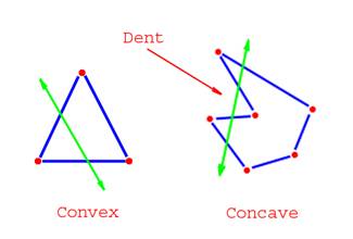

 fluid copper
I tried that lol, like I said, I made it the correct size in blender, ported it to ob, then pasted the memory lod onto it and moved everything around to match it
I have no idea why it breaks
stuck oyster
no idea
sounds like you are doing something funky but cant put my finger on it
very odd workflow
fluid copper
Is it possible that the wheelradius is too large in the config and its causing it to clip into the ground?
stuck oyster
dont understand why you are not doing the memory lod in blender to correct size
no
its not set in config
but in memory lod
fluid copper
I can try it in blender I guess
upbeat wraith
{
    class CA_Magazine;

    class rev_inv_usb: CA_Magazine
    {
        displayName="USB";
        scope=2;
        mass=.5;
        author="Louis";
        picture="\USB\Icons\USB_icon.paa";
        model="\USB\Objects\USBDrive.p3d";
        descriptionShort="A USB";
    };
Does this look okay as a config.cpp file?
I put it under magazines, because honestly, not sure where else to put it for now
Right now im waiting for BI tools to download so i can get BinPBO
upbeat wraith
Its a bohemia interactive tool, the guy in the tutorial i followed used it, figured i would too
and of course i have arma3 tools
stuck oyster
no
then those are what you use
you are shooting blindly now, take a step back
or pboProject from Mikeros if you happened to get those
flailing around with your eyes closed is just waste of time
that config wont be enough as it does not contain cfgPatches class
upbeat wraith
but if im only adding one item?
stuck oyster
all configs are required to be made correctly
1 or 100 items
you cant just invent your own procedure
upbeat wraith
Ah okay, so i need to do cfgPatches, FactionClasses, Sounds, etc?
stuck oyster
cfgPatches only
upbeat wraith
alright
stuck oyster
that is the header of a config
upbeat wraith
would this be enough?
{
    class Rev_vending
    {
        units[]={"USB"};
        weapons[]={};
        requiredVersion= 1.03;
        version= 1.14;
        fileName = "louis_usb.pbo";
        author = "Louis";
    };
};```RequiredAddon will be needed too so your config is loaded after the base configs. "OldmanLoad order" can be used on that. It was discussed not long ago on #arma3_config I think.
fluid copper
When exporting it from blender to object builder it is scaling the memory lod to be much larger than what it should be
I cant send pictures here though so its hard to show you
stuck oyster
you dont have object mode scale applied
for pictures you will need to upload them somewhere and link them here
fluid copper
hmm your right, I applied the scale earlier but it seems to have reset
will give this a shot
hmmm now it wont move in game
odd
it was missing some descriptors in the geometry lod, fixed them, and now its back to bouncing around in game 😦
this is the geometry lod, it has all 4 wheel_1_1_damper's
fluid copper
its identical to the arma 3 samples car
5 components, 4 being the wheels and the 5th being the body, and 4 dampers for each tire
this is the geometry model
stuck oyster
fluid copper
?
stuck oyster
sample car
stuck oyster
each wheel has its own selection
fluid copper
I know
so does mine
the images was just cut off so I said it instead of it being in the picture
stuck oyster
then what you said seemed to mean all 4 wheeles are in selection 1_1_damper
fluid copper
sorry, my bad, they are all named correctly and assigned correctly
stuck oyster
does your memorylod have the wheel physX related points?
fluid copper
stuck oyster
its also possibly you are making too small thing and the physX cant handle it