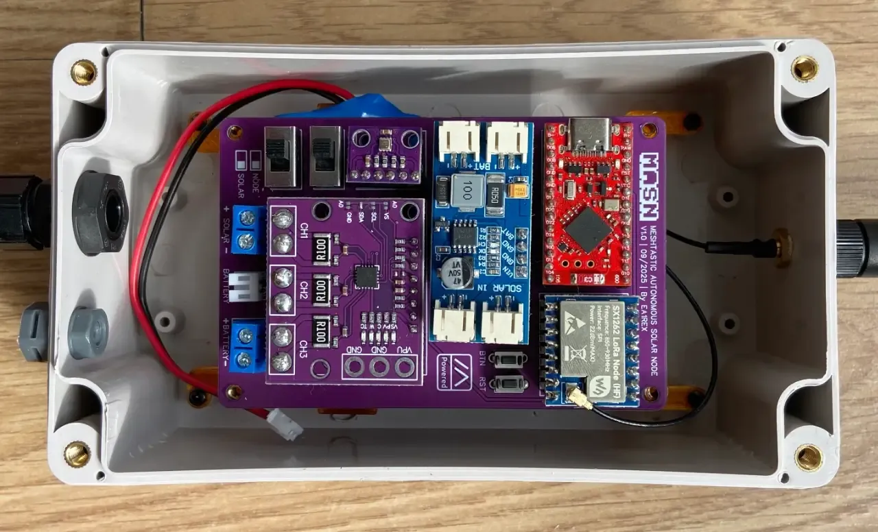
#WashTastic - 1W node based on E22-900M30S and promicro NRF52
1 messages · Page 8 of 1
it is kinda frustrating that it costs so much
i would need to increse my prices to actually keep up with this and make something
Hopefully this batch you won't need to troubleshoot
haha yea
about 451,74€ currently
I sent this
Hi,

I did some price comparing and i found out that at the manufacturer ive used usually 20 boards is about 276€ assembled without the promicro compared to the 452€ i paid on this batch.

The price im paying for pcbs compared to the demand and what i'm gonna get in the end after paying taxes, this means i would most likely need to increse my sale price.
Yikes. Double for the PCB, 50% higher for components...
yeaaa.....
i would basically not make alot from these in the long rung 😅 i need to pay income tax and usd to eur conversio is a thing too
Do either if those prices include any testing after assembly?
Apparently it was free 🤷♀️
But still
Even if it did include testing it's not disclosed
If possible i Will probably just use most of the earnings to order more pcbs without cashing it to my bank account
Tex evasion
the legal kind though! Can't have any gains if you spent all your money on the business 🤷♂️
I did a few cycles of that when I was reselling bitcoin miners during the first boom. Each successive batch was bigger than the last
Yeaaaa
aaaaannndddd all of the washtastics have been sold
congrats! that was fast
thats like about $1400 in few days 😅
👀
time to buy more boards!
you know, you could assemble those in small scale yourself without a ton of investment 👀
cheapo toaster oven, controller, order the boards on panels and get a solder stencil
but i would not be able to ship to usa
hmm
i mean i can
if you know someone in usa, you could ship them like 10 of them
to distribute for you
but its fucking expensive
yeah tell me about it, same from canada
sometimes I can get cheap rates through a company here "netparcel", they're like pirateship but canada
ofc i'm willing to ship if ppl pay lol
If they all sold at the existing price so quick, maybe people wouldn't mind the extra 🤔 dunno
tho idk how to ship outside the EU 😅 what does it require
yeaa 😅
I usually employ the time tested technique of lying on the shipping bill
from $85 to $100
there's like probably 100k parcels entering the US a day
it just flies past a camera on a conveyor belt 99.999% of the time
worst case they just throw it back to you
haha yea
I tried to mail something to florida once and the address reader thing sent it to malaysia 💀
and it was e-cigarette stuff, which is banned there, so it got returned with a big "refused entry" letter taped on .. written in malay
I'm not sure if you can.. I think the price is actually tight from the customer perspective. Doesn't seem cheap to me despite the selling success. But this is just my opinion 🤷♂️
Ill see what i get for a quote with 50 boards
I'd try to get quotes from different manufacturers on Alibaba. For 50/100pcs you might be able to get a better price there than on JLCPCB. For bulk 500pcs, I'm 100% sure you'll get a much better price on Alibaba.
Jlcpcb is the cheapest what ive seen currently
But im selling my boards on Elecrow and they handle all the logistics
And wdym alibaba?
@hot perch
Find quality Manufacturers, Suppliers, Exporters, Importers, Buyers, Wholesalers, Products and Trade Leads from our award-winning International Trade Site. Import & Export on alibaba.com
alibaba means alibaba hahah there are manufacturers also not only things already done....
aaa ok elecrow make it...? I thought when you said you were going to order 50 pieces you were referring to JLCPCB, not elecrow....
Yea elecrow manes and sells


On PCBWay it would be double
Yeah my Next big order will be on jlcpcb
But I am testing nextpcb Right now they asked for a Cooperation
Nextpcb?
yup
Yeah I am switching from PCBWay to Nextpcb Right now
Are they good?
Did you also Talk to jocelyn
yes and no
Ahhh now I get it
This is without a battery 😅

Now it looks bit different

This was with 6V input
5.1V

Max 7V
Min 4.9V i think
Charging the battery

At 370mA

That's a lot of ringing
Just the battery


I could hear the inductor making whining noises i think


Is this the battery charge circuit?
Having a quick look, that ringing can only be suppressed with carefully tuned snubbing circuits which take some efficiency as well.
scope is hooked to promicros bat pins
but yes
its the charging
ill have a video soon ish
It's fine. Battery doesn't care about ringing.
yea but node does?
It's literally a huge capacitor.
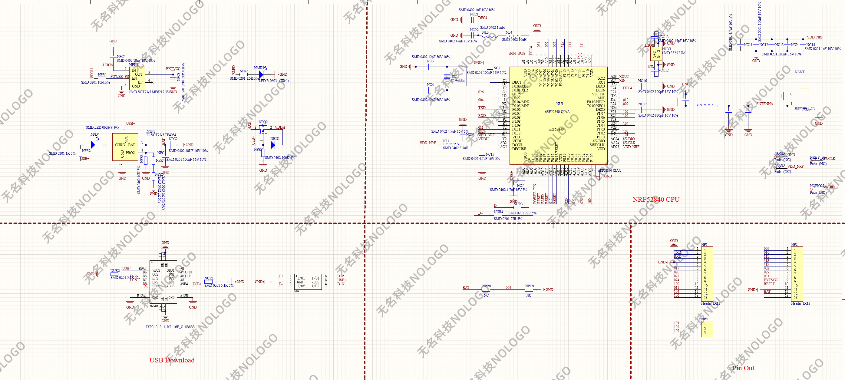
The promicro is fed through the LDO
Is it causing the bootloop?
Filter circuit...

Testing the CN3791 charging circuit.
Battery was at 2.2V
What ldo?
As far as I know, washtastic has battery and mppt in parallel, both behind a BMS that should not 'close the switch' until 2.9~3v are reached. Then, it feeds both promicro and 5v boost in parallel.
Then, the promico nice!nano freeds the bat+ and bat- (almost) directly into the nRF52
low drop out regulator
it basically turns everyhting above 3.3v into heat
which seems to be configured in high voltage mode
yes, in promicro it is
but the promicro is not fed from any ldo, that's whats puzzling me from your statement
promicro board has an ldo (me6217) but is only used for output pin, to control external hardware

the ldo outoput is tagged into extvcc and I couldnt find the extvcc anywhere in the schematic but in the headers section
bat goes into the mosfet (NPQ2) source that switches between usb or bat power sources, then is directly fed into promicro's VDDH
I also tested this soldering a wire to the NPQ2 mosfet drain leg, and the voltage was about the same as in the source leg.
I know what LDO means, is just that I dont understand to what LDO are you refering.
Oh, for some reason I assumed there were two LDOs, one for the processor and one for vext
Yes, if there's no additional LDO for filtering then adding something between the battery itself and the battery pin (which is the only sensible way to power the promicro aside from the usb).
There are some caps on bat pin next to promicro
I'm hopping that the voltage monitor directy tied to nrf52 reset works. If it doesn't then I should tie it to a mosfet that cuts power from battery to promicro
hi iris. my local group is ramping up infostructure deployments but are using sub 1W nodes. I want to pitch the idea of using this board instead to them, what is the state of this project?
They work 😅
i ran v4x through jlcpcb and got a bunch of errors in the part picker. got an idea of what x5 would cost?
What errors did it give?
But v0.4 is 4 layers and cost arm and a leg compared to v0.3.5
If it has some parts not in bom its expected
Since some don't need assembly
I don't recall. I read that the nrf52840 is embedded in .04. I don't have the equipment to do it myself.
There is someone that does in the local group so using 0.3.5 isn't the end of the world if 0.4v is too expensive.
This is v0.3.5

Only thing jlc wont do is the promicro
Biggest difference between .4 and .3.5 is that the nrf52840 is integrated
Also has ina3221
Yup. Im trying to find solar requirements, as well as the battery voltage.
4.5-28v solar input?
Yea but 5V is kinda recommended min 😅
I see now the image eplains both
Haha
Yup
I recommend using the WashTastic variant since its aware of the 1W module
Why isnt the 0.4v aware of it, jc.
It is 😅 I'm talking about the firmware
Aight. I will try putting 0.3.5 through JLCPCB tmrw. its late.
Just remember the licence :)
this is the doomed board from elecrow, right? why do you keep it attached to the second promicro ?
I mean, once diagnosed the bootloader, technically you could just unsolder the parallel promicro board and put the promicro in the v0.3.5 to work by flashing the bootloader, couldn't you?
Been too lazy to remove 🤣🤣
Here we go

U can exclude the shipping
So its $740,59
About 636.53€
I'm making no profit yet 🤣
Rather I'm negative lol
Hehe told them that they have very expensive compared to other places 😅
Ofc didn't tell it was jlcpcb
If i did math for 50 boards i would get 2.5k€, elecrow fee and taxes taken out of it.
Now the jlc quote isn't that far off 😅
Not too familiar with JLCPCB yet, what is this quote for? I see its for 1W 0.3.5. Is that $740.59 for 50 assembled 1W nodes?
That is cheaper per unit that I expected. Of course it needs the pico nr52 as well but still not bad.
That's included 🙃 atleast it was on the last order hehe
Oh does eleceow have the pico then?
Elecrow is not like jlcpcb that has warehouse with parts, most of them are bought to order basically
But Elecrow does sell promicros
Very nice. Makes it easier without finding someone willing to attach a separately bought board.
I would do it anyway before selling 😅
Are you saying that it comes with the order but isn't attached? Again these weren't as far as I'm concerned going to be sold but used as infrastructure nodes. Gotta test them first of course.
Elecrow solders, flashes and tests these boards before they even leave to a customer 😅
Basically what i did before i partnered with Elecrow
Washtastic is my first board with MPPT built in and my math says I need at least a 14W panel for a Washtastic to survive our winter
I don't have a go-to solar panel that can benefit from MPPT in the 15-20W range. Any suggestions?
All the ones I've bought so far are for 5V or 12V. I could buy a 12V one and just not use the charger, I suppose
wait rly?
hmmmm
That's assuming 3.3Wh consumed per day
wdym not use the charger?
I've been getting 20W panels that come with a PWM-based charger that handles 12V batteries
I used Goal Seek in Excel and asked it to set the Solar power balance (Wh) cell to 0 by modifying the panel wattage in the upper left

If the weather de-rating of 90% seems absurd, it's because we can have multiple weeks of heavy cloud cover in winter
consumption ofc also depends on ur tx power and how frequently u transmit stuff and how active is ur mesh
mm
Do you know average power draw for a Washtastic? I worked up the numbers for an Ikoka and am assuming Washtastic will be pretty similar. Something like this

That assumes 120mW during RX and 2.55W consumed on TX
https://github.com/valzzu/meshtastic-pcbs/tree/main/WashTastic#power-consumption
was measured on older version of the board

GitHub
PCBs i've made for meshtastic. Contribute to valzzu/meshtastic-pcbs development by creating an account on GitHub.
Putting the files through elecrow throws a non-specific error.
Is a testing guide required?
No
What error?
Worked fine for me
Jlc is the cheapest for small quantities


Not sure what I did wrong there. I proved the files, changed nothing other than quantity and then requested the quote. Error.
Not with these files.
Elecrow has started a new batch of WashTastics
Am I doing this right? When connecting a 12v lifepo4 battery, the red light next to the battery connector illuminates but the pro micro does not.
If I connect USB-C to the pro micro only, I can configure it... Sort of. But not the radio.

Red light is reverse polarity warning
Sorta answered my own question when I zoomed in on my picture and saw the LED was labeled "WARN"
My fault for trusting this cheap barrel jack... the wiring colors are reversed 😩
oh and btw, that battery connector is only rly meant for 3.7V cells :)
ok, gotcha. What are the power settings for? If you did have 24V, where do you apply that to the board?
yea i do kinda need to make it better 😅
Ok.. still having a problem. If I hook up 3.7v (a single 18650) with the proper polarity, no lights come on and the regulator next to the promicro starts to get hot VERY quickly
wait, dont tell me its the 5V boost

the grey inductor or the black ic?
sorry, L1
I think I smoked at least one when I fixed the polarity 🙁
(the promicro at least)
ok! 2nd one is fine.
L1 is the small inductor 🤔
i'll replace the promicro and go from there
nothing in that circle should get hot 😅
only thing tha should get warm is the charging ic when charging
Call me a chef, i'm cooking these things
elecrow is making more of these :)
this time 50 boards 😅
hopefully they dont sell out in about 2 days
as long as you don't have other random people buying up 5 at a time 😏... but hey there are worse problems to have than "these things are selling too fast"
like taxes 😅
i have uploaded IBom for those that like those lol
https://github.com/valzzu/meshtastic-pcbs/blob/main/WashTastic/V0.3.5/InteractiveBOM_PCB_1W-meshtastic-node_V0.3.5.5.html
GitHub
PCBs i've made for meshtastic. Contribute to valzzu/meshtastic-pcbs development by creating an account on GitHub.
how much battery/solar do you typically like to use with these? I was planning on doing 5w and ~5ah

It tucks very nicely into a standard US waterproof junction box with three 18650s. Going up today!
Giving JLCPCB a go with the gerber/BOM/picknplace.
I am looking at the InteractiveBOM and see differences that I am trying to work out before placing an order. R13, R26, C13, maybe more, are not populated in the InteractiveBOM but are populated in the BOM.
Should I alter the order so that it matches the interactiveBOM or are the 0.3.5.5 files good to go as is? Every part in Bill of Materials gets selected and assembled?

GitHub
PCBs i've made for meshtastic. Contribute to valzzu/meshtastic-pcbs development by creating an account on GitHub.
If u want the newest board then i want the 3.5.5 files
Should be fine
Headers aren't placed for a reason
Okay. Another thing I seen while viewing the InteractiveBOM was these holes appear offset and lining each hole up in the center still shows the offset.

Hmmm. Needs a little bit of scaling...
@olive basin I made a twice pannel model and fixed the zipties holes

not sure if the model of panel you got there fits here.. I made it for my original solar panel, to fit two in parallel
145x145mm
165.5x131.5mm 😅
Got 5x nodes in production. 🤞
Now for soldering


Is there a significant difference between 0.3.5.4 and 0.3.5.5? I unfortunately had a batch made of 0.3.5.4 like two weeks before the 0.3.5.5 files were available.
What would I search for if I wanted to buy pin sockets for a press fit pico nrf52?
anyone have some to sell. I tried to use the 3.5.5 files in JLC and it didnt see m to be happy, a lot of components had issues

that is normal
Thats fine
I was just trying out the tester firmware uhh, is it normal for P1.00 to just stay high the whole time? All the other pins toggle as expected. 4 boards the same, different sellers
5/5, maybe because I'm checking it with a multimeter? No load?
lemme check
const int pins[] = {
0, 1, 2, 3, 4, 5, 6, 7,
8, 9, 10, 11, 12, 13, 14, 15,
16, 17, 18, 19, 20, 21, 22, 23,
24, 25, 26, 27, 28, 29, 30, 31,
32, 33, 34, 35, 36, 37, 38, 39,
40, 41, 42, 43, 44, 45, 46, 47
};
those are all the pins
so yes it should not stay on
🤔 yeah the code looked right to me too, hmm
I'll try to get a led wired up
all I've got are some smd rgb ones from fixing my keyboard lol
It indeed do be blinking, but it's going really dim instead of off 🤔
Yeah and there's a bunch like it from different batches so, it's probably fine
yea
ah that's the user button pin on the faketec pcb anyway, as long as it works as an input idc
ah lol
Anyone willing to sell me a couple of these pre-fabbed so I can design a case for em?
@meager spruce you got some in the stable?
You're in the same neighbourhood, I think.
I think i have one too
I think I have one not in use, but I don't recall if @tidal dawn has any or not, he's closer. Otherwise I can spend some time to build one but it's an older revision I think 0.3.2, gotta check
No Washtastics here
If one wants to make a case id recommend doing it on the newer bigger pcb
Yeah just the newest one would be great, @olive basin I'll DM u 🙂
Spoke to Iris and the EU to US shipping is crazzyyy, LMK if anyone's got some in the US 🙂
Not to mention shipping in eu vs domestic
I can send a parcel here for like 7€ for the smallest and its like 23€ elsewhere lol
Xxs here and s elsewhere
So yeaaaa
Maybe I'll just get 20 to have them in addition to the next JLC order
Q? What's the normal way to wire up the washtastic
Can u send a pic
Not home atm so can't check
theres a reason why i dont ship to outside of the EU 😅
anyway first time doing that
welll
i did send something to uk but dont count it
I have a few 0.3.5.4 boards that I just had made a month ago. Don't know if the layout or size changed to the 0.3.5.5 revision. I am in the US.
the important stuff are in the same places
I was asking because my rak says 💯 battery and I'm wondering if there is anyway to know the charge
should not

adc value is most likely wrong
hey this hasn't been published outside of this meesage, right ?
you should publish it in your printables account :p
Got any pictures of an assembled one? Feels weird posting a model without photos, makes people think it's untested
I don't have any of the tester boards
sure
thing is, someone ask me for the tester and just found that I built mine and iris published everything on her side, there was no manual or files all together available to build it


Oh my bad I forgot to check the thread again, I'll get on that now

Time to add da link to repo
cool thanks to all!
Not like there will be alot that will use it but its there if someone rly wants 😅
yeah, there's not much people assembling more than 5 nodes
but those who do, really appreciate it
Oh yea probably
On the gerber files when I upload them it says J2,J3,J5,J5,U2 do not exist on the BOM, can I just ignore them?
yeah, you can. Look at the board. Those are different type of connectors
Ok thanks
Minor update here, the boards don't like 12v. Fried everything on two of them, MCU and radio. Expensive smoke!
Huh, it's meant to handle 20v too 😅
Is there visible damage somewhere?
where did you plug 12v, in the solar charger port or in the battery port?
oh yea that too
Battery.
@olive basin I'm beginning to think you need e-fuses, or at least Zeners and polyfuses.
yea battery is max 4.2V
maybe
did not think someone would actually do this
They're not idiot-proof, but they add a level of idiot resistance that might prevent some of these issues.
Trouble is that batteries need to be bidirectional
yeaa
But can still use zener and polyfuse to protect against over-voltage and reverse polarity.
Or just bite the bullet and find an efuse.
There were some on the list I sent you
Trouble is, it's either another dollar in BOM cost, or an extra 10x10mm of board space.
the list with the chargers?
The instructions as they were written did not make it clear. I thought it was setting the voltage for the device as a whole, not just solar.
It's my mistake and I'm not asking for anything from it, just a suggestion to put that in big bold letters.
yes i know i need to make it better. but also theres these red voltages where the connector would be
https://zipline.valzzu.xyz/u/6bGQGF.png

@heady mulch i may be blind but dont see lol
Oops, wrong place
That is helpful. I ordered from Elecrow, and those images flash by pretty quickly so I missed that. This description on the page is what also confused me. The text says nothing at all about battery voltages. but I understand it now.
For efficient power management, the board integrates a CN3791-based charger, allowing battery charging through a solar panel or any 5-28V power source.
I would also put some verbiage in the description that the battery connector is "only suitable for 1s (3.7v) lithium ion batteries"
Take it or leave it on that feedback. Not everyone that orders these things is going to be at the same level with this stuff. I'm happy to own up to my mistake here but others maybe not so much. A little extra guidance (and clear warnings) could save you some grief in the future.
RIP
This person is way better at documentation than me, I like the way they have stuff laid out. The other thing that I found interesting was the support for multiple battery chemistries... being able to do lifepo4 or LTO would be amazing https://lectronz.com/products/solar-mppt-charger-for-meshtastic

Solar Mesh Baseboard with RAK4630 (868 and 915 MHz) and MPPT charger.
i do have plans to eventually support multiple chemistries
LiFePO4 would be really nice for a ton of reasons... low temp performance and cost particularly. And there are some great options for high-capacity cells. I have a bunch of 15ah cells that I bought for like $3usd/ea
We might have soon another batch of WashTastics on sale at elecrow
Money money moneeee
80$x50 is alot 😅
Minus 5% comission fee what ever
Minus tax
Still alot
Damn
The Washtastic firmware on mrekin's flasher is only for the newer versions with the NRF52 IC, right? I'm assuming older 0.3s with Pro Micros should still use the generic DIY TCXO builds but wanted to double check.
nope :) its for all of them
only change is that the firmware is aware of the 1W lora module
Ohh great! Thanks @olive basin 🙏
I couldn't find the variant.h on GitHub (but I'm very dumb lol). Any chance someone could point me in the right direction?
Ahh thanks so much! Think it'll work for other standard pro micro builds with a 1W radio (e.g. Tom's Liberty MeshMess with an e22-900M30S)?
Yes, should be fine.
Main thing is that Iris took the initiative and made her own variant.
heh
PLEASE READ!!!
https://github.com/valzzu/meshtastic-pcbs/blob/main/WashTastic/Readme.md#note-for-ppl-who-have-ordered-this-before-i-was-notified
GitHub
PCBs i've made for meshtastic. Contribute to valzzu/meshtastic-pcbs development by creating an account on GitHub.
do we know what that even causes ?
More susceptible to transient voltage wibbles
It's a RC filter
It's only 100nF - can chip one off anything
ah so maybe thats what is causing the ripple i saw originally when a battery isn't connected with solar only but this is on bat + not sure if that would impact that i'd have to look at the solar path

Yep
the cn3491 ?
that was solar input of 5v without battery
yup
even with added cap it was still pretty bad
but the battery sinks it all
just wonder when the xb chip is in low-voltage protection what how that would look
maybe should use the scope to see whats really happening
this was with 330uf

but that was just at the pro micro bat+ and gnd
where it was added
The NRF is fed through a ldo anyway - they're very good at filtering out that kind of noise.
it didn't boot unless there was 100uf there
Or a battery?
right or battery
i have added some caps on the bat line next to promicro on later versions
with battery that is essentially all clean
I was discussing this on the dev call last night, btw. The net consensus is that even with cutoffs, even with watchdogs, even with the improved write control in littleFS, the NRF52 is still prone to getting stuck in a loop. The answer is simply either: don't let it run flat, or be prepared to press the reset button.
That goes for RAK, seeeeeeeeeeed, whoever.
yeah
i'm getting ready to just put a lot more battery in these nodes
would be nice to have the reset hold on these though
that you proposed built in
Btw, that hysteresis circuit can be fit on a cheap board about 5 times, and JLC will bang them out in 5s. How many people do you know with solar nodes that would want one?
if you think about selling them as stand alone i can imagine that people would buy them for raks and other nrf that have this issue
the major issue for me is the US current tariff and trade bs making ordering anything a nightmare
That's why I was thinking of a through -hole one that could be made on perf board.
yeah
But it's so much easier to find SMD stuff these days.
also add this into the schematic as standard so it doesn't have to be added
I still haven't got the hang of them yet.
neither have i
I wasted this morning adding it to one of my designs, and then remembered that it also works with sodium ion 🙃
i guess could just make a project that has alot of these things
i found a cool pcb design for using bunch of just dev through hole components so just a pcb could be used and build out of easy to source parts https://danielpcostas.dev/masn-a-simple-and-open-source-solar-node-for-meshtastic/
Learn step by step how to build a solar Meshtastic node with the MASN PCB: firmware, assembly, basic setup, outdoor enclosure, and usage tips for a reliable autonomous deployment.
I was going t split up the sampler board into bits, but haven't got the hang of it yet, either.
Yeah, my first introduction to EasyEDA was making a layout for what was on my protoboards
I was kind of put off by needing to get 5 boards 😬
Doesn't seem to bother me now...
lol
That’s sick
Me to 😂
its easy enough to have pcb's made in the US but PCBA service is not so easy
so a board like above makes it possible to assemble a working node out of easily accessible parts
thats generally what i meant by that
it's like a more featured Xiao BLE just with 22dB instead of 30dB radio

yeee
Not sure if you can help - am trying out an order of the 0.4 Washtastic version on jplpcb. It tells me "the below parts won't be assembled due to data missing. U8,U11,J1,U12,J3,J4,J5,J6 designators don't exist in the BOM file." Am trying it with the BOM no connectors 0.4 and the PickAndPlace CSV for 0.4.
Yea thats normal but wait for me to update it since theres a slight issue with the battery protection
Atm at work so can't
No worries, thanks
Heh

should add in the reset circuit being suggested by Nom https://discordapp.com/channels/867578229534359593/1194757507013427250/1442718736342585456
This is Gore
nah
This looks like a lot of heat was applied, I’m havibg doubts about the integrity of the BMS chip.
Can you Test if it works with 15kV and 2kA
I Need those datas
im not gonna be that one guy who showed 12v

v0.3.5 and v0.4 has been fixed hopefully
meaning new gerber has updated track for this capacitor and nothing else?


A few test boards...
For a hyper-aggressive cutoff (3v falling, 3.4v rising)
you're in the UK right ?
did you buy up all their stock of those? lol or did you have to preorder them as well ?

Populated pads with the target resistor values prefitted, and spare pads for when they're inevitably wrong
Battery at the top, enable at the bottom, and the resistor points broken out for good measure.
thats nice you could just put common values you think are right with solder bridges or something to easily change it but i assume once you know the right value it shouldn't need those ?
or maybe thats what those r1 r2 and r2 pads are
They're for adding extra resistors
The small ones are 0402, the others are 0603 which is the limit of my skill level.
The 0402 are easy to depopulate ✂️
i've soldered 0402 once and don't wish to ever do that again
do you think the schematic you sent is probably correct ? i know you make no guarantee without testing it
Iris did me a favor and added it and i was planning to order some board with this circuit in place i'm sure i could just cut traces if something isn't right but modifying it with its location and small 0402 compoents would be difficult
I love my 0402
I think try that chip out on some Veroboard, and use chonky resistors to set it.
Yeah, now you do!
Cos you got an army of robots to make stuff for you!
Whaaaat
Naaaah
Totally not
Also i think elecrow is moving the resistor
No
Cap i mean
I do also kinda want to find something to replace the cn chip
Its okay but could be better
That would totally not make me redo v0.4 layout 🙃
That i totally have not thought of doing for ages
And totally have not neglected
And totally have not forgotten about it untill few days ago
I tacked the cutoff test circuit onto the bodge boards. They'll be here in a couple of weeks.
And I ordered 5x new charger boards, cos I'm 100% certain of this design.
Are u sure sure
@heady mulch if you come up with a good design and are either selling them or let others order them let me know because i'd like to add some to the boards i have already
it looks like people have good luck selling good whole built nodes for quite a large margin
like this
Eventually yes
When i figure out solar in Finland
I guess that's using 25w panel
That's in the range I'm thinking
But they are expensive as hell
there are cheap panels meant for charging car batteries

ECO-WORTHY 25W 12V Solar Panel Kit Battery Trickle Charger Maintainer Waterproof Solar Panel + Adjustable Mount Bracket + Upgrade Charge Controller for 12V Batteries Cars RV Boat Motorcycle Marine

yeah but maybe you can find those types of panels cheaper than just the panel
for some reason if you look for car battery maintainers versus just the panel
its much cheaper
see
Its still expensive
Would be cheaper maybe if it didn't come with the charger
Ye

I see apparently free shipping too
I got lost here. What did you fix?
The battery protection had s capacitor in a wrong place
Apparently prevented booting if battery drained
Can't confirm nor deny
i solder 0402 😄

it can be done it isn't easy and its a pita and its especially difficult if its in a place that isn't easy to reach with an iron next to tall caps or other stuff
its not that hard 😉 i did that few times already

i had to fix a RC remote by replacing a 0402 resistor with a different value
i got it done
just a pain
you soldered all of those by hand ?
nah - no pain no gain

Yes Sir
Would you mind providing the p/n that gives this .4v hysterisis? Thanks.
For sure, but it's not just one part 🙂
Wait til I've solved it first!
I only ordered it a few hours ago!
Just curious about the IC used.....
You could use a tlv840 tied to a fet
The tlv840 lets you program the hysteresis with a cap
That's time delay, not rising Vs falling threshold
Adding hysteresis on a single input chip is really hard.
There's some nanopower ones that would be great, except they're only 4 pins.
I was planning on using the TPS3806J20DBVR. It wouldn't be this one, would it?
No its not, but that's a good find!
Sorry, I fell asleep before i had chance to answer
I'll look it up later
TPS3808G01DRVR
I looked at it's datasheet and the big thing I see is that it's Vhys is only 1-1.5%, which for a Vit (threshold voltage) of either 2.79V or 3.07V; I feel that that hysteresis is too small (~0.03V). Depending on battery chemistry, I believe the hystersis should be about 0.2-0.3V. The TPS3806J20DBVR hysteresis is fully programmable.
Thank you for letting me know what you found. It is always great to see what others have found and are using!
That's what the extra bits are for 😉
Basically, need a chip with independent sense pin, and then feed the output back in, so it changes the trigger level.
The TPS3806J20DBVR has independent Sense and Hysteresis pins; so 4 resistors and the IC and you are done.
So my design is definitely wrong
I forgot this one is open drain, not push-pull
Oh well
What's one more round of rework? 😬
Heh
Oh deary dear 😭
I think I set it up to work with either the 2.9v cutoff or the push-pull version, but then never swapped out the core chip
Oooooffff
So at the moment, if it switches off, it will stay off...
But luckily it will never switch off...
Ack
Whatever
I only got 5
Ahhahahaha

Mmm
so the only problem with the cap is it won't boot up if battery gets from too low, to "enough" and the reset/power button need to be hit? or does it affect the solar charging in general?
ok
but its now like datasheet shows it
@untold wharf did you already start designing a case? im stuck at the switch for on/off its so smoll
I have not no, I am waiting on some china parts
i prob should maybe change it since one person broke the switch lol
On/off will be done via battery cutoff on the BMS AIO that I am using
Not gonna expose the on/off from the board
Ya there is some good panel mount options or toggle push options
Toggle push on/off buttons are the best foradapting to cases IMO
maybe could use something like that
the black slide part is like 1.3mm square, dont know how i would be able to print something so smoll
ahhh okay, i want to create a case for mobile use
yeah me too
P1.01/02/07 are not connected right? do you even solder them to the board?

How are you adding the switch? Solder or just battery line cutoff?
i'm not here often, but i noticed tom really likes his free real estate 🤣
So I can fill it with capacitors


hat it when the GND steals all the heat from my soldering iron
hotplate
👀 to fit a 5000mAh lipo liter battery in the bottom or 2-3 Li-ion cells. buttons are useable and the slider for on off too. lets see of it works
edit: buttons work excellent, usb slot needs rework to fully insert usb cable

yep, the logo is upside down 🙃


looks good either way
only problem left. when screwing down the board, it lifts up on the other side where the usb is.... need to hold it down somehow
not as handy, but it should fit 3 li-ion and 5000mAh lipo batteries
How much are the newest version of the washtastic board? Anyone tried to order them in the U.S.
is it possible to change the device lora settings with a physical switch? like using the washtastic in the city daily with lower dbm and when in the Mountains flip a switch and get full power
maybe if u modify the firmware
then i would need to modify every new release right 😮💨
basically
You can add attenuator. Remove it for mountains and add for city usage
85 is kinda expensive 🙁 if i couldnt do it myself i would not pay that
I have to cover the cost of manufacturing and make something out of myself
So can't help it
I understand, i wont ruin your business. Just saying …
i know its not the cheapest
its more about saving battery life
Well this node dont use as much as heltec so you save anyway. And attaching attenuator is the fastest way imo

Not cheapest but not most expensive but clearly its awesome. Already soldered like 4 of them. 😉
Heh tx takes like 700mA
At 1w
True but its not transmiting 100% time right ? Where heltec uses that all the time, for wifi, leds, screen other mambo jambo
ok, since the node does a reboot after lora changes, it isnt that intersting anymore
Ahhh thats pricey
Curios if this board has networking?
It's nrf52 so no
Cuz me selling it heh
Doh’
maybe something for thr doc.
you can enable 500mA charging on the bottom side of the nice nano 🙃

well, still better than 100mA
True but ive seen reports that it doesn't charge anyway 😅
Guess what, the fucking boards don't work again!!!!
I did send them the promicro ota bootloader iirc
Id did send the adafruit one know so we'll see
Like how hard can it be to just work aaaaaaaa
Thats why i dont solder it directly to pcb 😄


Indeed
Or somehow i sent the wrong bootloader
@olive basin Do you have any assembled boards available?
Thanks!
Thanks for checking, yeah how long do you think soonish would be?
maybe a week i hope
kk sounds good
anyone has any case for the WashTastic pcb please ? 🙂
@crisp tundra in the afternoon i can provide the stl files if you want
perfect 🙂
u need it with space for batteries?
depends how will it look. but it is battery / solar powered. now glued to 3x18650 holder
3x18650 holder should fit in the 20mm case
looks exactly like tho one above
u need extra holes?
like the gray one with pink buttons ?
ok, this is the only available 3d printed case at the moment - right ? 🙂
didn't find any, thats why i made this brick
I'm designing a mounting plate for use in off the shelf enclosures, those with a 5mmx5mm grid plate, and the Carlon waterproof 4x4x2in box.

WashTastic PCB EnclosureThe enclosure is designed specifically for the WashTastic PCB and includes a modular battery compartment.Battery compartment options:10 mm version: Compact space for a 5000mAh LiPo battery.20 mm version: Larger compartment capable of housing three standard 18650 lithium‑ion cells (3 × 18650).Assembly hardware:M...
There are others but that one is for a older version heh and probably not released
you building such a device?
Would be funny yes
Hi, i have solered one extra for one dude from my country, now he says its not needed anymore. im willing to sale it for 70Euros if anyone interested. I can send photos or measurements - just PMme
i have approved of this sale :)
Here is a simple mounting plate I designed for version 3.5 of the board, for the common 5x5mm grird mounting plates found in many encloures: https://www.printables.com/model/1525057-simple-mounting-plate-for-the-washtastic-board-v35

awesome
@olive basin Are these being sold on the US market yet?
Would I be allowed to sell prebuilt solar nodes with these in them on the US market?
Technically my license only applies to the board itself.
Haven't thought of this tbh 😅
But u aren't selling the board on its own but a complete node so i guess u can.
If u decide to order from jlc consider sponsoring me on GitHub for any amount u like, i would appreciate it :)
Does the license apply to kits aswell?
U would be selling it with something, not alone so I'll say no but I would still appreciate if u considered sponsoring :) don't need to be much
currently charging with 400mA via the usb-c port 😎
if it works it works lol
hehe :) elecrow has finished assembling
and they moved the cap

so go nuts with these boards lol
next version when ever that is relesed will have an efuse to protect the node from higher than 1s lipo voltages just in case
also would swap that lora to to e22p but that would mean id need to do 2 orders on elecrow and have 2 differrent products maybe
ill have to ask
so if i put 12kV on it its gonna survive?
just in case
no
if i want to desolder the tiny cap, how big of a chance is it, that it just burns on my iron tip 🤣
yeah, dont even have such a smal tweezer to hold it
i should get some small angled tweezers
yo, how do you remove the pro micro from the board without destroying? really want to set the bridge for the 3-400mA charging
which side is easier? bottom of the pcb or at the pro micro
just have to be carefull not to heat the board too much too close
bottowm
yeah no hot air gun here 🙁
i placed it on the Kitchen stove, it was getting hot, but the hell. i could not pull the pro micro off, to scared to lose some other components
it takes a bit time
yea thats solder
fkux
also the whole board basically is a big ground plane so it does take a while
scared to fry it ^^
😅
i just did some math and i realised i could lower the price of washtastic if i keep ordering like these in batches of 50
its fucking $16 per board about
could make it more affordable 🤔

@heady mulch
oh yea i can remove the mosfet since the lm73100 has a reverse polarity protection
ill keep the light tho
Does the lm73100 have rpp? What's the reverse voltage limit,
you can add headers to the board so promicros are removable - like i solder them at home ^

i can only find max of -12
nothing more


now my board supports e22p
@crisp tundra
would have wanted it on the top side but no space
i mean there are space but not close enough

also finally added text on these pins xd
that resistor will not be there
u have to short it manually, will make elecrow do that
np
I noticed that It was about 20 dollars per board when I was looking at buying some
But that was also before the terriffs happened
It rly depends on the quantity
also I think the part quantities are messed up somehow


lol
It's funny looking at elecrow statistics where ppl bought these from
Like 99% is usa 😅
Yeah, tariffs have done nothing to shift the base
Also i have one person in my emails who asked if i have some and what it would cost
For their meshcore network
Well see how many I'll be making and sending to usa lol
Eh, it's fine. It can be used for whatever, really.
Unless they're asking for design or branding changes...
I did have one person (who clearly didn't know me) ask if I could remove the  logo...
Not yet atleast 😅
But will not change xd
Told them that i need a number how many they need/want to give a price 😅
lawl
I checked GitHub and the bom file does look fine to me so idk
Must be jlc
only one oopsie 😬

nooooo the tinies of the tiniest restistors next to R7 is also swoped away
thats only adc 😅
found it in one of the holes for pro micro 🤣
hmmm if U4 (5V boost chip) is misplaced a little bit, does it affect the config saving of the node ? node is running but when i'm about to save, it doesnt save anything, even when it is also connected to the pc
edit: if no battery is connected, shouldn't the config saving still work? (yes should still work, tested with another node)
seems like the pro micro is fried?
but i was able to flash the promicro new, im confused
all i know know u cant tx heh
can't set region, after reboot the settings aren't saved
cant do anything as the region must be set, but after reboot nothing is saved
yea but does it save with a battery?
no
yep
what do u see in the cli? like does it see the lora
but reflash worked
Connected to radio
Set lora.region to EU_868
Writing modified preferences to device
Writing lora configuration to device
WARNING file:stream_interface.py __reader line:216 Meshtastic serial port disconnected, disconnecting... ClearCommError failed (OSError(22, 'The I/O operation has been aborted because of either a thread exit or an application request.', None, 995))
flashing between firmware versions work, but set configurations doesnt. idk 🤣
Older or newer firmware?
first from 2.7.15 to 2.7.17 and back to .15 again
even if i did damage the washtastic pcb it shouldn't affect the pro micro in this way or am i wrong?
it worked beforehand
heated the whole pcb to desolder the promicro again and resolderd the promicro again

So you can solder pins to the pcb and low profile headers like “pins up” to promicro

Yeah, I've got some 7.5mm pins and 2.5mm sockets for that purpose
didn't knew those exist, good to know
so i guess it is desolder again and test a new one 🤷♂️
You can try like this guy made this screen

I test my promicros by attaching them to a breadboard with lora wired and testing if it works, if all good then its ready to go, if something is wrong then well …

yeah well, it worked beforehand ^^
got one node with headers to test every promicro, but yeah, this one died afterwards seems like

Thats why few milimeters for detachable is a winner
would have worked fine, i just wanted the 500mA charging option and had to desolder it again, maybe that cooked it
How solid is this ?
Surprisingly solid
Very stiff to get apart.
I recommend using a spudger
Ill try this in future.
Hmmm.....
yep the promicro is fried
Sleep well, lil buddy.
Earlier boards had a hole for access to those jumper pads on the ProMicro.
i heard the T55 hotplate is popular, any other recommendations?
In this price you can get something bit bigger. I have similar to t55 and its small. And if i were you i would look for hot plate with this arm that push pcb against the plate so it heats better and wont move when you want to move the parts around
Like mechanik ix5 ultra
washtastic pcb also something wrong 🙁 new promicro restarts when try to tx. i guess the 5V boost chip is misplaced, maybe shorted
always the same output.
WARNING file:stream_interface.py __reader line:216 Meshtastic serial port disconnected, disconnecting... ClearCommError failed (PermissionError(13, 'The device does not recognize the command.', None, 22))
next promicro gone 🫡
I have that
For tx u need a battery
Promicro can't supply enough what the lora requires
with or without battery, same issue again. promicro reboots when try to tx or saving a config
standalone it worked , after soldering it to the pcb, this error
Hmm
i guess U4 is misplaced and causes a short. my fault
this footprint.... arrghhhhhhhh

hahahah not your fault, i moved it when removing the promicro 🙃
But yea it's not the best
2.5V short peak when reboot at 2.9V
Oop
on the 2 holes next to the qwicc connectors
guess i will need a hotplate and some suction tool to hold this tiny chip. inventar is growing 🤣
ahhh i think i saw a video from you about this
Found one!

Isnt this one with the integrated inductor?
Yes.
But you have to be careful what you say around it, because it doubles as a summoning circle for creatures from the inductor dimension.
If it begins to glow, make the sign of +++ and begin the exorcism process from step 12.
🤣🤣🤣🤣
@olive basin did you thought about a mosfet between VCC from pro micro and 5V boost IC switched by the battery? this would allow the usage of USB without battery. the 3.3V regulator on the pro micro should deliver 800mA. i think that should be enough
The LDO datasheet says 600mA
and I'm fairly sure the E22-30db uses ~1A @5v during TX
hmmmm okay
Yea it's close to 1A
also, usb without negotiation should not deliver more than 500mA
someone emailed elecrow with this
I just purchased a Washtastic V0.3.5.5 1W node, and I am unable to flash it. I followed the instructions to load Meshtastic v2.7.15 (for nRF52840) and it seemed to flash. I used my iPhone app via BLE to configure, but, after entering PIN 123456, the screen only said "Communicating...." and never fully connected, e.g., green "Subscribed" message. I then tried to configure with CLI, but, when I first went to set up LoRa region, frequency, etc, it froze after printing this: meshtastic --port COM4 --set lora.region US --set lora.modem_preset LONG_FAST Connected to radio Set lora.region to US Set lora.modem_preset to LONG_FAST Writing modified preferences to device Writing lora configuration to device I thought I should erase and re-flash, so I then flashed using Factory erase 6.1.0 .uf2 file as that was the correct one given what was indicated in the text file. Since then, I have been unable to get the device in DFU mode. The blue LED is blinking rapidly and the red light is solid. Please help and thank you.
my biggest suspect is no battery lol
so it wasnt me as i solder them myself 🙂 And im not in US
first i would confirm the bootloader version and re-flash it. as far as i noticed you can operate it without the battery it will just errors that unable to tx or something like it. i was able to connect, change things and then connect battery and use it. Then if that wont help i would go for next promicro 😉 but thats me.
Elecrow did test all of them but with cli so can't say anything about ble aspect
I have seen it not save any settings without a battery
'Factory erase 6.1.0 .uf2 file as that was the correct one given what was indicated in the text file' ?
what file?
There's a text file in the dfu drive
When you double reset, it's not an empty drive
I know that file.. but... that version doesn't sound familiar, so I though the comment refered to another file.. somewhere else
the one I'm using is 0.9.2 and that's way modern
so.. no sure what it means 6.1.0
knowing this, looks like commenter flashed wrong file and burnt out the bootloader
maybe he meant 0.6.1 which was the one usually recommened by the meshtastic docs files
mmmm .. maybe he's refering to this:
https://github.com/meshtastic/firmware/raw/master/bin/generic/Meshtastic_6.1.0_bootloader-0.9.2_s140_6.1.1.zip
He's referring to the soft device
I don't understand this.. what's the soft device ?
The Bluetooth implementation in the bootloader
There's two variants: 6.1.1 and 7.3.0
6.1.1 is older, but the bootloader is smaller as a result
Xiao etc. use 7.30
Promicro is 6.1.1
It's a sub-version of the bootloader
Perhap
Or perhaps they did that stupid thing of incrementally updating the bootloader...
thanks
Yeah, it's 100% confusing
now they have no interface 😅
Oh

Meshtastic —noproto is your friend
The commenter already said that tried to configure node using cli, so he is already familiarized
Oh yea duh
Pastebin
Pastebin.com is the number one paste tool since 2002. Pastebin is a website where you can store text online for a set period of time.
Sx1262 init failed 😅
Darnit elecrow

But you are limiting your sales of replacement boards😆
Preferably i don't want angry support requests cuz they plugged the battery in reverse and fried it
This is the customer?
Yes
Ok, ok, I'm convinced. I'll add them to my designs, too.
Apparently works now :)
I stayed up til 3am adding LEDs to my design...
guess who ordered those and whose pins are to short
its alive again!
@heady mulch
charger is on the battery side before the cutout


Yes, the lm73100 is a diode - no backsies
Pgth only controls pg
ah, idk why i have added it 😅
Because the data sheet ain't clear
makes sense then xd
ill remove it then