#WashTastic - 1W node based on E22-900M30S and promicro NRF52
1 messages · Page 3 of 1
SWEET!
WAIT, So i could put a 12V panel right into it???
Why you put all the cool things after I buy my node
Yes! I think I asked for this, epic that you made it 😄
I'd been asking for it for awhile.. LOL
Yup
U do need more nodes right? I know u do 🙃
I mean yes but I’m only 15 without a job so I’m broooooke
„But“ it’s nrf52 so no json over mqtt as of now?
and never
Not enough power/ram? or is that a design decision? Because I think esp32 can do it? Don’t have any near to test it
esp32 can do it yes but nrf52 can't
its missing something iirc
or something like that
don't remember what it was
nrf doesent even have wifi lol
Well it has BLE and now even seems they have implemented the Ethernet. Back when I started I think I was able to get json over mqtt when proxying my phones internet over BLE. I never really used the two esp32 devices I own. I kinda started straight into rak once they were available
That’s more than enough for an autonomous balcony solar router that should somehow report its telemetry into grafana or home assistant
tru
So about your node: it is based around a rak? So also only BLE, no WIFI and probably nocethernet either?
not rak but nrf52 yes.
only ble
and lora ofc xd
dis is the newest version where i added CN3791 for solar charging

Right. Rak has the lora bundled and that was the „problem“ for your node specs in the first place 😉
What battery types on the charger?
So for outdoor nodes in the colder parts of europe Keith‘s solar charger is still king 😉
i mean lithium will work here too 😅 as one of our nodes survived the winter without issues :)
19Ah, soshine clone and rak
The question is how long? Charging below 0° will probably degrade it - I don’t think anyone has data on how fast though
theres a trick to it 🙃
dont charge it faster than 0.02C
tho it will still degrade but slower
But who decides how fast it’s charging. Because that’s probably not going to cut it for 24/7 use?
u decide :) if rak can charge at max of 300mA u just need a big enough battery to charge at 0.02C
Another connectivity question: you node does BLE - so I can connect my phone. Any way to „get telemetry“ from a linux board next to it? Probably via serially or something like that. In one of the solar roof nodes there will be a raspberry zero. And my plan is that the mesh node is completely solar, and if there is regular power, then the zero will live and somehow pull telemetry and push it to a server
Oh, right. Basically like the rak on a pc
yup
That would work
Dumb question but: when do you think will be the best point (revision wise) to go put it on the roof 😉
v0.3.3b is the newest one but it doesent have cn3791 😅
i will publish this revision soonish 😅 today at somepoint xd
it should work but dont quote me on that lol
So I‘d definitely wait for the solar one. Anything else planned that would make sense to wait for? - I‘m not in a rush for that node. It’s running a rak now and it has problems with the panel/battery, so there’s some troubleshooting necessary anyway
the 3.3b does have solar input but its only rated for max 6V
I think my panels are more than 6v
this one is 4.5-28V
we jumped form 3.3b to 3.5 😅 3.4 felt bit sad lol
since it was semi big change lol
this spot needs something 😅 bit empty


Whats the connector next to sw1?
solar and battery in this order 🙃
oh
that
its i2c
same with the header next to it
Nice. So external stuff

You could fit 2x QWIIC's in place of that Grove.... just saying lol
Not gonna lie, the thought of assembling a Washtastic >0.3.3 by hand intimidates me now.
V0.4 🙃
darnit i need to make a new diagram 🤣
this no longer is true for 3.5 🤣 i mean most are xd


GitHub
PCBs i've made for meshtastic. Contribute to valzzu/meshtastic-pcbs development by creating an account on GitHub.
v0.3.5 is released
no clue if it actually works 🤣
should tho

Ummm...... Gotta check what that was
Should be fine to use the other one 😅
Waiting to see if it works 😅
Search for ao3401a and basic parts
Should be from alpha omega
Ill change it to that mosfet tomorrow 🙃
that was the one I could easily find, what do I do with the other parts?
Hey all, My node's solar panel/charging is having a hard time keeping up with the power draw. I have 6 18650s in parallel that was working fine with a RAK19007 for 3 months with this solar panel https://www.amazon.com/dp/B099RSLNZ4?ref_=ppx_hzsearch_conn_dt_b_fed_asin_title_1&th=1
no GPS installed, Just Washtastic, solar panel, and Batteries. Any thoughts?

FYI - When I was deploying the node with just USB Power I noticed that it wasn't making it's way to the destination even with a 20W power supply. When I added the battery it was finally putting out enough power.
ye, the promicro usb is not charging the battery xd
its supplying only 100mA or 300mA
sooo
ye
Good to know. Thanks!
hmm... soo I would have better luck with a solar controller and more powaaaa
Missed your update by about a month 😦
It has solar port
It can charge at max 1A 😅
If u enable the boost
Tho probably still can't keep up 😅
Cn3791 supposedly can do upto 2A
After it dies and charges back up, it doesnt restart correct?
So let me get this correct 😄 , it will output 4.2 - 4.5V onto the battery terminal when the USB is plugged in, so the battery will take a charge, just very slowly. So that could explain why the node goes offline and then comes back....
I'll wire up a 5V supply to the solar connector and swap out the USB-C charger, next time I'm near that node.
I just checked the logs and this is the node running on USB-C and one 18650 battery. None of my other nodes have these squiggly battery lines :-). Thanks for info, I'll make sure to correct it.

Depends what version of WashTastic u have, there was a mistake that was fixed in 0.3.3 iirc 😅
If the battery falls below certain point, theres a possibility of it not coming back up
And if the power fluctuates it might corrupt the flash if the node keeps starting and loosing power over and over again
Hello! I have a "Special" Washtastic board. It works fine with USB-C Power + Battery. HOWEVER, when It just runs off battery (powered by 5 x Samsung 18650), the LFS gets corrupted and everything stops working. Then I need to do a Factory Reset to bring it back and reconfig it. I already checked the solder joints on the pro micro. Any thoughts?
What version of the board are you having an issue with?
V3.1 . I have 4 boards total. One is in a fixed location (USB and Batt), two are mobile nodes (batt powered) and my problem child is supposed to be a repeater with batt and solar.
I'd double check, but that may be the one where the BPC isn't right.
0.3.3 fixed the protection but it should still work like i have v0.2 working
Am I mistaken, or does @blissful inlet's issue sound exactly like the issue @olive basin mentioned in literally the message before it?
maybe 😅
who knows
it is kinda weird it only works with usb and battery
thats the first of its kind
Mine keeps up on 5w with a 2000milp hour battery
It all depends on mesh activity id say
It does sound similar. However this is happening with fully charged batteries @ 4.3V. It's reading the same voltage on the Promicro RAW pin. I think it may be the Promicro, as the documentation says the RAW voltage should be at least 1V higher than the board selected (3.3V or 5V boards).
@blissful inlet what firmware ? There was a firmware that corrupted lfs..
I'm running 2.6.1 now. Good point, let me check the open issues. I did notice that the erase2.uf2 doesn't clear some of the LFS options, so it shows that the LFS is not completely wiped out.
Does the wipe process show that it completes when you have the serial monitor open and press a button?
Yes it does. Everything looks like it executed. I even tried the boot loader specific wipe uf2 file.
Hmmmmmm... I don't want to bug him, but I'm curious what Mark has to say about that...
and the issue is that you don't know it didn't wipe it all until you install the new firmware. Last time the node list was still there and I noticed that the TX power was still set to the number I had set (vs. defaulting to 30)
Intresting
P.S. I don't think it's your board 😆 . I can take this to another channel...
No no its fine :)
what version bootloader is everyone running 6.X or 7X? I know mine has 6.X installed. May sound like a silly question, but the docs just say "depending on the device". The other reason I'm asking, is because the erase2.uf2 seems to only reference 7.X in the repo.
I think it was only pre-2.5.20.. Not sure if it's in 2.6.x
Usually its 6.x
7.x requires custom built firmware
Iirc
Pro-micro uses the 6.x softdevice bootloader
It's device dependant.
They're sometimes different because of reasons
It's 6.1.1 Maybe I'll just reflash the bootloader, just to eliminate that.
What bootloader version are you on now, out of interest?
How are you guys updating you boards ?
Reset twice, dragndrop
If it's not the first time you're flashing it, you can use the 1200bps reset function on the flasher
Is there an OTA option ? I've tried DFU android app, but it never seems to work..
There is, but if you can get direct access why not drag and drop from your phone?
prep and testing for deployments..
LOL
I reflashed 6.1.1. yesterday. No change with the issue. I think it's the Pro Micro. The voltage never dropped below 4.29V while on battery, but yet the NodeDB is not being updated. It's a very interesting problem. A new Node comes in and must be cached, but when it tries to update the NodeDB is fails and the node then disappears from the screen. This does not occur when plugged into the USB-C.
First time hearing about this in general, i think ur the first one mention atleast of this issue 😅
Probably not common on promicros but who knows
I was meaning the version of the bootloader, rather than the soft device, as in which release here:
https://github.com/adafruit/Adafruit_nRF52_Bootloader/releases

GitHub
USB-enabled bootloaders for the nRF52 BLE SoC chips - adafruit/Adafruit_nRF52_Bootloader
I use meshtastic generic bootloader 😅
https://github.com/meshtastic/firmware/tree/master/bin%2Fgeneric

GitHub
This repository contains the official firmware for Meshtastic, an open-source, off-grid mesh communication system. - meshtastic/firmware
fuuuu... i realised i made a small mistake 😅 is there anyway to get a smaller inductor that works?

should be 68uH
and i somehow had 10uH on it 😅
and ummm ye
soooo...
either i make it longer or figure it out lol
hmm
seengreat has 10uH inductor

How far back does the "oops" go? Like the inductors I have on mine are incorrect? (All 0.3.1 and earlier)
Naah, that's for cn3791 😅
ah ok
does this mean that the current release doesn't work?
U can't even order it 🤣🤣🤣 jlcpcb doesn't have a inductor for the size i had 😅
I'll have to fix it

Thats annoying
Yeeeeee
Copy paste each item onto the old footprint?
Even easier 😅
Just gotta hit the same button in the pcb view
Reset component ids in schematic view and pcb and apparently that syncs them again
Ah, that's what's occurring. Okay
Yeee 😅
Peew peew...
now i need to figure out the inductor 😅
guess i have to make this longer 😅
there

just had to move stuff and now i gott wire them again xd
there, i think its now done

just gotta see if all parts are available lol
tho i wonder if i should change the boost ic to more powerfull one
might do that


might remove the groove and change it to a smaller connecter and put it on the top
@meager spruce was it u who said to use qwiic?
what connector is it in lcsc or somehere 🤣
nvm
found it
Indeed it was. I think it's the JST SH connector

dgkfj solkfdjoglkdjgkdsj

managed to replace everything else expect this one inductor
its for cn3791
hm


im supprised this isnt more expensive than the v0.3.3
its actually cheaper somehow 😅
tho its missing the inductors
hmm
might actually be about the same 😅
oh
global standard cannot be used for orders above $150 😅
fedex international is cheapest without tax but dhl express priority is with tax

so yeeee....
tho need to figure the inductor situation now
🤷♀️
🤣 🤣 🤣 🤣 🤣 🤣 🤣

You wanna make sure all your silkscreen is clear and consistent?
I mean, make sure the silkscreen is all the same way up (or at least same 2 ways), and not tucked under each other.
Click them, rotate them, make them all the same size
Hmm, trying to order bom for 0.3.3 on lcsc but I get some friendly reminder. Should I go with 0.3.5 or order somewhere else or I just messed up?
Never done this before
what does it say on 3.3?
@tidal dust
3.5 i gotta update it so i don't recommend getting it

Yeah, I thought so
there are quite small componets but i'm not stopping u :)
So I should rather let them solder it for me?
I wanted to learn electronics soldering
But that may be too hard it seems
if this is ur first time i would suggest that, its easier to solder with hot plate tho :)
but ye let jlcpcb assembled it. u will need to add the promicro urself so u get some practise :)
I
I had soldered headers before so at least should manage it with promicro
I'll see if I manage to upload files for assembly at jlcpcb right. Should it just work?
https://cart.jlcpcb.com/quote go here and add the gerbrer, choose color if u want a different one and then tick pcb assembly
Instant online PCB quote, get PCBs for only $2. Check design with the online gerber viewer, Easy and quick PCB Price Calculator from JLCPCB
if u need more help just ask :)
im here if u need it
i can even hop on a call and show if u want :)
Thanks! I'll try to figure it out in the evening to I'll come back if I have some troubles
@viral pier whats the status on the boards?
While I commend and encourage you to do so, I wouldn't recommend the Washtastic as your first go at it. To @olive basin's point, probably best to go PCBA on this one.
Got my boards, visual inspection was good, was able to power one on but don't see any life from the nRF52. Need to verify whether the clock is running. (Had to manually install the 32MHz crystal because JLC were out of stock.) I'm assuming there should be some minimal bootloader present...? If not, I don't know how I would install one.
there might not be a bootloader at all
hold on

GitHub
A low-cost nrf52 device. Contribute to gargomoma/fakeTec_pcb development by creating an account on GitHub.
#1194757507013427250 message
thats the firmware u need for the esp32
i had to do this on my few promicros
just hook up the esp32 to these pads

u dont need any glitching
tho one good thing is that nothing exploded 🤣
Thanks, I will look into that once I confirm the clock is actually running.
alr
Have you got facilities for checking how the clock is performing?
Yeah, I applied power very gently using my bench supply (current limited, etc.), hoping not to release the 'magic smoke'. 🙂
good call xd
Just a cheap handheld oscilloscope. At least I should be able to see that it IS running.
Good enough for me!
@viral pier i can walk u through flashing the bootloader tomorrow if u need help
@olive basin I think that I might be asking a stupid question but what is supposed to be the part number for C9 (I really don't want to mess it up by ordering the wrong capacitor)
Whats the name in the bom on it?
CAP-D5.0XH5.5
10u
those are the only things listed for C9
Hold on
C402529
I hope its the correct one 😅
Ill have to add that to the bom xd
Damn those are some hella tiny pads! Might consider trying to make them a bit bigger, if you can, since we pretty much know every builder will need to use them.
No way I can connect any wires to those pads. I think I had a couple connected at one point, but they didn't survive long enough to do the others. Now the pads have torn away so there is nothing to connect to anymore. 😕
Shit, ill have to make em bigger

there are already pads on the bacn, these could be there, right? then they can be bigger, less easy to tear off
Looks good, thanks! 🙂
ye, you're welcome 😅
@olive basin I'm trying to order 0.3.5, but see some strangeness:
- C10 overlaps with Q5
- U10 is rotated

U10 u can rotate Manually but ill have to fix c10 tomorrow
Thx for letting me know
I also ran into the CAP-D5.0XH5.5 issue, but that was expected I think
Ill have a code for that too 😅
I think i might have updated but didn't upload
Jlc might even fix u10 themselves 😅
Its rotated correctly in easyeda
@remote jungle should be done
tho i will redesing the whole solar system 😅
but not sure when
what will you change/why?
the layout 😅 it should work fine but i was informed how to make it better
better in what aspect? smaller, more efficient, cheaper, ...?
(I'm wondering whether to order now or to wait for a bit)
#1194757507013427250 message
fair, then I'll wait a bit 🙂
just don't know when ill do it 😅
yeah that's fine, no time pressure from me 🙂
nvm, didnt take me long 🤣
its done now
shit
hold on
forgor to update few files 🤣
updated 😅
bit different layout

@olive basin When can I put in a board design request ? 😛
I want a carrier board for rp2040-zero board..
With 1W radio.. LOL
@gilded cedar
Is "and inductor" a joke or a typo?
It's on a bunch, so I thought maybe it was a joke I didn't get
I hope someone can help me out... So I posted about this crazy issue a couple of weeks ago about the washtastic board 0.3.1 where the NodeDB was flaking out. Lucky me I have two boards like that and maybe one more (but running on USB+Batt). I think the issue is that promicro is not getting enough power when running on battery alone esp during transmit operations. It simply reboots when that happens which is of course a problem. I'm running 5 x 18650's in parallel, so it should have enough amps. Anyone have any thoughts on how to get more power to the promicro?
the promicro is hooked directly to the battery and theres no regulator there
so it should work
might add a decoupking cap on the new version to try to mitigate this if its the 5V boost
tho i did change it on V0.3.5

Thanks! Maybe I should start with where I want to end up. I'm trying to make a 6W solar node w/ 5x18650 batteries, running the full 1W output, and as mentioned I have the 0.3.1 board. Currently, I have the charge boost on the promicro jumped. I also the solar boost is jumped. I think this is the board with the battery protection problem (U3) . For my purpose, which pads should be jumped? if anyone fixed the U3 problem, can someone share a pic on how they fixed it?
the only way to fix U3 is to take it first out and do what the image shows

Thanks! I'll give cutting the traces a try.
u just have to first remove it from the board
Any thoughts on the jumpers?
what jumpers?
the promicro charge boost jumper and the solar boost jumper
ah yes, u get max 1A of charge with the solar boost
I removed the batt charge boost jumper from the bottom of the promicro near the RST & VCC pins (the two small pads) and my rebooting/nodeDb problems seem to be fixed when running from battery now.

why the mosfets?
well 2 for reverse polarity
1 for the power switch
4 for cn3791
and the last 2 for gps toggle
Does the via have to be disconnected from ground? I don't want to assume 🙂
yes if its there
Thanks
was asked if i could add bme280 so i did

i saved few bucks and now it went up by few 🤣

Is it?


bme680 has gas resistance
One is temperature, humidity and pressure, and one also has the air quality thingie
bme280 only has temp, humidity and pressure
oh ye, bme280 adds extra cost 😅
oh well

ofc adding the bme made the pcb go from 25€ per board to 35€ plus promicro thats 40€ 😅

without bme 💀


$3 loading fee plus $3.5 cost?
What else? Special treatment?
9$ in re-reeling parts and 27$ in BOM cost?
Oh, for 10 boards
$3.6 per board
Makes sense now
yeee 10
Is this going to be listed on the github as a different version or is 3.5.3 just going to be more expensive now ?
its just 3.5.3. if u don't want it u can just say don't place when asked to change to standard pcba
or i could make a different bom for it
i made 2 new boms with BME280
@north wing

ill add few notes about price
BME280 is staying unpopulated on mine most likely 😂
I ordered one from mouser
same on mine 🤣 if i want ill just solder it myself lol
maybe ill actually order some lol
i can save the $25 setup fee 🤣
damm u mouser, making me get more for free shipping eh?
i can use it on lcsc for the bmes lol
maybe ill just leave em unpopulated for now
Anybody making these available for purchase somewhere, or do I need to figure out PCBWay if I want one?
Not at the moment but there are plans 😅 and i recommend jlcpcb, it's cheaper
I mean i will be ordering 10 of these next week.
Where do u live?
Seattle area
Usa?
Ya
I'm jealous of that for the next... 3.5 years.
What is the latest revision that has been purchased ?
is it on the flasher yet?
Pro-micro DIY? It's been on for a while...
oh yeah, I haven't been keeping up with the the Washtastic much
@olive basin - finally got around to deploying a Washtastic (v0.3.0) with @unreal valley's suggested setup including the 2S LTO. Will let you know how it preforms.
The other 2P node has been doing fine, no apparent brownouts or random reboots, however I don't send much from it. But the few times that I did, nothing bad happened lol.
10 pcbs ordered 😅
🎉

what version?
0.3.5
good to hear, curious as to the performance of the new solar IC
391€ spent today 😅

Pretty much if i don't get more money 🤣
just flash a bunch of t-decks with pre-release MUI and sell them. EZ
noice.
of course. gotta keep some toys for yourself
tru
Only if didn't need to do anything 😅
Will probably need to talk to some manufacturers at somepoint if i need to mass produce these 😅
I thought you had your own line of trading cards?
Wut?
#random message
That's too cheap
If all the bugs are sorted.
I'd increase the price.
If the bpc works now, and the solar charger, then price it more.
i do hope everything works
I do to
But you've made more improvements
You've got a solar charger equivalent to the seengreat or the waveshare (I think), plus the BPC that everyone likes, plus a 30db radio.
That's a lot, and would cost a lot separately
But this is in a convenient package
70€?
Sounds about right.
Remember there's some serious soldering going in there.
Plus engineering time.
tho i will sell this batch at 50€ as i promised to few at that price :) and i will prob have them as a customer in the future xd
fair
That's fair, but you're also giving out the Gerbers and BOM, so if people want to self-select out then that's an option too.
somebody pls donate 🙏 🤣

i feel u xd
For anyone using the 0.3.1 version, I previously stated that the rebooting during transmit may be caused by the ProMicro's Charge boost being bridged, I no longer think that is the problem. I continue to have the issue. This is on multiple boards running full 30dBm(setting = 22dBm) in client mode on batteries. I did completely remove the E22 and the ProMicro from a board and just did a direct wire with a 5V external power supply and I've not experienced any reboots during transmit with these two components. The 5V is being supplied by a USB 1A charger to the RAW PM pin and the E22. This seems similar to the Issue that @viral pier raised on Github https://github.com/valzzu/meshtastic-pcbs/issues/7#issuecomment-2640495869.
P.S. I used an antenna with 1.3 SWR, just to confirm it's not related to reflective power or something silly that is causing a excessive load during transmit. Per the docs, the E22 may consume up to 650mA.
If it's rly the 5V boost converter then I hope its fixed on the new version
Still I'm suprised i haven't had that issue
Nor have i seen many reports
I think it gets better when I reduce the power, but in rural America I generally need all that I can get 🙂


Nice!
U got an SDR?
I indeed do have an sdr
Hm?

https://hackaday.com/2016/11/22/build-your-own-emi-probes/ these are probably fine

[Gerald Musy] wanted to investigate the source of electromagnetic interference (EMI) in his switching power supply design. Stymied by the high cost of EMI probes, he decided to build his own. Lucky…
Hmmm
An SDR is just an uncalibrated signal analyser 
They are done

let me know how the boards perform
I'll get around to eventually order some
alr, will do when i get em :)
for now I've been dragged into another big project that has consumed me
Harukeyboard wen?
after HarukiUI XD
🤣
Can I reserve an order for one, iris
They seem to be in demand I want to make sure I get one before they go 🤣🤣
if ur willing to pay the ridiculous shipping from finland sure
Boards have been shipped
Hey Blue - I also encounter hard to reproduce issues with the 3.1 board. With fully charged battery the node was dead and simply a quick power cycle got it back to normal operation. I called the node 'patient 0' (and replaced it) and trying to find out whats going on. Here in rural Australia (or this is the nations capital) we need every milliwatt to have coverage in the wilderness.
i wonder what the cause could be
if id have to guess it might be the 5v boost but 🤷♀️
but that should not affect the promicro at all
Idk but i was thinking of maybe making a version of WashTastic that has the solar part separated, it would be like an addon.
Since if i want to have lto support for example I'd have make a new one anyway and its min input is 7V
Not 5V
I haven't used the solar part since getting my 2 boards..
And that is kinda big issue probably for some
That would also mean i could for example have a module to just supply power no charging stuff precent
But idk
😅
Mainly making this for myself so 🤷♀️
If you want it, then go for it..
Ill have to explore maybe or I'll just make another version 🤣🤣🤣🤣
package in germany :)


That's a sexy looking board..
Is this the first purchase of 0.3.5.3 board version ?
I think we ordered at the same time 😅
But mines not here yet
Tho I didn't add the bme cuz it would have costed bit too much
Note to self.. PLA enclosures left in a vehicle melt... That is all..
No shit 🤣🤣
I guess I need to print a new one in PETG now.. But ABS might be smarter..
good call not having it installed lol
bme directly onto the board will only give you the temperature of the board inside whatever case you put it on.
unless that's what you want
At this point its just an expensive fire/flood sensor
Which is a surprisingly common request...
that is true, you never know you need it till you need it XD
petg is just as bad especially if you are using clamping forces on it
i don't trust anything but abs or asa or higher in the heat
There are no forces other than gravity on the antenna mount.. I made a basic b!tch enclosure..
but you're clamping down with a nut on the antenna mount yes ?
That's how all my sensors are 😅
Expect 1
Yes, but that's not the issue. My enclosure just bowed out where the USB port is, and the opposite side where I put the antenna mount.. It's not colapsing under the pressure, it's warping the enclosure.


Running fans here to try to keep ambient airflow to the node lol 😂
Printed tpu gasket

Finally found my pro micros 🤦♂️
Time to build
where were they?
lol in a box i forgot about lol
done soldering and don't forget the 3 middle pins like i did 😄
lol
i had to push them through
ok no dead shorts about to boot
i left them out on purpose on my first batch xd

we have an issue 😅
solar charging not working, mosfets not letting anything through
everything else works
this time the 5V rail does not saf like it did last time :)
on 12V seemes to work
and outputs 5V
okay 5V, 6V and 9V doesent work
everything else does
Thanks @olive basin
The one I have is cheap
Holy shit
It’s double the price it used to be
NewBeeDrone
ImmersionRC RF Power Meter V2 FPV is made possible thanks to two RF links, a control link, and a video link. Without an RF Power Meter, a pilot has no - NewBeeDrone


I used a 10dbm attenuator
As well
Since 30dbm is its max
Needs a 10k ?
Or am I reading these wrong
Not sure I would trust ChatGPT lol
let me ask grok lol
I wouldn’t trust any ai for the most part I see it make stupid errors all the time
ye ye but it gives some info to follow 😅
👍
okay says the same


prob correct 😅
lemme see the datahseet for the calculation xd
It’s not r28 on your schematic right that’s their example ?
R19 for 5v on your schematic
Yeah
I’m just looking at how easy to replace those
And test
I have the resistors needed likely
So I need a 160kohm?
160K is whats there
Ah
try these
I will probably need to work on it tomorrow
I’m wiped to try to do that now
That type of soldering is no fun
lol
If you tell me the values I’ll give it a go tomorrow

ye sure
Ok it’s all setup that’s easy
tho 5V and 6V is so close to 5V 🤣
all good then 😅
That seems to be tolerant if it’s in the wrong setting too
The cn3971 or whatever ic that is
ye it works, its just the optimal voltage is what the text says
🤷♀️
should mean charging
if its over the setpoint that is
bro cmoon

i just want the ground plane there
btw i fixed the silkscreen so it should be good now for who ever orders next lol

5V was 24V lol
etc
the switch
i checked power draw trying to use solar only and it doesn't power with just solar not sure why but without a battery the load is .24 watt
hmmm....
adding a battery with charging its like 2.64 watt load so its charging like 2.4 watt is likely charging the battery
when transmitting it jumped to like 6 or 7 watt
gotcha
i can test without the solar and just battery input to see real load
there shouldnt be anything from stopping it supplying the power but 🤷♀️
will need to do that later
i saw the nrf led light but it never booted fully or showed up in meshtastic
hmmm
is it possible that maybe it causes it to boot into dfu mode because maybe the power is possibly intermittent at first?
i can try to look closer why later
this is literarly the path of the bat from the cn3791. the only thing in the way is the switch mosfet

anyway i'm happy that its working atleast 😅
yeah i'm not sure why it didn't show up in meshtastic bluetooth devices strange
🤷♀️
well ill be doing some tests of my own when im home for the weekend
expect rf measuring 🤣
i can measure RF for anything you want to see they have a 33dbm version available now ebyte although not sure how well it works or if pinout is different
Same pinout i think
Same pinout, twice as much powaaaaaah
What would you be measuring?
I’m guessing she wants to know if Meshtastic dbm setting is correct
At 30dbm it was 31dbm
My only negative so far it doesn’t fit in my simple solar light nodes so I can’t easily put these in those lol I have enclosures I can make though
If I recall, those aren't connected, so they aren't needed.
Ah, I was thinking something like this:
https://hackaday.io/project/202604-femtofox-pro-tx-power-power-consumption-testing
😁

The CDEBYTE E22-900M30S LoRa gateway used in the Femtofox pro consists of 22dBm SX1262 FM Modulator IC, + a 8dBm nominal amplfiier, giving something like 30dBm TX power, theoretically... The actual TX power is highly voltage-dependent, and deviates signficantly from the values listed in the datasheet. I investigated that, and plotted the nominal...
mine have arrived 😅 shall go get em im few days
make sure to test the pro micro before soldering
i may have one bad one and luckily i didnt' solder it
lol
already soldered 3 and all are working
Bad how ?
Some don't have a BL on them, so you have to flash that first, before you can do anything.
all the others had a bootloader and showed up on usb
this particular one the red led was dim
the bl has to be updated
i didn't look beyond it not showing on usb and dim led but it looks like something is wrong with it
probably a short on a rail or bad ic or something
i tried using tweezers to reset pad to gnd twice to see if it would show
as well
anyways i'd rather not solder a ton of pins and then figure out its bad and then have to go through the misery of removing it
4 soldered and working
Totally agree! And that does sound like an issue w/ the Bootloader. You can use an ESP32 to flash the bootloader.
can't i with a ftdi or st-link ?
st-link maybe.. I'm not 100%
I haven't had to do it..
I think Iris, and a few others have tho.
On the bottom theres 4 pads
the gps pads ?
oh nevermind i see
@olive basin the dim led behavior is a symptom of bad bl ?
floating pin or ?
i've built 7 working boards they take like 5 to 10 min to do the worst part is getting the stupid kapton tape off the dip switches

Dim led where?
#1315666061416464465 message
the red led on the pro micro
the one that seems bad and not showing on usb is dim
anyways since i have others i haven't worried about it for the moment not a big deal if it is bad i can look at the power rails etc when needed or just try flashing it
U might neee to use nrfutil to flash the bootloader
I had few that didn't show in usb
So had to flash it with the zip bootloader
i have the 33dbm version of ebyte arriving i may take hot air and remove one and try adding on 33dbm version
will probably do that before adding pro micro because that will make it harder to get to those pads
alr
Love that lil zigzag down the MOSFETs 😄


les go 😅


#1346425369246302258 is also a good place xd

cursed C2 placement
What's wrong with jaunty angles?
I turned a sop8 to 45 degrees, routed it all up and then decided that 90 was probably easier.
¯_(ツ)_/¯
Ai autoroute wen?

Ah yes


Reverse polarity led works


@swift furnace u wanted a board right?
send me ur details 😅 shipping wont be the cheapest tho 😅 70€+shipping

23€ with our own shipping provider, i can try a service if i canget cheaper
just send me ur address
will do
What was the board price? 23€ not terrible
70
Ah just a nice margin 🤣
I DMd u
How'd i manage to do this

Almost got it off 😅 but i give up 🤣
Theres tiny blobs of solder somewhere keeping it in place
What’s in the new board that the old version didn’t have?
Cn3791 🙃
Sadly I'm not going to be able to order any from jlcpcb until these tarriffs are lifted because jlcpcb is now requiring people in the US to provided their social security number to place orders
Could be a while
I'm probably going to end up opening an account with ups or FedEx and use that instead so that I won't have to directly give them my ssn
Base node has been converted to solar powered by WashTastic 😅


I think you mean Based node 😄

Thanks for the trade secrets 😉
this is self promo so i can post this here 🤣
https://youtu.be/5XOR-l-5XDw
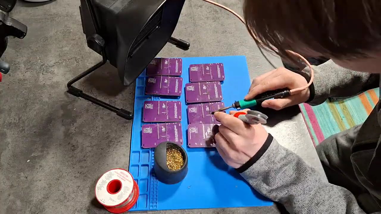
WashTastic is a meshtastic node with built in solar charging, battery overdischarge protection and a 1W radio.
https://github.com/valzzu/meshtastic-pcbs/tree/main/WashTastic
It sez it on da chip
Idk, those wiggles look pretty proprietary to me 🕵️
Not much ground pour, either.
Funny enough I'm already at 4 remaining of the 10 i got 🤣
Sold 5, used 1 for my node lol
I want a couple... As long as I know where to swap resistors for different battery chemistry.
Currently lithium only supported 😅 tho im thinking what to do xd
Either i make WashTastic into a modular system or just have few variations
What charge controller is it using?
Ah I can see it there. Nice.
V0.3.5 has 3791
Probably best to just keep WashTastic as one module and just have few variations xd
Time to make cn3795 version 🤣
I honestly don't know the difference between the 2.
Ahhhhh makes sense
Is 3795 the same pinout and size?
Nope 😅
Tho it shouldn't be hard to add it to WashTastic
Its literally almost the same
3791 is 4.5V-28V
3795 is 6.6-30V
Thought it was bigger difference
Nvm
Both are 10pin ssop
Aha
So they removed the charging done led to gain extra pin for the chemistry selection
I do need to reading the chip area lil bit tho xd
Everything else should be fine left as default, tho can't use the battery protection chip tho 😅
Won't work with anything that goes below 2.9V 🤣
Pr over 4.2V
Hmmm yeah. Or just add a jumper to disable protection?
True
Probably could have a version done tomorrow or something 🤣
Autopoieesis and me have a custom cutoff circuit .
Takes a lot of board area, and is pretty complicated to make it not waste power
Dang
But can do high and low cutoff at whatever voltage you want
Cool
I'll find the part later on...
So in theory i could make a array of resistors like on mppt selection to have different voltages definable by end user
🤣🤣🤣
I think ahe programmed it all in Atopile, which doesn't help either of us.
I think you can take the repo, make some changes, commit it and the GitHub actions compile it, but idk
Dang
She answers questions better than I can 😄

but then you'd need balancing, no?
Yeah, I was just being an ass.
i wonder how keith did the balancing since this has 3 pins

one ground and 2 positivie
dont see 3 pin connector here


I don't believe he did - he figured 2x cells from the same batch would age similarly together.
But I'm sure captain cap was saying something about using capacitors and resistors to do balancing if we really care deeply about it.
but do we?
I don't know. I think the main risk is over-volting one cell if the other goes short-circuit?
I did wonder about using an ina3221 to monitor this stuff.
Like, use one channel for top-voltage and current shunt, and then another channel for middle and bottom voltage.
And then a conventional low-side cutoff can still be used.
now i gotta fit some resistors in here somewhre 🤣

Is that solder dispenser pen any good?
Pretty good in my opinion
Manual or powered?
manual haha
3d printed
there we go 🤣

tho i do now need to change the mppt values
Link? 😄
lemme see if i can find it

Printables.com
The Solder Scroll allows you to easily add solder of different diameters. | Download free 3D printable STL models
xd
ive gotten so used to it that when it runs out and im lazy to refill it i dont know how to use solder anymore 🤣
cuz its so thing
Me here using 1.2mm solder cuz I'm too cheap to buy the thin stuff
i stole my dads solder xd
Full of lead? 😋
it indeed is leaded
Sweet
values have been updated

some values are rounded up/down 😅 for the text
like 10.3V or 20.6V
prob better to round up with this
there we go

are those common solar panel voltages?
like, what setting do I pick for a '12V' solar panel? should I measure the open voltage of the solar panel
for 12V u select 11V
etc
if open voltage doesent go above 30V u good but ye working voltage of 12V u choose 11V
ill list the actuall voltages those set points are 😅 they are lower what is displayed
acording to resistors
21V = 20,5V
16V = 15.7V
11V = 10,2V
8V = 7,4V
7V = 6,4V
thats what the chip will expect atleast
technically the voltage range is 6.6-30V but min 7V is probaply more reasonable as the min
like keiths board
so then does it work with a 5V solar panel?
I'm a bit confused to what the 12V in 12V solar panel refers to
V0.3.5.3 works with 5V panel
0.3.5.3 damn what a version number
yes
are there any imperfections in that version?
only one, the promicro might not boot on solar only. i didnt notice this but @true garden did also they checked it with oscilloscope and there were some ripple on the battery line when no battery was connected. worked fine with it connected tho
so lets say u have 5.5V panel i move the 5V dip since its the closets.
7.5V u either move 5V or 6V dip 😅 it works down but not up xd but for maximum efficiency u should move 6V dip etc

did this help?
ill add some caps to hopefully help with this
yeah that makes sense
do you have like a lineage graph to trace what versions originated from what other versions?
to the version that can handle 5V?
ye
ill just need to figure what caps 🤣
well i did get some recommendations but one of the caps i cant add even if i wanted i think
i can try lol
but ye
ill add some caps maybe tomorrow
why did you update the voltages of the MPPT? I don't get the reason behind it (except maybe more optimal voltage for a smaller voltage range of solar panel?)
its a diffrent chip 😅 it now has cn3795 that is multi chemistry
3791 is just lithium
so thats why
ah, I see, makes sense
And the dip switch silk screen
He’s testing one in hand ? Or thinking about ordering ?
thinkig of ordering i assume
The worst part of building is getting the stupid kapton tape off the dip switch
agreed
yeah, I'm thinking about ordering one, but was waiting for the hardware feedback to come in once people had a board in hand
I'm happy I waited 😉


You could always ask for pin headers and a teeny lil jumper.
Old school styleee
It’s not a big deal it’s fine once it’s done
It’s just difficult to get the tape off easily
Tweezers?
It’s just funny that it’s the most difficult part of building it
More kapton?
What is a joke? Meshtastic is serious business.
serious
It’s very difficult to get under

alr it has been pushed to github
@remote jungle Ur probably fine ordering
There's 4 boms 😅
2 with bme280 and 2 without
Also with or without connectors
Does washtastic restart by itself if the voltage of the battery drops too low and is then recharged by solar? I remember some boards having issues with that and needing manual intervention.