
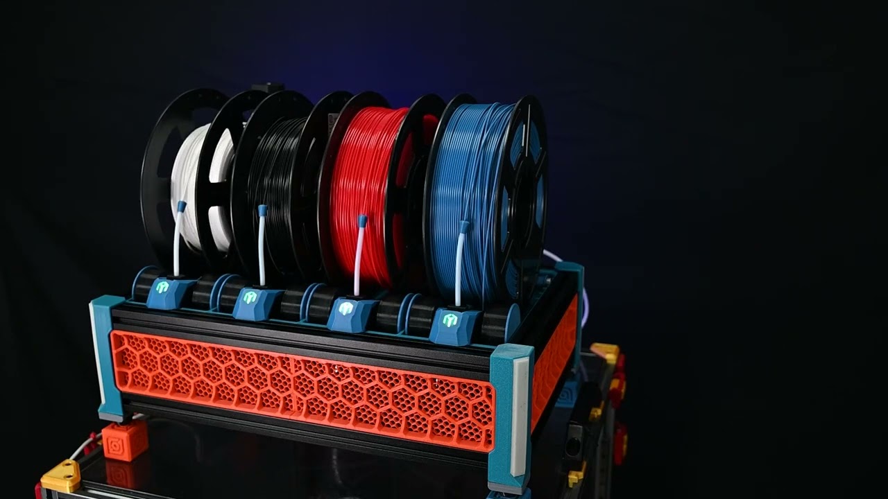
#WashTastic - 1W node based on E22-900M30S and promicro NRF52
1 messages · Page 2 of 1
might be abel to fit ina3221 in there

i still have stuff to do with the nrf52 chip too
like adding the leds
I like this concept of just rolling our own MCU, I'm glad you are smart enough to figure it out 👍
im not smart at all 😅
We'll iterate then until we get it right lol. This is a good step to get away from the RAK and Heltec boards.
and promicros xd
How do you like those SMD PH connectors? I usually use the through hole ones, but the extra support ones seem to me in short supply on LCSC. I've been thinking about using those SMD ones with the totally enclosed housings.
The through hole ph's with supports can be found on Ali pretty easily. I ordered 1:1 between LCSC and AE, and they came out almost identical.
No need to worry about them coming loose or anything like that
OK good, yeah I was worried if you managed to rip one off yet
the nrf52 chip can run on 5V but it needs to be connected to VDDH where currently the battery is connected, so i will just leave it at that.
so the charge chip should supply 4.2V when u plug in the usb hopefully
mmmmmm.......

much better

its just complaining about the smallest traces and vias that jlc can do
cuz i didnt bother changing the drc params
ppl are gonna like the addiitional charge 😅
hows that, ina3221 fits there 😅

not sure about that ble antenna
and added gps port
now theres text on the pins 😅

some components werent in stock so its missing some

tho this doesent have the fee for the tiny vias
not tax and shipping


How's the clocking done for the NRF52?

wdym
You've got a crystal on there
They're always a bit of a bugger - impedance matched traces, tweaking capacitors to match, etc.
🙃
just followed this

how ever did not follow this 😅

values are the same
but types arent
xd
sooo
if it works it works 😅
i didn't do anything fancy for the antenna so im pretty sure it will workish but how well thats a different question
@meager spruce V0.4 is now in github 😅 no clue if it works lol

I wonder will i be the first one to order 0
V0.4 or someone else 😅
And suffer when something doesn't work
Won't be me, I have enough incorrectly designed boards on order to keep me busy for a while lol
Might be me then 😅
Unless there's some random madman out there
For clarity, v0.3.3 is in perfect working order?
Did v0.4 get INA also w/ the rework ?
Whenever ill order 0.4 I'm gonna be real sad if it doesn't work 😅
Since its more expensive to produce than the previous version
Ya
I rly hope it just works 😅
Atleast the promicro part
I mean nrf52
I did also increase the boost to 5.5V
Max what the lora can take
So now maybe when theres a voltage drop now it stays at 5v or something
Higher than on the previous version
Is the goal 😅
You are mad but I love it! Take it you’re finally PCBA’ing the whole thing?
Also what boatloader are you going to run?
Supposedly the chip should have uf2 bootloader but if not its just the generic nice nano bootloader
Or the bootloader that was made by one of the members here
Probably the later one
I mean what does it look like 😅
I have no clue if it works at all tho
Can you point me toward this? I’m trying to build something off an E73 and this is what’s keeping me from smashing that order button…
Though with what you did here I kind of want to skip it and just send a BGA NRF52 lol

GitHub
Meshtastic device firmware. Contribute to meshtastic/firmware development by creating an account on GitHub.
If the chip doesn't have bootloader u need the .hex file
What are the 2 4pin headers for ? I2C for the one next to groove connector ?
I2c is next to the groove an the other one is gps
AH!!!!!!!!!!!!!!!
Groove is i2c also
Forgot you wanted to break that out..
I'm pretty surprised I managed to fit everything in the same footprint 😅
When you're only breaking out the pins you need, it opens up some space..
True 😅
So I have a solar panel I want to use w/ this, but it also has like a 1200mAh battery built into the panel.. Would that affect the "solar" charging of this ?
Its gonna be funny when it shows promicro diy to ppl on the mesh 😅
It really is a DIY now, tho.. ;P
Should not Afaik
I'm gonna JST the wires, and give it a try.. Still need to figure out an enclosure for it..
Btw v0.4 power directly from usb 🙃 well... Vbus goes to the charging chip sooo... It kinda powers it lol
But if i was u i would not order it yet 😅
Untested
And more expensive to produce now
Ya
Just put together the second 0.3 board I have.. Didn't fix the issue w/ the IC that needs to be fixed.
Mmm
Huhhhh, did you take the guts of the pro micro and squish them in?
Not exactly but technically yes

Yes

GitHub
Most battery protection circuits allow the battery to discharge to about 2.5v, but the nRF52 halts at around 2.8v. Even after recharging, the MCU is still halted, requiring manual intervention to r...
Hmmm. Need to pull up the schematics again...
I'm not a massive fan of that e-pad being electrically connected - too easy to bridge.

Ooooh
Ye go ahead
I just remembered wrong then
It totally makes sense cuz it was me who fixed it not u
😅
Yeah, 0.3.1 was the BOM fixing, 0.3.2 was technical fixes.
Can you reopen their issue?
Done
There - replied with pics.
Can u real quick Check the pcb file, I just realised there might still be a mistake.
Via in the middle of the ic
Not sure
Nvm
Phew

Hey @olive basin ever thought of selling these on Etsy even if you still had it fully open source?
Is this you trying to get out of assembling or getting JLC to assemble for you? lol
Please sell these on Etsy 🥺
Oh yes i have 😅
No, it’s easy for me but I know for other people
I’ve been selling a couple 3d prints on Etsy already
Dumb question, but what size JST are the connectors ? 2.45 or 2 ?
It's ph2
Tho this happens after i get out of military at somepoint
At somepoint i will 🙃
Tho not sure how id do it
Is it preorder or do i have some in stock 🤷♀️
You could just have some in stock and then ship them out with the pro micros on them
One day I will explain the concepts of inventory cost, working capital and cashflow. But not today.
Mhm
No promicro after v0.4 is tested to be working
If we go by v0.2, 10x costed me about 200€
V0.4 is gonna cost more
5x Mikoto cost $100+
5x pro-micro cost $15
Yup 😅
Soooo.... Maybe i will stock some but who knows
Maybe I'll start with preorders
And if this is popular I'll consider having some in stock
🥳
Pre-orders would be the best way to go, to start..
Indeed
Could form a network of community hardware sellers...
Mmm sounds good 😅
Idk what that would do but im in xd
Soooo... When? And how? 🤣
It’s not that hard to sell on Etsy but the fees are a lot
Wasn't planning on using Etsy i think
There's a few on here seem to do Etsy, but fees start at 10.5%, at least for me
Tindie is slightly better, at around 9%
eBay charges flat per-listing fees, but are notoriously notorious
Kofi and Buymeacoffee both allow product sales, but have no real backend
Patreon?
-# onlyfans?
Any others?
I was thinking of using fourthwall, i do have patreon too.
🤷♀️
Plus my twitch subs get a small discount on fourthwall 🙃
And they take nothing on products i sell 🙃
Physical products
What do you stream on twitch ? I used to stream my Voron printer.. LOL
Ummm.... Anything i feel like 🤣 mainly video games
Sometimes some diy stuff
Anybody able to tell me what the shipping estimate shows?
https://iris-the-elf-shop.fourthwall.com/products/washtastic-meshtastic-compatable-radio

Iris's not so fancy store
NOT ACTUALLY FOR SALE YET,
THIS IS JUST FOR TESTING PURPOSES!!!!
1W radio compatible with meshtastic.
No shipping estimate showing..
Not even if u add it to Ur cart and proceed?

Shipping from you to me via their selected carrier?

That is rly expensive shipping 😅


Neve 🙃
Hmm.....

I could set fixed shipping rates, however i can't 🤣
I don't have fixed rates anywhere
122€ in incognito mode 😅
Ummm.....
I asked about it in their discord
I'd try to help, but we don't have service in finland yet..
I have to think about what to use
Not sure if Shopify could work 🤷♀️
Idk
Never rly sold anything
I mean i can ship domestically pretty cheaply so 🤷♀️
Last time it was 11.50€ when i shipped few WashTastics
That's fully insured 24 hours, right?
Nope 😅
Tho that was from the postal office
I could get it cheaper if i paid online

Okay, someone suggested to include the shippin the price
So take avarage shipping price and add that
Might do that
Haruki 🤣

🤣🤣
U won't be getting anything tho 😅
I mean i do have have 4 spare nodes i think 🤣 but free shipping naaah 🤣🤣🤣
If u wanna press it go ahead xd
According to chatgpt, avarage shipping in EU is 21.40€ so ill round it up to 22€
For small package
After wiring up a 1.25 to 2.0 JST adapter, I have both Washtastic nodes running at the same time.. Now I need to figure out the best option for enclosure, 3D Printed, or project box..
I've done both...


that rly looks good
What filament and printer ?
Bambu X1C, Bambu PETG-CF Black
The carrier board I just blanked out and manually drilled the mounting holes
Ah, I only have P1S, and I might have PETG-CF from bbl..
Wish I would have bought a X1C instead, but they are $$$$
That's kinda beautiful.
Me: prints 9 prototypes, not happy with any of them.
@meager spruce blanks holes, prints once, drills once.
Carrier boards are easy to work with. Enclosure was made for a Rak, but I've successfully put three additional variants of nodes in it
Oh ye the new tariff stuff
U can just order this 🙃
Files are in GitHub
That's what most ppl here did

GitHub
PCBs i've made for meshtastic. Contribute to valzzu/meshtastic-pcbs development by creating an account on GitHub.
Shipping from here to US is ridiculous
Tbh anywhere outside Finland is more experienced
Tho i will be selling these at somepoint
Its not hard :)
Haruki?
What about haruki?
https://jlcpcb.com/
Just download the Gerber, bom and pnp from GitHub
Industry-leading PCB prototype manufacturer,offers 24 hours Quick Turn PCB prototype, PCB assembly and Reliable small-batch PCB production.
Don't download the v0.4
Its not tested
On the home page click add gerber file
And then choose pcb color if u want something else than green
Then enable pcb assembly
After that hit next or whatever it was
And add bom and pnp file
@arctic mist
It might complain about some missing or out of stock components
Just let me know what they were and ill see if they are needed
Np
V0.4 is the next step on this node but i have to first test it before i can say its ready for production
Plus tax 🙃
When u go to payment
I paid about 200€ for 10x
It was v0.2 tho
Oh ye thats only pcb, not assembled

Ye thats good
Don't worry
U also need to get these
https://a.aliexpress.com/_EwVZm72
Thats fine 😅
Its just a connector
Groove
I'm not toooo worried about ordering the pcbs, but making sure the dev board and radio module go onto it without issue...
V0.3.2 works, v0.4 no clue 🤣
Im novice with pcb soldering. Only ever soldered wires and connectors
Im scared of pcbs 😂
If u order with assembly only thing u need to solder is the promicro rly
US?
I will have to bug someone living there if he wants to sell these there
What enclosure is it ?
US, yes.
I mean I'd love to learn. Might look into practice kits for pcb soldering. Big difference on just wires and connectors(dumb components), and lot less concern about frying something like resistors, sensors, etc


Hardest part is deciding what type of connectors to use.. LOL
I used normal header pins for 1, then round headers for the second, so I could swap the promicro if needed..
I didn't like having the long pins sticking out of the bottom of the board so much. That's why I did the round headers.. Ended snipping off the extra on the header board..
https://www.printables.com/model/940298-rak19007-radio-style
https://www.printables.com/model/928913-meshtastic-rak19007-wisblock-case

Printables.com
Modified for increased gps range, power switch and slightly lower antenna placement | Download free 3D printable STL models

Printables.com
Case for 10,000mAh Meshtastic device. | Download free 3D printable STL models
I have a 5000mAh on 1, and a 3000mAh on the other..
AH! I'm looking for more of a solar enclosure setup..
Will probably make a quick v0.3.3 today or tomorrow :) small changes
Like removing groove from bom etc
Adding holes where u can solder battery or solar 🙃
I hate groove so much.. LOL
 right after I order 0.3.2
Like v0.4 has
So who's gonna bite and order v0.4 ? LOL
...why? its a standard. doesn't mean you HAVE to get those connectors lol
Don't worry, if nothing i will do it.
At somepoint
I use a general 4pin PH where Grove are needed, and then I can use both connectors. just the Grove needs to go in upside down
It's a shit standard, since you can't buy the connectors to make your own cables, from what I've found.. A normal 4 pin JST would be much better to use, rather than making a new standard, when one that fits was already available..

They're HY connectors with the clip snipped off lol
So not a standard connection..
If I have to modify a connector to make it fit, it's not a standard.
its a proprietary connection, lol i just find ways around it.
It's a pritoritary connector..
im more in favor of it for the pin order vs the connector.
i wish the pin order was an i2c standard, the connector can kick rocls.
That's all I'm saying. The connector is pointless, if there is already a standard.. There sadly is no standard pin order for I2C, which is what really screws everyone..
like some of these board makers do GND-SCL-VCC-SDA.... FFS Why!?!@#
This with the WashTastic + my credit card/Venmo = your profit 📈 👌
😅
Wheres my cut? /J
it wasn't fun to put together lol and i REALLY wish there was an external switch/user botton so i could disable the GPS. So I likely wouldn't be doing another.
Whats your Venmo?? 🤣
V0.4 has gps power switching, tho no button to disable 🤣

Even managed to fit that to the 31.8mmx31.8mm board 🙃
It is connected to the nrf chip
So software can control it xd
i thought the software needed input to turn it off?
Ummm... Possibly
Actually it didn't bur now it does
It was turned off when u had gotten a lock
And position
Ill add a user button to too 🤣
User button X3?
Can't the user button be used for that ?
Sounds like a feature request lol
i could "make" a user button by soldering straight to the board, but the case i'm using doesn't even have a spot for it
just please no side buttons, those always break off 🤣
give me pads and I'll make the rest work lol
You have a drill, don't you?
If you saw how thick this thing is, you'd understand. I don't want to compromise the integrity of the outer shell for it: I may work some magic on the bottom plate where the USB port is
Sounds like a job for a reed switch 🧲
LOL Duh.. That's right..
there

pushed to github :)
also made it so u can get it assembled without the connectors
tho had to sacrifice one screw hole for user button
I feel like you could shove a lot of the exposed stuff under the promicro if you wanted.
thats true 😅

same goes for under the pcb
maybe ill put some uart pads there 🙃

Any solder contacts would be best on bottom, since there are no components during build..
As u see i added 🙃
Yup! All you need to secure, is some yellow electronics tape, and hot glue
What are the 3 "middle" pins for anyways ?
Just extra GPIOs on the promicro ?
Yup
k
Theres and ic under the promicro
Well ldo
It can be nice to add a rocker or something to them
Canned messages 😅
Speaking of thay hmmm.....
Any small rocker i could use on the watch 😅
Would have to go under the pcb sadly
Aka manually soldering
Like a power switch to kill the power completely ?
Strange regular voltage drops self-reported by washtastic/nrf52 3.1 with inactive on-board batt protection but built in protection within the pouch battery. It's running with a 5000mAH battery (half full) and on solar. Are these drops from drawing 1.7A while transmitting? This does not look that good / in-stable I guess. I don't see any reboots though.. Any thoughts?

even on the lower power boards, I see big dips
I suspect its partly due to the battery curve being generic, and having a huge cliff built-in
I was more thinking an up/down/select switch
.... like a CN3791 with 5V/ 12V / 18V solar charging option. Might be useful for this board with higher energy consumption than other (rak) based boards. If we solder the nrf52 on headers / removable there is lots of realestate underneath. But I am also ok to use one of these dirt cheap CN3791 boards separately.. Sure it's not possible to cater for all use cases. This is called in German "Eierlegende Wollmilchsau" - I am sure there is a similar word in Finish...
V0.4 no longer has promicro 🙃

anyway there rly isnt much space either way for cn3791
this is all the stuff it needs


altought some of thos components can be changed to smaller sizes
and that has some extra components that washtastic already does have
Thought you had considered moving from Grove to Qwiic to save all that realestate?
i was thinking of moving it on the bottom but 🤷♀️
not sure
even if i did change it for smaller it would not affect much
now V0.4 has user button

There is a power switch already
Anyone have an enclosure for this board yet ? I'm janking it right now, so need some extra space for 2 of these beasts, right now..

@silver crest was it u who made a case?
You can use wago 221 and save some space.
I don't want to have to spend any money right now.. Worse case, I can shorten the jst cables, and use solder heatshrink..
Yeah, but these are wagos. You buy a box, it'll last a lifetime.
Wagos my beloved

Oh trust me I know.. I need them to upgrade my voron v2.4, I just don't have the spare money right now to spend on them..
I work with what I have till I have the funds to get what I need. That's why it's janking..
I want a voron 2.4 🤣
Get a Trident
Looks like their 3-spindle but otherwise conventional corexy
The flying gantry thing is very complicated
Save yourself! You've already got a 3d prjnter
Naaah, i want corexy xd
I went from corexy to bed slinger.
Zero difference
Well, except my unfinished voron was pushing £800 and the Neptune 4 cost like £200
Modern bed slingers are different breed 🤣
Anyway, i do want a more reliable and more up-to-date printer xd
Then a self built voron is not it 😉
DIY printer is a learning experience, but it is a license to tinker
Haha
Anyway i do want a better printer what i currently have 😅
Even tho it has done its job fine
Not including Small hiccups
Trident has 3 point bed leveling, the nozzle stays in place, and the bed moves up and down. VS v2.4 the bed is mounted at bottom, and nozzle moves up and down.
Trust me, you want a Trident over a v2.4
I have a Trident kit, I still need to build..
Also, if you want multicolor, go w/ a Turtlebox, not the ERCF..
👍


⚡Watch the build from start to finish here:
https://www.youtube.com/playlist?list=PLQRtgQ_nyr-uyUFT32GH4ivC_muipna3w
Watch as we build the Box Turtle, an amazing multi-material 3D printing marvel by @Armored_Turtle-RK This project is the perfect way to spend a chill Sunday. 🐢 #3ddruck
Box Turtle GitHub - https://github.com/ArmoredTurtle/BoxT...
Sorry, BoxTurtle..
This is prolly a better video.. https://www.youtube.com/watch?v=SZF6mm9Z6wc
BoxTurtle is an advanced, open-source AMS-style automated filament changer developed for Klipper-powered 3D printers, tested with VORON Design printers and other Klipper-configured machines. Designed to simplify multi-material printing, BoxTurtle delivers a seamless filament changing experience for an accessible AMS-like setup.
This is a DIY Ki...
👍
Think of it as the BBL AMS but for Klipper based printers
Yee
Here is an overview from Armored Turtle.. https://www.youtube.com/watch?v=AP_XsKV063s

A quick overview of what BoxTurtle is and basics on how it operates.
More info and links to kits are here:
https://github.com/ArmoredTurtle/BoxTurtle
Reach me [email protected]
I have like 14 3D Printers..
If you can, go 350mm
And if you have an Ender 3, you can convert it to a switchwire..
I got anycubic mega zero 2 😅
Ah
What kit do u recommend?
LDO Kit for sure
Was just gonna say xd
This is a rough list of what printers I have..
EZB = Ender 3 v1, EZBoard Lite 1.3, Stock hotend w/ titanium heat break, hardened steel nozzle (removed), EZABL, Caricorn PTFE, BMG, PEI bed, Silicone bed spacers, filament runout sensor.
v2 = Ender 3 v2, Stock v4.2.2, Stock hotend, BLTouch, Red dual gear metal extruder, Caricorn PTFE, PEI bed, yellow springs, filament runout sensor. - Given to niece
427 = Ender 3 v1, v4.2.7 mainboard, Stock hotend w/ titanium heat break, BLTouch, BMG, Caricorn PTFE, PEI bed, yellow springs, filament runout sensor.
E3Pro = Ender 3 Pro, Duet 2 SBC, v6 hotend, BMG extruder, Dual Z, BLTouch, Caricorn PTFE, PEI bed, yellow springs, filament runout sensor, running Klipper.
BX = BIQU BX, H2 hotend w/ titanium heatbreak, stock inductive sensor. stock spring steel, stock dual z
E5+ = Ender 5 Plus, Stock hotend w/ titanium heatbreak, BMG Extruder, yellow sprints, glass bed, running Klipper.
BX-2 = BIQU BX, H2 hotend - Unbuilt
M3D = M3D Crane Quad, Stock - POS
CR10 S5 ? = AC Bed, Copper build plate, EZABL, no clue about anything else
Trident = Voron Trident 300mm with ERCF 12 - Unbuilt
SV01 = Sovol SV01, Stock, running Klipper.
Prusa = Prusa MK3S, E3D Titanium heat break
v2.4 = Voron v2.4 350mm, ERCF 9, Watercooled dragon ST, West3d magnetic bed, Lucid probe 24v, sexbolt z-endstop, Ribbon cable mod (FFC), rPi Screen mod
P1S = BambuLab P1S, 2x AMS, 0.4 Hardened Steel Nozzle, Hardened Steel Gears, Panda Touch, Panda Jet, X-Touch w/ chamber temp, spare parts: 0.2 nozzle complete, 0.4 nozzle, 0.4 nozzle complete
Don't move house...
Lemme see if I can find you a good 350mm kit
@olive basin See if you can see this.. https://www.siboor.com/product/siboor-voron-tridentjune2024-cnc-metal-structure-4awd-corexy-all-hiwin-rails/
If you were in the US, I could give you a good one. Let me check the voron discord for any finland resellers..
Ah, ok
I've ordered so much shit that doesn't come from Finland 🤣
Can you order from GB ?
Different thing is, will i need to pay custom's fee/tax when it arrives

www.hotend.eu
Voron Trident R1 Pro is a 3D printer kit designed for experienced 3D printing enthusiasts. This version with a workspace of 350x350x250mm offers excellent print quality and high flexibility with the ability to modify and upgrade the printer.
Experience the Art of Precision and Excellence Notice: Ships within 20 days unless otherwise specified. Key Features: VORON Tap Kit integration VORON Stealthburner integration EBB SB2209 Canbus toolboard, ADXL345 integration CNC machined Cast Aluminium Buildplate, flatness <0.15mm Full-size Heater, it won’t warp your buildplate anymore MOONS...
@olive basin The last link was recommended by ppl on the voron discord.
Thx
Just remember you might need printed parts in addition to this kit..
The voron discord does have a PiF channel, where you can get pricing from locals that are approved to print quality parts..
Will have to join once im ready to get a voron
I sent you an invite. if you join now, you might be able to get more info on kits before you buy..
LDO has BoxTurtle kits, FYI..
Annex Engineering is another CoreXY printer you can look into, so is ratrig
👍
A v6 nozzle is fine to start w/, but there are much better options..
Dont want fine, i want good 🤣
If I'm spending close to 1k on a printer i want it to be good xd
Exactly
I upgraded the system to canbus, and a bunch of other things..
It has a water cooled hotend, allowing me to print any filament I need or not need, also.. LOL
Mmmm
So then I built a watercooling system for the onboard rPi.. LOL
Haha
Off topic photos.


Ill allow it xd
This is the printer I was talking about that I stream on Twitch with..
Nice
When it's running.. I had some issues w/ it, and haven't spent the time to fix it.
And now I have a P1S w/ 3 AMS..
If you're going into Voron kit territory look at the VzBot, don't touch my Vorons since finishing the Vz except the Ender2->Switchwire which is still slow but a set-it-and-forget-it champ at PLA.
Hmm
Yea, forgot about VzBot..
🤷♀️
Because you don't have a shower until you finish the project
makes sense
Too focused, too much passion

Man, I really don't want to have to make my own enclosure for Washtastic.. It's gonna be a shitshow.. LOL But looks like a 50mmx60mm box would work..
Maybe a 65, to add space for the sma jack to be mounted solid. Then just need holes for USB, bat, and solar..
Oh, I guess groove port might be a good addition..
@olive basin Do you have a basic case that you design for it or no ?
Nope, theres no case
Ok, I'm in tinkercad, trying to make something.. Do you happen to have spacing for the buttons and JST ports ? If not, I can try to get them..
I don't 😅
I've got 0 knowledge of CAD design, etc..
So it's gonna be a basic b!tch case.. LOL
Should have started on this on friday... 😦
@olive basin do you have a cad file for the board I could use ?
Unfortunately i do not
And cannot make one
Oh bummer.. ok..
Hot off the P1S.. Looks like crap.. Need to add supports think.. And maybe make the sides 2mm, rather than 1mm..
Welp, that didn't fit...
Make the sides like 3 or 4 mill will help a lot with bridging over gaps
Still need to make bottom thicker, and add screw holes.. But trying to get the layout down first.
Printingin PETG also, so that doesnt help.. LOL
Round 2
Pla for practice!
I know. That was just me being lazy, not wanting to dry and swap filaments.
Pla > petg for hygroscopicity
I've heard people having to print from the dryer for petg
If I had at least ol1 of the 2 additional AMS I have connected. I wouldn't have to swap as much.. LOL
Yea, thays normally how I print, with my prusa. Might just got back to that. Prusa is a champ..
Bambulab filament changer.
Holds 4 spools of filament, and swaps them.
I have 3 of them, so I can technically do 12 filaments.
Mine cooks for 2 days minimum before even getting put into the AMS hopper. ABS/ASA/TPU/PC all get printed from the dryer.
I've had a roll of pla on my printer for 3 weeks. I should wrap it up...
That PETG spool has been open to the elements for a few months and was in the dryer for about 20 hours before I put it in the AMS. Prolly need to dry it more..

I'm getting there! I think this print will be the one..
I'm printing in PLA now also.. ;P
only on my 4th print.. 2nd PLA print..

Nice
So I just unplugged USB cable from one of my washtastic boards, and it's no longer on.
Interesting. I had to turn to switch off then back on for it to power back up..
Battery is at 93%
🤷♀️
God dang, somebody dmed me on Reddit asking how to get my node 😅
is the v0.4 tested already? is it cheaper in total cost compared to the older version that used a separate promicro?
Just got these today!! Up and running


We're all too scared. Waiting for @olive basin to at least try it first lol
Pretty much..
If I had money to blow I would do it.. at least the radios wlare worth something you know.. LOL
@olive basin this needs to be a p-mosfet, not a n-mosfet 😦 #1194757507013427250 message
Not tested and its more expensive
Oooohhhhh...... Niceeeee
4 layers plus tiny vias
Fun times lol
OOoohhhh tiny vias.. So scary.. LOL j/k
I was doing 48 wire mod chips on the original xbox when they first came out.. Hair size vias, have to use a fiberglass pen to get them, then a hair solder tip..
Not even gonna talk about the encoder legs you had to do..
Sounds like fun
It was TOTALLY fun....... In a masochist way..
there you go..
That's an example install
That's not the same mod chip I used to do, but close enough to wire count..
Mmmmmm
Btw, u got a multimeter? If so could u check the 5V rail what voltage it is. Should be about 5.5V
Yea, I can check tomorrow after work.. I'm getting ready to head to bed.. It's after 9pm here.
and I have to be up at 5am for work.
BTW, How is it in the military for you ? I was a Chinook helicopter mechanic when I was in..
Wasn't to u :) if the board is V3.3 its 5.5V prior version were 5V
It was great untill i was told i have to follow my current units weekly plan this week and not goto my assigned role
Ofc I'm gonna try to get some exceptions lol cuz my knee isn't in the best condition yet, its healing but im not gonna make it worse
That's the military.. Voluntold what to do..
And theres literally one person now running the thing soon 😅 idk what the higher ups were thinking
What are you doing ?
Running an inside simulator and sone other stuff
Taking down Russia ? ;P j/k
Our sysadmin is on holiday and im the only one whos trained tobe the next one soooo...... Ye 😅
Oh those are fun days.. LOL
We have 3 ppl total from new recruits and the old one had 5 🤣
I'm 1 of 2 Network ppl for my company, we rotate oncall weekly..
Ill try and do this tomorrow.
I added a GPS, what should the GPS Receive GPIO and Transmit GPIO be?


Were they big enough to solder onto?
they wernt tooo bad.
I can make them bigger if need be
This is whats said about v0.4

having issues with the GT-U7 GPS. Meshtastic isnt picking it up for some reason.
DEBUG | ??:??:?? 69 [GPS] Trying $PCAS06,1*1A (ATGM336H)...
DEBUG | ??:??:?? 70 [GPS] Trying $PCAS06,1*1A (ATGM332D)...
DEBUG | ??:??:?? 70 [GPS] Trying $PAIR021*39 (AG3335)...
DEBUG | ??:??:?? 71 [GPS] Trying $PAIR021*39 (AG3352)...
DEBUG | ??:??:?? 71 [GPS] Trying $PQTMVERNO*58 (LC86)...
DEBUG | ??:??:?? 72 [GPS] Trying $PCAS06,0*1B (L76K)...
DEBUG | ??:??:?? 72 [GPS] Trying $PMTK605*31 (L76B)...
DEBUG | ??:??:?? 73 [GPS] Trying $PMTK605*31 (PA1616S)...
DEBUG | ??:??:?? 73 [GPS] Trying $PMTK605*31 (LS20031)...
WARN  | ??:??:?? 75 [GPS] No GNSS Module (baudrate 9600)
WARN | ??:??:?? 75 [GPS] Give up on GPS probe and set to 9600```Calling it a night. I check back tomorrow.

Note that gps_tx means the tx from the GPS etc
Gotcha
u may also need to flash the nrf52 chip with a bootloader.
It doesn't matter which one? And there's a chance I won't have to?

Wut 😅
I can use any bootloader I want? Like the Xiao one should work?
😅
No
Needs tobe for promicro i think
Thb
No clue
One way to find out
Xd
I would use the generic bootloader
The Meshtastic one
so if P0.20 is RX going to TX and P0.22 is TX going to RX
GPS Receive GPIO > 22
GPS Transmit GPIO > 20
no
other way around


thats what I had over night. And no bueno. This should support the GT-U7 GPS?
Would the HGLRC Mini M100 GPS work? Think i may order that and give it a try.
Try them both ways 🙃
Its going to be like plugging in a usb, 3rd times always the right way.

Mhm
still having issues, ordered the HGLRC Mini M100 GPS Module, it should be here tomorrow so going to try that.
Got the GPS working... So much soldering and unsoldering. I didnt use the pins on the bottom of the board, I soldered directly to the pins. I am going to try and move them back to the ones on the bottom to see if it still works now that I have it working and know it works. This is what I did and the settings that got it to work.
GPS RX to the NRF52 P0.20
GPS TX to the NRF52 P0.22
GPS VCC to NRF52 NRF52
GPS GND to NRF52 GND

Mestastic settings
position.rx_gpio: 20
position.tx_gpio: 22```Just put 2.6 on one of my Washtastic boards
Got it working on the bottom as well. Hope this helps anyone in the future!
GPS RX to the NRF52 RX (P0.20)
GPS TX to the NRF52 TX (P0.22)
GPS VCC to 3.3v (Back of Board)
GPS GND to GND (Back of Board)

Mestastic settings
position.rx_gpio: 20
position.tx_gpio: 22```What was wrong in the end?
Just typical troubleshooting…. Typically the RX goes to TX and TX to RX. In this case it’s direct. RX to RX and TX to TX plus the mapping out I put above in meshtastic.
Pass. The boost stuff is beyond me
Anyone put 2.6 on their washtastic ?
Nope - where to get it from? I surely have missed something here...
Read the announcement channel blog post.
@heady mulch
https://www.reddit.com/r/meshtastic/s/uxBLo6jLfI
Reddit
Explore this conversation and more from the meshtastic community
Washtastic node is up and running!

Was there a trick to getting it to run off the 5v input? For some reason mine works fine off the pro micro USB-C but it wouldn't power on with only the 5v input (yes, I did forget about the power switch initially but fixed that already 🤦🏼♂️)
Ummmm...... 😅 U dont. I think on v0.4 u could, not sure. Its also untested so not recommended
Ahhh haha no wonder. I feel dumb - just realized I should just feed 5V (off USB) into the solar port instead. Duh!
Uhhh oh. Just found out the hard way that I should've checked the polarity more carefully! I didn't notice that the smaller through holes for the battery (under the bigger U6 PH2.0 socket) are the opposite of both U6 and the the through holes for solar (+ on the left, - on the right). Definitely let out some smoke - I'll be more careful with #2 🤦
Might make a note somewhere for dummies like me (unless I just missed it) 😉


@olive basin make a note: more reverse polarity protection on the next iteration 🙃
Ummm... Wut
Oh
Oh
Shit
Thats not supposed to be like that 😅
Gotta fix that when i get on a computer
What case is that? Looks cool
Just a random "rugged" box I found on Printables and then drilled a hole in for the SMA. I'll see if I can find a link, just sec

Printables.com
Remix of my original Rugged Storage Box with a new snap closure and easy two-finger opening opening. | Download free 3D printable STL models
Wanted to double check if there are any recommended changes from the standard DIY pro micro/SX1262 settings. I didn't see any likely suspects but figured I'd ask
FYI the one that I got the polarity wrong definitely let out some smoke but still seems to work fine (and can still charge/run off the battery). Seemed like the smoke came from around U5 or R5 so may try to investigate further later with a multimeter if there are any obvious candidates to check

GitHub
PCBs i've made for meshtastic. Contribute to valzzu/meshtastic-pcbs development by creating an account on GitHub.
Tx power is what u need to change
Oh yeah, not more than 16 or 17 in the EU.
I always forget. I've added it to my Femtofox usb-config now, so it's harder to mess up.
Gud
What the chance of being able to swap radio to this ? E22-900M33S LOL
The 5v boost most likely can't handle the current
Rated for 2A
I mean it might 🤷♀️
Yea, it's a big boy radio.. LOL
it's working ok for me ¯_(ツ)_/¯
They need to remember to turn it down to TX power <8 or something, right?
8 for the M33, I think 25 or leaving it as-is for the M30S
Made a little mounting plate for a 4x4x2 Carlon junction box I'd picked up at Home Depot a while back


I including mounting holes for M2.5 screws (since the M3s I had were a little tight in the WashTastic holes)
Nice
WashTastic fixed i hope
@olive basin no idea if this is actually a good idea but you might consider flipping the + and - on the 5V through holes too (so that + is always on the right when looking at a JST socket from the nearest edge)


Solar is the same now, no?
@heady mulch can't find the message of the issue u pointed but this is correct now yes?

its how its in the image
But I see now it looks like you're constrained on the 5v with that mounting hole anyway. Sorry just wondered but sounds like not ideal to switch
What is the solar panel specs?
I think the mosfet is mirrored
So it needs to prevent usb power back-feeding the solar panel
But I can't remember.
max can be 6V iirc

i wonder if this is correct now

1M ohm?
prob
P=V^2/R
3mW?
Sounds better
aight
Just built one, it seems it's having some issue with low RSSI on receive
From 2 ft away Washtastic receives my other node at 50dBm and other node receives Washtastic at 12dBm
Tested with a diy Ikoka nano and a Heltec. Washtastic gets really high RSSI from both.

I wonder what it could be
I've tested a couple different antennas, no change.
Going to try reflowing the solder especially around the ground pads of the E22 and see if that makes a difference
Ur the first one to report this so don't know if this issue is only for u or is it for everyone
My best guess would be bad solder joints. I had JLCPCB do everything except the promicro. If that doesn't work I'll try replacing out the E22.
One thing I did notice while comparing the two boards, the Ikoka has a lot more stitching vias compared to the Washtastic.
Maybe that might help, but I'm talking out of my ass here and have no technical experience with PCB design
@olive basin you're using pin 0.17 for Rx switching, right?
Might be stuck on Rx mode or something
Ummm... The one that is listed in the config iirc
Yeah, just think of sources for the problem
Or a bad module.
That too


Oh, i see how u soldered the promicro
U might have some contact issues :)
The radio module looks good
It's hard to tell but promicro does have pins going through the holes
Oh theres pins
If I post my basic bitch case, can someone please take it and make it better.. LOL
I rly should have some sort of a place where ppl could upload images of their builds made with my boards 😅
@alpine epoch @heady mulch ideas? 🤣
here would be good
they just get lost here 😅
Here then maybe you choose the ones to upload to GitHub? Maybe?
hmmmm....
question: is there a reason not to use the CN3791 instead? it appears that it's compatible with a lot more solar panels (up to 28V input)
please post what u have done with this here https://discord.com/channels/867578229534359593/1346425369246302258
i can change stuff tobe smaller but u can see how much components it reguires

is the PCB size constrained?
Price goes up above 100mm on a side
And some services charge by the PCB area
Question - I have a few bare boards I am thinking about trying to hand solder. If I don't need the 5V output, are there any components I can leave out (or is all of that needed anyway for the 5V that feeds the E22)?
The module works with 3.3v.
I guess u could power it directly from the battery too but u won't be able to get 1W
I mean u can make it as big as u want but it will get more expensive etc and id rather keep my nodes as small as possible
So I was not able to figure it out..reflowed solder on the E22 and promicro and also tried a custom firmware build. I'm assuming it's an issue with the E22.
Built a second one and it's working great
Exciting project. I’d be willing to pull the trigger on 0.4 if nobody has yet. Might make a few changes for my own power supply plans but otherwise this is an awesome looking setup.
Has anyone tried the more powerful 900M33S module? The boost converter might not be able to handle the amps but I would be powering with an external supply.
No one has to my knowledge.. For the radio, no one has. I mentioned it a few days ago also.. Was told boost would need rework.
Nobody has not tested 0.4
I wonder


is that someone you dont know selling your design?
I don't think so.
It's mine :)

Hey if it works it works
Pass it to me on a txt and I'll rewrite it.
Remind me in like 4 hours.
Yes hello 🤣
hihi
Yeee
how'd you do the battery management?
i'm working on a similar project and the hardest part is the battery
oop sorry for not responding. what protection circuit and what charging circuit did you use
tp4056?
i'm thinking of using a buck-boost to get 5v out of the battery
how'd you get both 5v and 3.3v?
i believe you need a seperate step-down and step-up
and 1W doesen't require a ham license in the US right? (i mean i have one anyway, but i would like encryption)
Charging is via CN3163, which is superior to the TP405x in that it can charge from solar without going weird.
Protection is from a XB8089D0 - LV cutoff occurs at 2.9V
It has a boost integrated to get the 5V for the radio.
The MCU has its own LDO for 3.3V
Pretty sure you lot are allowed 30db radio and 6db gain for total EIRP of 36db.
should be ya
i don't think i need the xb8089
because the battery i'm using has its own integrated protection chip
Does your protection chip run down to 2.5V by any chance?
not sure, it's just a little pcb integrated in the battery thingy
Anyway, pretty sure you can just bridge it if you're not bothered.
Probably a Dw01a, aka the tp4054 of the battery protection world.
😉
perhaps
We love this particular xb8089 because it cuts off higher, and on normal NRF boards it's possible to drain a lithium cell quite low.
I have a question, how many here is from EU? And is interested in buying these?
Not Europe but EU
@heady mulch do u have ideas?
https://github.com/valzzu/meshtastic-pcbs/issues/10

GitHub
Hey There @valzzu ! First off - thanks for creating this and making it open source! I have a few of the 0.3.3 version of Washtastic and they are awesome! I'm rolling them out in our local mesh ...
It wasn't reversed in the design
depends on how much the price + shipping is
35€ + tax + 23€ shipping since i have no idea what it actually might be 😅 that was the avarage shipping in eu
Maybe after i know how much it actually is i can reduce it.
Dunno. Do you have to old Gerber files?
I don't want to poke project history because it has so much of it...
i didnt touch the battery port between 0.3.3 and 0.3.3b 😅
neither have i done that since the beggining
so 0.2
I can see that you could swap the connection around, cos they're offset from the pads, but I was struggling to see that you had done that
its the same layout
Bad transistor?
Photo of their connector?
Ah, feckit. From now on just put a bridge rectifier on every connector.
nothing looks broken on the photos
so i rly don't know
it rly could be jlc thing
hmmm
i asked to get a phot of the connector
@olive basin I think we need to convince @dim kernel to make a Washtastic enclosure.. LOL ;P
🤣
You've got a reverse polarity MOSFET on the positive, and the xb8089 on the negative. I can't see how you can put a battery on the wrong way round unless it was powered on when it was connected.
Has the 0.4 cherry been popped yet ?

Being in the military isn't making you filthy rich ? ;P
Is it mandatory for service time in Finland ? Or Volunteer ?
mandatory
Ah
i only got bit over 6 months left 😅
I joined the army here in the US at 16.. Was in for just under 2 years, and they discharged me for medical reasons.
What's the mandatory time ? 2 year ?
6 months, 9 months or a year 😅 depends what u do
9 months is for special jobs
and i'm in one of those
OH! That's not that bad..
This is the same issue that burned me. The through holes on the battery connector are reversed polarity from the pads just above them. Not a manufacturing issue - the good news is that my board still seems to work despite the smoke


I believe this is from after you fixed it
i don't remember touching the battery port 😅
oh
ye
😅
nvm
thanks github 😅
and commit history

ye i had completly forgotten that
If I remember right, I got something like 210 USD a day.. This was in the 90s tho..
dang
I think mine burned up something on the pro micro bc it seems to work fine after swapping in a new one (and the pro micro that used to be on that Washtastic had issues in other working boards). You might mention that to the person who opened the issue on GitHub.

GitHub
Trying to order a batch of V0.4 boards from PCBWAY, ran into a couple of issues in the BOM... Part numbers for C26/C27 appear to for larger size (603 vs 402). Also a bit of confusion about BLE ante...
prob should tell that it might not work at all 😅
I think you should!
You need a status table on the front page saying which ones to use
Or a release of the correct files


Well, your most expensive PCB yet...
Yeah, those guys....
mhm
So this is odd.. I got a notification from Meshtastic android app, saying my board is at 2% battery, but when I goto the node, it says 31% still.
Intresting
Why’s it so expensive? What’s different about this new version than the older one?
Pcbway plus nrf52 is on the pcb itself
4 layers
I do don't recommend getting it
Its not tested
Plus it has ina3221
Stop stop! This sales pitch is too good. Where is your store page?
V0.3.3b doesn't have ina 🙃

The NRF MCU is $$$$$ from PCB manfs..
And yet only $ on a pro-micro 🤔
Yea
The keeb folk think they're old or reclaimed stock
But who has found a shipping container of 1 000 000 MCUs?
So at 23% now, android app still showing its at 2%..
Does the charging IC on anyone elses promicro get hot AF when the following conditions are met?
- usb connected
- switch ON position
- LiPo connected
No smoke but I can't hold my finger to it for more than a second
Never tested IC temps..
Yeah idk if it just randomly started or if it's been this way all this time
I've charged it multiple times and I by chance happened to touch the usb c shield and it was hot
Heat seems to be coming from the LTH7 module
No clue 😅
Its trying its best to supply enough current to sustain the whole board so yeee.....
Anyway
Idk
Trying to charge and supply the board with like 100mA idk xd
Or 300mA if boosted
Does not do it when the switch is turned off tho
Are you using PD usb c like a usb c to c cable or use c to usb a like for an old phone brick. If you use PD it will get really hot
the poor thing is trying to supply 670mA at 5V from 500mA max at 3.3V.

I am using PD, good to know
its actually trying to power it from the bat pin 😅
promicro doesent support pd does it?
Its got cc1/cc2 resistors for normal 5v operations, I think
Ye
Ok, so I let the node fully kill the battery. It ran at 2% from app notification for over 12 hours I think..
It died around 3am PST this morning.
Hmmmm... My DIY nodes run at 0% for like a day.
It may have been longer honestly. Not sure how to track it..
If you can find the nrf chip for cheap, you can send them to the pcb manf and they will install them..
What is the cost diff between v3 and v4 ?
Ummm.... 200 xd
I paid 200 for 10x
Euro's
And then that one person has $400 tho idk how many
You bought 10 v0.4 ? or v0.3 ?
I know 5 was around 120 USD for v3
I think that’s what I paid for v3
Ah, ya, pretty sure it is.. I don't remember which version I got from Jude now..
But it was def a 0.3.x
b is the newest
Attempting to port this board to meshcore if anyone is interested. Never done it before so we will see how it goes
I mean it should work lol
Just out of pure boredum, can an ESP32 be wired up to this board ?
yes
just follow the pin mapping through

