#Another Dimension
130 messages · Page 1 of 1 (latest)
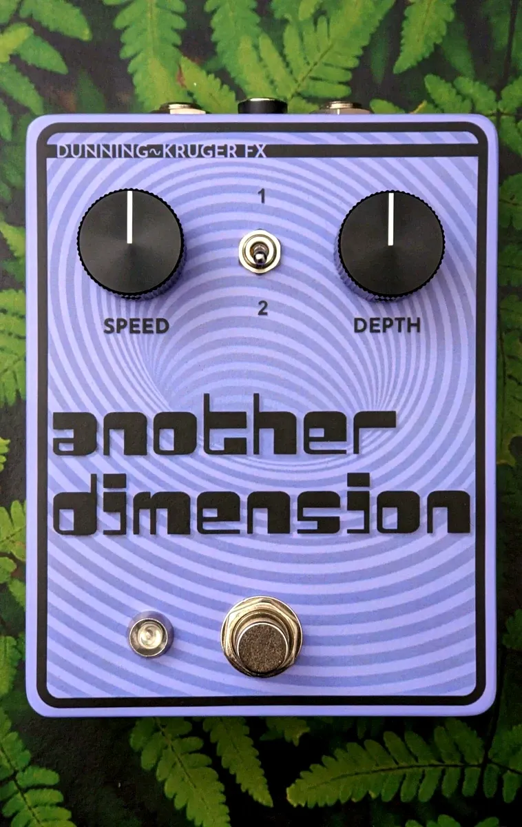
it's here finally! yayy
(yet) another dimension
the text looks like it's floating above the background, nice effect
It's the most believable version of a drop shadow I've ever seen. I didn't know MS Word had it in it.
well now don't reveal your dirty secrets like that
what am I doing with my life, I should read this now.
I think you know the full story of it already
it's always better to read it on your site
oh heck there's math
do you notice ohm's law hiding everywhere in the formulas you used?
No, should I have? Nothing I was messing with involved current, as far as I know.
I think the mixer is still wrong. I think the reason the slapback is so strong is because there are two wet signals and only one dry signal and they're out of balance.
but that's just a guess
I'm curious about that line at the beginning of "the sound" about it being farther from the ideal dimension C than the P. there's no reason this can't sound the same as the P, while improving on the other aspects
nah, just something that might be interesting
it's easy to have the same ratio as the P or the C, as long as you keep in mind that the pelota has some gain
Yeah. It's something for me to think about for v2. I'll have to figure out how measure that. Or maybe put in a blend knob or something.
i can help with that. otherwise, maybe the delay time is somehow different but i doubt that
hmm I was checking the layout and I can't see well what's been done with the spare op amp half
The extra opamp isn't used
but which is it in the layout?
tying it into a buffer with a jumper might avoid negative effects
I'm not at my computer now. I think it's the right half on the second board
oh i see there's a sneaky cut, I like to decrease alpha when there are cuts under components. it should be easy to slip a jumper where the cut is, or just bridge the pins on the copper side.
can I share a no stick, rework friendly board insulation method? zip tie a piece of cardboard to the bottom of the board
I've listened to the demo and i liked it. I think the most important thing is that you actually followed through with the ideas i've thrown at you to the end, and that's not something that happens to me often
Yeah, I wouldn't have actually gotten there without the help. It sat on my bench in a non-working state for the duration of two other complete pedal builds
consider these two tips though
not the alpha one, the jumper and not using tape
Yeah, the tape is easy to fix.
even without considering the sticky residue, you might consider pulling the ICs and fets off before pulling the tape off for whatever reason because of the static discharge it can cause
I'm not sure what you mean
I don't think this is static-y tape. But I'll pay attention to it just in case
any tape is static-y, it has to do with it being sticky
I don't know what this means, regarding the unused op-amp: tying it into a buffer with a jumper might avoid negative effects
take a piece of lead, jumper out to - and that's already a big improvement. if you want you can also tie + to 5v or vref so it's buffering a stable voltage instead of whatever it happens to pickup on +
just as a comparison, as it is now the output is randomly jumping between 1 and 8 V depending on which of the two floating inputs happens to be higher
Oh, ok. I can do that
To be totally clear, you're saying that for the unused op-amp, I should quiet it down by:
- Connecting Pin 1 to Pin 2 (output to
-) - Connecting Pin 3 to Vr (
+to stable medium power)
yes, and that's how you would always treat unused op amps (if they have to be unused)
cool, thanks
I updated the schematic to show the terminated op-amp. I'm not going to actually do it yet, because I'm going to have to take it apart again.
I got a hold of some of these 🫢 https://www.experimentalistsanonymous.com/diy/Datasheets/HT8970.pdf
They're pin-for-pin to a PT2399 as far as I can tell, but with less than half the ram, and supposedly will do shorter delay times
that's exciting. and pin compatible is nice. that part number or series feels familiar but i don't remember from where. are they cheap or easy to find? if so they deserve attention
They went out of production in 2020, but there are some around. I posted this on another board and someone got curious about it and is sending me a couple to try. It looks like they're $5 each in the US
Banzai have some in stock but they're SMD ones https://www.banzaimusic.com/HT8970.html

Holtek Echo Processor. DIP16.
hmm, the datasheet not showing delay times under 2.2k/30ms is concerning though, even if you say it has half the ram. what did the 2399 do with the same resistance? 40-50?
something like that
Here they are in the US: https://smallbear-electronics.mybigcommerce.com/ic-ht8970/
the price isn't appealing. or if production for dip or everything? what other board?
I don't know, it's worth a try since this dude is sending me some
the pedalpcb board
Interesting these other chips have a higher maximum output voltage
For comparison of delay times

that's pretty active, I just don't like the idea of discussing an original diy project in a forum of a company selling clone pcbs. are you active on fsb? that's the only forum i know with a section explicitly for original designs
I'm not
Looks like the HT chips use double the PT resistance to get similar delay times
I got on pedalpcb when I was building a bunch of their stuff.
hm yeah, they're very different, the 2399 is in its last legs with the vco shorted to reach 30
it could be worth to do linear regression on the datasheet to find the minimum time
what does that mean? the output should be close to rail to rail and you can adjust the gain
supply is the same too
The PT max output in the datasheet was like 1.5v whereas typical max output for the HT was 1.8v
hmm nah that's not worth much
You guys read these datasheets so much differently that I do. I didn't get past the first page where it said
Applications
- Television
- Video disc player
- Sound equipments
Who would want their TV or "video disc" to have delay? And "sound equipments" is just funny.
you either scroll looking for a number you're interested in, or skip to the tables, the pinout, the internal schematic. the rest could be interesting but only if you need to know more
so who's going to do the linear regression?

no no wrong relationship
You want resistance to delay time rather than oscillator frequency to delay time?

Ugh fine, gimme 5
you're offering, i'm not forcing you

woah!


you had the 2399 data already? could have sent it
I typed it out from the datasheet
I don't mind the practice since I can't touch type numbers like I can letters
i can with numpad, with the number row hell no
I have a TKL keyboard so no numpad for me
They are wildly linear
the actual points bend a bit near the origin because the vco op amp saturates
what is the unit of the x axis? 10s of ohms?
kohm in the first i think
And in the curved plots it's oscillator frequency
oh. ok
@sage zenith anyway the reason for the applications in the datasheet is that you can fake surround with delay
Also here's your semi-regular reminder that since the clock frequency of a PT2399 is above a certain threshold you need to get it FCC tested if you're selling a device that contains one
I don't sell anything
I'll be honest I forgot this wasn't #🌐│general lmao
I only sometimes make my website read like a retailer's because I think it's funny
it's sad that it seems like most digital black box delay chips are more expensive than bbd reissues
They're about the same here. Although you also need a clock for a BBD which makes it like twice as much overall.
you can diy the clock with various kinds of oscillators, you don't have to use a specialized ic as long as you can generate two out of phase clocks
we've seen the electric mistress doing it one way, I've seen some using a 555
Ah, ok. I've never tried to fully diy anything with BBD. The only thing I've ever made was a pedalpcb Julia clone, and the canned PCB uses a dedicated clock. In that case the BBD and clock were $4.39 each. The last PT2399 I bought was $3.95 and that HT8970 is $4.95. 🤷♂️
the only other chips under that price on banzai are the 2396 which is like a stereo 2399, and the pt2387, which is a "3d effect chip"
I don't know Banzai. Is that more like a place for curated, guaranteed-legit components or Alibaba?
Banzai are like an EU Small Bear
cool
I was wrong about the 2399 prices...I actually got them for $2.40 from StompBoxParts.
I got those HT8970s. They definitely work, but it's not quite what I expected. It's just kind of less effect overall. If anything, I think it's less lush, not more like I was hoping.
This is off > gradually more and more effect > the big thunk indicates when I turned it down to single delay mode
@sage zenith has reached level 41. Congratulations!
I also forcibly shut down the extraneous op-amp and upped the resistor in the feedback loop of the mixer from 12k to 15k to get a little boost. It's much closer to unity now.
(there was previously a noticeable loss of volume when the effect was engaged.)
you still might want to adjust the relative amount of dry and delay
I kinda like it. longer delay times give a more lush effect, but from what we saw the HT chip can't go that low, it's still more than most chori
each delay line in the pelota is 3dB louder than the input. if you want each singluarly to be the same volume as the dry, that's the 1.4 ratio like 33k dry and 47k delay in the pelota. since you have two delay lines, you might want to halve the gain for each, making them 33k 100k 100k. then you would halve them all (and the feedback too) because 100k is where i draw the line. the happy place could also be somewhere in between, with the delay lines being 1.4x larger rather than twice. in any case, I don't think equal values would give the best results
you might think "oh but then what about the single chorus mode". you can better exploit that switch by having it move the resistor that fed the other delay line in parallel with the one you're using, which doubles its gain. if instead the optimal ratio ends up being a bit smaller, it would switch a different resistor in parallel to the delay line to compensate the gain
Thanks, I'll have to figure out the math. Although it's annoying to me that the math didn't work on my first attempt. In the original diagram, they were all 33k ("all" meaning dry, wet1, wet2, feedback loop) and it was distorted and/or too loud. I did math and it made it seem like the feedback resistor should be 1/3 of the others. I don't have an 11k, so I made it 12k, which I thought would give it a small (likely imperceptible) boost, but it was actually too quiet and I just had to bump it up to 15k. I don't know why that is, especially if each delay line is 3dB louder.
But yes, I've been thinking about the balance between dry and wet
you're assuming to sum three identical signals, which these aren't, add that's throwing off any more math you can do on it
oh, ok
I'd say the two delay lines should have equal gain, but the ratio of each compared to the dry should be either equal (considering the 3db so you need 1.4 less gain, 1.4 larger resistors) or half (-6dB) or somewhere in between (-3dB)
the important ratios are all 2 and 1.4
which thankfully can be approximated by e6 well
then you can worry about tweaking the output so it's the same as bypass
@sage zenith ha! here's where you stole the name from! http://www.muzines.co.uk/articles/another-dimension/11512
we must have come up with it independently. i was mostly basing it off the Beastie's song
I'm joking, it's easy to come up with
I just figured Chip was into psychedelics cuz you got a groovy way with words maaaan