#Laser guitar
1320 messages · Page 2 of 2 (latest)
Idk man you gotta be insanely careful when it comes to lasers above 10mW considering almost instant blindness for you or other observers
That’s really interesting and a pretty smart idea, that may make the TOF sensors work too
for sensing it basically uses the same approach as the NES light gun
What was the other sensor brought up compared to TOF?
triangulated/trigonometric
well, no glasses can protect from a 1kW cutting laser, that's for sure 🤣
These things probably only cost a thousand bucks
https://3d.pmdtec.com/
Add machine vision to every product! Powerful and flexible 3D Time-of-Flight development kits and cameras for prototyping, research, and mass production.
Actually cheaper than I thought.
Have spent no time thinking whether it is useful for a project like this but I has lots of relevant words in it
the kinect lives on

Hackster.io
Ben, of the Ben Makes Everything YouTube channel, built a very clever persistence of vision (PoV) laser projector using an old hard drive.
So it turns out someone figured out how to jerry rig an old hard drive into a laser projector
Since the hardware inside a hard drive is already designed for high speed and high precision timings
What they did was that they replaced the platters on the motor with a carousel of mirrors, each one tilted at a slightly different angle relative to the radial line.
The drive controller keeps track of what orientation the spindle currently is in, so it knows which mirror is in what position at any particular point in time They couldn't figure out how to use the drive controller so they just added a light gate.
A laser is then switched on and off using a mosfet at precise timings when the desired mirror is in front of it, to control the angle of reflection. However I think we can get away with not modulating the laser if we simply put only six mirrors in the carousel for each of the six "strings".
Actually gutting a hard drive may not be necessary, if we just follow the same principle using a pre built "rotating" lidar sensor from a vacuum cleaner or other kind of robot. And we put five mirrors spaced evenly around the sensor so that the rotating sensor "sees" from the point of view of each of the strings as it rotates
has anyone sugested this as an idea to make detecting how its played easier? https://media.gettyimages.com/photos/studio-still-life-of-a-1984-synthaxe-synth-guitar-photographed-in-the-picture-id103630410

I found there is an optics simulation package for blender, might try it out tomorrow
Completely different approach came to mind: use destructive interference to only play when the pick blocks the beam, and then use a laser rangefinder (like TOF or just based on brightness though that might be noisy) to detect the reflected beam off your fingerings

I've been looking into doing something similar ever since I got a Leica Disto x4 for work. It's incredibly accurate up to I believe ~1/64" at 400'.
So I've been looking into using similar components for a digital guitar synth with either a laptop built inside or something else. I'm waiting to hear back from a friend who's been doing this kinda stuff for decades and was one of the original creators of the FPGA. I'll post what I find out when he has time to look into it for me.
so after some thinking on the multiplex laser approach, I realized you don't necessarily need to be able to process things at 1000 samples per second
if you use a global shutter camera for laser triangulation, you can set it to a very fast shutter speed (< 1ms), but set the video refresh rate to a more reasonable 100 Hz or so.
Then modulate 6 lasers with a chasing light IC or circuit at 1kHz, and every time the camera captures a frame, you read out which laser is currently turned on and you apply the appropriate offsets to your trigo calculation.
hm wait no that still has issues with aliasing or whatever that's called
keep the multiplex, and instead of doing regular video capture, trigger a single frame capture every time a laser turns on but doesn't reach the end of the neck (beam is broken). Frame processing is queued with the least common string prioritised. Duplicate strings on the queue are dropped.
the multiplexed lasers would have to be pulsing at well above 1khz to keep them looking to human observers to all be "constant on"
Do lasers behave differently with persistence of vision?
I recall that LEDs need no more than just 300Hz or so
300Hz x 6 strings == 1.8KHz
By 1kHz I mean that every string will cycle at 1kHz with a duty cycle of 1/6
then how is your shutter supposed to know which string.to look at, if all 6 fire during the shutter time?
@vast cliff for the record, blue is the HARDEST color of popular visible laser to couple into a human finger (red is the easiest, because, well, blood, muscle, etc)
The camera has a shutter time of 100us
Global shutter. 30us is the fastest it can go, but I'm not sure if the laser reflections are bright enough
At a duty cycle of 1/6 at 1kHz, each laser would be on for about 166us
I need to check what the shutter lag is
Apparently you hold a pin low for 39ns, then there is a 1ns delay before the exposure is started
ok...so what happens if a finger crosses 2 lasers in 1-2ms?
can the sensor re-expose that fast?
If the strings were two colors alternating, or all different colors, that might be enough for a properly placed camera to identify which laser was blocked and where just from an image of all lasers on without any multiplexing or high speed stuff..
even without alternating colors that's theoretically possible, you'd need good resolution and a well positioned camera to make sure the strings never get too close together in frame to distinguish.
that was actually my first suggestion...putting small cameras inside the neck, looking up at a frosted fretboard to spot the "bright spots" where an illuminated finger touched the fretboard
...but the 6 photodiodes & 6 side-glow optical fibers version would be WAY simpler & require about 20x less coding to make work, tbh
I still question how consistent the amount of light reflected off the finger towards the optical fiber would be, but the idea doesn't sound unreasonable. I don't have any lasers handy to get a feel for it haha.
but if the camera framing is good and the position is locked off, the code for that camera shot would be pretty simple actually, i've set up a pretty similar system before for a vision based robot thing in high school.
you can do a bunch of camera calibration followed by trig, or you can just brute force it and measure the position in frame the light spot is at for each fret and interpolate between them.
my biggest concern is that now Mattias wants to use blue lasers....red, yellow, or green couple better through flesh than blue does, so using blue lasers will give us a weaker signal (btw, the idea is that the laser makes the whole fingertip glow, due to refraction inside your partially translucent finger, so not quite the same as looking for the light that "bounces off")
What if we dose him with colloidal silver so he turns blue?
He needs one of those retro reflective high vis gloves
or a fiberglass glove, or even just a fluorescent glove that'll fluoresce the blue light down to a lower-frequency color like, say, Red, Orange, or Yellow
retro-reflective might not do what we sant though...the intent there is to "return to sender", while we're trying to re-radiate in all directions (or at least down into the fretboard)
blue might lens through the skin enough to still work acceptably, but even taking too much colloidal silver won't make the red hemoglobin in your blood stop absorbing blue light
Inb4 he dips his fingers in highlighter ink
yellow & green lasers still light up fingers decently because they're closer to red in the spectrum, so the blood doesn't suck up as much of the yellow or green light as it does the blue light
Would dipping fingers in a fluorescent substance and using UV lasers work?
theoretically that'd work with blue light too...
fluorescense works as long as the incoming light is significantly higher energy that the fluoresced wavelength
(so blue laser might only fluoresce weakly on fluorescent green dye, but should fluoresce well with red fluorescent dye)
Hello, would something like this be interesting ? It would be hell to make it for a guitar because of the number of strings/frets but maybe more doable on a Ukulele ? It looks simple enough to work on a small scale but I really don't know about the scaled up version

what are you doing with all the laser beams, letting them fly all over the room?
Also, what do you mean by "captors". There are many different light sensors available, but none that can intrinsically do everything your drawing attributes to "the captors"
First idea was to make the fretboard a box with an opening for the fingers on the side so you don't have lasers going everywhere and the optical light sensors don't receive lgiht from everywhere
Captors would be optical light sensors that detect the specific wavelength of their fret number OR give the right output when they detect their fret specific wavelength : if fret 3 has a wavelength of let's say 540 nm, if the sensor detects a 540 nm wavelength when a finger scatters the light at it's position you can get an output and play the corresponding note to that fret and string IF the string is played by interrupting the string lasers
but you specified a second set of string lasers, with different wavelength to the fret lasers, with the captors being able to discern.both wavelengths in one place, at the same time.
The 3rd set of lasers aren't string laser, they are here so that you can play a bar chord, which would require all the sensors from a specific fret to give an output
My wording isn't the best english is not my native language sorry 😦
But yeah you would need every sensor to be able to identify the fret Wavelength AND the 3rd laser set wavelength for this design to work
yes, that's where your design starts using technology that does not exist 😕
you can use time-division multiplexing to avoid having to use non-existant sensors, but that brings everything back to about 3 other plans that've all been ruled out already as "we can try this is EVERYTHING else fails" due to the complexity of wiring & reading ALL THOSE SENSORS, and the terribly bad payoff if having crappy resolution on the fretting positions
Yeah I figured the wiring would be a complete nightmare even if this was possible
Okay I think I have an idea that is relatively simple and cost effective, at least in theory, maybe is just a bit silly. But I think with only 12 laser diodes, 18 light sensors (very simple ones, that give a boolean digital response of 0 or 1, True/False, On/Off), 4 90° mirrors the width of a finger and 6 fiber-optic cables.
Let's start with the simple part, the strumming hand lasers. Here we have a simple set of 6 lasers that point directly to its dedicated sensor, so it's one pair laser-sensor per string, being the sensor output a True while the light is not being blocked and a False when the pick is interrupting the laser.
Now for the weird part of the design, having another set of 6 lasers pointing up the fretboard and another set of 6 sensors at the top of the neck as we did with the strumming hand setup. But then inside the neck we have 6 fiber-optic cables along the neck that lead into another set of 6 sensors inside the body of the guitar, one pair of cable-sensor per string. At every fret we have an insert of a translucent material (maybe could even be PETG that you can 3D print) that leads the light into the fiber-optic cable correspondent to the string on which that fret is being pressed.
Okay now for the fun part, imagine you have 4 small 90° mirrors at the tip of the 4 fingers you use to fret the neck, then when a fret is pressed this mirror deflects the light into the neck, that goes through that little passage I mentioned and into the fiber-optic cable, that then leads the light into the light sensor that will return now a True state as it's being hit by the laser. Obviously every little passage that connects the fret with the fiber-optic cable and the cables themselves are isolated from the open air, not letting light escape the circuit and enter another cable.

Finally we would need to code a program (let's say in Python for example as it's the only one that I know a little of, but use whatever language is more convenient to this), that tracks every sensor's boolean state on it's own variable. The sensors on the top of the fretboard are always on True while none of the frets is being pressed, but once we press a fret it goes to False as it's not being hit by the laser anymore. So the program would start a timer when the top sensor goes off and measure the time between this and when the light hits the sensor inside the body with the light that traveled through the fiber-optic cable.
Based on the time it takes we could figure out how far away it was, so to which fret it corresponds. But I'm not sure that it's even possible to measure such small time intervals.
FYI: Python barely counts as coding...and is about tied with JavaScript as the least efficient possible way to run code...so no sane person would use any scripted language with a microcontroller.
& if you put mirrors on your fretting fingers, you can only fret 1 string per finger (so no bar chords), and you would have to PERFECTLY align the mirror with your finger for every placement.
So maybe we could build the same concept but cutting each fiber-optic cable into 22 segments, one for each fret, and between every segment we introduce a little bit of a material that lowers the brightness of the light beam, so when the fret pressed is at the top of the neck it has to go through 22 segments of light dimmers so it's the dimmest signal, and the 22th fret is the most bright signal. And then the sensors measure the brightness level and the code classifies them into different intervals that we set to determine to which fret it corresponds.
now you want to run 132 separate fibers in the neck?
Yes we wouldn't have bar chords nor harmonics, and it would be more difficult to play, but we need to make some compromises. At least you don't burn your fingers so we can use higher power lasers
you're looking at fretting all wrong, it appears. Fretting is not limited to distinct "notes" at each fret
No only 6 fibers
The picture I sent is like a section view just for one string
all the methods under current consideration (which you obviously didn't bother to read) allow fretting virtually anywhere aling the fretboard, with at least 4 read positions between each fret bar, and allow bar chords
I would be here all day if I read every single one of the messages on this channel and I have things to do, it's just an idea that I came up with and wanted to collaborate. And I think it can be cheaper and easier to build than other ideas
#1 we are here discussing these ideas & have to read yours, so don't cheapen the value of everyone else's time
#2 there are summations of current best ideas posted in various messages in this channel, in #🔨︱engineering and in #📝︱current-project
And compared to the idea that Mattias presented to Styropyro it's simpler to build, as the other one neede like 22 sensors for every string or something like that I think
#3 your idea is incredibly underthought & you are trying to insult better designs because you simply haven't learned enough yet to realize why you're being ridiculous.
In other words, don't insult everyone else's intelligence just because you don't feel like taking the time to read.
Chill out, I was being friendly and it was never my intention to disrespect anyone
I and others here have engineered laser systems for far more complex applications.
I don't get how you can get so offended by a simple idea I proposed
yes, new ideas are welcome, but those of us who've already devoted dozens of hours to the project are guaranteed to be offended if you state that your idea is better because you don't have time to "be here all day' reading so you can post relevant messages.
the offense is to your implication that your time is worth a hundred times more than all of ours
here 👆
I never said my idea was better, I even started by saying that probably it's a bit silly, and I'm not saying that my time is worth more, but everyone has different things to do in life, I hope that I got more free time than I have now, but this doesn't mean that I was comparing my time to everyone else's
I'm sorry if I have offended you but I don't think I made something wrong, if you want I'll take the time to read your idea proposition if it makes you feel better, show me which one it is
here's a summation of the top 4 current designs, to save you some digging: #🔨︱engineering message
Which one is your design out of those 4?
The ones Starlight lists as #2 & #3 were my original ideas, which I and others here have spent hours improving on.
#4 has changed to a "laser rangefinder/lidat" type approach, which I've also been helping with for several hours.
still, the TOF sensor stuff is prob. not going to work out, because we'd be simply asking more than currently available devices really support. ... so #2 or #3 is our current best bet
#1 is doable "in a pinch" (and I believe that's the idea you were referring.to.from Mattias' convo with styropyro), but it's probably the most complicated build of the 4, and would have the lowest probably resolution.
wait, did Mattias publish a video already?
where he presents an idea?
Well kinda... It's a bit of a secret haha
Ah, the not so secret secret channel
Yep
Using the "laser hits finger and couples downward through translucent fretboard idea"
I wonder how hard the trigonometry would be to calculate the finger position based on just a handful of photosensors and determining the triangle side length based on magnitude of the sensor response from each
In theory you'd get information about both location of the finger (vectors derived relative magnitude between sensors) and pressure from the finger (absolute magnitude based on the assumption of higher pressure = more light coupled through the fretboard)
Hardest part would be the math and calibrating the sensors so that their responses are relatively well matched / flat, but nothing insurmountable.
Dealing with multiple finger press locations would require some cleverness.
I'd really worry about the calculations when one finger is used to pin down more than 1 string.
Yeah pretty much any chords would be troublesome
Could be solved using the frequency modulation approach but that ups the computational intensity
Since now you've first got to do the deconvolution into the six string-based frequency components before measuring the magnitudes
I think it would still be doable on a reasonable DSP but quickly leaving hobbyist territory
I don't understand how the side-glow fibre thing would work. Assumes the amount of light transfer through the side of the fibre is a constant for all fingers, pressures, etc. Was some key component missing from the description?
Laser TOF to measure distances of kilometers one could time a pulse of light. The TOF sensors over much shorter distances (the length of a guitar, say) don't do that. Instead they modulate the intensity of a laser at a high frequency (~100MHz) then detect the phase shift of the reflected signal. Measure the phase shift for two or more different modulation frequencies to work out the distance.
It won't be super accurate but it should be close enough
The difference between pressures will be significant but if you're going to have to get used to not having physical strings to press on, you might as well get used to the pressure you need to press.
The primary advantage is that it is simple enough that you can test it in less than a day even without experience
That's interferometry
We have documentation for shorter distance sensors that indicate they do actually measure the time difference
They use single photon avalanche diodes to actually measure individual received photons and their state
No I'm pretty sure @clear sluice is right and they use phase change. Doesn't really matter through, it all happens inside a dedicated chip and we just read out the value.
See VL6180X or VL53L4CD
And none of them will work anyway since they don't have focused fovs
Since we cannot assume that the light power transferred from the interrupted laser beam through the player's finger and then into the side of the fibre will be a constant value, you will need to put a light sensor at both ends of the fibre and measure the ratio between them in order to estimate finger location. So 12 light dependent resistors (LDRs) or photodiodes in total.
Why does it need to be a constant value? Why can't they just watch for any significant change?
Indeed the FOV limitations is a significant downside as was discovered by Bitluni in attempting to use a TOF sensor as a 3D scanner
https://youtu.be/vwUGPjQ_5t4
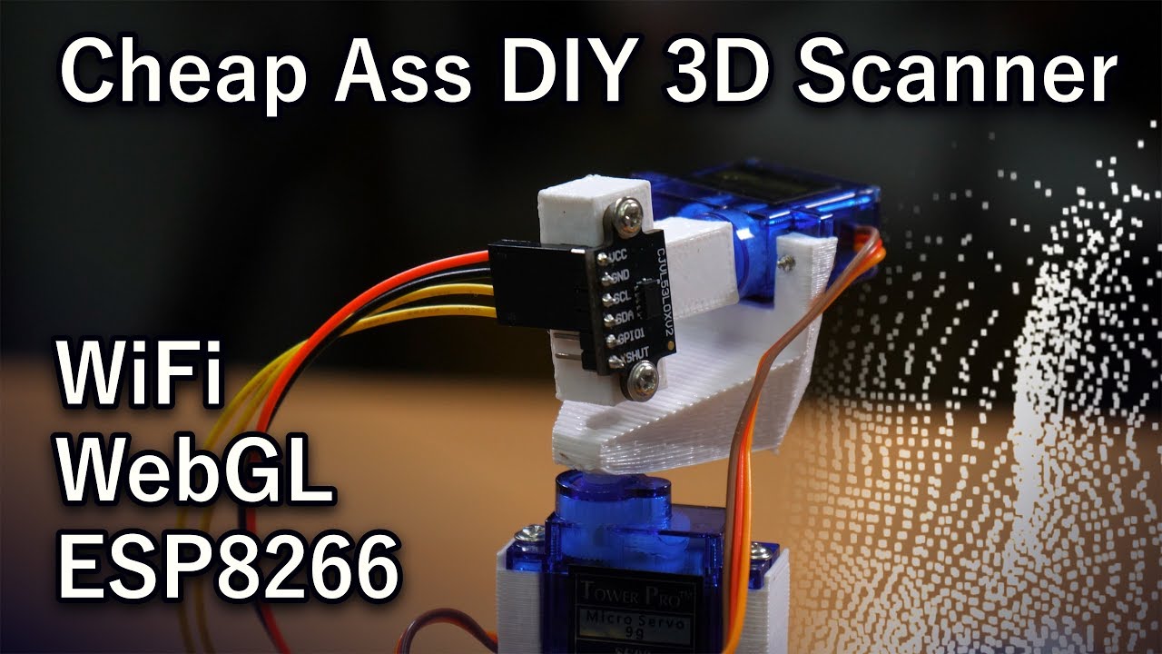
This mini project shows an attempt to built a cheap areal 3D scanner. The two attempts use an ultrasonic transducer and a time-of-flight sensor.
Part 2:
https://youtu.be/mRR7VgC_DWg
Code and 3d pritner models:
https://github.com/bitluni/3DScannerESP8266
Project page:
http://bitluni.net/3d-scanner/
Links to the cheep parts including shipping ...
Ah that sucks. Yeah most of the time the datasheets will just tell you. Think I remember 25 degrees being a typical nunber.
Though I still think the notion of using ToF with a light guide to control the fov is an interesting one
Would require an experiment to see how the change in transmission media impacts the readings, and whether they still work at all
The ST v53 family can be automatically calibrated to account for glass covers
They don't specify if this includes external optics
My understanding so far of the side-lighting fibre proposal is that the magnitude of intensity of light coming out one end is being used as an indication of how far along the fibre the light had to pass through after it first entered the fibre through the side at the point where a finger is touching it. But for this to be more reliable I believe one really needs to measure how much light is emerging from both ends.
However, they do provide documentation for how to align optics
Oh that doesn't seem like it'll work. At least as an initial reaction.
Harder press and shorter distance both produce brighter light.
Need a way to isolate them
That's why born suggested two ended and use ratio
Harder press increases brightness for both ends. Distance increases brightness for one end.
If you can strobe the 6 lasers then you can get away with them all sharing the same set of 22 sensors. This is the same trick that laser harps use. Only one "string" is lit at any given instant (it's really a fixed laser turned on and off rapidly while reflected by a spinning mirror) and one sensor detects the hand interrupting it.
And placing 22 X 6 = 132 photodiodes on a PCB ain't that bad. Just look at Sean Hodgins who hand placed over 1000 for his DIY camera sensor
https://youtu.be/PaXweP73NT4

It actually works! Finally got around to building my own digital camera from scratch. Its not an easy project, but if you want to recreate it, there are resources below!
Support my Free Open Source Projects by becoming joining the Patreon! - https://bit.ly/seanpatreon
The 8-Bit Guy Gameboy Camera Video - https://youtu.be/jenAYYTstb4
GitHub:...
Yeesh the conversation up there is rough
I need to check what Mattias actually presented to styro
132 would be a pretty intensive multiplexing challenge but certainly can be done
Assuming you're just doing on/ off on each sensor
And not trying to read analog voltage to estimate press pressure or anything
That's also possible but now getting expensive
Something to note
Just because it's possible for a hobbyist to do doesn't mean it's good for Mattias.
Mattias isn't.... How do I say this....very experienced with custom electronic PCB assembly or coding
He can do the basics, but he doesn't have the background to troubleshoot issues without guidance if something is wrong with the circuitry or the program
He basically sends us videos and photos of his builds and we talk him through things to test
That's why he has someone doing that work for him
But still good to keep in mind the complexity of the solution for the professional he has helping (in his free time)
What might be a reasonable and robust solution for a product development might still be a little much for Goran (was that his name?) To sort out on evenings and weekends
funny, the whitepapers all describe their internal RC timers that they use to measure the time delays that are too short to accurately measure with a digital circuit (so they use analog)
needs to be a pretty consistent value with that approach, and bornach's suggestion of using 12 ldrs is actually a good idea.
Doesn't have to be expensive for the feasibility testing. I just tried breadboarding a photodiode with a laser (red module from a cheap laser line level tool) shining across it a few mm above. I'm actually using a reversed biased IR LED since that was easier to reach. A couple of bipolar transistors in Darlington pair configuration to amplify the signal and I can get a change in voltage measurable by a multimeter, and that's with the workbench lights on. Complexity is the issue though if you plan on having a long row of these
Yeah I was specifically referring to the cost of having 100+ channels of ADC, or analog multiplexing, both of which can be expensive
I only had on/off in mind when I suggested just looking for changes in the value
from:1 mattis is dropping like 5 grand on his most expesnive strings video
that makes sense
i also proposed a custom pcb fret board with thousands of sensors into a multiplex IO i think its feesible
I also offered to use the PNP / reflow ovens i have access to so its not a 15 hour hand place job
👈 Look who's jealous! 🤣
So, what you do is have lasers in the head and reflect them onto a rotating mirror. This rotating mirror sweeps the lasers across the fret-board. Then you have the rotating mirror in little box with a window cut out to liniment how far the laser sweeps out. Then you use fiber optic filament, like see in fair lights, to collect and redirect the laser light into cells or a box that has a light resistor inside to measure the laser lights. Then you can pulse the laser or use a gradient that goes from black to clear on top of the fret board. This will change relative brightness. So, you can use the relative brightness to finger out where the finger is along the cell or block . Then for the strumming you have separate set of laser in the bridge. These lasers go into a half translucent mirror that reflects them down into the guitar where have light resistor to tell if their blocked or not.

but the fair fiber optics work jist as well without the spinning laser caster...no?
(the brightness of the laser light coming out at both ends of the fretboard will have a direct ratio to the distance down the fret where the laser couples into the optical fiber from a finger)
Maybe, then you would be relying on reflecting the light off the finger into the cell/box. Introduces more interferes. The idea is that the fair fiber creates a light corridor that aligns with the steepness of laser at the point on fret-board. Also, have black coating added to outside. This is all to isolate light box\cell from other laser or other points. Also the fair fiber bends at the bottom so that it fits better into the neck.
not reflecting...laser light diffracts &/or fluoresces inside flesh 😉
and we call that "Side-fire" or "side-glow" fiber optics, just FYI, the angle the light strikes it from the outside makes no difference at all, because the outer surface of the fiber is designed to diffuse the light (redirect it in many directions)
The Maybe you could get a way with slapping clear to black gradient on top. Pulse the laser to isolate it from other lights sources. Not have to even bother with laser distance measures. Just do it all with light resistors.
You could even pulse the lasers on separately. To isolate them from one another.
the fiber design doesn't have problems with isolation?
you will only couple enough light into the fiber optic to get above the minimum trigger intensity if you physically touch the fiber optic and the laser is shooting at the same finger
oh you mean if the same finger is touching multiple strings
gotcha
also use photodiodes instead of photoresistors. I have heard that LDRs/photoresistors sometimes respond slowly.
or maybe phototransistors
iirc, most/all BJTs are HIGHLY light sensistive, so an RF BJT with an exposed die would make a super-fast photodetector 😉
i did a quick google to see if there were any caveats with phototransistors vs photodiodes and apparently the main one is that photodiodes are a bit more linear than phototransistors
actually wait I'm dumb
if you're touching multiple strings then that is intended behaviour
not dumb....maybe distracted ... I mean, name someone who'se been helping here for more than 2 weeks who hasn't done as badly at LEAST once 😂
I’m just curious how you’d play something like this

I feel like fretting normally would count as breaking the beam for over 0.15 sec
Maybe pressure sensors built into the fretboard?
Then you can distinguish fretting from muting.
Pressure + Broken for 0.15s = fretting
Broken for 0.15s = muting
I was talking about the strumming area for muting, because touching a string in the strumming area for over 0.15s is definitely going to stop it from making noise
I guess?
I feel like that’d make a lot of chords very awkward
strum a guitar, then touch a string in the strumming area....it'll mute FAST
IIRC if a chord requires muting it’s a million times easier to incorporate that into the fingering
Ignore the fretboard area, those are separate lasers
Why would you ignore the fretboard area to finger a chord
what?
That’s like 100% related here lol
ok, well, I didn't even know muted chords was a thing
I'm not a guitarist
I'm just an engineer, and can't design for situations I have no way to know to expect 🤣

This is primarily why I had that idea
Since whether or not a string is muted is dictated by whether or not you’ve applied pressure to the string
In the context of lasers it’s not like you can rest your finger on the string
If you only want the lasers as input I suppose you’d mute by maybe only partly covering the laser??? it’d be really difficult to have that precision though.
Yeah fair
Will sliding be easier on laser guitar….??????
so far, MOST designs we're seriously considering should handle sliding very well & fluidly
so yes, unless you use 5W lasers, you'll be able to slide easily & NOT rip the callouses off your fingers (I'd call that easier) 🤣
(5W lasers might make you bleed by drilling through your fingers, tho )
Lmao
you wont be jealous when they have to be torn apart and fixed 😛
to be fair the potential of covering every possible playing technique might not be feeasible with any design. The laser guitar is going to be its own "class" of instrument, so i would say expecting a different playing experince is acceptable
also not to po poo anyones designs but all of mattis's projects have to be heavily DFM, like yeah it would be really cool to have a spining mirror and index the string with an encoder and measure the constructive/deconstrutie interferance of the laser
but uhhh mattis is building this into a wooden guitar, which does not have dimension stability over temperature/humidity. Also he has limited access to precision tooling. So the chances of him being able to affix mirrors in such a manner to align all the lasers is rather impossible
so when brain storming a design think heavily about DFM
In general, my mind keeps returning to fiber optics to return a light to a sensor array in the body. It'd be the easiest to work with and probably the simplest to control.
that takes us back to a pretty complex build though...with LOTS of fibers to align, and pretty poor resolution fkr the fretting, no?
Depends on the size of fiber. Stuff I used to work with was about 1/8" diameter and had a protective sleeve; it took a few minutes to align, but only because you had to crawl inside the machine to check.
Plus, we don't need to necessarily make a 90° bend
Basically use a small camera for each string. Each optical cable would have a port that can be observed for a specific color.

Amusingly, HD Audio cables would probably be perfect for this task.

i like this too but for ease of assembly i think the custom pcb with SMT sensors is probably more robust
looks scary to me...that's a LOT of fibers to align, bundle together, then spatially resolve in output array
Yeah, with 25 frets that results in 150 individual optic fibers to install. Scary, but would look absolutely majestic (in my mind).
Like something out of sci-fi
More because of positions in between frets
In situations where actual light level measurements are needed, I prefer phototransistors. And they're plenty fast for this application.
Mostly because the measurement circuits can be simpler and you can often get away without an amplification stage.
Just phototransistor, sampling resistor, straight into the adc.
Still, how cool would it be to keep it all analog? Would help it feel more organic to have "infinite" sub frets across all the frets.
that's what our top 3 hopeful designs do (side-glow optics with differential analog signals from phototransistors at either end of each optic fiber; cameras imaging the underside of the fretboard; laser TOF measurements of all fretting positions)
Did someone find an analog TOF sensor? I was struggling to find anything that wasn't I2C!
I doubt they exist. If you're buying an IC (meaning you aren't building yhe ToF sensor yourself out of emitter/receiver/timing circuit) then you're going to be dealing with digital communications
I2c or spi or whatever
An analog output doesn't really make sense in the context of a mass-produced device
Yeah I figured most people wouldn't care to take on the annoyance of noise when integrating to a project and just want a clean digital reading.
TOF sensors use an internal analog RC timing circuit to measure the delay, because we can't currently make digital counters that run fast enough (at least not at mass-market scale/pricing)
Would a photodiode and a phototransistor be somewhat interchangeable for this task?
phototransistor is basically 2 photodiodes wired into a decently high-speed light-activated BJT, so it can effectively work as its own amplifier too
so basically, a phototransistor can do a photodiode's task, but a single photodiode can't do many of the tasks a phototransistor is capable of.
Both could work but they have different support circuitry requirements, so not exactly "interchangeable"

I like fiber optic lamps but their brightness always disappoints me. They are too dim to really impress me. No matter if it is an old halogen or new LED type.
Time to upgrade my two fiber lamps! Make them brighter - much brighter. Will I succeed or is there a limit I overlooked?
LaserCube 7.5W Ultra donated earlier by https://www.wickedlasers.c...
I haven't watched this yet.... but it seems like strangely relevant upload timing lol
I'm sure someone's said this already, but maybe have the picking area function like a regular guitar, and have a hex pickup that processes each string individually. Then have the laser portion act like a MIDI controller for their respective strings, shifting the pitch to reflect the "fret" being pressed on that string
Would take a lot of coding
took a while trying to figure out what you mean
so you mean like
- have six physical short guitar strings on the body, where you pick/strum
- standard electric guitar pickups for these short strings
- pitch shift the analog output of the strings instead of making the guitar a standard MIDI guitar that depends on soundfonts
Or have a MIDI setup that just activates each string's output based on whether or not the hex pickup is recieving signal from the string's vibrations
Basically just using the strings like an on/off
Ah
But wouldn't it be even easier to just use lasers directly for that? That's the current plan.
Since the sensors directly output digital on/off signals rather than having to analyze the string vibrations and calculate whether the RMS volume was above a threshold
I guess there's the benefit of actually picking strings, that'd probably be good for playability
at that point, just put momentary-on pull-switches on the physical strings. Get cleaner strumming signals that way & requires far less complexity.
It's more the tactile feel of it, as well as the fact that you'd likely need two sets of lasers anyway, a set for pitch and a set for picking
yes, and we've already discussed and designed for both sets of lasers...at length in this channel
...using strings in place of the lasers would only defeat the entire basic intent of the project.
You also can't mute lasers, which greatly impacts playbility
the ENTIRE POINT is that it's a laser guitar!!!
We also talked about this too
Primarily the reason we are sacrificing some playability is about how much non-laser systems we are allowed to get away with before it's considered cheating the challenge
hmm telecentric lenses of the right sizes seem to almost all be made-to-order or "quote only" without set prices
yes, and the hilarious part is: there's really nothing that makes them any more difficult to manufacture! A few YT peeps have even made functional telecentric lenses using cardboard tubes & page-magnifiers!
(bot to mention that ALL M43/MFT lenses, to be "official", are required to be "back-side telecentric"
i think for our applications we may need bi-telecentric
I say "need" but it's not an important feature
yeah, I think front-side telecentric should be fine here...we don't need to be changing focal distance once it's working.
(back-side telecentricity is only useful for avoiding the unintentional "zooming" effect that occurs when changing focus on lenses without that telecentric feature.)
don't we need ultrawide depth of field?
are these telecentric lenses for the time of flight idea?
no it's for velocity sensing, which is an optional bonus
ah, having a camera detect how fast the finger pushes through a laser?
as the finger moves through the laser beam while strumming/picking/muting, the speckle pattern generated by the reflection of the laser from the finger will shift with the movement, which can be picked up using optical flow
I see
If the lasers used for strumming were a bit "thick" you could estimate speed by how fast the light level falls off
the algorithm doesn't depend on brightness, it exploits the fact that the surface of a finger is not perfectly smooth, so the coherent laser that reflects off it will interfere with itself and produce a very clear pattern of dots that can be easily filtered with a colour filter on the lens
like a mouse, right? I was suggesting using brightness as an alternative.
ahh
tight aperture & front-side.telecentricity both increase your effective depth of field...and it's not exactly plausible to re-focus during use.
I found one that had a liquid lens or electronic lens of some sort
It claimed 20ms refocus time
I don't care if it's a 20ns refocus time, how are we going to DRIVE the refocussing & how to we guess at a new focal distance BEFORE there's something there to focus on???
I think we can focus sufficiently with a telecentric lens & f/8 or tighter aperture to have no reason to try refocusing in real-time anywise
Just use 6 laser tripwires that prompt a Time-of-Flight Measurement (Triangulation Method) calibrated to the length of your guitar’s neck.
Set each time-of-flight as an individual midi input a digital guitar would have for each fret, and special fingering techniques wouldn’t work, but a basic open string concept would be to set the distance from near the guitar’s “soundhole” as the open strum for each string, and a fretted strum for the lazers that are already reading a fret input. Because the strum is a priority, the measuring system would have to be near the bridge and not the headstock.
As for the visual display of the guitar, making it as clear as glass to show that there is no hiding hardware in the neck would be very nice. A solid glass fretless fretboard with laser strings? A total slay.
(Im not an engineer though, so I apologize)
then you can't change the fretting on a string while it's still sounding though (like the bottleneck pitchbending Mattias did with the metal pipe in the 360guitar video)
So make it so that if it still recognizes a disturbance in the laser tripwire, make the measurer consistently refresh an updated status of the midi input? Because then it will read the update as something like a slide, or a hammer, and so on..
congratulations, you've now submitted one of the top 3 most ridiculously overcomplicated design ideas yet.
& btw, do some research on laser TOF units that are capable of working at these short distances....there are LOADS of drawbacks to attempting to slot 6 of them into a guitar neck
In a few more years, the laser guitar might get a bit easier when PCSEL based ToF chips come to market
Since they have a significantly narrower beam pattern that would allow them to be packed closer together without interfering with each other
try using infared lazers to when a finger touches the lazer or pick it will detect that and play it on a special software
well, only missed 100% of the important concepts there....new record!
It's a shitpost account
ban time?
You could use the same technology used in garages to make sure nothing is obstructing the door closing
Edit: sorry if this was already suggested, I just got on this discord
Thank you....it has been many months since the last new join cared enough to read the backlog & then correct themselves.
That shows a degree of responsibility & self-restraint that the vast majority absolutely lack.
Is there a way to determine the brightness of a laser? I liked the idea of using some kind of glove on the left hand to get where it is on the frets. It might be possible to have one laser on each side and use the strength of the laser on each side calculate distance. Of course, that would be extremely difficult because the fingers are not in a fixed angle and I’m not sure if calculating distance by laser strength is even possible.
(Edit: I’m not in engineering so I am not very familiar with terminology used)
Lasers' power doesn't change much with distance in air, but there were proposals made to use either timing (like a laser ranfefinder), or the strenfth of light from the laser that got dispersed by a finger into a type of fiber-optic that has an easy-to-measure loss per distance that the light has travelled in it.
Both options have advantages & weaknesses vs. each other...not sure which would be better in the end.
Is using something other than lasers for input allowed? Or does it just make things not a lazer guitar anymore
Could you flash the lasers at a speed where the human mind doesn’t know that it’s flickering so that way you could calculate the time to each side from a finger?
Edit: oops I just missed context mb
this is one of the proposed ideas...but as Mattias is wanting the lasers to be visible, it can be quite difficult to coordinate the laser strobing with the video camera's shutter in order to avoid the "flickering effect" that you can see if you look at the headlights in any of Murphy's Diesel's videos
Having to make things work on video adds a lot of complexity to many things, just because video cameras see things in very different ways from human eyes.
True, I hadn’t thought of that
np, was an intelligent idea & in definitely good taste, so I figured explaining the technical challenges was the best response.
Thanks for helping me understand
wonder if it works with continuous-wave phase measurement
no flicker if there's no pulse
How would CW phase-measurement discriminate between something 1.5 wavelengths away & something 382.5wavelengths away? (not unreasonable when waves are measured in nm)
There appear to be existing rangefinders that can... They seem to modulate an RF tone on the laser