#Regular surface distortion pattern towards end of larger first layers VC4
1 messages · Page 2 of 1
That's awesome, appreciate that, makes it easier for me to catch up too
There's definitely something going on.
Thanks! And we are being skeptical too: #1293322335545196655 message
we should make a guide out of this and pin it somewhere.. We need a #science channel 😂


So I think I got it
After cool down for the whole night then do a pre heat for 30 min and then start the print
Well, we made it to 1000 posts here 🙂

The thing that I did was to loosen the screws and tighten only with 0,8nm (in hot Condition)
The difference in surface sheen is still really strange to me.
Yes you are right but now it is usable
(Another information, I do a beacon contact mesh instead of a beacon scan)
yet you're using a TI tube where thermal expansion shouldn't even be a problem to begin with. Fun 😄
Yes but I think it is
physics is a problem again.. 😂
Because before I loosen the screws and … I don’t get a good surface not even a usable
Yes 😂
It's worth noting that z-offset inconsistency problems are often related to premature modding, especially swapping the 2020 for different tubes with less rigidity. I would assume the TI tube is rigid enough, but since it's not an official part it's one of the things i would take out of the equation to make any sort of conclusion on this one.
@gloomy kernel what is you opinion about printing up down up down vs 45 angle? Does printer have to do less work to correct errors when printing up and down? For me first layer quality is way better printed that way. When printing something like 400x400 0.3 sheet
Titan should be more stiff then Alu
I primarily print with 0 and 90 degree infill direction and rotate my parts 45 degrees on the plate so that "align seams at rear" ends up on the corners of parts. It should not make any difference as far as first layer goes, everything in the mesh is interpolated anyway.
But I also have to say that I pushed my titanium rod up at the beginning with the bed (0.2mm) and then tightened the rail with 2.2nm so I already had a certain tension in the whole thing and then it probably warped due to the heat
Now after I do the steps I told you I can see on the mesh that the gantry is a little bit bowing but not from the heat the ti tube is a little bowing but that can the beacon compensate (because it is a stable bowing)
Okey.
I’ve played with the gantry heat soaking by sweeping the hot end across the gantry. It does get rid of the long-term effects, but there are still short-term changes in the first few minutes of printing. Part of that might be due to the fact that I switched back to using contact true_zero, in order to avoid needing to calculate/derive myself the offset I need to add. And contact probing is done at 150, so I drop there for a while, which might cool the gantry down. Or then it could be that sweeping is no more effective than just staying in one place. In short, pre-heating the gantry is not trivial.
@dusty rover are you running with 16 microsteps on z as per #ratos-development message ?
No, but I’ve done a pretty thorough drift test, and that showed no signs. But yes, I guess there is very little harm in switching to 16, perhaps some loss in z resolution.
Where I can find mine?
But I also have to say that I pushed my titanium rod up at the beginning with the bed (0.2mm) and then tightened the rail with 2.2nm so I already had a certain tension in the whole thing and then it probably warped due to the heat
... why would you do that?
Oh it was to compensate for a out of the box bend in the tube?
Because the tube makes a bow
And to get off from this I bend it in the other direction and thighten the screws
Gotcha. Yeah that'll definitely do weird things when heated.
Yes
internal stress is the root of all evil.
Now I think I will compensate with capton band
much better fix 👍
Yes I learned so 😂
Or accept that the bed is flatter than the gantry, and turn off mesh fade?
Yes
That's an option too yeah, but when shimming you can achieve actual flatness which is definitely preferable.
But if I want to use the Idex in copy mode Than both should be straight
Is kapton thin enough for accurate shimming?
Because if not then one side have a good first layer and the other not
eg #1291319216594747432 message
Yes I think so I have one here can measure later and tell you how thick it is
I don't know actually. Never done it myself but i know a lot of users have had great success in shimming rails and beds with kapton.
as in <0.05mm flatness across a 500.
it's a lot of meticulous work though
I’ve used alu folio in some cases.
Yes that is right
But hey if you want it perfect you have to work for it 😂
How are people actualy measuring that? Putting a rigid true flat straight edge on the bed and using DTI to the nozzle? Surely you can't rely on bed meshing to establish if the gantry alone is flat (as installed, as opposed to on the bench) because you can't separate bed and gantry innacuracies.
What's that?

KS Tools 300.0638 Präzisions-Haarlineal, 500mm
This one
Whre do add that? I know nothing about coding
Copy it to your printer.cfg
ok, so you put that on the bed and then check with feeler to the nozzle which you set just above the edge? Or what is your measuring setup?
I put it on the gantry
And put a light behind
And if I see a light the it is not straught
And there where I can see a light I put a capton band
And then I know the gantry is straight
Like this?

What is the gap between? The straight edge and what?
And the tube
Can you take a photo of your measuring setup?
Yes if I do it I will make a picture
Did u mean the rail?
Where do you put tape then?
On the tube and after measuring the rail come on the tube
And also on the laptop
Karton
Kapton
Yes
you're of course correct. All people care about is the bed mesh, that's all they measure.
But you want the rail to be straight, right? I do not think it matters what shape the tube is
Yes in the end I want a straight rail
But if the tube is bow and you thighten the screws of the rail then the rail gets bow down to the tube
@untold berry How good does your fitted pei sheet look compared to your straight edge?
There is no guarantee that the rail is straight. You need to measure the combined structure
You can’t see there anything because the problem is the roughness of the pei so you can’t work there really well with the light
Btw what extrusion multiplier you guys use?
Yes of course but at first I have to make the ground straight
This is for every filament different
You I know forgot to specify to pla. I assume they are not that far apart
How does that relate to the issue here?
I have tried everything from 0.9 to 0.97 and sometimes quality changes and sometimes dont with same print back to back printing. Just wondering why is that
You need to follow one of the methodical approaches to calibrate this. Watch some teaching tech you tube videos, search his channel for "flow rate".
Values below 0.9 are not uncommon on RR because we don't do esteps calibration (for good reasons).
@surreal lantern , did u ever measure the gantry bow again with the reverse fan, after the PID?
I’ve been trying to figure what could cause the difference, and only come with the fan being somehow very good in my setup..
No, or maybe. But regardless, I'd like to redo this for both fan directions. We should agree on a DTI test setup and temps etc and both redo the test. I also want to switch to 16 microsteps.
16 microsteps it is then 🙂
I've also got the last print from yesterday to report. It was a complete spiral. There's an interesting sudden artefact near the end, which I've seen before. I'm wondering if it's a (thermal?) stress settling thing as the toolhead starts to cover nearly the full (z correction) x range near the outside of the spiral.
I think we need to measure how tight the screws need to be to show the bimetal effect. That will be a bit challenging, as it is not only the tightness, but also any possible dust/grease/whatever one might have between the rail and tube.
If we are near those limits, then sudden changes would be expected
One goal is reliable reproduction of the issue, for which any rail/gantry friction that's reasonably far above any slipping threshold will do. Then there's the goal of understanding causes of effects. And then there's the goal of fixes and workarounds (full or partial).
Correction - reliable reproduction that demonstrates any kind of bowing from hotend thermal effects can use any rail/gantry friction above and clear of a slipping theshold. But reprodcution of thermal "judder" could well be related to some specific friction threshold.
I'd like to develop reliable procedure that demonstrates the basic concept of bowing from hotend thermal effects. As per eg #1293322335545196655 message, this seems to be the first step to general acceptance that the issue exists. If others can reproduce it reliably, that would be good from a methodological perspective.
I can think of two broad categories of procedure: by measurement (eg involving a DTI setup) and by evidence from a print.
As regards separating expansion effects from bimetallic effects, perhaps a test with full losening of the rail would allow the pure expansion component to be identified?
Yes, it would. Btw, I’ve done it’s, and it works as expected.
And going a bit further, we might also want to examine y axis bowing given that the gantry is heated unevenly from the front only.
Has anyone else reproduced this? I can try too. But I'd like us to write down the test procedure and then I follow it to the letter as this will be the basis for wider reproduction.
Yes, and indeed my initial measurement of that showed just the slightest twist, but I did not follow it up. Might have been an error as well. One thing to measure, yes
The way I measure is:
head at middle of bed, z such that the ganty is 50.5 mm from bed (to accomodate the use of my toolsetter). DTI attached to the bed, with probe touching the middle of the rail, abt 50mm away from the gantry center. I measure the temp of the gantry with a thermocouple, using the clip I showed earlier. Measurement start/stop should have the extrusion temperature within 0.2C of ambient.
What is expected btw? As far as I can tell, there's no designed-in accommodation for gantry expansion along the x axis (the gantry getting longer), so I'm not sure what would happen.
Ah, ok, did not measure the length. I just meant that there is no significant bowing with the screws loose
Yes I think this is a point
What happens with just the extrusion’s independent expansion might depend on how the close the y-rails are, and how soft the xy joiners are etc.
What we really need is some magic noexpandenisum that can match aluminium or titanium for weight/stiffness/etc, but with magically negligible expansion. Then life would be much easier.
I might rather take something that has the same expansion as steel 🙂
Carbon fiber has lower coefficient than steel if I am not mistaken. Perhaps we could add a strip of that at the underside of extrusion? And, yes, I am at least half-serious.. 🙂
CF has a negative expansion coefficient IIRC.
Then it should work fine for us. We just need the correct amount of it
I have to head out, will get back to this in a couple of hours or so.
#6 turned out somewhat decent. This is with a print time of 35 minutes. There is some drift and squish visible at 11, but it might be fixable with slightly increasing the z-offset, by increasing the coefficient multiplier. My multiplier is now a pretty humorous 3.3. This is a result of measuring the real hotend expansion with a reversed fan, so the gantry bow did not come into play there.
The probing method is now contact. The code is now updated at [email protected]:matti125/gantrywarmer.git if someone wants to give it a try.


Ah so now with gantry warmer code and reversed fan + new hotend expansion ?
No reversal here, this is with stock direction but a new hotend expansion. If I reverse the fan I do not need any compensation, the 30second heatsoak is all that is needed.
My real hotend expansion is abt 69um/100C
Ah yes I meant so
This measures the beacon while the beacon calibration or ?
This is with the RatOS BEACON_CALIBRATE_NOZZLE_TEMP_OFFSET
..and a reversed fan
#7 came out better. No immediately obvious squishing, and no see-through slots. The difference to #6 is increase of soak time from 10 to 20mins. This is with 0.25 layer, as was #6. And they are printed from outside to in, my slicer just happened to do it that way, and I forgot to change it.


I'm having a look at the hotend design. The 2020 has (per CAD) 1mm clearance to the rear, 3.65mm to the front, 1mm below. Any kind of deflector shield to stop hot air from hitting the front of the 2020 would likely need to have 1mm clearance to the 2020, and be at least 1mm thick (2 perimeters), leaving only 1.65mm of the original 3.65mm clearance. This would probably constrain the exhaust airflow noticeably.
However, one thing I notice, as the screenshots try to reveal, is that air can flow over the top of the heatblock and the PTFE sock (which gets properly hot too), with the exhaust air likely hitting the lower front edge of the 2020 and wrapping around the underside of the 2020. If anyone has a thermal camera, it would be great to see if the underside and lower front face of the 2020 is a hotspot. Changing the design of the "toolhead front" printed part so that the airflow is kept to the heatsink might reduce heat transfer to the 2020 and improve hotend performance by not cooling to top of the heatblock and sock.


I can get a thermal camera tomorrow
Great, let us have a look at that. Your situation will be a bit different, as there is no profile groove in the Ti tube, but still very interesting.
#24. The last back-to-back from yesterday. Cold bed pla, 0.4 noz, 0.3 layer. 2-6 appears mostly perfect for the whole print. 6-2 is slightly scuffed increasing to roughness 8-12. This scuffing/roughness is present from around 50mm dia to the end of the print, slowly increasing over time. The worst roughness, at the outer edge centred around 10.30 is still on the milder side, a light wave pattern, not ridging.
A notable feature occurs 35mm from the outer edge. It's not clear to me what exactly happened. But the print split along that line as I removed it. The split runs from about 7.30-2, but there is a continuing visual artefact at that diameter subtly visible for the whole 360 degrees. I've tried to work out if it's a sudden thinning or thickening, but I can't be certain.
Similar arcing features can be seen on #7, and seem to occur near the end of the print on full spirals only.


Yes will send photos tomorrow
Another question
How do you make the light on the nozzle ?
I was already looking at the cheap thermal cameras, but decent ones are not exactly cheap 🙂
Yes I have one from my business
My nozzle? My mod here: https://www.printables.com/model/956804-headlamps-nozzle-lighting-for-ratrig-v-core-4-tool

Printables.com
Adds extensions to the part fan duct with RGB LEDs that perfectly illuminate the nozzle and print area without shadows. | Download free 3D printable STL models
Ah nice thank you


Here you see in the mittle a gap
This is with capton

And it is way better (0,1mm better) but I have a little bit too much on it
Will do it tomorrow again
And the caption is 0,05mm thick
#8 is 390x390. It does not show temporal issues, but instead at around 10 and then almost the whole back edge is ever so slightly undulated. It is almost like the beacon is getting it slightly wrong so close to the edge. I do not have scan compensation on.
The lines are solidly merged together, and it feels my z overall might be slightly too low. But overall, I am positively surprised at how good the full bed turned out to be.


Stock fan direction, 20mins gantry, 5 min hotend heatsoak, .3mm layer, 50mm/s, start from direction 7:30, time to print abt 2h.
Sorry @untold berry , did not mean to answer to your post, this is not related 🙂
Stationary gantry heat soak by hotend only test. Machine idle for hours before, bed off, enclosure front not present. I attached a pair of thermistors, one near the lower edge of the front of the 2020, the other near the top. I'm seeing about 3 to 3.5C higher temp on the bottom sensor right from the start, so initially likely air temp reading. After some time it will also pick up gantry temp. Currently 25.7 top, 29.3 bottom after about 3 mins. Ambient before test was 20C (+-0.2 depending on which termistor you read including the ambient ones on the printer).


Pretty hight temperatures. Wha is the hotend temp?
I get like 8 degrees with 250 if my memory serves. Could you try with the clip?
I need to print the clip. This is combined air and gantry temp. But usefully suggests that the air coming out lower down is hotter.
Yes, indeed
Can you share the cad? Or do an upper/lower dual thermistor version?
it's up to 115um now
If u do onshape, it is here: https://cad.onshape.com/documents/5fb95f99586bf3c48821def6/v/1fae21088d08688b9d852f4b/e/50ddd7b68080f5e2099b216b
Sign in to Onshape, the #1 fastest growing CAD system in the world with over 4 million users.
Note that I'm seeing 6.9 above ambient on the top edge, 10.3 bottom edge.
Ok, then it is in line.
The two-sensor version could be two mirrored clips?
Although I do not know whether it really makes a difference. I was just mis-reading the result.
Made it to 150um
You have the filament in place? I was just thinking whether you can crank it to 250 at some point after it stabilizes.
Filament is loaded, but i could unload it
just signing up with oncad so I can see your design...
Do you think your clip will shield the 2020 from hot air?
I hope it would shield the sensor, yes
displacement still increasing, now 165um
But it might also shield the 2020, reducing its temp increase.
But anyhow - looks like I'm getting comparable values with my masking tape.
I wonder why this happens in the graph? The recent "quiet" bit. Could be a graphing artefact or actual measured data.

It would, but the area it covers is not extremely large. My gut feeling would be that the effect could be ignored.
That is most probebly a Mainsail issue. Does a refresh help?
Cheked my notes, and in one case the reading increased by 10u even after 1h15mins. This is a long process..
Of course we are at the limits of my measurement device resolution, so noise could contribute as well
yeah, it's still crawling up, temp and deflection, but like 0.1 C per several mins or so now.
And... sorry, there was another change in the setup at that time. Forget about that datapoint.
I need my logging DTI 🙂
Or several logging DTIs and temp probes. A lab, in fact.
ditto, will wrap up now.
Kapton tape on the front of the 2020 would be a way for a quick test if some sort of shield would be worthwhile
Excellent idea! I’ll try taping the whole front of the gantry tomorrow.
Sorry but how much bowing is the gantry now with the test ? (Only the hotend)
Nice idea
And what is this clamp for ?
Ahh was this the end ?
It’s really much for a thing that nobody watches at
Not the end. Hang on...
Start and end. It was still creeping up very very slowly. 0um at the start, 175um at the end.


Temp was ~20.0C to start. At end 28.1C upper front face of 2020, 31.6C lower front face of 2020.

It is for making sure the temperature is measured at the same place on the extrusion, with the same contact pressure, and so that we measure the aluminum temperature, not the air temperature.
I get 8C with hotend at 250, but that is measured at the backside. Perhaps it would be worth trying with the clip as well so we can compare the results? Or perhaps I should shorten the clip first so that it doesn’t cover the extrusion groove?
#beacon-contact message
Suggest you hold off on taping your whole gantry unless you've got kapton tape to burn (it's not cheap) as it will make comparative testing with eg me impossible. I have something in mind that I will need you to test too, hopefully ready by lunchtime Monday UK time.
I’ll hold 🙂
What timezone are you btw?
UK, currently Z+1.
Me in Finland
Ah, nice, jätte bra. I have connections to Sweden but have never been to Finland, but I want to. I must go back to sleep, I was dreaming vc4 thermals fixes and just wanted to avoid kapton wastage!
Ok, vi kan tala svenska också 🙂


Starting from a cold machine, could you try just heating the hot end at 215 or 250 if you don't have filament loaded. After 1 minute, move the toolhead out of the way and quickly take images of the gantry from the front and underneath? Then move the toolhead back into place and carry on. Take images like this again after 5 mins and 10 mins.
Make sure the toolhead is not in the image so that you can see the subtle variation in the temperature of the gantry itself. The expected temp range will be 20-40C.
Yes I can do this after the print (in 1-2 hours)
@dusty rover I've come up with this add-in diverter to keep air off the heatblock. Just doing a test print and fit. Fusion really does not like working with organic surfaces, even if they originated in fusion. I've had to start from scratch a couple of times when one approach (eg, thickening surfaces) refused to work at the end of the workflow. Grrr. So it's a bit rough, but hopefully a viable PoC. The idea is to take the fan off, insert this, reattach fan, no other hotend rebuilding needed. If this works well, it would of course be far better to design this into the actual toolhead front part. Will share once fit test is ok.


Looking good. It would seem like this should be a great addition to the fan reversal, but should improve stock direction as well.
it fitted with a slight trim. Just going to give it a quick try.
Seeing delta T between top and bottom of 2020 of ~1.5C, was ~3.5C.
Average hotend PWM ~22%, was seeing ~34% before.
Yeah, the part enclosing the heatsink is very leaky. In fact, worse, is the possibility that a reversed van could draw air past the hotend and onto the bottom of the heatsink.
Modifying the toolhead front part might give greater scope for reverse fan optimisation. I would consider steps to deter drawing hot air up from behind the heatblock with an integrated baffle of some kind, and possibly some small opening in the area of the blue line shown to create slight negative pressure and draw a small amount of hot air from the area above the heatblock, detering it from being draw round the back and over the heatsink.

Here's the hotend fan duct insert rough PoC. Print ABS 0.2 layers, tested with 0.4 nozzle. No support needed. Trim off any blobby tip from the "horns" (red circles). And gradually trim where the green line shows to help it slide into place. The CAD is a hot mess, this is just a rough PoC. Insert carefully and gently, it's fragile. And note that it slides in between the first and second heatsink fins. Line it up carefully.


Hmm.. the goal here would need to be to concentrate as much of the airflow on the cooling zone of the hotend (the heatsink) while blocking any flow to the heatblock. But I see your point of making sure air does not circle around from the back. It is a bit of a compromise between the cooling zone cooling and preventing gantry from heating.
These little excess bits were proving annoying to trim in CAD, they are too thin to print and don't turn into actual extrusion, so all is good. Just ignore them. The little overhang sorts itself out, no support needed.

The overall balance of benefit would need to be determined by FEA or experimentally. I was imagining just small bleed holes might be enough.
So it cannot be fitted below the first fin?
I think the risk of melting is high, and the benefit small.
But this is just a PoC to see if the idea has legs.
Yes. The deflector cuts one fin off and makes it susceptible to recieve radiative heat from hotend, so this does warrant some testing
Or of course it does not change the radiation, but prevents convective cooling
Eager to see how it works 🙂
Unfortunately got some work stuff that need doing as well...
If the toolhead front part was instead redesigned, it would be easier to at least expose the upper surface of the bottom heatsink fin to airflow..
The heatsink has a funky notched design. It would be easier to create a snug fit part when the part is fitted by moving it up along z. The retrofit deflector has to be fitted by sliding in along Y, so this is some compromise to avoid leaving lots of gaps.


OTOH, some gaps might fill the role of the bleed holes for the sucking fan?
I would try to avoid drawing hot air over the heatsink, so I'd use bleed holes that come closer to the fan than the heatsink.
I would be careful with reverse fan setups as these fans are not rated to handle that hot of air coming off the hot end. I suspect it will shorten their life expectancy
That's a good point, but the amount of hot air would be small and it would get mixed with ambient air.
I think I need some kind of thermistor inside the heat break or heatsink to be able to evaluate cooling performance. Any ideas? I have a couple of brand new unused rapidos.
How about potting a bead thermistor in the heat sink set screw with boron nitride paste? I use this technique for the bed edge thermistor: #v-core-4-mods message
Ok, got it installed. Had to shave off a bit on the right side, but is still fairly snug. What would you like to try?
In terms of getting to RR accepting a design change at some point, be it duct only or duct and reverse fan, we need meaningful data to compare how well the heat break is working.
A bit of overlap?

I did Boolean subtraction. But the surfaces of the RR model annoy fusion so it won't let me offset them.
So there's basically no clearance tolerance.
But this is just a poc.
I'd like to be confident that any change will not increase the risk of heat creep.
See #1293322335545196655 message
For testing right now, it might be eough to stick in a thermocouple just between the lowe fins, and us standard heatsink thermal paste. The temp should anyway be well below 100C, so boron nitdride would not be needed. My understanding is that the the silver-based pastes have lower thermal resistance, and boron nitride is useful only if you go above the rated temp for the standard pastes
Boron is great for potting as it's water soluble. Cleanup from thermal grease is a nightmare.
If (if) we are mostly concerned with steady state performance, the thermal resistance to the probe does not matter so much. The measuring point just needs to be consistent and a good proxy for evaluating heat creep risk.
The boron paste I have is a bit too slippery that I would trust it to be of help unless it is somewhat securely squeezed between surfaces. What technique did you have in mind for set screw? Do you refer to the set screw that tightens the heatbreak tube to the heatsink?
Looking at your bed thermistor your boron nitride seems to coming from a different planet 🙂
Yes, that set screw. Did you look at the link to my bed edge thermistor mod? Boron paste dries quickly. My paste is the slice engineering stuff.
I would use a blunt needle and syringe to fill the set screw hex hole then insert the bead, then gently heat to dry.
Yea, perhaps I should add some water. It just feels a little dubious to have water anywhere where you want to transfer heat
..in high temperatures..
But yea, we could try that
You just have to set the temp to 60 or so for a few minutes then all the water is gone and the paste is dry.
You have to avoid boiling the paste as steam will build up and eject the paste.
But it dries quickly in small quantities like this.
Ok, let me have a look whether I have an extra rapido to use for this
I am a few hours offline and so many messages 😁 Can you briefly update me?
An old rapido from eva3. As you can see, that seals the airflow better, there no open path to the hotend as there is with the current one. I believe I could stick a thermcouple in the hole.

Really interesting to see that this is potentially a design regression.
Yes. I initially thought that the apparent worse behavior with vc4 compared to vc3 was mostly due to going from 300 to 400 (and it probably is), but this would be on thing to compare.
But now I need to make something to pay for this.. Away for a bit.
I'm still thinking about how to measure steady state heat sink cooling efficiency. I'm wondering if it would actually be better to measure the temp at the top of the heatsink. We don't care about the absolute number, we need to know if setup A yields more or less cooling than setup B.
Also, consider this aspect of the rapido 2 design. Is seems as though the bottom 3 fins are intentionally thermally isolated from the main heatsink - there is minimal meat connecting them (red circles). This outer donut seems to be structural. Therefore I question how important it is to get airflow over all of the bottom 3 fins. Note also that these bottom 3 fins have only token recesses between them: arguably this is more of an aestetic thing. If the bottom 3 fins were in fact just a smooth cylinder (which they nearly are), would we be significantly concerned about blowing air over them?


Here's Phateus's own model of the Rapido2+ with their Voron adapter. The bottom fin is not in the airpath. The second fin is partially in the airpath. Red line shows vertical extent for clarity. I would suggest that this at least partially confirms my thinking in the preceeding post.


Good enough?


If it Has no holes I would say yes
No holes

What's this?

@mazas I'm thinking of just doing a cold pull, taking off theorbiter, and putting a thermistor down the hole, hoping it ends up against where the PTFE would normally stop.
It seems the bottom 3 fins are little more than just aesthetics. However, it would seem like that this part of the heatsink needs cooling quite a bit, since it gets the heat from through the screws. That would seem to be the reason why it is only thinly connected to the rest of the heatsink, as you pointed out.
I tried that with the thermocouple alreade 🙂
Probably little dirty bed. Right next to first layer test sheet so finger oils 🤷♂️
It seemed a bit flimsy, but we are interested in differences, so it might be good enough?
Yeah, worth a try. We just need relative values between different test setups, in steady state. the bed on mine is 1.75-1.80 dia.
Could put a layer or two of alu tape around it to be sure it gets stopped at the top end of the heatbreak.
That would be perfect. Mine is 1.2, if memory serves
I have them with JST so I can connect them direct to octopus, then I get combined graphing. Is there a way to get csv data for all the sensors etc?
And seal off the top with some bluetac or similar perhaps?
We could read them from klipper or moonraker
I mean we could stream them, but don’t know how to get them after-the-fact
If you have any know how on this, it would be welcome, I have never played with any moonraker apis, and I don't think I have the spare capacity for another learning curve. I already had to learn javascript and typescript for the post processor rewrite.
My experience is limited to reading the gcode output from moonraker, but cannot be too difficult :). Lemme have a quick look at least
If you're happy with it, then that's good. I can't really use your prints as part of the body of evidence for investigating this issue because you're not mentioning all the critical details (temps, layer heights, pre-print state etc, and I don't generally get enough detail from the photos you share to really asses the first layer quality). If you find a way that works for you with your kind of print environment and requirements, that's good news. @dusty rover and me (and maybe others sometimes) are working through the identified effects, and evaluating fixes (such as fan reversal). I think we're now at the point where we have a lot of evidence that the hotend fan contributes to gantry bowing. When we have some evaluated fixes, it would then be helpful to have others try them.
Helge said reverse is bad idea and i think he has most experiense with this printer
That's why we are carefully gathering data and evaluating changes to the hotend fan duct design.
There is an extremely simple way to get the last 20 minutes worth of data, but there is no foolproof way to make sure where the batch starts&ends. I guess we could match on the values in practice, buy that is a bit kludgey. Perhaps it would be enough to query just the current temps. But this way or that, does not seem difficult.
Anyway my print settings are. Pla, 0.6 nozzle, 0.3 layer height, 0.65 layer width, 110 speed, 500 acceleration, nozzle temp 235, bed 65, 20-30min bed heat soak, printer config z motors microsteps:16, differend print sheet, variable beacon contact z tilt adjust:true
maybe enable mqtt and use https://mqtt-explorer.com/
Mqtt, websicket, rest all should work fine. For our use perhaps a simple polling with 10 second interval over REST would be the simplest
I’ll try that tomorrow morning, now need to go
Tried the kapton. I still get a bow of 170um, down from 180, so the effect was not quite as significant as would have expected
One way to get graph immediately is
~/klipper/scripts/graphstats.py /tmp/klippy.log -o loadgraph_extruder.png -t extruder, see https://klipper.discourse.group/t/advanced-trouble-shooting-graphing-klipper/6613.
So, basically your test would show that the issue we have been trying to fix does not exist on your machine? As far as I can tell, nothing on the settings addresses the gantry bowing.
Is your printer enclosed?
No, front door removed
Okay i have only back panel for now.
Try all my settings 🤷♂️
No, I am not going to do that 
In all seriousness, we have identified a very real problem, and are now trying to find a fix for it. As you might have noticed, there are already a few methods to get a reasonable first layer: back-to-back printing, pre-heating the gantry, reversing the fan. And then there are several more ways to hide the errors, which include increasing the print speed, using larger nozzle/linewidth/layerheight. Your datapoint which says that your printer does not have a problem is valuable in that it adds a variable to the problem-solving space, namely whether there are any walls around the printer.
What speed, layerheight and width should i use to test again?
What you want me try?
The main thing is to start with cool gantry. Hopefully within 0.2C from ambient. After that everything is ok. We have been printing with 0.4 nozzle and 0.2, 0.25 and 0.3 layerheigth. Print speed of 50mm/s. Cold bed, PLA. To see whether the printer has an issue or not, I’d change the nozzle to 0.4, let it cool overnight and the do print with 0.25 layer height, 0.45 line width 50mm/s. Minimum print time of 45 mins. If it clears that, it would be a cool datapoint
What I can say now about the ti tube is that it is way better (after take out the Tension)

0,25 layer height
No holes
But still eg wave pattern a along the bottom edge of your photo.
Yes but I think because of the acc (I had 1500 on first layer)
Maybe, but the distance the pattern extends from the edge varies quite a lot, I don't see why that would be an accident/pa issue.
Because it’s everywhere on the edge here

Interesting that the shimming changed so much. AFAIUI, it means that the initial bending produced a non-uniform stress along the metals. It would have been nice to know how the static deflection changed. Did you get your DTI yet?
@teal trench , what about your cold bed measurements, what deflection do you measure?
Bte, your gantry seems rather out of square. Is this a result of the current RR instructions or https://mazas-3d.notion.site/CoreXY-Belt-and-Gantry-Tuning-with-VCore4-3-ed6eb94671d54c44a7228eb45eeb4cf9?pvs=4 or something else?
Or is the bed just out of square?
Did the print start from the top right corner of the pic? Seems there is no squish there, but rather visible in bottom left, or how would you see it?

Sorry I think it is too early but what do you mean 😁 (I am in Germany so it is 5:50 o clock in the morning)
High 0.2s. I don’t remember off the top of my head and I am out of town until Wednesday evening for work


It seems like the print edge is closer to the bed edge at the bottom. It could be because the bed is not square to the y rails, but OTOH it would seem like the distance from top of print to top of bed stays the same
Thanks! Verifies the measurements we did earlier. And debunks my first suspicion that the backing would be heated more than the rail. This is with 250 hotend?
Ah yes maybe a little bit but on the picture it looks like a bigger difference but in real it is not so much
Yes with 250 degrees
Thanks, so we have now theree different printers that exhibit sort of similar creep with cold bed. We’ll need to see what the effect is in a warm chamber. I’ll heat the bed to 60, heat soak at 2mm and see what numbers I get after turning the head on. Fortunately my DTI is a cheap&crappy one, so it does not really matter if it decides it is too hot for it 🙂
You can measure the squareness and dimensional accuracy by drawing a larger rectangle (of perhaps just 3 lines) and measuring the distance from the bed edges
Quite surprising. So it starts too low but ends up higher. Was the gantry at ambient when you started? Bed at ambient? What kind of heat soaking?
Good idea will do this
Yes
No enclosure was closed and 30 min pre heat 120 degrees bed + active heater
So 50 degrees in chamber before print
Ok, good to know, not exectly comparable to a cold bed 🙂 . Was the testing methodology the same with the non-shimmed version of the gantry? The same starting temperatures of the gantry and chamber etc?
Yes but bevor it was with 0,3mm layerheight and this was with 0,25 layer height
Ok. Anyway, the test shows drift to the opposite direction as what the gantry bend causes, which is pretty interesting.
Seems I cannot check the logger this morning. Hate that I have to work 🙂
I think active chamber heating adds another variable which complicates things - there might be effects specific to this. As per @dusty rover #1293322335545196655 message, it would be good to add just one new variable (heated bed) following on from all the cold bed testing.
My focus for now will be on measuring heat break cooling performance with stock versus modified (normal/reverse fan, duct changes etc). It would be great to find a reversed fan/duct combo that is at least as good as stock.
These are great! Because the belts block the view of the upper or lower half of the tube, could you try the same thing, but moving the head out of the way to the left, take image, then to the right, take image - minimising the time between the two images? If I'm not mistaken, all the images you shared so far were with the toolhead moved to the left, yes?
Yes all pictures was with the toolhead on the left
Yes I can do this tomorrow morning or this evening I will send the pictures if I have them

I finally finished with the heated bed measurement. With bed at 60, and hotend at 2mm, in middle of the bed, the change over 2 hours without the hotend was abt -470um. Turning on the hotend increased the deflection by -170, to -640um. After switching on the hotend, it took abt 5mins for a 100um additional deflection. It would seem like the hotend-induced deflection is not limited to cold bed only, or to open enclosures only.
That path would seem like it contains the airflow a bit better
Yes I think so too
Not sure, but it sure looks the same as the eva3
No
It is more closer
I get the stl later
Then I will send it here
Ok. Just comparing to this: #1293322335545196655 message , it looks similar

Yours seems to have something there, even though the cad model seems lacking it? Mine has that as well. Is the cad for the Minion?

Don’t know got the stl from a friend
I've been swamped with errands today, but I hope to get started with some heat break temp tests soon. I really wonder why they abandoned constrained airflow in VC4 toolhead?
Probably an oversight, as it seems the bending issue is unknown until now?
But we’d need to ask. It would be nice to get someone from RR at some point to comment and perhaps thinking about the solutions
There's both the constrained airflow and the fan direction. Only the constrained airflow is a regression.
I was thinking that, but wanted to get data on heat break temp to inform design choices.
Fair enough. And also, it would be good to get comparative results to the vc3 / eva3 hotend. The gantry of vc3 500 and vc400 are rather close, I’d think. So if we had a vc3 500, we could see how it behaves. Not exactly the same, but might be indicative
Notably any talk of reversed fan is likely to get shot down without data to back it up.
That is very true. I have not seen fans of this size that would be a bit more punchy. The one that slice engineering uses is a bit beefier, but smaller as well. Once we get a test bench set up (i.e. the thermocouple where the ptfe ends), it would be really interesting to check different fans. I would be surprised if we could not get the same effect from a better sucking fan than what we get from the current blowing fan
Switching on the extruder added another 10..15um in 50 mnutes, so it does not seem to be very significant.
So how long do you preheat ?
And the problem is (what I think) that the head is so small that not the complete gantry is warmed up
We need In any case a new „case“ for the hotend I think this is the only way or what ways do you see ?
@gloomy kernel maybe he can help or @rancid berry
By "case" I assume you mean the printed part the surrounds the heat sink. Yes, investigating changes.
Yes I mean that
I think it's a bit premature to summon those two. We need more data first.
Maybe I can test the minion
thats a lot to read, what is the qeustion?
And then we need to summarise and present all the findings and suggestions in a digestible form.
I'd hold off for now. We are still investigating. I don't have a question for you myself right now.
Why changed the „fan enclosure“ from the v3 to the v4 to the new design
That is the question I have for now
Is there a special reason
With the temperature camera
And see how the old one performed
It's kind of interesting, but it's too small as a printer to make useful comparisons re thermal bowing of the gantry. A vc3 500 wouldg be an ideal machine to compare.
However, It would be interesting to know how much the gantry gets heated above ambient by just the hot end. So yes, thermal images would be interesting.
I did not preheat, I just turned on the extruder on when the hotend was hot. And the hotend had been hot for close to two hours.
But I am not sure I get what you meant with the head being so small. It does create a local hot spot, but it would not help if the whole gantry was heated up at the same time. The metals will still have different expansions.
I knew a person how has a vc3 500 I will ask him
But what does he do exactly
Does he have a DTI? Could he measure gantry bow with just hotend? We can explain the exact setup if he has DTI.
I ask him
I guess it's good we implemented both bed and hotend heatsoak time.
@dusty rover I printed your clip modified for my bead. It's touching the lower front face of the 2020 to the right of the hotend. Where you put yours?

It's perhaps not that simple. I'll get back to you properly after I've eaten, and try to summarise unless @dusty rover beats me to it.
I still don't understand how it's possible, and especially not how the hotend adds the same amount of deflection when heatsoaked with the bed at 60 degrees. Somebody needs to ELI5 to me 😂
awesome 🙂
i even tested this on my idex with both hotends heatued up placed in cetner x, i could not measure any temp difference at both sides of the extrusion at all, measured where the bed edges are on the backside of the extrusion
The part about the RR toolhead hotend face being more open and potentially able to blow air from the heater itself makes sense, still seems a bit like a wet noodle making a dent in 10 inch steel to me. But i'm obviously wrong.
and it was only a IDEX 300
yeah that's what i would've expected, yet we've got two guys here who see up to a 10 degrees rise in temp
I need to know why
@charred plaza have a vc3 he can make some tests for us @surreal lantern or @dusty rover please explain him what to do

I'm working on a summary now.
Here is the temp logger:
`% ./templogger.py --obj extruder heater_bed --host ratos2.local --measurement ratos2|./summarizer.py --interval 30|./humanread.py
Timestamp Measurement Tag extruder_pwm extruder_targetextruder_temp heater_bed_pwm heater_bed_targetheater_bed_temp
2024-10-15 21:20:50 ratos2 0 0 40.321 0.034 0 49.912
2024-10-15 21:21:20 ratos2 0 0 40.332 0.008 0 50.292
`
Available at https://github.com/matti125/zhopper.git
GitHub
Contribute to matti125/zhopper development by creating an account on GitHub.
It can also output csv:
% ./templogger.py --obj extruder heater_bed --host ratos2.local --measurement ratos2 --format csv 2024-10-15 21:24:21,40.46,,,49.58,,0.12881531327528334 2024-10-15 21:24:21,40.44,,,49.6,, 2024-10-15 21:24:21,40.43,,,,, 2024-10-15 21:24:22,40.44,,,49.62,,0.02925348160274796 2024-10-15 21:24:22,40.43,,,49.65,, 2024-10-15 21:24:22,,,,49.69,, 2024-10-15 21:24:22,40.47,,,49.74,, 2024-10-15 21:24:23,40.43,,,49.78,, 2024-10-15 21:24:23,40.44,,,,, 2024-10-15 21:24:23,40.4,,,49.82,, 2024-10-15 21:24:23,40.37,,,49.87,, 2024-10-15 21:24:24,,,,49.91,, 2024-10-15 21:24:24,40.43,,,49.94,, 2024-10-15 21:24:24,40.4,,,49.98,, 2024-10-15 21:24:24,40.41,,,,, 2024-10-15 21:24:25,,,,50.01,,
but then you are on your own with the summarizations. The stuff should be sendable to influxdb with influx_write_by_line.py, but I did not yet test it
Let me know how to change..
I measure here. The first measurements I made at the back, just to make sure I got the lowest possible readings. I then figured it is quite a bit easier to measure from front, and since we are mostly interested in change, moved there. I probably was not very clear when I explained, sorry..

@dusty rover Do you have time to explain the DTI setup and test procedure for cold bed stationary hotend to @charred plaza - they have a VC3 500. I'm busy putting together a summary for Mikkel and Helge (and us!).
How can I help?
I have just heated up the chamber, because a print has to start
Basically measure the deflection you get with a cold bed and a cold gantry. I will write instructions. There is no hurry now, since you need to let things cool down to get a repeatable reading.
OK,
it's best to write instructions, then I can work on this tomorrow
Let your gantry, hotend and bed cool down properly, like hours. That is the most important thing. Then, put a Dial Test Indicator (DTI) on the centerline of the rail, as close to the center of gantry as you can. If the printer is enclosed, remove the front door, but keep the top lid on. Zero the DTI, turn on just the hotend. Measure deflection, during the first 10 minutes hopefully every minute, after that about 10..15 mins interval would be ok. Continue for at least one hour. In short, we want to measure how much the gantry will bow as a result of turning on only the hotend.

ohh then I'll have to buy Dial Test Indicator.
Ah, well that is a bit of an issue 🙂
Do you have a thermocouple-based thermometer?
Or basically any thermometer that you could use to measure the temp of the backing extrusion?
https://www.amazon.de/STEINLE-Magnetstativ-Messstativ-Standard-Messbereich/dp/B01M0ACNST/ref=sr_1_4?rps=1&sr=8-4
good enough?

STEINLE Magnetstativ Messstativ Standard inkl. STEINLE Messuhr im SET Messbereich 10/0,01 mm
Yes, works fine
ok, delivery tomorrow
Wonderful, we'll get a nice datapoint
@dusty rover please check PM
i can take an infrared thermometer from work
This a brief summary of the current state of play as of 2024-10-15. I realised that trying to explain how we got here would take too long. But of course, this can be explained/discussed if useful.
- @mazas (VC4 400) and @tg73 (VC4 500) both have repeatable reproductions with stock toolhead and gantry starting from cold, with unheated bed/enclosure, where the heat from the toolhead parked centrally on the gantry leads to downwards bowing of 150um+. This is hotend temperature dependent. Examples:
@tg73 has measured ~170um from 215C hotend: #1293322335545196655 message (more unpublished data is available)
@mazas has measured ~180um for 250C hotend:
We have also tested with a reversed hotend fan to see what difference it makes. With the same test setup, but with the fan reversed. @mazas has measured ~20um for 250C hotend with reversed fan. @tg73 measured ~40um for 215C hotend with reversed fan, but there were some setup inconsistencies so this result should not be trusted (repeat testing needed).
- Initial testing suggests that hotend-caused gantry bow is additive with respect to ambient air temperature caused gantry bow. @mazas heatsoaked his bed at 60C with the toolhead centred at 2mm Z for over 2hrs, closed chamber, observing ~470um deflection. Turning on the toolhead increased the deflection by around ~170um (taking about 5 mins to get to ~100um deflection).
#1293322335545196655 message
- @mazas has repeated (1) with the x rail screws very loose so as to eliminate bimetallic effects. He measured <20um deflection. This suggests that the bowing is substantially due to bimetallic effects.
#beacon-contact message
- We have observed that the air duct around the hotend heatsink is quite open to the top of the heatblock.
#1293322335545196655 message
This seems to be a regression versus VC3/EVA designs, and indeed seems to be quite uncommon. Phaetus' own Voron design has a more constrained airway:
#1293322335545196655 message
@tg73 has measured temp near the bottom and top edges of the front face of the 2020 near the toolhead with taped-on thermistors, and has observed ~3.5C higher steady state temp near the bottom edge. This is a somewhat inexact method of measurement, but it seems reasonable to conclude that hotter air is exiting towards the bottom of the airway.
@tg73 designed an add-in diverter rough PoC to perform a quick evaluation of a more constrained airway (keeping airflow away from the heatblock)
#1293322335545196655 message
This reduced the observed temp difference between the top and bottom edges of the front of the 2020 of ~1.5C versus ~3.5C (see above). There has not been time to run this test long enough to give a meaningful deflection figure (to do). Average PWM duty cycle reduced from ~34% to ~22% (215C). Further measurement is required to determine what proportion of this reduction is due to less cold air hitting the heatblock and what is potentially due to a difference in cooling performance due to the changed airway. @tg73 is preparing to do tests with a thermistor at the top of the heatbreak to evaluate cooling performance.
- Heatsoaking the gantry with hotend heat has been considered and investigated. It is not trivial, notably due to filament-related issues such as the risk of baking hard, superheating and fume generation.
@mazas has developed a macro to preheat the whole gantry by moving the toolhead back and forth. The preheater works rather ok, but is slow, as it needs about 25 mins of heating alltogether. There are things to improve, and not everything is as trivial as it first seemed. You cannot for example use a high heat even after retracting, there will be resdiue still in the nozzle, and I would not want to generate dangerous fumes.
https://github.com/matti125/gantrywarmer
Here is one of @mazas prints that used this preheat routine. The result was "pretty good".
#1293322335545196655 message
@mazas also tried doing a full bed square 0.3 layer, starting from one corner. The result was improved by gantry preheat, but not perfect.
#1293322335545196655 message
- @tg73 has observed a temporal artefact near the end of some full spiral test prints:
#1293322335545196655 message
This issue has not been investigated. This has been observed more than once.
- @tg73 has done two (three?) multi-print cycles of cold bed PLA back-to-back spirals printing (with klipper restart in between). This is a form of extreme heatsoaking. Z was baby stepped and z offset saved (beacon style) when fully heatsoaked during the first cycle. Subsequent cycles, starting from cold, start off very over-squished prints which have to be cancelled for fear of bed damage. Subsequent prints (with subsequent probing and meshing, but no change to z offset) get better, and are decent after about 3 partial and 3 full prints (I'd need to check data on this). Despite full preheat, some regional z variation exists, which might be consistent with a non-level printing plane (this is a subject with plenty of its own detail which I won't go into here).
(end of summary)
@gloomy kernel @rancid berry summary as promised, see above #1293322335545196655 message
NOTE: I have added a link to the above summary to the original post at the top of this thread.
(corrected above: @mazas has a VC4 400, @tg73 has VC4 500)
https://github.com/3DPrintingMods/VoronAluminumX
https://github.com/VoronDesign/VoronUsers/tree/main/printer_mods/whoppingpochard/extrusion_backers
reading this, reminds me of my time with the vorons.

GitHub
Aluminum X Gantry for Voron Printers. Contribute to 3DPrintingMods/VoronAluminumX development by creating an account on GitHub.
GitHub
Voron Community mods. Contribute to VoronDesign/VoronUsers development by creating an account on GitHub.
Are you guys testing with gorilla tightened rail screws or the recommended 0.9Nm?
There's a reason for this. People complained about clogging with the EVA3 airflow path. It's possibly overcompensated.
Yes I am testing with 0.8Nm
and a TI tube
Yes
@tg73 i think what you guys may be seeing is localized heating and bi-metal expansion between 2 rail attachment points (2 screws).
at what distances did you mount the screws?
Heatsoaking this away doesn't seem practical
Reverse fan is interesting, but may lead to the opposite (contraction because of localized gantry cooling) on heatsoaked gantries.
How about trying 3 screws one at each end and one in the middle torque 0.5Nm
One hole between the screws

I'm at 0.98Nm on rail screws. Thanks for the other input, contemplating.
I can’t vary because the holes are already given
i have a bag of holes left from another project, can send them to you
oh you have a TI tube too? You shouldn't have any bi-metal problems, not sure how relevant the test results are in the case, but as long as we know that i guess data is data.
Interesting. I'm assuming you mean heat creep filament clogging rather than dust around the heatsink closing, please correct me if necessary. I will be doing some tests with a thermistor inserted through the filament path to be in contact with the top of the heat break. I will experiment with different airways etc. Would you expect this measurement to be a reasonable proxy for heat creep risk?
I have not had much time for testing on this because of work travel. I had a project that I had to print and during that print, I had a hotend clog that required me to disassemble my hotend. During disassembly, I found that my nozzle and unf nut adapter were not tight. They were not loose but definitely not tight. When I rebuilt everything, I made sure they were tightened properly while heat soaked. My z offset is lower now and I am not seeing the artifacts on the first layer. I have not done a full first layer test on multiple filaments yet and will try to do some when I get home again to make sure. So check to see if your nozzle and uhf adapters are tight when hot. They could move under heat and explain the issue. I will test and update when I get a chance.
I'm assuming you mean heat creep filament clogging rather than dust around the heatsink closing,
Yes indeed, not sure if clogging is the right word here.
Would you expect this measurement to be a reasonable proxy for heat creep risk?
Absolutely, maybe worth putting it in the center or near the bottom (before the hot side)..
thats the reason prusa measures the heatsink temperature and pid controls the hotend fan with this info
Good point. They could affect some cases, but the bending that we measure on the rail, not at the nozzle.
Note that these tests followed on from a real world problem as an attempt to identify the cause. Gradually increasing squish over a long first layer is reliably observed, and is relieved by gantry heat soaking. So while there may be some synthetic component to this stationary test, I think it's a reasonable indicator of the observed real world effect. Maybe we can come up with a test which measures deflection with a moving toolhead?
Note that these tests followed on from a real world problem as an attempt to identify the cause. Gradually increasing squish over a long first layer is reliably observed, and is relieved by gantry heat soaking.
Are we absolutely sure it wasn't from scan compensation meshes generated with 64 microsteps?
I've not been using scan compensation. I will triple check that though.
However it seems likely that it would continously heat up the entire gantry to above normal heatsoaked temperature, but at best (or worst depending on perspective) it should be relatively even offset across the print. Unless you've established that the ends of the extrusions are just as hot as the points you're measuring behind the hotend?
which would blow my mind even more 😂
I'm imagining a temperature gradient from the hotend and outwards. That may be a wrong assumption on my part.
alu is a pretty good conductor, but still, there's losses.
There are thermal camera images somewhere above, but only for the stationary test. But we don't know what will happen with a parked idex tool. Also summary item 6 could possibly be explained by some kind of thermal stress relief event as the x coverage reaches towards the ends of the gantry, but really I don't know.
Thermal images are titanium tube btw
Dang.. there's a lot of stuff that could happen here, we can't test all of it 🤔 .. I think focusing on a way to lead away the hot air without cooling the extrusion and then seeing what that does to the tests may be the most productive way forward.
Exactly. That's why my next move is heat break temp measurements with airway experiments.

It is not that, it is the whole gantry, as shown by the test @devout lotus suggested (but with screws closer to 1 Nm). But I’d like to understand what made you think so, as from theoretical point of view that expansion-only-between-two-points would be rather unlikely. Perhaps there is something we have not thought of?
We have established that the gantry deflects as a bimetal structure would, i.e. more at the center than from the sides. And as it is a bow and not a shift, it not an offset. It does not matter whether the whole gantry is at the same temperature or if there is a temperature gradient, the bow still remains a bow, just a different shape of bow. And we have also measured that the temperature along the rail behaves as the second law of thermodynamics would predict, so that the ends are cooler than the center in the static test. And also that the ends are above ambient. In all, there have not been many surprises in the measurements.
Another question, how thight are your z spindles nuts
Maybe this is a problem too
I saw yesterday a men who has problems with the accuracy of the z height and the solution or the problem was Too loose z spindle nuts
Mine (from ratrig) was also very loose like you see in the video and after the change they were way more thighten
Yes mikl said because of the Gravity this should not be a problem but like I write, yesterday it was the solution so it is a look worth
(Right is new one left is „old“ one from ratrig)
Which nuts do you refer to?
This one

Ah, you mean not that how tightly something is tightened, but instead what their tolerance is. The accuracy of the z system does not depend on the POM nuts not having slack. One thing where tighter tolerances might help is when something binds, and the gravity is unable to pull down the bed arms and bed. But the issues with binding should be pretty grave. Of course there could be other issues with the nuts as well, including that the friction between them and the lead screw might heat up the lead screws or something as exotic. Hovever, it is not very likely that the POM nuts affect the issue we see now. The identified issue itself (bimaterial bending) is a well understood phenomenon, and it behaves as expected in our measurements. In other words, there nothing unexplainable about the issue now, so I might concentrate in solving that known issue now. But it is indeed good to note down other issues as well, so we can deal with them at some point. To make sure we are not missing anything, do you have a pointer to the discussion? Or was it an IRL thing ? 🙂
I do not think we need to worry about the possibility that the extrusion would be cooled too much. It cannot get below chamber no matter how much we blow air at it.
Btw, one thing - not related to the issue but that should be fixed at some point - is the bed tilting algorithm. It currently does not result in a height map with least deviation when the gantry is bowed.
I don’t know the meaning of IRL but out of the context I think it was a IRL thing 😁
In Real Life 🙂
Sitting at the airport in Seattle waiting to fly home to San Francisco and just skimming through the thread. Is there a chance that the hot end is heating up and warping the toolhead plate and not the gantry and that is causing what you guys are seeing? I know the gantry itself is going to get some warping in general but wondering if the toolhead plate could be adding to this.
The measurements are normally taken from the bed to the top of the rail or bed to underside of 2020. We've done separate tests between top of rail and lower shoulder of the UHF adapter to isolate hotend displacement. Our conclusions have taken all of that into account. I think that covers your query?
Yes that does. Sorry there are a lot of posts to catch up on here. Been traveling for work and not had much time to play with the printers.
I understand. This thread is huge. Happy to clarify.
Thank you guys for your effort in trying to track this down
@dusty rover and I have been getting logging code sorted today. I'm now starting to get some results in while evaluating different airway configurations against heat break temperature. This first bunch are with my rough PoC deflector insert in place (#1293322335545196655 message), with normal and reversed fan. The test setup has one generic 3950 thermistor inserted throught the filament path and in contact with the top of the heat break. And another thermistor held against the lower front face of the 2020 to the right of the hotened. There are also two chamber thermistors attached to the rear z extrusion, with one at ~0 Z and one at ~500 Z ("lower"). The testing is focussed on recording the steady state measurements notably when the heat break thermistor reading has levelled off.


One observation so far: with the reversed fan tests, the hotend is working harder (extruder_pwm is higher), but the heat break is also hotter. This suggests to me a partial effect where some air is being drawn over the hotend, cooling it (so it must work harder), then over the heat sink, which makes it less effective (leading to increased heatbreak temp). This would likely be in addition to reversed fan being less effective. Note that this is all conjecture, not proof. But it's interesting. If there was no direct cooling to the hotend - only via the heatbreak - and there was less heat being drawn away from the heatsink, I'd expect the hotend to be working less hard overall.
Note that the rough PoC insert is in no way optimised for reverse fan airflow. I've tested it with reverse fan as it was already fitted. Next tests will be with stock hotend, no insert, with regular and reversed fan.
I was not expecting the reverse to cause more power draw, it is rather unintuitive 🤔
sorry if its old rehash. Mine will also "drift" during 1st layer, and even 2nd 3rd i think at times. but i do not even have this stand off installed, never have since smart sensor and mine does this.
That's a very old post (relatively speaking). Have you read the recent summary (see pinned here)? We have over 1500 posts here, so best to start with the summary and work forwards. As regards the standoff, I did do a test with DTI etc and a hot air gun to heat the standoff, there was no measurable effect.
ok read through the summery. Am I correct in the current beliefe is that this is being caused by localized gantry heating coming from the toolhead heater getting overworked by the heatbreak cooler blowing hot air onto the gantry? If so im curious about wiping up a fan mount to blow cold air onto the gantry in an attempt to offset the heatsoaking. this would comfirm that it is or is not the gantry that is to blame.
What else do you suggest could be to blame? What is your thinking?
im curious about the plate that the toolhad all mounts too. I would think that expanding would have wild effects.
#1293322335545196655 message
I will chew on this for rest of day and see if i can think up anything else. seems you have accounted for the variables. only other thing would be the bed or build plate itself shifting. I have 0.0001" gauges and mounts so if you need another measurer.
Thanks, good to have another brain chewing it. The hotend induced gantry bowing is at this point the accepted working theory, although well-considered challenge is healthy and welcome. We have so many measurements to back it up from multiple machines, in both stationary and print scenarios.
Top work 👍
Did it help with the bowing?
We do not have bowing numbers with these measurements, the time constants would make this a long test (We have to start curve fitting to estimated changes faster). But one test I did with the PoC deflector&stock fan direction shows a reduction from 180 to 140um. That is just one test, and can have errors, but the deflector does seem to decrease bowing.
Did u get a chance to measure the deflection yet? As you have the ti tube and eva3 funnel, you should be the “best case” scenario for stock fan direction.
Unfortunately I didn't get around to it yesterday, too much going on at work.
Will test it today.
I don't have an eva3 but a kind of predecessor to the ratrig toolhead. But everything is printed
I just need to run the test for stock toolhead with reversed fan, then I'll publish the results for the 4 with/without poc deflector, stock/reversed fan combinations. Various other tests suggest that gantry bow is proportional to the increase in gantry temperature, and this data will include representative gantry temperature.
Is it the rr beta toolhead?


Need to see various angles of just the red and yellow parts that the fan attaches to (with the fan and hotend hidden)
PN
Hmm.. perhaps it might make sense to try fitting the Volcomosq to vc4. Especially if you used the non-UHF cool zone version, the need for air cooling should be less than with Rapido.
(having seen additional images) - it looks like this toolhead is also somewhat unconstrained as regards allowing air to hit the hotend, but not as open as the VC4 toolhead.
Here's Phaetus' own design for a voron toolhead, assembled (image posted previously only showed the front printed part). The design clearly seeks to allow only minimal air to head towards the heatblock.


Very closed, yes. I just hope the marketing people would have less say with the designs. The irregular, non-round shape is bling-bling, but makes worse thermals. But I guess we rather buy bling than performance..
Test results for stock and with PoC insert, combined with stock and reversed hotend fan. The gantry and heatbreak temperatures are normalized to account for ambient temperature (a small adjustment). Source data attached. Test setup is here: #1293322335545196655 message


An observation: stock and poc_insert achieve the same heatbreak temps, but stock has approximately 63% more power usage (aka, extruder pwm). It would be interesting to see how this translates to real-world performance, with possible effects towards the upper limits of the temperature/flow rate envelope.
If nothing else, something clearly needs to be done about hotend cooling on the RR toolhead.
Looks like reverse fan may not be a terrible idea with the right modifications either?
Maybe. But note, with reverse fan, that heatbreak temps are considerably higher with the slightly more constrained airway with the poc insert. So I'm not sure there would be much scope for modification. Possibly a mods + more powerful fan?
the fan blades are shaped to blow air and not to suck, it will always have a lower air throughput if used reverse
to much turbulences
i believe the data shows that already
It becomes a question of whether we can get good enough cooling with sucking, even if it is worse than what it would be with blowing.
this can backfire in heated chambers imo
and effectivly limits the max chamber temps you can operate the printer
Another angle on the stock and poc_insert (normal fan) giving the same heatbreak temps: it would be good to see how this translates into printing performance. It would be good to back up the synthetic test data with printing data. Perhaps orca-style max flow rate test with/without the poc insert?
Yes, we do not yet know all the downsides yet
For keeping the gantry cool the reverse fan is hands down the best fix we have tried so far. And note that these measurements were done on @surreal lantern printer, that seems to suffer roughly 4 times as much deflection with reverse fan as mine does, even though we di not know the reason for the difference. So, stating more accurately, it now becomes a question of whether we can get good enough cooling without hurting other aspects.
Maybe. But note, with reverse fan, that heatbreak temps are considerably higher with the slightly more constrained airway with the poc insert.
Yeah that's why i added "with the right modifications", it should "just" be a matter of airflow ducting, i think it's just pulling too much air from anywhere but through heatsink fins.
Possibly a mods + more powerful fan?
Brute force is always an option 😄
lower pressure (or rather suction), airflow is the same.
Practical engineering:) I wonder if there are better fans in this form factor?
I have a fix! https://www.amazon.de/-/da/dp/B01DHVEV6W/ref=sr_1_12_mod_primary_new 😂😂

Motor til crossvac center støvsuger lydløs linje metallisk CVT2700A. Også velegnet til andre centrale støvsugermodeller. Ametek-producent. : 117123
100 cfm @ 100 inches of water. We'll just use the hotend cooling for part cooling as well 😂
Only 1500 watts too
Finally I have use for the central vacuum in the house
im not sure if this is true, sucking hte air from the hotend side creates turbulences to fan has to deal with
im sure thats not beneficial at al for the fan
yeah, hence the pressure stuff
when pressure isn't enough the effective airflow drops
but you are of course right, no matter in which direction the airflow stays of course the same. i think the airflow is just to restricted if you suck it from the hotend side
I think we actually agree, just saying it in different ways 😂
yeah exactly
4028 would solve that issue completely
maybe we suffer then from condesed water on the htoend
There's probably a reason Takoto swore by 4028's
a properly PID tuned 4028 and a hotend with an embedded thermistor for the heatbreak 
That would be so sweet
i still think every hotend without heatsink thermistor sucks
so most of them 😂
yep
Especially if the fan blows at the gantry. If it sucks, then I’d then I’d think the issue might be limited to using unnecessary power and shortening the fan life. Would there be other adverse effects?
I'm experimenting with some ideas for a blowing fan but without rear exit, so no gantry heating. Early days, hard to know if there's a viable design.
Does anyone know or have an idea why this cutaway chamfer exists rather than just continuing vertically down like it does on the opposite side of the thermistor spring thing? It doesn't seem to be clearing anything. Or am I missing something?

its for the rapido cable
its needed to be able to install and remove the rapido
Are you sure? Or is there some variation from the cad presentation of the rapido that is different IRL?

yes, im 100% sure
you will noticed how difficult and anoying it is to service the rapido without that diagonal cut
I have 2 thoughts on a solution but cannot try due to work travel. The first is what about actively heating the gantry. This could be done with a heater wire. That gets the heat distortion done quickly and should stabilize the gantry at a new equilibrium. Second, could we redesign the hotend for side to side cooling instead of front the back? 2 smaller fans could be used in a push-pull configuration instead of one large one. That would maintain weight balance. The problem there is how to attach the belts.
thats not gonna work for IDEX since we are limited in space
We've thought a bit about active heating. There's self-regulating heating wire (looks more like a tape). But the heating effect has been shown to be additive, so any lower-temp heating would likely not help. And there's the issue of supplying power to the gantry.
Or shall we say that we would need to heat the gantry to a temperature that is equal to that of the exhaust air from the hotend, at which point energy would not be transferred. We do not have measurements of how hot the gantry should actually be, (i.e how hot the air actually is), but it will be hotter than ambient by quite some amount. One way to measure would be to heat the gantry and test when there is no deflection anymore.
I have used heating wires before on projects with good outcomes. For the electrical connection, you could use a contact at one spot that allows the gantry to heat before printing. Then disconnects when printing. Just trying to get the gantry up to temp faster.
You'd need to keep heating it throughout the print.
Of course some pre-heating will reduce the issue but not eliminate it fully. I’d still keep it as a potential candidate for partial mitigation.
Like the pre-heating procedure showed, you can get somewhat reasonable results with it. Not perfect, but better than without
When/if we do that, we need to make sure the power is safely turned off when moving to contact to avoid sparking. OTOH, we do not need too much power, perhaps 5W or something in that neighborhood, if my calculations are correct. 0.2 A for 24V.
And the more we can reduce the heat load from hotend, the less we need preheating.
The microlight by @pastel charm would have a different belt mechanism that might allow for a sideways fan. @rancid berry , the horns would seem to quite wide on my hotend, are the the limiting factor with idex or something else?
with a additional fan on both sides you would be able anymore to park the toolhead over the oozeguards correctly
you would hit the xy joiner part
Ah, I was not thinking of a dual fan setup
also, i highly doubt that putting 2 fans would improve the situation at all
the gantry can bowe anyway, even if you could reduce the bowing a bit you would still have it
imo the better way is a improve the compensation for it
then it doenst matter from where the bowing is coming from
a much better approach imo woul dbe a new rail mounting solution that allows the rail to slide on top of the extrusions
we have discussed internally POM inserts that interfaces with the extrusion slot
this would completely eliminate this effect
I saw a video you posted where your printer only had short extrusions on the side and the gantry was the rail. Did you do that because of this issue or just to reduce weight?
it was just a long term test to test how the reduced weight affects the daily printing speed
The problem with compensation is that the error keeps changing. Thus it is bit of difficult task. One option would be to use beacon to do continuous measurement ad correct based on that, which should work for the first few layers.
i anyway never suffered from a bowed gantyy, this isnt a sistematic issue and highly depends on how a user assembled the printer
I do not think that can be the case. I would be surprised to find printers that do not exhibit the same behavior. Then of course it might not bother some users. But it is hard to say what the situation is without having a sizable sample.
its definitly not systematic
this has been proofed already
i also had a enclosed VC500 without any bowing at all, in its stock configuratiuon
i know also print farms with VC500s without that issue
So are you saying this entire issue is an assembly problem or just a bowed gantry to begin with?
It would be nice to find a vc4 400 or 500 that clears the static test without deflection. If those exist, we should try to understand how they avoid the bending
i dont say its the only issue, i jsut say its not systematic and doesnt affect every user
it cna have multiple reasons why one person has it while another hasnt
Ok, because my gantry is not bowed and performs fine when everything is cool. The problem on happens when I print a high temp material, which is what I print 90% of the time.
Exactly, that is very crucial. If someone prints all the time, the problem is probably not going to be an issue. Also, if you print small items with high speed, it will reduce the issue. And using high first layer height helps as well
im not talking about using higher layers to mask the issue, im talking about a non existing bowing
easily proveable with the bed mesh
And even easier with the dti. Let is find a few such printers that do not bow, and examine why they are immune
you cant use a DTI to find the root cause of it, you just can measure that they are not affected
Indeed. But let us first find those with the dti.
Sorry I didn't get a chance to respond yesterday. My thought is why not let everything kind of float and be able to move in the X direction. Extrusion could move in X direction between joiners. The joiners must remain tight at the Y carriages but allow the extrusion to slip in X direction. But it should remain restrained in Y direction. Then allow the rail to float on the extrusion in the X direction but be restrained in the Y direction. I am not talking about being loosey goosey as you would effect Z if they were. We know the expansion is a given and is different for the extrusion and the rail so why not let them expand and float like a bridge does in summer and winter?
Yes, that works to remove the bend, and has proven to an effective “fix” for the bimetal issue. The challenge is that it introduces other potential sources of error, as we need to somehow control the fixing forces to keep slack out of the picture while still allowing for independent expansion. But this would be one way to solve the issue.
PTFE sliders
Or POM as @rancid berry mentioned
Yes
PTFE is too soft, we have tried that already
What if we take two rails mount them back to back together and the bottom mgn12c is mounted on the gantry and the top is on the head and on the sides are stops maybe 2mm space on each side
😁
Of interest from the FB group: https://www.facebook.com/share/p/tu5k6arU8p4YA1p2/
Hi everyone 👋👋. I have a few questions regarding issues with the first layer.
IMPORTANT. This issue mainly concerns RatRig printers with a 500x500mm build area. Therefore, I’d really appreciate it if users with 300mm build area machines, who don’t experience this issue, could refrain from giving advice like 'your bed is warped' or 'your frame is misaligned,' etc.
During my investigation, I found that the main issue here is thermal expansion and the 'bimetallic effect.' When printing with PLA at a bed temperature of around 40 degrees Celsius, the problem is almost nonexistent. Also, heatsoaking for 1 hour resolve this problem. But I don't have much time. I have 4 Ratrig Vcore 500mm. Some of my machines have more warped beds, others less so. It makes absolutely no difference. The leveling sensor (BLTouch) resolves the issue of warped bed, but not the problem with thermal expansions during printing first layer.
So, here are the question. I will be really thankfull for any help.
- Does the RatRig V-Core 4 (500mm) still have issues with the first layer? I see that the X-axis construction is the same as before."
- Does the Beacon leveling sensor solve this problem? Does it measure the distance from the bed in real-time and make adjustments?"
- Has anyone installed a Beacon sensor on the RatRig V-Core 3?"
- Has anyone have any solution other than long heat soaking? I now that titanium spacers should work, but in fact it's not enough space to put bracket under X axis rail.
Photo for attention. And to be honest, I really love Ratrig machines. This is the reason why I have four and want to buy more 😉 This is a only real problem with this printers, that I found.
See posts, photos and more on Facebook.
I have used Torlon 4301 bearing grade for sliding loads before.
Rat Rig should really be offering a steel or titanium X rail support by now.
I believe it is fairly thin section steel. I made a U shaped one at on point but the steel U section I cut it from a piece I had lying around in the workshop) was a bit twisted and light walled than I would have preffered .but it showed good promise.
Of course, Prusa is happy to go relatively slow,. And that's a relatively short gantry (by RR standards).
Can you also please make it easy to opt put of for those of us who have steel or titanium X rail supports.
It may also be a good idea make sure there is room in the ends of your XY joiners to allow the X rail support to expand length wise.
Pretty sure the Titanium rails supports are stiff enough. On my 300 I just ran a bare rail. I didn't even need a rail support.
Depending on how much deviation it might have along its length, you might be able to face the side of the Titanium rail that the linear rail bolts to. I did this.
Slightly unrelated, I don't like hot end fan shrouds for a number of reasons. One of which is I believe they reduce heat sink cooling efficiency. I bolt my 2510 fans directly to the heat sink.
Yes
I have seen a lot of evidence to the contrary, but depends on speeds / accels / toolhead design etc etc.
There may be rigidity issues on printers larger than a 300 but even my bare rail gave every indication of being sting enough with accelerations of 10,000mm^3/s.
The titanium rail obviously adds a lot more stiffness again, and I have achieve IS shaper results for Y of over 14,000 in non hybrid mode with the titanium rail.
One other factor is that I use the Microlight print head, which is very light.
I have no experience with a 400 or 500.
Reading most of this thread it appears that people are trying to mitigate for the symptoms rather than dealing with the root cause, bimetallic distortion of the X gantry.
I've seen evidence of problems on 300's too
Well there are two people in here with titanium tubes, so...
What were the problems you saw?
artifacting, bad resonance
torsional rigidity issues
dont forget beacon z noise issues, i experienced this first hand
especially in z direction rails are weak
With a bare rail,yes, I also saw that in show up the Z direction with backlash variance....but it didn't seem to have any visible effect on first layer print quality.
When I added the titanium rail the backlash results were very good, but there was no visual improvement of first layers.
Certainly, in my use case, I have seen no artifact issues, and clearly, my resonance results are very good.
Torsional rigidity. It seems self evident to me that if you apply a twisting force to the tool head, the 3mm aluminum top plate and carriage will deform to a greater extent before the titanium tube would twist. I would need quite long levers on each end of the tube to be able to twist it to any measurable degree by hand.
Bending stiffness. I have not attempted to measure this, but it is easy for me to measure with a dial gauge and suitable weights. I will do this later.
If the bending force tests are done with the gantry in situ, some of the deformation will no doubt take place in the aluminum XY joiner plates and in the Y carriages. Taking the tube out of the XY joiners would allow me to isolate bending forces/measurements to just the tube.
Torsional rigidity. It seems self evident to me that if you apply a twisting force to the tool head, the 3mm aluminum top plate and carriage will deform to a greater extent before the titanium tube would twist.
Oh yeah obviously, was talking about no tube, rail only, didn't know you were talking about tubes 😄
TI Tube should be a good enough replacement for the 2020.
Yeah we are on the same page then.
I did feel the bare rail was a superior setup to the 2020 extrusion but I do agree it was two very worthwhile steps forward and one small step backwards on the 300...but would think it would be two steps backwards on a 400 and unworkable on a 500.
The Ti rail so far has just two solid steps forward with no downsides.
They're not necessarily flat, which is a minor downside.
I faced the top surface of mine using a sheet of glass, valve grinding paste, elbow grease and a lot of beer. Took longer and more beer than expected.
Should have milled it in retrospect.
not so sure if the beer was beneficial for that
Should have used bacon. Everything is better with bacon.
I wonder if something like a 1-5/8" superstrut make sense. It's pretty heavy though 😄
however very cheap
Here are some other possible choices
1 mm thick square mildsteel 20x 20 steel ERW tube would be cheap and light, but would need facing on one surface....but that is simple enough to do.

I also tried some 0.6 mm U section 20 x 15 but it was not torsionally stiff enough.

I have some special fancy pants weaved carbon fiber tube arriving monday so I can test carbon fiber tubes..... lets say wed. need to make mounts and then drill it out.
its not a twill. the layup is very directional
Yep but that doesn't solve the bi-material bending issue we are discussing.
My hope is that the carbon fiber will not transfer any heat to the mgn rail so no bending will happen
in theroy the metal mgn rail should grow alot more then the carbon fiber so if anything moves it should lift? the print
Carbon and steel expand at different thermal coefficients. Hence your gantry will bend.
An I beam section as shown below (2.5mm up-stands) ~1.5 mm cross section, would be unbotanium but would possibly be the best compromise between cross section compromise between stiffness, weight and ease oif mounting a linear rail to.
But seriously I feel just, 1 mm wall section 19mm-20mm square cross section mild steel tube would work well and be very cheap. The thermal expansion coefficient would be similar enough to the stainless steel rails to suit our purposes. I suspect the Prusa XL uses something similar or smaller (and hence torsionally weaker) cross section.
With hybrid operation weight becomes less of an issue and gives us margin to improve on reducing the bi-material bending issue. You could even go to a thicker wall section so that you could just tap the linear rail mouting threads into it so no fiddly nuts required. My titanium tube came with the threads directly tapped into it and this has proved to work extremely well so far.

uranium has the same expansion as steel. might be a bit heavy tho
1mm wall, 19-20mm cross section would be very close to .040" wall 3/4" tube in freedom units, if that makes searching easier for someone

3/4", ie 0.750"
link?
digging. dont think they go this small

Montanstahl produces stainless steel structurals and special bars besides producing bright bars too in stainless steel like laser welded and hot rolled channels.
I'm also confused now.
Sorry for confusing you. You were right the first time 3/4"
No worries imperial is my native units. Although I did learn decimal inches before fractional because aerospace family
I started with "about Yay long" and "she'll be right" units before we swapped to metric in New Zealand.
The US is officially a metric country. Since the mid sixties when it was adopted and the inch redefined to 25.4mm.
But it was pretty much ignored
its weird as my kids (11 and 13yo) talk more in metric than they do in imperial. I have started trying to use metric more, first due to this hobby but also its a hell of a lot easier designing wood working projects (my other hobby) in metric than in fractions of an inch
1.6mm walls, 3' for $43 kinda hurts, but you pay max master for the warehouse space to have everything
https://www.mcmaster.com/89825K32/
Cold roll for $10
amazon has a 10 pack for 250. group buy makes them $25
but then to ship.... no good way lol
That $43 for mcmaster stainless isn't looking so bad now
Just a note: I have first-hand experience from a lightweight tube on a 300 that was unusable because of of a torsional mode resonance that appears with that tube near the same frequency as where the main mode lateral resonance appears. Without the tube, with bare rail, the resonance seems to at some other frequency and does not materially seem to bother print results. So while obviously adding the tube added some rigidity, it is not always possible to predict the dynamics behavior from static tests. But that discussion is off-topic for the issue at hand, it was just an interesting thing I had not thought of before measuring it myself 🙂
The torsional stiffness of an i-beam is orders of magnitude worse than a square tube, if my calcs are correct. I’d stick with a tube 🙂
Yes, of course, but it is much easier to mount
Hmm.. but if it is steel, could you not just drill holes on both sides? Or do you feel it would deform as a result of the drilling, and not have enough of material left for milling the top?
(I do not know if you can mill even a non-machined 1mm tube..)
But anyway, the obvious solution to the problem at hand would be to remove the bimetal effect. The simple way to that is a ti tube. However, even Titanium does not remove the bending totally, we are still talking about tens of microns for the temperature changes seen here (given, once again, that my calcs are correct). The steel tube would be ideal, but obviously very hard to come by, as they do not exist yet. So, it might seem like a known-to-work solution near-term might be to decrease the thermal load the hotend delivers to the gantry and switch to ti (I ordered mine a few days back :)). Other solutions are of course welcome, and anything that helps is good in my books.
So the best thing as you said is the to tube + the fan mood that @surreal lantern made
@tg.73 can you send the file again please I will test it too with the ti tube 😊
If you mean the poc flange, then feel free to experiment by all means, but I do not think we can consider it a a very effective solution, even with a ti tube. A bit more is needed, I’d think. Just setting expectations here 🙂
I have posted the movement of my ti tube before...totally inconsequential from cold to hot.
Fly cut it on a Bridgeport or grind it flat. I ground mine.
Did u try with cold bed, i.e. the effect of the toolhead only? It will be an interesting datapoint.
I have done it from completely cold to enclosed with a long heat soak.
But the testing we do is different. The issue we see cannot ne compensated with standard heatsoaking. This is a new, previously unrecognized problem
I don't have that problem. Nor do I ever need to do heat soaking. I just did the heat soaking for verification testing.
I understand. But nevertheless, the measurement would be intersting to fully understand the behavior. And also to make sure my calculations are incorrect. They seem to be correct with alu, but I do not yet have a ti tube, so I cannot measure. Also, something that makes your measurement interesting is that you have a different funnel design in the microlight. Therefore, your measurement would not be directly comparable, but interesting nevertheless. An also, if we see that there is some measurable deflection (lets say 10um), and you do not have a problem with it, it would give us an indication as to what our target could be.
For doing the test here, you should let the printer cool down for several hours, or actively cool it down with an external fan for quite some time. My target has been to start with a gantry that is within 0.2 from ambient.
That mod was a quick hack to get a data point. The design is unrefined. Heat is still transferred to the gantry. However, from the tests I've done, it appears to have the same heat break cooling performance as stock but with significantly less load on the heater. It would be interesting to investigate the impact of that difference in actual prints. File is here #1293322335545196655 message
In the mean time I'm working on other designs, will give details when I have some results.
Testing in progress. Iterating airway designs. A dedicated machine for testing would be nice 🤔

are you guys running scan compensation? I just got my beacon / first layer tuned last night after upgrading from early september code and wiping out all of mesh / beacon config. #beacon-contact message
I’m not running scan compensation. Got rid of the need to use it once I replaced the 1mm piano wire with a half-length sloppier version
I think it is 0.8mm
Interesting. How tight is your x linear rail rotating wise? I know on my vc3.0 it was fairly loose and the umbilical always seemed to cause problems for me so I went to a drag chain and I felt that it helped. I just noticed on my kids minion the X has gotten really sloppy so I have a new chinese hiwin rail coming in the next day or two. For my VC4 its better but not supper tight so I bought a real hiwin rail for the X and that should be here next week. So I have IDEX, toro ti rail, hiwin x rail and heavy duty idlers to upgrade the printer with when I get some time.
I cannot really say any measurement about the tightness, but judging from some of the sounds/vibrations the head/carriage makes during IS graphing, and the fact that the umbilical has so much effect, I might be tempted to say it is not the tightest. I don’t know how to measure it, really. Perhaps a strategically placed dti with a known torque/force might work?
yah not sure. I dont think that is causing the bulk of the problems we are seeing by any means as it is consistent in certain parts of the prints where we see problems.
And what about the y rail why don’t you use there a hiwin rail too ?
I am going to upgrade those as well. I have had an issue with my left y rail since day one. If its tensioned in a certain way it rattles inside the carriage for some reason. I just gave up on getting it perfect as my accel's were decent but with tearing this thing down to do the toro tube and idex I am just upgrading everything for piece of mind
off to the office. Be back online in 2-3 hours I suspect
Ah okay how much cost the x rail ?
While testing different airway ideas, I realised I was not getting repeatable heat break thermistor position. Note that this does not affect the group of tests published previously, as the toolhead front part was not changed during these tests, and the thermistor was not moved (#1293322335545196655 message). However, the result of those tests will not be directly comparable to tests going forward with the updated thermistor position. I will redo some of those tests with the new position as a reference. If anyone else wants to do comparable heatbreak temperature measurements, please use the method described now:
Heatshrink is used (I had some green, I used two layers) so that the end of the heatshrink will stop at the base of the 4mm bore (red arrow) that normally holds the piece of PTFE tube. From the end of the heatshrink to the tip of the bead is 11mm, so the bead will end up where the heatbreak meets the heatsink (blue arrow). Before inserting, angle the bead to one side a bit so that it will make reasonably reliable contact with the side wall of the heatbreak. For reference, my thermistor bead has a diameter of about 1.7mm. Insert gently. Set the hotend to eg 200C. Observe the heatbreak thermistor temp, let it stabilise. Remove and re-insert. Check that you are getting the same reading. Repeat a couple of times, readjusting the angle of the bead each time. Be confident that you are getting repeatable readings. Make a pen mark on the side of the heatshrink tube as an indicator of correct insertion depth (remember how your mark should look if it's not perfectly inline with the top edge of the alu plate).


I am just a noob reading along this thread, but what about actually reversing the fan? I mean flip it around and use it in unreversed... would that not improve the characteristics, because the blades would be working in the direction they were intended to?
also just an idea (I am not sure if this would be even possible without a major redesign), but what about putting the fan behind the hotend instead of front and then blow the air over the hotend as usual, just 180° flipped?
Flipping the fan around is what we mean by "reversed fan". You can't change the direction in which its motor spins.
Putting the fan behind the hotend would indeed need a major redesign of several parts of the toolhead. It would also be unlikely to work as both the inlet and outlet sides of the fan would have nearby obstructions which would very likely kill its performance.
Me and @dusty rover have been busy actively testing various configurations "off channel" and we'll post results here soon.
oh okay, thats what I more or less thought that you would do, but it sounded for me in Helges message that you are just reverse the spinning direction, so I was unsure if you are actually flipping it at the moment or if you are reversing the spinning direction... but now I also understand what helge was saying better, because indeed the blades are not optimized for pulling air, even if the spinning direction is as intended... the question is do fans exist that would be optimized to sucking in this formfactor?
was just a brainfart, we do not change the spinning direction of the fan. my apologies for that
A fan is always pulling and pushing air. You cant do one and not the other. Flipping it around does not change its efficiency in free space.
thats what you would think, right? but I am not so sure if that is really correct... When a fan pulls air, it creates negative pressure, which can lead to turbulence and increased resistance in the airflow path. This can reduce the overall efficiency of the fan... Some fans are definitly specifically designed to push air and may not perform as well when used to pull air. The design of the blades and the housing can significantly impact the fan’s efficiency in different configurations...
The air flow behind a fan is slow moving and wide whereas the air flow in front of the fan is fast moving and narrow
They move just as much air in as out. What's different is the pressure capability on each side of the fan I think.
I dont get it now my first layer is total trash. I can even get first layer test done right
I crashed my nozzle into a warped print and cracked the heat break and I was getting the same thing. Is your nozzle tight and not wobbly?
Its was good but i changed nozzle and it helped 🤷♂️
Just a heads up that me and @dusty rover are continuing with investigations "off channel". Results soon.
Note: "in free space"
Any other developments on this one, or maybe a new summary post if this is ongoing? I've got a 500 on the way, been studying up on potential issues before I put it together. 🙂
I see a lot of talk about the steel rail over the aluminum extrusion that the hotend assemblies ride on, but had a couple other questions after going over some of the assembly:
- Could the extrusion be bowing due to overconstraint between the attach points to the Y rail blocks? I.e., has the X extrusion been cut to leave a bit of slack for growth/slippage between the Y blocks? Has anyone tried loosening that up a bit to test for improvements?
- Has anyone done any testing on the Y extrusion/rails themselves? As they heat up they could also bow, which would affect the X position too.
Just trying to identify any points where this might be an issue, might get some smooth T Nuts + thread locker and really try to build this with the problem in mind.
hows the testing going?
Results are being written up (mostly by the fine efforts of @dusty rover ), will publish soon.
good or bad news?
very curious for this too, I haven't started building my vcore4 yet in the hopes this will get me some valuable insights. Never got my vcore3's 300/400 to do perfect first layers. I'm building a 500 now. I might order a carbon beam for my 300 to see if I can get a perfect first layer there.
Sorry, still working with potential solutions. News isn’t too bad, I hope. If you feel adventurous and have a spare fan, you can immediately try out by reversing the fan, i.e. mounting it backwards. That gets rid of most of the issue discussed here, but of course you might reduce the lifetime of the fan. If you try this, make sure to clean the hotend (cold pull etc) to remove any carbonized residue. Cooling with a reversed fan might not be as efficient as with the stock direction, so there is a possibility of getting the filament jammed. A clean filament path helps, but is not a guarantee.
If the reverse fan does not help, the it is likely that the other mitigations (coming up) might not help either.
Cant believe u are teasing us like that you naughty naughty
I feel I am overselling the results.. 🙂
I am sooo tired of trying to fix my printer. Read through all of this - it took forever and still it seems that there is no real fix. It is very frustrating when firing up my MK4S and everything just works every time. I am beginning to regret that I did not buy a MK4XL instead..

How long do you preheat ?
Not long , 10-15 minutes. it is a 300. It is quite odd since this is Archimedean and on one side of the bed it is perfect and on the other it is completely messed up. I have tried microstepping offset, and still it is very bad. I have done all sorts of tuning and have flow etc. dialed in. It is just this first layer on bigger prints that keeps giving me a headache.
I have had issues some time ago as well but that was somewhat sorted out after an update was released. I will now try to reset all beacon settings and calibrations and redo it all again after I installed the latest update.
Almost at the end of my rope here. Everything up to date. Redid Beacon calibration, which fixed things somewhat a while ago, and yet this is the result. Seems like Beacon is not compensating for anything. This printer is a glorified 💩 at the moment.

You aren't alone, I have also been having first layer issues and figure it's got to be because I am a novice coming from a Bambu. I don't have words of wisdom here since I am still battling the same fight as well, but will be listening to see if some of the smart folks on here can help. I do have high gantry twist at 130 micrometers that may be my issue. I also have struggled with getting a good bed mesh with it cold around .280 on a vc4 500. Will stay tuned to see what helpful advice comes your way.
Thank you for chiming in. I see a lot of people struggling with this issue. My bed mesh is actually quite nice so it is odd that as soon as the first layer is going down all goes haywire. Coming from a MK4S where everything is perfect every single time, this is just a headache I could be without - especially from a machine that should be superior in any way.
Further to what @dusty rover noted #1293322335545196655 message, having developed potential mitigations based on bench test data, we are now evaluating and refining these potential mitigations with real printing. There appears to be some grounds for hope, but it's too early to say anything more concrete.
Anyone struggling with the issue: try mounting the fan backwards just to see whether the issue goes away. If it does not help, then your issue is probably something else.
Although it's worth noting that my current testing and refinement includes potential mitigations for other factors that are not discussed in this thread and AFAIK are not generally well known. But again it's to early to share details as more concrete evidence is required first, to avoid unintentionally spreading misinformation.
Finally had some success. Heatsoaked for 30mins and created scan compensation meshes for pla, petg and asa. This petg print came out spot on. Also made macros to quickly switch between them.

Just to make sure: you did not reverse the fan?
No I did not get to that. First was proper heatsoking and Scan Compensation profiles, and that seemed to do the trick for me. I also did a full circle print that was 25cm in diameter and that was perfect as well, but didn't take a photo of that. This is currently in the making and the quality is comparable to my MK4S - finally 🙂

Cant wait for the research mazas and tg79 did
Also would like to have an official statement to this issue from ratrig adressing this... I read tons and tons of ppl having this issue
Posted this in the high temp chat a few days ago but recently came across this thread, which is probably more relevant:
Unrelated, but for anyone who has first layer problems, make sure to change your toolhead park position to center and 5mm height or less rather than the default. The default allows the gantry to cool too much which will cause your z to change constantly as it warms up
[gcode_macro RatOS]
variable_start_print_park_in: "center" # back|front|center|primeblob = gantry parking position before the print starts ##default = back. Changed for gantry heatsoak.
# primeblob will park directly over the primeblob xy position at z3
variable_start_print_park_z_height: 5 # float = toolhead parking z-position before the print starts ##default = 50. Changed for gantry heatsoak.
variable_end_print_park_in: "back" # back|front|center = gantry parking position after the print has finished
variable_pause_print_park_in: "back" # back|front|center = gantry parking position if the print has paused
variable_end_print_park_z_hop: 20 # float = toolhead z-hop after the print has finished
Didn't fix the issue but definitely made it not nearly as bad
this is weird, ratos parks the toolhead actually 2mm over the bed for this reason when using the bed_heat_soaking feature. so im a bit cinfused why you have to do that manually. is it not wokring in your case? where does it park?
I assume that's the line you recommended everyone add to the printer.cfg? I have not added that as I basically do that manually
i understand, its ok to do that manually
but you shoudl tell ratos to wait a little bit afger the hotend reaches its temperature
it makes a difference for the first part of the print
I generally turn on the heaters, and then immediately home and manually go to that location so it can soak while the bed and chamber heat up. That works well except that the gantry would go to the back and high off the bed during nozzle warm-up (or cool down for probing temperature) which would cause it to cool and warp upwards, and then re-warp once the print started
I'll definitely give that nozzle soak a shot
I have also learned that Z and Z-tolt must be rehomed once the chamber and bed are at temp
the 240 seconds default i always recommend is a conservative value, you should start with that to make sure that the difference between nozzle and bed has been stabilitzed, kater you can try to reduce that time step by step
this is correct
Perhaps a way to automate this and reduce the required soak time for the gantry would be to auto-home once heaters are on and go to that location, and then auto-re-home once heat soak is achieved. I have noticed that as soon as the beacon temperature is stable, the gantry deflection does not seem to increase. Hence beacon temperature appears to be a good proxy for gantry temperature
The nozzle and hotend warp is something else entirely, and I'll definitely add that as well
i already have a automatic way to detect when the gantry bowing has been stabilized, its not part yet of ratos. still needs to be tested
ratos actually automates all of it if you set the correct variables
atm ratos just have a fixed waiting time which is of course not ideal
but atm i dont have any influence anymore when or if it this automated feature will come
Probably bigger fish to fry anyways
Hello, is the general consensus that Ti Tube improves the bimetal effects? I have one loaded up in my cart
Im looking for some level of certainty that this is worth the $100 in terms of reducing the bimetal affect on prints and reducing the need for long heat soaking.
mayn people are very happy with it
That's all the peer pressure I needed! Order placed.
So I have yet to receive the TiTube, but I am experimenting with heat soaking and i still am unable to get a reasonable first layer.
I placed a temp sensor and fans in the chamber to circulate. Preheated the printer until the temp sensor maintained 38C for 30min (this is as hot as i can get the chamber to stabilize at without adding a dedicated heater) This process took around 3hrs to heat up and then let soak at temp.
I am still getting the same rippling affect on a first-layer print. Any other solutions to try?

I tried to edit this image to make it more obvious. The first third (right of red line) will print perfectly. After that, it has the texture that others seem to be experiencing and relating to bimetal affect, but preheating isn't working. Let me know your thoughts.
Maybe a thing, but dunno. For results like @rapid monolith is getting I wonder if the linear rail is getting hot from friction, and causing gantry bowing. The guide doesn't make a big deal out of doing a balls out cleaning and greasing of the carts.
You'd need something accurate to measure the temp in the groove of the rail before starting then pause and measure quick once the layer goes to hell. A decent multimeter thermistor bead would do it.
hmm i have the tools. Let me see what the DMM reads when i put the bead in the rail.
isnt this a bit odd, though? Using linear rails on 3D printers isn't a new concept. Do Vorons or similar have this issue?
This is my first printer with rails, so I'm genuinely asking. Bc i'll be sad if the TiTube doesnt solve the problem since its seeming like heatsoaking isnt doing it either
As per the pinned message here #1293322335545196655 message, it's caused by heat transfer from the hotend to the gantry. The effect varies according to the movement pattern of the toolhead. To check if this is the cause of the problem you are experiencing, you can temporarily try reversing (physically turning around) the hotend fan. There will be more news and potentially other mitigations for this soon.
ah sorry for my ignorance. I did not read that pinned message, and therefore did not realize the hotend is the culprit. I will try that stuff!
I saw one message in passing about someone complaining about rail friction heat. The rails weren't greased. It's a build variable
Interesting. Not sure if that is my issue though. i have a healthy amount of bearing oil on my rails.
you can improve the bowing effect, that is caused by multiple. reasons, with loosening and. retightening the x rail screws when the printer is already heatsoaked. also a y rail alignment under a heat soaked. state is beneficial. additionaly it is very important to make the beacon calibration ad operating temperatures
to rule any other issues out you can try to set the. bed and hotend heat soak times in ratos. this ensures that the beacn calibration and the. actual print. is made under thte exact same conditions
Together with @dusty rover, we are pleased to publish the report detailing our lengthy investigation into this issue. The final Conclusion section also covers ongoing efforts. Enjoy!
https://mazas-3d.notion.site/Vcore4-Gantry-Deflection-Measurements-12cc60bcd336803ea674c02af1b367ee

Very detailed reporting. Thank you for your work into the issue.
Good read. Now I'm wondering if the rapido ace with the spacer block might have unintentionally solved some of this. Since the heat sink is now 3mm away from the alu plate, and the spacer is some sort of phenolic.
We tried something like that with the top end of the heatsink left loose, without screws. It did not materially change the results, even though the change was measurable. It seems like most of the heat is transferred convectively with the hotend fan blowing on the extrusion.
We did not measure with Rapido Ace, so it might well be that the results with it would be different, as the heatsink different
Yeah, the part about the looseness is what made the connection for me.
Also the ace is supposedly better at the heat break, and has less for the sink to dissipate with the fan
As a point of interest, as part of an attempt to trigger a heat creep jam, I did a series of voronoi egg test prints (slow filament speed, lots of retraction) with no hotend fan, both PLA and PETG, fully enclosed (6mm PC and HPL/Trespa), with fully-soaked passive (heatbed) heating - and failed to get a heat creep jam. The prints worked fine. This was stock VC4 - rapido 2. The housing variant was not considered relevant because there was no fan at all. If anyone has a repeatable heat creep jam test protocol, please let me know!
So do you print now without an fan ?
Thanks for your really nice and good work 👍 @dusty rover and @surreal lantern
I'm primarily doing testing and development on this at the moment, but I would still use a fan for production printing. That was just a test to try and find the boundary of hotend cooling. It was only a small scale test on one machine, so while it's of interest, it can't be taken as strong evidence of a broader pattern.
So the best solution is to use a steel gantry or ? Then we don’t have the bimetallic effect
Steel would be best for reducing the gantry bow, but obviously there are other factors such as weight and stiffness to consider
I use a Toro3D Ti tanium Tube. This problem is a complete non issue for me on my VC3, 300. I never bother to heat soak before starting a print.
I also use a Micolight print head with a top plate printed in ePAHT-CF which probably transfers less heat from the hot end to the carriage, but I suspect this may not be a contributing factor. anyway. My bed Meshes are completely stable from cold to hot.
I always did the beacon calibration with a cool printer, is the best way to do it to heat up nozzle and bed and then start the beacon calibrate macro?
I’m curious if something as simple as a thin aluminum heat shield between the x rail and the heatsink would be enough to reduce the localized heating of the rail?
Aluminum foil is incredibly good at blocking radiant heat.
There's only a very thin gap there. We did try putting tape on the gantry itself (reflective alu and also kapton, see the Tape section of the report) with little effect. If you put tape across the housing part behind the heatsink, you'd block the main exhaust airway. I would then expect the constrained exhaust air to head out downwards over the heatblock, which is already problematic.
Tape in contact of the rail would still potentially transfer heat. I small air gap would be ideal.
Indeed, it would be good to a have thermal barrier there. The challenge is that there is very little space for that. Also, it seemed like the radiative heat is not the main heat transfer mechanism, it would seem like convection dominates.
convection
Makes me wonder about material choices for the fan duct
Could make a small modification to the part cooling duct to use direct chamber temperature air at the bottom of the rail to try and counter the hot end fan. Not ideal when the fan is off for high temp materials.
Perhaps a warmup cycle that has the head cycle the length of the rail as the hot end gets to temp to prevent a localized hot spot?
Not ideal for IDEX though.
We are testing this tape for about a month 24/7 printing multiple jobs and materials. That tape has a glass fiber and tiny air pockets and rate to 450c radiated heat resistance - https://www.heatshieldings.com/nl/dei-reflect-a-gold-30-x-60cm.html?gad_source=1&gbraid=0AAAAADrzcUZ6Qz5AYs5aQqrRdpqBlrAez&gclid=Cj0KCQiAj9m7BhD1ARIsANsIIvB7BijHlYw8kOYjPy-fs9eReSaHuN-3x7g_lsTgibSE-8R8YXf0pHAaAnGREALw_wcB
As far as I see is that after 30 minutes heat soak we dont have issue with first layer, on cold TPU prints and on a full 500mm build plate prints from ABS or ASA with 0.3mm first layer height. We dont have heat chamber and variance stabilizes after 30 min heat soak at 0.457 from 0.187 on a cold, klipper handles that well.
That tape fits nicely from all sides, I dont have any scientific approach here, like you guys as we dont have time on it, machine is fully for a production purpose. But we are happy with our first layer, not sure if its klipper handles well or the tape working or both, worth testing it!

Heat Shieldings B.V.
Hitte reflecterende gouden folie van zeer hoge kwaliteit. Zelfklevend, makkelijk aan te brengen . Op voorraad en kan snel worden verzonden!!
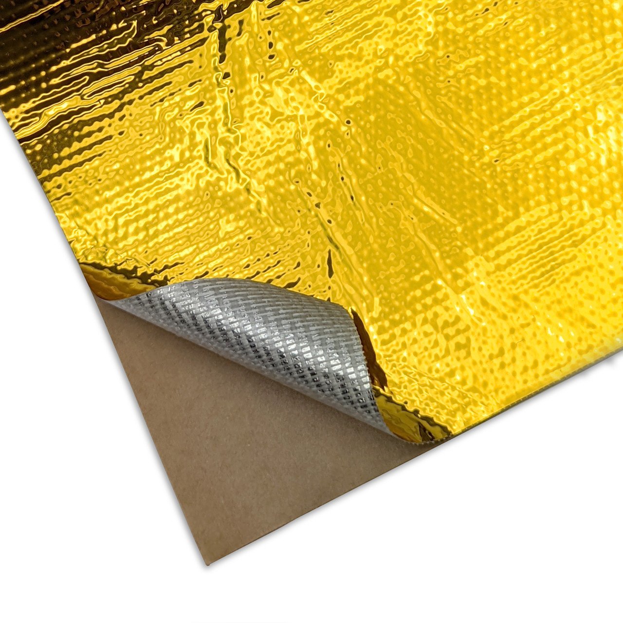

That is what the Proof-of-Concept gantrywarmer does 🙂 see https://github.com/matti125/gantrywarmer. It might be good enough for some cases, and sometimes it might be good enough to just heat soak in a single place even. Heat soaking for long periods with full hotend temp is not without issues, one of which is the potential carbonization of the material. Also, you need to establish the real z-height after the heat soak, and with a very hot nozzle you cannot use beacon contact anymore. Those could possibly be worked around somehow, but it might not be a snap of the fingers kind of thing.
Certainly, very interesting. Need to try this out!
I was more curious if it would distribute the heat evenly enough that it would negate the warp of the initial heating. Once you are printing I would imaging there would be enough movement to prevent the localized issue and be more evenly distributed.
Hot end elongation after reaching temp seems to be consistent, so that should be an easily compensated adjustment.
I still believe shielding or alternative airflow to prevent exposure altogether is the ideal solution.
That is the direction we are now going towards. But the bimetal effect is not only caused by the hotend, the chamber temperature causes it as well. And while the chamber effect can be mitigated with long heatsoaks, an ideal solution would reduce the time for those, something that could be achievable with combining heat transfer reduction with a decreased bimetallic effect. But pretty much everything in engineering is a compromise 🙂
Right. The bimetal issue is not an easy one to resolve without other compromises.
I think the PrusaXl and some other printers appear to use Steel X linear rail supports. I feel it is better to fix the root source of problems where possible rather than try and mitigate them. It is time for Rat Rig to address this issue at the root of the problem instead of people having to come up with band aids.
I think you guys have done a very good job of root cause analysis but it is now appropriate to have root core correction.
While using steel is an obvious choice for getting rid of the bimetal structure, it still is not clear whether it is the obviously best solution overall. We do not yet know how it will affect other performance metrics, including speed and quality. Once those are known it will be possible to select the best - or optimal - solution.
And it might be that even with a fully steel structures there can be some bending, due to temperature differences within the structure. Thus, it would seem like it makes sense to try to improve how the heat from the hotend is contained/managed.
But yes, fixing the root cause is usually the best way forward. We just need to make sure that does not cause more harm than the original issue 🙂
I think we have a good indication of how titanium (or a similar weight steel- if possible) linear rail support would work from the many people (like myself) already using this solution.
In my case it is unlikley that there are any further gains to be had from improving how the heat from the hotend is contained because I don't have any issue to detect an improvement on. It may be that some people using titanium tubes still have some residual issue. The other plus to the Titaniumm support is of course the lighter weight of the Y gantry.
From an academic view point your research is interesting.
Yes, very true. And now that I re-read your post I realize you did not actually suggest that steel would be the way to go. It is one option, but so is titanium, or perhaps a hybrid structure of some sorts.
It might be that good enough results can be had with no containment, but vc4 has has a longer gantry than vc3, so it not yet clear how transferrable the results are. But rest assured, we are not assuming that the current alu/steel is the only way forward, or that it could not be improved.
One way to get a gauge on the effect of a longer titanium tube vs a shorter one is to look at the resulst of 500 vs a 300 using a titanium tube.
If looking at exotic options, may be worth looking into a carbon beam or dual carbon rod setup like Bambu is using on the P1 and X1 series printers.
A setup similar to Bambu’s would leave plenty of room for airflow.
Did you try creating scan compensation profiles for the filaments you use? That solved the issue 100% for me. #1293322335545196655 message
Looks like you have a 300? If so, that's a far easier beast to tame than the larger machines, particularly the 500.
Yeah, I tried scan compensation and heat soaking. Heat soaking worked about half the time. Scan comp didn't do anything for me. Reversing the fan also did okay but I was nervous about heat creep. Even put on a 4020 fan to run reversed, but that added a ton of vibration.
I installed the titanium tube yesterday. So far, seems to have solved the problems.
Good to hear your experience. I am also a bit worried about heat creep, but since there is some success in running even totally without a fan, I'm interested in seeing first hand how that works. Did you encounter any clogs/extrusion issues?
Curious if titanium backing plates would help? I know they are used by the Voron crowd.
Have to see if I have any issues with the VC4 500 at work once we start printing. Maybe I can convince the boss to buy a small sheet to laser cut some backers from and test.
Have to see if our suppliers can get the material cheaper than online metals. To get a 1200mm long sheet is more than we spent on the entire printer kit. 😳
Those should help. I was also thinking about them as an alternative to a fully titanium gantry. Perhaps even a carbon fiber backing could help, as it has a negative coefficient and would thus have more change in shape. I have not done any calculations.
The advantage to the Ti tube is the weight reduction in addition to the other benefits. Adding titanium and hardware only makes the stock beam heavier.
I am curious how carbon rods, like the Bambu P1/X1 series would do. 500 is a significantly longer span and more weight, especially with IDEX.
I didn't print enough with the stock fan reversed to confirm if there was ever going to be a clog. I printed maybe one or two flat sheets to test leveling. There weren't any odd behaviors in that short time, but again I was nervous about taking the chance of clogging it by pushing it.
So I switched it for the fatter fan (reversed) and the increased airflow I could feel instilled confidence, but by this point I already had ti tube on the way. The vibration was more of a noise complaint than anything. I printed a few small test things, like bed leveling sheets, and also the parts needed to install the ti tub, without issue.
I made sure to orient the ti tube parts along the Y axis so that the X didn't have to move as much and can stay in that heat soaked area for the majority of the print. Having the long parts oriented along the X axis were impossible to print.
I suspect you would have you increase the diameter of the carbon ros to cope with the longer sun of the 500.
The good thing about using rods made of any material is that like using a bare linear rail there is no bending due to dissimilar materials having different thermal coefficients of expansion.
I used a bare linear rail on a 300 with great success in the past.
Me too, still running it..
The only two reasons I stopped using it were:
- Improve Beacon touch probing accuracy (although I noticed no degradation in first layer quality)
- To test the Titanium rail for @fading ermine and give him some feed back.
I have kept using it, because with my newly installed 3.1 hybrid upgrade kit I doubt lightening the Y axis will have much effect on IS recommended results (From tests others have donewith the hybrid upgrade it seems that weight savings on the gantry have much less of an effect than before the hybrid upgrade)....but at some stage I will probably remove it to be sure. As X recommended IS shaper results are less than Y for some of the people who have upgraded with the VC3 hybrid upgrade kit, it seems still worthwhile to run the Microlight print head though.
Makes sense. The probing repeatability I get with a mechanical euclid probe is a few microns. It is way more than with vc4 and Beacon, but still inconsequential compared to other errors in the system.
no issues with rigidity with a bare linear rail? how did you go about it... is that a viable option instead of toro tube on a 500?
I’m sure there is a compromise between rigidity and ease of use. In my use case the quality (rigidity-wise) seems good enough. Someone might have different needs, but as I print mostly functional parts, some possible ringing is not a real issue. For decorative stuff that might be a dealbreaker. But I have not done a thorough, meaningful comparison with the stock, so I cannot really say how much worse it is. Good enough for me and really nice to print without heat soaking 🙂
I would not think it is a viable option for a 500 unless you went reeeally slow. But this is based more on a hunch than real experiments or data.
you did this on a 300? Im having this issue on my vc4 400 and Im gonna buy the toro tube, but currently its not in stock so Im thinking Im gonna try without the extrusion. Did you use short 20x20 alu extrusions to fasten the linear rail, or is the linear rail fastened another way?
I did it on vc3 300, which has a shoter gantry than a vc4 300, and vc4 400 is yet longer. I would not bet on success with the vc4 400, but certainly would be interesting to know. For fixing I printed just short stubs, as I was too lazy to cut a proper alu piece. I've since ordered an out-of-spec stub of ti tube to be used instead of this plastic piece, but have not yet found the time to install it. And... it works, so I have less of an incentive to fix it 🙂
Sounds like that might be a bit troublesome for my vc4 400. But having to do 25 minutes of heat soaking to be able to run a test print is seriously eating away at my patience 🥲 And it doesn't really work anyway. I guess I have to try this out.
How is it going with titanium, did it solve the bowing? I have to heat soak the gantry for an hour if I want to print something with 100c bed temp, that’s annoying
I don’t really have problems I heartsoak for 30min (with ti tube and 500 printer)
Did you check the heightmap cold vs soaked?
It’s a different of 0.2mm
You in the US? Lukes lab has some 400 ti tubes. https://www.lukeslabonline.com/products/toro-titanium-tube?_pos=1&_psq=toro&_ss=e&_v=1.0

Lukes Laboratory
The Toro-Titanium-Tube is a lightweight tube designed for enclosed printers. Instead of threads directly cut into the tube, DIN 6926 locking nuts with a flange are included. They are fastened using the either of the tools listed below: Wrench (requires strong Material) – designed by billydNut holder strip – designed by
Norway 🙂 thanks for the tip. I managed to get one from Toro3d so it's solved and titanium tube is on the way. Really hope this fixes the bowing and reduces the time required for heat soaking.
You would be the first person were it doesn't 😄
I have high confidence in it solving gantry bowing! I'll report back with the results once it's installed and tested.
what's your numbers now? I am thinking about ordering too, mine are from 0.213 to 0.9 in 50 minutes at 105C bed
I havea 400 and the difference is 0.0x, where x is rarely more than 3-4. So around deviation of 0.04 max on bed with 100*C
That is very impressive
It's great the only thing to look out for is saddly titanium is hard to mill so the starting deviation is what you basicly get. My whole bed and gantry is around 0.1 together so me happy. 😄
If VisualTech is happy, then I am happy 😄
is 725mm expected to be in stock someday?
Yes, in roughly 3 weeks 🙂
Entirely resolved. I do not hestsoak for more than whatever the default is set to.
I also had issues with a grinding noise seeming to come from the Y rails when making curved motions (like printing a cylinder) and this is also resolved after installing TiTube.
I made a nut holder to help installation and posted to printables and in the discord mods thread.
Beacon measures a range of 0.326 at room temp, then after 1 hour on 100 degrees celcius it stabilizes on a range of 0.334. However, the bowing has flipped direction, so the effective distance of the center of the bed has moved about 0.6-0.7mm.


That’s stock aluminum profile or titanium?
Stock aluminum profile. Titanium is soon here.
I'll do the same test after installing the titanium.
Just wanted to share my results on a 500 at 110C.


I’ll share mine as well once I get my printer up and running again
Hello, any news on this ? I'm planning to get the titanium profile when it's back in stock, to get rid (hopefully) of very poor first layer quality and big inconsistencies printing ASA at 110/260 C on vc4 500.
In my case (vc4 500) the titan tube + 30 min heatsoaking with the head 2mm from the bed away it is no problem anymore
@fading ermine are you guys taking any pre orders? I convinced my company to buy a vcore4 500 and my boss is skeptical on the performance now so this new gantry bar would really help me keep my job lol
I'll DM you 😄
This is a test I did with the new toro titanium tube on my enclosed vcore 4 400.


The last image is from my home assistant that stores the variables. The graph contains the temperature data from the cold nozzle and the heated bed, together with the x and y movements. The heightmaps timings correlate with the movements visible in the graph. The nozzle was located at "homed" x200, y200, z15 during the entire test, except during the movements.
I think the images show that there is a clear improvement compared to my previous test which used the original aluminum extrusions (see a few posts up from this, Im blocked from linking to my own posts apparently..). The results aren't perfect. I can see a difference between 25 minutes and 105 minutes of heating at 100 degrees. Could maybe be the other axis with its aluminum and steel sandwich which I guess will twist slightly as well.
Yes, a system with the Ti tube does deflect somewhat, but way less than with the alu. The "deflection vs time" profile is quite different, and we are trying to figure out whether that could be caused by the lower thermal conductivity, and what could be the best ways to mitigate the non-monotonicity.
Here is a test where I measure both what the beacon sees as the distance as well as what a dial indicator sees.
7:45: bed to 60, hotend to 150, part fan 100%. Deflection at 0mm
10:05 bed to 80
12:56 part fan off
13:54 hotend off
14:53 bed off
At 19:48 there was an audible snap, something probably overcome the stiction and popped back into place.
This is with an experimental toolhead housing, so it might not be exactly one-to-one applicable to the stock situation.

Well 0.1mm deflection compared to my 0.7mm is pretty good improvement
Have anyone already tried something like this ?

Yes, I tried the “original” Reflect-o-gold (that costs €30 for a 600x600 sheet) with the Ti tube, but the results were underwhelming. There was a resuction of perhaps 10..20% of the max deflection, which was good, but unfortunately it did not seem to change the temporal profile too much. So it seems to have some, although minor effect.
Hmm okay I already installed it so I will let it on I mean 10% are 10% (I also installed it on a ti tube
This means you would recommend the ti tubes over the aluminium extrusions?
100% yes
nice to know. i finished my build today 😄
Haha
And if you have the money the mandala rose cnc upgrades
And then the heavy duty idler 😂
And then the chube hotend
dont tell me that i should do a 5 days maintenence after performing the initial setups...
And and and 😂
I mean the standard is also good enough for most of the people but if you want the top thing …
Rapido V2 UHF, Orbiter, IDEX 500 thats what i got right now.
I also got this but then I go back to one head
And build it with the cnc parts + chube + orbiter v2.5 + ti tube + heavy duty idlers 😂
I mean we Need to do something
Just printing is boring 😂
what is the outcome of this thread regarding the z offset? pointing at the standard printer
Everyone sticking their head in the sand and acting like it isn't a problem, or accepting that the only fix they are going to get is via a third party part lol
Yes. As the expansion coefficient is of ti is lower than steel, the gantry will at some point start bending upwards, not downwards as it does with alu. The initial bend is still downwards, probably because of heat from bed and the different thermal conductivity and mass of the tube (We are yet to figure that out). However, the upward bend is rather slow, so that in my vc4 400/ti/custom hotend housing, 60C bed, 20min heatsoak, 0.2mm first layer I can print without babystepping as long as the first layer takes less than 20mins. At around that time the print could use about 25 microns of babystep closer to bed. With a thicker initial layer I’probably be ok still, but I intentionally use a thin first layer to see the effects.
But yea, the ability to just start a print and not have to check/babystep is quite nice 🙂
Even after heat soaking for an hour in an insulated chamber at 50c, I still have to z-offset the first layer by quite a bit.
Need to order a small sheet of titanium and some titanium screws to try making a backer set on the laser at work. See if that even helps.
It should. With proper geometry we actually should get zero steady-state deflection, i.e. the different coefficients would cancel each other out. However, getting to that steady state there could/would still be some deflection. But using the titanium backers is something I’d like to check as well
I’ll keep bugging my boss about it and see if he will green light it. That or get him to agree to ordering a Toro Ti Tube. Would probably be cheaper to order the tube. Haha
Just order the tube an be happy 😁
Believe me, if it was my machine and my money, it would have already been installed, along with some other machined goodies.
Ok thx. Placing a steel bracket on the bottom of the aluminium extrusion doesn’t help? Anyway, how hard is it to exchange the aluminium extrusion with the ti tube? Is it possible to disassemble it from the bottom onwards without taking off the belts completely?
No you need to take off the belts
Estimated time for a swap? 6h?
Yes should be okay
Is there any source of these tubes in Europe with the correct hole spacing?
Toro 3d is from Germany
I mean him
Adding a steel backing would help some, but not as much as a titanium backing of the same weight.
The advantage of a hybrid solution with an alu extrusion and a ti backing, compared to a full ti solution would be that the alu extrusions are cheaper to get in tight tolerances for thickness/straightness/twist. The ti tubes tend to have more twist/bend than the alu extrusions. But there could be many downsides to such a structure as well.
i looked it up. it is available again mid april.
You could contact @split sun
He does clinch nuts and has some tubes left
Is there maybe a way to use the beacon as a live offset sensor? So that the beacon adjusts the z offset while printing the first layer.
no
Or any data could be used for a macro? Like a temp sensor from the toolhead to add a equation to the hightmap which is based on the temperature as a variable
this wont work
why? you know the direction, you know the physics, if you have only one variable, then it should be possible. you also know the x position of the printhead. the difference of the non bend extrusion to the extrusion trace of the deformed one gives you the correction factor. in theory it should work. why do you think that it wont?
bc the temperature is a useless value in thsi equation bc the bow effect depends on multiple factors and not every machine behaves the same. more important is that klipper uses a look ahead approach which doesnt allow live changes while printing
if you want to limit the bow effect aligne your x and y rails and the gantry extrusion while the printer is heated up and everythng has heatsoaked
yes, i am heating up the printer 15 min earlier and then its fine.
how far does it look ahead? because if you have the hight map, the correction factor, you can calculate the offset and use the calculated hight map instead. so, if you do the calculation on each layer change and redo the hightmap with the factor applied, then it should work. technically it should work. and yes each maschine is different. then the correction factor is something you have to test. like pressure advance. its also different for each setting
Just 15 min ?
I do 30-45 mins
Just speculation as I’m still fairly fresh to klipper and what not. If you do a slice, look through the g code commands. The code looks ahead I imagine meaning it is only looking where to move next. There’s a lot of commands in there so you’d have to figure out when to place a beacon point (if that’s even possible), it would then need to recalculate/interpolate or something.
That’s fine but, it then executes its next move. Ok, what happens if the nozzle/beacon is higher vs lower. If it reads higher than initial mesh at that spot, it’ll adjust downward right? Well crap, you just adjusted downward when the upcoming 8” straight line move actually has high spots that are larger than the interpolated difference along that path. Then your nozzle digs across the build surface.
This not accounting for the beacon offset as well. This would be if the beacon is perfectly on your nozzle point. Makes it even more complicated.
I do belive that in theory the live update should work, not by fixing every move, but instead maintaining the height map and adjusting that slightly. However, when recording the proximity values during live prints, the height values seem to be very noisy. This does not meant it could not be done, but at least it is more challenging that I first assumed. Adding to the issue is the drift of the beacon (or its moun) during the print, which would need to taken into account.
So, I’m not writing off dynamic/automatic babystepping, but saying that it is not as simple as it sounds 🙂
live adjsuting wont work in klipper, even if you change the height map. if you are at positino xy, this move has been planned long before and cannot be changed again
thats a change that would needed to be implemeented into the klipepr firmware that runs on the mcu
not in python
I did not say we have to do this with klipper 🙂
This would only be for first layer though. Beacon is eddy current, correct? It wouldn’t sense the plastic.
True, but it works for several mm of height
My suggestion was with the temperature deflection and as the temperature as the only variable over the movement on x. And with this factor the hightmap will be updated and used for the next calculation
And the Beacon is offset from the actual nozzle, so live reading would not actually be the nozzle location, unless it was coordinated with the initial scanned mesh and then compensated relative to current sensed height location and projected to the nozzle location. Sounds very computation heavy and messy.
The challenge there is that we have several components at different temperatures, and getting the full picture is challenging.
True, but if there is a twist/bow of the x-rail, it would have to be constantly changing value based on x location on the curve, assuming the curve is a consistent and predictable arc.
I’d think math is not the issue here, other factors are way more challenging
Exactly. It’s a deep investigation. Going more into the konservative direction leads to a compensation which is very slightly. The further you push it, the better it will be. But this needs more effort to do.
The challenge is the investigation.
The basic equation is the same for all printers. Only temperature and the correction factor for the equation is different.
Yea, and it would need to be many temperatures, quite probably. Or an accurate model of the transfer function of the printer and well-controlled/measured environment.
And as @rancid berry pointed out, with the current implementation of klipper we cannot fully compensate the shape change while printing. It is easy to shift/babystep, which might be enough for some cases. But a full dynamic compensation while printing might need some non-trivial software changes as well
Well…. That’s not really true. It’s more or less a linear equation. So you only need two temps. A cold temp which could be calculated with the beacon on cold conditions. Then warming up the printer and the heatbed and do the hightmap again. With these two set points you can calculate the deflection or bending of the x gantry.
True, you have also a bending of the print bed itself. But this could be equaled out by taking the y variant into account. You also get a correction factor of the initial correction. So with 1 you have 100% of the theory enabled. With 0.5 you multiply the z offset from the correction equation with only 50% which would be very conservative. In the end it could be a fully automatic calculation with the human who is just doing the manual correction with the factor.
I have a slightly different view of the challenges, but you are ofc free to show me wrong 🙂
I am just a mechanical engineer, not a programmer 🙈 so if someone is able to code it for me, we could develop something suitable and see if it works 🤷♂️
if you are able to make it work, than only on your machine. not on all machines. you can have two identical machines, at the samee temp, but they will behave totally different.
this depends on so much more than just temperature
That’s where the correction factor Stepps in.
how one has assembled and aligned the gantry and the rails plays a much bigger role than temperature
The mechanical properties are equal everywhere
yes, but then you need a tuning and compensation for the compensation, thats not a viable way
better woul dbe to fix the hardware, or to jsut measure with the beacon when expansion and bowing has finalized and then to start the print
its highy unlikely that such a change will find its way into the klipper mcu firmware
That’s how it is done in many usecases in the industry 😂 you always correct the theory with a correction factor to get it suitable for the use case
It’s more likely a macro for ratrig, not a firmware change
nope, trust me
A macro will not be able account for shape change. It will be able to babystep. Those are not the same, and in some cases a babystepping might be sufficient, but not in all cases
Full shape change compensation would need the ability the affect the look-ahead calculation of the z position for future moves
Hmmm ok… this sucks….
Oh, i think I understand where part of our difference in views comes from. When I say several temperatures, I do not mean that we need several temperature measurements of the same position or component. I mean that we need the temperatures of several positions: the temperature of the top of the gantry, bottom of gantry, top of rail, end or rail, beacon mount, bed mid, bed sides… and all of these temperature points have different time constants. And they all affect the drift. To estimate their actual values you’d need to know how they behave as regards to time and different components being on or off, or the door opened or whatever. There is unfortunately no single magic temperature that would tell us what the state of the printer is.
Well…. Not really, because this all is connected to each other due to the thermal conductivity. You mainly need one temp. The gantry is parallel to the print bed. So the heat is coming from the bottom. If you have one thermal sensor somewhere near the gantry, you can get the offset of the measurement from the sensor and the temp of the gantry. You can mainly calculate the temp differences between the bottom and the top with the conductivity and the radiation. Both are natural constants for the material. With this you can calculate the internal stress of the gantry.
The only tricky part is the offset from the measurement from the sensor and the vital mean temp of the gantry.
That’s why I wanted a linear equation which is by nature an average of everything. With the 0 line at room temp and the offset line at 50°C heatbed temp for 15 min and a 2nd offset at 100°C (for controlling) you can create a linear offset correction factor.
It’s more or less a parabola. The factor calculates how stretched this is. And the amount of the difference between the zero line and the calculated Center line will be your correction factor for the x position.
And with the human factor, or the correction for the correction you multiply the difference with factor x to make the compensation a bit less. From the physic point of view you do not need so many different spots to get the temp. If we would do a phd, then yes, would be interesting to see how this behaves. But from my point of view a linear outcome should be the best to compensate it.
The other, more easy solution is to heat the printer up, wait until the temp is stable and do the hightmap. That’s how it should be recommended without any correction. Because then you have a near steady state situation with the thermal bending.
Problem is you have a 200c-270c heater that is blowing hot air on the front side of the gantry rail in one or two locations with one or the other moving back and forth in different locations for various time intervals. There will always be localized heating and cooling happening.
So the only 100% solution is to use a steel x gantry 🤔
Titan works also quite good
Needs to be something more thermally stable to prevent the distortion. Titanium is good. Carbon fiber would be good too.
Need to put some guides on some borosilicate rods and do a cross gantry setup.
What you describe is the transfer function of the printer. I encourage you to develop one 🙂
I am not totally joking, as since we do no computational compensation today, any compensation could be better than the current. It is especially true for the seemingly monotonic drift we see with alu ganty. It might not be true for the non-monotonic drift with the ti tube.
klipper has the “z_thermal_adjust” feature that you could try
Have anybody tested with ptfe washers between the screw and the linear rail 🤔
ChatGPT says that this will help a little bit
Not much but a little bit and we just need a little bit 😁
I will order some and test it
Interesting. I have to look it up what it actually does
And what is with something like the Oldham couplers but only in one direction
It’s so crazy annoying… the bimetall effect
I preheat 40 min have the to tube installed but still the first layer goes up after 10 min 🤓
Is here anybody who wants to use a steel x gantry ? I’m thinking of to buy one and if we order more then the price is going down.
The weight of the steel tube is at the moment 480g I will look at it again to reduce the weight more
This does not fix anything z related due to a thermal deformation from the x-axis
Yes it does
We have this problem because the steel and titan have different temperature Expansion
And because the two are tighten together it bows but if they can move in x direction then it doesn’t bow
Oh you mean that the steel rail has a fixed bearing on the one side and a loose bearing on all the other connection points. Then it would work.
Yes
Anyway, Titanium has a significantly lower thermal expansion coefficient than aluminum and also lower than steel:
Titanium: approx. 8.6 × 10⁻⁶ 1/K
Steel: approx. 11–13 × 10⁻⁶ 1/K
Aluminum: approx. 23 × 10⁻⁶ 1/K
Since a steel rod is firmly screwed onto the top of the titanium tube, temperature fluctuations create stresses between the two materials, as titanium expands a bit more than steel. This will lead into an positive bow effect.
Steel expands more than titanium when heated. This means that as temperature increases, the steel rod will try to expand more than the titanium tube. Since the connection is rigid, this will create compressive stress in the steel and tensile stress in the titanium.
If minimizing deformation under mechanical load is the priority, steel is the best choice. If weight is important, titanium could be the better option.
Yes later I will design a steel gantry and will look at what weight I can come
You definitely have to take the moment of inertia of area into account when designing one by yourself.
You mean the weight ?
I will take off as much material as I can
No I mean the moment of inertia of an area.

The area moment of inertia (also called the second moment of area) defines the resistance of a cross-section to bending, due to the shape of the cross-section. It is a key parameter for the analysis of beams and columns.
In this video I take a detailed look at the area moment of inertia, how's it calculated, and how it's used. I also cover key ...
Ah yes I will test an C as design but with the open side on the button I think this should work
C is very weak on torsion.and the printhead gives some torque on high speeds. open profiles shell only be chosen if you do not apply any kind of torque to the profile itself my professor said. maybe do a FEM analysis
.
This is the actual design


This is the top

Yeah, that’s not an open design 😉
Yes haha
What do you think is a good thickness
2mm or 3mm
I can’t tell you from my stomach. Go to the toro 3d page, there is a video which explains how you can calculate everything. That is 100% mechanical engineering stuff and you have to calculate it with the formulas.
I was going to run a stress analysis for steel as well but doing some quick maths, I was looking at a gantry that’s at least 5x the weight of the titanium tube. Here is a supplier I found though as you’ll need to get 440 steel otherwise it’s a useless pursuit. Only other option I could find for 440 was buying by the ton from china. I couldn’t find 440c in tube form so flat stock seemed to be the only option.

If anyone is curious I did basic stress analysis tests on the toro tube and funnsor tube. Not super precise but enough to see how acceleration and bending stresses affect them.
At that point you might as well just strap two linear rails together though
Why do I Ned 440 steel ?