


1 messages · Page 1 of 1 (latest)
I'm trying to build a self-balancing cube, so I guess I'll journal a little about the PCBs and electrical designs I'm thinkign about.
I had initially planned to use a DRV8313, but when I got a test SimpleFOC board I found that with my 380kV motor there was not nearly enough torque. Also it seems that with low-resistance motors (mine is 40mOhm) the current estimation features of the SimpleFOC library aren't effective at generating the full available amount of torque.
My plan therefore is to design my own DRV8304 board with 3x motor output channels. Before I waste a bunch of money building a whole board, my intention is to do a smaller dev board with just one motor channel, and make sure I can get a 1D frame working with that. My thinking is once I've validated this layout, a lot of the risk of the project is behind me, since I can just apply the layout three times to the final board.
Here's what I've got so far:
I have a few big questions right now:
Any feedback would be appreciated and will not fall on deaf ears.


what's actually driving the DRV ic? I recommend copying a moteus board and running moteus firmware, it's extremely well documented and very mature with tons of features, will save you a lot of headaches imo
My plan was to drive it with an ESP32-S3 running simplefoc
I will have to modify simplefoc a little because it currently only supports two simultaneous current-sense'd channels on the S3 but I think physically the S3 can support four.
I'd plop an stm32f407 on there and use moteus. simplefoc is not very well developed imo
! I appreciate the advice. For now I really do not want to learn another SDK, but I will keep it in mind for my next robotics project.
I think the other issue is that this robot is gonna have three motors, not just one. From reading about Moteus, it seems like it's designed to run a single motor from an STM32, controlled over the CAN bus? So I'd need three STM32s to run the motors plus a microcontroller to control the entire thing. In my design, there will be one ESP32-S3 running all three motors, plus reading the IMU and performing the balancing calculations. I think if I were designing a purpose-built motor driver to drive a single motor Moteus would definitely be the right ansewr but unless I'm missing something i'm not sure it's the right answer for this project.
yes the stm32 is just for running one motor
does the esp32 have the processing power and timer/adc/etc peripherals required to do foc on three motors at once?
theoretically yes, but it all depends on the implementation. Motor control is really not that computationally resource intensive if done right
ADC is done by the Ti DRV btw
that drv does not have an ADC in it
No the ADC is handled by the ESP32
SO, it's going to be a programming question, but I believe it should be able to handle it. One core will be dedicated exclusively to FOC
what timer peripherals will you be using?
my understanding is that the foc calculations will be about 5usec per motor of cpu time, so the real question is "can we do all the other stuff."
The MCPWM will interrupt us in the middle of the off-portion of the PWM duty cycle
I'll set up the MCPWM banks such that one bank interrupts 180 degrees from the other one.
We'll read the ADCs using DMA, which I'm given to understand that for bank 1 ADCs you can fire off all four ADC reads as a single command (this is sort of true. YOu can start one DMA but you read each ADC sequentially)
And while the ADCs are running, we'll do the SPI reads for the encoders.
(I'm pulling up my numbers for how long all that is meant to take
It's about 2us for the ADC reads and about 4us for the SPI, for the chip I'm working with
So you start the SPI transaction first, then kick off the ADCs, wait for all that to be done, then run the FOC calculations.
About 15usec per cycle for the MCPWM that has two motors on it. Less for the one that has one motor.
I only want to run with a period of about 30usec so maybe it's okay!
Sorry that's not correct, I don't need to run at 30usec period. I can go as low as 12kHz without it being too much of a problem, but I'll go as fast as I can get it to run jitter free
oh yeah, hm. Might make sense to have ADCs on the board in that case
I'm gonna use the ESP32's ADCs. The noise is on the order of 10-30 mV, which is not ideal, but they're a lot faster than SPI and that counts for something. 🙂
Added a TVS there in between the battery pads, and did some silkscreen work. I think I'm going to order a set of these and see how we go.

Also I realized all that firmware stuff that I said was nonsense. The main limiting factor is the ADC conversions. We can get one of those done every 2 usec. Four usec per. This limits our PWM frequency, because as the frequency increases the maximum duty cycle decreases. With a PWM frequency of 30khz, we can get a maximum 75% duty cycle (assuming the ADC reads are centered on the low portion of the pwm). That's okay for my purposes, since I have 380kV motors (16V batt * .75 * 380 = 4560 rpm) and 4500 RPM would already be dangerously fast for a 3D printed reaction wheel. And then regarding the rest of it, we need to be able to do a complete FOC calculation in about 33 usec, which should be easy for the S3. We'll do one motor's FOC loop each MCPWM cycle, which means that each motor will be updated at about 10khz, which is fine for motors that can't spin faster than 4500 RPM (11 pole pairs * 75 RPS * 10 exec/electrical revolution = 8.25kHz min freq.)
place it as close to the half-bridges as possible. Will you be using regenerative braking?
I don't intend to regenerative brake. It's only for emergencies.
yeah that makes things a lot easier
My understanding is the thing uses relatively little energy if tuned properly. Can stand up for 45-60 minutes on a battery charge. Not that I'll ever actually run it that long.
sure, but I'd worry about the startup phase. Do you plan on have it be able to stand up from the fallen position?
No, it is impossible without a physical brake, and I am not so interested in designing that.
Might also require machining and who has the time (maybe someday tho!
)
Well I guess I shouldn't say impossible. Perhaps electrical braking would work but . . . I do not have the skills to calculate whether it is or it isn't, or whether it will be viable using reasonably acquired hardware
The only group i've seen that did it were the cubli group and they used a servo brake
I was doing some research and it seems perhaps I made a mistake on this design. The 470uF capacitor only supports 650mA of ripple current. Given I'm going to be pushing 16A with a PWM of ~30khz, I'm told that we calculate ripple by doing $$I_{rms} = I_{load} \sqrt{D(1 - D)}$$ That gives us about 3.5A of ripple already at our 5% startup duty cycle, ramping to 8A at peak. Apparently this is going to cause a cap with 650mA of ripple current tolerance to explode.
So I guess I need to rework the PCB to include a few caps in parallel that support a higher ripple current.
that's assuming all the current comes from the cap
do you have an impedance graph for the capacitor? those are usually really hard to find (unless it's a murata haha)
I don't know if I do let me check
I do not have an impedance graph, but I do have a ripple current correction factor, which is 1.7x. Presumably that relates to the ESR?
My datasheet doesn't even disclose the ESR of my caps: https://datasheet.octopart.com/ECA1HM471-Panasonic-datasheet-182100706.pdf
Okay, this is all beyond my knowledge, but according to my searching, in power electronics they typically assume that 100% of the load is seen by the capacitor because of engineering tolerances and also because it is typically the lower impedance path (after you account for the reactance of the battery wires at the motor's switching frequency)
depends on the ESR of the battery + wires and the esr of the capacitor + traces at switching frequency. Kinda hard to model. Could add some MLCCs close to the transistors, but you're also running with a very high voltage safety margin. Could try a higher voltage battery to decrease the current.
I did some modeling:

It appears that C1 sees about 5A of ripple, which is 10x what the component I bought can handle. I'll have to adjust
(note that the cap models have their estimated resistances and inductances modeled in
)
means the cap can handle 1.7x the ripple current at 10kHz
Right I get that I just wasn't sure what it means for ESR in specific
Okay apparently there is a formula for the ripple current of SVPWM, which is 50-60% of motor phase RMS current
That gives me an expected capacitor ripple of 6.2 A
So I gotta get something that is north of 2A and then put four of them on the board
or something like that
Maybe Panasonic EEHZS1H151P
ESR is ~0.34 ohm@120Hz, could be around 0.03 ohms at 10kHz judging by graphs not sure
I'd still recommend just placing something smaller physically close to the fet. The bulk electrolytics are usually for absorbing voltage transients, might have a look at polymer caps as well
check: KEMET A781MS157M1HLAS028
I don't understand. These are more or less the same size as what I'm planning to place?
They also only tolerate a 550mA ripple current
New general layout idea:

Haven't routed yet will have to do after dinner.
oh yeah, they do specifically say 6.6A with a heatsink tho
ah I see what you mean, no that was just my recommendation for a bulk cap
I meant like add some MLCCs close to the fets
I don’t know how to think about how the mlccs reduce the ripple current on the main caps. I’ll have to simulate it
Okay, adding MLCCs will help with high frequency switch ringing, but it won't help with the lower frequency current demands. Reactance is Xc=1/(2πfC), which if you put in some 22uF caps would give about 500 mOhms of impedance. Even though it's ESR is much lower than the larger electrolytics, it's reactance is higher at low frequencies, and therefore most of the current demand for the motor switching would be supplied by the electro.
There actually already are some 1uF caps (see C9, 10, 11.)

All routed. Same amount of capacitance I think, maybe a little more, but way more ripple current tolerance. Up to 8A, where we think our maximum is around 6A.
You can view the impedance graphs directly, about 1.1 ohm for 10uF 0805 or 0.4 ohm for 33uF at 2220 sizes. Better to squeeze in a couple 10uF caps imo
you can also compare with the amulet controller, they only have MLCCs, while running with way less headroom.
Yeah, they appear to have about 100-220uF of capacitance on that controller, just implemented via a large number of MLCCs rather than a smaller number of bulk caps. Cheaper BOM but if you're not paying for assembly the board is quite a bit more expensive after you account for your time.
oh no, not cheap at all, those MLCCs are actually quite expensive. A lot more than the polymer caps you have. DC bias derating to 100uF btw. My point is more that you definitely don't need that amount of capacity on the board.
Also regarding the ripple current: people have run hoverboard speed controllers at 40A phase current at ~36V, and those have dinky little electrolytes on them, never heard of them overheating. Issues were usually related to voltage transients from regen braking
And they were using SVPWM FOC on those boards? I don't really understand how that is possible given the research I've done.
I mean, one thing that is possible is maybe they just had a lot less total capacitance, and thus the ripple current was reduced at a cost of increased ripple voltage? If you're starting from 40V you can probably tolerate quite a bit more
I could probably tolerate more than half a volt
Can you point me to such a hoverboard controller?
Cause I'm looking at stuff like https://www.vesclabs.com/product/vl-minim-100v/ and or https://www.alibaba.com/product-detail/Flipsky-ODESC-V4-2-24V-Single_1601627901283.html and I'm seeing bulk caps everywhere.

The VESC Minim is a 100V motor controller capable of 50A continuous current or 65A burst current
yes, foc, not sure about their exact pwm method
here's a github with some info: https://github.com/EFeru/hoverboard-firmware-hack-FOC

With Field Oriented Control (FOC). Contribute to EFeru/hoverboard-firmware-hack-FOC development by creating an account on GitHub.
I can check my boards later, I have a bunch in the basement. But I can guarantee it's the cheapest chinese aluminum electrolyte caps
lemme know.
the first one is also liquid electrolytic caps though
I don’t object to liquid electros
It’s just my first one had only one rated for around 1A at 30khz
If I had three and there was active cooling
It might be a different story
no active cooling on the hoverboards I can guarantee that
Well there is the airflow of the hoverboard moving forward, at least.
not really, it's completely enclosed in plastic
Will be interested to hear about the properties of those electros.
I checked, it's a small 22uF and 47uF near each half-bridge, and 220uF bulk. All electrolytic and rather small sizes.
so 1x 220 and 3x22, 3x47
That’s a similar amount of total capacitance as to what I put on my test board. Actually slightly more.
I ultimately decided to switch over to stm32 for the processor. I was thinking about using an fpga and part of me still wants to but another part of my recognizes it’s impractical. I will use the g474 instead since it seems designed to purpose.
sounds good, anything that has an FPU will do for a clean FOC implementation. Theoretically it can be done using integer math only, but I have yet to see some human readable code for that.
Ah yeah it's more about the ADC quality and interrupt latencies. STM32 delivers 12 cycle latency compared to hundreds of cycles for ESP32, and also can trigger the ADC and SPI transactions without any CPU involvement from the motor timers.
Also has two ADC banks that can be trigger simultaneously, so I can current-sense both phases at the exact same instant.
hrm good to know, hadn't considered that
Been busy with some various things but I finally got around to assembling my test setup for the drv8304. Now I gotta do some programming.

Good enough, at least as far as I've been able to tell. All the joints look okay under a microscope to the best of my ability to see. Next thing is to actually wire this up to my stm32 and see if it works. Some programming left to do on that though.

Having never programmed such a low level device before it took some doing to make these waveforms happen
But I can now trigger SPI reads with the timing required by my encoder with no CPU involvement, which is nifty
It's going to be important if we need to do 60k/sec
The timing of the reads is only about 500ns slower than the theoretical maximum performance of this device (AS5048A)
BTW this osc is a piece of crap don't use it. I've ordered a real one because it's hard to trust the output of the one I have, and it's sloooooowwww
neato
also look into low impedance probing techniques
You mean w.r.t. getting cleaner signals, like using a ground spring rather than the alligator clips?
yup
The cleanliness of the signals could be better but the real issue is the triggering. The 2C23T has two big problems. First, it's only a 20MHz osc, so it has some trouble with the 10MHz SPI signal already. But the bigger issue is it uses software triggering
So it misses triggers if they don't happen to come in a period that it happens to be able to capture. So like if I fire these things every millisecond instead of every few dozen microseconds it doesn't see them. Or it sees them rarely
I also want four channels for ~reasons
4 channels is a good investment imo. Just wanted to mention the ground spring in case you didn't know about it already.
I know of the concept although how to actually implement it is another question. 😛 I have the springs in my posession but it seems tricky to get the probe mounted in such a way that the spring is on a ground pad and the hook is on a test point
wait I just noticed, you have a 3-terminal cap on C3?
ummm . . . not intentionally. Is that what that is?
I thought it looked a little weird
https://www.digikey.com/en/products/detail/murata-electronics/NFM21CC223R1H3D/2595176?gclsrc=aw.ds&gad_source=1&gad_campaignid=175054755&gbraid=0AAAAADrbLlhDpw8_Id96XtzOiyTrj3yU2&gclid=CjwKCAjwhLPOBhBiEiwA8_wJHHZcpzsNw53Ah764seO4loFE3J4iubIebmzO_FEE9ITmvzNGRIQPtRoCpcMQAvD_BwE That's what I bought. I see now that it says "3 pad" . . . I'm gonna have to look up what that means.
Okay, yeah, that cap is not gonna work. Current plan is to desolder it and then stack 2x 10nF -- I have no other 22nF caps, so 20nF will have to do for now.
bodge done

Reading 20nF at the pins
Thanks for calling that out. I guess it would have been a short circuit if you hadn't mention it and the board would have been destroyed
yeah haha
was surprised as those are usually very specialty parts for very high frequencies
I got scroogled by octopart search and my own ignorance
i just searched for 50v 22nF 0805 and picked the first thing that came up
There was another problem with my PCB. A tragedy in three acts.


thank the fates for spare parts. I've reworked the board. One can hope the remaining components aren't damaged!
oopsie indeed
More errors. Need to cut this trace as indicated and then attach the logic high side to these three pins. Gonna be a hell of a bodge. Ordered some 34awg magnet wire for this purpose.

omg we did it

ayy nice
Tested and working now. Thank god finally.
That's why you use polarized symbols for anything not mlcc
Are those solid or hybrid electros?
They are hybrids. Yeah I would usually have used polarized but I just placed all the capacitors in the circuit with copy paste and forgot to change the symbol along with the value.
Good waveforms in open loop mode

Motor is spinning
Need to work on speeding up the control algorithm now -- it's too slow for what I eventually want to be doing, so a little bit of profiling will have to happen
https://youtube.com/shorts/j0Liavd3O9g?feature=share AHAHAHAHAHAHAHA
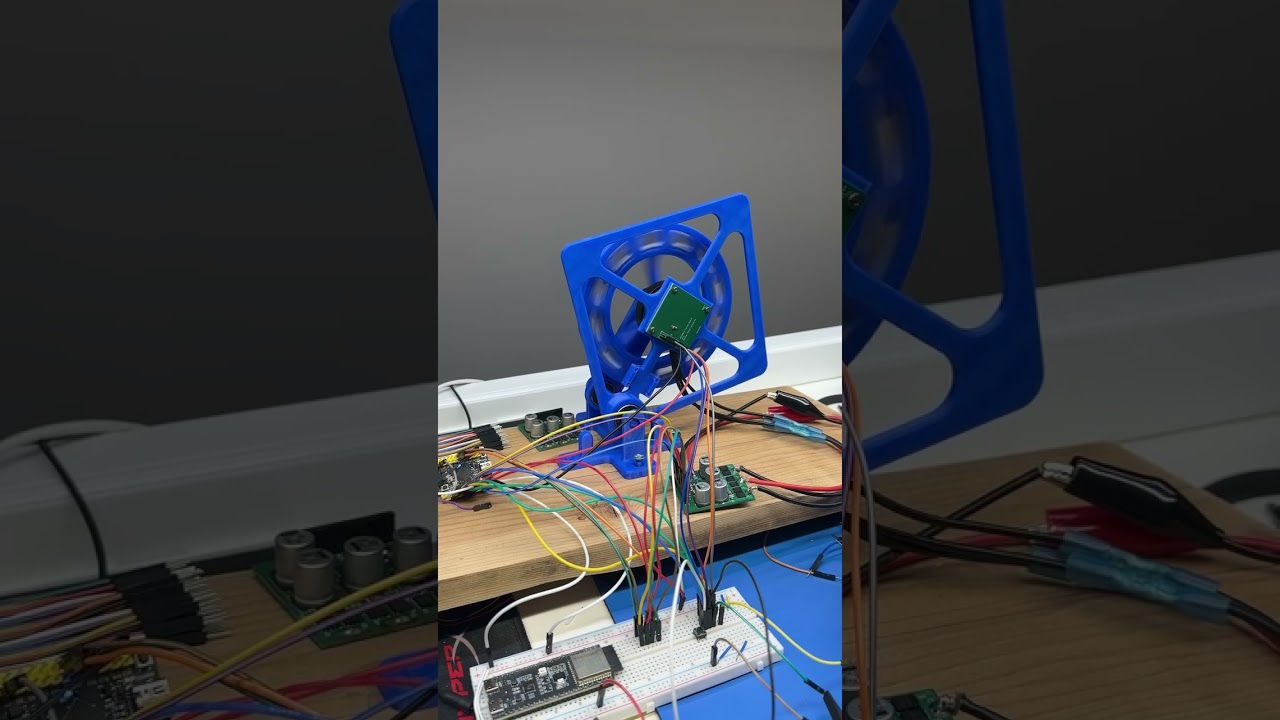
The apparatus doesn't have its IMU set up right now, this is just FOC testing. Limits are 0.7V and 8A. Driver board is theoretically capable of 12A steady or possibly bursts of up to 16A. Some destructive testing may be in our future but first I want to get this axis balancing. And maybe move the apparatus further from my computer.
very nice. Any interesting control theory you're using?
Just LQR !
🙂
It really works now

Added the trim factor, upped the wheel speed penalty. Motor settles to a zero point, although I think my bias rejection alpha parameter is too high now and leads to too long of a settling time. Wheel is also capable of rejecting small disturbances although with the RPM limit I have installed the rejection limit is quite small.
LQR seems a lot better about rejecting disturbances than PID
