#archived-shaders
1 messages · Page 248 of 1
Remember that macros basically paste in code, its not a function.
Your example is trivial, so my answer may be too (in other words, in the real world the answer may not work)...
But if you want to manually unroll that you'd just do:
float f = f1;
float f = f2;
float f = f3;```
So IDK what your real use-case is.Yeah. My real world use case was a bit more complicated to unroll manually like that.
But I guess, not too more complicated
Just thought I could use a little trick to make the code a bit prettier.
@kind juniperis correct, macros aren't a function, but that doesn't mean that your solution cannot be a function. Or even a function-like macro.
So instead of doing that extra-clever macro that would require unrolling, you could either call a real function or use a macro as:
f = DoWhatever(f1);
...```I guess try it. Use an [unroll] attribute and see if the macro substitution works out.
But...IMO...if I had to maintain your code, and there were only 4 iterations and not 100 of them, I'd be sending out some negative energy...for making me have to think about that macro rather than typing the line 3 more times (or better yet cut and paste + editing).
Hahah. True that. Guess I'll avoid the complication and save myself some time(there was indeed 4 elements only).
Is it possible to use two shaders on the same object at the same time?
Well yes if the object has two materials.
I want it to affect the same material, cause I already made a curved world shader, and I want some kind of distortion on the object too so I wasn't sure if I can do it
Doesn't seem that hard, thanks for the answer!
Tried to make some quad to billboard styilzed bushes but there seems to be a transparency sorting issue?
How can i fix it?


Transparency often presents a problem when I’m working in Unity3D. The methods used for rendering objects in the right order doesn’t work well with transparency, so I often need a work-…
HDRP doesn't seem to have an option for transparency sort mode

Guys what type of shaders should I create that's good for beginners?
I'm following this tutorial but I can't make my effect show up in the Game view? I've followed everything this tutorial was doing, unless there's one step there that I missed, can't figure out what it could be though

Now you can easily add a Retro feeling to your game with this cool Shader Graph and Render Feature combination. With a few Post-Processing effects on top and that's it you got yourself a CRT / Old TV feeling. Enjoy!
Pixel Art Tutorial: https://youtu.be/JZDlCuIpq9I
Cyan Blit Render Feature: https://github.com/Cyanilux/URP_BlitRenderFeature
✦Rab...
shader's complete, but the result is just...
well the effect just doesn't show up

cyan isn't online now but if they are here hope you can help!
Settings if you're wondering


I figured it out, I had to change stuff in the project settings, wasn't anything to do with the shaders, my bad, I didn't know about any of that
so I had to change stuff on my camera afterwards
Was it to enable the scene color option in the settings? He used the scene color node in the tut, but the option has to be enabled otherwise IIRC it just returns a grey for everything. Or maybe black.
HDRP? Oh....Didn't realize that, sorry.
:ssss
No I fixed it myself, was something to do with URP and adding the renderer I wanted to use for this scene onto the pipeline asset
I only figured that out after noticing my renderer was not showing up on the camera after looking for the issue
I want to pick your guys' brains for the single most impressive shader/material (wizardry) I've seen, it's not significant in the slightest, mostly as decoration for the theme of the place
I'ver seen it used in certain tutorials, so I'm sure it's possible, but I never saw the code and I'm wondering if anyone knows how to fire a raycast in a shader.
so in Luigi's Mansion 3, you're in a mostly blank room with sand and a pyramid in the center, but the sand itself is incredibly impressive, you can walk on it, suck up the sand, blow your vacuum on the sand (this guy doesn't show it I don't think), how do you even perform this wizardry?

Check out our Luigi's Mansion 3 Floor 10 Walkthrough tutorial to see the 100% 10F Tomb Suites guide, including how to get out of the Pyramid.
You’ve got to love Floor 10, Tomb Suites. Nintendo has a long tradition of sand-based levels and they manage to take all of that legacy and mix it with a good amount of something new to deliver a great ne...
It's like a simple snowtracks shader, but 3 times more complex
I would really love to know your guys' takes on this cos I have a few thoughts but really don't know how you would ever do this lol
the most impressive part of all of this is this is running on a Switch
Well firstly, it is commonly done in shader based ray tracing/marching. There is a technique of uploading ALL triangle data (or SDF info) to the GPU in buffers so it has it all available at once. It is hella slow, and bulky, and impractical for real time data IF IF IF you want to know in the shader what object your ray has hit, like you'd know in C#.
HOWEVER, you can also do screen-space ray casting. In that, you use the depth buffer, and the camera and transforms and compute the world-space position of each pixel. You'd then know the position, color and depth of the nearest drawn pixel, along with any other things like normals, stencil information, or maybe motion vectors or anything else you managed to track in a special render texture tracked by all your shaders manually. For examples of this you may want to look into screen-space shadows, or maybe SS ambient occlusion.
Then there's ray-tracing in hardware on cards, for that you use an API, but I don't think you get per-object info in that either. I haven't really played with it, but I think it is more screen-space-ish than it is object-detail space.
:2 cents:
hmm, that may be too complicated for me but thank you for the information
Maybe I'm making it too complicated. What do you want to do with it?
set up a mirror by calculating based on camera angles and normals and stuff, to cast a ray and get the colour.
there may also be a better system for a mirror, that's just what I thought of
First off, that's good creative thinking. 🙂
The challenge with that is (and IDK how the raytraced API's in cards do this, so I'll ignore that and if you want to use ray traced hardware you'll have to go to the API docs to see) that mirrors can show the BACK SIDE of things that were never rendered from the camera's view. So if your camera is looking at the front of, say, a sofa...the mirror on the back wall is reflecting the BACK side of the sofa...that was never drawn.
So you'd need all the scene detail and materials to "draw" those objects in the mirror using a ray casting method. I think the APIs do that somehow. But like I said above I'm unsure how they pull all that off...they even do some off-screen stuff.
BUT there's good news! The common way to make a mirror is to use a second camera (lower res usually) and re-draw the scene from that camera's perspective. Yikes! Double the draw time for the scene unless you use a lower res image. But it can be done.
This is often done with "TV Screens/Monitors" showing the area you're in and showing you, from a different angle.
ok thank you, I considered the camera thing before, but I figured that a shader would be less expensive also because I'm already rendering the scene a whole bunch of times with portals, but I'll probably do that. Thank you!
@merry oakYou may also want to research using reflection probes, that's what they are all about.
They're basically another camera, drawing the scene in a lower res image. And they can be set to fire off at different intervals. You might find that the combination of a reflection probe and a reflective surface is all you need, no fancy shaders required.
Oh, alright I'll look into those thank you.
The thing with reflection probes is they draw a cube-map, so 6 camera shots, basically. But optimized for that. With a mirror, if that's all the reflection you want, all you need is one shot, not 6.
EDIT/ADDENDUM: the challenge for one camera might be getting the perspective/frustum correct for the mirror's view. The reflection probes hold the WHOLE scene view from each of the 6 angles with a camera at the probe's position, and then the reflection calcs in the regular scene's shaders take into account how the reflections map into that probe. BUT if you're doing portals, you may have encountered the perspective issue already and have a solution. You may even be able to create a custom frustum to auto-cull things that wouldn't be in the mirror's "view" while drawing it.
That makes sense.
Did Unity ever address not being able to access the extra 4 textures in a HDRP Terrain shader? I can access the first 4 using the Control0 reference but there was no way to access a Control1 for the other 4 a while back, wondering if they ever let you access that
How do I do it now but not in a shader cos for some reason I can't do that @meager pelican
This works, but when I blit it it doesn't wanna work


I did this second blit wrong but I fixed it
still same issue, nothing changes on the render texture
was following this video

A new tutorial series on how to create a snowtracks shader in CG language, within the Unity Engine.
You might want to make footprints in the sand, or snow. Or create a thick line of tire tracks, but also displace the terrain. With this tutorial you can do that, using tesselation. Learn step by step how to do it.
Created by Peter Olthof from Pee...
Alright so I have been following it for a bit now, I have some problems though, my brush is set to red and is a simple faded tip, but it fills my splatmap (I called it trail map in my case) and it’s blue?
I’ll post what that looks like later
Hello, I believe that my shader graph is bugged. I used to be able to open the Node selection menu, where I wanted to find the Custom Function node but I couldn't find it. and Suddently I am not longer able to open that node selection menu
I am using URP and the shader graph package is up to date
It could be a splatmap, but to me it looks more just terrain displacement, the same sort you use when editing terriains
Or possibly both in conjunction
It looks so good because the texture adapts to the deformation, and the deformation is controlled to avoid extreme changes in elevation
Sorry I'm a noob at shader graphs but I have no idea why this isn't working. Pressing view documentation just leads me to an missing page


what are you trying to view documentation for, what have you applied this material to, and how is it set up?
Was trying to view documentation on "Base Color", the material is supposedly for the skybox, and that's pretty much it.
how have you applied it to the skybox, and what does the material look like?
I applied it by dragging it onto the scene view. And this is what the material shows when I click it

dragging it onto the scene view? Is there an object in there it can be applied to?
I changed it to lerp and it works better in the preview but it's still just one plain color
No but it changes the skybox when I do that on other skybox materials
I went to check on lighting and it does changed to it

I'm not completely sure how the skybox shaders work, but I'm pretty sure they use UV coordinates, not geometry direction
I see thanks, I'll continue to test things
Before you go further just make sure that the sky you're looking at isn't just inverted
I checked but it's all still blue
Shader Graph: Is there a way to call into the regular lit shader as if it was a subgraph? I basically only want to use the Shader Graph to construct an emissive map for the default lighting
Use View Direction node in the Dir input of Sample Cubemap
The default direction is normal direction which won't work for skyboxes
@amber vector oh and another thing
Transparent and alpha clipping need to be disabled in graph settings for a skybox
Thank you! I'll try that out
Anyone encountered an issue where unity complains of not disposing of an allocated compute buffer when you allocate it both at edit time and runtime? In the editor I allocate in OnValidate, but I'm not sure where I should dispose of it? Presumably somewhere before domain reload? Do I need to subscribe to some kind of editor-only event?🤔
Exiting play mode also yields the warning, which is weird, since I have dispose called in OnDisable
Surely it's the OnValidate one both times if you're not handling that one
Where should I handle it? I need it to live until the domain reload.
Thank you so much! I inverted it after what you told me to add and it's shown as intended now
Alright. Thanks I'll try it out.
I thought it was a common issue, since wanting to see the compute buffer data rendering at editor time seems like a common thing, but I guess I'm wrong...🤔
Hmmm... Doesn't seem to work in a MonoBehaviour
Weirdly enough, releasing the buffer in OnDisable doesn't seem to work either for some reason.🤔

Hello can someone please help me confirm of this is soemthing im doing wrong or is indeed a bug
have you checked that you're not allocating many buffers?
Not sure how to check that. I'm releasing the buffer if it's not null before allocating a new one. I imagine that should prevent from leaking previous buffers?
Not sure if it's the correction solution either. I feel like I should be reusing the same buffer as long as I can..?
log when you create them and make sure there's only the logs you expect
Hmmm... I guess it is the OnValidate. it seems to be called after OnDisable, but before Domain reload(presumably) sometimes.
I hate OnValidate and barely use it as it gets called all the damn time
pretty annoying. The solution I came up with is [ExecuteAlways] attribute. That seems to call the OnEnable/Disable methods at proper times, so I can have my shader render properly both in the editor and runtime. And the allocation warning is gone.
Did Unity ever address not being able to access the extra 4 textures in a HDRP Terrain shader? I can access the first 4 using the Control0 reference but there was no way to access a Control1 for the other 4 a while back, wondering if they ever let you access that
Is there a list of Blender node equivalents for Unity?
not as far as i know, but id love a list of anyone knows. i think you just need to know what the node does and find a node that does the same thing. like if i remember correcely the blender ramp node is basically a very convenient step() node
so they are often not named anything similar which kinda sucks
ah, i would had never guessed ramp was called step
indeed, thats what makes it a hasle
i had the opposite problem at some point and its painful trying to figure it out
though one thing i did figure out is that most of the time blender is simplified and in unity it would be more complex since blender does a lot more automatically
I didn't think of terrain haha, only because the vacuum also affects the sand
Ok here's what that looks like, I just painted with my mouse, but it just looks like this

This is what my draw shader looks like

This is what my snowtracks shader looks like (the bottom left is my splatmap (trail map is what I'm calling it) and it's only blue because it clears on start

This is what my script looks like

so from all of this I don't know which part is wrong
Is there a way to change the full rotation to not 6.285? I set it to a slider value because it lags/glitches when set to time

I dont understand your question ^^
Rotation value required to make 1 full rotation is 6.285, is there a way to change that to maybe 360 so it's easier to set up?
And also so it's more accurate since the 6.285 isn't perfectly 1 full rotation XD
I see, thanks
and that is Tau, the full rotation around a circle
or 2 PI
If you just switched your unit to degrees you would have what you wanted
Help, shader graph aint building

says theres a syntax eror
but how can there be a syntax error if i havent even touched the script yet?
I'm trying to combine meshes to reduce draw calls. I need to make sure the new vertex positions end up in parent localspace because I proceed to do other calculations with the mesh using predefined boundaries meaning worldspace coordinates will almost always be out of range. Each CombineInstance accepts a transformation matrix so I pass local -> world. However if I then multiply that matrix with the parent's transform.worldToLocalMatrix I get weird results so I ended up transforming the position after the mesh has been combined. Does anyone know how I can avoid this?
        var fragments = GetComponentsInChildren<Fragment>();
        var combine = new CombineInstance[fragments.Length];
        var i = 0;

        foreach (Fragment frag in fragments)
        {
            var childMesh = frag.GetComponent<MeshFilter>();
            combine[i].mesh = childMesh.sharedMesh;
            combine[i].transform = frag.transform.localToWorldMatrix; // DOESN'T WORK (* transform.worldToLocalMatrix)
            i++;
        }

        var mesh = gameObject.GetComponent<MeshFilter>().mesh;
        mesh.CombineMeshes(combine);

        mesh.vertices = mesh.vertices.Select(v => transform.InverseTransformPoint(v)).ToArray(); // DOES WORK
Could someone help me with this
Anyone knows if there's a special function for that formula?
floor(a * b) / b
so if a is in the range of 0-1 and b is something like 4, you'll get values 0, 0.25, 0.5, 075 and 1 for different ranges of a.
Also, does anyone know if there's a callback/event I can hook to on after shader compilation to bind the buffers again? Unity seems to unbind everything from the shader.
Can only make it work if I use a texture reference

Haven't been following convo completely but I'd make sure the Blit call specifies a pass index param, set to 0. (Otherwise it'll render all passes as it defaults to -1)
In your script. Try changing it to, Graphics.Blit(temp, trailMap, drawMaterial, 0)
That works, I never saw that in any of the tutorials/github projects I looked up, but it clears itself every time it's blitted to
I mean it doesn't add to it, it just has the brush size and strength in that position
Hello, I believe that my shader graph is bugged. I used to be able to open the Node selection menu, where I wanted to find the Custom Function node but I couldn't find it. and Suddently I am not longer able to open that node selection menu
Can sample texture2d _MainTex in brush shader, then combine the result with that. Probably using a lerp.
This is frustrating

sorry if I described it bad, this is what I meant
My brush shader graph doesn't have a texture on it
You need to add it. The reference _MainTex gives you the source texture in the blit call (temp). Look at the tutorial and you'll see their brush shader basically returns saturate(mainTexSample + brush)
I don't know how I missed that honestly
Not sure how to fix that. Have you tried restarting Unity? or maybe a different project? or different unity version?
so would the splatmap just be passed as the alpha?
Hello, thank you for responding. I have tried creatibg a new project, restarting unity, my system, using HDRP instead of UDP. I should also note that my ability to place nodes before was on the VFX shader graph not the regular shader graph
Ihave also tried to "recompile all" and deletin my libraries folder to force it to compile it again
Can you maybe record a video or a screenshot of the issue? Because it's not completely clear what it is.
I'm not sure how to apply what is on the shader to my shader graph like the alpha
The ones I selected are the new nodes I added, but it still does not work unfortunately @regal stag

reminder I'm new to shaders so if I've done something wrong my bad
You can see in the tutorial that they add up color to the sampled texture color

col + drawcol
So you just need to sample a texture in the shader graph and add it's color to whatever you get from your brush
Need to set the texture from c# of course
I shall however It will take a while Im afraid. But ill try to send one as soon as I can. Sorry
those are the ones I added, that should be right I think
Ah, yeah, that should be okay.
but it's not?
What happens now?
Same thing as in that gif I posted earlier
Might want to share the C# part as well then
Did you set the property reference to _MainTex? (Under node settings tab while texture is selected)

Probably not. The point is that you need to feed the camera render texture into it if I get it right.
Not the camera.
But the results of the rendering of the shader. It's kinda like a recursion I think.
Ideally no, as even if you set the texture to your trail render texture, that's the target you are blitting into. The whole point of the "temp" target is to avoid issues with reading/writing to the same target.
Use _MainTex instead. Unity will already pass the texture into that property when using Blit.
I know Unity has some like magic variables like _MainTex just didn't think I had to use them here
It's only important when using Blit and SpriteRenderer iirc. Maybe UI Image too
it works now which I'm happy about, but I don't know why _MainTex just works like that, seems confusing to me, even if I know Unity calls these magic variables when I use those functions
don't know why" _TrailMap" wouldn't just work
Couldn't you use just any arbitrary texture names instead? 🤔
That's what I mean
It might, but you arent doing anything to set that property referemce. Unless you exposed it to the material.
If you set them in C# I mean?
how would I do that
Can use Shader.SetGlobalTexture or material.SetTexture, depending on if it's exposed or not
I accidentally took out legacy shaders from always include in build and now my ui looks pink only in build
anyway to tell which ones I need?
I'm on urp if that matters
so if I set SetTexture to _TrailMap on the draw material and the drawshader texture is named the same, it would work?
Maybe start a new project to see what the list defaults to.
Or revert it by deleting the file (in the ProjectSettings folder). But would need to reassign pipeline asset and maybe other stuff then
ah it was the legacy shader/transparency
anyone got any resource i can read to understand more of how to write macros?
i checked out the MS documentation though there arent any really great examples there
Should do, with material.SetTexture("_TrailMap", temp); and _TrailMap in shadergraph property Reference field. Also with Exposed ticked.
If exposed was unticked could use Shader.SetGlobalTexture instead.
I think Graphics.Blit is doing something similar behind the scenes, just with _MainTex
Shaders hurt my head, I remember doing this same thing in like 2018-2019 for one thing, I understand why I never went back to it until now

It's a little rough to say the least.
Shader Graph did not exist back then
this was uploaded in 2020, but I recall making this like in 2018-2019
It's almost the same as the C macros, so I guess learning about those could help.
^ Could also maybe check UnityCG.cginc or SRP ShaderLibrary files for examples.
I just made those changes, it didn't work
never mind, I just fixed it, I added it after assigning temp, I was assigning it to start by accident
it works now how I want to even if I don't completely understand it, but I'm happy with the result, I have to just make some changes with my brush

ok im attempting to make some macros in a cginc file but i keep getting this
there is literally nothing in there yet
i dont really know what this error means
Anyone know any good tips for cutting down shader variant compilation time?
Unity is doing like 20m
I mean that's exactly the problem. That error is basically saying "expected to see a shader program here, but instead saw the end of the file"
ah, but what if i use it only for macros?
it seems like its working, but i dont like having that error there
not sure, I don't know enough about shader code to help with that
hello everybody! Does anyone know how to fix this error that pops up in my project when I try to run it? : Shader UI/Default shader is not supported on this GPU (none of subshaders/fallbacks are suitable)
how would i go about exposing the fragment variables in materials that are using a custom shader graph?

i think there's a switch somewhere i have neglected to flip
(URP if that makes a difference)
Do i need to make a custom exposed variable for each of these? (was hoping i could expose these directly)

shows up with these empty fields for some reason...
You need to manually create and connect the properties
yea i managed to conclude that, but thanks!
now im stuck trying to figure out how to disable Z dept testing in a TMPro shader (or a variant i can create)
so that it renders on top for UI purposes
ah wonderful
they have a built in one
Distance Field Overlay it's called


@ancient arrow You're not using alpha clipping or transparency so it can't be anything but a square
?
well, how do i fix it
by using alpha clipping or transparency, along with alpha of the sampled texture


This happens with textures that use bilinear filtering instead of none/point
k right, forgot
well
fixed the second problem
now i need to get rid of the grey color
any ideas?
Does anyone know how to make a fake backface in shadergraph? Not actual transparency, but display on the surfaces "depth" of the opposite side of the cube

Sorta like a fake window or fake interior shader? Ill try googling those
does anybody know how could i reproduce this shader

the outline
just realized that unity have something similiar
I'd imagine that you need to enable rendering back faces and render them with decreased color intensity based on the depth. No clue how to do that, but it's probably gonna include messing with the depth texture(In fact it might require another render pass). Would love to know the solution if you find one.
Ill keep you posted if I manage anything

https://www.youtube.com/watch?v=rC4BHR-Cx0s I followed this person's tutorial
Nice. Did you manage to get the effect that you mentioned in the beginning?
Yeah, the above gif you see there, the cube is not transparent nor is it turned inside out, its just a default unity cube
but it looks like you can see the 'backfaces' of it
I mean, with the deeper parts of the cube getting darker
Alright. I'd love to see the final version. So keep it up. 😄
I got another effect I want to pick your guys' brains about
TheGamer
The developers have gone as far as to implement a mechanic where enemies killed in bodies of water will have their blood react realistically.
how would you achieve this?
Sorry if I ask too much about re-creating shaders, I just like to see this kind of detail, and I wanna hear how you guys would achieve this so I could learn from it
why it wont show me

the distance node is great for effects that need to be spherical but is there an easy way to get a cubic volume instead of a spherical one in shadergrapgh?
Hey I was following Unity’s flag waver shader tutorial but got this

See Box example here : https://iquilezles.org/articles/distfunctions/
(they are glsl so may need rewriting slightly, mostly vec->float)
Articles on computer graphics, math and art
Probably should be using the G output on the Split (since the whole calculation goes into the G on the Combine later, the purpose is to alter the value not change the axis)
Not reequired, but I'd also add a Multiply between that G output and Add node so you can adjust the frequency of the sine wave.
G output to where?
Can someone help me make a toon shader in URP shadergraph?
Both the shading and the outline
The Add node, currently you have the B axis connected
This is the result
Then may need to compare the graph to the tutorial. It's difficult for me to debug right now, maybe someone else can jump in.
I would also assume they use a plane mesh (subdivided quad) rather than a cube too as this doesn't have enough vertices to displace.
I compared mine to the tutorial a few times and everything was the same, and okay I will check the mesh thing later. Thanks
You are amazing, thank you. I changed it to a plane mesh and it worked
With G not connected to Add by the way
When G is connected it does less of a wave
Anyone knows how can I rewrite this so that the shader compiler does not throw an error?
    uint texIndexL = lastIndex / 4;
    uint channelIndexL = lastIndex % 4;

    float4 tWeight1 = 0;
    if( texIndexL == 0)
        tWeight1[channelIndexL] = weight1;
The error is
array reference cannot be used as an l-value; not natively addressable at kernel CSMain
it's because I try to assign to a float4 component via an index. I'd write it manually, but I have 7 more float4's like that...
I've got a shader that isnt meant for UI stuff that inverts the colors behind it and that part works
but I need some way to get it to work for sprites and text without it applying to every part including the transparent bits https://cdn.discordapp.com/attachments/502171135350407168/998599789367267368/unknown.png

Is this supposed to be legal syntax? I haven't seen it anywhere else... You could make a helper function that takes an index 0-3 and then assigns x, y, z, w with if statements
It is. But sadly it seems like the shader does not like when I try to assign a value like that.
Yeah, I ended up creating several functions.
you were indexing with channelIndexL, but does indexing with the variable defined in the for statement work?
It does, but it yields a similar warning(at least when I tried before in a different place). The warning can be cleared by unrolling the loop though.
But in this case, I'm not sure how I can use a loop
Not an expert, but It seems like the GPU expects a constant value to use for indexing when it goes to unroll
It's able to unroll if the number of iterations can be inferred at compilation time it seems.
That makes sense if the work is being divided across multiple threads that do not share state
https://blog.playstation.com/2021/01/12/how-stunning-visual-effects-bring-ghost-of-tsushima-to-life/

A deep dive into the wind, weather, and interactive particles that make Jin’s journey come alive.
there's a nice overview here, maybe can give you some ideas
https://cdn-animation.artstation.com/p/video_sources/000/388/798/square.mp4
How was this effect achieved? He links a shadergrapgh but when you make that graph, every face of the cube shows the cubemap from the same angle, instead of from the angle relative to the cube itself (as pictured second.


Correct
Otherwise youd see massive fps drop with massive planes. All the triangles are clamped at the screen when rasterizing
Its called inverted mesh pretty sure
k, question, is it better to write shaders with code instead of using shader graph
its not, the effect there specifically is some cube map shader wizardry
Graphs tends to be easier for beginners as they do some of the setup for you and don't need to worry about code syntax. Personally I also find working with graphs quicker and more readable, but that'll be different per person.
But shadergraph does lack some features, e.g. Stencil operations (though can edit generated code or use overrides on RenderObjects feature in URP). No support for UI yet really. Probably more that I'm forgetting.
Well written code can likely also perform better than a graph.
I know an inverted mesh can have that appearance but I can't use one in this specific circumstance
Hey if I wanted to make my sprite 1 specific color while maintaining transparent pixels (like not tint the pixel, set it) what should I do?
In terms of shader graph?
Use a Color property in the Base Color output. Connect texture sample A output to Alpha
Will that not make the whole quad that color or nah?
Not with the alpha connected and graph set to Transparent (or using alpha clipping)
mmm

Can you show the graph

Yes use a Sample Texture 2D node and connect its A output to Alpha
for making sure it uses the texture from something like a SpriteRenderer
do I create a Texture2D property with a reference _MainTex
the answer is yes
working
ty
oh wait, hmm I still want the color field in sprite renderers to allow me to tint this whited out sprite
does anyone know how to disable LOD only in the editor view
Multiply the colour property with the Vertex Color node
well, time to learn a hlsl
or whatever unity uses for shader language
Yea, HLSL + ShaderLab. Bear in mind that the includes/functions varies for each pipeline. There's a good amount of code tutorials for Built-in RP. A few for URP (including one of my own, mentioned in pinned messages). Don't know about HDRP, I think using graphs are recommended there.
ShaderLab?
Sorry, on mobile. Can't type that fast
dw, i have a lot of time
Yea it's a syntax unity uses for the shader file to separate exposed properties, subshaders (to support multiple platforms), and passes (which then contain hlsl). If you google for shader code tutorials it'll probably be the first thing you'll learn.
is it hard to learn it?
im just getting confused with all this math operations and pixel rendering and so on
i just got used to work with "big" things, idk how to say that properly
If you're confused about it in graphs it wont really be any easier in code
Unless you are more used to coding I guess
coding is better for me ig
Visual scriptring or smth similiar to it, just confuses me
with all these node connections and so on
Ah okay
k so
ill start my learning process
from making a greyscale shader
Which one do i use for the sprite

Unlit?
Depends if you want lights to affect it probably. Might also be interested in the shaders unity provides (for Built-in pipeline) : https://github.com/TwoTailsGames/Unity-Built-in-Shaders/tree/master/DefaultResourcesExtra
Might be able to use the Sprites-Default as a sort of template/example.

GitHub
Unity Built in Shaders. Contribute to TwoTailsGames/Unity-Built-in-Shaders development by creating an account on GitHub.
Oh I missed that, I was looking into just that one effect because it was so well done
why its isnt working


what im doing wrong
it just makes my image go completely white
but in theory it should be just the same image
@regal stag oh my god, i actually managed to write own grayscale shader

Hello! I need some help translating this Amplify shader into default shader graph nodes:

here's what the effect looks like:
https://twitter.com/i/status/1047006623330373632

I'm sure this is trivial to smarter people, but I've struggling for an eternity trying to figure out how to have screenspace mapping locked to an object's world position. Thanks to @wingcutangel for the tip!
Likes
223
here's my old setup i was using, but it conforms to the objects normals and stretches at the ends of the screen:


I tried this approach as well and it works ok, but rotation and distance of the camera causes the texture to jump and slide around:
https://cdn.discordapp.com/attachments/497874081329184799/839185006428684298/StabilisedScreenPosition.png

how do I access the render result of the previous pass?
grabpass nevermind
How can I create a shader for what would create a seemingly distant planet which is a sphere that gets the sunlight direction and renders a solo outline using the fresnel effect along with some normal maps and a noise generators and also isn’t linked to the skybox

Need to start from creating a custom shader. You can use the fresnel effect and multiply it by some value based on the light direction and normal(vertex) dot product + normals(from normal map). It will need to be transparent to blend with the skybox probably. Can't say more than that without trying it myself...
quite simple actually
in theory, (as said above) you just need to assign normal (dot) lightDir into alpha, although seems that the alpha need to be clamped to 0 since it result in negative value
c.a = clamp(dot(s.Normal, lightDir), 0, 1);

That said, I think its actually overkill where a sprite with some custom masking could do the job too
@brave pivot The default transparent shader (particle shader in BiRP) with additive blending does pretty much that
I tried making my own outline shader, but this weird thing happens from some angles. It shouldn't be black, it should just have a normal black outline, like at the top

this is how I made it

would anyone know how to help me remove that artifact? Or otherwise, if anyone knows of a toon shading + outline tutorial video, it would be greatly appreciated
I want ot make the outline without making a bigger duplicate of the model, and making that black
What this method seems to do is take the surface normal, compare it to the view direction, and if they're close enough to orthogonal, it returns black, otherwise it returns white. So if you have a plane where the surface normal is uniform everywhere, it would return white with no outline, until you rotate it far enough and then it'd return black, again with no outline. If you have a smooth convex shape, it should usually work, as you're seeing, but any flat portion would act similar to the plane (as you're seeing).
Afaik, most toon/outline shaders create another mesh with the same vertices, shift it outwards (along the surface normals) a small amount, invert the normals, and paint it black. By shifting it outwards and then inverting the normals, they make the side in front invisible (since the normals are pointing away from you) but the back side is now visible, and a small bit of it extends around the object, creating an outline.
I know but all the tutorials do that manually, I don't want to manually copy + paste every outlined object
would you know how to make a proper toon shader?
or, if it works, I have a toon shader that I used originally, until I went to universal render pipeline
Hastebin is a free web-based pastebin service for storing and sharing text and code snippets with anyone. Get started now.
if there's a way to use that with URP, I would gladly just use it
you could try to do something where you calculate the curvature and the current angle between the normal and the view direction, then use that to estimate how close you are to the horizon of your object, and depending on that draw an outline or not
the thing is I've never done shaders before, and don't really know how to do any of that
oh ok
do you know of a good tutorial that would teach me how to properly use shader graph, and then I could do that?
ig you could take the derivative of the normal/view dir dot product with respect to screen space position, then divide the current normal/view dir dot product by the magnitude of the derivative vector, which should give the screen space distance after which it reaches zero (the horizon)
if that distance is less than a threshold value, draw outline, if not, draw object
make sure to account for if the derivative is zero (either add a small amount or branch to color it as the object color)
Brackeys has some tutorials making stuff with shader graph, though messing around in it is pretty good to learn
Btw you don't need to feed the position node into the vertex position output, it does that by default. You only need to feed something in if you want to change it
This is what I was thinking

(then in the branch, if true, it returns outline color, if false, it returns the main color)
Here it is on a planet

And on a sphere, capsule, cylinder, and tree respectively. It doesn't work if there's a sudden change in curvature so it doesn't work at the ends of the cylinder or bottom of the tree.

@meager portal
Oh thx
Since you're using URP, you could use a customrendererfeature to draw a second time specific objects as black pushed backface to make the outline
Maybe also look at how it is done here : https://github.com/UnityTechnologies/open-project-1?utm_source=YouTube&utm_medium=social&utm_campaign=evangelism_global_generalpromo_2020-09-21_open-projects-01-repository

GitHub
Unity Open Project #1: Chop Chop. Contribute to UnityTechnologies/open-project-1 development by creating an account on GitHub.
Oh thxI tried using that, sownloading the source code and using their shader
Howver it didnt show any of the values like body color and stuff
thank you so much that worked
np :)
one more thing, is there a simple way to make a toon shader, in the sense that all the shading is split into 3 or so solid colors across the body?
Yes, just multiply by the number of levels you want, round it, then divide by the number of levels again
multiply the main color? that didn't work for me


B input of power is negative ?

Ah sorry, I've didn't pay attention, it's the A input that is partily negative in the black area I think ?
How can I figure that out? Idk tbh
Im trying to make a planet shader but I cant figure out one thing which is how do I make the fall off to transparent more like a gradient rather than a hard edge

This is more like what I'm going for

Don't use alpha clip
Also, you have NaN value at the power node because there is negative values in the A input
( this is why it's showing majenta )
But how can I fix it with out messing up the normal map
For the transparency : disable alpha-clip and change the surface type to transparent
For the power node : add a saturate node before the A input
ok that fixed it
Lastly how can I make the sides of the light come to a point

or should it not matter
You need to fix how you're doing the effect
Connect directly the sample normal node in the A input of the dot product, and set it into world space.
it is
No, not when I look at your screenshot
Can you show the current graph/result ?

Not what I said at all 😅

theres only tangent and object
Ah, crap
Then keep tangent, and in between the sample and doc product, add a "transform" node:
- from tangent
- to world
- type direction

Is it giving better results in the scene ?
yes
but the directional lighting is way over exposing it
how can I change it just for the sphere

You could just change the base color to be darker
is there anything else I could do to make it look more distant

I've read about % operator in HLSL and msdn tells that result of 1f % 2f is 0.5. This is strange for me. I'm trying to fix my shader code which uses %
float2 TilingAndOffset(float2 UV, float2 Tiling, float2 Offset, float4 UVBound)
{
  return TilingAndOffset(UV, Tiling, Offset) % UVBound.zw + UVBound.xy;
}
Make it very small ? 😅
Are you sure about that ?
I think 1%2 should be = 1 🤔
yes, me too
What are UVBound here ? minXY & Max XY ?
yes
i just passing (1,1, 0,0) Tiling and Offset values. So with my formula there should be no value change at all
Well, %0 seems quite dangerous
UVBound.zw by default is 1,1
i just passing (1,1, 0,0)
it is Tiling and Offset, i then gets bound based on it
float4 GetUVBounds(float4 TexST)
{
                float2 rightBound = TexST.zw + TexST.xy;
                return float4(TexST.z, TexST.w, rightBound.x, rightBound.y);
}
But anyway, %1 will change your values, removing all integer part of the coordinates
of course, but it is ok, because we need to UV be inside [0,1]
I mean more like this

Reduce the alpha globally
Multiply the alpha by a value between 0 and 1
That just changes how much edge light is shown
Or am I not supposed to do it in the shader graph
Then I "guess" that you need to change your code to this :
float2 TilingAndOffset(float2 UV, float2 Tiling, float2 Offset, float4 UVBound)
{
  return ( TilingAndOffset(UV, Tiling, Offset) - UVBound.xy ) / ( UVBound.zw - UVBound.xy);
}
?
How did you connect this ?

it works, but why? and what i did wrong? 🙂
Well, yes, reducing the value here will make the effect more faded, isn't this what you want ?
From my understanding, you wanted to tile+offset the original UVs, then remap this into the 0-1 range from the min/max values.
This is what the code I showed does
Well yes but I also want to reduce the alpha of the entire sphere so it would look more faded into the sky
{
  return (x-min) / (max-min);
}
Isn't it doing this ?
If strength = 0 the effect is fully invisible ?
I like where the edge light is currently I just want to be able to see through to the skybox while still seeing the edge light
Ah.
Well, this is a bummer, as the skybox is displayed at a "virtually infinite" distance, so behind the planet, while in reality it is in front

I have sprite on atlas. So firstly i want to pass something called MainTexSTOnAtlas to get proper UV. But then i want to Tiling and Offset this resulting rect. But it already not in 0,0,1,1 rect but in some arbitratry rect. So I want to pass extra MainTexST and do Tiling and Offset inside bounds of resulting rect from previous step. Remaping works in editor, because sprite refer to it's original texture and not to atlas texure, but in playmode as a result i see whole atlas texture being rendered.
You could try some trickery, like settings the fade mode to additive
how can I do that?
It's in the graph settings
- Take UVs
- Remap to 0-1 using the sprite rect value
- Apply your additional tiling and offset
- frac the value to have them repeat in the 0-1 range
- remap again to the sprite rect
Oh ?
"frac the value to have them repeat in the 0-1 range" this is exactly what i'm trying to do but a bit in different order. I just try frac the value to have them repeat in the range of sprite rect's UV which i called in shader "UVBounds"
So to repeat value a want to get it's remainder and add it to min value. I'm not sure is this mathematically right
But frac or modulo would always make it repeat in a 0-x range, so you will miss the minimum part of the sprite rectangle.
That's why I said to remap to 0-1 first
It makes it so you are working in the "sprite rectangle space"
I'm not clearly understand sequence of math actions here though
It should turn the allowed colors into a series of steps, what issue did you get?
- Take UVs
- Remap to 0-1 using the sprite rect value UVs are now in "sprite space"
- Apply your additional tiling and offset
- frac the value to have them repeat in the 0-1 range
- remap again to the sprite rect UVs are transformed back into the sprite atlas
So for example we have 0.5 0.5 UV coords and some 0.5, 0.5, 1, 1 sprite rect
- Remap 0.5 0.5 to sprite rect will give us 0.75 0.75 right in the middle of sprite rect
- Apply tiling and offset. we will get some value which now can land somewhere. For example i want to offset it by 0, 1.5, so result uv will be 0.75 2.25
- frac it inside 0-1 range will give us 0.75 0.25 which is already outside of sprite rect
- and then we want to take it back to sprite rect space by remaping it again. Which will give us 0.875 0.625 UV, but offset X was 0
My first step is "remap to 0-1 range using the sprite rect"
So, remap the 0.5,0.5 to 0,0
oh ok, i think i've got it
Hello, does someone know how to get depth buffer of specific camera in shader? Similar to how you can get main camera's depth by using _CameraDepthTexture. I'm working on a game with prerendered backgrounds and i need to get depth of my reflection camera(used for planar reflections) to be able to discard parts of reflection behind prerendered objects
Or maybe i need to write my prerendered depth to reflection camera before it draws other objects so they can be automatically occluded. I'm using simple plane with shader outputting depth with SV_Depth for main camera and dont want to do same for reflection camera because it's created at runtime
Basically i don't know how to better do it. Draw fullscreen quad with sv_depth shader to my reflection camera or get depth of reflection camera and then discard pixels in shader by comparing with prerendered depth
Or maybe there is better ways...
is there any equivalent to GetAdditionalLightsCount() in built in RP?
Probably not, as built-in uses multiple additive passes (ForwardAdd iirc) for additional lights rather than a loop.
so instead i guess i could pass it in by hand with a script or something
So as i can understand with 0.75, 0.75, 1, 1 rect and 0.5, 0.5 uv we will get -1, - 1 and this mean "where" current UV relatively to sprite atlas rect. Second step brings no questions. But how to repeat value in 3rd step? I mean frac will give us fractional part of a value, so in case of 1 we will get 0. + how negative values should be handled in this way? The final step should operate with [0,1] uv which relative to sprite rect and just remap it back to actual values.


Try plugging something in the uv channel. Like object position.
Maybe...
I mean, you can do custom lighting in BRP, and pass in an array/buffer of light data and use a loop in various stages, but the engine is really designed to pass lighting and do calcs in a certain way. So you'd have to "plug into" the various stages, such as using reflection probes and shadow maps in the right places. And regarding shadow maps, if you want then engine to generate shadow maps for you, you'd have to have "real" unity light objects that correspond to your array info, and perhaps mark them as "shadows only". And IDK what of 100 other things I didn't think of in this post.
But that's largely academic, since you could "just" use "real" lights in unity, custom light calcs if you need them, and let the engine do what it is designed to do...decide what lights are in range of your object, and call the lighting routines for them the "right way", and you conform to that.
If you simply need a list of lights for some reason, but aren't impacting colors, just pass the array. But if you want to impact colors, I'd conform to how the engine works and not fight it. Call me a conformist...
so you suggest i should switch to URP then?
I tried some things with the position in the uv but I didn't get the result I expected 😦
Not sure what to answer to that.🤷♂️
Thanks for trying to help. I will keep trying.
I mean, if you explain what you expect and how it did go, maybe we could help you better. But "didn't get the result I expect" doesn't explain a lot...
Tomorrow I'll try a few more things and I'll share the result here to make it clearer. But thanks anyway.
I am trying to implement a ocean shader made in built-in pipeline to HDRP. I don't know much about shader coding so I am trying to replicate it in shader graphs in HDRP from the code shader. But I am facing a lot of problems, can anyone please help me?
https://youtu.be/kGEqaX4Y4bQ
This is the shader I am trying to import to HDRP. The simulation part is working fine but the shader is the main problem. In HDRP the vertex displacement is still working, I can see it in wireframe mode but the surface shader is not working so it is looking pink. I am trying to replicate it in shader graph step by step and as a beginner I really need some help with this.

How does ocean waves simulation with Fast Fourier transform work?
Source code:
https://github.com/gasgiant/FFT-Ocean
Music:
https://soundcloud.com/igor_vaiman
Catlike Coding on Gerstner waves:
https://catlikecoding.com/unity/tutorials/flow/waves/
3Blue1Brown on Euler's formula:
https://www.youtube.com/watch?v=v0YEaeIClKY
3Blue1Brown on Four...
Well, what do you have so far?
I achieved this by multiplying the alpha with clamped worldPos.y

Did you do this in shader graph or with a custom script
I use code unfortunately, but iirc you can use world position node for that
How did u get the fall off at the horizon or is it just the light direction
by multiplying the alpha with clamped worldPos.y
do you know how I could implement it with the setup I have now or do you not mess with shader graph

Here's using another light direction

maybe in the last multiply node, you can insert position node, and multiply the y output with the last multiply output
yeah that worked thanks
Lastly how did you get that nice edge light to get mine to look like that I had to lose a lot of detail
and how did you get it to blend into the skybox so well?
Transparent material 🤔
Can you take a screenshot of how it looks for you?

You need some transparency in the visible part too
you need to clamp the world position y
what would the min and max be?
0 and 1
Ok I got it to look a lot better but how can I get rid of this sharp squared edge

Heres with the light changed a bit

I think it;s the fresnel node, I dont use fresnel btw
try to remove it

🤔 I think it has too steep gradient, try to lower the power values.
Or maybe plug the 1st multiply output directly into the one multiplying with position y instead
Could anyone help me with Ciconia Studio (double sided shader asset), I am trying to make my model double sided. I added the shader to the material, then the material to the mesh. But even though the material color is set to white, it is gray in some parts and white in others.

yep that fixed it

but after doing that the material greyed out a bit
compared to yours which is the look I'm trying to go for
nvmd
I just had to change the sun positioning
thx

What render pipeline are you using?
If it's birp, shader graph is not compatible with afaik.
universal
and what am i suppose to do now
Is it set up properly? If you add objects using urp materials/shaders to the scene, to they look pink?
Then it's not set up. Look up configuring your render pipeline in the docs.
ok
Depending on the unity version (2021.2+) you may be able to change the target to Built-in in the Graph Settings (tab in Graph Inspector window, toggled with button in top right of graph)
Rather than using a Fresnel effect to create the crescent shape, make the vector corresponding to the sun direction point away from the camera
So I am trying to get the vertex shader first. I need to understand the code to get the displacement correctly in shader graph. The wave generator script creates a plane with LOD geometry and assigns 3 materials using keywords, "CLOSE" "MID" and another for the rest.

and the vertex displacement is working even in HDRP but rest is broken. So I need to make it in shader graph, I tried to modify HDRP lit shader code generated from a shader graph but that is too big and complicated for me.

here is the shader code.
My problem is
- How do I multi compile in shader graph using MID CLOSE keywords?
- I need to understand the vertex shader code properly to replicate it.
I tried using enum keyword but I dont know what to use the "reference".
Try making it work without the LOD first.
okk I tried. here's what I got.
Were?
wait sending pictures


I am not entirely sure I used right nodes.
you can see the displacement in the distance kinda looks like the original.
the "void vert{}" is what I am trying to get

I think the UV part is okay?

this is "worldUV" part. but what does o.worldUV = worldUV.xy translate to in shader graph?
o is output. It's a struct that moves the data to the fragment shader
oh I see. So it is for the fragment shader part.
now what does v.vertex in this line?

v is the input data of the mesh, so I'd assume it's the vertex position in object space
maybe in clip space.🤔 Not entirely sure
and unity_ObjectToWorld?
Btw, the fact that it's pink probably means that you divide by 0 somewhere. Or that you're on a render pipeline that's not compatible with shader graph
transforms the position from object space to world space

yes like I said, this code that I am showing is for built-in RP. I am trying to port it in HDRP.
it's possible there's a division by a property and that property hasn't been set to be non-zero by default
I mean, I only use one node and route it anyway but was just wondering, if you use multiple of these nodes is shader graph declaring each of them using extra code? or does it use the function once and the nodes just act like pointers?
Basically, does SG use extra unnecessary code when you use more than one of the same node?

Ah, Guess that's possible.
I would guess for stuff like the time node it has all of those and it just refers whatever you attach it to back to that variable rather than recreating everything from scratch
If you copy the same code twice I would guess it recreates it
Subgraphs, idk
I thought so at first but then o.viewVector = _WorldSpaceCameraPos.xyz - mul(unity_ObjectToWorld, v.vertex).xyz; what does this mean? in unity documentation it said Unity_objectToWorld is current model matrix.
It's the transformation matrix that does what I explained earlier
that says the view vector is equal to the vector going from the vertex to the camera
it gets the vertex position in world space, then subtracts it from the world space camera position
world space camera position is this node right?

yes the camera position node is in world space
iirc
though you could also take the depth and multiply by the normalized view direction
so the the highlighted line simply means this nodes right? the output of the subtract is the view vector. yes?

does this node do the same thing?

And what about using this directly ? https://docs.unity3d.com/Packages/com.unity.shadergraph@12.1/manual/View-Vector-Node.html

Well, the left one is the view vector, in whatever space you select, and other is a node to access the different transformations matrices of this objects
okk now what are these variables?

they are not properties, where are they getting their values from? they are only used in some calculations.
They're probably set from C#

No. That's just name.
*identifier. You can name them whatever you want
okk so I can use them in reference name right?
reference name?🤔

Yes
Ah, yeah
great
If you don't expose them in shadergraph they will act the same as in the shader code


I think so
No, add the position AFTER the transform node
When i'm using frac or % with UV in vertex shader sprite invisible in edit mode but completely fine rendered in play mode. But when using same instructions in fragment shader all goes well.
Should i handle UVs only in fragment shader?
@amber saffron so this?

yes
well still no luck 😦
the geometry is completely broken

this is how it should be

except the pink part ofc
I think I saw some issues in that last screenshot


It doesn't match the code
Divide the worldUV by LengthScale2, and use it to sample the texture, don't divide the result of the sample
I guess it's the same for the other samples
okk trying it
also I was trying to get the one of the cascades, there are 3 materials multi compiling. How do I get the keywords? there are 2 keywords "MID" "CLOSE" and using 3 materials.

You can use the keyword property
enum or boolean?
yaaayyy got the displacement right. OMG you guys are god. Now I have to figure out the keyword part and then the normals.

im following a shadergraph tutorial but the swizzle node in the tutorial and the swizzle node I have in unity are completely different, googling I cant find a reason why

I also dont have those colored bars, their interface in general is very different
Hum, looking at the code I think enum should be used
may be tutorial is using older version?
The swizzle node ideed changed, but you should still be able to set it up
For the red colored bars, this is a shadergraph option
I cant find shader graph in the package manager, where is that option?
@amber saffron okk so what do I use in the reference name? I just used material cause I didnt find anything. Is this important?

If you can edit and create shadergraph, you have it installed.
This is the settings I'm talking about : https://docs.unity3d.com/Packages/com.unity.shadergraph@13.1/manual/Color-Modes.html
It really is only a visual helper, and doesn't change the shader
Oh I see
the doccumentation for the swizzle node for the version of shadergraph I have says it should have mask
but mine doesnt

In shadergraph, the reference name is use as suffix of the option values for the keywords
So you'll end up with _MATERIAL_CLOSE and _MATERIAL_MID.
IDK if you can avoid this :/
hmm so if I keep the reference field empty?
Strange ...
You can still work around it, RGBA matches XYZW
I followed this tutorial node by node identically but my results are completely different to theirs, and the only thing I can find different is some of my nodes arent the same
if I start substituting nodes, I have no way to keep following this tutorial or get the same results
he doesnt post what version of unity or shader graph he's using
I'm not talking about substitution nodes, just using the older node visual to achieve the same thing.
If the mask input is "yz", you can make the same with the old swizzle and use:
- output r : input g
- output g : input b
You could even do this manually by using split and append nodes
I see
@amber saffron so If do this, the keywords should be "_MID" "_CLOSE" right? do I have to change it in the other script that is enabling these keywords? or "MID" counts the same as "_MID"

They might end up beeing "__MID" for example.
The best is probably to look at the generated shader code 🙂
For example, if your reference name is MYENUM and the desired entry is OPTION1, then you would call Material.EnableKeyword("MYENUM_OPTION1")
hmm then I think it is better to change them in the script and rename them there
so If I do this and use "M" in the reference field it should be working

https://cdn.discordapp.com/attachments/996979168304697384/999336344713175121/unknown.png
https://cdn.discordapp.com/attachments/996979168304697384/999336378657681439/unknown.png
Im kinda stuck following this tutorial - I copied his nodes exactly but my results are a broken pink texture - he doesnt show the nodes unrolled but im pretty sure his isnt a broken pink because at the end of the graph its working while mine is a distorted mess


Can you see how mine is different from his in just those four nodes?
The camera direction is by default (0,0,1)
Since you're taking the reciprocal of zero, it gives the pink texture
@tight phoenix
Yeah I know its broken, but why is it NOT broken for him?
He's doing it and it works completely, and all his further work compounds on this so I have to get it working
Looks like he's not showing the previews at all, and it would be if it were shown


In game it's unlikely your camera will align exactly along any one axis
So it's unlikely to give an infinity
Thats not the problem, hold on
The end appearance and behaviour of the shader is completely different
this it show it should look

following his graphs, this is his preview

mine is a broken mess
but our node graphs are identical to the best of my observation
Can you see a single difference between these two graphs?
here is a link to the finished tutorial
im really struggling to see why its different
I followed the tutorial step by step identical, so why arent the results the same
why does nothing ever work for me, why am I such a stupid failure that Iliterally cannot succeed at even the most basic copy paste
Maybe try swapping camera direction for view direction > normalise?
I mean I can try that, but again if I deviate from the tutorial I will no longer be able to reliably achieve results since I won't know what 'fixes' I have to impliment to my fixes to keep matching his results
I really just want my Shadergraph to behave the same way as his Shadergraph
I dont understand why we are hitting the same nail with the same hammer and getting completely different results
Didn't work, that returned even crazier distorted results
Ill try posting to unity reddit and unity forums, maybe someone there will know why the shader graph behaves totally different
this looks nice
Your last Multiply on the right is using the wrong B input. It should be the other Multiply with (1,1,-1), not the one after the reciprocal
Good spot!
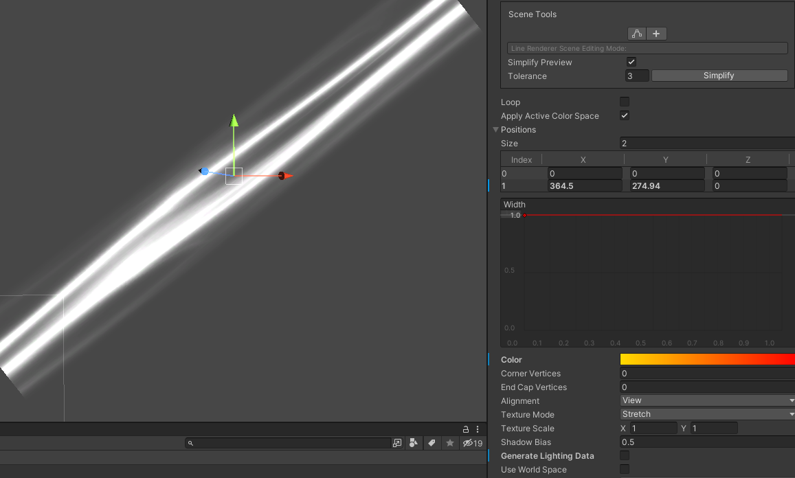
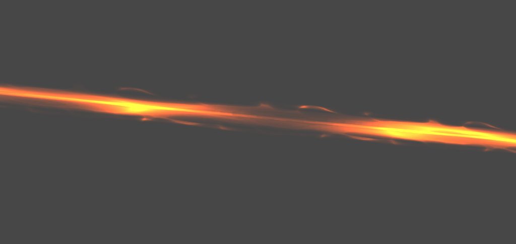
Hey I am looking to create a custom shader that will go on a LineRender. I want to make it so the texture I use on the material dynamically tiles based on the length of the line. Is this possible? I was thinking it might have something to do with the length of the quad the Line creates.
Isn't there an option on the LineRenderer component to make the uvs tile?
can i somehow sample the mip level choice / anistropic filtering distance in shader graph?
as opposed to depth?
Well another issue I am having is that my custom shader is overwriting the color of my Line Renderer. So is it possible for my shader to inherit the LineRenderer's color?
Good catch, you are right 👀
fixing that fixed the output to be as expected as well
Oh sweet
I figured it out
Line Renderer is setting the vertex color
I can use that 👀
There's a Sample Texture 2D LOD node, unless I'm misunderstanding what you want to do
Is there a way for me to make a material not affected by fog in the shader graph?
Like with a custom node
Should be able to use a Custom Function node with
#undef FOG_LINEAR
#undef FOG_EXP
#undef FOG_EXP2
``` Will need `Out = In` in the function too, so you can connect it somewhere.

Alternatively `#define MixFog(x,y) x` may also work, though it is a little hacky 😄In the custom function node what should the outputs be?
Depends where you connect it. Vector3 in and out is probably easiest, connected to Base Color.
The function shouldn't edit the value, just pass it through so that the code is included in the generated shader.
I haven't connected anything yet and I'm getting an error

nvmd I fixed it
And I should connect it to the base color option on the fragment?
You need an input too, so you can pass your current Base Color result through.
Name them IN and OUT or something. Then add OUT = IN to the function code.


Hopefully that works then?
If not may need to try File mode instead, as the #undefs might need to be outside the function scope.
I changed the format to file but am getting a weird error


You need to change the name of the function
Also remove B input
I have a shader that is centered on object center, but I need it centered on object bottom left corner
Is there an easy way to translate every value over by 0.5? to move them all over?
I tried adding 0.5, and multiplying by 0.5, neither worked
I tried plugging it into tiling+offset but that destroyed the values
how do you "move" values in shadergraph?
Yeah that fixed the error
How do I write what tiling and offset does without using that node? Because its also destroying my values and I dont know how to correct that

top is what it should look like, bottom is what it does look like
how do I retain the top look and then offset it
I need to move the fact that it intersects at the dead center to intersecting at the corner
It's equivalent to UV * Tiling + Offset
If all offset is is addition, why does addition not offset mine?
Its still centered in the middle so that cant be right

You would need to offset before the Fraction
That worked!
I am still getting a very tiny ammount of distortion at the extreme edges and im not sure why, but otherwise its centered right now

I am using a Panner and I want to randomize my UV offset for each of object using my shader, so that the scrolling effect looks less repetitive. Is there some sort of input I can use to randomize my offset?
I don't want to use world position because these objects will move, and if I randomize the offset based on world position it'll look janky
Could provide an offset via a property then, and set from C# using renderer.material.SetFloat
There are several objects, all sharing one material
Will that work per individual object?
I think the tutorial has this too. I believe it's because the Direction from the Camera node should be swapped out for the View Direction node. (Could also use Tangent space to avoid the Transform node then)
Ill try that out. I have followed a few different tutorials on this same effect and some view instead of camera, Ill try copying from there
After testing it out the error disappeared but the fog still affects the material
Or will that cause all objects to just update to the same offset
The purpose of using renderer.material is so it creates an instance/clone. This would break batching and be more draw calls though. But if using URP/HDRP, the SRP batcher can still function, so it's fine for those.
What's the performance cost of this?
You also should destroy the clone in OnDestroy
Im using it for the line renderer and will have several dozen lines
That worked, thanks! Distortion is gone

Not sure, might have to try it and profile.
What fog is this? Is it URP / Built-in?

URP
This is also not working
It's just setting all the materials to the same thing
Oh wait no
it is working but the number isnt properly randomizing
Well actually I'm not for sure I have the urp enabled currently but the fog is under lighting and other settings
Then it should work afaik. I'm not at a computer to test though. Maybe try the other method I mentioned earlier : #define MixFog(x,y) x
That actually surprisingly worked perfectly
@grand jolt Just thought, but maybe you could pass a seed in via the alpha channel of vertex colours, if you aren't using transparency
Wouldnt that seed be the same every time?
Not sure what you mean. Can set it from C# by adjusting the mesh data
Actually no, it's a LineRenderer, just use it's .color
Would mean you can stay with a single material though for the dynamic batching purposes that I assume LineRenderers use
hmm
I might have to use instances anyways if I wanna animate each line
with some sort of shader effect
Okay, just an idea 👍
I got the individual instances to work
color didnt work unfortunately
Thank you tho :p
anyone knows how to get a mid point for a flipbook node ?
anyone have to share their shader stripping code (as my URP lit takes..... 160MB :D)? I am too beginer to learn it from "extensive" unity documentation about that which leads to one good blog without any examples 😄 (all exmaples links are dead)
I would imagine you make ShaderVariant, or log all shaders you use in run time. (did that), then make a list of those shaders somehow (did not did that) and remove all others on build..... making the list of them in correct format is still a mistery for me
im trying to make a steak cooking shader(the cook-ness can be changed with float value) and it's kinda f*cked up

- Look at how to do custom lighting
- Make a single point light
- step 2 , two times more
Or, why don't you simply use a lit shader with 3 point lights ?
hi guys
does anyone know a website or source from where i can download free textures
containing albedo and normal map
preferrably some grass, or underwater ground texture
ty so much
hey friends
does anyone know how to get rid of this transparency bug

the fins in the back are rendering ontop of the blob in the front
I'd use the Override mode (or Lerp, which is equivalent). Use the raw texture in the first port, cooked texture in second, and a float property in third. Can then control that property from a C# script slowly changing it from 0 to 1.
Is there any way to make a transparent shader graph still write to the depth/scene color buffers?
Not in URP afaik
hello guys !
A question about Hdrp and Decal projector. Does it work on transparent materials like glass ?
This is how regular transparency works, if the most part of your object is opaque and a small part transparent, favor the use of two materials
Yes, if you enable "decals on transparent"
Else you need to do some trickery like transparent depth prepass
@amber saffron Ok, thanks for your reply. Where is this " decals on transparent" ? inside the "HDRPRenderPipelineAsset" inspector ?
kay, the sad point is that i dont have cooked texture for steak
maybe i should change the model that has both texture
On th decal projector itself : https://docs.unity3d.com/Packages/com.unity.render-pipelines.high-definition@15.0/manual/Decal-Projector.html
@amber saffron Thank you again, i've checked every boxes, excepted this one... ^^'
Hello, I am using the pixel perfect camera from URP. When I try to get the camera height inside of a shader graph, I get the same value everytime even if I change the orthographic size of the camera (using cinemachine & the CinemachinePixelPerfect extension)
The value changes inside the inspector, but not in my shader
It doesn't necessarily need to be a separate texture then (though may be easier that way). Could be a Vector4 produced in the graph that you want it to look like when cooked.
https://github.com/JimmyCushnie/Noisy-Nodes I imported this package into my project but every single node shows pure black no matter what values I input. Has anyone else had this experience? How did you fix it?


GitHub
Adds various noise generation nodes to Unity Shader Graph, including 3D noise nodes. - GitHub - JimmyCushnie/Noisy-Nodes: Adds various noise generation nodes to Unity Shader Graph, including 3D noi...
@amber saffron I fixed the displacement map yesterday. But I have a question about normal map now. Is this correct?

the highlighted func basically means this transform node right?
I don't see the full lines in this screenshot, but I guess so.
What bothers me is that the function is named "WorldToTangent..." but it uses a variable named "t2w" which I interpret as the inverse XD

@amber saffron something is not looking right, the white one is the correct one, but the other one looks similar but not quite.


The main big difference I see here is the ambiant lighting
no I mean the lighting is obviously different but I am talking about the wave peaks, the white one looks correct, the other one kinda looks like inverted peaks. I think it is more visible when in motion.
Invert the displacement value 🤷
the displacement is okay, not the normal.
Invert it
before I fall down a rabbit hole, is shadergraph capable of doing this? Im pretty sure its some form of raymarching

I have the hlsl file for that shader but I don't know how to read it to translate it over very well
in theory yes but it will take a lot of custom nodes
I figured that might be the case, on the upside I have the HLSL for it, on the downside I lack the comprehension to copy it over most likely
from what I know raymarching uses a lot of recursion (for loops with functions) and shader graph doesnt have that
- input for the shader would be hell
Hmm maybe this is an X/Y problem - I'm specifically looking for a way to make it seem like a cube is volumetrically transparent with inclusions that have depth to them
Visual example would be like a blob of resin filled with ink or glitter
And that shader there above is the only example file I could find that even remotely began to approach that - the idea of layers of suspended 'texture' within the mesh
"volumetrically transparent"?
Yeah im trying to find a visual example that will explain it more obviously
Hi, I'm trying to make a special shader where I try to imitate the 'sea sparkle' effect. So when a player takes a step, it kind of radiates a glow into the water. How would you go about it since I don't really know where to start.


transparent object with volumetric 'texture' suspended in it - Im probably misusing the term volumetric
in comparison to the dice you can see why I thought this could do it

honestly I cant rally think of a way to do it without just modeling it
unless you are ok with the current example and just would like to add transparency
Well, there is a lot more I would want to do with it, all I am really trying to do is get a base line shader that I can then adjust to what I need it to do
I don't know what limitations there are but that looked like a good starting point
I've tried 3D noise nodes but the noise isn't 'within' the object, its just plastered on the outer surface
I've looked at Parallax Depth maps but I don't think they will work in this use case, since I want things to be behind things, its not just height map depth alone
what kind of "modifications" would you want to do to it
the only other shader way of doing what you want would be to make a sort of volumetric cloud shader from the 3D noise u got
just really thick
I can look into that, cloud shader
if you are going to play around with shader graph I would recommend to get this:
GitHub
Adds various noise generation nodes to Unity Shader Graph, including 3D noise nodes. - GitHub - JimmyCushnie/Noisy-Nodes: Adds various noise generation nodes to Unity Shader Graph, including 3D noi...
Yup I have it already
nice
thats the 3D noise I have that I was refering to
Ah naw textures arent 3D, at least not ones photoshop makes
fair enough

the text of the raymarch (along with a bunch of other superflouous stuff I don't care about like animating the blobs position and color)
could u send me the whole thing
Sure, 1 sec
https://bronsonzgeb.com/index.php/2021/02/27/particle-metaballs-in-unity-using-urp-and-shader-graph-part-1/
gunna start reading this tutorial I found, maybe itll lead me in the right direction
just a slight modification : )
but to make it look like there is resin around the blobs would be hard
This metaball tutorial started diverging from what I needed it to learn from so Ill take a look at yours now
Shader file won't even open in visual studio, getting this error

I'm not sure what you changed, this looks like its still a big long shader code thing, I am trying to translate it to shader graph so I can modify it in a way I understand, sorry if I wasn't clear about that
thats odd
yeah righ
got carried away
but yeah... not posible
but a cool shader tho
Ill keep trying, I'm sure something close enough can be done
Hello, so I'm trying to recreate the effect in this YouTube Short in VR with URP and shader grapth, but it seems that the viewdirection node is returning a vector that is pointing to the camera center and not the center of each stereo eye.
Here is the Short
https://www.youtube.com/shorts/uLN69rtiu4Y
And btw if this is possible to do only with a Shaderlab shader I'm fine with it as long as you point me to a function that returns the correct vector.
(I did not find it here: https://docs.unity3d.com/2020.3/Documentation/Manual/SinglePassInstancing.html)

These small lights hold a little secret; they don't contain anything at all! Another quick answer, a series on quick techniques too simple for a longer video.
Don't worry, longer videos are still coming.
🐦 https://twitter.com/JasperRLZ
💰 https://patreon.com/JasperRLZ
🤼 https://discord.gg/bkJmKKv
🌎 https://noclip.website
🎵 Mike Morasky - Porta...
Thats just parallax mapping no ?
I tried to make it work with parallax but it gets really distorted by rotation and distance
but the problem is not making the effect
problem is making it 3D
thus the question
The parallax node should handle correct eye view direction I think.
Is it possible to have a semi-transparent mesh on a UI canvas that overlays on top of UI images?
Im trying to figure out the render type and queue but I am having no luck
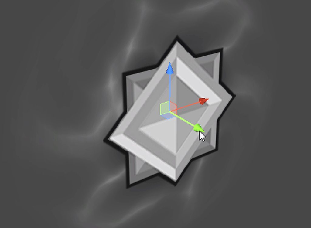
Well I am just using the default Unity shaders, is it even possible to render any transparent mesh on a UI canvas? With proper depth
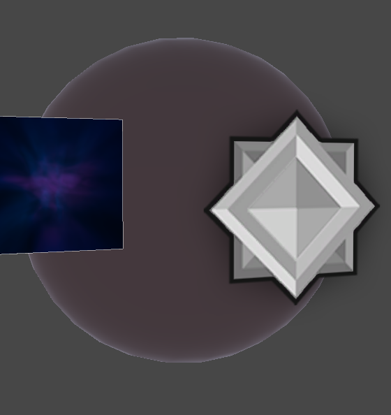

The only way I can think of doing this is to use a render texture and sort with that :\
Well, you've hit on the term, it's called "volumetrics" and there's tuts and shaders for that. It's basically ray-marching through a substance, and in your case doing refraction too. You're already on that track.
So IDK what more to tell you. You can look for other ideas in perhaps medical imaging where such is common, or in other "shader volumetric" things, like volumetric fog. But that's not helping you much. I mean, there's no magic bullet or technique here, just lots of GPU-expensive hard work. The cloud shader example was a good idea too.

Interactive Computer Graphics.
School of Computing, University of Utah.
Full Playlist: https://www.youtube.com/playlist?list=PLplnkTzzqsZS3R5DjmCQsqupu43oS9CFN
Course website: https://graphics.cs.utah.edu/courses/cs6610/spring2021/
0:00:00 Introduction
0:00:17 Applications
0:02:58 Volume Rendering for Visualization
0:28:49 Volume Rendering for ...
Thnanks for the link and kind words, I wont get discourage and I'll keep plugging away at it
Hi, I'm having an issue, I cannot find a way to add a master node onto my shader, may I be missing something here? I'm really new to Unity

Cubes are fairly simple, you could probably do it by populating the interior of a cube with spheres (which you'll have to shade yourself), calculating the new vector the light ray travels along when it enters the cube, then checking whether that vector hits any of the spheres
In that case, you wouldn't need to do any marching anything
Looping wouldn't be too cheap but whatever
what used to be the PBR master node is now the fragment/vertex nodes (already there by default, and you can't remove them)
Actually, thinking about it, you might be able to multiply your winnings by using grids of spheres instead of single ones (there's probably a way to check if you hit any sphere in a grid that doesn't cost much more than checking one)
np :)
How could I make a shader graph that makes the object ALWAYS render behind a certain object?
Hello, i'm kind of a shader newb and I am attempting to create a raymarching shader.
It's going fairly well, but I have noticed some artifacting when I displace the raymarched sphere by a high amount.
https://streamable.com/hs08w8

Some details seem to just pop in and out of existence when I change perspective. Does anyone have any idea what might be causing this?
I'm new to shader programming so bear with me,
If i have this kind of texture

And i want to have a value from 0 to 1 (vertically) on each "white group", how do i achieve this in runtime?

make an other texture with grayscale represent the value
from what i understand, what you are saying is not runtime calculation but using external application e.g. photoshop?
sorry for not being clear enough,
the original texture that i shared here is actually from a RenderTexture (from my camera, so it will move randomly on runtime)
and i want to calculate the value from 0 - 1 vertically on each "white group"
because the original texture will change on runtime, i don't think it's possible if i generate other texture using external app
In this case, this is no longer a shader problem
you have to use ur cpu to calculate dots out of texture then generate a texture with grayscale runtime
like iterate all pixels find the highest point of the dots and lowest...
ahhh i see,
thank you so much
Hello, I have a UI rendering question:
When using a list view, what are the benefits of using object pooling?
https://unity.com/how-to/unity-ui-optimization-tips#avoid-expensive-ui-elements this site says that pooling is used to reduce overdraw, but if each list element doesn't contribute much to overdraw, then is there any benefit to pooling the UI elements?
Or maybe I am misunderstanding it. From my understanding, simply disabling the "RawImage" component takes it out of the drawcall anyway, so pooling is not a big deal???
That is also not a shader question,object pooling only works well only when you have objects create and destroy frequently(like 100s per second), this normally doesn't apply to ui
Sorry, I didn't really know where to put it. The ui-ux channel seemed to be artist focused so I asked here because I had a lot of custom shaders in my UI components
Wait so there is no point in pooling ui? @west eagle
Alright, thank you. I was about to spend a lot of time making a pooling system for my list
by the way, unity have its own object pooling system https://docs.unity3d.com/ScriptReference/Pool.ObjectPool_1.html
do not make your own wheel
It just looks like you are displacing the sphere outside of the volume of the cube mesh you are using to render the shader, and as such the rays are starting already inside of the displaced sphere
You'd have to use some algorithm to detect the "groups" where continuous shapes exist. You'd then have to pass over the groups and calc the min and max Y value. From that, you can do a simple calc to get the % height.
This can be done in shaders, or on CPU. Compute shaders come to mind in this case, and flood fills, with later passes to detect groups. So each "fill" would be a different value for detection. Then you can pass over and detect areas of unique values.
Maybe....
Thanks for the detailed explanation,
i'll try to research more on compute shader & flood fill algorithm
do I have to mention anything specific in shader graph for 32bit texture inputs? 1st image is how it should look like, it is the R channel of 32bit image in built-in render pipeline. 2nd one is in HDRP, but it looks like less color depth. I need this for calculating normal and the normal looking less detailed as well.


2nd one is not "lit" btw.
1st how it should be and 2nd how it is looking in HDRP, see the peaks of waves are missing details


Hi all can anyone help me convert the following into unlit shader to surface shader, I have tried but I dont know how combine the appdata and v2f struct as Input for surface shader.
Below is my unlit shader.
Shader "Custom/Dissolve"
{
 Properties
  {
    _MainTex("Texture", 2D) = "white" {}
    _DissolveTexture("Dissolve Texture", 2D) = "white" {}
    _DissolveY("Current Y of the dissolve effect", Float) = 0
    _DissolveSize("Size of the effect", Float) = 2
    _StartingY("Starting Y point of the effect", Float) = -10
   }

SubShader
{
 Tags { "RenderType" = "Opaque" }
 LOD 100
 Cull Off
 Pass
 {
 CGPROGRAM
 #pragma vertex vert
 #pragma fragment frag
 // make fog work
 #pragma multi_compile_fog

 #include "UnityCG.cginc"

 struct appdata
 {
   float4 vertex : POSITION;
   float2 uv : TEXCOORD0;
 };

 struct v2f
 {
   float2 uv : TEXCOORD0;
   float4 vertex : SV_POSITION
   float3 worldPos : TEXCOORD1;
  };

  sampler2D _MainTex;
  float4 _MainTex_ST;
  sampler2D _DissolveTexture;
  float _DissolveY;
  float _DissolveSize;
  float _StartingY;

  v2f vert(appdata v)
  {
    v2f o;
    o.vertex = UnityObjectToClipPos(v.vertex);
    o.uv = TRANSFORM_TEX(v.uv, _MainTex);
    o.worldPos = mul(unity_ObjectToWorld,      v.vertex).xyz;
    return o;
   }

   fixed4 frag(v2f i) : SV_Target
   {
     float transition = _DissolveY - i.worldPos.y;
     clip(_StartingY + (transition + (tex2D(_DissolveTexture, i.uv)) * _DissolveSize));

     // sample the texture
     fixed4 col = tex2D(_MainTex, i.uv);
     return col;
    }
   ENDCG
  }
 }
FallBack "Mixed Reality Toolkit/Standard"
}
You can just ignore that appdata since it's internally handled by surface shader (I think) then you only need to convert v3f to Input like
struct Input
{
  float2 uv_MainTex;
  float3 worldPos;
}
Will i not have to include the vertex and uv variables from struct v2f ?
I get error when I try to call in the void vert function of surface shader.
The error says invalid subscript uv, vertex
What did you mean by this exactly? I am inexperienced, how would I use a grid of spheres instead of single ones? What does it mean to use a grid of spheres vs. a grid of single sphere?