#archived-shaders
1 messages · Page 247 of 1
Can anyone reccomend a resource for an invisible object that casts a shadow in URP?
pls tag me in respone

Out of curiousity, what's the declaration for tris? And how is it created in C#?
Thanks for the response :p The C# script doesn't seem to be the issue, since it's the shader that won't compile. Declaration is this: AppendStructuredBuffer<Triangle> tris;
I've also tried changing it to an AppendStructuredBuffer of floats and appending a float, just to see if it's an issue with my struct. Still got the same issue.
Yeah, the creation would only show up on use, not on compile. It has to be created with the append flag set. I guess I just asked out of a sense of completeness. But meh.
You're not trying to read from that buffer (as a regular UAV) anywhere in any kernels in the same file, right?
Since it may be a compiler bug, maybe break the kernels out into separate files, one for the append logic, another for reads and such.
Total SWAG (Silly Wild Azz Guess)
Other than that, I guess you should report the bug...
Yeah, not trying to read from it. I'm only writing data using using that one Append statement.
nice okay discord crashed before i could send my message
anyways I tried a second compute shader that writes to an appendbuffer and it worked. So something's wrong with my code, I guess
I don't really want to split the appending into its own kernel because that would be a lot of work, but I might give it a go if nothing else is working.
Here's my whole script, if anyone wants to take a look. I want to be clear I'm not looking for code review. I know it sucks and probably doesn't work lol, but that's stuff I like to figure out on my own. Just looking for help with line 370 preventing the compiler from working. (also yes there are like 280-something lines of precomputed values in total, sorry)
Hastebin is a free web-based pastebin service for storing and sharing text and code snippets with anyone. Get started now.
OK, since it could be a compiler bug...anything goes.
Maybe change something else.
Check that int3 and uint3 are matching up. Looks like tri is a uint3 in the struct and you use an int3 constructor. This is just before the append statement, so maybe the compiler is getting screwed up internally.
Or like that index variable. Starts at 0 in CSMain, and is an inout to the function, but it is always passed in as a zero (at least right now). So get rid of it temporarily, and keep track of index in the function. Just to generate different code, for now.
Since you tried a separate compute shader with append buffer in another test and it worked, doesn't sound like it's your setup that's the problem, so generate different code. Just my 2cents.
Otherwise, you're back to reporting a bug, that's all you can do.
I'm totally guessing here, but by eliminating line 370, you also eliminate dependencies. And the optimizer logic may throw away some variables as unnecessary BEFORE it tries to generate any resulting code from the remaining logic. So by throwing stuff out, it bypasses whatever is causing the error. But keeping line 370 intact forces it to generate the code to use all the stuff being calculated. And somewhere along the line, in the dependency chain, it gets messed up and pukes.
Thanks for catching that! Yeah, I just realized I wasn't using my index variable properly. It's correct that I set it to an inout; there's just more I still have to do with it that I forgot to implement because of this bug.
I'm gonna keep fiddling with the code. I really hope it's not the compiler screwing up its optimization. Thanks for your help!
Yeah, glad to, it's a curious thing!
I know the code is a work in process, I was just trying to think of things that you could screw with in the dependency chain of calcs.
Anyway, good luck. These things are the worst to track down...if you can track it down at all. Keep us posted!
Will do!
Oh, and this was hilarious, BTW. In an evil-viewer sort of way. lol
I mean, we've all had those days.... lololol
@meager pelican tracked down the issue
It only happens when I use Append in a loop
unfortunately I can't get around this by simply putting it in its own method. compiler's too smart for that
damn it, some nested if statements won't work either
god i hate this
Okay NEW problem now. The compiler is detecting this as an infinite loop????
for (uint i = 0; i < 16; i += 3)
i'm so goddamn confused what is even happening
Are you modifying the i inside the loop maybe?
Or what makes you think that it detects it as an infinite loop?
Nope, not modifying the value of i
Absolutely no idea. Sorry my code is super ugly and probably awful but you can check it out here
    {
        Triangle toAppend;

        uint edge1ID[2] = EdgeMap[edgesToConnect[i]];
        uint edge2ID[2] = EdgeMap[edgesToConnect[i + 1]];
        uint edge3ID[2] = EdgeMap[edgesToConnect[i + 2]];

        toAppend.v1 = vertexInterp(blfPos, edge1ID[0] + blf, edge1ID[1] + blf);
        toAppend.v2 = vertexInterp(blfPos, edge2ID[0] + blf, edge2ID[1] + blf);
        toAppend.v3 = vertexInterp(blfPos, edge3ID[0] + blf, edge3ID[1] + blf);

        tris.Append(toAppend);
}```like nothing there should cause the compiler to find an infinite loop, right?
What exactly does the compiler say?
Shader error in 'AppendTest': infinite loop detected - loop never exits at kernel CSMain at AppendTest.compute(355) (on d3d11)
I've been messing with the code a bit, so line 355 in the file I posted might be different, but here line 355 refers to that for loop
It's really strange that I didn't get this error when I was using an earlier version with an if statement that could break the loop
so im setting vertex color via c# to = 0.1 under certain conditions as a test and when running my shader on it i get this result any ideas?


what are you comparing vertex color to?
Oh sorry it’s hidden just .1
Alright
if the interference goes away, you can shorten that range (absolute value of vert color minus 0.1, check if that's less than like 0.01) so it doesn't go over ur black area too
lmk if that works


did you do <= 0.11 or 0.1?
oh mb alright so .11 does work
cool! so yeah, it's probably an issue of calculating an exact vertex color. there'll be a small amount of error, probably much less than 0.01
I'll keep that in mind tyvm!
np!
the abs thing i mentioned earlier should hopefully work so u dont need two comparisons :p
I'll try it thank you again
no problem!
so I have a custom mesh export it to unity and some faces I cant see from the back/front , i know its because of normal but how can I make it so that the normals face both direction at the same time?
set it to two-sided in the material settings
every triangle normally would render the back and front, but gpus cull the back face to save on performance. so keep in mind that by doing this, you're rendering twice as many polygons
I am aware
and where do I find this?
oh shoot i just realized you might not be able to do that w the standard materials sorry
might depend on the render pipeline
sadly this sound like magic words since I just started putting some materials to my scene lmao
you can use your own custom shader to render both faces though
how can I make a custom one?
hmm shoot im not sure in SRP
but you could cheat and just make another mesh with the normals inverted
you using blender?
yessir
cool, so duplicate your mesh, then on the duplicate, go into edit mode, select all faces (you can usually do this by pressing 3 then A) and press Alt+N
that should bring up some sorta menu, which should have the word "flip" on it
Click "Flip" and that'll flip all the normals. You can join them if you want by selecting both then pressing Ctrl+J. Then you can export the models.
so , I have a custom mesh and I only want some sides to be that ( so that my pc wont crah when loading too much ) . I only selet the ones I want the normals to face both ways and your steps right?
oh, yes. And actually after you've selected them and flipped their normals, you can do Ctrl+i to invert your selection to all the faces but the ones you flipped, then delete them
to save a little more on performance :)
you'll want to delete faces only, not verts or edges or anything like that
so I duped , flipped and joined them
do you still have the flipped faces selected?
now I do have them selected
Alright, you just press Ctrl+i to invert your selection to everything else. Then you can delete those faces since they're just useless duplicates
oh, no this should be before the joining, sorry
yes
weird
what's wrong?
it didnt change at all

strange. is that a screenshot in blender?
yessir
oh, yeah, blender usually renders things on both faces
but unity culls backfaces, unless you're using URP where you can turn that off
maybe I missed something , after I delete the faces do I join them?
yes, or you can avoid joining entirely if that's causing issues. they'll just be separate models and objects in the unity editor
nvm I had to be in edit mode
ok so there was no need to invert anyting and I think I fix the problem now
now its facing both ways

Right. Groan.
Looks like a shader compiler loop unrolling bug (guessing).
The compiler will likely unroll that loop into several version of itself...
one for 0, one for 3, 6, 9, 12 and 15.
You could try a [loop] attribute that stops the compiler from unrolling the loop. It might be ignored though, compilers don't have to honor the request. IIRC.
https://docs.microsoft.com/en-us/windows/win32/direct3dhlsl/dx-graphics-hlsl-for
Iteratively executes a series of statements, based on the evaluation of the conditional expression.
Anyone knowing how to reference a switch from shader in amplify shader? ( I only know Shader.SetGlobalFloat...)
A switch like a toggle ?
It is under the hood using floats 🙂 0 for disabled and 1 for enabled
@amber saffron thank you 🙂
yeah, the [loop] attribute didn't work. I tried [unroll] though and that seems to fix it?
ok so I kind of asked this the other day, but let me try a different angle.
I'm sending a texture to the shader to tell it what to render on the screen, and with actions like digging dirt or placing things i want to update this texture, but right now i'm literally just using setpixel and reuploading the entire texture every time which feels horrible.
Is this something I should use Graphics.Blit for and a render texture instead perhaps? I'm not sure what a more performant method would be.
@meager pelican alright, looks like the [unroll] fixed it!! and for some reason that fixed the other compiling issue too!!! thank you so much!
Rendertexture and blit is the way to go, or if you want to prevent yourself the hassle of writing this, you could use custom render textures 🙂 https://docs.unity3d.com/Manual/class-CustomRenderTexture.html

Use this with a shader that would write the needed pixels, and call an update on the custom render texture only when needed.
Thank you 🙏 I will look into it
Hey guys, wondering how do I learn what each variable is in Unity's shaders. For example the 'i' variable in the fragment shader, where can I look up what properties it has, functions I can call on it etc. The doesn't seem to be very good documentation I can find?
Or for example the 'step' function? Where do I find how to learn about this?
i is just a name so could be anything, but it's probably just short for input. It will likely have a type like v2f (vertex to fragment), which would be a struct defined earlier in the shader file. (Some examples here : https://docs.unity3d.com/Manual/SL-VertexFragmentShaderExamples.html)
You should be able to see what properties/fields it has in that struct declaration. Each field would be set by the vertex shader - which also has it's own input struct (typically named appdata in Built-in pipeline), which obtains data from the mesh via POSITION/TEXCOORD/NORMAL etc "semantics" : https://docs.microsoft.com/en-us/windows/win32/direct3dhlsl/dx-graphics-hlsl-semantics
As for functions, HLSL has some intrinsic functions, like sin, cos, saturate, step, dot, mul, etc. They are listed here : https://docs.microsoft.com/en-us/windows/win32/direct3dhlsl/dx-graphics-hlsl-intrinsic-functions (Can click on them to see which shader models/types they support)
Unity also provides some functions (e.g. UnityObjectToClipPos) and macros (e.g. TRANSFORM_TEX), though that depends on the render pipeline. Some documentation here for Built-in RP :
https://docs.unity3d.com/Manual/SL-BuiltinFunctions.html
https://docs.unity3d.com/Manual/SL-BuiltinMacros.html
Can also read the code. e.g. https://github.com/TwoTailsGames/Unity-Built-in-Shaders/tree/master/CGIncludes (UnityCG.cginc typically being the main one).
For other pipelines (URP/HDRP) can see the ShaderLibrary folder in the package, or look under https://github.com/Unity-Technologies/Graphics.
Hello just a question 🙂
The situation:
- I have one shader with one Texture (which I want to change for each GameObject)
- There are "many" (100-500) gameObjects (which are generated for terrain) with that shader, and each has a different texture
The questions
1.) Is there some kind of limitation for the count of texture I can use in the game from RAM or VRAM size?
2.) Is there some kind of known count - how many of these objects (not movable, just only static objects with texture) can be in the scene without decreasing the FPS
3.) How does even Unity works with these Textures - are they released as the gameObject became not active? Or out of the screen (e.g., by culling)
Thanks for any insights 🙂
- I'm not a pro when talking about how this is managed, but from my understanding, as much textures as needed are fit into the vram, then it starts to pile up in the ram and swaps (bad), and maybe later it also goes into some disk cache and swaps even more ?
So there is no real hard count for the number of textures, it depends on their memory size.
-
This not only depends on the number of texture, but also how the objects are batched together. Less batches (draw calls) = more performance. If using GPU instancing you can drawn fast a crazy amount of objects
-
AFAIK, a texture is kept in vram even if not rendered unless space is needed
For you use case, you might want to try to have a single big texture as atlas for all your objects that contains all the smaller textures, and draw all the objects in a single draw call, offseting the UVs to select the texture to display.
You might also want to look into virtual texturing, but I don't know a lot about how it works
Oh okay - thanks 🙂 This is enough for me (for now 😄 )
Hi guys, does any one know how to visualize point cloud with shaders? I have a lidar scan of vertices locations only. The problem I have now is that I have a obj file of vertices only, and unity does not recognize any of the vertices since there is no mesh.
What about this ? https://github.com/keijiro/Pcx

GitHub
Point cloud importer & renderer for Unity. Contribute to keijiro/Pcx development by creating an account on GitHub.
Oh thanks! Somehow I missed this. Let me take a quick look.
lol. UNroll? lol.
I thought it couldn't unroll (per the error message).
Well, if it's a compiler bug, anything goes. ROFL.
Glad it helped. What a crap shoot! Hang in there!
@woven haven Don't cross-post. Pick a single channel.
idk which one it's for shader or post processing
no wonder I couldn't find any current info on it! 😂 Thank you!!
I dont really know where to post this question, but why does my texture looks a bit weird

On the bottom it looks okay, but on the walls it is so buggy

Can someone explain how to set up a public switch in Amplify Shader, I dont know how to make it public xD
Thats obviously because you havent uv unwrapped the model properly
UV mapping baby
So, I've got an array of arrays of ints in my compute shader, which I've defined by simply declaring it, with all its values already typed in.
like this, yknow?

just a bunch of precomputed values
for some reason, every time I try to read an integer from these arrays, it always returns zero
what am I doing wrong?
If it's outside a function, I'd try adding static before int. I'm not that familiar with compute shaders or 2d arrays like this, but typically global variables in hlsl default to being an external input and default to 0. Marking them as static instead should change that.
hmm, marking it static seems to have made them all null or something. I'm running comparisons on different members and it always returns false, (despite including both <= 0 and >= 0) meaning it's not anything in the integer range
Then not sure sorry
@unique oarI'm with Cyan...I'd say the same thing.
Adding "just set it from C# if it won't initialize when static".
If you need that same table in several shaders, use a shader global.
Another thing to try is a single-dimension array, and compute row/col the index yourself. That might aid you with the SET functions.
I'll add IDK why you often have to do this from C#, since the compiler should just allocate an internal CBUFFER for it and load it with the shader. And IDK if it is Unity specific issue or shaders in general, but I've hit it before and end up just doing it from C#.
Wouldn't that have to do with an array like that basically being an array of pointers? I guess GPU wouldn't like that.
Try declaring it as static const
now they seem to all have been initialized to -1...
im so done with this 💀
gonna just scrap my whole shader and script and start fresh. maybe it's just something wrong with my code. i'm staying forever fcken doubtful of the compiler though, with the way it flagged loops that terminated after only 5 iterations as "infinite loops"
NO I KNOW WHAT THE ISSUE WAS
had some integer variables corresponding to moving right, up, and backward throughout sample positions
they were not static
thank you guys so much im sorry i wasted your time lmfao
Can you explain a bit more what the issue was? I'm curious.
So, it's a marching cubes algorithm, and I'm representing each 3D sample point with a single integer index. The sample points x, y, and z indices can each be from 1 to 8, and thus there are 512 possible single-integer indices. Increasing the index by 1 corresponds to a shift to the right, increasing by 8 corresponds to a shift upwards, and increasing by 64 corresponds to a shift backwards. I had these amounts (1, 8, and 64) stored as their own variables, so I could just do index + back to shift backwards, really just so i wouldn't make any mistakes. However, I hadn't marked these variables as static, so they were all initialized to zero
I'm still not sure why it caused such widespread issues, and so I'm probably going to rewrite my whole algorithm again anyways because it's obviously so messy
But that seemed to be the crux of the problem
I'm really not sure why that only started causing the shader to return no triangles (and thus seem as though all the values in my table had been initialized to -1)
But it's hopefully something I won't have to return to after I rewrite my shader.
Just finished rewriting. It fully works! Thank you all so much! I would have probably just given up partway through if you guys hadn't helped me out there 😅
Shaders are a pain to debug, but it feels great when they finally work.😬
That's only on the C# side (managed references in .NET), on the GPU side it would end up being mapped to memory directly. The SetFloatArray() routine would end up building that memory block of data from the references, somehow.
unity 2019: i'm trying to make a render pipeline asset, cuz otherwise i cannot do anything, but i don't seem to have the option to create a render pipeline asset?
I thought there is a core pipeline asset without importing from the asset manager

you need to install one of the SRP render pipelines to be able to do this (URP or HDRP)
Builtin Render Pipeline doesn't use a pipeline asset
right, then i need to get LWRP
and now find a way to get custom shaders to be rendered..
How does one write a shader for text mesh pro text ugui so that it animates the hand writing effect? You should be able to see each stroke being drawn out. Sort of like the first 5 seconds of this video: https://www.youtube.com/watch?v=GbMX20YoNTw&ab_channel=SonduckFilm

Learn how to create the handwriting effect! In this After Effect tutorial, we will take text and animate it on with a “write-on” style. This effect is very easy to do and there is two ways to do it. The fast way where you can add the stroke effect to your masked outline and animate the end parameters. Or the best way where you use the pen tool t...
I don't think you can do this directly with textmesh pro text and its font atlases.
How would I implement this : have a glyph atlas with the strokes path stored in a dedicated channel (0= start of stroke, 1 = end), and us this as a mask to display the drawing line.
weird, i thought you can make shaders work without render pipelines
You can
i made a lwrp pipeline, made somehting in shadergraph with fresnel noise and a texture, compiled it and put it in a normal .shader file, removed the lwrp, made a material using that .shader file, but the fresnel dissapeared
The texture2d did show correctly, but the effect was lost..
i need to work with no rp, and wanna make an edge shader..
SRP shaders are not compatible with Built-in RP shaders
What is the "anything" you cannot do here, but want to?
I feel like you're mixing up terminologies
that was a problem of not having lwrp imported
and "anything" meant "do any shadergraph work"
i thought making a shader in graph is miles easier
Shader graph is SRP only, until very recent unity versions
Yes basically
Non-srp shaders were all hand-written back in those verisons, or authored with something like Amplify
i did find about Amplify, but idk what it is, i thought it was proto shader graph
Making the shader with shader graph in 2021.3. for built-in RP and bringing it back to 2019 might work, but it's a long shot
god no
imma be real, im using 2019 cuz im working on vrchat stuff, and was wondering how their big shaders are made; thought you can make something easily, and you don't need a shader wizard but.. yea, thanks
Amplify is an independent, commercial shader editor much like SG that was developed for built-in RP before SG was a thing
wait so.. with no render pipeline, can i get any shader from.. say, shadertoy and import it to unity?
I see, thanks for the insight. I don't have any experience making a glyph atlas. Would this be easier or would key framing the handwriting effect of each font using the sprite renderer and animator be easier?
Key framing is also not an option.
In the tutorial you've shared, you can see that he is basically keyframing a curve.
Something "close" that you can maybe try is to use a trail renderered and keyframe it's position to do the drawing, and use a text texture as mask over it.
But this need to be done for each individual text, and can't be generic.
Shadertoy is even more specific, but yes, you can import shadertoy shaders in unity, to display them on quads or other meshes
Some tools even exist to help you in this process : https://github.com/smkplus/ShaderMan

GitHub
Convert ShaderToy to Unity HLSL/CG. Contribute to smkplus/ShaderMan development by creating an account on GitHub.
following a tutorial for a cel shader, now I test things out but shadows don't get cast on objects... is this normal or did I do something wrong?

How do I do I replace the white in my shader with another color, I've tried all the blending stuff without success
Yeah you need to enable shadow casting. If you are writing hlsl shaders thats super easy. Just add in a usepass with the shadow caster pass whatever its called. I cant remember
You can also fo it yourself, its not very hsrd either but i don't remember how to do that since using usepass is just so much easier and its the same thing anyway
Oh, well idk. I don't really use the shader graph that much. Especially for cel shading
You can probably find it on google if you try searching for enable shadowcaster in shadergraph
ah ok I'll do that. thanks :D
Though id think whatever tutorial you are following would add it as well 
I may have missed it
Did you try lerp?
i did find a way by weird manipulations
how would one separate a gradient into a few steps kinda like a toon shader
You would use the step function
@white marsh The shader is already casting shadows, the problem is it isn't receiving them.
@dusty creek You can calculate the shadowAtten via a custom function - the tutorial might already be doing that, hard to say without seeing it / the graph. e.g. Should be using GetMainLight with a shadowCoord parameter :
float4 shadowCoord = TransformWorldToShadowCoord(WorldPos);
Light mainLight = GetMainLight(shadowCoord);
If you're using an Unlit Graph, you also need to specify some keywords for it to work (mainly _MAIN_LIGHT_SHADOWS, but ideally also _MAIN_LIGHT_SHADOWS_CASCADE and _SHADOWS_SOFT). Can set them up as Boolean Keywords via the blackboard.
Alternatively I've got a package which includes some SubGraphs, like "Main Light Shadows" which returns the ShadowAtten & handles the keywords for you. https://github.com/Cyanilux/URP_ShaderGraphCustomLighting
many words I don't get but I think I can figure it out with this and some googling xD thanks a lot <3
Btw which tutorial are you following? There is a really in depth and detailed toom shader graph tutorial on YouTube by Ned Makes Games
Can also try a Posterize if you want multiple bands. (Out = floor(In * Steps) / Steps;)
Steps may give you more control though
that's the one I am following, though I thought I had to skip the shadow one since I already have shadows xD
I'll see what happens if I do the shadows as well
old tutorial, I don't have a field to put those keywords in, and if I type them in into an invalid keyword field they don't go to valid keywords, they just disappear. and if I try to increase the size of valid keywords they go to invalid...

they are case sensitive and they need to be added as a keyword within the shader graph, note that name and the keyword is not the same
yea the keyword is in the reference
after that the tutorial says to add the keywords

only 1 of them seems to be active. the MAIN_LIGHT_SHADOWS but not the _MAIN_LIGHT_SHADOWS_CASCADE and _SHADOWS_SOFT

Scope should be Global really. And shouldn't need to manually add them in the debug inspector, that's a bit outdated.
The other keywords may only be "active" if they are required by the settings on the URP Asset. It's still good to support them even if you don't need them though.
_MAIN_LIGHT_SHADOWS is the important one, but you need that leading _! You should then be able to obtain the Shadow Attenuation value from a custom function. I'd temporarily attach it to the Base Color output to check if it's working.
I added the _, I have nodes that multiply Shadow Attenuation with Distance Attenuation and then multiply it with my previous color output yet the shadows still don't cast over objects other than the terrain. I think I'm gonna follow a more up to date tutorial
Is there a good way to speed up my GetData calls from compute buffers? Using the profiler, I found that the biggest source of framerate drops is from reading data from a compute buffer. Here's my code.
    void RunComputeShader(float[] samplesArray)
    {
        // Set up triangles buffer
        triangles = new ComputeBuffer(4096, sizeof(float) * 12, ComputeBufferType.Append);
        triangles.SetCounterValue(0);
        marchingCubes.SetBuffer(0, "triangles", triangles);

        // Set up array of sample points. Set samplePoints buffer to array.
        samplePoints.SetData(samplesArray);
        marchingCubes.SetBuffer(0, "samplePoints", samplePoints);

        marchingCubes.Dispatch(0, 2, 2, 2);

        // Get length of triangles from compute shader.
        ComputeBuffer.CopyCount(triangles, counter, 0);
        int[] countArray = { 0 };
        counter.GetData(countArray);
        int triangleCount = countArray[0];

        // Read the triangles from the compute shader to the triangle array.
        Triangle[] data = new Triangle[triangleCount];
        triangles.GetData(data);

        GenerateMesh(data);
}```marchingCubes is the compute shader. A triangle struct contains four vector3's. (three for each point, one for the normal)
The getting of data takes about 1ms to execute, which is pretty long when I've got lots and lots of objects. I know there's still more optimizations to be made, but this would be a pretty big one to get out of the way.
@unique oar I still am new to compute shaders so take my word carefully. As you seem to recognize, transferring data to and fro the the GPU is time consuming. What does the GenerateMesh function do?
Depending on what that function does, it could be possible to never retrieve any data from the GPU, and therefore save a lot of time.
Also, could you upload your c# and .compute file with the extension ".cs" (so I can look at them on discord without downloading them).
Why are you so sure it's the "data retrieval" that takes that much time? Did you check the profiler?
I do need to transfer data to the CPU, as the resulting mesh is used in collisions. GenerateMesh simply turns the retrieved triangles from the buffer into a mesh, then assigns that to the Mesh Filter and Mesh Collider.
I can do that in a sec. Will need to clear out some lines of commented-out code that isn't relevant. Sorry if my code is bad, I just started writing compute shaders a few days ago :p
Profiler sampling. The BeginSample and EndSample methods, specifically.
Okay. Where did you put them?
I really doubt that data retrieval itself takes that long. It's probably mostly how long the GPU takes to process your data in the compute shader.
BeginSample before the Dispatch call, EndSample after. BeginSample before all the data retrieval, EndSample after.
Well, since you do that all in one function it all happens immediately. So you basically dispatch the shader and wait for it to finish it's work.
So it's most likely what I said.
But 1 minute is a lost anyway. Either you feed a hell lot of data into the compute shader or the algorithm is slow.
@rich roost here are the scripts. The C# one is pretty messy, but the RunComputeShader method should be mostly coherent lol :p
heres the compute shader
The C# script doesn't wait until the compute shader is finished?
that just doesn't sound right :/ I'm getting the buffer data like, within a couple lines of the dispatch
itd have to wait or else i'd be getting an incomplete buffer
That's what get does. It waits for the shader to complete.
You can't get "partial" data from the shader.
ahh, I see
It's either all or nothing.
yeah well of course lol
Anyways, how could I measure the time it takes for my shader's kernel (hope that's the right terminology) to complete, then?
That's pretty much the metric that you get imho
ahh
Looking at your shader, I'd assume that you feed too much data into it at once making it that long to process.
i was initially running it with 1x1x1 groups, but when I switched to 2x2x2 and doubled the mesh size in all directions, it didn't seem to affect the performance too much?
I'm still very unsure about what the optimal sizes are for everything
Ughh... I tend to forget that as well, but I think something like 8 by 8 is a good number. With 1 I'd assume that it just uses one thread for all the computation.🤔
oh, no i've been using 8x8x8 threads, but i switched from 1x1x1 to 2x2x2 groups of those threads (in the dispatch call)
sorry 😅
Ah wait, the threads numbers are defined on the shader side..? I'm really not sure about it, might need a refresher.
Yeah, but I remember that groups of threads also had an effect on that.
So in a compute shader there's [numthreads(x,y,z)] which is written before each kernel. It defines how many threads are like, assigned in each "direction"? not sure how to put it
What I can suggest is have a look at Sebastian League's implementation and compare it to yours - see how fast it completes compared to yours and differences there are.
but in your dispatch call, you can invoke the kernel multiple times in each direction. i'm invoking the 8x8x8-threaded kernel twice in the x, y, and z directions when I use dispatch
I suppose I could, but our approaches are still a bit different. He uses HLSL libraries for noise, whereas I currently use C# libraries so I have a bit more control over the point values (although I'm going to switch to a blend of the two later)
I've had a look through his implementation recently to see if there's much we did in the C# script differently, but when it comes to getting the data, it looks to be about the same
Yeah, that's why I think the difference is either in the amount of data you try to process at once or the algorithm of your marching cubes.
Try different chunk sizes and see how they affect performance.
hmm, strangely, I think running 2x2x2 gets me the same performance
I'm just sort of eyeballing it by running the shader stuff once per frame, and I don't see a difference in FPS
That doesn't change the amount of data that needs to be processed.
yes it does
Not overall
I'm using 2x2x2 instead of 1x1x1, i'm not increasing or decreasing the chunks
i am processing 8 times as many sample points when i switch to 2x2x2
That's what I mean. Try decreasing the chunks size.
well that's what i did...
to increase or decrease chunk size i have to change the threadgroups
No. It still gets processed in one run.
what
That's not how it works. It's all still considered one run of the shader.
Reduce the size of chunks you try to process per dispatch.
but i'm running it 8 times as much per dispatch aren't i...?
like,
the dispatch is Dispatch(0, 2, 2, 2) versus Dispatch(0, 1, 1, 1)
sorry im very confused
I'm not 100% sure, but dispatch groups are not how many times you run the shader, and even if it was, you'd still get the results only when all of them are done.
You need to reduce the amount of data you try to process with each dispatch.
okay, what do you mean "data you try to process"? As in the data I pass into the shader as a computebuffer to run my calculations on? because I'm decreasing that.
the data it puts out is also decreased in size. the amount of data it has to perform calculations on is decreased
Yes. That.
So decreasing that doesn't have any effect?
Correct
Okay. And you're checking with the profiler each time?
Yes. It's only slightly, slightly slower to use 2x2x2. As in, like within ~4 or 5 milliseconds. And that could probably be mostly attributed to the mesh creation on the CPU side.
I'm not talking about dispatch groups. Why do you keep on bringing them up?
because it's related to the amount of data I'm processing. Altogether, the kernel uses 512 threads (because it's declared with numthreads[8,8,8]) If I want to process more than just 512 data points per dispatch, I need to increase the dispatch groups
and thus get the shader to process more data, which is what you were asking me about
Hmm... Okay. You're right about that one.
Can you share the code whith the profiler samples?
@kind juniper@unique oar
The GPU hardware itself has a limited number of resources at various levels.
For example, each core is a resource. So if you check the specs on your GPU you'll see that it has N shader cores. This varies by make/model.
It also has N texture samplers, and N whatevers.
So these limited resources are allocated at their own levels (core level, or card level....)
So it is certainly possible to allocate 512 threads to run at once, but if you only have 256 cores on some card, you're screwed....some threads are not going to get cores allocated and be suspended. Similarly, some threads may be limited by access to samplers.
Then there's the infamous "vector register pressure" that I always seem to hit in my code. lol. So I'd like to be able to run, say, 5 threads per core (because they are using latency hiding), and X cores per group but I can only run 4 thread and x-whataever per group due to the # of vector registers I've used. But vector registers are faster! So I want to use them! Arrggghhhh!
So in reality, @unique oar, it is all going to depend on WHAT you're doing per core as much as it depends on the # threads you're running at once. The way to check it out is to use a vendor-specific GPU profiler. I have an AMD card, for various reasons, and I use their GPU Open tools and GPU profiler to capture a frame. It will show me the wave-stats, so I can get a feel for how efficiently I've allocated resources.
Then it's "just" a matter of seeing what takes the time where.
Also, it might give you more detail about readback timing. IDK, I don't usually do that, so can't offer insight into it.
The point is you're trying to avoid...under-allocation...of resources, but also trying to use what you have most efficiently. Sometimes you can change a few calcs and get an extra core running per wave. The GPU will use latency hiding to allocate thread-groups and get them started up, while they're waiting for a result from say a texture sample read (texture samples are slow, but latency hiding "hides" that fact from you to a degree). So if you dispatch an [8,8, 1] thread group, you'll end up using chunks of 64 cores, and when they all do texture samples, the GPU will allocate ANOTHER 64 core group, and get it started up as fast as it can, and maybe a few more of em too, and then as each texture read finishes in one group, it can get more texture reads cranking in the next group and finish off the first group of code, and then move on to the next group...
I'm no expert, and it's really hard to envision all these dependencies, but basically think of stacks of thread-groups, processing their stuff, and by the time it gets to your shader you have a thread-id, group-id, instance-id, and can compute things.
But it isn't surprising to me that, given the fact that the GPU automatically creates a ton of groups for latency hiding, the comparison of [1,1,1,] and [8,8,8] may not be what you'd expect. Because in the end it is still limited by some resource.
And one other thing to keep in mind is data structures and layout and memory bandwidth. So even how data is packed and read back is important.
Arrrrgggh...I'm talking out of my butt here, but I think I've got the general idea.

In this video, presenter René Van Oostrum provides a general introduction to ROCm and programing with HIP (Heterogeneous-Computing Interface for Portability).
CTA: https://www.amd.com/rocm
CTA: https://www.github.com/rocm
Watch the next video in the series: https://youtu.be/LG9G4aA28rU
View the full playlist: https://www.youtube.com/playlist?...
Hey, I want to use a displacement map (As seen in the image) in URP. How would I do this? I'm trying to implement this in a shader graph though I don't understand how to make it work.

I've looked up multiple solutions but they don't seem to help me
Sample the texture, use one of it's channels value as the displacement value. To displace just get the vertex pos and add the value to it's position(presumably you want to offset it in the direction of the normal), then plug the new value into the vertex pos input of the vertex shader.
I had this so far, though that didn't seem to work.

So I should either use the r, g, or b value?
Did you actually plug it somewhere?
I tried plugging it in the vertex displacement, though it won't let me
that's the whole problem
What vertex displacement? You mean vertex position?

yea sorry
Actually, thinking about it, I'm not sure you can sample a texture in the vertex shader. Hmmm
I've seen people use noise for displacement in urp, but idk how to do it with a texture
Do you want to displace the vertices?
Yeah I guess
If I have a cube, I want to add depth to it using the displacement texture
Or is that not how it works? 👀
The default cube only had 4 vertices per face. There's not much to displace.😅
True
Unless you have a very high definition mesh with as many vertices as pixels in the texture, there's not much point.
let's take this rock then. It has many vertices and I just want to see how it looks with a displacement texture

Here's a quick answer I found online
You're simply using the wrong node. "Sample Texture 2D" is a pixel shader node and can not be used for the vertex output.
Use the "Sample Texture 2D LOD" node that works in vertex shader. You just have to supply the LOD you want to sample (probably 0).
Ohhhh yeah! I read this a long time ago though completely forgot about it 🤦
Thanks!
ohh yeah now I remember why I didn't use it.

Might want to add some multiplier for it not to be as strong
also try multiplying by 1 channel
instead of vector*vector
👍
But yeah, I don't think it's gonna look great, unless you subdivide the mesh a lot more
maybe try using it similar to a normal map. No clue how to do that though
Ill just use the normal map instead, and no displacement map
Now Im stuck on a very stupid issue. I have a texture > sample texture > tiling and offset and suddenly my texture is green and ugly
why would the tiling and offset node make it green?!
oh
Im just very stupid
if you use it to multiply/offset the color, then that would make sense
Ran into another problem I wasn't able to fix. I imported this rock and tried applying my seamless rock material to it, though these weird edges appeared. I tried going into blender and altering the uv's (using smart uv project) though it didn't change anything. How do I get rid of these weird uv's?

I just want my seamless material to work seamlessly on the rock

Smart UV project won't produce seamlessly tiling UVs
Yeah I figured that out
You'll probably want to project the texture using Triplanar, or some such
Never heard of it
and when I look it up it just shows me robotic arms
Ok just looked it up, but isn't that a bit too over complicated for what I need?
There's a triplanar node in Shader Graph iirc
Thats not overcomplicated. Second option is to make the texture yourself using texture painting (in blender for example). Theres not really any way to unwrap model so the texture looks good from all the directions by just sampling the texture at uv coords
Alright, but how would I use triplanar? I looked it up but don't really understand how to use it in my case
There should be quite much information about that online
Wow this works so well


I'll just stick to my current material
Mmh, is that transparent or unlit
lit
But the current material looks good enough, so I don't want to put more time into that
I see but just wanna let you know that triplanar mapping works perfectly fine for rock textures. You have obviously done something wrong yourself. Most likely its set to transparent which will cause problems with ordering the triangles correctly
Yeah I understand. I don't see anything with 'transparent' though. I might have another go at it sometime, though for this particular rock it isn't necessary. There are a few spots where you can see it, though it's not a big problem for me. Thanks for the help anyways
how do you profile compute shader in Unity?
profiler>other seems like a fit all bag that includes computes but i'd like more detail, for example what time is spent transfering data from the CPU to the shader
Is there a way to flip a texture drawn with Graphics.DrawTexture?
I also have a question. If I'm using Color Format R32_Float on a render texture and write to it from a shader. Are my values being normalized? Or are they left regular?

Anyway to get renderer.cameraColorTarget but for a specific layer in a custom Renderer Feature?
anyone know why my subgraph has no inputs?


I've tried 2 cel shading tutorials now, one from NedMakesGames (2020) where I got stuck at keywords not being added. then I restarted using a tutorial from Robin Seibold where I was constantly having errors that weren't in the tutorial.
does anyone have a tutorial for a cel shading shader? preferably using shadergraph
Render textures (camera targets) don't have layers. Layers are "just" logic sorting of draw order.
The custom render feature is (IIRC) a pass/draw-call(s) that is rendered into the render texture.
So you can either figure out how to use a separate render texture somehow, or you can maybe use some kind of stencil setter material and then try to "read" what pixels have the stencil set in yet another pass.
And what do you mean by "get"? To the CPU? To a compute shader?
Might depend on when you're checking. I mean, if you have a color grading pass at the end, it will end up normalized.
But in-flight I don't think they are normalized, otherwise HDR wouldn't work as well. You might want to enable HDR mode though.
An easy way to test in your setup is to fill it with a high value like 2.0 and then in another pass, process it and cut the value in half, you should end up with 1.0 unless it got normalized.
Gotcha, thanks!
Does seem to get normalized for some reason, thanks for the idea of the test.
Basically I've got this which reduces the frames per second. Want I want to achieve is make it per-layer. (I want to fake stop-motion on certain objects)

source is renderer.cameraColorTarget and ignore "material", it's something else
Hi guys. I'm super noob on Shader programming and I need your help for a very weird problem I'm experiencing.
Can I get your attention to this forum post please?
https://forum.unity.com/threads/need-help-converting-glsl-shadertoy-to-hlsl-i-think-i-break-the-gpu-and-im-super-duper-stuck.1306824/
Unity Forum
Hi guys,
I am very experienced on C# but when it comes to shader programming, I'm a super noob. I'm stuck with a huge problem and I need your help....
Why does shader code always need to be so cryptic? Come on people, give your variables meaningful names!😅
There's so much magic numbers and mysteriously named variables, that I'm not sure anyone would be able to help you. It's probably best to try and recreate the shader in shader graph.
Unfortunately I can't use ShaderGraph for this because the main shader contains displacement and tessellation stuff. 😦
There are magic numbers in the original shader, yes but the used formulas are not that complicated. I just need to know why passing "s.x" to float4 constructor instead of passing 1 would break the GPU in such a bad way 😦
@kind juniper Ok. How about this?
Even thou the s is const float2 (1, 1.7320508)
this produces a black output so I think somehow s.x is 0 instead of 1.
How is this possible?
albedoAlpha.rgb *= float3(s.x, 0, 0);
Does it freak out if you dont mul the final color ?
But just set it ?
Or can you at least share the full frag function or better yet the whole shader.
Also why cant you just sample a repeating hex texture ? Why do you need to generate the hexes in shader code ?
Try static const float2🤔
Same for me. I've just seen other people do it.🤷♂️
You saved me from a big trouble. Thank you very much friend!
Far from done but I have some form of Fog of War now thanks to you... I can have a good night sleep now. 🙂

Hi all, in shadergraph, does anyone know how you move the rectangle node's whitespace to the bottom? So a small section is white at the bottom, but the top half is black
nvm, I got it
I've started converting my multithreaded planetary generation code to a compute shader, but I've ran into a weird issue I can't seem to figure out.
Discord doesn't allow me to just paste the code here normally, so the code will be two text files.
If discord orders everything correctly the file will be the C# code and the other file should be the Compute Shader.
Also, there is a lot of commented-out code in the C# snippet, that is just leftovers from the multithreading CPU solution that I'll need to re-implement into this new one later, so just ignore it for now.
As to explain how the code in question works - there is a master array of all vertices ( same goes for triangles, but they cause no problems as of now ) that need to be generated for all chunks. There is another array that pinpoints where the vertices for each chunk begin, that is how I distribute them to all chunk after the fact.
The compute shader has been simplified as to confirm that the problem isn't with the math but something else. So all the vertices are being set to a position of (1,1,1)
The part that doesn't work is related to the very first chunk in the array. Whatever chunk is first in the array (same goes if the array only has one chunk to be generated)
will have all the vertex positions set to (0,0,0) , say for one of them which can either get the 000 output, the correct output or just NaN.
All the vertices in the array that are not related to that first chunk get generated without issues.
I've checked all the inputs multiple times now, there is no issue with the data I'm sending to the compute shader as far as I can tell.
I'll post some pictures and maybe more info if I missed anything
Here is the output I am getting as of now. As you can see only one of the vertices from the first chunk I being generated correctly ( The amount of vertices per chunk is 361 and you can see that the amount of incorrect vertices is 360 ). From what I can tell, it's the first one in the array that got generated correctly in this case, but I'm not sure

This is the output of the compute shader as of now. It calculates everything correctly other than the first chunk, that being the top one.

With the proper math being used instead of the (1,1,1) test output, that one odd vertex has NaN values

It seems to be transparent in the sahder graph window

But here it is not

I don't understand
Is there a way in my shader, that I can make my object's textures stay in the same position when my object is being rotated?
I suspect it might have something to do with these polar coordinates

Do I combine it with a texture by multiplying it?
Also, I'm wondering why the semi-transparent cylinder on the left is pixelated while the box on the right is a smooth curve

Probably a blender UV problem as it looks weird with other textures too

Try a Saturate node. There may be negative values, which is causing weird blending (since magenta is opposite to green too). Saturate will clamp the value between 0 and 1.
Thank you
It worked wonders! So simple yet effective. Thanks a lot 🙏 🙏
Is it normal that render textures created at editing time reset on play and assembly reload or am I doing something wrong?
Should I just use a regular texture for that? Is there any benefit to using a render texture in the first place?
I accidentally rotated all of my previews... Help

Why can't I add these together?

Wait they might be negative
Yup that was it

Partial derivatives can be used to render pixel-size shapes on surfaces, that's what I'd look into first
The other option would be to use some kind of outline post process in which case you wouldn't be limited by the surface of the mesh, though in that case the outline pixels could not be partially occluded by other things by depth which may or may not be what you want
How can I get scene color in a shader? (legacy)
heya, I'm trying to render some 2d sprites as planes in a 3d scene, but I can't figure out how to make them transparent. still figuring out how to work with unity, ty!

make sure your source sprites are .PNG (because they support transparency). And then the source sprite itself needs to have alpha transparency where you wish it to be see-through. I'm guess your cat sprites shouldn't have white outlines? You can use GIMP (free program like Photoshop) for this.
odd- the source files are pngs with transparency?

As long as the texture file has transparency, you can set the material's rendering mode from opaque to transparent or cutout
oh- that's odd! i don't know if its showing up this way on your monitor but on mine the image has some white AA artifacts when viewed on discord
I just set the material to unlit/transparent cutout- and while it does have transparency it seems like it's not from the image directly or something?
but that's progress at least
you may have already done this, but make sure the import settings are like this:

Only if it's used as a sprite, though
It looks like it's used as a texture on 3D geometry, but hard to tell just from the screenshot
ah! it's on default, i'll see what that does
What's the setup of the cat game objects? are they sprites, or UI Images?
If I can reproduce your setup/use case, I might have more insight.
and yeah, it's a texture on a 3d plane object. I'm trying to recreate a 2.5d environment effect with an orthographic camera like these games to see how it ticks.
https://www.youtube.com/watch?v=Wu_E4MDr71Q&ab_channel=Pixpil


In this case modify the material on those planes
The material should be able to use the texture's alpha channel for transparency, considering it has some
the only setting i'm seeing on this material is alpha cutoff, and some basic things like tiling and render queue 🤔

oh interesting, okay
going back to the very default material for unity- it has a lot more settings and there is a cutout option. seems to work best for pixelated assets?


though ofc it has lighting, which i think would end up causing issues with making that effect work?
anyways, transparency works but i'm getting a lot of issues with cutoff
so progress i suppose! but yeah bit funky
Nice! Glad you got the transparency part working.

increasing it causes these white borders but decreasing causes it to vanish quite a bit
You can try enabling "alpha is transparency" in texture import settings to see if that helps
I'm not sure if this helps, But I got this picture by using the default sprite import settings and then making a new material using Unlit/Transparent shader:

ohh wait a min- transparent works a bit differently on the lit and unlit
lit material just becomes a neon cyan box when that's selected, but the unlit does the same thing as transparent cutout minus the option to change cutoff, and with grey artifacts instead of white
"transparent" preserves reflections in completely transparent areas, whereas "fade" does not
I forgot that's how it works in the built-in render pipeline

ohh, right- reflections are totally a thing huh
hm
Neon cyan color signifies that the shader is compiling
ah, just tried it again yeah

If you want to truly be rid of the white fringing, you'll need to save the png with nothing but black in its color channels
Most image editors fill transparent pixels with white, assuming that it won't be seen
odd
Gimp has an option to save color for transparent pixels
But also saving as .tga in any program should work too I think
i made it in csp, i'll have to poke around for an option there. If i used an asset that wasn't all black and used that method, would it end up with black fringing instead?
and it sounds like those pixels only show up in the actual file data, and not visually in image editors then? i double checked in aseprite when i saw that issue and i suppose it knows how to display them properly but still saves them in that format to some extent

alright- i suppose for now i could call this a small victory at least. tbh i know i'm definitely in over my head a bit here, i would love to make a little hobby-game project in this 2.5d style someday so hopefully i can keep throwing myself into this and piece together enough of a prototype to understand how it works and what the limitations are
for now i'm gonna take a break, its a bit overwhelming trying to understand how this all works haha
tysm for the help!
im making a bottle and i have two separate objects in the same prefab that i want to change materials or shader properties to make it look different, how would i do that?
Sounds like it is serialized.
So, why render texture? IDK...are you rendering into it? If you're just reading it, as you say, you can make a regular texture and edit with a graphic program or write your own routines to set pixels into a dynamically created texture (although IDK why you'd want to do that if it is static).
uhhh where is normal Lit?

Im using URP and suddenly the Lit shader just dissapeared
When I make a material it automatically adds the lit shader, though on the material I have it just doesn't exist and I can't select it

I found it, but.... wtf?
It looks like you're not using the built-in render pipeline but are using the scriptable render pipeline (of which URP and HDRP are a part of). Th SRP uses a different set of shaders. Check out this chart for more info: https://docs.unity3d.com/Packages/com.unity.render-pipelines.universal@7.1/manual/upgrading-your-shaders.html
Also maybe restart your editor.
I would like to have TextMeshProUGUI Text elements visible from a single side. I achieved this by copying TMP SDF (the included shader) and changing Cull [_CullMode] to Cull Back. This works exactly how I want, but I get a console error that's something like "shader doesn't have a property named _CullMode.
I just need to satisfy the error, since I have the behavior I want. Is there a way to declare a property in the shader or override one such that I can assign it the value of Back and keep the line Cull [_CullMode] the same?
Is there a built in way to get my object's forward direction in world space without making a property and assigning through a different script?
Hello, I am trying to make a stop-motion effect in a Custom Renderer Feature by only displaying / updating (I don't know what the correct term is) once in every X frame. So far I've got this which works for the whole screen.
{
CommandBuffer cmd = CommandBufferPool.Get("ScreenSpaceStopMotion");

using (new ProfilingScope(cmd, new ProfilingSampler("ScreenSpaceStopMotionTextureCreation")))

{
DrawingSettings drawSettings = CreateDrawingSettings(shaderTagIdList, ref renderingData, renderingData.cameraData.defaultOpaqueSortFlags);

RenderTextureDescriptor cameraTextureDesc = renderingData.cameraData.cameraTargetDescriptor;

cameraTextureDesc.depthBufferBits = 0;

cmd.GetTemporaryRT(tempTexture.id, cameraTextureDesc, FilterMode.Bilinear);

if (Time.frameCount % frameSkip == 0)
{
//"source" is renderer.cameraColorTarget, which is from the AddRenderPasses method
Blit(cmd, source, tempTexture.Identifier());
}

//"source" is renderer.cameraColorTarget, which is from the AddRenderPasses method
Blit(cmd, tempTexture.Identifier(), source);

context.DrawRenderers(renderingData.cullResults, ref drawSettings, ref filteringSettings);
}

context.ExecuteCommandBuffer(cmd);

CommandBufferPool.Release(cmd);
}```

My goal is to make it work per-layer. How could I do that?
Right now I was thinking that a good way would be to make the effect only apply to a certain Overlay Camera (Which would render only the specific layer I want the effect to work on), but I do not know how to do that. Another way I think this could work is to replace source with the RenderTarget of the specific layer in question, but once again I do not know how to do that.

Any help would be greatly appreciated.Should be able to use mul((float3x3)UNITY_MATRIX_M, float3(0, 0, 1));, assuming the object isn't being statically batched. May want to normalize() too.
(Can likely also extract the vector directly from the matrix, which might be a bit cheaper. I think it would be UNITY_MATRIX_M._m02_m12_m22)
You should be able to change the _CullMode property value. I think it's located in the "Debug" section on the TMP material (iirc). Or via the debug inspector would work too (right-click Inspector tab). A value of 2 should correspond to "Back".
ok thank you, I'll give that a shot
Thanks for the response!
I looked through all the fields on the Material, but didn't see one called _CullMode (with and without the Inspector in debug mode). Is it worth mentioning I'm using Unity 2019.4 lts?
Is there no Cull Mode option like this in 2019.4?

@regal stag nope:

I think that I might have been wrong about wanting the rotation of the object, because I guess what I need instead is the forward direction of the object. Any ideas on how to get that?
That's annoying. If the shader supports it I would assume it should still be in the debug inspector list though. If not, might be able to add it manually by increasing the array Size field by 1, then folding out the last element and changing the "First" field to _CullMode and "Second" to 2.
where can I find this "Size field"?
did you mean to ping me or Monsoonexe?
Sorry yeah wrong reply
lol np
Not sure what you mean though, the forward direction is what you already asked for above
Ummmm, I feel silly now. Nvm you're right.
Under the debug inspector on the material, Saved Properties -> Floats. This is what I see in 2021.2

Just to check back in. I realized that I was using an intermediate texture with a graphics format that what was clobbering output to 0 - 1 before it got to the destination shader. Render Texture format seems to be one of the main gotchas that I've been burning time with because they don't complain they just quietly lose data.
Anyway, thanks again for your help.
I'm want cull to be turned off, but I want pixels that face backwards to be clipped. I tried doing it with this in the v2f vert thing:
clip(dot(UNITY_MATRIX_M._m02_m12_m22, UnityObjectToWorldNormal(normal)));```
And I put this in its input:
```cs
float3 normal : NORMAL```I'm getting this lovely error

Makes sense to do that in the fragment shader. This error, there is something weird about your vertex shader.
This is a code block for seeing if a pixel is facing the view
I put this in the vertex shader
Yeah, clip is a function that is done in the fragment shader. Though I'm not sure I can see the point of manually using clip on back faces over using Cull Back
float4 frag(v2f in, bool isFrontFacing : SV_IsFrontFace)
{
  if (isFrontFacing)
  {
    return _InsideColor;
  }
  return _MainColor;
}
What's the syntax for code?
I render into it in a compute shader, but can't I do that with a regular Texture as well?
For me, I was rendering the insides a different color
but you'd just want to clip those pixels.
ok I'll try that
I still need i because my frag shader uses it later on, so I tried this:
float4 frag(v2f i : SV_Target, bool isFrontFacing : SV_IsFrontFace)```
however this is giving an error.Am I calling this wrong, or is it something else?
My headers looks like this
float4 frag(v2f i, bool isFrontFacing : SV_IsFrontFace) : SV_Target
But this might mean something different.
oh thank you. the error is gone now, that worked
👍
IIRC, people have had problems writing textels into textures using compute shaders and had to use render textures with no depth buffer and no stencil, etc.
But if you can get it to work, kudos. It (regular texture) has to be flagged writable somehow, or the GPU will treat it as a read-only resource.
In the end it might be mostly academic....since a render texture with no depth buffer and no stencil/vector/whatever is a writable texture. 😉
@kind juniperNote some of the cautions here:
https://docs.unity3d.com/ScriptReference/RenderTexture.html
And I just found this too, bgolus does it again, and I found the whole thread interesting, including the last post.
https://forum.unity.com/threads/rendertexture-to-texture2d-too-slow.693850/
Unity Forum
Turns out copying a rendertexture to a texture is a bit slow! With deep profiling it is just Texture2D.ReadPixels which is 10s of ms for a 1024x1024 in...
Right. That explains why it is reset sometimes.
That was a useful read. Thanks.
wondering if i can make 1 object that wont render a certain shader, so that way if the 2 objects go together, they then cannot be seen, does this make sense?
this probably makes not much sense, let me retry explaining it:
so there is a ground plane, that has a water shader
and there is a box, inside the boundaries of this box we dont want the water plane with the shader to render
hope that makes more sense!
hmm im thinking perhaps some sort of mask could be used to set the opacity of the water plane to 0 when in locations with the box around it, although how i would do this i do not know
still cant figure out how to do this, but i have had another idea, using negative opacity may work, although it appears unity really does not enjoy negative opacity
Seems like using stencil could work
ooh have not heard of that, ill check it out, thanks!
yes it seems like these could work, although they seem complex, but fun to learn, thanks!
on further reading, it appears these things act more like 2d things, meaning if you were to actually move a camera into them then it wouldn't work really, but i do have another, albeit more stupid idea
instead of using a cube, or whatever shape to mark where i would like it to not render
i can probably use a list of float2 to say where alpha should be 0, acting like holes
if the position of this pixel is within this float2 shape, have 0 alpha
how i would do that, i dont know yet lol
guessing using the position node with the comparison node somehow?
although how i would use comparison using a list of different positions, i dont know
and how you split positions into x y and z, i dont know
could i do something like this to check if the position is within somwhere?

while im waiting for a reply to this, imma make hotdogs, so i may take a while to respond, sorry lol
is there any way in shader graph to force a semi transparent object to write to depth? im trying to have both transparency and depth of field but transparent objects arent affected by depth of field. i tried dithered transparency but it doesnt look very good lol
ok, from testing this does not work, im going to need to find someway to split the position node into x y and z
if i use a split node could i use rgb as xyz?
yas it works, ish, im accidentally using xy, rather than xz, but it is a simple fix atleast!
in the shader graph is it possible to create an array of vector 6?
i would settle for an array of vector 4 aswell?
Vector6 doesn't exist
oh, that is unfortunate
can i create an array of an array of vector3?
I sense a conspiracy @amber saffron
Not a shadergraph limitation, it just doesn't exists in shader languages 🙂
oh well, i can always make do with 2 vector3 i suppose, considering how it is 2 positions
I don't think so either. Or you need to use custom structures, that shadergraph doesn't support anyway.
If it's just to store data, you could as well use a matrix 3x3
ooh i have not heard of matrix before, ill do some research on them, thanks!
Yes (sorry, going higher into the conversation 😄 )
I'll be damned if I die before finding the coveted vector 6
lol
thanks lol
If we are still on the conversions of "how to hide water inside of a boat" conversation, I still think stencil is one of the best options btw
in this case im not trying to hide water inside a boat, im trying to hide water inside a cave
or rather for now a vallley, cause i havent finished modelling the cave yet lol
Just don't put water there in the first place then 😄
due to how the water shader works and stuff, it looks better to have it as one large plane stretched everywhere, but that does mean that from terrain going down you can see the water still, if that makes sense lol?
but i got a solution working ish currently, even if it is not the most elegant, i can set 2 positions, and any water inbetween just does not get rendered
every time i need a new area to not have water, i have to go and duplicate all the nodes, and add 2 more vector3 properties in the shader graph though, so it probably isnt the best solution
I don't get this part. If the shader is applied to a mesh, I don't see what you couldn't just cut holes in the mesh to have it not displayed in certain areas.
i never thought of that, im feeling like a bit of an idiot currently.... whoops, i forgot basic sense somehow lol....
ok now onto my next challenge with shaders, i have a plan for some areas of the water to be tinted slightly, to do this i have a circular gradient so it fades into this colour, problem is that eventually i plan for the water to have waves, meaning i somehow either need to apply these wave heights to the other object with the circular gradient, or put the gradient object way up high, and simply make it so the tinting only affects the water game object
Hum, sooooo, if I got it correctly, you are using an other object bellow/above the water to tint it ?
yes,
circular gradient, with very little alpha in order to tint it without overpowering the water texture
usually i keep it on the same y level as the water, to stop issues with the camera going below the tint, but not below the water and then seeing the untinted water
potentially i could also use coloured lights to tint the water from above?
A light will not tint but really change the lighting. Might be a solution but it isn't "extactly" the same.
If we are still on the mesh idea, you could use the mesh vertex color 🙂
Directly on the water surface
how though, like multiply the colour by another colour? or do you mean using lerp or something?
Well, yes, any way of blending can be done in the shader, this is up to you
i tried that before, i never managed to get any method working, hence why i even used a seperate game object in the first place, do you have any helpful links that might help me learn?
I don't have anything specific in mind, sorry :/
You have access to a huge quantity of blending modes using the "blend color" node, and using the rgb+a value of vertex color you should be able to find what fits best.
It could be as easy as using rgb for the color and alpha for the blending intensity
To blend from the water base color to the vertex stored one
ok thank you, i shall try that thankyou!
for the opacity part in the blend, should i connect that to a circle mask to get it in a circle gradient blend thing?
I was talking of the vertex color method, you could just paint the circle shape or anything you want in the vertex color.
wait what do you mean by vertex colour? wouldnt i need to have a high vertex count then, and without a high vertex count would it not make it look very blocky?
Well, since you mentioned that you want to have waves, you will be having a high vertex count right ? To have enough vertices to deform the surface
yes, but still i doubt it would be high enough to not look blocky?
afterall this water plane is quite big so the vertex density wont be too high, only high enough to make the waves look decent
im sorry lol, im quite new to shader graph and stuff lol
It can look blocky if the color change is abrupt, this is fully up to how you author it
Note that vertex color is not only to paint full faces into a single color, you can paint a vertex in one color and the neighbor into an other, and the color will be interpolated along the edge in a smooth manner
ooh nice, thanks so much! (before this conversation i didnt even know vertices could have colour lol)
Lokk into polybrush for vertex painting : https://unity.com/features/polybrush
ok thankyou so much!
anyone know?
There is an option in HDRP target for transparent depth pre/post pass, but IDK for URP
any other way to do it in urp?
i heard something about the render objects feature but im not sure how to do it
Hum, yeah, you can probably use a render objects rendererfeature to do a depth prepass manually
ive tried messing around with all the depth options (cause im not sure what to do lol) but nothing seems to work
IDK if the depth options would be enough, you might have to override the material to an opaque alpha-clip one and find the proper pass in the pass index :/
Hair shader documentation:
If you use semi-transparent hair cards, you must manually sort them so that they are in back-to-front order from every viewing direction.
Does "manually sort" mean just making each card its own independent mesh object, or are there other ways besides that?
The other way is to precisely control the triangles order in the mesh
but that would mean semi transparency wouldnt work right?
It's only to force a write in the depth, not for the color.
This might even need a custom shader to work :/
oh, an alpha clip/opaque shader by itself writes to depth
its jsut that transparent doesnt write to depth
damn i wish they exposed these options in urp
im not really sure what to do now since depth of field is pretty important
i know this is horrifyingly old so i'd understand if this wouldn't work but how could i get these shaders into unity 2021.3.2f1? https://github.com/dsoft20/psx_retroshader

GitHub
Shader that "emulates" the rendering style of ps1. Contribute to dsoft20/psx_retroshader development by creating an account on GitHub.
rn i'm using Valerie Palerie's PSX Shader Kit, but i can't get it to look low res without big drawbacks
although clearly they found a way to do it considering their screenshots

is it possible just to straight up render at a low resolution and scale it to fullscreen?
ive created a dither transparency effect in shader graph, currently i have a problem where if 2 objects of that same shader/material overlap in the view they dont show each other behind them, since their dither lines up in the screen
how do i fix this?

heres whats happening
heres what im looking for instead

the second one works because their dither patterns are slightly offset from each other
i tried doing a thing where it offsets the screen position (input to the dither node) based on the current y position of the object but at certain y values the incorrect effect shows up and it varies by screen resolution
Is there a tutorial on how i can achieve the first part(parallax of the light) of this effect that was explained in this video? : https://youtube.com/shorts/uLN69rtiu4Y?feature=share

These small lights hold a little secret; they don't contain anything at all! Another quick answer, a series on quick techniques too simple for a longer video.
Don't worry, longer videos are still coming.
🐦 https://twitter.com/JasperRLZ
💰 https://patreon.com/JasperRLZ
🤼 https://discord.gg/bkJmKKv
🌎 https://noclip.website
🎵 Mike Morasky - Porta...
I'm not sure if this should be here or not but can anyone help me on how to make a gradient effect on far away objects like in the image below?

@gilded ridge it's called atmospheric fog
Thanks!!
Hey all, I’m generating a shape in uv space, a rounded rectangle. I’d like to take that mask and essentially turn it into a gradient, very similar to how a “bevel” node works in substance. I was under the impression that smooth step was the function for the but I am not getting the results I expected.

hello i set up a haze effect with shader graph and put the material in a quad the shader is working good on terrain and objects but its also affecting the player how can i exclude the player from being affected by the material


Can anyone tell me how to use cubemaps in a shader and use this shader as HDRI skybox in Unity HDRP? I don't understand why it doesn't work and I can't find any documentation on how it works ?

Ah yes, unity : ThIs mAtIrIAl cANt Be usEd as A sKy bOX maTiRIaL
@pastel coyote @worn leaf @agile parcel @tardy root could we get a channel for shader graphs and one for shader code?
Usually the shader code stuff gets buried, since there are more people using shader graphs.
And i feel the tools are both different yet popular enough that they deserve their own channel.
Im decent at shader code, but I have no idea how to use shader graphs. There are probably people who are good at shader graphs but have no idea how to use the code.
I hope you consider this
If there is a better way for me to bring this up, please let me know. I looked a little and could find nothing obvious to me
How can I make it so the Object is seen through the Stencil Mask even if there is something in between blocking it (In this case the plane)
I want to render the Object through the Stencil Mask but over the plane (Currently the plane obstructs it)

Hey!
Not sure if this is the right channel, but I am trying to make a terrain system using tiles where the player can choose from a selection of materials to be used for each tile.
To make the transitions between the materials look better and have no seams I would need a blend between them which I am not sure how to do. On top of that I'm using the HDRP LitTesselation shader.
Would looking into the LayeredLitTesselation shader and polybrush be a good start or there's an obvious way of doing this that I'm not aware of?

I'm bad at shaders and I don't get why my fragment shader is now not getting the uv coordinates. Does anyone know what could have caused this?
Are you using the uv node? Could it be that your mesh is missing uv data?
Oh hey, sry I was off having supper. I'm not using shader graph, and I'm in the built-in render pipeline.
I think that the uvs aren't being passed from the vertex shader, but I'm not sure how to check or fix that.
You should probably A) do what @kind juniper suggested and check the model/mesh for UV values first, then B) post your shader so we don't have to play 20 guesses. Maybe use pastebin or some such.
ok I'll check for uvs and if that doesn't work will do
The mesh I'm using is just the default cube, which if I checked correctly has uvs. https://gdl.space/ekazukegos.cs
OH, yeah it has UVs
Also there is some stuff in there for a custom perlin noise script which I copy pasted from somewhere else, but I'm pretty sure that it works.
Change the frag() to just return the result of the texture lookup.
So comment out the two lines between the tex2D and the return.
That didn't change anything
What do you get? Is it black, or what?
I'll post a screeshot
Is there a texture assigned?
before and after removing


just for testing, I set the albedo to white and assigned the jigsaw_albedo texture
OK, look at the uv values (in color).
So make the first line of the frag() function say
return fixed4(i.uv.x, i.uv.y, 0, 1);

sry I didn't mean to get the arrows in there
ok I just applied this shader to a different object and it seems to be working on that, so I'm not sure what's wrong
Yeah, the uv part of the code looked good to me. So that means that the model data itself is not working as intended.
And how is that quad you keep posting a default unity cube?
ok I'm zooming in on it a bit, because the surrounding scene is a bit boring, but I can zoom out

do you have weird values in tiling and offset? Like tiling of 0?
Otherwise IDK, IIRC the default cube has a UV mapping
ohhhhhhhh, yes I did
tiling is a multiplier! So whatever * zero is zero. And that's why you're seeing black.
um, that's embaressing. Thank you it's working now.
lol, thank you
What's the technique to depth-sort an object based on their center instead of per-vertex
??
IIRC, the engine already sorts based on object-position, not per-vertex.
But object position doesn't have to be the geometric center of the object, it is whatever is set in the modeling. If you can have your object-space (0,0,0) positions be the geometric centers, you're all set.
hi chat!, how can i can achieve the first part(parallax of the light) of this effect that was explained in this video in shader graph? : https://youtube.com/shorts/uLN69rtiu4Y?feature=share
These small lights hold a little secret; they don't contain anything at all! Another quick answer, a series on quick techniques too simple for a longer video.
Don't worry, longer videos are still coming.
🐦 https://twitter.com/JasperRLZ
💰 https://patreon.com/JasperRLZ
🤼 https://discord.gg/bkJmKKv
🌎 https://noclip.website
🎵 Mike Morasky - Porta...
is there a tutorial for such effect?
I mean when the Ztest happens it checks the per vertex depth against the depth buffer, so I'm trying to get it so if the objects center is less than the current depth to return false
i want to make it look like the texture has depth on a flat plane
this is the texture:

Oh, that's not quite per-vertex either.
It's per fragment.
And it's in hardware. It's an early-z test during rasterization.
You could possibly change the depth in the vertex shader, but you'd have to do that for the whole triangle. The thing is that will screw with the perspective divide....I think...and result in a messed-up image.
The other option if the above doesn't work, is to do manual depth testing (slow). So you'd turn off depth testing in the shader, and cull all pixels in the fragment shader using whatever you want, probably some center passed in v2f. But again, that's slow.
I swear I've seen it done before
Share if you find it. 🙂
how do i distort a texture from a normal map in shader graph?
Anyone here who knows a good tessellation tutorial? 🙂
Sample the normal map, Swizzle to obtain RG/XY. Multiply by a distortion strength (e.g. 0.02). Put it into Offset port on a Tiling And Offset node, that then goes into UV port when sampling the next texture.
If you set your object materials to the transparent render queue, Unity should render them back to front (even if they are actually opaque) and then you can just disable ZWrite and ZTest and it should be equivalent to what you want.
"Swizzle"? what does that mean
oh its a node
It allows you to rearrange the vector components. Though in this case I'm just using it to truncate from Vector4 (xyzw) to Vector2 (xy)
like this?

Just "xy" will do
so like this?

Technically it would truncate automatically in the Offset port tbh
the distortion is moving my texture to the upper left corner, how do i fix that?
I guess that would be due to the values in the normal map
there's something i really can't seem to grasp.
I've used a shader in an HDRP project to add shadows to my sprites, but why does the alpha get so messed up?

(right one is a sprite with the default material, left one with the one in the shader graph)
Nvm just had to switch the material to Transparent
While Polybrush is great for vertex color painting, they don't really provide any production-ready shaders.
If you need a fast shader which supports Polybrush, I wrote one here:
https://assetstore.unity.com/packages/vfx/shaders/omnishade-pro-mobile-optimized-shader-213594

Add depth to your next project with OmniShade Pro - Mobile Optimized Shader from OmniShade. Find this & more VFX Shaders on the Unity Asset Store.
.
How would one go about "cutting" a mesh in half using shaders? So if I had a mesh consisting of two spheres and a capsule, could I use shaders to hide, for instance, the capsule and only render the spheres?
Would that simply be assigning the vertexes which form the capsule no Color? I don't have much experience with shaders.

How could I replicate this look in Unity? Made this in Blender cycles with toon shader and grease pencil
Are you doing only the outline or?
Wdym? Blenders grease pencil does outer and inner lines
How can I make it so the Object is seen through the Stencil Mask even if there is something in between blocking it (In this case the plane)
I want to render the Object through the Stencil Mask but over the plane (Currently the plane obstructs it)

Im not familiar with grease pencil. Are you looking for some sort of cel shading or only those black outlines?
ZTest Always on the object will make it ignore the plane
But it must be drawn after the plane
First you'd need a cell shader for the lighting on the mesh https://www.youtube.com/watch?v=lUmRJRrZfGc
Then for the shadow on the floor you can go to the lighting window in Unity and set it to that beige-greenish color (See image)
Finally you need to figure out how to make the outlines. You could either turn the Greace Pencil into a mesh https://www.youtube.com/watch?v=bhhLpOhRMzU and in Unity give it an unlit black material, or you could make the outlines with a shader https://www.youtube.com/watch?v=s_P3dVZvVxY. You could also make the outlines with a post processing effect / renderer feature pass https://www.youtube.com/watch?v=LMqio9NsqmM&t=456s https://github.com/Robinseibold/Unity-URP-Outlines

How can I ensure that?
Render Queue
ah alright
thanks
@low lichen It works however the object is also affected by it and you can see itself through it (It's concave). Is there anyway to fix that?
You could do two passes for the object. First pass to punch a hole in the z buffer by using ZTest Always and ZWrite On and then the second pass is the normal shader pass.
Alright I will try that
The first pass can be invisible, it just needs to write to depth. You can use ColorMask 0 to make it not write to any of the color channels, the fragment shader can just return 0;.
So basically I just created a curved world shader graph and applied it to the needed materials but it made them purple/pink, please help me
Nvm I fixed it
How would one store an array of float4s in a shader? Looking to store a bunch of spheres (position + radius) if that helps any.
Nevermind, forgot to uncomment something like a loser
Thank you very much for the detailed answer. What do you think will work best, performance wise? The renderer feature pass or turning grease pencil to mesh and adding outline shader?
Thank you very much for the detailed
Would anybody know how to take generated shapes like the first image, and then to offset and rotate them around polar coordinates like the sine wave image?
Ideally I'd love to be able to generate one set of shapes and then have the ability to increase the number of them rotating around the central UV space, like a typical magic spell kind of visual, however I could change the number, 3, 4, 5 etc.
I could do this with multiple copies of the shape, offsetting their UVs for up to say 5 or 6 versions and with some maths offset their rotations by an integer, but I feel that'd be costly and not "smart"


How can I apply a specific texture to the black parts and a different one to the white parts?

use a Lerp node, plug this into the T input and the two textures into the A and B
thanks
Hello, is it possible to specify which part of a mesh (In this case a plane) the Stencil Buffer will work on with a texture mask? I'm using a plane as a Stencil mask to reveal a cube and would like to specify which part of the plane should actually act as one.
This is how it currently looks:

And this is how I would want it to look if there was a pentagonal mask texture:

I know I could technically just model the plane to be whatever shape I need it to be, but a texture would be much more convenient since I could swap it easily
Thank you in advance for any help
The thing with stencil, is that it isn't really a code thing...the hardware is set up to write the stencil into the stencil buffer as it goes. So I think what you have to do is either write the pixel or not write the pixel (discard it). If you discard the pixel, the stencil write won't happen either. At least in most cases, see https://gamedev.net/forums/topic/682690-stencil-write-with-clipdiscard/5313005/.
So you could do a special stencil setting operation if you wanted, and not even mess with the color buffer at all.
Of course, the discard or not logic is based on your mask.
Ah alright
Yeah I'll try that
@meager pelican Thank you it works 🙂
I used the clip function and that did the trick
This error keeps showing Material doesn't have a float or range property '_Color'
Here's how the property looks like:cs _Color("Color Range", Range(0.001, 0.999)) = 0.5
that's not the property it's talking about. The shaderlab property exposes a value that maps to one in the shader code
You need a property in code called _Color
When you say code do you mean the Shader or what?
I'm just trying to animate the property, no code, nothing fancy...
@vocal narwhal
I mean in the shader, yes
You'll have to provide some more context as to what you're doing
Just animating a material property, literally!
Here's the code: https://paste.mod.gg/safvfrrgvtjy/0
A tool for sharing your source code with the world!
The error started to show when I included the material property in the animation...
Can you take a screenshot of the whole error?
I can only imagine you're animating another material accidentally. It looks fine as far as I can see
Sure
/*Material doesn't have a float or range property '_Color'
UnityEditor.AnimationUtility:GetEditorCurveValueType (UnityEngine.GameObject,UnityEditor.EditorCurveBinding)
UnityEditorInternal.AnimationWindowSelectionItem:GetEditorCurveValueType (UnityEditor.EditorCurveBinding)
UnityEditorInternal.AnimationWindowUtility:IsNodeLeftOverCurve (UnityEditorInternal.AnimationWindowHierarchyNode)
UnityEditorInternal.AnimationWindowHierarchyGUI:DoIconAndName (UnityEngine.Rect,UnityEditorInternal.AnimationWindowHierarchyNode,bool,bool,single)
UnityEditorInternal.AnimationWindowHierarchyGUI:DoNodeGUI (UnityEngine.Rect,UnityEditorInternal.AnimationWindowHierarchyNode,bool,bool,int)
UnityEditorInternal.AnimationWindowHierarchyGUI:OnRowGUI (UnityEngine.Rect,UnityEditor.IMGUI.Controls.TreeViewItem,int,bool,bool)
UnityEditor.IMGUI.Controls.TreeViewController:OnGUI (UnityEngine.Rect,int)
UnityEditorInternal.AnimationWindowHierarchy:OnGUI (UnityEngine.Rect)
UnityEngine.GUIUtility:ProcessEvent (int,intptr)*/```
Could be
Can you take a screenshot of the material used in the animation and it's inspector?
Yea!


Anticipating this as well

Just to confirm the obvious, Ophe/SpecialLia/LiaMandlebrot I presume was changed from/to MandleBrot in your code upload
That was something I changed when I shared the code, actual code:

I'll try to restart Unity, maybe that'd fix it
The point is to not post reaction gifs, not to go around the bot that enforces the rules.
I just tested it on my end and I can animate the _Color property without warning
Oh! Got this! No reacting with gifs, even if it's a not a gif anymore...
Generally comes under the same rule. Regardless, not sure what's causing your issue, I can only imagine something's changed the assigned material somehow
Now that you mention it, I have two materials on the same GameObject, before it was a single material, and it didn't show the error...
I would imagine that it would be animating the first material, but I'm not sure as to the specifics, it could be that the path it's animating needs to reference the material at the right index
Mhm!
question
im trying to make a triplaner material

but I want the g mask to be separate for the top and bottom
not really sure where to go from here
I know that I can multiply by -1 to get the top and the bottom
but how do I recombine everything together?
Take the non absolute version of the g normal, and use a step node with edge=0 to mask top/down.
Else, I have some triplanar helper nodes in my library here that could fit your need : https://github.com/RemyUnity/sg-node-library/tree/master

GitHub
Node library for ShaderGraph. Contribute to RemyUnity/sg-node-library development by creating an account on GitHub.
triplanar material
I think the part that confuses me is how I can get everything to come together
I was able to isolate the bottom half by multiplying by -1 on the mask

but now I need to get my textures to appear on the bottom mask

also sorry im new to the unity graph
You don't really need this part, like I said, try to use a "step" node with "edge=0" and normal.g as input, it will give you a 0 or 1 mask.
You can then use this to lerp between a top and bottom texture

Use only the Y of the normal as input, since you don't need the other ones 🙂
oh haha nvm I found the mistake
I wasn't using the G from the split node
is there a way to have both the top and bottom but both of them are separate textures?
Yes, that's what I'm trying to make you do since before 🙂
Did you lerp with an other texture ?
Show your graph 🙂

Wrong
- Set the edge value to 0 (top half will be white, bottom half will be black)

- use the output of the node to lerp between two textures here :

So you'll have two different texture at the top and the bottom
do I not combine them?
not good lmao my unity crashed but even then im not getting the results im looking for
I mean, it should work, can you show how you've connected this ?
okay
I got something close


I cant figure out how to make the bottom blend like the top
it takes up half the material, I know where the issue is happening
but not how to fix it
What node do I use to display a card back texture?

Almost there, lerp between the textures first, then multiply
- Please use screenshots, not photos
- What do you mean by "back texture" ? Like the back of a quad when double sided ? If yes, look for the "is front face" node
YES!!
it worked
thank you for being patient with me
Is proof math theorem important? For writing shader?
Knowledge and understanding of high-school grade mathematics will greatly help : vector operations, trigonometry are probably the minimal
How about calculus 1-3?
I have no idea what I learned form
Calc 1-2
Got a double Grade D from calculus 💀
Anyone knows how to fix the normals of the water, so they are not completely black

Is that a shader graph ?
Amplify Shader Graph
Back side is darker than it should be when I rotate the object, how do I fix this?


Could you give an node here?
Use another Is Front Face -> Branch to flip the Normal Vector in Fragment stage

I have no ideas what calculus 1-3 is about
Probably differentation and integration stuff. I'd say that isn't too important for shaders
Is the normal texture in the proper format ?
I never use amplifier shader graph is it same idea as build in shader graph?
what do I use in the true and false to flip the normal vector?

True : normal
False : - normal (or normal -> negate )
Did you try same normals node with simple plane or quad yet?
Okay ...
So I guess the output of the node is not correct, try to multiply by 2 and subtract 1
I try
Now it looks dark on both side :\ What am I doing wrong here?

Change the normal mode to "tangent"
Or change Fragment Normal Space to world in graph settings
Or, if you're not using normal maps, use (0,0,1) and (0,0,-1) as values for the branch node ^^
This fixed it, thanks
What is it look ?
When I downscale the normal power the black spots go away, but then the water does not reflect light anymore, and I couldnt get anything else to work xD
Did it get effected by global light ?
Yes by one directional light

Hey, I'm having this issue with my unity where I can play until I solve this error
Ive been looking for the shader in the pack that I downloaded from the unity asset store but can't find it

Do you guys know if this is legal in hlsl?
float weights[16] = {w1, w2, w3, w4};
Where w1,2,3,4 are float4.
Probably not. But should be able to use float4 weights[4] = {w1, w2, w3, w4}; instead. (May need to also be static if outside a function)
Hmm... The whole point is to be able to index the individual channels from 0 to 16.
It seems to compile without problem, but I'm not sure what results it would yield yet.
My assumption would be it truncates the vectors, so resulting in {w1.x, w2.x, w3.x, w4.x, 0, 0, 0 ...} but not sure. May have to return values in fragment shader to test that.
Quite possible indeed. Will test it tomorrow.
I'm following along with Sebastian Lague's Procedural Landmass series, and I've ran into the first problem that I can't fix.
For some reason the texture being set by the shader is all messed up; but since there's no feedback from .shader files I don't know if it's an error on my part, or if there's been some change in Unity (considering the video is almost 6 years old).
Can anyone spot a typo / other reason for this "swirling"?

I have a problem with my shader which is just a toon shader outline, the outline pass is messed up and I don't know how to fix that
this is what it looks like in the scene

I am following this tutorial and basically did exactly what this guy did

In this tutorial I'll show you how to create a cartoon effect. The technique we'll implement is called toon shading or cel shading.
Model used in this video : https://sketchfab.com/3d-models/cartoon-chicken-1a360aced6da4e76aad05e63eb99cf54
Twitter: https://twitter.com/GuidevOfficial
I finished the tutorial and still can't find out why it's like that
Answer for my thing:
float3 xProjection = tex2D(testTexture, scaledWorldPos.yz * blendAxes.x);
to
float3 xProjection = tex2D(testTexture, scaledWorldPos.yz) * blendAxes.x;
Damn brackets.
One guess is it may be missing the LightMode pass tags, so is only rendering the first pass (outline). Try assigning a different LightMode to each pass. See https://docs.unity3d.com/Manual/SL-PassTags.html
how can i add the option to change the color of a texture in shader graph?
make an exposed color parameter and multiply it into the fragment color
I want shadow caster 2d
But because the walls aren't connected, This happens

This tutorial didn't use any of that
also don't really know how to use shaders
@copper iris I posted what my code is earlier
it's like it's not getting culled and the pass beneath just isn't showing up
I don't know what's the issue the guy didn't use LightMode
What does this mean?

Outline
I don't know what I'm doing with shaders so I need like a quick crash-course to it
I also just want to create some fun shaders for beginners
How do you simulate the ghosting effect of your eyes when a bright light turns off or when you close your eyes?
Hello, anyone knows how to use a mesh renderer as a sprite mask?
Asking about your attempted solution rather than your actual problem
Ok, so I tried this tutorial https://youtu.be/CSeUMTaNFYk?t=1131, but I can't reproduce it in the new URP

✅ Get the Project files and Utilities at https://unitycodemonkey.com/video.php?v=CSeUMTaNFYk
Let's make an awesome Line of Sight effect that interacts with walls, enemies outside the Field of View are not visible. Excellent effect for any sort of Stealth or Horror game.
Get Survivor Squad and Survivor Squad: Gauntlets in the Game Bundle
https:/...
Hey, I've been struggling for hours now with a single issue on a shader I'm trying to make


the problem basically, is that my render texture is losing its alpha when I modify the text with a replace color node in shader graph
this is on URP using a 2D Sprite Unlit graph
new channel for shader code
if I use a regular Unlit graph, I can simply out the alpha from the texture to the master node and that works, BUT I run into a new problem... in game, it comes out unlit????? and I'm not sure how to light it
I'm hoping we can get some support for a new channel. Please leave some messages in the server feedback channel if you agree. Thanks.
https://gfycat.com/BarrenGlaringAnemonecrab
heres a little video of what I'm dealing with on that end

this is a different shader from what being used in the video above, but it most directly illustrates what I'm trying to do.... however I have no idea why its turning my output grayscale
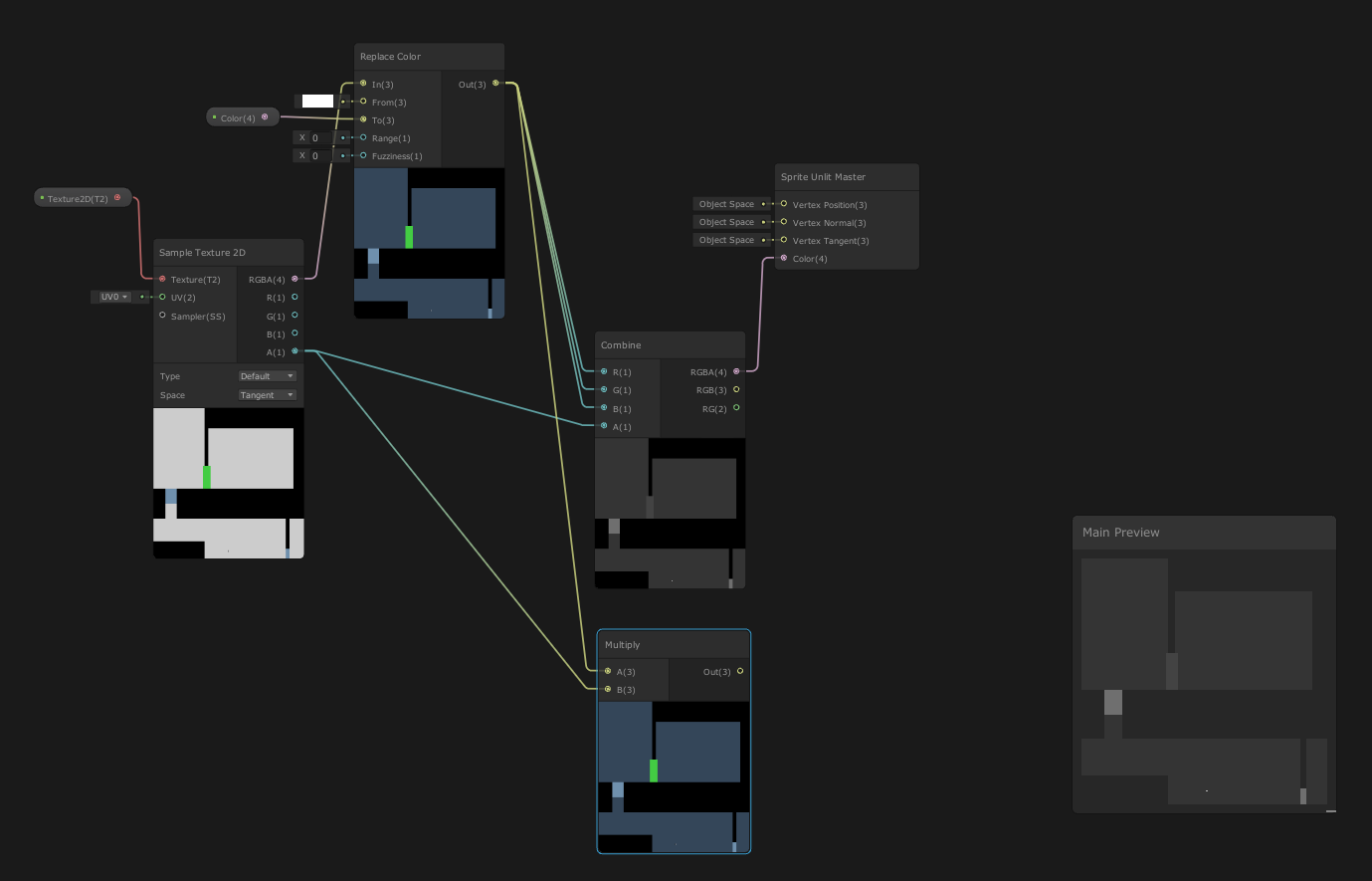
the mult node at the bottom is jost to show that the alpha is not working when I try to do it via mult
ok this is really weird, I just noticed that it only up black in the game window... it works as intended in scene view

I have had an issue before where something worked in scene view but not in game view. The solution ended up being in the different graphics spaces. If you think it would be helpful I can go into more detail. I dont know if it's related to your problem or not.
no idea honestly
at this point though, I may just give up on using a shader to color it, and color it manually with a simple Sprite.Color
jsut means I have to put everything that isn't white on its own tilemap
I'm reading through that long page from cyan that was pinned
Where?
Explains how shader code (ShaderLab & HLSL) is written to support the Universal RP
I read like 90% of it but I'm just not understanding it
I can only really understand the basics
Hey that's a really great source though
I don’t get it
Basically the difference is birp was using CG shader language, while SRPs use hlsl. Both are very similar, but CG is deprecated since 2012.
What dont you get ?
It's turning greyscale here because comnecting a Vector3 output to a Vector1/Float input truncates the size of the vector (only uses x or red value) rather than each colour component.
You need to use a Split node (on the Replace Color output)
Alright so everything past Depth test is what I don't understand
Explains how shader code (ShaderLab & HLSL) is written to support the Universal RP
there's a bit I do understand past that but most of it I don't
Hi,
does anyone know a tutorial on how to convert Standard shader to URP?
there is a very cool free asset for vr that is the only one of its kind in the store, that only supports standard shader, but we are using URP
I'm doing a simple test run VR project, and I believe this asset is essential yet very simple
where can i find a list of all possible matrices in HLSL? like float4x2, float4x4, etc
Afaik you can have a matrix of any scalar type, and row/column sizes between 1 and 4
https://docs.microsoft.com/en-us/windows/win32/direct3dhlsl/dx-graphics-hlsl-matrix
also i've read just now that some platforms only supports square matrices
I think that's because glsl might only support square ones. Not sure if it cross-compiles to an appropiate size automatically or not though
I trying to come up with approach of how implement MainTexST with altalsed sprite. And i think that i can just use 2 MainTexST, one to locate texture part on atlas and second one to really make tilling and offset for located rect
so i was thinking about float4x2 to avoid extra compute buffer copying
ooh, ok thank you, I'll give that a try
I actually got a different iteration of the shader working, but I think I'll go implement that solution just to put it in my memory
hi, one of my textures in my shader is showing up sideways - any ideas?
its a shader that replaces the texture on cliffs with a cliff texture (the A Short Hike kind of thing) and the texture is right side up on one side and 90 degrees wrong on the other plane.
that definitely did work btw!
https://i.imgur.com/g0dMfom.png
thanks so much
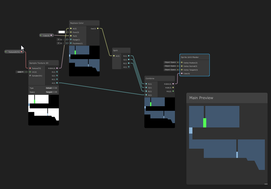
im making a custom skybox shader
and i cant find a guide on adding the sun and matching its rotation with the directional light
if anybody's got a good tutorial send it over pls :3
Can try this one : https://jannikboysen.de/reaching-for-the-stars/
Can alternatively get the main light direction with a custom function, something like Out = GetMainLight().direction;
figured it out .zy needed to be .yz
hello guys
I want to try making a shader that breaks tiling repetition (from the Blender donut guy's video)
to do that, I need to rotate uvs for every tile independently (mesh segments, for now just single square faces)
how can I achieve that using the shader graph ?
I can also rotate the uvs in the mesh generator, would that be a better solution ?
nvm, figured that part out
works exactly as I wanted, except some weird black dots appearing

they seem to appear only at the corners of the faces, any idea what could cause something like this ?
some bug in the code/calculations
probably a divide by zero or something or a sqrt of a negative number
nothing like that in my nodes at a glance, but i'll try to play with the numbers maybe

I think I know what might be happening, fraction returns 0 at the edges, that breaks the center calculation and rotates around the wrong point
I guessed it right, solved it with putting tile centers into zw of the uv0, couldn't figure a way to distinguish tile edges purely inside the graph
didn't expect that uvs with all corners having the same value would also be interpolated
had to trunc and add .5, .5 to get rid of that
feels kinda hacky
shaders.jpg
anyone have to share Shader stripping tutorial, as I am stuck at making list of needed shaders orther than creating shadervariants file.
continuing with the tiling shader
one other technique he uses is some sort of edge distortion for tiles
can you do something like this without touching the geometry ? it looks like uv distortion, but it only affects the seams

Something like this might work :
Position (World) -> Swizzle (xz) -> Add some noise -> Posterize
-> Fraction that result for the "UV" port on a Rotate node, "Center" as (0.5, 0.5)
-> Floor that posterize result -> Random Range -> into "Rotation" port
Then use Rotate in "UV" port on Sample Texture 2D
thank you, can't even tell what's happening there at a glance, but I'll try it rn 👍
it looks like it distorts the whole uv map, but I'll play with it and see if I can get it to work only for the seams

May need to lower the strength of the noise (multiply by a small amount like 0.02)
I'd also -0.5 before that to center it
I can see that it produces the shapes that do look exactly like those in the video, just need to adjust it somehow, my initial guess would be to scale my uvs differently
thanks for the help, the general idea does seem to replicate that effect ❤️

Is there a way for me to get the positions of every light source in my scene in the hdrp shader graph?
I am making an atmosphere shader and am using this to make a fake direction but I have multiple light sources that I need show my shader for.


hi i wanna add decals but there is no option for that here
there should be a render option here but mine dont have
tried to make a swaying grass shader and ended up with this abomination lmao
the heck am i doing wrong? is it a scale thing?
the shader is as simple as it gets i think

To me that looks like a space issue. Like something that's being calculated based off view space (I think) when it probably should be in object space
the weirdest thing is that it works on the shader preview
wtf it works if i see it through the camera but doesnt work in Scene mode
I'm following the Toon Shader Tutorial from NedMakesGames I finished the additional lights section but it seems that it is skipping most of the shader itself and I can't find where this is happening, my guess is in the HLSL file but I wouldn't know where... anyone able to help?
the main light works fine with the ramp texture and specular highlight, while the additional light (the lightest gray part on the sphere) doesn't blend in with the main light, gets cut off by the main light and does not render the ramp texture nor the specular highlight.

Make sure to enable "Always Refresh" on Scene view View Options toolbar to make sure the shaders update all the time
Anyone knows how can I remove atmospheric fog from specific objects?
Sorry for the perhaps silly question, but is there any way to interpolate more than 2 things using the same value?
basically I'm trying to do an interpolation from 0 to 1, but with sections of 5 images.
0 being the first image
0.25 being the 2nd image
0.5 being the 3rd image
0.75 being the 4th image
and 1 being the 5th and last image
is there any way to do this?
yeah I did this recently actually
with matrix4x4s
i dunno about... images really but ideally the 5 things are in an array/buffer
basically the way I do it is like:
float t = whatever;

// find the nearest two values to the interpolant
// if t is 3.4, then low is 3 and high is 4
uint low = floor(t);
uint high = ceil(t);

// for example if t is 3.4, then t - low gives us 0.4
float portionBetween = t - low;

// interpolate between the two nearest values
result = lerp(data[low], data[high], portionBetween);```this requires t to be 0 - 4 though, not 0 - 1
so maybe just a t = t * len(data); at the start to rescale it appropriately
if I have 2 different shader graphs that I want on 1 object, do I have to make them into subgraphs and put them both in a new graph? or is there an easier way
If you want two different effects you have to merge them in the shader
ok thanks
Turn it on

this is probably the simplest thing ever but i have no idea how to look it up like at all bc im not familiar with the terminology, but how would i make a material thats just a solid color without any shading whatsoever
just use an unlit shader
I think there's an unlit color shader built into every render pipeline
if not, it's a very easy shader to make/write
I created a basic color changing shader with shader graph, but the material from the graph is pink. I've upgraded the material to URP and set up the URP asset in the settings, but the problem persists. Any idea what could cause this?


How do I generate smooth normals from a pixelated texture? I know the answer has something to do with making the texture blurry and using Distance Fields
if this is my input, how do I make it so the normal map I generate from this is not pixelated mess and looks rounded and smooth

ideally the end result would look something like this? except without needing a texture map 4x larger

I know it can be done because thats how fonts do it

this looks like it could help
https://weesals.wordpress.com/2021/05/11/generating-sdf-signed-distance-fields-in-unity/
Signed Distance Fields is what you are after
I’ve built a package for generating distance fields from texture masks in Unity. It works in several modes: A) Append “+sdff” to the end of a filename to generate an SDF from its …
Thanks ill check that out
Hey do you guys know any good tutorials or exercises for learning how to use shadergraph or shader coding? I'd like to reach a point where I understand the concepts behind shaders rather than understanding niche tricks.
if you are into learning how shader work under the hood this video has a good overview
https://www.youtube.com/watch?v=kfM-yu0iQBk
this is more shadergraph stuff
https://www.youtube.com/watch?v=nDsTBk6eano

Welcome to my three part lecture on shader coding for game devs 💖 I hope you'll find this useful in your game dev journey!
If you are enjoying this series, please consider supporting me on Patreon!
🧡 https://www.patreon.com/acegikmo
00:00:00 - What are shaders?
00:03:00 - Case study/screenshots from FFXIV, Overwatch & more
00:37:42 - The Struc...

In this Unity tutorial I go over some of the fundamentals of Shader Graph. How to sample textures, play around with colors, distortion, PBR, etc.
Shader graph is used with URP and HDRP, but the principles I show also apply to Amplify Shader Editor or any other node based shader editor.
Disturbulance Texture Pack
https://gumroad.com/l/mlUGC
Pr...

my sub surface scatter shader isnt working right at all

In this tutorial I'll show how I made a fast, lightweight shader for mobile devices using Unity's shader graph.
The shader is based on articles by John Austin and Alan Zucconi, which were themselves based on a GDC paper by Colin Barré-Brisebois and Marc Bouchard.
I followed this tutorial to the letter but my result looks nothing like theirs
How do I get it to look like theirs?
im just taking some notes on how i can remove if statements from my HLSL code and ive come across using lerp(A, B, step(x, y)). But if i wanted to make this into a function for slightly better readability what would be a good name for it? im sceptical to naming it somethingIf, but not too sure what else could be a good name
or maybe i should just avoid making a function all together and just add a comment whenever i use it instead?
i've also found this post saying step is basically an if statement. so is this method any good then? https://forum.unity.com/threads/using-if-else-statements-in-shaders-how-complex-is-bad.602902/
Unity Forum
Hey guys,
So I think I found a good solution on how to do dynamic tessellation on my snow shader. The issue is that it likely involves an if-else...
there is also this saying it does not count as branching https://forum.unity.com/threads/step-vs-operator.604873/
Unity Forum
Hi everyone,
I know that, for performance reasons, we should avoid if statement in Cg. So as one does, I use the step function quite a lot, but I've...
But everything is fine in the editor...


If these are errors that happen in the build, you need to be sure you're including the shaders in the build or they will just be stripped
See https://docs.unity3d.com/Manual/class-GraphicsSettings.html Always Included Shaders
thx
Honestly the whole "avoid if statements" is an outdated thing. It doesn't necessarily mean the shader will even branch. But if it does, branching is usually fine as long as pixels take the same side, like using a property.
If you really want to avoid branches, think you can add [Flatten] before the if - or use a ternary instead (condition ? a : b). Should be slightly better than using lerp & step.
ah ok, thanks!