#archived-shaders
1 messages · Page 246 of 1
In shader graph, how do I use a branch to check if a texture property does have a texture ?
I'm trying to blend overwrite two textures (to apply the second texture over the first texture, kind of like a decal) but sometimes, there is no second texture

better to use a placeholder "no-op" texture, which I believe unity will insert automatically.
no-op texture ? How do I do that ?
What I mean is
structure your graph in a way where if it's just a pure white texture, it won't affect the final color
oh, if the second texture is not filled, it's pure white ? I didn't know
you can insert a default texture for any exposed properties
you can make it pure white
or pure black
or whatever you want
I have to say, not a big fan of having to add a fully transparent png as placeholder in the shader graph. Seems kind of overkill.
I guess I'll keep my current solution which uses a "HasDetail" bool which is calculated at runtime then. Too bad I can't do it easily directly in the shader graph
Wait, while reading your reply, there's still one part I'm missing.
This, how am I supposed to check if it's pure white?
sounds like you don't want pure white
you don't need to check anything
you just set up your blending such that the placeholder texture is a no-op
if your blend is like c1 + c2 then a fully transparent image will be a no-op
if it's multiply then a fully white image will be a no-op
if it's darken then a fully black image will be a no-op
or rather you set up your placeholder texture such that the blend you are using is a no-op
ok, but with your solution, c2 has two possible values. Either the one filled manually, either the placeholder right ?
sure
So how can I tell shader graph to use the placeholder instead of the unfilled texture then ?
sry... i changed my bias settings as the doc suggested... but it doesn't help

Is there such a thing as early out in shaders? Like if I have to iterate over 256 matrices and I can use a sphere range to early out of it
The code runs on the instanced setup phase, whenever that is
#pragma instancing_options procedural:setup
void setup() {
code
and also... the shadow itself looks normal... if i return float4(shadow, shadow, shadow, 1)

(i probably should mention that earlier...
and the diffuse value and specular value look normal without the shadow, but the problem occurs when they are put together
Im so close to getting what I want , I am using the dissolve+forcefield brackeys tutorial so that when an object intercepts, it dissolves a portion but im getting the opposite, it only shows the model where they intercept

I feel so close, that i can taste it, but if i add a minus one node nothing shows at all
i'm having a lot of trouble with canvas rendering
I'm trying to control the look of some UI elements with shader parameters
but for some reason I can't seem to figure out how to make separate material instances for each UI object

this feels like it should work but it says mat is null when I run it
in versions where it does work, it changes all objects with a given material rather than just an instance of the material
Bug fixed... I deleted the fallback and it has gone normal.... dont know y...
but thx 4 ur help, thx a lot
There's a [branch] attribute, but frankly you MAY not get any benefit from it.
Let's say your "wave" has 64 GPU cores dedicated to it. And each of the 64 cores checks your condition to decide if it will take the true branch or the else branch. Well, if you get really lucky, ALL cores will take the same branch, and if that is your early out you've hit the jackpot and can bail out.
BUT...more likely, unless you're branching on a uniform value like a material setting or shader global value....some cores will take one branch and other cores another.
What isn't obvious with GPUs is that all these cores in the wave share the same program instruction counter so what really happens is that all cores step through all instructions, including the loops, and some are masked off if they're not in that branch, and others are active. So you end up incurring the cost of BOTH sides of the if/else.
And that's why everyone gets paranoid about if's in shaders.
well, there is no 'else', it's just an early out. Does it mean every core waits the worst case core?
If it's an out it's a return...or a jump around. But either way, chances are that yes...every core waits for the worst case, because they're all looking at the same instruction counter...that's all they can do, but they're masked off if the condition doesn't apply to them. So they wait.
well, it seems to work anyways
My shader have options for 1, 2, 4, 16, or 64 wind zones, where each blade of grass checks if it's inside them and then applies the wind if so
previously, before the early out, with 5 wind zones in the map, setting 4, 16 and 64 were very different, now either setting seems to be the same, GPU usage wise
I'm not surprised that they're the same.
But...the # of zones would change the speed linearly I'd think....I mean as a multiple of the # of zones.
Since you're doing up to 64 zones, you might be able to benefit from an acceleration structure of some kind, like a BVH tree. Might be worth googling.
yeah, that's the next level of optimization, but I won't be using more than 4 for a long while, and with 4 there is little impact
Talking about matrices... I want to try to simplify some stuff
I have a vert that is the world position
and a radian angle for the X? (quite sure it's the X) axis rotation
Explaining the same issue with other words:
Currently I create 3 matrices (two rotation matrices and a translation matrix) and then use finalmat = mul(mat1, mul(mat2, mat3));
I think that I can simply create the resulting matrix to avoid two matrix multiplications, but I am not sure where each value goes.
I've managed, but it's one hell of a mess
Just double checking, but as ugly as this is, this is better than 4 matrix multiplications, right?
const float cosangrad = cos(anglrad);
const float sinangrad = sin(anglrad);
const float cos15 = cos(1.5708);
const float sin15 = sin(1.5708);
unity_ObjectToWorld._11_12_13_14 = float4(FinalRot.x * sinangrad * cos15 + FinalRot.y * -sin15,FinalRot.x * sinangrad*sin15+ FinalRot.y*cos15,FinalRot.x * cosangrad,pos.x);
unity_ObjectToWorld._21_22_23_24 = float4(cosangrad * cos15,cosangrad * sin15,-sinangrad, pos.y);
unity_ObjectToWorld._31_32_33_34 = float4(-FinalRot.y * sinangrad*cos15+ FinalRot.x*-sin15,-FinalRot.y * sinangrad*sin15+ FinalRot.x*cos15,-FinalRot.y * cosangrad,pos.z);
unity_ObjectToWorld._41_42_43_44 = float4(0, 0, 0, 1);
Depends on the # of times you have to do it. But in general, yeah. GPU's are built for matrix math though, so it might not be too bad.
In fact, Unity's UnityObjectToClipPos macro does two matrix multiplies. First object2world which requires the object's unique transform and then world2clip using the camera's "general" view/projection matrix. lol. But the two multiplies are hidden behind the one macro/function, so you don't notice it.
Anyway, attached is a cheat sheet for matrix info if you're interested at all (Looks like you already have it worked out). From here: https://answers.unity.com/questions/1359718/what-do-the-values-in-the-matrix4x4-for-cameraproj.html?childToView=1359877#answer-1359877

Unity is the ultimate game development platform. Use Unity to build high-quality 3D and 2D games, deploy them across mobile, desktop, VR/AR, consoles or the Web, and connect with loyal and enthusiastic players and customers.
Hiii,A noob question:What's the w value of the screen position node?
A depth. I think it's the clip space W component and it might vary between D3D and OpenGL. I don't recall what Unity does. But you end up with the perspective divide value, IIRC.
A big post explaining everything about Depth : Depth Buffer, Depth Texture / Scene Depth node, SV_Depth, Reconstructing World Position from Depth, etc.
i have a problem with a plane. i deactivated backface culling for the plane , i can look trough it but the camera is never cleared for that plane. what can i do?
ok it has something todo with unichan and my renderfeatures. only happens with unichan frontface mode
maybe its because unichan uses lightning ... you should see trough the entire wall, but that happens only if you move to the corner and the camera doesnt clear for that plane. the blur come from pp (im trying to figure out how to get rid of that).

screen space ambient occlusion is causing this 😐
do time nodes with tiling and offset work differently in HDRP? ive created this simple moving noise texture, it moves inside of the shader graph preview and the preview in the inspector, but it doesnt move in game or in the scene view

i follow a tutorial for it, but they used the URP
One problem here is that in editor the Time variable keeps increasing as long as the editor is open, beyond floating point accuracy so using it as offset eventually stops giving any usable UV values to the noise node
You could test if that's the issue by placing a Fraction node between Multiply and Tiling and Offset
it didnt have any effect on it moving in editor, although that issue may have come up at some point
im thinking it might be some setting on the Graph inspector considering different pipelines have different settings

although at this rate ive tried everything i can think of in terms of setting combinations
im going to make a new project and try to replicate this material to see if it is an issue with project settings
Well, before that you could try offsetting a random texture (instead of noise) by a specific value (instead of Time) to confirm that you can infact display textures and offset them

Not sure what I'm looking at
Also, when you test make sure to use a default cube or sphere for testing as well
The shader you're using requires valid UV maps on the mesh that it's being used on
i dont really know how to show what a moving image would look like in a screenshot, but its just a random texture that i threw in instead of the noise
im just using a plane
Ah, now I understand
doesnt offset on a normal cube either
Huh, strange
Check the value of DissolveSpeed property on the material

ok ive remade the material, checked the project settings over, and even built my game, nothing has helped
im going to try having a script handle the actual texture moving instead
How do i turn off material's shade ?
hey so I'm new to shaders in Unity, and so I was a bit confused when I made a standard surface shader and it was totally pink. Is there something else I need to do? (on version 2021.3.5f1 URP)
URP does not support surface shaders (currently at least). There are some docs page that explain writing unlit shaders (https://docs.unity3d.com/Packages/com.unity.render-pipelines.universal@13.0/manual/writing-custom-shaders-urp.html) and I have an article (https://www.cyanilux.com/tutorials/urp-shader-code/)
But the recommended way to write shaders in URP is probably to use Shader Graph. The "Lit" graph template is similar to that of a surface shader (providing outputs for albedo/base color, alpha, smoothness, metallic, etc)
ah dang I was hoping to learn to write shaders
well thanks anyways
also are you Cyanilux from the BlitRenderFeature? its incredibly useful tysm
Does someone know how this game achieved this?
Basically, this game which uses I believe Some Unity 5.2 version, had a skybox that only used 1 texture as if it gets tiled in the sky, and they also applied a "Emission" texture to it
is this still possible?
achieved what?
here
I can show a ingame screenshot of it
I thought you were going to

Its hard to fully depict it, but the sky is more of a flat plane on the top, not a cube like normal skyboxes

It looks like the sky never ends, and im trying to achieve a similar effect
Can you just put a big plane up there with the material you want?
That was what im trying to not do
Only thing I could find in the game using some tools was 1 material "standard" for the emission texture
and the sky itself? It seemed like it was a 6sided skybox but i have no idea how they made it look like that
Actually, it seems now to me
that it might be a procedural skybox
because of the horizon of the edges
You can still learn about GPU's and shaders by starting with the built-in pipeline, and once you get that covered (there's tons of info on the net because it is older) you can migrate to the newer pipelines like URP. Just 2 cents.
But yeah, does someone have a idea how to achieve that?
how can i avoid the overlappings when using depth test with render feature

make some shaders culling back and front maybe?
Guys, I was making a shader with pixelated depth based foam, however, I realized that depending on the camera angle, the pixels cut in a triangular shape, is there any way I can remove this and make it pixel-perfect?
doesnt the triangles exactly match with the editors wireframe view?
maybe use the pixel world coordinate modulo some value in order to decide whether it should be cut off or not? i'm not sure how you are implementing it so im just guessing
nope
we really dont know what "pixelated depth " means
are youre using view-direction node?
basically I want to do this only in pixel perfect, so I just pixelated the UV to make it square, I don't know if it's the right way to do it though

but as I showed, the pixels are being cropped depending on the camera angle
how? posterize node?
doesnt look like it
-> scale down uv

but like I said, I don't know if it's the right way
looks good, as mentioned, you can use posterize-node for this
I took a look now, I didn't know this node existed, I'll try with it to see if it solves
it does exactly the same here(no difference)
show the rest of your shader

since you dont have any view direction node, or something like that , i dont think its due to the shader
Yes, that's the problem, the problem is with the camera I think, but I have no idea why it's making this cut
nut surewhat the node to right is
the Depth Fade ?
below
ah, it's just a node to move the texture over time, I'll show you

yap. look at your settings...i guesss....
do you think there is something wrong?
maybe shadows..
maybe its lightning because of the faces (not enough vertices)
def. looks weird
You can render any kind of environment out into a skybox texture if it stays static
So it's possible they made a huge plane of clouds with a glowy horizon in 3D modeling software and just printed a skybox from that
though doing that in shaders isn't an impossible task either I don't think
I'm putting this shader on a plane, do you think that's the problem? missing vertices?
in that case no
but its not your shader
well I'll investigate what it may be for now, then if anyone else knows how to solve it, I'd appreciate it
So your telling me, they put a flat plane in the sky and made it have that texture?
I mean, i did look into the game files, it was a skybox for sure, i just dont know how they applied the sky like that
It looks like a "procedural" one because of its horizon kinda
That's one way to do it
It's not really possible to tell if it's procedural or not just by how it looks
Unless it moves in a way that's impossible for a texture skybox, or if the resolution is so low that you can see individual pixels
You could make a procedural skybox in blender and render that to a texture skybox, if you wanted to, and it'd look much the same
It doesnt move
it stays static
its gotta be a skybox then since I cannot visually see the thing moving, neither if I fly super far up using noclip to get it
That wouldn't give you a clue either
Both procedural and texture skyboxes are usually rendered at "infinite" distance away, so they never react to change in viewpoint
No I meant the plane thing
it cant be some plane for sure, but its a skybox
not sure what type
It doesn't have to be a "physical" plane to be a plane
Indeed
And just because procedural skyboxes are capable of moving or changing in ways texture skyboxes are not, not moving is not proof that it isn't procedural
Yeah i never said that
I just meant it isnt a "plane" or a physical mesh thats just scaled super high
It just confuses me how that skybox really works
I can look at it again and disable all the pfx effects to get a better look at it
Point being it could be either
yeah
Ill check it rq
@grizzled bolt

it doesnt move at all with me moving around
The game was like Unity 5.2 i believe?
its basically just what i did with the skybox 6 sided
but the problem with mine is
That it isnt as "low" as their skybox
^still wondering how to get rid of the spots(overlapping meshes of the same layer) ->stencil or depth??
maybe mesh.combine?
is there any way to compare the depth between one object on another without using the camera?
basically what I want is to get this water depth but without depending on the camera, I want it to be a fixed value, regardless of where the camera is, is there any way?

can you define what "scene depth" means in the absence of the camera?
and object depth
right now both seem defined by the camera
basically I want to get the information of what's under the mesh where my shader is and apply an effect, but without depending on the camera position
I put this earlier, I'm trying to make a pixel-perfect water foam, but as it's getting information from the camera, the pixels are distorting as the camera moves, I want it to be a fixed value
maybe show your shader

hello~
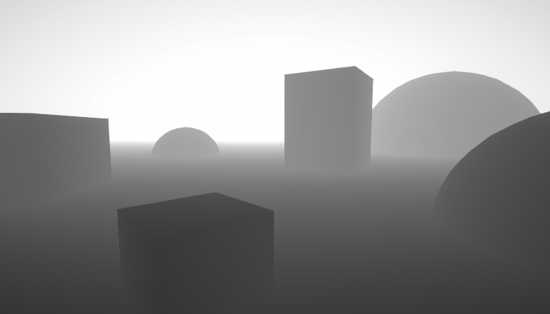
been working on convertin a spherical mask shader script from a utube tut to shader graph for a little project and was running into some weird behavior that my small brain cant explain
CONTEXT:
so the shader script is as follows
fixed4 c = tex2D(_MainTex,IN.uv_MainTex)*_Color;
half grayscale = (c.r+c.g+c.b)*0.333;
fixed c_g = fixed3(grayscale,grayscale,grayscale);

half d = distance(_Position,IN.worldPos);
half sum = saturate((d-_Radius)/-Softness);
fixed4 lerpColor = lerp(fixed(c_g,1),c,sum);
as i understand, the script makes a grayscale version of the main text
then it gets the distance of the current fragment from the center of our circle stored in _Position [not to sure if my understanding here is correct]
it divides that distance by our the negative of our softness factor(which is meant to soften the edges), this inverts our mask as well
the saturate function clamps the result of the last step between 0 and 1 and we use the result to interpolate a color between grayscale and actual color
ISSUE:
so i dont need the edges to be softened so i removed simply changed line 6 to something
half sum = saturate((d-_Radius);
in my head this means the mask is being inverted but the edges wont be smoftned
however this still gives me smooth edges while using the unmodified code but a Softness of 0 gives me hard edges. Shouldn't division by 0 break the code?
TLDR:
in the code block what exactly is the -Softness doing, how is it actually softening the edges
THE VIDEO IN QUESTION [TIME CODED TO DEMO OF FINAL RESULT]
https://www.youtube.com/watch?v=sJFu_sdLBy8&list=PL3POsQzaCw52iu1_P6CnM7oTctPuPu2MV&index=3&ab_channel=PeerPlay
Part 2 of the tutorial series on how to create a spherical mask shader in CG language, within the Unity Engine.
Created by Peter Olthof from Peer Play.
Support me in creating tutorials by becoming a patron on my Patreon and get access to the full source code of all tutorials.
http://www.patreon.com/peerplay
One time PayPal donations are also ...
hi how can i turn off material shader?
Wdym? There's no material without a shader. A material is just a set of data for the shader to use. If you "turn off" the shader, nothing will render.
Im baka
I mean gloss
Like wood object
Depends on the shader in use. If it's the standard one, that would be the specular+metallic settings.
In urp the property is called Smoothness it seems.
hello, just wondering if custom shaders are affected by post processing, since my grass shader isn't really reacting to the bloom i'm adding. i'm using URP.
AFAIK shaders and post processing have nothing to do with one another, shaders draw triangles on the screen, and post-processing does stuff with it afterwards. Your grass material should have a HDR color with an intensity higher then set in your PostProcessing->Bloom volume settings. My guess is that your grass does not have HDR color, so add that to your shader and increase the intensity and it should probably work.

alright thanks, i'll give it a try.
_Radius along with _Position (center) defines the circle (mask).
_Radius is a constant/uniform value in the frame.
d is the distance of the pixel to the center, so it isn't constant it varies by pixel. I'm sure you already know all that, but it's background info.
Thus, anything inside the circle has a negative result in (d-_Radius). This will come into play later since the sign needs to be reversed due to the order of the subtraction operation. So PP divides by a negative value, making a positive result, essentially reversing the sign. IDK why they didn't just do the subtraction the other way around and use positive softness, but it doesn't matter, maybe there's a reason and I didn't go back and watch part 1.
The saturate clamps to 0-1 range, as you state. So any pixel with a distance outside the _Radius ends up being a positive in variable "sum". Think of the edge of the circle as a ZERO point and inside is negative and the outside is positive. So the result of "sum" is +/- around that zero boarder. And the division by the negative reverse the sign, as we've said. Saturating the values clamps things to below 0 and above 1 so wildly large absolute values are irrelevant.
But what does dividing by softness do? It shifts that boarder! If the circle's radius is a 1, and you set softness to .5, you've changed the result of "sum" to be double of what it was (dividing by .5 makes it 2x bigger). So distances from .5 to 1 will now be >1. But remember it's still camped between 0 and 1 in the next step. This has the effect of making the softness band change more quickly.
Grab some paper and use some sample values.
Dividing by 0 is bad, and it really shouldn't be done. So you should ensure that Softness isn't zero. I'm not really fond of the method being used, but meh.

why is my texture being shown so weirdly?
when I don't use the shader but rather a normal material it works fine
ty so much! i have one last follow up question, I understand that division by zero is bad but to understand why i can get hard edges when smoothness is set to zero, is my assumption correct that unity instead of dividing by zero unity divides by a really small number so the sum becomes very large which in the enxt step is clamped to one. This means its basically acting as a step function. Would that be correct?
Based on the above I edited the last part of the graph to something like the following
(note: im using shader graph but sending pictures of that would be hard to read so ive done my best to translate it i apologize for syntax errors)

half sum = _Radius-d; //which gives us correct mask without need of negation

half mask= step(0,sum); //if value is greater then 0 it returns 1 otherwise it returns 0 which serves the same purpose as saturate
                        //without softening

fixed4 lerpColor = lerp(fixed(c_g,1),c,mask);
this seems to give the correct results in unity would this also solve the issues with the other approach that were bad practice?
@regal stag I saw one of your webpages explaining alot about grass, was super informative very pog
How can I access a variable inside a shader?
I'm doing the setFloat on matieral
material.SetFloat("Multiplier", multiplier);
And then I ques inside the shader i declare multiplier inside properties and use it
The propertie is working inside the shader but the script is not overriding it
_Multiplier ("Multiplier", float) = 0.5
Got it working
Thanks 😄
Another question:
Is it possible to use a circle sprite to cast a shader into the scene?
I now have a shader on my camera but I want a shader for my fire
Hello everyone, I was wondering if anyone could help me with something I'm running into. I am new to working with the Unity HDRP and made a shader, though when I put the material in transparent mode it looks very off. It is supposed to look like crystal and in the shader graph it looks fine, but in the actual scene it looks like the first image. The second image is when it is set to opaque. I am on Unity 2020.3.16f1.
Does anyone have any idea what I might have done wrong?


Here is the shader graph as well, sorry

The division by zero thing is probably implementation specific...don't count on all cards doing the same thing. Then again it may vary depending on Unity's shader compiler checks, IDK for sure.
As for making it not have any fuzzyness, if you just want a hard B&W edge vs color, all you have to do is use a ternary operator. Like
result = (d > _Radius) ? BW_Color : _theColor;
regards to 0: ah that makes sense thankyou!
regards to fuzzy: hmm i dont think shader graph has a ternary op but ill check
There's a conditional operation.
tysm
Hello,
I made a water shader according to the instructions. Once I applied the shader to the plane, everything worked, but I need to have different shapes (wrapping the walls), I used a meshCombiner that connects me to x planes exactly as I need. When I applied the shader, what you see in the picture happened. Is it possible to fix it via a shader, or do I have to work in that meshcombiner to ignore the following meshes, but only the circuit?

Hey im having an absolutely awful time with such a seemingly small problem. If someone who is confident with unlit graphics shaders and compute shaders can help me figure out my issue, Ill pay pal you 20 bucks.
Or cash app
You're using vertex offset to give the plane a wave effect right? The vertices of the four planes aren't welded together so the vertex offset causes an obvious seam. Idk what you mean by different shapes or how the mesh combiner works. One slower performing option is to generate the mesh procedurally via script
or post here for free
I just feel like its the sort of problem that will require fiddling from someone. And I've fiddled about all I can fiddle
Yes, I used vertex position to create waves.
The different shapes meant that if I have it as one plane, I can see the shader inside the object (so-called I want to create a wrap) and I used a meshCombiner to create a plane that has a gap in the middle of the object.
@fallow pivot If I am understanding the problem correctly, you do not want any gaps between the waves?
exactly
How are you getting the heights right now?
Via Vertex Position
Is that from a script or shader?
Shader
So basically are you getting the height (y position) from some calculation between the x and z position?

Oh man I don't know anything about visual-code shaders. I only know written-code shaders. My tip was going to be to set the x and z values to world position first, assuming they are still in object position (they are if you haven't explicitly said otherwise--at least in code) and then calculate the y value.
Is it possible to translate that to code? I will better understand it
so is an overlay a shader?
im trying to make black come in from the edges and cover the whole screen
sort of like when you die in super mario odyssey
Do you mean would you make an overlay with a shader? Or is there some tool in unity called an overlay?
I dont know, I do only visual
Ok no worries. That's all I can say though. Try and get those z and x values into world space
should remove any gaps
I thought that "Position" from Object to AbsoluteWorld would solve it, but unfortunately
"On the master node, you can right click and select 'Show Generated Code' and save the output to a regular shader file. The format will be different than usual shader lab shaders so I recommend checking the documentation for whichever render pipeline you're using." Saw this online
If you can do that, I might better be able to help you @fallow pivot
Otherwise, Vfx-and-particles might be able to help you
damn there is no way I can read that lol. Sorry I couldn't be more help. Good luck
pretext: I am in URP.
I have this particle effect which works perfectly in the editor scene during runtime but not in the game scene during runtime as can be seen in the following photos:


Now the "missing" particles (which Ill get more into in a sec) only are "missing" when any other **unlit **shader is being rendered (ie not culled out, or not disabled).
Now the particles are not really missing, they are just misplaced. If you look closely at the following image, you will notice a little dot in the distance.

Here is that dot close up in both game view and scene view. As can be seen the particles are not simply disappearing in game view, but are being moved. What's weird is that the particles are being moved in both game view and editor view. However, like aforementioned, the bulk of the particles are not disappearing in editor view--only game view.


To reiterate, these particles are only in the distance when an **unlit **shader is being rendered in the same frame as the particles. When you disable or cull out all unlit shaders, the particles act as expected--they are bulked where I want, and the far-off particles do not exist (in neither the editor view or the game view).
An extra note is that the far-off particles position is different depending on what unlit object is being rendered. For example, when I disable half of the burning logs, the far-off particles are placed high above the logs instead of horizontally far away such as they are now. I can find no pattern.
Now onto how I generate the particles: Their position is calculated using a compute shader (except for their initial position, which is calculated using the following c# script). Their color and model (which is simply an HLSL point) is created using a simple unlit shader. A buffer is created and data is shared from the compute shader to the visual shader through a c# script.
Here is the code for all three
C# script
compute shader (made into ".CS" so you can see it in discord computer version; normally ".compute" file)
and particle shader (made into ".CS" so you can see it in discord computer version; normally ".shader" file)
On a side note, discord's built in code coloring is very pretty. Never used that before
Unless we have the same GPU (3070 mobile) I imagine its 1024 for all GPUs, at least in unity
This is highly disappointing for me
OH FINALLY. It took two damn days but finally. So I will explain the issue for anyone curious
The issue was in the particle shader near the bottom. On the line that says
o.pos = UnityObjectToClipPos(float4(parti[id].pos, 1));
The issue here is that the function takes the position from object space all the way to clip space: so, object space through world space, view space, and finally into clip space.
This is an issue because my particles are already in world space and thus do not need to be converted into world space, and in fact should not be.
So the solution was to multiply my position by the view-projection matrix manually. So, that same line turns into
o.pos = mul(UNITY_MATRIX_VP, float4(parti[id].pos,1));
And now it works in both game view and editor view 🙂
Now what I can't answer is the behavior my particles were having. I guess multiplying by the model matrix (and thus into world space) twice would give unexpected results though.
Hi I have a really easy question but I'll ask in other channels as well just in case
Basically, I've got this slider in my material and so it is really easy for me to modify the value of the slider through code but I don't know how to properly animate it so you press one button and it changes values in a smooth way from the max value to the min value for example
If you have a piece of code that works well let me know please because I struggle with timers in c# and I don't know much about animation
@steady pike you can change values of materials with a function. For example let's consider a float from a material named mat: mat.setFloat("nameInsideShader", valueToSetFloat)
I'm happy to try and answer any other questions you have about it
@rich roost correct and it's working

but I'm gonna try a lerping method I got from the programmers channel
to see if I can make it smooth ;)))))))))
nice cat btw
@steady pike Try using delta time, and making resto a bigger number. So nivel-(resto*Time.deltaTime) in the setfloat function
mmmhh okay, that sounds more understandable than the forum
Resto will have to be pretty big probably

I tried this but it's still not smooth, it just jumps to a small value and if resto is too big it will just jump from max value(1) to min value(0) (ignore the comments, it's another solution I tried but it did the same thing)
I will keep trying hehe
What do you mean it jumps to a small value?
smaller*
sorry
completely different meaning, I used the wrong word
I meant smaller
it will jump from 8,03 to 7,56 for example
without showing the values in between
or at least in a way that i can see it because maybe it's too fast idk,
No worries. To me it sounds like you just need to keep fiddling with resto. Maybe there is another solution you will find though. Good luck 🤞
I'm figuring out positions in shader and was fiddling around with unity_ObjectToWorld
I want gray scale over half the screen

But the worldspacePos or playerpos isn't set correctly. The Shader moves much faster then the player
If I move right the shader moves like 100pixels while the player only walked 10 pixels


Hi is there a shader editor that will highlight issues as you type - like IDEs do for C#?
Does anybody have a flip/invert normals shader for URP?
Well seems there is paid ShaderlabVS Pro...
So, I've been messing around in HDRP by editing the shader generated from a lit shader graph. I've set the HDRP asset setting to Forward Only (also set it in the project settings), then tried to edit the color value in the shader in the Forward pass but nothing changed. I tried to edit the same in GBuffer pass and that did work. When I removed the GBuffer pass the material glitched out but removing the Forward pass changes nothing. It seems like it is still using the Deferred path, despite me setting it to Forward Only. Anyone know what am I doing wrong?
@winged rune did you figure it out?
@gloomy tendon while the editor may not highlight errors, if you click on the shader inside of the folder hierarchy, it will tell you where it thinks there is a syntax error. As for debugging the shader semantically, you just have to do that in the engine by playing around with values, colors, of whatever.
Also, I've preferred using something like notepad++ for shaders because it helps automatically fill in variable names, unlike Visual studio
I know VSCode has some plugins for writing HLSL shaders the provide things like code autocompletion and stuff
Extension for Visual Studio Code - Syntax highlighter for shader language (hlsl, glsl, cg)
Oh sweet, I'll have to look at that
@rich roost not yet
I need a little help. There are no targets to select for shader graph

To use shader graph you need to have URP or HDRP installed and configured, or be using an editor version that supports shader graph for built-in RP and then add a target for it
Thank you
https://www.youtube.com/watch?v=xMPFtxfL5Dk&t=512s&ab_channel=RobertThomson I recently saw this video, and I thought the effect at this timestamp was really cool. I'm not one who messes around much with shaders, but how do you think it would be done?
I made a cryptic puzzle game in a week about a developer who gets sucked into their own code!
I was challenged by Logitech to make a game in 7 days and record the process in a Devlog. I LOVE GAME JAMS. I definitely want to do more short videos like this, maybe collaborate with some other indie game dev YouTubers, who knows! Really had fun on th...

I doubt t anybody would know how to get the object bounds of a mesh in shader graph and use those values to set remap float values?
In UE4 you could use an "Object Bounds" node but as far as I know, no node exists for that in Unity.
Setting the values manually per asset is a bit shit, and not ideal.
Still you have to do that, either manually or via script. Unity doesnt provide that information to you automatically
@dim yoke that's fine then. As long as I know that's the only way and I can't do it in shader graph then fine by me.
Many thanks for the confirmation and help.
Stencils most likely
ty, after reading up on them i made a similar effect
the hardest part about shaders for me is just learning features
hello~ ive been trying to recreate painting with a hard round brush in paint inside unity, so far im stuck on how to actually get data to write to a texture. As far as i understand shaders dont have a concept of persistence so event if i can draw a circle like below i cant connect multiple circles to form a line. Any ideas on how i could go about solving this issue?(note: using shader graph)

in retrospect would it be better to deal with this in csharp?
Typically, you'd set pixel in a texture in c# if you need to optimize, jobs system or compute shaders are the way to go.
A regular shader is used just for rendering something once on the screen. It's not meant to output or persist data.
Although you might be able to hack something with render textures, but I think it's overcomplicating.
i see, hmm in that case i guess a follow up question would be how do i go about converting world space coords to texture space
You could cast a ray at the texture(assuming it has a mesh collider) and get the uv position from the hit data.
Or do some complicated math to calculate the position from world + object offset and whatnot. Don't even ask me how to do that. I'd rather choose the easy path.
oh snap ur right raycast can do that
thanks alot!
also one last question
this one is a bit of a silly one
but does urp affect the way compute shaders work? unity isnt really great about separating legacy items so i keep getting confused with we weird stuff
or are compute shaders independent of render pipeline since their just gpu computation commands
Not as far as I know. Compute shaders are written in hlsl regardless of the render pipeline. Might be wrong though.🤔
thankyou!
Now my turn to ask.
Does anybody know how sprite renderer-like sorting is implemented? Is it done shader side? Render pipeline side?
I want to implement a 2d terrain system with several meshes overlapping representing terrain layers. I want to avoid z fighting and have a specific order of them rendering. They need to be in the same position to avoid any potential "parallax effect" or any other issue related to z pos offset.
I'd use the sprite renderer, but it doesn't seem like I can use a custom mesh with it(terrain layers could be in irregular shapes,not just a quad)... Or can I?
the best way to paint on a texture is with compute shaders, they're super fast, or rasterize them on top with just a camera, I would advise against editing textures with c#
Especially applying the changes in c# script can take a while. Compute shaders are grear at modifying (render)textures
Hello, I am trying to use a simple shader on UI
I am new to shaders so idk if my problem is about UI or my shader code has errors
but the result I want works in editor
it does not work in play mode
here is my code: ```fixed4 frag(v2f IN) : SV_Target
{
//Round up the alpha color coming from the interpolator (to 1.0/256.0 steps)
//The incoming alpha could have numerical instability, which makes it very sensible to
//HDR color transparency blend, when it blends with the world's texture.
const half alphaPrecision = half(0xff);
const half invAlphaPrecision = half(1.0/alphaPrecision);
IN.color.a = round(IN.color.a * alphaPrecision)*invAlphaPrecision;
            half4 color = IN.color * (tex2D(_MainTex, IN.texcoord) + _TextureSampleAdd);

            half4 colorMap = IN.color * (tex2D(_ColorMap, IN.texcoord) + _TextureSampleAdd);

            color.r = color.r - colorMap.r;
            color.g = color.g - colorMap.g;
            color.b = color.b - colorMap.b;

            colorMap.r = colorMap.r * _Recolor.r;
            colorMap.g = colorMap.g * _Recolor.g;
            colorMap.b = colorMap.b * _Recolor.b;

            color.r = color.r + colorMap.r;
            color.g = color.g + colorMap.g;
            color.b = color.b + colorMap.b;

            #ifdef UNITY_UI_CLIP_RECT
            half2 m = saturate((_ClipRect.zw - _ClipRect.xy - abs(IN.mask.xy)) * IN.mask.zw);
            color.a *= m.x * m.y;
            #endif

            #ifdef UNITY_UI_ALPHACLIP
            clip (color.a - 0.001);
            #endif

            color.rgb *= color.a;

            return color;
        }```
I just copied default UI shader and added _ColorMap & _Recolor
Like I said it works in editor but doesnt work in play mode
can someone help me?
You can do a compute shader, or "just" use a "full screen" quad to draw to the texture. The texture itself IS persistent, if it were not we wouldn't ever see a GPU output anything, since it's all drawn to render textures (or directly to a hardware memory buffer).
So you'd make a full-screen (full-texture, basically) quad, and draw your ball with your normal shader and normal 2d qad mesh with the texture of the ball mapped onto it, outputting it all to a render texture. If you want to paint, you don't clear the texture between frames. Then you don't have to reinvent the wheel writing your own rasterizer in a compute shader just to figure out what pixels to draw on.
OTOH, sometimes you want to go after it in a compute shader, depending on what you're doing. Computations like blur or whatever might better be handled in a compute shader.
also let me add these: editor: https://cdn.discordapp.com/attachments/439354663079247873/992327108665815050/unknown.png
playmode: https://cdn.discordapp.com/attachments/439354663079247873/992327196997865492/unknown.png
original texture and colormap: https://cdn.discordapp.com/attachments/438387938947235840/992355151274852432/banner_monster.png - https://cdn.discordapp.com/attachments/438387938947235840/992355151509737522/banner_monster_color.png


Debugging: reduced to 1 line and replaced _MainTex with _ColorMap: half4 color = IN.color * (tex2D(_ColorMap, IN.texcoord) + _TextureSampleAdd);
https://cdn.discordapp.com/attachments/438387938947235840/992358701270839336/unknown.png https://cdn.discordapp.com/attachments/438387938947235840/992358701577027594/unknown.png


Somehow _ColorMap texture does not work in playmode, but I am sure it is selected?

Trying with another texture: editmode and playmode


So it zooms to bottom left somehow?
            {

                half4 color = tex2D(_ColorMap, IN.texcoord);

                return color;
            }```
removed all other code in frag method
still same resultTried same code with 2020 LTS version
it works
I was using latest LTS
Updated the test projec to lastest LTS, well it works in this version too
I dont know whats different in my project
facepalm
I forgot I added the icons to a Sprite Atlas
How can I make my shader work with sprite atlas?
Not too familiar with sprite atlas, but my guess would be using TRANSFORM_TEX macro on texcoord in vertex shader, if you are not already using it. (And add float4 _ColorMap_ST outside function)
thanks for the info
I am new to this so I will try to find some resources
if you have suggestion that would be nice
I am new to this and really having trouble finding documents/resources for this: how can I add second texcoord to this? ```v2f vert(appdata_t v)
{
v2f OUT;
UNITY_SETUP_INSTANCE_ID(v);
UNITY_INITIALIZE_VERTEX_OUTPUT_STEREO(OUT);
float4 vPosition = UnityObjectToClipPos(v.vertex);
OUT.worldPosition = v.vertex;
OUT.vertex = vPosition;
            float2 pixelSize = vPosition.w;
            pixelSize /= float2(1, 1) * abs(mul((float2x2)UNITY_MATRIX_P, _ScreenParams.xy));

            float4 clampedRect = clamp(_ClipRect, -2e10, 2e10);
            float2 maskUV = (v.vertex.xy - clampedRect.xy) / (clampedRect.zw - clampedRect.xy);
            OUT.texcoord = TRANSFORM_TEX(v.texcoord.xy, _MainTex);
            OUT.mask = float4(v.vertex.xy * 2 - clampedRect.xy - clampedRect.zw, 0.25 / (0.25 * half2(_UIMaskSoftnessX, _UIMaskSoftnessY) + abs(pixelSize.xy)));

            OUT.color = v.color * _Color;
            return OUT;
        }```
I mean I found this but I still dont understand: https://docs.unity3d.com/Manual/SL-VertexProgramInputs.html

Have researched a bit into this. Since the _MainTex is being atlased it is altering the UV coordinates of the mesh. Quads are usually like (0,0) bottom left and (1,1) in top right which maps the whole texture to it. When atlased, those are changed so that you sample only a section of the _MainTex.
But when you try to sample your _ColorMap (which isn't an atlas) with those same uv coordinates, it's super zoomed in as it's trying to take that same section rather than the whole image. You'd have to convert the UV coords back to the regular 0-1 space. There's an answer here which should work : https://stackoverflow.com/a/53821362

Stack Overflow
I have an issue, and i need help to resolve it.
I am try to colorize some parts of sprite dynamically by custom shader and additional textures as masks. It is not a problem and i solve it easy.
S...
sorry I am new to shaders so I searhed but couldnt figure it out. The vert method I posted up is default unity shader code. Do I need to calculate same way and add new value to OUT? If so how do I get the base data for my custom texture? Do I need to add new fields to appdata_t ?
As you see I have lots of questions you can suggest me resource instead of answers lol
Hey quick question
I have a nice shader with mask, but it's pretty expensive in terms of resources (I can barely process 100 of it in the same scene, theoretically).
Does the game/unity render objects that aren't in the field of view ?
let's say there are 100 of this shader object in the same scene but i'm only looking at 1 , the other 99 are behind the camera, would the device be rendering the entire 100 (clones) of it or just the ones in the field of view ?
Hello 😁
I have some 3D objects in a scrolling menu. And I want to hide them. Any solutions? I'm using URP
it does, but for camera cone
you need to set it up if you want to cut things behind objects
could you tell me more about this part or is there is a tutorial i could follow ?
just google for unity occlusion, it should show
mark this

then "windows>rendering>occlusion culling"
press bake and it should help a lot already
can fine tune with the project
thank you so much 🙂 @restive radish
Shader is working on editor but not on build. How do I even begin debugging why that might be?
hello~ this is a follow up to yesterday's question about painting in texture space during runtime. Based on suggestion by others I decided to use a render texture to output. Anyway Ill explain from the start:
CONTEXT:
Im trying to generate a texture that can be painted during runtime. The end result would be similar to how painting with a hard round brush is like in paint. To do this ive set up a camera that looks at a quad and outputs a render texture. That render texture is passed into a shader graph which samples and outputs to color.
ISSUE:
The shader works untill I enter play mode where all of a suddenly it sets the whole texture to black. Im assuming this is because the camera turns off or something when entering play mode for a split second which means the render output is black. Is there any way to get around this

this is all there is to the shader atm
hey, two quick questions!
Why is my scene color node not picking up sprites?
when updating from default to UPR, one of my cameras i use for outputting to a texture stopped rendering stuff behind other sprites (it only sees whatever sprite is on top and hides all others behind it, like occlusion culling), what's going on?
using URP
Please help, I am bad at shaders and I'm using the built-in pipeline. I'm getting this error.
oh I might have found it
Okay I couldnt figure it out so I will ask one last time and use single sprites for now. Here is the code: https://pastebin.com/ekDa2LBU I built on top of default UI shader. The problem is unity handles sprite coords for main_text when sprite is in an atlas. (https://docs.unity3d.com/Manual/class-SpriteAtlas.html) I need to do the same for my custom texture(_ColorMap) I couldnt figure out how to do it, I will be glad if you can help.
I tried to google it and I can't find what causes this error and would appreciate some help.
This is line 11:
slice("Slice", Integer) = 1
Hi, Im having a problem with compute shaders where it doesnt change all the content of the array and Im not finding out what Im doing wrong. I would really appreciate some help


the expected result in the kernel: noiseResult[id.x + id.y * _mapWidth] = 1;
Could you upload your code files (.cs file and .compute file)? When doing so, it would also be helpful if you could change that .compute file temporarily to a .cs file as you upload so I can view it without downloading
what are you setting your mapWidth and height to for the debug image above?
both 53
So are you not wanting there to be any zeros?
yes, I want the whole array to be modified
Just to make sure im understanding, for this test case, you want every index to be one?
yes, the value is arbitrary, just for testing
Yeah, it seems all correct math wise. Could be because you have mapwidth and mapheight as uints in the compute shader but you set them as float in the c# code. Just to be safe id even take them into the function as uints rather than just ints.
Another thing to note is that your threads go beyond the buffer size. The buffer size is 53 * 53 = 2809, whereas the threads go to 49 * 64 = 3136. Im struggling to think right now, but Im pretty sure that doesn't actually matter. Regardless, It's possible that trying to access those indexes of the array which don't exist is causing unexpected results. I know that it is good practice to keep your thread sizes the same size as the data you're working with. That being said, I would keep the map sizes some factor of 8 (since you have an 8 * 8 thread group) and remove the "+1" in int[] threadGroups = {Mathf.CeilToInt(mapWidth / kernelThreadGroupSizes[0]) + 1, Mathf.CeilToInt(mapHeight / kernelThreadGroupSizes[1]) + 1};. These two steps would keep your thread sizes and data sizes the same.
I will keep looking at the code for a little while and maybe experiment some. Hopefully I can give better answers
Also, Im not sure if you already have plans for this, but just in case, it would probably be helpful to match the data structure to the thread structure. In otherwords, your data is a one dimensional array, whereas your threads are set up as two dimensions. If you were to instead change your thread dimensions to be single dimensioned or your data to be two dimensioned, the math would be much easier to match. You wouldn't need to bother with the mapsize or the second dimension.
Wow, it was the data type. The shader doesnt have SetUint but it worked with SetInt
Well at least it works
yes, the ideal situation is thread nums = data num, but because of the geometry of other script its never gonna be a 8 factor size. Thats the reason of the last "if" of the kernel, to dont save the operations outside the array
Oh gotcha. Good luck on the rest of your project
Thank you so much for your help
Hello, is there an easy way to make the material stay in its original size and then duplicate itself to cover whole object instead of stretching?
I've tried doing terrain with 1x1x1 blocks but quickly figured it is dumb idea and will drag performance down a lot, then tried with probuilder to create 1 unit size faces so the texture will tile properly but it still doesn't seem optimal (not to mention I did create a lot of "inside" faces during that process 😐 less than with creating 1500 1x1x1 cubes tho so there is a little bit of progress), my other idea is just to do similar thing but instead of 3D objects just go with quads and make every wall a quad with 1x1 faces (meaning 7x3 wall would have 21 faces which seems still like a lot and feels really wrong). Creating a different material for each geometry piece, also popped into my head but then there is a problem that I've got 3 different textures of wallpaper (Middle, corner, side), or different tiles for the floor (a little bit roughed up, normal, minimal marks) so it doesn't feel as repetitive so it would still require me to add faces or new blocks to add those graphics. I tried some polybrush, but it also didn't seem like an answer to this problem, and well it seems pretty basic but I can't find a straight forward solution anywhere.
I've found https://docs.unity3d.com/Packages/com.unity.shadergraph@6.9/manual/Triplanar-Node.html and it seems like something that would help me, but I've never coded shaders so if there is a way that would allow me to skip it for now, I'd like to take it.
Or if there is a tutorial on how to do it properly (the texture work that is), or some kind of addon that helps with it, or maybe one of things mentioned before isn't as performance heavy as I think.
tl;dr
I want my texture to look like in picture attached without placing 100's of 1x1x1 blocks
(hope it's the right channel)

I tried to google it and I can't find what causes this error and would appreciate some help.
This is line 11:
slice("Slice", Integer) = 1
ok it's fine I just replaced the integer with a range, but I'd still appreciate if someone could tell me why that was happening
What Unity version are you in? Unity only has a proper "Integer" type in 2021+. There is an older "Int" type, but it's still a float behind the scenes.
Then yeah, it doesn't have the Integer type. Use Float/Range/Int instead
Ok thank you
Hey, I'm using a custom shader graph on urp and I have an overlay color field on my material that I'm using to make models flash. For some reason the alpha field of the overlay color doesn't do anything during play mode. In the scene view screenshot you can see the flashing gate is solid white, even though the alpha value is only 123. If I change the value outside of play mode the alpha blends with the texture just fine. Anyone know where the problem might be?


Immediately after sending this I learned more. If I change the value manually it works, even in play mode. Confusingly, the value of alpha appears to be the same as what I set in code, but it only works when I set it through the inspector.
For some reason using color32 in my code worked.
If you used Color before, that has a value range between 0 and 1
That is the most confusing part cause I was using values 0-1 when I was using Color.
hey, trying to display a texture with a parallax offset, but the parallax mapping node has a weird "rotation" effect depending on perspective, and the parallax occlusion mapping node straight up doesn't do anything
any idea how to fix it?
Is this a custom shader?
yup

for the record this is more or less the end result I'm trying to achieve https://twitter.com/MaximeCatel/status/1424415272677564423

Yesterday I was working on a shader representing Source from Divinity Original Sin 2✨Gonna make some variations !
Likes
718
at least the parallax part
Sorry I can't help with visual nodes stuff. I still need to play with it. But next time you should probably add the code/visuals from the get go. There's just no way someone could really help without it. Good luck
fair enough
I think this video will help you https://youtu.be/rlGNbq5p5CQ

Cracked Ice Material in Unity 3D
It all started when we saw the article „How to Build Cracked Ice in Material Editor“ (https://80.lv/articles/how-to-build-cracked-ice-in-material-editor/) by Ali Youssef (https://www.artstation.com/ali_y) which describes his approach to the topic in the UnrealEngine 4. Our goal became to mirror his material on Un...
Thanks
Is there any way to have 2 colors with different opacities in 1 shader?
It might seem like a silly question but for some reason I'm having complications with it lmao
You can have as many color inputs as you want
Yes I know, but I don't know if I'm doing something wrong, but if I change the alpha of the separate colors, nothing changes unless I have connected some alpha in the alpha node, but then it changes the alpha of all colors
It depends on what you're doing with the colors. ¯_(ツ)_/¯
i'm just trying to fade from one color to another based on the uv position, but i want the blue part to be transparent and the white part to be with maximum transparency
sounds fairly straightforward
what part are you struggling with
Seems like a simple Lerp
on making the colors have different alphas
Shouldn't be an issue. Maybe show your shader
As I said, I don't know if it's a bug, but if I change their alpha in the inspector, it's not transparent
Sure

like i said i shouldn't be having a problem with this lmao
you're ignoring the alpha
you're piping the whole color into Base Color
which is a float3
ignoring the alpha output from your lerp
Yes, but as I said, if I connect the alpha, it changes the alpha of all colors, not just blue for example


Maybe it's a bug or something
Ah it was a bug, I closed and opened the scene and fixed it, lol
anyway thanks for the help Praetor
so I'm pretty new to shadergraphs, shaders are magic to me and idk how any of them work and am trying to learn how to do stuff in shadergraphs - I'm trying to figure out how to add a 2d texture onto a skybox and have it move with the sun... I already have a circle for the sun moving but I just can't figure out how to put a texture there instead of a circle
I've kind of figured out how to add a texture along with the sun but it has this weird stretch effect the further up the skybox it goes along with being mirrored on the opposite end
http://grinboo.ru/data/screenies/2022-07/Unity_07-02-22_18.16.50.675.png
the further down the horizon it gets through the better it looks as it isn't stretched, still mirrored on the opposite end of the skybox though
http://grinboo.ru/data/screenies/2022-07/Unity_07-02-22_18.17.34.636.png
I'm thinking it might be uv related but I just can't figure out what I'm doing and google just ain't helping at least not with shader graphs lol


here's the upper portion for the texture to hook into the blend node: http://grinboo.ru/data/screenies/2022-07/Unity_07-02-22_18.13.46.109.png
and here's what I have for the sun shape: http://grinboo.ru/data/screenies/2022-07/Unity_07-02-22_18.13.28.383.png
the sun shape is just a circle without the texture part but I have it blending to show the texture in the same spot as the circle
if it helps at all, here's a pastebin for just the specific graph elements https://pastebin.com/h7Xz2j6A and here's the full shadergraph: https://drive.google.com/file/d/1Y6HQzHvISOASelYd9j9JHnZNDuNHg2XU/view?usp=sharing


sorry if that's confusing at all (or if this is the wrong channel rip), tbh I'm just kind of plugging stuff in/experimenting with it and hoping it eventually works how I want it to lol
The default Unity sphere has the input texture doubled and UV-sphere mapped, hence the doubling and "stretching" near the poles.
What you might want is to create a sphere with UVs mapped so that it uses only one texture across the whole sphere.
This is a UV problem and unrelated to shaders for now.
Ah okay, since it's a material to be used as a skybox I'm using a cubemap and whatnot, if I were to make a sphere UV would it just be as simple as applying said UV to the texture sampler? Or like, is there any way to just cast the texture onto the cubemap/skybox sphere?

wasn't quite sure where to go, but I'm having trouble making textures appear on this free 3d model of a bed I downloaded
where is gpu instancing?

Sorry, how do I get to that screen?
The shader needs to support it.
what kind of shaders should I build if I want do have a decent shader portfolio? I don't have a game that I could work on so is there some shaders that are good to have in your shader toolset?
is unity have shader node that same function like color ramp in blender
bakes indirect lighting from emission sources and annoying gap appeared. What setting is responsible for it?

the gap is on the edge between game objects
ok there is too much of minor parameters to take in consideration
hell this is awful

Any idea what is happening when I do graph like this + transparent surface

it get's very, very bright (around 2000-2500 color instead of 0-1)

that's unlit shader
are you using HDR?
yes
is there a way to figure out how big a pixel is to say, check the colour of the pixel at the uv coordinates beside it?
For instance, in Gamemaker Studio 2, you can get the texel size, is there a way to do that in unity?
What kind of use case is it?
I have a perlin noise function, and I want it to find what the value that it will return for the pixels surrounding it is.
oh hang on, is it this _MainTex_TexelSize
Are you still there?
Sure, but I doubt I'll be of much use here
Still, the better detailed your plan is the easier it is for anyone to offer advice
Yeah this should give you the texel size (.xy) and width and height (.zw) of the texture, iirc
ok thank you, I'll see if I can get it to work
As far as I know shaders can't really react to surrounding pixels, except in screen space with ddy, ddxy and ddx
But if you're not working in screen space it could be different?
ok thank you, I'll try this and maybe let you know afterwards if it worked
If this is HDRP I think there is a HD Scene Color node which outputs differently. Or can use an Exposure node. (I dont use HDRP but this is based on docs and what I've seen others mention)
can you link source? It will be easier for me to understand that
I mean where did you find it
Can Lerp between two colours, or Sample Gradient. Or Sample Texture 2D may be better if you need to expose it to the material.
Use a Saturate on the input to clamp values outside 0-1 range.
Sorry I just have one more question, how do I actually access that variable? I tried adding this to appdata float4 texelSize : _MainTex_TexelSize; but it isn't working.
It doesn't go in appdata. Define it as a global variable. So float4 _MainTex_TexelSize; outside the functions
Anyone seen accumulative rendering done before (for like motion blur, temporal effects etc)?
I'm trying to wrap my head around what the easiest/best approach would be
I basically want to render my scene a couple of times and merge the result together into one texture
I'm reading up on custom render textures right now thinking that might be the way to go but it feels convoluted for something so simple.
As for "render my scene a couple of times"...you can do that with a couple cameras.
As to how to merge...well...depends on what you're doing. But...render textures are persistent.
As to "it feels convoluted for something so simple"...what you described isn't simple, nor is GPU programming generally simple, so...expectations don't seem to be realistic in that statement.
It might be reasonably simple with just two cameras. But you'd have to describe WHY you're rendering the scene a couple of times, and what it is you're trying to do, in detail, to get more help on the "hows" of it.
@tender remnant
I'd like to do some simple temporal depth of field and potentially other temporal effects
I think I'm on the right track with the custom render texture stuff. But I'm stumbling a bit right now when trying to use the doublebuffered feature
Normally, temporal effects are done across frames, rather than rendering the scene multiple times per frame.
I'd agree that stashing the results in some render texture between frames is the way to go.
So in "frame 0" it might not have much effect, but meh, if you're running at 30 or 60 or more FPS.
Should clarify that I want to use this to generate a "background" texture once that will be used for the remaining time inside this "level". I can do this since the camera will not be moving
so all the expensive stuff can be done in a huge chunk in the beginning and then it'll just be a simple texture 🙂
OK, but still, "frame 0" is the first frame, and would have 100% time remaining. Frame 1 would have (let's say) 1/30th of a second less remaining, etc.
I don't see where you'd need two cameras or anything, just some calcs, unless you need the before-image or vectors or whatever for your effect, and that's what you'd store between frames.
Also for "background texture" consider a skybox shader. It will render after opaques, and draw the background on the far plane for anything that isn't set in the depth buffer.
I'm not sure we're talking about the same thing anymore
"Background texture" = a render of my static objects in my level
So anything non-static will be dynamic. But this means everything static (my "background") can potentially have some more expensive calculations.., like the temporal effects I mentioned above
since I'd only need to do it once
(or potentially over the duration of a few frames at the start of the scene)
you know how a raytracing image in blender can start out grainy but become better over time? It's kinda like that
another way of seeing it is like how the backgrounds in the first resident evil game works. But instead of being loaded as a texture from a CD it would be generated on the fly
OK, fair enough. Static objects aren't background to me. So pardon the confusion. I thought you were talking about the far plane.
But regardless, yeah, stashing results between frames would be the way to go. IMHO. 🙂
That's what ray tracing does, per your example. Continually improves a render texture.
That is, assuming you need to stash anything at all, and cannot calc what the image would be at, say, 87.345% of the way through. 😉
Cool. Yeah I think we're aligned. Double buffering a custom render texture seems to be the best bet so far. I might get back here to try and explain where I get stuck unless I find a way around my current issue (texture ends up black after first update to it)
ok.., I'm still stuck so here goes:
- I'm using a custom render texture and a custom shader to manipulate the custom render texture
- The custom shader is returning the _SelfTexture2D texture immediately so nothing fancy there yet
- I have also attached a camera to render into the custom render texture.
- I've also enabled doublebuffering to the custom render texture so that _SelfTexture2D actually will work
- If I then (through script) render my camera once the texture will update as intended and I can see in the texture what the camera sees
- BUT immediately after I also do an update on the custom render texture triggering the shader to do its job (and also swap the doublebuffer) it only returns black
- I can manipulate the shader to return _SelfTexture2D + dark orange and then run the update function a couple of times and I can see that the orange color seeps into the black I first had
It's as if anything I render with the camera (into the custom render texture) will get discarded whenever I run the shader through the update function
kinda annoying.., If anybody knows how to do this (or have references to others using the custom render texture) I'd be very grateful!
ok figured it out!
instead of trying to render to the custom render texture with a camera I do it to a regular render texture and then reference that texture to my custom render texture and I can get it working 👏
yo, maybe someone have this kind of bug, that I made a shader, it worked well, I was able to change colors and stuff. But now I cant change color anymore, if I change it, it stays like before, even if I unplug color connection on shader graph, it still does not change. Other options works as intended. And it is only in decal type of shader graph. other types works fine. Preview of shader also non visible.
EDIT: nwm. Fog was overwriting the docal. It seems it is known bug.
wow thanks
hey, i'm having trouble getting framebuffer fetch to work: https://docs.unity3d.com/Manual/SL-PlatformDifferences.html#using-shader-framebuffer-fetch
anyone here ever used it? i already posted in #archived-urp, but i see there's a bit more activity over here.
@rustic dagger
Did you use the pragma to check for compatibility?
#pragma only_renderers framebufferfetch
This? yes, I added that, too.
Per that example, it should "just work". So what's happening?
I'm guessing the method doesn't work without that explicit return, from how the error reads:
Metal: Error creating pipeline state (Unlit/FramebufferFetchTest): Fragment input(s)
user(COLOR0)mismatching vertex shader output type(s) or not written by vertex shader
(null)
it's like it's still expecting frag() to return COLOR0
Did you load the extension into openGL?
i'm on metal -- is that still necessary? if so, where can i find how?
IDK, sorry. I don't do metal.
But that article you listed has a link to kronos group that docs the extension.
i think that's just if the driver supports that extension, that's the one the engine will be using for this feature
It's the semantic that links up the "return" value anyway, from what I understand. That's why they have that SV_Target semantic on it. And it's an inout variable.
right, instead of the return type for the function
but it looks like something still hooks it to the return type
might be some other directive i'm missing. docs can be so spotty sometimes 😦
IDK man, sorry.
What is it you need it for?
i came up with this effect that looked really nice with an opaque pass, giving me the right kind of blending I wanted (some values get multiplied, others get added), but opaque pass is obviously very limited, so I really use it.
I ended up making something that didn't use the opaque pass, just normal alpha blending, but then that meant i lost my custom blending, so parts that looked nice and dark, are now more "glowy". it's not too bad, and mostly fits in the aesthetic we got, but i don't like it.
this was supposed to give me just what i needed :\
the only other alternative is a multi-pass material, where i render a multiplicative pass first, and then my additive.
Ah.
What pipeline? If opaque pass, URP?
Yeah, getting beyond me. I haven't used "Native RenderPass" I guess. Googling, one moment please. Please stand by. We will return you to your regular programming, shortly.
much appreciated 😄
i've spent some time googling before coming here; i certainly appreciate you giving it another go.
From the description, sounds like what you wanted...even says programmable blending.
IDK, sorry.
yeah, that's what caught my attention after i've given up on opaque pass
i even tried a custom grabpass package, but that just crashed my editor
But that solution is specific to certain platforms. A more generic approach would be preferable.
oh certainly, but it's specific to my target platforms
gles3, and metal. iOS and Android, basically.
Well I wish you luck, maybe others can be more helpful. 🙂
thank you 🙂
I might as well try, but does anyone here by chance use Amplify?
I have a really problematic issue involving my UI shader in HDRP. I am currently using the Legacy > Default UI template because it has the stencil template needed to do UI masking. The masking works but the shader only updates on compile, which no other template has this problem. That means if I change any property it makes NO change unless I recompile the shader which is reaaaally bad
Upon further testing this has something to do with UI masks. The material will change for any UI object that isn't part of a mask.
i think that UI masks are different in URP/HDRP, and aren't the same alpha-test-only kind of mask as in legacy. could be related?
UI masks are different in HDRP?
That could very well be related
I forwarded this question in the Amplify discord as well, it could literally be a bug
but if that's true then that's very unfortunate because it would prevent me from doing my shader
i haven't looked too deep into it yet, but i noticed that there's a way to do alpha gradients now using RectMask2D
like, just the other day for the first time 😅
i'm still new to URP, myself
but i notice that, and i haven't had a chance to see what the implications are for regular Mask.

how can I get color under this material? I'm using transparent surface and it's very white (2000-2500)

need something like this
not sure if this the right place to ask, but i have a lovely shader that has a colour field right, and i have 2 object each with a copy of this shader of a different colour, if i wanted to make an object 3 inbetween these 2 that is a blend between the other 2 in colour, would that be possible?
i would also be fine with putting some kind of transparent mesh over that is just a gradient with a lot of alpha
actually ye, that would be the easiest way
now i just gotta figure out how to make a gradient that is one colour at the edges and changes to another colour in the middle
ok i think i got it figured out, ish, but perhaps someone could tell me here, how on earth i get this to not be yellow at this point

radial gradients are a nightmare it turns out, wow
and how on earth you make things transparent is just beyond me
ok i got transparency working, trying to figure out what colour + yellow = blue
if only it was not yellow, and rather no colour, or only 1 colour of choice
sadly i dont know how sphere masks really work, nor tiling and off set nodes
ok i can deal with the yellow one step at a time, i need the outer edge to be entirely transparent, meaning im gonna need negative alpha
hmm it wont let me do negative alpha for some reason, perhaps there is a negative alpha node or something
i got it working, instead of negative alpha i just used the sphere mask as alpha!
problem is that everything is but a shade of yellow
how do you convert yellow into another colour?
a bit like colorize for anyone that has used gimp before
aha i figured it out, replace colour
now which is faster mathmatically multiplication of 0.something or division?
ok i used division, hope it was the right choice
although my shader is quite broken now
it only works randomly
half the time it just fails to render and is invisible
aha i know what is wrong, it cant work out how to cull properly
it stops rendering the object if you get within 5 metres of it
meaning ill have to somehow fix that
was gonna test it in play mode, but it appears that my shader is so complex that it takes it 3 minutes and counting to get into play mode
yup my shader is way to computationally intense
half the time it wont render
and when it does render i drop from 80 fps down to 5
does anyone know of a less computationally expensive method of doing this?

im going to be going to bed soon, if anyone has an answer i will have to read it in the morning, although i am hoping like anything that someone will have an answer, as i am stumped
I have big doubts that this shader is "to computationally intense". It's pretty simple.
But depending on how you display this object, it can indeed drop performance because it might need to blend a lot of semi transparent pixels
But going from 80 to 5 fps is surprising tough
Extremely easy to do, it's just color multiplication
You can make a c# script for that that pulls the color property from both objects and multiplies it, then sets the color property of the other object to that
Lerp might work too
There should be almost 0 performance impact with this method
how do i get scene color when using a 2d renderer urp
I think the problem is that all 2d sprites are usually rendered as transparent geometry which means they will not be captured to the scene color texture (depth and color texture are both captured after all opaque objects are rendered and before transparent objects). I dont know how to fix that tho
:/
i want to make a vhs retro effect for my game
i thought its gonna be ease and i can just yoink one of asset store
but all of them dont work for my setup (urp, 2020, 2drenderer)
so now i tried making my own with a yt tutorial and it uses the scene color node
so i guess now i am out of luck.
I dunno if recent 2022.2 URP versions PP graph would work with 2D renderer
it might be in 2022.1 already but not sure
whats PP graph
well.. it's probably named fullscreen pass actually.. or something like that
by PP I mean post processing
do you think i can find more documentation on this
i just followed a tutorial on how to implement your own post process effect and right now i am facing the same problem with not having access to my scenecolor/camera pixel color
i wonder how the default unity pp components do it...
URP doesn't have custom PP functionality at all atm
you can only do renderer features if you do it manually
it explains that i can like make my own renderpass
there you can sample camera texture
what does doing manually mean
anyone know how to double side normal in shadergraph ?

the problem is here when i rotate object this side face won't calculate normals or something , all i can do is instead of rotate do negative scale instead

I created a shader with dithering

But I want the pixels to be as big as the sprite pixels. I'm using the pixel perfect camera for that
Any idee how I can achive this in the shader?
is there a way to transform the screen position back into a object space position in shader graph?
is there difference between written shader (rainbow icon shit) and shader graph?
Shader graphs are basically instructions for Unity to generate rainbow icon shit shaders based on the node logic within
Damn that is so cool
or convert screen position to any other type of position that i can transform for the vertex shader in shader graph
What you're asking is confusing to me.
You already have the original object position in the vertex shader or in the pixel shader stage. Just use a position node set to object space. It will either use the object space position in the vertex stage if that's where you have it plugged into, or it will pass the object pos to the fragment stage, IIRC.
No need to "untransform" anything.
floor(position/div)*div
Yeah, but let's see what happens when he tries to calc pixel coverage to decide if an edge pixel block is lit or not.
Another option is to render at a lower resolution and let the GPU worry about partial pixels.
Did you solve this problem? I need the solution as well
im just dragging this onto a plane, and also it randomly culls and unculls for seemingly no reason, so there is definitely something weird with it
welp 1 problem at a time, how do i get this thing to render when you can see it?
it is like you can only render it when you are about 5 away, any closer it unrenders, any further it unrenders
here i was thinking that rendering a plane would be simple, turns out it is a nightmare
seems to be an issue with scale
you cannot render things with a scale over 100 by 100
Yes, scaling is generally not great and big numbers can introduce the floating point error too. That being said, culling is handled by the camera and depends on the bounding box of the renderer.
i want vertexes to snap to the nearest integer in screen space
or make it even more obvious by doing something like floor(position*resolution)/resolution
what i have rn is
v2f vert(appdata IN)
{
  v2f o;

  o.position = UnityObjectToClipPos(IN.vertex);

  float2 screen_position = ComputeScreenPos(o.position) / 10.0;
  //ignore the weird math it'll probably change but it's floor(screen_position.xy*_Resolution)/_Resolution
  screen_position.xy *= _Resolution / 2.0;
  screen_position.xy = round(screen_position.xy);
  screen_position.xy /= _Resolution / 2.0;
  screen_position.xy -= (_Resolution % 2)/_Resolution;

  o.position = //turn back into clip pos????

  o.uv = IN.uv;

  return o;
}
weird then, ill try just creating a big plane in blender that is only a scale of 1 by 1 in unity
nope does not help
welp ill try the camera thingy next, how do i set the bounding box of the renderer to render stuff that the camera can see?
How big is it?
scale of 1 by 1 by 1, actual size of 200 by 1 by 200
You'll still have floating point error with big numbers
floating point error doesn't really matter to me aslong as it renders and looks sort of decent
That should still be ok
randomly render and unrenders
for seemingly no reason
Can you record that?
sure
Is there a way for my shader to know if the given pixel has a direct line of sight between itself and the camera?
Depth texture? Or whatever it's called.🤔
lol I'm not sure, I give that a quick google

I don't see anything getting culled. Just the color changing.
yes that is the culling
the plane bellow, the blue one is a water shader
I'm not sure if that's what I want, basically I'm trying to get an effect that is in a lot of games where when parts of the object are behind something you can still see it just in a different colour.
the plane above is my shader that has the gradient
so when it changes colour to not being green then that is my plane culling, or rather unrendering
In valorant for example, you can see the teammate is behind a wall, but we can still see it.
Oh that picture's a lot worse than I thought it would be.
any ideas on how to stop it?
I gotta go, but if anyone has any ideas or knows of a tutorial, pls just dm me.
Can you disable everything else and record again? I want to see that the plane itself is culled. I don't see any plane in that video. Maybe even use a regular shader on it to make sure.
ooh i have not tried a regular shader, i shall do that!
nope even weirder, i went to disable the other stuff, and now suddenly it wont cull
it just works normally
meaning for some reason it just doesnt do well with rendering on top of my plane below for some reason
whyyyyy
What shader are you using for testing? And did you confirm that it doesn't unrender when it's not supposed to?
not quite certain what that means, but this is what i did test:
when plane below is there, randomly unculls and culls
when plane is not there, it acts normal
What "acts normally"?
renders
yes
When the plane is not there it's rendered normally? That doesn't make any sense...
no when plane 2 is not there it renders plane 1 normally is what i meant sorry
2 is bottom
1 is top
i was a bit vague sorry lol
Okay. Now that's new. What's with the 2 planes now???
Why are there 2 planes and what do you expect to happen?
there was always 2 planes, sorry i was vague with my explaining
expecting cause plane 1 has a lot of alpha that you would see plane 2 beneath it, tinted the colour of plane 1
Okay, how far apart are the planes?
1 apart
1 unit?
Okay. Try using the standard shader for both make one of them half transparent and see if it works.
ok sure
works perfectly

I've seen this done in the past using stencil
cant find the original post, but here's an alternative
https://forum.unity.com/threads/render-object-behind-others-with-ztest-greater-but-ignore-self.429493/

Unity Forum
I'm attempting to make a shader (that is an additional pass on the Standard Shader) that will render an unlit silhouette when the object is occluded by...
any ideas?
Thank you I'll check this out
ive been messing around and stuff for a while now, i know what is wrong,
it just struggles with rendering on top of another plane
that has alpha
as such i just need a way to force my plane to render even if it thinks it shouldnt
At this point I'm not sure I understand the issue anymore. If it works with a similar setup of standard shader materials, then it must be your shader that has the issue.
You did not share any video demonstrating the issue in isolation, i.e. with only 2 of the planes visible and nothing else, so I'm still struggling to understand it.
i dont understand it either, and the video i shared was the only example in isolation i can get
any other circumstance, and it works perfectly!
if you can't understand the issue from what i sent then i cannot send more, because i dont know how to isolate it, and any attempts ive tried i failed with, so unless you can tell me how to isolate the issue, i cant show you
You said that the issue occured when you were only having 2 planes.
yes, hence why i believe the issue is my shader thinking due to some weird bug with the alpha of the 2nd plane below it that it does not need to render, and as such does not
is there anyway i can force it to render?
Well, why wouldn't you share a video of that? Because in the one you shared I see water, terrain and whatnot.
But not 2 planes.
aha, the water is a plane, sorry for the misunderstanding
the water specifically is plane 2
plane 1 is ontop of it, it has a lot of alpha and is green, hence making the water look green below it when it wants to render
Okay, then record a video with only those 2 planes visible. Ideally where you switch between selecting each of them individually(maybe even with wireframe view enabled), so that we can see the actual meshes.
Also, it feels like you're trying to apply color correction, but why do it with an overlapping mesh? Why not use a custom post processing effect.
It is also what you're trying to do that I don't completely understand I guess.
im not certain what colour correction is, so ill do some research on that first (if it cant help with what im doing ill then record the video), and what im trying to do basicallly is have different areas with different coloured water that smoothly blend together,
Why not modify your water shader instead of using 2 separate objects?
im using a free water shader i found for download on github, and im not the best at shadergraph so modifying it is a little out of comfort zone, but i like that idea, so ill give it a go i guess and hope ill figure something out with the lerp node!
It's even simpler if the water shader is actually a shader graph
luckilly it is a shader graph, although still it is quite complex so any wisdom you have would be useful lol
I donno in what areas you want to change the color, but you could use use a mask texture, sample it in the shader and apply color changes according to it's alpha or something. Or blend it's color with the main color. Really depends on what you wanna do with it.
just wanna blend between 2 different shades of water, but i think i get what you mean, i just copy all the nodes that go into the base colour instead duplicate them and chuck them into a lerp node using the mask that then connects to the colour slot?
now i just gotta figure out how to copy huge branches!
You can't "blend between 2 shaders" that's not how it works.
Bit yes, that might work.
yay!
any easy ways to copy nodes before i manually select and copy and paste them all?
Could make a sub shader out of it.
dont think so, cause a bunch of stuff in the colour branch also branches off to become other things like alpha and reflections
how do i multi select nodes, i as i really dont wanna have to do each one individually?
ok think i almost got it working! Although i now have to manually duplicate a lot of stuff cause i still cant work out how to multiselect stuff
aha, it is control click!
Can also drag a selection box to select anything inside.
oh thanks lol!
oh curses one small thing i forgot would be to lerp the alpha, but it doesnt matter too much i suppose as long as the alpha is the same for both
ok i managed to sort of do it, it does not look very good, infact it looks way worse than my attempt using a plane with alpha, but hey atleast it renders consistently
to be honest if there is just a way to force something to render i would be very happy to know it
@winter timber Maybe the rendering issue you have since the begining is caused by the rendering order.
Transparent objects are, by default, rendered from back to front, based on the pivot point distance to the camera.
When you move the camera I suspect that the distance to the pivot changes to a point where the lower plane is actually nearer the camera.
You can force the order by using the material queue property
ooh that sounds cool, where would i find the material queue property?
Depends on the render pipeline.
In URP, it's in the material Advances Options. Sets "Queue Control" to "User Override" and change the "Render Queue" value
The higher the later.
ok ok thanks a ton!
for render queue do i leave the default setting of from shader, or change that into one of the other drop down menu options?
Transparent is 3000 by default, so manually type someting a bit higher, like 3010
oh i just chose 9000 and it seems to work great!
it now renders properly!
9000 is a bit extreme 😅
It might get rendered after some other materials at this point
oh well, ill mess around with it and see what works best!
Here are the values of the default render queues for reference :
Background (1000)
Geometry (2000)
Alpha test (2450)
Transparent (3000)
Overlay (4000)
oh ok, thanks a bunch lol!!!
by the way, what's the max value for the queue?
that it can still handle
I'm just wondering this now, is it some 2^x number like 4096 or just something random
Assuming it's an int, it can take max int size: 4 bytes irc.
2 in the power of 32 in other words.
Divided by 2 since it's signed(I think the queue is signed, right?)
it is? 😮
I'm not sure that it's a signed int.
But if you need things with values bellow 0 or above 10k, question yourself 😄
if we want to use many shader effect in one character we use multi materials right ??
so how we do that in 2D sprite
as i can figure about this is write everything in 1 shader , that's not smart
maybe its only way ?
On a mesh it is possible to assign materials per triangles.
You can't do this with sprites, but you can :
- Have a meta shader that does all the different effects that you want, and use masks to separate them for the character parts.
- Render the sprite multiple times with different shaders and masks to overlay them
thanks for guideline i would give it a try ❤️ , i search a lot of this in internet no cure maybe wrong keywords
Hellu! So I decided to upgrade from 2020 to 2021 and one of my shaders stopped working. It is a transition effect using a sprite unlit material. The problem that's occurring is that the transparent parts become this wine red color. Any thoughts on whats going on?:)


that wine red color suppose to be alpha right ??
https://gyazo.com/eaff40db8294879d9ded6c1a85276773
yeah imagine the red was transparent:)

before it blended the scene better
oh i see , well now i try to follow your instruction becuz im now learning graph with unity 2021
tbh i just started shadergraph for 2 day 💀
aight:) good luck!


its 2D platform ?
well i also try sprite render with shadergraph materials its work tho

that was plane

change to sprite unlit also work for me
try split node and connect alpha to fragment alpha
Great! Thank you:)
idk where to start writing shader with hand and try once complex as hell plus i am stupid at math  switch to shadergraph its better but still struggle
anyone use jetbrains rider IED for shaderlab ?? mine doesn't work for intellisense
how can i access this "H" value (white circle) from script?

You need to convert the color to HSV colorspace.
@amber saffron thanks 🙂
can someone explain me what is this for ??

Mostly for normal mapping. Normal maps are typically defined in Tangent space but you can also get object space normal maps, so you'd need to change the space or the shading would be incorrect.
There may also be cases where you want the World space normal (with normal mapping applied) in the graph, so you might use a Transform node to convert between Tangent to World for that. I believe you could then use the World output space to avoid doing that transformation twice.
thanks for explanation
but one think that scare me what is tangents space ? its like local space ?
wait a minute oh i recognize you as well omg you here ❤️ 💕 i would try to study shader by hand with your website
you are shader wizard
In short, it follows the surface of the mesh. It's constructed from the tangent and normal vectors stored in the mesh data (Z axis being the normal vector, X being the tangent vector, and Y being a cross product between those, commonly called bitangent or binormal). The tangent & bitangent also follow the direction of the UVs iirc.
like this picture ?

Pretty much yeah, though it would be more helpful to show the axis. Like this one. (RGB = XYZ too)

look like in shader world everyone must have solid math knowledge i regret for escape math lesson 😢
thanks you so much Cyan now i clearly understand what is tangents space is in basic term
Or you could do it like me and just bash numbers and equations together until it looks right
And eventually it starts making sense bit by bit
Thats pretty much correcr. Trigonometry and vectors etc. are quite important. More you know, easier it is to make shaders
maybe that way more comfortable to me
before practice too much of shader stuff i have a plan for relearn mathematic anyone recommend any math book ?? cause any shader instruction resource didn't aim for math formula

Hi
I made a water shader, but if i rotate the camera the texture disappears
what do you mean by "texture disappears" does the entire object go invisible?
Yes
And if i rotate it back i can see it again


ok, so you on the material under advanced you will see a render queue thing?
yes
set it to be manual, and make it 10 higher than whatever it is saying
this personally fixed it for me, hope it fixes it for you!


Didn't work, but i just realized that the entire outline of the object disappears
Thanks for help 😄
hope you find a solution!
also btw just wondering but is that the ignite coder water shader?
i wish you luck! (btw you misspelled strength the same way as ignite coders, which is how i recognised)
np lol, dont give up on the water shader as the ignite coder one when done right can be really cool, plus using a little bit of lerp nodes you can make multiple water colours merge together lol
so did ignite coders lol
Most certainly issue with bounds (if you scale vertices in shader bounds will not resize automatically)
hey, I have a pass in my shader where I want to set the stencil buffer value to either 0 or 1 depending on a toggle in the shader's params
How can I do that? I tried encompassing the whole stencil operation in an #ifdef but for some reason

#ifdef is for the hlsl/cg code part, it won't work here.
But you can expose the stencil operations as shader properties
I can expose an int sure, but can I not expose a toggle that'll at least swap between 2 values or something?
without custom editor stuff that is
You can expose all the stencil values and let them with defaults
Or indeed, hide the stencil toggle behind a custom editor
alright, thanks
You can expose the comparison and operations as enum properties easilly with built-in shaderlab code.
AFAIK, if you leave them by default, unity will simply ignore stencil
        renderingPropBlock = new MaterialPropertyBlock();

        layerRend.GetPropertyBlock(renderingPropBlock);

        screenStatusTexture = new Texture2D(mapSize.x, mapSize.y, TextureFormat.RGBA32, false);
        screenStatusTexture.filterMode = FilterMode.Point;
        screenStatusTexture.wrapMode = TextureWrapMode.Clamp;
        screenStatusTexture.Apply();

        InitScreenStatusTexture(); //Simply applies the colors and does Apply();

        renderingPropBlock.SetTexture("_ScreenStatusTexture", screenStatusTexture);
        layerRend.SetPropertyBlock(renderingPropBlock);
is there any really basic reason why this doesn't apply the texture to my shader
i'm using a custom renderer but it uses property blocks just fine to set everything and i have no problems there, but it's a separate property block, but i don't see how that should be an issue.
i'm also setting sharedMaterial stuff as well but that shouldn't make the textures not apply?
I can't see any problems. But I'd double check that the property name in the shader is definitely _ScreenStatusTexture, and throw in a Debug.Log to make sure the code is actually running.
Yep the name is correct, I even copy pasted it over and tried setting [PerRendererData], and I have done a Debug.Log and it runs. If I simply change it to layerRend.sharedMaterial.SetTexture it works
Also if you're using MPB elsewhere, maybe make sure that isn't overriding it?
hmm it should only update if i change a value in the inspector
maybe this gets run first and then the renderer resets it after on runtime... that could be a possibility
yep that was it. added rend.GetPropertyBlock(mPropBlock); before everything in the renderer and it works. thanks @regal stag
Hey people. I'm trying to figure a way to interpret a texture pixel as a different data type. For example, take the first 8 bits of float4 and interpret them as a byte type(to further cast into an int). Is there a way to do it? And if so, how? Am I doing something stupid?
Is bit shifting on floats crazy?
That or does anybody have the source code of UnityTexture2D? 😄
I haven't really used it but I know hlsl has a asuint(x); function (in shader model 4+)
https://docs.microsoft.com/en-us/windows/win32/direct3dhlsl/dx-graphics-hlsl-asuint
I've done that using 32 bit textures to send information to the shader and then i convert it to various values
Oh, you're a life saver Cyan! I was googling for an hour now and didn't get to that 😄
How do you convert it on the shader side?
Also, how do you define the format outside(in C#?). Are you setting the texture format to something like RG32?
i dont know if this screenshot makes any sense but i sample the pixel in the "data texture" i am sending to the shader (i am storing specific data in the first 2 bits as you see with the renderState shift) and then i use the values i extract to grab specific tile indices from an array of tilesheets

but you have to multiply the color value up by 255 to get the value you sent via a Color32
Hmm... I see. Does it not cause some weird behavior due to the floating point error?
not so far but it's not impossible i'd imagine
but that's why i round it and only grab whole values
to point towards indices (1,2,3 etc)
Hmm... I don't like how it kinda casts math types instead of using the underlying bits of memory, but I guess that's an option if nothing else works...
i dont know if there are better solutions for you. i am specifically sending tile information in 3D textures that I sample so it works for my case.
also i am self taught and i don't know that much programming otherwise so idk if it's a good approach 😂
Nice. I'm trying to create a 2d terrain shader that would be able to blend between different texture types. The byte thing is my plan to pass in terrain type data into the shader(although really it's just an index for a texture array).
I could encode up to 4 texture indices into 1 texture and 4 weight values into another texture, thus avoiding having numerous splatmaps and still being able to have countless terrain types(limited by the size of the texture array I guess).
Oh that's neat. I can use Texture2D.SetPixelData to set raw byte data.
i dont know what the difference is but you can manually create Color32 arrays and just use SetPixel32 to set them, it's also in byte form (which is why I multiply up by 255).
Ah, true that. Didn't think about that.
that looks way neater than multiple splatmaps!
    uint4 indices = asuint(SAMPLE_TEXTURE2D(indicesTexture, indicesTexture.samplerstate, UVs));
    float4 weights = SAMPLE_TEXTURE2D(weightsTexture, weightsTexture.samplerstate, UVs);

    weights = normalize(weights);
    for (int i = 0; i < 4; i++)
    {
        _Color += weights[i] * SAMPLE_TEXTURE2D_ARRAY(textureArray, textureArray.samplerstate, UVs, indices[i]);
    }
is there an easy way to edit a texture in a pixel shader now? i've read a bunch of forum posts from 2014 saying no but
I don't think you can modify textures in normal shaders, only compute shaders. I could be wrong
Not something I've tried, but maybe via explicit Graphics/CommandBuffer calls. e.g. https://forum.unity.com/threads/writing-to-rwtexture2d-in-pixel-shader.395007/#post-2579599
Or blit into the texture as a destination and use the regular SV_Target fragment output (like the other answer there)
thanks ill read later
Is there any equivalent to Blender's mapping node with an option to rotate?

In either Shader Graph, Amplify or code
In Shader Graph the equivalents are probably Tiling And Offset and Rotate nodes (when dealing with 2D uvs).
https://docs.unity3d.com/Packages/com.unity.shadergraph@12.1/manual/Rotate-Node.html
For 3D coordinates can use Multiply (with float/vector3) for scaling, Rotate About Axis for rotation, and Add for offset/translation. Or it's common to Multiply with a matrix, to handle all at once.
https://docs.unity3d.com/Packages/com.unity.shadergraph@12.1/manual/Rotate-About-Axis-Node.html
I imagine Amplify has similar nodes. Can see code examples on those links too.
Thanks I'll look into that
ok, asuint doesn't seem to work. The values seem to be clamped to 1.🤔
texture samples are 0-1
even if you use Color32 it becomes normalized when you send it to the shader, so idk if it's this esoteric int that i have never seen or just that
Well, should depend on the texture format
Ik this is a pretty simple question but I'm having trouble finding the answer online, is there a way to make a shader that makes an object invisible except where it overlaps with a different object
actually it seems to be a bigger number. It samples a texture at index 7(which is the maximum too).
hm interesting
while setting the Color32 values to 0 uses texture at index 0🤔
I thought it was related to texture format, but trying different formats doesn't seem to have any effect.
I even tried indicesTexture.SetPixelData<byte> and still the same result.
It seems like the problem is with the sampling
Maybe I need to use a lower level hlsl sampling method🤔
Hello, i'm trying to update a Texture2DArray inside a compute shader and then use the texture inside shader graph. Unfortunately, writing to the texture gives a UAV flag error where it says that the texture is not set to writable and there doesn't seem to be a way to make a Texture2DArray writable.
I was thinking of using a RenderTexture since it works pretty much the same way and you can change the UAV flags. However, on the unity docs it says that "Keep in mind that render texture contents can become "lost" on certain events, like loading a new level, system going to a screensaver mode, in and out of fullscreen and so on. When that happens, your existing render textures will become "not yet created" again, you can check for that with IsCreated function.".
Does this mean that if you lets say alt-tab out of the applications, the RenderTextures have a possibility of being disposed of?
Hi! do you know how i could achieve the swipe on the logo with shader graph? how did they achieved that?

The intro sequence and title screen from Kirby's Return to Dreamland. All footage was captured using dolphin emulator, and OBS.
I do not own this.
Three textures: the logo, mask for the shiny parts and shine line pattern
The shine line pattern is panned/offset over time and masked by the mask texture
ohh ok thanks!
Yes that's what it means.
How can I do this without the gradient? I want to turn the Voronoi ID UV into a black and white value

It's the same nodes for shader graph btw
I hate to admit it, but it seems like your solution is the most common one. It seems like there's a loss of data when an integer type is converted to a floating point type. That's why when interpreting it an int again, it losses some of the bits making it a totally different number. And the most common solution that I found online is similar to what you're doing, so I guess I'll go with it.
It actually makes total sense. The fact that a float is represented differently in the memory, but I just didn't think of it for some reason.
Not sure if there's a node for that(to grayscale or something),but if you write a custom function it would just be adding up the r g b color values and dividing by 3. Then setting the resulting value for each of the channels of the new color.
Not sure if this is the right place to ask but I want to make a shader for my UI image so that it has a simple scrolling texture on it with some additional parameters. The UI image is masked and it seems like custom materials on masked UI images don't work, does anyone know a work around?
Afaik the masking uses Stencil operations. e.g. See the UI-Default shader : https://github.com/TwoTailsGames/Unity-Built-in-Shaders/blob/master/DefaultResourcesExtra/UI/UI-Default.shader
Can try editing your code to add that Stencil block and the appropriate Properties. (If it's a shader graph can generate code from the graph first)
Shader error in 'Unlit/Unlit': cannot map expression to ps_4_0 instruction set at line 54 (on d3d11).A noob question,Why this error?
float a = noise(i.vertex);
If noise is a function you have, you should rename it. HLSL includes an old intrinsic noise function but it's not available in pixel shaders (hence the error)
Thanks for ur answering.does ppl write noise function themselves?or where ppl get the.build in noise func?
Yeah you need to write it (or find one online that has a suitable license)
Could borrow the code from the shadergraph docs : https://docs.unity3d.com/Packages/com.unity.shadergraph@12.1/manual/Gradient-Noise-Node.html
https://docs.unity3d.com/Packages/com.unity.shadergraph@12.1/manual/Simple-Noise-Node.html
After a quick google of "shader noise", May also find these useful
https://thebookofshaders.com/11/
https://www.shadertoy.com/view/Msf3WH
https://www.ronja-tutorials.com/noise.html
https://catlikecoding.com/unity/tutorials/noise/
The UI default shader itself still has this problem
Test it out yourself if you don't believe me.
Create an image, and parent another image beneath it. Offset the child image and change it's color so it's easy to recognize
Then add a mask component to the parent image
Now add a custom material using the default UI shaders to the child image
If you try adjusting any material properties it doesn't work
Hello!
I'm wondering if its possible to take in an outside input for my shader graph?
I want to start the shader when the right arrow is pressed!
no shadergraph section?
Nope, but you can freely ask shadergraph questions here
Controll your shader/material with script
From within my C# Script or using HLSL magic?? Sorry kind of new to this
From c# script.
Controll a value using the Material API
yes

Yea you can easily control this with a script
Looks like it has a time multiplier
You'd default that to 0 and then set it to 5 when you press the right arrow key
Hey there, my shader isn't compiling? It's really not giving any helpful details as far as I can tell. Here are the error log messages.
Shader Compiler IPC Exception: Terminating shader compiler process
Shader compiler: Compile MarchingCubes.compute - March: Internal error communicating with the shader compiler process. Please report a bug including this shader and the editor log.
Shader error in 'MarchingCubes': Compiling March: Internal error communicating with the shader compiler process. Please report a bug including this shader and the editor log.
I'm still kind of new to writing compute shaders, but I'm pretty darn sure it doesn't have any syntax errors or stuff like that.
Hey, I am wondering if it is possible to render a terrain over another terrain in HDRP?
Tracked down my issue to an issue with trying to append something to my append buffer. Now I just need to figure out the correct way to do that...
Hmm, I seem to be doing it properly. What's wrong here?
I have an AppendStructuredBuffer<Triangle> called "tris", which I'm attempting to append a Triangle to (Triangle is a struct in my shader) using tris.Append(toAppend); where toAppend is a Triangle I've initialized and set the values of.
code might not make any sense but here it is
if (edgesToConnect[index] == -1)
            break;

uint2 edge1ID = blf + edgesToConnect[i];
uint2 edge2ID = blf + edgesToConnect[i + 1];
uint2 edge3ID = blf + edgesToConnect[i + 2];

toAppend.v1 = vertexInterp(blfPos, edge1ID.x, edge1ID.y);
toAppend.v2 = vertexInterp(blfPos, edge2ID.x, edge2ID.y);
toAppend.v3 = vertexInterp(blfPos, edge3ID.x, edge3ID.y);

toAppend.tri = int3(index, index + 1, index + 2);

tris.Append(toAppend);```