#archived-shaders
1 messages · Page 242 of 1
Do you get any error if you have a tex2D instruction inside the if block but outside the for loop?
Ah okay
So the reason was because the if statement relies on tex2d
changing it to another arbitrary float made the error disappear
the for loop doesn't seem to be the problem
Okay so about unrolling loops… how do you make a blur shader without a for loop?
I dont think thats possible
Anyone know what operations make a shader SRP batcher incompatible??
I get UnityPerMaterial CBuffer inconsistent size inside a SubShader (ShadowCaster)
which of course tells me absolutely nothing

It#s weird because I am working on a copy of an existing shader which IS srp compatible
and fundamentally I have changed nothng
its 'PerMaterial CBuffer' seems to just randomly have become 'incontinent inside a SubShader'
or whatever
The GPU is a massively parallel multiprocessor. You "just" process all the pixels on the screen...you DON'T loop through all the pixels...you're not programming a single-threaded CPU.
So in a post-processing shader, you make a big full-screen-quad, and let it go through all the pixels, and blur the results. Deciding on what gets blurred and what doesn't is the trick. But the GPU will allocate ?256? cpu cores and run through all the pixels in parallel, in groups of 256 (just example numbers).
As far as sampling goes, you can use a loop, or you can just use successive statements to sample adjacent pixels. Or sample MIP levels. Or whatever. You can manually unroll a loop, but the compiler will do it for you if you have a constant value for the iterations.
Check out a post-processing blur shader code...like bloom.
Okay so allmighty Unity engine will mark a shadergraph as SRP batcher incompatible once operations that read a texture assets texel size are introduced
undoing those operations will not make the shadergraph SRP batcher compatible again
so the whole shader has to be remade lmao
Okay no it's literally just random
Exactly, then why some people just act strange when we use loops in shader saying that’s not the way it should be done in games 🥹
Hi everyone ^^.
I've made a 3D counter with its 3D structure and placed an image as a "Picture" material in font of it, using a Quad.
Unfortunately, in game, the image is cut into a "T shape" form without explanation... Here are the pic and some screens of my render + the shader settings + the in game result.
Could this issue be related to shaders ? Thank you very much in advance.


Check the texture settings it taking alpha. If you don’t want alpha then uncheck or change alpha settings
Ok , where can I change Alpha settings ?
click on the image asset and open the inspector
Ah, would you mean the Alpha Cutoff settings ?

Yeah don’t keep it to cutout if you want to see the whole image as is. Keep it to opaque
Also if you select that image itself in the project window and then check alpha settings in inspector you can change them too
The issue is, if the rendering mode is set to Opaque, not only the texture is still "T cut" but also, transparent fields are filled with black ^^'.

What’s the expected output?
This?
Pls select the image in project window and send the snapshot of the inspector
Yup, the expected render would be this image, with the same grey background. But round-cornered.
And currently, this image is not located in my project files, but in another file called "Collections". My project and this collection are in the same directory . That's why I can't screenshot an inspector view of this precise picture ^^'

Then how do you load the texture in unity ?

If the problem would come from the code , then I've written a function called EntityCounter(MobileEntity entity, bool addNation, bool destroyed), to import the corresponding image with its counter, and fuse it with the background of the right color. I don't import the texture and color its background manually.
public static Texture2D EntityCounter(MobileEntity entity, bool addNation, bool destroyed)
        {
            if (AssetManager.Instance.TryGetCachedTexture(
                    entity.Picture + CounterKey + (destroyed ? "_destroyed" : string.Empty),
                    out Texture2D texture))
            {
                return texture;
            }

            Texture2D counterBackground = GM.DB.sprites["unit_background_token"];
            Texture2D picture = AssetManager.Instance.LoadTexture(
                DataBase.GetData<string>(GM.DB.Paths, GetSpritesPath(entity)),
                destroyed ? entity.DestroyedPicture : entity.Picture,
                TextureSource.Data);
            Texture2D blend;

            blend = counterBackground;
            if (addNation)
            {
                Texture2D nationTexture = entity.Nation.blazon_sprite;
                // Texture2D resizedNationTexture = AssetManager.ScaleTexture(nationTexture, 50, 50);
                blend = AssetManager.BlendTextures(nationTexture, blend, Color.white, -10, 160);
            }

            try
            {
                blend = AssetManager.BlendTextures(picture, blend,
                    destroyed ? Color.gray : entity.Nation.color);
            }
            catch (Exception)
            {
                // Debug.Log($"{e.Message} + {entity.Name}");
                return picture;
            }

            AssetManager.Instance.CacheTexture(entity.Picture + CounterKey, blend);
            return blend;
        }
    }
Ok, it doesn't really help to understand what's happening to the image data.
In play mode, you can display a preview of the texture by ctrl+clicking on the texture on your material, an separately display the RGBA channels. Do they show anything that is obviously wrong ?
Could you explain me how to select the texture please ? ^^' Because ctrl+left click on the Picture just displays the inspector and the view of the actual texture, nothing more .

CTRL+Click this

Ah, thanks ^^.
Yes, there is indeed an obvious issue with weird cuts in the image.

Click on the alpha channel (top right bar) ?
Unfortunately , I can only drag the alpha bar from left to right ^^'. Is there anymore option I can access with it ?

Click this button to display image alpha channel 🙂

Oh, right ^^'. Here's the result

Finally 🙂
Now, it gets really obvious why you are having this result, the "T shape" is almost fully opaque in the alpha channel
I suspect that something is doing it in your image processing code, but I have no idea what your AssetManagment class is doing.
And this is a bit out of subject for this channel 🙂
Effectively, I shall continue solving this issue in the different "Code" channels. Huge thanks for your help ❤️ !
What is lighter? A 512x512 texture of a text on a quad on a wall, or making a simple 3d mesh of the same Text ?
Depends if you're bound by polygons or pixels.
The texture is probably the easiest to edit tough.
Also consider textmesh
what kind of of shader is that.? i mean the thing that makes the camera shake so smooth. 12:55 https://www.youtube.com/watch?v=4Y5eRiFOLi4&t=776s

The game that could have been.
The mythical 2001 Build of Duke Nukem Forever is in the hands of the world, and now we can all lament at the game that never-will-be.
Follow me on Twitter - https://twitter.com/JackWNicholls
Chapters
00:00 - Introduction
01:55 - The Studio
04:10 - Duke's Penthouse
06:44 - Rooftop
09:04 - Study
12:03 - Hotel
15...
Why do you think it's a shader, and not simply a camera movement ?
or do they dont clear the camera while the camera is shaking?
because a simple camera shake wouldnt look so smooth. maybe its an pp fx
I'm looking at the sequence frame by frame now, and I don't see what you're talking about
but then the direction of the camera movement must somehow stay the same, so the image sequence looks really smooth(like a joint get pulled back to the target after collision. (not some random xy-movement). i just thought about creating some pp-shaders that underline that effect, like not clearing the camera for some frame, or add a distortion shader on top
It really looks like a spring tween translation, nothing needing shaders.
"Spring" aka "elastic" interpolation of the camera translation or rotation as mentioned
If it looks somehow smoothed out or blurred to you it could be that your monitor isn't keeping up with the motion as the camera is being completely displaced between frames
Hope you won't implement this exact effect because I got motion sickness just from watching the clip 💦
I am GPU bound, so texture takes more memory but less GPU performance ?
And since TMPro is SDF, it takes GPU performance but less than a standard mesh for the same or better quality?
thank you !
hahah
thats a really good tipp!!
When you spoke of 3D text, it was "solid thick" meshes for each text gliph, right ?
Depending on the density of the mesh (to have nice curves) and the size of the text, the mesh can be lighter memory wise compared to the texture.
A simple mesh unlit without additional texture might be faster on the GPU than a quad with a text texture, as it doesn't need to sample the texture, and doesn't have to evaluate and discard transparent pixels.
TMP might be a good approach as the texture for the text is smaller compared to legacy text, but still need to discard pixels
Hello,
I played a game where some strings were refracting the color of the scene. I tried to replicate this with shader graph, but I think the node "Scene Color" doesn't work for 2D URP yet.
Who can help me figure out how to do this with code? I'm a rookie in terms of shaders and I don't know how I can access the scene color via code in a cg shader (if that's how it works at all 😂)
Thanks for your help

@amber saffron thank you, very enlightening! Yes it was a solid thick meshes for each glyph.
Scale Translate
https://forum.unity.com/threads/how-to-get-the-textures-tiling-and-offset-variables.181849/#post-1243324
Unity Forum
I noticed that the tessellation shaders don't have tiling, and I would like to access the tiling and offset variables in the texture to change this....
Thank you
Well, yes. "ST" here stands for "scale translate", and at some point the material inspector did call them that. Then based upon the number of confused users the inspector part got renamed to "tiling offset" (I think?), but it was too late to change the shader name property without breaking all existing shaders.
Just accept that it's called "ST" and move on, mkay? 🙂
I kept wondering the full form till now 😂
I don't understand shaders quite well.
Would a triplanar shader be best used to fix this?

or does unity have a better option to making textures a constant size, rather then the textures squashing and stretching after modifying the object size?
I haven't been able to find any recent tutorials or threads on this topic.
Its squashed because you also squash the UV.
You could use Worldspace to avoid this or do a correct UV for your model

how do i edit the texture of a quad using a compute shader? i want to display a conways game of life on it
i have the shader written i just dont know how to edit the texture
Is there a way to set up a model in Unity so you can receive an extra non-unorm float3 for each vertex (I want to pass in a 2nd vertex position to do some magic)
- I don't think I can use SV_VertexID, as I'm not sure we'll be on GL_ES 3+
- I can't use a GS for the same reason
Afaik you can only write to render textures on compute shaders (you can use regular textures to read only)
You can render to a render texture with a camera or certain drawing commands without using a CS
In particular, you can render a "full screen quad" with a material to run a custom shader over an entire render texture
You can also technically setup a PS to do RW access to a compute buffer. But I don't think most APIs will let you bind THE SAME texture for read access while also rendering to it, since what you'd read would be potentially ill defined
Though I think IOS in particular does let your read the current texel
oohhh I misread that. if you want to run a CS, just bind the texture as RWTexture2D - https://docs.microsoft.com/en-us/windows/win32/direct3dhlsl/sm5-object-rwtexture2d and then show it on a quad or something, you might have to copy it somewhere
A read/write resource. | RWTexture2D
or if you have a pair of textures that you want to ping-pong you can do something similar
well it worked for me
i just defined a custom material to edit
set that to the material of the quad and it works
Huzzah!
hmm
now that i sort of know compute shaders i want to try boid simulation
anyone know any good tutorials on how to set up 3d environs?
there are boid tutorials in unity, i think
usually they do stuff CPU side though, but if your just using it to position objects it would be fine
just read your StructuredBuffer<T> in the VS using SV_InstanceId
VS?
Vertex Shader
wait if im using compute shaders im not using vertex and fragment shaders right?
Are you planning to render the boids in the same compute shader?
one compute shader to render the positions of the boids and then figure out how to display them all
is that wrong?
yeah I'm saying use the normal pipeline to display the boids given a buffer with their positions (generating the positions in a compute shader makes perfect sense)
just translate your models by the position data from your boid CS simulation, you can read the buffer in the VS as a StructuredBuffer, and you can get the index of the current boid instance if you drawInstanced with SV_InstanceID
gotcha
just make sure your target plaforms support all the fancy features, quite a few (esp low end phones) dont
Hi, I'm a complete beginner to Unity, so I apologise in advance for my ineptitude. How would I apply this shader to a FirstPersonCamera? https://roguenoodle.itch.io/gbcamera-for-unity

itch.io
A camera setup and custom shader to emulate GameBoy visuals in Unity
FirstPersonCamera is just a camera with some controls. put those controls on the camera this provides probably
Anyone know how to set a boolan of a shader per script?
Kinda like MyPooPooMaterial.SetBoolean("_peepoo", true)
it's easy enough for floats but intellisense isn't suggesting the equivalent logic for booleans
I mean booleans are an incredibly obscure and uncommon data type, it's understandable Unity forgot to implement that, right
Trust me, they didnt "forget" that. Afaik you can set the boolean as an int (0 or 1). Youd have found that if you just googled and didnt come here to blame unity again 😮💨 . Anyways bools are bit weird in hlsl anyways. They are implicitly casted to numbers (to 0 or 1) so they can be used pretty much the same ways as floats/ints on many cases
pretty much just use SetInteger (or SetFloat), its basically still going to take up the size of an integer even if you just want to pass a bool. You can make it look like a bool in the material inspector with I think it was [Toggle]
[Toggle(ENABLE_EXAMPLE_FEATURE)] _ExampleFeatureEnabled ("Enable example feature", Float) = 0
You can also use this to turn on/off features, or you can not put a feature/multicompile pragma and just user the variable
In your shader, if you put it as an int you just be like
if (x) //if x non-zero
{ /* stuff */ }
I would usually write it like if (x == 1) or if (x!=0) though for my own sanity
Good point, now I feel dumb with all the stuff above
Have you tried using the UV's?
Are those not constrained to UNORM or SNORM? I recall having had weird issues in the past when I tried something like that
Oh wow this must be new since the last time I looked, this seems like exactly what i wanted... Mesh.SetVertexBufferParams
This Unity stores UVs in 0-1 space. [0,0] represents the bottom-left corner of the texture, and [1,1] represents the top-right. Values are not clamped; you can use values below 0 and above 1 if needed.
states that you are free to use them as you wish. From here:
https://docs.unity3d.com/ScriptReference/Mesh.SetUVs.html
That's interesting. I've often wanted just a "user defined float 4" attribute on a mesh. Or even just a uint. I mean, from there you could index into your own unique data buffer. But your link is probably the type of thing we see in the inspector for "custom vertex streams".
Ah thats really good to know, while the thing I found is certainly helpful, I feel like i'd need to do a bunch of tech tests before throwing it into a mobile app, whereas just setting an extra uv channel feels unlikely to break castastropically
Yeah, and UV4 is (shader is Texcoord3 I think) is highly backward compatible if you just need the one.
This was an interesting thread too, BTW:
https://forum.unity.com/threads/important-information-regarding-mesh-uv-channels.370746/
It is dated, and there's some "back and forth" in it, but the information is valuable to help sort all this out. It's interesting to note here for others reading this that unity now supports up to uv8 directly.

Unity Forum
The naming of UV sets in the official documentation is inconsistant, missleading, incorrect and incomplete. I would propose the following changes....
I have literally run into that exact uv chanel naming problem before, and wasted a depressing amount of time with it
Yeah. Any engine with enough "history" will have its quirks. I agree that that docs could use a bit of tweaking. Docs are hard, in reality.
And frankly, writing an engine has got to be some of the worst "middle ground" there is. Stuck between hardware abstraction and APIs on one "side", and an infinite set of user expectations on the other "side".
Engine programming is very interesting
People, I'm trying to use a displacement shader, but my mesh breaks at the UV seams. Any solution?

are the eys the same mesh and material?
Yes, merged too
I read online that you can't really fix it, uv seams are vulnerable when using vtx displacement
if you us the UV to determin how to displace your object that is true
trying to change a texture offset via property blocks, but have zero success. tried different property names like _BaseColorMap, _BaseMap_ST, _MainTex, _MainTex_ST. works fine when i change the color via _BaseColor. any ideas?
renderer.GetPropertyBlock(mpb);

mpb.SetVector("_MainTex",
new Vector4(0.2f, 1.0f, 1.0f / totalTilesInStrip * frameCounter, 1.0f));

renderer.SetPropertyBlock(mpb);
EDIT: well i'll be, missed a combination of _BaseColorMap_ST and all works now :]
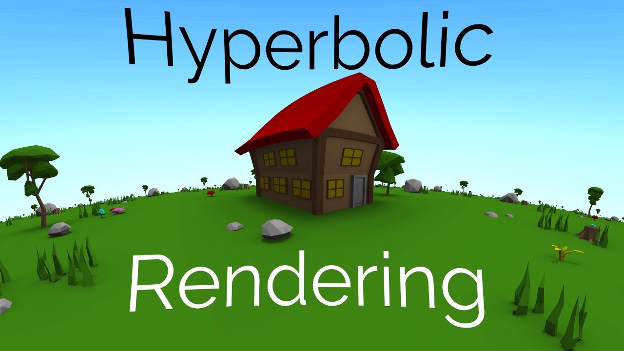
Hello, everyone. How is it possible to make non-euclidian game in unity? I mean how to convert 2D/3D game scene into hyperbolic space? I thought the best way would be to write an image shader and it would change the look how camera renders in game view. Please, can you give me any advice where to start? Or any learning materials? Thank you.
What is a "texture interpolator"?
Shader error in 'Custom/NewSurfaceShader': Too many texture interpolators would be used for ForwardBase pass (11 out of max 10) at line 136
And why does this have too many of them?
        #pragma surface surf SimpleLambert vertex:vert

        half _ShadowThreshold;
        half _ShadowIntensity;
        half4 _Color;
        sampler2D _NormalTex;
        half _Displacement;

        half4 LightingSimpleLambert(SurfaceOutput s, half3 lightDir, half atten)
        {
            half NdotL = dot(s.Normal, lightDir) * atten;
            half shadowAmount = round(NdotL + _ShadowThreshold);
            shadowAmount = clamp(shadowAmount, _ShadowIntensity, 1);
            half4 c;
            c.rgb = s.Albedo * _LightColor0.rgb * (NdotL * atten);
            c.a = s.Alpha;
            c.rgb = s.Albedo * shadowAmount * _LightColor0.rgb * _Color.rgb;
            c.a = s.Alpha;
            return c;
        }

        struct Input
        {
            float2 uv_MainTex;
            float4 pos          : POSITION;
            float4 grabPos      : TEXCOORD0;
            float4 grabPosDis   : TEXCOORD1;
        };

        sampler2D _MainTex;

        void vert(inout appdata_full v, out Input o)
        {
            o.pos = UnityObjectToClipPos(v.vertex);
            o.grabPos = ComputeGrabScreenPos(o.pos - _Displacement);
            //o.grabPosDis = ComputeGrabScreenPos(o.pos + _Displacement);

        }

        void surf(Input IN, inout SurfaceOutput o)
        {
            half4 bgcolor = tex2Dproj(_NormalTex, IN.grabPos);
            //half4 bgcolorD = tex2Dproj(_NormalTex, IN.grabPosDis);
            //half dist = distance(bgcolor.xyz, bgcolorD.xyz);
            //dist = saturate(dist);
            //dist = round(1 - dist);
            o.Albedo = bgcolor;
            //o.Albedo = tex2D(_MainTex, IN.uv_MainTex).rgb * bgcolor;
}```if my compute shader works on dx11 and dx12, is it expected that it should work on vulkan?
is it a bug if it doesnt?
i cant find any resources online about it and this issue is killing me
it's how many things youre passing from the vertex to the fragment shader iirc, you can get more if you go up a shader model using #pragma target 3.0 or 4.0
How do I change the sample texture 2d without having to delete it?

 I imported a shader I used from another project but the textures didn't carry over in the shader. So I just want to assign the sample texture 2d a different texture.
nvm, I got it.
uv seams shouldn't have anything to do with vertex positions. as malz pointed out, it can be a problem if you use uvs for the displacement but it you use local space position instead, there should be no problem in uv seams (well, the sources online probably referred to splitting the vertices which I believe happens on uv seams but it should have no affect if you use local space position to make the displacement)
Here's a devlog of someone doing it, and some additional links. It will include explanations/tutorials of hyperbolic space, which you probably already know, but it will get into the development details later.
https://www.youtube.com/watch?v=zQo_S3yNa2w
https://www.youtube.com/watch?v=pXWRYpdYc7Q

I present the easiest way to understand curved spaces, in both hyperbolic and spherical geometries. This is the first in a series about the development of Hyperbolica.
Chapters:
0:00 Intro
0:24 Spherical Geometry
2:33 Hyperbolic Introduction
3:53 Projections
5:37 Non-Euclidean Weirdness
8:31 Non-Euclidean Formulas
10:20 Outro
Hyperbolica
Trai...
This is the 3rd devlog for Hyperbolica where I talk about how I build and render hyperbolic worlds. If you haven't seen the first 2 videos in the series, make sure you watch them first or else this may be confusing.
Devlog #1: https://www.youtube.com/watch?v=zQo_S3yNa2w
Devlog #2: https://www.youtube.com/watch?v=yY9GAyJtuJ0
Hyperbolica on Ste...
heya, is it possible to use HDR color with an unlit shader? i'm returning an HDR color in frag but it doesn't get brighter when i turn up the intensity
lighting is irrelevant to color-space in the context of your question.
Getting HDR to actually work (HDR Output) on your system first, can be tricky. Can't tell anything from your question, but make sure you have HDR working on your computer and monitor first if you want "real" HDR. Otherwise, HDR is just an internal calc that gets mapped back to standard range.
Other possible meanings of your problem/question result in "Make sure your camera is set to render HDR color, and check graphics settings or render pipeline settings", depending on what you're actually talking about. And you'll need post processing. Read the entire page here, particularly that last section.
https://docs.unity3d.com/Manual/HDR.html
Also, see tut here: https://catlikecoding.com/unity/tutorials/custom-srp/hdr/
A Unity Custom SRP tutorial about supporting HDR, tone mapping, and more realistic bloom.
is there a way to create shader that doesnt rotate as the object its clipped to rotates?
For example. a texture on a ball (circle2D) that stays upright despite the ball rotating
ping to LMK 👋 thanks
all i'm really trying to do is get the brighter objects to have greater bloom. i can't enable HDR on my camera, though. i'm forced to use my graphics settings, which I can't change to use HDR
Huh? How are you supposed to use hdr colors if your camera isnt able to use hdr colors? That doesnt make much sense
Is there any way to include transparent objects in the depth texture?
well that's kinda it, i realized the issue is that my camera isn't using HDR colors. so that's what i'm trying to fix now
How may I ask?
that's what i don't know, dude. i rarely work in the standard render pipeline so i don't know how to modify the graphics settings to use HDR colors
Oh wait so you dont know how to enable hdr or you dont want to enable it for some odd reason?
So why cant you enable hdr on the camera?
because i am forced to use my graphics settings
which i cant change to use HDR
let me get screenshots hold on
here is the camera inspector window

here are the graphics settings

Just disable the Use Defaults option to access those
Well, then you're not going to get HDR!!!
What's the question?
Is your REAL QUESTION something like "How do I do bloom without HDR"?
@unique oarIf you can't do this ^^, you'll have to make all your other colors a lower value, and then use the highest value for bloomed things. Which will suck. Or you could try multiple layers and/or cameras, and draw the bloomed stuff with another camera and maybe between cameras add some special pass to tone-down the results to make sure it doesn't go into bloom range, but that's hacky.
tried moving a shader to a new version of unity, but now for some reason it is not transparent like in the gif, just becomes pure black instead
it was a move from 2020.3 to 2021.3


it also looks fine in the preview

but in the preview outside of shader graph it beomes ... this

only difference in the graph is that there is now a "sprite mask" node, but I can not find any documentation on it
sorry for such a wall of images and text, but I really have no idea what could be causing it
The blending is like this because of negative alpha values. Try using a Saturate node before putting it into the Alpha.
oh, gonna try that
also, I'm honoured to get a response from you, I love reading your posts about shaders Cyan!
now the preview in-editor seems fine, but when applied to an object on the canvas it still is a black hole
only when I set the base image textures alpha to 0 the texture that is hidden behind it becomes visible
scene itself + the preview look like this now

also, the end of the graph itself looks like this

does anybody know how can i cast shadow when 2d object is not facing the light?


this is my current shadergraph

if there is a setting for "two-sided", see if that one is checked

np, I totally forget about this one myself often lol
oh gosh, i didn't even see that. thank you!
chill? i thought it was an issue with my shader but i realized its something i have to change with the graphics settings
anyways, i tested it and it works now, thanks Aleksi!
I told ya to check camera and graphics settings....
@meager pelican i literally did, and that's when i wrote this message. you can see this is when i realized it was an issue with the settings
nm, communication is hard. That post read [to me] as if you were not ALLOWED to change the settings (you're forced to use them as default for some team project or something). Not that you didn't know how to change them.
Have you tried including these built-ins? https://docs.unity3d.com/Manual/SL-BuiltinIncludes.html
It appears unity_CameraProjection is automatically included via UnityShaderVariables.cginc
is there a way to set the required shader model target in compute shader?
i tried #pragma target 5.0, but it didn't seem to work and threw compile error
or is there a way to set the shader model of the entire project, i.e. globally?
for anyone wondering about the solution to my question earlier. use rotation matrix and pass the angle of the object ... im a dummy btw. 🥲
Better late than ever, but thank you very much kind person of the internet
I got a depth texture by adding "sampler2D _CameraDepthTexture" but the furthest the camera is, the closer the values are to zero. How could I get an evenly distributed depth texture regarding of how far the camera is from the object?
i have this outline shader from the Ultimate 10+ Shaders
how can i make the center transparent/invisable

is this shader made in shader graph, or in shader code?
with stock nope
would it be makable with shader graph cos id gladly swap if i can get the effect
I am having an issue with a custom shader crashing unity constantly. I get no error messages however. How do I debug what I did wrong in the shader?
it should be possible in either
There's macros/function nodes for that. Look for linear depth 0 - 1 functionality. IDK what pipeline/tool you're using.
why isnt the metrial working?

That can be a hard thing to do.
There are vendor supported/supplied debugging tools for GPUs. Getting them set up and working is a bit of a chore, but you can do it.
Generally, the easiest way is to comment out 1/2 the code (whatever makes sense) and see if it crashes. If it doesn't, then the problem is in whatever you commented out, or the inverse...if it still crashes it is in the non-commented part. Repeat, doing a binary search type of process of elimination.
Generally, it will be either invalid memory access (think array out of bounds) or infinite loops, NANs, etc.
Remember you can check variables by outputting colors, maybe after remapping. Just throw in a bunch of "return <expression>" stuff at various points.
There's always RenderDoc and PIX too. See unity docs on shader debugging.
Looks purple to me.
What's not working?
you are using a lit material, that's why the colour became darker in the shadow
You should check runtime support levels in C# side.
https://docs.unity3d.com/ScriptReference/SystemInfo-supportsComputeShaders.html
https://docs.unity3d.com/ScriptReference/ComputeShader.IsSupported.html
There's also a pragma require https://docs.unity3d.com/Manual/SL-ShaderCompileTargets.html that you might want to try.
its suppose to be light purple
in the pic u can also see that the metrial is light purple
yet its dark purple
this is how it should look

I don't see the "lighter hat-band" on the screen shot you gave (the mesh I mean, regardless of color).
But, if it were me, I'd use a texture with two or more colors in it, and then in the modeling program map the UVs of each part of the model to the proper colors in the texture. Basically a modeling issue, not a shader issue per se. Unless you want to do something funky with a shader effect or lookup.
also, you might need to add an ambient light
Thnak you! I made it in shader graph and am now trying to unplug individual things to see what causes it.
Why cant i select the material?

As a guess, since you're using the sprite default material, you should make a new sprite material first, assign it, and then see what happens.
Yeah, same idea...unplugging = commenting, and outputting something (maybe through a remap node) to the albedo output to debug values. Good luck! 🙂
I created a material and this hapenned ;-;
IDK, but not really a shader question...
Maybe you'll get more help/experience in a different area, like art assets or whatever?
i think im gonna give up on the lights since its my first game, ill learn it other time
can i ask a material related question here? or in the art assets just like you said?
Unless you're making a custom shader, you'd probably get more help in the art assets. But it depends on the question! If you want to know how shaders use materials, maybe here????
Idk ;-; my... material doesnt really looks white

That's lighting. You should find a tutorial on materials, IMO.
Ok thank you
bruh. why is transparency soo hard
i just want the black outline, the red sphere should be invisible

ye its not a shader problem, but why is the cube looking like this?

In blender its all fine

then mabye your shader is inverting the normals
how do i stop it?
is it just the standard unity shader?
ye
ok then the model has inverted normals
Built-in. I came across them but I just thought "linear" meant from 0 - 1 xD
I'll definetly give them a try now, thanks
in blender in edit mode with the mesh selected

now it works thanks
ur welcome
Don't draw it....(that's the best solution, fastest pixels are the ones you don't draw). But I'd need more info to tell.
Is it a multi-pass shader? What outline method are you using?
Are you in the opaque queue and trying to output a transparency? You'd need to be in the transparent queue for that.
Also see "Color Mask" option in shader docs, that might help you, if you're drawing a stencil but don't want to output color info.
i can disable it in the shader then the entire thing goes black, as i understand the main part is rendering over the outline

without the center its all outline, so i want to render null over the outline effectively canceling it out
OK, firstly, what are you trying to do? A force field? Just a big circle as an outline? Do you need the center to fade in and out?
Secondly, are you working in a transparent queue?
IDK if you're allowed to post the shader code of an asset from the store.....but you need to read it and figure out what it's doing in what queue.
its a tower defence game, the outline shows everything in the turrets range

what queue is it using?
Transparent
its creative commons 3.0 so i can share and adapt
Shader "Airscrach/Range"
{
    Properties
    {
        _OutlineColor ("Outline Color", Color) = (1,1,1,1)
        _OutlineWidth ("Outline Width", Range(0, 4)) = 0.25

        [Enum(UnityEngine.Rendering.CullMode)] _Cull ("Cull", Float) = 2
    }
    SubShader
    {
        Tags { "RenderType"="Geometry" "Queue"="Transparent" }
        LOD 200
        Cull [_Cull]

        Pass{
            ZWrite Off
            CGPROGRAM
            #pragma vertex vert
            #pragma fragment frag
            struct appdata {
                float4 vertex : POSITION;
                float4 tangent : TANGENT;
                float3 normal : NORMAL;
                float4 texcoord : TEXCOORD0;
                fixed4 color : COLOR;
            };
            struct v2f{
                float4 pos : SV_POSITION;
                float3 normal : NORMAL;
            };
            fixed4 _OutlineColor;
            half _OutlineWidth;

            v2f vert(appdata input){
                input.vertex += float4(input.normal * _OutlineWidth, 1);
                v2f output;
                output.pos = UnityObjectToClipPos(input.vertex);
                output.normal = mul(unity_ObjectToWorld, input.normal);
                return output;
            }
            fixed4 frag(v2f input) : SV_Target
            { return _OutlineColor; }
            ENDCG
        }

        ZWrite Off
        CGPROGRAM
        // Physically based Standard lighting model, and enable shadows on all light types
        #pragma surface surf Standard fullforwardshadows

        struct Input
        { float2 uv_MainTex; };
        sampler2D _MainTex;

        void surf (Input IN, inout SurfaceOutputStandard o)
        {
            o.Albedo = float3(1,1,1);
            o.Alpha = 0;
        }
        ENDCG
    }
    FallBack "Diffuse"
}
the first CGPROGRAM does the outline, the second one is the red part
Add a line at the end
after the o.Albedo line
That says
o.alpha = pixel.a;
Alpha may need to be capitalized.
o doesnt have an alpha value
Just a sec...
{
    fixed3 Albedo;      // base (diffuse or specular) color
    fixed3 Normal;      // tangent space normal, if written
    half3 Emission;
    half Metallic;      // 0=non-metal, 1=metal
    half Smoothness;    // 0=rough, 1=smooth
    half Occlusion;     // occlusion (default 1)
    fixed Alpha;        // alpha for transparencies
};```
capitalize the alpha.That's from here, BTW: https://docs.unity3d.com/Manual/SL-SurfaceShaders.html
Grrrrrr.
OK change it to
o.Alpha = 0.25;
no change
Still solid?
yup

Prove to me that that pass is the one drawing it.
Change
o.Albedo = float3(0,1,0);
just temporarily. Comment out the original line
yup, its green now
f---
It's not honoring the transparency, so maybe we're not in the right queue for some reason.
Let me dig around a bit.
You can put those two lines back to normal.
Thanks for trying it.
they dont really matter as when it works they wont be visable
We can try to not do that pass at all.
u get this
im thinking it shouldnt be a surface shader cos it really only needs to be unlit cos its transparent
That's true, and a good point. But I'm trying to work in your context. Although it would be faster to not bother with lighting calcs.
The thing is, you're right, it's drawing "black" over the whole image. My bad. Black is the outline color in your case.
Then it passes again and draws the real color.
It does not update the depth buffer on the outline pass.
It is extruding the object along the surface normals by an amount specified by the outline width. For the outline pass.
That method won't give you what you're looking for.
The hacky way to fix it is to do a grab pass and on the 2nd pass of this shader re-draw the background over top of the black. But that sucks.
Another hack would be to do additive blending. Black adding a "nothing". But you can't really do a black outline that way...could add in some other color.
But it would highlight the whole area. Like adding in a color of .1,.1,.1 to brighten it all up.
i was basically doing that with my old range shader
There are other ways to accomplish this same thing, using different methods of course.
What shaders do you use to draw everything else?
Normal stock ones?
95% yes
Wait.
What is outline color set to on the material?
Try changing the alpha of that.
It will darken the result due to blending, but you should get a darkened TRANSPARENT area.
the outline doesnt use transparency so it does nothing
could i maybe chang the culling mode for each pass?

The code you posted shows it in the transparent queue and outputting a float4.
yea
So this assumption is wrong. I think.
Where did that last pic come from?
i set the cull to front
I see. But that will block out the stuff behind.
yea
i got it working unlit
Shader "Airscrach/Range"
{
    Properties
    {
        _TransparentColor("Transparent Color", Color) = (1, 1, 1, 0)
        _OutlineColor ("Outline Color", Color) = (1,1,1,1)
        _OutlineWidth ("Outline Width", Range(0, 4)) = 0.25

        [Enum(UnityEngine.Rendering.CullMode)] _Cull ("Cull", Float) = 2
    }
    SubShader
    {
        Tags { "RenderType"="Geometry" "Queue"="Transparent" }
        LOD 200
        Cull [_Cull]

        Pass{
            ZWrite Off
            CGPROGRAM
            #pragma vertex vert
            #pragma fragment frag
            struct appdata {
                float4 vertex : POSITION;
                float4 tangent : TANGENT;
                float3 normal : NORMAL;
                float4 texcoord : TEXCOORD0;
                fixed4 color : COLOR;
            };
            struct v2f{
                float4 pos : SV_POSITION;
                float3 normal : NORMAL;
            };
            fixed4 _OutlineColor;
            half _OutlineWidth;

            v2f vert(appdata input){
                input.vertex += float4(input.normal * _OutlineWidth, 1);
                v2f output;
                output.pos = UnityObjectToClipPos(input.vertex);
                output.normal = mul(unity_ObjectToWorld, input.normal);
                return output;
            }
            fixed4 frag(v2f input) : SV_Target
            { return _OutlineColor; }
            ENDCG
        }
        Pass{
            ZWrite Off
            CGPROGRAM
            #pragma vertex vert2
            #pragma fragment frag2
            struct appdata2 {
                float4 vertex : POSITION;
                float4 tangent : TANGENT;
                float3 normal : NORMAL;
                float4 texcoord : TEXCOORD0;
                fixed4 color : COLOR;
            };
            struct v2f{
                float4 pos : SV_POSITION;
                float3 normal : NORMAL;
            };
            //render as transparent
            fixed4 _TransparentColor;
            v2f vert2(appdata2 input){
                v2f output;
                output.pos = UnityObjectToClipPos(input.vertex);
                output.normal = mul(unity_ObjectToWorld, input.normal);
                return output;
            }
            fixed4 frag2(v2f input) : SV_Target
            { return _TransparentColor; }
            ENDCG
        }

    }
    FallBack "Diffuse"
}
What's ticking me off is that the same thing should work with a lit shader and give you 3d lighting easily, so you'd get a "rounded" lighting effect.
Did you try to change the outline color's alpha? It was still 100% opaque?
yup i cant get alpha to effect anything
But you can with vert/frag now? What's it look like now? Just out of curiosity.
bassically the same but unlit

nm, I thought you said you got it to work.
frack. Must be something I'm forgetting about surface shaders.
if it were me, I'd look for a "force field" shader that does both sides (front and back) in transparent. But that's not an outline, unless you find one that has that.
thats what i originally looked for
@rotund tundra
Anyway, there's other ways.
One way is to draw a stencil with the original (not extruded) object. No output to the color buffer, just setting the stencil.
Then draw the outline extruded, honoring the stencil and not drawing where the stencil is set.
But you won't get a "full circle" on the bottom/terrain, you'll only get the front half.
Unless drawing both sides works (haven't tried that).
Also on your original surface shader, try changing the tags to
Tags {"Queue" = "Transparent" "RenderType"="Transparent" } , not "geometry" which is what I think might be f-ing it all up.
@rotund tundra
nope unfortunately
And also try:
#pragma surface surf Standard fullforwardshadows alpha:fade
that's in the 2nd pass
i got this but as you said its additive so it doesnt quite work


Yeah. That's the next thing to look at...what you want to do with blending.
But, your outline will also be transparent, unless we bag all this and do the stencil thing.
that blending equation you posted is "standard transparency". So you should now be able to set colors as you wish. But the problem is that the full-object extruded outline pass will draw the transparent outline color on the whole thing, unless you use a stencil.
what exactly is a stencil?
ah
Basically, it's a stencil buffer, similar to a depth buffer concept.
It's there for each pixel, and there's 8 bits you can screw with.
The gpu has stencil test/set hardware.
So you draw something and set the stencil. You don't even have to write colors or depth.
Then you can draw something else (or the same thing again) and check the stencil values. The gpu is configured to do this IN HARDWARE
Such that it won't even call the pixel shader if it can skip the thing.
So there's setting and testing.
so could we stencil the inside then ignore the stencil when drawing the outline?
YES! That's what I was saying above. 🙂
ok cool
But you honor the stencil...you draw where there is no stencil from the original object (the "inside"). I know what you mean, you "ignore where it is stenciled".
So start by reading here:
https://docs.unity3d.com/Manual/SL-Stencil.html
Oh, ok.
Yes, it looks weird. It's not that bad.
It is this way because you're actually configuring stenciling "hardware" so it can be smart about all this stuff and quickly skip pixels that don't pass.
that makes sense
Similar to how it can skip pixels that don't pass an early z-buffer test for depth.
But it's not a z-buffer, it's a stencil buffer.
😉
Pass{

            CGPROGRAM
            #pragma vertex vert2
            #pragma fragment frag2
            #include "UnityCG.cginc"
            struct appdata2 {
                float4 vertex : POSITION; float4 tangent : TANGENT; float3 normal : NORMAL; float4 texcoord : TEXCOORD0; fixed4 color : COLOR;
            };
            struct v2f2{
                float4 pos : SV_POSITION; float3 normal : NORMAL;
            };
            //render as transparent
            fixed4 _TransparentColor;
            v2f2 vert2(appdata2 input){
                v2f2 output;
                output.pos = UnityObjectToClipPos(input.vertex);
                output.normal = mul(unity_ObjectToWorld, input.normal);
                return output;
            }
            fixed4 frag2(v2f2 input) : SV_Target
            { return _TransparentColor; }
            Stencil{
                //stencil the inside of the outline
                StencilEnable
                StencilReferenceValue 1
                StencilPass 0x1
                StencilFail 0x0
                StencilZFail 0x0
                StencilWriteMask 0x1
            }
this look kinda right?
i let copilot take the rains cos im a bit outta my depth here
hmm
im looking at the docs and this doesnt seem right
oh
it doesnt recognise stencil
I'm going to let you google around rather than fill this chat up.
Stencil would go above, outside of the frag. in the pass part.
See the docs. Like draw the sphere using:
             {
                 Ref 2
                 writeMask 2
                 Comp Always
                 Pass Replace
             }            ```
Maybe with COLORMASK 0 before the stencil command.
https://docs.unity3d.com/Manual/SL-ColorMask.html
you could move your lower-pass to the top (first) pass and do a stencil.
Then in your outline pass you'd do something like:
```            Stencil
             {
                 Ref 2
                 readMask 2
                 Comp Less
} ```But I haven't tried that. I'd have to pull up Unity and screw with it. I'll leave that to your google-fu.
Hey guys! I'm following a tutorial to create a toon shader (https://www.youtube.com/watch?v=RC91uxRTId8&ab_channel=NedMakesGames) and at 11:05 he tells to add the keywords to the material. I'm using the latest version of unity instead of 2020 and it looks different but also works different. I can't seem to find out how to add the keywords to the material.
In the video there's a field to add the keywords. Version 2021 has a size option at Valid Keywords. When saying the size has to be 3, it defaults back to 0 and adds 3 to Invalid Keywords. How do I add the 3 keywords to the material?

sorry for ping but i just wanted you to know that i got it working,
thank you soo much for your help!

Nice!
BTW, if you do a lit surface shader, at the end/last pass or do lighting calcs in a vert/frag to self-shadow, you can use the now-working transparency to "tint" the inside as much as you wish. Lit would be shaded of course, and unlit would be a solid color of course.
But it doesn't look like you really want that. But you COULD do it. 😉 🙂
with cull off it might be a cool 2-sided effect.
why does my shader give this error every time it compiles? it doesn't break anything but it's just really annoying to stare at an error while working on other things

Pick another name for color property, this one already exists
doesnt change a thing
theres not even a single property with the reference or name _Color in the entire shader
i even looked through the compiled code
You can see hidden properties if you set inspector in debug mode
ok i managed to find the little bugger, thanks for the help
Hi, my shader is "switching" between two completely different looking versions

What I would expect
And then there's this one

Im using urp and these are the tags```cs
Tags {"Queue"="Transparent" "RenderType"="Transparent"}
Blend SrcAlpha OneMinusSrcAlpha
LOD 100
If you need anything else dont hesitate to ask
Thanks!
I did some more testing
this only happens sometimes when its infront of a non working skybox
Hello,
when upgrading to a newer version of unity this shader stopped working with transparency in-game, even though it's fine in preview, any idea what could be the cause of this?


I know I posted about this yesterday, but it just doesn't work in-game in the end
Does it work when applied to a quad mesh or sprite maybe? (Don't really like using Shader Graph with UI as it's not really supported properly. Would be good to confirm if that's the problem or not)
will try it now
it's just weird that it did work perfectly fine in the previous version
it seems fine on a quad
huh
Upgrading unity is always asking for disaster
then what could be causing it to not be fine on a raw image?
At a guess it could be that the graph generates more passes (e.g. ShadowCaster/DepthOnly, though not sure if that is generated with the Sprite Unlit graph type, I don't do 2D stuff often). It's possible the UI is trying to draw all passes ontop of eachother, rather than just the main forward one.
I guess one of the updates messed that up, dang
and there is no way to fix it other than going to either an earlier version or hoping some future one fixed it?
If it is to do with extra passes, you could generate code from the graph and remove them.
Or just avoid using graph shaders on UI. Replace it with a quad?
ah, hoped this version would have less hacky solutions to stuff as I saw in release notes a lot of 2d features leaving the experimental phase
will try both of solutions ya said and see which one works best
this seems to be in the generated code

- the tags

nothing seems to be out of the ordinary, unless I'm overlooking something
oh, checking on the issue tracker it seems that this is "by design"??? https://issuetracker.unity3d.com/issues/shader-graph-shaders-from-shader-graph-dont-work-on-ui-with-canvas-render-mode-set-to-overlay
Reproduction steps: 1. Open "1193291" project 2. Notice that the Image has Perlin Noise 3. Select the "Canvas" Game Object -> "Ca...
after finding this thread the thing that fixed it was ... changing the camera mode from overlay to screen space - camera https://forum.unity.com/threads/shader-graph-ui-image-shader-does-not-work.1202461/#post-7683259

Unity Forum
Unity 2021.2.3f1
Shader Graph 12.1.1
This is a simple Shader Graph shader.
Screenshot1. Universal - Material - Sprite Unlit: Alpha is wrong.
[ATTACH]...
also, thank you so much for being patient with me!
Hey there! How do I create a simple outline shader in shadergraph? I followed a lot of tutorials but none of them gives me the same result. Right now i'm stuck with this one, what can I be doing wrong?


Are depth textures used only in post processing shaders?
You mean depth buffer or depth texture? Depth texture can be used for lot of different things on regular surface shaders too (like water refraction etc.)
Is there a way I can not only pick a random point on a UV/surface, but have it be weighted? I get I could use the channels of colorful noise to get an x and y coordinate, but not how to weight it
In what way to you want to weigh it?
Have a higher chance of placing the point in a certain area
Ideally I would be able to input a texture, with black being no chance of the area getting picked and white meaning 100%
That's a bit less obvious to do in a single pass but if your weighting can be captured as some function of uv space it's pretty straightforward (e.g. weightedUv = weigh(uv) where weigh can for example take into account the distance between your sample and the center of your noise texture).
What you want (a 2d texture with 0-1 indicating odds of that position being picked in your noise texture) is both hard and slow.
Hmm. What about voronoi pattern. That’s a function, right?
Yes, although depending on how you want to use it also computationally expensive. Perhaps if you give some context as to your true need people can weigh in on possible alternatives to it being texture based (for example, there are ways to create random values that don't involve input textures in shaders, or precalc a LUT texture and use that)
For example, you could pregen a 2d texture that on the U axis is random noise and on the V axis is your weighing from 0 to 1 such that the texel value is U x V. That way you can sample a random U with your input weight V and get a weighted value.
Actually. Maybe a different approach is necessary. Perhaps I could have some sort of math operation that could push the coordinates towards being a certain value. Like taking the color noise texture, and then overlaying my probability field over it in a way that would take the RG channels and modify them
Ah so the probability field is an input you already have and need?
Yeah that’s the texture
My goal is to spread little textures on the surface of something in a random way, but be able to weight it to appear more often in certain areas
Hm, but isn't that as simple as multiplying your probability field with the noise texture? That should translate smoothly to fragments with higher probability being more likely to reach a certain treshold value.
But wouldn’t that push the coordinates more towards the corner
Or 0,0 / 1,1 rather
how do I make an outline in shadergraph? I've followed some tutorials but none seems to be working
How so? If for each fragment your "need little texture here value" is a random noise sample times your 0-1 value of the probability texture you provide than it'll just be a new texture with 0-1 values skewed towards your probability field values. Then you determine some threshold value for where you want your little textures.
Hmm. I’ll be home soon, I’ll have to try it. I feel like it can’t be that simple, haha
Wait, what do you mean threshold?
If I understand your need correctly I think it is. The only additional choice is static noise texture versus dynamic one (the former would result in the same probability field resulting in exactly the same spots where you want your other texture, a dynamic one would make that noisy).
Well if your inputs are P (probability field value, 0-1) and N (noise value, 0-1) for each fragment/texel than multiplying them gives you a 0-1 value. You probably want to go from that to a on/off type value. E.g. if your calculation results on values below, say, 0.5 then no little texture, and above that you start blending it in.
I only really create shaders in code so whatever the equivalent of some clamp or smoothstep function is in shadergraph.
Whats the C# equvilant of
float3 A = mul(Matrix4x4, float4(B, 0));
Just Vector3 A = Matrix4x4.MultiplyVector(B); or the Unity.Mathematics equivalent I think or am I misunderstanding your question?
oh really?
wait is that different than matrix4x4 * B?
It is different but I think you actually want a straight matrix multiplication (which is Matrix4x4 * Vector4)
MultiplyVector does some extra lifting.
ok
but theres no efficient way to convert from Vector3 to Vector4 without breaking into components manually
No I mean the Vector3 to Vector4
Yes, that's implicitly converted
oh wait really? hang on
Vector4 a = new Vector4();
Vector3 b = m * a;
``` compiles just finew component is discarded obviously but I assume that's what you're looking to do here.
I need the w component to stay and be 0
well a vec3 doesn't have a w component and your A input is I assume one where you can set the w = 0 so it's 0 or undefined all the way through.
so, equiv to float4(float3, 0)
so Matrix4x4 * Vec3 is equvilant to mul(Matrix4x4, float4(float3, 0))?
Yes, Vec3 is implicitly converted to Vec4 with w = 0 iirc. But this is one of those "try to be sure things". I can't remember the last time I needed that.
hello there can anyone help me figure out what's wrong with my outline shader?

ok thanks
You tell whats wrong we try to find solution to it. Id set the alpha clip threshold to 0.5 but other than that i see nothing wrong. So whats wrong? What it looks if its not correct?
@dim yoke it looks like this
not exactly what I pretended
I've followed a lot of tutorials but none gives me the same result
Either it fills everything with the color or something like this, and it never looks like an outline as I wanted
so, i want to do something super simple using HLSL but dont have the first clue how to do it
i essentially just want a circle thats on the surface of the object, that i can also change the "blur" or smoothness of
with configurable radius size and smoothness
im forced to use 5.6.3
Moving along normals wont work for flat shaded meshes. Have you tried any existing outline effects from asset store for example?
I've tried simply multiplying the positon, why doesn't that work either?
I'm trying not to use the outline from the asset store, it should be simple enough for me to be able to replicate :/
Well its not perfect but should work better atleast
i'll show you the result just 1 sec


it now gives me this it's really weird
how can I just have the red outline but show the real texture in the middle?
Did you try to set the alpha clip threshold to 0.5?
Front face culling should do that but if it doesnt happen, idk why
idk it's really weird

i changed the threshold to 0.5 but arranging the options the resulkty is never good


i mean shouldn't the outline depend on the camera?
how would i make a simple circle on the surface of an object with shaderforge?
configrable vignette radius and smoothness
hey uh guy so im tyring to create a retro effect for my game but the camera says display 1 no camera
[7:20 PM]
how do i fix that
[7:20 PM]
and make it work
i meant it says
camera display 1 no camera rendiring
Does anyone know how to fix this weird rendering with a transparent fresnel shader?

I have it rendering on both sides since the player is meant to be able to see the effect while inside the sphere.
Another issue is that the effect becomes a lot brighter when inside the sphere.
so, UVs start in the bottom left corner right
at 0,0
which means if i want to scale something its like
scales from there
but how would i make it scale from 0.5,0.5? if that makes any sense
(the center of the UV)
ive tried shifting it over to 0,0 , then scaling it, then moving it back but that doesnt seem to change anything?

Do it on paper first.
But note that UV's wrap around assuming wrapping is configured for the texture sample. That's how tiling and offset work. Tiling is multiplying, and offset is adding.
But I'm not sure exactly what you're asking. Do you want your logical-zero-zero sample to be the center of the texture? If so, you'd add (.5, .5) to your UV value. But your lower left corner would be (-.5, -.5) and your upper right corner would be (+0.5, +0.5). That's offset, not scale.
To scale, you'd do some multiply operation. For example to scale a texture to be 2 x 2 on a quad, you'd multiply the UV (which is the 0,0 at lower-left one) by 2.0 in both x and y.
And I have no idea what your pic is showing.
essentially what im trying to do
is like
a vignette for a scope right
its just a circle thats on the surface of a circle object
and based on the camera distance, it grows/shrinks
scope shaders are a bit more complicated than just tiling and offset. I suggest you google around for "scope shader" and see what you get. There's several methods depending on what you want exactly, but the involve a different perspective.
hey there, sorry to botehr you once again but I followed this tutorial 100% and i'm not getting the same result... am I missing something? Any unity update? https://www.youtube.com/watch?v=XPGpaA-JExA

Tutorial to how to make a very basic outline effect using shader graph.
OK, then do a distance calc from (0.5, 0.5) and use the result as a "degree of darkness" scaled by whatever math you want.
i managed to fuck around with the UVs and get the scaling working
i guess
like the center point of the circle is at 0,0
so it should work
im too tired for this my brain is explODING
i just want the camera distance
but i cant find that
I have no idea how to fix this rendering issue. (Picture below)

I haven't messed with shader forge in a long time.
And by "camera distance" you mean what, exactly?
Pixel depth is probably a node. Maybe linear eye depth 0 to 1 type of thing.
Distance from camera to scope would be the camera pos in world space, and the scope position in world space, run through a distance calc.
hlsl has a built-in distance function. And IIRC also a squared distance function that avoids doing square roots (faster).
There's probably a node for distance calc between two points.
In code it looks like:
float dist = distance(point1, point2);
There ya go!
Without more info on the shader, there's no way anyone can really answer that. I suspect lighting issues.
alright, so essentially the last thing is adding blur
i dont know how i would even start that
ill do that tomororw
It's a transparent material with a Fresnel effect on it.
has someone here made a bloom shader to attach to objects? can i have it pls?
That's called Post Processing
lit or unlit?
Is it doing environmental reflections?
no post processing blooms everything
Reflections and Lit.
Well, that's likely part of the problem...
I want the shader script to give to my material
is there a library of unity shaders somewhere?
it appears id have to make my own
Not exactly. It blooms whatever is set to bloom (qualifies for blooming).
The thing is...you cannot easily draw outside of a mesh bounds on a shader for the object. That's why bloom is done in post-processing.
So i have to download the Post Processing package?
ok thanks. wonderful. saves me a bunch of effort
yes im super happy now that you told me about this. 😃 thanks
First shader 😬

I have a question, im using a singular dot texture to create this effect here and im tiling it. But it would look a lot cleaner if i could have it tile hexagonal instead of qubic. Is there any easy way if achieving that kind of effect?


This is how i want it to look
Thanks for the help, I changed my material to Unlit and immediately the rendering looked a lot better.
Could you just make seamless texture like this and use it instead?
i thought of that, but im pretty sure that will cause some of the dots to look choppy, but i suppose i can try
If you make the resolution high enough, you should have no problem with that
yeah that seems to have worked

thanks, also i dont know why but for some reason i cant figure out how to apply the texture in screen space
anything ive tried the texture ends up being warped
looking along world x and world z.


this is not exatly what i currently do ?
Show the shader code/graph
            fixed4 frag (v2f i) : SV_Target
            {
                float3 N = normalize(i.worldNormal);
                float3 V = normalize(_WorldSpaceCameraPos - i.wPos );
                float3 H = normalize(_WorldSpaceLightPos0.xyz + V);
                // Diffuse
                float shadow = SHADOW_ATTENUATION(i);
                float NdotL = max(0.0, dot(N, normalize(_WorldSpaceLightPos0.xyz)));

                // Cartoon Detail
                float4 _DetailTex = tex2D(_PatternTex, _PatternTex_ST.xy * V);
                float dots = step(_Size * NdotL, _DetailTex);
                float4 light = floor((NdotL * shadow)/_Detail * 1-dots) * _LightColor0;

                float4 DiffuseToon = (light + _AmbientColor) *_LightIntensity + _Brightness;

                // ... the rest of the shader
            }
this should be plenty to se the problem
Hello guys I need help to make a sphere that while following the player throws particles that when touching the ground draw a mesh or a texture.
I want to use a CustomPassFullscreen for it, but I don't know how to do the shader part
First I'm trying to render the pixel redder the closer to the camera it is, but I can get it to work.
float4 FullScreenPass(Varyings varyings) : SV_Target    {
float depth = LoadCameraDepth(varyings.positionCS.xy);
float customDepth = LoadCustomDepth(varyings.positionCS.xy);
return float4(1.0, 0, 0, depth-customDepth);
}
I meant depth textures. Basically, I was trying to compute fog in a local volume, like a cube
And I thought about using the depth texture, color the white part and sample the main tex so the black part is invisible
I'm still a biginner about shaders though
anyone got any idea why i can't see shadows in game view?

Maybe "Render Shadows" is deactivated on your camera?
good ^^
how do i remap an alpha like this but with 2 colors? cus gradient cant be make exposed and i want to edit it from outside

rename the file in a text editor
You could just sample an image instead.
anyone know if it's possible to blur during mipmap generation instead of the usual sharpening filters?
Use a Lerp node with a and b been your wanted colors (with can be exposed) and the alpha is the input form the texture
if you still need more curve / gradient controll make a Black and white gradient and use it in between the texture and the lerp alpha
Anyone think they could help me figure out how to get a cubemap reflection to work in shadergraph ?
I can tell that the cubemap is doing 'something' but it seems to be treated as if it were a single color
as if it's tiling were 0.00001 * 0.00001
My current implementation

What's "World Space" coming in as?
I have no idea 👀
higher res version of screenshot: https://i.imgur.com/DaMpza1.jpg
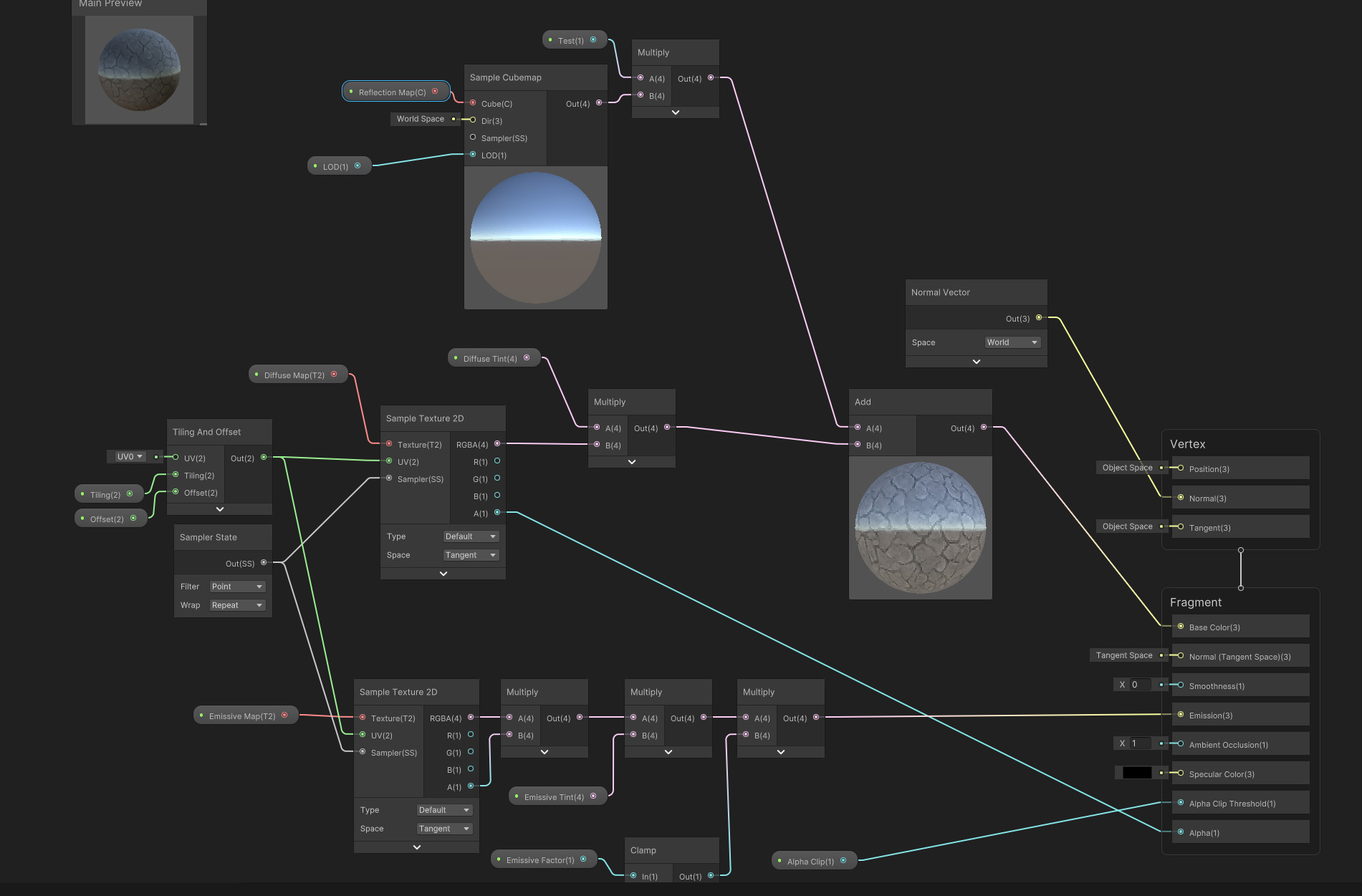
You want that to be the surface normal direction, in world-space.
https://docs.unity3d.com/Packages/com.unity.shadergraph@12.1/manual/Sample-Cubemap-Node.html
It might default to the world-space surface normal if you just delete the link to "World Space" variable. Not sure though.
You've already got a world space surface normal in the graph though, so you could try plugging that in to "Dir" for the sample cubemap. (You'd have two lines off it, one to the cube sample, the other to the normal input on the vertex stage). @fervent flare
hm it won't let me plug the world space surface normal into the normal slot of the vertex section
is that maybe because one is object space and the other world space ?
how can i overlay a texture on an object in screen space? in hlsl? whatever i try the texture doesnt keep the view angle for the camera so its in world space and not screen space
you have to use screen coordinates as a uvs on the texture sampling
What resources would you guys recommend to get started with shaders as an artist? from general concepts and fundamentals to intermediate expert level (and engine-agnostic) preferably.
I've found a few nice, such as Ben Cloward, Freya Holmer, TharleFX and a few others. I'd like to know if there are good sources of info on these eslewhere that explain things from an artist's POV, TIA
Do u get the screen coordinates from computeScreenPos(v.vertex)?
Or is it something else?
Your pic showed it as world space.
They should both be world space, if your original is correct. Otherwise, just use two normal nodes, one for world and the other for object.
But, the one going into the cubemap direction is world-space per the docs.
Pretty sure, but I'm kinda guessing going off the docs.
https://thebookofshaders.com/ is a good place to start, and fiddling in tools like www.shadertoy.com will help as well. I'd avoid using ShaderGraph or any similar shader composition tools personally as they tend to obfuscate important performance and correctness issues but that's obviously highly subjective.

The Book of Shaders
Gentle step-by-step guide through the abstract and complex universe of Fragment Shaders.
anyone knows how i get the screen cords in shaderlab? ive tried thiis ^ and _ScreenParams.xy
I believe so. you do that in vertex or fragment shader?
that should be vertex
in what space is v.vertex?
you have to make it a clip pos
o, that would make sense
thank you! this seems like a wonderful resource. Regarding the shader graph thing, could you elaborate on 'performance and correctness issues'? What information is being obfuscated there?
hey i'm really new to unity (i'm literally only using this to import a model into VRC) does anyone know how to fix a problem regarding textures not going on certain parts of a model? i was told by a friend to "mess around with shaders" but i don't really know what that means. all the textures show up except for certain parts of the jacket. if you need pics i can send em
thankyu, that seems to be working, now i just need to tile it correctly
yeah, please share some screenshots of the asset and textures


Can you share a screenshot with the wireframe enabled? and where are you seeing issues exactly? The front jacket part?
yes, the front jacket is not showing up in the regular mode, it is showing up in render paths though


@hoary merlin

it looks like the right jacket mesh is missing when imported to Unity
how exactly do i fix that?
The normals for those faces is probably inverted. Unity does back-face culling by default.
is that a unity thing or a blender thing i have to do?
i assumed the same thing, but the wireframe doesnt seem to show the jacket either
if it's a normals issue, you'll need to invert the affected mesh's face normals in Blender
i'm assuming that's a blender thing?
but my main confusion is that it shows up on render paths
so it knows the texture is supposed to go there
You can view the face orientation in blender if you use this. Front faces are blue, back faces are red.
Can recalculate normals on faces using Shift+N (or Ctrl+Shift+N for inverted)

yeah, I looked it up.. The one going into the vertex stage on the master stack is object space. Just use two of them, one for the master stack in object space, and the other for the cubemap direction in world space.

i cant figure out why the texture is streching on the edges. this is how i get the screen space and apply it as the uv
o.pos = UnityObjectToClipPos(v.vertex);
o.scrPos = ComputeScreenPos(o.pos);
float4 _tex = tex2D(_PatternTex, _PatternTex_ST.xy * i.scrPos);

When in the fragment, you need to do i.scrPos.xy / i.scrPos.w to handle the perspective divide and obtain the true 0-1 screen position.
oh, true. i actually have read that but i keep forgetting, thanks
so unity says that by using dx12 and #pragma use_dxc, I can get access to shader model 6 stuff, so why do shader model 6 functions not work and are unknown
Also, how do I exclude compiling shaders for dx11, but DO compile them for dx12?
What is the best way to modify the values of a material shader in shadergraph per instance that it is applied to?
There's nothing special about shader graphs, they're regular shaders.
You use Material.SetXXX methods as usual.
and you use Renderer.material to access the material - that will create a unique instance of the material for that particular Renderer
I'm trying to make a Halftone shader by following this excellent guide: https://weber.itn.liu.se/~stegu/webglshadertutorial/shadertutorial.html. I ported this to Unity and expanded on this shader to support dot frequency on the x & y axis separately for non 1:1 aspect ratios. This works well for 0 degree rotated pattern (Y part of CMYK), but for other angles like 45 degree the dots deform. How could I fix this shader to produce perfectly round dots at any rotation angle? Here is my shadertoy summarizing the problem: https://www.shadertoy.com/view/7sccW8

does anyone know how to make a sphere render from inside out?
I could really use some help with that
Invert the normals ?
got any reference?
The easiest would be to just create a sphere mesh in a 3D tool with inverted normals 🙂
Any URP graph ideas tho? This sounds crude.
iirc, urp doesn't have a front face culling option, so the only way to do it is to enable double side and the shader, and discard pixels of the front face.
This is sub-optimal and having a mesh with already inverted normals would really be better.
When it come to CG crude is always better 🤣 🤣
is it possible to create custom layered material in unity using shader graph ? seeking on internet and lots of people asking same question but still left unaswered.
Why.
What you're asking is as easy as :
- open blender
- create new sphere
- flip normal
- export
Layered by "layering multiple textures set like a terrain" : yes
Layered by "layering passes" : no
how do i flip normals?
In edit mode, select all faces, alt+n for normals menu, select "flip"
yes, im looking layering multiple textures set like a terrain, but i'vent seen for shader graph tutorial/resources out there, do you know any for guide ? i expect some basic guide to create one, and put my needs after proper setup done. i wish it only needs shader graph and no custom node needed.
what faces? I've sincerely never used it
No custom nodes is needed, you "just" need to stack the layers and blend them, probably using some lerps nodes.
lerp tex1 with tex2, lerp the result with tex3, lerp the result with tex4 ....
And this for each textures of each set
You'll also want to share samplers as you quickly might get to the sampler limit (16)
Please, a very fast google search would have lead you to good online resources : https://www.katsbits.com/codex/flip-normals/
oh i tought it need some special setup like on UE, but if only blend using lerp then i think im good. yeah i understand with concept of Sampler State in unity.
I know you've said "no custom node", but just in case it might help : I've build up some helper nodes for stacking/blending surface data in my library here : https://github.com/RemyUnity/sg-node-library


GitHub
Node library for ShaderGraph. Contribute to RemyUnity/sg-node-library development by creating an account on GitHub.
how can I see it even worked?
btw, if you dont mind, few days ago, i had problem using vertex paint tool such as polybrush, the main problem is brush paint are not working,
after some deep dive on internet some people found that main issue is vertex paint using polybrush not working with FBX model, and only OBJ, is that true? if so, do you had recomendation for vertex paint tool ?
To say blender it not anyhow responsive, nor intuitive would be quite an understatement.
The key shortcuts dont even work
lovely, thank you for extra helps, appreciate this a lot
Since you seem to know UE, it's kind of a workaround to mimic the way it handle a surface description on the materials
Either export and see, or enable backface culling in the blender viewport
I've never heard of that, 99% of my models are FBX and I could paint on them.
But I think that the base polybrush shaders are not compatible with SRPs, that's maybe why ?
i dont know if that was the main concern behind vertex paint are unusable using polybrush. but did you use any vertex paint tool before ? if yes, would you recommend one that working well with any RP ? tbf i use HDRP for now, and still looking vertex paint tool with scatter mesh feature inside.
I've used polybrush with HDRP, it works.
Haven't done it in a while tough, so there might be the compatible shaders/materials now, but at the time I just had to build a quick shader that used the vertex color to display them and it was fine.
ah okay, seems i need to try it again. i may forget to add spesific setup as the vertex paint wont work with my shader graph material. alright thank you for the answer.
any ideas on how to do a volumetric/godrays Image effect?
my current idea is to create a grid of points, and then check which points are in shadow, and which are not, then i step through the volume per pixel, and lerp between the nearest points and affect the pixel color in a way that makes sense. this should give me a volumetric effect, or at least an approximation that would be passible, but currently i'm having issue knowing if any points are in shadow, as i can not access any shadow data, nor do i knwo how to make my own
The "realistic" method is to pass the lights informations to your shader (type, transform, shadowmaps), raymarch the screen pixels and for each step accumulate scattered light depending on a fog density and the ligths data.
The less realisity way to fake sun godays is to do a bloom like effect with a radial blur centered on the light.
Hello, how could I make the effect that is warping the background as the portal opens? I tried doing some UV offsetting of the SceneColor node, but it was changing when you rotate the camera and come closer or away from the effect. I am like 90% sure thats because all the calculations are happening in screen space. Aside from what I have tried already I have no clue how to do this effect.
(Im using Unity 2020.3 with URP)

check if the shader type is lit and not unlit
if you had it on lit then changed the values and then switched to unlit the changed values will remain grayed out to preserve the data
@marble plover In the graph settings, under graph inspector, in shadergraph
Hopefully this is a simple question:
I'm trying to make a shader in shadergraph that scales a sprite so that it stays at the same resolution no matter where it is in relation to the camera.
So if the sprite is 64x64, it always occupies 64x64 pixels on screen, regardless if it's close to the camera or far away.
Bonus points if it's billboarded as well (I have a shadergraph that does that, but not the scaling part of it).
Are you sure it needs to be made in a shader? What kind of application is it
It might not need to be a shader, I'll go with the best solution.
It's a tile-based dungeon crawler, with a 3D viewport. But the monsters will be sprites that are drawn in the viewport.
If I just place the sprite into the scene, it's scale is all messy and doesn't match the resolution of the sprite. I can fiddle with it and find some magic numbers, but that seems potentially problematic if something else changes.

@grizzled bolt
Here's a better pic, where I've got a UI image that shows what the sprite should look like

I'd use UI images, but there might cases where level geometry is in front of the monster sprite, and I'd want the bottom of the monster to be properly occluded when that happens
Hopefully this is a simple question
how do i do so you cant see thesse things where its look like the pixels are very low

im trying to blend tiles using alpha by oversizing them a little

but i have a tile palette
and it isnt taking UVs of just one tile
but of the palette
or does anyone have a better idea for tile blending
use splatmap 🤦♂️
How would you implement a splatmap into a tilemap system?
how would you do it then
With terrains that makes sense as you know where each map starts and ends but tilemaps are usually more freeform than that
But a 2D tilemap splatmap would be interesting, don't get me wrong
Honestly I'd dodge the whole challenge and just make multiple overlayed ruletile-tilemaps with alpha at the edges
But if I had to tackle it I'd try to figure out some kind of vertex painting for the blending, but that can't be done with just shaders
👍
would you happen to know how to blend between two textures
A whole lot of ways to do that
i mean
like tile blending
i dont want to use two tilemaps because of performance
or are tilemaps optimized enough for that
That's a complex feature if you want to make it all dynamic
You could have each "blend" drawn on the tilemap like how it was done in old games
That depends on your performance targets, I suppose

theres no fps difference
negligible
i think im gonna rework my terrain generation
I have this quad and the material is a render texture from a camera. Can I flip the color that the material will be filled outside instead of inside

is there no way to unitlize the already created shadow system?
shadow mapping exists for solid objects already in the scene. IIUC, each shadow map is rendered based on a view of the scene from the light source's perspective. It actually redraws the entire scene as if the light is the camera, but the frag pass is really low cost in terms of processing. https://docs.unity3d.com/Manual/shadow-mapping.html
Anyway, what it DOESN'T do is tell you were the shadow is in the "air" between the light and any of the objects, but maybe you can calc that, IDK. You're back to what amounts to ray-casting again, most probably. But you'd have a ray from your pixel to the light, and decide if the length of that is "in shadow" based on the shadow map's "depth" info.
So you can do a low-res ray cast, which seems to be sort-of what you're already talking about (grid of points = low res render).
Researching volumetrics is a thing in and of itself. Like Remy said, accumulating density info as you go is another aspect of the effect.
is there a function to "shift bits right" in shadergraph? trying to convert this guy ``` float DecodeSlopeScaleFromFloat(float encodedValue, int cornerID)
{
int encodedInt = (int)(encodedValue);
encodedInt >>= cornerID * 2; //SHIFT RIGHT
encodedInt &= 0x03;
float scale = 0.1;
            scale = 1 - pow(_UseSlopeMap, encodedInt);
            if (scale < 0.1f) scale = 0.1f;
            return  scale;
        }```
Is there a way to run one shader after the other using shadergraph? Meaning, combine two modular shaders together?
You can use subgraphs:
trying to get a position from a depth texture, this is what i've got so far but it's off
                depth_ray = lerp(lerp(FourCorners[0], FourCorners[1], uv.x), lerp(FourCorners[2], FourCorners[3], uv.x), uv.y);
                float depth = Linear01Depth(SAMPLE_DEPTH_TEXTURE(_CameraDepthTexture, uv));
float3 wsPos = mul(unity_ObjectToWorld,_WorldSpaceCameraPos + depth* depth_ray);```it seems to change depending on the camera's rotation
this is what is getting the corners:
    {
        float camFar = camera.farClipPlane;
        float camFov = camera.fieldOfView;
        float camAspect = camera.aspect;

        float fovWHalf = camFov * 0.5f;

        Vector3 toRight = camera.transform.right * Mathf.Tan(fovWHalf * Mathf.Deg2Rad) * camAspect;
        Vector3 toTop = camera.transform.up * Mathf.Tan(fovWHalf * Mathf.Deg2Rad);

        Vector3 topLeft = (camera.transform.forward - toRight + toTop);
        float camScale = topLeft.magnitude * camFar;

        topLeft.Normalize();
        topLeft *= camScale;

        Vector3 topRight = (camera.transform.forward + toRight + toTop);
        topRight.Normalize();
        topRight *= camScale;

        Vector3 bottomRight = (camera.transform.forward + toRight - toTop);
        bottomRight.Normalize();
        bottomRight *= camScale;

        Vector3 bottomLeft = (camera.transform.forward - toRight - toTop);
        bottomLeft.Normalize();
        bottomLeft *= camScale;

        return new Vector4[]{ topLeft, topRight, bottomLeft, bottomRight};
}```Nvm I did it
I have been trying to do this for several hours
how do i sample the depth texture without the shadergraph?
is it like this?
float2 _ScreenSpaceUV = i.scrPos.xy/i.scrPos.w;
float depth = tex2D(_CameraDepthTexture, _ScreenSpaceUV);
Writing Unity Shaders Using Depth Textures
Today I'll be doing this effect that uses the depth texture to create this inverse world like effect
This is the math and code to create the rotational effect
float2 textureCoordinate = i.screenPosition.xy / i.screenPosition.w;
float r = dot(i.viewDir, normalize(i.normal)) * 2 + _Time.y;
float g = (a...
thanks, now that ive got it working i want to have the entire depth be a solid color and not a gradient across it since i want it to look flat. its hard to se but this black is not 100% black
This is the code im using to get the depth texture
float2 _ScreenSpaceUV = i.scrPos.xy/i.scrPos.w;
float depth = Linear01Depth(SAMPLE_DEPTH_TEXTURE(_CameraDepthTexture, _ScreenSpaceUV));

basically my goal is applying a texture through screen UV, and have it be a constant size on the object instead a constant size to the screen
Instead of using the depth texture then, you'd want to transform (0,0,0) in object space (the origin of the sphere) into view space.
-positionVS.z will give you the eye-depth to that point. (If you need 0-1 depth, can then divide by far plane distance, _ProjectionParams.z)
ok thank you 
I'm trying to do the raycast method now, but i can't for the life of me figure how to to know if a ray is colliding with something in my scene, any ideas?
What are you refering to as "the shader sections" ?
And what shader ?
Oh, but indeed, "albedo" is refered as "base color"
Maybe, I can't remember when/where :/
I don't have that.
But I don't think anything else has been renamed 🤔
why does the Sprite.uv array have 6 values? Why not 4?
same with vertices actually 🤨
it has a value for every vertex in the sprite mesh


If you connect the Out(4) directly to Alpha, it'll truncate the vector to the smaller size (1), which takes the red channel. Which is likely not what you want. Split allows you to obtain the separate components (labelled XYZW or RGBA) of the Vector4, so you can access the Alpha (A output). Alternatively can use the Swizzle node.
The Main Preview probably shows nothing because the Color property defaults to Alpha=0. Can adjust it under the Node Settings.
It can depend on the sprite settings. If the Mesh Type is "Tight", Unity generates a different mesh per sprite to reduce overdraw in completely transparent areas. Could have many vertices then.
When set to "Full Rect" it would look like a quad, though it would still be two triangles. Not sure why it wouldn't share vertices though.
i am for some reason not able to get this working, positionVS should be the camera in view space right? so it should be float depth = UnityObjectToViewPos(float3(0,0,0)) - UnityWorldToViewPos(_WorldSpaceCameraPos)?
Should just need float depth = -UnityObjectToViewPos(float3(0,0,0)).z. Also * _ProjectionParams.w if you want 0-1 range rather than eye/units.
thanks, now that works, i guess im just stupid and didnt realise what you meant in the first reply but now i se 
Hey. I have 2 clay shaders, of which 1 is a wet clay shader, and the other is completely dried out "brickish" clay shader. Is there a way for me to overlap the two shaders? My goal is to make it look like the clay is drying, though the 2 shader graphs are too different that I'm not able to merge them together. Any help?
use the blend node two blend the two RGBA outputs from each shader?
with the opacity of the blend being linked to time?
Hmm I see. That could work, thanks! I'll try it out tomorrow.
you should be able to save each shader to a subgraph and then add each subgraph to a single shader
These are the 2 shaders. I've made them in Blender thought it shouldn't be too hard to remake it in Unity right? The shader graphs are like 99% the same

Can't I just stuff both shaders into 1 shader, and then apply the blend?
you can, but I think subgraph would be better for organization. It basically takes your shader and makes a single node
My laptop is lagging so much from just rendering these 2... idk why lol
I have a shader I'm using to distort the air above the fire. I'm currently using a second camera with a cull mask that only renders a white sprite and I'm creating a mask to apply to a full-screen effect.


you can see the effect here
however, I want the intensity of the distortion to taper off at the top and become less pronounced, but I'm not really sure how to do that for each fire?
as you can see as I add more fire more holes appear

Can anyone advise how to get materials working properly after importing an FBX model?
I've exported materials but everything is still greyed out. I've googled a lot but nothing is working so far.
I thought making the mask fade into black would work but it seems to create a lot of artifacting
you can see what happens if I try to use gradients

I imagine it's most likely because I am subtracting the mask from the main texture that I'm blending it with(the unaffected areas) because when I wasn't subtracting them I was getting a bad double render of the unaffected tiles and the distorted tiles overlapping
Hii i have a terrain with a very somple texture layer on top of it(rock pattern) but it has this weird reflection even when the metallic settings on the layer is 0, how can i get rid of this?

Hello, I've applied a shader to a tilemap, but why is the effect different for the tiles in the middle? I suspect it's because the tiles come from different sprite sheets of various sizes, but how would I apply the effect evenly over the tilemap?

I m trying to do the raycast method now
Hey, why is the colour I inputted much darker than it really is?

Wondering, is there a way to make the Scene Color node in shadergraph be accurate to the scene?

Every combination of parameters end with a clear tone difference
here you can see the box outline
Whoah! It's you!
That's me yes
How do I make URP decals only affect certain objects?
When is it used?
Just guessing, but a lot can happen between the "snapshot" of the scene, and the use of the snapshot. The scene color node in URP happens after the opaque pass and before the transparent pass. But your USE of it...well....usually in the transparent pass but if you're using it later than that, it may throw off the results. 2-cents.
that one is just a simple Scene Color > Base Color connection directly, doing nothing to it so far
but yeah it might be when it is happening, sadly I tried using all of the possible order combinations without luck
I still ended with something usable, just not what I needed haha
I was trying to create a distortion effect for a forcefield barrier
ended with a pretty nice glass shader with distortion haha
Is it possible to make this ash plume in a shader graph?

Looks more like a VFX graph thing
But that would require lots of particles i think
But i think i could achieve a similar effect adding the shader graph
you'd have to make a complicated mesh to apply the shader to
this shader here is getting this odd... depth issue? I don't know what to make of this. Can someone help me out here. The branches are supposed to be inside the leaves


use world position instead of uv for the effect
Im guessing your branches are on a different material. Change the render order if the leaves material to be higher than the branches
Is there anything I can do about these breaks I get in the outlines of most toon shaders?

Youd need some complicated ray marching shader to do that. Using vfx graph would be easier and possibly faster too
Thank you very much!
You are welcome! 🙂
You'd need a "video" (flipbook type) of set of images, that is normal mapped. You could then apply lighting calcs to it. Or burn them into the result if you're using a fixed light position for all your scenes and your camera is always pointed in the same direction.
You can research "lit particles" to get the idea, it's just that texture's pixels are the individual particles. Or like PraetorBlue is saying, just use particles, preferably in VFX graph like he says. Those particles are GPU based and pretty fast.
how do i make a shader graph for procedural generation(im using perlin noise ) and make it so that water which is 0 height fr my case and assign only water the shader
Make new plane for the 0 height and apply the water shader for that?
From blender to Unity... wtf

idk if tht will work , im following sebastian lauge's tut on procedural landmass gen but only till episode 14 since i dont need any of his vids after and some of is code is broken and i also dont knwo how to use shaders much
how do you acess a light's shadowmap in the image texture
in an image effect*
sorry, my brain's frazzled
i have a setup like this in my shaders, the halo thingy is a bigger capsule that has a custom shader, and the inner white blade is just a smaller one with an emissive white. I’m making a mod for a game with this, so i can’t use bloom, but how do i make the white part show up as a bright white? it always shows behind the blue, so it’s tinted a tiny bit blue

Make sure you're using additive blending and that you have at least a little of red, green and blue in the color, even if it's just 1/255. If it's bright enough, it will clip to white.
how would i make additive blending in the shader graph? Sorry, i’m new to this
Where you changed the shader from Opaque to Transparent there should be something called Blend Mode or Blending Mode.
well that’s the thing, it doesn’t change from opaque to transparent, the white part and blue part are different models and shaders
But if the blue halo thingy isn't transparent, how are you seeing the white emissive inner part tinted blue through it?
it is, i thought you meant the part where it goes from transparent (halo) to completely opaque (the white part)
I meant make sure the blue transparent shader is using additive blending.
so what blend mode do i change this to?

I'm not talking about the blend node. There's a specific place where you change the shader from Opaque to Transparent. I don't know where that is in the latest version and I can't find documentation about it.
i found it, and it worked, thanks
got some questions about compute shaders, first of all: is there a way to make methods in a compute shader apart from kernels? havent been able to find how yet, secondly: if i make an output texture that has a size that isnt a multiple of the amount of threads allocated (for example 10x10 texture in a 8x8 compute shader), how would i make it so it still runs the compute shader for the "excess" pixels (the last 2 rows and columns)
currently the above example returns this (8x8 bottom left gets processed, top and right 2 rows don't because they fall outside the "numthreads area" (8x8) )


Why does it looks so weird?!
It's supposed to look like this

I've been working on this for 24 hours already, and I just can't get the material working! Someone help pleasee
<@&502884371011731486>
Not sure which role to ping
But this seems like a scam
Not sure how it's a scam though. It just seems suspicious
🧐
At best he's spamming every channel
Ahh I love listening to Underverse Soundtracks. ||(Shouldn't Talk About this in here)||
Is there a shader graph keyword that serves the same function as the scripting symbol UNITY_EDITOR in C#?
I have a shader that disappears the further the pixel is from the camera and I'd like to stay fully visible when in the editor

I'm trying to create a shader that has emission via the color? (I think this is the correct term but probably not?) so it produces a bloom effect.
I've noticed that using Blackbody for the color doesn't give me an HDR effect?
How would I go about enabling this?
It seems such feature doesn't exist atleast yet: https://forum.unity.com/threads/using-if-platform-defines-in-shaders.127541/
how do i make the shader on the ryt only cover the blue region (im using sebastian lauge's procedural gen up to ep 14)

in theory you could make separate logic for the ground and the water and use branch node/ternary operator on shader code to switch between them using the height or whatever but that sounds quite wasteful
so wut do i do do i use noise node or smtg
Id just put the water plane on top of the ground plane. that way you could use partially transparent water shader and still see the ground under the water
oh tht cud wrk
i tried putting it on top of the ground but now i realized i cud make it
transparent
Why is my shader graph ignoring transparency on VFX Particles?

any idea on how i can get rid of the mesh disappearing at certain angle ?

hello can anyone help me make a static shader? in unity standard
what you mean by that? like the old screen no signal stuff?

so are you using shader graph or doing handwritten shader?
im using unity standard so i cant use graph
by standard I assume you mean built-in render pipeline. nowadays birp supports shader graph too but anyways, you could just yoink some pseudorandom hash function like this one: https://www.shadertoy.com/view/4djSRW. if you add something like sine of the time to the uv coordinates, youd get randomized static effect

those are the "bad old" has functions (lol, unity uses the upper one for the shader graph random function). you can go to the Common page to get the better ones
@grand jolt because you want to give the x and y screen coordinates/uv coordinates in the random function and want to get single float to represent the grayscale color (0 being black and 1 white), you want to choose the 1 out, 2 in... option
@grand jolt note that shadertoy uses glsl and unity uses hlsl. only thing you need to change is to remove t from the fract function (so just type frac instead, the function is just named differently in hlsl) and replace vec by float
idk what to do i never made a shader before
then youd be better to learn very basics of shaders first 😄
@grand jolt btw how are you going to make the effect? do you want to apply it to certain mesh (like computer screen) or do you want to render it as full screen post processing effect?
Replying to myself: I like how it looks more realistic, however, Im finding that the different types of stars aren't obvious? And I feel like they should be more obvious.
mesh
im gonna put it on a plane
😦 i thought you could help me
I didn't mean to be rude. I can very well just give you the ready code but that's usually not something we do here. We could make new thread for this if you want me to teach how to do that step by step
yes please
thank you!
😦 i thought you could help me
just multiply by something >1
Hi! I'm new to Unity, and I'm looking to create a metaball-esque shader. Essentially, a shader to add to my rigid body sprites that detects other nearby sprites and sort of smushes them together to fill in gaps. In the screenshot below you can see the gaps in between the blue circles, with this material it'd look like a smooth surface or fluid. Please let me know if you have any ideas, thanks! 🙂

Btw just incase you've never seen a meta ball, here's a bit more detail! The picture below shows two spheres in step 1, and as they move closer throughout the steps, they slowly grow toward each other and eventually form into one smooth mass. 🙂

I guess you could render them onto a different texture, slightly larger than they actually are so they overlap, and use a smooth particle for the texture. (Experiment with blend modes for transparency, I guess additive would work) Once you have that, you can increase the contrast on the whole thing (a pow() could work), tweak the color, and apply it back to the screen

That seems like it'd be perfect... are there any videos you know of that could walk me through most of the process? I'm a day one newbie so this is a bit new to me XD
Uhm lemme see...

✅ Get the Project files and Utilities at https://unitycodemonkey.com/video.php?v=_8v4DRhHu2g
🌍 Get my Complete Courses! ✅ https://unitycodemonkey.com/courses
👍 Learn to make awesome games step-by-step from start to finish.
🎮 Get my Steam Games https://unitycodemonkey.com/gamebundle
Let's make some Simple Fluid Simulation in Unity!
Patreon Spon...
this seems like it mostly covers it
but instead of making it low res, you could do the thing I said in the shader graph
Oh I'd actually watched that video lol, I can't seem to get the smoothing part to work though for some reason... def user error
Yup I'd like to have it 100% in the shader graph, unfortunately Code Monkey's method uses a camera and render target :\
I know Metaballs use the Marching Squares algorithm, but that seems a bit advanced for me atm...
Tysm for all of your help so far though! I'll try looking into getting a result like the first one you showed me 🙂
You can't really do it in a shadergraph alone
since you need a separate texture to render the fluid to
Hmm... is there possibly a method then that maybe uses a script instead of a camera and quad in the scene?
this is basically 2d metaballs what I described
just done a bit differently 😛
Lol yeah... I might try the Code Monkey one again and seeing if I can find out what I did wrong
Okay, if you get stuck feel free to write here, or dm (that's faster :D)
Tysm! I will! 🙂
Do the built in Light variables work in an image shader?
is there a good way to program your own surface shader in URP?
i can't find anything online except like, 4000-lines-long shaders
i just want a lit surface shader
and I really don't want to have to make this in shader graph because it will be very messy
Is there a way to blend reflection probes based on their distance from the mesh rather than the intersecting volume?
hello, i understand zero about shaders
and i want to paint a texture2D on a material
im using mobile so i'd like to be cheap
the deffault one that appears is UI/Unlit/Detail
is this a good choice?
im having some memory problems and im trying to discard all possible causes
maybe unlit/texture?
Other than lit shader graph, no. Unity is currently working on surface shader support for urp and hdrp but atm theres no any easy way to do that (well, the shader graph approach is usually enough)
Hey guys, really noobie question but does anyone have an idea to get a simple atmosphere shader working around a cube like: https://i.imgur.com/0MFdPoy.png.
Do you want it to be lit like in the picture? (Shadow on the darker side)
If yes, look into raymarching
if not, you can draw an invisible inside-out cube around it first that writes to the depth buffer, and a second cube that is not inside out, which reads from the depth buffer
like fog
or there may already be a volume like this in hdrp, check that aswell
I'm not too familiar with that
I've gotten the shadowmaps to be passes into an image effect shader, what i'm not confused about is how to sample a world position into the corresponding shadowmap uv, similar to worldpos to screenpos, but there's not built in function this time. I was wondering if there was any matrix i can pass into the shader that i can use, or is there a more complicated bit of math i have to use here.
I'm not using a direction light, just points and spots, because they give me the atmosphere i'm looking for
is there any way to disable a blit(renderer feature) shader in scene view?
yes in URP. I have a heat distortion shader I'm using but I really don't want to see it in my scene view
@vague ginkgo ^ if you put early out for anything but game view it'll omit scene view cameras
you can put other rules there too
awesome thank you!
Just wanted to ask, where i could get more information on 4 dimensional rendering? I'm working on a Unity Engine implementation of the 4D world, and i need some advice regarding the slicing procedure of the tetrahedra.
Hello guys, new to HLSL and was wondering if anyoen has suggestions for plugins with visual studio?
how can i make it so the shader doesn't fade out when looking at it from above or below? i still want it to fade on the sides

it's setup with a dot product, absolute, and smoothstep type graph
and a blend to make it transparent
is there any easy way to get object scale variables in hlsl? or is the best way to use a script and pass it into the shader with a property?
Theres ”somewhat” easy way but it requires 3 lengths (so 3 square roots + some more math). It would be better to just give it for the shader using c# script or in inspector using property
Yeah, id not
another question, what would be the best way to smooth the edge from the outline and the rest of the object? im thinking fresnel could maybe do the trick

How can I create a Triplanar shader that uses Object Space in Shader Graph? I'd like to be able to move the object or rotate it without the textures shifting around.

Thanks, but I'm not sure it's working. To test, I created two 3D cubes and scaled one up. The textures just resize as if it were a regular shader

if you do it in object space it relative to the object not the world
Anyone have any tips for setting properties of instanced meshes with a graph shader? I'm using MaterialPropertyBlock.SetVectorArray, but it's applying the same value to all instances of my mesh, instead of one per instance according to the docs.
I have a feeling it's something to do with my shadergraph shader. I can see an "instanceId" node, but I don't know how to use it to pull out the right value from my vector array.
The docs seem to suggest it's possible (https://docs.unity3d.com/Packages/com.unity.shadergraph@12.1/manual/Instance-ID-Node.html) but there's no explanation of how, and google is coming up short.
Hey guys my water shaderis not rendering in game mode for some reason

I have cinemachine etc
Last I knew, MPB's didn't work well with shader graph, other than for certain pre-set things like BaseColor. That one works. But your own user-defined stuff, didn't work. That's last I knew.
The usual method is to create separate material instances for each one (oy). IDK how you map unity's instance-id to your own custom buffer. And also last I knew, SG doesn't support custom buffers, at least not directly, although maybe a custom node works....
been stuck for like 20 mins now
I bet my ass its like a button i misclicked but idk
not rendering shadows, or shaders
Ah, that would explain the lack of docs. Might be there’s something I can do with basecolor.. Thanks!
Does anyone of you guys know?
Otherwise its fine ill just ctrl z and see if anything changes
your shaders are showing, it looks like there’s an issue with a depth pass maybe? I’m not sure, but one thing big difference is scene view isn’t the same camera as the game camera
Hmm. probably.

It gives me the shadows in fullscreen
but the water is yet dead
                             length(float3(UNITY_MATRIX_M[0].y, UNITY_MATRIX_M[1].y, UNITY_MATRIX_M[2].y)),
                             length(float3(UNITY_MATRIX_M[0].z, UNITY_MATRIX_M[1].z, UNITY_MATRIX_M[2].z)));```
from here: https://docs.unity3d.com/Packages/com.unity.shadergraph@12.1/manual/Object-Node.html

Previously posted above (in SG object node pic form) by @knotty juniper for another question.  (They're pulling it out of the model matrix for the object).
...Synchronicity....hmm.. sorry I can't help more - I'm just starting out - but it does look like like it might be a depth buffer setting. The main camera could have the depth texture disabled? Or maybe try looking for depth buffer / texture in the pipeline settings?
@white marsh But like @dim yoke said, it's going to be faster to pass it in, since you don't have to do 3 length calcs (which may not be all that bad, but still).
I found the issue, the Pipeline settings blew for some dumb reason, (its called a pipeline for a reason)
so I had to put the depth on (on) instead of (use pipeline settings)
Can someone provide me a shadergraph or any type of shader that works with gpu instancing and srp batcher? I'm trying to get this to work for 2 hours and it just wont
The two are inconpatible. Its either gpu instancing or srp batching

I do know the default urp shaders are incompatible, but the docs state there is a way to make a shader incompatible, I just can pull it off
is there a curve function that can take a linear 0-1 range and make it give it a curve
like this

Each of these shows the math function when you click through https://easings.net. Looks like you want an ease-out-quad maybe

Easing functions specify the speed of animation to make the movement more natural. Real objects don’t just move at a constant speed, and do not start and stop in an instant. This page helps you choose the right easing function.
you could also play around with desmos to find the right curve; https://www.desmos.com/calculator/m1mf1ig7fi
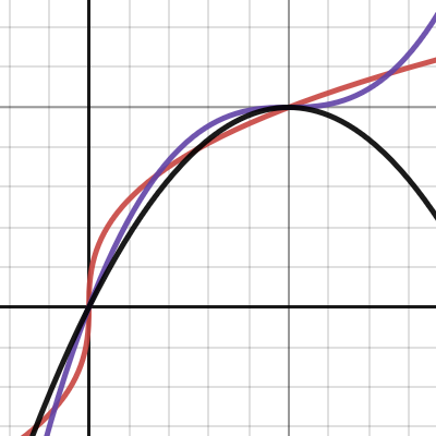
Desmos
or maybe a circle curve?

that was it! thanks a ton
Great resources, thanks for the links ^^
Anybody has worked on Shaders for Custom Render Textures?
i just want to know if the Shader would allow me to tell the Render Texture just to capture 1 fragment of the screen
now seems there's no way of doing that with a rergular Render Texture and reading the docs i came across this Custom Render Texture that accepts shaders
Copy?
See https://docs.unity3d.com/2018.3/Documentation/ScriptReference/Graphics.Blit.html
and the offset and scale params
Oh,thanks ill give a read tothat
sorrry but isnt this exactly the opposite of what I'm trying to achieve? I want to bring a portion of the renderview to a texture, but this seems to do the opposite? or am i missing something?
You can play around with camera matrix
https://docs.unity3d.com/ScriptReference/Camera-projectionMatrix.html
Thank you ill take a look to that too. Okay this looks promising
🙏
when we define 2D Texture properties with any name like _MainTex
we need to define _MainText_ST for tiling information i guess
what does ST stand for ?
Scale & Translate, If I'm not mistaken
this was the result of playing with the camera matrix 🤣

it was a good attempt but seems the projection change distorsions the buildings
i dont understand why happen my camera is orthographic...
GREAT
changed the matrix to ortthographic