#archived-shaders
1 messages · Page 240 of 1
Ok
I dont understand the textures bit
My uv maps are seemingly fine
In blendr
Hm
what do you mean by
The textures go haywire
exactly?
can you show how it looks?
Look at the img i sent
In blender, nothing is white
And its all one object using the same material
Its just one side going white
then the textures did not come with the model or you did not assign them
how did you import the asset
as a blender file or FBX ?
.blend
I downloaded the textures and applied them. Again, fine in blender
But not unity
if i remember correctly only texture that are packed in the blend file will be imported with he model
let me make a quick test
I unpackeed,them
seems like importing it via a blend file will not copy over the texture
i works if you export it as a FBX
here is a guide for that
https://gamedevtraum.com/en/blender-tutorials-and-curiosities/how-to-export-a-3d-model-in-fbx-format-with-textures-in-blender/

When exporting a model in FBX format in Blender, textures are often lost. Here we will see a method to include them in the FBX file.
Thhx
Hey folks, thanks for all this - I'm on Australian time, so have just seen your responses now. Yes I think you're right I can use the Polybrush approach to paint vertex colors, then setup a shader with two colors. Sounds like that will suit my needs perfectly. Thanks for your help!
hello, what type of shaders do I need to create to work with URP? will unlit work fine for me?
That question doesn't really make sense.
URP comes with it's own built in set of shaders, which includes an unlit, no need to create one yourself.
i dont see the option for the simple_lit

how do i create the shader script instead of a graph?
its only giving me options for graps

hey, i recently downloaded a shader for waves but it only works as necessary with their "big plane" and not the one that i can put into unity, any help?
is it possible to make a shader that shows a 3D object with perspective inside of an orthographic camera
if i make a custom camera matrix
what i meant is that I want to create a .shader file type shader for lit surfaces

standard surface type shader
but you can still use an unlit shader for lighting
im new to this, are you sure this will work?
yea
i am using URP for the project
ok, ill try this out
no see, im trying to create a custom sprite-lit type. the unlit one isnt effected by lighting
?
this is effected by lights

i want to create a custom shader just like this one. something from a simple template to change things around.
the only way to create a custom sprite-lit shader is thru a shader graph. I want to instead write out the shader myself
u can't
so then the only way to make it work would be to copy the code from the .shader file and try to translate it to shader graph?
You can make a sprite-lit shader graph and modify the generated code
Much easier than going the other way
Or make a shader graph that uses custom functions
I'm trying to mask out objects from a custom post-process effect (URP render feature, blitting color texture with grayscale shader). I'm using stencil for the first time, so maybe I misunderstood the concept, but I already have setup a shader that renders objects I want to be masked out/excluded from the grayscale effect with this stencil block:
   Stencil
   {
     Ref 2
     Comp Always
     Pass Replace
   }```
And I added this block into the grayscale shader:
Stencil
{
Ref 2
Comp Less
}```
As far as I understand it, this should set 2 into the stencil buffer for each fragment of the object I want to be excluded from the grayscale effect, and then the grayscale shader should not execute for these fragments.
However, it doesn't seem to be working, the masked objects are also grayscaled. I'd like to know what should I look into, what could be the cause. Is the Stencil setup wrong or should I look into something else?
can i get scene color for certain camera in shadergraph, or do i need to write a shader/ use custom render feature/rendertexture?
render texture would be easiest
i basically want to get the material color of objects above a certain height before rendering opaques. then make a part of the top layer mesh invisible so i can have different mesh shape but with the same texture (like a vertex displacement shader, but with another object. for example: hole in the ground) .
but this requires another camera -> slower performance
not if you optimize it
what do you mean? how to optimize?
via scripting?
sure
but one problem could be: having the camera cover a large range could result in to low pixelcount. but i will try. thanks for youre help!
but how do i get the worldspace coordinates of the rendertexture so i only use the cutout of the rendertexture relating to the object position of which i want to put the rendertexture material? do i need raycast at the cameras border points? i cant define a camera in shadergraphs camera property-> its always the main camera
what
it's just a texture
make a texture2d property and edit the rt in the shader
maybe this helps to understand my issue. thats a rendertexture from a camera thats a clone from my main camera

i want the mesh to look like a cutout from the rendertexture, i dont want to spread the complete texture over the object
Hey, is it possible to deform mesh with a shader ?
like, i made a shader on blender and i want to try recreating the same in unity but i don't see something to deform the mesh directly from the shader
this is my blender animation, the center is just a sphere and i add multiple shader to make it moove like this
i just wanted to know if it's possible or not

Download the demo project here: https://ole.unity.com/sgvertex
To learn more about Unity, check out some of our available courses on our Learn website: https://ole.unity.com/unitycourses
To check out some other cool effects, feel free to also browse the Unity Asset Store: https://ole.unity.com/MeshEffects
If you prefer a written article versi...
ty !
Is there a cross product equivalent for 4d vectors?
Ok so i have change the mesh of my sphere using shader but now i doesnt look like a sphere at all ? and i don't really know how do i change this


might need more vertices
Any clue on how to make the background of this texture transparent? The png is transparent but the ingame texture isnt

Nvm
The material has to be set to transparent
Other processes (like lighting) may be using other bits, or even that same bit. So you should investigate the mask attribute (ReadMask WriteMask) to use a bit mask and figure out what bit to use in your stencil. Maybe also try comparison of Equal or NotEqual. I don't remember off the top of my head what bits are available for which pipelines.
I cant figure out why the decal is not on the door on import. On blender it works fine...


If it's a raw import, maybe it didn't import the materials properly. Have you tried making a new material and applying it to the object? If not, maybe show the settings from the Material. And the imported texture. Maybe the alpha isn't set up right.
Everything else has imported properly except for this. The textures and material seem okay to me. If you want to see the blender materials, tell me


All good. But wait, what pipeline is this? I see you've set a Standard Shader there for the material. I've only messed with URP.
And the built-in pipeline a while ago. Lemme check.
Nice. Dumb question: Did you actually drop the material onto the plane? lol

Nice, alright. Well, what's weird is that even in the material preview it's still gray. Should be transparent with only the decal on it.
Oh, yeah, nevermind then. lol
it works fine
its just the door decal
Oh
Its on the wrong side?
I set the top material to transparent

Aha, lmao.

Do i flip this in blender
Well, I would've suggested to try out different shaders for the decal material but it's fine now. We know why it didn't work. lol
You could just flip the plane.
You could either flip the UVs, or adjust the rotation of the mesh in Unity or you could invert the texture quickly.
I think this might be the issue where blender has different axis than Unity. So sometimes stuff is flipped.
Yeah, flipping normals ain't it. It's the UVS you could scale on X to -1 in blender. Or as I've said, just use the rotation tool in unity and rotate the plane by 180 on Y.
Yes. In URP (assuming you're using that pipeline) you get the scene color with the scene color node. You have to activate the "grab texture" that happens between the opaque and transparent passes, and you'd use your shader in the TRANSPARENT queue, since it needs the opaque texture to have been grabbed, otherwise you'll just get grey.
Activate the grab for the camera in the camera's settings, or for all cameras in the render pipeline asset. If for some reason it doesn't work just activating it on the camera, you'd have to use the asset to activate it (IDK why that would be necessary, but...maybe you want that).
I'd recommend next time you're in blender to make a new FBX exporter preset where the axis are set up properly so you don't need to deal with flipped meshes and stuff in Unity.
Alternate solution here: Put up your cube with the gray material and then add a plane with just the decal material on it.
I personally I like to make decals just planes so I can swap them easily as well, plus rescaling works a lot easier.
Cuz it works fine in blender
plus, if i wrap a decal next time, i cant use a plane
ill try
check your normals in blender and enable the normals direction view in edit mode
otherwise you can use probuilder in unity to flip normals
How tf do you remove a material again 💀


Where is it located
Oh
that setting
Yea but everything seems fine
God I hate unity's tomfoolery with normals
as i said: you can use probuilder to flip normals. unity has a normals view as well
But flipping normals wouldn't work as I said
Because it would make the door look wierd
and inside out and stuff
I just want the material applied outside not in
then assign 2 materials in blender

add another plane for the inside/outside, or extrude. then create a new material, assign it to the side and export


In this tutorial I will show you how to assign materials in Blender 2.8. If you are just starting out on learning Blender this is a really good software to learn on. I hope you found this video is useful, if you did give us a thumbs up! Thanks!! :) Here is a link to download Blender 2.8: https://www.blender.org/2-8/
Ik how to assign
i dont know what your problem is but it seems that you dont have created smart uv project for the other side of the mesh
Hmm
I made a uv map for
it
I think that may actually be the solution
I think HDRP natively supports decals, you'd do well figuring that out in a test-project first, as you're spinning your wheels if you're not using HDRP's system from the start. 2-cents.
For URP, you can use something like this:
https://www.youtube.com/watch?v=f7iO9ernEmM
For HDRP see this:
https://learn.unity.com/tutorial/hdrp-decal-projector#
Again, just my 2 cents, and sorry for butting in, I may not have followed all this conversation.

Decals have been available natively in HDRP for a while now, but not URP. Luckily, there are ways to add our own. In this tutorial, learn how to use some neat tricks involving space transformations and the depth buffer to make decals of our own which project a texture onto flat or curved surfaces!
✨ Based on NiloCat's fantastic impl...

Unity Learn
One component of HDRP is the Decal Projector. This casts an image onto objects in a Scene. In this tutorial, you will learn how to use the decal projector to project an image onto objects in a Scene.
thx
This worked thx

np
hey, am i able to reduce the ammount of effect for this sphere ? my mesh is too deformed and idk what to do can i just reduce the noisescale ?

Hey guys, I just tried painting some displacement map in photoshop and imported it into unity to try it out in the standard and tessellation shader respectively. Here's a short clip on how it looks:
https://youtu.be/f3nkGMoEs3A

Here is a quick video showing how we can paint displacement maps in Photoshop and bring them in Unity. First part video shows the Unity's simple standard shader with Diffuse, Normal and Height map.
The second part of the video shows a tessellation based shader with the exact same maps.
This is the difference you can make with tessellation shader...
Howazattt?
After some investigation, the stencil seems to be working fine. If I place an object with shader writing to the stencil buffer and then place another object before it with the grayscale material, the desired effect is there - overlapping object is not rendering fragments that were masked out. However, I cant get the same result when applying this to a fullscreen effect. So I reckon I'm doing something wrong with the final rendering, as the stencil itself seems to be working
I'd say it has something to do with the usage of Blit in the renderer feature I'm using
i have a problem, i want to change the size of my outline but it isnt working at all. Like my outline isnt showing for some reason its in the model but cant get out

is it possible to make a shader that shows a 3D object with perspective inside of an orthographic camera
if i make a custom camera matrix
Anyone know why the metal of the door has such even and strange lighting compared to the decal?

Like, the cornel of that room will be almost pitch black but the door will still be alight
corner
as long as some light interacts with it
Is it to do with this?

hello can someone tell me how to apply alpha masks on a shader? I am trying to apply it on my character model so the skin won't clip through the clothes.
either prepare in the UV 1 propper uvs for lightmapping or enable the generate lightmap uv option in the models importer
Alpha masking/alpha clipping is done in the opaque queue, by setting the alpha value in shader graph to whatever the mask or alpha-channel value is, and then setting the clip threshold such that any value under that threshold causes the pixel to be clipped.
IDK what pipeline you're in, so if in hand-written BiRP you'd use the clip() function as in
clip(threshold - myAlpha);
but in Shader Graph there's a built-in process for that in the fragment stack. See graph settings, you have to enable alpha clip.
Hey, I just realized that the default Lit shader looks way better then my custom one from Shader Graph 😛 I have to use a custom one to implement some stuff for my game, but the "default" state should be the Default Lit URP Shader... is it normal that a custom one already looks different from that? And is there somewhere a Shader Graph Version of the default one to customize?
Example, Left one is the default lit shader, right one is mine (basicly just base color in this case with some specular)

Colors on both shaders are the same, so left (default) is doing definetly sth special.
You can download the built in shaders from the download archive. I don't think they have shadergraph versions, but you can see the code. Maybe compare the generated code from your graph to their code to see what's different. https://unity3d.com/get-unity/download/archive

Unity
Unity is the ultimate game development platform. Use Unity to build high-quality 3D and 2D games, deploy them across mobile, desktop, VR/AR, consoles or the Web, and connect with loyal and enthusiastic players and customers.
Found those already, and hoped there is a simpler / shader graph based answer for it 😛 Thought this is a general problem, since it sounds strange that basicly any object I want to do some custom shading on, will look significantly different from everything using default lit shader :/
i didnt se anyone answer this, but yes. have some kind of variable that changes the amplitude
How do I use functions from one HLSL file (.hlsl) in another (.compute)? I've tried using #include but it doesn't seem to work.
How/where did you use it? Show code. What error message did you get?
Ok one sec
My Code:
WhiteNoise3D.hlsl
#include "NoiseUtils.hlsl"

void WhiteNoise3D_float(float3 input, out float Out)
{
    Out = rand3dTo1d(input);
}
TerrainGenerator.compute
#include "Subgraphs/Scripts/WhiteNoise3D.hlsl"
#pragma kernel Main

[numthreads(64,1,1)]
void Main(uint3 id : SV_DispatchThreadID)
{
  int i = 0;
  WhiteNoise3D_float(float3(1, 1, 1), out i);
}
My Error:

Could it be because I'm trying to use out?
I tried switching "i" to a float and it didn't fix it.
I think when you call the funciton you don't use out
only when you declare it
I'll try it
Wow it works lol, thanks
yeah that tripped me up the first time coming from C# to HLSL. since you need it in both places in C#
Well, the good news is that #include works.
He beat me to it! lol
I have another question aswell
This is from the Noise Utils file:
#ifndef _INCLUDE_NOISEUTILS_
#define _INCLUDE_NOISEUTILS_
I didn't make this code, I got it off github, what does ifndef and define mean? It seems to relate to include but I dont need that in any files I want to include right?
It stops it from being accidentally included twice, generating an error.
Oh ok, thanks
So if you accidentally include it twice, the 2nd (or 3rd...) time will be ignored.
does anyone know a good way to make a lit shader for smoke particles where you see the light from both sides (the light passing through the smoke)? or is there another option that achieves this?
It can be accomplished with (A) blended transparency to a point and/or (B) volumetrics (which is more complicated). Research things like volumetric fog or smoke. Hint: it's a lot like ray tracing/marching, through a volume and computing density and various lights going through it.
yeah, I really didn't want to do volumetrics because I have no idea how to do that stuff
can you clarify what you mean by blended transparency to a point?
Have you tried it with just stacking transparent objects? You'll see the limitations.
Also, beware of overdraw, it is a killer with tons of particles.
I had a situation where a projectile had smoke trials and came AT the player from afar. Stacked a poo load of particles on top of each other. Almost needless to say, but that approach was not a good way to do it.
I ended up doing something with various dithering levels instead.
well even with stacking transparent objects, they don't receive lighting from the other side
OK, so you want an actual LIGHT to impact the particles? Yeah, you'll need to at least iterate through the lights and compute something, and you're getting into some kind of volumetric calcs if you want it to look more-dense and less-dense in various places.
that's what I wrote
Transparents would only get "light" from the background that "shows through". Like the color buffer contents, not a light ray.
A super basic way to do this is to write custom lighting that doesn't include N dot L as part of the attenuation or reduces it significantly
ok hold on let me give you an example
Well, what was wrong with that?
you were asking if I wanted light to impact the particles, I was just reiterating
doesn't include N dot L as part of the attenuation
now what in tarnation does that mean lol

N dot L is what gives you the basic lambert/diffuse lighting. The faces that are facing the light source get more light.
But because particles always the camera, that doesn't really work, so you can instead just ignore this part of lighting calculation and just use the distance to the light if it's a point light
yeah that sounds good
For directional lights, it would always contribute the same amount of lighting regardless of direction
N is the surface normal. L is the light direction.
But you're largely ignoring that, in MS's solution.
The problem is
That you cannot tell how many OTHER particles are blocking between the current one you're processing and the light.
So you cannot get attenuation.
And as a result you get a bunch of same-shaded tennis balls, for example all clumped up. And if that's what you are OK with, cool.
You can use a normal map on the particles to give them some degree of visual depth.
If they're large.
yeah, I don't want a realistic volumetric effect
How can i add these field to into this shader if I put anywjere it gives error ##pragma multi_compile_instancing ```Shader "Mobile/Particles/Alpha Blended"
{
Properties
{
    _MainTex ("Particle Texture", 2D) = "white" {}
}

Category
{
    Tags { "Queue"="Transparent" "IgnoreProjector"="True" "RenderType"="Transparent" "PreviewType"="Plane" }
    Blend SrcAlpha OneMinusSrcAlpha
    Cull Off Lighting Off ZWrite Off Fog { Color (0,0,0,0) }

    BindChannels {
        Bind "Color", color
        Bind "Vertex", vertex
        Bind "TexCoord", texcoord
    }

    SubShader {
        Pass {
            SetTexture [_MainTex] {
                combine texture * primary
            }
        }
    }
}
} ```
First it has 2 hashtags which is wrong. Secondly you can add it in the sunshader
it gives

i fixed it but there is no option to open Instancing


Guys, I was wondering if we can write a geometry shader node for the shadergraph in URP?
So that it directly works with the standard shader.
help?
Sorry no idea, others can help fingers crossed 🤞
Anyone know how to fill a buffer or a texture with triangle id's and have a hdrp shader read that and compare its current triangle id with that buffer/texture. I dont want to read the data back to the cpu and use drawprocedural
One way would be to create the buffer from the model(s), and then stuff an index into the vertex attributes of the mesh, so each polygon knows its index.
Hmmm add a bake phase at editor time huh ?
Isnt there like a SV target triangle id something I can use on shader model 5.0
Hello guys! So I made a simple shader that gives my sprite a green outline. But when I apply it to my sprite, all the transparent area of the sprite becomes black. What can I do to fix this?

Show the shader
don't know if you can see it since it's kinda big

it's happen in other shader too

You need to pass a alpha value
And set your shader to transperant or alpha cutoff
The A from your sample texture contains the original alpha
Add that to the outline before coloring it and pass that to the alpha chanel in the fragment stage
okay, i will try it
System-generated values are generated by the IA stage (based on user-supplied input semantics) to allow certain efficiencies in shader operations.
Good luck with that though, looks like several potential issues, in particular instancing, but IDK what you're up to.
Im trying to make a renderer with drawinstanced indirect that also has per triangle gpu culling
I have most stagea down on a conceptual level but cant seem to figure out how to connect the triangle viz data to the shader so normal hdrp rendering can continue from there
thank you it works wonderfully!
No probs
hey i havez a shader that is switched by an other version of it during runtime. On editor it work fine but on build it became magenta. Any idea
Couple of things the shader requires things that are not supported on the target platform. Or a material using the shader is not present in any scene at build time causing the shader to not get build in. Check your logs of the build for details
there is no materials, i basically do
 Shader cShader = material.shader;
        material.shader = transparent;
        Color Tcolor = material.GetColor("Tint");
        Color color = material.GetColor("Tint");
        Tcolor.a = 0.1f;
        material.SetColor("Tint", Tcolor);
        yield return new WaitForEndOfFrame();
        material.shader = cShader;
        material.SetColor("Tint", color);
yield return null;```How are there no materials if you do material.shader ?🤣
i mean, it's the basic material of the basic shader; i do not understand why it work on editor and not on build
😢
Because
Probably the transparent variant
Did not get build in
Because it is not present in any scene
I have no idea what your transparent variable holds
how can i force to be on the build ?

You can be sneaky and place a disabled object with that shader in a scene
So it gets build in
But the proper way is a shader variant collection
Guys I'm having a problem with enums in My shader
I Created an Enum _Fx

I've set it as uniform float

but it won't enter my if statment

what am I missing?
Hey yall, Can somebody explain to me when I use the Parallax Occlusion mapping node and I change the UV in from UV0 to UV1 it breaks my shader?

hey is there a up to date tutorial for this style of shader ? https://www.youtube.com/watch?v=DpXPhGeCqus
In this video we will show you how to create Magical Plasma Orb using Shader Graph in Unity engine.
Download project files (Patrons only): https://www.patreon.com/BinaryLunar
00:00 Intro.
01:00 Setting up the project and the scene.
02:50 Transparency Rendering in Shader Graph.
04:25 Creating scrolling texture nodes.
07:15 Creating surface move...
For that exact style? Probably not
Thought the shader graph UI has been reorganized, few tutorials have become incompatible as a result of changes
newbie shader question, Surface Shader, what is Metallic changing? I'd think metallic-ness would be glossiness, but- well it ain't so :P
Also, what language is the .shader file?
Metallic workflow is a whole topic of its own but mainly it determines if base color should tint specular reflections
What about my colors? It seems they're a bit bright- or faded? If I turn them to be darker, the look right however
That's entirely dependent on the lighting, color space and possible post processing
Cant see what im doing wrong here, the top of the cylinder is supposed to be clear not gray.
Lit shader, surface set to transparent, alpha set correctly... turning on alpha clip just makes it all gray which is somewhat expected. Thoughts?

(reposted to remove client logo haha)
I don't spot any obvious issues but it might be clearer to use the height gradient as alpha and use a solid color for emission and base color
Since the gradient works already, using it as alpha directly should make that work as well
And if you use the gradient as color as well you'll get greyish haze where it fades out
im starting to think that texture warping or vertex snapping isn't possible in shader graph
object space gradient, fed directly to alpha. Solid color directly into Base Color, still seeing it. Havent had this issue before, very weird

so im gonna ask once again, how do i go about making ps1 style effects in shader graph? mainly texture warping and vertex snapping.
I've seen pretty amazing feats performed with SG, but for what you're trying to do there's certainly no nodes ready to go
You'd have to know like, shader maths and stuff
I still don't see anything wrong but that rules out problems iwth the color inputs at least
Can you make it transparent at all if you drop the nodes entirely?
nope, just goes solid grey
its like its already got a mat and im just adding another one, but i checked that
tried changing the blend from alpha, all give the same result
alpha clip just makes it a hard cut from white to grey
right?
Gonna check what URP im running
10.4, last verified so that should be fine
Could try restarting the editor
If there's something broken, or some overlay stuck on
mm true, ill give it a go
Thanks for the rubberducking btw
still grey post restart
oh my god im an idiot
there were two cylinders there

fuuuuuuck thats the worst one ive done in a while
it happens 😂
Spent my day teaching juniors, they should not listen to a word I say haha
thanks for the help man
i did find a texture warping tutorial but its shader writing, not shader graph, is there any way i can convert it to graph?

a picture from a video
Hi, I've been dabbling in shader stuff on and off for a bit and I'm trying to practice more to add it to my resume. I mostly been training on single shader files and I was wondering how one would go around putting utility functions and the like in separate files for use in multiple shaders in a production environment.
found a cool bug on M1 macs - there are some cases when sampling a fixed-size array where an out of bounds error is not handled, but rather than erroring out (as it will most of the time) it actually just soft locks the editor
I'm still trying to produce a minimal example, but can't - any simple implementation unity seems able to detect the OOB and fail to compile the shader
however, this error has been giving me grief for weeks and I'm glad to finally catch it - literally just need to put index = clamp(index, 0, 15) before sampling my dither patterns and it doesnt crash on M1 macs anymore
You can download Unity's built in shaders from the download archive. They are a great example of how to split stuff out between files.
Shader error in 'raytracingShader': unrecognized identifier 'INVALID_UTF8_STRING' at kernel RTMain at raytracingShader.compute(1) (on d3d11)
Anyone knows what this could be caused by? it suddenly appeared and it seems that now the compiler is taking offense at the # character that I need to define a kernel
is this directive illegal in some conditions ? "#pragma kernel RTMain" (error is the same if use a bogus name for the kernel).
New compute shaders are also created with this error
Found the issue. I was using "²" in one of my comment and the compiler couldn't handle it
Is there a specific reason why texture near camera seems pixelated ? But away from cam is quite nice n sharp
In trying to figure out what to call the technique where a texture index is encoded into another smaller texture. The pixel would get looked up and depending on say the green color, it would map a specific texture to the model
Can you send an example?
yeah i noticed that but how can i made a shader look like this old tutorial ?
I would start by trying to follow the old tutorial 🤔
yeah that's what i was gonna do but i already follow 2 tutorial of 1hours and finally didnt working because of out of date version  and this tutorial is kinda long
What specifically about it didn't work?
https://www.youtube.com/watch?v=QsLkb1aOkb8&t=116s i was following this tutorial i did everything good in the tutorial and finally i got just a sphere scaling up and down the size @grizzled bolt
In this video, we will show you how to create a Ripple Wave Vertex Shader Graph using Unity 2021 URP.
Download project files (Patrons Only): https://www.patreon.com/BinaryLunar
00:00 Intro
00:55 Project overview
01:47 Ripple Wave Shader Graph overview
03:10 Creating ripple origin
03:44 Creating ripple density nodes
04:40 Creating ripple freque...
using HLSL how would I take all of the verticles, and say using any form of noise randomly displace their vertices to create a sort of glitching effect as if the model was broken? Can anyone help?
does anyone know why my textures are acting all weird?

Looks like weird normals on the mesh, making the light reflect inaccurately.
it ist
i fixed it
im stupid i was exporting the mesh with the light
and i dont want a shadow map for the mesh
How do I make a Voronoi outline in the shader graph?
getting this result and i can't tighten it without it getting rounded off

while i'm trying to achieve something more like this

i know blender has a voronoi crackle that does this but i'm trying to create the effect in Unity
Anyone have a good textbook/course recommendation for learning shader programming?
https://learn.jettelly.com/unity-shader-bible/
You could check this out

Introduction to the shader programming language.
Does this cover matrices?
I need a resource that teaches matrices in an easy to understand way
The catlike coding tutorial is too hard for me
i plugged it into an if node with a paramater named "if_true_then_make_lines_sharp" but it's not doing anything

Try the step node
that just makes a bunch of circles
Then use one minus node
now the circles are black instead of white
After using step?

Mess with the voronol settings
they only change size and grid randomness
If we could make polygons instead of circles that would fix it
Might require some math tho
cells does that but, well take a look


it creates the polygons but differntiates them by 0-1 values, instead of distance to edge
@wide thicket From what I understand you'd have to do math with the points originally used to generate the voronoi pattern, something we don't have access to with the node
i got it to work, had to run the cell through a sphere node, then layered it like 5 times with an offset to create a line
it's heavy but it works
Hello. Can anyone help me with this? I don't know what's going on or maybe it's from the settings. It happens when I put a shader for Occlusion.
In .gif is a VR Shader> SpatialMapping> Occlusion.
- Android * URP*

hey can i dm you i have some questions idk if you know a lot about shader
It's better to ask questions here
okok so i wanted to know how and if it was possible to recreate the same shader that i've made in blender but this time in unity ? Even if it's not exatly the same but something close ? I already whatch lot of tutorial but lot of them are out of date ... Ty for your time it will be appreciated
Sure it's possible but there are no shortcuts to learning the Unity side of shaders
ty our school no formation for unity and had to make shader
it's why i watch a lot of tutorials but at the end the shader didn't work properly
do you have idk keywords i can search for this kind of shader
You've already been looking at the kind of vertex displacement shader tutorials you need for the effect so I'm not sure what else could help you 🤔
Besides more practice so the systems become familiar
If you suspect they don't work due to editor version mismatch, you can try following the tutorials on an old version, or try finding tutorials for a new version
In time any problems arising from that become solvable to you
in my original shader in blender i used voronoi but in unity i don't think it's the same think
i can't work on another version i have a whole github project working on it with the last version
You can install a new editor and make a new project for testing, I do it a lot
and the shader will still work when i export in the new version ?
Blender does multi-dimensional voronoi, shader graph's is 2D by default so they don't work exactly the same
I can't possibly promise that 😄
sad
i will try edit and redit the properties of the vertex shaders
it's only with the NoiseScale that i can edit the number of polygons etc ?

it's kinda of the movements
but too big
Anyone know how to work around the issue of one side of a plane being in shadows, when using a double sided shader?
Does anyone know why is my car texture stretching on the sides like this ? I'm following brackeys tutorial about dissolve shader

The parts that are transparent in the alpha channel will be stretched to save file size and avoid color bleeding
You'll probably want to multiply the texture's alpha with the noise before plugging the result into Combine
Or plug the multiply result directly into alpha, that works as well
so how to fix this
um
Ok i fixed it
I ran into the same voronoi issue from blender, so if you want 3d noise in Unity install this package:
https://github.com/JimmyCushnie/Noisy-Nodes

GitHub
Adds various noise generation nodes to Unity Shader Graph, including 3D noise nodes. - GitHub - JimmyCushnie/Noisy-Nodes: Adds various noise generation nodes to Unity Shader Graph, including 3D noi...
Does anyone know where this comes from. Got these errors out of the blue in my console.


Hi all , is there any pdf or similar to read up about shaders and understand them better ?
Surely many, tough it's an absolutely massive topic
If you want a beginner friendly thing that's relevant to game asset creation you could start with these
https://halisavakis.com/shaderquest-part-1-graphics-concepts/
https://www.cyanilux.com/tutorials/intro-to-shaders/
definetely beginner friendly 😄 Thank you a lot for answer
hey i made a new cube sphere in blender and import him in gltf for unity, i create a lot of polygons but i doesnt seems that unity detect them

it seems like for unity my polygons are gone

do you do vertex offset via shader?
nop
why is the lower image so distorted?

the issue seem that you are doing it based on some noise that is using the UV map of the sphere
but there are UV seams that cause hard corners
you would either need to have a uv map without seams or use some other source for UV like object coordinates or world coordinates
i don't really understand sorry
in the mesh is information that determines how the texture is mapped on it.
but not the whole sphere is in one nice piec so there is a seam where the texture is not so nicly cut of
imagine how you would wrap a present or package with some textured paper there will be places where the paper ends and another piec of the paer with some other texture does not meet exacty fitting
you can put the UV map output into the color output of the shader to see what i mean
in my case, the UV map output is this ?

and how can i put my UV map outside the shader, ? in another shader ?
I need a resource that teaches matrices in an easy to understand way
The catlike coding tutorial is too hard for me


Is there a way to access an AppendStructuredBuffer<Type> from a kernel inside the same compute shader? Unity complains when I try to index to it like any other buffer and *surely you dont have to make a handover on the CPU side of things just to throw the same data back... right? that would be stupid  *
*
AppendStructuredBuffer<half3> Positions;

void SetupKernel(uint3 id : SV_DispatchThreadID) {
  append to Positions;
}

void Access(uint3 id : SV_DispatchThreadID) {
  Positions[id.x] <- this is what im trying to do
}
maybe its not possible with the nature of the type of buffer, all I hope is I dont have to move as much data as that buffer holds across twice per frame :/
Hey I have kind of a newb question, but is there a way I can toggle between color mask modes?
say I want to be able to switch between colormask rgb and colormask rgba without editing the shader file ?
of course as soon as I ask I find an answer to my question (i think)
yep, all good, nevermind
Just started learning about Shader Graph today, and I see on a bunch of videos they're using the PBR master which has options like alpha, and Metallic which don't seem to be on the Vertex-Fragment one. Any idea where I can find these?
PBR master is now called Lit graph and should have metallicness input visible by default
Other things like alpha may need to be enabled from graph settings now
oh i found it tysm
Big dumb idiot here. Trying to make a face that you can control the skintone of. Threw in eyes into my shader, but having trouble with 2 things:
How can I make the texture's UV's stay transparent? ("Alpha Is Transparent" seems to override the whole material and make everything that isn't the decal alpha.)
How can I layer the decal (is there a proper word for it?) over the skin shader without using multiply? The Photoshop vocabulary for this would be a "Normal Blending Mode" but obviously that means something completely different here
Edit: Okay I see that it's Blend, with the Overwrite mode selected, but is that makes it such that my materials using the same shader (without the texture) turn white. Is there a way to set a SerializedField (or whatever it's called) to ignore a certain node/fork if a material doesn't have a texture?
You could use a boolean with a branch to disable the blend node conditionally
Or maybe an easier solution is to make an exposed float property which controls the opacity of the blend node and defaults to 0 or 1, whichever makes the blending invisible
"Alpha is transparency" doesn't change the alpha (or transparency) of the texture at all, rather it dilates colors outwards to prevent fringing artifacts when the texture is used with alpha
Thanks! I think I understood about 95% of that! Appreciate it man
The append/consume buffers are intended to function like a stack. One kernel would append, and another would consume, maybe across frames.
If you want to index into a buffer, just use plain everyday RWStructuredBuffer and keep track of your index.
Remember you can stuff results into another small buffer, and read that small buffer back. That's really what append/consume buffers do...there's an associated small data structure keeping track of the current "stack pointer" for the buffer.
All the above is classified as "I think" and IIUC, and worth about 2-cents. 😉
Didnt think about the names as an actual usage medium I guess that makes sense (I couldnt figure out the difference between an append and consume buffer since it isnt well documented) The amount of data in that buffer varies greatly from having 100 half3's to up to millions, so allocating a compute buffer in runtime sounds like a pain in which I may be keeping the append system. So I would use both an append and consume buffer and bind the same buffer across both layouts? if so then I understand
does anybody know how can I make a depth test in shader graph?
I'm changing the Ztest value but nothing changes on my game. Thanks in advance

Hello, I have some (basic I suppose) troubles with compute shaders
I copied the TMP one to add a noise dissolve, but I can't seem to influence it directly.
_NoiseIntensity ("Noise Intensity", Float) = 0 added to the Properties
float alpha = input.color.a;
if (snoise(input.atlas) < _NoiseIntensity) alpha = 0;

return faceColor * alpha;
at the end
I also added uniform float _NoiseIntensity; before the functions
I edit the value in code using Shader.PropertyToID("Noise Intensity") and I use a noise library that I tested before, that works (noises are between 1 and 0)
Update, it says that it's the default material and shaders, even tho TMP use custom shaders and that I copied one to replace it correctly
what's the best way to make an outline without having to instantiate a lot of materials for each different object?
Hello !
I have a problem, I want to basically shade my screen to black in vr using this shader, but it doesn't work : Only one eye become black.
Does someone could help me, please ?
    Properties
    {
       _worldDirection("World Direction", Vector) = (0,0,0,0)
       _power("Power",Float) = 1
    }

    Category {
    Tags { "Queue"="Transparent" "IgnoreProjector"="True" "RenderType"="Transparent" }
    Blend SrcAlpha OneMinusSrcAlpha
    Lighting Off ZWrite Off

    SubShader {
        Pass {

            CGPROGRAM
            #pragma vertex vert
            #pragma fragment frag

            #include "UnityCG.cginc"

            half3 _worldDirection;
            half _power;


            struct v2f {
                float4 vertex : SV_POSITION;
                float4 color : COLOR;
                float3 viewDir : TEXCOORD0;

                //vr single pass
                UNITY_VERTEX_INPUT_INSTANCE_ID
                    UNITY_VERTEX_OUTPUT_STEREO
            };

            v2f vert (appdata_full v)
            {
                v2f o;


                //vr single pass
                UNITY_SETUP_INSTANCE_ID(v);
                UNITY_INITIALIZE_OUTPUT(v2f, o);
                UNITY_INITIALIZE_VERTEX_OUTPUT_STEREO(o);

                o.vertex = UnityObjectToClipPos(v.vertex);
                o.color = v.color;
                half3 worldPos = mul(unity_ObjectToWorld, v.vertex);
                o.viewDir = normalize( mul((float3x3)unity_CameraToWorld, float3(0,0,1)) );
                return o;
            }

            fixed4 frag (v2f i) : SV_Target
            {
                //vr single pass
                UNITY_SETUP_STEREO_EYE_INDEX_POST_VERTEX(i);
                float dotView = clamp( dot( normalize(_worldDirection), i.viewDir ), 0.,1.);

                float4 color = lerp(i.color, float4(0.,0.,0.,0.), pow(dotView, _power) );

                return color;
            }
            ENDCG
        }
    }
}
}```There is the custom pass if <i remember correctly, try searching about that :)
how do i use this texture 2d as a normal map??

is anyone is familiar with deferred rendering path under urp ? i do not understand why despite my shader (made using shader graph) is fully black i have a lighting
I figured mine out, I had to use _tmp.materialForRendering instead of _tmp.material. If it can help anyone
The Normal output in the Vertex Stage is for setting the normal of the vertex
If you wan to use a normal map it should be go into the Normal Output of the Fragment Stage
you still need to sample the texture first

ahhhh thank you
how can i turn the output of this slerp node blurry or into a blurry low res image?? i just want it to look blurry

That's the step node, not "slerp", which creates very sharp transitions
There aren't many ways to blur things, so it's better to find another way
Yea my bad,i meant step
https://youtu.be/2I06F7g4b8Y?t=26
Anyone knows how this skybox effect is working? I am not familiar with this 2d things.

Hey so I’m currently using a compute shader to pathtrace in real time and it’s working, but I wanna see the performance comparison to using rtx hardware, is it possible to use raytracing shaders that use RTX hardware in place of the traversal kernels I have in the compute shader for intersection data, while still using the other kernels in the compute shader(for materials and such)?
Ok so how do I get it where I can draw a boundary where an object touches something else. I have to compare depth textures somehow, right?
Can anyone help me with outline shader I took from the Internet? The problem is that I get the outline but the object becomes dyed to the color listed in the shader as main color. I would like to have the natural color. https://pastebin.com/FpCa0Sew
Pastebin
Pastebin.com is the number one paste tool since 2002. Pastebin is a website where you can store text online for a set period of time.

Assign the texture component to the object's texture (that's what gives the natural color around parts of the object). Unless it's a solid color object, if so , just assign a different color to Main Color. That's the tint. White would leave the texture colors unchanged.
It depends on how the model is set up. If it's using vertex colors, for example, you'd have to change the shader to use them.
💀
hey, can someone explain me how to color this voronoi gradient ?

i tried adding a color but i doesnt seems to apply to the base color
Multiply it by the tint color
Can you do it in my stead please? I am complete noob with shaders
I don't have the texture.
What is is supposed to look like?
1min
like this ? i don't really know were to put it

See where it says (base) and there's a blank texture box? Click on that and add the texture (assuming there is supposed to be one).
Outline shader is the second one. The character looks like this after the first material's processing

I can barely read that, but, take the gray scale result of the voronoi and multiply it by some tint color you put on the blackboard or whatever color you want to use. Plug that into base color.
Hi, does anyone know how to apply a subsurface scattering map to a material? I've got it on a (B) channel but I can't find a map here to slot it in.

like that ? or i need to put the multiple after the voronoi gradient ?

The latter.
Don't multiply a tiling and offset (that's a UV thing) by a color.
The voronoi is a grey scale value, 0 to 1. So if you want to tint that result (that was your question as I understand it)...you multiply the voronoi result (0 to 1) by a color, and you scale that color according to the voronoi pattern.
okok i find out !
ty !
ok now i have another question
i made a sphere in blender with lot of polygons
and when i import in unity all my polygons are gone
idk why
Maybe it is importing quads instead of triangles.
Go back to blender and fix the model to be triangles, that's the best way. IIRC there's a triangulate function/process. Google it.
like this, idk if you see my problem
i want it to have a more spheric shape while moving
it's my base sphere

CarpeFunSoftware can you please answer the question I had? You asked how my object was supposed to look and I provided a screenshot
OK, and that comes from a texture or what?
i will try
Um... I guess the texture is provided to material as main color
Albedo map*
Right, it's called "Base" and there's the tiling/offset and the slot for the texture.
You showed me the outline material, but in that one (probably a 2nd material?) you didn't have a texture.
You may not need a 2nd material at all, BTW. Not sure.
The first is a so called "Standard" shader
Show me that one (material for the object).

hmm i doesnt seems to work either

OK, see? There's a texture assigned to it in albedo. Try plugging that texture into "Base" on your outline material.
The texture slot.
Is there such?

See that square under the white and red boxes? Where it says "none, texture".
Click "select" and pick the same texture as in the 1st material.
The polygons are definitely all there as we can see here
Rather you're fundamentally misunderstanding a lot of what's happening with your shader


Well, that's closer. lol. At least you have some greens and blues. 😉
BUT, this outline shader isn't the same as the "standard" shader.
In that material you have an emission setting, and maybe other things going on with lighting. And it's orange in the 1st one.
Yeah, there is a color which is also applied
I tried to move it to the new material but...

The two shaders just don't work the same.
You could try clipping the pixels for anything that isn't an outline part. Maybe ONLY do the outline part, and leave the other part from the 1st material pass.
It would be nice
So try commenting out passes in your shader until it works or all fails.
It is going to be hard work...
The passes that do the outline are labeled "OUTLINE"...
There are only 2 passes
And I commented both of them
This way I deleted the outline
But the bones are still white
The OUTLINE ones are the ones you keep.
I know
But there are no more passes
But the bones are still white
So the shader still affects the texture passed by the first shader
IDK, I'd have to pull it up, get some model, make a test case with a standard material, your outline shader, and then figure it all out.
I got you as far as filling in the required field for the texture color.
But you have to realize that you can't just plug in one outline material shader over top of another and expect it to work unless it is designed to NOT modify the original object's 1st draw.
Have you seen the standard shader?
No
But I guess I can find its code
The bigger problem is how to add outline to it
Or alter your shader to be more standard-like.
Either way you're biting off a lot. Just FYI.
If you're new
But the outline shader is using a surface shader which really defaults to a standard-like shader if you set things like metallic, and emission and such.
I mostly do HLSL, but I write shaders. But I'm not open for a small contract right now. You can try unity connect/forum or whatever they call it these days.
I was just interested whether it takes a lot of time to learn how to make shaders like outline shader
There's at least 5 ways to make an outline, probably 5000 variants. And that's just one concept.
You look like a shader guy

So usually you just google about the graphics effect you want?
Well, that's a good place to start, unless you're inventing something new. Outlines come up every other day here, but you're asking a specific question on a specific shader you pasted over a standard shader.
Both of those writers are contributors here, and/or the forums.
Also see the pinned notes in the title bar above.
Is there a big difference between writing on cg and on hlsl?
if by CG you mean OpenGL the general concepts apply, but you have to know the specific API differences.
Unity basically uses HLSL and translates to OpenGL where needed, at least in the new systems.
You might find that the new scriptable render pipelines like URP are more approachable with shader graph.
How do I figure out where two objects intersect. I don’t know where to begin other than the vague notion of using the depth texture
Did you google "unity object intersection shader"?
I tried to copy Ben Golus' final FJA shader, pasted main texture and got a weird result, can you help me ?

Heyo there, does anybody perhaps know if there's some way to change the alpha mode from Fade Out to Cutout for RealToon in URP12? Thanks!
does anyone know how i can make a shader like this? i’m using a capsule as that outside blue part, but i don’t know how to make it fade out like in the picture.

Bloom postprocessing effect.
i’m making a mod for a game, i don’t think i can do that
would this be possible with particles?
nvm i got it
Hi whats the decimal precision of a fixed number?
from the unity docs:
"Low precision: fixed
Lowest precision fixed point value. Generally 11 bits, with a range of –2.0 to +2.0 and 1/256th precision."
https://docs.unity3d.com/Manual/SL-DataTypesAndPrecision.html

I've read that, but I'm not sure how many decimal places that allows me to use
I'm sure it has to do with the 1/256 though
Hopefully this is the right channel to ask: I'm trying to import a .fbx model into Unity to use it for a animation. In Blender the alpha textures worked, but here I can't seem to make them transparent. Any ideas?


What shader do you use in unity?
are all textures set correctly?
To what is the rendermode of the material set?
Using the default one in the "Universal Render Pipeline" preset when you create a new project. I kind of managed to make them transparent but they aren't behaving like when I had it in Blender. I also think I'm not setting the textures correctly.
At least it's transparent now.

And I know "not behaving like in Blender" might be obvious that I need to change something, I'm just not sure where.
the noraml transparency mode has issue with sorting
Better use the Surface type "Opaque" and the checkbox in "Alpha Clip"
Thank you. I think it's better now.


yeah, but all I have been able to get is a depth texture with some fresnel attached. It shifts around whenever I move the camera which is no good
ok i finally found the brackeys tutorial lmao
wait, now its doing it again. It's moving around with the camera.
here's my shader graph

is anyone is familiar with deferred rendering path under urp ? i do not understand why despite my shader (made using shader graph) is fully black i have a lighting
Is there a way to not modify the object's surface but to keep the one from the previous material on object?
Cg is a now defunct language by Nvidia that had a compiler that targeted both HLSL and GLSL as outputs. In Unity using the CGPROGRAM defines just means you'll have the headers for the builtin rendering pipeline automatically included.
Yo, how'd you get it to work? All I can think of is adding it in a texture and billboarding it if it's like a lower poly kinda kinda game.
@ionic smelt I suspect they combined smoothstep and a fresnel.
So basically calculating the dot product of the mesh normal and the view vector, getting its absolute value and then tightening up the fading with a smoothstep.
Oh, right. Of course you could use the shadergraph, too. I was thinking we tried to keep it simple. lmao
They were talking about implementing it through a shader though 😄
Oh? Didn't see. 
hello i hope every one is having a good day, i have the following problem, would appriciaty any help, i have the following model unity, i disabled the normals in the mesh, in order to get the same amount of vertices, where i originally exported it, now it is important that i have the same vertices, since i am getting the verices color data from outside and its changing in real time, my question is there a way to make it look better (with edges and shadows) without touching the normals or maybe some how have normals but with the same amount of vertices ?

there is a good way to add to different shader graph ?
do u mean like blending colors ?
Normals don't change the amount of vertices unless they're split/hard
What is your goal exactly?
i managed to Recalculate the normals in the script and it some how mentained the amount of verices, if i were to check calculate/import, the amount of vertices some how goes up, my goal is the following: i am sending vertices color information from python to unity c# and these color information have the size of the mesh vertices (makes sense) but when i receive them in unity and try to apply the colors (since there were more vertices than the original exported mesh) it destroyed the color placemet, but now its working its just weird to me that the mesh has more vertices if i enabled normals..

what was happening before

i mean for exemple i have a base shader, but cetain objects need a few more things (like vertex displacement etc) is the best way is to wrap the main sahder inside a subshader and then recrate a lot of shader ?
ohh... i cant help u with this srry
There are easier ways to give color to a mesh 😄
Seems like you're trying to do something very specific
Ordinary texture maps? 🤔
    IEnumerator ScanFx(float _duration)
    {

        Renderer r = GetComponent<Renderer>();
        if (r != null)
        {
            //setting up effect
            Shader tShader = r.material.shader;
            r.material.shader = hologramShader;

            //setting up shader properties
            {
                r.material.SetColor("Tint", ScanFxColor);
                r.material.SetFloat("Speed", ScanFxSpeed);
                r.material.SetFloat("SpeedOverlap", ScanFxOverlapSpeed);
                r.material.SetFloat("Density", ScanFxDensity);
                r.material.SetFloat("rimLightIntensity", ScanFxRimLightIntensity);

                r.material.SetKeyword(r.material.shader.keywordSpace.FindKeyword("isRimLight"), ScanFxisRimLight);
                r.material.SetKeyword(r.material.shader.keywordSpace.FindKeyword("FollowCamera"), ScanFxisFollowCamera);
            }

            yield return new WaitForSeconds(_duration);

            //reset
            r.material.shader = tShader;
        }

        yield return null;
    }```

seze you any mistake ? my properties are not set 😦i originally had that in plan and i actually implemented it but its way less efficient, anyways this is a glance of the project i am working on:
so i have this 3D model of a head, essentially what i did is a brain heatmap ( just color values mapped on a specific colormap ), these color values can be applied on the vertces points or the cells( i did them on points), this heatmap is done in a pyhon library called VTK, from python i can get the vertex colors (scalars) and transform them into RGBA colors, i set up a python server socket, where i essentially send these color values as json to unity and change the mesh colors accordingly every frame. Before doing this i did the whole process in blender, where i first exported every 3d model with the heatmap applied as .ply file and then had to uv unwrap every model and extract every projected image, and this took an awful lot of time and its really a bad solution to the problem. I am open if you have ideas about how i can go around this 🙂 ty for your time
oh i forgot to mention this is AR (augemnted reality ) using the hololens, this is essentially what happens when i run the unity application 😄
Right, definitely a very specific use case ^^
I'm not great at a lot of the parts of your process but this is all good info for someone else who might be
use
m.SetColor(.......
m.SetColor(......```
When you make a reference to renderer.material you end up cloning a new material.  So in your code you've created a cloned material.  Use sharedMaterial if you want to modify the existing material, and it would also modify it for all objects using that material instance.
Don't forget to use an underscore if you need one.
And if using shader graph, pay attention to the internal reference name, not the "pretty display name" it shows you.
Also you should investigate using propertyID's when you get this draft working, much faster.i actually just downloaded a shader that was made in visual studio, but are you able to send a pic of how to do the one you just explained? i don't really know what you mean
Something like this maybe? I've been using URP for a long time so getting the view/normal into the same coordinate space is up to you.
float nDotV = abs(dot(viewDirWS.xyz, normalWS.xyz));
float value = 1.0 - smoothstep(0.7, 0.9, nDotV);
float3 color = value * _GlowColor.rgb;
return float4(color, 1.0);```I might have messed up the math but the principle is there somewhere.
is it possible to get it to fade out into the environment?

like this

I added the Blit / DrawFullscreen feature that unity has in their example assets on their github page to my urp project. What do I have to keep in mind when creating a shader for the blit material? I was thinking naming the texture reference to _SourceTexture is necessary so I did that but after adding the material to the renderer feature the screen is just blue :/
You could use transparency and add the same code but blending towards zero alpha.
Or sample the camera color texture (grab pass in builtin render pipeline, camera color texture in URP) and blend to it in an opaque shader.
Hey Guys. After Updating Unity to 2021.3 my shadergraph shader is not working anymore.
Is there a a new and special Shadergraph for 2D Sprites in an UI?
My Sprites have now a red or blue Background, depending on the normal facing the camera i think.
But only in gameview. In Sceneview the alpha is working correctly
It's likely that you need to set the pass index on the feature. It defaults to -1 iirc (which renders all passes) but you don't want it to blit with the Shadowcaster, DepthOnly, etc passes. Only the unlit/forward one (probably index 0)
Damn, that worked. You are an angel!
thanks alot!
I'm not sure but upgrading the project render pipeline might help
Do you know where i do this?
Yup. Upgrading project render pipeline( google it)
Didnt work ^^
Scene View and Game View 😄


Hey guys,
I'm trying to reduce the number of shader variants I use but it seems I can only use 'Shader Variant Collections' on hlsl shaders and not on shadergraphs. Do I have any other options?
moving from 2019 to 2021 has really, really slowed down shader compilation. Does anybody know why?
And doing a build and then immediately doing another build still triggers a huge shader recalculation, so it's clearly not caching properly. Using 2021.3.1f1
hello, been wondering how i could make only certain gameobjects have the bloom effect
ive watched a couple of tutorials where they make a material out of a shader graph that allows them to change the HDR intensity to control bloom but no matter how closely i follow them they never work for me
there's no other option than that
Do you mean shader graph or handwritten shaders?
Graph
And generaly
Intro to shaders
@dim yoke where are u from
Cuz not from UK or USA
Or maybe
Are u from Poland
Nah
Ok
Just asked
Anyways do u have some tutorials about
Shaders
(I know that im wriring too much sry for that)
I just have
Too many questions
I guess
R i am frazy
Crazy
Don’t spam… check the pinned resources on this channel. Cyans site seems very promising
well then can you tell me what might be wrong with my shader? its just an hdr color going into the color module
Sry for that again
but intensity only makes it brighter or darker in color, no bloom effect at all
brackeys has a couple good ones
just search for "brackeys shaders" and youll probably get a pretty ok introduction
Yeh i know but i have different version
2021.2.5f1
And he has like 2019/2020 version
is post process turned on correctly??
yeah, both in camera and project settings
well i hope it is at least
imma read through that article and check if ive missed a step
huh
i didnt change anything and it just works now
doesn't seem like that. atleast it's updated very recently. nothing have changed since that
thats weird
it wasnt working a second ago. reloading the project might have just fixed it itself
Anyone know where I can find the API documentation for:
Packages/com.unity.render-pipelines.universal/ShaderLibrary/Core.hlsl

GitHub
Unity Graphics - Including Scriptable Render Pipeline - Graphics/Packages/com.unity.render-pipelines.universal/ShaderLibrary at master · Unity-Technologies/Graphics
thank you for this! Is there really no official unity docs for the APIs tho?
If there would be he would probably send that
Hello! I've managed to get a procedural terrain generation with a randomly-built mesh as a terrain. The problem is that I can't find any tutorial, post or topic around the internet on how to apply textures and "fuse" them in my mesh (e.g. "melt" them in the borders between two biomes). I want to apply the textures not based on the height but based on a 2d array that is "linked" to the mesh, on which every element on the array corresponds to a square. Can someone help me? Any useful links or anything?
This problem is blocking me for months now 😦
[GenerateHLSL] how to generate member function?
i heard u need to use smoothstep for that
So if I get to have a shader that correctly loads a texture in a mesh, I have to use that to "smooth" the biome's edges?
yup
Well I still don't know how to do that 🤔
Hello! Is it possible to replace only vertex shader in camera? I've only found an unanswered question on this: https://answers.unity.com/questions/467172/replace-vertex-shader-for-all-shaders.html
Unity is the ultimate game development platform. Use Unity to build high-quality 3D and 2D games, deploy them across mobile, desktop, VR/AR, consoles or the Web, and connect with loyal and enthusiastic players and customers.
is there a way to pass a texture2d to a compute shader? or do i have to do some magic first? currently its giving me the error that the uav flag wasnt set, however i dont know how to set it. (image 1 is in the compute shader, image 2 is me passing it to the compute shader)
No. The shader includes all active stages in one shader.
You cannot replace just a piece of it. There's shader replacement, but not shader-stage replacement.
IIRC there's some kind of writable-flag on the texture importer in the inspector.
tried that, didnt work
Well, IDK then, but you might want to publish the exact error message.
Is that in the editor or a build?
Maybe this will give you some help in the right direction: https://forum.unity.com/threads/read-and-write-rwtexture2d-in-compute-shader.515008/
they indicated a problem on android, but, they said it worked in PC.
Unity Forum
Is it possible to read and write to a RWTexture2D in compute shader?
On here it says "you can read from and write to a RWTexture2D object", so it...
ill take a look, thanks
That embedded link to post#19 in the shader-toy question writes to a RWT2D. Note that they create it as a render texture.
So from the looks of it, for all of us reading this, a Texture2D is a SRV and a Render Texture is a UAV. At least that's what I'm seeing.
ye, so far ive always used render textures, but i want to input a texture, like an image, and i dont know how to do that in render texture form
Also this, near the end, may help with multiple views: https://docs.microsoft.com/en-us/windows/win32/direct3dhlsl/sm5-object-rwtexture2d
So you could have a RWTexture2D for the compute shader, and bind that as a Texture2D in a regular shader.
A read/write resource. | RWTexture2D
You can't, it has to be a render texture to bind it as a UAV. (I think).
But you could blit a t2D to an RT that you created.
That is, from what I can tell. If the writable flag doesn't work, that is.
Then later, you can still bind the UAV as a SRV and use it like a T2D in a "regular" shader (see the example in the link above).
You could always ask a question in the Unity forums to find out if the texture importer has a way to bind a texture to a UAV directly. But that's not really a shader question.
I need a basic shader for a realistic horror games for backrooms
Why wouldn’t the default shaders work?
When you create new material in unity, they obviously have a shader in them
Nah. You can ask here if you need help
Anyone knows how to open .shader file in shader graph? i accidently made it, so it opens in notepad, and idk how to turn it back
Hello all. Hoping someone can help me with an issue. trying to pass an array of structs to a computeshader. everything worked well until I added a fixed size float array to the struct. now I am getting a must be blittleable error. Any suggestions. Thanks
.shader files are for written code, you cannot open them as a graph. Shader graphs are different files (with the .shadergraph extension). They are different options under the Create -> Shaders menu, assuming Shader Graph is also installed as a package (or URP/HDRP which includes Shader Graph automatically)
oh ok got it, i was lost for like 3 hours now, thanks!
is there any way to write a shader that uses edge detection to make an outline on only the mesh with the shader on it? the ways ive seen so far is using post processing to add outlines to all objects. just wondering if its possible
Is it possible to set the texture variable of a compute shader using a different compute shader file? Betteryet, is there anyway I could use 2 kernel functions to share variables within the same file?
actually, is there a way i can use stencils on different passes so that i can properly make an outline on more complex geometry without it intersecting with the rest of the mesh? like this

i figured it out

Hi, I have created a shader that I use to make a slash fx, but here I'm having an artefact and I don't know why, I share with you the shader and the particle system setting that I use.
Seems like it grow if the camera go away from it. I thought that this was because the texture touch the border of the image but that's not it.
Cans someone help me ? Thank you.


Might still be related to the texture clamping edges if mip maps are enabled on it. Can try disabling them in the texture's import settings, or I think there's a "border mip maps" option which might help.
that was it thanks, I disabled the mip map and it worked ! Thanks, you saved me.
hey can someone tell me why i can't activate these nodes.

They get enabled if you change the Graph Settings, in the Graph Inspector window (toggled top right). Like graph type to Transparent, and/or enabling Alpha Clipping.
@regal stag thank tou so much!
Is there a good tutorial or guide on how to use multiple light sources anywhere online?
Hey, I managed to apply a terrain texture to my terrain mesh using a color mask and a colored texture as an array to filter the texture and place it only where it's needed:

However it has crisp edges and I'd like to smooth them

That's the current effect between grass and sand... Is there a way to do that?
Hi Guys! When I use material.SetTexture("_MainTex", tex); in multiple shaders with the same texture will it be uploaded to the gpu multiple times? If no, great! 🙂 If yes, can I somehow pass a 'reference' as a texture? Thx ^^
Btw you can use material.mainTexture = … instead of SetTexture(”_MainTex”, …)
hey guys any help on helping me find what kind of camera filter is this game using?

A demo for White Lavender is out now!
Check it out on Itch.io: https://sokpop.itch.io/white-lavender
It is a challenging adventure game with RPG-elements. Journey through a colorful miniature world, collect cool items like pencils and party hats, grow strong, meet magic frogs and beetles, and battle mean critters on your journey to brew a spe...
IIUC, the texture "tex" should only be uploaded once. So you're good. The engine will "reference" it, as you hope. It knows. IICU, it checks that "tex" resource is uploaded and available/bound in context for each draw, or maybe the API handles that somehow, and uploads it and sets it up if it is not there anymore.
IDK, but it looks like a full-screen distortion effect...?post processing? since it happens when the camera is still. some type of depth + local effect displacement maybe? Maybe some kind of refraction, under-water ish?
I suppose they could pass such data to all shaders as they draw too, rather than some post processing pass. It's sometimes harder to try to duplicate exactly what some other game did than it is to invent your own methods. 2-cents.
https://www.youtube.com/watch?v=XatLA5SGgAs
See #4 (2nd one he talks about)
he provides source, it is NOT a full screen process, it is time based vertex offset for each object, and to get a fine wobble like that IDK if they're using higher-poly meshes or what. Would be interesting to experiment with.

Project file: https://drive.google.com/file/d/1T68hs-7Nb1kS3Dwj3FuvR75P8S_aufB1/view?usp=sharing
Aran here with the top 5 Sokpop Unity Shaders!
I cant quite find anything referring to it based out of unity, but does anyone have a link to, or know a way to use Gourad Shading in unity as opposed to phong. I cant find anything about writing shaders for it or such. Thanks again, feel free to ping me.
Anyone have any ideas for a reveal shader/clip? I have 2 environments that exist in the same space. Only one is visible at a time. I want to reveal one and hide the other one and vice versa. Thinking of using a plane that would move up or down revealing and hiding parts of each environment.
How the hell do you properly read from a 32 bit indexbuffer graphics buffer in a compute shader? this is driving me insane
Hey guys. I was playing with Shader Graph and force field Shader. I've created something like this and there is one problem. I want to add transparency on blue elements (upper Block), without changing transparency of Emission, Someone can tell me how to do this? I will be glad for help


@meager zinc @meager pelican I'm quite sure it is a full screen effect, one of these
Otherwise you would require every mesh to have the exact same vertex density at every point to distort them together seamlessly
Simpler to render at lower resolution and upscale, though I don't know exactly how these effects are made
can i resize an image on a line renderer? like i have a shader and a image to scroll along a line renderer but the problem is ... image get shrinked along the line renderer


That's what I thought at first too. But he published source for wobbly objects, it's a vertex thing. (see link I posted, you can download the source).
Tried modifying the "X tiling" of Tiling And Offset?
It has to be a different effect I'm sure
The shader doesn't have snapping/rounding when the camera turns, and the game doesn't have idle wobble when the camera is still
I can't say it doesn't use the shader, but it certainly uses a full screen upscaler
It DID idle-wobble, when I watched it. Seemed to to me. Hence my first post about a possibly-depth-based post processing effect. But then I found his source, and a video about it.
Maybe they use both, or they have two systems. IDK.
That goes back to my original point, sometimes it is easier to create your own effect than it is trying to figure out exactly what someone else did. 😉
ok thx, i managed to do that and its looking this now but i want to squeeze it from the top and bottom but if i try to do it from y its looking weird (2nd picture) its making another arrow ontop


If X doesn't work try Y next, logically
You might, instead, want to look into flow mapping. Then you can do curves and stuff. Weird shapes. You build the flow into the texture.
That won't help with trying to tile a texture on a line renderer
It'll have the same problem
x works perfectly it made the arrow shorter from front and back but i want to make it smaller from top and bottom
without making that weird thing from 2nd picture
Well, don't use a line renderer for the effect...
Meh, it was just a thought.
Ah, right
I can't think of a simple way to make the texture only tile horizontally but not vertically
Normally you set it to either tile or clamp on all axes
But you could make the arrow in the texture smaller and repeated horizontally
I'm sure there is a way to do it using only sampler states but I don't know it
ye i managed to do that by making the arrow smaller from the texture thx for helping guys
Unless you can know the direction of flow, IDK how you'd scale it. Then there's the elbow turn. So maybe a geometry shader could look at the polygon and "decide" a flow direction from the vertex locations, but otherwise, one vertex or one textel doesn't know where the next one is going.
If we scale it down it repeats lengthwise which is good, but it also repeats sideways which we wouldn't want in this situation
Sampler state can define that a texture repeats in U direction but not V or vice versa, but the sampler state node in SG doesn't allow separate tilings for the axes as far as I know
It doesn't? I thought you pass it a float2 or 4 (2 for tile, 2 for offset)
sec...
(Oh, sampler state, not tiling and offset)
can't do much with it

I guess a custom function with options could be used to replace it
There's a node: https://learn.unity.com/tutorial/shader-graph-tiling-and-offset-2019-3#5f501399edbc2a0021022948

Unity Learn
There will be times when you want to manipulate the UVs, tiling or offset of your Textures, normals or results of a gradient. This is when the Tiling and Offset node becomes useful. In this tutorial you will learn how to use the Tiling and Offset node.
But yeah, just sampler state won't do it. You're right about that.
@grizzled bolt yep I have the same opinion, it is a full screen effect you can notice the density is the same in all spots off the screen
Then it's going to be more what I said in my first post, possibly with depth accounted for. You'd probably want to scale something up to deal with the edges of the screen, and sample inside the source a bit to have some border to wobble with.
He also had custom lighting in that shader. And flat colors.
Using surface shaders.
he had localized "explosion" effects too. Not uniform.
Shouldn't be more complex than:
Scale down with nearest neighbor interpolation (or render at lower resolution to begin with), scale up with the upscaler algorithm
The wobble is a side effect of the initial downscaling
Sure there's also toon shading and posterized colors to get the whole look
I am very new to shaders, can Some one tell me simple way to make simple water surface waving for 2d platformer game. I dont need reflection stuff. Just need some surface, you know the water tension effect...like some thick look for the water surface. \
I'm using fresnel here to make an outline, but since it creates more like a gradient, I'm trying to make it more like a perfect and defined outline. As you can see, I tried adding a contrast node but it's not quite what I want, since it still leaves two different colors. I am looking for something more like curves, to make the midpoints reach the lights, and make the shadows darker, idk if it makes sense. I'm new to shader graph.

Step or Smooth Step could be what you want
if I'm understanding correctly
Is it possible to create a tinted chrome shader in unity ? Like this

Of course it is
That chrome is not tinted though
okok, how it is call if it's not tinted ?
It's just chrome or smooth metal
The color in the image comes from reflected colorful lights
If it was tinted the reflection couldn't be pure white

Time has incremented to a too large value and causes floating point errors in the noise function
The solution would be to use a Fraction node before the offset, but since simple noise doesn't tile that doesn't work great
In addition to that you could use a repeating noise texture instead of the noise node for a definite fix
Okay, I changed it and now it isn't choppy but why I don't see anything in preview or in game, trail isn't visible ? I want to make that trail from tut vid "Unity Shader Graph - Stylized Trails Tutorial" (I'm using unity2d so tell me if it does not support 2d )


I don't know what you changed that made it disappear
If by 2D you mean URP 2D renderer that does not support a bunch of features from what I hear, but I don't know which
it wasn't visible before change too
What "change"
Changing to what from what?

If the preview is stuck to a solid grey even with no nodes attached and regardless of the mesh you use to preview, that could be just an editor bug
...though I can see that you have three different Alpha Clip Thresholds, that's definitely not normal
an alpha clip threshold of 0 would make any material invisible
it just glitched because I clicked few times alpha clipping and it glitched but I think it isn't there because when I tried to remove it, there was error that said I can't delete something that doesn't exist .
help ?
im trying to add shadows to my toon shader im working on, and ive seen two ways of doing it but i seem to get an error whenever i add the code to enable receiving shadows. if i try and fix the errors i eventually get stuck with this one and if i leave the errors i get these. i dont know what pos its referring to but adding a texcoord to v2f named pos seems to remove the error 


im following the examples from here https://docs.unity3d.com/540/Documentation/Manual/SL-VertexFragmentShaderExamples.html
The Unity Manual helps you learn and use the Unity engine. With the Unity engine you can create 2D and 3D games, apps and experiences.
under receiving shadows
anyone knows why is the preview pink?

there is an error somewhere
Usually that happens when the shader isn't supported by the render pipeline
for example when trying to make an URP shader graph while built-in RP is still active
how do i disable/enable any of these
Were you trying to install URP, per chance?
Kinda depends what you were doing
yea its should be installed
idk if its enabled but its definitely installed
You must install and enable it properly
yes it works now, i had to watch 3 minutes from a tutorial...
Post the shader (pastebin or whatever)
oki here it is, its probably also worth to mention ive been using this guide a little https://roystan.net/articles/toon-shader.html
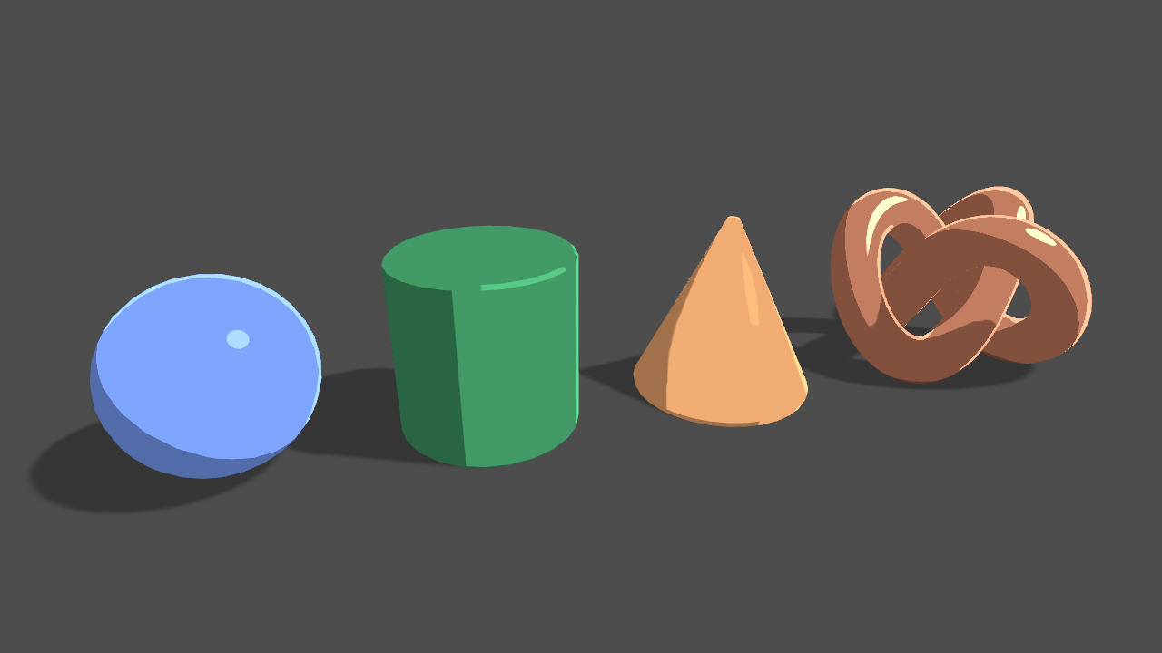
Learn to write a toon shader for Unity engine with specular reflections, rim lighting and shadow casting.
Hey so I have a compute shader, where I need 8 things to add to one thing, and then add that one thing to a new list
Thing is, I only want that one thing added to the new global list once instead of 8 times, how could I go about doing this?
Can a compute shader share the same texture and account for changes between kernel functions?
well, I haven't loaded it into Unity, but pos should be a float3 not a float. The macros may require specific variable names... You're using pos and also vertex at the same time. Maybe you need to, IDK, I'd have to dig in more.
Reposting in the proper channel. Does anyone know why my procedural blender granite material looks like this in Unity?

Because Unity isn't blender?
You need to recreate shaders in Unity.
Oh. I looked it up and it seemed like you could import those materials, sorry
apparently what im trying is very old way of doing it which seems to be out of date
Well, materials kind of import, but shaders won't. And IDK how a PROCEDURAL material works in blender, but probably has a shader part.
Alright, thank you
You're not that far off, trace down the macros and variable names. But pos is a float3 in 3D. And it might be used instead of your v.vertex (SV_POSITION semantic).
And yeah, check newer versions.
it actually seems like its float4, it says cant convert float3 to float4 if i use float3
OK, float4, mb.
This says you need a variable named pos, not position or vertex:
https://catlikecoding.com/unity/tutorials/rendering/part-7/
So you'd want your pos to be your SV_POSITION variable.
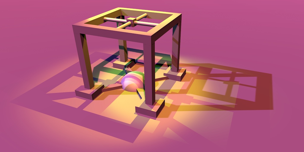
A Unity Rendering tutorial about supporting shadows. Part 7 of 20.
He deliberately goes through syntax errors and names, and fixes them in that tut.
And yeah, brain cramp on the float3 vs float4, sorry.
I think .w is the perspective divide....
it looks like it has to be its own pass maybe
I'm having a new issue where my material is pink but I'm not sure why. I tried looking it up but the results didn't help me.

there we go, i found some more updated documentation for it and that was all i needed to get it right

Shadow casting? Yes, it is its own pass. Shadow receiving is built into the main pass IIRC, or it is spatted on afterwards. May vary in forward vs deferred.
Try walking through that catlike coding tut, might help ya. 🙂
Hello, would anyone know why a shader in vr its good on the left eye but on the right eye its not where its supposed to be?
you need to enable rendering on both eyes on the shader, i dont recall what its called rn but give me a moment and ill find it
Thanks, tho its getting rendered on both eyes its just not where it supposed to be on the right eye
do you already have
UNITY_VERTEX_INPUT_INSTANCE_ID inside appdata, UNITY_VERTEX_OUTPUT_STEREO inside v2f and UNITY_SETUP_INSTANCE_ID(v); UNITY_INITIALIZE_VERTEX_OUTPUT_STEREO(o); inside the vert function?
if so then i imagine its something with vertex displacement that isnt matching with both renders
stereoscopic rendering. And there's two types...
Single pass MRT (multiple render targets) where it computes each eye in the same pass and writes to two output buffers, then there's the pass-it-twice method when MRT isn't supported.
ima give it a try with this, I thought there was maybe a uv problem so I used ComputeGrabScreenPos to do it but that failed to
cool beans
hmm didn't really work I tryed multiple stuff

Can a compute shader keep track of RWTexture3D data between kernel functions?
And if so why do I have to set it for each kernel versus just the shader
whereas I can set it per shader with things like ints and floats
It probably has something to do with resource binding and/or how the engine deals with such. But it can retain data.
It can even retain data between frames.
I'm having a lot of trouble with my chunk rendering code, I'm trying to make terraforming for the chunks but it seems to only apply in "arbitrary" cases such as when the full mesh hasn't finished generating or the chunk is far away enough from the player.
If I try to apply the terraforms as the chunk is generating for the first time it works but if I try 5 seconds after it won't.
I think I figured it out for anybody having a similar issue. Make sure you UPDATE your RWTextures using the ComputeShader.SetTexture() every time you dispatch the compute shader, for some reason this seemed to be the only way to account for changes to the texture.
you are probably using a different render pipeline to what the shader supports
try a different shader
also, you can't import shaders from blender, but you should absolutely not use procedural materials in Unity or any game engine, try baking the texture you get from the material in blender
hey did someone tell me where is the "alpha" section on the Fragement shader ? i see a tutorial and the guy link his shader to an alpha at the end and i have nothing like that ?
or maybe it is call something else
It shows up only if you enable alpha clipping or make the shader type transparent in graph settings in the modern UI
i see, where is the graph setting ?
Can you find the graph settings tab?
this ?

is there a way to cut out / remove areas of a texture after you sample it in shader graph?

i can make the black transparent but that leaves the texture as big as the original
You can also move and resize textures using Tiling And Offset
But usually it's better to add the cropping and transparency in an image editor so it doesn't have to be done at runtime
yh but i'm generating the image in shadergraph.. so i guess i would need to use 2 shaders, one to generate the image and then another that can get that image and tile / offset the result of the first?

guys I just import some assets
and due to the memory loads
I plan to remove supporting component for the shaders
I might only need the Albedo
now I remove all the supporting textures for a single shaders
but is there any chance to do such thing at a batch ?
since I have a lot of material on the scene (can I not do this one by one) ?
You can multi-edit all materials that use the same shader
yeah but each object using different shaders : )
Your next option is probably making an editor script that can loop through materials and set properties by reference, if there's a matching reference
Sounds like a lot of shaders to have 🤔
or stupid method, what if just delete all unncessary texture from the explorer ?
Sure, worth a try
im working on this toon shader and i want to use antialiasing between the shades. i as you can se i have some on the specular and highlight. but i dont have it on the shading. this is the code im using.
float3 N = normalize(i.worldNormal);
float3 V = normalize(_WorldSpaceCameraPos - i.wPos );
float3 H = normalize(_WorldSpaceLightPos0.xyz + V);

// Toon Blinn-Phong
float shadow = SHADOW_ATTENUATION(i);
float NdotL = max(0.0, dot(normalize(i.worldNormal), normalize(_WorldSpaceLightPos0.xyz)));
float4 light = floor((NdotL * shadow)/_Detail) * _LightColor0;

float4 BlinnToon = (light + _AmbientColor) *_LightIntensity + _Brightness;
also extra question. idk if this is lambert, Blinn or Blinn-Phong lighting. i got a little unsure as i saw two things saying different things

it would also be great if i could increase the antialiasing between the outline and the rest of the model. which is made by rendering it again behind but bigger
Can someone Give me a link to the overview of how to make functioning materials (ie bump maps, emission maps, normal maps, ect)?

what unity version and render pipeline are you using?
Hey does anyone know how to change the standard rp shader to an spr shader graph? I have a shader that only works in the standard rp but in Hdrp is pink and I cant have it be just a lit shader because it is a shader for an ocean
@ me if you need my shader scripts or you can help
is it surface shader or vertex/fragment shader?
btw, automatic conversion doesn't exist, you have to recreate the shader in shader graph yourself (you can use custom function node to put some of the shader code there)
seeing the shader code could help
its a Fast Fourier transform ocean shader and i hav no idea how I would be able to recreate it in shader graph
that sounds like loops and stuff (shader graph doesn't support loops). most likely most of the shader code can be put in custom function node
huh... that's quite complicated
@grand jolt how much experience do you have with (surface) shaders?
fun fact, unity is currently working on hdrp/urp surface shaders so in future that shader would work straight away or with very small changes in hdrp too
Not a lot, I have very basic knowledge of shaders this ocean shader was not made by me
ok so first you could create all of these properties with their initial values and stuff

Hey! I've made a shadergraph for a portal, the game it's in is a hand animated one with a relatively low framerate. Is there any way to reduce the update ferquency of the shader time to something like 1/10th of a second?

no, it's not possible. everything is rendered once every frame, you can't render certain objects only once in a while
Ah, you mean update the shader time value with script?
but they don't talk about effect. that won't make performance any better
It is purely aesthetic reasons
all you have to do in the shader, is where you pass time in, multiply the time by 10, round it up, then divide it by 10
ah, then I misundestood. I thought you meant you want to save some computations because you talked about framerate and stuff
and then use that value you get for the time
you can do that in the shader too
Ah clever
I guess both shader and script would work, whichever is easier for you to implement
Shader seems more streamlined
yea.. script on the other hand would be better on the performance, but at this scale I doubt it would be a problem
Ah, didn't know that actually
I just assumed that it had an overhead
there are lot of learning resources pinned on this channel
Thank you
most likely the overhead of doing that is very negligible compared to the rest of the shader but of course it still requires some extra calculations for each rendered pixel (doing that in C# script on the other hand would make it so the value needs to be calculated only once per frame and not for every pixel separately)
If performance becomes a problem, you should keep any pre-computation on the cpu if you can, and try to reduce the amount of operations you do on the gpu. It's also worth to look at which type of operations need a lot of execution time. For example "pow" is really expensive, but sometimes you have to use it
I wouldn't say "really expensive". some even use procedural patterns like Simple Noise Node which uses something like 6 pows and 12 sines 😅. I'm really surprised if Simple Noise Node can be good choise for mobile platforms for example (on vertex stage that's not that bad tho assuming vertex count is relatively low)
I guess for small effects, like magic projectiles it would be fine (even tho most people probably use it for something stupid like water 😵💫 )
But yea, it's not that hard to get a seamless repeating noise texture
Everything you possibly want to know about starting to learn how to do stuff is in here. https://docs.unity3d.com/Manual/SL-VertexFragmentShaderExamples.html
If you want something more entertaining to work on than just this i would recommend trying this video series on YouTube:
https://youtu.be/kfM-yu0iQBk

Welcome to my three part lecture on shader coding for game devs 💖 I hope you'll find this useful in your game dev journey!
If you are enjoying this series, please consider supporting me on Patreon!
🧡 https://www.patreon.com/acegikmo
00:00:00 - What are shaders?
00:03:00 - Case study/screenshots from FFXIV, Overwatch & more
00:37:42 - The Struc...
Freya holmer is great to get started but doesn't explain everything like in that unity documentation
And then they use multiple of them to get nice looking water 😯. There’s free seamless noise texture generators online so I don’t really see a reason to use those nodes (apart from vertex stage shaders)
I think there are ways to sample textures in the vertex stage
Is there a reason not to?
Ah, see that my preconceptions about performance were totally wrong. Thought textures took long and noise was fast 😅
Why should it be particularly bad to use it for water?
Water is usually rendered on the whole screen = more noise pixels to render
Also, just simplex noise for water isn't even that realistic
Sampling texture just takes values from a table of colors (its similiar to getting value from color array). Noise functions needs to calculate the colors runtime
Only SampleTextureLOD works on vertex stage. There’s no problem sampling texture on vertex stage but I just meant using procedural noise functions in vertex stage is usually pretty fine in terms of performance because vertex count is usually relatively low compared to fragment count.
Right!
Yeah makes sense that price is shadercomplexity X pixels
Gpus are weird sometimes but that’s roughly how it works. On vertex stage the overhead is complexity X amount of vertices on the mesh
Generally, you're correct. A texture read is "more expensive" overall than some math (YMMV on the math part, depends on how complicated). But GPU is built to read textures and apply them, so samplers are allocated, texture reads are started, other stuff is done if possible (the optimizer will even move the texture reads up as high as it can in the processing order) and then there's latency hiding that allocates many of these processes and stacks them, and waits for memory to be read/sampled from the texture memory, and then comes back later when the data is ready.
So with all that going on, we're back to "how fast is fast enough?"
Yeah, I try not to worry about performance before I need to, but it's still healthy to be aware of good practices
Does anyone use any plugins for unity shader files?
b/c intellisense doesnt work on .shader file
what do you guys use. please tell me.
Is there a way to send a structuredbuffer with an array in it to a GPU to a compute shader
there is only one. the HLSL tool plugin (not reply to pjbomb2)
Is there a way to render a mesh renderer in the UGUI.Rendering.RenderOverlays render phase or to set up a camera to render after that? I want to render a 3d mesh atop a canvas without using another render texture and can't switch the canvas to Screen Space - Camera because the camera is in a different scene from the canvas. I'm sorry if this is the wrong channel, there didn't seem to be a more obvious location for general rendering questions
"with an array in it"? Vague but OK. You can either
- send in a fixed-length array as part of the buffer's structure
- use a two-buffer approach, and put a starting index + length into your first buffer's structure and then add all the various # of array elements to the 2nd buffer.
IIRC the array has to be of a blittable type. See https://docs.microsoft.com/en-us/dotnet/framework/interop/blittable-and-non-blittable-types
Learn about blittable and non-blittable types. Blittable data types are commonly represented in managed and unmanaged memory and don't need special handling.
Does anybody know why I might be getting these artifacts in my screen distortion shader? I'm really not sure why these are here.
{
    Properties
    {
        _MainTex ("Texture", 2D) = "white" {}
        _Amplitude ("Amplitude", Range(0, 1)) = .5
        _Frequency ("Frequency", Range(0, 100)) = .5
        _Speed ("Speed", Range(0, 100)) = 1
    }
    SubShader
    {
        // No culling or depth
        Cull Off ZWrite Off ZTest Always

        Pass
        {
            CGPROGRAM
            #pragma vertex vert_img
            #pragma fragment frag

            #include "UnityCG.cginc"

            sampler2D _MainTex;
            float _Amplitude;
            float _Frequency;
            float _Speed;

            fixed4 frag (v2f_img i) : SV_Target
            {
                int speed = round(_Speed);

                float xOffset = cos(i.uv.x * _Time[speed] * _Frequency) * _Amplitude;
                float yOffset = sin(i.uv.x * _Time[speed] * _Frequency) * _Amplitude;

                i.uv.x += xOffset;
                i.uv.y += yOffset;

                fixed4 c = tex2D(_MainTex, i.uv);
                return c;
            }
            ENDCG
        }
    }
}

Not native speaker. Reading about graphics and often meeting word "fidelity". What does it mean in graphics context? Example: "If the GPU on the device running your Project does not support the rendering path that you have selected, Unity automatically uses a lower fidelity rendering path. For example, on a GPU that does not handle Deferred Shading, Unity uses Forward Rendering."
Hi guys, Iim tryting to figure out how to flip a result in the shader graph, does anyone know perhaps? I've tried the flip node but it turns the whole thing black, I also tried rotate to see if this could help but it just changes the colors and doesn't do anything else... I've tried to look it up on the internet but most people script their shaders 😅

did you mean one minus node ? you want to turn white values into black and black into white ? if so, then one minus is the node you are looking for.
No I meant like having it flipped, the white part should be mirrored if you want. I'm trying to create a seamless noise that I can animate for an effect i'm working on.
IDK, but "_Time[speed]" looks suspicious to me. _Time is a float4 and you've got the _Speed property ranging from 0 to 100. Still, whatever it is returning should be in the 0 to 1 range due to sin and cos. Did you want to scale _Time like "_Time.y * speed"?
Maybe check sampler state settings too.


https://www.youtube.com/watch?v=a5PbtUoHyQo&list=PLgCzUN8NgXu2Gb23_wiHyBWesCRL3PkXg&index=45&t=450s&ab_channel=WuzzyWizard
i follow this to 7:30

Hope u like this tutorial and that is was helpful.
➤ Discord: https://discord.gg/x7K92pJ
➤ Twitter: https://twitter.com/wuzzywizard
➤ Twitch: https://www.twitch.tv/wuzzywizard
➤ Patreon: https://www.patreon.com/wuzzywizard
why my shader become a line like that?
@hushed basin make sure your texture is set to repeat, not clamp in import settings
dam, that is the trouble, thank you so much ❤️
Try Tiling and Offset node with a tiling of -1
anyone can help me; i'm trying to do a gradient on 3d object from the base to the top any idea?
I think it's pretty similiar to "accuracy" or "quality". In terms of rendering path fidelity goes Deferred > Forward > Vertex Lit. With rendering paths the fidelity means how big portion of lights are calculated per pixel and does the rendering path support realtime shadows etc. Instead of calculating lights for every pixel lights can be calculated on vertex shader and then interpolated to fragment stage (Vertex Lit uses only per vertex lights)
Thanks
np. do you need more information about the rendering paths in general or did you only want to know what "fidelity" means?
I'm trying to figure out how graphics work in unity and how to use command buffers. So yeah I need more info. I don't understand what you mean by how many of lights are calculated per pixel tho