#archived-shaders
1 messages · Page 234 of 1
Here is the code used for the shader : https://pastebin.com/3tzF2sRf
Two questions :
- Why is the texture blurry? :0
- Why is an offset applied ?
Here is the material used on the left object

here is the one on the right

Here is the texture

@hazy sage
- I'm still looking but :
- this shader is using world space coordinates to apply the textures, not the UVs of the object, and that could easilly explain the offset
Hum, no, for the blurr issue I definitively don't get it
Hello, just wanted to start learning something about shaders and for no reason theese things happen all the time, at least in lit and unlit shader graphs, those were the only I tried yet. What could cause the problem?


Ah, so I figured it out, it was the same thing in my case
Ah, thanks anyways
Can someone suggest an HDRP shader to use that mimics even a little of what this shader did: https://youtu.be/cRfUefUUGIg

Proof of Achievements no other gamer has: #1 world ladder Starcraft #1 World ladder Broodwar, #1 World ladder Warcraft3 at 200-0, first to 1500 wins Warcraft3, #1 World Diablo2 Hardcore experience ladder, #1 score Pittsburgh without Turtle Tip 1989 Nintendo World Championships, #1 world C&C3, #1 World SC2v2/l https://www.crystalfighter.com/achie...
It looks like an unlit transparent shader with emission + a bloom post process
What exactly is a Surface Shader in comparison to a vertex/frag shader?
Like what IS alpha clipping?
it's not supposed to blend, it's just cutoff point for the mask
if you need to blend things, you have to use transparent shader instead of opaque one
@hidden lance
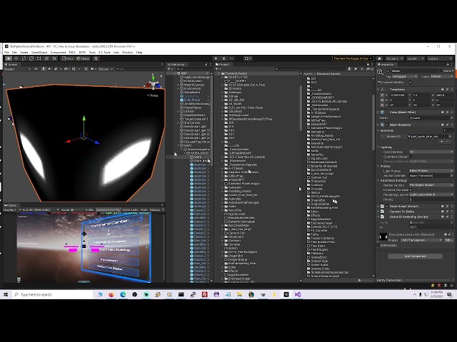
there are no shadows in play mode, left part is scene mode. I am using Toon Shader

nevermind, my camera was too far for shadows to be seen
trying to use a shader asset downloaded from asset store, it already has alpha and alpha clipping. Found someone's notes online about adding blend channel but couldn't use it


When exactly is the Surf function called in Surface Shaders relative to the normal Vert/Frag methods?
@fervent tinsel
@hidden lanceif it's paid asset, you shouldn't post the source content here
also I'd go ask the asset publisher about that as it's their asset 🙂
A surface shader is a simplified way to create lit shaders for the built-in render pipeline. The idea is you specify the input data you need and return PBR outputs in your surf function like Albedo, Emission, Smoothness, etc... The surface shader is converted into a regular vert/frag shader that calculates the inputs you need and combines your outputs.
When exactly is this surf function called in the normal Vertex -> Generate Interpolators -> Frag pipeline?
Or is that not how I should be thinking about it?
The surf function is called in the generated fragment shader, after all the requested inputs have been calculated, some calculated in the generated vertex shader, some in the fragment shader.
I've noticed that there are ways to define your own Vertex/Frag modifier methods in Surface shaders. So is the order of operations like...
Vertex
- VertexMod
Generate Interpolators
Frag
- Surf
- FinalColor
If you're interested, you can view the generated vert/frag shader from a surface shader by selecting it and pressing this button

That will reveal all of its secrets
It would be nice to have some recent perspectives on this, as most discussion is many years old by now
Though the answer seems to be "potentially yes, on old harware especially, but test it"
It seems to be a very complex question because compilers can optimize some if statements but not others, and some GPUs are decent at calculating them while others are not
I think it also depends how frequently the outcome changes (like how large chunks on the screen are having same condition). The way I understand it if like every second pixel have different condition, all different cases are calculated and useless values are just disposed. I think that was the case on older gpus atleast
@grizzled bolt@dim yoke
https://medium.com/@jasonbooth_86226/branching-on-a-gpu-18bfc83694f2

Medium
If you consult the internet about writing a branch of a GPU, you might think they open the gates of hell and let demons in. They will say…
so I have a worldToLocalMatrix.inverse being sent to a compute shader transform a ray position
How do I use the inverse of this matrix in the compute shader without sending it in? Cant I like reorder the mul in shader? or how...
I need the inverse of the scale in the matrix
used the old way instead, created 3D models of text/type and used this shader. Problem temp solved
also does anyone know a way for me to get access to any of the shader model 6 features in unity?
This is what I got, the walls are black and not transparent, dots aren't blue: https://youtu.be/ViHh0PDhJII
Proof of Achievements no other gamer has: #1 world ladder Starcraft #1 World ladder Broodwar, #1 World ladder Warcraft3 at 200-0, first to 1500 wins Warcraft3, #1 World Diablo2 Hardcore experience ladder, #1 score Pittsburgh without Turtle Tip 1989 Nintendo World Championships, #1 world C&C3, #1 World SC2v2/l https://www.crystalfighter.com/achie...
anyone have tips on making a gradient? im trying to make it so that i can change the direction of it so it could be top to bottom or left to right nice and seamlessly. cant really find anything that works right
no im using the built in pipeline since its support shader graph on unity 2021
Not this one. HDRP/Unlit shader, set to transparent, with emission color
I have many shaders like this. If you fix it up and I make a bazillion dollernos, find me and I'll pay you off. https://youtu.be/sfpkzZGKIn0

Proof of Achievements no other gamer has: #1 world ladder Starcraft #1 World ladder Broodwar, #1 World ladder Warcraft3 at 200-0, first to 1500 wins Warcraft3, #1 World Diablo2 Hardcore experience ladder, #1 score Pittsburgh without Turtle Tip 1989 Nintendo World Championships, #1 world C&C3, #1 World SC2v2/l https://www.crystalfighter.com/achie...
Also take time to read the doc on how to use the HDRP provided shaders.
In you case to have a somewhat similar look to what I saw in the first video I can see two solutions :
- Assign the texture to the surface color + set the color value to the desired tint. Optionally change blend mode to additive
- Aslo assign the texture to the surface color (I do hope that this texture has transparency information) but set the color to black. Now you should have the shape but full black. Add emission to the material. I recommand to check the "use emission intensity" toggle, set the color to your need, and tweak the exposure weight to have the glow effect (provided you have bloom in your scene)
The other last option is to make a custom tailored shader to your need using shadergraph
how do i get the number of elements in a structuredBuffer in hlsl ?
im trying to loop thru it in a custom function in shaderGraph but i cant seem to find a way to get the number of elements
Possible to loop until no data found or something?
On a meager Google search my self I see there's no .length so you go me wondering now. I'm assuming the array you're looping thru isn't a set length
idk , this is my first time using compute buffers , when creating one a set amount of memory is explicitly allocated so im guessing it's treated as a whole chunk of data ?
Hmm, & is there a way to do a if (data == null/garbage) stap
I'm not sure though obviously, sorry 😉
i have no idea , and seeing how i couldnt find anyone talking abt this , im probably asking the wrong questions
Ha, yeah. Sounds like you need to know loop size ahead of time 🤷
i meaaaan , you have to set the item count the buffer can hold when creating it so maybe i have to overwrite the whole thing idk
Haven't used it before but StructuredBuffer.GetDimensions may be what you want, returns numStructs and stride https://docs.microsoft.com/en-us/windows/win32/direct3dhlsl/sm5-object-structuredbuffer-getdimensions
Typically looping through something when you know the length can be better though, as the compiler can unroll the loop
thanks ! that seems to be it , i passed by GetDimensions but i didnt think it would be a void with out params
That's the size, but MAY not be the number of elements you've actually filled, unless filled-size = buffer size.
It's easiest to just pass in an "actual count". Then you can over-allocate the buffer and fill, say, 78 out of 100 elements. Or whatever. You won't need to re-allocate it all the time if the size changes, as long as you have enough room in the buffer for the current data set.
but the microsoft docs specify that numStructs is "The number of structures in the resource." that doesnt strike me as capacity
ugh if only we could print out stuff on the console
I think it's the total allocated size.
However, there is a "hidden counter" and methods to increment and decrement it, but it has to have the buffer created in such a way as to support it. IDK off the top of my head if Unity specifies the D3D11_BUFFER_UAV_FLAG_C0UNTER flag for a regular RWStructuredBuffer. I just pass in the size if it's something coming from C#.
Also note here (this is interesting): https://docs.unity3d.com/Manual/class-ComputeShader.html
Metal also does not support GetDimensions queries on buffers. Pass the buffer size info as constant to the shader if needed.
Of course, that's a reference to allocated SIZE, still not necessarily your used-item-count, depending on how you implement it all.

So you'd at least pass the total size, or maybe the used-count if smaller than that, but you want to be able to do some range checking so you don't read/write out of bounds.
@maiden quarry
well this sure looks like something to research for the next few hours and possibly days
@meager pelican thanks for your input ! i really appreciate it
im editing my compute shader code in vscode, and each time i run it after editing, it breaks or behaves weirdly
but if i relaunch the unity editor, it suddenly fixes its act
has this happened to anyone or does anyone have some idea why this might be happening?
im talking about like, going into vscode, changing a line, saving, changing it back to the way it was when it worked, saving again, and suddenly its broken
Remy! You did it, you mad genius! You helped someone far more mad! Now I'm less upset, so maybe you're more mad now. But you won't be mad when I make a bazillion dollars and you find me & ask me for green backs! I had to: Surface type: Transparent/Additive was necessary not optional/color and emission had to use that texture/emission https://youtu.be/zWdU7cXQFXY

Remy: Also take time to read the doc on how to use the HDRP provided shaders.
In you case to have a somewhat similar look to what I saw in the first video I can see two solutions :
- Assign the texture to the surface color + set the color value to the desired tint. Optionally change blend mode to additive
- Aslo assign the texture to the surfac...
How would you create a shader that blurs everything behind it?
Doesnt a blur require you to know the surrounding pixels?
The examples I see lerp Scene Color with itself multiple times, each with an offset
Other type is using a downscaled rendertarget texture for a very cheap type of blur
I suppose you could combine them for a good compromise if rendertargets are an option
https://answers.unity.com/questions/319137/convolution-shader-for-blur.html there are some that implement an actual convolution matrix but I'm not smart enough to understand this stuff yet
how can i use AsyncGPUReadback?
do i need to add some "using" directive?
nevermind, i got it - it's just that vscode tooling im using doesnt support that functionality, i think
It's in UnityEngine.Rendering
When i paste my shader visual studio does the tabs all wrong.
aye, just vscode acting up, thanks
before paste

after paste

i have the same number of brackets of both types
it tabs after propertys for some reason
fixed it
the bracket at the end of the line was messing it up
it was supposed to be on its own line
I'm making a shader(gerstner waves) and when I apply the material to the plane the entire mesh including the vertices vanishes.
if you have any ideas feel free to dm or ping me i would really apprecieate it.

Testing the plane at (0,0,0) might give some clues. Make sure you are outputting the vertex positions in the correct space. (Object space for the Shader Graph port)
also try rotating all around it
how it there woooaat

yeah you must be geenrating points in world space instead of local
i.e. you're not incorporating the object's position/transformation in your shader
Can use the Transform node to convert from World to Object, before connecting to the Position port

It's difficult to tell the setup but try using the output of the Transform node in the Position output


I got it to work somehow, I used probuilder and it suddenly showed up..
quick question, how do i get shadows to show

@round linden I know this is extremely late, but you may want to try triangulating all of your faces in Blender and making sure that in Blender you recalculate your normals. You can find tutorials for how to do this, and neglecting to do either of these things can give the result you presented.
ping me if you have questions about that
Is get instance id slightly random? i tryed coloring all my hexagon objects that have x<-30 but it colored them quite randomly

im farly shore its happening in my shader
thats my shader
- FYI you can just say "OUT2 = OUT;" but it's a waste since you can build that into the expression below.
- You're setting color based on a texture read multiplied by a lerp from white to the instanced color from the array, based on the green channel's T, not checking any "x" value so IDK what you're asking.
- You don't need the alpha value in the fixed4(1,1,1,1)...you should just need fixed3(1,1,1) since you're using .rgb.
- fixed type has a limited range. So a value of 30 if you're checking that (IDK what you're saying in that regard)...is outside that range. It ranges from -2 to 2 with 1/256th decimal precision. https://docs.unity3d.com/Manual/SL-DataTypesAndPrecision.html
ah sorry for not being more clear
this shader is a color tint shader for draw instanced and it tints an amount equal to the green value of the texture onto a grey value equal to the red value. but thats not really important. the x i was talking about is the x position of the hexagons, and when there below -30x they are supposed to be tinted red but for some reason its quite random and im wondering if thats somthing to do with the instance id
OK, with instancing, unity groups up a bunch of objects, allocates a CBUFFER for instanced data, and passes you an instance ID for each instance. IDK if there is any order to the grouping of the object instances, nor do I think you should be able to count on any order since they could change the way the engine groups them at any time.
But I don't see the line where you're checking the x value of the position, but maybe you do that on the C# side.
None that I know of. Although the type of object queue may play a role (like drawing opaque queue things front to back), IDK that you can count on that at all. At least, not that I know of.
There's no way for them to predict the order that everyone would want, that I can fathom.
I mean, you want one thing, next guy wants another.
yea
They draw them in a way that makes sense to them, in groups that have data that can fit, by material or by shader or whatever.
On any invocation, your shader doesn't know what order things are drawn in, since it is all parallel anyway. So it's more like 64 of them are all being drawn at once.
ok
so i cant tell my shader to draw a sertain one of the instances with a sertain color using a material property block
Sure you can, sort of.
But maybe not with the MPB. Maybe by checking the instance ID directly.
Why do you want certain instance ID's a given color?
What you said you wanted was certain x locations a different color.
But the MPB colors map to the instances.
So if you have 3 objects...
The first one is red, the next is blue, and the 3rd is green in their MPB's.
It doesn't matter what order unity groups them in, the mpb color will match for the instance index.
When you get the instanced data.
You need to be using UNITY_TRANSFER_INSTANCE_ID(v, o);
And UNITY_ACCESS_INSTANCED_PROP(color)
I think they're called.
Just a Second.
Have you seen this? https://docs.unity3d.com/2021.2/Documentation/Manual/gpu-instancing-shader.html
That will show you how to get the color out of the MPB for each instanced object.
How you set that color on the C# side...based on x position or whatever you want...is up to you.
🙂
I have more of a 'technical artist' question but this feels like the best place for it.
I am looking in to how to make plants look like they are growing over time (start as a seedling and grow into a full tree or flower, etc.) but haven't come up with much.
My current method is to have multiple meshes that I swap between for each 'stage' of growth, but looking for something more gradual.
There is blend shapes, but those are really a massive pain to create and heavier on the performance. There is of course generating the mesh at runtime, but again, very heavy.
So I was wondering if there was perhaps a good way to do this using shaders? Truth be told I am not sure what I am thinking of, but thought I may as well ask in case someone had any ideas or things to look in to.
I've seen it done a couple ways.
Let me try and find something. They vertex distort, kind of extruding

Did you know that you can grow anything with Unity Shader Graph? Like an animation. A shader that can procedurally grow geometry. It's a very practical effect, used to grow vines for example. Or other 3d objects.
Enjoy!
00:00 Intro
01:04 Grow Vines Shader
05:45 Creating Vines in Blender
09:24 Shader Adjustments
10:24 Grow Vines Script
15:39 E...
thanks!!!
Besides that above, any form of vertex lerp (and probably UV, and perhaps surface normal) lerping would be good. Kind of tweening.
But you'd have to stuff additional data into the mesh somehow, like with vertex colors and/or UV's.
And you'd probably still want to swap a few versions in at various points to massively change things from one endpoint to another start-point.
You might even create the mesh procedurally by lerping between two mesh stages.
Thanks, the method used in the video seems like it would be to simple for my use.
Would be interesting to see the performance of generating the mesh procedurally via lerping vs something like blend groups.
ello, how would I change the Shader of an object in code?
say I clone a brick that has the standard shader.
then I want to apply a different shader to that brick clone, but not change the shader on the other brick
is that doable?
Change the material of the clone?
Generally you don't change the shader at runtime, you simply change the material
it's just that theres a bunch of materials as well as weapons with different materials so..
I really have to make 2 materials for absolutely everything? what I'm trynna do is make a clone of the player and have it always on top of any other 3d objects in the view
so if say theres a tree in the view you'd still see the player overtop
I'm trying to make a material from a shader and it should be a black to white gradient but instead its all grey anyone know why? also doesnt give me any of the normal options

shader editor

^fixed this
uint hash(uint state) { state ^= 2747636419u; state *= 2654435769u; state ^= state >> 16; state *= 2654435769u; state ^= state >> 16; state *= 2654435769u; return state; }
I guess this is a warning/question, but this random num generator I found explodes my computer when I put it in a loop and pass the counter to it. counting from 0 - 1920*1080
anyone have this happen to them/know why>
why is the alpha of my graph not doing anything
don't tell me you are calculating this on the processor
computation takes time
also, this isn't a shaders question then
maybe your graph is set to Opaque instead of Transparent?
for some reason my shader is doubling the distances and i dont know why

Maybe the logic on the shader is just broken? I don't think anyone would be able to help without seeing the shader/shader graph
Hi

i moved a shader graph asset to other project and it looked pink
i want to understand how to just move the asset from project to other without having this problem
No lol
yeah, its kind of hard to explain, as i'd have to get into the code a bit... hm
ill try to go by snippets
so basically im dispatching my shaders after setting the "origin" point of each chunk, marked in green here

as a float3 variable
and then the compute shader, with a dispatch group size of 8x8x8, calculates each "cube"
vertex points set as such
        {chunkOrigin.x + (tid.x)     * distanceBetweenPoints, chunkOrigin.y + (tid.y)     * distanceBetweenPoints, chunkOrigin.z + (tid.z)     * distanceBetweenPoints},
        {chunkOrigin.x + (tid.x + 1) * distanceBetweenPoints, chunkOrigin.y + (tid.y)     * distanceBetweenPoints, chunkOrigin.z + (tid.z)     * distanceBetweenPoints},
        {chunkOrigin.x + (tid.x + 1) * distanceBetweenPoints, chunkOrigin.y + (tid.y)     * distanceBetweenPoints, chunkOrigin.z + (tid.z + 1) * distanceBetweenPoints},
        {chunkOrigin.x + (tid.x)     * distanceBetweenPoints, chunkOrigin.y + (tid.y)     * distanceBetweenPoints, chunkOrigin.z + (tid.z + 1) * distanceBetweenPoints},
        {chunkOrigin.x + (tid.x)     * distanceBetweenPoints, chunkOrigin.y + (tid.y + 1) * distanceBetweenPoints, chunkOrigin.z + (tid.z)     * distanceBetweenPoints},
        {chunkOrigin.x + (tid.x + 1) * distanceBetweenPoints, chunkOrigin.y + (tid.y + 1) * distanceBetweenPoints, chunkOrigin.z + (tid.z)     * distanceBetweenPoints},
        {chunkOrigin.x + (tid.x + 1) * distanceBetweenPoints, chunkOrigin.y + (tid.y + 1) * distanceBetweenPoints, chunkOrigin.z + (tid.z + 1) * distanceBetweenPoints},
        {chunkOrigin.x + (tid.x)     * distanceBetweenPoints, chunkOrigin.y + (tid.y + 1) * distanceBetweenPoints, chunkOrigin.z + (tid.z + 1) * distanceBetweenPoints}
    };
i know that the "chunkOrigin" points are correct, because the gizmos draw them correctly
tid is the SV_GroupThreadID semantic
thankful for any insight but i dont expect much since the code is kinda trash
Does blenders shade smooth work on unity?
Whenever I set it to transparent it makes the entire particle transparent
yes. shading data is baked to normals of vertices. it should work same in unity and blender
Great thanks!
could this be about conversion of units?
theres floats, ints, uints...
does a uint converted to an int give the value of the uint, times 2?
cause that would make sense
this is so utterly confusing
I think it's just your math
something about how and what you're multiplying distanceBetweenPoints into
Can you prove that assertion? Just because the C# side gizmos are drawn correctly doesn't mean you're passing the data correctly for each "chunk" of 8x8x8 mini-boxes.
or...
Whatever you're using to actually draw this (like a DrawProcedural shader) is messing the origin locations up?
The offsets for each mini-box look good if I understand what you're doing, so it's the origins that are off.
if i wanna make a shader graph shader for UI, what graph do i create, what settings do i change?
The origin points are where the green sphere gizmos are on unity's side,
I tried two methods of passing them to the shader - via SetFloat for each x,y,z component separately and SetFloats, as 3 floats and a float3 respectively and both gave the same result, so i assume they should be passed correctly
Yeah, but in the code above, the 512 mini-blocks are relative to that origin point, and all the blocks are lined up correctly for each 512-block-cube. So the origin must be off somehow somewhere.
Either that, or you're messing with them in another stage somehow.
Okay - i got it. Ridiculously simple. I feel like an idiot.
I think..
Hold up
Yes.
The chunks themselves are spaced out, and there is no need to displace the mesh respective to the chunk origin point
The chunk itself is in the correct space, but it's mesh is displaced. So if i scoot them to the origin of the entire volume of chunks, then...

it acts properly

you were right, i was messing about too much
big thanks
🙂
however this is not the end of my troubles, haha
I have setup a custom editor for the entire volume of these chunks, and i use it to generate the meshes in edit mode.

If i were to now "reset chunks", which essentially just destroys the gameobjects, then recreate them, then the meshes, then

This happens!
And if i were to do it again, then every vertice of every mesh would generate at world space (0,0,0)
Could this be something in regard to how the threading behaves, or perhaps the buffers allocated to storing data to/from the shaders?
Would shaders be thing I'm looking for, if I want to adjust 2d sprites? I.e. if I wanted to slightly change the colours or randomly generate the stripes on something like this:

Thank you for the starting point. On a googling journey I go 😄
Bear in mind that if you wanted to make stripes like this it will all devolve to designing a good mathematical formula for it
Somewhat
Yeah thats the bit I'm worried about :p
Hello, what's the difference between Space Position(Default) and Space Position(Raw)?, i know one of them divide each Vector value by clip space W component, but what's that W clip space value?
is it like, a value that defines depth?
it's what performs the perspective manipulation
is it related to the frustum of the camera?
It normalises clip space into -1 -> 1 space (called normalised device coordinates)
The entire space is related to the frustum somewhat, so... yes?
If it's set to raw I think that the z is the actual depth, and once divided by w it's converted to NDC
My shader only appears in the scene window and not in the game window, am I not loading it somewhere I need to or something?


Go ask that in a Blender discord this is for unity only.
I've talked about this before but I just want to show how stupid it is in action. Notice the redirect node converts the float to a float4 for no reason! (This happens if you redirect after a multiply node)

pretty sure that's not intentional. you could report for a bug
oh I already told the team
How can I apply 6 textures for each face of a cube in a shader graph ?
Test the face normal value and use branches to select the proper texture to apply
But imho, it's easier to have a cube with one material per face
Or "build" a cube from quads :p
Or combine textures into a bigger texture atlas and UV map each face of the cube to the different parts of the texture
I can't put a texture in the "true / false" entries
I can't do that because I use worldspace to tile the texture xd
You can do it after sampling
Sampling? (Im very new to graphs xd)
The texture sample nodes 🙂
Hi, I have a relatively simple shader that gives the illusion of a container being filled with a liquid. The fill amount is set with a slider with a min and max setting to the level i want it to be able to be filled to. However these min , max values need changing every time I scale the container object differently, I am struggling to figure out a way to make the fill relative to the objects scale. I am very new to shaders.

And how do I do this? xd
Two samplers, one for each texture, and than branch by testing the normal value.
Sorry I mean how do I test the face normal?
Why do you need to subtract the object position ? If you use directly the value from the position node (without subtract) you will already have you levels scale with the object. Or maybe it's exactly what you don't want ?
I'm having trouble with my see trough shader. Can I tell my shader to only Z test on meshes that don't have the same shader? Or can I use layers to decide which material/meshes my shader can Z test against?
I've tried to adjust the render queue of my materials but it just switch the rendering order around even if use the same number.
For now I can only get the wanted result by batching my objects in a single mesh as you can see on the bottom right. Unfortunately this is not a valid solution for now.

Take the "normal" node. Plug into two node : abs & sign . And split both of them
From abs you have to do multiple comparisons like : X > Y & Y > Z.
This will allow to know the axis of the face.
Then, once you know the axis, check the corresponding sign to know if it's front or back on the axis. And select one of the 6 samplers for your textures
You're amazing, thanks for your time ^^
Basically, you're trying to do triplanar mapping with one texture per axis, right ?
Yes ^^ With one texture on each face
(so 6 different textures)
I didn't know the term "triplanar mapping"
May I shamelessly direct you to my node library (that I need to work on to again) : https://github.com/RemyUnity/sg-node-library
There are some nodes that will fit your need :


Wow, those nodes look exactly like what I need
I didn't test it out yet but is it normal that I can't assign default values there ?

Hum, I don't remember if you can assign default values to subgraphs. Maybe not.
But you can in the input field of the node itself
never mind I had to do it in the graph inspector x)
Also, is it what Im supposed to do ?

You're missing the "triplanar data build" node plugged in the triplanar data input (look at my first screenshot)
Oh okay thanks ^^
Itself need input for position and normal (from position and normal nodes obviously 🙂 )
What's the normal node I need to use ?
IIRC it's "input/geometry/normal"
It seems to be working! Only little problem is that all the textures are blurry

The top should look like that

Ah, yeah, because I could not do it in an other way and "retrieve" the sampler state of the textures, you have to provide you own sampler state in the last input of the node.
Create a sample state node, and you probably want to use wrap mode to repeat, and filter to point.


Are you using the same texture on the top&sides ?
Gonna be using this 👀
No that's why Im confused xd
(Also for later (or now if it's quick and easy to fix) how could I make it so the texture is applied on the green area and not the red one? (The red one is 1x1 so it works as intended, but what should I do if I want to apply it on the green area? (which is 3x4))

I'm confused myself, it should work 🤔

IDK why this is happening, iirc it should work properly :/
And for the green/red rectangle, you will need to scale the UV/position for this.
If you're sure for the scale, an easy way to go would be to divide the position input by vector3 (3, 4, 3)
but it will also strech top & bottom
Can I do it only for the sides?
It seems to be applying the side texture on top & twice on the sides

Yup it's mixing both

Oh @amber saffron could the fact that Im on URP change anything ?
Shouldn't.
Let me quickly fire up a project to check that
Thanks a lot for your help anyways :p
Found, raise the blend power (like, 1, anything else over 0 should work for a cube)
Wow! Thanks a lot :p
I don't want to bother you more but is there anyways you could help me with that too? xd
Yeas, trying to figure out an "easy" setup
So you can do this.
Each divide beeing the number of "tiles" where you want to spread your texture.
I've also set the initial size to 1

Looks like I'm missing some nodes to better controll the triplanar effect 🙂
Im gonna try that right away, you just solved a problem I had for 3 days x)
How did you get the matrix construction to only 3 entries though?
Hover a node and tick the top right arrow to hide the unconnected things 🙂
Oooh thanks
I works, I just don't know what to say it's perfect X)
Thanks a lot :p
Damn Im so grateful
I need the subtract otherwise the liquid will fill when it moves around the scene

Hum, I don't get it then. Since the logic is based on the position in object space, if you don't subtract this should not happen. Unless you're already transforming the fill levels from world to object space from some scripts ?
hmmm, no script yet
for example, here is with object scale 1 on all axis

this is with scale 5, all the same fill level

But like I said, if you remove the subtract, and be sure that the position node is using object space .... the fill level should be scale dependent.
ahhh true , however I was using world positioning so that the liquid was level to the world and not the object

Okay, this makes sense 🙂
I think you could try scaling you levels value with the object scale in your original setup ?
But in the best manner, this would require an additional vector value like "size" to have a notion of volume of the object (in the future there will be a "bounds" node for this) and also us this to controll the filling levels
mmm yea that waas my thought but struggled with implimenting
I'm a bit busy to try it out on my side, but something like taking a vector 3 holding the unscaled size of the object, transforming it from object to world space, and taking the absolute Y value of this should give you a scale factor to apply to your filling level.
Mmmm ill see if i can get that to work
I did get somewhat close earlier simply normalizing the values and remapping
like so

however, the way it filled changed, filling around a central point, but it was between 0 empty and 1 full , at all scales

but yea I will attempt making the fill factor the scale
            #include "UnityCG.cginc"
            #pragma multi_compile_instancing
            struct appdata
            {
                UNITY_VERTEX_INPUT_INSTANCE_ID
                uint vertID : SV_VertexID;
            };
            struct v2g
            {
                float4 vertex : SV_POSITION;
            };

            v2g vert (appdata v)
            {
                UNITY_SETUP_INSTANCE_ID(v);
                UNITY_GET_INSTANCE_ID(v);
                uint instID = unity_InstanceID;
                //uint instID = 1;
                uint vertID = v.vertID;

            }
any idea why unity_InstanceID would be undeclared identifier?
Hey, can I somehow increase the size of points on a mesh?
I have a mesh being created and I have a MeshTopology.Lines for the first material, then I have a submesh of MeshTopology.Points for the vertices. The points though don't all show and honestly I can't figure out where I should go from here, cause I could create a GameObject tied to every vertex but that's quite the performance cost for it I think


define PSize in your appdata struct
okay so if I have no idea what the appdata struct is, should I just take a default shader and like throw that in?
I have a custom shader I think actually maybe I could use that
it's a vertex color one though maybe bad idea
oh ooops, define it in your v2f struct
then set it to whatever
struct v2f
{
  float size : PSIZE
  ...
}

o.size = someSize
this is the custom shader I have (did not write), I'll go read a tutorial brb

okay so I followed a tutorial and I think I understand
I wrote this
Shader "Custom/VertexShader"
{
    Properties
    {
        // Properties of the shaders
        _Color("Vertex Color", Color) = (1,1,1,1)
        _Size("Vertex Size", Float) = 2
    }
        SubShader
    {
        // Code of the shaders
        Tags{
            "RenderType" = "Opaque"
            "Queue" = "Geometry"
        }
        Pass {

            CGPROGRAM
            #include "unityCG.cginc"

            #pragma vertex vert
            #pragma fragment frag
            fixed4 _Color;
            float _Size;

            struct appdata {
                float4 vertex: POSITION;
            };

            struct v2f {
                float size : PSIZE;
                float4 position: SV_POSITION;
            };

            v2f vert(appdata v) {
                v2f o;
                o.position = UnityObjectToClipPos(v.vertex);
                o.size = _Size;
                return o;
            }

            fixed4 frag(v2f i) : SV_TARGET{
                return _Color;
            }

            ENDCG
        }
    }
}
I put it on a cube and none of the vertices are doing anything

set the size of the vertices to 80 and still no change
it's definitely working on the vertices, like if I change the color it changes the color but
not changing the size
yes
the submesh is the points mesh

where the lines connect there's a vertex and each vertex is a point in the submesh
this is the first time I've heard of it
that might be a mistake?
i think the U should be capitalized
im doing something similar and psize works for me
that didn't seem to fix it either
my code is legit just this

the color works
so if I change the color in the inspector the vertices change color, but the size does not work

?

you fixed the culling/LOD issue I had that I was unaware was that, but it won't change the point size, maybe it's not pulling the right var in but it works with my _Color
if I manually define _Size to be say 10 is the normal size 1?
either way it's not seeming to work, but curious as to how it should
hm it's also showing these points through my solid mesh

if anyone has any solutions for this, I can't get my PSIZE attribute to matter on MeshTopology.Points and now my points are visible through solid mesh
they're visible because you set ztest to always and zwrite off lol
you keep saying all these words like I'm magically supposed to know what they mean if I'm new to shaders
It actually seems to be in order but when it goes over 512 (which is double the precision of a fixed variable) it goes back to 0, and also im using draw mesh instanced so i cant use instanced properties because i only get 1 material property block
does anyone know how to make instanceID into somthing bigger than a fixed variable, there's more info about my project in the reply link.(i can repost if needed)
What should ZTest be set to if I want it to just render normally? Like I don't want ZTest Less because it doesn't render all the points, or rather it does it horribly, but Always looks glitchy too when things render through
What is "existing geometry" anyways? Why is there not just a "don't draw if it's behind non-opaque geometry" feature
im fairly shore its this
uint instanceID: SV_InstanceID
but when i try changing the type it throws an error
hmm no it says that should be a number between 0 and 4294967295
i think i might have found it

I tried to use this custom function node

It worked in the video I was watching, but in my project it caused an error where Direction isn't "completely initialized"
I don’t know if that changes anything but i think you should have #endif at the end
It may be that compiler thinks that the if else chain doesn’t end there and therefore it may be that not always Direction is given a value
Oh right
I'm pretty sure I did use that
Just forgot to screenshot the video from that part
Could it be because I'm using SRP and not HD or URP?
I don’t know
nope gives me an error when i increase it
oh well ill just draw in groups of 512
Alright, here's the code I ended up using. Taken from another tutorial, but it still doesn't work


Anyone know why PSIZE wouldn't work to increase the size of vertices in a points mesh topology
This answer from bgolus might explain it, but probably not what you want to hear https://forum.unity.com/threads/how-to-set-point-size-of-vertex-in-shader.1012795/#post-6566788
As they mention, rendering a bunch of instanced meshes/quads (e.g. with Graphics.DrawMeshInstancedIndirect) might be something to look into as a replacement
hm, interesting
what do you mean, a bunch of instanced meshes?
currently it's lines + points as two separate meshes/materials
how do I know how "wide" a point is if I wanted to multi-layer the points submesh?
I could make a bajillion game objects but that seems slow
I think you should be using #ifdef SHADERGRAPH_PREVIEW not #if.
But the custom lighting code is intended for URP. If you're using the built-in RP (you mention SRP but that means scriptable not standard) it might still work though as GetMainLight does seem to be a part of the built-in shader graph files (e.g. https://github.com/Unity-Technologies/Graphics/blob/85680b4c3b49b1751d72db1a776368e056352aaf/com.unity.shadergraph/Editor/Generation/Targets/BuiltIn/ShaderLibrary/Lighting.hlsl#L129)
it was before when I went for a larger than 50x50 size grid
Sorry, I meant the "standard" (built-in) pipeline
But I see
Probably gonna use URP in the future anyway
If you use URP I've got some functions/subgraphs here which may help https://github.com/Cyanilux/URP_ShaderGraphCustomLighting
Not sure why that isn’t set as standard at this point, since that and HDRP are where all the new features are at
Ooh this looks nice
Thank you
I mean rather than rendering a point mesh, render a quad at every point - with a shader that makes it face the camera (can search for "shader billboard effect" to achieve that). Can put a circle shape/texture on those quads with clip() function to make it round.
I find this page has some good examples of rendering lots of instanced quads (specifically you'd probably want the DrawMeshInstancedIndirect example in this case). This way it doesn't need many gameobjects. https://toqoz.fyi/thousands-of-meshes.html
I guess a simpler solution would be to use a Particle System as that would handle the rendering side for you. In a C# script could loop through your point mesh and call ParticleSystem.Emit with the emitParams and override the position. https://docs.unity3d.com/ScriptReference/ParticleSystem.Emit.html
How can I make a shader where an area of the object is a different colour if it collides with another object?
i want visual feedback that an object is colliding into something
can i pass a dynamic list of vectors to a shader?
Dynamic in what way? Like changing during runtime? If so, you'd need a script to pass the vectors I think
i do but i'm finding like no docs on what data types shaders allow
e.g. Lists
ah nevermind, i'll just do another approach
can you debug log shaders?
i want to get the distance between 2 vectors
_ContactPoint("ContactPoint", Vector) = (0,0,0,0)
...
if (Vector3.Distance(IN.worldPos, _ContactPoint)
 < 1)
    c = _Color2;
else
    c = tex2D(_MainTex, IN.uv_MainTex) * _Color * 0.1f;
nvm, got it working
anyone know why CommandBuffer.DrawProcedural would work
but CommandBuffer.DrawProceduralIndirect does not?
i checked renderdoc and the latter literally never gets called
Hey i wanted to know if anyone could help me make a world space shader in to a uv object shader
Hey what is the best way to do a flowing scarf or similar ribbon like thing in a 2D pixel art game?
I have a feeling it might involved shaders, but maybe not
I'm not trying to pixelate 3d objects, unless that is the best way to do it in a 2d game
It sounds to me like you're trying to use instance ID as some kind of unique identifier for all instances of these objects in your game, but that's not really what it is.
It's an instance-ID for a Unity-Engine constructed BATCH that happens during GPU instanced draw calls. So you can end up drawing 3 batches of these objects, each batch would have instance ID 0 in it. You seem to be trying to get to a point where you have a unique ID per MESH.
That's a perpetual problem. IDK if it is Unity specific, or just how GPUs work, but meshes don't have much per-mesh level data. I wish mesh-info had one unique per-mesh user-defined variable (uint) per C# instance that we could assign at the C# engine level, and then use that as an index into a user-defined per-mesh buffer where needed.
Maybe----> You could use MPB's and have a property for that unique ID, so you'd assign that ID in there. So each object on the C# side would have an MPB, and that MPB property would hold a uint or float (int value) that was an index into some other buffer you create, unless you can just put all the data into the MPB to begin with.
But I'd let Unity do its GPU instancing as GPU instancing and not try to convert that into something that it is not.
Hey guys! Could you help me translating this code to shader graph? The code is used to apply a palette to the original sprite
varying vec2 vTextureCoord;

uniform sampler2D uDiffuse;
uniform sampler2D uPalette;
uniform bool uUsePal;

vec4 bilinearSample(vec2 uv, sampler2D indexT, sampler2D LUT) {
    vec2 TextInterval = 1.0 / uTextSize;

    float tlLUT = texture2D(indexT, uv ).x;
    float trLUT = texture2D(indexT, uv + vec2(TextInterval.x, 0.0)).x;
    float blLUT = texture2D(indexT, uv + vec2(0.0, TextInterval.y)).x;
    float brLUT = texture2D(indexT, uv + TextInterval).x;

    vec4 transparent = vec4( 0.5, 0.5, 0.5, 0.0);

    vec4 tl = tlLUT == 0.0 ? transparent : vec4( texture2D(LUT, vec2(tlLUT,1.0)).rgb, 1.0);
    vec4 tr = trLUT == 0.0 ? transparent : vec4( texture2D(LUT, vec2(trLUT,1.0)).rgb, 1.0);
    vec4 bl = blLUT == 0.0 ? transparent : vec4( texture2D(LUT, vec2(blLUT,1.0)).rgb, 1.0);
    vec4 br = brLUT == 0.0 ? transparent : vec4( texture2D(LUT, vec2(brLUT,1.0)).rgb, 1.0);

    vec2 f  = fract( uv.xy * uTextSize );
    vec4 tA = mix( tl, tr, f.x );
    vec4 tB = mix( bl, br, f.x );

    return mix( tA, tB, f.y );
}

if (uUsePal) {
    texture = bilinearSample( vTextureCoord, uDiffuse, uPalette );
}
How can we help ? Start by putting this bilinearSample function info a subgraph, and doodle with node to reproduce the behaviour 🤔
I mean, any guidance would be of great help! I know little to nothing about shaders 😹 let alone shader graph
I was thinking about putting the function into a function node and see if it would work out of the box 🤔 waiting for lunch time to try
Hi Im very new to unity - im trying to put a texture on a .dae object - i made a material , put the pnd on it and applied the material to the desired object - now it is just black 😦
Well if you want to turn it into nodes the texture2D is the Sample Texture 2D node. The uv is just the default input, the offsets can be done with the Tiling And Offset node into the UV port of the texture sample.
== checks can be done via the Comparison node into Branch to output the ? true : false results.
fract is the Fraction node.
mix is the Lerp node.
That might give you a start.
Or if you want to use it as a custom function you'd need to change some things as this is GLSL and not HLSL which is the expected language. Luckily I think it's mostly just some renaming. texture2D -> tex2D, vec2 -> float2, vec4 -> float4, fract -> frac, mix-> lerp
thank you!! I'll get back when I have some time to test this out
I'm not very familiar with the .dae format but make sure the model is UV mapped, otherwise it would likely map the whole model to use the pixel in the (top or bottom left) corner of the texture.
could you elaborate on how to uv map? - i simply took the model out of fusion 360 and made a .dae out of it
From a quick search I'm not sure fusion 360 does uv mapping so you'd likely need to import it into modelling software like Blender. Can search for "blender UV unwrapping tutorials" for more info.
Or look into some triplanar materials 🤔
is it really that complicated ? for better understanding i want to add the right png to the left model

The easiest way would likely be to use one of the orthographic views (numpad, not sure which one is front), select all vertices/edges/faces (A) and unwrap (U) -> Project from View
i did the unwrap - now ?
Well should use the UV mapping windows and apply the texture to the model to check it's mapped correctly.
But then export the model (I tend to use .fbx). Import into Unity and apply the material again.
i have this mapping now

That's not going to map the texture as you expect though
i really thought it is easier :/
UV mapping isn't usually an easy task. Since your texture looks like the ring shape I'd use the "Project from View" option in this case which makes unwrapping a lot simpler. But you might have better luck asking about it in #🔀┃art-asset-workflow or finding a blender discord server
I certainly underestimated how difficult it would be to make this relative to scale, didnt have much luck attempting this method, but likely just my inexperience
When I see IN.texcoord does this mean I can just pick the output from Tiling and Offset and plug into that?
If that's in the fragment shader it kinda depends exactly what the texcoord channel is being set to in the vertex shader. But typically yes, it would mean the UV node. Tiling And Offset also works (it defaults to the UV0 channel, just allows you to scale and offset it).
I mentioned Tiling and Offset node because we're using this to flip the texture
I found this on the script float2 texcoord : TEXCOORD0; does this mean anything?
The TEXCOORDn semantic is used in the vertex shader input to obtain data from the mesh. TEXCOORD0 being equivalent to the UV0 channel from the UV node. Or Mesh.uv in C#.
But TEXCOORDn is also used as an output to pass any float4 data to the fragment shader. If it's doing something like OUT.texcoord = IN.texcoord in the vertex shader, then it is safe to assume it contains the mesh UVs in the fragment stage too.
Thanks for the explanation!!
It is doing that OUT.texcoord a few lines below that one, indeed
Try just select the inner and the outside circle and unwrap again
I'm on work at the moment so I can't look how I made it on my last circle model.
If it don't work like I told I will look after work how I done that.
Hey guys! I'm trying to perform a color palette swap in Unity, but without success yet. Is there any project that has already done this same idea? I've already found some, but unfortunately they don't work for this case. The palette for example is this one.

so I'm trying to achieve the cape effect seen here
I cant find anyone talking about how this is done, other than the person who posted this vid with a very vague and kinda bad explanation of how he did it
I also know this can be done with a plane + bones, or 3d model, along with a shader to pixelate it
but I dont know how to achieve that effect with a shader either
i actualy got it working
i just have to draw it in batches of 500 instead of 1000 and instanced id doesent mess up
it does actually seem to put the id's in order but when they go over a certain number it splits the batch which messes with my colors
also no thats not exactly what im doing
i just need them to have a specific id per draw call
so that i can assign the color to them
I put in a texture but it just comes out white.
does the texture have to be a certain texture type?
trying to make a triplanar shader.

so where did you put the texture? I think the white means the texture is not assigned?
I dragged the texture in. It is the "sample texture 2d"
it appears there fine but when I connect up all the lines, it turns white.
This is my first time really using this tool.
Click on the "Wallpaper" property in the blackboard and check the Default value set under the Node Settings
why are you connecting pink node as uv? is there division by zero? maybe having some wrong default value
Also the Tiling property, default should ideally be (1,1) and not (0,0)

yes, the tiling property is 1, 1
I do not know why they're pink. Divide and multiply were pink when I added them in.
oh, that's not what you were asking.
The output is still white. Am I not connecting the texture correctly?

this is the entire shader.
It's kinda hard to tell with all the windows covering the graph but in your previous screenshot it's connected to the Normal not the Base Color
And yeah as AleksiH mentioned you're dividing the Y axis of the uvs by zero because of that Vector2 node with (2, 0)
yes, I changed it to 2,2
I'm trying to make a lightsaber trail, basically a white line like in the movies, I can't seem to figure it out, should I use a shader, particle, or trail?
so if I don't want to do any of this and leave it how it is, can I fix the dots being visible through my other mesh? Like is it possible to have them in Always so they show up properly but still rendered underneath solid mesh?
otherwise I suppose I'll look into a particle system... should that be just for the points mentioned?
All I'm really trying to do is make an interconnected web of points (like I have) and highlight the vertices
They probably aren't always visible through the other line mesh because they are at the same depth. Stick with the default z-testing (ZTest LEqual, or just don't include it) but use the shaderlab Offset command to shift the depth and force the points to appear on top (maybe Offset -1, -1 , I'm actually not too sure on the values as I haven't used it much) https://docs.unity3d.com/Manual/SL-Offset.html


my side texture is acting a bit weird.
The texture on the top. It's stretching out the textures on the sides but is fine on the front and up/down.
put the position node on object mode

and now they're all streaking
only thing that works is the front I believe.
The previews in the graph look correct as far as I can tell so not really sure why it would be stretching like that. Would have to see the whole graph really. I did a triplanar setup a while ago (image below) which you could compare against.
Otherwise, if you only need the same texture on each face there is also a built-in Triplanar node.
If you need different textures for each face Remy also has a library containing some triplanar stuff, see #archived-shaders message

here, I'll get a screenshot.

bottom right portion is for like the normal map stuff.
top right is for base color.
could it perhaps be something in the inspector that'd be the issue?
It's this part. The result is a Vector2 so you should be inputting into the R and G channels, not the G and B.
If it helps, there's also a Swizzle node that you can use on the Position node that does this same sort of thing but with a text field rather than split/combine. Would clean up the connections.

How can you determine which pixels are iluminated by a light?
I was thinking of a shader which checks if a given pixel is hit by a light and if so, set that pixel's color to the color of the light
ah let me check that rq
By color, I mean a solid color, not shading or iluminating
It would depend on the pipeline and whether it uses forward or deferred rendering paths
For instance, let's say I'm using urp and deferred rendering
I'm kind of a beginner with shaders
Also, I'd like this to work with point lights only
is the front one ok? I'm still getting stretching on the front
hmm... nvm, I fixed it.
I changed it to world view. Is there any way to make the texture not move when I'm moving the camera around?

it all sorta moves whenever I move.
without putting it in object mode... because I'm making this map to keep textures the same size no matter if they're scaled or not. World mode does that, but the textures move when the camera moves. If I put it in object mode, the moving stops but the textures don't stay constant when scaled.
I fixed it.
I just had to turn it into absolute world instead of world.
If you're in HDRP there should be an "Absolute World" space so it doesn't move with the camera due to camera-relative rendering
thank you so much for the help
I'm not very familiar with deferred but I had a look at URP's files. I think you'd need to replace passes in the deferred shader as that's the final point where the lights are drawn to the screen. https://github.com/Unity-Technologies/Graphics/blob/master/com.unity.render-pipelines.universal/Shaders/Utils/StencilDeferred.shader
But the problem is that as far as I can tell, URP doesn't give you a way to override that shader like it does for the equivalent in the built-in RP 😢 (unless it just has to be named the same?). The "Deferred Punctual Light (Lit)" pass is the one that would correspond with point and spot lights (but can use #if defined(_POINT)). It may be a difficult thing to edit without good shader knowledge though.
Doing something like this in forward would be simpler as then you just handle the lighting calculations in the shader applied to the object directly (and it only affects that shader, not all lit shaders). Can even use an unlit shader graph with some custom functions to obtain lighting data. e.g. https://github.com/Cyanilux/URP_ShaderGraphCustomLighting - the "AdditionalLightsToon_float" function is already very similar to what you're asking for.
Then it't probably be better to use forward, thanks for advice btw 😄
It's very helpful and I'm interested in learning more about shaders
But...but...but...why wouldn't you just put the color as a per-object property in the MPB?
That's what it's for. The example I posted/linked did just that.
because you need multiple material property blocks and i only get 1 because of draw mesh instanced
(i think)
well i know draw mesh instanced only gets one
but im not sertain you need multiple
I haven't been following the convo but even if the DrawMeshInstanced is only one property block, you can still pass a colour/vector array (or buffer I guess), with the same length as the number of instances that is. In the shader then get the element with the instanceID. This has an example : https://toqoz.fyi/thousands-of-meshes.html
OK, you're drawing them "manually". I didn't realize/remember that.
But like Cyan is saying YOU are batching them up (transforms and mpb data). So you could do them in groups of, say, 500. You're limited to a max size of 1023. But you can make your own groups, and set the arrays on the MPB at will, they'll match the transform order.
OK, cool.
lol.
That's what you were supposed to do.
lol
yea i was always doing that
the only problem was that the instance id was spliting for some reason
but i solved that by drawing less
🙂

Define ”this”. You can’t just dump image here and expect people to understand
take a look at the very obvious texture glitch.
then see what it's supposed to look like here.
It's the same shader.
I don't know why it's being darker in another scene.
I wouldnt call that obvious for someone not familiar with what you’re trying to reach. how is anyone supposed to be able to help if we don’t know the shader you’re using. You have to either paste the shader code or show the shader graph
It's right here.
Whoa, I'm just asking for help.
getting off topic here. I don't understand why the side away from where I place the shader, it's always dark.
So yeah, I got some time to fiddle around this and got a graph that looks like this and the textures looks like the second image... However we'd expect the graph to change the hair color, instead I get the third image... Could it be because of my UV?
I'd guess it would be almost a guessing game of trying to find where the problem is but I'm completely out of ideas... I've been digging some OpenGL code that I know works well with the shader piece I sent earlier and it seems to me that at least the texture is what the shader expect (they create a texture with 256x1 and fill the colors)


And these are my custom function node settings

Based on the code you posted earlier I would expect the first texture input to basically be greyscale / only red, since only the first channel is actually used. How red each pixel is should determine what part of the palette texture to use (0/black being the left side, 1/red being the right)
I feel like the code is a bit complicated because of the bilinear setup, but guess it might be important to avoid producing incorrect colours in-between two very different pixel values. The textures should probably be using Point filter mode and be set to Clamp too.
Don’t know if it helps but the shader I’ve copied is using that function as a fragment shader. Does it make any difference?
Not really. You're also using it in the fragment stage of the graph
And there’s also this piece of code
gl.enableVertexAttribArray( attribute.aTextureCoord ); and they use that aTextureCoord to feed into the uv param of the function
gl.vertexAttribPointer( attribute.aTextureCoord, 2, gl.FLOAT, false, 4*4, 2*4 ); after enabling
I'm not very familiar with OpenGL but I imagine Unity might already be handling those sort of things
From some community docs around the file format I’m trying to read, they say a palette is just a color substitution table… I’ll see if I can find something regarding clamping
Hey all, what is it called when a shader can detect where geometry is interacting with another object? For instance in a water shader, the edges get foam because the shader knows there is geometry creating an edge there. I'm trying to recreate a sort-of similar effect where geometry can inherit the color of surrounding objects based on where the geometry is touching. I've included an example where the rocks are touching the dirt and get a bit of orange color fade into them.

Also if anyone has tutorials or info about these sort of effects im all ears =)
There is a node that can do exactly that in shadergraph
People often utilize it for making force fields/shields that adapt to geometry, look for a tutorial like that
Water shaders typically compare values to the depth texture to detect those edges. It's sometimes called "depth intersection". Note most tutorials you'll find on that will likely only work with a transparent shader though.
You might be able to find info on what you want to achieve by searching for "terrain mesh blending shaders". There's one here for the built-in RP which I'm aware of, might help : https://inresin.wordpress.com/2020/04/03/terrain-and-mesh-blending-in-unity/
That method basically uses an additional orthographic camera looking down over the terrain/scene and uses replacement shaders to bake depth and unlit colour into render textures which are then used for the blending.
"Scene Depth" + screen position should help you
something around this lines should set you on the right path

Thanks everyone for the tips. :)
Really wish the guy that made this shader would release how it was done haha
Hard to tell from a screenshot but it's very possible their effect also isn't that "automatic" and is more handpainted into textures or vertex colours.
If the scene is always flat could also use the Y axis of the worldspace Position to determine the colour.
He mentioned in the thread that he didn't hand paint any textures on any of the geometry, he's using a normal map with a brushstroke type texture that blends with the colors he picks
let me link it

ArtStation
An experiment in Unity to create a painterly style in real-time without hand-painting or baking lighting into the textures. I'm using a toon shader with custom ramp textures that attempts to simulate the limited value structure and edge qualities of a traditional painting. The assets are a mix of ones that I made and photogrammetry models I foun...
If anyone knows how to replicate or more guidance would be super appreciate :D
I failed to do what you wanted to do @neat quarry but I ended with something cool haha
pretty cool :)
why do i feel like i've seen that walking animation before
kinda reminds me of dead space's walking animations
😉
hello. i have two questions. can 2 compute shaders comunicate with each other? and how long takes to set buffers with data (used in compute shader)? i need to set with big number of data (120k+ vertices).
- Yes multiple shader kernels can share data by using the same buffers
- Try it and see
question: the SpriteRenderer has a mask option. So I suppose it's using the stencil buffer. Does the sprite renderer clear the stencil buffer after rendering or is there any way to reuse the stencil buffer written by SpriteRenderer? (and so use the stencil buffer generated by SpriteRenderer with other shaders)
This is very connected to my question too. i am actually using that stencil buffer in a "custom" shader for my 2D game, i got it to work but i can seem to get the sprites to work like a lit shader.
what i did was to Create a basic sprite lit shader with Shadergraph and then copy the generated code into a custom Shader. then i added that stencil buffer part to it so that works.
but for some reason it's reacting as if it was unlit...
yeah I just wrote a shader based on Sprites-Default with a custom stencil pass. If you're in 2d and you can write shaders, maybe try to base it on unity's builtin sprites-default?
yeah the issue is that i dont have a good Custom Shader knowlage. i just cipy and pastesd some stuff. But yeah the issu foe me is only the lit part so just uing sprites default would result in the same i have at the moment.
It looks good and all it just wont get affected by the 2D light system at the moment.
Hey Guys i Was Wondering About Something in Shadow Caster 2D, is There anyway To use it as a Mask for a Specific Kind of Sprites, Like Sprite mask 2D? but instead of The Shape that We use in the sprites its the Shadow that Masks the Objects.
I want to store a small but variable amount of color values for each pass per pixel to use for the final calculation for that pixel, what's the best way to do this? i'm trying an array rn but i'm not sure if it's that simple when loops are involved.
Basically all I'm trying to do is store rgba color values in a static array currently, then at the end iterate through it with a for loop and add the values together into a final color. It's only static because the loop wouldn't work otherwise.
Hi, I have a shader for liquid in a container, I am using the same material with that shader on multiple objects each with their own fill level getting set upon game start.
I assume Unity is creating seperate material instances for each object? Would this be an issue for performance , can this potentially be improved in any way?

didn't see a channel for optimization so thought i would put it here
maybe maybe not. Depends on your implementation
if you use .material in your code, then it creates a new material, yes
I wouldn't worry about it unless/until you can notice/diagnose it as being the cause of a performance issue
Mm yes I am using .material , I have heard about material property blocks but I wasnt sure if I am able to implement this with a shadergraph shader
If you're in URP or HDRP it would already be optimising by SRP-batching the draw calls.
(Which requires material instances btw. Material property blocks aren't compatible with the SRP batcher)
Mmm yeah, I wont have many instances of this object anyway so probably no need, I am extra cautious of performance though as these assets will be used for Quest 2
Oooh sweet
what is the difference between draw mesh instanced and draw mesh?
sry
draw mesh instanced and draw mesh instanced indirect*
and which has better preformance
This is a pretty good page that explains them both : https://toqoz.fyi/thousands-of-meshes.html
Specifically the main difference is this part :
The primary benefit (of Indirect) is that you can offload the entirety of the work onto the GPU.
With DrawMeshInstanced(), Unity has to upload the array of mesh matrices to the GPU each frame, whereas DrawMeshInstancedIndirect() creates and stores data on the GPU indefinitely
ok
thanks
so i should switch to indirect
darn i finally complete draw instanced only to find that i wasn't doing the most efficient thing XD
Water Shader with fog and outline help please!
is URP so necessary for shader graphs?
Shader Graph is supported in all of Unity's render pipelines as of the most recent editor versions
what if I use None of render pipelines?
bcs I am making a mobile game
I am afraid it will affect my performance
Even the "built-in" pipeline is still technically a render pipeline.
Shader Graph 2021.2 supports the built-in RP too, though perhaps somewhat limited.
I think you are wrong, bcs this is what happens when "built-in" (None) pipeline is set in the project

the shader graph is not meant to work
anyway I still don't know if shader graphs require URP
Check the Graph Settings, you may need to add a target
the target is not clickable in there
i mean this tiny "plus" does not respond to my clicks
omg noooooo

ok I can have no shader graphs without URP
You can install the shader graph package separately too via the Package Manager. But given that says v11 I assume you're on 2021.1 and I think you need to be on 2021.2 for built-in shader graph support.
well
that is overwhelming

thank you
@regal stag excuse me for disturbance but why not have 2022 instead?

I bet graphs work in there too
That works too, but it's a beta version and I usually stick to releases
hm yea
in visual studio when I open brackets when writing shaders, this happens, idk why. how to fix?
{
}

What is the node that would allow me to get the coordinates from the UV?
Hey. I want a repeating texture on a cylinder but i have no idea where to even start and was hoping someone here could point me in the right direction.
the UV node of course
I cant believe I never used shadergraphs before\
I am in love with this
who needs volumetrics 😄
jk but still i love this, fake volumetric god rays, procedural regarding position (moving the object around essentially makes a different looking one) and speed
But isnt the output of the UV node a vector4?
IDK, is it? Does it matter if it is?
you'd be interested in the first two components from it
I asked first! Don't know much about shaders 😊
Thank you
generally with any problem you should look it up first.
do you need somthing more complex then the default tiling on the default material?
So I've got this palette of 256x1 which contains the colors that should be replaced on my sprites of about 16x16.
My idea is to map the XY of the source texture to the X on the palette then get the color and replace on the source texture.
How could I do such mapping? Do I need to convert from 0/1 to 0/255 before? (im not that good at math 😫 )
mapping UVs values from one texture to another
Does anyone know the best way to make range indicators like from the game LoL or anything similar?
I know. I have done this. That's why I'm here. Because I couldn't find anything.
Hello. I'm using a custom Mat with simple shader (shader graph) with Line Renderer. How can I use the "Color" property set from Line Renderer in my shader?
I use a similar technique with "Custom Vertex Streams" and Particle System and I use TEXCOORD0.z to access my custom data for example.
Is there a similar way I can access Color data provided by Line Renderer?
can you make shaders go outside the object? i want to draw a shadow below an object only when it's behind a wall
is there anyway to modify urp DrawObjectsPass.cs file ?
I want to add more custom "ShaderTag", but after i add it and compile, the file goes back to original file
How do I set a KeywordEnum which exists in a shader via a script?
Looks like I just enable/disable the appropriate keywords
Color data from the Line Renderer is sent into vertex colors iirc. There's a Vertex Color node to obtain that.
Thank you! I'll try ^^
You could write a custom renderer feature to call the pass.
Or use the provided Render Objects feature if you only need to draw the custom tag pass to the camera targets.
Thank you! I'll do more research
Is it possible to set up a project wide palette? For example, make a list of enums that point to particular colors. Then in materials where ever those color enums are used the colors would be consistent?
And if the base color enum was pointing at got tweaked the color would propagate where used?
Just using a image of a palette and using an auxiliary uv for the moment but it'd be nice & kind of necessary to be able to modify chunks of a meshes colors without affecting other chunks if that makes any sense
Doesn't using a palette texture and uvs already do what you want? If you edit a pixel's colour on that texture it would update on any materials using that texture, and only affect the chunk that was uv mapped to that pixel.
Oh hey cyan! i have another question, Im using your BLIT URP asset effeect for like an underwater vision obstruction technique... But outside of playmode it also makes everything blue (colour of material i set it to) Do you know of a simple fix to make it not do that?
Like, every window is blue. scene, game, prefab backgrounds, ect ect
You can set up two different Forward/Universal Renderer assets (one with blit and one without) and assign them under the URP asset. The one marked as default is used for all views. Can change the renderer set on the main camera so it only affects the game view then.
Could also disable the blit but enable it at runtime only when underwater, that may also be good for performance
would i need a [ExecuteInEditMode] to disable it again when you exit playmode? since im sure it'll keep its state if i set i enable it during playmode
Hmm possibly. Or maybe also disable it again in OnDisable/OnDestroy (as I think those would trigger when exiting play mode iirc)
Ooo smart. I like that thank you
hey im trying to replicate a effect where it looks like the texture has depth, i think it has something to do with parallax occlusion mapping is there any tutorial on using it in the shader graph?

@regal stag Well, it works in the short run. The issue is I'd like to over come is that potentially indivual palette swatches would be moved per material/instance. So for instance the base model has a blue cloak with red trim but I'd like to move the red to a green in a model.
I realize I could probably do something similar to shader flipbook magic, isolate that swatches' contents and move them but I'm trying to come up with an artist friendly solution (as inputing indexes isn't necessarily intuitive 😛 ).
Essentially I'd like to have a way to remap sections to other swatches in engine.
And not make it a pain to use the system 😛
Not so easy to tell by the screenshot, but this could as well be simple normal maps
You could use a "big" common texture with pixels on X beeing the palette colors and on Y the different palettes, so you could swap the palette per material/instance simply by passing a palette ID ?
Anyone have a good simple shader I can use that is transparent but gets it color and transparency amount based off the fed in Color(float4)?
Currently all I can get to work is this
new Material(Shader.Find("Transparent/Diffuse"));
How do you put a texture into a compute buffer? I need per instance textures for draw instanced indirect. But when I try to add it to the compute shader I'm assigning it, it throws.
MeshProperties.tex is not blittable because it is not of value type (UnityEngine.Texture2D)```
I'm using copied code from https://toqoz.fyi/thousands-of-meshes.html. but im trying to get them each to have there own texture.If you have textures you use textures not compute buffers
virt shader?
yes
ok
ah right i probably wouldn't draw every single one of my objects in 1 draw call XD, id have a separate draw call for each texture
wait draw mesh instanced has a limit of 1023?
            block.SetTexture("_MainTex", drawObject.texture);
            for (int i = 0; i < Mathf.Ceil(drawObject.matrices.Count / 500f); i++)
            {

                int Max = Mathf.Min(500, drawObject.matrices.Count - i * 500);
                block.SetVectorArray("_Colors", drawObject.colors.GetRange(i * 500, Max));
                block.SetFloatArray("_loopX", drawObject.textureLoopX.GetRange(i * 500, Max));
                block.SetFloatArray("_loopY", drawObject.textureLoopY.GetRange(i * 500, Max));
                Graphics.DrawMeshInstanced(mesh, 0, material, drawObject.matrices.GetRange(i * 500, Max).ToArray(), Max, block);
}``` this is my spliting code you could addapt it to your needsthx!
you probobaly wouldn't need all the material property blocks
i think im just gonna do a basic while while loop
ok
as I meant for this to be a quick/easy hack to avoid gizmos, but its now been like 2 hours
well a while loop will end up being the same stuff
unless your going to draw them 1 at a time
nah im gonna draw then 1023 at a time
yea
thing is I can have several milliion XD
could I just use my compute shader to just render the cost of this out itself as its already doing this? yes!
But I want this in editor mode, and unity is already almost yelling at me for the amount of textures and buffers I send it
indirect?
yea i cant realy explain it
yea several million meshes are going to be hard to draw
it was default unity cube D:
OH ok so this whole thing would have been useless anyways
litterally because i didnt think, it would have drawn all 10 million cubes
at the same spot
with the same transform
what are you trying to do?
so I have a raytracer
I wanted to render out its acceleration structure's nodes in editor
but instead im just gonna have to go with heatmap option
WAIT hell ok rendering heatmap wont be easy either
hell
welp time for my 18th rendertexture to send to it...
wait this aint gonna work
UGH
Curse complex data types and usages
if there's several million you could just render maybe every 100th cause you probably don't need That many
ehhhh I do mostly for density
ok
there we go through hacky means I got heatmap of my acceleration structure workig
is it possible to have the same shader graph on different objects, and change only one at a time? sofar for me they all seem to update
Shader graphs are just like any other shader
If you want two different objects to use the same one with different parameters, you use two different materials, or material property blocks
Hi, I've got these two models here with two different shader graph materials attatched to them, the only change between them being the remap values and for some reason one of the shaders is not animating when in play mode but it does during edit. Here's what it looks like https://imgur.com/a/glhjpEl
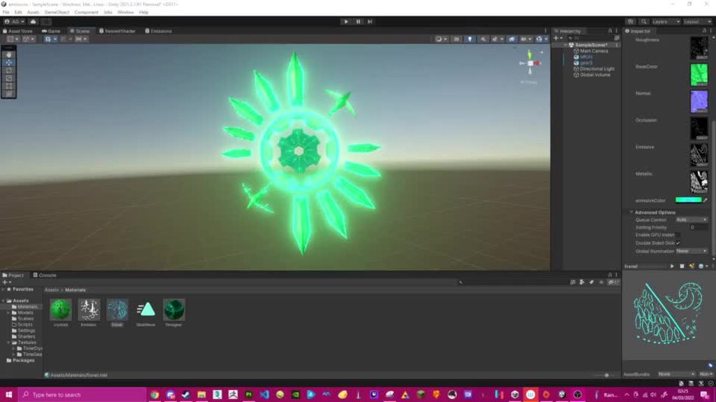
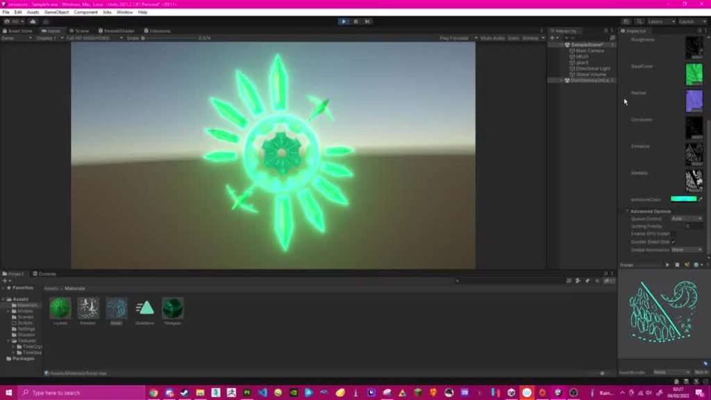
Is it possible to make a shader that renders pixels differently depending on whether they're inside a specified mesh, or outside it?

I'm looking to apply the same effect as the pixel perfect camera component, but only to specified sprites - is this effect possible with a shader?
Use case is there are certain objects that I'd like to be rendered as crisp pixel art on the grid, even if they're rotated, but I dont want it applied to my entire scene.
Here's the desired effect, but using the pixel perfect camera

Thanks :)
@sonic hawk use scritable render pipeline or command buffer to just pixel one piece of image is the way
How to add steps to Unity’s graphics pipeline using a selective bloom effect as an example.
I want to change the colors of the car, what you see is a texture, how can I manipulate the texture colors? and if someone has a tip on where to start i'd be greatful

2 options that are coming in my mind :
1 : You should give 2 different IDs and so create 2materials and modify one of two.
2 : Create a mask on your material and then modify the color thanks to your masks
I want to create a shader in shadergraph that combines different textures but the amount of textures can change dynamically at runtime. Does anyone know where to start I have already looked at texture array a bit but dont know how to proceed from there. Is this possible with shadergraph or should I write the shader with code
Does anyone know why the output of the "Position" node when set to "world" is dependent on the viewer position?
Eg
Yknow what I figured it out, HDRP uses camera relative world space because HDRP needed to be even worse
With the Main Preview window it rotates the object itself, not the camera around it, which is why it looks like that.
But yes, HDRP also has camera-relative rendering (apparently helps avoid z-fighting due to precision issues when further from origin). Use "Absolute World" space on the node if you don't want it to move with the camera.
Could've sworn Absolute World was still camera relative 5 minutes ago but apparently it isn't. That makes it significantly less irritating of a feature. Thanks
Definitely wish they documented that more up front and centre
anyone knows any good book or online course on shaders that they can suggest me?
How do i get instance id into the frag side of a shader DrawInstancedIndirect,im fairly shore the regular way doesn't work because they don't use the normal id. I tried putting it as an extra parameter in the v2f struct but that gave me a error
https://paste.ofcode.org/mqH3KgCcsWNSbFnbxXFNYY my indirect shader
            fixed4 frag(v2f i) : SV_Target {

                fixed4 OUT = UNITY_SAMPLE_TEX2DARRAY(_MainTex,float3 (i.texcoord.x,i.texcoord.y,_Properties[this is where i need it>>>>>>>>instanceID<<<<<<<<].tex));
                fixed4 OUT2 = fixed4(OUT.r, OUT.r, OUT.r, OUT.a);
                OUT2.rgb *= lerp(fixed3(1,1,1), i.color.rgb, OUT.g);

                return OUT2;
}```nvm its still not working but i think i have this bit working
Is the Y value from the UV going bottom/top or am I not seeing something here?
Depends, sometimes things are upside-down just for funzies.
See UNITY_UV_STARTS_AT_TOP here: https://docs.unity3d.com/Manual/SL-BuiltinMacros.html
Can I force it to start at top? With a shadergraph
Firstly, see the top section here: https://docs.unity3d.com/Manual/SL-PlatformDifferences.html
I'm thinking/suspecting that SG translates that stuff for you if you use the sample node, thus you can assume it starts at 0,0 being the lower left corner.
@vague sinew
Thanks! I'll take a look
One way to test it is to just output the UV values as a color. You'll get various red/green shades from black to yellow. You can always invert your Y value if you need to for your math.
What I'm unsure about is if you pass a render texture as a texture to SG, what you may need to do, since it will be inverted on some platforms, but you may want it inverted. 😉
P.S.
This is why I'd love it if either Open GL or D3D died, so we wouldn't have to worry about this wonky stuff. And I'd rather keep D3D, but I'm biased.
What's SG? shadergraph?
yes
sorry im a completely beginner to shaders
A detailed introduction on how to use Unity Shader Graph (including v10+ changes). Graph setup, Data types, Understanding Previews, Properties, Keywords, Sub Graphs and more!
Hey anyone know a way for me to get access to compute shader shader model 6 stuff?
(IDK about model 6 issue)
But to the other, why render the Accel Struct at all? I assume it's an AABB tree... that can get complex to show.
P.S. if that's you in the GP discord, I liked your outdoor scene with the added cube-light.
yah thats me
Ive bee workin on this, trying to make it easy to use, and putting it up on github for others
and thank you! You talkin about the san miguel scene?(large tree?), I managed to get it to run at 30-40fps with its 5.6million tris, currently trying to pursue anything else for added performance(without much result tbh)
I wanted to render the AABB to try and see where its dense-ist to try and optimize the BVH building(no luck there tho turns out)
I was talking about #390264006402899979 message
The outdoor ?veranda? with tables.
yep thats San Miguel 2.0
hello all
how do i make white in a shader?
this might be an odd question
i've got some color properties in my shader
but i'd rather this be a constant
colors appear to be represented in fixed4 so i've made a fixed4(1,1,1,1)
but that shows as black

so i'm not sure exactly what's different between the color property that works correctly and my fixed4 that renders black
does that even compile 🤔
it seems to, yeah
I thought it needed to be = fixed4(1, 1, 1, 1);
this doesn't compile
so the 'white' color (that shows black) is being applied to the top-facing normals as intended and u can see that the shape of that is as expected

try just straight up setting the output to that instead of using a variable
so o.Albedo = fixed4(1,1,1,1); does show white

So the issue is with logic elsewhere
im going to try moving the assignment
does returning _White also output that?
returning _White seemed to show black
oh it seems to be working now
so the problem seems to be that i couldn't do fixed4 _White = (1,1,1,1);
instead i had to do
fixed4 _White;
_White = fixed4(1,1,1,1);
how to make the water ONLY refract the surfaces below the water

nvm problem fixed
Where is GlobalFog shader or script?
GlobalFog.cs?
ok not fixed fully but....
the refraction looks better now but still affecting surfaces ABOVE the water

do i need to use a scene depth node?
Maybe catlike coding can help https://catlikecoding.com/unity/tutorials/flow/looking-through-water/
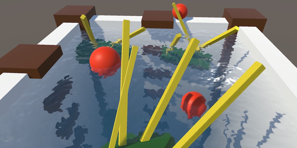
A Unity Flow tutorial about underwater fog and fake refraction.
But yes you need to do a depth check
Does Shader Graph support storing a result in a variable so that I can reuse it elsewhere in the graph?
which one should i actually use?

No, but I created a tool that adds it. https://github.com/Cyanilux/ShaderGraphVariables
It's basically some subgraphs that automatically connect based on variable name string, and makes connections invisible. And hijacks the "synonyms" field saved in SG files for serialisation.
for the refraction
Oo this looks very interesting, thanks!
To make sense of this, we have to realize that (1,1,1,1) is just a math expression, or several expressions separated by commas, like in the C language. Although I'm surprised that it didn't assign a result of 1 for some reason, I'll have to think about that one a bit. But the point is that is IS NOT a vector notation. Ever.
Whereas the fixed4(1,1,1,1) is a constructor call, for the fixed4 data type (a vector) passing arguments of all 1's. And notation for function calls also happens to use parentheses for parameters/arguments, but in that case it isn't math-grouping.
P.S.
fixed4 _White = fixed4(1,1,1,1);
would work all on one line. Technically,
fixed4 _White = 1.;
should also work, which is why I need to figure out why (1,1,1,1) didn't evaluate to a 1.
i see
I think it's because it was defined outside a function, and that's treated as a global shader variable passed in from unity, which always default to 0 as it's non-serialised and has to be set from Shader.SetColor. If you don't want it to do that you need to mark it as static, or could use a macro, e.g. #define _White fixed4(1,1,1,1)
So you're saying fixed4 _White = 1. won't be 1's but would still end up being zero unless later initialized in code because it is not serialized?
When outside any function scope, yes
But I think static fixed4 _White = fixed4(1,1,1,1); would work.
(Though it's not something I'd really use - I'd just write fixed4(1,1,1,1) in the function wherever it's needed)
Yeah, right. That's probably why I never hit this.
Because the statements (1,1,1,1) evaluate, from left to right, one at a time, as a 1. So these two statements should be equivalent:
fixed4 foo = (1., 1., 1., 1.);```And for @arctic flame further discussion,
This (assume inside a function)
fixed4 foo = (1, 1, 1, .5);
evaluates to an expression equivalent to
fixed4 foo = .5;
and results in a fixed4 vector type having (.5, .5, .5, .5) and can really throw you for a loop due to the notation that the compiler cannot detect since comma separators and parentheses are valid in C.
that explains why it compiled
is there a practical utility in seperating some expressions with commas like that or is it just a quirk of the syntax that it happens to be allowed
Mostly the latter.
But in C, and in shaders, the comma notation is handy for things like loops.
For example
for (uint i=0, bool done=false; i<50 && !done; i++) {....}
so that first expression in the for loop has TWO initializers separated by a comma.
oh, i didn't know that existed
That's c notation btw, I'm not sure how/if that would work in HLSL, but you get the idea. Comma separators allow multiple expressions to be done in one "statement". Mostly, it's an invitation to buggy code, but it comes in handy and is often used for things like loop initialization.
And it's not really a quirk, it is unfortunately intentional. Although really, for any situation I can think of, it can be done at a different point without commas, and would be clearer. C is (in)famous for it's compressed notation, but sometimes it's a bad idea.
Does anyone have any idea how Valheim does its coloured lighting? It appears to be some kind of volumetric fog. You can look in one direction and it's a blue atmosphere, then you can look towards the sun and the trees are surrounded by an orange light. It's not necessarily realistic, but it creates some very picturesque scenes.


It's quite scary at night - it doesn't just get dark the way it does in other games. It gets black, like scary black, almost like you're being surrounded by a black fog. It fills in around the trees but doesn't seem to obscure the sky
Valheim was made in Unity btw
@thin bear I believe a combination of post processing filters and literal colored lights could create a similar effect
But I'm not a god of light, so you might want to wait for the opinion of someone more legendary
Hi guys!
i made this shader in unity 2020.3.24, and now i need to use in 2020.1.17, any way to convert it?


Love that art style.
Skybox-aware volumetric fog, DOF, etc.
IDK if they did a custom lighting solution or not, but I wouldn't be surprised. URP isn't very volumetric out of the box, but HDRP is. URP could have custom shaders for that though. Or maybe it's built-in pipeline, with custom volumetric lighting. Whatever it is, it's a bit toon-ish, low poly, and begs for a water-color look (IMHO) but the lighting and atmospheres look FANTASTIC.
I wish I had a better answer for you, like an interview with the game developers discussing it, but I haven't found one that has programming details. Only reviews, or content/platform info (all which are uniformly positive).
According to this, they're using effects/options that are fairly standard in Unity/industry:
https://guides.gamepressure.com/valheim/guide.asp?ID=58006
Whatever it is, it's high quality artwork, and apparently deliberately lower-res textures and low-poly, as I'm sure you know. I think 75% of it is in the artistic work, not the shaders per se, with shaders contributing nice touches like skybox aware volumetrics, wind, floating streaks, etc. I've also read that many things are procedurally generated and it tends to be CPU heavy.
I think I'll order it on Steam, just to play it a bit and look at the visuals even if I don't finish it.

Game Guides
can you make shaders paint outside objects? how can i make a shadow effect below an object?
Can shaders draw outside of its mesh? No. For shadow you can either use actual shadows or google ”unity blob shadow”
can I make a drop shadow for an object where it only appears when behind walls + objects?
i.e. it only renders if it's behind something
i recently found out you can just use 2 pass shaders where it draws a transparency always and when it's not behind an object it draws the full opacity of the object. I didn't see how you can only do it for when it's behind an object
Is there a way to use shaders to make meshes render as a solid color when viewed from inside?
behind walls and objects? yes
but then they're always drawn over everything
@serene elk You know how when you move a camera inside a mesh, the mesh disappears? I want it to appear as a solid color on the inside... does that sound doable?
Sorry my knowledge of shaders is very limited
you can but apparently it's a performance hit
https://answers.unity.com/questions/8224/transparency-and-backface-culling.html
Unity is the ultimate game development platform. Use Unity to build high-quality 3D and 2D games, deploy them across mobile, desktop, VR/AR, consoles or the Web, and connect with loyal and enthusiastic players and customers.
Unity is the ultimate game development platform. Use Unity to build high-quality 3D and 2D games, deploy them across mobile, desktop, VR/AR, consoles or the Web, and connect with loyal and enthusiastic players and customers.
Hey smoll question, I am trying to put the purple image on top of the one with the squares. Any idea what I would need for it? I am a Shader noob and I can't figure it out


You can use a Lerp node for this (or Blend node with Overwrite mode, ends up as the same thing). But you'd need to turn your texture result into a black/white mask for the T input. There's a number of ways to do that : If it has an alpha channel can use that (the A output). Alternatively could change the texture to have a black background and red shape rather than purple and use the R output. Or could use the Color Mask node (though that may be slightly more expensive).
For the A and B inputs of the lerp, you'd probably use the squares result and a purple Color node/property.
oh sick

perfect
2nd method wouldn't work as well because it is meant for a character that changes colors often and has some components that have to not be effected which makes it hard
Shader Graph v10.3+ introduced some newer texture struct types which allow you to pass the sampler state attached to a texture through to the function. Can change Texture2D in your code to UnityTexture2D and remove the SamplerState input. Instead of samp, use tex.samplerstate.
Alternatively, you may be able to change the input type on the Custom Function to "Bare Texture2D" instead which means the code should work without those changes. (But can't quite remember if those bare options can be selected or whether you need to enable them in Unity's Preferences -> Shader Graph maybe?)

That's why I suggested to not use the texture output for the A/B inputs.
Since it's a single colour you could just use a Color property then have control over it from the material inspector (rather than having to swap out textures just to change it)
oh, I missed that hold up
Making the texture have an actual alpha channel instead of a white background would also stop it bleeding to white at the edges. But I feel it's a little unnecessary to have a full RGBA texture just for something that could be imported as a single channel texture to save memory.
Basically this texture will become an RGB Texture later down the line. the purple and yellow will be replaced with Red and Green. but there are a lot of other colors in there that have to be put on top of this which is why I kinda need all 3 channel colors

with both the gray being blue-ish, the mouth being red-ish and the other red parts there are to many colors to just add into 1 texture which is kinda the issue
unless I am miss understanding where you are coming from Cyan
Your original question didn't mention this texture, but if you are using the other channels then it's fine. I guess what you were doing before was just for test purposes?
I know, which is why I brought it up now because I understood the confusion
my bad sorry 😅
but yea, it is for testing while my artist friend is working on it
also do not worry too much about it being super optimal, it is meant for 1 character in the entire game only
Thanks for the detailed reply, yes I feel like the answer is in some kind of volumetric light/fog, since the different lighting seems localised to areas physically around the player that change the colour atmosphere that you look through, not just the surfaces that it hits.
Wow I think I literally found what they did. If it's not this library exactly, it's got to be the same technique...
https://github.com/SiiMeR/unity-volumetric-fog
@meager pelican btw the game is just an awesome adventure on multiplayer, I highly recommend having someone else join in with you when you do play it, experiencing everything for the first time.
Ty for the answer, when I use tex.samplerstate, i get another error.


You don't need it in the function params, just in the SAMPLE_TEXTURE2D_GRAD parts
Unless you want to be able to override the SamplerState that is (then I think it's UnitySamplerState sampler in params, then use the sampler in the sample macro)

Since the sampler is combined with the texture you need to remove the Sampler input port from the Custom Function node too (in Node Settings).
Thank you very much
can I not put a Pass {} code block in this?
https://gist.github.com/Davidj361/e0439f7ec228c2769ef05d47bdc1e3e2
If I'm passing an RWStructuredBuffer to my compute shader, and theres say 10000 elements in the buffer as an array, is it safe to use id.x to retrieve them?
edit: no use id.y * WIDTH + id.x because it will only use index up to the length of your screen 🤦♂️
i haven't really found a way to make a water depth
i mean i have to make my refraction to only refract surfaces below the water
and that can use scene depth but i don't really know how
trying to find a solution here!
is there no proper extension for formatting .shader files in Visual Studio?
im trying to lerp the refraction with the base colors, why is this happening?


is it possible to instantiate geometry in shader graphs? I mean I could have it for outline shader because outline is another geometry to which black color is applied hehe
though parent geometry remains visible so there are 2 geometries where 2nd is an instance
how do I do it?
can anybody tell why this is happening?
For a compute shader, you dispatch it with args, it's not about screen width. Make sure you check bounds on whatever your resulting index is.
Hello,
I have made a shader for seamless textures, but sometimes I switch it to static mode (instead of Absolute World position I set it to Object) and it does this to me. Is there any real chance to fix it? (Shadergraph)
Preview -> https://ctrlv.tv/Jrhw

Fastest screen record online
Fastest screen record online in browser only without addons.
Maybe try googling "Triplanar shader graph" and see what you get.
Not enough info to know how to fix it right off.
perefct work for Absoluteworld but object make this shit :/

Nope.
You can generate geometry with compute shaders in Unity (that SG doesn't support yet) and then use a draw instanced indirect type of call to draw it. Drawing it could use the SG shader though, I'd think. But instancing MIGHT be an issue.
Huh, what is "IsStaticObject", is that a normal node? Or a custom node?
Boolean for switch between static object in world and movable object
Oh, I get that. 😉
I was looking for the code, like, are you sure it is returning what you think it is? That it is working OK?
What do you mean?
Maybe output the results of that to some colors (remapped if necessary) and see if it outputs the same thing when the object is located at 0,0,0 for static and non-static.
I mean is that a Unity node, or a custom node?
Maybe it's a unity node. Cyan will know.
He's typing.
lol
The Triplanar nodes also have a Normal input which you've hidden. If you're changing the space you'll probably want to change it for both Position and Normal.
Ah
@regal stagJust for my own edification, is "IsStaticObject" a stock node? (Thanks in advance) I searched but didn't hit a result.
I think it's just a Boolean Keyword (which is equivalent to multi_compile/shader_feature in shader code)
So how do I do that? I'm just getting started with the shadergraph, so I'm getting lost in it
Huh, I didn't know they used that keyword. Thanks 🙂
The fact that I have hidden things there deliberately because it worked for me before I just added staticObject views there
It's likely a custom one that then gets exposed as a tickbox on the material
First step would be to show all the inputs (if you don't know how to do that, hover over the node there's an arrow in the top right iirc)
Then you'd basically do the same thing you're doing with the Position input, but with the Normal input and two Normal Vector nodes (set to Object and World space that is)
Okay I will try it. I'll call you what I did wrong, but I hope I understood correctly
How do i add a texture to my material
Normal Vector has only World
when I set it like this (see screenshot) it already works in the scene (the shit doesn't do it) but it seems that normal texture doesn't work (Screen n.2)


I'm not really sure what is causing that
But I'm well done, how did you advise me, right?

Yeah
I see that there will be something else when I have the plane set to rot 0 0 0 so it looks good, but as soon as I shoot it, normal will disappear


Rotation won't matter to object-space normals. But the light direction calc won't be the same as it is for world-space (which include the position, translation, and scale).
Maybe you want the object-space colors (texturing) but the world-space normals. And maybe that's what you already tired before. I'm confused as to what you're doing.
P.S.
Why do you want object space normals anyway?
You want object space textures, so you'd use that for triplanar mapping, then try a world-space normal so you match the scene. That would, internally, do some kind of objectToWorldNormal matrix multiplication upon the original object-space normal.
It is clear to me that this will not affect me. Rather, I try to make sure that some world objects do not have UVmapping and I use them flatly (static in the world and at the same time as moving (eg when stones fall)) so I wanted to make it easier with a shader by adding an objectPosition with the fact that it can be moving and not moving object texture on it
For my dispatch args im doing screen width/corresponding thread count. Should I use buffersize/threads?
Depends on your code, and what you need. But normally if I'm passing a buffer, and I wanted each core to deal with one item in the buffer, I'd pass buffer-related sizes. OTOH, if I'm processing a texture, I'd do it that way, with texture related info. If you're trying to do both at once, I cannot answer you because "it depends".
Sure, I’m passing a buffer as well as a texture and the buffer size can get massive, so id.x wasn’t going into the buffer at all. Doing screen width * height works but only up to ~2 million indices of the buffer
Which is still probably fine I just didn’t know if there was a different indexing/threading method, I’ll experiment a bit though
I'm trying to create a sun in the sky. using shader graph.

I can get this, but it sort of broken.
I'm following this https://medium.com/@jannik_boysen/procedural-skybox-shader-137f6b0cb77c and using this for the sun
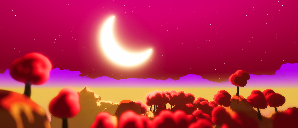
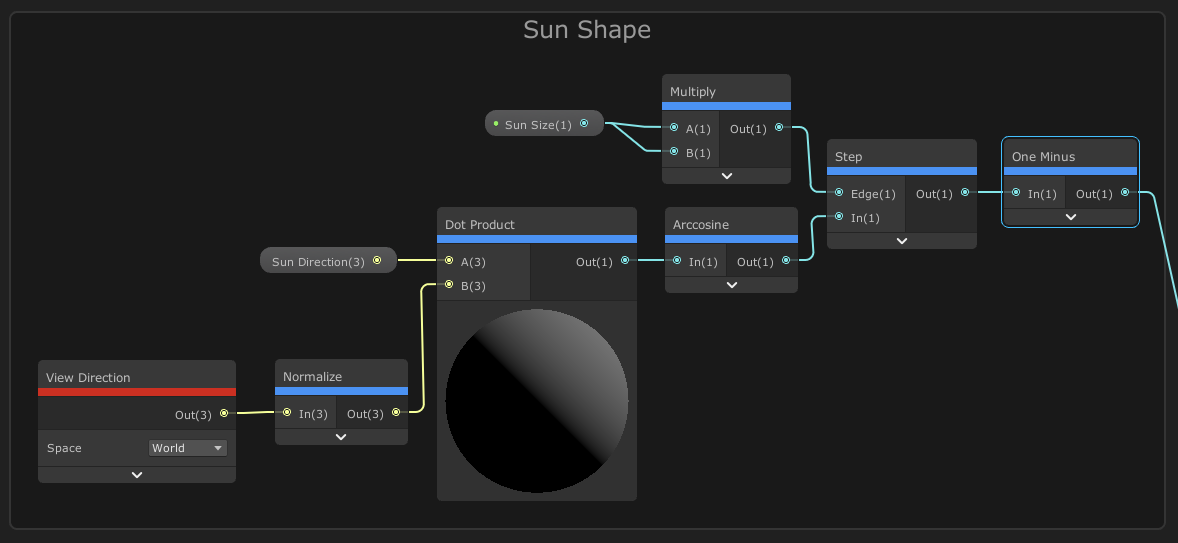

However, there is a weird bug where I can't control the size of the sun, and there is two suns.
I was wondering, is screen position node broken in shader graph or something?
Hello, is there a way to cast shadows on a Unlit Shader?
Seems like an oxymoron
If the shader reacts to lighting conditions, it's not unlit
i mean, using Shader Graph and Custom Functions, im not talking about setting the material to cast the shadow
Is there a way to get shadow information?
@abstract stirrup I have some custom lighting functions / Sub Graphs including one for Main Light Shadows here : https://github.com/Cyanilux/URP_ShaderGraphCustomLighting
Obtaining shadows also requires some keywords set up in the blackboard (if using a custom function that is. The subgraph should already handle it for you, though I know there's been some bugs with keywords in subgraphs in more recent versions iirc)
someone knows why cant find the Depth Fade Shader if i have URP?
tysm
what package cointain deph fade
hello, anyone knows how to write .hlsl code on a mac? Visual Studio does not seem to support the syntax
or .compute - found some open source using this stuff, it runs and compiles fine, but almost impossible to write code, as VS is not more helpful then any other text editor in that case
Hi everyone! I've been trying to code a shader which let's an object be illuminated by point lights and it seems to work very well, except that the shading doesn't update if I move the point light around

Here is the code: https://paste.myst.rs/wbfwc6oo
a powerful website for storing and sharing text and code snippets. completely free and open source.
I'm still figuring out how shaders work 😄
I'd think this problem was solved ages ago but I can't seem to find anything on Google. I am trying to render the player's gun in front of everything else in an fps game. But the most common solution I can find is to use 2 cameras, one that renders only the gun, and another to render the rest of the world, and overlay the gun on top. Unfortunately this prevents shadows from being cast on the gun by the world, so how can I fix that?
Also, is there a way to either: clear the depth buffer during a shader pass, or write specific values to the depth buffer, ignoring the actual pixel's depth?
I have a problem that I think is simple, but I don't know how to solve it
I want a different alpha value for shadows than light
on a material
Basically, I want the material to be transparent except for the shadows
Could I do that using shader graphs?
Hi do you know why when i always try to create a shader it never compiles? I have no errors in the console
