#archived-shaders
1 messages · Page 233 of 1
It would help you to practice with some tutorials so that you do know what you're doing
There will be plenty more challenges ahead
You'd basically need a function to convert from HSV to RGB. This tutorial should help : https://www.ronja-tutorials.com/post/041-hsv-colorspace/
Or could copy the HSV->RGB function that Shader Graph uses, https://docs.unity3d.com/Packages/com.unity.shadergraph@12.0/manual/Colorspace-Conversion-Node.html
How can i get the object bounds in shader graph ?
i need to offset something in my shader to adapt to any object pivot so i guess i need the bounds info
something similar to this node in UE : ObjectLocalBounds

I am working on adding a desaturation shader in the project I am working on and am finding that other UI elements that are behind the plane with the desaturation material are not . Is there a simple way to apply the desat to the UI elements that I am missing? Currently i have tried sorting canvases, sorting render layers and can get the ui elements hidden but that is not the effect I am going for
im bad at reading shaders
which part of this unity shader accoutns for shadows?

GitHub
Unity Graphics - Including Scriptable Render Pipeline - Graphics/CombinedShapeLightShared.hlsl at master · Unity-Technologies/Graphics
Hi! Does anyone know how Material.ComputeCRC() works?
Looks like the blade is rendered twice and have z-fighting, do you have culling disabled?
Unity doesnt give you that information for shaders. You have to make properties for those values and set then usijg c# script
How do I write to the _ShadowMapTexture buffer??
im working through the patreon instructions, but mine already looks nothing like theirs, even though we have the same blocks. Any idea why?

you seems to be dividing by zero here. you could change the default value of the property so you don't get that division by zero

i fixed that, it still looks different

oh hold on let me put the first node back
there

the result depends on sphere radius and sphere position. you should use exactly same default values as they do if you want the same results
they dont list the default values, and the first node isnt affected by radius and it still looks different. Ive tried setting the vector3 to 0,0,0 , 1,1,1 , 40,40,40, but none of them worked

Im currently making a light beam effect for a movie projector and this is what i have so far with an unlit shader graph. Is there a good way of making the end bit fade out? so that its not as abrupt?

Pretty sure they use (0,0,0) but the difference is due to the 3D/sphere vs 2D/quad previews. You should be able to override it to the 2D one for your Distance node in the Node Settings (tab on Graph Inspector window). Assuming you're in a version which has that option, can't remember when it was added (v11 maybe?)
Otherwise using a value of (0,0,-0.6) should move the dark point roughly to the front of that sphere in previews.
Make the end more transparent. I'm not sure how you're handling the gradient along this currently but remap the values a bit. Or if it's a texture have the edges fade to black / alpha of 0.
How could I make the line's caps (like the end and the beggining of the line) rounded? I'm using 2d unlit sprite URP. Help would really be appricated 🙂

The "Segment" sdf from here should give what you want : https://www.iquilezles.org/www/articles/distfunctions2d/distfunctions2d.htm
It's written in glsl so you'll need to convert it to graph form or hlsl and use a Custom Function node. (Mainly just vec2 -> float2, could replace the clamp with saturate)
Can then subtract a value from the dsf result to make it thicker/rounded, as explained near the bottom of the article.
Or just use a dot product node, super useful function https://youtu.be/sD6y-hUxEck
🤔 but then you’d need some kind of stencil for the end cap..
Or maybe the above suggestion is better, idk
Works great man many thanks to you
I have a displacement map that I exported from Substance Painter, but it seems like the shadergraph wants nothing to do with it. I'm using URP and it has to be OpenGL compatible because I'm making this sim for the quest. Here's what my mesh is looking like with & without the displacement currently. Not sure what's going on here


here's what I have now in the graph, not sure if I should be doing something differently - a lot of the youtube tutorials on displacement are either old or not OpenGL/URP compatible

You're replacing the Y coordinate, I'm pretty sure that what you need to do is to add the displacement value to the Y coordinate instead
Or maybe even do a "push" operation : add normal x displacement to the position
the add worked pretty well! one of the pieces of the mesh doesn't want to move with the rest of it but I'm going to make sure my UVs are correct there first
Is there a reason to displace the mesh vertices with the vertex shader and not simply have this displacement baked in the mesh directly ?
since it's in VR there's going to be some LODs, so we wanted actual vertex displacement when the player is looking super closely at the ground. There's some rocks, wheel treads and footprints in the dirt so we figured actual vertex displacement would be beneficial for LOD0
My point is : vertex displacement isn't adding more geometry anyway. If it is static and you have LODs anyway, I would recommend to just bake that displacement into the vertex positions of the mesh :
- less shader computation as it's already displaced
- you will profit of better lighting as the vertex/faces normals will take the displacement into account, that is not the case currently in your setup
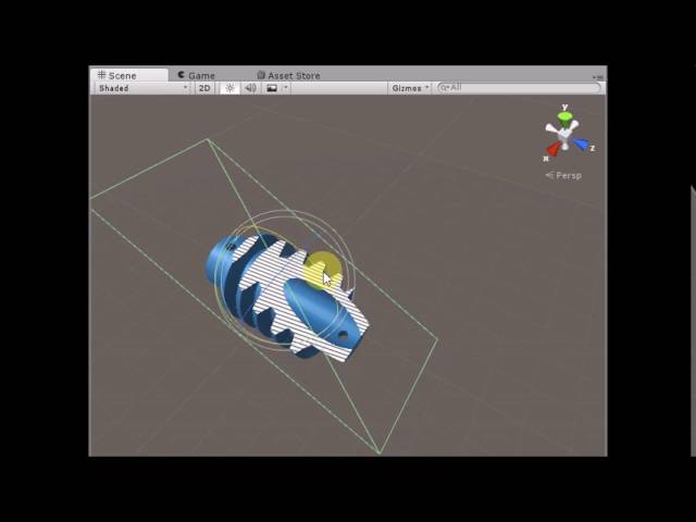
So I want to create an intersection shader similar to the one displayed in this video.
Unity3D Cross Section Shader
Live Demo : https://dandarawy.github.io/Unity3D-Cross-Section-Shader-Demo/
Download from asset store:
https://www.assetstore.unity3d.com/en/#!/content/66300
Github:
https://github.com/Dandarawy/Unity3DCrossSectionShader
But from the looks of it, the intersection is drawn on the back faces of the mesh, which mean lighting and sorting (like objects inside the mesh) won't look correct.
Is there anyway to figure out the intersection between the plane and some given object, and then display some texture on the plane where there is an intersection.
my weapon does this when under heavy light, any idea why?

The issue is there's no actual geometry for the shader to draw without it being a geometry shader. Maybe a hybrid approach? Have a separate quad mesh with the texture on it that you draw and two shaders:
- One that culls things as per the video?
- One that culls bits of the quad that don't intersect with the main mesh?
What is "this" exactly? How's it supposed to look?
how do I get the texture width/height when passing a texture to a custom function in shadergraph?
the blue parts are supposed to be white
texel size node
I have to pass it from the graph? I meant is there a way from inside the function
I'm still wrapping my head around shaders, but would it be possible to like... have all the pixels that would show the back faces of the mesh write to the stencil buffer, and then have the shader on the plane use those values to draw the intersection texture?
and the position of the plane is used to alpha clip the mesh
Maybe. I'm not a shader expert myself either.
Alright because that was word vomit on my part 😛
If you are using the "better" texture struct types added in v10.3+ (e.g. UnityTexture2D in this case) you can use .texelSize
@shadow locust do you have any idea what could cause that?
@shadow locust @regal stag thank you both ❤️
I think the main problem is knowing like the UVs for the texture at the given position (and lighting if you want it lit). Since there's no geometry there's no way to calculate that
I can still use the UVs of the Plane though
if that's available to you then yeah that can work
One last Q, if I want to iterate through the pixels of a texture, I came up with this mess but is there an intended way to iterate over a texture?
float2 uv = (float2(x,  y) + 0.5) * texelSize;
float4 data = SAMPLE_TEXTURE2D(Tex, SS, uv);
You may be interested in this : #archived-shaders message
ok, ive implimented to effect, but its still not quite what im trying to achieve.
if the scene looks like this normally:
then it should look like this when the effect is on:
ive kind of found a similar effect online but i dont think it works anymore, as the shader merely shows up as pink: http://halisavakis.com/my-take-on-shaders-spherical-mask-dissolve/


this being in a 3d environment of course, not 2d
And this effect hides objects outside the sphere, weather the camera is inside OR outside the sphere, the effect remains the same
anyone know why this would be happening
If an object has 2 materials, is the order of operations...
- Vertex Function 1
- Fragment Function 1
- Vertex Function 2
- Fragment Function 2
or
- Vertex Function 1
- Vertex Function 2
- Fragment Function 1
- Fragment Function 2
probably the former, although this should not matter, as the materials wont affect each other
Won't affect eachother? Do you mean they will override?
Or more that it's just two separate processes?
the way materials work internally is:
- Pass the mesh handle (pointing at the mesh data in the gpu) that the material belongs to to the gpu
- Set the shader program of the material in the gpu
- pass variables and buffer handles (like textures) to the gpu
- render to the output image
How would one go about combining shaders? I want to use a disolve shader on an object that already has a complex shader, what's best and the easiest way to go about this? The object is made of multiple parts that have different shaders too.
and those run consecutively, not parallel
Is there any way to access the Stencil Buffer from Shader Graph?
can someone please help me with my shader issue it's making me pissed
Provide some more context
Well when under certain light sources my shader seems to change colors
Like inverted almost, white to blue
and what is "my shader"
.
Another example
^
I don't see a shader
The shader is on the weapon/screenshots
I can’t really send a pic of my whole shader but I could try and send some
What is the shader made in
Unity shader graph
Well, the problem is probably some logic in there
any rough idea what i could be?
its a problem with the white parts turning blue, so i can assume its


something around here
put a Saturate node in a few places and that might just fix your issue
where do you think? it would be best
So I'm trying to make a shader that writes all the backface pixels to the stencil buffer. I don't want it rendering anything.
This is the code
Shader "Unlit/BackfaceStencil"
{
    Properties
    {
    }
    SubShader
    {
        Tags { "RenderType"="Opaque" }
        LOD 100
        Cull Front
        ColorMask 0

        Stencil
        {
            Ref 1
            Comp Always
            Pass Replace
        }

        Pass
        {
            CGPROGRAM
            #pragma vertex vert
            #pragma fragment frag

            #include "UnityCG.cginc"

            struct appdata
            {
                float4 vertex : POSITION;
            };

            struct v2f
            {
                float4 vertex : SV_POSITION;
            };

            v2f vert (appdata v)
            {
                v2f o;
                o.vertex = UnityObjectToClipPos(v.vertex);
                return o;
            }

            fixed4 frag (v2f i) : SV_Target
            {
                return fixed4(1, 1, 1, 1);
            }
            ENDCG
        }
    }
}```Unfortunately it's producing this very strange and glitchy looking back area.

and when it I move the camera around it does strange things >_>
I was told that ColorMask 0 would just not call the frag function.
bro thank you so much! i fixed it
Hi do you know why this happens, i'm new to shaders ? I'm using the Unity custom lighting shader but it keeps saying this but it's working for others ppl


GitHub
A sample project showcasing a simple method to calculate custom lighting inside of Shader Graph for the Lightweight Render Pipeline. Includes a sample toon shaded scene and example assets. Built fo...

My third iteration of stylized grass sees the light of day! This time utilizing compute Shaders to process geometry and animation!
#gamedev #unity3D #shaders #URP https://t.co/M1m99Rj9rO
The triplanar node is based on texture samples, and as such, need a texture object to sample from.
If you're doing some kind of procedural (noise, sdf, you name it) texturing, you will have to implement the triplanar mapping yourself (do the mapping in the 3 world axes and blend together using normals)
you could use custom function and yoink the logic from here https://docs.unity3d.com/Packages/com.unity.shadergraph@6.9/manual/Triplanar-Node.html . Instead of sampling texture 3 times, you can make 3 in parameters for 3 different colors
i'm trying to blend two rendertextures respecting their depth buffers (i.e. things in front should be in front), they're rendered from identical cameras in the same position - could i do this in a shader or have i missed some more obvious way to render two cameras into the same texture with proper z-testing
As long as the second camera doesn't clear, there's no problem rendering a second camera on top of another. That's called camera stacking.
It's more complicated with deferred rendering though
yeah but it ignores the depth buffer / z value - i do have the clear flags set to depth only but the second camera draws on top like another layer even if on the same depth (camera setting, both at 0), like for example if a tall object is partially behind a short object, when drawn by the second camera it'll draw entirely on top of the short object which is on the first camera
unless there's something i'm missing?
Set it to Don't clear. Depth only means clearing just the depth, which will throw away the depth buffer of the first camera.
ahh yeah thanks i just didn't understand what those options actually meant
ok maybe someone has an idea, i have an "outline" shader, a object behind a wall has an outline and also the complete body has a color, for some reason i have to have 4 children that must be single objects (they move seperately) if i add the outline shader to all you can see the parts through the body, i need the shader to only draw the body if the GROUP of meshs is behind an object
anyone has an idea?
is that even possible ?
I want to define some point and clip all pixels that fall below the x,y,z of the point.
I tried doing it like this.
Pass
        {
            CGPROGRAM
            #pragma vertex vert
            #pragma fragment frag

            #include "UnityCG.cginc"

            float4 _MyVector;

            struct appdata
            {
                float4 vertex : POSITION;
            };

            struct v2f
            {
                float4 vertex : SV_POSITION;
            };


            v2f vert (appdata v)
            {
                v2f o;
                o.vertex = UnityObjectToClipPos(v.vertex);
                return o;
            }

            fixed4 frag (v2f i) : SV_Target
            {
                if(i.vertex.x < _MyVector.x || i.vertex.y < _MyVector.y || i.vertex.z < _MyVector.z)
                {
                    clip(-1);
                }

                return fixed4(1, 1, 1, 1);
            }
            ENDCG
        }
But it's not working, so clearly I don't understand how to use Clip well.
still a regular cube.

or wait what

it changes as I move the camera
You're doing it on vertex which is in clip space (well, probably NDC at this point) due to the UnityObjectToClipPos function (and perspective divide that occurs between vert & frag).
I'd assume you want to pass the object or world space coordinates through and compare against that instead.
Could also use discard; keyword instead of clip(-1); but they'd do the same thing afaik
what's the method to convert to unity world space?
mul(unity_ObjectToWorld, input.vertex);
I think
Yeah, though I'd probably use float4(input.vertex.xyz, 1); in the second param just to be safe
Maybe with stencils operations? (https://docs.unity3d.com/Manual/SL-Stencil.html)
e.g. Render your 4 objects to the stencil buffer, then render the outline (inverted hull?) testing against it to remove the overlapping parts
Maybe that explains it better

Ya that did it. Initially was I clipping based on like... it's position in screen space >_>
@regal stag i think that's the way to go, but somehow i can't get it to work
lessequal almost did what i want but the parts between the two got another color then :/
Question about the Stencil Buffer actually. I basically want to only write to it the pixels containing the "exposed backfaces" of a mesh. Basically if a front face is obscuring the backface, do not draw. The back faces will get exposed as I alpha clip the object.
But doesn't writing to/checking the Stencil Buffer occur between the vertex and fragment programs?
And I can only discard for alpha clipping in the fragment?
Basically looking to replicate this.
Unity3D Cross Section Shader
Live Demo : https://dandarawy.github.io/Unity3D-Cross-Section-Shader-Demo/
Download from asset store:
https://www.assetstore.unity3d.com/en/#!/content/66300
Github:
https://github.com/Dandarawy/Unity3DCrossSectionShader
Write exposed backfaces to stencil, use that data to draw on a plane.
I don't want to draw on the backfaces themselves.
Did you see that it's on Github @steel notch
I imagine you'd have to render it in separate passes, first with back faces to "set" stencil value, then front faces to "clear" the stencil value. Or like increment/decrement, or Invert with a readMask/writeMask in place.
Also did you see what I linked before? (as a reply to the last time you posted that video)
Yes I did. I tried that one out and I believe at least that it does write to the backfaces.
So ordering is a bit fucky.
Yeah it draws to the back faces but with UV coordinates aligned to the clipping plane rather than the regular ones
Ye. I want to be able to have other meshes INSIDE the one I am clipping into, so even if the clipping plane is infront of these inner meshes, they will always appear in front.
Since it draws to the back faces.
Back to just a general question though. If I discard a fragment, does it write to the Stencil buffer?
Or is the reading/writing to stencil purely something that happens between vertex/fragment.
If you discard that pixel won't test/write to the stencil buffer
I think the stencil test/write might happen before the fragment shader only if it doesn't use clip/disard. Otherwise it runs after. The same thing happens with ztest/zwrite
Alright so...
- One shader that renders back faces, clips and then writes to stencil.
- One shader that renders front faces, clips and then resets stencil.
- Shader for the plane that uses info in Stencil to draw.
Yeah. An alternative to using stencils might be to calculate the depth to the clipping plane and override it for back faces using the SV_Depth output. (Though I'm not entirely sure on how to calculate that right now. I guess it's kinda like ray-plane intersection)
Boy do I wish URP had multi-pass.
Tossing it multiple materials with Tiny shaders is kind of annoying.
Oh well.
Is the default value in the Stencil 0 or 255?
Should be 0 afaik
Why do i get the warning i should consider using multiple shader passes in URP if it's not even possible ?
How do I make it so the shaders only job is writing to the stencil and not actually... producing a value for the pixel?
Use ColorMask 0 (outside of the cg/hlsl block, in the shaderlab pass)
I tried that and the region became this odd black zone of DOOM that caused graphical insanity.
Maybe also with ZWrite Off?
wont that mess up ordering?
Actually I guess not since the plane will have the job of ordering itself
and the stencil literally just contains a number
If I am trying to manipulate the shader properties by script, which name am I supposed to use?

_MyVector

Might be the OnValidate method? I'm not that familiar with it so not sure when it gets called.


(1st, not Playing) (2nd, Playing)
Why is it that when i play the game the lights go like this? I havent done anything to the lighting or anything


When i play the game, its starts on a title screen then changes to this
You need to generate lighting for your scene from the lighting window
oh slick. tbh i never knew this, its just one day this started to happen. did u have to do this now after a specific Unity update?
I have a very basic question, just trying to learn:
I have a shader I'm trying to put on a texture, and it comes out grey. I know im missing something very simple...

Make sure the UVs are set appropriately. Put the material on a primitive to see whether it's an issue with your material or your mesh


Your shader has definitely been saved?
So re-saving crashed unity... reopened and it worked. So yes? Thanks a bunch
is there a way to keep the texture size the same regardless of the scale of the object?
Triplanar mapping tends to be the answer to that
thanks Vertx, ill look into that. Yknow I hope youre getting paid for this Vertx, ive seen you help so many people on this discord
Hello a little question - what is on demand remap for materials is supposed to ? For me it's just erases all the materials in the prefab
Also, how comes that some embedded textures in .fbx change tome and color in unity?
Hi, i have materials that remain pink, even after upgrading them to HDRP. The materials have autodesk shader. Has anyone had this problem too maybe?
Anyone know of good ressources on how to create skybox shaders with shadergraph ?
in shadergraph is texture 3d sampling are not supported?
hmm it seems i can't sampled texture 3d in vertex pass, well this is sad. . .

This might be helpful : https://jannikboysen.de/reaching-for-the-stars/
It's mostly the same as any other shader, except the skybox mesh has 3D UVs stored - that are actually the same as the vertex positions (Position node (Object)). Since they are 3D you'll likely need to handle the UV input on most nodes or it'll stretch through an axis. (Some examples of different ways to map them : #archived-shaders message)
(I would however avoid using multiple 'Skybox UV' subgraphs like Jannik does as that will do the calculation multiple times afaik)
You'll probably need to use SAMPLE_TEXTURE3D_LOD in a Custom Function
That's what i'm currently trying to do,
I Just forgot how to use custom function 😅
If you haven't figured out already, it allows you to remap the material slot to one of your choice (rather then the default lit on pretty much everything comes in with).
Honestly, I'm still confounded at why materials on imported fbxs are r/o. What is the point of making a new material but then restricting modification to it. I'm very curious about what unity devs reasons are for this.
Wait how can i use Tex3DLOD in custom function ?
float4 Tex3DSample =  SAMPLE_TEXTURE3D_LOD(Texture3D_input, Sampler, UV, LOD);
Out = Tex3DSample;
This giving me Intrisic Error
Hmm looks correct to me. Is the UV input is a float3/Vector3?
Vector3

It looks like you're using both Tex3DSample and tex3dsample there
oh . . . . . typo. . . . welp i'm dumb 😅
hmm.., I'm dumbfounded.., I'm trying to supply a matrix through a script using "Shader.SetGlobalMatrix" function. It works as intended on my custom skybox material but I also have a water plane in the scene and that one doesn't seem to use the matrix properly. I can see in the frame debugger that the values look correct but it starts flickering and doing random things on the water plane. Anyone else know what might cause this or have experienced similar issues with supplying matrices through scripts to a shader?
and to just clarify better what happens.., I'm constructing some uvs with the matrix (I'm using it to rotate a vector. Basically telling me where in the sky my sun texture should be applied)
This is what it looks like if I take the values from the frame debugger of the matrix and input them manually into the shader (This is what I want)

And this is what it looks like when I try to use "Shader.SetGlobalMatrix" in a script. As you can see the skybox is fine but not the water plane

Is the water plane using a shader graph or written shader?
oh yeah.., shader graph!
I tried putting the skybox material on the water in case there was something different about them but nope.., the water surface still glitched
Under the Matrix4x4 property settings (in Node Settings tab of Graph Inspector if in v10+) there should be an Override Property Declaration. Enable that and select Global
You shouldn't need to do this for any other types, but matrices have a slight quirk that they can't be "exposed" but are still treated as per-material by default so can be set through material.SetMatrix. I think the glitchy is due to how the srp-batching works.
yeah.., the tricky thing it apparently behaves differently from any other property as you mentioned. Thanks for the explanation 😄
Big thanks again! Would've taken me forever to figure out myself
This is interesting, why Tessellation Displacement have a separate input? normally we just apply the displacement on vertex position. So why tho?

and the weird thing if we apply any vertex modification directly into the vertex position input or vertex normal input it doesn't taking account the tessellated mesh
How do I find this shader to remove it? I am not good at shader and don't know how to search for legacy. I have hundreds of shaders from stuff I downloaded.

Another view

hmm.., is there a way to reference the same node at different spots in shader graph?.., to avoid spaghetti looking webs or duplicates of nodes (imagine a disjointed connection acting like a portal for example)
not sure what to call it but it's quite common in other node based software.., is there a way to do this?
Not built in, but I wrote a tool ~ https://github.com/Cyanilux/ShaderGraphVariables
aw that's a pity. Really cool of you to have that available though 🙂
ooh.., those colored groups is something that's been annoying me as well!
like.., you just zoom out a little bit and it's a nightmare trying to decipher what's going on
Unity should definitely buy your thing and implement it 👍
Hi guys, I'm trying to "categoryze" my properties on a shader graph, and the Unity manual said I can, but I can't find the option. (Unity 2020.3).

The docs suggest it was added in 2021.2 so older versions won't have it
Where I can see that? I was looking for it.
I just used the dropdown in the top left to change version. v11 has an older image and no mention of categories, while the v12 page does
I use gpu instancing to render sprites, but i want to use sprite atlas, so i need to pass proper texture coords. To do that i pass float4 to compute buffer to reproduce _MainTexST. I calculate this property through
public static Vector4 GetTextureST(Sprite sprite)
        {
            var ratio = new Vector2(1f / sprite.texture.width, 1f / sprite.texture.height);
            var size = Vector2.Scale(sprite.rect.size, ratio);
            var offset = Vector2.Scale(sprite.textureRect.position, ratio);
            return new Vector4(size.x, size.y, offset.x, offset.y);
        }
and then use it in shader with TillingAndOffset to get proper texture UV in fragment shader
float2 TilingAndOffset(float2 UV, float2 Tiling, float2 Offset)
{
    return UV * Tiling + Offset;
}

varyings.uv = TilingAndOffset(attributes.uv, mainTexST.xy, mainTexST.zw);
to render sprites i use same quad mesh and stretch it to sprite size.
But i get weird result (screenshot): there is 4 sprites on screen:
- two sprites on top (hair + body) rendered through custom render system + custom instancing sprite material (with passed _MainTexST property as StructuredBuffer<float4> mainTexSTBuffer)
- two sprites on bottom (hair + body) rendered through default sprite renderer mono-component + URP default sprite material
Hair and body sprites in both examples have the same position, both use sprites packed to unity's sprite atlas, but somehow sprites rendered through custom system have wrong hair position.
Also on second screen i see that texture from sprite atlas have made hair sprite a little shorter then body sprite, while both of sprite source have 168x32 size
Please help! 🙏


anyone know why its not transparent?

the preview doesn't support alpha but does it work in game view?

because connecting it makes no different
have you set the graph to be transparent and not cutout?
yes
You have "Allow Material Override" ticked, so make sure the material is set to Transparent too.
If you created the material when it was opaque it will still be opaque
Hey, so I posted over in general code but they recommended I post here. I have this mesh that I made using MeshTopology.Line and I wanted the vertices to glow so it is kind of like a moving grid of connected lines, so I made a submesh with emission and used the MeshTopology.Point display for it and added my vertices. But now the vertices don't all glow and they're poorly lit, it's a very weird graphical thing that I don't quite understand, can anyone point me in a good direction?


https://youtu.be/mnxs6CR6Zrk?t=192
Does anybody think they know a way to recreate this effect that uses the nearest lightsource for cel shading?

Let's figure out how The Legend of Zelda: The Wind Waker was able to pull off cel shading at a time when nobody else was able to.
🐦 https://twitter.com/JasperRLZ
💰 https://patreon.com/JasperRLZ
🤼 https://discord.gg/bkJmKKv
🌎 https://noclip.website
🎵 Jasper - Epoch ( https://www.youtube.com/watch?v=DDmzbYV0d9M )
🎵 Allister Brimble - Fluidity - ...
I'm not super experienced with shaders but I've noticed that not a single shader I've seen has actually correctly mimics this effect or at all really
thank you, yup it's a little weird, expecially when materials are not in the right mode after the export
The shader itself would basically be the same as any other cel/toon shader (should already be tutorials out there). But rather than using _WorldSpaceLightPos0 you'd provide it with a custom Vector property and set it from a C# script via material.SetVector("_Example", direction);, where the direction is calculated based on the nearest light, or main directional if not near to any. (Can probably ask in a coding channel for help with that part if required)
So I should make a script that changes an exposed "light" parameter to be the directional light if not close to any dynamic lights, and then to use the closest dynamic light if near one?
Yea
I could probably attach a trigger to the lights to do something like that, hmm
The other way I can think of is by doing constant distance checks which would be horribly inefficient
Quick question: say I'm making a 2D game and I want objects to affect the color of the background shader.
We'll say the color extends out in a circle with a diameter of n units.
What I really want is that when the color fields overlap they transition smoothly between the object's color values rather than just overlapping to produce the average color.
Do I reference the objects in the shader, or create some kind of manager object, or something else entirely?
hey whats the fastest/best way to get textures such as world space position and normal textures from a main camera and into a compute shader every frame? I remember the last time I tried to do this I couldnt get it to work
if anyone ends up knowing this please @ me
If you ise Vector3.distance yes it's horrible but if you use . Vector3.sqrMagnitude and an overlapping sphere with layer mask not trigger
Depends on the amount of objects to be checked. I wouldnt call Vector3.Distance horrible on modern pc. Using sqrMagnitude when comparing saves barely anything because sqrt is veery fast nowadays
I have been running into the issue of shadergraph shader not showing when in a standalone build. They do however show in editor. The meshes do show in standalone when a standard URP lit material is applied.
Things i have tested but did not fix the issue:
- Enabled GPU instancing on the materials.
- In project settings i added the shader to always included shaders.
- change the project settings shader stripping to keep all variations
It seems like something in the shadergraph shader is not compatible with instancing.
Would be great to know if anyone managed to fix or found a solution to this issue.
Roger that, thanks.
Is it possible to achieve something similar to UEs Runtime Virtual Texturing to blend objects in with the landscape?
^^ Got this covered with microsplat actually
Any idea why after being exported from blender all my textures become waaay darker?
blender is the upper one

anyone know why this is happening? im trying to implement refraction

You need to change a setting in blender for proper color. I'm not on the computer right now but will take a screenshot of the setting in a couple of hours (assuming I remember 😜) off the top of my head it's in the rendering section of properties, the color space section
I'm trying to define a sampler state that repeats the texture. I've tried pretty much all combinations I could think of...
Texture2D _MainTex;
SamplerState sampler_repeat_MainTex;
....
_MainTex.Sample(sampler_repeat_MainTex, uv)
---> Unrecognized sampler 'sampler_repeat_maintex' - does not match any texture and is not a recognized inline name (should contain filter and wrap modes)
Try SamplerState sampler_linear_repeat;. As the error mentions it needs to contain both the filter and wrap mode.
aaaaa thank you so much!
Thanks!
Just noticed that whenever I double click create one of those "funnel dots" in shader graph it converts the value to a float4 (if it was a regular float for example)
This seems like a huge bug.., or am I missing something?
I'm talking about these things

It only occurs on the Multiply node iirc. I guess the devs forgot to take into account the "dynamic vector-matrix port". I do also find this a bit annoying sometimes. But can put the output through a Float node first (or Split & Combine in the case of Vector2/3)
oh.., so it's whenever it's after an multiply node?
Yeah
ah yeaaah.., just tested it out
sooo weird though 😄
I can't say the word that comes to mind when using shader graph is "polished"
Soo many small annoyances
I mean I like it for what it is.., but sometimes...
hello there
want to translate this
v.vertex.y += sin(v.vertex.x +_Time.y) * 0.3...

but as you can see how i can do v.vertex.y = v.vertex.x in visual !!
Put the output of your Multiply into the Y port of a Vector3 node before the Add.
@regal stag ok i try
@regal stag i took time to figure how that's perfectly fine thks ..
is there a way to save the effects of a shader ( such as transparency & material color ) to a GLTF? I am trying to save these procedurally generated crystals.

@grand jolt Either use #💻┃code-beginner (as you claimed this was a "coding issue"), or use this. You know not to crosspost by now.
Does anyone know shader tutorials that would help to understand how to make creep like zerg in Starcraft 2?
Hey I have an idea for a shader but don't know where to start :d Can someone give me some tips how to accomplish this?

The electricity would be moving and inside the ball
Should i create a texture and distort it with noise or how would be best?
You could just use a noise function and draw fragments wherever the noise value is > some threshold
tweak your noise function and your threshold it until it looks like that
cull the fragment if noise is not over that threshold
I'm making an instanced shader, is it possible to get instance id in the frag command?
because when i try it seems to be returning 0
or null actualy
fixed4 frag(v2f i, uint instanceID: SV_InstanceID) : SV_Target{
    fixed4 OUT;
    OUT = tex2D(_MainTex, i.texcoord);

    #ifdef UNITY_INSTANCING_ENABLED
        OUT *= _Colors[instanceID];
    #endif


    return OUT;
}```I got the shape down, but my question is now how to make the noise go from center to the edge of the circle?
You should add UNITY_VERTEX_INPUT_INSTANCE_ID to the v2f struct, use the UNITY_TRANSFER_INSTANCE_ID(in, out) macro in the vertex shader, and UNITY_SETUP_INSTANCE_ID(in) in frag. For full example see : https://docs.unity3d.com/2021.2/Documentation/Manual/gpu-instancing-shader.html
hi, is it possible to make shader that can blend the normals when object comes in contact with other and also recieve shadow at the same time?
unity 2018
what's the effect you're going for
@shadow locust it is ok if the shader is opaque i just want to blend diffuse and normal values on points of contact or intersection
should be doable, use deferred rendering to get screen normals, or calculate them from converting depth into world space and that into normals using multiple samples
but it will only blend on one material
if its fine
Iam sorry if this is the wrong Category but i have a problem with my Sprite Mask in a 2D Topdown Game when iam using a sorting Group cause it just wont apply.
I'm sorry. I tried to repro this issue (I've had it before) but my previous solution seems to not be working. I did see a bug reported about it to blender fwiw
wrong color space?
what does that means ? ^^
thank you anyway, I manually correct all the materials but htat's quite boring and long
Set your unity project to linear color space
thanks that helped!
I'm having an issue in Build that doesn't occur in Editor.
I have a RenderTexture, but its either black, or completely invisible in build, but normal in Editor
I've tried changing its Color Format field, I dont really know what most of them mean, but trying them at random, my render texture is sometimes black, sometimes not visible at all

I am using the URP which may or may not be affecting it
Does anyone know why a Render Texture might be black, or totally transparent in Build, but not Editor?
Please don't cross-post. If a render texture is black then perhaps .Create has not been called
What do you mean by .Create? It exists in the project folder, I can select it
What is the build target, where is it being used, etc
RenderTexture doesn't serialize in inspector to be able to drag in the project RT to that field. Ill try putting it in Resources and loading it.
Build platform is Windows 10, its being used on a Sprite Renderer

It should serialize just fine, though Create should be unnecessary if it's an asset in the project. Is it being used in conjunction with a camera or something?

Yes I have a camera that renders to it. Ill screencap the camera settings as well

That field would not show up in Inspector, so it definitely doesn't serialize
It should serialize, that's how it's visible on the camera, but that's besides the point. The issue is likely URP-specific
I can't see anything in the docs that would indicate you're doing anything wrong https://docs.unity3d.com/Packages/com.unity.render-pipelines.universal@13.1/manual/rendering-to-a-render-texture.html
How it looks in Build and in Editor. Editor is the expected appearance


Yeah I followed that doc when setting this up originally. It also used to work many builds ago, I don't know how far back it worked but it aburptly stopped working at some point
The most recent things I added are a Canvas for UI, and a second Overlay camera in the scene
neither of those things in any way interact with this render texture though
--
Going back through my builds, I was wrong, it was never working
I just mis-remembered it as working once
Which is helpful to know that it was not a recent change that broke it, it was never working at any point
"working" being in this case, rendering anything in Build. 100% transparent
showing up as a huge black square didnt happen until I started to mess with the camera and render texture trying to get it to show anything
Sorry, I don't know what could be wrong. Perhaps try posting your setup in #archived-urp and someone might know
Will do
How would you go about designing a shader like kylo rens lightsaber? I've tried do a vertex deformation shader, and it just looks like a mess. Any ideas?

Final reward lightsaber!
Usually glow is done in post processing state because it needs to draw to areas outside of the actual mesh. In unity glow post processing effect is called ”Bloom”. Also make sure to enable hdr
Is there any performance difference between dispatch and indirect dispatch?
Does anyone one know what this is called ? It's mostly used for fur shaders, I've been looking everywhere for an array like shader resembling something like this .

I've heard it called shells, and I can't think of another name off the top of my head
Yeah, specifically I've heard it be called "shell texturing". Fur shaders tend to use a "shells and fins" technique which additionally includes quads perpendicular to improve silhouette & hide some of the layering.
Can confirm on the naming Ive been trying to bang out a hdrp geometry fur shader for some time now
@vocal narwhal @regal stag @mental bone thanks for pointing me towards the right direction guys
hello, I'm new to the shader graph and I have a problem with understand why the main color switch from white into red can anyone explain me that a bit please?

because your multiply gives just single float, not float3
The light blue connections means the value is a float which is only a single component (red)
So the other channels on the split are returning 0
You don't really need to convert a float to Vector3 with Split/Combine unless you need to alter the channels. Just connecting the float to the Vector3 port will automatically promote it to (float, float, float)
hmm ok, thanks for help
There are many ways to represent colors on screen
Blender by default uses linear color space with "filmic" tonemapping
Unity by default uses gamma color space with no tonemapping
Blender's default settings make colors look washed out under most lights, so switching view transform to sRGB (or gamma color space) can give you a more informed look of how the asset will look in other programs
Switching to linear color space un Unity and enabling HDR tonemapping will give you a bigger color space to work with, but will also alter the visual color and contrast of assets
(I don't know if blender's filmic view transform is technically "tonemapping" but it seems to function the same way. Someone can correct me on that)
I'm not sure if gamma is the default in URP or HDRP any more because it's been a mistake of a default for a while and I was glad when they changed it
Ah, doesn't seem like it is
That's good


Because it's transparent but has ZWrite On
But that messes with the render order?


Hi, I'm working on a simple water shader.
I was trying to do the foam around the edges of objects, which works okayish, but it's not exactly how I want it to be.
Basically I am calculating the distance from a camera to the object below the water line and applying a gradient to it based on that distance.
I see that a lot of shaders that I found online also use the same technique for the foam so I tried that as well, but the obvious issue with that is that the water follows the same gradient, so it doesn't really appear around the vertical objects. On slopes such as beaches it works well enough.
Does anyone know of a different approach to creating the foam effect around the objects that actually follows the surface?

I found this example online, this is exactly the effect I would like to achieve

The vertical issue is just part of the way it works. If you want to avoid it you need to use a second camera generally
There's one link that outlines it
Thanks, I saw this article before and they seem to have the same issue with the foam.
Could you please say why and how I would need to use the second camera for this effect?
Because the edge you point to isn't near to anything behind it
So it doesn't detect anything near by
The second camera points downward at the water and uses a render texture to find where objects are rather then relying on screendepth
Then uses the render texture to calculate the foam
Oh okay, I see. Thank you!
@dim yoke I'm actually trying to understand more the noisy vertex displacement kind of look on the saber. You see how its kind of wild not just a solid beam?
Oh sorry, read your question pretty poorly. Now I get what you meant. I can try to experiment something
To add to what Phosphene mentioned,
Using depth (captured from second camera looking down) can work in some cases (e.g. sloping terrain) and wont change with camera angle like screen depth techniques, but that still won't work for harsh edges like those spheres/pillars in your scene. What you essentially need for that (and I think what the example image is using) is to generate a distance field texture. Might find this useful : #archived-shaders message
I see, thank you very much! I'm looking into it now
How can I get the textures out of a camera such as the motion vectors, normals, and diffuse texturing? I need to feed it into a compute shader and would rather not have to recompute all of it if possible
what is the best psx shader for unity? (that its free and easy to use) (should i ask this here or should i ask this in other channel?)
you need it all the time?

enable that and unity will refresh the scene view all the time and your shader will run
Is there a way for me to get things like the diffuse texture a camera may generate in a compute shader?
Thank you for the information
Render the camera to a Rendertexture
And pass the texture to the shader
hmmmm
ok i could do that
but how does that work with shader scheduling?(currently I have the compute shaders being called every OnRenderImage)
hey sorry, I know this is a noob question, but how do I expose an integer in my shader???
I thought this would work _iterations("Iterations", int) = 100; but it just throws an error
i also tried Int but that doesn't work either
and google hasn't been helpful
and the error says, "Parse error: syntax error, unexpected $undefined, expecting TVAL_ID or TVAL_VARREF" which is very useless
omg im an idiot lol
sorry i keep writing semicolons after my property declarations
thats what was wrong hahahaha

The distortion happens symmetrically in diagonal direction
Your distortion is using the same value for both the X and Y axis (because it's a float), and that can only shift the coordinates diagonally towards the top right. Using two sets of noise (with different offsets) into a Vector2 node would fix it (but be more expensive).
Normal From Height node also works (but bit pixelated as it uses ddx/ddy which act in 2x2 pixel blocks)
Sampling a distortion/flow map (texture) may be better.
Thanks to you both!
So for shaders, are you able to give them a Color32, but they will only work on a 0 to 1 scale for color?
You can pass Color32 ints (int32/int) to shaders. And do bit operations if you wish.
https://forum.unity.com/threads/cant-pass-an-integer-to-a-shader.950419/
https://docs.unity3d.com/Manual/SL-DataTypesAndPrecision.html
But in the end, you (convert back to and) return a float4, AFAIK. Or a fixed4/half4. Maybe if your GPU texture is an int-type, you can return an int-type, but I don't see it done much.
GPU's are optimized for floating point. On desktops all the half and fixed get run as floats, but on modern-mobile, they end up being half for example (saves power and maybe some memory bandwidth). I'd save the ints for use as array indices. Some GPU's don't even really support ints at all (see 2nd link above).
But bitwise math in shaders needs to have ints declared even if they're emulated. So it depends on if you want to use bitwise math.

Unity Forum
I am passing my generated RGBA32 texture with Point filter mode to my shader, packing 8 bits per color (32 bytes total), which don't seem to be passing...
Of interest on data types for floats on mobile:
https://solidpixel.github.io/2021/11/23/floats_in_shaders.html
solidpixel
Some technical ramblings on real-time graphics, texture compression, optimization and performance analysis tools.
So here's my issue. I have 1 mesh and want to associate each vertex with some "region" tag (like, this part is the "head", this part is the "arm"). I then want to be able to be able to leave certain regions of my choosing opaque, while leaving the others transparent.
I know how to do the transparency and all that jazz, it's just getting that data into the shader to do comparisons that I'm struggling with.
with compute shaders and setting AppendStructuredBuffers, do i NEEEEED to know what the result size of the buffer will be when setting it before dispatching?
im trying to construct a mesh using the marching cubes algorithm and im not quite certain how to handle not knowing how many resulting triangles im going to have
If you're not using vertex colors for actual colors, throw that "tag" in a float for the vertex color on the mesh. 2-cents. It's actually a float4 so you can have other attributes stuffed in there.
I could store the tag in the alpha channel and the rest of the actual color in the RGB.
Should I have some shader property called "ShowValue" and set it to the value of the tag that needs to be shown, then do an equality check in the shader?
Im worried about floating point comparison nonsense as well as interpolation between the verts messing things up.
I'm also not sure how to tell it to show multiple regions.
Use int values in the float.
You shouldn't have any major comparison problems then, for reasonable ranges. AFAIK.
OK, so now you have interpolation problems...yes...that will happen IF you're sharing verts and IF a polygon has different tags on its verts. If they're all the same it won't matter. So don't share verts.
As far as how to show multiple regions, IDK what to tell you. You can convert the tag to a binary int (maybe that's what you were thinking about in your original question) and then use bits to flag/mask the areas. And pass in a bit mask to decide if this area is active, and AND it with the polygon tag and decide if it is non-zero or not. I think. IDK off top of head how expensive converting to int is.
You'd have to check the mantissa bit sizes and figure out your number of tags. Something lower than 24 bits if I read correctly.
That's for IEEE 754
It's like a stack.
You set the "max stack size", basically, when you construct the buffer. That's not the same thing as the number of entries you add to the buffer during runtime.
But it has limitations....must be a multiple of 4 and must be less than 2048.
https://docs.unity3d.com/ScriptReference/ComputeBufferType.Append.html
2048 bytes or 2048 x the size of the stride
I'd like to color faces of a mesh like so: if a point is closer than N to an edge, color it black, otherwise color it white. What's the best way to approach this? If I use a texture and an uv-map to simulate this, I expectedly get blurry edges and high-quality textures weight a lot.
Research "Barycentric coordinates" in shaders.
Also check out various wire-mesh techniques, but many involve barycentrics.
Thanks.
I think it's the former.
interesting, valuable intel
I edited @sinful ermine
@sinful ermineI'm also now unsure as to the count variable during construction. I'm researching.
Unity Forum
I have a compute shader with a simple task of finding visible voxels in StructuredBuffer and outputing their position in a VoxelVertex struct to...

Stack Overflow
I have a Unity project in which I'm writing to an AppendStructuredBuffer<Triangle> via Append(triangle) in a compute shader.
In this instance, I know the theoretical limit to the number of
i'll take it for a spin
Cool. It looks like they construct it with max-count, stride, type. Then set the counter to zero in the code and then append.
The buffer for the counter (index) is separate from the data stack, as you see.
That's my best guess when reading it, it's been quite a while since I messed with append buffers. Good luck @sinful ermine
does anyone know why my hands disappeared here and why my body is still pink even though i tried upgrading all textures to urp and re-importing all assets?

Check your graphic settings and be sure it is set up for URP with the right asset showing.
When you're editing the shader, make sure you hit "save".
Otherwise, it's an error in the shader, look for an error message.
That hot-pink is the error color.
So I have a voxel-based world, and the grass is having a real tough time with the dynamic directional lighting. It flickers a ton with the sun’s angle changing. In the realtime shadows settings, I set the depth to 8, the normal bias to 0, and the near plane to 0.5; this helped somewhat, but not nearly enough.
Is there anything I can do other than lengthen the day-night cycle?
Oh also reducing shadow strength to below 0.5 makes the flickering negligible, but then the shadows are too soft and it looks bad
I’m using the azure sky package if that is relevant
if i wanted to create a shader that replace alpha with some colour
what would be the best? need standard pipeline, have image with transparency & colour property
i dont think i need fade, just straight cutout (need to be affect by other lighting effect just like non transparency texture do)
not sure if i need to write my own shader though (havent done it for a while)
*anyone have answer just tag me
**not urp / hdrp, so no shadergraph
uh, can anyone tell me why it is not transparent?
Shader "FieldOfView" {
    Properties{
        // Properties of the material
        _MainTex("Base (RGB)", 2D) = "white" {}
        _FOVColor("Field Of View Color", Color) = (1, 1, 1)
        _MainColor("MainColor", Color) = (1, 1, 1)
        _Position("Position",  Vector) = (0,0,0)
        _Direction("Direction",  Vector) = (0,0,0)
    }
        SubShader{
        Tags{ "RenderType" = "Diffuse" }
        // https://docs.unity3d.com/Manual/SL-SurfaceShaders.html
        CGPROGRAM
#pragma surface surf Lambert

    sampler2D _MainTex;
    //https://docs.unity3d.com/Manual/SL-DataTypesAndPrecision.html
    fixed3 _FOVColor; //Precision
    fixed3 _MainColor;
    float3 _Position;
    float3 _Direction;

    // Values that interpolated from vertex data.
    struct Input {
        float2 uv_MainTex;
        float3 worldPos;
    };


    void surf(Input IN, inout SurfaceOutput o) {

        // Albedo comes from a texture tinted by color


        float3 Norm = normalize(IN.worldPos - _Position);


        float angle = acos(dot(Norm, _Direction));

        bool InCone = distance(_Position, IN.worldPos) < 3 && angle < .7071;

        if (InCone)
        {
            o.Albedo = _FOVColor;
        }
        else
        {
            o.Alpha = 0;
        }
    }
    ENDCG
    }
        FallBack "Diffuse" //If we cannot use the subshader on specific hardware we will fallback to Diffuse shader
}

only the red section is supposed to be visible, I'm sure I've missed something obvious
How do you control whether you're working with the vertex program or the fragment program in shader graph?
Afik it depends to what stage in the master node you hook up nodes. Thats why for examole you can hook up a sampletexture node to the vertex position
Is there anyway to make it so certain values dont interpolate between the vertex and frag?
Wdym ?
If all the corner vertices of triangle had same values, it would make sense to just put one of those values to all fragments on that triangle, otherwise that doesn't make much sense (so no, not possible). Can you elaborate what you're trying to do? Are you trying to gain performance by skipping the interpolation or is there some specific effect that would benefit from that (again, I don't see how it would make sense to skip interpolation)?
I know how to do the transparency and all that jazz, it's just getting that data into the shader to do comparisons that I'm struggling with. ```
[#archived-shaders message](/guild/489222168727519232/channel/497874081329184799/)
From here basically ^I stored the tag value (int) into the Alpha channel of the vertex color.
I then tried to make a shader that would only display the fragment if the current color's alpha exactly matched some "tagValue" shader property.
It sorta worked but I got some intense flickering.
and the point of skipping interpolation in this case would be?
Well at the boundaries of regions those tag values would interpolate. For example at the boundary between region 10 and 0, there could be some fragment where the alpha interpolated to 5, and if I tell the shader to show region 5, I'll get that 1 pixel lit up.
can you show what that looks like?

I tried rounding and it didn't work.
I tried with a margin of error, and that worked.
I made my margin super small, like 1x10^-7 small
and it all worked
so ya, likely float nonsense
wish I knew the exact reason though
as I continued the reduce the margin, those stray pixels at the border of regions also disappeared
likely because they just weren't an exact enough value
point is it all feels very cobbled together
Let me try to explain why it would not make sense to disable interpolation. So we have two triangles with either 10 or 0 saved per vertex. What would the value be "here"? Which one should the vertex shader choose to put in fragment shader? And why?

It's based on barycentric coordinates afaik
@steel notch if the values are either 0 or 10, it would probably be 10, because there's two 10s on the corner vertices but only one 0. that would still be weird in any generalized situation. what if the corner vertices have values 0, 5 and 10?
I imagine this.

find the center of the 3 points and then define borders by drawing a line from the middle of each segment to the center
though there's probably some GPU based reason why this is a bad idea, or very expensive, or hard to compute because the regions aren't triangles
Are we trading Microsft Paint images? 😛
oh so kinda like voronoi type of regions? that would probably work but again, on any generalized situation that would not be very useful
I am unfamiliar with Voronoi but after a quick google search I would say "sort of I guess"
but ya I imagine the final color of the frag is defined by which region it covers the most.
Which I believe is already done for verts.
wow my typing is trash tonight
Try adding nointerpolation before your type in the struct you use between vertex and fragment. If this is shadergraph, you will not have access to that
Oh that's a handy attribute.
How DOES that resolve then?
For color as an example between 3 points.
give it a try 🤷
LOL fair fair
separate fast question though
So I noticed Unity has some built in masks, but the UI one only seems to be able to make images appear IN the region. Not be CUTOUT by the region.
Any uuuuh... way to do that?
That doesn't involve Stencil buffer tomfoolery?
wouldn't that give zigzag like result which would not look too good either? rounding to nearest value would give better results anyways

wait that is a thing?
Probably ya.
No, I lied??
everyday learning something new
WAT
Oh sarcasm
listen man it is 3:30am I am functioning at 20%
my typing skills are falling apart
"Does Unity have a built in CutOut shader for UI stuff?", is basically my question.
I did a quick google about an hour ago. Seems the answer is no.
Just want to make sure though.
Fancy
ty I'll give them a look
That SoftMask one looks really promising
I've recently been taking the deep dive into shaders. Gave up on relying on ShaderGraph for everything and started biting into it all.
My god are these things wild.
This is all why, when we discussed it before, we discussed not sharing verts. Using @dim yoke's example pics, if all 3 verts had a 10 or all three verts had a 0, for any given polygon your interpolation issue becomes irrelevant. You'd get your "tag" of 10 or 0.
This requires a modeling change, though, to not share verts. Each triangle would have its own 3 verts, with it's own tag/type on it. It would allow you to use shader graph if you wish also.
Hi , i am very new to using shaders , NEED HELP , i am trying to go for the solution provided here for unity 2d lights
Where instead of looking black in case of light not falling on obect , it would disapear as shown , when i try to implelent same solution, it is not working , it is behaving weirdly especially with location of light source , problem in game scene only , request to please help me with this
https://stackoverflow.com/questions/65696260/is-there-a-way-to-hide-a-player-who-is-in-the-shadow-in-unity-2d-light-system
Here is what i am getting if i use sprite-lit default i get black for rest of object
but with Code given , it is working in scene , but in game scene as you can see it is not even visible, PLEASE HELP

Stack Overflow
I want to recreate the field of view effect in the game Among Us in Unity by using the Universal Pipeline and 2D Lighting system.
But when I use 2D light and Shadow, I still see the character in the
what's the difference with custom template?

Any tip on how to create color mask shader?
Basically I want to have sprite of white color and color it however I want except for parts that are covered by mask texture
Kinda like this, everything except eyes and mouth supposed to be colored


@steel notch So it did this small experiment and it seems like nointerpolation kinda works but it seems to pick the color to use quite randomly between the possible vertices. id imgine it just picks the value from the first vertex of the 3. If you use that, you lose control of the borders. I think the carpe's way of dublicating the vertices would be the default way to do that.

Depends on how you apply the color.
If it's a "regular" multiply, before multiplying the color with the sprite, apply a lerp to white with the mask as T value
Apply a lerp to white?
Sorry, I'm really far from shaders
what is white in this context?
just the white color.
And "lerp" is a very common operation in shading. synonims are "blend" or "mix".
yeah, I know lerp
So, let me show
so, I have this

All white part
is supposed to be untouched by color multiply
aaaand, I'm uncertain how it can be done without if statement
Put the tint colour in the A input of that Lerp
yeah, i tried that previously
but I couldn't figure out

what to do with it
if I simply multiply my original texture
all that untouched part just gets colored black
meanwhile I want to remain untouched from original texture
Wait why is the eyes/beak black now?
huh
Did you change the T input, I'm confused
ok
I fixed it
it's white now
let's see
yyyyep
thank you, sir
ok, now I have this question
How do I access Color
that is assigned through Sprite Renderer?
It passes it through the Vertex Color node
Sprite renderer is sprite renderer, should you be in 2D or 3D, so, still through the vertex color node 🙂
what about texture
is there some sort of Input node
for texture that comes from Sprite Renderer?
name it _MainTex

This is fine
Hi I'm trying to raymarch a fractal but something's wrong
Its supposed to look like this one

http://blog.hvidtfeldts.net/index.php/2011/09/distance-estimated-3d-fractals-v-the-mandelbulb-different-de-approximations/
 float DE(float3 pos)
            {
                 float3 z = pos;
                float dr = 1.0;
                float r = 0.0;

                for (int i = 0; i < _Accuracy ; i++)
                {
                    r = length(z);
                    //if (r > _Bailout) break;

                    // convert to polar coordinates
                    float theta = acos(z.z / r);
                    float phi = atan(z.y / z.x);
                    dr = pow(r, _Power - 1.0) * _Power * dr + 1.0;

                       // scale and rotate the point
                       float zr = pow(r, _Power);
                     theta = theta * _Power;
                     phi = phi * _Power;

                      // convert back to cartesian coordinates
                      z = zr * float3(sin(theta) * cos(phi), sin(phi) * sin(theta), cos(theta));
                    z += pos;
                   }

                return 0.5 * log(r) * r / dr;
            }

            float GetDist(float3 samplePoint)
            {
                float dist = DE(samplePoint / _Scale) * _Scale;

                return dist;
            }

            float Raymarch(float3 rayOrigin, float3 rayDirection)
            {
                float stepSize;
                float3 position = rayOrigin;

                for(int i = 0; i < MAX_STEPS; i++)
                {
                    stepSize = GetDist(position);

                    position += rayDirection * stepSize;

                    if(stepSize < _SurfDist) return distance(rayOrigin, position);;
                }

                return 0;
            }
Unsure if this is the problem but may need to use atan2(z.y, z.x) instead of just atan
thanks but that didnt solve it
Anyone have source for generating ambient occlusion maps from height or normal maps?
is the switch from cg to hlsl possible
do i have to relearn the entire thing ?
@amber saffron please help me with this
Shader error in 'Compute': if statement conditional expressions must evaluate to a scalar at kernel CSMain
anyone have any idea what this means?
if(newPosition.x < 1 || newPosition.x >= WIDTH-1 || newPosition.y < 1 || newPosition >= HEIGHT-1){}
This is what its getting mad at
Your last newPosition doesn't include an channel/axis. I assume it's meant to be newPosition.y
"cg" isn't really a thing - it's all hlsl these days even though it's named "CGPROGRAM" (which just automatically includes some built-in RP stuff like macros/variables)
But I assume you're referring to writing shaders for different pipelines. The problem is less the language/syntax and more all the functions are named differently which makes it difficult, and surface shaders aren't supported in URP & HDRP. It's usually easier to use Shader Graph for those pipelines. For URP I've got an article which might help though, https://www.cyanilux.com/tutorials/urp-shader-code/
why do I not have the "graph inspector" option in my shader graph?

Do you actually mean GLSL or HLSL? Both should support it afaik (or at least glsl has mod(x,y), and hlsl has fmod(x,y). I think I've used the % operator before which does the same).
Though note the actual implementation varies, as glsl basically uses x - y * floor(x/y), while hlsl's fmod uses x - y * truncate(x/y).
The Graph Inspector is only in Shader Graph v10+ (Unity 2020.2+)
Older versions just used a cog icon/button on the master node for the equivalent of the Graph Settings.
okay thanks. I'm learning vfx atm and the tutorial I'm watching says to set the active target to visual effects in the graph inspector but I don't see that option in the cog menu; I'm assuming its just on automatically in older versions or I'm not looking in the right place
Changing target in older versions is controlled by creating a new master node. Then right-clicking it, and setting it as the "active" one.
Alternatively should be able to just create a different graph type when choosing Create -> Shader from the project window, but then you'd need to copy any existing nodes over.
oh ok thanks 👍
Hi @regal stag , please help with this problem, where object are black when no light is there
How can i make object only visible through a transparent material
You can't, directly. Transparents are drawn AFTER opaque materials. But maybe that's not quite what you're trying to say.
So maybe research STENCILS. Draw your magic looking-glass or whatever it is with a stencil even if you don't draw the colors. You could use a separate camera for it, the first camera for example. Now you have a stencil mask for whatever parts you drew.
Next, ALL YOUR OTHER SHADERS on objects only visible via that transparent material that you haven't even drawn for real yet, would have to honor that mask and NOT draw outside the stencil area. Draw your scene, and then as a last step draw your transparent thing on top of it all.
One guess as to a way.
I have the color of this graph on black but this is the color thats showing up anyone know what the problem is?

any pointers for giving a mesh renderer the same functionality as a sprite mask?
https://answers.unity.com/questions/1844370/masking-with-mesh-renderer-2d.html
Unity is the ultimate game development platform. Use Unity to build high-quality 3D and 2D games, deploy them across mobile, desktop, VR/AR, consoles or the Web, and connect with loyal and enthusiastic players and customers.
why does it not flip when I do the scale of the object to -1?

hey, sorry for the revival, but are you sure about the 2048 byte size?
i cant find any info on it and it's driving me up the wall
Not sure if you're still looking for an answer for this but might be fog (can be disabled in the Lighting window). Also make sure you save the graph (button in top left).
Look into Stencils, https://docs.unity3d.com/Manual/SL-Stencil.html
This tutorial might help : https://www.ronja-tutorials.com/post/022-stencil-buffers/
neat, thank you!
This is an outline shader with a big width parameter in so the outline appears thick. What would I need if I want to do the inverse ? Like the outline grows inwards to the mesh. Maybe it's a different type of shader and I can't recall the naming of it.

🤔 what if you use an inner glow shader, and increase the intensity to something insane like 10000
Hello, quick question
Is it possible to have a variable list List<2D> (like in pure c# script) in the shader ?
i'd like to have an array of 2Dtextures as variable but directly in my shader
There is the texturearray type in shader that seems to fit your needs
yeah i saw that, but i'm not sure if it will fit
I'll see that, but i don't understand really this i think
How be ?

Nope indeed, the texture array is an objects by itself, that you need to edit/create by script.
It is the most close solution to what you're trying to do.
In shader you can have float arrays like float myFloatArray[] and other base types, but not for textures.
oh, nice tips for the floats
I wrote an editor script to create Texture2DArray assets a while back, might help helpful. https://gist.github.com/Cyanilux/e672f328c4cafb361b490a5943c1c211
I'm sure there's other examples online too.
So you'll have to do something like this :
- In your script declare a
List<Texture2D> .... - Build a texture array object from it
- pass the texture array to the material
okay, that was what i had in head
thanks dude, i'll see that !
Adding up to Cyan awesome tool, Unity now also supports importing a "packed textures" to a texture array object
okay !
and btw, do you know if unity support Udim, because i searched everywhere and i found nothing
so i am trying to create a tool to have a shader wich support udim, i already did a little shader wich can show the good base color according to the good udim part
Hi!
I am trying to create VFX shader
i have made this

then

i tried improving the looking using contrast node, which worked in the shade graph preview

but it didn't work properly in game, and it gives this weird inner glow

i searched a lot about contrast node, but i still cant understand why is this happening
The contrast node might be leaving negative values in black areas. Maybe a Saturate node will help here? (it clamps between 0 and 1)
omg, you are legendary, it worked perfectly
just for knowledge, how can the black have a negative value ?
i thought there is only 0 - 1 options in shader graphic colors
i thought there is only 0 - 1 options in shader graphic colors
This is a totally wrong assumption 😄
"simple" texture (RGBA 8 bits per channel) are usually considered this, but shaders are math, and with math you can do whatever you want
Textures & Color properties might be limited to 0-1 (unless they are HDR) but values calculated in shaders are just floats.
Shader Graph can only preview values in the 0-1 range though, hence why it looks black even though it has negative values. Can use nodes like Absolute or Fraction to bring them into the 0-1 range to confirm it.
this is a whole new world of creativity i didn't see
now it makes sense how contrast effect looks so beautiful
Thanks :D
Along with dividing by 0 warnings which appear to be related to the shadowCoord stuff as well
(Also sorry for lack of formatting, editing after the fact appears no bueno)
Hi, I can't seem to find good documentation that talks about the usage of UNITY_SAMPLE_TEX2ARRAY or UNITY_SAMPLE_TEX2DARRAY_LOD. I'm trying to access the array of all of the textures and cycle through them all.
Is there some sort of name for global variable for wind strength?
Like some name convention for that
Looks like a Vector 4 labeled _WaveAndDistance @tacit stream
(Looking at WavingGrass.shader)
Packages/com.unity.render-pipelines.universal/Shaders/Terrain/WavingGrass.shader
huh, good to know
I assume pre-made assets will use that variable as well
at least hope kek
If you're using the terrain stuff waving I assume so as well 😄
I assume there was meant to be another message with this but the discord bot removed it due to incorrect code formatting. You might still see it on your end but it didn't send, hence why you can't edit it.
But since you mention shadowCoord error, I assume it might be related to using custom lighting functions in an Unlit Shader Graph? The error occurs due to the Varyings struct that the graph generates not including the shadowCoord interpolator to pass data between vertex/fragment stages. It can kinda be avoided if you set shadow cascades on your URP Asset to 2 or higher (as that avoids using an interpolator / always calculates the shadowCoord in fragment stage).
But I also have some functions / SubGraphs here which avoid the error. https://github.com/Cyanilux/URP_ShaderGraphCustomLighting
Specifically because of #undef REQUIRES_VERTEX_SHADOW_COORD_INTERPOLATOR
Thank you for the answer! Yeah, I'm using this:
    #include "Packages/com.unity.render-pipelines.universal/Editor/ShaderGraph/Includes/ShaderPass.hlsl"
    #if (SHADERPASS != SHADERPASS_FORWARD)
        #undef REQUIRES_VERTEX_SHADOW_COORD_INTERPOLATOR
    #endif
#endif```But it still seems to be an issue. I'm also attempting to use as few of cascades as I can as this is for mobile
and I'm really really unsure how the whole thing will run anyway 😛
    output.shadowCoord = GetShadowCoord(vertexInput);
#endif```That's the problem varying.hlsl section of course
I'll check your repo out!
Unsure why this wouldn't fix it then. Maybe this method no longer works in newer versions 😕
Weird indeed. I'm currently using 2020.3.23f1
Is this mostly due to the shadergraph preview then?
(Again, the shadows show up fine...ish 😛 )
That is as fine as can be expected with 1 cascade 😉
As long as it works in scene/game I guess the error could be ignored. Maybe it's a weird cached thing, resaving the graph might make it update.
Do you mean remove cache/library for recreation? I haven't tried that but the graph has been saved often 🙂
Bit of an old page but this has an example, https://docs.unity3d.com/560/Documentation/Manual/SL-TextureArrays.html
I imagine you'd just need to use something like UNITY_SAMPLE_TEX2DARRAY(_TexArray, float3(IN.uv.xy, i)) in a loop
Not really. Where does the error actually show? I assume in the inspector right?
Hey, how do i handle a vertex shader which behaves differently on different scaled models? for example i have a simple "wobble" shader but it behaves differently on bigger models. looking for a shadergraph solution.
Hello, may someone help? I'm 4000 hours into a project and now my unity frazzing. I spent 20+ hours on this so far. error:A Hybrid Renderer V2 batch is using a pass from the shader "Legacy Shaders/Particles/Additive" https://forum.unity.com/threads/error-a-hybrid-renderer-v2-batch-is-using-a-pass-from-the-shader-legacy-shaders-particles-additive.1244176/
Unity Forum
Guys, I tried upgrayedding to Hybrid Renderer V2.
Got this message: A Hybrid Renderer V2 batch is using a pass from the shader "Legacy...
kk, thanks @regal stag ! Error shows in the console (as does the two division by zero warnings)
Is there a way in Shader Graph to transition between two different models?
Do geometery shaders need lighting pass in URP?
or that part is covered by template?
how would I know the size of the texture2D array?
By transition what kind of effect do you mean exactly?
Like if I wanted to fade between two models, is that possible?
Maybe pass texture2DArray.depth into the shader/material through a float property. Otherwise hard-code it, if the value won't change.
Would it be enough to fade one model out and the other one in, or does there need to be some kind morphing as well?
I figured fading would be a good start, but eventually I kinda wanted to see if I can do some sort of wipe transition between the two models
No need to actually warp between them though
That sounds doable, there's a bunch of tutorials for fade dissolves, the other model would use the same fade but with inverted transparency
A wipe would be just a sharp edged fade that could happen in screen space
So it would be two different objects using the same shader, or could it just be one object with one shader?
I guess the geometries could be in one mesh if you give the shader some kind of indicator which one to invert, such as with vertex color or UV map data
But I can't think of a situation where it'd be preferable over using two separate objects
Gotcha, thanks!
What kinda use case is it?
There's a weapon that the player has that's supposed to "transform" into different shapes. I wanted to make it so that when he switches to the different weapon types, the model would wipe into the new model
Interesting!
stupid little question:
this isn't a scalar, its bool2, how do i check if all values of the boolx are true though?
if (id.xy == uint2(mousePos.x, mousePos.y)) {
    Result[id.xy] = float4(1, 1, 1, 0);
}```
this is in HLSLI'm not too sure how I can do this calculation in shader graph.
I want to have a boolean, and in the case it's true do a Greater or Equal comparison between two floats, and if it's false do a Less or Equal comparison between those same floats.
btw u can compile shader graph or something?
i was just wondering if i make some shader graph to go with my 2D art assets
[ I THINK IVE FIXED THIS]
I've created a shader using shadergraph - but I've been having an issue for a while.
Light sources (and shadows), of somekind, seem to be visible through it in grayscale. It's set to opaque.
https://cdn.discordapp.com/attachments/828051862468821022/945763378507431946/unknown.png

Opacity doesn't fix it.
Is there something I need to plug in to sort this out?

Maybe using the any() function? (true if any components are non-zero).
Otherwise could probably rewrite it to id.x == mousePos.x || id.y == mousePos.y (assuming floats aren't involved, otherwise add some (uint) casts or check between a range)
Oh wait you want all(), I misread
What do you want to return based on those comparisons? If it's just one of the values can use Min and Max nodes. If it's some other values I think you'd want 2 Comparison nodes each going into a separate Branch node. If it's just 0 and 1 could use Step nodes too.
With either option put those into another Branch node with the bool property.
I figured it out using a XOR gate
which I'm sad isn't built in
you'd think all the regular gates would be
That was for the stride (the size of the structure, for ONE item, IIRC).
bruh
i use a shader with a stencil test that only renders pixels behind walls, problem is, if something of the same mesh is in front, it also renders, what should i do? an extra pass to write to the stencil buffer before the renderpass ? or is there any other chance to ignore the other parts of my mesh?
You could check the depth of the current pixel, and the depth at the screen (aka wall) and if the pixel depth is closer to the camera than the wall, don't render it (discard).
But opaque items are rendered front to back.
It sounds like the object center would be behind the wall though?
but i want it just for this object, can i write and read at the same time?
if i could write to the stencil buffer before the test
it would work i guess
Yeah, you'd have to render it twice, I think.
The stencil value should happen before the pixel shader logic though.
Nah just making shaders for VRChat.
It's alright. Changing the shader to Phong lighting model has fixed it.
@lost kernel ^^
IIUC, stencil happens during rasterization-ish between the vert and frag, and if it fails, frag isn't even called. @lost kernel
thought about it again, i'm wondering why it happens i have 2 materials on it , first is a lit shader that just writes 4 to the stencil buffer, second does this:
Stencil {
Ref 4
Comp NotEqual
Pass Zero
}
but i renders parts from the same mesh
hard to explain, maybe this helps

right: behind wall, left: visible
IDK, my head is starting to hurt.
You're writing a 4 on the first draw, you said.
Then, on the 2nd material (a 2nd draw), the code you showed zeros out the stencil buffer where it isn't a 4.
the first (actual the real material for the mesh)
Stencil {
Ref 4
Comp Always
Pass Replace
}```
so after it got rendered i should have a 4 in the stencil buffer

The second checks if it's not 4 (the plan was to ignore the other players) and then discards the pixelfo the walls it works, if im behind a wall it renders on top of everything like it should, but it looks like it also renders things that are behind on the same mesh
with simple cubes it worked perfect, but if there are points behind from the same mesh this happens
I don't think the 2nd one is doing what you just said it is. Maybe I'm wrong though.
I'm thinking it isn't "The second checks if it's not 4 (the plan was to ignore the other players) and then discards the pixel"
If it's not a 4, it writes a zero to the stencil buffer. But IDK if the pixel gets discarded.
it's working now
What did you change?

i added the stencil write on all passes, somehow it looks like the pass im adding it is not always the last
i have to figure out what happens there, i have no idea
but when i do it on all passes it seems to work
but maybe im wrong and it could work better, i thought comp not equal: pass zero (together with ZTest greater) discards the pixel?
is that wrong?
yeah there must be something wrong, because i got bugs, sometimes it seems to get discard behind walls :/
Any easy way to make an object always render on top of everything else?
i used "Queue" = "Overlay"
Like this?

yes, maybe together with ZTest always
Ah, that did it.
Thanks friend.
I'm using an Unlit transparent shader for this, I assume I can just modify some alpha value to get it to fade away?
Hey I seem to be having trouble modifying a Alpha field I defined. This is the C# code, and this is the shader.

Shader "Unlit/InspectHighlight"
{
    Properties
    {
        _Color("Color", Color) = (1, 1, 1, 1)
        _Alpha ("Alpha", Float) = 1
    }
    SubShader
    {
        Tags { "RenderType"="Transparent" "Queue" = "Overlay" }
        LOD 100
        ZTest Always

        Pass
        {
            CGPROGRAM
            #pragma vertex vert
            #pragma fragment frag

            #include "UnityCG.cginc"

            struct appdata
            {
                float4 vertex : POSITION;
            };

            struct v2f
            {
                float4 vertex : SV_POSITION;
            };

            float4 _Color;
            float _Alpha;

            v2f vert (appdata v)
            {
                v2f o;
                o.vertex = UnityObjectToClipPos(v.vertex);
                return o;
            }

            fixed4 frag (v2f i) : SV_Target
            {
                return float4(_Color.xyz, _Alpha);
            }
            ENDCG
        }
    }
}```You need to specify a Blend mode in the shader pass. e.g. Blend SrcAlpha OneMinusSrcAlpha https://docs.unity3d.com/Manual/SL-Blend.html
Also 2021.2+ has the option to set ZTest in graphs, and you can change the render queue on the material (4000+ is considered Overlay)
Ah my bad I forgot about that.
I was seeing everywhere that atan2 in hlsl has its arguments in the opposite order than the glsl version
I still can't believe it's so hard to find documentation about unity's macros within the shader. I still have no idea what UNITY_SAMPLE_TEX2DARRAY produce. Is it similar to tex2D() (As float4 rgba output?)
glsl: atan(y, x)
hlsl: atan2(x, y)
Like this
And i've been debugging my code forever just to find out that it is not the case
Someone has an explanation ?
It's output is float4 yes. The macro basically uses texture.Sample(sampler, uv) (though may depend if the target platform uses separate textures & samplers (DX11+ syntax) or not). It's defined in HLSLSupport.cginc : https://github.com/TwoTailsGames/Unity-Built-in-Shaders/blob/master/CGIncludes/HLSLSupport.cginc
Looking at the docs they do appear to be the same (though the microsoft/hlsl ones aren't particularly descriptive, but nvidia/cg ones are also the same).
Can't give an explanation of why others might think they are different though. Maybe there is just some confusion since in general x usually comes before y in function params. 🤷
Idk, i found it to be reverse in a lot of place, on forums and on this video too
https://youtu.be/CzORVWFvZ28?t=322
I know it's 4 years old, but still
@lost kernelThis is for URP, but some of the things he talks about might be of interest to you. Or someone else. 😉
It's an "x-ray" effect for parts of an object that are BEHIND other things, like walls.
https://www.youtube.com/watch?v=WmnYhIwWYfU

Today we have X-Ray Vision in this Unity Tutorial! Now you can implement a see through walls mechanic in your game! We use Shader Graph for a custom shader, a render feature to render above everything and apply a material to an entire layer and how to enable and disable it via code!
Hope you guys like it!
Inspired by Daniel Ilett: https://www....
He's using render features, which are conceptually similar to multiple passes in a built-in pipeline shader.
I made this shader (yes it's horrendous, I never use shader graph) and it worked fine in the editor/playmode, but when I made a build the materials using the shader didn't render at all. Anyone have any clue why?

thanks @meager pelican the problem is, i used a renderfeature but: 1 layer / player if i want different colors for the x-ray. That sucked, so i tried with a shader, works also and its much easier to handle, 1 material per player and all is good, problem here: a player behind a player get's x-rayed also ... also the player is made of different meshes, im trying to understand shaders better, hopefully i find a solution
I use a shader that has an extra pass for the hidden pixels (ZTest Greater), writes a value to the stencil bufer for this areas.
The X-Ray Material (Renders on Top of Everything, ZTest Always, for debug, could be Greater if i got it working) checks for Stencil Equal the value.
The strange thing is it works, i was already starting a party but ... when i move the camera sometimes the x-ray is gone and im trying to figure out why now.
The Shader is pretty complex with a lot of passes, something breaks my plan sometimes and i don't know what :/
HLSL uses a call stack still right? Like I shouldn't have to worry about concurrency issues with different thread sizes and stuff when dispatching different kernals that use/manipulate the same buffer
I don't think you can simultaneously dispatch multiple kernels
hm alright
but are there any like common problems with concurrency when it comes to compute shaders for example? new to them and they're doing some wierd stuff just want to be sure
Oh yeah absolutely. Compute shaders are extremely parallel by definition. If you have more than one thread touching the same part of a buffer at the same time you can run into problems for sure.
Oh damn okay, I assume that's down to not setting the numthreads correctly?
Can someone confirm that the passes in a subshader run in different orders depending on the camera / distance ? why is that
and how can i force an order
No it's down to your code
ahaha i can't believe @meager pelican .. the problem was , because of the use of renderfeature before i had disabled the layermask "player" in the forwardrenderer for the transparent layer mask ... and object was still in this layer , everytime i got it right it didn't show, just found out by creating a new project and trying there ... 2 F..... DAYS for this shit
Hi, is there a way to make it so the backface of a mesh (which usually isn't rendered) render a color/texture different that the mesh's color/texture? For example, if the camera moved inside the mesh, or the mesh had a whole in it, you could see the special color.
Is there some sort of mapping procedure to convert CGProgram compute shaders to HLSL? I've got a custom surface shader I want to port over to URP, surface to vertex or fragment.
Hi, I've been learning shader graphs and I'm trying to make make an glowing emission texture on my object that glows from the centre outwards like a shockwave, I might of missed it but I can't find any tutorials like that on youtube aside from one that was the emission light filling up but I think the code was outdated since I had no errors in the script but it refused to work. Here's what my model looks like for reference

Could be very hard because URP doesnt even support surface shaders (yet). Maybe the easiest way is to use lit shader graph in URP to recreate the surface shader. Lit shader graph is pretty much graph based surface shader because it calculates all the lighting for you and you only need to give color, smoothness etc. to use in those calculations.
do anyone know how can i make this liquid surface wave effect ?

i am unable of applying a wave effect only on the top surface of the liquid
You can disable backface culling in a shader by using Cull Off in the shaderlab Pass. If you want the backface to use a different colour look into VFACE or SV_IsFrontFace as a fragment shader input (returns 0 or 1 depending on back or front face)
(For Shader Graph there's an option to change the culling in the graph settings to Two Sided / Both faces and use the Is Front Face node into a Branch)
The Sphere Mask node should help here (with object space Position & center of (0,0,0) assuming the origin of the model is at it's center). Can multiply it with your current emission input.
If you want the effect to be playing constantly can use something like SineTime (from Time node) into a Remap. But otherwise have the radius based on a float property that you can then control from C# with material.SetFloat, or via an animation clip.
That looks like it could just be a vertex or blendshape animation, since the movement seems to be animated as well.
Hi, I'm using shadergraph to make half of a mesh disappear (any point above a certain local height), and it works when the model is static.
However when I animate the model, it seems my reference point of zero changes, resulting in my mesh that should always have half of it's points hidden, sometimes show a bit more, sometimes less, resulting in a rising tide wave like effect, which I don't want. Any ideas on how I can keep it only ever showing half (or any arbitrary unchanging amount) of the mesh regardless of the animation?
Attached is my simple shadergraph showing how I'm currently doing it.

Is it animated with a SkinnedMeshRenderer?
https://assetstore.unity.com/packages/vfx/shaders/liquid-shader-173635 anyone knows how to use this asset with URP ?

Add depth to your next project with Liquid Shader from Triple Axis. Find this & more VFX Shaders on the Unity Asset Store.
i tried to use unity convertor but it still doesnt work
The description says that URP and HDRP are not supported
Unity's converter can only convert unity's own shaders
hello. i have to convert writen code into shader to make it faster. i think compute shader would be ideal for that, but i have searched much scripts/websites about it but not much info what i need to. do you know anything what helped you to understand it and would help me :/?
Are material override assets not available to URP? Looking at the following, I don't see the option listed as mentioned in step 3: https://docs.unity3d.com/Packages/com.unity.rendering.hybrid@0.11/manual/material-overrides-asset.html
@vernal island What type of code are you talking about?
I'm trying to make ICP algorithm which would compute rotation/translation using shaders to optimaze it and get short time
Ahk, I've yet to find an "overmyhead" emoticon, but this is the perfect situation for its use 😉
Thanks
Hello i wanted to share a gold mine this video explains every shader node and even the basics of shader graph so for anyone wanting to start shader graph this is a great tutorial https://www.youtube.com/watch?v=84A1FcQt9v4

Shader Graph ships with over 200 nodes in the base package. With such a vast array of features at your disposal, it's easy to get lost when you're searching for the perfect way to make the shader you have in mind. This video shows every single node in action, complete with examples, explanations of what every input and output does and a few best...
Still wrestling with the shadowCoord error. I did find this solution but its for pure hlsl & replacing the _MAIN_LIGHT_SHADOWS keyword with REQUIRES_VERTEX_SHADOW_COORD_INTERPOLATOR doesn't seem to work in shadergraphs. https://github.com/unity3d-jp/UnityChanToonShaderVer2_Project/issues/44#issuecomment-618936772

GitHub
2020-05-12 ☑ QA if the shader error is fixed. Now, the shader is compatible with SRP 7.1.7, 7.3.1, 8.0.1, 9.0.0preview.
Is there anyway to edit the varyings.hlsl file included with urp? Of course changing it directly makes unity get mad and revert the file
How can I use this? https://docs.unity3d.com/520/Documentation/Manual/script-EdgeDetectEffect.html
Unity is the ultimate game development platform. Use Unity to build high-quality 3D and 2D games, deploy them across mobile, desktop, VR/AR, consoles or the Web, and connect with loyal and enthusiastic players and customers.
Yes it is - does affect the position?
Yes, the pivot changes for some reason. I think the pivot moves to the root bone.
Also, object position will change if you scale it, because skinned mesh scale is applied directly to the mesh vertices, affecting object space.
I've reported that as a bug a month or two ago and haven't gotten a response
ah dang. Is there any work arounds currently for this?
For the scale thing, you can pass the actual scale to the shader from script and divide your vertex positions with it. To fix the pivot point, assuming it's changing to the root bone position, you can pass in the root bone local position relative to the true pivot point and use that to correct the object position in the shader.
thanks for that, that sounds reasonable. how do I pass in a reference to the root bone's position? as it's ever changing depending on the animation.
Yeah, you would have to keep updating it from a script, in Update or LateUpdate.
thanks, you've been a big help!
I'm working on a 2D black hole shader and its coming along well but there is a minor upset I'd like to factor out of the effect
Right now the camera's zoom/depth/position/something is affecting the end result of the shader, and I'd like it not to but I haven't been able to figure out how to remove it's influence

I have like four different graphs im prototyping that all do the blackhole effect slightly differently and they all suffer from it

Is this a known issue with shaders? Is there a way to eliminate camera <whatever>'s effect on the appearance?
I can post any of the nodegraphs but they're a little messy an undoccumented
Have you tried incorporating the camera size into the UV distortion amount?
Is one of these the camera's size?

I did try messing around with these outputs but I wasnt able to correct the distortion with them
Does anyone know why Shader Graph lit shaders break with URP decals? I've been trying to figure this out for 2 days and I'm slowly losing my sanity
I think Height would be the orthographic size.
https://docs.unity3d.com/Packages/com.unity.shadergraph@12.1/manual/Camera-Node.html You can skip the messing around by reading the docs
You can right click any node and open documentation directly, I use it all the time
You don't need to be condescending. I did read the docs, you'll note that page doesnt contain 'size' anywhere
Ill look into that and post again if I can't get it to work
Wait so what are these then?

@tight phoenix If you can, you could also try to distort based on world position rather than screen position. I'd be more specific than that but I'm having trouble imagining exactly what that would look like.
Ugh. I read the docs. I did not get understanding from them. Posting the docs at me and telling me they are clear, when I just said I read them and was not able to get understanding from them doesn't make it wow magic I understand it now. You're just being condescending
If you give me a hammer and tell me it hits nails, and I ask you how, and you reply 'it hits nails' again, doesn't make it any clearer
what? I was just wondering what those were, if not size. I didn't mean to be condescending
Okay well maybe I was being too sensitive then, I ask a lot of questions and I feel like 9/10 someone just tells me its obvious, but doesnt actually answer my question, making me feel looked down upon
ah sorry about that
Shaders arent easy 🔥
I feel you
I have no clue why decals would just completely break shader graph lit shaders
it makes no sense
Break in what way?
Like, completely stops them from rendering
Whenever I add the "Decals" feature to the URP renderer, those shaders just cease to function completely
That's as far as I've been able to narrow it down
(This only happens in builds btw)
Those are always fun
Indeed
That could be shader stripping
But that would be a URP bug rather than you doing something wrong.
Yeah... That's even worse if I can't fix it then
I had a recent 'only happens in builds' with shaders/materials that in Build, the material was becoming a clone of itself and so changes to the material/shader in code werent propagating to the objects with those materials
Iunno if that helps if you are doing something similar to your decals
well with me it's more like... everything breaks
if I remove the decals again, lights stop being rendered
and sometimes ambient light dissappears
I tried out world position but it didn't do the trick, screen was working well for me.
Tried height, not much progress so far
realzied I could use a texture to help me debug what each one is actually doing

If I had to guess, it might be some stencil weirdness, but that doesn't help you solve the problem. That would also just be a URP bug.
yeah... my braincells are leaving my brain at an increasing rate

I think this one is the closest to working but there are just a few things I can't seem to solve
Im trying to use camera height but I must be using it in the wrong places or the wrong way, because its not producing the look I want
I'm starting to get anxious that i've bitten off more than I can chew and its going to end up a huge steaming failure
Problems I keep facing that I can't seem to solve:
- The look changes based on how close the camera is
- The effect keeps like, it doesnt "pinch" it does some kind of inverse balooning out on the other side
which is sometimes good but at this exact moment its not what I am trying to do
clearly not working


They're all very cool but none of them are the look im trying to create
and ive done extensive googling on black hole shader tutorials, which is what got me this far
I hate that the very first one is the least shit, and its the one that is the most directly from a tutorial, every attempt i've made to bring it closer to the effect I want has just made it shittier and shittier :/
getting demoralized now
time to take a break as a stupid failure for now I guess
Alright so I've almost got it working. The materials render now, except their order is wrong.

The only way I was able to get them to render was by enabling "allow material override"

also still getting the issue of not having any environment/ambient light in the build
I'm so confused as to why this only happens in builds, though...
Getting somewhere...


what is the correct way to pinch the screen position coordinates to look like that texture?
How do you make any kind of change at all to screen space positions?
If you add, divide, multiply, do anything, it seems like it just offsets it
I can't seem to make changes to it \
I'm converting an old shader to graph, and mostly have it (I think) but I'm stuck on this bit:
IN.uv_MainTex.y - 0.4*tex2D (_MainTex, (0.4*IN.worldPos.xz ...
What node/channel corresponds to the uv.MainTex.y ?
I can add the whole context if requested but it's pretty much just that bit that has me stuck.
Yeah I think that's working now. Thanks!!!

I was trying to figure out how to get the UV output from a SampleTexture2D node. Didn't realize there was just a "UV" node.
does the lightweight rp come built in? i couldnt find anything onit
that still looks cool though, would you be down to share the graph file?
Yeah sure, hold on one sec
I'm trying to modify Brackeys' dissolve shader but have it so that instead of dissolving to a transparent, it dissolves to a color. Can someone point me in the direction to do this?
the four variations, they are based on these two tutorials:
https://www.youtube.com/watch?v=X7l4y2NH2iQ
https://medium.com/@mariosubspace/blackhole-shader-in-unity-eb7d93af9577
Nice! thank you. You said the problems with it were camera distance and a wierd pinching effect? i could try to screw around with it later and see if i can fix those
Yeah I couldn't seem to get it to not change how it looks when you zoom in more/less
I use a quad mesh and some URP renderpipeline draw object settings to draw the world, then draw the lensing where the quad is
I do like the first one, but I was going for more of a pinch + twist look, #1 does great lensing, and #2 does sort of a pinch, none of them do twist
I just remembered that I hooked in a debug texture in that version of those shaders - normally you just plug it into the UV slot of the screen color
Unless I'm mistaken (could very well be) lwrp is now the urp
yup it is
only problem is
everything is purple now
even after upgrading all project files
Ah, there's a function to update materials
AH, KK
only updates built in stuff
So if you're using custom...
probuilder and stanard cubes all did that
I was trying to compile my shader but this error message appears and im clueless

can someone please help me?
thanks
Hi, I got my emission to animate how I wanted it (ty Cyan) though another issue I'm having is my emission mask has a grey colour to it on the model while plugged into the shader's Alpha channel which I thought would make the material transparent, I also set it to transparent in the graph settings too. I was assuming that by doing that the main material would be visible under the emission glow. Here's what the emission map looks like on the model for reference

is there any way to apply shaders to 2d games?
What render pipeline youre working with? (yes, theres way)
Well, I would prefer hdrp or srp but honestly I can easily switch to the most convenient one
urp is definitely the best render pipeline for 2d games
On urp you can make 2d shaders using shader graph (theres unlit and lit options for sprite shaders)
On built in render pipeline youd have to code the shaders yourself and theres no official documentation for that afaik
My first shader graph and I don't understand where I went wrong. I have a tree sprite that I sample and it's stretched out unlike the tutorial video that shows the sprite correctly. Any idea where I went wrong?

If I look at the normal of the image, it looks right and isn't stretched.

Base color node takes only rgb a components so you have to set the alpha yourself

like this

The texture2D preview does not show the alpha channel
what you see there is the real RGB pixels behind the image
it's bled out like that to prevent alpha fringing artifacts
I get it now. Thank you so much!
Hi, how can I get shadergraph to mask out a target mesh when given another mesh? essentially I only want to render vertices of the target mesh that are inside a given masking mesh.
I made a shader with 2D Textures but in the sea regular squares appear and I need a way to fix it. What could I do? 😅

mix multiple textures with noise
Hi I'm using a planar reflection script but it also "reflects" sides of the terrain which obviously shouldnt be visible.

How could I fix this? I think the script works fine but thats just how ite works
Using the same texture many times and combine it with noise?
more than one texture
lerp between them using some noise
can you control the bump level in a surface shader? You only seem to be able to output the normal so you can just manipulate it directly, but no 'scalar'
I'm following this tutorial as I'm new to shaders, and my material looks a bit different in the end: https://www.youtube.com/watch?v=taMp1g1pBeE
My material is not only one alpha, but a noise. What confuses me is how the tutorial texture doesn't look like mine, seeing as they also change the alpha channel.


Let’s learn how to create one of my favourite effects: Dissolve!
Check out Skillshare: http://skl.sh/brackeys6
● Download the project: https://github.com/Brackeys/Shader-Graph-Tutorials
♥ Support Brackeys on Patreon: http://patreon.com/brackeys/
····················································································
♥ Subscribe...
my guess is that this is due to the version of the shadergraph that I'm using.
I'm now pretty sure it has to do with the different "Surface" types.
In the tutorial he's using Opaque, and I'm using Transparent, as I cannot see the preview unless I do. Any ideas?
FIXED KIND OF
Now I just need to know how to actually see the preview of my shader even when using opaque instead of alpha...
I'm actually having trouble with applying a shader, Crystal Shader, to some things on one of my models... In Unity Hub, it all looks correct, but after exporting it, it all just has the default material textures... I've tried everything that I can think of, I've even installed the package, and I've even tried placing the shader file into the files of the accessories directly, but no change... Does anyone have any ideas?


Why do I have this problem? The character does not have this problem in the blender. I use the default buil-in render of unity.


What exactly is the problem? Are you talking about the armature?
The render
I'm not sure if I see the issue here... I'm assuming that the top picture is how it is supposed to look, right? Could you explain the issue in more detail please?
The elements are superimposed as if they were semi 2d

From this angle you can better see what I mean

I think I understand now... So, did you try to bring these elements in as objects, or create objects to place the materials onto...?
Also, please keep in mind that I only started using Unity yesterday
I am making progress on a blackhole shader - the bellow nodes create a pinch effect that does not change the closer/further away the viewing Camera is, however it introduces a new distortion I'd like to correct - the object's physical rotation affects the distortion

Without the camera correction group, the "zoom" strength is a static value so the object can be rotated freely without affecting the depth of the zoom
With camera correction however, when the object is rotated, the zoom value changes
I need to account for the object's rotation in some way and then use math to remove its effect from the camera correction group, but I am not sure how

gif example of the rotation-distortion im trying to remove - pictured there I am rotating the gameobject plane which causes the zoom value to fluctuate
Unity is the ultimate game development platform. Use Unity to build high-quality 3D and 2D games, deploy them across mobile, desktop, VR/AR, consoles or the Web, and connect with loyal and enthusiastic players and customers.
People discuss in length getting object rotation in shadergraph here but I don't know enough about matrix math to use these nodes to get the result I desire
I see what you are saying, yes... From my (little) experience, something is triggering the zoom values here, so my best guess would be to investigate what all is pointing towards the zoom values, and see if you can make a new instance of whatever is causing this, to replace the current cause/effect actions... if that makes any sense...
I'm trying to save some data into an array for each pixel to use for calculating. I have a [loop] for loop and inside I'm just using a normal array that I try to add the data to and then I iterate which index I'm writing to, but this causes the loop to not work. Is there some better solution I can use to store some color data for later use instead of an array, or do I need to do something special with the array? I've seen some cbuffer stuff but I don't really know what that is.
setting the array to static seemed to let it run but i don't know exactly what that does so not sure it's the solution
so i have a texture, that i manipulate using a compute shader each Update, so i dispatch the shader, and have the result in a local variable...
my question is: how come this Rendertexture is always fine to use in the same Update, but in the next one (before it is reassigned) it always is equal to null?
for example
public void Start()
    {
        _result = new RenderTexture(1920, 1080, 24);
        result.enableRandomWrite = true;
        result.Create();
    }

public void Update()
    {
        Render(_shader)
    }

public RenderTexture Render(ComputeShader shader)
    {
        shader.SetTexture(slime.FindKernel("Render"), "Result", _result);
        shader.Dispatch(slime.FindKernel("Render"), result.width / 8, result.height / 8, 1);
        return _result;
    }

void OnRenderImage(RenderTexture src, RenderTexture dest)
    {
        Graphics.Blit(_result, null);
    }
``` where shader is just the default compute shader
on the first cycle it works fine, as i manually set _result, but after that i get an argumentNullExceptionyou wouldnt think that should happen as _result is a valid texture (from the last cycle), it is also not externally changed or anything
mightve worked it out 🤦♂️
is there a faster way of uploading very very large buffers to the gpu than SetBuffer?(1.7million entries at largest so far) For a buffer that large, setbuffer takes like 30-40ms according to profiler
I am having the weirdest trust issue with runtime created Texture2DArray, and accessing individual textures in the shader. Whenever I tried to Graphics.Blits the result, it would generate a grey-ish image like. How can I properly get the texture2D data out of Texture2DArray? At Editor time, it works fine when I actually have the texture2DArray created, but not at runtime.
I've debug my code to a point where the issue is somewhere between setting Texture2DArray data into material slot, and simply... using Texture2DArray.
Spread it out over multiple frames?
That sounds horribly optimized... Is there any other ways you could reduce the amount of buffer before shoveling into GPU?
erm not really
it feeds in an updated bounding volume hierarchy for a compute shader raytracer
hello, my custom rendering file doesn't show up when trying to add it to the forward renderer "add renderer feature" section, how can i fix this?
currently getting this error:
Assets\Scripts\Rendering\RenderingFeatures\ScreenSpaceOutlines.cs(129,13): error CS0246: The type or namespace name 'ViewSpaceNormalsTexturePass' could not be found (are you missing a using directive or an assembly reference?)
not sure why, it's right there

but it's this part that won't recognize it

I've checked the spelling and capitalization, don't think that's the problem
that and this error:
Assets\Scripts\Rendering\RenderingFeatures\ScreenSpaceOutlines.cs(16,30): error CS0246: The type or namespace name 'List<>' could not be found (are you missing a using directive or an assembly reference?)
Your IDE does not look configured. If you're not getting errors underlined and autocomplete you should fix it using the instructions in #854851968446365696
You're also not using the namespace for list, which having a configured IDE should make easy to import.
Inside the shader they are 0-1
My guess would be it can't find it because it's nested inside the other Settings class, which it shouldn't really be
did that, nothing changed, still getting the two errors
If the error about the list is now underlined in red you can click it, click the lightbulb, and import the correct namespace

What pipeline are you using?
@wraith coral you probably don't have URP asset assigned on your project settings. See https://docs.unity3d.com/Packages/com.unity.render-pipelines.universal@13.1/manual/InstallURPIntoAProject.html#configuring-urp
do android support shader graph?
everytime i build my game something that made using the shader graph are pink
i already tried some of fixes but those are not helpful at all
please anyone help me
It doez
can u help me with the problem
the shader just pink on mobile builds
im in a dead end rn \💀
Errors? Using urp?
Hey everyone, I had a problem about a shader I use. On the right, the texture is applied on the object, nothing else (and it looks like what I want)
