#archived-shaders
1 messages · Page 232 of 1
Hello everyone, I've created a shader that does this effect. However to see the effect it renders it onto a UI panel which is really bad. I want to do this as a render feature but have no idea how.
Simple terms a 2d pixel metaball to make goo.
If anyone could help that would be fantastic, no stress either way.

Or even if possible a link to an article
I think you don't necessarly need a render feature for this (but it would be more optimized).
How do you do it currently ? My suggestion is to render the metaballs as particles into an offsreen buffer (use a dedicated camera looking only into the particles layer) and pass this to a fullscreen quad with a shader that does a step operation
are there any good books out there related to shader programming? if so, any links where i can purchase the book?
is there a good way for me to use things like WaveActiveCountBits(true) in compute shaders in unity yet?
Shadergraph Question:
Is there a way to ignore the pixel dimensions of an input texture and make it all the same size?
As in, I have a 256x256 and a 1024x1024, if I put them in as a texture, the 1024 is massive compared to the 256
I dont mind that one might get stretched/compressed/lose detail

texel size can get me its dimensions, but Im not sure how to then use that info to normalize the final sprite's size
I want to be able to pass in ANY texture, and have it just resize that texture to an exact fixed dimension
How do you do this in shadergraph?
if I use mul(float3 raydirection, float3x3 tangent_space) to get local_to_world type transformation, can I just do mul(float3x3 tangent_space, float3 raydirection) to get a world_to_local type transformation?
also whats a good way to tell a number is a NAN or Inf so I can turn that into a true or false?
is there a way to convert shaders to the universal render pipeline?
my current shader is having trouble
Rewrite it in shader graph 🙃

I installed urp, set the pipeline to a 2d Renderer Pipeline Asset
i get a white material on my sprite
and not the orange
like a grey color
I saw that recently : https://learn.jettelly.com/unity-shader-bible/
Did you save the shadergraph ? Did you select the proper target ?
oh sh- I didn't know there was a save option
ye I did it
works now
kinda heard bad reviews about that on Unity reddit
I've been looking around for a good introduction on how to write your own deferred shader. I've found some examples in the Unity shaders, but it is difficult for me to understand when / where certain shaders are applied and how I can apply my own. Does anyone know a good guide on how deferred shaders work in Unity, and how I can make my own? I understand the concept of deferred rendering - I just don't understand how Unity approaches it, yet 🙂
So you're basically wanting to write you own render pipeline ? IDK if there is some tutorials for that, but basically : create render buffers for the materials attributes, render the objects with a shader that does multiple outputs to those buffers, then do the deffered shading to output the result.
Sorry, I only saw that on a link on twitter, didn't look to deep about it.
I'd say so - but it wouldn't be that different from what Unity has to offer. For now at least. I think I should start with writing a deferred shader that uses the render pipeline of Unity. As an example, introduce triplanar projection to a deferred shader. Or have my own setup on how the textures are sampled. But the attributes (albedo, normals, metallic, etc) would be the same
This book sounds promising 🙂
The easiest to do is then to simply make a surface shader
So far I've been writing shaders from scratch, my mind says surface shaders become deprecated at some point. Is that my mind playing tricks on me, or is it worth looking into surface shaders?
That's .... complicated.
If you're only aiming for the built-in renderer, surface shaders will still work.
Surface shaders are just a way of removing the hassle of handling yourself the forward/deferred and lighting complications.
In most recent versions, shadergraph is also supporting the built-in render pipeline, and at some point will be to go-to method for making shaders
Interesting, I see - would you recommend me to work with Shader graph instead?
As in: work with shader graph over writing my own shaders?
If at any moment you want your shaders to work with URP/HDRP, I'd says yes, as they don't have any support for surface shaders and writing shaders from scratch is ... complicated
I understand - I'll take next week to investigate surface shaders and shader graph. I have a background in writing OpenGL code, hence I initially started with writing shaders from scratch.
Thank you for you time 🙂
Heyas; shader beginner here.
I've made a ShaderGraph (for a simple triplanar material), which is just a Lit ShaderGraph that sets the Base Color- and Normal (Tangent Space) fields based on a texture. However, when put next to the normal URP Lit shader, it looks completely different and reacts differently to light.
My shader doesn't interact with light in the same way; doesn't interact with environmental light at all; and don't get any relfectiveness from being metallic; etc. ie. They look entirely different.
Any advice on how to fix this? What's the issue? Where to start?

Can you show a bit the lit material setup as well as you shadergraph & material setup for comparison ?
The Material's setup is this. Obviously the lit one has a lot more functionality, but I tried disabling as much of that as possible.

This is what the Shadergraph is like.

2nd sample texture node : change type to "normal"
(and small semantic here, that's planar mapping, not triplanar 🙂 )
Also, the metallic value is not the same
Ambiant occlusion should be 1 I guess
and if you might want to add the normal intensity (using normal strength node)
Right, changed the normal's texture type to normal; and added the normal strength node. Turns out setting the ambient Occlusion to 1 fixed most of the issues. Thank you for that.
However, the two materials differ when changing the Metallic value (custom one goes way darker). And Environmental lighting is super strong on the custom one, and softer on the Lit shader.
Also, regarding the triplanar; it's supposed to do all sides eventually. But just the top on is simpler (for the image/testing).
Can you do some new screenshots for comparison ?
This is with the custom shader's Metallic value set to 1 (left), and the Lit shader Metallic Map set to 1 (right).

This is with metallic on both set to 0, but the environmental lighting's Ambient Color set to bright red.

Metallic value doesn't give it it's shine either; just makes it darker at the moment. :p
I'm more surprised by the red part, almost looks like the material doesn't receive direct lighting 🤔
Maybe some incorrect normal
Huh, you're right. I disabled the directional light and they look about the same. (metallic/smoothness etc at 0, environmental lighting to red (obviously :p)).

Both have a default Unity cube as a mesh (not sure if this matters at all).
It has probably something to do with the normals in your shader
You mentioned you did change the normal texture type, did you mean in the import settings, or in the sample node ? (or both)
In the Sample Node of the graph, as I'm not sure what Import settings refers to. 😄
Also without the directional light, with metalic value at 1 the custom shader is just straight black.
I've not been on unity in a while, but fired up 2021.2.7f1 and no matter what I do, shaders seems completely broken - shader graph always pink. it's a completely clean project. is this an unfortunate version issue?
The texture import settings (select the texture in the assets window, and look at the inspector)
Maybe check that the render pipeline is properly set up in the project ?
So this then? I haven't changed anything about this, so should be whatever the default is. Both materials use the same texture, so I don't know how that would cause them to behave differently.

That's the albedo texture, I was talking about the normal map 🙂
"Texture Type" should be "normal"
Yeah, sorry. It's set to Normal map for the Texture Type as well in the import settings.
Hum, there's probably something still missing, but I can't get it
Well, that's not good. 😐 That's my shader-learning experience so far, though. Don't know where to start, don't know how to end. :p Found some articles on lighting, hoping that'll help, otherwise... asset store it is (again).
Would you mind sending me the project/scene/shader so I can have a quick look? It seems odd that it's not working.
So I’ve been messing around in shadertoy recently and quickly noticed that people use a technique called ray marching to render elaborate 3D scenes completely in the pixel shader. Other than as a novelty and perhaps some niche uses, is there any real use for this technique in games or other applications? I feel like using the normal CPU -> VS -> PS pipeline is a much more efficient way to do the same thing. Am I missing something?
The case of shadertoy is a bit specific, as there is no 3D model system and eveything is done as "render a full screen quad". Regular rasterization is faster.
But raymarching has it's use anyway in realtime rendering, some examples :
- Parallax occlusion mapping to fake surface details
- Volumetric fog (well, it's more ray steps, but similair idea)
- Objects rendering or effects using signed distance fields functions or textures
Thanks!
Is this an acceptable vertex shader? It can have four (4) colors and TINT. I like some colors but not too many okay.
I would really like to implement DITHERING as well.

how do I make black outlines like these?

Unity Forum
Hi there,
I asked this before but cant find the thread.
I believe it is a toon shader, that would give the effect of an outline around any visible...
Seems to be built in to unity
Or was at some point
Did the dithering okay

can I apply it to my current shader?
¯_(ツ)_/¯
oh ok thanks for the help
I'm in the process of creating a spellbook. Right now each page is a new material with a new camera with a new rendertexture. Seems like a performance nightmare - any ideas for how this could be done better?

Reuse them, you only need as many as there are in one frame.
So I need 4 instances of each, and then swap the content around I guess, do you think this would have significant overhead?
profile it
Wise, thanks will do!
@split pine https://alexanderameye.github.io/notes/rendering-outlines/
There are many ways to draw outlines, and rendering that mimics drawn art usually implements multiple types

Different techniques for rendering outline effects.
hey guys can someone help me with this graph thing i dont understand?

whole relevant graph is shown here
why is there, with this setup, a random white line when it should be black forever?
its always there at some distance with circle radius
in that example, circle radius is 0.34
I think you have negative numbers at some point, that when multiplied together get positive again
interesting suggestion, but you can see all the logic there, i think. no negative numbers
the Distance vector is just so i could see an edge of the circle easily, essneitlaly scrolling the previw map
one minus big distance value = negative number
(after the second one minus node)
oh, interesting
i feel like there's gotta be an easier way to do this tbh
ill say my goal so anybody can help
You want to do a sphere / disk mask, right ?
i think so
ill draw it out cause im new to all this

this is the vague idea
however it would also be very cool if i could do like a stretched version soooo
more like this..?

so its white for longer and the transition from alpha 1 to alpha 0 only happens to in a short distance on the perimeter
distance => smoothstep
and for smoothstep :
- in: distance value
- edge1 : outer radius
- edge2 : inner radius
🙂
actually while im here ive got another question
does alpha not work for values other than 0 and 1?
im using that circle as an alpha channel but nothing seems to be transparent. is that a setting somewhere? is it expensive?
In the graph settings, change the material type to "transparent" 🙂
And yes, rendering transparent objects is a bit more expensive than opaque
it's transparent already, is there anything else i have to tick?
im using URP
it's a lit material
Hum, it should then work out of the box 🤔
what i mean is the smoothstep bit doesnt seem to make it more transparent
maybe that region is just very small
nah i put inner at 0 no difference
oh wait no i got it working!
inner radius for smoothstep needed to be negative, for some reason.
distance is always positive, so if edge1 > edge2 , and both are positive, is should work
maybe the distance is just unnoticabley small? ill write this for another day's investigation
Maybe ? I don't know the size of your object.
its about 1x1, not insane
i have an other question actually since you're being very life-savingly helpful
this shader will need to take in the transform.position of a different gameObject than the material its assigned to. whats the easiest wya to go about doing that?
once its in the shader as a vector3 i can take it from there
You have to use a script to send the object position to your material.
material.setVector("myVectorPropertyName", target.position);
Where the property name is the "Reference name" of the property in shadergraph
Ok, thank you!
why cant i connect this to the normal ?

Because its using MipMapping, use SampleTexture2DLOD to use texture in vertex stage
Technically it's due to the screenspace partial derivatives (ddx/ddy) that are used by the regular texture sample to calculate the mipmap level, and those are only available in the fragment stage.
While you could use the LOD version to specify an exact mipmap for use per-vertex, if it's a normal map it would make more sense to be connected to the "Normal (Tangent space)" port in the Fragment stage.
any good extensions for autocompletion and syntax highlighting for HLSL in microsoft visual studio?
How can I use unlit Sprite shader graph in my UI. I tried now different ways and it just doesn't work
In editor its cool

Runtime this 😦

sadly shader graph doesn't support UI shaders. Unity is "considering" to add it later but currently it's not possible. Maybe you could add some lines to the generated code and use that instead but i don't know what you have to add on srp. I have no idea how hdrp/urp renders UIs and I didn't find any UI shader code examples for srp either.

Yeah its dead end :))
I want to use shader graph and Amplify shader because I have a library in each. How does one go about switching between the two assets of can I only have one shader tool in the project at a time?
I am sure others are in the same pickle.
I'm not very familiar with Amplify but you should be able to use both afaik. But they deal with separate files, you can't open a ShaderGraph in ASE and vice versa.
fixed4 frag(v2f i) : SV_Target
            {
                float xRemap = i.uv.x * 100;

                if (floor(xRemap) % 10.0 == 0.0) {
                    return float4(0.0, 0.0, 0.0, 1.0);
                }

                return float4(1.0, 1.0, 1.0, 0.5);
            }
Does anyone know why this ui blur effect is making my game so laggy?
Maybe something like step(frac(i.uv.x * 10), 0.05)
Hmm, what does this line produce? I don't get it
Ouh i put in the if statement
With smaller value 0.01 it still produces uneven lines

It doesn't really need to be in an if statement as it already returns 0 or 1. Can just do
float x = step(frac(i.uv.x * 10), 0.05);
return float4(x,x,x,1);
If the lines are 1.5 lines thick, its kinda expected to be either 1 or 2
You have to get those exactly 1 or 2
Maybe something to do with partial derivatives
Perhaps you need to take into account the width of the quad it's applied to. Or screen (_ScreenParams)?
Couldnt partial derivative of the uv.x help?
If the thickness is 1.5 atm, youll get uneven lines
I was thinking maybe I could use Object space pixel positions (integers) and not uv floats.. but how to I get thouse?
Theres nothing wrong with uv being float
But if youre trying to render line with thickness something between 1 and 2, some may be 1 and some 2 pixles width
I am not aware that I am trying that
You could use ddx(uv.x) to get number that tells how much the uv coordinate changes when moving one pixel to right on the screen
I mean if you dont take screen scale/size in screen into account, youll end up in any thickness between 0 and whatever pixels
how do i fix this normal issue?

*Bottom left corner
its like split into 4 diffrent normals or something
Should probably change the Type to Normal on the Sample Texture, maybe that'll fix it?
Might also just need to Flip / Negate / Multiply by (1, -1, 1) instead of using Invert Colors when using Normal mode
Assuming the direction stored in the normal map isn't right
The normal map also looks quite light, might be a colorspace thing. Not sure if it's been exported/imported properly.
thats because i turn off SRGB for my normals cuz that works fine for me

flip negate multiply doesnt do it either
and as loose ones they done either
I meant use one, not all at once. Those nodes all do similar things.
Maybe it's a problem with the normal map? Have you tried testing it with a lit shader that HDRP provides?
Hmm
true
Not sure how use screen with tho in this shader
Shot in the dark
float xRemap = i.uv.x * 100 * unity_OrthoParams.x;


                if (floor(xRemap) % 20.0 == 0.0) {
                    return float4(0.0, 0.0, 0.0, 1.0);
                }

                return float4(1.0, 1.0, 1.0, 0.5);
But same problems 😄
I'm not sure either but i'm pretty sure ddx(uv.x) would be super useful
Yes, I am hacking it already :))
Does anyone know why this ui blur effect is making my game so laggy?
did you find a solution for this?
That was like 2 years ago
I don't even remember
lol
@flint hornetthe thing is that on an old moto e it works fine, but on a "newer" pixel xl, when entering the scene the app dies
Im drawing a grid on the screen
yah sorry bro, not sure
ok
ive got this shader that shows a flat colour mesh through anything its behind but it doesnt work behind transparent textures
Not sure what to do because i dont know shader code
Wassup shawty
In graphics
How do I get object space pixel position is a coded shader?
And about ddx. Strange but it always returns 0. If I set ddx(1) then pixel to the right with ddx(0) should return 1, right?
Is there some setting I must turn on for it to work?
fixed4 frag(v2f i) : SV_Target
            {
                float dx = abs(ddx(1.0));

                if (dx > 0.0) { // this never happens
                    ddx(8.0);
                    return float4(1.0, 0.0, 0.0, 1.0);
                }

                float xRemap = i.uv.x * 100;

                if (round(xRemap) % 10.0 == 0.0) {
                    ddx(8.0);
                    return float4(0.0, 0.0, 0.0, 1.0);
                }

                return float4(1.0, 1.0, 1.0, 0.5);
            }
No? If you give fixed value to ddx, it will return 0 because the value doesnt change at all when moving on the screen
Youre probably misunderstanding the concept of partial derivatives
But if I set value 8 and then check with ddx(1.0) in right pixel, the difference should be 7?
Maybe it doesn't work if its called twice
um what you mean by that? partial derivative means the rate of change when moving on the screen. what should ddx(1) or ddx(8) return if not 0?
I never read what ddx(8) returns. I just set it.
I don't quite get what the point of ddx(8) if you can just type 0 instead...
0 where?
I mean ddx(8) is literally 0
But I do not read the return value of ddx(8). I am setting 8, so the pixel on right that check ddx(0), get the difference
float dx = abs(ddx(1.0)); is **same **as float dx = 0;
You are not taking into account the fallowing code lines
they don't matter if abs(ddx(1.0)) is 0 anyways
If pixel 0,0 is ddx(8.0) and pixel 1,0 is ddx(1.0), the difference is 7.0
no, ddx(someFixedValue) is **always ** 0
its not fixed.. i set 8 or 1
Just some lines lower
It will be always 0 if there is no variation
Because x-x = 0
ddx(8.0); what is that line doing? nothing? ddx(y) returns the change of y when moving one pixel right on the screen. Since 8-8=0, ddx(8.0) returns always 0 and you don't even use that for anything. that line does exactly as much as line with only 1+1; on it
I was thinking that ddx(x) sets the current value that will be compared in next pixel
no, ddx(x) returns the rate of change of x when moving on the horizontal axis on screen.
ddx(x) compares the x of the pixel next to it to the x of the current pixel
But tehnicaly it must memorize x value of pixel 0,0 to compare it with pixel 1,0 ?
shaders render things in 2x2 pixel cells so it evaluates all the pixel on that cell to the point where x is calculated on every cell and then compare the value of x inside that cell. id recommend reading atleast the beginning of this post: https://www.ronja-tutorials.com/post/046-fwidth/ . it explains it much better than I am able to.
I already read this
In this case we can use any value and get the change between the neighboring speenspace pixels.
That what I am trying. Set 8 for pixel 0,0 (abstract position) and then compare to 1 in 1,0
But as it doesn't work there is thing that I am not getting 😄
you're still working on fixed line thickness?
yes
this is what I got with partial derivatives (hope the poor gif quality don't mess up the video):

@plush bane This is the shader graph setup I used:

with that setup the scale of the object and screen scale/ratio doesn't affect the thickness. only if you change the roll of the camera or rotate the object, ddx will not look good anymore because the lines are not vertical on the screen anymore (but small amount or rotation doesn't mess it up)
Tnx will check it out when get back to pc.
Works perfect. I rewrote it in Shader code, as graph works bad with UI elements. Next challenge is to get work with Rect Mask 2d. https://forum.unity.com/threads/shader-graph-and-ui-mask.746927/ there is some info, but seems outdated.
this might not be the right place to ask but im currently writing some compute shaders with microsoft visual studio code and it bugs me that it doesnt have proper syntax highlighting, debugging and auto-suggestions, making me not sure where my errors are and if what im writing is even possible in HLSl at all... any extensions/tools/other editors that would allow this for HLSL (and preferably also c# so i dont always have to switch)? thanks in advance
rider is pretty good one
it's free for students
even though im a student, my school isnt part of the accredited schools
For anybody developing shaders for URP UI this is great resource https://github.com/TwoTailsGames/Unity-Built-in-Shaders/blob/master/DefaultResourcesExtra/UI/UI-Default.shader
so the built-in shader works in urp too? interesting
Yeah
At least for UI
Maybe thats the parts that isn't moved yet to new shaders
Correct but Unity opens both files in ASE. I have gotten answers that say Unity can run both in a project but I should have been more clear. I need to edit.
Shaders graphs still don't support gpu instancing?
Afaik, shader graphs should already support gpu instancing provided it doesn't use properties (though in the past I've managed to use a custom function to add instanced properties for usage with material property blocks : https://twitter.com/Cyanilux/status/1382832863817703426)
But if you're using URP/HDRP and applying the shader/material to MeshRenderers, the SRP Batcher will take priority.
afaik they do, unless you use built-in renderer
hm
what about material property blocks?
I need to use Graphics.Draw calls manually
so I don't see any other way to use instancing but mtb
does anyone have any basic tutorials to shaders
@shell compass Check pinned resources in the relevant channels.
thanks
Wonder how I can access individual texture channel from Sampler2D? Must I use tex2D?
anyone have idea why it looks different in editor mode and game mode ?

Hi, I'm trying to make a shader using shader graph and I wonder if I can obtain a similar result as the distance fields option in Unreal Engine 4. I want to make foam around my water shader but using depth isn't realistic at all. Anyone knows how I can get a texture of where foam should be? This is an example for UE4, but I'm working with Unity -> https://www.youtube.com/watch?v=QABi9T34b_k

Patreon: https://www.patreon.com/StevesTutorials I made this video before making my new water material. Its still relevant because i still use distant fields in my new material :D
Twitch: https://www.twitch.tv/stevestutorials
Twitter: https://twitter.com/StevesTutorials
Discord: https://discord.gg/FDpvyKD
does anyone have a sampler2d reference?
i'm googling and can't find just a normal reference page / documentation
how property _MainTex is defined in shaders?
Is that simply a texture from material?
Hi I'm having some trouble with making my first shader. When I try to select a new color from the color panel nothing seems to pops up like it usually should? Kinda frustrating, I've clicked everywhere and feel like I've attempted everything I’m clicking inside the black color box.. nothing comes up. Please help. I'm new to unity 🙂

I recall others having that bug before. You may just have to update to a newer Unity version.
Unsure exactly on the question, It's a texture property.
Declared in ShaderLab using _MainTex ("Main Texture", 2D) = "white" {}
And HLSL using sampler2D _MainTex; in older DX9 syntax, or Texture2D _MainTex; SamplerState sampler_MainTex; in DX10/11+ syntax. Might also use macros.
If it's defined in the ShaderLab Properties section (at the top of a shader file), or "Exposed" in Shader Graph, it's set through the material. Otherwise if it's only defined in the HLSL section it's treated as a global property and set through Shader.SetGlobalTexture.
Is there any sort of property that is accessed through per material?
oh is that one?
It depends how it's declared. The name "_MainTex" itself isn't that important.
I'm guessing in shader graph there's no Material Property Block?
Only per material instance property?
MPBs break the SRP Batcher so yeah should stick to material instances.
what about if I want to batch things myself?
I plan on calling DrawInstanced myself
any way I can implement MPBs?
If you're using DrawInstanced calls the SRP Batcher won't be used anyway so it doesn't really matter that it breaks it
The graph should already work with instancing too, as long as you don't set up properties in the blackboard (afaik)
I mean, how do I implement them then?
so far I don't see any special UI for mtb
only for material properties
Material property blocks aren't really a shader thing. They are set up on the C# side and passed to a renderer. You can technically use them even without instancing - though if you're using DrawInstanced calls you'll probably want the shader to still support that.
In the past I've used a Custom Function to add the instanced properties (also linked this yesterday but I feel my message was missed) : https://twitter.com/Cyanilux/status/1382832863817703426
It's been a while since I tested this so it might have broke in newer versions though
f, I can't open twitter links

thanks
oooh, didn't know that is a thing
hmm, so syntax is just like in C#?
you basically define field
and then call it through code
hmm, I can pass hlsl into ShaderGraph?
The code on the left is HLSL, it's what shaders are usually written in. Shader Graph just is a node tool that generates it, but you can also use HLSL snippets through the Custom Function node.
The code is similar to what you'd use in the built-in RP when dealing with GPU Instancing & Material Property Blocks. This is a good tutorial on the topic : https://www.ronja-tutorials.com/post/048-material-property-blocks/
does unity have built in create option or I need to create file all by myself?
I mean how to create my own custom function
You'll need to create the file. Can use basically any text editor, then save it with the .hlsl extension
Assuming URP, the Opaque Texture option is probably not enabled on the URP Asset (or overridden to off by the camera)
Yes, you'd sample with tex2D (or equivalent), then use .r, .g, .b or .a to obtain an individual channel
any idea if there's any intellisense for shaders out there btw?
Hey everyone, I am trying to write a shader that performs a gradient from a z world point to a target z world point. How would I go about doing that in the vertex part of a shader?
Unity doesn't have any built-in distance field generation. If it helps, Harry Alisavakis recently did something on twitter to generate one : https://twitter.com/HarryAlisavakis/status/1481644176349401089
Based on a few comments (and he explained it on a twitch stream I watched), their method uses an orthographic camera looking down, with near clip plane aligned to water plane. Objects are rendered with a replacement shader (for URP can use RenderObjects feature w/ override material) that renders front faces white and inner faces black. Then a Jump Flood algorithm is used to turn it into a distance field (specifically Harry uses https://unitylist.com/p/111b/Jump-Flooding-Algorithm)
It could probably run realtime, but also more performant if the result is baked/saved as a regular texture that the water shader can then use. If it's baked, the foam won't update with objects that move though.
So right now I have the local and global world position I want to target. I am just confused as how to convert the vertex position to check for that range. So is vertex like the local position in the gameobject hierarchy "visually" on the mesh or is it another space itself within the mesh? I guess thats what UV is, dependent on the mesh, but vert is som ehow world or local position
ok, soooo
#ifndef CUSTOM_INSTANCING
#define CUSTOM_INSTANCING

UNITY_INSTANCING_BUFFER_START(Props)

UNITY_DEFINE_INSTANCED_PROP(float4, _CutData)

UNITY_INSTANCING_BUFFER_END(Props)

void GetAnimationData(out float4 Out){

    Out = UNITY_ACCESS_INSTANCED_PROP(Props, _CutData);
    }

#endif

How did you make it work with that custom code?
You'd need to make the function name GetAnimationData_float in the HLSL file, and GetAnimationData in the Name field on the node.
Hovering over the red ! symbol should show any errors, if it's still there after those changes


The vertices in the mesh are usually stored in local/object space. I guess it would be equivalent to the position of a GameObject when parented to the mesh object (transform.localPosition).
For comparing against a world position, you'd convert the vertex position to world via the model matrix (unity_ObjectToWorld, or UNITY_MATRIX_M).
e.g. float4 positionWS = mul(unity_ObjectToWorld, float4(positionOS.xyz, 1));
I need to define Outputs myself

ok, that's actually really pog
so that means I can combine several MPB functions into one shader like this?
Thanks for the clear response. Okay, so I guess my gradient thing is somehow messed up, as I cant easily just use the worldpos of vertex.z to start and stop the gradient, but thats some other issue I guess 😄
Can have multiple functions in the same HLSL file, yea
no I mean
Or have one function return multiple outputs, not sure what you're using the instanced properties for
combine several files
into one shader
kinda like keep it modular
for shaders with different MPB properties
You can usually have multiple HLSL files. But in this case, I think it'll cause problems as each will be defining it's own instancing buffer and probably cause redefinition errors.
Maybe you can clarify once again Cyan 😄 If I have this line and my vertex object is rotated, so y-Axis local is equal to z-Axis in global, would this line make the worldPos.z being my vertex.y?
float3 worldPos = mul (unity_ObjectToWorld, i.vertex).xyz;
I don't get it, shaders don't like integers or what?
void GetAnimationData_float(out int width, out int height, out int tile)
{
    int3 data = UNITY_ACCESS_INSTANCED_PROP(Props, _CutData);
    width = data.x;
    height = data.y;
    tile = data.z;
}
Did you try to cast it with (int)?
I think you can though it also happens automatically afaik
so far I don't have any luck tho
even with floats
void GetAnimationData_float(out float width, out float height, out float tile)
{
    float3 data = UNITY_ACCESS_INSTANCED_PROP(Props, _CutData);
    width = data.x;
    height = data.y;
    tile = data.z;
}
HLSL does have an int type, but the instanced arrays probably don't support it if it's not working. I'd use floats instad

It is expecting a float, not a float3
You're using out float tile but specifying the output type on the node as Vector3
oh damn
out float3 output instead
I forgot to switch from vector3
true
I assume order is kept

originally like in function itself?
Yes, order must be the same
is there a way to define some default MPB?
so my shader graph is not broken
in edit mod
In the function, you can use
#ifdef SHADERGRAPH_PREVIEW
width = 1; // or whatever values you want for previews
height = 1;
tile = 1;
#else
float3 data = UNITY_ACCESS_INSTANCED_PROP(Props, _CutData);
width = data.x;
height = data.y;
tile = data.z;
#endif
ooooh
that's pog
I start to love it
sooo, no intellisense btw?
auto format is necessary kek
There might be some but idk
Not that I have seen, shader scripting is just, good luck 😄
Nah, not gonna pay for that tbh. Learning by doing then I guess 😄
I'm using one for .shader files (ShaderLab Formatter), but it doesn't work with .hlsl
it's more about auto formating
I think it's only highlighting & formatting, not intellisense though.
Oh okay, well highlighting is already working in VS Studio, isnt it? If you fiind it useful, let us know 🙂
oh man
Intellisense

aut format too
pog
gotta get used to errors tho I guess
or spend some time
hiding them
there's only one node for this kind of splitting?

simple vector
of 2
Yeah it's the only node to split a vector into it's float components. You can also hide the unused ports by clicking the arrow in the top right though. (Same goes for all nodes)

I see
so far so good
I'm really glad I gave time to learn graph, looks extremely faster than ShaderLab to develop
I'm trying to sample a texture in this shader, that's all, but it doesn't work. What I get is a blackscreen.
I call Graphics.Blit in my program with this shader, so this is basically supposed to draw the _MainTex to the frame buffer.
It's a very simple one, but I have no clue why it doesn't work. Any ideas?
The relevant bit is this
            sampler2D _MainTex;

            float4 frag(Varyings i) : SV_Target
            {
                return tex2D(_MainTex, i.uv);
            }
It seems no matter what I put in as UV, I get black pixels.
Does that mean _MainTex is not set properly? I dunno
The frame debugger window might give some clues. Should be able to see if the input texture is being set.
Assuming you're in URP (based on the pastebin code), I'd maybe consider using a renderer feature to handle the blit rather than using Graphics.Blit. e.g. https://github.com/Cyanilux/URP_BlitRenderFeature
I wonder, can I have two SV_POSITION / POSITIONS inside, because if I just copy paste it and rename it, I get errors:
            {
                float4 vertex : POSITION;
                float2 uv : TEXCOORD0;
            };

            struct v2f
            {
                float2 uv : TEXCOORD0;
                float2 overlayUv : TEXCOORD1;
                UNITY_FOG_COORDS(1)
                float4 vertex : SV_POSITION;
};```I am just editing a premade shader and he is using UnityObjectToClipPos(vertex); in the v2f, which I do not want as I want the real position of the vertex
I'll try thanks. Btw. the only reason I'm doing this is because I render the game at a resolution lower than native, but I don't want bilinear filtering applied when upscaling (which is what Unity does), so I have to write this shader I think ... If you know a different way to basically set Point filtering on upscale, let me know
You want to keep using UnityObjectToClipPos for the vertex / SV_POSITION output as that's important to keep rendering the object correctly.
If you need a worldPosition in the fragment shader, you can pass it through in an unused TEXCOORD channel. e.g. TEXCOORD2.
Unrelated, but you should be aware that UNITY_FOG_COORDS(1) means it'll use the TEXCOORD1 channel for fog coords, but you're also already using it for the overlayUv. You'll want to change on of those otherwise they'll conflict and override the values.
Thanks for the clarification. I will tell the other dev about that issue on fog coords, he was writing it, I am just adding a gradient color, if god will 😄 So I try to use the texcoord2 approach 🙂
Thank god, that did the trick, just using the texcoord2 will let me calc my correct worldpos (very weird hierarchy setup from the other guy... :D). Now its working as intended, thanks a lot. the gradient part should now be a simple fiddle around thing
Why the hell is this working if(_UseGradient > 0.0 && worldPos.z > _GradientPosition.z - 20)
and this not
                if(_UseGradient > 0.0 && worldPos.z > distanceCap)
``` 😄 Anyone got an idea?I guess because the other uses a constant number and the other uses a variable
Not really know why this should be an issue, I am feeding gradientlength through code the same way I do with the position.
Is _GradientLength a property? Like defined in the Properties section at the top of the shader?
private static readonly int GradientLength = Shader.PropertyToID("_GradientLength");
oh wait, that was the script 😄
[PerRendererData] _GradientLength ("Gradient Length", Float) = 20.0
and in subshader pass float4 _GradientLength;
I am getting this if statement conditional expressions must evaluate to a scalar at line 101 (on metal)
Should be float _GradientLength in hlsl section, not float4
well... dumb me, guess I was rushing a bit with copy paste here. thanks
Copy paste is never good, not even in your own script 😄 thanks
@regal stag Can you tell me how to use your Blit rendering feature? 😅
I enabled it in my project, and apparently I can set a source and destination
But how do I access them in the shader material that I set?
And how do I set up destination to draw to the screen buffer?
Okay, anyone might wanna help me again... I am really finding a hard time to start and stop the gradient on the specific position on the mesh. Does anyone have an example or so how to remap a gradient to a specific position?
float3 worldPos = mul (unity_ObjectToWorld, i.rawVertex).xyz;

                if(_UseGradient > 0.0 && worldPos.z > _GradientPosition.z - _GradientLength)
                {
                    //apply gradient
                    fixed4 gradient = _GradientColor;
                    gradient.a = lerp(0, 1, ???); <-- My issue, don't know how to apply any remap to this. I removed my code that is not working anyway
                }
Can add the feature to the Renderer Features list on the Foward/Universal Renderer asset.
Using _MainTex in the shader obtains the source texture. The returned value from the fragment is applied to the destination.
I'm not sure if URP gives actual access to the screen buffer which might be why your previous method wasn't working. In the past I've done :
- Use a second camera to render to a low-res Render Texture target. And also have a Main Camera that basically renders nothing (via culling mask).
- Have each camera using a different Forward/Universal Renderer asset. Can create another in your assets (I think under Create -> Rendering -> URP).
- You also need to add that new renderer to the list on the URP Asset so it's then available on the Renderer dropdown on the Camera. Set the renderers on each camera.
- Can then add the blit feature to the renderer used by the main camera only. Use your Render Texture as the source on the feature. And use Camera colour for the destination.
Hopefully that makes sense
Ah ok so I need another camera that takes the result from the blitting and draws it to screen basically
UNITY_DEFINE_INSTANCED_PROP(int, _CutData)
How to define that kind of data in MTB?
mtb.SetVectorArray("_CutData", int[])??
is that it?
What you want is to use an Inverse Lerp to remap the values to 0-1 range.
float inverseLerp(float A, float B, float T){
    return (T - A)/(B - A);
}
(Where T is the worldPos.z, and A and B are the values/positions the gradient should begin and end at)
Then saturate() to clamp between 0 and 1.
Then apply your gradient. I guess it's single colour but starting transparent?. Can just use the 0-1 value as is in that case, no need to lerp it. If you wanted like a two colour gradient, then could use a Lerp.
This is kinda where my knowledge of MPBs is a bit fuzzy.
I think you can set with SetInt, for a single value and apply separate blocks to each renderer. In your case you're just using a DrawInstanced call though right? So maybe try SetFloatArray?
I think I'll try with vector
and then other
but gotta try first kek
yyyep
won't work
Float makes more sense since it's a scalar int, not like an int3
But it's possible that it may need changing to float still
SetFloatArray is also angered
since it's int array
annoying
gotta work with float array then
And I am still getting blackscreen 😦
Just like with Graphics.Blit, if I return a specific color in the frag shader, then that color is displayed. But when I sample _MainTex, I get black color only.
Perhaps the problem is with the shader then? Are the UVs being passed through correctly?
I tend to use an Unlit Shader Graph instead, could try that, with the _MainTex set up in the blackboard (make sure you set the Reference not just name).
Could also check the Frame Debugger window. It should be able to tell you what the source texture is, to make sure it's being set correctly
I'm confused. It works now, but only sometimes. Sometimes the screen is black. lol
I'll try to debug this later
but at least it seems to work better than Graphics.Blit so far, lol

I feel so stupid
Works like a charm, thank you!
For some reason my camera was somewhere at the edge of the world
That was why I was only seeing black!!!
My camera controller was fucking around
._.
why is dis happening lol?

Bad UV mapping ?
why doesnt HLSL have a #define kind of thing, so I could change a 1 to a 0 and have the compiler get rid of parts of my code?
HLSL does have #define?
e.g.
#define EXAMPLE 1
...
#if defined(EXAMPLE) // aka "#ifdef EXAMPLE"
// "#if EXAMPLE" would likely also work in this case since we defined it with a value above 0
// <code here>
#endif
Heya
Quick question
Is there any way to input a Gradient from the inspector, using Shader Graph?
Or modify a gradient
No, Gradient values get hard-coded in the generated shader.
If you need to be able to edit values from the inspector you'd need to use Color properties and Lerps, or store the gradient as a Texture and use the Sample Texture 2D node instead.
Thank you!
How can I add option in my shader to show Enable GPU Instancing option for materials?
so that I don't have to enable instancing in code (that's because I can't since I have no main thread access)
So currently I use scrolling UV to distort a line like this and the line is a Texture2D (this works fine because I can just put the UV into the UV field on SampleTexture2D). Instead of a static line texture I also want to use a Fresnel Effect, but I am having trouble with it.
Would it be possible to either convert that Fresnel output into a Texture2D or apply the scrolling UV to the output directly?


something like this?

Yeah, thanks. Guess I was going at it with a more complicated approach than I needed to
you have to see if it works for your case
hey, can someone tell me how the enum node in shadergraph works? if i switch it out for a float it works perfectly. but i want to make it work with the enum node
I bet it's same thing and it's enum only on editor end
i imported a water pack but looks like it got a bug, because the texture are set on the material but the material are pink, someone know why?


The assets are in a different pipeline than your project, looks like
wait what

does it mean I can't create shaders with gpu instancing?
if I'm using srp
my goal here is to call render method myself, not relying on anything at all
I would be happy if some could up vote this issues https://issuetracker.unity3d.com/product/unity/issues/guid/1400314
With this bug its currently not possible to use keywords in SubGraphs in shader graph.
Thank you 🙂
How to reproduce: 1. Open the user's attached "SubShaderKeywordBug" project 2. Open the "SampleScene" Scene 3. Observe the Cube in t...
How to access single material property block through custom function in graph?


I set the blend to multiply and now I can see blue in the preview and on materials again, but it left a light grey background
By dragging a Vector4 output into the Alpha port (which is Vector1/Float) it takes the first component, in this case red. So any values that don't have red end up as fully transparent.
If the Vector4 has an appropriate alpha channel, use a Split node to obtain the A channel.
alright, thanks :)
Assuming I've recreated the issue properly, I don't think it's really a bug - it's kinda just a quirk of how keywords work.
The problem is mostly that keywords inside SubGraph don't have the option to be exposed, which is important to be able to set the default value. The same issue occurs in the main graph if the keyword is not exposed. (Even regular properties have the similar issue, Non-exposed properties aren't serialised in the material so default to 0 regardless of the value set in SG. The defaults in that case are just for preview purposes)
I guess it could be fixed if keywords could be exposed from subgraphs. But otherwise you can currently create the same keyword in the main graph in order to expose it.
Also regardless of the exposed state & default value, the keyword still works correctly if set from C# (material.EnableKeyword / material.DisableKeyword), or by accessing the debug inspector and manually adding the keyword.
This docs page should help explain it : https://docs.unity3d.com/Packages/com.unity.shadergraph@13.1/manual/Keywords.html
No it does not.
No it's not
But in shader graph there is the possibility to set the default value and therefore I as a user would assume that setting this value also works somehow 🙂
Otherwise you can leave the check mark off and then the bug is that there is an option there.
But then you would also have to disallow keywords in sub graphs.
The problem with setting the same keyword in the main graph is, when I want to reuse my sub graph (for example for lighting, I have to set a lot of keywords for that).
All my shaders should share the same sub graph with my lighting keywords and nodes. But I don't want to declare all keywords on the main shader again.
That is what I did before 2021.2f8 was released, there was another bug I reported, where adding keywords to a sub graph evoked an error and your sub graph crashed. Now this is fixed, but we still can't use keywords^^
Hello !
I'm using shader graph to assemblate 3 different shapes (from a 2D Texture Array) that can each have a different color
When I have 2 colorized shapes, I lerp them with the "T" node set to the 2nd shape's alpha (the 2nd shape is onto the 1st shape)
I've been trying a lot of different things like :
- Testing every options of the Blend node with different parameters
- Changing every options of my 2D Array Texture that contains the shapes (linear, bilinear, clamp, repeat, size, ...)
- Exporting from photoshop without any pixel containing opacity (so every pixels with opacity would be set to 1)
- etc...
But I still have this issue when lerping the shapes :
The 2nd shape won't overwrite totally the first one, there'll be a thin line separating these shapes

easier to see in preview :

I assume that the alpha of the 2nd shape are kept when lerping, so the background (which is grey in my case) will be visible
Any idea of how to solve this ? Would help me a lot, I'm not sure to understand why it's doing that
remove the alpha
in shadergraph
anyone?
won't solve it and it would keep the white of the texture :/
why don't you make everything white from the second texture to alpha then?
Cause I couldn't color after this
?
ok, i figured it out
I have a Problem with my Shader: In the main preview you can see that the alpha value is always one even though I have the branch note for the Alpha channel.

is it best to learn shader graph or go straight into GLSL as a beginner?
hard to say without seeing what your predicate is or what the value you're plugging in for the false branch is
the branch note is used for the white ring you can see on the preview of the brach note. I would expect to see that same preview but with green instead of white in the main preview
shader graph. especially udrp and hdrp that superseded built-in, shader graph is the way to go. especially for hdrp there is no real way to write manual shaders because of the pipeline's complexity. (btw unity does not use glsl, only just for testing purposes, use hlsl instead)
also, with shadergraph you can much easier understand how your 'code' transforms your data visually in real time, which is especially good for beginners, but also insanely helpful for intermediates and professionals
thank you
Hey guys, I'm trying to make my texture shaders not look "glossy"... I only get the desired lighting effect if I set them to metallic but then they look glossy... Any ideas?
Guys, i have one doubt, i saw one guy using RGB to do a mask texture, but he didnt saved the file with the Alpha texture where it contain the smoothness, its not right to select the alpha to save togheter with the others RGB channels?
If the mask map needs alpha, then it should be saved with alpha
There are many different types of mask maps though, it's not exactly one standard
how i can know if a mask map need alpha or dont need it?
my preview keeps turning blue, and i have to right click and hit sphere again to make it properly preview.

Blue means the shader is compiling in the editor. I imagine they don't have it repainting the preview automatically, you could make a suggestion on the forums if you believe that's not the case
ill try restarting unity first, and ill make a suggestion if it still has issues. thanks Vertx
Hey! How could I translate this piece of code to shadergraph?
fixed4 c = tex2D(_MainTex, IN.uv_MainTex);
if (length(IN.uv3_Tintmap)) {
  fixed4 tintmap = tex2D(_Tintmap, IN.uv3_Tintmap);
  c *= fixed4(tintmap.bgr, 1.0);
}
fixed4 c = tex2D(_MainTex, IN.uv_MainTex)
sample main tex
if (length(IN.uv3_Tintmap))
length node with "UV3" as input. Plug in comparison node and compar "if > 1)
From that, use to boolean to branch.
If false, do nothing, an use the sample from main tex.
If true :
fixed4 tintmap = tex2D(_Tintmap, IN.uv3_Tintmap);
sample "tintmap"
c *= fixed4(tintmap.bgr, 1.0);
swizzle to brg (split output of sample, and combine in vector4 using the right order), and multiply with main tex sample

Looks almost correct. I'm not sure for the swizzle order, it's not easy to read 🙂
it should go from RGB > BRG
And no connection to alpha, as it's forced to 1
Ah, also
the comparison input is wrong
It's not the length of the sample that is tested, but the length of the UV3. You'll need to add a UV Coordinates node
Which of these? Can't seem to find a "uv coordinates"

Looks like you're trying to create a node from an existing connection. The UV node is only outputting, so the search will not find a corresponding input

Yes. That's what the code was doing.
The swizzle still is wrong 😅, alpha to 1
👍
The colors seems a bit washed, is there anything shader-wise I can do about it?
Quick question, as the visual studio extension for hlsl doesn't get built in unity functions in shaders is there a way to ignore just this error and not all instances of an unexpected token?

Hi, does anyone have an idea how to get the blend part of the right result (a texture2d made in an art application) to be applied in a shader when two objects overlap? I've tried all blend modes that I know of and cant quite get the same result which seems like the "correct" result of blending the two colors according to art applications (left is shader, right is the art program texture)

Hello. I'm new to unity and shaders. I want to improve the look for an app(android) Can someone help me? 😄
Is it possible to make a texture unlit shader receive other objects shadows? If so, how? I can only find things regarding toon shaders and such
Unlit shaders by definition do not react to any light or shadow
If you want shadows, you want a lit shader
I see... Another one then
I'm trying to create a node which will get rid of the magenta of my textures, this works but results in some fuzziness, how could I add some "tolerance" to the input color?

There's a Replace Color node that I think will do what you want
Assuming URP, you can use custom functions (& some keywords). I've got some subgraphs containing them (The "Main Light Shadows" one for example is for receiving shadows) : https://github.com/Cyanilux/URP_ShaderGraphCustomLighting
I'll take a look on those graphs, thanks!
The color mask kinda works but its fuzziness and range params don't quite help me get there because the magenta as it gets closer to other colors starts to blend so the mask won't pick it up anymore
resulting in something like this (with range and fuzziness at 0)

I think if you increase the range or fuzziness values it's meant to start masking the blended parts too.
It starts to “eat” more of the texture but I think that’s something I’ll have to live with
Isn't it just traditional transparency? Blend SrcAlpha OneMinusSrcAlpha (rather than the left which looks additive? Blend One One)
Unfortunately no, this is Blend SrcAlpha OneMinusSrcAlpha (left) - goal is right

and this is One One @regal stag

The blending on the right is the gamma incorrect average of the colors
https://youtu.be/LKnqECcg6Gw at least based on what I learned from this video
So painting applications give gamma incorrect averages? I'll checkout the video, basically what gives the right color is
float amount = 1 - srcAlpha;
float alphaCombined = backgroundAlpha * amount;
float newAlpha = backgroundAlpha * amount + srcAlpha;

Color c;
// For all rib
c = (backgroundColor * alphaCombined + srcColor * alpha) / newAlpha
c.a = newAlpha
where backgroundColor is the color which srcColor is trying to blend with, in this case
backgroundColor is red and srcColor is green
Is there any way to find all variables (not properties) in shader? What i need is to get string names of all StructuredBuffer in my shader
Nvm it seems you're right @grizzled bolt when changing the render mode to gamma instead of linear it fixes it so I'll decide what to do based on that, thanks a lot! Huge help
"Fixing" it is one word for it, I suppose!
The painting applications really do it incorrectly, but that seems to be what you want
Yeah ahah I'm going for a painting application inside my game basically to let users draw backgrounds and everything for their own levels, so ill have to think is it better to modify the equation to be gamma corrected or just go with gamma color space
https://www.alanzucconi.com/2016/01/06/colour-interpolation/ here's another interesting resource about how many types of color interpolation there actually are
Though this is a bit of a tangent
Thanks, I'll take a look at it
I don't see an other solution than parsing the .shader as a text file :/
cant you create a material from that shader and extract it from a material some how?
like you would with reflection
A material is only aware of properties, not the actual shader uniforms
Hi, I was looking into creating a basic shader in Shader Graph that can be used in a line renderer. The line renderer seems to be taking in a Gradient as the color and I found out that I need to have the Vertex Color node to be able to read the gradient. However I noticed that the vertex color node only accepts the first and last keys in the gradient when coloring the line, and skips the rest. It also seems to not read the alpha values properly. I cant seem to find any information about this when googling. I did however find a youtube tutorial on making a shader that works for the line renderer, however that tutorial only seemed to cover a 2-keyed gradient. I must be missing something no?
Shader "Procedural Toolkit/Standard Vertex Color"
{
    Properties
    {
        _Smoothness("Smoothness", Range(0.0, 1.0)) = 0.5
        _Metallic("Metallic", Range(0.0, 1.0)) = 0.0
    }
    SubShader
    {
        Tags { "RenderType"="Opaque" }
        LOD 200

        CGPROGRAM

        #pragma surface surf Standard

        struct Input
        {
            float4 color: Color;
        };

        half _Smoothness;
        half _Metallic;

        void surf (Input IN, inout SurfaceOutputStandard o)
        {
            o.Metallic = _Metallic;
            o.Smoothness = _Smoothness;
            o.Albedo = IN.color.rgb;
            o.Alpha = IN.color.a;
        }

        ENDCG
    }
    FallBack "Diffuse"
}
I know almost nothing about shaders but I was wondering if there is a way to "adapt" this shader to URP? So that it works in the same way, and is compatible with URP
You should be able to remake this in Shader Graph I think
could you walk me through a little?

what should I do here?
I would assume the gradient is applied differently based on what vertices are generated by the LineRenderer. It can't pass colours in where there isn't vertices. It might be that if you set the UV to repeat/tile (rather than stretch), or just include more positions along the line, it'll generate more vertices and so can apply more of the gradient to the vertex colours.
Should be able to use the wireframe mode in the scene view to see where the vertices are.
Create the Vertex Color node and connect it to the Base Color port on the master stack.
Also use a Split node on the Vertex Color, and attach the A output to the Alpha port. (Though since the shader is Opaque I'm not sure why this is required)
For the Metallic and Smoothness ports, create Float properties in the Blackboard window (top left, can be toggled with buttons in top right of graph). Rename them, drag the properties into the graph and connect them to the ports.
Thanks, it works

it works without the alpha thing but out of curiosity, where is the alpha port?
Oh right. The Alpha port only appears if you change the graph type to Transparent (or use alpha clipping) in Graph Settings. But you don't need that so can just ignore setting it
Not sure if this is the right channel but my grass which in the picture below uses 2 batches and 2 setpass calls. I would like to know why its so high and how I can change it.


The shader is the one attached to it and the grass only consist of 3 faces
GPU instancing is also turned on and the grass is not placed by the terrain tools
So I have a mesh, and a file that basically contains some type of "tag" for each vertex (words like "Left, Right, Bottom" etc).
I want to have a shader that #1, colors the verts based on the tag the vert has, and #2, be able to have it show it's only showing verts that have the tag "Bottom" (or whatever I tell it).
Any suggestions for how to do that?
Every time I compile an apk, every one of my shadergraphs has to "strip vertex programs", which takes a very long time. Any explanation for why this is necessary? I've got 25ish materials all using 1 of 2 ubershaders
does shader property's id is stable between editor and build? I guess it is just name hash
I wouldn't count on it.
https://docs.unity3d.com/ScriptReference/Shader.PropertyToID.html
Each name of shader property (for example, _MainTex or _Color) is assigned an unique integer number in Unity, that stays the same for the whole game. The numbers will not be the same between different runs of the game or between machines, so do not store them or send them over network.
hi i have a bunch build in RP shader create by shader forge, and i want to convert it all to urp shader, and i did some research, all document says i need to change a lot of stuff like
CGINCLUDE -> HLSLINCLUDE
UnityObjectToClipPos -> TransformObjectToHClip

etc...
but i found a easy way to do, just
"LightMode"="ForwardBase” -> "LightMode"="UniversalForward”
and all it works, except some "GrabPass" issue.
i wonder know is it a good way? or should i completely convert it to urp version like the first method?
I'm not sure what are all the problems of using cg shaders in urp but alteast the srp bacher doesn't work there

thanks you, could you give me the link?
Hello, I'm new to shaders. I wanna show wireframes of model in game-view. what is best way to achieve that?
How does one go about making a shader work with stereo rendering in VR? I wrote a shader for URP10, and now I have to make it work with Multiview on Vulkan for Quest2.
There are steps here for adding support for single pass instanced (which is equivalent to multiview) in custom shaders
https://docs.unity3d.com/Manual/SinglePassInstancing.html

thanks @low lichen !
i went over the docs, and found several different pages with partial explainations that didn't make much sense, didn't find this one at all
hey guys i have a pretty urgent question
i have a shader that generates a grid only to be applied across a plane, for obvious reasons, os that it's 2d.
i want to be able to rotate this grid, because it's rotation currenly uses world coords so rotating the plane is no use, i dont think

this was my best attempt to rotate it in shader graph but obviously the result is not as expected
can anybody help?
top one is an example reference of the kind of rotation i expected Rotate to mean
@civic fern rotate position coords and then use it to create grid

btw what is recommend to learn shaders or just use shader graph and compute the graphs?
also you can open compiled shaders in shader graph or something?
Nope
Learning shader coding is a really involved process, and there's plans to expand shader graph's functionality so that they're the way to make shaders
So unless you want to become a tech artist specifically or work with other engines then it's probably not worth the effort
Can anyone tell me how to set different shader graph properties per instance? For example I have two planes sharing the same scrolling texture shader that I set up. I'd like for one to scroll faster than the other by typing in a different number in the exposed scroll speed property that I set up.
If I type a number in one is automatically changes the other to match it.
I'm trying to get away with a single shader for any number of instances but allow each instance to have different numbers plugged into the property fields.
After Googling a bit I found my way to the Override Property Declaration checkbox but and read that I have to switch Shader Declaration over to Hybrid Per Instance but it doesn't seem to be making a difference.
You can create multiple materials using the same shader, and have different property values on each (assuming the property is set to be exposed. I wouldn't touch the Override Property Declaration unless you know what you're doing)
So if I have 20 planes that I'd want to scroll in different directions or at different speeds I'd have to make 20 materials? There's no way to just use one and be able to adjust those numbers for each different instance?
Guys does anyone know how to tackle rendering order issues when using transparent shadergraphs in URP ?
Basically yes. You can generate those materials at runtime though, by using a C# script to access renderer.material (where renderer is obtained through GetComponent<Renderer>()). It'll create a clone/instance of the material and automatically assign it. Then use the SetFloat/SetVector/whatever to set the properties.
There's also renderer.sharedMaterial for accessing the material without creating instances.
Depending on the render pipeline there's other options, like Material Property Blocks too, set on the renderer. But they break the SRP batching that URP/HDRP uses.
If you know one will always be on top/behind of other transparents you can force it using the Render Queue on the material
I hope that won't be the case. Then Unity won't be any different from Unreal in that regard, where handwritten shaders are not really a thing.
@regal stag Is there no elegant real solution? The meshes are using the same material so short of making countless instances of the material in the future, I guess it's not solveable?
Not really that I know of. Transparent objects don't typically write to the depth buffer so it only sorts based on distance to the mesh origin.
It doesn't look like the water here is using any blending though, so is there a reason why it can't just be opaque?
@regal stag Damn that seems like a huge drawback and a questionable design decision by Unity 🤯 But yeah in this case I guess I'll have to have one material use an opaque shader.... shame. Thanks a bunch nonetheless once more!
is there a way to see how long each compute shader takes to run?
No, it has nothing to do with unity specifically but the way rasterization based rendering works. Theres some approximations to get quite good looking results but all the ”perfect” solutions are very heavy computationally and therefore realtime 3d engines do not use them usually. Theres usually some ways to hack the ordering using the queue value, scripting etc. Sometimes real transparency isnt even needed. You could probably use opaque rendering with alpha clipping shader if the alpha needs to be only either 0 or 1. Dithering transparency can also look good enough sometimes
What is the property that will increase in my texture color the closer it gets to a light source?
Is it the magnitude?
I'm trying to affect the maximum "brightness" my texture can get when close to a light spot... I have tried this where Multiply is set to a value below 0

@fervent flare There's also ZWrite that fixes transparency problems in some situations
Though I haven't always had luck getting it to work
how do I use the shaders that came with the free asset ... it says cant convert shader to selected pipeline UniversalRP materials
how can I see the time each compute shader takes to run? I cant do much else to optimize a unity shader, so I wanna see how long each kernel takes
Is there native support in unity for VR 3d video?
I've been given a VR 360 3d video by a friend/client who just wants to view it on a VR headset. I'm sure this should be easy in Unity but I can't for the life of me get it to work.
I found a cool wind shader for leaves, but unfortunately it uses URP, which is incompatible with all my other shaders
Is there a way to convert a shader graph to built in pipeline?
or maybe use both pipelines?
or maybe upgrade my custom built in shaders to urp?
Also, I try looking up built in render pipeline wind shader, and all it gives me are urp shaders, is there a better way of looking for those
Hold on, I'm trying something, aparently unity 2021.2 has shader graph support for SRP (built in pipeline)
HDRP shaders have a "After Post Process" option that's really nice for UI elements.
Is there any way to do the same in URP: having a material that's not affected by the post-process phase?
how do i use multiple textures to make animation with shader graph?
how do i declare a float array property in my custom shader?
i couldn't find any information online
help
i'm trying to make caustics
Are you talking about a frame-by-frame animation?
Well, the most effecient way is to put all of those in a sheet, and then offset the UV every frame or something like that
Why would you want to do a frame by frame animation though? It's much more effecient to have two caustic textures and take the min
and then just have them scroll at different speeds
https://www.alanzucconi.com/2019/09/13/believable-caustics-reflections/ This is one of the first things I found, it's not in shader graph, but the concepts still apply.

Learn how to create believable caustics reflections in Unity, using shaders. This simple tutorial is mobile-friendly and perfect for beginners!
@analog karma unless you're going for a hand animated look, that tutorial I sent is the way to go.
If you know enough about shader graph, you should be able to translate that code into shader graph
Yeah, but that doesn't answer my question. Why does it have to be frame by frame?
well because i wanted to make it frame by frame
For any particular reason?
moving it doesn't really make a realistic caustic effect
Okay
So like I said, put all your images in a spritesheet, and offset the UV every time interval
but you'll have to clamp the values so it only plays once per frame or something like that
this just happens if i use the spritesheet texture

I can't really tell what's happening there
Do you see in the material where it says UV offset or something like that?
wdym doesn't work

Can you send a quick video? it's very hard to tell what's happening
It appears that that screenshot is in a pool. Were you just getting the tiling to be correct?
Okay. And that's with the entire sprite sheet, correct?
yes
Wait so what's wrong with flipbook?
its probably because it uses the decal projector
i used that so it sticks with the surface
So are you good? You know what you're doing?
yea
Cool! Glad you got it working
hi is there any way to convert build in custom surface shader to urp?
I don't think there is. you could recreate the surface shader in lit shader graph but surface shaders doesn't exist in urp and hdrp yet. lit shader graph is pretty much same as node based surface shader
sounds sad, and what i tried is generate cg code from surface shader, then replace "ForwardBase" to "UniversalForward" , but that's not workQQ
I m using shadergraph in built-in RP.
The problem is SceneColor node is not working as intended even after setting surface to transparent. What other setting(s) I'm missing?
I think lighting is not going to work with the cg code. if the surface shader is not too complicated, it should be pretty easy to recreate in shader graph. btw unity is currently working on adding support for surface shader on urp and hdrp but id not expect it to be realeased very soon
I think that the SceneColor node simply doesn't work with built-in RP
That's sad. Thanks for telling me that. You saved hours of mine researching on it.
hi, How to update a part of data to a texture
such as there's a big texture2D, I want to upload only 1/2 x 1/2
I can come out with one way : upload to a small texture, then copy to a big one in compute shader
hi all, i have a lil issu on shader graph.
Why the "tiling node" dont tile the "rectangle" node ?

Well, sorry. But why?


I have a question about that v2f parameter I called input
I understand that I have declared a fragment function with a fixed4 return type and assigned a v2f parameter called input
I don't see anywhere in my shader code neither the vert nor the frag functions being called and by extension no paramaters being passed into them
Do I assume this is done behind the scenes and the CGProgram knows what parameters to pass into my vert and frag functions?
With all of this said, my actual question is: Does CGProgram know it should pass the output of my vert function into the v2f input parameter?
I have a shader question but it isnt for unity, but im honestly out of ideas so I figure I should ask here anyway!
Basically the way my game is set up every sprite in the scene is drawn to a quad and tilted at a 45° angle for depth sorting.
Now the player is an actual 3D model, not a sprite.
I need the player to be drawn and then ideally flattened and tilted to a 45° angle too. Im trying to figure this out via a shader but every single one of my attempts has failed thus far. Any ideas on the math for this ?
"Tiling" in that context takes the assumption that you will use the tiled UVs with a sample texture node and a texture that has a tiling mode set to "tile". It won't work as well for "clamp" texture.
This name directly comes from the "tiling / offset" parameters of the standard shader I guess.
And the rectangle mask is a shader node that draws a rectangle based on coordinates.
After the tiling&offset node, the UV values go far over 1, beeing outside of the "grid" for the rectangle to be drawn.
But by using the fraction node, you keep only the fractional part of the UV coordinates, so it transforms this 0>0.5>1>1.5>2>2.5>3>3.5>4... to a repetition of [0;1) ranges
And as such, the rectangle mask is itself done in all those smaller grids.
You should have those lines in you program
#pragma vertex vert
#pragma fragment frag```
Those are the declaration of the vertex and fragment functions.

As for the type that goes from vertex to fragment, I don't remember precisely, but I think this is maybe declared by default in some Unity's CG includes, as you can define you own interpolating structure.Thanks, I have those lines up above. I just added a comment saying: "CGProgram automatically calls the vert and frag functions behind the scenes, it knows exactly what to pass into the paramaters"
You should be able to "squish" the vertex coordinate of your player mesh along the world forward axis, maybe not full flat but "very flat" (else you might end up with z fighting). This needs the object to world matrix to work.
Then rotate around the pivot, still in world coordinates, and finally transform the coordinates in view space for rendering (or ... clip space ? I'm always confused with the namings)
You might want to keep some track of the original coordinates in the interpolator if you're doing dynamic lighting in the fragment shader though.
oooh I understand better. Thank you for this very clear explanation! 😄
yeahhh thats what im doing but it just does not seem to work 😭
but ill try another approach
Anyone know of a smart way to handle led color changes/patterns in Shader Graph?
What could lead to there being such a major difference between what's shown in the editor vs how the shader looks on mobile?
- The shader was made using shadergraph + a render texture.
- The mobile build is running on Vulkan
Thanks in advance!

The shader in question
So I have a 3D Texture here
When I turn the alpha down it creates this nice transparent look.


However when I toss it into the scene with the shader provided by Unity, turning down the alpha makes the cube look like this.

How do I get it looking like what's in the inspector?
does purple mean something is not working correctly?

In this case I think it means the value is undefined. e.g. division by zero
but 1 still gives me purple
Probably need to (volumetic) raymarch through the cube, sampling the 3d texture at each step. I'm not particularly an expert but that should give you something to search for / look into at least
I moved the scripts to a regular project (not URP) and they seem to be working-ish?

can URP not do this?
Should be able to. There's a VolumeShader example at the end of the docs page you linked, is that what you're using? Does it not work in URP? (though ideally even if it does work, should convert it to a URP shader so it supports the SRP batcher)
Hmm I opened a new URP project and it has the same results as Core. I guess something is off with my project.
is there a shader where i can combine the metallness and specular option at the same time
in hdrp
hi everyone
i've made a shader in unity 's standard that does a cubic projection of a texture in world space
could i please get a hand in turning it into a cylindrical projection? i'm not sure what i need to do
How to access properties of TextMesh Pro Shaders at runtime via script? eg turn off Glow, change an Underlay's parameters or any of the other values shown in the Inspector of these shaders.
You should use material presets instead of modifying the materials https://www.youtube.com/watch?v=d2MARbDNeaA
I'm way past that. I want to adjust unique properties. And animate them, and do all sorts of other things.
Ah, cool. Reference the material and modify its properties like any other material. You can find the properties if you switch your inspector to Debug Mode
Sorry. How do I access/reference them?
Using the set functions associated with the data type https://docs.unity3d.com/ScriptReference/Material.html
Sorry. Again. how to turn off/on Glow, or Underlay with these facilties?

switch your inspector to Debug Mode and look at the properties. Turning things on and off might require looking at the shader keywords

Seeing as TMP is a package you can easily look at the shader source for the associated feature

Use EnableKeyword/DisableKeyword with those
Really ignorant. Having enabled a keyword, do I then set to true/false to turn Glow/Underlay etc on/off?
The keyword being enabled/disabled is its functionality being on or off
Has this been done before? I can't find examples of this with TMP.
Cheers! Feels like there are about 10 things to do to make even small changes. Not as straight forward as imagined.
got a fav text style you've seen in a game/UI or photoshop stylings? I can probably do it with TMP.
done:

I tried to remove the wave/grass tint from the grass when wind is applied via https://answers.unity.com/questions/541456/why-does-the-grass-change-color-by-default.html and copying the terrainEngine.cginc over to my local project, is there some better way to replace / force it to use my new copy?
Other than just editing it in the actual unity editor folder which, I would like to avoid since I work on multiple projects
Unity is the ultimate game development platform. Use Unity to build high-quality 3D and 2D games, deploy them across mobile, desktop, VR/AR, consoles or the Web, and connect with loyal and enthusiastic players and customers.
Barring that, I'm willing to copy over the whole terrain shader itself, and make a new MAT via that to force it but I can't seem to figure out where the actual shader code is for that 😐
Hello everyone,
I am currently working on a version of shader graph that does not allow me to add a boolean keyword directly in the shader graph editor.
Is there any way I can add one by another method than directly the editor?
Welp, nvm found the actual code, and ended up replacing refs/includes in all the places that mattered to my replacement TerrainEngine.cginc, and it seems to be working,
what do i need to do to get WaveActiveCountBits to not error in a compute shader?
also isnt groupshared memory in compute shaders supposed to be faster to write to and read from then say just declaring an array in a compute shader?
How can I write to the _ShadowMapTexture buffer?
How could i make my shader not effect certain faces?? Edit: It would be a cylinder, and i don't want to apply the shader to the two end faces
Shaders always renders the whole mesh. If you have some way to specify those faces in your shader, you can shade them differently (maybe normal in case of cylinder?) but it doesnt change the fact that the same shader is applied to the whole mesh. Of course you can split the mesh into pieces (in some 3d modelling software such blender) if you want to add the shader to only some parts of the mesh
Any way to figure out whats the bad part of the shader?

is there a way to get intrinsics from shader model 6 into my compute shader? on unity 2020.3.20f1, but willing to upgrade if i means I can get WaveActiveCountBits to work
and why are my compute shaders both D3D11 and D3D12, but I dont get anything from shader model 6.0

or when I try to use WaveActiveCountBits, it errors out
i basically need an HLSL equivilant of CUDA's activemask
do anyone knows why is all the custom shader graph material are not working on android build
it works perfectly fine on editor
but when i build it
all of the material that made using shader graph are not working
its just pink
probably the older android device doesn't support the shader, what type of phone? or which android version?
my android version is already 10
yeah its android 10
https://gpuopen.com/learn/optimizing-gpu-occupancy-resource-usage-large-thread-groups/
https://computergraphics.stackexchange.com/questions/10154/optimizing-compute-shader-with-thread-group-shared-memory

GPUOpen
Sebastian Aaltonen, co-founder of Second Order Ltd, talks about how to optimize GPU occupancy and resource usage of compute shaders that use large thread groups.

Computer Graphics Stack Exchange
I'm currently learning compute shaders and I'm trying to write an optimized Game Of Life. I have a first version working that uses a Shader Storage Buffer Object. I dispatch a thread per cell I wan...
I need some help, i'm using shader graph to create a shader that makes a material's emission change over time randomly to create a pulsating effect. In order to complete the effect I need to sample the value from the emissive levels and apply it to the brightness of a point light
I intend on doing this via script, I got to this point

test and test 4 are an attempt to read the color and emissive values (only output on both is (1,1,1,1) ), test 3 is currently unused, test 2 points to the object I want to get the material from
I am able to point the script to the material but I have no luck in getting the emission value
unless there's some way to read the variable directly from shadergraph
Ok. I'm having trouble with a set of materials not updating on shader change during runtime. I change a color property but there's something not re-rendering. It's a set of materials on a single meshrenderer. Is there a way to force the mesh renderer to re-draw or even just update its instanced materials?
I think this should change the color being rendered but it doesn't:
MeshRenderer myMeshRenderer = prismMeshRenderer; Material rendPrismTop = myMeshRenderer.materials.First(mat => mat.name.Contains(matPrismTop.name)); rendPrismTop.SetColor("ColorTop", letterNoMatchLightColor); Debug.Log("Top Renderer Color:" + rendPrismTop.GetColor("ColorTop"));
Is there a way to force a re-render of a single mesh?
Your 'multiply' and 'color mask' coming out of the top only has one output and you're pushing it into a Vector3. That MIGHT cause a problem. Not sure. My guess is what's happening is happening because you're applying a single scalar to Vectors. Is the 'axis' the motion is moving across the X, Y, or Z axis, or is it some weird combination of the three?
Right, but your final multiply output stages are both scalars (one dimensional) and therefore will probably multiply whatever you're multiplying by a single factor, ergo a single direction of noise. But that's just my rough guess.
Hi everybody, I'm trying to do some post processing effects for VR. I've followed this article in order to blit properly in VR:
But the article explains only how to blit the _cameraOpaqueTexture. How can we blit including transparents?
I tried using the renderer.cameraColorTarget but this doesn't seem to break the stereo and the image appears only in one eye and with wrong perspective. Any ideas?
Thank you in advance for any help, quite lost here
How to do background mountains?
Silly question maybe, but is there a way to automatically align/straighten nodes to their inputs like in UE4?

Is there in the urp any global variable that describes shadow distance that was set in the quality settings?
Don't think there's a button to automatically align/straighten a whole graph or anything. But nodes should already snap (in 2021.2 at least)
Not too sure. One of the components of _MainLightShadowParams (maybe z?) might help calculate it since it's used to fade shadows at that distance. Would have to look through Shadows.hlsl. https://github.com/Unity-Technologies/Graphics/blob/master/com.unity.render-pipelines.universal/ShaderLibrary/Shadows.hlsl
Alternatively if the value is needed probably just set a global variable yourself (via Shader.SetGlobalFloat/Vector)
Before calling DrawMesh, you'd pass the render texture you want to draw into the shader via setting a global texture id. e.g. cmd.SetGlobalTexture("_MainTex", source) (then use _MainTex in the shader, rather than _CameraOpaqueTexture).
I haven't been able to test this properly for VR, but I have a version of a renderer feature (somewhat based on that article) here. (The repo is still named "blit" but this branch uses DrawMesh) : https://github.com/Cyanilux/URP_BlitRenderFeature/tree/cmd-drawMesh
(If you try using that and it works, please let me know~)
It wasn't my question but anyway, thanks! I was looking for this for a while, And it's working with VR with single pass ❤️
You can't set/read shader variables on the C# side, that's not how shaders work. GetColor will only obtain the values set on the material (via the inspector or previous SetColor calls).
If you need the value on the C# side it would be best to calculate it in the script, then pass the colour to the shader (e.g. renderer.sharedMaterial.SetColor(...))
I believe .materials returns a copy of the materials, so you need to store the array in a variable, alter it, then pass it back. Try :
MeshRenderer myMeshRenderer = prismMeshRenderer;
Material[] mats = myMeshRenderer.materials;

Material rendPrismTop = mats.First(mat => mat.name.Contains(matPrismTop.name));
rendPrismTop.SetColor("ColorTop", letterNoMatchLightColor);

myMeshRenderer.materials = mats;
Make sure that the shader you are using is also using the property name "ColorTop". It might expect something like _ColorTop instead? Hard to tell without seeing the shader.
If you are trying to post code, use code blocks like "``` code ```"
It's a custom shader I made. Should I be naming my variables to _ColorTop?
Note that this is in the URP.
Is it shader code or shader graph?
I've been messing around with property blocks, E.G.
            MaterialPropertyBlock propertyBlock = new MaterialPropertyBlock();
            myMeshRenderer.GetPropertyBlock(propertyBlock, i);
            propertyBlock.SetColor(2, letterNoMatchLightColor);
            MaterialPropertyBlock propertyBlockTwo = new MaterialPropertyBlock();
            myMeshRenderer.GetPropertyBlock(propertyBlockTwo, i);
            propertyBlockTwo.SetColor(3, letterNoMatchLightColor);
            myMeshRenderer.SetPropertyBlock(propertyBlock, i);
            myMeshRenderer.SetPropertyBlock(propertyBlockTwo, i);
Shader graph
You shouldn't really be using Material Property Blocks in URP as it breaks the SRP Batcher. Keep using the .materials approach instead.
Ok then.
The string used in the SetColor call should be the "Reference" of the property in Shader Graph, which isn't always the same as the display name you give it. It should be a field under the property settings. e.g. can see here it's Vector1_481c... but that can also be changed to something more readable.

In 2021.2 it automatically tries to match the reference to the name now, but adds a _ to the start.
Should I be able to see the shader properties if I look them up with :
mats[7].shader.FindPropertyIndex("TopColor");
Because I don't. They never have values when I try that way. I can't see the values with the index either. It's weird.
It might not be able to find the property as you aren't using the correct reference? As I've tried to explain above, it's the Reference field that is important here, not the property name.
Yeah, it looks like that was what I was doing wrong.
Thank you. I have been messing around with this for almost a full day.
Yeah, that's EXACTLY what I've been doing wrong. Can't thank you enough.
I would assume the offset is only occurring on one axis because you use the Normal vector in tangent space - which I'm pretty sure is just always (0,0,1) as that's how tangent space is defined. The various multiplies will scale that but won't change the 0s which keeps it only on the z axis.
hi everyone i am working on urp shader graph and got this trouble. the outline only appear in scene view.

thanks
I was trying groupshared memory as a faster accessable version of a stack, but it ended up being quite a bit slower
Any chance the emissive color on a custom renderer can be set? I see "_EmissiveColor" referenced in documentation somewhere, but I apparently can't access it. Is there a property I can set that with?
(Answered my own question)
Hello , how to get a Object to appear partly Wet, i want an "Effector " Sphere to make it wet where the sphere hit the object . Hope somebody could guide me in the right direction ... or tell me where i should do some more reserch to figure it out
What would be the best way to create a fire beam that follows a path. At first i thought of procedurally generating a mesh and applying a shader but I feel like there has to be a better way no??
I might try a particle system, personally.

This time we are going to see how to make particles follow a path in Unity. With the Particle System and with Visual Effect Graph. Bezier curves are a most when it comes to this, so let's see how to use them here!
Realistic Smoke Flipbook Texture: https://www.patreon.com/posts/61632332
Sebastian Lague Path Creator: https://assetstore.unity.com/...
Thx
how do i make a PBR?
PBR should be included by defautl?
in the shader graph
anyone else who has tried to make a gouraud shader that works with multiple lights?
I currently figured out how a phong shader works but those seem to be better documented for 'multiple light' use cases
guys im starting out with shaders, i wanted to know how I could make a shader that converts all colors to black, but outlines everything the player sees with blue color
would this be possible in unity shaders? I come from unreal and there it was just a slider
and i dont mean like, having to make new materials for everything and then make changes to those materials
i want to make it affect whatever the player sees
is there a way to make a cube "Filled"? When the camera is inside this cube it looks hollow, but id rather the whole inside be black

im trying to make a 3d spherical mask effect, kind of like the one in Outer wilds DLC where you drop the lantern and it makes a bubble of vision. Basically, you can see stuff within the sphere, but everything outside the sphere looks black
seems like you assign 0 alpha to the outline, try assigning alpha = 1
I tried following a tutorial yesterday that showed how to download it, I have shader graph installed but the PBR shader doesn’t show up in the list
In newer versions it is named "Lit Shader Graph"
Thx
Either flip the faces in your modelling program (in Blender this is done by flipping normals) or use a shader set to Cull Front, rather than Cull Back. Or Cull Off / Two-Sided.
As for the second part of the question you'd want to send the position and radius of your sphere into the shader and compare it against the fragment position (probably all in world space). e.g. https://www.patreon.com/posts/26438849
@regal stag Thank you very much for the sample code. This is exactly what I was doing, but I have problems when using a render texture as target, I thought the problem was how I was blitting, but it might be how I'm configurering the render texture.
So I do exactly the same approach to blit the cameraColorTarget to a render texture that I create. In the frame debugger I can see that the cameraColorTarget is a texture2dArray that includes left and right eye. After blitting, the temp texture array only has the left eye, and the right eye is gone.
public override void Execute(ScriptableRenderContext context, ref RenderingData renderingData)
            {
                var cmd = CommandBufferPool.Get();
                var camera = renderingData.cameraData.camera;
                if (camera.cameraType != CameraType.Game)
                    return;

                // Create temp Render Texture
                if (tempRT == null)
                {
                    var descriptor = renderingData.cameraData.cameraTargetDescriptor;
                    tempRT = new RenderTexture(descriptor);
                }

                int taaSourceTex = Shader.PropertyToID("_SourceTex");

                using (new ProfilingScope(cmd, m_ProfilingSampler))
                {
                    var cameraColorTarget = renderer.cameraColorTarget;

                    // Stereo color blit to temp RT
                    cmd.SetGlobalTexture(taaSourceTex, cameraColorTarget);
                    cmd.SetRenderTarget(tempRT);
                    cmd.DrawMesh(RenderingUtils.fullscreenMesh, Matrix4x4.identity, material, 0, 2);

                    // Blit result back to camareColorTarget
                    cmd.SetGlobalTexture(taaSourceTex, tempRT);
                    cmd.SetRenderTarget(cameraColorTarget);
                    cmd.DrawMesh(RenderingUtils.fullscreenMesh, Matrix4x4.identity, material, 0, 2);
                }

                context.ExecuteCommandBuffer(cmd);
                cmd.Clear();
                CommandBufferPool.Release(cmd);
            }
The color blit shader looks like this:
         struct AttributesTest
         {
            float4 positionOS : POSITION;
            float2 uv         : TEXCOORD0;
            UNITY_VERTEX_INPUT_INSTANCE_ID
         };

         struct VaryingsTest
         {
            float4 positionCS : SV_POSITION;
            float2 uv         : TEXCOORD0;
            UNITY_VERTEX_INPUT_INSTANCE_ID
            UNITY_VERTEX_OUTPUT_STEREO
         };

        VaryingsTest VertTest(AttributesTest v)
        {
            VaryingsTest o;
            UNITY_SETUP_INSTANCE_ID(v);
            UNITY_INITIALIZE_OUTPUT(VaryingsTest, o); // Do I need this?
            UNITY_INITIALIZE_VERTEX_OUTPUT_STEREO(o);
            o.positionCS = float4(v.positionOS.xyz, 1);
            o.uv = v.uv;
            #if UNITY_UV_STARTS_AT_TOP
            o.positionCS.y *= -1;
            #endif
            return o;
        }

        TEXTURE2D_X(_SourceTex);
        SAMPLER(sampler_SourceTex);

        half4 FragTest(VaryingsTest i) : SV_Target
        {
            UNITY_SETUP_STEREO_EYE_INDEX_POST_VERTEX(i);
            float2 uv = UnityStereoTransformScreenSpaceTex(i.uv); // Do I need this?

            float4 _LeftEyeColor = float4(0,1,0,1);
            float4 _RightEyeColor = float4(1,0,0,1);
            float4 _color = lerp(_LeftEyeColor, _RightEyeColor, unity_StereoEyeIndex);

            float4 _sample = SAMPLE_TEXTURE2D_X(_SourceTex, sampler_SourceTex, uv);

            return _sample * _color;
        }
But this is what happens

the RT seems to only have the right eye, and it breaks XR, in the end I get just a black screen
I've recently found out that RenderTextures have this vrUsage option, might this be related to the problem?
I thought the RT would be fine as I'm using the cameraColorTarget descriptor to create it...
I think it might be when you use SetRenderTarget it defaults to only setting a single slice. Use something like cmd.SetRenderTarget(new RenderTargetIdentifier(destination, 0, CubemapFace.Unknown, -1));
For those kinds of outlines you probably want to look into edge detection in an image effect. If you're in the Universal RP : (https://alexanderameye.github.io/notes/edge-detection-outlines/)
Or for Built-in RP (& Post Proccessing package) : (https://roystan.net/articles/outline-shader.html)
Drawing outlines as a post-processing effect in Unity.

Learn to write an outline edge detection shader for Unity engine, integrated with the post-processing stack. This effect is especially popular as a compliment to toon shading, or in CAD and architectural rendering.
ooh coincidence i read those posts just an hour ago :D
my current problem is making the fill colors of objects to black
still working on it
@regal stag Wao! you are right, this makes me so happy, I spent the last 3 days trying everything, this is really cool! thank you 🙂
@regal stag how is that fixing it exactly? I'm trying to look at the constructor but probably you can give me a hint
I believe the last value of -1 corresponds to "all slices"
Also, I see in your example that you don't use this:
UNITY_INITIALIZE_OUTPUT(VaryingsTest, o); // Do I need this?
float2 uv = UnityStereoTransformScreenSpaceTex(i.uv); // Do I need this?
Are those required ? I didn't get very well from the article what those are doing
I believe the last value of -1 corresponds to "all slices"
ahhh, amazing, thnx
actually, I was trying to do this before:
//cmd.SetRenderTarget(tempRT, 0, CubemapFace.Unknown, 0);
Blit once
//cmd.SetRenderTarget(tempRT, 0, CubemapFace.Unknown, 1);
Blit again
didn't notice there was a -1 option
great 🙂
guys whats the difference between coded shaders and shaders made in shader graphs?
Afaik UNITY_INITALIZE_OUTPUT doesn't really do that much, it just initalises all values in the struct to 0. If you set all values anyway it's not too important but probably still good practice.
Can also do Varyings o = (Varyimgs)0;, same thing
As for the uv part, not too sure. I don't actually work with VR 😅
Shader Graphs generate coded shaders behind the scenes, so they are kinda the same. Just different ways of writing.
Shader Graph does a lot of the setup for you but also has some limitations, like no access to Stencil operations, no custom passes, etc.
Is there a way to detect if a shader is in vr (single pass instanced stereo) ?
#if UNITY_SINGLE_PASS_STEREO
return float4(0,0,1,1);
#endif
this does not seem to work
oh, this seems to work:
#if defined(UNITY_SINGLE_PASS_STEREO) || defined(UNITY_STEREO_INSTANCING_ENABLED) || defined(UNITY_STEREO_MULTIVIEW_ENABLED)
i made a lit shader graph and the tutorial i followed wants me to connect the vertex color to the albedo but there isn't an albedo connection point
It's renamed to Base Color in the master stack

Make sure you save the graph asset with the button in the top left of the graph.
If that doesn't fix it, make sure you've set the project up correctly. I don't know which unity version or render pipeline you're using but the documentation should have setup info. e.g. for URP in 2021.2 : https://docs.unity3d.com/Packages/com.unity.render-pipelines.universal@12.1/manual/InstallURPIntoAProject.html
this?

Above that. Button with "Save Asset"

The graph looks fine. The project probably isn't configured to use the same pipeline that the graph is using for it's target (under Graph Settings in Graph Inspector window). If it's URP, make sure you've created a pipeline asset and assigned it under Project Settings -> Graphics. See what I linked above.
ah
Hi, how do I expose the channel mixer parameters?

You don't. (you can't)
sad..
Also is the custom function node broken?
As soon as I add any output to it, it gets an error.
This seems to happen in all the later than 2019(?) versions Unity..
https://tinyurl.com/y9skn6xx
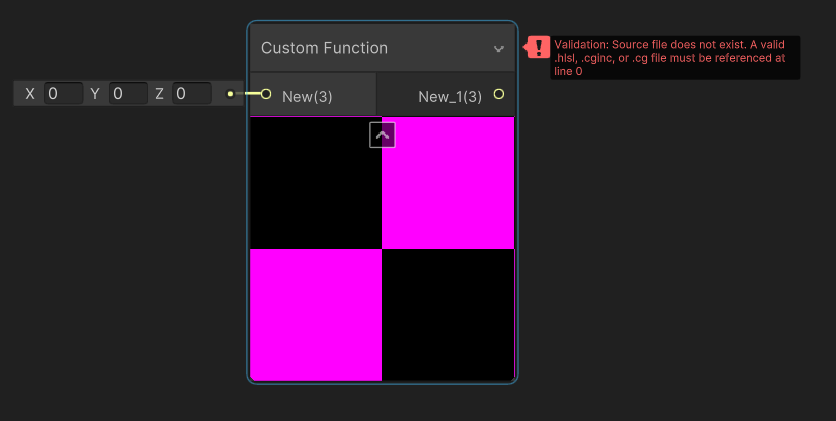
Not to my knowledge. Is it referencing a proper file ?
You could however re-create it's behaviour and expose all the settings you need.
Do these things relate to having the Sample Buffer node in place? 🤔
I don't think so.
so we do have a node, but if I want to expose it's parameters I should write my own hm
I looked at the generated code it gave, it does have the floats, but I don't yet know how to utilize them 🤔
this is from the Channel Mixer node ^
Here is an easier way to find the generated code 🙂 https://docs.unity3d.com/Packages/com.unity.shadergraph@13.1/manual/Channel-Mixer-Node.html?q=channel mixe
true 😅
And the 9 floats OutXinX are the weights
about generated code example: the heck is this block of code doing? https://docs.unity3d.com/Packages/com.unity.shadergraph@6.9/manual/Rotate-Node.html?q=rotate. is there some black magic reason behind that because even if rMatrix is a matrix and not a float, that doesn't make much sense for me. Even the generated code from actual shader graph has that

Also it doesn't have anything in the console when it gives the error, so I can't trace it
My thought about this, is that maybe, I could edit the channel mixer nodes code, to expose the parameters
should be just a few lines
That is weird. It looks like it's remapping the values, but then it undoes it. It's possible that the compiler will optimize this out.
even if compiler is mart, i kinda doubt it's that smart
I've pinged the devs, it could be an old code shenanigan
how do I do that? I was trying to do something with lerps, but it would be really nice to have the channel mixer functionality
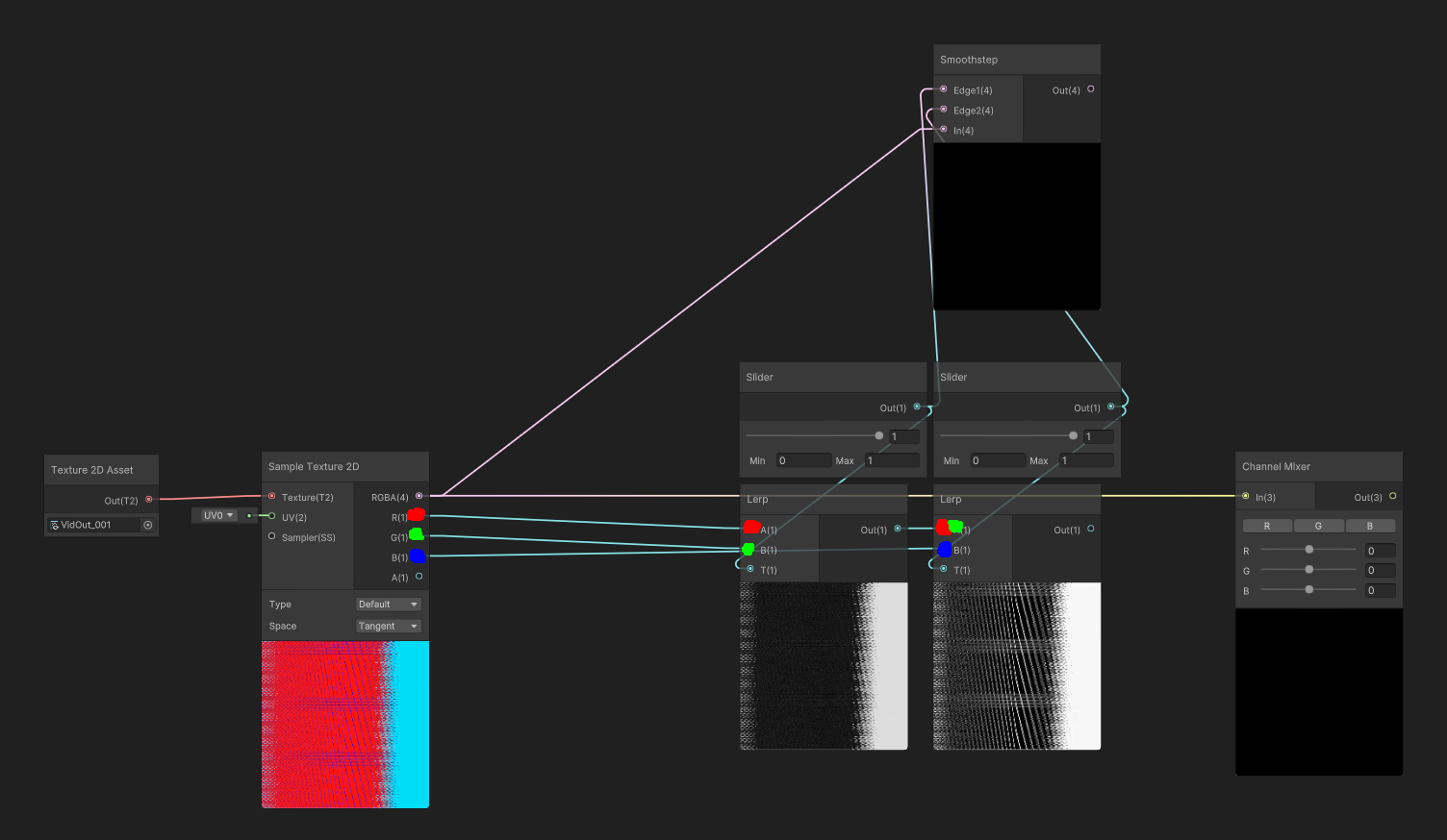
ignore the smoothstep node
Lerps is not how the channel mixer works.
You have to redo in shadergraph what the code is doing.
Or you could copy the code to a custom function and expose the parameters
the second option seems easier xD
so what's the thing with the custom function node?
IDK, I mean, it should just work 🙂
It's not immediately working when you create the node because it needs setup
Does anybody know anything about GetStereoProjectionMatrix and GetStereoViewMatrix in VR? I'm always getting the identity matrix, does that make sense?
                    var proj = camera.projectionMatrix;
                    var view = camera.worldToCameraMatrix;
                    var viewProj = proj * view; // Not identity matrix!

                    Matrix4x4 viewProjLeft = Matrix4x4.zero;
                    Matrix4x4 viewProjRight = Matrix4x4.zero;
                    if (renderingData.cameraData.xrRendering) {
                        Debug.Log("Camera stereo");
                        var projLeft = camera.GetStereoProjectionMatrix(Camera.StereoscopicEye.Left);
                        var viewLeft = camera.GetStereoViewMatrix(Camera.StereoscopicEye.Left);
                        viewProjLeft = projLeft * viewLeft;
                        Debug.Log($"viewProjLeft: {viewProjLeft}"); // identity matrix!

                        var projRight = camera.GetStereoProjectionMatrix(Camera.StereoscopicEye.Right);
                        var viewRight = camera.GetStereoViewMatrix(Camera.StereoscopicEye.Right);
                        viewProjRight = projRight * viewRight;
                        Debug.Log($"viewProjRight: {viewProjRight}"); // identity matrix!
                    }
camera.stereoEnabled is also always false... so desperate hehehe
For distortion/wind on foliage I usually just use a sine based on the worldspace position, e.g. https://www.cyanilux.com/tutorials/soft-foliage-shader-breakdown/#wind
But noise also works as long as you can map it to the geometry without seams. If two connected quads are mapped to completely different parts of a texture for example, that creates a seam in the UV coordinates so the noise generated also has seams.
Currently you're using the Position node as the uvs for the noise so it shouldn't be producing seams though. It's hard to tell just from the graph where the problem lies. While debugging it's usually useful to output values to the fragment color/emission so you can see how it applies to the model and you should be able to see the seams (where values change abruptly)
Hey can anyone guide me through how to make a normal map scroll in unity? I have been searchig for the last 2 hours
Also I am using unity shader graph (URP)
Unity seems to do the same for the HDCamera:
from https://github.com/Unity-Technologies/FPSSample/blob/master/Packages/com.unity.render-pipelines.high-definition/Runtime/RenderPipeline/Camera/HDCamera.cs
           if (camera.stereoEnabled)
            {
                textureWidthScaling = new Vector4(2.0f, 0.5f, 0.0f, 0.0f);
                for (uint eyeIndex = 0; eyeIndex < 2; eyeIndex++)
                {
                    // For VR, TAA proj matrices don't need to be jittered
                    var currProjStereo = camera.GetStereoProjectionMatrix((Camera.StereoscopicEye)eyeIndex);
                    var gpuCurrProjStereo = GL.GetGPUProjectionMatrix(currProjStereo, true);
                    var gpuCurrViewStereo = camera.GetStereoViewMatrix((Camera.StereoscopicEye)eyeIndex);

GitHub
A first person multiplayer shooter example project in Unity - FPSSample/HDCamera.cs at master · Unity-Technologies/FPSSample
but I get always false and identity matrices 🙂
Use a Tiling And Offset node in the UV port on the texture sample, with Time node in the Offset. e.g. this is just a noise texture but same thing to make it scroll. Would change Type on the texture sample to Normal for a normal map. Can change the inputs on the Vector2 node to change the direction it scrolls in.

Ok thanks also how do I convert it back to normal cause I did try a part this method but it just didn't convert back to normal
It just treats it as a texture after this and doesn't let me input it into normal slot
You want to put it into the Normal (Tangent) port in the Fragment block, not the Vertex stage Normal.
Unless you really do want per-vertex normals, in which case use a Sample Texture 2D LOD node.
Oh my god I am stupid Thank you for the help
Really appreciated, thank you
I'm trying to convert glsl code to hlsl but i'm not getting the same result, and I think i maybe know the code where the problem comes from.
Can you guys confirm if this in glsl:
mat4 calcRotateMat4X(float radian) {
    return mat4(
        1.0, 0.0, 0.0, 0.0,
        0.0, cos(radian), -sin(radian), 0.0,
        0.0, sin(radian), cos(radian), 0.0,
        0.0, 0.0, 0.0, 1.0
    );
}

mat4 calcRotateMat4Y(float radian) {
    return mat4(
        cos(radian), 0.0, sin(radian), 0.0,
        0.0, 1.0, 0.0, 0.0,
        -sin(radian), 0.0, cos(radian), 0.0,
        0.0, 0.0, 0.0, 1.0
    );
}

mat4 calcRotateMat4Z(float radian) {
    return mat4(
        cos(radian), -sin(radian), 0.0, 0.0,
        sin(radian), cos(radian), 0.0, 0.0,
        0.0, 0.0, 1.0, 0.0,
        0.0, 0.0, 0.0, 1.0
    );
}

mat4 calcRotateMat4(vec3 radian) {
    return calcRotateMat4X(radian.x) * calcRotateMat4Y(radian.y) * calcRotateMat4Z(radian.z);
}
is the same as this in hlsl:
float4x4 calcRotateMat4X(float radian) {
    return float4x4(
        1.0, 0.0, 0.0, 0.0,
        0.0, cos(radian), -sin(radian), 0.0,
        0.0, sin(radian), cos(radian), 0.0,
        0.0, 0.0, 0.0, 1.0
    );
}

float4x4 calcRotateMat4Y(float radian) {
    return float4x4(
        cos(radian), 0.0, sin(radian), 0.0,
        0.0, 1.0, 0.0, 0.0,
        -sin(radian), 0.0, cos(radian), 0.0,
        0.0, 0.0, 0.0, 1.0
    );
}

float4x4 calcRotateMat4Z(float radian) {
    return float4x4(
        cos(radian), -sin(radian), 0.0, 0.0,
        sin(radian), cos(radian), 0.0, 0.0,
        0.0, 0.0, 1.0, 0.0,
        0.0, 0.0, 0.0, 1.0
    );
}

float4x4 calcRotateMat4(float3 radian) {
    return mul(mul(calcRotateMat4Y(radian.y), calcRotateMat4Z(radian.z)), calcRotateMat4X(radian.x));
}
The order of the matrix multiplication in hlsl doesn't look like it matches. Maybe try return mul(calcRotateMat4X(radian.x), mul(calcRotateMat4Y(radian.y), calcRotateMat4Z(radian.z))); ?
I think i actually tried all 9 combination and none was right
wait a second because i have another part of my code that i'm not sure about
glsl
    float yaw1 = atan(dir1.z, dir1.x);
    float pitch1 = atan(sqrt(dir1.z * dir1.z + dir1.x * dir1.x), dir1.y) + PI;

    float yaw2 = atan(dir2.z, dir2.x);
    float pitch2 = atan(sqrt(dir2.z * dir2.z + dir2.x * dir2.x), dir2.y) + PI;

    mat4 rot_node = calcRotateMat4(vec3(0.0, yaw1, pitch1));
    mat4 rot_parent = calcRotateMat4(vec3(0.0, yaw2, pitch2));
    ...
hlsl
  float yaw1 = atan2(dir1.x, dir1.z);
  float pitch1 = atan2(dir1.y, sqrt(dir1.z*dir1.z + dir1.x*dir1.x)) + PI;

  float yaw2 = atan2(dir2.x, dir2.z);
  float pitch2 = atan2(dir2.y, sqrt(dir2.z*dir2.z + dir2.x*dir2.x)) + PI;

  float4x4 rot_node = calcRotateMat4(float3(0.0, yaw1, pitch1));
  float4x4 rot_parent = calcRotateMat4(float3(0.0, yaw2, pitch2));
  ...
I know the atan2 arguments in hlsl are reversed
And i think i got it right but it's really the only thing where there could be a bug looking at the result
It's not very helpful, I can't even tell if this code is hlsl, or shaderlab.. if I don't know the languages.
And I don't xD
how can I use this in a custom function node?
it doesn't even tell you what code does the node accept
It uses HLSL, There's a docs page that explains how to use the Custom Function node : https://docs.unity3d.com/Packages/com.unity.shadergraph@13.1/manual/Custom-Function-Node.html
hey all, I have a plane and I have objects moving on top of it. I'd like to make it glow around the units. I
I achieved that by creating a 6x6 texture(I have a max of 36 units), packing the position data and radius inside of each pixel and then my shadergraph has a custom function node that iterates through the pixels and determines the glow strength based on the distance.
It gets the desired results but performs very poorly. Is there a less expensive technique I could use?
I just have one quick question about shaders, I think this looks pretty good, but I want anything outside of the lines to be transparent, how can I do that?

please @ me if you know
the white ones, but I figured it out
if i made a decently complex shader in Amplify shader engine, with rim light, 2 types of emission, bunch of panning and fx, orientation, etc... and i put this on a plane, and then made a plane prefab and used that plane for tiles in a game, would that have a significant impact. what about just one time for a main character etc? I see alot of talk about draws and shaders and etc and didn't know if prefabs change things or not or what are things to avoid, like... the tile floor question i asked
!ban 285373952757465088 scam
 Coco.#3656 was banned

Maybe you could multiply the color by some value (like 1.5) to get more intensity and use bloom effect to make it look brigther. (You have to enable hdr)
how can I do this, (i'm new to shader graphs)
What part?
multiply
Multiply node 😄
Multiply the color you put to base color (or whatever its called nowadays) slot by (1.3, 1.3, 1.3) (or something similiar) and then put that result in base color slot
Hey peoples, tag me in the reply please. I have a custom shader im trying to add a hue shift toggle to the shader to influence rim color on a material. Is anyone versed enough in shader coding that can help add just that functionality ? Any help is greatly appreciated! I can send you the shader file if needed. I got the check boxes and hue shift slider into the unity editor where I can see it but the buttons and slider do not work. This shit is hard yo. Can someone help me please!


Everything after rim color does not currently work

Would assume there's currently some negative values since white - red = cyan. It looks like you need to use a Saturate node (clamps between 0 and 1) on the colour (and/or alpha perhaps)
can i send my shader here and have you add it? since i dont really know what im doing