#archived-shaders
1 messages · Page 230 of 1
but for some reason this is just accessing the parent, anyone know why?
nvm i fixed it
i want to get into shaders, should i focus on using Shader graph or should i learn HLSL ?
I'm not sure where to put this, but I want to procedurally generate an 8 x 8 sprite as a paint splash when I attack in a game
is it possible to make a sprite in Unity from nothing?
it sounds graphics heavy
I managed to get it to work, mostly. It seems like Depth Normals kind of wipes away the AO, if I turn up Direct Lighting Strength I can see the halo effect happening but no AO. If I keep it to depth and crank up the Direct Lighting Strength and play with intensity I get AO, but that behaviour seems a bit odd compared to how a lambert shader reacts to it.
I'm not exactly sure why this happens, I tried having the aoFactor directly change the colour of the models instead of the lighting but the results were the same. So maybe it's my DepthNormals/DepthOnly passes?
I have a very basic transparent cutout shader set up but when applied to the mesh blending is bad, any idea what might fix it

also I have tried the other blend modes with no success :(
the same shader is used underneath the hair cards which does render fine though
oh and also this is not using shadergraph

Hey, I was wondering if anyone could point me into the right direction in regards to a specific effect I'm trying to get with a shader.
Basically, what I'm trying to do is a vertex displacement shader where it's similar to a flag, but both sides of it are attached to a pole.
So only the center of the object will move in and out, with both sides staying as is
I already am aware I need to use the UV value to accomplish this, but I'm not entirely sure how to manipulate the value in order to change the 0->1 value become a 0->1->0 value
For example you can remap it to be between 0 and pi (multiply by pi) and take sine of that number.
Alright I'll give this a shot, thank you
Np, you could also try parabola instead of sine function because it would look pretty much same and it would be cheaper
Alright thanks for the help, it works perfectly
the difference between parabola and sine is quite small as you see. if the value between 0 and 1 is x, then the parabola formula is -4*x*x+4*x

True, I learnt about this in math class but it's been awhile lol
math is super useful on shader programming
Programming in general even
I'm using the parabola method now, thanks for the help aleksi!
Hi! I need to change sampler dynamicly based on mip map level. Right now I am sampling the texture twice and then choosing the result. Is it possible to make it more efficient? I cannot just choose sampler argument dynamicly, because it should be literal expression...
branching call to SAMPLE_TEXTURE2D doesn't make it run faster 😦
Having an issue with this lava material. For some reason there's a delay between hitting play and the material "appearing"

I guess Cells outputs the same colour if the angle is 0 (and time starts at 0). Could use an Add node to offset the value before the Angle Offset port.
Might be the DepthNormals/DepthOnly passes. Hard to say without seeing the code. It's usually best to compare your code directly to the URP shaders (like URP/Lit or SimpleLit). https://github.com/Unity-Technologies/Graphics/tree/2021.2.8f1.4208/com.unity.render-pipelines.universal/Shaders (may want to change branch/tag to version you're on too)
That worked perfectly thank you Cyan! I assumed it was to do with the Voronoi position at runtime but I'm pretty new to Shader Graph so had no idea how to offset it

I'd say it mostly depends on the pipeline.
Shader Graph only supports Built-in RP in 2021.2 (and I think may still have bugs) but otherwise you need to use shader code (CG), but there's plenty of tutorials out there.
For HDRP you definitely just want to stick with Shader Graph as writing shader code for that is very undocumented and probably not recommended.
For URP, either is okay. There's also no reason why you can't learn both, as some of the knowledge will still translate between graph and code form. Personally I'd start with Shader Graph as it does a lot of the setup automatically for you which can be nice. And if large graphs isn't your thing, you can still also write HLSL code in a Custom Function node. For fully code-written URP shaders I've also got an article going through most of the basics : https://www.cyanilux.com/tutorials/urp-shader-code/
If it's for a sphere mesh maybe you want to use Scene Depth? As well as depth to the fragment which would be Position node in View space, Split and Negate the Z/B axis.
Or if it's still for the skybox method, or as an image effect / blit, maybe could use a ray-sphere intersection function. I've used the first function here before : https://iquilezles.org/www/articles/spherefunctions/spherefunctions.htm (maybe the second will also be useful for your use case). Can use a Custom Function node but it's GLSL not HLSL so you'll need to convert it (mostly just vec3 -> float3).
It's not really a tutorial (and not in Shader Graph) but Sebastian Lague did a video making an atmosphere (the first few minutes might be something similar to a "quick and dirty" example but later parts are more complicated) : https://www.youtube.com/watch?v=DxfEbulyFcY (They also share the project files in the description if you want to look, but bear in mind if you use that it's under the MIT License)
Probably will want to look at the Texture2D class. https://docs.unity3d.com/ScriptReference/Texture2D.html Something as small as 8x8 might not that be expensive. Sprite also has a constructor which takes the Texture2D if using a Sprite is necessary (rather than a textured quad).
You could also just have a bunch of predetermined splash textures (in like a sprite sheet/atlas) that you switch between to add variation.
Anyone have an idea?
Thanks, I'll take a look at it. Appreciate the link.
For clarification, "change sampler dynamically" ....per triangle/vertex or per pixel?
per pixel!
Oy, was afraid you'd say that.
I actually managed to do what I want using SAMPLE_TEXTURE2D_GRAD 🙂
I sample once using it, with bilinear filter
but! I emulate point filtering by rounding the uvs
so for my case it was enough (i want point for lod0, and biliner for other lods)
and I am using textureGrad because it has anisotropic filter
i couldn't just use SAMPLE_TEXTURE2D because for some reason it has artifacts when I am rounding the uvs for bilinear to behave like point
Hey thanks! That's some good point,i mainly stick with hdrp on 2021 lts. I'll start with the graph, wich i guess will also prepare me for vfx graph. But learning both can be an asset indeed
hello, i'm having trouble moving my first graph shader from the 2D URP to my game. using the file gotten from "View Generated Shader" (GeneratedFromGraph-Name.shader) gives me errors (example: "Shader error in 'Solid': Couldn't open include file 'Packages/com.unity.render-pipelines.core/ShaderLibrary/Color.hlsl'. at line 79"). trying to use it anyways gives warning messages (Could not create a custom UI for the shader...). how is this supposed to work?
Looking for some help, a shader I created in the shadergraph for some reason is flickering and causing artifacts when run on a mac webgl build, but otherwise its fine in the windows webgl builds

At the top you can see parts of it, but while moving the flickering is pretty intense
If someone can help me with the above let me know


I guess with flat normals? Don't know really. Please also phrase your questions to everyone and don't ping me specifically
ok, sorry about that
my problem is i thought the same thing but dlat shadiong didnt work
i think so
you can use either fresnel or dot product between normal and the ray coming from surface to camera
Do you want them all to act as one object (each face = all at once) or each polygon to act individually (each face independent)?
i am trying to do a transparent effect with a grab pass but its also applied to objects in fount of the object. im using tex2Dproj(_CameraDepthTexture, pos) and COMPUTE_DEPTH_01 but they don't compare well, are they in different ranges or something
Output the results of each as a color and then use a color picker and see what values you're getting.
I can tell you that depth values are encoded and must be decoded.
when I create a blank shader graph there isn't a master node and I can't seem to add one, did they change this in an update or something? haven't used unity in a while
wait nevermind it's because I selected 3D instead of URP when creating the project 😦
okay what? I installed Universal RP on my unity project and whenever I create a shader graph, just a standard shader, the preview is always pink
@mental palm sounds like you don't have SRP asset assigned, would recommend starting from here https://docs.unity3d.com/Packages/com.unity.render-pipelines.universal@latest/index.html?subfolder=/manual/InstallingAndConfiguringURP.html
okay so I just made a new project and installed shadergraph and it's doing the same thing
is this a bug? or do I need to import other assets from the manager or something
the active targets list is blank....
that's so weird because my older projects literally have Built-In as an option by default
very strange
ah so upgrading my project version from 2020 to 2021 fixed it
lol idk
your shader graph target must match with the renderer you use
if using 2021.2 "fixed" it, you are probably using built-in target on SG then since it was introduced on 2021.2
if Universal target gives you pink preview, it typically just means you installed Univeral RP package but didn't actually enable URP itself
which you would do by assigning that mentioned SRP asset (there are step by step instructions on that doc page I linked)
so... no bug here
how can I open up the shader graph inspector? is there a hotkey or some preference I need to tick on?
nvm i have an older version installed
Any idea how/if i can grab the position of the Object casting the shadow in shader graph? I have a texture applied to the shadows an object receives and would like to offset that texture with the position of the shadow casting object

hi i have a problem with a shader
i'm trying to get some interactive grass to work with my game
but someone the grass is not rendering how it should
i get this error : ```cs
Shader error in 'Custom/GeometryGrass': 'GetAdditionalLight': no matching 3 parameter function at line 290 (on d3d11)
Compiling Fragment program
Platform defines: UNITY_ENABLE_REFLECTION_BUFFERS UNITY_USE_DITHER_MASK_FOR_ALPHABLENDED_SHADOWS UNITY_PBS_USE_BRDF1 UNITY_SPECCUBE_BOX_PROJECTION UNITY_SPECCUBE_BLENDING UNITY_ENABLE_DETAIL_NORMALMAP SHADER_API_DESKTOP UNITY_LIGHT_PROBE_PROXY_VOLUME UNITY_LIGHTMAP_FULL_HDR

no colors , it looks transparent
the line that causes the problem is this one i think : ```cs
Light light = GetAdditionalLight(j, i.worldPos, half4(1, 1, 1, 1));
If you're on older versions of URP remove the third parameter. Otherwise update to at least v10 (Unity 2020.2)
ohhhh thank you !
I’d love to add realtime changing fractals to a scene in unity, I heard a good way to achieve this is ray-marching, would it be possible to calculate the ray-marching render on a layer and then combine that information with the rest of the layers that use rasterization? Kinda like combining depth layers and renders
Aka, one layer uses ray-marching, and calculates the depth map and colors, and the other layers use the standard rasterization to do the same thing, and the camera combines the information into one image that it shows to the player
For example, Sebastian Lague made a wonderful ray-marching project in unity (source-files https://github.com/SebLague/Ray-Marching) and I think it could be fun to add the fractal he made to a vr game scene, but everything in that vr game relies on rasterization as the rendering method
I know it’s possible to combine two sets of rendering data into one image, but I have no idea where to begin
I managed to combine the cameras, but the depth fields aren't playing nicely
It's always just one on top of the other reguardless of position in the scene
i removed the last parameter, now the error is gone but i still have no color on the grass, do you have any idea why?
I think I know the problem, I don't think sebastian legues code generates a depth map
it just renders
hello i need help because my shader is not working
nothing is appearing on screen basically
i'm not sure why but it might be because it can't adapt to the current URP
i get this ```cs
Grass material was not upgraded. There's no upgrader to convert Custom/GeometryGrass shader to selected pipeline
UnityEditor.Rendering.Universal.UniversalRenderPipelineMaterialUpgrader:UpgradeProjectMaterials () (at Library/PackageCache/com.unity.render-pipelines.universal@10.7.0/Editor/UniversalRenderPipelineMaterialUpgrader.cs:25)
i found that actually the grass casts shadows but the mesh it self is invisible for some reason
Hey, have a quick question: Is it possible in shadergraph to combine 2 previously made shaders via a lerp? I'm new to shadergraph itself but have worked with node based shader graphs before. Let's say for instance I have a glowy moss material i used on Mesh A, and a rock material I use on Mesh B. these are fine being separate. Now I want to have glowy moss and rock on the same mesh lerped via normal. is it possible to somehow just "zip" material A and B up and have them as separate nodes for the 3rd shader where they need to be combined? I thought maybe I could do it with sub-graphs but it wasn't immediately apparent how... sorry, still new to Unity's shadergraph.
Can someone show me an example of just a very simple blend shader in shader graph?
I'm trying to learn the basics but don't really know where to start
https://www.youtube.com/watch?v=O75iGGUQXBI&list=PLpPd_BKEUoYjcFaqriaMchx5gOqBs2tDh this playlist is super useful

Unity Shader Graph - Introduction / Scroll Shader Tutorial
Welcome to this new mini series about Shader Graph!
We are going to see how to set-up Shader Graph in Unity, so you can start creating your own shaders / effects. After that, we create a simple Scroll Shader with Procedurally Generated Normal Maps.
Download a bunch of shaders in the ...
why does the alpha look weird on different angles? im trying to make a double sided shader with lots of transparency and it just goes blue on one side


The short answer is you can't, not without modifying the shadow casting in some way. The shadow texture that gets produced is like a depth texture seen from the light. It can see the depth in the scene, but doesn't have a way to determine which object is causing that depth (and hence casting the shadow).
If you absolutely had to do this, the modification you could make is to render a separate pass for all shadow casting objects into a second buffer, using the same projection matrix as the shadow map, which would store the world positions of those objects. You could then sample that texture later when applying your shadows to find the position of the object nearest to the light source that produced that shadow. However, it still won't work for all cases (e.g., multiple objects with overlapping shadows). Honest opinion is that it probably isn't worth the time. If you have a simple scene and simple geometry, and are looking to move the 'hatching' pattern with the shadow caster, consider using something like a decal projector instead
Not sure if this is the right area to ask, feel free to redirect me if there's somewhere better.
I'm looking to change the color of certain parts of a character, the project I work on uses atlas mapping so I was curious if I could create some shader / script / material that could move certain sections of the UV map to a different location on the master texture we use? If not is there a way to change the color of one area of the texture specifically?
I want to get a variety of colors for some armor sets but don't want to have to have 5 different meshes with different uvs, or have them split into different parts, we can't use saturation because it'd change the whole texture.
Thanks in advance.
Alright, thank you very much
I assume I need to post this in here. I'm making a game where you "attack" with a paintbrush and I want to paint on objects. I've googled it and I don't know exactly how to search to get what I want, I haven't found what I'm looking for.
I have a boxcollider2D on the paintbrush and a polygon collider on the house and I have these random 8x8 "splash" sprites, how do I apply them onto the building where I attack?
Is there a way to hide the faces that you wouldn't see if the shader was opaque when using transparency? I don't know the term for this, i guess its some kind of backface culling with the camera direction

I guess it would be some kind of occlusion culling inside a shader
You probably want to do a pass that only renders to the depth buffer before rendering your main one
Anyone an idea why the edges are red/yellow instead of transparent?


The Texture Visibility Length Group is what allows me to make my path transparent. (basically it is the current reason for the yellow/red color)
Instead of making it transparent it makes my edges colored
Might be some negative values resulting in the weird blending. Can use a Saturate node to clamp the value between 0 and 1 before putting it into the Alpha.
the only color data comes from the color node which is in the color group. But can this be still the reason even when my transparent vaalues dont use any color? anyway i will try to clamp it
Oh wow, it actually did. thanks. didnt thought that clamping was the reason
There is still colour in the screen buffer (the grey from the skybox) before the object is rendered. So if it's subtracting the blue/cyan colours (due to negative alpha values), that would result in red/yellow.
Ah, okey. thanks for the explanation. Ill continue working then 😄
Is there a way to put a sprite on top of another sprite? I'm trying to paint these splotches on another sprite
Hi, this line keeps giving me "Unexpected directory" even though I've double checked and tried a bunch of paths/filenames
#include "Includes/CS_marching_cubes_tables.compute"
the shader that line is in is in the same folder as Includes
It WAS giving me an error in VS that the file couldn't be found, but since then that filepath doesn't give an error in VS. Only unity
It's also the only new line in the whole shader
The whole error is "Shader error in 'CS_marching_cubes': Unexpected directive '
' at kernel MarchingCubes"
This is the entire shader:
#pragma kernel MarchingCubes
#include "Includes/CS_marching_cubes_tables.compute"

RWTexture2D<float4> Result;

[numthreads(8,8,1)]
void MarchingCubes (uint3 id : SV_DispatchThreadID)
{

    Result[id.xy] = float4(id.x & id.y, (id.x & 15)/15.0, (id.y & 15)/15.0, 0.0);
}
I don't work with compute shaders but are you sure the include should be using a .compute file and not just a .hlsl (or .cginc)
And "CS_marching_cubes_tables.compute" is just data, do I need to do something special in the editor import settings?
Unless the current way is outdated, I'm following seblagues project structure and code
Has writing compute shaders changed since 2 years ago?
It's probably something else then
"CS_marching_cubes_tables.compute" is just data, a bunch of arrays. In the editor it imports and looks abnormal to me, like this:
i was following a vid on how to make water and it needed a shader called PRB graph which i dont find, how do i fix it

Import the Universal RP
from package manger? i already did that yet i still don't find the PRB
There's more to setting up URP than just installing the package (though Shader Graphs should be an option either way afaik so you might want to check it's installed properly too).
https://docs.unity3d.com/Packages/com.unity.render-pipelines.universal@10.8/manual/InstallURPIntoAProject.html
.compute is typically used for the actual compute shader so while it might still work it's probably trying to generate a compute shader asset. I'd change it to a .hlsl or .cginc file instead personally.
Also I had a look at SebLague's code and his includes has an extra / before the folder which might be important. e.g. #include "/Includes/MarchTables.compute"
I tried with and without the leading "/" and the one with gives me an error in VS Code
I'll try changing the extensions
Well... it's strange that includes changed in the last two years, .cginc worked I believe
I wonder why including .compute doesn't work anymore
I have a surface shader on a meshrenderer- is there some way to know where the meshrenderer's "center" is in the shader, in screen space? I thought that was Position in View mode but it seems to give me inconsistent results
You mention surface shader but also "Position in View mode" which sounds like you're talking about nodes / shader graph. Can you clarify which you're talking about?
I'm not experienced enough to explain using correct terminology, so I'll explain what I'm doing:
I'm using shader graph to make a surface shader which draws a render-texture onto an object - but ignoring the surface's shape, instead drawing the matching position from screen-space
I was hoping to find a way to figure out where the surface'd object is in that space so I can have the whole texture on the object, instead of using the whole screen as space for it, but still having it just blit onto that rectangle

the box is the texture I'm mapping to the surface in screen-space; I'm looking for a way to use more of the texture on the object, by centering and scaling it to the object's size on-screen
I think you're looking for something like this

oho, okay- "Object" is the node I wanted, and it contains Position; I was using the "Position" node and getting bad results

here's what I've got so far
shadergraph is confusing, but somehow the .shader format manages to be more illegible than Rust was when I first picked it up
Also to assist with some terminology, I'd avoid using the term "surface shader" when talking about shader graph, as that usually refers to a lit shader type currently only supported in the built-in render pipeline (e.g. https://docs.unity3d.com/Manual/SL-SurfaceShaderExamples.html).
And by "ignoring the surface's shape" I assume you mean "rather than using the model/mesh uvs"
interesting, I thought "Surface Shader" was the opposite of "full-screen shader"
Not sure if there's actually a name for it really. I guess just "shader for scene object/renderer".
Typically just saying "shader" assumes it's going to be on a renderer, unless specified otherwise (by words like image effect / full-screen / post process / blit)
Hello everyone! I've been trying to google this all day, not really sure how to apply this, or even how to look for how to do this, but I want to "paint" a sprite onto another

right now I just have it creating an object
when I use the paintbrush
but I want to apply the "paint splash" sprites onto the house sprite and I'm not sure how to do that, do I use a shader?
so the splashes won't be off the building like in the image
If the only issue that you're trying to fix is the sprites bleeding over the edge of the house, a simple fix would be to use the house as a sprite mask and have the splatters only appear while inside the mask.
I do have everything else done
Is it possible to have a node in shader graph that is conditional based on the active target. For example, we have an emission node that is only available in hdrp, and I would like to work around that node for urp.
I just made the way it is now as a way to illustrate what I want but how do I mask the splashes from going over the edges?'
Not sure how to mask everything outside the house
cool thanks
So I was thinking of some solutions to how I can prevent my characters hair from clipping through helmets, and I have at least two solutions in my head.
Either do some Z-testing magic to render the helmet over the hair (but it needs to prevent the back of the helmet from rendering over the front of the hair for instance) or to have a height value which the hair will not render above.
My first attempt at the second solution failed given that I did not UV map from top to bottom and instead filled in randomly. I spent hours texturing the facials so I would love to avoid having to remap the UVs and textures, so is there any way to use the object relative texcoords to selectively not render the hair above a certain relative height?
EDIT: Found out I could substitute the UV node with the position node and use that.
syntax question. can i assign structs in single line? right now i'm writing
Particle p;
p.pos = id.xy;
p.dir = vel;
and i want to write it like in C#
Particle p = new Particle() { pos = id.xy, dir = vel };
but dont know how
Make a constructor or use object initializer syntax https://docs.microsoft.com/en-us/dotnet/csharp/programming-guide/classes-and-structs/how-to-initialize-objects-by-using-an-object-initializer
Learn how to use object initializers to initialize type objects in C# without invoking a constructor. Use an object initializer to define an anonymous type.
wut? constructor for structs in hlsl? how you do that? https://docs.microsoft.com/en-us/windows/win32/direct3dhlsl/dx-graphics-hlsl-struct have zero info about that
Struct Type
I'm stupid and didn't realize what channel I'm in
Although yes I do believe there's such a thing because you can do like float3(x, y, z)
well i have zero clue how to make constructor for structs in hlsl. i tried C#-like constructor and expectedly got syntax error. it's not really matter but kinda curious.
gah. okay. global methods instead of constructors. i wonder if there overhead for that.
though 2012 year. maybe there was some improvements in 10 years :D
Could probably write a macro, e.g.
#define PARTICLE(name, a, b) Particle name;\
name.pos = a;\
name.dir = b;
(It's been a while since I wrote one so might have made a mistake (might need some #?) but should give general idea.)
Can then use with PARTICLE(p, id.xy, vel) on a line
oh yea. also macro. nice idea. though it kinda suck if i change struct cause i also need to change this macro but it will also work.
though i assumed there is more direct way to do it. kinda confusing that there is none it seems.
wait what. ComputeBuffer have set for name but not get? how do i get it's name?

Hey, does anyone know how the ground in this video is generated? Is it a texture or a shader/procedurally? https://www.reddit.com/r/Unity3D/comments/ck4su4/this_procedurallyanimated_robot_is_named_b0xe_hes/?utm_source=share&utm_medium=web2x&context=3
If it's a shader can someone tell me how to make something like this?
Thanks 😄

The ground just looks like a textured terrain
Hello i was playing around with shader graphs and seem to have lost my work somewhere along the line. I have the screenshot of the result though


How do i end getting the 2nd output from the first one?
The actual image looks like this by the way

Do you know if it is also possible to generate it procedurally?
Yes, you can generate a terrain mesh procedurally if you want, or even a terrain, but this is not only done with shaders, as it needs collisions
No not the terrain, just the "texture" that is on the terrain. With the grids.
Oh yes, this could totaly be done procedurally with shaders.
Take the XZ world position and pass it through some maths
I'm very new to Unity, is there maybe a video/guide that explains how I do this? Thanks!
Unless you really want to have this as a procedural grid that could change size/color/thickness/whatever, if you're new to shaders, and furthermore Unity in general, I'd recommand to just take the easy route and use a simple texture.
I understand this, but the point of it for me would be to learn how to do it with shaders 😄
Else, maybe just start learning shadergraph, Brackeys did nice introduction videos : https://www.youtube.com/watch?v=Ar9eIn4z6XE
● Check out Bolt: http://ludiq.io/bolt/download
The time has come... Let's explore Unity's new Shader Graph!
♥ Support Brackeys on Patreon: http://patreon.com/brackeys/
····················································································
♥ Subscribe: http://bit.ly/1kMekJV
● Website: http://brackeys.com/
● Facebook: https://f...
Hello, how I do increase the texture size of another asset in the shader graph?
Can you elaborate?
super simple question, im using shadergraph. Im trying to create a whale-hunting game but am having trouble figuring out how to get the point on the mesh where the whale is hit by a harpoon, ideally I'd like to work with the mesh itself rather than the texture of the mesh because I want to do some vertex displacement with the information
you can send that information to the shader using Material.SetVector (you also have to make a property for that) and the on vertex shader you can for example compare the distance to that position to make something
if the harpoon follows the whale, it would be good idea to send the hit position in local space and use Position node with local space enabled
@mental palm there may be some better ways to do that tho. you should probably give more details about the effect you're looking for so we could discuss about the different solutions to achieve that effect, shader is not always the easiest and best looking way (maybe not the most efficient either)
trying to do a ripple effect starting from the point of the hit across the surface of the mesh
I was planning to do just do some kind of vertex displacement using a noise texture of some kind that starts from that vector you described
In shader / shader graph I have a vector 1 / float variable that is configured as a slider between 35 - 280 however the ideal way I would want this slider to work is to be a value between 0 - 255 that when the slider is at 0 the value emitted is 280 and when the slider is at 255 the value emitted is 35. I believe I could use a custom function node for this possibly, but does anyone have any suggestions on how they would do this?
where is the pbr shader graph?

Use a Remap, or Inverse Lerp node
So thank you everyone for your help so far! I've got something working right now that looks good. I have a game where you paint on everything. Buildings, cars, people, etc. Right now I just have the buildings. What I use is a "paint splash" game object for each attack, and sprite masks. Now this is fine if there were just buildings.

Try under Shader -> HD Render Pipeline, probably called Lit instead.
This creates 2 problems. 1 - That's a lot of objects. and 2 - this won't work with moving/animated sprites. Is there a solution with shaders like a surface?
lit shader graph?
oh i found it thanks
Thank you, used remap, and it worked like a dream.
I assume it would work with moving sprites if you parent it to the object it's applied to.
But yeah, that's a lot of sprites. I don't typically work in 2D but could try looking into Graphics.DrawMeshInstanced (or Graphics.DrawMeshInstancedIndirect) rather than using sprites & gameobjects, (also with Stencil passes in the shader for the masking). Though using those you might still have the problem of being able to move them as updating positions might still be expensive. Separating it into two calls (static-only vs dynamic) should help.
An alternative might be to generate a Render Texture for each "paintable" object (preferably equal to it's size on screen) and Graphics.Blit to that texture with a shader that draws the paint splash centered at a given uv coord, and probably scaling based on the texture width/height.
Can then draw that texture either in the sprite's shader - or if that affects batching could also just render it onto a quad ontop of the regular sprite with sprite masks to mask it.
(No idea if these solutions are good or will even work, but might be something to look into)
What happened to Unity.ShaderGraph? Is there no way to create Shader Nodes using the CodeFunctionNode anymore?
For Unity 2019+ versions CodeFunctionNode is internal. There is a Custom Function node in the graph you can use to run custom hlsl code. https://docs.unity3d.com/Packages/com.unity.shadergraph@10.8/manual/Custom-Function-Node.html
(And if you want it to make it look like an actual custom node can put it in a Sub Graph)
Is that how ShaderGraph Essentials(https://assetstore.unity.com/packages/tools/particles-effects/shadergraph-essentials-141671) is done? I'd like to create ShaderGraph extensions for the Asset Store, or should I just join the band and create Amplify shader extentions?

Use the ShaderGraph Essentials tool for your next project. Find this and more particle & effect tools on the Unity Asset Store.
How do people actually achieve a performant mesh outline that looks good? The shaders/tutorials I've seen (and have been all through youtube, github and the assetstore) are all either extremely limited, look bad or only work in very specific scenarios. Are people doing it properly by baking the outline in each model texture instead?
I have no idea how it's implemented, but it works very nicely
This looks more an outline as a highlighter effect than the drawn toon kind though, or am I wrong?

This is essentially the kind I'm looking for. Is it a shader? Texture? Mix of both?
this looks like edge detection outline thing

Unity Forum
(Now updated to work up to 5.4.0f3)
As I was working on my project, I was looking into edge detecting and the current image effects edge detection...
Hello. I’m trying to achieve an effect where objects create “trails” by using the camera’s “Depth only” clear flag. However, this does not work for me in VR. I’m using single pass instanced stereo rendering and the effect only works in one eye and not the other. I’m able to reproduce the issue even with default cubes and standard materials. As you can see in the screenshot, right eye is working correctly, but left eye seems to be clearing no matter what. Is this fixable somehow? Is there a technical reason why this is happening? Is there a 2nd hidden camera that I need to propagate the clear flag to? Or is this a Unity bug? Any help or direction is appreciated, I found absolutely nothing about this searching online.

I did try outline detection but didn't have much success in URP. It always comes out looking like crap haha. I'll read that thread and try again. Thank you for pointing it out.
I'm trying to render-to-texture in single-pass-instanced mode- I have "XR Rendering" enabled on my camera, and Target Texture set to a double-wide RTT, but it only paints one picture onto it even when I'm in VR. Is there some flag I have to set to tell a camera to render XR-style beyond Output -> XR Rendering?
Does anyone know why this Shader Graph has this ugly white dotted artefacts inside the black line?
The preview doesn't have this and this is visible in the editor and in the game.
Using URP.


I'm trying to make an effect where there is an invisible "veil" which hides objects behind it, but once objects pass in front of it they are visible.
I went online and found that I might be looking for something called a "Depth Mask" so I went and found these resources:
https://web.archive.org/web/20210831213650/http://wiki.unity3d.com:80/index.php/DepthMask
https://github.com/doomlaser/DepthMask-Unity-Shader/blob/master/DepthMask.shader
The problem is when I create a material and put these shaders on it, then use the material on a plane with its visible face towards the camera, I get a gaping black plane which does not produce the desired effect.
I'm using URP so I suspect some of these solutions maybe outdated.
EDIT: the effect is similar to what this post describes on the Unity forum thread for a shadergraph squivalent: https://forum.unity.com/threads/depth-mask-shader-in-urp.855136/#post-5909156
Also explored Camera Stacking but I really don't think I have it yet.

Hello there I'm trying to make an UI Blur shader with Unity URP 2020, there are lots of solutions with CGPROGRAM but CG is not working with URP and I currently cannot convert the shader code to the HLSL completely right now. Is there any source or documentation that you can share about Canvas Blur if so I really aprriciate it. Thanks in advance.
Hello, say I have 2 shaders with 2 materials. One represents the mask and the other the masked object. How do I make sure the masked objects are drawn only on the mask object. Basically I would be changing the mask properties and would like all the masked shaders to respond accordingly
Probably want to look into Stencils. https://docs.unity3d.com/Manual/SL-Stencil.html
For URP in particular you can also override stencil values using the RenderObjects feature on the Foward/Universal Renderer asset which is useful as it can work with any material. You will still likely want to draw the mask with a stencil shader though.
@regal stag thank you, will look into it and write back
Can I design it in shader graph btw?
It seems to be shader code. Im playing around with Shader Graph
Shader Graph doesn't support stencils yet so you can't really use is for the mask object (but can still use it for the other objects to be masked as long as you then use the RenderObjects feature). If you also want that mask to be invisible you will want to use ColorMask 0 which also isn't something Shader Graph can do afaik.
@regal stag alright thanks alot for replying 🙂
@regal stag just another quick question. right now in shader graph, I scale the texture size using the vertex position but is there any way to scale the uv so that I can rather use that as a mask?

Scaling is just multiplying the coordinates by a value, so a Multiply node should work. Or use the Tiling input in a Tiling And Offset node (which is shorthand for uv * Tiling + Offset)
If you need to scale from center subtract 0.5, multiply, then add 0.5 back. e.g.

One easy way is to just blur the whole screen with the depth of field post processing.
If you need to only blur parts behind the UI then you'll probably need to look into and write a custom renderer feature to copy the camera buffer to an offscreen temporary render texture (via blit /draw fullscreen mesh), apply blur passes (e.g. Box blur, Gaussian) and then sample that as a global texture in the UI shader.
This might provide an example : https://alexanderameye.github.io/notes/scriptable-render-passes/, but you'll probably want to handle the second blur pass with an additional temporaryBuffer rather than blitting back to the colorBuffer (camera/screen).
@regal stag hello cyan, I was able to use the shader you had shared. It worked for textures with no alpha in the middle but for textures with alpha in between the image it displays a weird output. Do you mind if I share the results?
The skybox is rendered after opaques, so by writing an invisible object to the depth buffer the skybox is being clipped, hence the hole.
You could try rendering a shader that replicates the skybox to the quad. As long as it has ZWrite On should mask objects.
Or perhaps use alpha clipping in the shader used by objects you want to mask - would be similar to dissolve shader tutorials but based on space/position rather than time. (e.g. use the Position node (World), Split, take whichever axis the world is aligned to (RGB = XYZ), e.g. R/X axis and Step with the x-position of where the clipping plane should be. That can be used for the alpha, and the clip threshold can just be 0.5)
Sure, show a screenshot


The first one scales down properly
The 2nd one is scale 1 and when I scale down it cuts off at the face part of initial scale
These are sprites yes? Sprites typically generate a mesh shape from the texture to limit the amount of transparent overdraw. You can edit the sprite's "outline" though : https://docs.unity3d.com/Manual/SpriteOutlineEditor.html, or just set the sprite to "Full Rect" rather than Tight.
yea they are sprites
An alternative is to also just scale the sprite itself rather than the texture too
The Full Rect works :D. What I'm trying to do i morph say the first image to second image. I have 2 sprite renderers thats become full white and then I scale down the first texture and scale up the second texture
Kinda like the old Pokemon "evolve" white animation
where one shape slowly morphs into another over time
If they are separate sprites I'd still probably scale the sprite itself rather than the texture
@regal stag ok, will move it back to position. thank you
I tried doing replacement shaders, and they seemed to work fine, but when i built the game, one of them didnt work. Im new to unity and doing this as a project for school.
I tried to find the solution online and someone said that OnValidate() function doesnt work in build. How should i replace it so it would work?
Btw i did put them in always include shaders.# SOLVED
I feel really dumb right now but I didn't understand a thing on account of never having coded shaders.
I have a problem i have been having for 6 months on and off and i can;t seem to find a solid fix. Sometimes the shader graph results in a black result. I have this not often but it happen 1 in every builds. After openng the asset and saving it again, it seems to work, anyone has a clue why this bug is happening?:
black ground:

And the shader graph:

For the latter part of my answer I was referring to using something like this
(with Alpha Clipping enabled in the Graph Settings)
Can swap to a different axis if necessary. Or swap Edge/In to swap which side is clipped.

if someone knows this, you will be my hero for the day.. I keep having black grounds every 2-3 builds 😦 and i need to redo the whole assetbundle + build for iOS process. 😦 Extra info: seems when my friend who builds for Android builds the game, after I have black, when I build, he has 1 time black ground.
Does this account for any random renderer which is placed behind the depth mask shaded veil?
Shadergraph is a Godsend.
This method would be for the shader/material used on those objects. There is no depth mask here.
That won't work, unfortunately. I absolutely need those objects to be completely visible once they've crossed over. Adding logic for that on each object (in this case they're generated) doesn't seem like what I'd want.
Seems like an odd bug, I don't see anything that would cause this from the graph, unless it's related to the Color node put into Emission. If possible, I'd consider updating to a newer version of Unity or URP as this may be something that was fixed.
Mm @regal stag you might be very right
The emission seems to have some bug with it i think. When I use an attack in the game that has some light, it will show the colors of the ground.
Like when i fire a fireball, i see when it bounces some light on the ground (instead fo pitch black)
I always see some posts which solve the black hole problem by changing the render priority or camera flags (which is now replaced in favour of Camera stacking).
I tried camera stacking but it may not be the solution since I animate my main camera from a script which manages shaking and FoV tweens.
It uses the worldspace position so should be similar to what you want

what if i put in emission the "result" of the textures?
Also i can't really update 😦 i am on unity LTS 2019, so URP 7 for me
Okay, this should work.
As you can tell, I'm not at all well-versed with shader code. 😅 Shame me for being in gamedev for 3 years now.
However I am accessing the URP Lit shader properties for the objects, so does it mean I need to extend the default Lit shader?
@regal stag did this btw now, maybe it helps?

Unless you need everything the URP/Lit shader can do, can recreate the parts you need in Shader Graph. You can create properties in the Blackboard and the Lit Shader Graph has outputs very similar to the URP/Lit shader (like Base Color, Metallic, Smoothness, Emission, etc) so it'll probably mostly just be a few Sample Texture 2D nodes and Float/Color properties to connect up.
I'd assume that would basically just make the object unlit which probably isn't what you want
I just took the shorter way and extended the URP Lit shader.

I uh
need to know
how to make those darkened boxes bright I suppose
Under the Graph Inspector window (toggle with button in top right), Graph Settings, enable Alpha Clipping
Yuss.
While this is a Lit graph it still won't have the same inputs that the URP/Lit shader has unless you set those up too though.
Can create properties in the blackboard. Can (optionally) name them the same as what the URP/Lit shader uses (may have to look at the code to see the property names) so the values automatically switch over
They all have a reference. Should those be copied?
Well come to think of it I can edit all the static properties directly from the graph, and the ones I need to expose, I can expose!
Yeah
Except now I'll have to change the code which refers to the property inside C#?
Yea because you generate them procedurally right?
Think so.
Here's the code I use inside C#:
private static readonly int EmissionColor = Shader.PropertyToID("_EmissionColor");
...
BodyRenderer.enabled = true;
var material = BodyRenderer.material;
var pickedColor = colors.PickRandom();
material.color = pickedColor;
material.EnableKeyword("_EMISSION");
material.SetColor(EmissionColor, pickedColor);

Color.RGBToHSV(pickedColor, out var h, out var s, out _);
var pickedColor0V = Color.HSVToRGB(h, s, 0f);
Well as long as you use a Color property with the reference set to _EmissionColor it should still work the same
The EnableKeyword("_EMISSION"); part probably isn't needed for the graph material though
With this it kinda sounds like the black material is just super dark or not reacting to the ambient/main light but additional lights still illuminate it?
Since the Fragment shader variable doesn't really change, right?
So I don't need to expose Editor properties for those?
I'm not sure what you mean
Okay, this didn't work. The objects are now just transparent/don't show up.
This is how it's set up


In short, it's because you're using Nicest mode which uses fwidth (aka DDXY node), which compares the values of the uv input with neighbouring pixels (as fragment shader runs in 2x2 pixel groups).
Either use the Fastest mode, or if you still need the anti-aliasing (probably do if it's for a map this big) I think you could remove the Fraction node and use a Custom Function with your own version instead which uses the regular UV for usage with fwidth, but uses the frac(UV) for the rectangle calc. e.g. (untested though)
    UV = UV * 2.0 - 1.0;
    float2 w = float2(Width, Height);
    float2 f = min(fwidth(UV), 0.5f);
    float2 k = 1.0f / f;
    float2 o = saturate(0.5f + k * (w - abs(frac(UV))));
    o = min(o, k * w * 2.0f);
    Out = o.x * o.y;
This doesn't work either

I'm not sure which axis the plane is aligned to, but if you want the Z axis it'll be the B output instead of R.
Should do. You also need to drag the property into the graph and connect it to the master stack's Emission port though
Because R=X, G=Y, B=Z isn't it.
Primarily because a Color can be converted into a Vector4 afaik
Okay make that float4.
Yea
Okay so the effect works... but the direction's wrong 😂
Swapping the Edge and In ports will swap the direction
Or can use a One Minus node after it
Okay so is the step function that same step function which clamps values between two limits? returns 1 for the higher limit and 0 for the lower one?
One minus should work, then. Maths.
Shader code is approachable...
Should be able to hover over a node and press F1 for documentation on what each node does (or right-click and there's an option there). Step returns 1 if In is greater or equal to Edge, else returns 0. So yeah, One Minus makes sense to invert it.
Alright so while that piece of logic works and my objects don't feel like they're popping out of thin air all the time... the previous logic which recolours them isn't working.
Did you drag the Emission Color property into the Emission port
I suppose if you only need "emission" you could also swap the graph type to Unlit (and use base color port) instead too.
I'll expose some more properties since I think they absolutely need to be exposed.
Guess I won't be able to use material.color right?
Oh, I do need the base color.
Ah okay
Apparently it's mapped to _Color.
Alright, I have completed that bit of code.
Thank you for walking through this with me, even though this must have been an extremely simple exercise judging by the shader code.
I will return the favour by assisting some beginners in the programming channel, which I'm okay at. 😅
Happy to help 🙂
any time i create a new Material. it looks normal in editor but the moment i hit play it goes pink. but in runtime say i was to reset the material it looks normal again. its almost like it somehow looses the instance of the material on game load. this is in Unity editor/android
im quite at a loss its been like 3 days now
i am not using any render pipeline atm as well
just core rp
so i was able to determine anything Unity renders itself ie whatever my code doesn't interact with is whats pink
How to blend normals in shader graph which are in object/world space because Normal Blend node seems to absolute normals in Z direction?
Maybe Lerp? Not actually sure
Btw. Adding and normalizing them looks fine :3
Hello peeps, I wanted to extend the Lit shader in HDRP by changing the way it uses its AO map. I guess the naive approach would be to copy the entire Lit shader and change the lines im concerned with but is there a better way of doing this so that I'm not pinned to a specific version of the lit shader?
I'm looking to try to get rid of some of this "blurriness". I understand that the colored are simply interpolated between each vertex.
Is there some way to change that.
If you mean the interpolation, no. interpolation happens automatically and you cannot change that as far as im aware. Why you want to do the coloring in vertex shader? (And where you get those colors from)
I need most of these things to be auto generated. Can't do nice texturing for the most part. Also the data is coming in explicitly as Color -> Vector.
What color should the middle of a triangle that has red and blue and green verts be?
@steel notch
One way to pull off what you're asking is to generate the mesh and not share verts between polygons. Set all vert colors of one polygon the same.
You could then use the nointerpolation modifier on the struct member. https://docs.microsoft.com/en-us/windows/win32/direct3dhlsl/dx-graphics-hlsl-struct
Struct Type
Hello there, I am trying to learn shaders through the shader graph but I am really confused about the position node. What I'm trying to do is sort of a gradient, so I take the position node's red value. My intuition is that position values in the node preview go from [-1, 1] I want to make them go from [0, 1] so I add 1 [0, 2] and then multiply by 0.5 [0, 1] however the preview appears to go from a really bright gray to white. So how can I make this look like a black to white gradient? I know there's other nodes that can help with the gradient part, but I just want to transform the position coordinates and make them go from 0 to 1.

I believe the position values in the sphere previews are closer to the range of -0.5 to 0.5 iirc, but more importantly those values will vary depending on the mesh and space. You're using world space, meaning as the object moves around the scene/world the values will change.
BTW Its the same on all spaces except tangent
I thought that it might just be the node preview that was off, but if I preview on a plane it still starts on some value greater than 0
And it is the same even on all spaces except tangent space (on tangent it is all 0)
Tried assuming it is [-0.5, 0.5] it is better, but still off

Well as I said, it's closer to that but still not exact. But even if you could get it exact it's not important as the mesh you actually apply the material to will be different.
I don't think the preview is all that exact
The world coordinates will change anyway as soon as you move the object in your scene
Remap node is very useful if you need to squash or stretch ranges like that
@grizzled bolt @regal stag I was just testing how it looked on the different spaces when I took the picture, what I'll use is actually object space so I would assume previewing on a mesh should yield the desired result, but it doesn't
Here, I preview on view space to make it more obvious, but as you can see on the left the gradient is still off

Personally I avoid using the Main Preview. Saving the graph and previewing in the actual scene view is just far better.
Also unsure if it's actually off, or whether this is put into the alpha so the dark grey you're seeing might just be the background?
I think this thing is sentient and is doing it on purpose

Assuming it's the default cube mesh, it will have vertices at -0.5 to 0.5
oh
It would appear you were right

Thanks, will give it a try!
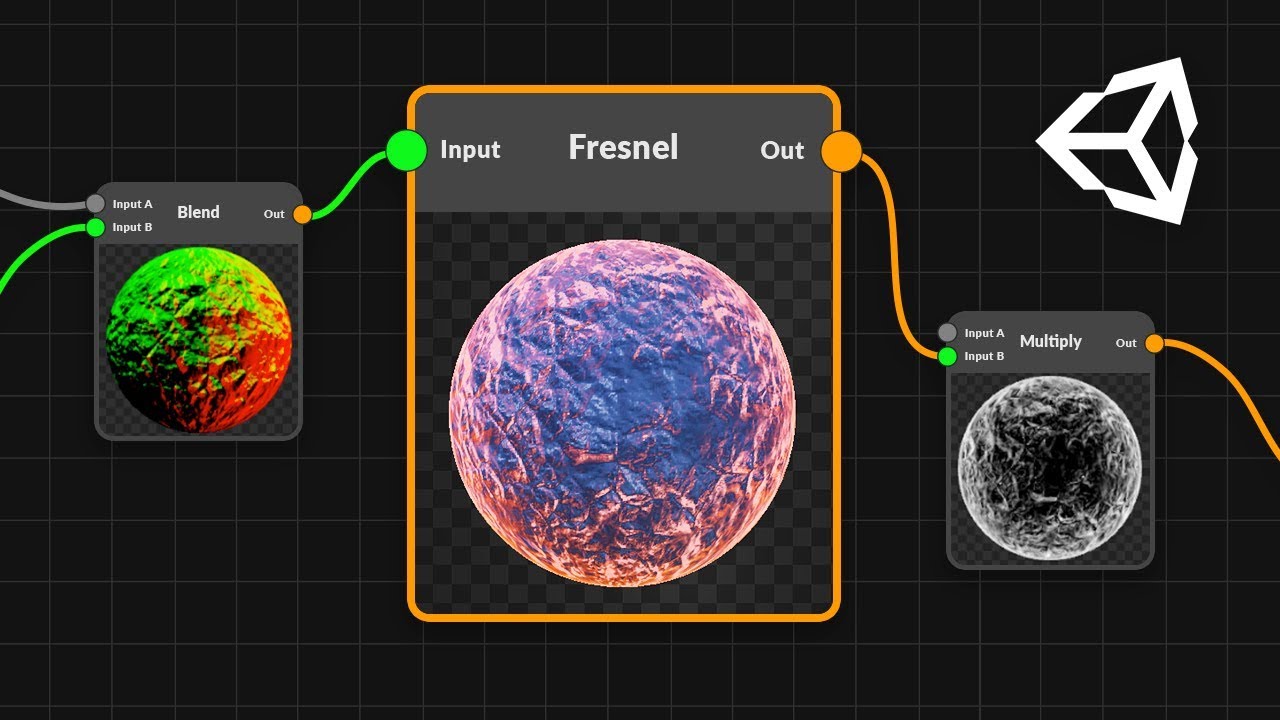
Good day, where should I plug the fresnel for it to overlap the alpha and outline the shield? It looks like the fresnel now covers just entire half of the shape

I am trying to use an array in hlsl but my output is always black. Can anybody tell me whats wrong with this?
const float4 debugColors[4] =
{
  float4(1,0,0,1),
  float4(0,1,0,1),
  float4(0,0,1,1),
  float4(1,1,0,1),
};
...
half4 frag (Varyings input) : SV_Target
{
  return debugColors[1];
}
nevermind I missed the "static" on the definition 😬
Heya folks! I need some help. How can I get the scale of any object in a 0 to 1 range?
At the moment, it is working on the sphere but not on the cylinder. But I want this 0 to 1 space for ALL objects. Both objects are in 1,1,1 scale

You can use a Remap or Inverse Lerp node on the G output but you'd still need to know the Min/Max coordinate of the mesh which isn't possible from the graph. Can either set that manually on separate material assets, or possibly loop through the vertices in C#, calculate the min/max and pass it to the material instance with material.SetVector (also using renderer.material to create material instance)
its a bummer but thanks for the answer..^^
Another option would be to store 0-1 coordinates in a second uv channel
@regal stag hello again cyan. i had a doubt. how do I convert transform position to texture object position in a shader graph?

Maintexture is the canvas
the offset is fed from the script
its the actual transform position
I tried using the Transform node but didnt wrap my head around how it works
this is how the actual image looks like with initial values

the secondary textures seem to be scaling along with the base texture
Sorry I don't understand the question
The red image is the base texture with 860x1876 sprite
in the shader i have 2 additional textures
one with size 529x805
and the other with 445x476
the 2 textures represent hair of a dummy
i parse its position vector from a svg file and and am to display it in the screenview
*I am able
but in shader graph I am unable to maintain the size(scale 1) and position of the image as in the screenview


This is how they look in the screenview
Okay well, for fixing the scaling... the Texel Size node should help with getting the sizes of each texture. I think you could then divide the MainTex's width & height by the width & height of the others to use as Tiling values when sampling them
As for the offset part though, I'm not really sure. I don't work in 2D a lot so struggling to get my head around it.
the scaling worked 😄 @regal stag thank you
I'm not very knowledgeable when it comes to shaders
and I was wondering if there is any way to upgrade a shader from the built in render pipeline to the urp one
I know it's heavily influenced by the methods it uses but still-
I would like some help with this
It may be easier to recreate the shader in Shader Graph, (though it depends what the shader does as some features aren't available in that, e.g. Stencil)
But if you do want to look into converting the code, these might help:
https://www.cyanilux.com/tutorials/urp-shader-code/
https://github.com/Cyanilux/URP_ShaderCodeTemplates
https://github.com/phi-lira/UniversalShaderExamples
https://gist.github.com/phi-lira/225cd7c5e8545be602dca4eb5ed111ba
Aight! I'll give it a look, thanks!
For the faces visible when facing camera it sounds like you basically want Fresnel Effect -> One Minus.
For double-sided you'd also need to use the Is Front Face & Branch to flip the normals for back faces.

so anyone knows how i can use a boolean on the emission to use it or not

a boolean for the selected part
anyone has any idea why this stretching in the middle is happening ?

that's a skybox btw
if i point the camera straight up, the center of the skybox is stretching like that
The skybox mesh has UVs that are actually 3D. The coordinates are the same as the Position node, but since most uv inputs expect a Vector2 it's only using the rg/xy components and stetches.
Can set the UV input manually to map the noise differently but that may depend on what you're using it for.
Some examples :
- Could use
UVnode,Splitand use R/X and B/Z components intoVector2but then it'll stretch at the sides instead. - https://jannikboysen.de/reaching-for-the-stars/#290b uses Arctangent2 & Arcsine
- https://www.patreon.com/posts/27402644 uses
i.worldPos.xz / i.worldPos.yfor "flat" clouds - I've also used this :

Can set up a Boolean Keyword in the Blackboard. As long as it ends in _ON it can be exposed (v12+ can expose any I think). Drag it into the graph and it'll have an On & Off input for which values to use when toggled. You'd probably want the output of your selected in the On, then just 0 in the Off. Don't overuse keywords though, as that may increase build times and materials with different enabled keywords will batch separately.
https://docs.unity3d.com/Packages/com.unity.shadergraph@12.1/manual/Keywords.html
Alternatively use a regular Boolean property and Branch node, but both sides will always be calculated.
thanks i used the branch and that one worked fine
@regal stag i tried the arctangent2 & arcsine method... this leaves a star shaped stretch right in the middle... then i tried your version which works perfectly except on the horizon which leaves this stretch :

Yeah, you won't really get a perfect mapping without any stretching. (For that you'd probably need more of a 3D noise function). With my version I hid most of the stretching as I only used the noise for the sky/clouds. Everything below y=0 was ground. I also always had clouds at the horizon and then faded the noise in based on y.
oh ok so basically just learn to live with whatever stretching fits best haha
got it
thank you 😄
Yeah, can also use multiple mappings and interpolate between them (kinda like triplanar mapping) but will be more expensive due to more texture samples (/ math in this case since it's generated noise)
thanks for the info... the tip of the 3d noise actually works without stretching too
Yeah, though 3d noise might look strange if you plan to offset it
haha indeed.. they look really weird... like going round (feels dumb saying it coz that's technically what they do IRL) but it looks very strange on a game
Hey Ive got a shader, I want that the object if part of it is under a certain height to be invisible. But I dont get it work right. any ideas how to do that?
If you're using Shader Graph it's basically just this (but with the G output rather than R)
#archived-shaders message
hey I've got a question that seems rather basic but the answer eludes me. I'm making a shader that generates patterns by using time and a tiling and offset uv and some noise. currenly I can make this pattern move in the x or y direction with the tiling offset, but is there a way to make my shader go from the center of the poly to the edges?
like radiating outwards from the center point
@regal stag Do you know where exactly I can integrate my Height Value then?
The height value would be in place of the Clip Pos property I used
You can use the Polar Coordinates node to go from a center point onwards in a circle-shape. It might also be possible to calculate coordinates to radiate outwards in a square shape though the exact function I'm not sure on.
But radiating outwards based on the vertices would probably require it just being UV mapped in a particular way. I don't think you'd be able to calculate it in the shader as each fragment has no information about where the edges are.
okay plugging the polar uv into my tile and offset did give a pretty good result. any ideas on how to hide the seam? its probably fine if I cant

If it's for noise, could find/make a noise texture which tiles seamlessly.
you can probably see it at the bottom
I dont have a noise texture I'm using gradient noise node
Probably won't be able to remove the seam then
oh well. thx anyways
Y'all know how in shader graph you sorta have overloads for nodes, like if it takes a vector you can put in floats and it works fine.
Is there any way to do that for custom nodes?
Or do you just throw in vector 4 and call it job done
Hey there, I need some help with learning about unity shaders. So far in every tutorial or official reference I've seen they seem to use a different function to return the vertices from the vertex shader. Some of the ones I've seen are UnityObjectToClipPos, GetVertexPositionInputs, TransformObjectToHClip, and more. Also some just multiply the vector by some unity constant (I asume constant given they names are in all caps) which I assume is the projection matrix.
Is there a good reference for these functions, the differences between them and when I might want to use one over the other.
When I apply the stock Image Effect Shader (With the colour invert removed) to a material on my sprite, it messes up the alpha or... Something I don't want happening. Any idea why and how to stop it?


Hello I am trying to render 2 sprites using one shader. The first one is the _MainTex which is the base and the 2nd one is another texture which sits on over the base. Image doing it with two sprites renderers.

The 2nd sprite which is the hair is a child of the base sprite renderer
now I record this transform vector of the child (its offset)
and would like to convert that in my shader graph

This is the shader with an offset of (0,0)
Basically how do i determine the offset to be fed to the material inorder for it to sit on top of the head
The first image has to be rendered in sprite renderer
*in one
hey, i'm writing a URP shader from scratch, and I need some functions from the package
but as soon as I do this:
i get an error:
redefinition of '_Time'
and the shader won't compile
this is my only include in the shader
How should I change the URP Surface Type option from C#?

You need to be using HLSLPROGRAM to include SRP library stuff, rather than CGPROGRAM which automatically includes some built-in shader stuff (e.g. UnityShaderVariables.cginc which contains _Time and other variables)
thank you Cyan, that indeed makes the error go away, but I now that I need to include UnityCG.cginc for further work, it won't let me
are there URP equivalents of UnityObjectToClipPos and such?
it has something to do with those huge Pack/UnpackVaryings and InitializeInputData functions, doesn't it
(looking at URPs SimpleLit)
All of these functions are basically applying the model-view-projection matrix to transform out of object space coordinates (vertex positions stored in the mesh) to positions in clip space for clipping. Which one you use depends on the render pipeline the shader is written for.
UnityObjectToClipPosis from the built-in pipeline includes (UnityShaderUtilities.cginc)TransformObjectToHClipis from SRP-code (SpaceTransforms.hlsl), so works in URP and HDRP.GetVertexPositionInputsis from URP (ShaderVariablesFunctions.hlsl) and is a shorthand way of obtaining the position in many different spaces. It returns a struct containing, e.g..positionWS(world),.positionVS(view),.positionCS(clip, same as these other functions),.positionNDC(normalised device coords, aka screen space, float4, requires doing xy/z in fragment). Compiler will ignore any you don't use.
These clip space functions end up doing :mul(UNITY_MATRIX_VP, mul(UNITY_MATRIX_M, float4(positionOS, 1.0)));, which would work in any pipeline (but it's usually easier to read a function instead of this). I think in built-in you might also see a single mul withUNITY_MATRIX_MVPwhich pre-combines the matrices though I think that's also slightly more expensive.
Oh that answer also works for you ^
yeah, reading through it, thank you 🙂
And yeah you don't want to include UnityCG.cginc for a URP shader. The ShaderLibrary will usually contain equivalent functions. (can look through https://github.com/Unity-Technologies/Graphics or the files in the Packages itself, but might be a little hard to find as the names don't usually match. I do have a few comparisons here : https://www.cyanilux.com/tutorials/urp-shader-code/#summary, that post also goes over writing shader code for URP if you haven't seen it already)
A few more links here might also be useful :
#archived-shaders message
wow, this is great
to be honest i was lost, writing a main lit shader for a hardware restricted game when you have no technical artist is... well, scary
thank you so much, i really appreciate it, it saves me a lot of hassle
Shader Graph doesn't really have proper UI support yet. It might still be possible but I don't know about HDRP.
Image Effect shaders are typically to apply effects to the whole screen. You probably just want the regular Unlit Shader template.
Either way the problem is the shader won't be set up to use transparency. It needs to specify a Blend mode, https://docs.unity3d.com/Manual/SL-Blend.html, (as well as output the alpha channel, if it isn't already)
Looking at the Default Sprite shader might also help :
https://github.com/TwoTailsGames/Unity-Built-in-Shaders/blob/master/DefaultResourcesExtra/Sprites-Default.shader
(also uses https://github.com/TwoTailsGames/Unity-Built-in-Shaders/blob/master/CGIncludes/UnitySprites.cginc)
The property it uses is _Surface, but it's a bit more complicated as that doesn't actually do anything to the shader, it's just for the material / shader GUI. Changing it also sets other properties (e.g. _SrcBlend, _DstBlend) keywords (e.g. _SURFACE_TYPE_TRANSPARENT, _ALPHAPREMULTIPLY_ON, _ALPHAMODULATE_ON), override tags on the material (RenderType), and possibly render queue (if not already overridden). See : https://github.com/Unity-Technologies/Graphics/blob/9931447cb89c17b9b833479e155a14ce003327b5/com.unity.render-pipelines.universal/Editor/ShaderGUI/BaseShaderGUI.cs#L599 (that's the master branch btw so may also want to switch to the tag for your version as it may be different)
I really just want to change the surface from transparent to opaque from script.
How can I get the pixel position of a fragment shader?
In terms of screen space? And for what pipeline?
If you're in built-in RP, use ComputeScreenPos on the clip space position in vertex shader, pass it through to fragment, divide xy by w component. That gives position in range of (0,0) being bottom left and (1,1) being top right. If you need actual pixel scales, multiply by the screen resolution (I think you can get that from _ScreenParams.xy).
Thank you 😄
Is there a discord for HLSL shader writing or Unity shaders in particular?
I can't find one on Google or Reddit
Wow thanks
Don't know of something that specific, this channel is the most official one. Some community members who share shader tutorials have their own discords too (but not going to advertise/link them here)
Gotcha. I'm having a problem when I upgrade this project to 2020. The includes stopped working and even after I fixed them one of the shaders has an error I can't find with stack trace

GitHub
Coding Adventure. Contribute to SebLague/Marching-Cubes development by creating an account on GitHub.
I'm gonna downgrade to 2019, but I figured I'd ask if someone has been through this before
Hello Everyone,
Does anyone know how to sample depth texture in single pass rendering for VR?
I'm trying to convert sabastian shader for VR I'm stuck at sampling depth.
https://github.com/SebLague/Clouds

GitHub
Cloud rendering test. Contribute to SebLague/Clouds development by creating an account on GitHub.
https://docs.unity3d.com/2017.4/Documentation/Manual/SinglePassInstancing.html
I have followed this to conver it into the single pass rendering.

For built-in RP? Looks like there are macros : UNITY_DECLARE_DEPTH_TEXTURE(_CameraDepthTexture) and SAMPLE_RAW_DEPTH_TEXTURE(_CameraDepthTexture, uv); which automatically switch between using sampler2D and Tex2DArray to support single pass instanced VR.
HI! I have posted this in the animation section but maybe it a question of shader. I am not sure.
I need to see a vein moving like a heart beating on an organic object. I did this animation with Blender using a vertex group and a modifier ( wave modifier). I can not import this in Unity as it is an internal thing of Blender. I wonder if some of you have ideas about how I can have the same result in Unity.
Yeah you could do some "vertex displacement" in the vertex shader for this. Probably offset along the vertex normal * sineTime, and using a texture to determine where the veins are to mask / control the strength of the offset. Would be cheaper than a skinned mesh animation too.
I came across a deformation effect in the asset store recently that has a ripple effect. It's a free asset, but have not had a chance to give it a go yet. Might be worth looking at if you have trouble with making your vertex shader.
@regal stag @spiral gust Thanks! I'll try all this. It will make my week-end! : )
Hi, is it possible to build an opaque shader with light translucency? 😄 I'm capturing an octahedron from within with a second camera. And I need to "see all light that falls on the octahedron from outside".
Hello can anyone tell me how I can fix my shader from turning pink. It looks fine in my shader graph but it turns pink when I make a material out of it.


Are you sure your render pipeline is set up correctly?
I am pretty new to this :c Could you please explain it to me?
What render pipeline are you using? (What template did you use to make the project)
The 3D sample scene (urp)
If you used urp template, its should be fine. Have you tried if any build in shaders work (just create lit material, not own shader graph)?
yea everything works except that
What unity version is that?
2019.4
Have you tried updating shader graph package or making new shader graph and see if it works?
I will try that!
Have you checked to make sure there is a render pipeline asset assigned under Project Settings?
But if all other materials work, cant that be the problem?
Depends what shaders the "other materials" are using. If they're using the Standard shader might just be in the built-in RP.
But if he made the project using urp template, id imagine it not being possible either
mhh so I opened a new project
the material isnt pink anymore but I cant assign the texture to it
I'm not convinced they used the urp template as they mentioned 3D and might just be confused about which pipeline that corresponds to. They also have a HDRP folder in their assets so it's quite a mess of different pipelines here atm
Is this both in the same shader?

Transparent shaders don't write to the depth buffer so can't easily sort faces
So is there a way to fix it or am I just SoL? if I have inside faces on a mesh thats transparent
Not sure. Could separate the interior parts into a separate submesh and render it with a different material with a lower render queue to force it to be rendered before the rest.
Or render a depth-only pass first so those faces can still be z-tested (basically just ZWrite On, ColorMask 0)
thanks @regal stag
I'm brand new to shaders & I'm trying to figure out the new shader graph but I see no issues here why isn't it rendering the gear icon in main preview?

Its pink because theres some error in the shader/render pipeline. Most likely the render pipeline isnt set up correctly
yeah I'm realizing that now
although now I got some really weird bug xDD


any clue why this happens?
You have to put the alpha into alpha block
Nowadays the Base Color contains only r, g and b components. You have to set the alpha separately
the alpha is set separately
From the A plot of the texture?

Drag the A from texture to that alpha block
Np
earlier it was the same but transparent for some reason
oh actually I probably got rid of the alpha channel & that happened*
I found the solution to it. I just had to press "save asset" which I didnt know... But thanks for your help to!
Would anyone know how I can read a texture atlas and draw only part of it to a part of my mesh?
Think a big texture file of tiles, read one of those tiles, and apply it to a tile on my mesh
this is surely an obvious one... but how do you get fresnel to work with the normal map?

I expanded the thickness for drastic effect
but I'm creating an outline that just copies the players alpha & offsets it in each direction up down left right then multiplies it by a color but for some reason, its inheriting the color of the original sprite & not the color node that I gave to it


Thanks to NVIDIA for sponsoring!
Learn more about NVIDIA Studio► https://nvda.ws/38AaA8K
Razer Blade Studio laptops► https://www.razer.com/studio
In this video we create outline effect using 2D Shader Graph!
● Learn more about 2D Shader Graph: https://youtu.be/5dzGj9k8Qy8
● 2D Glow Tutorial: https://youtu.be/WiDVoj5VQ4c
● Get Gothicvania Ch...
I'm following along with that tutorial

Anyone know how I can offset my UVs in a shader to be in the center of each tile?
I've tried programmatically setting the UV offset when generating the mesh but I think this is a shader problem
Each UV is at each vertex which is at the 4 corners of each tile in the mesh
yes for built in, that's what i'm using, but it gives weired result.
does anyone know why GPU Instancing would (seemingly) be broken on various mobile platforms, even though they're not low-end?
I'm getting a lot of reports that builds don't render properly, and I have no idea where to even start, because as far as I know, the platform supports GPU instancing, and my implementation works on all other platforms
I have no idea where to put this idea so hopefully this channel will do
I’m not sure if anyone else knows about this effect but, I think it would be really cool for a scene change to be done with the light distortion of a black hole,
When entering a black hole, at first the world outside looks normal and the world inside looks like a black sphere,
When you’ve reached the event Horizon the outside covers half your view and the inside another half, and once you’re inside the black hole, the outside looks like a sphere of everything, and the inside looks like an inky black void
I think it would be cool to take that effect and make it in between two scenes, one scene on one side of the event horizon and the other on the other side, so while in one scene, the other looks like a sphere, and once you’ve crossed over to the other scene, the first looks like a sphere.
Any ideas on how to achieve this effect?
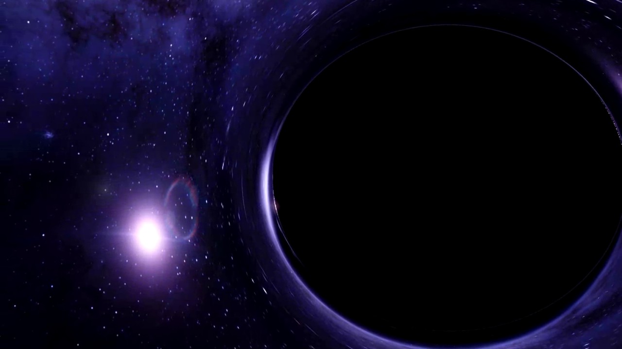
This is as accurate as we can create using todays technology of what it would feel like to fall into a Black Hole.
Here’s an example
I also found this with a bit more digging, but he doesn’t explain his code

Download for free: https://benderitegames.itch.io/wormhole-demo
Wormholes are one of the most fascinating theoretical objects in the universe. It's like taking two black holes, which are already insanely hard to comprehend, and connected them together.
Using math we can calculate the paths of light, and using modern graphics cards we can do th...
I'm trying to use a cubemap in one of my shaders, and I have the shader on a sphere, ViewDir and Normal are both currently set to object space, when I rotate the sphere the cubemap rotates the same direction as the sphere. Is it possible to inverse this so that when I rotate the sphere to the right the cubemap actually moves to the left. Kind of simulating the effect of reversed normals.
That made my head hurt, but....
I think you're saying that as the sphere rotated, the cube-mapping rotated with it. And in that case, what you're really getting is a NON-rotating cube-map...it's mapped to the sphere as if it was "glued" onto it, because you've mapped it all in object space (which is UN-transformed.)
So, if my head was wrapped around your post's meaning...you didn't rotate the mapping at all. You rotated the sphere "later" in a sense.
I think.
And if I'm correct, you can't reverse rotate a non-rotation.
But you can rotate the cube mapping in another space instead, and then ?somehow? pick your alternative coordinates, whatever they are.
Here's a rather old post. If your google fu is strong, you should be able to find several others too.
https://themaxscriptguy.wordpress.com/2014/11/20/rotating-cubemap-in-unity/
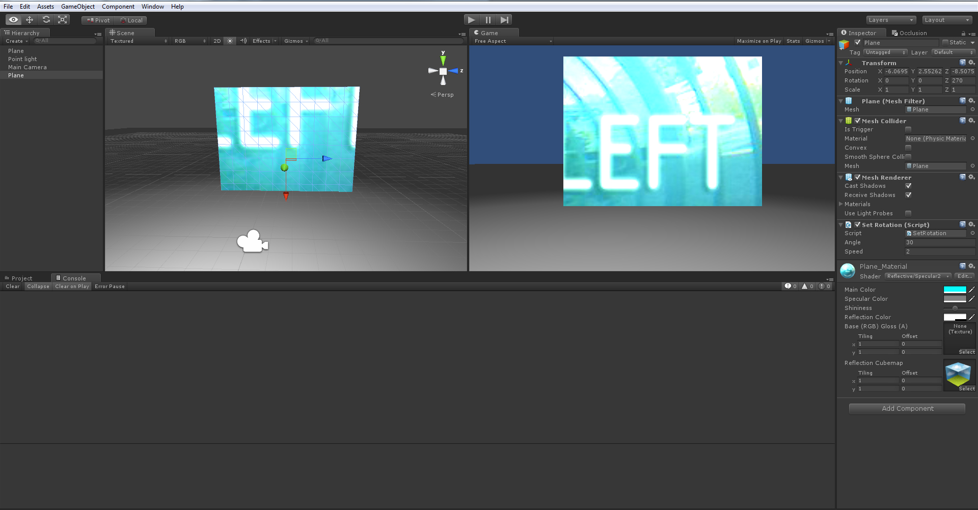
Hello Everyone, In this post we will discuss about applying custom matrix for rotation in Unity Shaders to rotate the cubemap. This can be done to any other shader. Specifically, we will be looking…
Hi, is it possible to pass a Texture2D to a compute shader in a compute buffer?
I want to texture some objects in my renderer so each object struct should have a texture2d for the diffuse, and I was wondering if I could have this as a Texture2D in hlsl or if it has to just be a float3 array
Thanks
Thanks I shall take a look into that!
Hi, how to enable double side face rendering? My leafs on tree are not visible from other side.
You have to use custom shader with culling disabled. If its build in render pipeline, you can make new surface shader and set Cull Off there and if its urp or hdrp, you can make new lit shader graph with double sided enabled. You can also try to find one from asset store.
i am pretty new to the new shader graph and are struggling a little bit
goal: the outline is supposed to be always black, while the color in the center is supposed to be customizable
problem: i accidentally made the center part always white and the outline customizable.
what am i supposed to do here?

With this setup, invert the gradient before sampling (or invert the sampling mask)
You're adding the custom color to the stepped gradient, but that will top out at 1.0 (white) - so essentially you're adding your custom color to the black section of the SampleGradient output
You want the black to be in the center in that case
But if you want the outline to always be black, that approach won't work - you need to add your custom color in a different way
thanks, it worked : )
I'd swap the Sample Gradient out for a Step node first. Then put it into the T input of a Lerp node, with A and B as the two colours.
I checked all and can't see culling or double sided...
That would also give you the ability to parameterize the threshold
i tried this type of setup. but the result should be the same

That works
If you use the step approach, you can also get cheap antialiasing with a smoothstep
Instead of that jagged edge
Yeah that works too. The lerp method gives you more control over both colours if you need it. But if the outline is always black a multiply works fine.
So what did you check?
Would likely need a Texture2DArray or Texture3D
But you can't define a texture of an indefinite length in a struct as far as I know
so Im unsure how Id put it in a struct, and then pass a compute buffer into the shader with the correct stride
Unless I'm misunderstanding
I'm unsure if you can even pass a texture in a struct / compute buffer at all. But afaik you can still store each Texture2D you want per-instance as a slice in a Texture2DArray / Texture3D passed separately into the shader.
Thats what I'm currently doing
I'm just kinda experimenting with rendering with textures rn so its not too good rn
but I can just pass a few textures in and display them

I also implemented non post-processing bloom and have an unhealthy obsession with summoning the sun lol

I have to preface this with I'm not a gfx programmer, but I want to have a shader that i can supply three textures and apply that to a cube (top, bottom, side). I've been googling and I can't figure out the right words to use for searching. Any ideas? Tks!
I figured it out
Triplanar mapping?
Or maybe just UV mapping
yea triplanar mapping
Could you show screenshot of the shader graph you have? Im having hard times trying to understand these incomplete sentences
Hey anyone knows how I can rotate the texture of my sphere via Shader Graph? Because Rotate function changes the color xD

You're supposed to use the Rotate node before the texture sample or whatever, on the UVs.
If you want a perfect 90 deg rotation you can also just swizzle (reorder) the uv inputs too though (there is technically a Swizzle node for that though I tend to Split and use a Vector2 instead)
Can someone explain me how I can archive that this red overlay thing rotates with the sun position around this sphere ? xD PLS

I learnt more about texture mapping on a raytracer
and about how to apply different maps with PBR
god its crazy how good simple techniques look


whats the difference between sprite lit and lit material?
Hello there! Could someone tell me if it's possible to import vertex color in mesh from Blender to Unity? Want to use in shader, but whenever I import and plug vertex color in albedo to check, it's just all white. Tried FBX and OBj, nothing works. But if I use polypaint, I can paint the vertex color on mesh inside Unity. Baking to texture won't be an option for me, because I want to use vertex color as a mask for vertex position
Also checked the expoted models from Blender in Meshlab and Obj shows painted vertex colors, so they do export, but don't make their way into Unity
All info that I've found seems to be obsolete, because people are mostly telling to write a custom shader. However if I can vertex paint inside Unity and see it, it means that shader already sipports vertex color, right?
should be pretty straightforward 🤔
and yes if you can vertex paint and see it in Unity then the shader supports it
Sprite Lit is for sprites, works with the 2D lights / URP's 2D Renderer. Lit is mostly for 3D objects.
thank you\
Probably want to do a Dot Product with the Position and a Vector3 property storing the Sun Direction, rather than using a Split.
follow up question, why when I have a capsule does unity make it a 3d image when its 2d? it just a picture of a capsule. I have a pipeline and it has the 2d render thing on it so why does it default to 3d and how to I make it 2d
Show a screenshot of what you mean?
Unsure what you're referring to exactly. If you mean the capsule object that's a 3D mesh. If you want to stick with 2D you'd want to create a Sprite and apply a sprite texture to it.
like I went to create 2d sprite capsule
idk how to take a screenshot of what I mean as the problem is on overarching thing
I can take a whole bunch of screenshots that could better explain my problem if you want
im sorry if my explanation is crap, im very confused myself
Finally found a solution randomly trying out everything. Exporting in .dae format worked. Too bad it's much larger in size than other formats
ok so let my try to explain it the best I can, I have this capsule sprite which is literally just a picture of a capsule that I made blue

I followed the tutorial by brackeys to make the rendering pipleline


when I go to edit the player sprite graph in order to give it an outline as directed by brackeys other tutorial, it has the sprite as a 3d object and that completely fricks it over
what has the sprite as a 3d object?
i can tell its a 3d object because in the preview instead of having a picture of the capsule, I get a sphere that I can rotate
You mean the Main Preview in Shader Graph?
that doesn't really matter too much - but make sure you're making a sprite shader
also pretty sure you can make the preview window show one of several shapes/meshes
You should be able to right-click and change the mesh to Quad. Otherwise just save the graph and use scene view to preview it.
Hello


Can anyone help me with masking the left / right side of an object in the shader graph? I know I can use world position on the x axis, but that is world position so it breaks if you don't look at it from the front. I want it to be relative to the view
Screen position doesnt work either since that only works if the object is in the center of the screen
Use screen position node but you'll need a way to signify the "center" of the object to compare with
What about View space then? I assume you need it centered on the object so can also offset it with the Position from the Object node transformed from World to View.

Alright Ill try that
for an example of an error that it causes, heres a picture of me trying to make an outline on the left side

notice how in the preview it is mirrored and I can rotate it
Right-click in the Main Preview and you can change it to Quad.

But you can also just see the preview on nodes so not sure what the problem is

The material might be using different values if you edited the property after creating it
how would I know if this is the problem, and how would I fix it if it is?
Click on the material in your assets, check what values it has in the inspector
imagine calling it a capsule and not B E A N
also, notice how when I add the outline the the original "B E A N" it is messed up adn like white and dark blue stripes are on it


Thickness of 0.5 seems much larger of an offset compared to the graph. Change that value to something lower.
I only made it that big to see it something would happen

its the same thing if its small
if I ain't mistaken the bottom left corner of screen pos is (0, 0) right?
im pretty sure its top left
unless unity is built different
(0,0) is bottom left
I would assume the video goes through fixing this. If not, maybe find a better tutorial.
The subtract is leaving negative values which is causing the blue stripe. Can use a Saturate node to clamp the value between 0 and 1.
Adding orange to cyan is resulting in the white. If you want to overlay the orange ontop of the cyan you need to use a Lerp or Blend (ovewrite mode).
thank you very much, ill see if this works. Im assuming that the tutorial is in a way older version where add is the right one to use
oh, but I dont want to overlay them, the orange should be just outside the blues range cause of the tiling and offset. Its supposed to make an outline
see how I offset it then find the difference of the origional and the offset one

oh wait i think i have a solution
nope nvm
I tried adding space outside of the sprite so that the offset had a place to go but it didnt fix anything
Anyone know a good source of materials to test out a PBR renderer?

This is what I'm trying to replicate
One of the blender default Matcap shaders

This is what I have rn (I'm working on the rim lighting first
Like I said earlier I'm using world postion to get the right / left side of it btu that breaks if you don't look at it from this angle.
I just tried it and screen position doesnt work either.
Anyone has any suggestion on how to go about getting a mask for the left / right side of an object from the pespective of the camera without using screen position?
Hey guys Im having an issue with making a water texture that has a sort of edge foam where it connects with land but I cant find any good youtube tutorials that use the new version of shader graph (Im a little new to shaders aswell)

In like 2 minutes you can throw a Bloom post processing effect into your game and instantly change the entire aesthetic of your game!
In this Unity Tutorial we will be looking at installing the Post-Processing package and playing around specifically with the Bloom effect which adds a glow or neon effect to our sprites/models.
Feel free to chec...
this video shows how to add a neon effect
but it adds it to everything
in the project
i just want it on 1 object (it uses post processing bloom)
How do I shift/rotate the hue of an object?
Is it possible to create a shader that hides half a character but still cast shadow? (It's the only thing I can think of to maybe achieve a full body first-person view with shadow without the camera clipping in the body). Open to other ideas too :)
I just recreated one of the matcap shaders from Blender in Unity
What do you guys think? First one is Unity second one is Blender


Hello! I have a little question about shadergraph. I want to acomplish the typical texture transition shader, but i want to transition based on lightning.
Basically:
-Outside Light area: Texture1
-Inside Light Area: Texture2
Is this possible with the current shadergraph?
@vague forum directional light or other lights?
mostly spot and point lights
ah I don't know much about that sorry
ok no problem 👍
I have a quick question. I created a .png with my tiles and want to put a shader on 1 type of tile in the tile pallet. Can you do that? Or does it have to be a single sprite outside of the tilemap/tile pallet?
I did it! using custom function and some hlsl code
Anyone can tell me how to apply backface culling on my leaf materials?? Can't find anywhere that option...
Hi, so I've decided to go for this option and instead store an index with each object for the texture it wants. Basically pass 10 "materials" (diffuse, specular, refl, etc) in a Texture2DArray but I don't know how to pass a Texture2DArray to a compute shader. Does anyone know?
There's only ComputeShader.SetTexture
Ok I'm so sorry, I shouldve just spent 5 more minutes googling haha
Figured it out
Unity Forum
Hi, i need to create a render texture and set it as a Tex2DArrayto a compute shader and then work on every texture in the array. How one can access a...
Hello, I was finally able to position the hair texture from the shader

instead of the transform position
but cant seem to understand what that extra white lines are
anyone with any input as to what it is?
its present in the preview aswell

found the problem needed a little more alpha border on all sides of the texture 😄
Can someone explain me this sentence for dummy please?
Because Im wondering where I get the source and dest inside RenderPipelineManager.endFrameRendering.
"If you are using a Scriptable Render Pipeline (like HDRP or Universal RP), to blit to the screen backbuffer using Graphics.Blit, you have to call Graphics.Blit from inside a method that you register as the RenderPipelineManager.endFrameRendering callback."
@shy quartz BuiltinRenderTextureType.CameraTarget probably.
hmm could you elaborate fruther where I get the source from?
as far as I can see the dest takes the BuiltinRenderTextureType.CameraTarget but where do I get the source?
You get a temporary rt.
You blit from camera target to it with your shader.
Then blit from your temporary back to the camera target.
hmm never done it before, do you have a code ref? already browsin through GitHub code examples but they use the builtin OnRenderImage
If you're doing fullscreen rendering, I recommend just using URP's Renderer Feature API and HDRP's custom post processing API.
thanks 🙂 I went:
Custom Pass Volume -> Custom Pass -> my custom material shader
Im a littlebit wondering because only my placed prefabs are included in the shader while it has no effect on the terrain, grass and trees
Hello, do you guys know what am I missing for the fresnel to overlap my texture?

Im making shapes in the shader graph, and im trying to make triangle with rounded corners. I have the triangle but I cant figure out the corners. Idk if anyone ever tried this in a shader graph, I can only find HSLS snippets online. No luck in converting them to shader nodes either.

While it's GLSL, this is the best resource for making shapes that I know of : https://www.iquilezles.org/www/articles/distfunctions2d/distfunctions2d.htm
They're signed distance fields but turning them into the actual shape just requires something like a step/smoothstep, or divide by ddxy. Subtracting a value from the result before that will make it round, as mentioned near the end of the article.
Ah yeah, I saw some of these on ShaderToy. Thanks
I'm trying to turn this shader code into shadergraph nodes but I'm having a hard time understanding what I'm looking at.
Could anybody give me some pointers, specifically in how I can get the matrix "mat" info into and turn it into a vertex position

Unfortunately I'm pretty sure shader graph still does not support StructuredBuffer
the data itself is a 4x4 affine transformation matrix, which is essentially the position, rotation, scale all baked into one data structure
Hi
I'm currently making a simple shader with Shader Graph. I am basically copying the shader that this video has: https://youtu.be/GGTTHOpUQDE

Open Projects are small, open-source games where the community of creators is free to collaborate and contribute actively to the entire game development journey. In this first devlog, we're going to discover the ideas and the process behind the cartoon look we developed in the first Open Project, an action-adventure game titled "Chop Chop".
⭐ ...
The subtractive shadows and everything works well
Buuuuuut
When I try to support Baked Lighting

All becomes turquoise

Does anyone can help me please?
And yes, when I remove this part of the graph everything just works fine
If the URP/Lit shader also ends up as turquoise/cyan, it's not the graph but a bug with the baked GI. You can clear the GI cache under Preferences which should fix it. I've also heard just rotating the directional light forces it to rebake too.
Thank you a lot, I'll try it
Hey there quick question: as I understand, any SRP doesn't support multipass shaders. The easiest way around it is using multiple materials, but when you add the second material to the mesh it gives a warning saying to consider using multiple passes for performance.
So the question is: what's the difference in performance between multiple passes and multiple materials?
How can I recreate blender's Cavity feature with shader code or shader graph?

Where the edges are highlighted
That cavity effect is definitely not an easy task to do in vertex/fragment shader. It would be better to bake those normals into normal map or actually change the geometry. This type of effects are usually implemented in post processing shader.
is there a way to make this outline look a little more regular?

thats the shader graph


Hi, I cant seem to figure out why my Material wont appear on my mesh?
If I drag the material to any other object in the scene, it appears correctly. Could someone let me know what I might have done wrong here?
I did the same for the checkerboard surface, worked perfectly. Thanks
Ps The material is a beachwood texture, but the mesh appears as a solid colour. (The pink one's I have not yet applied the texture to)

I dont get it... I've tried changing all sorts, I've even imported in to blender, then exported as obj with material, and still when it's in the game, the texture disappears...? I'm at a total loss here lol... So please, if anyone know what this issue is, please let me know. Thanks
the material being renderer just as pink means that there is an error with the material, usually there is an error in the material's shader code. If the material was exported by blender then that might be the issue, AFAIK blender materials and unity materials aren't really compatible
I even tried making one from fresh, I feel like I'm missing something obvious.
The pink thing im not worried about, since I have not applied a material to them yet
I followed YouTube videos to make a material from scratch, starting with just my texture as a normal image file on my computer
I see the shader used in this material is unlit, which is why it has no shadows
then maybe the uvs were exported wrong and that's why it appears as a solid color
and the lack of shadows is because it has an unlit shader
I'm still quite new, and I'm just looking to get the texture to show, with no shadows or anything like that, just the plain texture. Could you tell me what I should select for that result? Thanks
Well I’d just create a new material and use Unity’s built in lit shader, then apply the texture to that
@dusky hemlock
I see, then I can’t really help. You said you exported an obj file right? May try using an fbx which I think plays nicer with unity
I havent tried fbx before, but I've seen the export option in blender.
Also, I should note, the original file is 3ds. Would have first importing that have broken Unity?
Let me see if I can find the file, maybe you could reproduce? (Or anyone reading)
Nope wrong one (deleted)
Don’t have unity installed on my current machine so I can’t try
Hello I am trying to draw a particle system over my custom shader graph but for some reason I am unable to draw the particle system on top of the shader graph shader

The greenish particles is from the particle system


The first one is the material properties for shader graph
2nd one is the material properties for particle system
I tried moving the particle system to another camera still wont work
Okay, what am I doing wrong? I hit save

Doesnt seem like problem in your shader graph. Your render pipeline is not working properly. Make sure your render pipeline asset is assigned to graphics settings
Do I do that in here?

The box that says ”None” should have your rp asset on it. Are you even using scriptable render pipeline (urp or hdrp)?
I have URP installed and imported, but I guess for some reason it didn't make it into the Graphics Settings
Hey guys, I'm gonna try to make a raytracer from scratch with compute shaders to render some meshes
I need a way to transfer information of the meshes to the shader, but the meshes must be of a variable size
While I am able to send a list of tris to the shader, there is nothing that links those individual tris to the mesh which may cause issues later on though it would still work
Is there any more linked way to transfer a mesh in its entirety to a compute shader with the coordinates of all its verts and tris?
So I got my URP working, but now the material isn't scaling to the quad it's on :T Any ideas?

heh. Yeah. You've already hinted at it.
Individual draw calls (well, compute shader invocations) per mesh, and a compute buffer full of triangle data. You're doing it all manually, bypassing the engine, in a sense.
You can send several meshes at once, with a more complicated buffer setup. You know, a buffer with a list of meshes and their starting offsets and length pointing into a 2nd buffer that has all the vert data in it.
Also check into AABB's and culling per mesh, and per triangle, because the fastest polygons are the one's you DON'T draw/trace.
http://three-eyed-games.com/2019/03/18/gpu-path-tracing-in-unity-part-3/
Oh Ive read this guide a long time back haha
Definetly I'm gonna look into alll the optimizations
But here he passes in a list of individual triangles into a compute buffer right?
Instead of a single "Mesh" object with a list of triangles
so each triangle is treated as an individual entity
Since when aren't triangles "individual entities"? I mean, even in "normal" polygon rendering, the GPU processes 3 verts in the vert stage, and rasterizes it and then passes the pixels to the frag stage.
In your case, you're doing all that basically "manually".
Well yeah, good point but what about UV mapping incase I want some textures?
I guess I could store UV coordinates with the tri also, so it should all be good 👍
Tysm
I've implemented meshes before but it was with raymarching so it was crazy laggy

You're answering your own questions. You know what to do. 😉
Hang in there, just dig in.
And yes, ray tracing is laggy. There's only so much you can do, particularly without special hardware. That's what all that RTX 'n stuff is about.
I'm a little nervus to attempt optimisation though Im sure Ill figure it out
You're not likely to pull off ray tracing in real-time.
I'm fine with that, but atleast I hope I can move my camera around without 2fps like with raymarching lol
With a low sample count and reslution to set up scenes and then a render
But raymarching looked crazy good


Im looking forward to adapting these techniques to mesh objects
Hi I created this Shader graph to display a circle on a plane. Can you suggest techniques (besides AA) to make the circle edges smoother (les rigged)?

um so what is the point of setting uv coordinate into local space vertex position? what you want to achieve by that?
There's an Ellipse node that'll do this for you, it divides the distance field by it's partial derivative (DDXY) to make the edge smooth at any resolution.
An alternative is using a Smoothstep, or Inverse Lerp -> Saturate.
On what do I use smoothstep?
No sure how to use ellipse node
Ellipse approach creates smooth borders, but doesn't work with clipiing

Dark boders
You'd use the Smoothstep on the Length node output, in place of the Comparison
hmm
You'd want to use the Ellipse to only control the Alpha of the shape, not colour. Similar to what you're doing currently
But if you're working with alpha clipping you aren't going to get it that smooth as that can't support partially transparent pixels.

Because you're still using the Comparsion with 0.5. I meant to remove that. e.g.

But this still likely won't make much difference with the alpha clipping. You'd need the shader to be transparent (but might mess with sorting too as it doesn't write to the depth buffer)
Hello, i am very new to shaders and i'm working on a 2D urp project. I would like to create a shader with shader graph that looks like the picture and the color can be changed at run time, I would like to be able to modify the inner glow also. So on a given 2D texture it would create this neon effect. Could you good people please give me some directions on how to accomplish this?

Also if possible i'd like to avoid bloom
What do you mean with trasparent thingy? 🙂 .. I just know alpha clipping
This doesn't work for me.. I set color alpha to 0, and its still back

Your alpha in Fragment is staunchly set to 1 over there
Hi, i've defined a struct in another compute shader in hlsl and am trying to include it in my main shader.
Yeh
But I'm getting a "Redefinition of" error, how do I fix this?
I've seen #pragma once be mentioned but it did nothing
I got mixed up in ideas, thanks for pointing out this 😄
In which cases is the y axis flipped in the shader?? I'm using a texture sampler and I'm using a world position value that I get by doing
baseWorldPos = mul(unity_ObjectToWorld, float4(0,0,0,1)).xyz;
where do I need to look for flipped y values??
Can I make a "always on top" shader with Shader graph? Like Gizmos?
Can change Depth Test to Always in Graph Settings (assuming in Unity 2021.2+, which you are given your screenshots) and increase the Render Queue on the material. That should then always render on top of other objects.
Will try
I do not see a Render Queue option material settings
Not sure which flipped values you are referring to from this code. The Y axis points up in world space.
It should be at the bottom of the material in the inspector. Unless that's changed in newer versions :\
yeah i thought it was flipped while grasping at straws but I think I needed to do something like this
Anyone know how t include structs and functions from another file in a compute shader?
    sampler_LevelStencil,
    float3(
        ((baseWorldPos.x * 100) / 24) / (_LevelStencil_TexelSize.z - _LevelStencil_TexelSize.x),
        ((baseWorldPos.y * 100) / 18) / (_LevelStencil_TexelSize.w - _LevelStencil_TexelSize.y),
        ((baseWorldPos.z * 100) / 18) / (_MapHeight-(1/_MapHeight))
    )
).x;```If it makes any sense at all
because i was getting incorrect values by dividing by the texelsize
but removing the last step of the texture i avoid the 1 where it normally repeats
Put those structs/functions in an include file (.hlsl or .cginc) and use #include
Oh that was my issue I was putting them in another .compute without the header
I tried with .hlsl but I had this error

I think its like using pragma once in c but it didnt work
Are you including the file multiple times in the same shader pass?
This was back when all of them were named .compute, lemme try renaming but
🤷♂️

Basically I have 3 files, and I am including the other 2 in the main file, and including the other 1 in the 2nd file
No includes in the 3rd file
I don't think hlsl has pragma once, but you can do something like this instead :
#ifndef SOME_KEYWORD
#define SOME_KEYWORD
// contents
#endif
Oh I see, thanks!
Ah, probably need to change the "Queue Control" first
All the errors are gone now
awesome
but I really hate that when you try to debug shaders which have logic errors it just says Kernel is invalid lol
kinda annoying
for sme reasn this error shows up because of this one


Weird
Maybe I need to reopen
There we go
tysm
@regal stag sorry but seems like the error is still there.

Im getting an error that there's a redefinition of struct Object
Even though this is the only instance of its declaration
Maybe try renaming it?
The type is also ambiguous in all definitions
Alright
But same goes for Ray
Nope didnt work
Weird
Huh

Nvm
that was just a regular error my bad
Oh hell yeah it worked now

After building the errors are gone too
Awesome, thanks for the help!
What does the queue in general?
It controls the order in which things are rendered
More, is more in front?
Higher is rendered later yes. That doesn't necessarily mean it will show on top of other objects unless you also change the depth/z-testing (e.g. Always, meaning no matter the value in the depth buffer, always render the pixel)
Hello! I'm having an issue with a magnification shader (and other transparent shaders) not appearing in game view while they appear in scene view.
I'm using this: https://github.com/microsoft/SeeingVRtoolkit/blob/master/Assets/SeeingVR/Shaders/Magnification.shader
@regal stag my case is so... ghh.. I have 3 objects. Each has own material with same Shader. I need this "group of 3" to be always on top, so I changed Dept Test as you said to "always". And it works. But the trouble is that these 3 objects start to overlap them selves :/, where I need them to respect Depth.
The green is actually in front from this view

If I play with queue, I can get it work form one view, and its broken from other. So its not an option.
Wo it actually doesn't work with any of the Depth Test options.
Its some bug with Transparent ?
It's not really a bug, this is just how transparency works. Transparent objects typically don't write to the depth buffer so they can be blended correctly, but it also means they can't be sorted per-pixel. Instead it just sorts based on whichever origin is closest to the camera.
And if Origin is same, it can look messy?
Probably yeah. They'd either always render in the same order or I guess due to floating point differences flicker between them as the camera moves?
Doi. It really checks the origin. I moved green one 0.0001 in camera direction and it renders as in front. Oc from other side is wrong again 😄
I could check in Update camera position relative to my object, and offset parts as needed :D.. very Hacky
Does anybody know why unity_CameraProjection in blit (urp render feature) only works for Single Pass Instancing? It seems to be wrong when using multi pass rendering...
Hi!
in what space do shader recieve vertex position?
ie what is it space of v.vertex before the "UnityObjectToClipPos(v.vertex )"
is that really a object space? i need confirmation

It's the positions of each vertex stored in the mesh. Which yes is referred to as object space.
Though it may also depend if the objects are batched (static or dynamic, SRP batching is fine), as that could combine multiple meshes together. And in the process I believe that changes the vertices to be stored in world space, and sets the model matrix to just an identity matrix.
Thank you! Then i wonder why cant i replicate this shader with ShaderGraph?


The Position port is expected in Object space, not Clip which is why what you're doing isn't working. You don't really need to do UnityObjectToClipPos in Shader Graph as it does it for you behind the scenes, but this does make overriding the clip space z value difficult. :
I guess you could convert your result back to object with a Multiply node using the View Projection matrix in first input (obtained via Transformation Matrix node), then Transform node from World to Object. It's going to be more expensive though.
Tbh since the shader code is unlit you could probably just use it as is.
tried that


mmh i want to combine that effect with some shadergraph shaders that i already have
calculates depth of object so it will render beyound far clip
i can manualy assign position with float to replicate effect, so its possible with shadergraph. but something with matrices prevents me from getting correct value automaticaly
best i can get is that -


hmmm... my guess is that object position in Shader Graph is not model position after all
Is it possible to check if a fragment is inside an object in post processing shaders?
Also please tag me if you have an answer, so I can see
ive found that in some transformations W and Z swapped...
eh
does anybody know why there is a distortion in the skybox like that?

it looks fine from this angle

but if you turn around a bit you can see that the skybox is distorted weirdly for some reason
Answered the same question a few days ago so just going to link that : #archived-shaders message
Hey guys, i have a question regarding optimization for my raytracer
I'm tracing the tris by going through a for loop and finding the closest one, but for loops on the GPU still happen one after the other
Earlier with raymarching that needed t happen as information was carried over from the previous iteration but here I dnt need that
just a list of all the intersection points and distances between the ray and every tri in the scene
but Im unsure how to implement this such that all of the calculations happen simultaneously and then the closest hit is chosen
Anyone have any resources on how to achieve something like this?
I need to do an intersection test for each pixel for each tri in the scene
The pixels already happen simultaneously its just that in each pixel the tris are traced one after another
The three-eyed games tut you've read already does this.
They have a "ray" struct that they pass the hit info through.
Each thread has its own ray and is doing its own calc...in parallel. With its own local memory and data. All reading your triangle buffer at the same time.
In a compute shader, that's still true. So regardless on if you're using compute shaders or not, you still have local memory for each thread in a thread group. So all 64 processors in the group (for an 8 x 8 x 1 thread setup) are running in parallels using their shared program instruction counter, stepping through the program in lock-step.
So yes, you're going to trace each ray through each triangle.
So research polygon/ray intersection tests. So each thread can ask "Does this ray intersect this triangle?" in a quick calc. THEN you can check at the pixel level if a hit.
That's why you should have mesh bounds, mesh lists for its triangles....you can skip entire sets of polygons if a mesh, say, in the lower left corner isn't hitting any of the current 64 rays being looked at. If it has 100 tris, you can skip all of them. But if one of them hits, all threads will have to step through crap.
Ray tracing is slow for theses reasons.
Quick summary, have to go to work. Good luck.
In the three eyed games tutorial they dont do all the triangles in parallel though

The optimizations are for AABB's..
Hm I think i need to do a little more reading haha
but yeah ive heard of mesh bounds and such.. I think those are my top priority after I get the shading down
But I was just wondering if instead of finding the intersection (if any) with tri1, then with tri2 and so on after each other
If you could do every triangle together in a pixel
And then in that pixel, the intesersection point is with the closest tri
Yeah, you've got the triangle test.
That's what's happening IIRC.
I don't understand, but I've GTG right now. Sorry.
What he's doing is (there should be an AABB mesh intersection test before that code, so you can skip the whole mesh, but...)
is that he's stepping through the triangles for the current ray. The current ray is really what you're calling current pixel...because light is bouncing around the scene back to that pixel. Ping ponging around off stuff. But it all gets back to that pixel that you're looking at. IIRC
I understand, if you have any clue how to do what Im trying after work thatd be great but
In that current pixel/ray he is stepping through each triangle, yeah
in a for loop
But seeing as finding the intersection between 1 ray and 1 triangle isnt required t find the intesrection between 1 ray and the next triangle
What if I could find the intersection between 1 ray/pixe and all triangles that are in its path?
At the same time
Instead of a for loop, in parallel I find all intersections and pick the smallest one
This is merely a thought btw, Im a long way away from even implementing the simplest optimisation so this is more of an experiment down the line
I'm not sure it matters, but I haven't had time to think about it.
But multiplication is commutative. So IDK that it matters if you do 100 pixels x 10000 tris or the other way around, you're still ending up with a lot of loops. I think you're saying you want to invert the parallelism. IDK, head hurts.
But we start at the pixel level, and trace a ray through the tris. Inverting that means you cannot process multiple pixels. Robbing Peter to pay Paul.
IDK how to parallelize an already parallel task. And I'm rambling right now, Sorry, GTG.
Thank you so much for the clarification man 
But yeah I understnad what you mean, I have a newfound respect for the people who make renderers realtime
Im sure that parallelizing the tracing along with the pixels is possible through dedicated hardware and smething RTX may do, but I'm not that dedicated lol
Just gonna implement AABBs and whatnot and make some cool renders 👍
Hey guys,
I want to do a depth custom pass in HDRP. But the example I'm trying to rebuild does probably not read the DepthNormals from the camera correctly?
Im using this material in custom pass volume:
Shader "Hidden/DepthShader"
{
    Properties
    {
        _MainTex ("Texture", 2D) = "white" {}
    }
    SubShader
    {
        // No culling or depth
        Cull Off ZWrite Off ZTest Always

        Pass
        {
            CGPROGRAM
            #pragma vertex vert
            #pragma fragment frag

            #include "UnityCG.cginc"

            struct appdata
            {
                float4 vertex : POSITION;
                float2 uv : TEXCOORD0;
            };

            struct v2f
            {
                float2 uv : TEXCOORD0;
                float4 vertex : SV_POSITION;
            };

            v2f vert (appdata v)
            {
                v2f o;
                o.vertex = UnityObjectToClipPos(v.vertex);
                o.uv = v.uv;
                return o;
            }

            sampler2D _MainTex;
            sampler2D _CameraDepthNormalsTexture;

            fixed4 frag (v2f i) : SV_Target
            {
                fixed4 col = tex2D(_MainTex, i.uv);
                float4 NormalDepth;

                DecodeDepthNormal(tex2D(_CameraDepthNormalsTexture, i.uv), NormalDepth.w, NormalDepth.xyz);

                col.rgb = NormalDepth.w;

                return col;
            }
            ENDCG
        }
    }
}
what I want

what I get

the blue sky is wanted tho 🙂
Could just be the range of the depth buffer leading to everything looking too close together (similar grey). Does it change if you reduce the distance between near and far plane of your cam?
I don't work in HDRP but this might help with getting the depth & normal textures. https://medium.com/@antoinefortin_64750/unity-hdrp-g-buffer-for-post-processing-f7d4f8840944
Also this (but only includes depth) : https://mitchmcclellan.com/depth-based-post-processing-in-hdrp/
naaah does not have effect^^
niceee

Anybody knows how to render to the depth (also in depth prepass) in custom a URP shader?
I am writing to this output:
struct FragOutput
{
    half4 color : SV_TARGET;
    float depth : SV_DEPTH;
};
But this doesnt seem to work for depth prepass
You'd want to make sure the DepthOnly and DepthNormals passes are also editing the SV_Depth, not just the main pass.
ah the shader does not have these passes yet. are there any good examples on how they should look?
ok found it in the default lit shader
thx
Hello guys,
I have multiple Shader scripts that I want to convert to Shader graphs, is there a way to do this without me recreating it manually in Unity?
Please tag me on response
There is no automatic way to convert shader code to graph form, it would need to be recreated manually.
I guess I gotta do that 😄
Hey can anyone help me with a smal thing