#archived-shaders
1 messages · Page 229 of 1
(this is how you normalize, just reverse , divide a vector by it's length)
if you want a circle just try a distance function
I'm trying to make my material look less like the same tile. I'm trying to do things like flip them 180 degrees in random spots, and move the tiles left and right slightly. does anyone know of a good shadergraph tutorial for this? or just a unity Asset that will do the job?


I'm not sure if this is a thing yet
eh
nvm
it seems like bricks wouldnt work well
Is there a built-in pipeline shader that can have two different color tints on different parts of the texture?
Similar to what he did here, but with normals and everything setup like the built-in standard shader?
https://forum.unity.com/threads/customize-multiple-colors-on-material.376779/
no, but you can make one
well
maybe on asset store, not anything official
also, if it is possible, do not use built-in pipeline
I think amplify shader editor may work with builtin still
Yeah, I really want to switch to URP. I know this would be pretty easy in ShaderGraph, but I'm taking over a project that's halfway done already, so not sure how much trouble switching the pipeline would be
depends, how many custom shaders and weird rendering magic the project is doing
That is, a vector space is a group of directions?
what do you mean by "vector space"
yes I guess?
you could also define them as points
like
(1,2)
could be a direction with a length
or a point of 2D space
the bricks were just a stand-in texture, I'm flexible. I'll give it a try! thanks
Coordinate system, I guess.
Sorry, I'm not very good at shaders, so I can express myself incomprehensibly.
I am trying to create a "mask" effect between two prefabs.
FAR more robust than just slapping a SortingGroup/SpriteMask on it, which I also cannot do because the assets I need to mask out might be above or below another asset that I do not want to be masked.
I -think- what I want for this is an SRP "Rendering Layer Mask" but I can next to zero documentation on what this thing is or how to use it
That field when moused over has a tooltip that says it can be used with the SRP "DrawRenderers" command
but where/how do I "use" this "command"
I think what im trying to achieve is a shader effect
but Its hard to describe verbally without just seeing it, and I cant just show you it without making it first
you might want to look into stencils
Hmm yes, stencil buffers, cutting holes in things, that is what I am trying to do 🤔
Ill do some googling on shader stencils
Is it possible to write to an RWStructuredBuffer<T> inside a custom function inside of an HDRP ShaderGraph? Right now it just absolutely refuses to work even with the proper Graphics.SetRandomWriteTarget setup

Why are the URP render mask layers PHYSICS layers and not SORTING layers?
I see no reason at all why it has to use the physics layers to decide how something should be rendered, isn't that how the sorting layers, which sort things being rendered, work?

like, this seems totally insane to me but maybe im just not clearly understanding the reason why it uses physics layers instead of sorting layers?

Guide for using the Stencil buffer in Unity to create portals & windows when using the Universal Render Pipeline. This info is also suitable applicable to...
I tried to follow this tutorial, but it doesnt work
even though my set up is identical to theirs, nothing renders at all
Do you have a link to an actual functional Stencil buffer tutorial for Unity URP? Preferably one that actually uses rendering layers and not physics layers
@tight phoenixWhat's a physics layer?
Physics can use the layer system, but I don't know of "physics layers".
Layers are layers to me.
Cameras use them, to determine draw call order. That groups your shader calls.
I am doing a 2D project and 'Layers' are synonymous with 2D Physics Layers, which may have contributed to my confusion/problems
regular 'layers' are physics layers
and things like triggers and collisions are per layer
Does anyone have any working examples of shader graph + stencil buffers?
I can't find any online
I am trying to cut a hole in multiple SpriteRenderers to reveal other sprite Renderers, or the opposite, only render a group of sprite renderers masked by a stencil buffer
Ideally with transparency, not just binary visible/not visible
If they were sorting layers it wouldn't be usable in 3D games 🤔
Hi I followed a wind shader tutorial (https://youtu.be/L_Bzcw9tqTc) for shader graph and everything worked until I wanted to add this lerp so that the bottom of the swaying grass won’t move and now my mesh has these gaps as seen in the photo. what can I do about that?


Let's learn how to make realistic grass with Unity Shader Graph!
This video is sponsored by Unity
● Download grass assets: https://ole.unity.com/grasssway
● Art That Moves: https://bit.ly/2VW85He
● More realistic vegetation: https://bit.ly/2EAxC5d
● Mesh Generation: https://bit.ly/2u7vee3
♥ Support Brackeys on Patreon: http://patreon.com/b...
The problem is you're using a "flat shaded" model, which basically means you have duplicated vertices. at each corner. And your graph is not in any way making sure the "duplicate" vertices for each corner all stay in the same spot
so they're drifting away from each other
One solution is to use a model that doesn't have duplicate vertices
how does the cube have duplicate vertices?
Each corner actually has three vertices in the default unity cube. One for each face it's part of.
It's so you get flat shading
Because a mesh has a normal per vertex, and if you want the three faces to be perfectly flat shaded and not shaded as if they smoothly curve around the corners you need to have separate vertices with separate normals
I've already asked this question before and gotten very helpful answers but I still don't have the exact result I want.
Essentially I'm trying to create a shader similar to how picoCad renders it's objects. Example: https://img.itch.zone/aW1hZ2UvODg0NjIzLzUyNTM2MjIuZ2lm/original/Wl%2BbXz.gif

I already have a screenspace dithering effect that displays under certain lighting, but I don't know how to make it a solid shade when the lighting gets even darker
I've been using a shader which Cyan, on this discord provided when I had similar questions earlier (which I realize now that I forgot to reply to their help and I'm sorry about that lol but it was super helpful) changes which what shade of pixels are visible on the dither texture, which is really close to what I'm looking for, but not quite
which is this shader

Just to me more clear is ideally I want to have a shader like this:

and the main issue is that I don't know how to make it switch from the dither shading to the step-styled shading when the light gets low enough
any advice would be awesome
Hi all. I'm doing a Blit to a renderTexture containing some data for the GPU to use (it's related to vfx)
It used to work back in 2019.4, but now for some reason after upgrading to 2020.3 and ONLY in my laptop, there's a weird problem...
The target RT is 64x6 size. So, 6 channels of 64 float array
The thing is, when all 64 float are supposed to be 0s, some floats above [32] gets full value (or flickers, idk)
If all 64 float has a tiny bit of values, some of those floats above [32] gets more "balanced", but still "corrupted"
And i use it like so
        _buffer.SetData(toneEqArray, 0, 0, w); // Toned Spectrum
        _buffer.SetData(tonePeaks, 0, w * 1, w); // Tone Peak Amp
        _buffer.SetData(pitchToneArray, 0, w * 2, w); // Pitch Tone
        _buffer.SetData(pitchFreqArray, 0, w * 3, w); // Pitch Freq
        _buffer.SetData(pitchAmpArray, 0, w * 4, w); // Pitch Amp
        _buffer.SetData(filterPass, 0, w * 5, w); // Filter Pass including Bypass(volume)


        _material.SetBuffer("_Waveform", _buffer);
        _material.SetInt("_Width", toneEqDampen.Length);
        _material.SetInt("_Height", texHeight);

Graphics.Blit(null, spectrumTexture, _material, 0);```It does feel like a mipmap issue, but it's already initialized with FilterMode.Point
        spectrumTexture = new RenderTexture(width, texHeight, 16, RenderTextureFormat.ARGB32);
        spectrumTexture.filterMode = FilterMode.Point;
        spectrumTexture.Create();

        _buffer = new ComputeBuffer(width * texHeight, sizeof(float));

        // Debug.Log("XY: " + width + " : " + sizeof(float));
        var shader = display.bakerShader;// Shader.Find("Hidden/Lasp/WaveformBaker");
_material = new Material(shader);```Praetor is correct that the model has duplicate vertices but the problem is the UVs are causing the seams/break. If you just need a vertical gradient (for T input) use a Position node (object space) into a Remap from -0.5, 0.5 to 0, 1. (Though those values may vary for different models)
to fade out a GameObject with multiple MeshRenderers what would a good solution be?
(urp)
Can use a Posterize node after the Dot Product or Smoothstep to get the stepped/banded shading. Also Comparison node on same output and Branch to switch between the two styles.
I do feel like there is more light levels in the example gif though. There's also probably a better way to achieve it but can't see it right now.
my idea is I should have versions of the materials that are transparent and swap them before the fade out
then transition,
but when doing this (swapping opaque materials with transparent ones) the swap would be notable for some meshes, because transparent renders differently
Maybe instead of true transparency, keep it opaque but use dithering + alpha clip instead
thanks but that would not work with urp/lit shader though? - would have to make a custom one?
Yeah you'd need to make a custom one
I feel trying to replace the default shaders is problematic. maybe some people do that on a regular basis. though the default ones are probably very optimized or at least complicated. also from a point of view of maintaining them
(mainly talking about lit one)
oh wait probably ignoring shader graph here lol
The URP/Lit shader is quite similar to the Lit shader graph, which handles all the lighting for you. Just need to add the properties and Sample Texture 2D nodes for albedo, normal, metallic/specular, etc. Might also be able to find a graph online that replicates the URP/Lit. There's a Dither node so adding that part is easier.
bingo. thanks for refreshing my memory 😄
I thought shader graph lit should be pretty much the same as the normal lit shader
you say quite similar. is there a difference in behavior you know about? (not an implementation difference though, as they must obviously slightly differ)
I say quite similar because the lighting style is the same afaik but the graph is blank and wont have any properties/textures
alright 👍
hm
alpha clipping means rendering it transparent with a clip threshold, is that correct?
which mean using the transparent shader - therefore I'd have the "transparent rendering artefacts" still?
meaning if I didn't want that I had to go with dithering
You can still use alpha clip in opaque too
but that does not fade for materials with alpha 1 everywhere I guess
Yea you'd need the dither too
except I'd do it in the shader perhaps
oh
have you done that before?
are the results good?
combining dither and alpha clip then?
didn't think of that that sounds good
hm yeah you said that. sorry got that wrong
well thank you
Last I knew, SG doesn't support stencils, but I think it's on the eventual-list. I can't imagine them not wanting support for a hardware feature like stencil.
what is the colorspace of the Color node by default? HSV or RGB?
aight thanks
Hello! Someone knows how to use a video in shader graph???
imo, it seems like the strategy should be to create the banding first, and then if it is in a certain band create the dither effect. I don't use shader graph, so I don't know if there are specific nodes to do that easily.
- Get illumination
- transform illumination into stepped/banded illumination levels
- calculate remapped level so that it is 0 if below dithered band, 0-1 in dithered band, and 1 above dithered band
- pass remapped value into dither pattern to get dither pattern for your current band. If you're outside the dithered band, it will just give you a solid color. otherwise, it'll give you the pattern.
- Combine original banded illumination levels (2) with dither pattern (4) to get your final color

Im trying to edit someone else's shader to use a texture as a mask instead of their math as a mask
I don't really understand it so I don't know how to get it to do what I want
I have the texture input as a mask (I think) good to go, but I am struggling to position the mask in world space where I want it to be positioned

they did this, but I dont understand how any of it works so I can't modify it to do what I need
TLDR: How do I position a texture in a shader at an explicit position in world space?
I'm implementing a custom render pipeline. Does anyone know if it's possible to schedule a compute shader as part of the pipeline, perhaps in the ScriptableRenderContext?
Specifically, what I'm looking to do is precompute some information over each (preferably culled) vertex, which I'll eventually need to access in the vertex shader, but if it's possible to inject a compute stage I think I can figure out the rest.
I can't find any documentation around this on Google - it's just people looking to run a compute shader between the vertex and fragment stages, which doesn't seem possible. I want to run it before the standard pipeline, but after culling.
FOW progress: https://youtu.be/MTN1oZf4t-I
anyone ideas how to use a int bitmap 128x128
and render it with some shader magic into a nice looking FOW? (using build-in)
I am currently using a Color array and putting that into a texture each frame, which is even less performant than my old FOW system.
So that won't do

Hi there,
I've been experimenting with making a completely new FOW system for my RTS game.
The old system uses Ray-casts around each unit on a circular plane to detect obstacles and builds an umbrella shaped mesh, which is then used as a mask for the FOW camera which renders this into a render-texture which in turn is then used by a projector.
...

The left node graph scales from the center of a texture instead of the bottom left coordinate
but it stops scaling from the "center" of the texture if I use an offset parameter in the Tiling and Offset
I want to scale from the center of the offset, how do I do this?
There must be some math to combine these two concepts, center-scaling and offset position
I think I answered my own question if someone else searches this:
https://docs.unity3d.com/2018.1/Documentation/ScriptReference/Experimental.Rendering.ScriptableRenderContext.ExecuteCommandBuffer.html
combined with
https://docs.unity3d.com/2018.1/Documentation/ScriptReference/Rendering.CommandBuffer.DispatchCompute.html
Now I just have to figure out how to get the vertex stream into the compute shader and pass forward the generated info

Im so close but I dont know whats wrong
if I use the cut out position in the Scale from Center portion, I can set "where" it scales from
but when I try to actually use it in the Mask, the "center" is never centered right
the scale from center / position doesnt align perfectly

These two values control where the "center" of the scaling happens, but they also dont
if I change them to any other value, it does move the "center" but then it also stops scaling from the "center"
What am I doing wrong!?!?!?! I don't get it , atall
Getting frustrated
I think this might be what you want?


Negate
Didnt work here, where do I put it in the flow?


nevermind, it goes here

position 0,0 in theirs is the bottom left, but for me because of my scale offset stuff, its dead center hrmmgh
because I need it to scale from the center, but also offset
everything keeps screwing up
every time I offset it, it stops scaling from the center
I cant figure out how to "offset" it the RIGHT way
Did you try what I posted above?
Trying it now

it sort of works but the position is still wrong
I know I need to move the final thing -0.5 -0.5
but i dont know where to insert that movement that doesnt fuck up the positioning/scaling in some way
I think Add it between the Vector2 and Subtract nodes.

I'm unclear on which "between" vector2 and subtract refers to
vector 2 goes to a subtract, and it goes to the add at the end, if I add it back after that vector2, isnt that the same as just the vector 2 being zero?
I mean the Vector2 in your Cutout Position group
:O That did work
The shader is very close to being done
Theirs uses the Screen Position as part of the Cutout Position

the "Cutout Position" is a world space coordinate
you can see in the preview theirs is a perfect circle on the sphere
if I plug what I have in, it does not show a perfect rectangle because its not taking the screen position into account yet
I need to now somehow use the screen position hhmm

I did it all on my own, I'm not a total moron!
plug in the screen position in place of the UV coordinate
😺
@regal stag Could not have figured it out without you


in practice it works exactly as I was hoping, its cutting a hole in my SpriteRenderer, but more importantly the hole has gradiated transparency, something a simple SpriteMask doesn't have
I am having trouble on installing Universal Render Pipeline package anyone knows something?
THANK YOU SOO MUCHHH IT WORKED!! I tried all night and couldn’t get it to work, I’m so happy 😭
How would I create a shader similar to the metal mario effect in mario 64?

Hey, noob question: I have two meshes that have different rotations and I have this water-shader (shader-graph, https://alexanderameye.github.io/notes/shaders-done-quick/). Can I somehow ignore the mesh rotation so that the water flows in the same direction?
If the water is always flat, you can use a Position node in World space, Split and use R and B (aka X and Z) axis into the X and Y on a Vector2 node. That can then be put into the UV port on the Gradient Noise (or Tiling And Offset before it)
Thanks, I'll try it out. For now it is supposed to be flat, but would it also be possible in case I add height-movement?
Yeah should be fine
Pretty sure they use a matcap style shader - basically using the Normal Vector in view space to sample a texture
It worked, thank you 🥳
Any way to implement like an event system in shadergraph?
Like if I shoot an object with a bullet, that object will have a dissolve effect
not the way to go about it
make a material manager that changes the values of the material and other objects have access to that manager
material manager?
materialmanager.cs or name it whatever you'd like
then access the materials made from the shader you want to edit
oh like a material manager script
And then switch the game objects material to the material with the dissolve effect once the bullet hits?
not necessarily

✅ Get the Project files and Utilities at https://unitycodemonkey.com/video.php?v=OzyLWXTr3Io
Let's make this Awesome Construction Shader Effect built in Shader Graph!
🌍 Get the Complete Builder-Defender Course! ✅ https://unitycodemonkey.com/coursebuilderdefender.php
👍 Learn to make an awesome game step-by-step from start to finish.
Make Awesome...
look at how he accesses the shader
You can have the dissolve included in the bullet shader but based on a float property which you only change when you want the dissolve to happen. See material.SetFloat
The dissolve affect is based off of time so how would I implement that?
coroutine
can you have coroutines in shadergraphs?
no?
oh wait me dumb
seems like you need to look at more tutorials
not trying to be rude but just giving advice
:)
I'm just gonna experiment and see if I can figure something out, thanks anyways
URP doesn't have replacement shaders but I need to use one
https://cdn.discordapp.com/attachments/497874004401586176/926236472938463242/unknown.png
Will this code remember what the old material was before I change it? Are dictionaries a value type or a reference type?

Is there any way to get a mesh's local bounds from inside shader graph? I'm trying to paint a mesh from top to bottom and expose a normalized value to paint it. E.g. 0 = unpainted, 1 = fully painted, 0.5 is half painted starting from the top.
I did it initially by manually inputing the top and bottom values but now the meshes will change and will hold different proportions. I can sample the mesh's verts and pass the top-most and bottom-most values to the shader, but I wondered if there's a more convenient way that I could possibly be unaware of?
Nah, not really.
But you can pass the bounds for the mesh object into the shader. The mesh has the object's bounds in an AABB. Just pass that in each frame, the same way you'd pass in any other settings, with material.setwhatever.
https://docs.unity3d.com/ScriptReference/Mesh-bounds.html
Sounds like you'll want a unique material instance for it. 😉

Aye, it's what I was hoping to avoid. Thanks for the confirmation
Well, you could "cheat". Since you want local bounds for a mesh, you could try to build the data into the mesh itself. Like some kind of extent stuffed into UV's or vert colors. But it would be repeated all over the place, for each vert, for example.
The problem with GPU mesh data is that there is no "mesh global" data associated with a mesh, other than what you set on the shader.
@meager pelican Hm, that's better for my use case actually! Good thinking
Pardon my ignorance, but how does shader graph expose a scale property
Object scale that is. Wouldn't that mean that there can be per-instance data passed while still maintaining a global material?
So after some researching, I managed to do it :)
Took some trial and error though


That's exactly what happens. Per instance data is passed by the engine in a CBUFFER if I recall correctly. So you get the object's transform, which BTW has scale encoded into it by magic/engine.
Or it's just set somehow. Then there's the macros to abstract those functions/values. So Object2World type of stuff.
Or whatever the hell it is called these days. lol. I think it's changed 3 times since I've started messing with Unity. lol
But those are standard things the engine "give you". So it's set up to do it.
Then there's user-defined instance data.
And that is where we get into GPU instancing and batching and stuff.
Which is actually more CBUFFERS but cloaked in macro abstractions.
And it's an array for the batch
CBUFFERS are basically a query tagged with data sent over to the GPU? Sort of like MPBs in unity? I'm trying to make sense of it. IIRC MPBs broke SRP batcher but would there be a way for me to batch that data and send it over to the GPU?
If you don't have time to enlighten a noob no hard feelings
https://docs.unity3d.com/Packages/com.unity.shadergraph@10.8/manual/Object-Node.html
This gives you scale in world space. If you want the actual scale values, might be in the O2W trasnformation matrix, IDK for sure off the top of my head.
im working on editing someone else's shader.
I would like the effect to be size independent of the camera's height/width/aspect ratio.
Their version currently remains at the exact same size relative to height/width (shown here) but I need to change it to not get bigger/smalller relative to the world

I tried removing the "Divide" aspect ratio stuff, but doing that just makes the sprite squash and stretch instead of retain its aspect ratio
CBUFFER is just "constant buffer" and you map it to a struct. Could be an array of struct.
MPB's are implemented with CBUFFERs too IIRC. Since they're constant and the shader doesn't write to them. They're just a special cased version used for material properties, with special macros.
This is contrasted with UAV's and "Structured buffers" (Read-only, or read-write) which are newer constructs.
You can batch up and send data in several ways. As to the mysteries of SRP batching, it goes by shader, but yeah, crap like that (MPB's or whatever) have historically been a problem.
I'm not a SRP pro like Cyan or others here so maybe they can comment more, but yeah, that stuff seems to confuse it. Although Shader Graph had/has some "experimental" instanced stuff last I knew, so it would be worth digging in. Sorry I can't help more but I don't have time to keep up with their moving target.
@meager pelican I really, really appreciate you walking me through this. This has helped shed some light onto the topic. Baking the data into the mesh will do just fine!
Any idea anyone about how to correctly accumulate light? I now tried several accumulations but each of them stales at not being able to go down to zero, it stays right above zero giving this grayish look onto the scene.
Playing with shader graph for the first time and for some reason just piping a texture to the fragment color output through a sample texture 2d node mangles the texture and I can't figure out why. Any guidance?

So I followed a couple of tutorials on how to use URP, but my project settings looks different from the tutorial anyone can help?
here is how it looks to me

here how the tutorial looks

It could be that there are 2 different versions of unity and or URp
Among all these assets which one should I use? because none of them seems to work to me
What are you trying to do?
I was trying to use the shader graphs
Is it 2D?
Yes
Did you already set up urp or this is what you want to do?
Like the URP asset do you have it set up in the project settings already?
I just installed the package
I createrd the assets
but it just makes all my materials pink
all the particles
Go to Project Settings and see if the URP Asset is selected
like this


Go under Edit > Rendering > Materials > Upgrade All Built-In materials to URP
Is it present in Quality tab as well?
now I put it my self
Yh
yeah its not there
Did you put it in the Quality as well?
yes
That’s strange
right
Restart the editor?
restarting
Alright
Lol idk sorry
np
I only wanted to use the shader graphs if you have any better Ideas
No the built in render pipeline
The texture is probably fine. The preview looks like that as they do not show transparency - only the RGB channels. You can preview the alpha separately by attaching a Preview node to the A output.
If you need the colour channels to be masked by alpha, Multiply the RGBA with the A output. Otherwise, just connect A to the Alpha port on the master stack if graph settings is Transparent (or using alpha clip)
New versions now use a pipeline converter window to convert materials and other things. See https://docs.unity3d.com/Packages/com.unity.render-pipelines.universal@12.1/manual/features/rp-converter.html
YOOOOO I will try ty so much
hey
im wondering, is simple lit with specular highlights faster than lit?
i cannot find this information anywhere on google and i'm pretty bad at shaders. My guess it is a little bit faster but is it significant? what about non specular highlighted simple it? is this one significantly faster than lit?
in URP
These days, "lit" is PBR, which is more math per pixel. It adds up.
"significantly" is a subjective term, and will vary according to hardware/target-platform.
If you don't need PBR, you don't need it. It depends on what LOOK you're after. Simple specular shaders are fine if that's what you want.
Is there any way to have transparency work on on materials for UI images? I have an URP unlit material assigned to a UI image and it looks as expected in game view when the game isn't started yet, but if I start the game it disappears. This does not happen however if the material has no transparency. I'm using Amplify Shader Editor btw.
I noticed there;s flipbook node in shadergraph, are there any good tutorials regarding this node?
nevermind, Apparently @regal stag mentioned this a couple of time on his blog.. 👍
I have a SpriteRenderer render texture of a camera, in the Shadergraph, how do I make the Render Texture UV match the world size of what it's rendering?
The render texture should be of the full size of the camera, but I only want to display a slice of it the size of the object

the tiny square there is the render texture, instead of the full render texture, I would like to only see a slice of that texture identical in size to the actual world objects
like a seamless "window"
In Shadergraph, how do I set up my nodes so that if I scale my object, the texture doesnt stretch
if I scale the object, the UVs get stretched, which is normal, but how would I make that not happen?
Hmm Tri-planar projection can do this, ill look there

how do I make my render texture not squished
I know the problem is that the thing I am projecting it onto is not the same aspect ratio as the camera
but I dont know how to fix that in shader graph
I want it to be not squished, and match the exact world size, I want it to be indistinguishable from the game
hrmgh I cant even figure out why the camera is the size that it is

"size" is just a single number, that doesnt explain why its a rectangle
the internet keeps saying 'Go to Game View and set an aspect ratio'
but this camera is not my Main Camera, its not listed in gameview anywhere
Dumb question, how do you map a cubemap as a texture overlay for a material?
As in, imagine you had a cube, and a cubemap for a skybox - by looking at the cube, you should see the skybox as it would normally be
Nevermind it's literally just view direction
Trying to make a shader for rendering SpriteRenderers in 3D (using URP) where lights and such work properly. I currently have this, and it works for casting shadows, however lights dont really light up the sprite at all. Additionally theres some weirdness where other objects (and stuff like the editor grid) show up rendered in front

sorry for the ping but, the values are from a 0 - 1 scale as opposed to a 0 - 255 scale right?
Yea
👌
Is it possible to use transform feedback in Unity ? (i'm using a geometry shader that output a lot of geometry that i would like to store)
Hey
How can I make a shader that applies a texture to the intersecting objects in shader graph?
eg.

Is there a possibility to have height-maps with shader-graph?
or i guess, parralax is the better way to explain it.
I saw there was a node added in september 2021, but i can't find the paralax node
Hey! Is there a way to Change a property of a shader for only one gameObject? I have 3 gameobjects that need the shader, however, 2 of them work but for one it doesnt, it only works if I turn the "_Thickness" Property up. I know I could just make a new material and change it via there but I'm wondering if there's a different way
If you're not using SRPs then look into Material Property Blocks
if you are, then you modify the materials
ah alr
Hey guys, I know this is a nauseatingly general question, but Im trying to make a psychedelic experience for my game but have no idea where to start or what trippy effects unity is capable of making and was just wondering if anyone had any cool ideas
I guess an animated skybox is a good place to start....
Look into VFX graph
you can do some really cool things there
and custom shaders in general
anyone know why this is happening with sprite unlit shader? I'd expect the add node would add the white offset next to the original sprite, but instead its doing some sort of intersection between the two? not sure whats going on

Hi, is there somewhere an example of how to write a simple PBR shader with URP (without shader graph) ?
I'm looking for an equivalent of the default standard shader :
{
    Properties
    {
        _Color ("Color", Color) = (1,1,1,1)
        _MainTex ("Albedo (RGB)", 2D) = "white" {}
        _Glossiness ("Smoothness", Range(0,1)) = 0.5
        _Metallic ("Metallic", Range(0,1)) = 0.0
    }
    SubShader
    {
        Tags { "RenderType"="Opaque" }
        LOD 200

        CGPROGRAM
        // Physically based Standard lighting model, and enable shadows on all light types
        #pragma surface surf Standard fullforwardshadows

        // Use shader model 3.0 target, to get nicer looking lighting
        #pragma target 3.0

        sampler2D _MainTex;

        struct Input
        {
            float2 uv_MainTex;
        };

        half _Glossiness;
        half _Metallic;
        fixed4 _Color;

        // Add instancing support for this shader. You need to check 'Enable Instancing' on materials that use the shader.
        // See https://docs.unity3d.com/Manual/GPUInstancing.html for more information about instancing.
        // #pragma instancing_options assumeuniformscaling
        UNITY_INSTANCING_BUFFER_START(Props)
            // put more per-instance properties here
        UNITY_INSTANCING_BUFFER_END(Props)

        void surf (Input IN, inout SurfaceOutputStandard o)
        {
            // Albedo comes from a texture tinted by color
            fixed4 c = tex2D (_MainTex, IN.uv_MainTex) * _Color;
            o.Albedo = c.rgb;
            // Metallic and smoothness come from slider variables
            o.Metallic = _Metallic;
            o.Smoothness = _Glossiness;
            o.Alpha = c.a;
        }
        ENDCG
    }
    FallBack "Diffuse"
}
And there is nothing on the unity documentation, they just show how to make an unlit shader https://docs.unity3d.com/Packages/com.unity.render-pipelines.universal@8.2/manual/writing-shaders-urp-basic-unlit-structure.html
I'm trying to make a shader with multi passes and I cant find how to make it with shader graph, so I'm trying this way
What I want to do is to render transparent objects, but only the faces that are the closest to the camera (occlusion), both backface and front faces, but it creates some issues with some transparent meshes.
The workaround I have in unity standard is to have two passes like this, and it fixes the sorting issue:
Pass {
  Cull Off
  ZWrite On
  ColorMask 0
}
Pass {
  ZWrite Off
  ZTest Equal
  Blend SrcAlpha OneMinusSrcAlpha
  Cull Off
...
...
...
Any idea how I can have these two passes for one shader in urp ?
Here's a forum thread about it. There's a post near the bottom about using different LightMode tags for each pass that seems like it might work in your case. https://forum.unity.com/threads/multipass-shaders-in-urp.864187/
This is probably dum question but can division by zero in shader make the performance worse? I made shader that can sometimes do division by zero but I wrote the code in a way it doesn't have any visual artifacts even if the division by zero happens. Now I'm just wondering if it's bad practise (in terms of performance) to have shader that can have division by zero on it. I could use dynamic branching to avoid that but if it calculates it exactly as fast as regular division, there's no point of doing so.
If it doesnt result in garbage values then I say its fine. Would love to hear other peoples oppinions on it
I've heard that division by zero can result in different things depending on the platform but if it works on the one(s) you are targeting it's probably okay
I have heard that too so I used ? operator to replace the result with the result I want if the divisor is zero (should probably change it to divisor < someSmallValue even though it seems to work now). According to my googling, hlsl doesn't produce branches when using ternary conditional operator but evaluates both sides always so I'm only worrying about the performance (because the division by zero happens even if I don't use the result of the division)
Multipass shaders break the SRP Batching for those objects so it's not really recommended. But I do have a URP shader code article if you want to write without shader graph (it's linked in a pinned message).
I'd recommend splitting the passes into separate shaders/materials instead though and set the render queue on the first to 2999 (Transparent-1) or render it with RenderObjects feature in the Before Rendering Transparents event. Should give the same result if I'm not mistaken
Ah okay. Afaik the division by zero shouldn't cause any performance differences
ok, thanks. then i'll leave it like that 👍
ok I read the docs but I still don't get how threads work in compute shaders
look here I place quads using a position buffer in 12x12 grid using numthreads(256, 1, 1) and despite 256 not being divisible by 12 it works fine with a single dispatch group
the code is _PositionBuffer[id.x] = float4((_Width - 1 - (id.x % _Width)), floor(id.x / _Width), 0.0, 0.0);

but it uses a floor so I wanted to change it a bit to instead use numthreads(16, 16, 1) which should be the same and place quads using _PositionBuffer[id.x + id.y * _Width] = float4(id.x, id.y, 0.0, 0.0); but it breaks for some reason

at this point my brains not working very well so please let me know if theres an obvious error or if Im just using threads wrong
nevermind I understand why now still need to fix it somehow
fixed it but now there's an if smh if(id.x >= _Width || id.y >= _Width) {return;}
Why the water "reflection" 2d shader distorts normally inside unity, but not after build (on mobile)? It doesn't move and it looks like distorts only by x axis. Shader works like that: additive camera translates part of a screen into render texture, which is used as a shader texture to distort.


Upper is unity, lower is phone
No matter what I do in the Shader Editor my preview is always just flat pink. I am using 2021.1.9f1 and have ensure both Universal RP and Shader Graph packages are installed. Is there something obvious I am missing? I am VERY new to shader graph stuff.

There's more to setting up URP than just installing the package. You need to create the URP asset and assign it under Project Settings -> Graphics to tell unity to use that pipeline. Any existing materials need converting too. See https://docs.unity3d.com/Packages/com.unity.render-pipelines.universal@11.0/manual/InstallURPIntoAProject.html
Make sure you also save the graph with the "Save Asset" button in the top left of the graph
Thanks for that friend! I will go look up all the information I need. There is so much information out and I was struggling to find direction in with all the old tutorials and guides out there.
is there a way to make a shader that hides all objects behind it?
for a situation like this

i need to make the objects on sky hidden when player is below them
and all i can think of is adding a big plane object at sky that makes stuff behind it invisible
Why is there even objects in the sky? Can't you disable them when the player is below? Or switch scenes?
i cant think of a way to disabling them when the player is below
and my scripting capabilities for this project is limited, im not making a game im modding another unity game
its a huge map from an AAA game
Hey so I have an issue with my Shader that I made for my android game. The problem is that it doesnt show in the game when its built but it does in the in-unity editor, what could be the reason? its a simple cell shading thing
Hello! I am almost new in the shader graph world. I need to make an alpha mask but gradient! It seems that it is only possible to change the tolerance with the Alpha Clip Threshold but nothing about any gradient option. I am very curious to know if there is some way !!

how can i open this in shader graph and edit it? (URP, Shader graph package is installed.)

you don't, shader code is not usable in shader graph...
So basically Shader graph is HDRP only?
no, shader graph works with urp as well. shaderlab code and shader graph are different concepts tho
you can convert shader graph into some sort of shader code, but it doesn't work wise versa
you mean that Dissolve graph for example?
any graph
closest i found was unlit but after opening that shader graph type i get many many errors for every node i open, and the main material doesn't exist:

this atleast is not shader graph, that icon means shader code
oh, alright
have you upgraded from default render pipeline or did you create new project with urp template?
new project with default render pipeline i believe
and then upgraded right?
then it doesn't work. you need scriptable render pipeline (usually either urp or hdrp unless you want to make your own) to work with shader graph
you can follow these steps to change that project to urp https://docs.unity3d.com/Packages/com.unity.render-pipelines.universal@13.1/manual/InstallURPIntoAProject.html
Hey all. This is is the issue I am having: I am trying to make a shader that works exactly like Standard, except that it inverts reflection probe data on the X axis
dude, you are amazing. i love you! i was stuck on this for so long and finaly this seems like what i needed to do. thank you so much!!!!
the default is called Built-in Render Pipeline. urp is more optimized for low-end devices and hdrp is looking nicer on high-end devices. hdrp is much harder to set up and urp is pretty much same as build-in rp so ig urp is much easier to start with
OH MY GOD, it worked!!! @dim yoke thank you so so much!!!
all the errors disappeared, 😄 for some reason the material is still missing its texture, but il look on that online now

welp, unity shaders are really broken for me. any material i make is missing textures (pink)
if anyone know how to fix this, i will be really happy to know
Did you follow every of those steps (if so, i may be out of clues)
yes, someone sent me a dm about this, apperently this is a huge problem with my computer (that also affects HDRP and shaders in general) basically a bug in unity. he is guiding me right now and seems to be fixing it
👍
https://nielson.dev/2016/04/2d-sprite-outlines-in-unity I'm using this shader for my sprites but it is making my sprites translucent, any idea what I can fix to change it
This post will demonstrate how to add outlines to sprites in Unity using a custom shader and component.
In all the tutorials I watch, the Sample Cubemap node has a Normal input. Why doesn’t my node have it? I use URP shader graph

In Shader Graph v10.2+ the old node was renamed to Sample Reflected Cubemap and Sample Cubemap was added which now just samples using the Dir (rather than reflect(-ViewDir, Normal))
alright thank you!
can someone help me or guide me on how to achieve this fake mirror effect(from the game ZOMBI) with shadergraph? I tried using the ScreenPosition node piped to the uv channel of the Sampletexture2d node, works well when moving the player but looks weird when rotating the camera.

So I have a mesh that has Shapekeys (blender) and I want to color parts of the mesh based on how far the vertexs move from 1 key to the other.
any way to have an empty texture field default to clear instead of white in shadergraph?
Hi guys, is there currently any way to have a property within shader graph be instanced? I've been looking at material property blocks, but it seems that they work for the entire material instead of just a single property..
So is making the reflection the problem (or the stains on the mirror)? Have you tried reflection probe with box projection? Box projection could work pretty well for that blurry reflection + square room
Making the fake reflection texture(cuz i think its Just a flat texture) show in view Space like the video and act like a normal texture when rotating the camera.
Oh ok, id not use flat texture because reflection probes exist
Yeah i could use reflection probes
too, but since the player is Just an invisible first person type i dont need realistic reflections
Reflection probes are not giving realistic reflections either. Reflection probe is literally just precalculated texture to use in reflection
You are right , maybe i will try that, thanks
np. in case you still want to use own single texture approach, you have to do something like this: so imagine the texture being somewhere in the world behind the mirror. to sample the texture correctly, you have to calculate the intersection point between the ray coming from camera to the fragment and the texture. you could for example have parameter (on the shader) that tells how many meters behind the mirror the texture is and also some parameters for the scale of the texture.

how can I create a folder for the menu where you select the shader you want?
like this?
and for shader graph shaders?
no idea
ok thank you
does someone know how to make a black thing like this?


I've also got a shadergraph version if it helps : https://www.cyanilux.com/tutorials/fog-plane-shader-breakdown/
It's possible to get instanced properties using a custom function like this. But material property blocks break the SRP Batching (assuming you're using URP or HDRP), so unless you're using GPU Instancing (and rendering hundreds/thousands of the same mesh) you should really be using regular properties & material instances instead.

In the property settings you can change the texture type to Black, which should make it default to (0,0,0,0)
YOU? omg I love your youtube videos!! 😄
And thank you so much, this was exactly what I was looking for. I just didn’t know what to google
thank you!
Hah! Thank you
Is branching based on a property bad for performance, or is it mostly okay as all the pixels should execute the same body?
is it possible to have LUTs wihout post-processing?
if I referenced the LUT texture in each material, and had the shader color-grade each pixel on each object, would that work as intended?
Sure. You also can set the texture as a global property using Shader.SetGlobalTexture to avoid needing to reference it in every material.
that's great, thank you 🙂
The only thing that would be a bit different is transparent objects, since with post processing, the LUT is applied after everything has been blended
For normal alpha blended transparency, it shouldn't be very different, but additive or multiplicative blending could have quite a bit a difference
should be fine then, we don't have anything except alpha-blended shaders, and there are very few objects in the scene that are transparent
Is it correct that if I want 2 variants of a material at editor time, I need to create 2 completely separate materials & theres no way of making it share some of its data?
I would like 2 materials. Both should have the same textures, but I want one to be tinted slightly darker - and I would preferably like to make it so that if I swap the textures on one of them - the materials should swap on the other*(please ping on reply ❤️ )*
Hey, i have that problem with every material. But what means "Hidden/InternalErrorShader" and what can i do to fix it ?

AFAIK you are correct, unless you use Material Property Blocks. This way your objects can share the same materials but have the color property overidden by a Property Blocks. Can make the management of your materials easier, but it has to be handled by code.
You could also have your own system and have multiple materials, but swap all their textures at once.
is there anything on the Unity market place that can help me with this then?
To be absoluetely honest, it sounds like a pure hell not being able to share properties across materials. To the point that I feel like telling my team that I refuse making the Unity materials x3
@tropic smelt material variants is currently in beta in 2022.1 for URP 😆 I agree this would've been handy a couple time for me in the past
Well our project might be long finished before that becomes stable
Thanks for the sympathy though
@tropic smelt Material property blocks are not that complicated to implement though, and if you are using a custom shader, you could use a global texture parameter that are shared across all material instances, so you would only have to change the texture in one place with a little script.
I dont think I will have the time to do that Im afraid, I have quite a lot on me already
At least, ctrl C ctrl V or ctrl D works to duplicate materials in Unity's file explorer right?
Hello, everyone. So, recently I've managed to draw a rectangle in an unlit shader, and now I want to go further. How do I draw multiple rectangles? I've tried using for loop, but its performance wasn't good. Thanks in advance
pretty new to shader graphs, but how would I go about an effect like this? the main problem I got is figuring out how I would displace all the triangles of a mesh without them still attached to one another. https://www.youtube.com/watch?v=ndhFZ7WlWB8&t=1s&ab_channel=TNTC
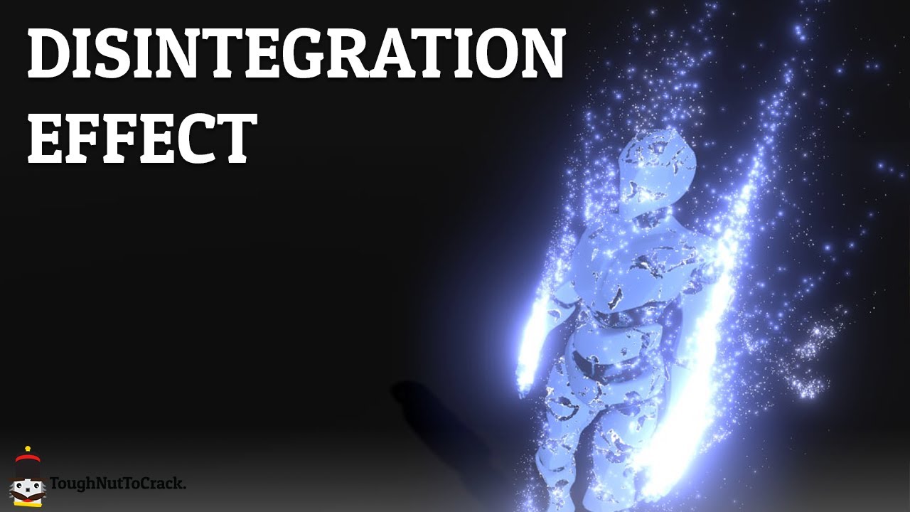
Nowadays, in the video game world, it's not uncommon to find a disintegration effect applied to the body of the fallen enemies.
This kind of effect is also often used to recompose the player when it spawns.
Today we'll recreate this effect on Unity.
MODEL:
https://skfb.ly/6xowz
GITHUB:
https://github.com/ToughNutToCrack/Disintegration
OUR D...
I'm not sure if this is a shader issue or maybe a post processing issue, but I have this problem
reddit
2 votes and 0 comments so far on Reddit
I made a reddit post but didn't get any responses, I thought i'd try here, any help would be appreciated!
You displace in the geometry shader, not the vertex shader
Hi, I'm "cuting" my cylinder inside a shader and reconstructing a normal of the backfaces. So I send the normal and the position of the plane that is cutting the cylinder, and everything works fine. Now I'd like to generate coordinates for the backfaces using projection matrix, but I'm not good enough at math, can someone help me ? ^^

I'm not sure if what I want is clear
Mostly OK.
As you stated, branching on a uniform value lets them all take the same branch, so no divergence. It is done all the time.
It's "bad" when you have divergence an all cores take the time to execute both sides of the branch even when masked off (they share the same program counter).
Asked this before, but does anyone know why my outline shader doesnt work when Exporting to Android (APK and URP)? Instead of being an outlines its basically inside of the gameObject, so when I zoom in on it, the inside is black. This works fine in the editor Image 1 is editor and in the export its well without that outline

None of my shaders work properly actually
I've never done shaders before
how can I use a comparison node for getting in-between two values? I want my shader to do a specific thing between .4 and .5 but don't really know how to make that work with the comparison node


Sounds like you want to create a cylinder on a plane using parallax? Or do you just want double sided faces? Because backface culling can probably be disabled
Or do you want to invert the normals on a shader level?
I actually managed to do what I wanted, I think I was not clear so here is an image to explain, the checker on top of the cylinder seems to be mapped on a plane, though this plane does not exists, I'm constructing it from the positions of the backfaces

And I'm discarding the pixels above that "plane"
How can i show tiling and offset using shader graph? dont want to create separated variables just for this probably there is easy solution like in standard shaders

If you click on your texture2d parameter, in the node settings you can enable "use tiling and offset"

hm maybe wrong shader type created? no option for me

I'm using URP in unity 2021.2.3f1
mine is 2020 ;/
Maybe it was not here yet in 2020
yep, i tried rn in 2021 and its there, fk
@grand jolt theres a node for tiling
i know but the fields are not showing in the inspector
You have to make 2 exposed vec2 properties for that, and link them to the node in the graph
yeah.. just updated to 2021, easier 😛 but thanks
Its super weird they didnt add that earlier
it has been in sgraph since the beginning, you just had to do it with nodes
Of course you could but that sucks
On shader code that works automatically (unless you use [NoScaleOffset] attribute)
Ah I'm a bit late, but thank you for this! Yep we're using spriterenderers mostly, so SRP batching was out of the picture to begin with.. 😅
https://gyazo.com/bb3e8a1cb796106271fb8f3656f2b73a
Does anybody know how to make the sine time go from 1 to 0 just once?

Just once ? When ?
You could send the value to the shader with a script
The time variable continually inscreases so you could do that only once with the shader but it would be right when you open the scene (or at a specific instant dependind of an offset you subtract to the time variable)
Technically the looping wouldn't be an issue if it started dissolving right away. The effect would end by the time it grew back in but that probably aint possible
Thinking that perhaps I should either turn to amplify shadergraph and try custon data or animate it x)
You have to send a variable with a script, and you increase that variable each frame
Hello. I could I ask for help regarding shaders? I'm trying to use a Opacity Maps but every time I use one in my shader, some faces are flipped and are see through.
You can see the issue in the image. -- Could I be doing something wrong?

I'm using this shader from the internet to give my sprites an outline, but when they have the shader they are all translucent, any idea on how to fix?
Anyone?!
Hello ! I was wondering if it was possible to make a shader that replaces certain colors by others and makes them glow. I already did that for giving certain colors a glassy texture (If R and B == 254 then a color is taken from a gradient using G and a glass effect is applied to it) and I would like to do the exact same thing but with glowing in the same shader

this comes from this tileset

Hello guys, currently I have an infinite terrain system that works by tiling terrain chunks/planes next to each other in a grid, I am wanting to shade this terrain (grass etc...), and so am calculating the steepness at a certain point and colouring the terrain based on steepness, however it seems because of the multiple tile approach, things dont lign up...

Any help appreciated, on a single tile it works fine.
maybe fuse the tiles into a single mesh after generation?
just a loose idea, not sure if that's usable in your case
would certainly help with UVs
So I also asked this in #archived-urp however after turning off the Universal Pipleline it still occures. So I have this project where every material is rendered very aqua blue. I do not know why this is, the materials are succesfully compiled.


sure this would be a good idea, but its an infinite terrain, I pool all these tiles and dynamically re-place them around the player.
A good suggestion though, but wouldnt work in my case
post your shader then, maybe we'll figure something out
sure
I think this might be because the cubemap used for ambient lighting was automatically baked while the skybox shader was compiling or something. Try manually baking it from the Lighting window
Will do, thanks for the response!
whats the best way to post code?
Well
there we go
thats the shader
oh, you will need to comment out the line Includes/Math.cginc, not actually using this include right now
doesnt fit
the triple thing
discord wont allow it
oh dear
Tried rebaking it and it didnt change anything :S
message too long
I mean wait, I can get rid of the wasted space and try and paste it
it's fine, i downloaded the shader
ok cool
I dont have the most experience writing shaders, but I like to think that this problem is more related to the fact I am using multiple tiles than the shader code itself

this screenshot maybe shows the seams better
Hmm it should.. Maybe try going into Preferences and clear the GI Cache.
Doing it now!
i don't see anything wrong with the shader, but then again, i'm not some shader wizard
the seams are exactly at the edges of tiles in all cases?
AAAAH YESS OMGGGGG @regal stag you're awesome 🙂
yup, all cases
No worries if you are a bit puzzled also, I think the task is a bit of a weird one.
I could send you a sample displaced mesh if you wanted to test it out for yourself
yeah, sure
What do you think it's the simplest way to randomly pick a channel from a texture in shadergraph ?
alright one sec
Give that a try Festus
Let me know if there are problems with the meshes
might be a bit of a jigsaw puzzle to fit the pieces together
but there are only four pieces so shouldnt be too difficult haha
Is there someone experienced with shaders, that can help me with a few questions for my homework quiz about shaders? 🙂 I'll make it worth your while. PM me
@onyx jungle i don't have math.cginc
Just comment it out
Wait
It’s needed for the blend function
Let me attach it
One sec
There we go
thank you
i have no bloody idea why this happens, since the shader operates on absolute values
            float3 compositeCol = lerp(_ColA, _ColB, steepness);
o.Albedo = compositeCol;```Sure no worries festus
even this produces the edges
Btw, one thing that didn’t produce edges was using the IN.worldPositon and sampling a height value
However I want to change colour based on gradient not height so it doesn’t work for my scenario
so maybe there's something fundamentally wrong with trying to do that using a dot product?
i don't know why would it be, though
Maybe, I don’t know enough about shaders to say for sure
But I appreciate you giving it a try
So thanks regardless for your time 🙂
hope you can figure it out
Cheers

@onyx jungle
The dot product can produce a negative result. Maybe remap it to something that works for your lerp.
GPU dot products range from -1 to 1.
See https://docs.unity3d.com/Packages/com.unity.shadergraph@6.9/manual/Dot-Product-Node.html
Also you may wish to normalize the input vectors if they aren't already.
Hmm, again, I am a little unfamiliar with these terms, I’m not the greatest shader writer, however I did clamp the dot product output between 0 and 1 range for the lerp
input vector is just 0,1,0
i tried remapping instead of clamping just now, and the edges are still there
I'm looking for a way to make something like "if x > 0.4 && x < 0.6" with shadergraph, I just don't really know how to achieve the && part with comparison and branch nodes
There's an And node to combine two bools from the comparison nodes
thanks! sorry for the silly question
@regal stag hello! I'm using a toon shader based on your custom lighting for URP shader graph and trying to improve it's additional lights function by adding ramp texture to it just as you did with the main light
I'm not a shader programmer, so asking you (and other people here) for some help
First screenshot is the main bit i'm working with, where light is from GetAdditionalLight and texture is Ramp Texture
It works kind of fine, but ramp is only applied based on the distance between light source and object (in this case - ground) and doesn't work when changing the range of light source (range only cuts off the whole light)
Any ideas?

The ndotLerped used to sample the texture doesn't take the distance attenuation from the light into account so I think that's why changing the radius doesn't work as you expect.
Could try * light.distanceAttenuation, but unsure if the way they calculate it would be good for sampling a ramp tex. If it doesn't scale well, it might be better to use the GetAdditionalLightDistanceSqrRange function I added to the CustomLighting.hlsl (if you haven't got it in your version see the updated one : https://github.com/Cyanilux/URP_ShaderGraphCustomLighting/blob/main/CustomLighting.hlsl).
Can use that to get the distanceSqr and radius directly, then maybe do something like ndotLerped *= saturate(1 - (sqrt(distanceSqr) / range)) before sampling (though that code is off the top of my head so unsure if it's correct)
(Can probably also do attenuatedLightColor * saturate(NdotL) instead of the LightingLambert() usage, so it doesn't need to do the NdotL calculation twice)
ok, thanks again anyway Festus, weird stuff for sure.
This function worked! Really simple solution, and I actually didn't know you updated your code, it's a really good solution!
Though I had to increase range of my light in two times, but it can be fixed just by using a ramp texture with larger white part

I actually tried to find a way to get the distance and range of additional lights, had a feeling that's the way and good thing that you've already done that function :)
also @regal stag I'm fascinated by your stylised procedural skybox shader, do you still think about making a breakdown or opening source?
Yeah I was thinking about doing a breakdown, started one briefly before the end of the year but haven't got around to continuing it yet
There's a few other stylised proc skybox tutorials out there already too. On mobile so can't really link them but I know MinionsArt and Jannik Boysen has one
I'll definitely check them out tomorrow, thanks, this is really helpful!
I have a shader graph issue, where sprites look fine in scene and game view but come out as bloated in the build.
The first picture is a normal sprite and a shader graph sprites in the scene/game view
The second picture is the same normal and shader graph sprites when it comes out in the build
The third picture is the shader graph used to create the glow effect
I tried to find help here before, on reddit, on youtube comments but couldn't find a solution to my issue
Using the default universal render pipeline and 2d renderer, and other than assigning the scriptable render pipeline, everything in the project settings are on their default
any help would be greatly appreciated


anyone know why this takes so long?
During build, always takes way to long to compile shader variants, i don't have this problem in-editor, only when building


before I start poking with shaders and shadergraphs and stuff, is there a simple way to light 2d objects in HDRP? I just want some glowy stuff
https://gyazo.com/cd06bfd2418002c5d8cd6621489aebef how do i fix these weird bands in my shadow
this only happens when I add shadows to my shading
Pastebin
Pastebin.com is the number one paste tool since 2002. Pastebin is a website where you can store text online for a set period of time.
Im using urp and hlsl
Hdrp is not really a good solution for 2d projects. Urp has 2d renderer with all the 2d lighting features on it so id recommend it instead
why does the water become completely transparent upon using a Contrast node?
Perhaps because it converts the value to a Vector3 rather than a float. I'm not sure if it's the contrast node in particular that is the problem though, might be something later down the line?
hmmmm
If the emission texture is transparent you might want to use the A channel rather than R. Maybe also Saturate/Clamp after the Add to prevent values going above 1.
Could also check the texture settings (e.g. disable mipmaps, make sure texture size isn't being rescaled due to max scale, try adjusting compression, etc)
Could try rendering the circles/viewRanges additively (Blend One One) to a Render Texture (via a second camera) as fully opaque then draw that texture then with lower opacity before everything else on the main camera. Though another camera & buffer might not be great for performace/memory.
Could also try looking into Stencils (but it can't do any partial transparency). https://docs.unity3d.com/Manual/SL-Stencil.html
e.g. Render each viewRange also to the stencil buffer while testing for NotEqual comparison. (so if the value is already in the buffer, the pixel is discarded, removing the overlap)
Stencil {
Ref 1
Comp NotEqual
Pass Replace
}
Or another method is to render all the viewRanges into the stencil buffer only (ZWrite Off, ColorMask 0) and then draw a fullscreen quad testing against it with Comp Equal to colour it all at once.
Can anyone help me with some shader questions?
oh also @regal stag I get this error now for some reason
it's everywhere where I use custom lighting but it doesn't affect the resulting shader and everything looks and compiles ok
it's just appearing in the shader graph editor and messes up previews
Should put the GetAdditionalLightDistanceSqrRange function you added inbetween #ifndef SHADERGRAPH_PREVIEW #endif. It's because it uses other functions (GetPerObjectLightIndex) that are specific to URP and ShaderGraph wont include those for previews.
Oh! So that's what it's for! Thank you
are the Simple Noise and Gradient Noise in Shader Graph not seamless at all?
or are they?
They generate continous noise along their coordinates, but if you are repeating a particular section it will produce seams.
Maybe, What do you need the noise to do?
If you're trying to make the noise connect seamlessly across multiple objects you can project the noise using planar mapping e.g. using XZ of Position node in World space, but that's only going to work on mostly flat surfaces, will stretch on vertical ones.
so i can google how to fix it, what's it called when a model moving around leaves impressions? think of like winxp when you'd drag a window around while it was processing

Not sure if there's a particular name for it, but it usually happens when the render target / camera is set to not clear.
im trying to do a waterfall vertex displacement
and the seam is screwing my waterfall mesh
I see, the seam probably comes from the model's uvs then
hmmm
this is how my waterfall mesh UV looks like

huh, i took a stab in the dark and changed these from pipeline to on and everything fixed itself
thanks cyan for pointing me in the right direction!

Not sure if you should enable those if you aren't using them really. It's a little weird that it doesn't clear without them though 🤔
I assume the seam is on the side then. You could make the back side of the waterfall's uvs overlap with the front (but still mirrored, or like a projection from the front)
alright will give it a shot
It will mean the noise is the same on both sides too but that's probably not that bad
yeah i've got a lot of weird glitches in unity, tried three different versions of it and a lot of shaders and unity UI is bugged but eh, i'd rather used a cursed version of unity than a fully functioning version of unreal
oh wait nvm the displacement strength was just too high
problem solved, thanks cyan 👍
why does the noise go black when i increase the speed of it??
Hello. I have this weird texture flicker when changing the position or orientation of the camera, relative to the object. I am using a custom diffuse shader that is half-Lambertian. Not every object with the shader flickers. It seems the larger the object, the more likely it is to happen. Tried restarting, using full lambert, fiddling with the far/near clip planes, avoiding intersections with other objects, and none of it has stopped the flicker. Googling hasn't helped much either. Would be grateful for any insight on what could be going on.
Say you have 2 rings in blender, one large and a smaller one inside of the large one, can you automatically fill the space between the 2 rings without filling the hole in the smaller ring?
It looks like the flicker occurs when multiple objects using the same material are on screen, so possibly related to batching.
Not really a shader question, but I think what you want is to use "bridge edge loops"
Oh I meant to post this in art-asset-workflow you're absolutely right @regal stag
investigating bridge edge loops, thank you
If you've had Unity open for a while the Time value might be fairly large, which causes the generated noise to break down. It's one of the downsides to something generated rather than using a scrolling texture.
Trying to make a skybox gradient color
So what I wanted to do is to make the horizon edge a bit sharper, and to do this I thought of regular multiplying. When I'm multiplying "Time" for Lerp by an amount higher than 3, colors go crazy. Two colors are light blue and darker blue, but there's literally no green so it's weird for me...
What is that?

I might be wrong with the usage of time but I have no idea on that
There's negative values in your T input which results in the green. Can use a Saturate to clamp between 0 and 1 and it'll remove it.
Right! This works

I'd do the Saturate after the multiply as you probably also don't want values above 1.
got it!
ah i see i see
Word. I'm reading into it. This appears to have been the issue. Thanks!
How can I make it so that the sun isn't visible through clouds?
In shader graph: sun is added to sky, and sky is lerped with clouds by a cloud mask on the horizon (to put it simply - clouds are added to the sky)

Okay, Im new to shaders and am trying to pick up ShaderGraph. Today I opened up my mostly empty project (URP) and my white shader was now blue. creating a new lit shader and the white is still blue. this was not happening before and doesn't happen on a new unlit shadergraph. how do I fix and avoid this issue?
Is everything tinted blue (light blue / cyan?) or just this shader?
it could be something up with ambient lighting
yeah everything has a cyan tint
As long as the sun is added before the lerp with the cloud mask it shouldn't show over the clouds.
I'm noticing this isn't happening in URP's sample scene
Then yeah, it's a bug that I think is caused by shaders compiling (which show as cyan) when baking lighting/GI. I think the bug is meant to be fixed but still seen a few others with the problem. Could try updating Unity/URP, but otherwise you should be able to fix it by going to Preferences -> GI Cache, and clear the cache. Then rebake lighting via the Lighting window (might also rebake automatically anyway).
clearing GI cache worked, thank you for the help and explanation 🙏
The sun is added before but it's still visible through clouds, possibly because they become a little bit transparent after lerp?
I'm using clouds Jannik Boysen made, which looks like this. If I made a guess, this remap part on top makes it kinda transparent?

Where does the Remap go into?
Top is sun + sky, remap is the second value and time is the mask (just colored with float3 color)

oh nvm it's actually float4
but alpha is 100% all the time
Okay the problem is probably the Multiply with CloudColor, you should do that on the B input after the Remap, not on the T input.
oh this actually worked
I thought that way the color won't be applied to the part where mask is but it works anyways

Can someone explain me how I'm using transformation matrices wrong? Here's the simples thing ever
v2f vert (appdata v)
{
  v2f o;

  o.vertex = mul(v.vertex, _LocalToWorldMatrix);
  o.vertex = TransformObjectToHClip(o.vertex);

  return o;
}
_LocalToWorldMatrix is a float4x4 and I set it from script using transform.localToWorldMatrix
Rotation is inversed and translation does not work... Literally why
This is a HLSLPROGRAM if it makes any difference
This mesh is also drawn as instanced indirect hence the matrix I pass
I think the inputs are reversed. Have you tried mul(_LocalToWorldMatrix, v.vertex)?
Might also need to do float4(v.vertex.xyz, 1); for the second parameter to get translation to work.
💀
That was kinda embarassing but wasn't it always left to right??
It works now
I guess it's a hlsl thing
@regal stag thanks
It is left to right. Thats just how matrix multiplication works ig
I should really dedicate some time to learn proper math huh
Left to right as in you multiply a pont (left) by matrix (right)?
You just gotta remember putting matrix first and then then vector
Matrix goes (usually) always first
It would be more intuitive to give vector first but thats not correct
Probably just matters on the format of the matrix. If it were transposed I think the other way around would then work. But in Unity it's usually matrix first.
I guess the order is kinda similar to how rotating a vector by a quaterion in C# is Quaternion * Vector.
One of these things to just remember then
Now that I think about it inversed rotation was probably a big clue to try and swap these two lol
Has anybody here controlled shaders though custom data here? Mine doesn't seem to work, or is there a big difference on which channel goes where? For now I just tried looking on which one doesnt screw up the current effect

The custom data is going into TEXCOORD1.xyzw (according to your custom vertex streams list) so should be using UV1 channel on the UV node. R on the split should correspond to the curve you've set.
Not sure why there's the error about streams not matching though (might go away if you start using UV1 and save the graph?)
Anyone know how to make the texture of Sample Texture 2D very clear, because when i put it on an object its pretty pixelated up close
I use a png file for the texture but i heard of another way
It won't clamp no. If floating point errors are a problem you'd probably need to use a float property instead and have control over if from a C# script.
When saying UV1 channel, do you mean I should delete the UV2 and only keep the UV? As there's only TEXCOORD0.xyzw and TEXCOORD2.xyzw
Quoting myself from #archived-code-advanced since this channel may have people with the relevant experience:
Does anyone here know of a viable GPU hardware occlusion query implementation?
I'm looking at
GPU Instancerbut that seems to only support Hierarchical-Z for instanced objects, and I'm aiming to have complex one-off geometry occluded by it without baking.
I mean that the CustomData "Custom1.xyzw" is assigned to "(TEXCOORD1.xyzw)" on the particle component under the custom vertex streams in your screenshot. So if you want to get those values in Shader Graph, you would use the UV node, but change the Channel on the node to UV1 (TEXCOORD == UV in Shader Graph).
While using a UV node with channel set to UV0 would mean the (R,G) of the vector corresponds to the UV (TEXCOORD0.xy) and the (B, A) of the vector is the UV2 (TEXCOORD0.zw). Can Split and put it into a Vector2 if you need that. Hopefully that makes sense.
Ohh I completely missed the channel section on the UV node.. Thank you for the patience when explaining in detail
So now that the channel is UV1, the shader is painfully sensitive to numbers, which wasnt the case before. Are there any values that could be overlapping with something?
https://gyazo.com/11443fbe1e7872643753a2cec26407f4

Eh not sure. That goes into the B in the Power node so maybe it just doesn't like negative values?
That makes the material fill up completely even in the preview x)
So is it okay that when the channel is UV1 but UV and UV2 in the Custom Vertex Stream are assigned to TEXCOORD0.xy and TEXCOORD0.zw?
Yeah should be fine. The "UV" and UV2" are kinda just names for those coordinates. They can be packed into any TEXCOORD/UV channel. It would probably also be a little less confusing if Shader Graph used TEXCOORD instead of also labelling it as UV. 🤷
The C# Mesh class is just as bad. They use .uv .uv2 .uv3 which doesn't really line up with the shader side (TEXCOORD0, 1 and 2) 😛 (There is Mesh.SetUVs instead which does use a index starting from 0 though at least)
It was the mip maps, thank you so much!
Did you end up having to disable the mipmaps, or did you add an alpha channel to them?
the emission texture was pure white with pure black background so i used a color channel instead of the alpha channel, it was the mip maps that were changing how the sprites looked in the build view, i just had to disable it in the sprite settings
i guess they generate mipmaps by default
also today i learned what mip maps are and that they existed in the first place XD
always learning o/
THIS, it's called texcoord in every shader graph ever except here >.> Makes me want to transfer to aplify a little more everyday
There is no support for it in the command buffer API itself so you're unlikely to find any. You might be able to make one by writing a native rendering plugin but I'm not sure how it'd work.
Ouch - you seem to know what "it" is that is missing- do you have a name for what it is that I'd need to make to compensate, so I can use that when looking up resources?
In other words- what functionality do you expect would be needed from CommandBuffer that isn't there?
It also looks from the documentation like CommandBuffer isn't used in HDRP or URP- unless I'm misunderstanding something
@gentle crow uhm no, all of SRPs is built upon command buffers.
Predication queries have their own API calls that aren't exposed in Unity at all.
The D3D12PredicationQueries sample demonstrates occlusion culling using DirectX 12 query heaps and predication. The walkthrough describes the additional code needed to extend the HelloConstBuffer sample to handle predication queries.
See here.
Hmm - that looks like it allows fully on-gpu occlusion, while I'm looking for something akin to Hi-Z
Need to insert query commands into the command list.
(Am I understanding correctly that Predication implies essentially "on-gpu logic switching based on a predicate"?)
🤷♀️ But this type of occlusion testing is called hardware occlusion queries.
I believe there's a few ways of doing that; the one I am hoping is possible with current pipelines is closer to "dispatch a list of positions and sizes, then asynchronously get back a list of which ones were visible a few frames later"
the CPU organizes what to show/hide based on those results, and that separation of handling causes frame asynchrony and potential artifacting. Hardware predication seems to be intended to reduce or even resolve that.
Well, you will have to code Hi-Z yourself. Cause occlusion queries aren't available.
VK_EXT_conditional_rendering appears to provide this capability portably, for what it's worth, but...
can i use shaders to go from the first image to the last?


That looks like cylindrical projection. If you search that term with "shader", you might find some resources
i tried to recreate the effect using a post-processing lens distortion, but i doesn't really seem to match up that well. also i did find a shader that has the desired effect but i am not familiar enough with unity to implement it
not sure if you can help me with that
I'm trying to find away to make my Lighting.hlsl support point lights/multiple lights. This the shader code:
#ifndef CUSTOM_LIGHTING_INCLUDED
#define CUSTOM_LIGHTING_INCLUDED

void CalculateMainLight_float(out float3 Direction, out float3 Color) {
#if defined(SHADERGRAPH_PREVIEW)
    Direction = half3(0.5, 0.5, 0);
    Color = 1;
#else
    Light light = GetMainLight();
    Direction = light.direction;
    Color = light.color;
#endif
}

#endif
I've tried looking at some other .hlsl files used for the same thing but those ones often are much less simplistic (and I really don't need all of that other stuff for what I'm trying to do)
you need to grab the additional lights amount with GetAdditionalLightsCountand loop over them
 int pixelLightCount = GetAdditionalLightsCount();
        for (int j = 0; j < pixelLightCount; ++j) {
            Light aLight = GetAdditionalLight(j, WorldPos);
            // grab direction and colors
}
Thank you! That worked!
if i want to edit a property of a material of just one gameobject, do i create a script for it and reference the material(not sharedMaterial) of the Mesh Renderer ?
Yeah, using renderer.material will create a clone/instance and automatically assign it to the renderer for you. You should also destroy the material instance when you are done with it (e.g. in OnDestroy() method)
For the built-in RP there's also Material Property Blocks that can be used instead. But for SRPs that breaks the SRP batcher.
Anyone know if we can change the target shader model of shadergraph? I'm trying to use a StructuredBuffer but it won't allow it (presumably because it's pre-SM5.0)
alright
but the thing is, how do i edit the property values without going into play mode?
anyone wants to save me some headaches and give me a shader graph that is similar to the default URP/Lit shader?
I'm trying to replicate it so that i can use it with virtual textures
Might change depending on pipeline but in URP the last time I checked it generates two SubShaders, one with target 4.5 (which should still support compute buffers according to https://docs.unity3d.com/Manual/SL-ShaderCompileTargets.html) and another with target 2.0 (I think for gles platforms?).
I've had StructuredBuffer working in a custom function (file mode) without needing to do anything else, but if you're getting errors, might be able to have #pragma target or #pragma require compute in another custom function (usually string mode works better as that gets pasted directly into the generated code rather than as an include file).
You mean a shader that is similar? The shadergraph already comes with the default URP lit
I don't have any other custom functions sadly, and if I put "#pragma target 5.0" or "#pragma require compute" it throws warnings about unknown pragmas
that's pretty much what i need, but where is it?
Oh I think I see what you mean... Like how the URP lit has inputs for height / occlusion etc.?
yeah.. detail albedo and detail normal maps too if it was possible
I believe that's some kind of custom inspector, and not possible within shadergraph
Grain of salt
🥲
You can reconstruct a less versatile version of it pretty easily since most of those nodes attach to the master directly
fair enough
Unless my shadergraph is some kind of old version?
but im too bad at this...
For edit mode I'd usually just stick to creating material assets manually. But you could use [ExecuteInEditMode] (https://docs.unity3d.com/ScriptReference/ExecuteInEditMode.html) to have the script work during edit mode too. You just need to be careful about leaking unused material instances or you'll slow down your editor, and use DestroyImmediate instead.
What version of Shadergraph are you using? The only milestone version after 12.1.2 is 13.x on 2022
When I last did experiments with StructuredBuffer it was back in v10. I guess it's possible newer versions have broken it.
"stick to creating material assets manually", what's material assets?
Like, how you'd usually create materials, in the project window.
ahh i see
do i have to make a custom inspector though if i were to create an entire script dedicated to edit the material?
Would probably be a bunch of public fields which would make them appear on the component. Doesn't necessarily need to be a custom editor/inspector unless you want to organise it in a particular way.
alright thankss
Can anyone tell what's wrong with my depth fade? It completely ignores the floor and the mountains that are definitely not touching the mesh 🤔

You should be using Eye sampling mode on the Scene Depth node and Raw mode on the Screen Position.
Oh that's it? :^)
Many thanks
How exactly do you add vertex displacement maps to a material?
The standard URP Shaders only seem to have height maps
You need to use your own shader
can I just make a simple displacement material and slap it on the mesh I want, or do I need to remake the whole standard shader but also include the vertex stuff
Simple
How do I change this to affect the whole object instead of the pixels

Hmm, Instead of using Screen Position node, use the Object node and put the Position output through a Transform (World to View space). (Or I guess just using (0,0,0) and Object to View space also works)
Then Split, take the Z/B axis and Negate it.
hiya, I tried following a guide to make a dither-fade effect based on camera distance

this works great except i'm trying to use screen position instead of camera distance to ensure that objects fade about the same time in front of the screen, right now objects slightly closer to the camera fade sooner

here's my attempt to use screen position. the problem is that objects don't seem to cast shadows anymore?


weirdly, if i flip ditherStart and ditherEnd so that objects further from the camera will fade, it does cast shadows, but the shadows seem to be unaffected by the dither effect and continue to show even after the object has disappeared

pretty new to shadergraph so admittedly i have no idea what's going on here
Hmm. Don't know if this will fix it but I am curious, If you swap the Screen Position out for the Position node, set to View space, Split and Negate the Z/B axis, does that cast shadows then (or act the same?)
let me give it a try 👍
Thank you!
why is one face not fading like the others?

It should now fade based on the object's origin, so maybe it's origin is further away compared to the other objects?
Static batching would probably also move the origin to the world center (0,0,0) since it combines multiple renderers, so make sure the object isn't using that
it seems to have the opposite problem now 😂 being nearer to the camera fades the object, but shadows persist after the object has faded

additionally, flipping ditherstart and end again so that objects further from the camera are faded now don't cast shadows

i just wish i understood why this doesnt happen when using camera position. thanks for helping btw! didnt occur to me to try using view/world position, i have some more things to fiddle with
How do I do geometry shader instancing in Unity ? I'm not talking about normal instancing, i'm talking about having n invocation of a geometry shader
Anyone know why my shaders dont run in URP?
they work fine in the editor
but as soon as I build it to android, they break
2019.4 LTS building for VR Quest btw
Don't know for sure, but my guess would be that the Position from the Camera node uses _WorldSpaceCameraPos, which is always based on the camera that is rendering (the actual camera). But when rendering the realtime shadowmap Unity is likely overriding the view and projection matrices.
And pretty sure the shadowmaps use an orthographic projection, which means the W component of the Screen Position (raw) will actually just equal 1. In perspective projections (like your camera) it's the viewspace depth, hence why I suggested using the Position node in view space directly. But if the view matrix is also different the z values won't be the same for both passes, so no dither in shadows.
I think there may be a camera view matrix that doesn't get overridden, (I'll see if I can find what it is). But otherwise could probably also try setting up a global matrix property in a C# script and set it to cam.worldToCameraMatrix. (That method won't work if you have multiple cameras rendering though, unless you change the matrix before each one renders)
oh huh
thats really helpful and ill look into it more, thanks!
Been having this for weeks
I think it might be the unity_WorldToCamera matrix so could try doing Out = mul(unity_WorldToCamera, float4(positionWS.xyz, 1)); in a Custom Function node (with Position node in World space as input).
Im using a Unlit shader, could that be the issue?
I assume you're referring to this? https://docs.microsoft.com/en-us/windows/win32/direct3dhlsl/overviews-direct3d-11-hlsl-gs-instance
I've never seen it be used in any tutorials (didn't even know it existed) so unsure if it works in Unity, but you could try following what they list there and see. It's in shader model 5 so will likely need #pragma target 5.0 too.
It's kinda hard to tell without seeing a shader. If you're using shader code, there is a few differences between built-in and URP shaders (though unsure which parts would be required to make it work in a build). It's usually easier to use shader graph but I also have an article : https://www.cyanilux.com/tutorials/urp-shader-code/
The URP docs also have a few bits : https://docs.unity3d.com/Packages/com.unity.render-pipelines.universal@12.0/manual/writing-custom-shaders-urp.html
Its a custom shader, but I was able to figure it out with the shader graph, thanks anyways :)
Custom meaning a coded shader
Hi, I'm trying to mark an object's position on a skybox by setting a _body_position property on the material, but I don't know how to determine the vector to that object or how to make the skybox render a fresnel around the object. Here's a screenshot of my current graph, you can see the fresnel is only on the z axis. How do I center it on the given object position?

basically I spent 2 hours making a custom shader while this made it in 1 minute https://www.youtube.com/watch?v=s_P3dVZvVxY

Bytesize Gamedev is a series of videos featuring tiny effects, delivered in 60 seconds or less. In this video, learn how to make an outline effect in Shader Graph and URP.
This video was previously posted on Twitter: https://twitter.com/daniel_ilett/status/1313815235103518723
Unity 2019.4.12f1, URP/Shader Graph 7.3.1
-------------...
👁️ 👄 👁️
I think you want to use a Dot Product between the vectors to the object position & skybox position
I will try that, thanks!
Oof yeah, I guess it works but I really don't like the double-sided rendering then clipping the front faces away.
Unity actually has a inverted-hull outline shader code example for URP here you could try : https://github.com/Unity-Technologies/UniversalRenderingExamples/blob/master/Assets/_CompletedDemos/ToonOutlinePostprocessCompleted/Shaders/ToonBasicOutline.shader
It turned the whole sky gray,
What is wrong with the 1st one?
It's almost working except for this error <RI.Hid> Failed to create device file
I tried googling but that error sounds like it's related to input (like keyboard/controllers) not shaders.
Can you show the graph?
ok it's working, i just had a random bug for no apparent reason
Hey, so my shader graph broke again for some reason and this seems to look better, however I wasnt able to import it properly...
I feel like I picked the wrong one, however I have no idea which one I would pick

It's just that Shader Graph doesn't allow you to just cull front faces (that may have changed in newer versions though, can't remember). There is some cost to rendering both sides and alpha clipping the front away though, while the shader code version just uses Cull Front.
It didnt work anyways haha
Shouldn't really matter, as long as it's a .shader file you're likely going to replace the entire contents anyway.
Shader "Outlines/BackFaceOutlines"
{
    Properties
    {
        _Thickness("Thickness", Float) = 1 // The amount to extrude the outline mesh
        _Color("Color", Color) = (1, 1, 1, 1)
    }
    SubShader
    {
        Tags { "RenderType" = "Opaque" "RenderPipeline" = "UniversalPipeline" }


        Pass
        {
            Name "Outlines"
           Cull Front

           HLSLPROGRAM

           #pragma prefer_hlslcc gles
           #pragma exclude_renderers d3d11_9x

           #pragma vertex Vertex
           #pragma fragment Fragment

           #include "BackFaceOutlines.hlsl"

            ENDHLSL
        }
    }
}
``` I did this beforeIt worked fine in the editor, just not in the build
#ifndef BACKFACEOUTLINES_INCLUDED
#define BACKFACEOUTLINES_INCLUDED

#include "Packages/com.unity.render-pipelines.universal/ShaderLibrary/Core.hlsl"

struct Attributes
{
    float4 positionOS       :POSITION;
    float3 normalOS        :normal;

};

struct VertexOutput
{
    float4 positionCS      :SV_POSITION;
};

float _Thickness;
float4 _Color;

VertexOutput Vertex(Attributes input)
{
    VertexOutput output = (VertexOutput)0;

    float3 normalOS = input.normalOS;
    float3 posOS = input.positionOS.xyz + normalOS * _Thickness;
    output.positionCS = GetVertexPositionInputs(posOS).positionCS;

    return output;
}

float4 Fragment(VertexOutput input)    : SV_Target
{
    return _Color;
}

#endif
I'm new to the graph so the math isn't really intuitive for me yet.

Alright so small issue with the one you sent me hehe

Not sure if I like the :normal; being in lower case but I don't know if the semantics are case sensitive though.
Ideally you should also have the _Thickness and _Color properties in a cbuffer like Unity's example is (in order to support the SRP Batcher)
I scrapped that one anyways, since it gave me too many errors but I just wanted to show what I had before trying the unity one out (Which also seemed to break)
I dont really do shaders so ye haha
Try putting the Dot Product output directly into the Color on the master node , save and see what it gives you in scene view. It should basically make half of the skybox a gradient, pointed in the direction of the planet.
If it does that, you should then be able to remap it a bit with something like a Smoothstep node
Instead of doing outlines, it seems to be deleting the face I'm looking at and completely do the inside instead
That's basically what the technique does, yes. You can assign multiple materials to the MeshRenderer so that you still render the inside with a different material.
(or alternatively, use the RenderObjects feature to draw outlines on all renderers on a particular layer)
It turned the whole sky gray. I did exactly as you said, same graph, just put an add node between dot and color
okay, so right now I have my cactus material which is just pure green, then I also have my outlines material and my shader... how exactly do I "Assign multiple materials to the meshrenderer"?
@regal stag, thanks and respecc for multitasking
Click on the object, in the Inspector there should be a MeshRenderer component. Click the + to add another material to the array. Drag a material into the new element.
Like this. It might show a warning but that's more for the built-in RP.

ah thanks
Not sure where to go from here
I thought I would need a 3dimensional output to have something centered around a position, but dot is only 1
Okay so this is for an atmosphere around the planet? Is there a particular reason why you need this on the skybox rather than just using a sphere mesh to surround it? That way you probably have more control over the position.
Or I guess a sphere mesh with faces inverted
I have noticed sphere meshes in other planet atmosphere's in games and I'm just trying to get a quick and dirty shader that still transitions smoothly
Hey, so I was playing around with said shader, and I noticed that it was never smooth, no matter what I set the outline value to

Now this wouldnt be an issue if this didnt happen

The outline technique the shader uses only really works for models with smooth normals
ah....
So what would I do instead? I really do want to get these outlines working haha
Anyone know of a way to have per-particle motion blur using the default particle system? The "per object motion vectors" option only seem to blur the particles based on movement of the particle systems transform. Open to ideas. Using HDRP.
Not sure using the skybox is really that quick and dirty. I'd say a mesh is probably quicker tbh.
I was thinking something along the lines of this but the dot doesn't resize to fit the object
(The pos is set to (1,1,-7) in the property settings so previews look nicer)

Maybe export the model itself with the inverted hull baked in
...what?
The way that method works is the model is duplicated, the faces are flipped, and the flipped faces are extruded out from the model (and colored black)
It's called the inverted hull method
You can also just bake the hull into the model itself
ah okay, so how would I do tha tin blender?
Quick google throws up this method:
https://www.youtube.com/watch?v=2k-YdMnqWUU
thank you
But in your case I assume you'd need to create the hull from a smoothed normals version of your model, then split the normals on the main model
So I'm not sure if that method would work
I'll try it out
You can also use screen-space outlines using per-pixel depth & normal discontinuities but they tend to suck
The downside to manually modelling the inverted-hull is you can't easily resize it in Unity but yeah that works.
Assuming you still need the flat normals for shading another method would be to calculate the smooth normal vectors and store it in an unused UV channel or vertex colours, and use that input in the shader instead of the normal.
object position in skybox graph
It looks great, however sadly the black isnt really black if you know what I mean

Seems more grayish
I'd guess it's still interacting with light
No light in my scene
Blender emulates ambient light, no?
The colour in blender probably isn't as important. Can always change the material in Unity
No idea, I'll just put it in unity and see how it is
Not sure how people normally implement it but I think the hull itself needs to be unlit
I cant access the material in unity

stuck on something simple but I can't figure it out. I want to use the FX/Glass/Stained BumpDistort shader with a 2D image to make it looks like there's a semi-transparent splat of goo on the camera. how should I do this?
I tried doing this using a quad w/ a material that has the shader set and the splat image as the texture, but it appears as a giant square for some reason (as shown on the right in the image)

I had to switch the subtract inputs to get the right position, now I'm ready to start coloring. Thanks for the help!
I meant more like create a new material and replace it on the renderer. I mostly prefer that workflow rather than using the materials automatically created from models.
Is there a way to wait for a compute shader to finish it's tasks?
And is it a good design to try and do this?
Tbh I could really use some feedback on the way I use compute shaders, because I don't think I'm doing it right
Basically I have multiple compute buffers and I need to modify them all using a compute shader. Like process buffer 1 -> process buffer 2 -> process buffer 3
I can dispatch multiple times, however because I set said buffer with .SetBuffer and then dispatch in a loop the shader only processes the last buffer
Would I be better off changing the entire structure and using one big buffer instead? I will need to resize it somehow though
What could cause this number of variants?

In shader graph, is there any difference at all from a performance standpoint between re-using an exposed property node or simply duplicating it? e.g. say I expose a float named foo. foo is hooked into 2 different nodes VS putting foo twice on the board, each hooked into a node
https://roystan.net/articles/toon-shader.html
I'm just following along this tutorial while trying to convert it to a URP workflow, I'm a bit stuck at
float3 normal = normalize(i.worldNormal);
float NdotL = dot(_WorldSpaceLightPos0, normal);

…

// Modify the existing return line.
return _Color * sample * NdotL;```

I'm a bit new to shaders but I thought maybe this could work:

```float4 frag(VertexOutput i): SV_Target
{
  Light mainLight = GetMainLight();
  float3 normal = normalize(i.worldNormal);
  float NdotL = dot(mainLight.direction,normal);

  return _Color*NdotL;
}```

I would have thought ```GetMainLight().direction``` would have been equel to using ```_WorldSpaceLightPos0``` but I just get a black circle instead of a basic shadow.
Learn to write a toon shader for Unity engine with specular reflections, rim lighting and shadow casting.
It'll generate the same shader code either way
thank you @regal stag
Code looks equivalent to me. What exactly do you mean by "just get a black circle instead of a basic shadow"
The result is meant to be a lambert. But in my viewport I just get a black circle. Not sure if I'm missing something else for URP to work. If I don't multiply by NdotL the colour output is fine.


How are you calculating i.worldNormal?
Ah, thanks, good catch. I was doing a lot of deleting and editing when I was learning about URP from another article. Completely forgot to convert it.
I was trying to recreate this setup on blender, I think I got it, position or location seemed the good one, but normal seems to match the tutorial


Hi, I recently followed this tutorial by brackeys for a dissolving shader: https://www.youtube.com/watch?v=taMp1g1pBeE&ab_channel=Brackeys

Let’s learn how to create one of my favourite effects: Dissolve!
Check out Skillshare: http://skl.sh/brackeys6
● Download the project: https://github.com/Brackeys/Shader-Graph-Tutorials
♥ Support Brackeys on Patreon: http://patreon.com/brackeys/
····················································································
♥ Subscribe...
Only thing is, the shader keeps looping the dissolve and I dont want it to do that
Is there any way I can make it so when a game object is enabled, the dissolve in effect is played and when its disabled the dissolve out effect plays
Hey, I am trying to make my billboard sprite shader scale the generated colors by the distance from the camera like a sun flare. Here is my graph, I don't know where to go from here:

Is there a simple way to do shadow catching in URP with an unlit shader? I'm just finishing trying to convert this tutorial: https://roystan.net/articles/toon-shader.html - but I'm missing on how URP does shadow catching I think. I figured out the alternatives to things like shadow coord and what not (I think) but I'm not exactly sure how to get the correct data? Hope pastebin links are fine: https://pastebin.com/DqYrM1pJ - probably easier to read it than me doing code snippets.
Learn to write a toon shader for Unity engine with specular reflections, rim lighting and shadow casting.
Pastebin
Pastebin.com is the number one paste tool since 2002. Pastebin is a website where you can store text online for a set period of time.
Anyone know if the "z" (sorting) coordinate of a tile in a tilemap is somehow accessible?
I can't seem to get it via the position or the transformation matrix...
Usually something like
// Main Light & Shadows
float4 shadowCoord = TransformWorldToShadowCoord(IN.positionWS.xyz);
Light mainLight = GetMainLight(shadowCoord);
half3 attenuatedLightColor = mainLight.color * (mainLight.distanceAttenuation * mainLight.shadowAttenuation);
...
half3 shading = LightingLambert(attenuatedLightColor, mainLight.direction, IN.normalWS);
// aka attenuatedLightColor * saturate(nDotL)
But you also need the appropiate keywords :
#pragma multi_compile _ _MAIN_LIGHT_SHADOWS
#pragma multi_compile _ _MAIN_LIGHT_SHADOWS_CASCADE
// Note, v11 changes this to :
// #pragma multi_compile _ _MAIN_LIGHT_SHADOWS _MAIN_LIGHT_SHADOWS_CASCADE _MAIN_LIGHT_SHADOWS_SCREEN

#pragma multi_compile _ _SHADOWS_SOFT
Can also move the shadowCoord calc to the vertex shader if not using cascades. (Shadows.hlsl sets up a REQUIRES_VERTEX_SHADOW_COORD_INTERPOLATOR define you can #ifdef against)
If it helps, I also have some templates here : https://github.com/Cyanilux/URP_ShaderCodeTemplates (DiffuseLit is closest to this, the PBR and SimpleLit use the methods in Lighting.hlsl which handle shading for us so might be less helpful)
Swap the Time node out for a Float Property (set up in blackboard, be sure to set it's reference to something readable - different from the name). From C# you can then set that property via material.SetFloat to have full control over it. e.g. set it to a variable which increases by += Time.deltaTime each frame (Update) and enable the script when you want that to start.
Hey gorgeous people, so im having a weird issue where my water shows properly in the VIEWER, but ingame its just gray

Does anyone have ANY idea what it might be? Using URP
scale billboard with view distance
Ah okay, I didn't have the correct keywords for my shader to work. Thanks! - I've been using your site religiously to help me figure out URP! There were just too many keywords.
Hey folks! I want to let the ground glow from beneath the water and so far everything is good. both components work, but the water surface seems to block the emission from below. If I go into the water with the camera I still see the glow, so it should be something with the surface. Can you support me finding the right direction? Thank you for your time!
It's URP on 2020.3 and water is an unlit shader while the glow is a lit shader, might this be the issue?


How are you rendering the glow? Is it on the shader that draws the grey cube too, or as a second transparent material perhaps?
it's a second transparent map on the cube
one base material with the base map and one material with the glow shader on it
Then yeah, it's not going to appear in the Scene Color node that the water uses. It uses the Opaque Texture (captured after rendering opaques + skybox). Transparents won't appear in it.
Might be able to change the render queue to make the glow render after the water though
Oh, thanks for clarifying! Would it also be possible to get the transparency into the Scene Color? I'll try playing around with the render queue, thanks for the suggestion!
Works! Thanks a bunch 🙏 🙏
right now my waterfall refracts anything that is behind it, how do i refract the texture of the water ripple as well?
making the Render Queue of the waterfall 3001 and the Render Queue of the water ripple 3000 just cause the water ripple to disappear behind the waterfall
as seen here

So how do you implement shadows when using Shader Graph?
Hey, my issue is in #928876040678436884 if anyone has a minute
I am currently working on a custom glass shader, specifically the refraction part. It works good, it refracts everything that is visible on the other side, however, the only thing it doesn't show is any materials that have their Surface Type set to Transparent. What nodes can I use to "capture" all Transparent materials that are rendered on the screen?
Note the cube on right is "Transparent" and just emissive. The cube in center is Opaque. The items on the left use the same shader I'm working on.

Here is my refraction setup.

Is there a way to make the entire triangles have the same have the same specular color?

@regal stag
Is there a way to customize the shadows? Say I want the shadow to be a different color for a particular shader (or materials that use that shader)
probably the best way is to set up custom lighting where you can control such things as shadows by yourself
cyan actually has a good custom lighting sub-graphs to work with

GitHub
Some custom lighting functions/sub-graphs for Shader Graph, Universal Render Pipeline - GitHub - Cyanilux/URP_ShaderGraphCustomLighting: Some custom lighting functions/sub-graphs for Shader Graph, ...
So for instance, if I want my "glass" to have a lighter shadow as if light is passing through, like a magnifying effect. Is that possible?
I am using HDRP
I dont think its possible on hdrp
yee
but talking about glass there's probably a way for that
I'm sure there is, I just need to get a general direction of where I would control this.
bump 🙂
you can try to set up something like this in shader graph, where "ramp" is a simple texture like one I attached

Thanks!
it's a simple method I've got from Cyan's lighting
would step also work?
yeah but I think it's better to set up step before using ramp textures
personally don't use it rn so i'm not sure
I have a very similar question to this, I want faces to be shaded evenly with step-shading, instead of partially shading it with 2 different shades

you want to make it like that? make shadows into one step?


I mean, if these are the faces, not have any face with two different shades on it

ohh
your mesh should be shaded flat, with disabled normal smoothing
i'm not sure how to do this directly in unity, but you can use blender for that
that's the way I do this at least
bump 🍺
nvm I just found it in unity
in mesh import settings set up normals to calculate, smoothness source to from angle and smoothing angle is 0
might work

Didn't work unfortunately,
I think it has something to do with the fact that I'm using spotlights to light it
since it works perfectly with directional light
although directional light doesn't really give me the lighting I want
Hey, trying to figure out how to get the top plane of objects. I did something like float TopPlane =dot(normalize(i.positionOS.y),i.worldNormal.y); which almost works but flat plans still end up being black? Is there a better method?
Hmmm sorry I guess it's because the plane was at 0,0 and it didn't know how to calculate the top face as a result. Still not sure exactly how to fix that, so any tips would be appreciated.
that sadly didnt really work, any other ideas
so having some trouble regarding disabling receieve shadows for a mesh

i have it disabled in the mesh renderer but it still receives shadows, im using a custom shader graph for the first material, and the second material is an unlit material
is there any way I can make it so shadows dont render on the mesh?
One last thing, I added a depth pass/depth normal pass to my shader but SSAO doesn't seem to kick in. Works for the lambert default so I assume there is something I need to turn on for mine? Hopefully this is my last question about this stuff, URP is quite a involved thing to code for lol
Hi, via shadergraph is there a way to take an output 1 node & essential turn it into something I can offset via uv? For instance, I'd like to shift the output of this over a half a block essentially

If you want to shift it you'd need to edit the seed, you can't change it based on just the output.
nah, not shift the seed values but shift the whole outputed texture over, sec, I'll show you the chain up until that point
Like I'm doing the bottom section of this

like its a texture I'm panning over in x by 0.5 a cell
You basically need to sample the _ScreenSpaceOcclusionTexture. There's functions in the URP ShaderLibrary to handle it for you but it's location might vary on which version you're on.
e.g. For v10.8.1, https://github.com/Unity-Technologies/Graphics/blob/v10.8.1/com.unity.render-pipelines.universal/ShaderLibrary/Lighting.hlsl
UniversalFragmentBlinnPhong uses :
#if defined(_SCREEN_SPACE_OCCLUSION)
        AmbientOcclusionFactor aoFactor = GetScreenSpaceAmbientOcclusion(inputData.normalizedScreenSpaceUV);
        mainLight.color *= aoFactor.directAmbientOcclusion;
        inputData.bakedGI *= aoFactor.indirectAmbientOcclusion;
    #endif
(where normalizedScreenSpaceUV is inputData.normalizedScreenSpaceUV = GetNormalizedScreenSpaceUV(input.positionCS); from Shaders/SimpleLitForward.hlsl)
You'd probably offset it here (near the start of the chain)


I'm not sure there's an option to turn off shadow-receiving in ShaderGraphs yet. Could try a custom function with #define _RECEIVE_SHADOWS_OFF maybe (but if that custom function is in the generated code before Shadows.hlsl it probably wont work)
Or perhaps set it up as a Boolean Keyword in the blackboard (and probably use the debug inspector on the material to edit the Shader Keywords field as SG won't allow you to expose keywords unless they end in _ON for some reason).
Yeah I tried going with the keyword approach but when I try to create one in the blackboard the options are greyed out

You want to create the Boolean Keyword, not one of the predefined Material Quality ones.
Cant edit any of these properties, supposedly naming the reference to something like SHADOWS_RECEIVED or something like that and flicking a few of these settings could be the solution but havent found a way to be able to edit these settings, since its apparently affected by render pipeline settings?
ah ok
ill try it out
damn youre a genius, that was all I needed
changing it to a boolean keyword and modifying the properties seemed to be all I needed

threw this on
Can do something like (i.worldNormal.y > 0.95f) (as and if, or ternary), since faces pointing upwards will have a worldNormal of about (0,1,0).
thanks for the help btw
I've created a shader for snow tessalation and displacement. A shader material is applied to a high resolution mesh that is used to simulate snow. The player is able to remove snow from an area by lowering it's height, but I need a way to detect when all of the snow is removed from a zone. Any suggestions?
I guess one way is to keep track of the snow height on the C# side as well, in a multidimensional array or something spread across each unit (or multiple units) in the zone.
If the shader uses a render texture could probably also use AsyncGPUReadback.Request to grab the contents and loop through the pixels
Thank you for the suggestions. I will give them a shot
Thanks, really appreciate all the help
And thanks again, I'm fairly new to all this stuff.
Is there a way to calculate the screen depth of a sphere that you're inside, like an atmosphere? I'm having a hard time finding tutorials for a quick and dirty atmosphere
with the shader graph, I mean.
Hi, im trying to change the value of a childs material using the following: