#archived-shaders
1 messages · Page 225 of 1
Look at the docs I linked
so i should just make a new project
the docs doesnt specify how to reconfigure it
Yes it does
oh wait it does
i didnt see that part
ok i did the instructions. cool!
it works
thank you so much @vocal narwhal
ty for ur time and help
@vocal narwhal one more thing. there isnt an alpha in the fragment and vertex thing. do u know where it could be?
Go to the graph settings and change your material's surface type.
kk tysm have a good day
hmmm how is the X and Z axis involved with the top surface though? i thought the Y axis is usually involved with the top surface since it's pointing upwards?
yeah if anyone has example of a StructuredBuffer/SurfaceShader shader in hdrp, using a shader or even shadergraph please let me know, i assume with a little work i can use a template of that to get what i need
Unfortunately ShaderGraph doesn't support StructuredBuffer yet, so you're stuck with manually writing the shaders, and HDRP shaders are nigh impossible to write by hand, at least in my experience
Well poop
Trust me I just spent like two weeks trying to get it to work. The only thing you can do is use a Texture to pack your arbitrary data in. But even then there's no Graphics.DrawMeshInstancedIndirect support (instance ID node doesn't work)
which means no building hundreds of thousands of objects up in a Compute Shader and rendering them with a shader graph shader
So you could pack custom data from a compute shader in a texture, and then use use it in a shader used by a Renderer or DrawMeshInstanced but thats the limit basically for now
https://twitter.com/i/status/1449876995765059586 anyone have experience with either amplify shader editor or just shader graph that can tell me if theres a way to have a shader similar to this?

i tried messaging the creator but he didnt respond
which one
either one that u think i could try and replicate this in
I mean
which effect in that video
the water?
The tree growing thing?
SOmething else?
mostly the crayon like shading
any tips on how u think i would go about it im very new with amplify
never used amplify but it seems like you'd start with something like a typical toon shader, and then do some dithering and/or noise between the two colors in a boundary area between when the shade transitions from one color to the other

note I'm not a shader expert (or artist) by any means. Just my amateurish analysis
why not amplify?
how do i make grayscale help
k so, why wont it turn black and white

i folowed the formula like
color.rgb = color.r * 0.3 + color.g * 0.59 + color.b * 0.11;
you are not adding them together
you are still using RGB as separate channels
Also, there's surely a greyscale node you can use.
using Add

just feed it directly into Albedo
or combine it into R G B
also that add with 0 in it is redundant 😄


how do you mean? Just make it a material
btw what should i do with

btw how can i put in shader graph object color

define "object color"

The face / vertex normals of the top surface may be pointing up, but in terms of positions the Y coordinate is constant so wouldn't be useful for sampling a texture (for that surface, it would still be useful for the sides). For a default cube mesh for example the top 4 vertices are at positions of Y=0.5, with X and Z being 0.5 or -0.5 depending on which side they are on. Technically that's in object space not absolute world, but it should help get the point across.
The coordinates get mapped to the texture where (0, 0) is the bottom left of the texture and (1,1) is the top right. Usually UV values are between 0 and 1 but the texture can repeat infinitely due to it's wrap mode being set to Repeat in the import settings.


Use a Lerp node to lerp the texture sample and the grayscale and put your time in the t of the node
You could also replace all this with the Saturate node
feed the texture into that node, and the time into it too
like this?

looks fine?

fr?
yo
it works
ty
@vocal narwhal btw how can i make it looks more blue instead of gray
like frozen effect
ok wait so based on my understanding, does this drawing show why the top (and bottom) uses the X and Z axis because the top and bottom are X and the sides are Z.

sorry if this confuses you abit
Multiply the output with blue
ty
Or I think the blend node also has varied ways you can combine two colours together
Sure, it matches the axis shown by the Gizmo in the center
Yes
alright thanks for helping
anyways, do you know where i can start off learning HLSL? i have no knowledge in shaders at all and really wanna learn it
There's a resource by Cyan pinned to this channel if you're looking for URP specific stuff. It has HLSL more generally in there too
hmmm only seeing 3 pinned messages, none by Cyan
It's the one labelled "Writing Shader Code for URP:"
oh yes found it, thanks!
@vocal narwhal btw I don't think that water SG is important enough to be pinned here
Something like it does get asked often enough, but I agree 😄
Hey guys, thought that maybe you could spot something. Why do I not see any output from my vfx shader?(material is assigned but throws purple)

make sure you have a render pipeline asset assigned in your graphics settings
Seems like it is as I opened the project with the URP already

Hrm. Check your console for errors then. (The warning that's showing isn't important)
Failed to destroy windows x) ?

Not sure what the issue is sorry, maybe someone else would know. Perhaps try the ol' restart to see
Is there some sort of parameter I should turn on for Unity to support VFX?
@sacred patiocan you show the "In Project" view of package manager?
just trying to make sure there's no mismatching packages there, altho it should throw out even more errors then

I'm trying to follow this https://www.youtube.com/watch?v=gLWe_Wzc8Xc&t=294s
Stuck right from 4 to 5mins
have you saved your shader graph after swapping the targets for it?
I know almost nothing about vfx graph itself though
Oh I haven't really swapped anything, are they in the wrong order?
order doesn't matter, I mean now the active targets "Universal" and "Visual Effect"
Oh yeah, so I saved and reopened the project and everything
Nvm, I played around with the emmission order and that seemed to work lol
What's the best plugin for shader nodes ala Blender?
Features I'm looking for:
Alpha transparency
Vertex color texture blending
Multiple UV maps for an object
Multiple vertex colors for an object
I think all of that is possible in Shader graph
There's the "Amplify" asset that is probably more powerful, but I'm a bit skeptical if it's worth getting it at this point...
Thanks. I'll check it out
Might have to ask you for help on that,
What about using a shader graph that does everything, and using a custom function node specifically for the structured buffer? Is that not a possibility?
Worst case scenario is I try achieve the same effect but as a vfx graph, although I'm sure I'll run into problems trying to get the particles aware of eachother for boid like movement, would have to look into it
https://forum.unity.com/threads/can-you-do-inter-particle-avoidance.1140967/
Gonna try this later - wish me luck

Unity Forum
On the most basic level, I would need each particle to be aware of which particles are close to it. Then loop over those nearby particles to modify the...
Good luck!
If you wanted a official solution you would have to wait quite a bit since the "boid" feature is under consideration.
https://portal.productboard.com/unity/1-unity-platform-rendering-visual-effects/c/123-nearest-neighbor-search

Allows to query and get a list of neighboring particles from a given particle. This could be used to create advanced simulations like fluids or boids (flock of birds or fish).
In the meantime, such system requires coding, either using the GraphicsBuffer support in 21.2 to perform a simulation in an independent (or several) compute shader(s) a...
i was even considering using DOTS but trying to get that working in a existing project was such a pain and was causing so many problems but i think this workaround should be fine
i just need to find an example of someone using this specific work around or just try figure it out myself

Are they actually using that shader/material?
Yeah, trail material is same as with others
I thought we're talking about particles material.
nvm i dont think i can try use a vfx graph as an output as i have no idea how to get it to output a skinned mesh render, im not sure it can
it just looks odd if it's not animated
do you have an example of this i could follow perhaps? if not i might go down the insanity speed run route
Uhh yeah gimme a minute. I had put together a demo project to show how it doesn't work for DrawMeshInstancedIndirect
lol
But it has a working example with DrawMeshInstanced
thanks
Particle is fine ig, the only problem is trail
It wont be affected by Shader
That's not possible. How do you know that? How is it supposed to look?
Take a screenshot of the trail renderer material
Wdym? Is it a post processing effect? Or do you render with a replacement shader?
Im not so experienced in shaders, i used shader graph with sampled texture and saturation
@kind juniper cant rn, busy with other stuff, ill send you later k?
But im pretty sure trail and particle have same material
And there is no material property in Trail
Only in Renderer
It looks like we're working with the Standard render pipeline
Btw. I'm using an asset called GPU Instancer with the Crowd animations extension and it works great for rendering large amount of characters
would probably be a bit overkill for what im trying to do
how come?
Im looking at making an effect like Minecrafts end portal / void, Does anyone have a tutorial or know of somewhere where i can research it, or if it has a specific name i can look up?
Use screen position as the UV to sample the star texture that is applied to the blocks inside the portal
Question. Is it accurate to say that the frame buffer contains all the colored pixels that will be rendered to the screen? As in, when objects are rendered, they are added to the frame buffer one by one until all rendering for that frame is complete, and the full frame is painted on the screen?
there are two frame buffers, one that is currently displayed on screen and one that output of the rendering process is written to, when a frame is complete the buffers are swapped. This is called the "swap chain". There can be more than two. A minimum of two is required to prevent visible glitches/stuttering.
can you have three multipliers in multiply node?
You don't need three (or 4 or 5).
Just chain them together.
Multiply a x b, and that result x c.
alrighty
ty
So I can have for instance, a custom buffer that renders only certain objects in a special way and combine it with the buffer that renders stuff usually, then swap that to get the complete frame?
if you build a custom pipeline, yes... with existing pipelines you have to work with what they give you and even access to the regular frame buffer isn't a given.
custom render passes are basically that
You know how there's a depth buffer, stencil buffer, etc. Is it possible to create a custom buffer for any arbitrary data?
Color, depth, stencil are more or less hardware design things...in that they are intrinsic.
BUT...when you get to things like motion vectors...well....that's done in shaders with custom buffer information, IIUC.
So Unity allocates a buffer (read Render Texture) and outputs via shaders the information they want to stuff into that buffer. In that case it appears to be a pass.
And then there's MRT (Multiple Render Targets) that let you output to multiple render targets from your shader. Output what? Whatever you calc.

Hello, everybody I have a problem. My preview material is not updating when I change colors. Why is that? I'm new with respect to Shader Graph in Unity

I'm still not clear on graphics related terms (I am simultaneously learning web dev and it's all a little overwhelming). "Render target" refers to what basically what's receiving the final output of a renderer right? So for instance, the screen or a render texture?
Right....of a rendering from the pixel shader's output.
In the case of a custom buffer, it'd probably be a render texture, later combined or whatever into the final output (frame) buffer (and this implies multiple passes somewhere).
Sorry for interrupting your conversation, but can you help me, please?
Check that you have your pipeline (URP, or HDRP) set up correctly, as a first step.
https://docs.unity3d.com/Packages/com.unity.render-pipelines.universal@7.1/manual/InstallURPIntoAProject.html
While you're at it, change the "Reference" in the properties in your pic above to "_BaseColor" instead of all that internally generated stuff.
Thank you so much @meager pelican
It worked, I haven't put the script in the project settings
is this the correct way to modify the V value of a HSV colour? my "Emission Strength" is a slider and when the value is as small as 3, the result is rather odd

however when i set the V value of the "Emission Colour" in the inspector to 3, the result is what i expected it to be
well, if I'm not mistaken, Emission Color is still represented as rgba color even if you set it using hsv in inspector... soo no, that's not a correct way. you can first convert it to hsv using Colorspace Conversion node and then convert it back to rgb after you make the modification.
you can set the color using hsv, but in shader side (and in c# script too), it's still rgba color
ohhh alright thanks
the inspector allows you to set colors using hsv but it's converted to rgba right after you set it because no modern hardware (gpu) uses hsv colors internally to represent and calculate colors
i see i see
hmmm is there a way to adjust the intensity of HDR colours in shader graph?
ig you could just multiply the color by some value?
alright would give it a shot
I have a heat distortion effect, But its making everything behind it really pixelated, is there something simple im missing?


i'm pretty sure it's not problem in shader. if you're using URP (I have no idea how it works in HDRP) you have probably set Opaque Downsampling to 4x or smth (from URP asset).
Depending where im looking, It likes to just cut off the particles too

Normal ish i was hoping it would warp the particles too, but it does not

I have no clue about that but did you try changing the downsampling mode to see if it fixes the blurriness?
I'm also on 4x

yup, None is the most sharpest but may hit the performance (if it's pc game, then it's most likely not gonna cause any issues)
its just very strange, Its grey / black depending where i look at it from, It should just be transparent and distort

If i lower the heat distortion it works, between 0.1 - 0.4, But thats not alot of distortion
Does anyone have a rule of thumb for handling both portrait and landscape rendering within a shader?
so what is the current problem?
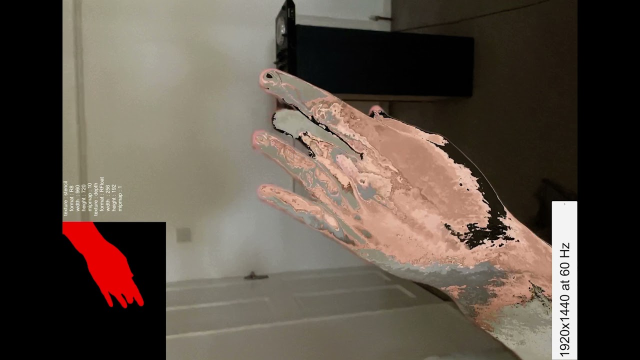
So I'm trying to get this to cover my hand both portrait and landscape
Currently, it only works in portrait mode
how do i choose a texture instead of colour in my shader? right now its just a color but i would like it to be a texture

Sure. Just provide a texture to the shader and sample it instead of just outputting color.
here is my shader
normally it should just work
but it doesnt work
it doesnt show up my lightmap
also I have a question
Is there a way to render the texture used in the material in this URP render feature into UI Raw Image component? https://github.com/Unity-Technologies/Graphics/blob/master/com.unity.render-pipelines.universal/Samples~/URPPackageSamples/RendererFeatures/KeepFrame/KeepFrameFeature.cs

GitHub
Unity Graphics - Including Scriptable Render Pipeline - Graphics/KeepFrameFeature.cs at master · Unity-Technologies/Graphics
I've just updated an older project at work, from 2019.4.21 to 2020.3.20. It's using URP, and there's a custom shader giving me errors. This was written by someone no longer at the copmany, and I don't know shaders.
Shader error in 'Custom/Tile01Test': Invalid conditional expression. at /Immotion/1093_OceanCube_AR/1093_OceanCube_AR/Library/PackageCache/com.unity.render-pipelines.universal@10.6.0/Editor/ShaderGraph/Includes/Varyings.hlsl(101)
This looks like an error in Unity's .hlsl?
hlslcc class
no
hlsl is a machine shader code
it might be that this file is either outdated or written wrong
Hey all. Anyone know if we can set Stencil properties in Shader Graph as of 2021.2?
Hi, Does Unity Shader Graph has a corresponding node for clip() method (the one that discards pixels)?
hi
I need some help
I made a simple shader and I created a new Gradient Property, but when I save the shader and create a new material, the gradient property disappears any idea how to fix this?

oh wait I just noticed that gradients are not exposable
😐 why?
i really need this
nvm Fixed
I have these while lines that scroll down.
When they reach the end, they should be transparent but its not working.
Does anyone know how to fix this?

            fixed4 frag(v2f i) : SV_Target
            {

                fixed2 uvs = fixed2(i.uv.x, (i.uv.y + (_Time.y * -_Speed)) * _TextureScale);

                fixed4 col = tex2D(_MainTex, uvs);
                // apply fog
                UNITY_APPLY_FOG(i.fogCoord, col);
                return fixed4(col.rgb * _Color.rgb, col.a * (1 - i.uv.y) * _Intensity);
}```make sure to have "Queue"="Transparent" and "RenderType"="Transparent" (neither of those is required (iirc) to make transparent tho, only recommended I guess) tags on the shader. You also need to use Blend command to make transparency work.
Its also rendering infront of everything, Do you know what causes that

these are the settings for the lines that arnt getting less transparent as it gets further back

well, that's caused by transparent object sorting issue, that happens because transparent objects doesn't use zbuffer testing. I'm not sure what would be best solution in your case...
I feel like i've just wasted 4 hours
Is anyone using projectors on 2021.2 on Android? Something is seriously broken, Unity is binding random textures to the shader rather than what's supplied.
Under the Graph Settings you can enable Alpha Clipping, and then use the Alpha and Alpha Clip Threshold ports on the master node/stack. (If alpha is below the threshold the pixel is clipped/discarded). You can probably also use a Custom Function node with the usual code methods (clip() or discard;)
You are using uv for the alpha, so could you show us the model uv mapping?
I cannot show that unfortunately, i got my collegue to model it for me, I have zero modelling knowledge
Question. I keep seeing the word "buffer" in regards to shaders such as "frame buffer", "depth buffer", "compute buffer". What does it mean in this context?
basically an array of some data.
Thank you Cyan ❤️
I'm running into an odd issue with DrawMeshInstancedIndirect
I have here a single quad which I'm feeding into that function and then passing in a big buffer of positions that are randomized
in my shader, I am applying this billboarding logic:
            v2f vert(appdata_t v, uint instanceID: SV_InstanceID) {
                v2f o;

                float4 pos = mul(_Properties[instanceID].mat, v.vertex);
                o.color = _Properties[instanceID].color;

                float4 world_origin = mul(unity_ObjectToWorld, float4(0, 0, 0, 1));
                float4 view_origin = float4(UnityObjectToViewPos(float3(0, 0, 0)), 1);

                float4 world_pos = mul(unity_ObjectToWorld, pos);
                float4 view_pos = world_pos - world_origin + view_origin;
                float4 clip_pos = mul(UNITY_MATRIX_P, view_pos);

                o.vertex = clip_pos;

                return o;
            }
but the collection of quads rotates like it's a single mesh with a weird pivot point
Am I misunderstanding how this works here?

Gist
Simple Billboard shader for Unity. GitHub Gist: instantly share code, notes, and snippets.
color math in shader is "just" color values for RGBA.
So add is add. Plus. Sum.
.5 (grey) plus .5 (grey) = 1.0 (white). Double the grey.
Blending, requires that you mathematically MIX the colors, that's what nature is (kind of) doing. In nature, it's really reflective (subtracting) colors as white light hits the material, some frequencies are absorbed and others reflected.
But with RGB output, we basically specify how much is reflected only...how much red, green or blow is sort of EMITTED/reflected. (Not to be confused with actual light from a "bulb" in lighting calcs).
So if you have a blue light reflecting, and your shader tells it to add red light in, you get purple.
Mixing comes in several ways.
Usually it's multiplication....since intensity is represented by the magnitude of the values.
If you have a single only-green light source in your scene, everything will look like some kind of green, that's the only frequency of light available. Red things would look black since there's no green reflecting from them.
It's easy in a shader....you'd just multiply your pixel's albedo value by your light color (myColor * LightColor). And you'd get only the green amount as a result since R and B would be 0.
Alpha blending is another topic and too long for this post but:
https://docs.unity3d.com/Manual/SL-Blend.html
So I have this shader in a material that is applied to both a grass object and the plane object underneath it to give a sway effect

However if I try to apply the same material that has the shader to another plane object in another scene, I get this all black look and the sway goes crazy (like, leave the entire mesh and stuff)

Any idea what might be causing this?
Long story short, it's related your object's UV...
most grass sway shader would take UV-0 as the bottom most of the object.. while for plane object as you mentioned above,, well...
Move the object origin in the mesh to the bottom.
Use the world-space Y offsets as a height calc for the object. You could do object-space too if you wish, depends on what you're doing externally.
IDK why you're "moving" the plane object, if it is really a plane.
I think this is much of what @patent plinthis saying? But it's not UV related, it's vertex/world space (or object space) related.
The thing is if you use world-space, you get the results of the object rotation and scaling (which you'd do first).
I mean, moving the object origin to the bottom while the object itself is just a plane, doesn't make sense still 😃
Hey everyone... I've created a simple shader for my models using Lit/Metallic/Opaque however there's this "metallic" reflection. I tried setting the graph to specular but then the models became "darker"... Is there any other way of working around this issue?
I'm trying to figure out if there's a way to add fresnel functionality to the HDRP lit shader without having to completely recreate it... any ideas?
Yeah, I have no idea why they're "swaying" a plane, when they have separate grass meshes, either.
I'm not really the artist who made the shader, but they said it's supposed to be on both the plane object and grass because it has a paint effect
Or something
I'm just trying to maintain the artistic vision intact
I have the same issue using this code
Managed to solve the above issue.
Now running into transparency problems

It looks transparent and shows the terrain below
but it's blocking other transparent meshes
using Blend SrcAlpha OneMinusSrcAlpha and Tags { "RenderType" = "Transparent" "Queue" = "Transparent+500" } should do the trick but doesn't seem to work for me
You can see the square outline of the mesh
Did you also do ZWrite Off?
So, I'm not exactly used to unity shaders, but if your texture only uses transparency on the background, you can discard pixels that have a transparency of less than a threshold (i.e. < 0.9), that way they won't cull textures behind them
@low lichen omg that was it thank you!
Is there a way to stop my material on this TMP being (instance) ? It breaks and doesn't render but when I switch it back to the non instanced material it renders fine. Very frustrating.


My sprite doesn't seem to be lit up properly after a certain range
You can see this darker coloring in front - as I move the camera the sprites get lit up differently
You can see after this threshold the outlines of the sprites become white rather than the darker green they are in the first rows
https://puu.sh/IoZvT/d41f80c64c.gif
How can I go about creating this overlay effect in a way thats performant?
This example is just behind the character, but I want this to be visible through pretty much everything, as we want to be able to see other player's hearts.

It sounds like a second camera and layer is an easy solution, what would yall recommend?
We are using built in pipeline for light limit reasons
idk. kinda like put them in a diff scene or smth, or increase their priority or smth?. similar to what they do with guns in FPS games?.
Yeah, like preventing your gun from poking into the wall but still having lighting and all that?
light eh?. idk.
I tried changing render queue but nothing seemed to happen
I was able to use a simple health bar in place with UI overlay shader, so would that not exist for simple 3d meshes?
We could use the same shader but it doesnt allow texture, turns it all flat
I thought, given your name, you might know a guy 😆
but yeah. your game looks great man.
lol. I just got here
Thanks, i dont know the rules about advertising but if you dm me i can share title/page
Question. If I wanted to add some kind of temporary graphical effect to a mesh, would I need to modify the material of that mesh first? Or is there a work around?
What I mean by "graphical effect" is something like the star power up effect in Super Mario games where the entire mesh glows in various colors.
Make another material and swap it while the effect is active 👍
Hey guys any clue why my tessellation shader might have the correct vertices but fragments as if it were a triangle mesh. (tessellated quad mesh on the left, tessellated triangle mesh on the right)

maybe try using a shader with
ztest always
After some searching it looks like I could modify standard using that, thanks
guys i made a custom forward renderer so i could render some objects on top of eachother
but now the objects in the same layer won't view correctly and go top of eachother when they're behind one another


the parts of the hands that're supposed to be behind the weapon are rendered in front
this is how its supposed to look

If you're rendering the gun with a separate camera make sure it's depth is smaller (or was it bigger?) Than the main camera.
I was trying to eliminate the second camera but as it seems its the best way for fps games
The render pipeline is too experimental to be used for now
ztest always...It's a start. It will write, but could be overwritten.
So you'll (probably) want to control the draw order too. So queues, or like you said even another camera layer. Unless there's no depth to the hearts (E.G. they're basically close to the near plane of the camera, and you write z depth, so nothing overwrites them). Can't tell if you're in 2D or not.
Hi i've some troubles making a compute shader. The error come from the for statement when i try to edit a RWStructuredBuffer<float3> (tris l.360) the compiler don't accept it and I really don't understand why, if someone have an idee .. (error code from compiler : Compiling CSMain: Internal error communicating with the shader compiler process. Please report a bug including this shader and the editor log.) Thx !
Not 100% sure, but it could be because you're trying to write to several places in the buffer. I'm doing marching cubes too and I write triangles to a Triangle structure buffer with 3 float3's.
"write in several places in the buffer" ? i'm not sure to understand why is it a problem
I have also tried with other containers and the same error occurs
Because other threads could be overwriting values.
Just as an experiment, try writing 1 value only.
like this ? I get the same error. But even if they are some wrong index overwriting it still should be compiled no ?

Not like this. Use some unique ID instead of 0. It could be that the compiler prevents such a shader from being compiled. That's still just a guess but it's worth testing it properly.
If I remember correctly, I use .Append in my shader
Aah, right, I'm using append buffer
Output buffer that appears as a stream the shader may append to. Only structured buffers can take T types that are structures.
Did you write the shader yourself?
Yep
Mine is based on Sebastian League tutorial on marching shaders.
And he used append buffer for the triangles.
If you look at the examples on unity docs, they always seem to use the thread ID if they want to write to a regular structured buffer
https://docs.unity3d.com/2018.3/Documentation/Manual/class-ComputeShader.html


Yeah, that should be it.
the line tris.Append still create same error
Weird
Yes that's the word
Wait what's Triangle
Aah
Lol, didn't notice it first
Should work if you ask me.🤔
Is that the whole/only error?
I've also tried with other containers like RWTexture1D and i get the same error
It's the only error yes
Not other errors or warnings occurs
Not very useful.🤔
Yep ><
Is there anyway to get an objects local position in shadergraph?
I think position node has that option.
Wait, you mean local as in relative to the parent?
why is the main preview always empty when I start a new Lit Shader Graph?

Do the shader work at all (in inspector for example)?
hiya where would i start in making a portal shader
How difficult is it to create a shader that has animations baked into textures and then plays them in a geometry shader?
I think it's called GPU skinning
The DOTS battle/strategy demo rendered thousands of animated characters that way
Although it has nothing to do with DOTS...
i have a simple psx shader i found off of github and i've been trying to properly add emission to it for a few days now

the result i have now is pretty damn alright, the problem being that if i disable the emission texture it keeps the actually map tied to the albedo
(the "face" part is supposed to be completely black)

thats because i have this at the end of my method, but i dont know how else i'd overlay the emission map
does anyone have any advice?
Yes, the object node old only has the world position
(no longer require this specific solution)
Guys, I'm aiming to make a character sprite that has back and front only, for a 3d game, should I do a billboard sprite shader that changes the sprites depending on the camera angle, or a c# script would be better than a shader for that?
All suggestions are welcome and appreciated.
A very good example of what I'm aiming to create is how the main character on "Here Comes Niko!" looks.
Does anyone know why this happens? The water defaults to a y tranform of 0 at certain angles, its made with shader graph.

Share the graph

doing it via script might save you from headache at the long run
performance-wise, via script isn't it heavier?
It depends, do the billboards only applies at the player, or other npcs/enemies, or the whole objects are billboarded?
But even then, if it's me, I think I'll go by script first until the performance starts to get a hit
only characters, the scenery is all 3d, so I'll go with scripts :P thank you so much!
I've been trying to implement portals in HDRP for quite a while now, and there's always something that blocks out whatever I try to do. Currently we have Multiple cameras + Render texture portals, where each camera outputs to a render tex, which is used on the portal view quad. This however, is very hazardous to performance with roughly ~4 portals. (Even after adding multiple layers of optimisaition, like disabling the portal when not in view, reducing tex quality when very far away etc). On a potato system you say hello to <5fps. On a decent one, it drops down to 60-70 fps from 200+
On further research, I've come across this which uses a single camera and no render textures, https://zims-en.kiwix.campusafrica.gos.orange.com/wikibooks_en_all_maxi/A/Cg_Programming/Unity/Portals which I assume is basically a transformation shader.
My first question : Does this implementation require duplicate geometery? The example/explanation given in the blog is for 2 different scenes, whereas my usecase requires the portals for a single scene. Second question : If it does require duplicate geometry, would I have to duplicate the scene for each new portal I want? Is this an arguably "ok" way of doing portals? I'm fine with them not being recursive.
Are there any other helpful links/techniques anyone has to do performant portals?
How can I get the animated color/gradient from my built-in particle system to my shader graph ??
I've tried _BaseColor, _Color, ... the color does not seem to pass through
That color is stored in the vertex color of each particle iirc
so how do I read it from my shader ?
With the vertex color node
@mental bone Thanks 👍 that did the trick
Np
Anybody has any experience regarding sharp blended terrain shader?
@patent plinth keywords to use for this are "terrain height blending" or "terrain heightmap blending"
you can find tons of resources on the topic if you need, or find terrain shaders that implement it
Thanks! I tried that, already, but it comes out pixelated between seams/textures... I'm still tinkering with it!
not just tiny pixels, but like gigantic squares for no reason...
Is there an alternative to OnRenderImage() for URP?
I was trying to create a shader effect where the material would be two but getting this weird effect. Any idea why ? I turned off all the lights in the scene but still getting this weird effect

This is my shader

Anyone know how to create an effect like this? Just the brain specifically (transparent with what I assume to be a fresnel effect?) https://www.instagram.com/reel/CWPjluVlbWD/?utm_medium=copy_link
The thing I'm unsure of how to do is the transparency.
It's transparent, but not rendering any of the internal or back geometry I guess?
I've been trying to re-create this reaction diffusion effect in shader code - I don't suppose anybody has any experience doing anything like this? I don't have any experience with this type of conversion https://youtu.be/h2khW5s2AJw

Hi guys,
I started playing around with this really cool algorithm that produces very strange organic results using a relatively straightforward algorithm (with some help from the internet!).
Check it out to see what weird results you can achieve :-)
A much deeper insight on "how" the algorithm works can be found here: http://www.karlsims.com/...


I have this chroma key shader that that a discard based on color + range. It does not cull.
Front faces work great, but back faces are leaving a ghost trail around. Anyone have an idea of what I'm missing in the shader to make it behave ( not shader graph, but surface shader 🙂 )
If you're in SG v10+ double click on an existing connection (or right-click one, should be an option to create a Redirect)
I see. thanks
@zealous plank keijiro also has custom render texture example for that effect: https://github.com/keijiro/RDSystem

GitHub
Reaction-diffusion system with CustomRenderTexture. - GitHub - keijiro/RDSystem: Reaction-diffusion system with CustomRenderTexture.
(not sure if it was mentioned on that video)
whats a good place to learn about shading?
Is it possible to apply a shader effect to URP terrain? From what I've gathered the URP Terrain Lit shader is drastically different from a URP Lit shader, and most tutorials out there apply a custom "terrain" shader to a mesh.
there's no "Terrain ShaderGraph" atm... apparently there was some person working on it but this comment doesn't really give confidence this will be finished any time soon: Opening this draft PR early to get eyes on it from ShaderGraph and ShaderSandbox before I leave. Will also be commenting the changeset to make the transition easier for the new code owner.
https://github.com/Unity-Technologies/Graphics/pull/6056
basically, the guy working on that functionality just left Unity so wouldn't expect anything to happen on the terrain SG in short term
@calm aspen
Oh. But is it how it should be done? I mean terrain shader has additional passes, so maybe any effect should be added on top of the terrain shader?
if URP decals work on top of terrain, I guess you could use them there
there are also tons of third party terrain shaders, even for URP
also are you sure the stock URP terrain setup isn't good enough for your uses?
bit hard to recommend anything without knowing what you are missing
To be specific, I elevation need contour lines and I was unable to find anything. Alas I cobbled together a shader, but it works only for meshes.
But then I picked up Map Magic for a procedural terrain solution, and it requires a terrain shader. 🥲
you sure your URP shader doesn't work on terrain? I've never tried that on URP, on HDRP people used just HDRP layered lit shader for terrain before Unity actually implemented terrain shader for HDRP 🙂
I'm not sure how it suppose to work. According to Map Magic documentation, I need to apply material in the generator itself. And only one based on terrain shader works. However, I do have access to the generated Terrain object, yet it doesn't have Mesh renderer to apply material on.
you apply custom terrain material into terrain's settings
there's a slot for it
(the small tab with cogwheel or something)
been ages since I've used unity terrains but should be something like that
but if Map Magic hardcodes that to specific terrain shaders then that's another thing (you can still overwrite the setting if you want)
I guess it relies on splat textures and other inputs from the terrain shader.
MM store page suggests it has nodes to provide compatibility with 3rd party terrain shading too
but yeah, you may want to ask about this on their forum thread
Yay! I found it, and it gives readable error about tangent gemotery.
It seems I need to rewrite tangents calculation and then replace albedo with my shader in hope that it will act as a texture.
sorry for noob question, but i want to pass custom UV data to shader, because i'm using sprite atlases. I know that this is a common thing but i can't figure out how to pass sprite data to shader. I have 1x16 texture placed somewhere inside atlas, and Sprite.UV gives me 4 times (0.2, 0.4) and i can't understand why all 4 values is the same, while they should be like ratio rect for texture
hey all so i have been stuck on this issue for like 3 days and i can't seem to figure it out. our project makes heavy use of assemblies and for some reason we cannot seem to find the unity shader core code although we have added the dll any ideas>

I have strange issue. I use really simple shader and in shader inspector i have nice SRP Batcher: compatible label, but when i inspect Frame Debug all my sprites, which uses same textures (2 in shader), produces single drawcall. And Frame Debugger tells me that SRP: Node is not compatible with SRP Batcher on 1st sprite and Objects have different MaterialPropertyBlock set. on all next sprites drawcalls. Any idea what is going on?

And this issue goes with any kind of material wtf
The shader might be compatible, but afaik sprites are not compatible with the SRP batcher, only regular (or skinned) meshes. I think they render with dynamic batching instead (hence most sprites are still combined into one drawcall).
If you use any Material Property Blocks on the renderer component that also breaks compatibility too.
Does anyone know if there are any publicly available scripts to downgrade materials from HDRP or URP to the standard pipeline? I accidentally bought an asset which I'd like to use with the standard pipeline which only has materials authored for those two, and I'm not sure what the differences are, having not used those pipelines, though it seems like HDRP supports things like bent normals and has some kinda metallic mask, so I'm not sure how much work I'm gonna have to do in photoshop to make these compatible with the standard shaders.
So, do you thing guys is possible to create this effect in Unity?
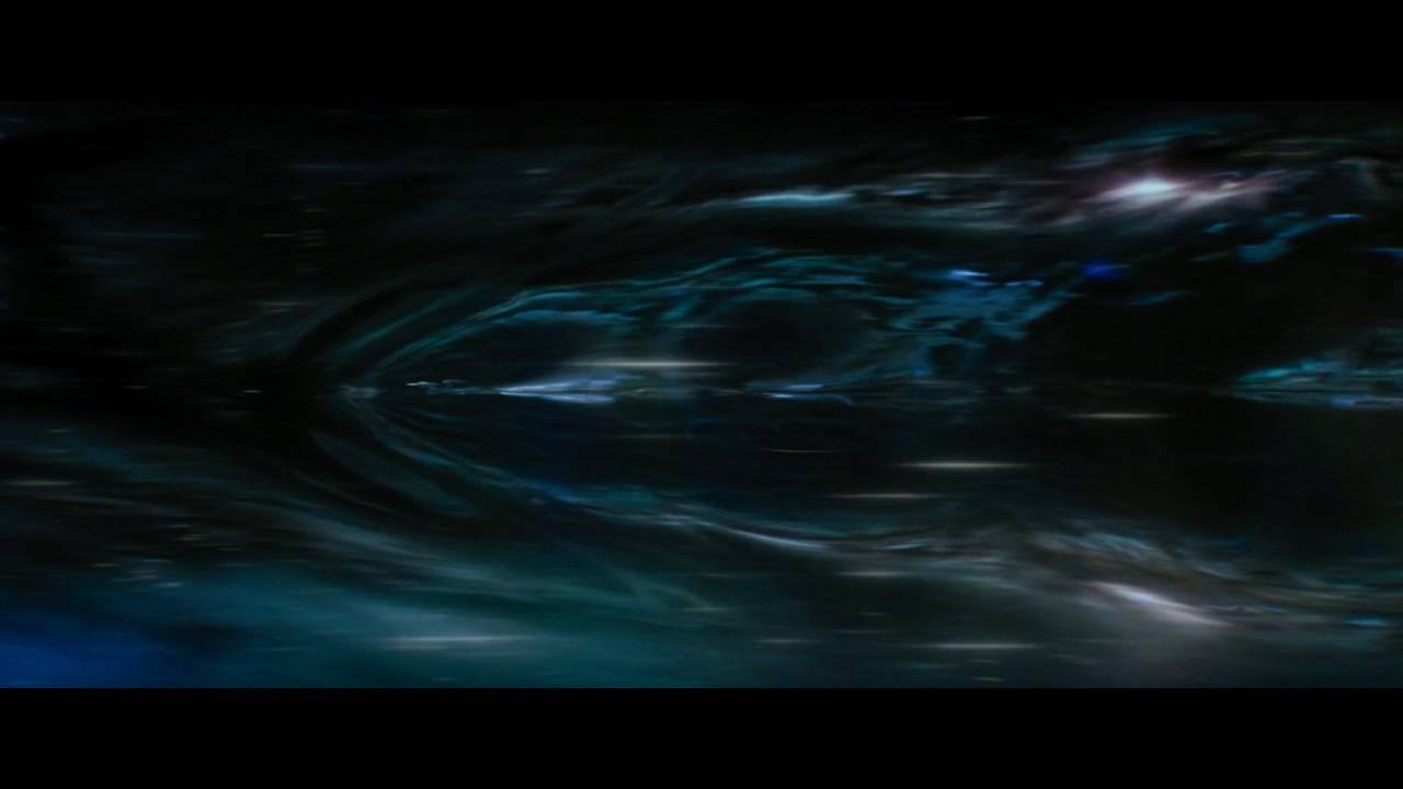
Short but awesome; the brand-spanking-new warp FX from Star Trek Beyond. The first time we've ever seen the warp bubble and the bending and warping of spacetime as the Enterprise travels faster than light.
Gorgeous new effects, I hope the next film has more shots!
So there is no way to send data to sprite shader and not break srp batcher at the same time?
Probably easier to convert the URP material. It mostly uses the same maps as BIRP.
anyone know the best way to draw a line with constant thickness ?

how to make a hdrp ui shader using shader graph for overlay canvas?
how do you handle assembly references with shaders
What do you mean?
@low lichen i am currently making use of amplify shaders but i cna't seem to save anything as it says amplifystochasticnode is null. and without that it says i am having these cache errors. and i believe its caused by my asesembly references. i created a new branch and removed all assembly references and it worked. but then we can't have tests

Someone just took over 😃
My guess it will be in 2022... hopefully it will be in 2021 as well

@patent plinth there's 0% change it will go into 2021, Unity doesn't backport features. Even 2022 is super hopeful considering they changed the person working with this. Typically they require like one year of dev time to get anything near to state they want to merge... and considering the Terrain SG work is still very WIP and new person is likely to redo a lot of the past stuff, I wouldn't really count on seeing this on 2022 cycle either
I mean with some luck it might happen but seeing how these things go, I would assume it's not happening next year at all
Kinda confusing why they've never seen the importance of doing this since the very beginning of SG.. well, at least we almost got it now... not quite, perhaps


thank you so much!!!
I noticed I didn't actually push the HDRP fork of that to my github
ported that effect a long time to HDRP just for CRT testing
Not what I've expected, but at least that's something! 👀

you want actual hard lines?
Yes, I want lines and a vertical gradient. As of now, the entire shader effect is squashed between each "line", so the actual lines from my shader are not visible here.
like one vertical gradient total or gradient for each step?
Preferably the overall UV gradient, although I have to admit these stains per line looks nice.
for the lines, I suppose you could just put smoothstep there to get rid of the current gradient but have some smoothing to it and then multiply that with the final gradient
I'm by no means good with shaders though so I hope others can chime in
guys, is there any workaround to using custom data in URP shader with sprites and not break SRP batcher? Can't believe it goes by design!
It seems from our previous discussion you know about shader way more than I do. 😅
Been scratching my head for hours because my compute shader didnt work
until i noticed this

how to make raymarching in shader graph?
You'll find the solution Here : https://iquilezles.org/www/articles/distance/distance.htm
Enjoy !
Articles on computer graphics, math and art
I totally forgot about Iq blog -_-"
@daring dew Thanks for the reminder
You can do raymarching in shadergraph using a Custom Function Node.
But make sure to add the attribute [loop], above your "for" or "while" loops or shadergraph might display an error !
I don't know how to write basic shaders on hlsl. Can you send me a tutorial please?
Do you have a visual example of what you are trying to achieve !?
Yes, it is totally doable !
If you are using the URP and shadergraph, there is a Sprite Shader template, that should work with sprite atlases. I have used it, and it works !
do you mean this?

something like this

i wanna add something cool to this

this cubes moving backward and forward
Yes indeed !
My shader was created from template from the start, the problem no is when i pass custom values inside sprite shaders it breakes SRP batching
i have read some posts on forum describing that sprite renderer construct combined meshes for same sprites every frame for performance purposes, which can't be done if i have different material property block
Where can i see list of unity default properties name like _MainTex ?
this depends on the renderer you use
for built-in renderer you can find the shader files on Unity site, before they have been precompiled
each Unity release has built-in shaders as additional download on their site
for SRPs, you can look for Lit.shader file on URP and HDRP to see the properties they have
any ideas how to add normal map to unlit graph ?
My attempt to make a visible kind of wind via shadergraph... basically this is just a volumetric fog but dayum this thing is expensive
but why? there's no light to reflect from it
as olento said, setting normal map into master stack doesn't make sense since unlit shader doesn't calculate any lighting automatically. If you want to implement your custom lighting or smth like that, you can use Normal Unpack node to unpack the sampled normal map texture and then use Transform node to convert the tangent space normal into world space for example. Now you can use the output to calculate lighting etc. using world space normals that's affected by normal map texture.
Can anybody help me why this does not work correctly? Trying to get the screen position of the objects center (0-1)

hey guys, I made a shader for lit sprites in 3D (perpendicular to 3D geometry). I also added an emission map for that HDR glow goodness. Is it possible to make the emissive areas behave as unlit pixels? Right now, if the sprite is put into a deep shadow it darkens down the emissive area and it stops glowing
iny idea how?
Maybe try this.
https://forum.unity.com/threads/is-there-a-way-to-get-an-objects-screen-position-in-the-shader-graph.713885/#post-7159663
Unity Forum
That's the position of the object itself, not any particular vertex or fragment. It seems like it should be easy, but unity doesn't seem to be making...
Yeah thx I also found this. I tried to recreate it but it didnt work as intended. But I figured it out eventually. I was missing the perspective devision part
how do i render an object later / last but still behind other objects?
No one is gonna be able to answer you just from looking at the inspector part of it...😅
yea sorry im really new to this and im struggiling like all hell
but ive moved on from that
so ill just delete it
before or after light calculation ?
well, as I said, you can use the normal you get from Transform for lighting calculations
got it , thanks
atleast I hope it works that way, i'm not very familiar with normal stuffs and I may have forgot something
Hey all, a bit of a beginner when it comes to shader(graphs) and i'm trying to make a "team color" shader that also "respects" the texture underneath. The masking part was doable however I'm having trouble combining the greyscale texture with the desired color without the texture looking faded or overpowered by the color.


on the top (the original texture) you can see that the plane has "grooves" but the mask overpowers that.
Now if I change the mask to be more "grey" I'd get more of the texture, but less of the color

I'm looking for a way to create a combination of these red planes
using a Lambert method for light, do i multiply the world space transformed normal map with the mesh world normal vector , and feed in the result in this method , or would it be rather be additive operation instead of multiplication ?

I think what you want is to multiply the team colour with the other texture, instead of the mask texture
hey cyan 👋
Wouldn't that also change the color of the non masked areas?
By transforming the normal map (tangent) to world space it already includes the normal relative to the mesh. It's not additive/multiplication, just replace the normal direction entirely.
Yeah, but should just need a Sample Texture 2D (Normal mode) -> Transform (Tangent to World, Direction), then send it into the Lambert function.
Normal Unpack is only needed if you use the Default mode on the sample instead. The Normal mode already does it for you.
got it
No, because the Lerp is already using the mask. I was referring to replacing the Multiply B port only.
u can use the b&w texture as it is without inverting the colors - just replace the A & B nodes in the lerp
thanks!
also i would use a global scale value that multiplies the TeamColor value or a lerp to greyscale of the same node -
instead of modifying every single mask texture / colored texture to be more or less grayscale
something like this
( ^ two methods to get greyscale color )

Anyone have a link to a good course in HLSL for Unity?
An updated version of this article can be found here : Intro A lot of shader code tutorials you’ll see online are written for Unity’s built-in pipeline and won’t really work in the Universal …

I've been having issues importing sketch up files into Unity, previously I was able to "extract materials" for unity to be able to render the model in the scene, but I can't seem to do that anymore. I think sketch up might have updated where the materials are stored in the file. Unfortunately, I did not create these files so I can't remake them in an old version of sketch up.
Does anyone have any idea how I could import these files? I think this is the most relevant channel for this question
For reference, this is what I am seeing now

Right now I'm trying to convert the sketch-up file to something Unity might handle better, like .obj. We'll see if there's a way I can do it without purchasing Sketch-Up lol. All online conversion tools are just getting errors
you can get a free trial for SketchUp (Pro) no problem!
That seems to have worked! I just exported it as sketch up 2019. Now the only issue is if I need to convert more files after a month haha
Here's the model, if you're curious

I've created a halftone shader in shadergraph in URP that I'm quite proud of. However when the camera pulls away the result looks quite messy. Is there any way I can convert this to more of a screenspace effect? Or do I have to make this a post-processing effect?

@regal stag Hello again! (I hope i'm allowed to @ people, if not i'm terribly sorry), I'm using the lighting scripts you gave me before and i'm trying to figure out how to implement additional lighting- I may be out of my depth quite a bit here, but I've read the descriptions of how the additional lights and shadows scripts are handled and i'm pretty lost XD. Is there a way to create a node that will output the additional light shadows without using keywords? if this isn't possible or i'm being dumb i'm sorry!
(I dont mind the @, I'll probably see it either way but it's usually best to keep new questions open to everyone as there's likely others that can answer too)
The subgraphs I wrote (https://github.com/Cyanilux/URP_ShaderGraphCustomLighting) has an AdditionalLights example (and toon version), should just need to Add the result iirc.
The keywords in comments are also required. Without them Shader Graph won't do any shadow calculations.

GitHub
Some custom lighting functions/sub-graphs for Shader Graph, Universal Render Pipeline - GitHub - Cyanilux/URP_ShaderGraphCustomLighting: Some custom lighting functions/sub-graphs for Shader Graph, ...
got it! I'll give it a shot- thank you again!
Hello again! super weird error- whenever i add the _ADDITIONAL_LIGHT_SHADOWS keyword into a material's keywords in the debug mode, objects with that material assigned black out at random camera angles, even when i haven't added anything into the shadergraph itself
A little more debugging later, it only turns certain obects black when they are within the radius of an additional point light. Also interesting is that objects within this range seem to flicker between pitch black and the appropriate color depending on camera angle?
So I have a transparent object here with a fresnel effect. The probably I have right now is that I am able to see ALL front faces of the model.
I'd like to only see the first front face from the camera out.
@regal stag I went ahead and did even more testing and it seems whenever i add the _ADDITIONAL_LIGHT_SHADOWS to any material, it produces huge fields of black areas, which is alarming because that's what was happening when i used keywords to enable the main light shadows before i found your awesome lighting assets the first time! Any insight to this very weird problem would be appreciated!
Something like the `Transparent shader with depth write' here?
https://docs.unity3d.com/2020.1/Documentation/Manual/SL-CullAndDepth.html
I ended up figuring it out with 2 materials. One to write to the ZBuffer, and the other to just apply a fresnel effect.
The problem now is figuring out how to apply it to multiple objects.
I dont want to see that middle portion, since the mesh on the right should be covering it
Hey everyone. I followed Ned Makes Games's wonderful tutorial on how to make a custom hlsl lighting node (this one here: https://nedmakesgames.medium.com/creating-custom-lighting-in-unitys-shader-graph-with-universal-render-pipeline-5ad442c27276), but it only does diffuse and specular lighting calculations. Does anyone know what I would do to convert it to take metallicity as a parameter for the light equation along with diffuse color and smoothness?
I'm basically looking for this, but with metallicity as a parameter as well:

Idk bout shaders, but backface culling?
I don't think so. transparent sorting problem and backface culling are different things.
then how about using opaque shader instead of transparent?
if you're supposed to see through the brain, opaque won't be solution either
If you start using screenspace uvs, your pixels will probably shiver. I would suggest checking the distance of the transform to the camera in the shader and switching between 2-3 hatching scales.
Hi all I am trying to create a shader that forces rendering on top but I also need alpha from the texture to be used (along with blend mode ideally) any ideas what I can change please
{
    Properties{
       _Color("Main Color", Color) = (1, 1, 1, 1)
       _MainTex("Base (RGB)", 2D) = "white"
    }
    SubShader{
        Tags
        {
            "Queue" = "Overlay+1"
            "IgnoreProjector" = "True"
            "RenderType" = "Transparent"
        }

        ZTest Always

        Blend SrcAlpha OneMinusSrcAlpha
        ColorMask RGB

        Pass {
            SetTexture[_MainTex] {
                constantColor[_Color]
                Combine texture * constant
            }
        }
    }
}```the render on top works great
Hi, I am following this article, trying to make some fog of war effect and I need to plug a render texture into a shader to be used as a mask. Is there a way to do it in shader graph ? If so is there a tutorial I can follow, currently looking but not having any luck.
Also the last bit I don't know where to go, is how to render that shader. As I am using URP, I am thinking maybe making a render feature for the special camera ?
https://crussel.net/2016/06/09/unity-visibilityfog-of-war-effect/

Here’s a method for ‘fog of war’ from an old Unity project. This is the kind used in games like XCOM where the world geometry outside the visible range of your units is darkened, …
My very first shader graph results, aoe decal with fill color and multistroke border
The circle on the top is the object with the shader material and I render that to a rendertexture which I then use in the decal shader. seems kind of inefficient.
Also the shader itself seems kind of inefficient, I'm using a few comparison/branch nodes. Tried it with step but couldnt figure that out.
Hello people, I am attempting to edit sampler2D _MainTex tiling and offset inside of a surf function of a shader, but I can't seem to get it right and I can't seem to find a solution online. Does anybody know if this is possible?
Specifically these values

for more context, I am currently attempting to transform it through ```void surf(Input IN, inout SurfaceOutputStandard o)
{
float2 offset = (0.5, 0.5);
float2 _uv = IN.uv_MainTex * offset.xy + offset.xy;
fixed4 c = tex2D(_MainTex, _uv);
        o.Albedo = c.rgb;
    }```
but this yields unexpected results
the tiling and offset is automatically handled in surface shaders when you us uv_MainTex
oh you mean it further than in the inspector?
the values are inside of _MainTex_ST afaik
Yeah, I meant that I want to modify the values I see in the inspector, I got something to work so far through void surf(Input IN, inout SurfaceOutputStandard o) { float2 uv = IN.uv_MainTex; #ifdef UNITY_PROCEDURAL_INSTANCING_ENABLED float4 scaleOffset = texturePositionBuffer[unity_InstanceID]; uv = uv * scaleOffset.xy + scaleOffset.zw; #endif o.Albedo = tex2D(_MainTex, uv).rgb; }
where texturePositionBuffer[unity_InstanceID]; just gives you a float4 that you pass through compute buffer
Does anyone know a simple way to get a point lights range in HLSL?
HI. I'm very new to shaders and I'm trying to make a very simple shader that will draw mesh based on Matrix4x4 (position) and color (vector4) of buffer.
This is for my modification of game RimWorld (which sadly has no sources for their shaders for me to peek).
And what I don't know is how to get position from Matrix4x4 and turn it into v2f struct.
I make my matrix this way:
                    Vector3 pos = p.ToVector3ShiftedWithAltitude(AltitudeLayer.Gas);
                    Quaternion rotation = Quaternion.AngleAxis((float)(gasGrid.angleGrid[i] + angle + gasGrid.signGrid[i]), Vector3.up);
                    props.mat = Matrix4x4.TRS(pos, rotation, gasGrid.drawSize);
And here is template of my shader. What do I need in ??? part?
            struct appdata_t {
                float4 vertex   : POSITION;
                float4 color    : COLOR;
            };

            struct v2f {
                float4 vertex   : SV_POSITION;
                fixed4 color    : COLOR;
            };

            struct MeshProperties {
                float4x4 mat;
                float4 color;
            };

            StructuredBuffer<MeshProperties> _Properties;

            v2f vert(appdata_t i, uint instanceID: SV_InstanceID) {
                v2f o;

                ???

                return o;
            }
It's supposed to support GPU instancing and transparency (but I guess it's irrelevant for question above)
so you want to get the position of the origin of mesh in world space right?
I guess. I have an array of Matrix4x4 for it
I want it to draw each mesh according to this array
in code above I sent p is IntVec3 which is exact position on map
in trs matrices, the position is saved in the last column
any tip where I can find example with this maybe?
I have very little idea what code I'm supposed to use to get that last column of matrix
and then assign it to v2f
im not very familiar with matrices either but matrixName._m03_m13_m23 should give the position vector (float3) from trs matrix
o.vertex = _Properties[instanceID].mat[3];
I guess like this?
matrix is float4x4
as defined in ```
struct MeshProperties {
float4x4 mat;
float4 color;
};
matrixName[3] gives only one float which is the first element of last column i guess (I'm not able to find how is matrix[index] defined)
hmm, still nothing
                    MeshProperties props = new MeshProperties();

                    Vector3 pos = p.ToVector3ShiftedWithAltitude(AltitudeLayer.Gas);
                    pos.y += gasGrid.layer;
                    pos.x += gasGrid.xGrid[i];
                    pos.z += gasGrid.zGrid[i];

                    Quaternion rotation = Quaternion.AngleAxis((float)(gasGrid.angleGrid[i] + angle + gasGrid.signGrid[i]), Vector3.up);

                    props.mat = Matrix4x4.TRS(pos, rotation, gasGrid.drawSize);
                    props.color = new Color(gasGrid.color.r, gasGrid.color.g, gasGrid.color.b, 255f); //Math.Min(gasGrid.transparencyGrid[i] / 16, 75)
here's how I define my
so what are you exactly trying to do with that matrix?
just to get mesh in correct position and rotation
well, then you need to do vector * matrix multiplication
Basically here, I have about from 0 to 100k meshes I need to draw
I figured DrawMeshInstancedIndirect is the only way I can draw it without going into 5 fps zone
mesh is extremely simple plane with gas texture

is it like particle system?
it's tile based game
I make gas grid
whenever there's red text - means gas is supposed to be drawn

            CGPROGRAM
            #pragma vertex vert
            #pragma fragment frag

            #include "UnityCG.cginc"

            struct appdata_t {
                float4 vertex   : POSITION;
                float4 color    : COLOR;
            };

            struct v2f {
                float4 vertex   : SV_POSITION;
                fixed4 color    : COLOR;
            };

            struct MeshProperties {
                float4x4 mat;
                float4 color;
            };

            StructuredBuffer<MeshProperties> _Properties;

            v2f vert(appdata_t i, uint instanceID: SV_InstanceID) {
                v2f o;

                o.vertex = _Properties[instanceID].mat[3];
                o.color = _Properties[instanceID].color;

                return o;
            }

            fixed4 frag(v2f i) : SV_Target {
                return i.color;
            }

            ENDCG
here shader
first you need to transform the object space position into world space using your trs matrix and then transfer the result into clipping space using UNITY_MATRIX_VP matrix.
I have been following the following tutorial https://crussel.net/2016/06/09/unity-visibilityfog-of-war-effect/, and am stuck on what to do after creating my render texture through code.
I have made my shader through Shader graph, hoping it does the same as in the tutorial, and followed all the other steps. But I don't know how to finish piping the render texture into it, and how to get the shader to work as a mask.
I am in URP render, so I tried going for a base camera instead of overlay, and manually piped the Unitview camera into a render texture -> which was put in my shader-> which in turn was used in a material -> which was put as a render object material override in a forward renderer -> which was used as renderer by all cameras -> which didn't give any valid result
Here’s a method for ‘fog of war’ from an old Unity project. This is the kind used in games like XCOM where the world geometry outside the visible range of your units is darkened, …
sadly it says very little to me, so is google
UNITY_MATRIX_VP Current view * projection matrix.
ig it's just mul(UNITY_MATRIX_VP, mul(yourOwnTrsMatrix, float4(objectSpacePosition, 1.0)))
yourOwnTrsMatrix is float4?
it's 4x4 matrix
oh, so it's float4x4
yup
o.vertex = mul(UNITY_MATRIX_VP, mul(_Properties[instanceID].mat, float4(objectSpacePosition, 1.0)));
so I guess
is that it?
you need to replace objectSpacePosition by the object space position of vertex (i.vertex in this case ig)
if it doesn't work, i'm out of the game
let's hope for the best, testing...
sadge
            CGPROGRAM
            #pragma vertex vert
            #pragma fragment frag

            #include "UnityCG.cginc"

            struct appdata_t {
                float4 vertex   : POSITION;
                float4 color    : COLOR;
            };

            struct v2f {
                float4 vertex   : SV_POSITION;
                fixed4 color    : COLOR;
            };

            struct MeshProperties {
                float4x4 mat;
                float4 color;
            };

            StructuredBuffer<MeshProperties> _Properties;

            v2f vert(appdata_t i, uint instanceID: SV_InstanceID) {
                v2f o;

                o.vertex = mul(UNITY_MATRIX_VP, mul(_Properties[instanceID].mat, float4(i.vertex, 1.0)));
                o.color = _Properties[instanceID].color;

                return o;
            }

            fixed4 frag(v2f i) : SV_Target {
                return i.color;
            }

            ENDCG
oh, I actually didn't notice
there's some kind of error
incorrect number of arguments to numeric-type constructor Compiling Fragment program Platform defines: UNITY_ENABLE_REFLECTION_BUFFERS UNITY_USE_DITHER_MASK_FOR_ALPHABLENDED_SHADOWS UNITY_PBS_USE_BRDF1 UNITY_SPECCUBE_BOX_PROJECTION UNITY_SPECCUBE_BLENDING UNITY_ENABLE_DETAIL_NORMALMAP SHADER_API_DESKTOP UNITY_COLORSPACE_GAMMA UNITY_LIGHT_PROBE_PROXY_VOLUME UNITY_LIGHTMAP_FULL_HDR
oh wait, float4 should take 4 arguments
do I leave them as 0?
oh, you can just replace the float4(objectSpacePosition, 1.0) by i.vertex because i.vertex is float4 already (and w is 1 automatically)
oh, it also appears that UNITY_MATRIX_VP is float4x4, meanwhile my v2f.vertex is float4
what part of UNITY_MATRIX_VP do I need?
the whole matrix...
but vertex is only float4
and where is the problem?
it doesn't compile
incorrect number of arguments to numeric-type constructor
Compiling Fragment program
Platform defines: UNITY_ENABLE_REFLECTION_BUFFERS UNITY_USE_DITHER_MASK_FOR_ALPHABLENDED_SHADOWS UNITY_PBS_USE_BRDF1 UNITY_SPECCUBE_BOX_PROJECTION UNITY_SPECCUBE_BLENDING UNITY_ENABLE_DETAIL_NORMALMAP SHADER_API_DESKTOP UNITY_COLORSPACE_GAMMA UNITY_LIGHT_PROBE_PROXY_VOLUME UNITY_LIGHTMAP_FULL_HDR
I don't understand what's the problem with multiplying 4x4 matrix by vector...
Possibly I just need smth else to return
and not v2f where vertex is float 4
but I have very little idea anyway
but the one thing is certain is that v2f.vertex is float4, not float4x4
meanwhile result of this multiplying is probably a float4x4
no, float4x4 * float4x4 is float4x4. float4x4 * float4 is float4
oh, looks like it's true
at least, it compiled without errors
let's test
nnnope
I guess in order to test it inside of unity I need to use properties instead of ScructuredBuffer?
assuming no render scripts
Is there a way to find every materials that use a specified shader in my project. I know that there's scripts for this but I was wondering if there was a built in alternative.
Is there a way to access the skinning transformation process in a shader? Ideally as a custom function in the shader graph? I'd like to prebake some object-space per-texel info on a skinned mesh, and then transform it to its later world-space skinned position/normal at runtime.
Or I guess more specifically, I'm looking for a way to transform from unskinned/preskinned object space information to post-skinning object space in a shader (or quickly in a way that I can hand off to a shader every frame).
How to use Hidden/something like this shaders?
I have two shaders
One is normal one
And other one start with hidden/
And hidden/ shader includes some functions of 1st shader
Hidden/ just means the shader doesn't appear in the dropdown menu when selecting a shader on a material. Not sure what you are asking here
Ooo
But I guess those 2 shaders have connection with each other
And their file extensions also different. They are end with.shadervarients
.shadervarients
Extension
I think that means they aren't shaders but ShaderVariantCollections (https://docs.unity3d.com/ScriptReference/ShaderVariantCollection.html). I'm not super familiar with them, but they can record which shader variants the game/scene uses so you can preload them to make sure the required shaders are loaded before they get used.
I'd assume not. That's what shaders are for, not these collections
Parse error: syntax error, unexpected TVAL_ID What is this error?
Shader "Custom/InstancedIndirectColor" {

    SubShader {
        Tags {"Queue"="Transparent" "IgnoreProjector"="True" "RenderType"="Transparent"}
        ZWrite Off
        Blend SrcAlpha OneMinusSrcAlpha

        Pass {
            CGPROGRAM
            #pragma vertex vert
            #pragma fragment frag

            #include "UnityCG.cginc"

            struct appdata_t {
                float4 vertex   : POSITION;
                float4 color    : COLOR;
            };

            struct v2f {
                float4 vertex   : SV_POSITION;
                fixed4 color    : COLOR;
            };

            struct MeshProperties {
                float4x4 mat;
                float4 color;
            };

            StructuredBuffer<MeshProperties> _Properties;

            v2f vert(appdata_t i, uint instanceID: SV_InstanceID) {
                v2f o;
                float4 pos = mul(_Properties[instanceID].mat, i.vertex);
                o.vertex = UnityObjectToClipPos(pos);
                o.color = _Properties[instanceID].color;

                return o;
            }

            fixed4 frag(v2f i) : SV_Target {
                return i.color;
            }

            ENDCG
        }
    }
}
Might be because you have no Properties { } block defined before the SubShader? Not sure if it's a requirement, but I can't see anything else wrong.
nah, I actually removed it after error appeared
bruh
it compiled after restarting unity
😩
How to access texture of material in shader?
if I don't define it as property
it won't be used at all?
What am I doing wrong? Mesh just gets drawn without applying texture at all.
Shader "Custom/InstancedIndirectColor" {
        Properties
    {
        _MainTex ("Texture", 2D) = "white" {}
    }
    SubShader {
        Tags {"Queue"="Transparent" "IgnoreProjector"="True" "RenderType"="Transparent"}
        ZWrite Off
        //Blend SrcAlpha OneMinusSrcAlpha

        Pass {
            CGPROGRAM
            #pragma vertex vert
            #pragma fragment frag

            #include "UnityCG.cginc"

            struct appdata_t {
                float4 vertex   : POSITION;
                float4 color    : COLOR;
                float2 uv : TEXCOORD0;
            };

            struct v2f {
                float2 uv : TEXCOORD0;
                float4 vertex   : SV_POSITION;
                fixed4 color    : COLOR;
            };

            struct MeshProperties {
                float4x4 mat;
                float4 color;
            };

            StructuredBuffer<MeshProperties> _Properties;

            v2f vert(appdata_t i, uint instanceID: SV_InstanceID) {
                v2f o;
                float4 pos = mul(_Properties[instanceID].mat , i.vertex) ;
                o.vertex = UnityObjectToClipPos(pos);
                o.color = _Properties[instanceID].color;
                o.uv = i.uv;

                return o;
            }

            sampler2D _MainTex;

            fixed4 frag(v2f i) : SV_Target {
                fixed4 col = mul(tex2D(_MainTex, i.uv), i.color);

                return col;
            }


            ENDCG
        }
    }
}

Meanwhile my texture is transparent on edges
mul() is for matrix multiplication. You probably just want to use the * operator here (in frag, the one in vert is fine). If you want transparency you need to specify the Blend mode, which you've commented out currently. Also make sure the mesh being drawn actually has UVs.
mesh I use is some plane
oh, switching to * worked
thank you kind sir!
finally

I wrote a shader with Stencil that hides pixels if there is no mask, it works fine, however, the problem is in PostProcessing, namely in Ambient Occlusion, how can this be solved? I would not like to give up this effect.

Maybe your mask shader has ZWrite On when it shouldn't?
@low lichen
No mask shader has ZWrite off
If you're hiding it....just don't draw it?
discard the pixels.
I'm assuming you still draw it, or AO wouldn't be a problem.
What render pipeline is this in?
Builtin
Properties
    {
        _Color ("Color", Color) = (1,1,1,1)
        _MainTex ("Albedo (RGB)", 2D) = "white" {}
        _Glossiness("Smoothness", Range(0,1)) = 0.5
        _Metallic("Metallic", Range(0,1)) = 0.0
        _CutOff("CutOff", Range(0,1)) = 0.0
        _Intensity("Emission Intensity", FLOAT) = 1
        _MaxDistanceRendering("Max Distance Rendering", FLOAT) = 1
        _Distance("Distance", Range(0, 200)) = 1
    }
    SubShader
    {
        Tags { "RenderType" = "TransparentCutout" "Queue" = "AlphaTest" "IgnoreProjector" = "True" }
        LOD 200
        AlphaToMask On
        ZWrite Off

        Stencil
        {
            Ref 0
            Comp Less
        }

        CGPROGRAM
        #pragma surface surf Standard fullforwardshadows

        #pragma target 3.0

        sampler2D _MainTex;

        struct Input
        {
            float2 uv_MainTex;
        };

        half _Glossiness;
        half _Metallic;
        fixed4 _Color;
        float _Intensity;
        float _MaxDistanceRendering;
        float _Distance;
        fixed _CutOff;


        UNITY_INSTANCING_BUFFER_START(Props)
            // put more per-instance properties here
        UNITY_INSTANCING_BUFFER_END(Props)

        void surf (Input IN, inout SurfaceOutputStandard o)
        {
            fixed4 c = tex2D (_MainTex, IN.uv_MainTex) * _Color;

            if (c.a > _CutOff)
                c.a = 1 - (_Distance / _MaxDistanceRendering);

            clip(c.a - _CutOff);


            c.rgb *= c.a < 0.01 ? 0 : c.a;

            o.Albedo = c.rgb * (_Intensity * 1000);
            o.Metallic = _Metallic;
            o.Smoothness = _Glossiness;
            o.Alpha = c.a;
        }
        ENDCG
    }
    FallBack "Diffuse"
Forward or deferred?
Forward
Ref 0, comp less....
I'm just learning
What about the shader that writes to the stencil buffer?
Properties
    {
        _MainTex ("Texture", 2D) = "white" {}
    }
    SubShader
    {
        Tags { "RenderType"="Opaque"  "Queue" = "Geometry-1" }
        LOD 100

        Blend Zero one
        ZWrite Off

        Pass
        {
            Stencil
            {
                Ref 1
                Comp always
                Pass replace
            }

            CGPROGRAM
            #pragma vertex vert
            #pragma fragment frag
            // make fog work
            #pragma multi_compile_fog

            #include "UnityCG.cginc"

            struct appdata
            {
                float4 vertex : POSITION;
                float2 uv : TEXCOORD0;
            };

            struct v2f
            {
                float2 uv : TEXCOORD0;
                UNITY_FOG_COORDS(1)
                float4 vertex : SV_POSITION;
            };

            sampler2D _MainTex;
            float4 _MainTex_ST;

            v2f vert (appdata v)
            {
                v2f o;
                o.vertex = UnityObjectToClipPos(v.vertex);
                o.uv = TRANSFORM_TEX(v.uv, _MainTex);
                UNITY_TRANSFER_FOG(o,o.vertex);
                return o;
            }

            fixed4 frag (v2f i) : SV_Target
            {
                // sample the texture
                fixed4 col = tex2D(_MainTex, i.uv);
                // apply fog
                UNITY_APPLY_FOG(i.fogCoord, col);
                return col;
            }
            ENDCG
        }
    }
writeMask 1 just testing
sry
I think the issue might be related to the shadowcaster/depth pass of the surface shader. I don't think that ends up using the Stencil block, so the depth-prepass doesn't mask anything.
And the mask shader that's writing to the stencil buffer also probably doesn't get drawn in the depth-pre pass because it doesn't have a shadowcaster pass
And since ambient occlusion relies on the depth-prepass for getting the geometry of the scene, it will see it as unmasked

what am i looking at here?
And I'm sorry, it seemed to me that you thought that the Stencil itself didn't work for me either.
I have no idea how to solve it yet because I am not strong in shaders
I'm surprised the ambient occlusion isn't matching the cutout shape (the green stuff?)
Isn't that a separate problem from the masking?
This is most likely a problem due to the fact that the shader is custom, the Stencil itself works well, I just gave as much information as possible
So for now you're okay with the ambient occlusion being a square, but you want that square shape only visible within the mask?
You must be passing ALL the plane's pixels somehow, or it wouldn't be there (wouldn't have been drawn to the depth buffer or whatever).
So that she just disappears
Her being what? The green stuff or the ambient occlusion? Or both?
Except through the mask, right?
Let's forget about Stencil to make it easier to understand each other, I deleted the stencil block how do I remove this frame that AO draws

its standart surface shader with alpha
Discard the pixels except for the green ones.
I will try
But like MS said, watch out for pre-passes.
IDK if using alpha-clipping will work for the pre-passes....might.
Try adding addshadow to the #pragma surface line. That should make it generate a shadow caster pass with the same alpha clipping.
Question: I've implemented this volumetric light effect in a shader and it looks right, but I'm wondering if there's something I can optimize or something I did wrong in translating the math.
https://ijdykeman.github.io/graphics/simple_fog_shader
inline float3 closestPointOnLine(float3 p, float3 lineOrigin, float3 lineDirection)
{
    float t = dot(p - lineOrigin, lineDirection);
    return lineOrigin + t * lineDirection;
}

inline float positionOnLine(float3 p, float3 lineOrigin, float3 lineDirection)
{
    return dot(lineOrigin - p, lineDirection);
}

inline float calculateContribution(float3 lightPos, float3 worldPos, float3 viewDir)
{
    float3 lightLineClosestPos = closestPointOnLine(lightPos, _WorldSpaceCameraPos, viewDir);

    float h = distance(lightLineClosestPos, lightPos);
    float a = positionOnLine(_WorldSpaceCameraPos, lightLineClosestPos, viewDir);
    float b = positionOnLine(worldPos, lightLineClosestPos, viewDir);

    return atan(b/h) / h - atan(a/h) / h;
}
The only thing the blog post gives me is atan(b/h) / h - atan(a/h) / h (as a formula, I translated it to code). The rest of the code is implemented by me, so there's a good chance it isn't the most optimal solution.

It boils down to this, calculating a, b and h in "light space", where the X axis follows the view direction for the given pixel. The X position of the light is always 0, a is the position of the camera (in this example it would be negative) and b is the world position of the pixel. h is the "y" position of the light, but I'm just calculating it as the shortest distance between the light and the view direction line.

I figured this approach of projecting the positions on the view direction line with dot is more efficient than something like a matrix multiplication, but I haven't tried that.

Probably a rookie mistake but I have a quad here with a transparent texture that renders fine but shows other quads through it
Is this a setting I need to change?
What am I doing wrong?
I set _Matrices only once and it's array of all possible positions of meshes. Meanwhile _Properties is assigned every frame.
Is it even supposed to work?
            struct MeshProperties {
                uint index;
                float4 color;
                float yOffset;
                float angle;
            };

            StructuredBuffer<MeshProperties> _Properties;
            StructuredBuffer<float4x4> _Matrices;

            float4 RotateAroundYInDegrees (float4 vertex, float alpha) {
                    float sina, cosa;
                    sincos(alpha, sina, cosa);
                    float2x2 m = float2x2(cosa, -sina, sina, cosa);
                    return float4(mul(m, vertex.xz), vertex.yw).xzyw;
            }

            v2f vert(appdata_t i, uint instanceID: SV_InstanceID) {
                v2f o;

                float4 pos = mul(_Matrices[_Properties[instanceID].index] , i.vertex) ;
                o.vertex = UnityObjectToClipPos(pos);
                o.vertex = RotateAroundYInDegrees(o.vertex,_Properties[instanceID].angle);

                o.color = _Properties[instanceID].color;
                o.uv = i.uv;

                return o;
            }

You probably want to do the rotation before converting to clip space and even before the mul too, like on i.vertex instead.
Is this part correct tho?
Tiles are using X and Z axises, Y is 0
           float4 RotateAroundYInDegrees (float4 vertex, float alpha) {
                    float sina, cosa;
                    sincos(alpha, sina, cosa);
                    float2x2 m = float2x2(cosa, -sina, sina, cosa);
                    return float4(mul(m, vertex.xz), vertex.yw).xzyw;
            }
better, at least now it's visible all the time xD

            v2f vert(appdata_t i, uint instanceID: SV_InstanceID) {
                v2f o;

                float4 pos = mul(_Matrices[_Properties[instanceID].index] , i.vertex) ;
                o.vertex = UnityObjectToClipPos(RotateAroundYInDegrees(pos,_Properties[instanceID].angle));
                o.vertex.yw += _Properties[instanceID].yOffset;
                o.color = _Properties[instanceID].color;
                o.uv = i.uv;
                return o;
            }
I said rotate i.vertex. Try
float3 rotated = RotateAroundYInDegrees(i.vertex,_Properties[instanceID].angle)
float4 pos = mul(_Matrices[_Properties[instanceID].index], rotated) ;
o.vertex = UnityObjectToClipPos(pos);


Whoops, missing ; on first line sorry
oh
I missed it too
yay, it works
what is wrong with rotation tho
angle = (Find.TickManager.TicksGame % 720) / 200;
There are 60 ticks in second
but it rotates once in 5 secs or smth
uuugh, rotations are very clunky
ah
nvm
I didn't realise I rotated uint
That angle calculation doesn't look right. Isn't it's maximum value is around ~3.6 rather than 2*pi which would be a full rotation?
Also something I didn't quite catch earlier, while the naming of your function is RotateAroundYInDegrees it doesn't do anything to convert the value so the angle should be in radians. You'll probably want to rename the function so it's less confusing.
nah it's good, I just needed to convert into radians
thank you sir
finally doing some breakthrough after weeks of nothing
Is there any way to create some sort of clipping with buffer?
for example, I can have a buffer of matrixes that should cutout my mesh
here's example of my concern

Instead I want it to be cut here completely

and I can't change altitude of meshes in this case
Does anyone know an example of a triplanar shader that offsets blending while dealing with planar geometry? The information I've found mostly related to gradual surface changes like a sphere, planar it just sticks to the sharp edges with no offset..

crude example of what I'm after. Any keywords I can look into or even full examples greatly appreciated!
I believe this is what you want? If so, I'm trying to find a solution to this as well 🙂

I'm trying to find an answer as well on how Zelda able to do that
Hi Guys, im not sure if Shadergraph questions are allowed here:
I have an image, and i want to change its x-Offset based on its x-Position on the screen.
I need to to this in 0.08 steps, to make sure, the offset is positioned correctly. How can i do this?
Cant find anything about this 😮
Got the Screen Position, splittet into Red Color, so i have the Value of the X-Axis. but now im stuck 😄
This is probably just achieved through uv mapping the texture to the geometry
I sorta managed to get the sharp blending happening between textures, but if you see in the screenshot there's a slight emboss effect/shadow... do you have any idea regarding that?
There's no blending happening in the wind waker textures. Triangles at the top have a full grass texture while the sides and wall have a wall texture with the grass transition at the top.
Yes I noticed that, I was talking in my terrain shader 😃 .. I sorta achieved the sharp blending like in toon shader happening... but how would I get the drop shadow like in the screenshot.. that is if that possible 🙂
see the channel topic line (yes shader graph is for this channel as well) 🙂
Similar to the above you could manually UV map to a texture with a grass transition.
If you need a triplanar approach then you could break the mesh up into smaller segments and change the normals of the edges so it blends differently. Or if it's lit and you don't want to affect the shading you could probably use vertex colours to mask it.
this part is smart tho mesh up into smaller segments and change the normals of the edges so it blends differently aight, time to update your blog post @regal stag !
It would probably be similar to how you achieve the sharp edge (step()?) but offset it slightly.
Let me boot up my Unity and give it a try
Hey there I'm having an issue with my height fog and leaves not fitting together well.
The fog renders correctly over terrain and skybox, but not leaves. The fog asset is "Atmospheric height fog" by BOXPHOBIC, and the leaves shader is Azure Nature. both for URP. I've tried changing the rendering order but it doesnt seem to help.

how can I add this height fog node but in script form? I dont have amplify but I have a shader made with it that I can change?

This should help with adding it to a code-written shader : https://docs.google.com/document/d/1pIzIHIZ-cSh2ykODSZCbAPtScJ4Jpuu7lS3rNEHCLbc/edit#heading=h.sh4nggbbfb5n, It's the manual linked in the description of the asset on the asset store.

Google Docs
ATMOSPHERIC HEIGHT FOG DESCRIPTION OVERVIEW Simple yet beautiful height fog with directional light and animated noise support. The height fog will provide a volumetric-like effect while using a lower computation power! Built with Amplify S...
I have that yes
but I dont know where to place the code
this code goes somewhere but i dont know where
      {
            UNITY_SETUP_INSTANCE_ID(i);
            UNITY_SETUP_STEREO_EYE_INDEX_POST_VERTEX(i);

            //Calculate world position in fragment
            //float3 worldPosition = mul( unity_ObjectToWorld, float4( v.vertex.xyz , 0.0 ) ).xyz;

            //Get world position from vertex shader
            float3 worldPosition = i.worldPos;

            float4 finalColor = float4(1, 1, 1, 1);

            float4 fogParams = GetAtmosphericHeightFog(worldPosition);
            return ApplyAtmosphericHeightFog(finalColor, fogParams);
      }
You need to edit the shader's fragment function to use that code. The first two lines it might already have, I'm not sure if that part is actually important for the tool to work. More importantly is the last 3 lines (and I guess the worldPosition line if you aren't already calculating it in the vertex stage). finalColor should be set to whatever your fragment function is currently returning.
You also need the #include ... as mentioned in the manual so those GetAtmosphericHeightFog and ApplyAtmosphericHeightFog functions exist in the shader. That include can be anywhere before the fragment function, outside of the function scope.
this shader doesnt have a float 4 frag function in it anywhere
I have the #include placed
It might be named differently. There should be a #pragma fragment X where X tells you the name of the function.
Or it could be in a different include file, which may make it more difficult to find and edit.
That's the one
so where do I place the above code?
there is a return color; at the very bottom of the half 4 frag
Good, so replace that with
float3 worldPosition = IN.worldPos;
float4 finalColor = color;
float4 fogParams = GetAtmosphericHeightFog(worldPosition);
return ApplyAtmosphericHeightFog(finalColor, fogParams);
It may error if the VertexOutput struct doesn't contain already contain worldPos though. Let me know if that's the case.
There should be a struct VertexOutput { ... } somewhere, can you post what that contains?
                #if defined(ASE_NEEDS_FRAG_WORLD_POSITION)
                float3 worldPos : TEXCOORD0;
                #endif
                #if defined(REQUIRES_VERTEX_SHADOW_COORD_INTERPOLATOR) && defined(ASE_NEEDS_FRAG_SHADOWCOORDS)
                float4 shadowCoord : TEXCOORD1;
                #endif
                float4 ase_texcoord2 : TEXCOORD2;
                UNITY_VERTEX_INPUT_INSTANCE_ID
UNITY_VERTEX_OUTPUT_STEREO```that is inside the vertex output
Interesting, it does contain a worldPos then. Is there a #define ASE_NEEDS_FRAG_WORLD_POSITION or something similar anywhere?
Try adding #define ASE_NEEDS_FRAG_WORLD_POSITION somewhere near the top, before all the other functions/includes.
okay
But still inside the CGPROGRAM that is.
hmmm
doesnt seem to do anything
the shader already supports unity fog, and the error appears right here

Hmm, still the invalid subscript worldPos error? File saved?
yes
That's a little odd. With the #define ASE_NEEDS_FRAG_WORLD_POSITION the worldPos should now exist.
Maybe make a backup of the file just in case, but I guess we could remove the #if defined(ASE_NEEDS_FRAG_WORLD_POSITION) and #endif around it in the VertexOutput struct. Then in the vertex function (probably named vert?) there should be a line that sets OUT.worldPos with the same #if / #endif to remove again.
Oh wait, there's an IN.fogFractorAndVertexLight in that screenshot though, but that's not in the VertexOutput you posted earlier either.
Just a bit confusing, I'm guessing the IN here is a different struct or something
ohh
there's two VertexOutputs
one is a struct
the other is a vertexfunction(VertexInput v)
That's the vertex shader, it's what passes the VertexOutput to the fragment shader
Was this screenshot in the frag function, or something else?
that is the frag function
And what you posted earlier was the whole of the VertexOutput struct?
correct
If you search for fogFactorAndVertexLight is there another struct somewhere containing that?
yes
there is another Vertex Out
            {
                float4 clipPos : SV_POSITION;
                float4 lightmapUVOrVertexSH : TEXCOORD0;
                half4 fogFactorAndVertexLight : TEXCOORD1;
                #if defined(REQUIRES_VERTEX_SHADOW_COORD_INTERPOLATOR)
                float4 shadowCoord : TEXCOORD2;
                #endif
                float4 tSpace0 : TEXCOORD3;
                float4 tSpace1 : TEXCOORD4;
                float4 tSpace2 : TEXCOORD5;
                #if defined(ASE_NEEDS_FRAG_SCREEN_POSITION)
                float4 screenPos : TEXCOORD6;
                #endif
                float4 ase_texcoord7 : TEXCOORD7;
                float4 ase_texcoord8 : TEXCOORD8;
                UNITY_VERTEX_INPUT_INSTANCE_ID
                UNITY_VERTEX_OUTPUT_STEREO
};```So there is two VertexOutput structs? That's odd.
in separate passes
this is for the forward renderer
it seems
which has the reference to the #include heightfog
Ohh right. Yeah keep these code changes all in the same pass.
Hmm this might already be using all the interpolators. Adding another might make the shader not work for certain platforms.
If you search for ase_texcoord7 is it being set to anything later?
As in it's only used in that struct? Nothing in the vertexfunction?
Good then we should be able to replace it with the worldPos
TEXCOORD7 is used a lot
But in different passes probably?
Texcoord7 is set inside the frag function of this pass
here's an example
                float4 tex2DNode1 = tex2D( _Texture00, uv_Texture00 );
                float4 temp_output_10_0 = ( _Color1 * tex2DNode1 );
float2 uv0361 = IN.ase_texcoord7.xy * float2( 1,1 ) + float2( 0,0 );```Oh it is being used then 😦
I guess just calculate the worldPos in the fragment stage instead. Can use mul( unity_ObjectToWorld, float4( v.vertex.xyz , 0.0 ) ).xyz; instead of IN.worldPos
Was hoping to do it in the vertexprogram as that's more performant but difficult to edit something with most interpolators being used. Could add a TEXCOORD9 but might cause the shader to not work on certain platforms if they have a lower interpolators limit.
replace in.worldpos in ever place it is used with the mul thingy
Just on the one we added at the end of the frag function
The float3 worldPosition = IN.worldPos; line that is
undeclared Identified 'v'
Oh right... we don't have the object position either ._.
What about the ase_texcoord8, is that used anywhere?
Is this in the forward pass? In vertexprogram?
Okay that's good, we do have v.vertex then. Is the ase_texcoord8 actually used anywhere else (e.g. in frag)?
                float staticSwitch360 = IN.ase_texcoord8.xyz.y;
                #elif defined(_COLOR2OVERLAYTYPE_UV_BASED)
                float staticSwitch360 = uv0361.y;
                #else
float staticSwitch360 = IN.ase_texcoord8.xyz.y;```in frag
Hmm if that's the only place it's used could probably pack the worldPos together with that y coord.
It's probably just easier to change the v.vertex.xyz in the mul we added to IN.ase_texcoord8.xyz though
checking
okay
the leaves are back
but they have no color
and are still faded

but turning the fog off turns them back to normal
no fog:

Hmm, well that's what the asset's manual suggests. I think the 0.0 in the mul should actually be 1.0 instead though (guess they made a mistake). Hopefully that will fix it?
I thought we had already removed v. I assume that error is just from before.
it returns even if cleared
What line does it lead to?
wait it is back but doesnt lead to a line
Maybe it's just a weird cached issue or something, the shader isn't magenta so should be fine
I assume the shader doesn't write depth which might be why the fog is like this. I'm not too sure why the trees over the terrain are so white though. Are they still like that even after changing the 0.0 to 1.0?
still broken even at 1
there is depth but it is in another pass
should I copy all changes to the depth pass as well as forward?
Is the main forward pass using ZWrite Off?
it says ZWrite On for every pass
Okay hold on, this might be important
For Universal Render Pipeline, the Transparent Render Queue is 3100, the Fog is rendered at 3101 and the objects that have the fog applied in shader directly, the Render Queue needs to be set at 3102 or higher.
But tbh, if it's using ZWrite On I'm not sure why this was a problem in the first place.
If you change the tree material's Render Queue to 3102 does that fix the fog? (I guess currently it's being applied twice, hence why they are so white)
render queue doesnt change it
Is the foliage actually transparent? Or just using alpha clipping?
trees are white even outside of the fog
alphaclipping I think
but disabling fog returns them to normal
If you comment out the stuff we added at the end of frag and go back to return color;, with the material set to the Geometry queue (2000) is it still broken?
that seems to make the fog work better but still has the issue of being transparent/invisible when anything but the terrain is behind the leaves
Hmm, does the shader have a pass with LightMode set to "DepthOnly"
inside the depth pass it does
inside the forward one it's lightmode = universalforward
Are you using the SSAO feature at all?
yes
Is there a DepthNormals pass in the shader?
Guessing it doesn't have a DepthNormals pass then. That's why it's not writing to the depth texture properly.
I think you can set the source of the SSAO to "depth" only, rather than using normals too. That might make it a bit less accurate (and maybe more expensive) though.
Otherwise you'll need to manually add a DepthNormals pass.
okay depth only works
Thanks so much dude
I was worried I couldnt combine these assets
Glad it's fixed! Sorry it took 2 hours, and all the code we added was kinda pointless (though if you have any actual transparent shaders, now you know how to add that at least)
lol yeah
that's debugging
change everything only to find you need to change one thing
Haha yeah. It's difficult when there's extra features affecting things when you don't expect it. Was confused about why it wasn't writing depth until I remembered SSAO can change it to use a different pass.
I've kinda avoided SSAO as I tend to use Unlit Shader Graphs (with custom lighting models, like toon shaded) and they also don't have that DepthNormals pass so only work with the depth-only mode (in v10 at least).
gotcha
well thank you again
I learned a lot about shaders with little to no previous experience so that's good
what are field names for fixed4 type?
I need to edit alpha
where can I even read about how unity shader types are organized?
How do I make a PBR graph shader? It doesnt exist anymore
Trying to make:

What I get:

You need to have Shader Graph installed (and/or a render pipeline that supports it). It was also renamed to Lit Shader Graph in newer versions of URP.
How do I install Shader Graph?
Is it built into the Unity Registery?
If it was renamed, then why is it still called PBR Graph for me?

is it possible to create buffer of array of array?
I need to send X amount of float[]
and then read it in shader
so I guess kinda like float[][]?
Probably an older version. The version you can install depends on the Unity version too. I think if you're in 2021.2 there is Shader Graph support for the built-in RP (or maybe it's in the beta, can't remember) otherwise you'll need to install URP or HDRP (or set up a project using one of those templates) to be able to use SG. https://docs.unity3d.com/Packages/com.unity.render-pipelines.universal@12.1/manual/InstallingAndConfiguringURP.html
Ah thanks, I figured that much. Currenctly Changing my project to HDRP from none, will this impact anything major?
As in, mess with my lighting and stuff
Not very familiar with HDRP, but yes it will probably mess with stuff like lighting. Might be a good idea to read through this : https://docs.unity3d.com/Packages/com.unity.render-pipelines.high-definition@8.2/manual/Getting-started-with-HDRP.html (and the other pages on the left)
It will for sure mess with your light setup. HDRP uses real world light and exposure values. So most likely all your lights will be too dim and everything will be dark.
All this work for just adding some clouds pff
I guess I can send one combined array
so assuming I have 7 arrays
I'll send it as 1 just 7 times bigger
How to access that variable from shader?
material.SetInt("_NumOfArrays", grid.gasGrids.Count);
Should just need to do int _NumOfArrays; somewhere in the CGPROGRAM.
Possibly also define it at the top in the Properties section (e.g. _NumOfArrays ("Number Of Arrays", Int) = 1), especially if using the SRP Batcher.
so just like that and then it's accessable like global variable?

Yeah, though if you want to set it globally for all shaders you'd also want to use Shader.SetGlobalInt instead of material.SetInt. Both will likely work but if you're in URP/HDRP I know using the latter can cause problems due to batching.
only for one shader
and I set it only once
uuugh
now saddest part
gotta figure out the algorithm to transform index of 7 arrays into matrix index
material.SetColorArray("_Colors", colors);
What about this one?
float4 _Colors[n];, where n is replaced with the length of the array.
If you know a maximum length you'd use that.
An alternative might be to use a StructuredBuffer<float4> _Colors; and use material.SetBuffer("_Colors", colors); instead, with colors set to a ComputeBuffer(...). That still needs a length/count, but can be set from C# rather than in the shader.
Then yeah, use another buffer instead of an array.
do you know if I can somehow discard drawing mesh?
for example I process buffer
of 7000 values
6900 out of them are 0
so I only want to draw 100 meshes
while all 0 to be discarded completely as soon as I read that 0
Why send in 6900 values if you're just going to discard them?
faster to send whole grid rather than figuring out 0
on cpu
GPU is barely used in this game anyway
I think one way might be to set all the vertex positions to (0,0,0). The vertex shader will still run but that way it shouldn't produce any fragments afaik.
Setting the position to (NaN, NaN, NaN) is also an option.
Confirmed to work on modern desktops and previous gen consoles by Ubisoft.
Not sure about current gen.
like o.vertex = float4(NaN,NaN,NaN,NaN);?
Yes.
I don't think HSL has a nan constant, I usually just divide 1 by 0 and store it in a temporary variable and fill the vector with it.
            v2f vert(appdata_t i, uint instanceID: SV_InstanceID) {
                v2f o;
                uint ind = SV_InstanceID / _NumOfArrays;
                if (_Properties[SV_InstanceID - _SizeOfArray * ind]){
                    o.vertex = float4(NaN,NaN,NaN,NaN);
                    o.color = i.color;
                    return o;
                }
soooo
this part is about figuring out index in combined array and discarding useless mesh
Can you perform vertex displacement on a mesh with blendshapes? It's yielding unexpected results when the weight is > 0